behavior and design of moment-reducing details for...
TRANSCRIPT

16 TRANSPORTATION RESEARCH RECORD 1319
Behavior and Design of Moment-Reducing Details for Bridge Column-Foundation Connections
DAVID I. McLEAN, KuANG Y. LIM, AND EDWARD H. HENLEY, JR.
Bridge foundations in seismic regions are usually designed to withstand the plastic hinge moments that develop at the bases of the columns. Various hinge details have been proposed to reduce or even eliminate the plastic moments transferred to the foundations, and thereby, reduce the sizes and costs of the foundations. However, no code specifications for these moment-reducing hinge details currently exist. The behavior of column specimens incorporating different moment-reducing hinge details was investigated. Tests were performed on reinforced-concrete column specimens subjected to increasing levels of cycled inelastic displacements under constant axial load. The effects on hinge performance of several parameters were investigated, including providing vertical discontinuity in the hinge detail, level of axial load, low-cycle fatigue characteristics, column aspect ratio, and different amounts of longitudinal and transverse reinforcement. Using the test results, hinge details can be incorporated into columns to significantly reduce the moment capacity at the bases of the columns. The moments are not negligible, as is sometimes assumed for design with the moment-reducing hinge details. Providing vertical discontinuity in the moment-reducing hinge details results in reduced distress in the longitudinal reinforcement and improved performance of the hinge. Preliminary design recommendations are proposed for the comprehensive design of momentreducing hinge details at the bases of bridge columns.
Bridge foundations in seismic regions are designed to withstand the plastic hinge moments that develop at the bases of bridge columns. In columns that are oversized for architectural or other reasons, this approach results in excessively large foundations. Various hinge details for the bases of bridge columns have been proposed to reduce the plastic moments transferred to the foundations, and hence, reduce foundation sizes and costs.
The basic concept inherent in the modified hinge details is to provide a reduced moment capacity in the plastic hinging region at the bases of the columns. This is accomplished by placing a layer of easily compressed material at the base of the column that provides partial discontinuity between the column and the foundation. The discontinuity results in a smaller effective cross section at the column base and, thus, in a reduced hinge capacity in the column. To a great extent, the modifications that have been suggested have been based on engineering judgment, and the behavior and safety of the moment-reducing details have not been fully established.
D. I. McLean, Department of Civil and Environmental Engineering, Washington State University, Pullman, Wash. 99164-2910. K. Y. Lim, Sverdrup Corporation, 1340 Treat Boulevard, No. 100, Walnut Creek, Calif. 94596. E. H. Henley, Jr., Bridge and Structures Branch, Washington State Department of Transportation, Transportation Building KF-01, Olympia, Wash. 98504.
The objectives of this study were to evaluate current design practices for incorporating moment-reducing hinge details at the bases of oversized bridge columns, to experimentally investigate the seismic performance of columns incorporating such details, to identify any symptomatic problems associated with the suggested details, and to develop design recommendations for the detailing of the hinge region of oversized columns to reduce the moment transfer between the columns and foundations. Details of the experimental program and preliminary findings were presented by Lim et al. (1). Herein, fin;:il conclnsions from the study ;:ire presented and preliminary recommendations for the design of moment-reducing hinge details at the bases of bridge columns are proposed.
CURRENT PRACTICE
Codified guidelines for the design of moment-reducing hinge details do not currently exist. As a result, there is considerable variation in the specifications, and even the use, of these details.
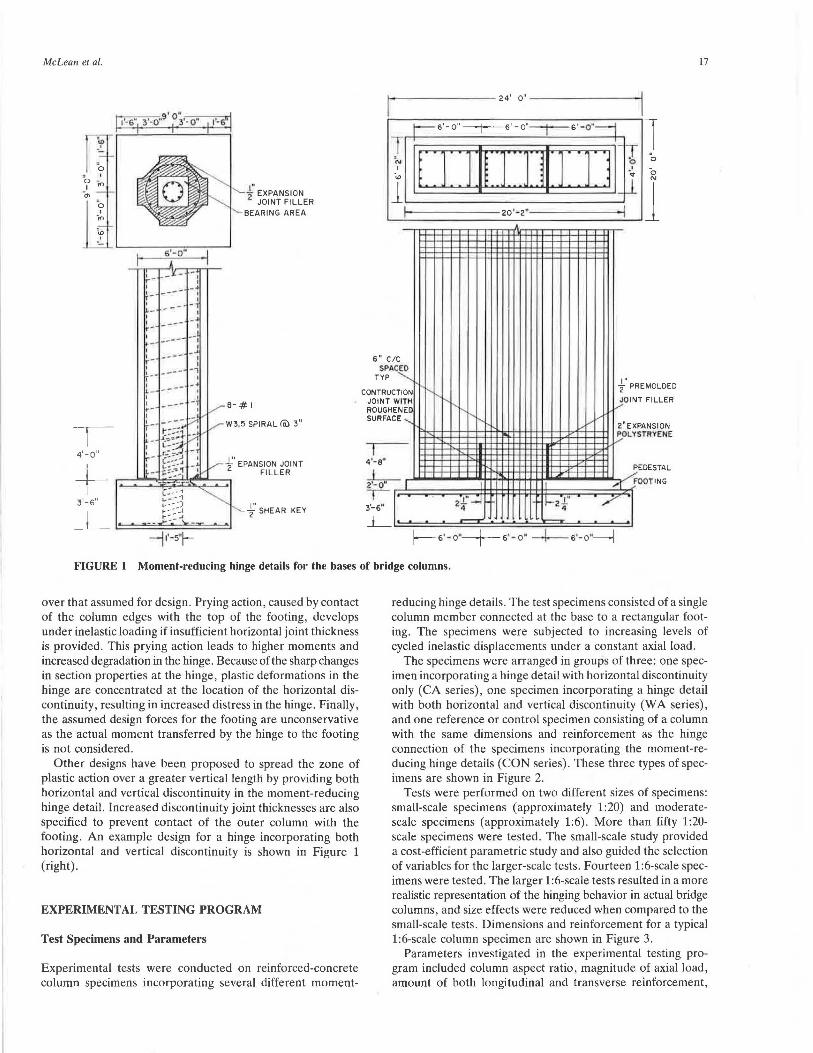
One approach to the design of the moment-reducing hinge details is to determine the size of the hinge required from the pure axial compressive capacity of the section, and to design for shear across the section by providing the amount of longitudinal steel required as determined from shear friction theory. A horizontal joint consisting of V4- to 1/2-in.-thick expansion joint material is provided at the throat region around the hinge perimeter to create partial discontinuity between the column and the footing. To further reduce the moment developed at the hinge section, the longitudinal bars are sometimes clustered at the center of the hinge, and the hinge is treated as a pin with no moment capacity. Both circular and rectangular arrangements of the reinforcement in the hinges have been used. Normally, only nominal transverse steel is provided. Occasionally, no transverse steel is used. An example design for a column incorporating a hinge of this type is shown in Figure 1 (left).
Several questions about the behavior of this hinge detail under seismic loading can be raised. The hinge is designed for the axial load capacity of the section, and research (2) has shown that reinforced-concrete columns tested under axial loads close to the maximum axial load allowed by American Concrete Institute (ACI) (3) exhibited significantly reduced ductility. Also, even though the hinge is assumed to be a pin connection, substantial moment actually develops at the hinge section even if the longitudinal bars are clustered. This process results in an increase in the shear and axial load in the column
McLean et al.
'o ' -,..,
'ID
I 4'-0"
+-3'-6"
' ' -~ I I
I I - ~ ~- .,..- .... - I
' _ ... -----.
' L-
-j1'-5"I-
"-.J.'.' EXPANSION 2
JOINT FILLER '-BEARING AREA
W3.5 SPIRAL (cl) 3"
,,.....- -f EPANSION JOINT FILLER
f' SHEAR KEY
T ;... ' "' l
I
'
CIC PACED p -.....,__
6" s
TY
UCTION CONTR JOIN ROUG SURF
T WITH HEN ED ACE ......_
4'-a" J__ 2'-0 .
I -,-3'-6"
.l_
24' o" I
f- 6'-o" ------j--6' -o"--t---6 ' -o"--j 1 l~::r :r1u:::n111 :i1
,! 0 ' .... I
0 _, 0 N
l 20•-2•
;-., r-..i'-
'r--;-.~
I;
,...
1
2.f' -4 1-zf -·
I
'
f' PRE MOLDED
FILLER JOINT v ,..,,..,
2"EXPA NSION TRYENE i,!:.OLYS
PE
...., FO
/
DESTAL
OTING
f--6 '-o"--+-s•-o• -1---- s·-o •~
17
FIGURE 1 Moment-reducing hinge details for the bases of bridge columns.
over that assumed for design . Prying action, caused by contact of the column edges with the top of the footing, develops under inelastic loading if insufficient horizontal joint thickness is provided. This prying action leads to higher moments and increased degradation in the hinge. Because of the sharp changes in section properties at the hinge, plastic deformations in the hinge are concentrated at the location of the horizontal discontinuity, resulting in increased distress in the hinge. Finally, the assumed design forces for the footing are unconservative as the actual moment transferred by the hinge to the footing is not considered.
Other designs have been proposed to spread the zone of plastic action over a greater vertical length by providing both horizontal and vertical discontinuity in the moment-reducing hinge detail. Increased discontinuity joint thicknesses are also specified to prevent contact of the outer column with the footing. An example design for a hinge incorporating both horizontal and vertical discontinuity is shown in Figure 1 (right).
EXPERIMENTAL TESTING PROGRAM
Test Specimens and Parameters
Experimental tests were conducted on reinforced-concrete column specimens incorporating several different moment-
reducing hinge details . The test specimens consisted of a single column member connected at the base to a rectangular footing. The specimens were subjected to increasing levels of cycled inelastic displacements under a constant axial load.
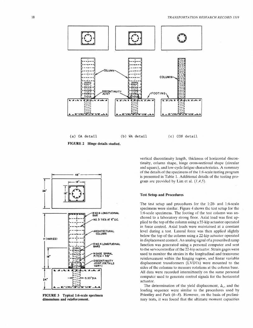
The specimens were arranged in groups of three: one specimen incorporating a hinge detail with horizontal discontinuity only (CA series), one specimen incorporating a hinge detail with both horizontal and vertical discontinuity (WA series), and one reference or control specimen consisting of a column with the same dimensions and reinforcement as the hinge connection of the specimens incorporating the moment-reducing hinge details (CON series). These three types of specimens are shown in Figure 2.
Tests were performed on two different sizes of specimens: small-scale specimens (approximately 1: 20) and moderatescale specimens (approximately 1:6). More than fifty 1:20-scale specimens were tested. The small-scale study provided a cost-efficient parametric study and also guided the selection of variables for the larger-scale tests. Fourteen 1:6-scale specimens were tested. The larger 1:6-scale tests resulted in a more realistic representation of the hinging behavior in actual bridge columns, and size effects were reduced when compared to the small-scale tests. Dimensions and reinforcement for a typical 1:6-scale column specimen are shown in Figure 3.
Parameters investigated in the experimental testing program included column aspect ratio, magnitude of axial load, amount of both longitudinal and transverse reinforcement,
18
(a) CA detail
FIGURE 2 Hinge details studied.
- ---- 48" -----
r r---- 111"--i T .
28" 18"!>0• l ..__._l_-_____,
I H (VARIES)
8 NQ 6 LONGITUDINAL BAR
NO. 3 TIES AT 6" O.C.
AROilTECTURAL COLUMN
8 N0. 4 LONGITUDINAL BARS
9GAGE SPIRAL PITCH• 718"
DISCONTINUITY JOINT I DETAILS VARY)
FIGURE 3 Typical 1:6-scale specimen dimensions and reinforcement.
TRANSPORTATION RESEARCH RECORD 1319
[QJ 0
(b ) WA de tail (c) CON detail
vertical discontinuity length, thickness of horizontal discontinuity, column shape, hinge cross-sectional shape (circular and square), and low-cycle fatigue characteristics. A summary of the details of the specimens of the 1 :6-scale testing program is presented in Table 1. Additional details of the testing program are provided by Lim et al. (1,4,5).
Test Setup and Procedures
The test setup and procedures for the 1 :20- and 1 :6-scale specimens were similar. Figure 4 shows the test setup for the 1:6-scale specimens. The footing of the test column was anchored to a laboratory strong floor. Axial load was first applied to the top of the column using a 55-kip actuator operated in force control. Axial loads were maintained at a constant level during a test. Lateral force was then applied slightly below the top of the column using a 22-kip actuator operated in displacement control. An analog signal of a prescribed ramp function was generated using a personal computer and sent to the servocontroller of the 22-kip actuator. Strain gages were used to monitor the strains in the longitudinal and transverse reinforcement within the hinging region, and linear variable displacement transformers (L VDTs) were mounted to the sides of the columns to measure rotations at the column base. All data were recorded intermittently on the same personal computer used to generate control signals for the horizontal actuator.
The determination of the yield displacement, ~Y' and the loading sequence were similar to the procedures used by Priestley and Park (6-8). However, on the basis of preliminary tests, it was found that the ultimate moment capacities
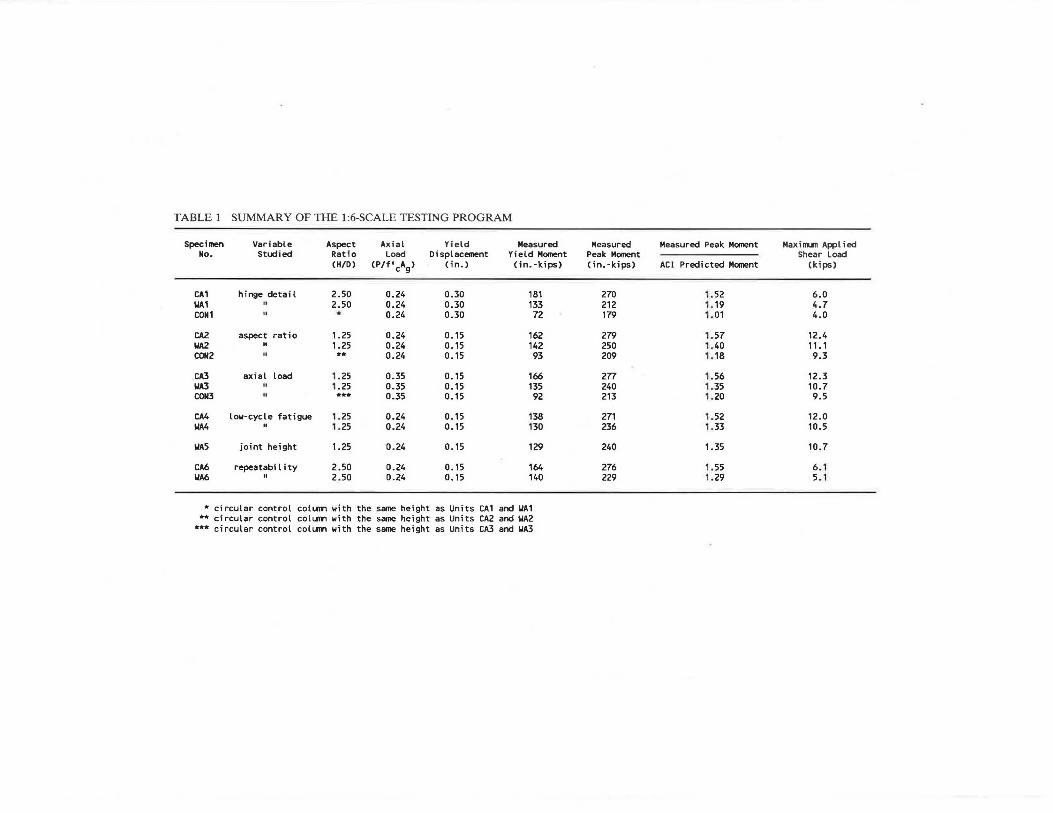
TABLE 1 SUMMARY OF THE 1:6-SCALE TESTING PROGRAM
Specimen Variable Aspect Axi a l Yield Measured Measured Measured Peak Moment Maxi nun Applied No. Studied Ratio Load Displacement Yield Moment Peak Moment Shear Load
CH/0) (P/f'cAg> C in.) Cin.-kips) Cin. - kips) ACI Predicted Moment (kips)
CA1 hinge detail 2.50 0.24 0.30 181 270 1. 52 6 .0 llA1 II 2.50 0.24 0.30 133 212 1. 19 4.7 CON1 II * 0.24 0.30 72 179 1.01 4 .0
CA2 aspect ratio 1.25 0.24 0.15 162 279 1.57 12.4 llA2 II 1.25 0.24 0.15 142 250 1.40 11.1 CON2 II ** 0.24 0.15 93 209 1. 18 9.3
CA3 axial load 1.25 0.35 0.15 166 277 1.56 12.3 llA3 II 1.25 0.35 0.15 135 240 1.35 10.7 CON3 " *** 0.35 0.15 92 213 1.20 9 . 5
CA4 low-cycle fatigue 1. 25 0.24 0.15 138 271 1. 52 12.0 llA4 II 1. 25 0.24 0.15 130 236 1.33 10.5
llA5 joint height 1.25 0.24 0. 15 129 240 1.35 10.7
CA6 repeatability 2. 50 0.24 0.15 164 276 1. 55 6 . 1 llA6 II 2.50 0.24 0.15 140 229 1. 29 5. 1
* c rcular control coll.llrl w th the same he ght as Un ts CA1 and llA1 ** c rcular control colU111'1 w th the same he ght as Un ts CA2 and llA2
*** c rcular control colunn w th the same he ght as Un ts CA3 and llA3

20
I ... ,_ ____ 10'
28"x 14"x 1·1/2" END PLATE ~1
STRONG FLOOR
FIGURE 4 Test setup for the 1:6-scale specimens.
and stiffnesses, and hence the yield displacements, varied in columns with different details. However, to better compare the hinging behavior of columns with different hinge details, parallel sets of columns were subjected to the same displacement history. The typical loading sequences used for the tests was two cycles at displacement ductility factors (i.e., multiple values of ily) ofµ = 1, 2, 4, 6, 8, 10 and 12 unless premature failure of the specimen caused a halt to the testing.
TEST RESULTS AND DISCUSSION
A summary uf lhe lesl resulls fur all 1 :6-srnle lesl spet:imens is presented in Table 1. Column performance was evaluated with respect to the moment capacity and displacement ductility attained, the overall hysteresis behavior, and degradation and energy dissipation characteristics. Rather than discuss the results of each specimen individually, results of groups of specimens are presented to facilitate correlation of the influence of various parameters with column performance and to obtain behavioral trends.
General Behavior
Hysteresis Behavior
Figure 5 shows typical load-displacement hysteresis curves for 1:6-scale columns incorporating details CA and WA and a comparable control column (Units CA2, WA2, and CON2). These columns were subjected to an axial load level of 0.24f~Ag. The aspect ratio for the columns incorporating the modified details was 1.25 measured with respect to the outer column, which corresponded to an aspect ratio of 3.75 for the control column. Longitudinal and volumetric reinforcing ratios in the hinges were 5.7 and 1.46 percent, respectively. The lateral loads presented in these plots are the true loads on
"'C c 0 _J
c L.. Cl> ..... c
TRANSPORTATION RESEARCH RECORD 1319
14 Unit CA2 12
10
-2
-· -· -· _J - 10
- 12
- 14
- 11 +-----..,--.....---..---1---.----.---.----1 -2 -1 0
Displacement (in.)
1• Unit WA2
UJ 10
a. ~
...........
"'C c 0 _J
c L.. Cl> ..... c
-2
-· -· -· _J -10
,.... UJ a. ~
........... "'C c 0
_J
c L.. Cl> ..... c
_J
-12
-·· -11-t---.---.---.....---1---..----.---.----1 -2 -1
Displacement (in.) 11-.--------------.------------, 14
12
10
-2
-· -· -· -10
-12
-14
Unit CON2
-11 -1------,---.---.---1--~~~~--~--1
-· -1
Displacement (in.)
FIGURE 5 Load-displacement hysteresis curves for Units CA2, W A2, and CON2.
the specimens, including P-ll effects and secondary effects from the axial load. The hysteresis curves for all three specimens are very stable even at displacement levels of µ = 12. No evidence of any sudden drop in load-carrying capability was observed, and the plastic hinges continued to absorb energy throughout the tests.
The theoretical ultimate lateral load, calculated from ACI methods and using measured material strengths with a material reduction factor of one, is also shown in each of these figures. Figure 5 indicates that substantial enhancement of the measured flexural strength above the ACI-predicted values was obtained for these columns. This strength enhancement is caused by increases in concrete strength and ductility
McLean et al.
because of the confinement provided by the spiral, and by the increased strength of the steel in the strain-hardening region. Results from the 1:6-scale tests indicated average enhancement values of 1.17, 1.35, and 1.52 for control columns, columns with detail WA, and columns with detail CA, respectively. The greater strength enhancement in the columns with the modified hinge details is caused by the additional confinement provided by the outer column surrounding the hinge detail. Figure 5 also indicates that hysteresis curves for the column incorporating detail CA are somewhat narrower than those for the column with detail WA and for the control column. This result indicates a reduced energy dissipation capacity in the hinge with the CA detail.
Shear Degradation
Figure 6 shows the plots of the shear strength envelope curves for Units CAl, WAl, and CONl. The shear strength envelope curve is obtained by plotting the maximum shear force attained at each peak displacement level with respect to that displacement. The columns with the moment-reducing details exhibited less strength degradation than did the control column, possibly because of the additional confinement provided around the hinge region by the outer column. Figure 6 also indicates that the column with detail CA exhibited the greatest stiffness and that the control column exhibited the least stiffness. Two reasons can be cited for the difference in stiffnesses observed in these specimens. First, the elastic stiffness of the control column is less than that of the outer columns with the moment-reducing details. Second, the moment-reducing details produce pinching of the rebars crossing the column-tofoundation connection, thereby inducing larger strain values in the rebars of the moment-reducing details .
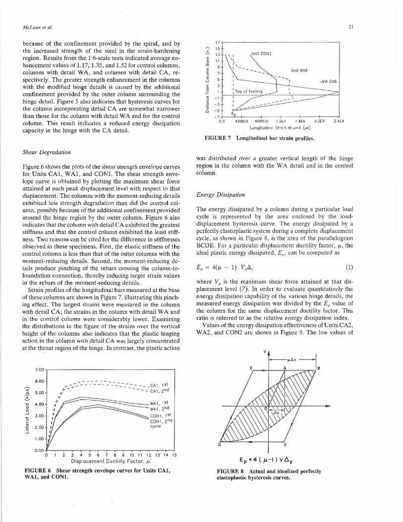
Strain profiles of the longitudinal bars measured at the base of these columns are shown in Figure 7, illustrating this pinching effect. The largest strains were measured in the column with detail CA; the strains in the column with detail WA and in the control column were considerably lower. Examining the distributions in the figure of the strains over the vertical height of the columns also indicates that the plastic hinging action in the column with detail CA was largely concentrated at the throat region of the hinge. In contrast, the plastic action
7 .00
6.00 ,...... "' 5.00 Q_
:.>: ~
1'.l 4.00 0 0 _J
3.00 ~ 2 2.00 0 _J
1.00
0.00 0
--:----_-_-_-_-_-_-_------ CA1 1st ,,:- - - - - - - - --- CA 1, 2nd
// ' II
,11 ~----..;;-~-WA1, 1st
I ' - WA1,2nd 1 CON1 1st
CON1:2nd cycle
2 3 4 5 6 7 8 9 10 11 12 13 14 15
Displacement Ductility Factor, µ
FIGURE 6 Shear strength envelope curves for Units CAI, WAI, and CONI.
21
17
i 15
13
" " 11 0 CD
9 c E 7 " 0 5 u E 3 ~
LL
"' - 1 u c
~ -3
Ci -5
4000.0 8000.0 1.2E4 1.6E4 2.0E4 2.4E4
Longitudinal Strain at µ=6 (µe)
FIGURE 7 Longitudinal bar strain profiles.
was distributed over a greater vertical length of the hinge region in the column with the WA detail and in the control column.
Energy Dissipation
The energy dissipated by a column during a particular load cycle is represented by the area enclosed by the loaddisplacement hysteresis curve. The energy dissipated by a perfectly elastoplastic system during a complete displacement cycle, as shown in Figure 8, is the area of the parallelogram BCDE. For a particular displacement ductility factor, µ , the ideal plastic energy dissipated, EP, can be computed as
(1)
where VP is the maximum shear force attained at that displacement level (7). In order to evaluate quantitatively the energy dissipation capability of the various hinge details, the measured energy dissipation was divided by the EP value of the column for the same displacement ductility factor. This ratio is referred to as the relative energy dissipation index.
Values of the energy dissipation effectiveness of Units CA2, WA2, and CON2 are shown in Figure 9. The low values of
v
Ep "4 ( µ.-1) V b.y
FIGURE 8 Actual and idealized perfectly elastoplastic hysteresis curves.

22
0 .60
0 .50
0. w 0.40 ......... w
O.JO
2 J 4 5 6 7 B 9 10 11 12
Displacement Ductility Factor, µ
FIGURE 9 Relative energy dissipation index curves for Units CA2, WA2, and CON2.
EIEP atµ = 2 and 4 for the control column, Unit CON2, are caused by the inexactness in defining the actual yield displacement in the different columns, with the result that response of the control column is still largely elastic at these displacement levels. The figure indicates that the control column exhibited the greatest energy dissipation effectiveness and column with detail CA exhibited the least effectiveness. The reduced effectiveness in the column with moment-reducing details may be caused by the confining of the plastic action at the base of the column, particularly with the CA detail.
Effect of Various Parameters on Column Performance
A~pect Rutia
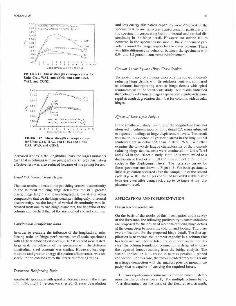
In order to evaluate the effects of column aspect ratio on the behavior of the hinge details, 1 :6-scale test results for modified rnlumns with asptl'.l ialios of 2.5 (Units WAl and CAl) and 1.25 (Units WA2 and CA2) and comparable control columns with aspect ratios of 7.5 (Unit CONl) and 3.75 (Unit CON2) are compared. The hysteresis curves for Units WA2, CA2, and CON2 and Units WAl, CAl, and CONl are shown in Figures 5 and 10 , respectively . The hysteresis curves for the two sets of specimens are similar , indicating that flexure dominated the behavior of the columns even with low aspect ratios .
The shear strength envelope curves for the two sets of specimens are shown in Figure 11. To account for the different lateral load levels associated with columns of different heights, the shear force, V, is plotted normalized with respect to the yield shear force , VY. The figure indicates that greater strength degradation occurred in the columns with the higher aspect ratio.
Level of Axial Load
In order to examine the effect of level of axial load on hinge performance, 1:6-scale Units WA2, CA2, and CON2 and Units WA3, CA3, and CON3 were tested with axial load levels of 0.24/; A g and 0.35/: A g, respectively . The shear strength envelope curves for these specimens are shown in Figure 12. From the figure, higher axial load resulted in greater
-c a 0
_J -I
a -2 ~
Cl> -J ...., a -• _J -· -·
,,...._, Ul a.
:i: ,__.. -c a 0 _J
a -2 ~
Cl> -J ...., a -· _J -· --·
- 7 -·
,,...._, : ~ (/) • .J a. I
:i: J ~ ,__.. 2 -
-c I a r ~
0 _J _, -a -2 J ~
cu -.l _; ...., a -· ~ _J -· ~
-· J _, i
TRANSPORTATION RESEARCH RECORD 1319
-2 Q
Displacement (in.)
Un it WA1
-2 0
Displacement (in.)
Unit CON1
-2 0
Displacement (in.)
FIGURE IO Load-displacement hysteresis curves for Units CAI, WAI , and CONl.
degradation in the control columns. However, axial load seemed to have little effect in the columns with the modified hinge details, particularly in the column with the CA detail. The reason that these columns are relatively unaffected by axial load level may be the confining effect provided around the hinge region by the outer column .
Horizontal Discontinuity Joint Thickness
When insufficient discontinuity joint thickness was provided in the moment-reducing hinge details, large prying forces developed from contact of the edges of the outer column with the top of the footing. This prying action resulted in greatly
McLean et al.
J .OO .,.-,W,,-,A-1 ,-:C,-A-1 , ..,.CO.,-N_l_: "'"'4 5:-" -co- lu-m-ns-, -,--fly-~-o -3"
2 80 WA2, CA2. CON2 : 22 5" columns, <'>y~o l 5"
2 60
~ .;~ 11 /_/------<!: 2
.00 - -. CON2
> 1.80~-~~~~~I 1 60 - ' CA2
1 40 .------ - ----·--- - --- Ul
1.20 ,' \..CAl
1.00 1 2 3 4 5 6 7 8 9 10 11 12 13 14 15
Displacement Ductilily Factor,µ
FIGURE 11 Shear strength envelope curves for Units CAI, WAI, and CONI and Units CA2, WA2, and CON2.
"' > '->
2.40
2 20
2.00
1 BO
1.60
1.40
1.20 WA2, CA2, CON2: axial loodz:Q,24f~ Ag
WA3, CAJ, CON3: axial lood=0.35(~ Ag
2 3 4 5 6 7 8 9 10 ll 12 13 14 15 Displacement Ducti lity Factor,µ,
FIGURE 12 Shear strength envelope curves for Units CA2, WA2, and CON2 and Units CAJ, W AJ, and CONJ.
increased strains in the longitudinal bars and larger moments than that in columns with no prying action. Energy dissipation effectiveness was also reduced because of the prying forces.
Detail WA Vertical Joint Height
The test results indicated that providing vertical discontinuity in the moment-reducing hinge detail resulted in a greater plastic hinge length and lower longitudinal bar strains when compared to that for the hinge detail providing only horizontal discontinuity. As the length of vertical discontinuity was increased from one to two hinge diameters, the behavior of the column approached that of the unmodified control columns.
Longitudinal Reinforcing Ratio
In order to evaluate the influence of the longitudinal reinforcing ratio on hinge performance, small-scale specimens with hinge reinforcing ratios of 4, 6, and 8 percent were tested. In general, the behavior of the specimens with the different longitudinal steel contents was similar. However, less degradation and greater energy dissipation effectiveness was observed in the columns with the larger reinforcing ratios.
Transverse Reinforcing Ratio
Small-scale specimens with spiral reinforcing ratios in the hinge of 0, 0.94, and' 3.2 percent were tested. Greater degradation
23
and less energy dissipation capability were observed in the specimens with no transverse reinforcement, particularly in the specimen incorporating both horizontal and vertical discontinuity in the hinge detail. However, no sudden failure occurred in the specimens because of the confinement provided around the hinge region by the outer column. There was little difference in behavior between the specimens with 0.94 and 3.2 percent transverse reinforcement.
Circular Versus Square Hinge Cross Section
The performance of columns incorporating square momentreducing hinge details with tie reinforcement was compared to columns incorporating circular hinge details with spiral reinforcement in the small-scale study. Test results indicated that columns with square hinges experienced significantly more rapid strength degradation than that for columns with circular hinges.
Effects of Low-Cycle Fatigue
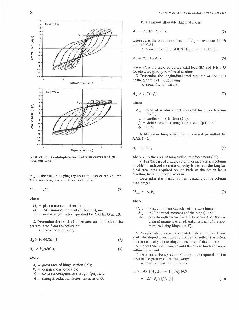
In the small-scale study, fracture of the longitudinal bars was observed in columns incorporating detail CA when subjected to repeated loadings at large displacement levels. This result was taken as evidence of greater distress in the longitudinal reinforcement in detail CA than in detail WA. To further examine the low-cycle fatigue characteristics of the momentreducing hinge details, tests were conducted on Units W A4 and CA4 in the 1 :6-scale study. Both units were cycled to a displacement level of µ = 10 and then subjected to multiple cycles at this displacement level. The hysteresis curves for these specimens are shown in Figure 13. For both specimens, little degradation occurred after the completion of the second cycle at µ = 10. The hinges continued to exhibit stable plastic behavior even after being cycled up to 16 times at that displacement level.
APPLICATIONS AND IMPLEMENTATION
Design Recommendations
On the basis of the results of this investigation and a survey of the literature, the following preliminary recommendations are proposed for the design of moment-reducing hinge details at the connection between the column and footing. There are two applications for the proposed hinge detail. The first application is to reduce the moment capacity in a column that has been oversized for architectural or other reasons. For this case, the column foundation connection is designed to carry the required forces resulting from the bridge analysis. The second application is to create as near as possible a pinned connection. For this case, the recommended procedures result in a hinge connection with the smallest possible moment capacity that is capable of carrying the required forces.
1. From equilibrium requirements for the column, determine the design shear force, V,,. For multiple column bents, Vu is determined on the basis of the flexural overstrength,
24
•• , .. Unit CA4 12
ID
,..... "' Q.
~ "O 0 0
...J
e -2
., -· . 0 -· ...J
-e -10
-12
-·· -·· -2 _, Displacement (in.)
•• ,. Unit WA4 12
10
,..... ., Q.
~ "O 0 0
...J
0 -2
.... -· 2 0 -· ...J -· .
-10
-12 _,.
-·· -2 -1 0
Displacement (in .)
FIGURE 13 Load-displacement hysteresis curves for Units CA4 and WA4.
MP, of the plastic hinging region at the top of the column. The overstrength moment is calculated as
(2)
where
MP = plastic moment of section, M" = ACI nominal moment (of section), and
<l>o = overstrength factor, specified by AASHTO as 1.3 .
2. Determine the required hinge area on the basis of the greatest area from the following:
a. Shear friction theory:
Ag ~ V)(0.2<j>f/)
Ag ~ V,,/(800<!>)
where
A8
= gross area of hinge section (in2);
v" = design shear force (lb); J: = concrete compressive strength (psi); and
<!> = strength reduction factor, taken as 0.85 .
(3)
(4)
TRANSPORTATION RESEARCH RECORD 1319
b. Maximum allowable diagonal shear:
A c = V,,![10 (f/) 112 <1>] (5)
where Ac is the core area of section (A8
cover area) (in2 )
and <Pis 0.85. c. Axial stress limit of 0.7// (to ensure ductility) :
A8 "" P,,1(0. ?<Pfc') (6)
where P,, is the factored design axial load (lb) and ct> is 0. 75 for circular, spirally reinforced sections.
3. Determine the longitudinal steel required on the basis of the greatest of the following:
a. Shear friction theory:
(7)
where
Avr = area of reinforcement required for shear fraction (in. 2);
µ = coefficient of friction (1.0) ; f,. = yield strength of longitudinal steel (psi); and <P = 0.85.
b. Minimum longitudinal reinforcement permitted by AASHTO:
A,= O.OlAg (8)
where A, is the area of longitudinal reinforcement (in2).
c. For the case of a single column or an oversized column in which a reduced moment capacity is desired, the longitudinal steel area required on the basis of the design loads resulting from the bridge analysis.
4. Determine the plastic moment capacity of the column base hinge:
where
Mpbh = plastic moment capacity of the base hinge, M,, = ACI nominal moment (of the hinge); and
(9)
cj>0 = overstrength factor ( = 1.6 to account for the increased moment strength enhancement of the moment-reducing hinge detail).
5. As applicable, revise the calculated shear force and axial load (developed from framing action) to reflect the actual moment capacity of the hinge at the base of the column.
6. Repeat Steps 2 through 5 until the design loads converge within 10 percent.
7. Determine the spiral reinforcing ratio required on the basis of the greater of the following:
a. Confinement requirements :
Ps ~ 0.45 [(A.IAc) - 1] le' 11;. [0.5
+ 1.25 P,,I( cj>f/ A 8 ) ] (10)
McLean et al.
and
(11)
where [0.5 + 1.25 P.J(<l>f;A8 )] is greater than or equal to 1.0 and <l> is 0.75.
b. Diagonal shear requirements (V" = <J>Vc + <J>Vs):
where
S = 4 A ,p/(psdc), A sp = cross-sectional area of spiral bar ,
de = outside diameter of spiral, s = spacing of spiral, and
<l> = 0.85.
8. Detailing of the moment-reducing hinge:
(12)
a. Provide a '12-in.-thick vertical discontinuity joint with a height equal to the hinge diameter.
b. Provide a length of 1.25 times the rebar development length for the longitudinal bars above the top of the vertical discontinuity joint for anchorage into the column, and ensure proper anchorage into the footing.
c. Provide a horizontal discontinuity joint thickness of at least 2 in. (in some cases, greater thicknesses may be needed to prevent the contact of the outer column edge with the footing).
d. Provide clear spacing of the spiral reinforcement not greater than 6 times the hinge longitudinal bar diameter and not more than 3 in.
e. Provide a 1/2-in. shear key at the column-foundation connection.
9. Base the design of the footing on the maximum axial load and actual plastic moment at the base of the column.
Design Example
This example illustrates the application of the proposed design recommendations. The column section and design forces used in the example were obtained from the example problem presented in Appendix A of the 1983 AASHTO Guide Specifications for Seismic Design of Highway Bridges (9).
The column has a clear height of 22 ft and an overall diameter of 4 ft. The factored design axial load and moment for this column are Pu = 1,141 kips and Mu = 3,804 kip-ft. The specified concrete compressive strength, Jc' , is 4,000 psi, and a yield strength of fv = 60,000 psi is specified for both the longitudinal and transverse reinforcements. The slenderness ratio for the column selected for the example is slightly greater than that for which slenderness effects may be neglected, and thus slenderness effects should be considered. However, for simplicity, slenderness is not considered in this example.
Using the appropriate strength reduction factors and the ACI column chart, the column requires 43 No. 10 bars for longitudinal reinforcement. This yields a longitudinal reinforcing ratio of p, = 0.03, which is within the limits specified by AASHTO (9).
25
The design for the moment-reducing hinge detail is presented in the step-by-step procedure of the recommendations outlined previously .
Step 1. The column shear force is obtained from the overstrength plastic moment capacity of the top of the column (initially, the column is considered pinned at the base):
= 1.3 x 5,406/22 = 319 kips (13)
where L., is the height of the column. The nominal moment capacity, Mn = 5,406 kip-ft , is obtained for the column using the ACI design chart for a longitudinal reinforcing ratio of 3 percent and a clear cover of 2 in., with the strength reduction factor taken as unity.
Step 2. The required circular hinge area is determined on the basis of the following:
a. Shear friction theory:
A 8 ~ V.J(0.2<j>f/)
= 319/(0.2 x 0.85 x 4) = 469 in. 2
Ag~ Vj800<j>
= 319 x 1,000/(0 .85 x 800) = 469 in .2
b. Maximum allowable diagonal shear:
Ac ~ V., [10(fc')l12<J>J
319 000 - . 2
0.85 x 10 x (4 000) 1n - 593 m.
(14)
(15)
(16)
On the basis of the required core area, a core diameter of 28 in . is required. With a 2-in. cover, the core and gross areas required are A c = 615 in .2 and Ag = 804 in .2, respectively .
c. Axial stress limit of 0. 7fc':
A8 ~ Pj(0.7fc'<l>)
= 1,141/(0.75 x 0.7 x 4) = 543 in. 2 (17)
Therefore, a gross hinge area of A8
= 804 in.2 should be provided.
Step 3. On the basis of shear friction theory, the longitudinal steel required is
A ,,r ~ V,,I( <j>µ.f,.)
= 319/(0.85 x 1 x 60) = 6.25 in. 2 (18)
Because this value is less than 1 percent of the gross hinge area , a total of 8 No. 9 bars will be used to provide a longitudinal reinforcement ratio of 1 percent .
Step 4. The plastic moment capacity of the base hinge is
Mpbh = <l>oMnbli = 1.6 X 991 = 1,586 kip-ft (19)
Step 5. Using the preliminary design of the base hinge, the column shear force is revised to reflect the actual moment capacity at the base of the column. The revised column shear

26
force V~ resulting from the plastic moments developed at both the top and bottom of the column is given by
(1.3 x 5,406 + 1.6 x 991)/22 = 392 kips (20)
where Mp,h and Mpbh are the plastic moments at the top and bottom of the column, respectively.
Step 6. Because of the plastic moment at the base hinge, the column shear force is increased by 23 percent. The design of the base hinge is revised by repeating Steps 2 through 5 until the shear force converges within 10 percent. A final base hinge with a gross diameter of 35 in. and 10 No. 9 longitudinal bars is obtained. The plastic moment capacity of the hinge, <f>oMnbh• is 2,035 kip-ft.
Step 7. The transverse reinforcement required hased on confinement is the greater of
p,~0.45[(A8 /Ac) - l]fc'lf, [0.5 + l.25P)(<f>f/Ag)]
(962 ) 4 ( 1,141 )
= 0.45 755 - 1 60 °·5 + 1.25 x 0.75 x 4 x 962
= 0.0082 (21)
and
p,~0.12 (fc'lfy)[0.5 + l.25P,,l(<!>fc'Ag)]
= 0.12 x (4/60) (o.5 + 1.25 x 0
1'141
96 )
.75 x 4 x 2
= 0.008 (22)
148'1
-- 35• -
i,..--10-#9
I I/
V # 5 SPIRAL ta)
I/ 2f CIC 1.25 ld IN , TENSION •1.25•38' •48°
HE +--2''-
I' IGHT OF VERTICAL 2 DISCONTINUITY
JOINT • BASE HINGE DIA • 35"
z" I ~ ""
_l_ TOP OF FOOTING
f SHEAR KEY I
FIGURE 14 Cross-section of the moment-reducing hinge detail for the design example.
TRANSPORTATION RESEARCH RECORD 1319
The volumetric ratio required based on shear considerations is
p, ~ 2/fy [(V)<f>Ac) - 2 (fc') 112J
= 2 x ( 412 - 2 x (4,000)'12)
60 0.85 x 755 1,000
= 0.017 (23)
Therefore, a transverse reinforcement ratio of 1.7 percent is provided using No. 5 spiral at a pitch of 2.5 in.
Step 8. A cross-sectional view showing the details of the moment-reducing hinge is shown in Figure 14.
For the column selected for the example, the plastic moment capacities of the column and the hinge, including the overstrength factors, are 7 ,028 and 2,035 kip-ft, respectively. Thus, a 70 percent reduction of moment transferred to the foundation is obtained by incorporating the moment-reducing hinge detail when compared to a foundation connection consisting of the constant cross section and reinforcement provided in the column.
CONCLUSIONS AND RECOMMENDATIONS
Conclusions
On the basis of the results of this investigation, the following conclusions are made:
1. Columns with the moment-reducing hinge details of this study exhibited stable hinging behavior similar to that of a conventional column with the same dimensions and reinforcement as that of the hinge.
2. Substantial enhancement of the measured flexural strength over that predicted by current design approaches was observed for all columns. Average enhancement values of 1.17, 1.35, and 1.52 were obtained for conventional columns, columns incorporating moment-reducing hinge details providing both horizontal and vertical discontinuity, and columns incorporating moment-reducing hinge details providing only horizontal discontinuity, respectively.
3. Greater distress in the longitudinal bars and reduced energy dissipation effectiveness was observed in the hinge detail with only horizontal discontinuity when compared to the other hinge details of this study.
4. Flexure controlled the behavior of all of the columns, including those with an aspect ratio of 1.25. However, greater strength degradation occurred in the columns with higher aspect ratios.
5. Higher axial load levels had only a minor effect on the performance of columns with the moment-reducing hinge details. This lack of effect was attributed to the confinement around the hinge provided by the outer column.
6. Columns tested with small horizontal discontinuity joint thicknesses experienced prying action because of contact of the column edges with the footing. This prying action resulted in increases in the hinge moments and reinforcement strains.
7. The concrete of the outer column provided significant lateral confinement around the hinge region in the columns
McLean et al.
with the moment-reducing hinge details. However, adequate confining reinforcement was still required in order to obtain stable plastic hinging behavior and satisfactory energy dissipation in the column.
8. Columns with circular spirally reinforced hinge details exhibited better performance than did columns with square hinge details with tie reinforcement.
Recommendations
The following preliminary recommendations are made on the basis of the results of this study and a survey of the literature.
1. Both vertical and horizontal discontinuity should be provided in the moment-reducing hinge detail. The thickness of the discontinuity joint should be selected to accommodate the anticipated rotation requirements of the column base.
2. The column and the moment-reducing hinge detail should be designed on the basis of the actual moment capacity of the hinge detail. Rational procedures based on known principles of performance should be used in the design.
3. Circular hinge sections should be used in the momentreducing hinge, and spiral reinforcement should be provided over the full length of the hinge detail.
4. The hinge section at the base of the column should be designed for a value lower than the maximum allowable axial load capacity to ensure ductility when subjected to seismic loadings.
5. Conservative evaluations were used for several parameters not investigated in this study, including anchorage requirements of the reinforcing bars, very high axial load levels, shear strength, and the effect of clustering the longitudinal bars. Further research is needed to precisely define the influence of these parameters on the behavior of the momentreducing hinge details. The current information should also be supplemented by testing multiple column bents incorporating moment-reducing hinge details at the bases of the columns.
27
ACKNOWLEDGMENTS
The research presented in this paper was funded by the Washington State Transportation Center (TRAC). The authors acknowledge the valuable assistance of Umesh Vasishth of Exeltech Engineering.
REFERENCES
1. K. Y. Lim, D. I. McLean, and E. H. Henley. Moment-Reducing Hinge Details for the Bases of Bridge Columns. In Transportation Research Record 1275, TRB, National Research Council, Washington, D.C., 1990, pp. 1-11.
2. K. Sakai and S. A. Sheikh. What Do We Know about Confinement in Reinforcement Concrete Columns? (A Critical Review of Previous Work and Code Provisions). ACI Structural Journal, Vol. 86, No. 2, American Concrete Institute, Detroit, Mich., MarchApril 1989, pp. 192-207.
3. ACI Committee 318. Building Code Requirements for Reinforced Concrete. ACI 318-83. American Concrete Institute, Detroit, Mich., 1983.
4. D. I. McLean, K. Y. Lim, and E. H . Henley. Moment-Reducing Hinge Details for the Bases of Bridge Columns. Washington State Department of Transportation, Olympia, July 1990.
5. K. Y. Lim and D. I. McLean. Scale Model Studies of MomentReducing Hinge Details in Bridge Columns. AC! Structural Journal, Vol. 88, No . 4, American Concrete Institute, Detroit, Mich., July-Aug. 1991, pp . 465-474.
6. M. J. N . Priestley and R . Park. Strength and Ductility of Bridge Substruc1ures. RRU Bulletin 71. National Roads Board, Wellington, New Zealand, 1984, 120 pp.
7. B. G. Ang, M. J. N. Priestley, and T. Paulay. Seismic Shear Strength of Circular Bridge Piers. Research Report 85-5. Department of Civil Engineering, University of Canterbury , New Zealand, 1985.
8. M. J . N. Priestley and R . Park. Strength and Ductility of Concrete Bridge Columns Under Seismic Loading. ACI Structural Journal, Vol. 84, No. 1, American Concrete Institute, Detroit, Mich., Jan.Feb. 1987, pp. 61-76.
9. Guide Specifications for Seismic Design of Highway Bridges. AASHTO, Washington, D.C., 1983.
Publication of this paper sponsored by Commiltee on General Structures.