behavior of reinforced concrete beam with opening€¦ · beam with opening dr. latha m s ... the...
TRANSCRIPT

http://www.iaeme.com/IJCIET/index.asp 581 [email protected]
International Journal of Civil Engineering and Technology (IJCIET) Volume 8, Issue 7, July 2017, pp. 581–593, Article ID: IJCIET_08_07_062
Available online at http:// http://www.iaeme.com/ijciet/issues.asp?JType=IJCIET&VType=8&IType=7
ISSN Print: 0976-6308 and ISSN Online: 0976-6316
© IAEME Publication Scopus Indexed
BEHAVIOR OF REINFORCED CONCRETE
BEAM WITH OPENING
Dr. Latha M S
Associate Professor, Department of Civil Engineering,
Sri Venkateshwara College of Engineering, Bangalore, India
Naveen Kumar B M
Assistant Professor, Department of Civil Engineering,
Sri Venkateshwara College of Engineering, Bangalore, India
ABSTRACT
ANSYS 10.0, a finite element software, has been used to simulate simply supported
RC beams consisting of circular openings with varying diameters in 3-D nonlinear finite
element method. The RC beam model is created using SOLID65, SOLID45 and LINK8
elements representing both linear and non-linear behavior of concrete, steel plate and
reinforcing bar respectively. The inherent assumption is that there is full displacement
compatibility between the reinforcement and the concrete and no bond slippage occurs.
The FE beam model is verified against experimental test data of RC solid beam without
opening available in literature and then a number of verified models of simply supported
RC beams with circular opening are loaded monotonically with two incremental
concentrated loads. A model with equivalent square opening of 133 mm in width is also
analyzed. An attempt is made to know the effects of circular opening size on the behavior
of RC beams from load-deflection curve, crack pattern and stress distribution. RC
rectangular beams with circular openings of diameter less than 44% of the depth of
beam (D) has no effect on the ultimate load capacity but circular openings with diameter
more than 44% of D reduces the ultimate load capacity at least 34.29%.
Key word: ANSYS, Beam Opening, Crack Pattern, Finite Element Method, Load Vs.
Deflection Curve, Modeling, Reinforced Concrete (RC) Beam, Stress Distribution.
Highlights: Study of reinforced concrete beam with circular opening with varying
percentage opening and its effect on load deflection curve, crack pattern and stress
distribution.
Cite this Article: Dr. Latha M S and Naveen Kumar B M, Behavior of Reinforced
Concrete Beam with Opening, International Journal of Civil Engineering and
Technology, 8(7), 2017, pp. 581–593.
http://www.iaeme.com/IJCIET/issues.asp?JType=IJCIET&VType=8&IType=7

Behavior of Reinforced Concrete Beam with Opening
http://www.iaeme.com/IJCIET/index.asp 582 [email protected]
1. INTRODUCTION
Beam openings may be of different shapes, sizes and are generally located close to the supports
where shear is dominant. In practical life it is quite often use to provide convenient passage of
environmental services which reduce the story heights of buildings and weight of concrete
beams as it improves the demand on the supporting frame both under gravity loading and
seismic excitation which results in major cost saving. Openings should be positioned on the
concrete beams to provide chords with sufficient concrete area for developing ultimate
compression block in flexure and adequate depth for providing effective shear reinforcement
[1].
Hanson (1969) tested a typical joist floor i.e. a series of longitudinally RC T-beams
representing square and circular openings in the web and found that an opening located adjacent
to the centre stub (support) produced no reduction in strength [2]. The test data reported by
Somes and Corley (1974) indicated that when a small opening (0.25 times the depth of the
beam) is introduced in the web of a beam which is unreinforced in shear, the mode of failure
remains essentially the same as that of a solid beam [3]. Salam (1977) investigated perforated
beams of rectangular cross section under two symmetrical point loads [4]. Siao and Yap (1990)
stated that the beams fail prematurely by sudden formation of a diagonal crack in the
compression chord when no additional reinforcement is provided in the members near the
opening (chord members) [5]. Mansur et al. (1991) tested eight RC continuous beams, each
containing a large transverse opening and found an increase in depth of opening led to a
reduction in collapse load. Mansur (1998) discussed about the effects of transverse opening on
the behavior and strength of RC beams under predominant shear and stated that opening
represents a source of weakness and the failure plane always passes through the opening, except
when the opening is very close to the support so as to bypass the potential inclined failure plane.
Abdalla et al. (2003) used fibre reinforced polymer (FRP) sheets to strengthen the opening
region in his experiment [6].
2. MODELING AND ANALYSIS PROCESS BY ANSYS
2.1. General Information
2.1.1. Dimension (Fig. 1)
Reinforced concrete beam: 100 x 2050 x 250
Steel plates at loading point: 100 x 100 x 10
Steel plates at Support: 100 x 50 x 10
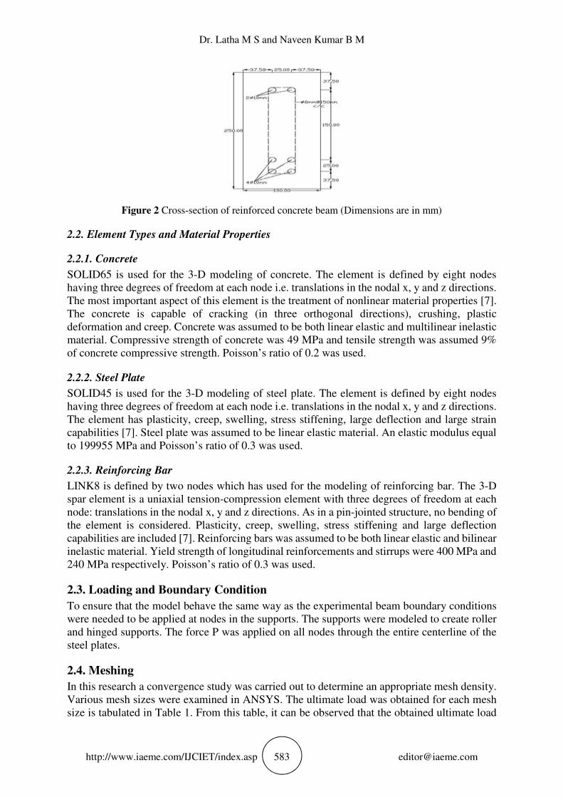
2.1.2. Steel reinforcement (Fig. 2) Top rebar: 4ø10mm
Bottom rebar: 2ø10mm
Stirrup: 2 legged ø8 mm @ 150 mm c/c
Figure 1 Reinforced concrete beam (Dimensions are in mm)
Dr. Latha M S and Naveen Kumar B M
http://www.iaeme.com/IJCIET/index.asp 583 [email protected]
Figure 2 Cross-section of reinforced concrete beam (Dimensions are in mm)
2.2. Element Types and Material Properties
2.2.1. Concrete
SOLID65 is used for the 3-D modeling of concrete. The element is defined by eight nodes
having three degrees of freedom at each node i.e. translations in the nodal x, y and z directions.
The most important aspect of this element is the treatment of nonlinear material properties [7].
The concrete is capable of cracking (in three orthogonal directions), crushing, plastic
deformation and creep. Concrete was assumed to be both linear elastic and multilinear inelastic
material. Compressive strength of concrete was 49 MPa and tensile strength was assumed 9%
of concrete compressive strength. Poisson’s ratio of 0.2 was used.
2.2.2. Steel Plate
SOLID45 is used for the 3-D modeling of steel plate. The element is defined by eight nodes
having three degrees of freedom at each node i.e. translations in the nodal x, y and z directions.
The element has plasticity, creep, swelling, stress stiffening, large deflection and large strain
capabilities [7]. Steel plate was assumed to be linear elastic material. An elastic modulus equal
to 199955 MPa and Poisson’s ratio of 0.3 was used.
2.2.3. Reinforcing Bar
LINK8 is defined by two nodes which has used for the modeling of reinforcing bar. The 3-D
spar element is a uniaxial tension-compression element with three degrees of freedom at each
node: translations in the nodal x, y and z directions. As in a pin-jointed structure, no bending of
the element is considered. Plasticity, creep, swelling, stress stiffening and large deflection
capabilities are included [7]. Reinforcing bars was assumed to be both linear elastic and bilinear
inelastic material. Yield strength of longitudinal reinforcements and stirrups were 400 MPa and
240 MPa respectively. Poisson’s ratio of 0.3 was used.
2.3. Loading and Boundary Condition
To ensure that the model behave the same way as the experimental beam boundary conditions
were needed to be applied at nodes in the supports. The supports were modeled to create roller
and hinged supports. The force P was applied on all nodes through the entire centerline of the
steel plates.
2.4. Meshing
In this research a convergence study was carried out to determine an appropriate mesh density.
Various mesh sizes were examined in ANSYS. The ultimate load was obtained for each mesh
size is tabulated in Table 1. From this table, it can be observed that the obtained ultimate load

Behavior of Reinforced Concrete Beam with Opening
http://www.iaeme.com/IJCIET/index.asp 584 [email protected]
for mesh size 40mm (77021 N) is nearest to the ultimate load of experimental beam (83000 N)
[6]. For this reason, the mesh size equal to 40 mm was chosen for this study. Fig. 3.a shows the
load-deflection relationship for different mesh sizes.
(a) (b)
Figure 3 Load vs. deflection curves for (a) different mesh sizes and (b) FE models and experimental
beam
Table 1 Different mesh sizes and corresponding ultimate loads
Mesh size (mm) Mesh 40 Mesh 70 Mesh 100
Ultimate load (N) 77021 76286 75368
2.5. Verification Study
A concrete beam of the dimensions and properties as same as the FE model of Abdalla et al.
(2003) was modeled in this FEA calibration study. As it is quite difficult to construct models
with stirrup and also it is much more time consuming, two FE models one with stirrup (Fig.
4.a) and another one without stirrup (Fig. 4.b), were compared to the beam of Abdalla (2003)
to ensure that the elements, material properties and convergence criteria are adequate to model
the response of the member and the correctness of simulation process.
(a) (b)
Figure 4 FE model (a) with stirrup and (b) without stirrup
The ultimate load of the RC solid beam obtained from the experimental test was 83000 N,
while the ultimate load extracted from ANSYS analysis outputs is 77021 N and 79603 N for
the model without stirrup and the model with stirrup respectively. Since the difference of
ultimate load between the model with and without stirrup is 3.24% therefore we used the FE
model without stirrup for further analysis purpose to save time and put more emphasis on the
analysis. The difference of ultimate load between the FE model and experimental beam is about
Dr. Latha M S and Naveen Kumar B M
http://www.iaeme.com/IJCIET/index.asp 585 [email protected]
7 % and it is proven that ANSYS software is an appropriate method to predict the behavior of
RC beams accurately. Fig. 3.b shows the load-deflection relationships for this verification
study.
3. CASE STUDY AND DISCUSSION
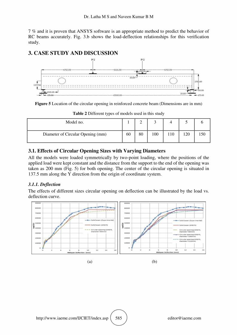
Figure 5 Location of the circular opening in reinforced concrete beam (Dimensions are in mm)
Table 2 Different types of models used in this study
Model no. 1 2 3 4 5 6
Diameter of Circular Opening (mm) 60 80 100 110 120 150
3.1. Effects of Circular Opening Sizes with Varying Diameters
All the models were loaded symmetrically by two-point loading, where the positions of the
applied load were kept constant and the distance from the support to the end of the opening was
taken as 200 mm (Fig. 5) for both opening. The center of the circular opening is situated in
137.5 mm along the Y direction from the origin of coordinate system.
3.1.1. Deflection
The effects of different sizes circular opening on deflection can be illustrated by the load vs.
deflection curve.
(a) (b)

Behavior of Reinforced Concrete Beam with Opening
http://www.iaeme.com/IJCIET/index.asp 586 [email protected]
(c) (d)
Figure 6 Load-deflection curves for (a) Model 1 & Solid beam, (b) Solid beam & Model 2, 3 & 4, (c)
Solid beam & Model 5 and (d) Solid beam & Model 6
3.1.1.1. Model 1
The diameter of the circular opening in this beam was 60 mm. According to Fig. 6.a, there is a
slight difference between the load-deflection curve of solid beam (from ANSYS) and model 1.
The curve for model 1 approximately coincides to the solid beam curve. Therefore, introducing
the circular opening with diameter equal to 24% of the depth of the beam has no effect on the
behavior of the beam. As the circular opening with 60 mm in diameter does not reduce the
concrete area necessary for the development of the compressive stress block at ultimate result,
the ultimate strength of the beam will not be affected by the presence of this circular opening.
3.1.1.2. Models 2, 3, and 4
The diameter for circular openings in models 2, 3, and 4 were 80, 100, and 110 mm respectively.
The predicted values of ultimate load capacity for models 2, 3 and 4 from ANSYS analysis
were 75857 N, 75759 N and 75624 N respectively (Fig. 6.b). The corresponding value for the
solid beam obtained from ANSYS was 77021 N and from experimental test was 83000 N. There
is around 2% reduction in the ultimate load capacity between models and solid beam which is
negligible. As the depth of the compression chord is greater than the depth of compressive stress
block for the circular opening with diameter less than 44% of the depth of the beam, so small
effect on the behavior of the beam arise.
3.1.1.3. Model 5 and 6
The diameter for circular openings of model 5 and 6 were 120 and 150 mm respectively. The
obtained value of the ultimate load capacity from ANSYS output for model 5 (Fig. 6.c) and 6
(Fig. 6.d) were 50611 N and 46750 N respectively, while the corresponding value for solid
beam was 77021 N. 34.29% capacity of the ultimate load reduces in model 5 and for model 6
it reduces upto 39.30%. In other words, by creating the circular opening with diameter equal to
48% and 60% of the depth of the beam, capacity of the ultimate load reduces to 34.29% and
39.30% respectively. It occurs due to cut of material from the compression zone and thereby
reduces the concrete area required for the development of the full compressive stress block at
ultimate load.
3.1.2. Crack Pattern
3.1.2.1. Crack Pattern at Ultimate Load for Simulated Models
For model 1 the main crack appears at the midspan and the failure is caused by flexural cracks
at the ultimate load which is quite similar to the solid beam without opening. From Fig. 7.a it

Dr. Latha M S and Naveen Kumar B M
http://www.iaeme.com/IJCIET/index.asp 587 [email protected]
can also be derived that the behavior of the beams with circular opening with diameter less than
24% of the depth of the beam is same as the solid beams without opening. The crack pattern for
the ultimate load is also same for model 2 (Fig. 7.b), 3 (Fig. 7.c) and 4 (Fig. 7.d) i.e. the main
cracks in these beams appear at the midspan and the failure caused by flexural crack. For both
model 5 (Fig. 7.e) and 6 (Fig. 7.f) the main cracks occur at the bottom and top chord; in addition,
the crack path led to the failure in the opening extends with an angle of 45 degrees from loading
points toward supports. From the crack propagation it can be observed that the failure mode is
shear at the opening region.
(a) (b)
(c) (d)
(e) (f)
Figure 7 Crack pattern at ultimate load of (a) Model 1, (b) Model 2, (c) Model 3, (d) Model 4, (e)
Model 5 and (f) Model 6
3.1.2.2. Comparison of Crack Propagation between Model 1 and Model 6
The first crack appears at supports for both model 1 and model 6 at 16200 N load (Fig. 8). At
load 20000 N flexural cracks are visible in both models. In model 6 not only flexural but also

Behavior of Reinforced Concrete Beam with Opening
http://www.iaeme.com/IJCIET/index.asp 588 [email protected]
diagonal tensile cracks appear around the opening region (Fig. 9). Flexural cracks propagate
from midspan towards support at load 26000 N in both models and cracks increase around the
opening region in model 6 (Fig. 10). At load 36000 N propagation of cracks continue in the
same way as before. Diagonal tensile crack in model 1, multiple cracks in model 6 and
compressive crack in both models also appear (Fig. 11). 46750 N is the ultimate load for model
6. In this stage cracks are well spread around the opening region and towards the support of
model 6 and failure mode is shear at the opening region. Multiple cracks occur in model 1 at
this load (Fig. 12).
(a) (b)
Figure 8 Crack at load 16200 N of (a) Model 1and (b) Model 6
(a) (b)
Figure 9 Crack at load 20000 N of (a) Model 1 and (b) Model 6
(a) (b)
Figure 10 Crack at load 26000 N of (a) Model 1 and (b) Model 6
Dr. Latha M S and Naveen Kumar B M
http://www.iaeme.com/IJCIET/index.asp 589 [email protected]
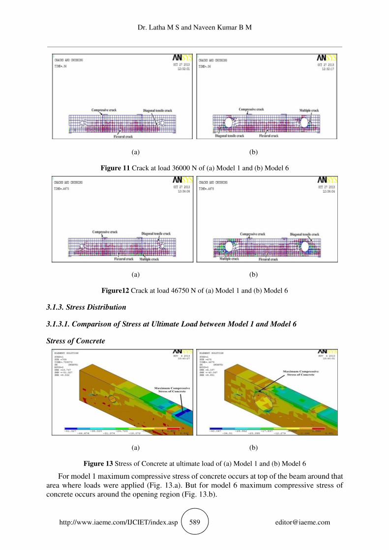
(a) (b)
Figure 11 Crack at load 36000 N of (a) Model 1 and (b) Model 6
(a) (b)
Figure12 Crack at load 46750 N of (a) Model 1 and (b) Model 6
3.1.3. Stress Distribution
3.1.3.1. Comparison of Stress at Ultimate Load between Model 1 and Model 6
Stress of Concrete
(a) (b)
Figure 13 Stress of Concrete at ultimate load of (a) Model 1 and (b) Model 6
For model 1 maximum compressive stress of concrete occurs at top of the beam around that
area where loads were applied (Fig. 13.a). But for model 6 maximum compressive stress of
concrete occurs around the opening region (Fig. 13.b).

Behavior of Reinforced Concrete Beam with Opening
http://www.iaeme.com/IJCIET/index.asp 590 [email protected]
Stress of Steel
(a) (b)
Figure 14 Stress of longitudinal reinforcement at ultimate load of (a) Model 1 and (b) Model 6
For model 1 maximum tensile stress of longitudinal reinforcement occurs at bottom rebar
of the beam near the midspan and it is 400 Mpa which is equal to the yield strength of the
longitudinal reinforcement (Fig. 14.a). For model 6 maximum tensile stress of longitudinal
reinforcement also occurs at bottom rebar of the beam near the midspan but it is 318.232 MPa
which is less than the yield strength of the longitudinal reinforcement 400 MPa (Fig. 14.b).
Table 3 Characteristics of the analyzed beams and summary of the results
3.2. Effect of Circular Opening Compared to the Equivalent Square Opening
In this section the RC beam with square opening (width = 133 mm) has been compared to its
equivalent circular opening of diameter 150 mm i.e. model 6.
All conditions and the situations of the openings were the same as all previous models. The
ultimate load capacity for square opening from ANSYS analysis was 42270 N (Fig. 15), while
the corresponding value for the solid beam (without opening) and model 6 obtained from
ANSYS were 77201 N and 46750 N respectively. The difference in the ultimate load capacity
between solid beam and circular opening is about 45% and for model 6 and equivalent square
opening (w = 133 mm) it is about 9.58%. It shows that square opening reduces the ultimate load
Dr. Latha M S and Naveen Kumar B M
http://www.iaeme.com/IJCIET/index.asp 591 [email protected]
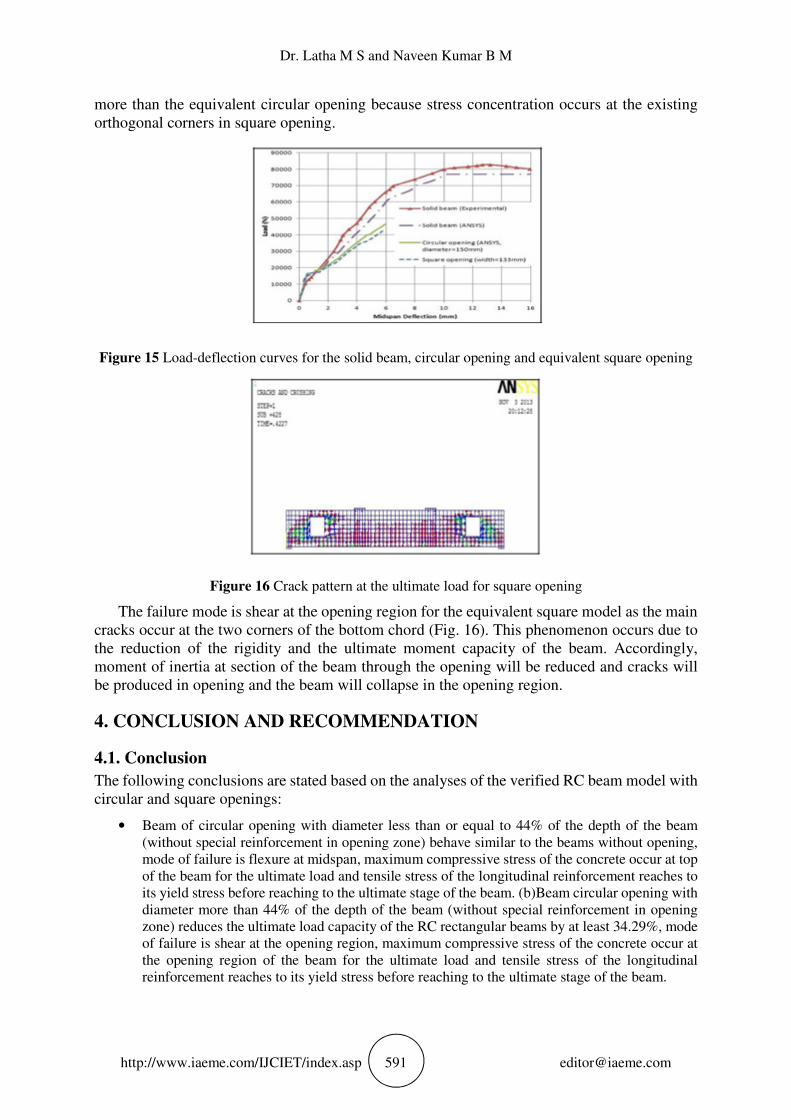
more than the equivalent circular opening because stress concentration occurs at the existing
orthogonal corners in square opening.
Figure 15 Load-deflection curves for the solid beam, circular opening and equivalent square opening
Figure 16 Crack pattern at the ultimate load for square opening
The failure mode is shear at the opening region for the equivalent square model as the main
cracks occur at the two corners of the bottom chord (Fig. 16). This phenomenon occurs due to
the reduction of the rigidity and the ultimate moment capacity of the beam. Accordingly,
moment of inertia at section of the beam through the opening will be reduced and cracks will
be produced in opening and the beam will collapse in the opening region.
4. CONCLUSION AND RECOMMENDATION
4.1. Conclusion
The following conclusions are stated based on the analyses of the verified RC beam model with
circular and square openings:
• Beam of circular opening with diameter less than or equal to 44% of the depth of the beam
(without special reinforcement in opening zone) behave similar to the beams without opening,
mode of failure is flexure at midspan, maximum compressive stress of the concrete occur at top
of the beam for the ultimate load and tensile stress of the longitudinal reinforcement reaches to
its yield stress before reaching to the ultimate stage of the beam. (b)Beam circular opening with
diameter more than 44% of the depth of the beam (without special reinforcement in opening
zone) reduces the ultimate load capacity of the RC rectangular beams by at least 34.29%, mode
of failure is shear at the opening region, maximum compressive stress of the concrete occur at
the opening region of the beam for the ultimate load and tensile stress of the longitudinal
reinforcement reaches to its yield stress before reaching to the ultimate stage of the beam.

Behavior of Reinforced Concrete Beam with Opening
http://www.iaeme.com/IJCIET/index.asp 592 [email protected]
• The circular opening has more strength than equivalent square opening with difference of 9.58%
in ultimate load capacity.
Figure 17 Load-deflection curves for the solid beam and all beams having different openings
discussed in this study
Figure 18 Strengthening with composite sheet in the opening region of RC beam
4.2. Recommendation
The following recommendations are suggested for future researches which were not covered in
the present study
• Stirrup can be used in model to get more accurate result.
• Based on the finite element method, future studies can include different types of loading to test further the design method. This comprises studies with continuous beams, multiple loading points, cyclic loading and different opening shapes and also includes examining the vertical location of the transverse openings in the RC beams.
• Strength of the RC beams can be increased by adding composite sheets (Fig. 18), by providing
high strength concrete or by additional steel reinforcement around the opening region.
REFERENCES
[1] Amiri, S., R. Masoudnia, Investigation of the Opening Effects on the Behavior of Concrete
Beams Without Additional Reinforcement in Opening Region Using Fem Method,
Australian Journal of Basic and Applied Sciences, 5(5),2011, 617-624.
[2] Hanson, J.M., Square openings in webs of continuous Joists, Portland Cement Association,
1969, pp: l-14.
[3] Somes, N.F. and W.G. Corley, Circular openings in webs of continuous beams, American
Concrete Institute, Detroit, MI, 1974, pp: 359-398.
Dr. Latha M S and Naveen Kumar B M
http://www.iaeme.com/IJCIET/index.asp 593 [email protected]
[4] Salam, S.A., Beams with openings under different stress conditions, Conference on Our
World in Concrete and Structures, Singapore, 25-26 Aug, 1977, pp: 259-267.
[5] Siao, W.B. and S.F. Yap, Ultimate behavior of unstrengthen large openings made in existing
concrete beams, Journal of the Institution of Engineers, 30(3), 1990, 51-57.
[6] Lalramnghaki Hauhnar, R. Rajkumar and N. Umamaheswari, Behavior of Reinforced
Concrete Beams with Circular Opening in the Flexural Zone Strengthened by Steel Pipes.
International Journal of Civil Engineering and Technology, 8(5), 2017, pp. 303–309.
[7] Dr. Hassanien M. Thiyab, Behavior of Reinforced Concrete Brackets Strengthened with
Different Techniques. International Journal of Civil Engineering and Technology, 8(4),
017, pp. 868–883
[8] Abdalla, H.A., A.M. Torkeya, H.A. Haggagb and A.F. Abu-Amira, Design against cracking
at openings in reinforced concrete beams strengthened with composite sheets. Composite
Structures, 60, 2003, 197-204.
[9] ANSYS, ANSYS User’s Manual Release 11, ANSYS, Inc.