behavioral modeling of power amplifier for radar applications · behavioral modeling of power...
TRANSCRIPT

EUROPEAN MICROWAVE ASSOCIATION
Behavioral modeling of power amplifier for radar applications
Francois-Xavier Estagerie1, Abderrazak Bennadji1, Tibault Reveyrand1,Sebastien Mons1, Raymond Quere1 and Laurent Constancias2
Abstract – In the design process of modern communication sys-tems, it is more and more required to predict accurately the per-formances of power amplifier (PA) on the Tx-Rx chains. This pa-per presents two behavioral modeling approaches for PAs usedin Radar applications. The proposed approaches are based onnonlinear Scattering functions which allow to take into accountstrong output loading impedance mismatches, with a maximumVSWR (Voltage Standing Wave Ratio) of two. This formalismwas expanded according to two fields depending on whether for-malism is applied to circuit or transistor level. First applicationpresented is a black-box modeling which allows to predict cir-cuit performances on system level with a time cost comparableto a memoryless approach. This model has been implementedin a system simulation environment (Scilab/Scicos), thanks to atoolbox dedicated to solving implicit problems. Second applica-tion, is a gray-box modeling, called topologic approach, wherethe topology of the design is needed. This approach differenti-ates the passive and active parts of PA and so that to allow anaided design of sub-circuits since this model establishes a bilat-eral communication between circuit and system level. Both ap-proaches have been validated on PA in the case of loading im-pedance mismatch.Index Terms – Behavioral modeling, Impedance mismatch,Nonlinear scattering functions, System environment.
I. Introduction
In recent years the development of active electronicallyscanned array (AESA) radar has been significant. Thistechnology will equip most of next generation militaryradar systems [1]. In the framework of the development ofsuch systems, an accurate “system” simulation is needed.Indeed, nowadays, cost reduction of such systems is akey issue for the European defence industry (an AESAis two times more expensive than a passive electronicallyscanned array) and that implies the use of accurate simu-lation tools to decrease margins taken on component spec-ifications. Such simulations must be able to optimize thedesign of the whole radar functional chain by enabling de-sign engineers able to predict and analyse the impact ofmicrowave components on “system” performance.For design constraints of AESA, PA is clearly identifiedas a critical component since it directly impacts the gainand phase controls of each radiating element. Many dis-turbances are observed, such as high frequency (HF) andlow frequency (LF) memory effects, thermal effects andload mismatches since design constraints of ASEA leadto significant load mismatches (up to VSWR = 2) withvarying phase. Moreover, statistics of the process have tobe impacted on T/R module performances and then on theoverall Radar performances for estimating acceptable tol-erances on its constitutive elements.Several behavioral models (i.e. black-box models) have
been proposed in the past years [2] and are able to predictmemory effects [3, 4] or thermal effects [5, 6]. However,these models are unilateral and thus only dedicated to clas-sical Data Flow simulators. More recently, efficient bilat-eral models were developed [7-9], derived from Scatteringparameters formalism. But these models imply also thatsystem simulators are able to solve implicit equations. Sig-nificant efforts have to be performed on the developmentof accurate system simulation tools (i.e. able to solve im-plicit equations) and efficient macro-models which com-bine accuracy, stability and fastness, in order to analyseeach constitutive element and to decrease margins takenon components specifications.This article is structured as follow; in Section II, we intro-duce respectively the mathematical formalism of nonlin-ear Scattering parameters, the extraction process, based onharmonic balance (HB) simulations or CW measurementsand some results in the case of strong load mismatches. InSection III, we describe the extended formalism in orderto take into account PA’s operating bandwidth and thenits application to the development of a black-box behav-ioral model for estimating during the design process theimpact of load mismatch on system performances. We de-scribe the implementation of this model in an advancedsystem environment (Scilab/Scicos - Modelica) which isable to compute at the same time unilateral or bilateralmodels. In Section IV, we describe a new behavioral ap-proach, named topologic model, dedicated to aided designof sub-circuits since this model establishes a bilateral com-munication between circuit and system level. This new ap-proach, first implemented in circuit environment, AgilentAdvanced Design System (ADS) is promising for design-ing sub-circuits (e.g. biasing or matching circuits) and toextend model capabilities to nonlinear memories and ther-mal effects. Various results are given to illustrate the pre-dictive capabilities of these approaches on S-band and X-band PAs used for Radar applications.
II. Nonlinear Scattering functions
A) Model theory
The Scattering parameters formalism, applied to weaklynon linear devices, was introduced in the first time in [10]
Received September 30th, 2007. Revised December 21th, 2007.1XLIM, UMR CNRS n 6172 - University of Limoges, 123 Av-enue Albert Thomas, 87060 Limoges Cedex, France;E-mail: [email protected]; 2ONERA, Chemin de laHuniere, FR-91761, Palaiseau Cedex, France.
Proceedings of the European Microwave Association Vol. 4; June 2008; 146–154
F.X. ESTAGERIE, A. BENNADJI, T. REVEYRAND, S. MONS, R. QUERE AND L. CONSTANCIAS
and dedicated to amplifier’s modeling in [11]. These worksare based on a extension of Scattering parameters by usingVolterra series. However, the accuracy of this formalism isrelative to the number of Volterra kernels used and so canlead to a complex extraction processing. Though effectivein low level signal excitation, this PA’s model isn’t efficientin nonlinear operating.More recently, robust model has been established thanks tononlinear Scattering functions, introduced by [7] and de-veloped in [8]. In our article, PA is described thanks to areduction of nonlinear Scattering functions. Indeed, we aremaking the assumption that an amplifier can be viewed asa nonlinear two-port circuit at the fundamental frequencywithout memory effects. It is defined by the following re-lationship:
(1) bi = fN Li(a1, a∗
1 , a2, a∗2
)
where i = 1, 2. b1, b2 and a1, a2 are respectively the re-flected and incident power waves at the two ports. Con-sidering the condition of weak to moderate loading im-pedance mismatch (i.e. it means a2 ≺≺ a1), expan-sion of bi into first order Mc Laurin series gives equa-tion (2):
(b1
b2
)=
(S11 (|a1|) S12 (|a1|)S21 (|a1|) S22 (|a1|)
)·(
a1a2
)
+(
0 S�12 (|a1|)
0 S�22 (|a1|)
)·(
a∗1
a∗2
)(2)
Where Si j (|a1|) are the nonlinear Scattering functionsthat depend only on the incident wave’s magnitude. Thus,equation (2) ensures the validity of the bilateral model ofnonlinear part at operating frequency.
B) Extraction procedure
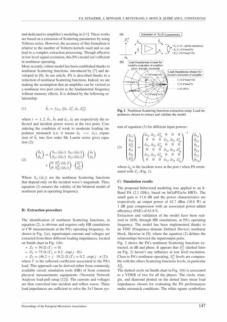
The identification of nonlinear Scattering functions, inequation (2), is obvious and requires only HB simulationsor CW measurements at the PA’s operating frequency. Asshown in Fig. 1(a), input/output currents and voltages areextracted from three different loading impedances, locatedon Smith chart in Fig. 1(b):
– Z1 = 50 � (�1 = 0)
– Z2 = 75 � (�2 = 0.2 · exp( j · 0))
– Z3 = (46.2 + j · 19.2) � (�3 = 0.2 · exp( j · π/2))
where � is the reflected coefficient associated to the PA’sload. This approach can be derived either from commonlyavailable circuit simulation tools (HB) of from commonphysical measurements equipments (Vectorial NetworkAnalyser load-pull setup [12]). The currents and voltagesare then converted into incident and reflect waves. Threeload impedances are sufficient to solve the 3x3 linear sys-
Fig. 1. Nonlinear Scattering functions extraction setup. Load im-pedances chosen to extract and validate the model.
tem of equation (3) for different input powers:
(3)
⎛⎜⎜⎜⎜⎜⎜⎝
S11S12
S�12
S21S22
S�22
⎞⎟⎟⎟⎟⎟⎟⎠
=
⎛⎜⎜⎜⎜⎜⎜⎜⎝
a11 a21 a∗21
0 0 00 0 0 a11 a21 a∗
21a12 a22 a∗
220 0 0
0 0 0 a12 a22 a∗22
a13 a23 a∗23
0 0 00 0 0 a13 a23 a∗
23
⎞⎟⎟⎟⎟⎟⎟⎟⎠
−1
·
⎛⎜⎜⎜⎜⎜⎜⎜⎝
b11
b21
b12
b22
b13
b23
⎞⎟⎟⎟⎟⎟⎟⎟⎠
where aij is the incident wave at the port i when PA termi-nated with Z j (Fig. 1).
C) Simulation results
The proposed behavioral modeling was applied to an S-Band PA (2.1 GHz), based on InGaP/GaAs HBTs. Thesmall gain is 11.6 dB and the power characteristics arerespectively an output power of 42.7 dBm (18.6 W) at1 dB gain compression with an associated power-addedefficiency (PAE) of 63.8 %.Extraction and validation of the model have been real-ized in ADS, through HB simulations, at PA’s operatingfrequency. The model has been implemented thanks toan FDD (Frequency-domain Defined Device) nonlinearblock, likewise in [9], where the equation (2) defines therelationships between the input/output ports.Fig. 2 shows the PA’s nonlinear Scattering functions ex-tracted, in dB and phase. It appears that S�
i j (dashed lineson Fig. 2) haven’t any influence in low level excitation.Close to PA’s nonlinear operating, S�
i j levels are compara-ble with the others Scattering functions levels, in particularS�
22.The dashed circle on Smith chart in Fig. 1(b) is associatedto a VSWR of two for all the phases. The circle, trian-gle, and diamond plotted on the dotted lines mean loadimpedances chosen for evaluating the PA performancesunder mismatch conditions. The white square symbolizes
Proceedings of the European Microwave Association 147

BEHAVIORAL MODELING OF POWER AMPLIFIER FOR RADAR APPLICATIONS
Fig. 2. PA’s nonlinear scattering functions (dB) and (phase) ver-sus a1.
the optimal load equal to 50 �. Fig. 3 shows the com-parison between circuit-level simulation and our modelat operating frequency, when the PA is respectively con-nected to its optimal load and to the three different loads(VSWR = 2).We notice that, when the output impedance is equal to oneof the load used to PA’s identification (like 50 �), circuitand model responses are identical, because of the system(3) is solved from incident/reflect waves measured at theseimpedances.For other loads which belong to the disc of VSWR = 2,errors are almost null. In the worst conditions, (� =1/3·exp( j ·3π/2)) the upper gain deviation between modeland circuit simulation is close to 0.3 dB at −4 dB com-pression. These results demonstrated the model abilitiesfor predicting PA’s behavior until a VSWR of two.
III. Black-box modelingfor accurate predictions of PA’s performancesA) From operating frequency to amplifier’sbandwidth
The model’s capabilities are extended to PA’s operatingbandwidth, in order to take into account the PA’s HF mem-ory effects [8, 13, 14], which are significant in Radar ap-
Fig. 3. Simulation-based behavior model (solid lines) comparedto circuit. Gain (dB) and AM-PM (degrees) versus input powerin dBm for PA terminated with the different loads symbolized onFig. 1(b).
plications. The nonlinear Scattering functions extractionis recurred for several frequencies which belong to PA’sbandwidth. Equation (4) defines the PA’s model:
(b1
b2
)=
(S11 (|a1|, �) S12 (|a1|, �)
S21 (|a1|, �) S22 (|a1|, �)
)·(
a1a2
)
+(
0 S�12 (|a1|, �)
0 S�22 (|a1|, �)
)·(
a∗1
a∗2
)(4)
where � is the frequency offset from carrier.
B) Advanced system environment:Scilab/Scicos - Modelica
The system simulation environment chosen, Scilab/Scicos,is an open-source alternative to Matlab/Simulink. Scicosis a toolbox in the free scientific software package for nu-merical computations available in Scilab [15]. It is ded-icated to the modeling and simulation of dynamic sys-tems. Several RF simulation tools were implemented inScicos, like numerical transmission chains [16], accurateunilateral black-box models [17] and a co-simulation in-terface between circuit and system simulator. The choice
148 Proceedings of the European Microwave Association
F.X. ESTAGERIE, A. BENNADJI, T. REVEYRAND, S. MONS, R. QUERE AND L. CONSTANCIAS
of the system simulator Scicos was driven by the capabil-ity to couple Scicos and Modelica, which is a freely avail-able object-oriented language [18, 19]. Modelica is usedfor solving physical problems, based on DAE system (Dif-ferential Algebraic Equation) [20]. Indeed, bilateral mod-eling implies that a simulation environment can solve im-plicit systems, i.e. DAE system in the following form:
(5) F (x, x, y, y, t) = 0
Considering the second equation given in (4), we canrewrite the real and imaginary parts of the output waveb2 (where ai and bi are time dependent) :
(6)
⎧⎪⎪⎪⎪⎪⎪⎪⎪⎪⎨⎪⎪⎪⎪⎪⎪⎪⎪⎪⎩
b�2 = S�
21 (|a1| , �) · a�1 − S�
21 (|a1| , �) · a�1
+ S�22 (|a1|, �) · a�
2 −SI22 (|a1|, �) · a�
2
+ S�22
�(|a1|, �) · a�
2 +S�22
�(|a1|, �) · a�
2b�
2 = S�21 (|a1| , �) · a�
1 + S�21 (|a1| , �) · a I
1
+ S�22 (|a1|, �) · a�
2 +S�22 (|a1|, �) · a�
2
+ S�22
�(|a1|, �) · a�
2 −S�22
�(|a1|, �) · a�
2
A more convenient form of equation (6) is obtained byconsidering the reflected � coefficient associated to thePA’s load:
(7) a2(t) = � · b2(t)
In this case, equations (6) and (7) takes the following form:
(8) F(
a1(t), b2(t), t)
= 0
In order to simplify diagram construction, acausal (or im-plicit) blocks, i.e. blocks with non-oriented input/outputports, are integrated in Scicos. Indeed, these blocks arewritten obviously in Modelica language but external func-tions can be called. Note that, explicit and implicit blockscan be used simultaneously in the same Scicos diagram (inthis case, DAE solver is chosen). The compilation of Sci-cos diagrams generates a Modelica netlist that describesthe entire diagram in a temporary file. The Modelica com-piler, called Modelicac, receives this netlist and generatesa usable C program for Scicos.Equation (4), in form of equation (6), has been imple-mented in Modelica where Si j (|a1|, �) are expandedthanks to polynomials approximation:
(9) Si j (|a1|, �) =N∑
n=0
αn (|a1|) · (�)n
where i, j = 1, 2, αn are the polynomials coefficients and� a frequency parameter of this model.This interpolation method has been chosen considering thenumerical implementation of the model in system simu-lator and on the other hand because it offers a sufficientaccuracy compared to more effective but more complexinterpolation methods.In our case, 9 frequencies are sufficient to describe the fullPA’s operating bandwidth (400 MHz). The polynomialsdegrees are weak, ranging between 3 and 5; 3 and 4 for the
“classical” Scattering functions (S11, S12, S21, S22) and 5for
(S�
i j
)whose variations are strongly nonlinear.
C) Simulation results in time domain at system level
Fig. 4 illustrates the principle, used in Scicos, in orderto simulate the PA’s model in the time domain. Explicitblocks (Scicos Blocks) are dedicated to signal processing:generating excitation signals and processing simulation re-sults. Implicit blocks (Modelica blocks) are dedicated tosolving the bilateral physical system.
Fig. 4. Simulation of physical systems in Scicos environment.
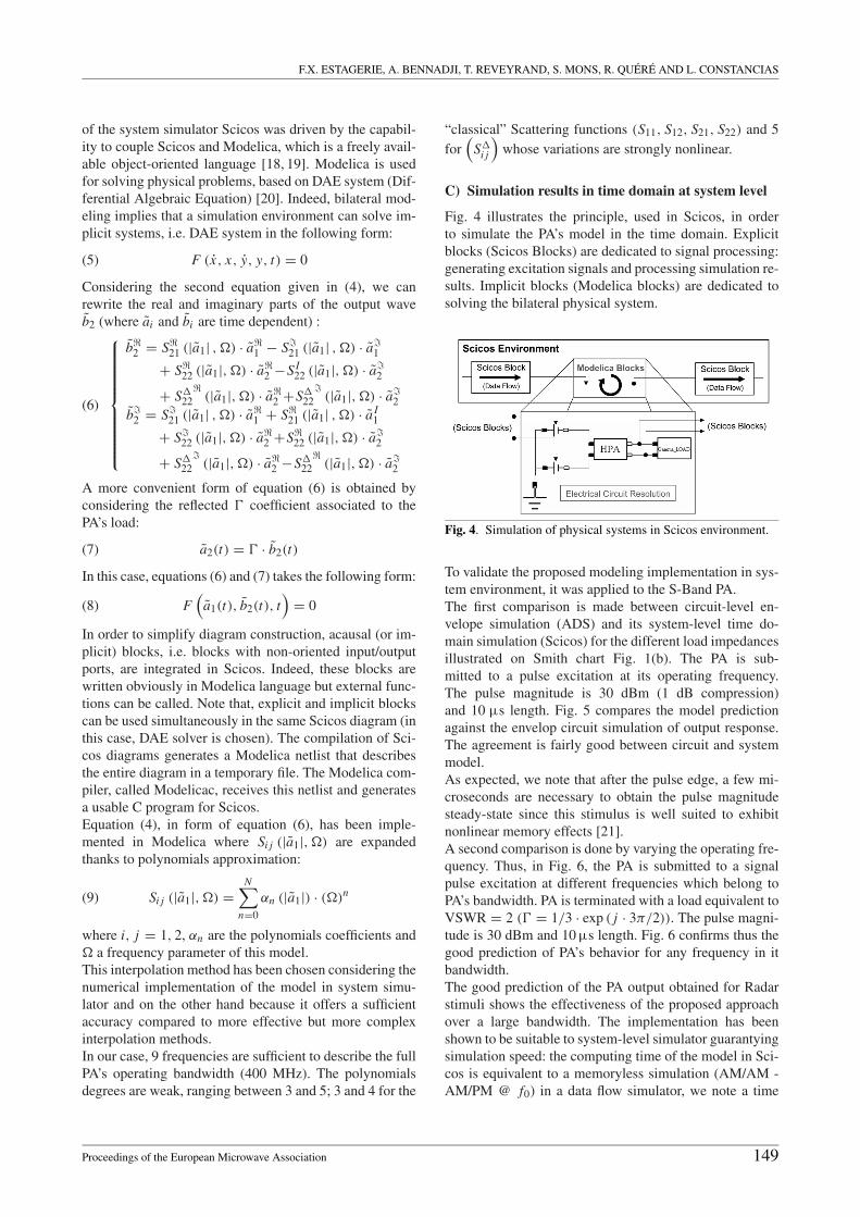
To validate the proposed modeling implementation in sys-tem environment, it was applied to the S-Band PA.The first comparison is made between circuit-level en-velope simulation (ADS) and its system-level time do-main simulation (Scicos) for the different load impedancesillustrated on Smith chart Fig. 1(b). The PA is sub-mitted to a pulse excitation at its operating frequency.The pulse magnitude is 30 dBm (1 dB compression)and 10 μs length. Fig. 5 compares the model predictionagainst the envelop circuit simulation of output response.The agreement is fairly good between circuit and systemmodel.As expected, we note that after the pulse edge, a few mi-croseconds are necessary to obtain the pulse magnitudesteady-state since this stimulus is well suited to exhibitnonlinear memory effects [21].A second comparison is done by varying the operating fre-quency. Thus, in Fig. 6, the PA is submitted to a signalpulse excitation at different frequencies which belong toPA’s bandwidth. PA is terminated with a load equivalent toVSWR = 2 (� = 1/3 · exp ( j · 3π/2)). The pulse magni-tude is 30 dBm and 10 μs length. Fig. 6 confirms thus thegood prediction of PA’s behavior for any frequency in itbandwidth.The good prediction of the PA output obtained for Radarstimuli shows the effectiveness of the proposed approachover a large bandwidth. The implementation has beenshown to be suitable to system-level simulator guarantyingsimulation speed: the computing time of the model in Sci-cos is equivalent to a memoryless simulation (AM/AM -AM/PM @ f0) in a data flow simulator, we note a time
Proceedings of the European Microwave Association 149
BEHAVIORAL MODELING OF POWER AMPLIFIER FOR RADAR APPLICATIONS
Fig. 5. Simulation-based behavior model (solid lines) comparedto circuit time response. Output voltage magnitude (V) and phase(degrees) versus time in μs for PA terminated with the differentloads show on Smith chart in Fig. 1(b).
gain up to 150 compares to the envelop circuit simulationlevel.
IV. Topologic modeling for an efficient designof PA’s sub-circuitBlack-box modeling is very useful for estimating cir-cuit performances on system level. Unfortunately, this ap-proach cannot be used to investigate nonlinear phenomenainvolved in critical circuits such as multistage PAs used inthe emission chain. There is an interest on identificationof electrical and electro-thermal causes of memory sincethis phenomena are as a majority located in particularsub-circuits such as active cells, biasing or matching net-works. This novel modeling approach differentiates alsothe passive (order reduction) and active (nonlinear Scatter-ing functions) parts and thus allows an efficient modelingof each sub-circuit effectively. Thereby, this approach isuseful to impact circuit performances at system level butalso to provide an optimal designing of each sub-circuit.Hence, topologic modeling establishes a bilateral commu-nication between circuit and system level, allowing an ef-ficient aided design of PAs.
Fig. 6. Simulation-based behavior model (solid lines) comparedto circuit time response. Output voltage magnitude (V) and phase(degrees) versus time in μs for PA terminated with load equiva-lent to VSWR = 2 ((40-j.30)�) at different frequencies whichbelong to PA’s bandwidth.
A) Model theory
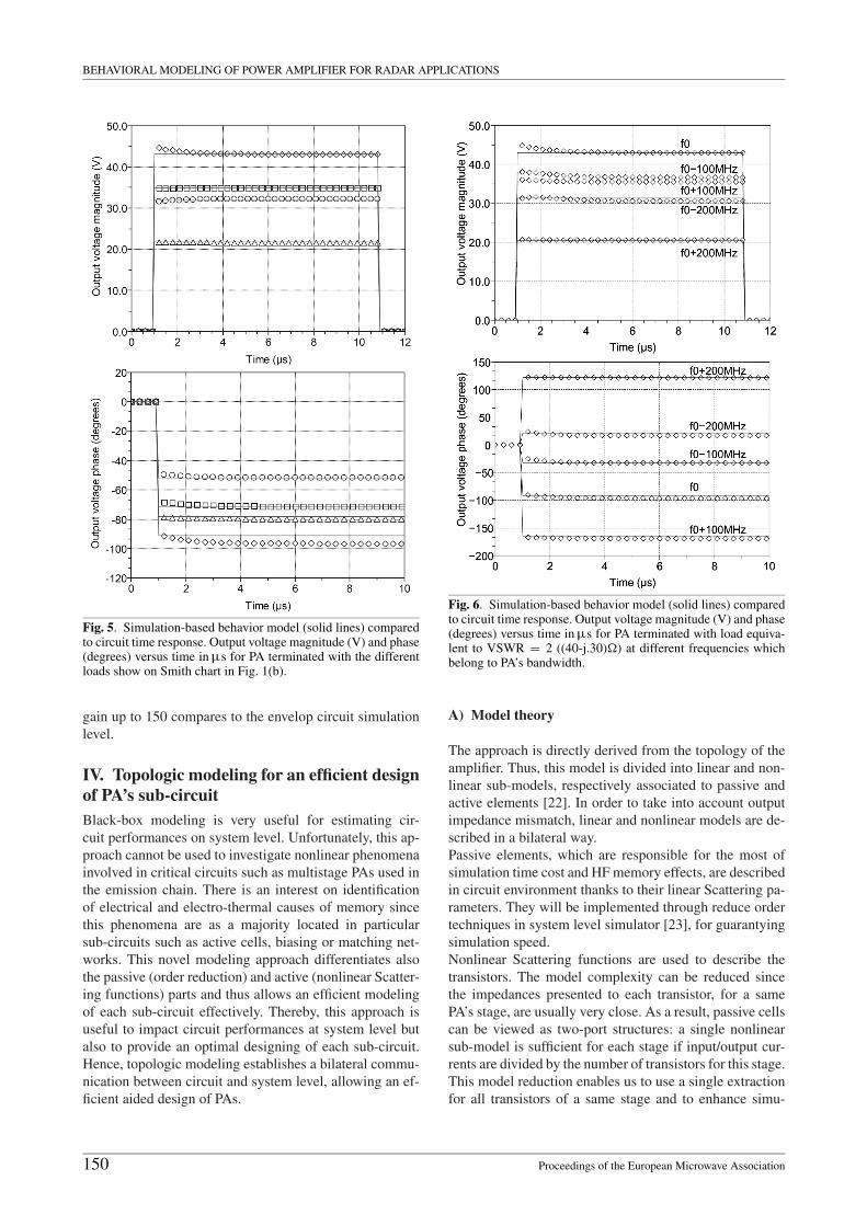
The approach is directly derived from the topology of theamplifier. Thus, this model is divided into linear and non-linear sub-models, respectively associated to passive andactive elements [22]. In order to take into account outputimpedance mismatch, linear and nonlinear models are de-scribed in a bilateral way.Passive elements, which are responsible for the most ofsimulation time cost and HF memory effects, are describedin circuit environment thanks to their linear Scattering pa-rameters. They will be implemented through reduce ordertechniques in system level simulator [23], for guarantyingsimulation speed.Nonlinear Scattering functions are used to describe thetransistors. The model complexity can be reduced sincethe impedances presented to each transistor, for a samePA’s stage, are usually very close. As a result, passive cellscan be viewed as two-port structures: a single nonlinearsub-model is sufficient for each stage if input/output cur-rents are divided by the number of transistors for this stage.This model reduction enables us to use a single extractionfor all transistors of a same stage and to enhance simu-
150 Proceedings of the European Microwave Association
F.X. ESTAGERIE, A. BENNADJI, T. REVEYRAND, S. MONS, R. QUERE AND L. CONSTANCIAS
lation time cost. Fig. 7 shows an example of the model’stopology. In the following, the paper focuses on the mod-eling of transistors.
Fig. 7. Topologic approach : assembly of linear and nonlinearsub-models, based on the same topology of design circuit.
B) Nonlinear Scattering functions balancedin frequency
To extend prediction capabilities to PA’s operating band-width, in addition to PA’s HF memory effects caused bylinear sub-circuits, the frequency’s dispersion of transis-tor must be considered. An acceptable solution leads toconsider |a1| and � as independent variables and thusto apply coefficient ci j (�) (normalized to one), where� = 2π ( f − f0) is the pulsation shift with respect toreference ω0. These coefficients are evaluated for a fixedvalue of |a1| according to a small signal regime:
(10) ci j (�) = Si j (|a1| , �)
Si j (|a1| , �0)
∣∣∣∣|a1|=constant
Applying equations (10) into (2), we obtain:
(b1
b2
)=
(S11 (|a1|) · c11(�) S12 (|a1|) · c12(�)
S21 (|a1|) · c21(�) S22 (|a1|) · c22(�)
)·(
a1a2
)
+(
0 S�12 (|a1|) · c
′12(�)
0 S�22 (|a1|) · c
′22(�)
)·(
a∗1
a∗2
)
(11)
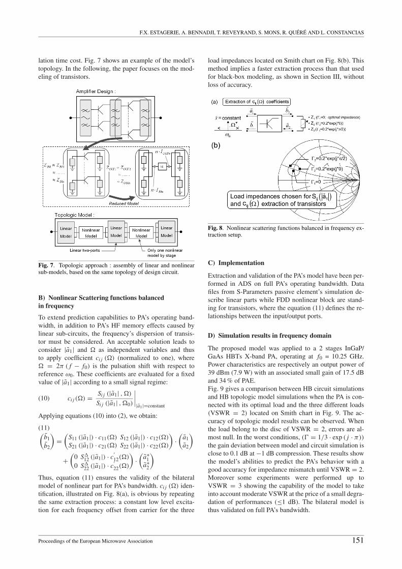
Thus, equation (11) ensures the validity of the bilateralmodel of nonlinear part for PA’s bandwidth. ci j (�) iden-tification, illustrated on Fig. 8(a), is obvious by repeatingthe same extraction process: a constant low level excita-tion for each frequency offset from carrier for the three
load impedances located on Smith chart on Fig. 8(b). Thismethod implies a faster extraction process than that usedfor black-box modeling, as shown in Section III, withoutloss of accuracy.
Fig. 8. Nonlinear scattering functions balanced in frequency ex-traction setup.
C) Implementation
Extraction and validation of the PA’s model have been per-formed in ADS on full PA’s operating bandwidth. Datafiles from S-Parameters passive element’s simulation de-scribe linear parts while FDD nonlinear block are stand-ing for transistors, where the equation (11) defines the re-lationships between the input/output ports.
D) Simulation results in frequency domain
The proposed model was applied to a 2 stages InGaP/GaAs HBTs X-band PA, operating at f0 = 10.25 GHz.Power characteristics are respectively an output power of39 dBm (7.9 W) with an associated small gain of 17.5 dBand 34 % of PAE.Fig. 9 gives a comparison between HB circuit simulationsand HB topologic model simulations when the PA is con-nected with its optimal load and the three different loads(VSWR = 2) located on Smith chart in Fig. 9. The ac-curacy of topologic model results can be observed. Whenthe load belong to the disc of VSWR = 2, errors are al-most null. In the worst conditions, (� = 1/3 · exp ( j · π))
the gain deviation between model and circuit simulation isclose to 0.1 dB at −1 dB compression. These results showthe model’s abilities to predict the PA’s behavior with agood accuracy for impedance mismatch until VSWR = 2.Moreover some experiments were performed up toVSWR = 3 showing the capability of the model to takeinto account moderate VSWR at the price of a small degra-dation of performances (≤1 dB). The bilateral model isthus validated on full PA’s bandwidth.
Proceedings of the European Microwave Association 151
BEHAVIORAL MODELING OF POWER AMPLIFIER FOR RADAR APPLICATIONS
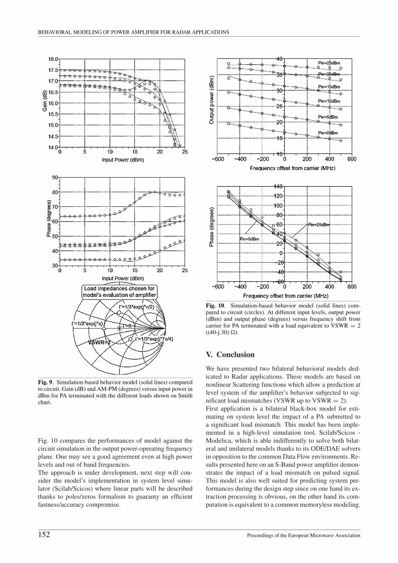
Fig. 9. Simulation-based behavior model (solid lines) comparedto circuit. Gain (dB) and AM-PM (degrees) versus input power indBm for PA terminated with the different loads shown on Smithchart.
Fig. 10 compares the performances of model against thecircuit simulation in the output power-operating frequencyplane. One may see a good agreement even at high powerlevels and out of band frequencies.The approach is under development, next step will con-sider the model’s implementation in system level simu-lator (Scilab/Scicos) where linear parts will be describedthanks to poles/zeros formalism to guaranty an efficientfastness/accuracy compromise.
Fig. 10. Simulation-based behavior model (solid lines) com-pared to circuit (circles). At different input levels, output power(dBm) and output phase (degrees) versus frequency shift fromcarrier for PA terminated with a load equivalent to VSWR = 2((40-j.30) �).
V. Conclusion
We have presented two bilateral behavioral models ded-icated to Radar applications. These models are based onnonlinear Scattering functions which allow a prediction atlevel system of the amplifier’s behavior subjected to sig-nificant load mismatches (VSWR up to VSWR = 2).First application is a bilateral black-box model for esti-mating on system level the impact of a PA submitted toa significant load mismatch. This model has been imple-mented in a high-level simulation tool, Scilab/Scicos -Modelica, which is able indifferently to solve both bilat-eral and unilateral models thanks to its ODE/DAE solversin opposition to the common Data Flow environments. Re-sults presented here on an S-Band power amplifier demon-strates the impact of a load mismatch on pulsed signal.This model is also well suited for predicting system per-formances during the design step since on one hand its ex-traction processing is obvious, on the other hand its com-putation is equivalent to a common memoryless modeling.
152 Proceedings of the European Microwave Association

F.X. ESTAGERIE, A. BENNADJI, T. REVEYRAND, S. MONS, R. QUERE AND L. CONSTANCIAS
Second application is a bilateral topologic model whichmakes it possible to predict system performances but alsoan efficient design of sub-circuits in order to decrease mar-gins taken on components specifications. This model, cur-rently implemented in ADS, is under development to ex-tend its capabilities to thermal and memory effects predic-tion.These models will be very useful in establishing predictiveperformances in radar applications, particularly to quan-
tify the impact of its operating on T/R modules, theyshould finally integrate the AESA radar simulation tools:ASTRAD and SAFAR.
AcknowledgementsThe authors wish to acknowledge CELAR (Centre d’Elec-tronique de l’ARmement) and DGA (French Defence andSecurity Agency) for technical and financial supports.
References
[1] Hommel, H.; Feldle, H.P.: Current status of Airborne activephased array (AESA) radar systems and future trends. Eu-ropean Microwave Conference, Amsterdam, Netherlands,2004, 1517-1520.
[2] Pedro, J.C.; Maas, S.A: A comparative overview of mi-crowave and wireless power-amplifier behavioral model-ing approaches. IEEE Trans. Microwave Theory and Tech-niques 53 (2005), 1150-1163.
[3] Soury, A.; Ngoya, E.; Nebus, J.M.: A new behavioral modeltaking into account nonlinear memory effects and tran-sient behaviors in wideband SSPAs. IEEE MTT-S Int. Mi-crowave Symp. Digest, June 2002, 853-856.
[4] Maziere, C.; Soury, A.; Ngoya, E.; Nebus, J.M.: A systemlevel model of solid state amplifiers with memory based ona non linear feedback loop principle. European MicrowaveConference, Paris, France 2005.
[5] Boumaiza, S.; Ghannouchi, F.M.: Thermal memory effectsmodeling and compensation in RF power amplifiers andpredistortion linearizers. IEEE Trans. Microwave Theoryand Techniques 51 (2003), 2427-2433.
[6] Mazeau, J.; Sommet, R.; Caban-Chastas, D.; Gatard, E.;Quee, R.; Mancuso, Y.: Behavioral thermal modelingfor microwave power amplifier design. IEEE Trans. Mi-crowave Theory and Techniques 55 (2007), 2290-2297.
[7] Verspecht, J.: Scattering functions for nonlinear behavioralmodeling in frequency domain. Fundamentals of NonlinearBehavioral Modeling: Foundations and Applications Work-shop, IEEE MTT-S Int. Microwave Symp., June 2003.
[8] Soury, A. ; Ngoya, E.; Rousset, J.: Behavioral modeling ofRF and microwave circuit blocks for hierarchical simula-tion of modern transceivers. IEEE MTT-S Int. MicrowaveSymp. Digest, June 2005, 975-978.
[9] Root, D.E.; Verspecht, J.; Sharrit, D.; Wood, J.; Cognata,A.: Broad-band poly-harmonic distortion (PHD) behavioralmodels from fast automated simulations and large-signalvectorial network measurements. IEEE Trans. MicrowaveTheory and Techniques 53 (2005), 3656-3664.
[10] Wiener, D.; Naditch, G.: A scattering variable approach tothe Volterra analysis of nonlinear systems. IEEE Trans. Mi-crowave Theory and Techniques 24 (1976), 422-433.
[11] Verbeyst, F.; Vanden Bossche, M.: VIOMAP, the S-parameter equivalent for weakly nonlinear RF and mi-crowave devices. IEEE Trans. Microwave Theory andTechniques 42 (1994), 2531-2535.
[12] Reveyrand, T.; Gasseling, T.; Barataud, D.; Mons, S.;Nebus, J.M.: A smart load-pull method to safely reach opti-mal matching impedances of power transistors. IEEE MTT-S Int. Microwave Symp. Digest, June 2007, 1489-1492.
[13] Vuolevi, J.H.K; Rahkonen, T.; Manninen, J.P.A.: Mea-surement technique for characterizing memory effects inRF power amplifiers. IEEE Trans. Microwave Theory andTechniques 49 (2001), 1383-1389.
[14] Ngoya, E.; Le Gallou, N.; Nebus, J.M.; Buret, H.; Reig,P.: Accurate RF and microwave system level modeling ofwide band nonlinear circuits. IEEE MTT-S Int. MicrowaveSymp. Digest, June 2000, 79-82.
[15] Nikoukhah, R.; Steer, S.: A dynamic system builder andsimulator, in User’s guide - Version 1.0. [Online] Available:http://www.inria.fr/rrr/rt-0207.html.
[16] Layec, A.; Bennadji, A.; Nallatamby, J.C.; Quere, R.;Ngoya, E.: Modeling of a communication chain compo-nents & principles of simulation in the Scilab/Scicos en-vironment. Proc. of the 2005 IEEE Conf. on Control Ap-plications, Toronto, Canada, August 2005, 1127-1133.
[17] Bennadji, A.; Layec, A.; Soury, A.; Mallet, A.; Ngoya, E.;Quere, R.: Modeling of a communication chain with im-plementation of a Volterra power amplifier model for effi-cient system level simulation. The European Conference onWireless Technology, October 2005, 101-104.
[18] Najafi, M.; Furic, S.; Nikoukhah, R.: SCICOS: a generalpurpose modeling and simulation environment. Proc. 4thInt. Modelica Conference, Hambourg, Germany, March2005, 367-374.
[19] The Modelica website [Online]. Available:http://www.Modelica.org.
[20] Najafi, M.; Nikoukhah, R.; Campbell, S.L.: ODE andDAE solvers in Scicos environment. Iasted Int. Conferenceon applied simulation and modeling, ASM2004, Rhodes,Greece, June, 2004.
[21] Bosch, W.; Gatti, G.: Measurement and simulation of mem-ory effects in predistortion linearizers. IEEE Trans. Mi-crowave Theory and Techniques 37 (1989), 1885-1890.
[22] Estagerie, F.X.; Reveyrand, T.; Mons, S.; Quere, R.; Con-stancias, L.; Le Helleye, P.: From circuit topology to behav-ioural model of power amplifer dedicated to radar applica-tions. IEEE Electronics Letters 43 (2007), 477-479.
[23] Casas, F.J.; Portilla. J.; Quere, R.; Mallet, A.; Villemazet,J.F.: Model-order reduction of linear and weakly nonlineartime-varying RF and microwave circuits. IEEE Trans. Mi-crowave Theory and Techniques 52 (2004), 2262-2273.
Proceedings of the European Microwave Association 153

BEHAVIORAL MODELING OF POWER AMPLIFIER FOR RADAR APPLICATIONS
Francois-Xavier Estagerie was born inFrance in 1981. He received the master re-search degree in 2004 from the LimogesUniversity, France. He is presently a Ph.D.student at the XLIM laboratory in the HighFrequency Components Circuits Signals andSystems department, Limoges University.His main interests are modeling and im-plementation of amplifier models in systemsimulator.
Abderrazak Bennadji was born in Chlef,Algeria, in 1975. He received the Electronicengineering Degree from University of Bl-ida, Algeria, in 1999, the Phd degree inelectronic from the University of Limoges.From 2006, he works in institute of mi-crowave and optical communications, Uni-versity of Limoges, where he is currently in-volved with modeling and implementationof the amplifier models in the system sim-ulators.
Tibault Reveyrand was born in 1974 inParis. He received a Ph.D. from the LimogesUniversity, France, in 2002. From 2002 to2004, he was postdoctoral scientist with theCentre National d’Etudes Spatiales (CNES)(French Space Agency). In 2005, he becamea contractual engineer at the Centre Na-tional de la Recherche Scientifique (CNRS)with XLIM (formerly IRCOM), Limoges,France. His main research interests includethe characterization and the modeling of RF
and microwave non-linear components.
Sebastien Mons was born in Limoges(France) in 1970. He received the Ph.D.Degree in Electronics from the Univer-sity of Limoges in 1999. He joined theMicrowave Laboratory of the CNES ofToulouse, France, in 1999. Since October2001, he is a researcher of the FrenchCNRS at XLIM institute, Limoges univer-sity. His main research interests include sys-tem level modeling and nonlinear analysis ofmicrowaves circuits.
Raymond Quere (senior member IEEE)received the electrical engineering degreefrom ENSEEIHT Toulouse, France in 1976,the French aggregation in applied physics in1978 and a Ph.D. degree from Limoges Uni-versity in 1989. In 1992 he was appointedfull professor at the Limoges Universitywhere he leads the nonlinear high frequencydevices, circuits and systems research groupat XLIM-CNRS laboratory. His main fieldof interest is in the area of nonlinear device
and circuit modeling with a particular emphasis on nonlinear phenom-ena such as stability in power amplifiers. He is involved in a number oftechnical program committees and serves as a reviewer for several jour-nals. In 2005 he was appointed as the general Chairman of the EuropeanMicrowave Week in Paris.
Laurent Constancias received in 2003the degree in electrical and computer en-gineering (Ecole Superieure d’Electricite).Between 2003-2007, he was microwave en-gineer at CELAR (French MoD, DGA).Since 2007, he joined research and de-velopment radar engineer at ONERA, thefrench aerospace lab. His main interests in-clude microwave components, propagation,signal processing applied to radar and nu-meric communications, modeling and nu-
meric simulation.
154 Proceedings of the European Microwave Association