behaviour of steel plate shear walls with ... behaviour of steel plate shear walls with...
TRANSCRIPT

1
BEHAVIOUR OF STEEL PLATE SHEAR WALLS WITH
BUCKLING-RESTRAINED WEB PANELS
Irena Hadzhiyaneva 1 and Borislav Belev
2
ABSTRACT
A scaled specimen representing single-storey partially-composite steel plate shear wall was tested
under cyclic loading. The slender steel web panel had a single-sided reinforced concrete encasement
attached with headed shear studs in order to prevent the shear buckling and tension-field action of the
slender web when subjected to lateral seismic forces. A specific feature of the tested specimen was the
use of semi-rigid beam-to-column connections and purposely made gaps between the boundary steel
frame members and the concrete encasement.
The testing was conducted using the recommended testing procedure of ECCS and showed that
the specimen has stable hysteretic behaviour and dissipative capacity superior to that of its pure steel
counterpart tested under the same conditions.
Parallel numerical simulations based on simplified and more refined nonlinear models were
carried out in order to provide insight into the complex interaction between the shear wall components.
Both experimental testing and numerical simulation revealed that the cyclic response of the specimen
was affected by the formation of local tension-field action in-between the shear stud rows, which is an
indication that the seismic codes shall improve their provisions for the design of reinforced-concrete
encasement and its shear stud connection to the slender steel web panel.
INTRODUCTION
Steel and composite shear walls have been used for seismic applications in USA, Canada, Japan and
other countries for more than 40 years now. A typical steel plate shear wall (SPSW) consists of
horizontal and vertical boundary framing members and slender infill panels (webs). The most recent
projects entirely avoid the use of web stiffeners and rely on the post-critical tension-field action of the
infill panels. The composite shear walls (CSW) have a single- or double-sided concrete encasement of
the slender infill panels which inhibits their buckling under wind and seismic action. The reliability
and robustness of this relatively new structural system have been proven in several strong earthquakes.
It has good ductility and stable energy dissipation capacity combined with reduced self-weight in
comparison with the conventional reinforced concrete shear walls. Eurocode 8 (CEN, 2004) contains
design provisions for CSWs only. However, the contribution of the concrete encasement to lateral
strength and stiffness is neglected, and this implies that the encasement is expected to act as a
buckling-restraining “shell” for the slender steel infill panels. The paper presents the experimental and
1 Assistant-Prof., Dr., University of Architecture, Civil Engineering and Geodesy, Sofia, Bulgaria,
[email protected] 2 Prof. Dr., University of Architecture, Civil Engineering and Geodesy, Sofia, Bulgaria, [email protected]

2
numerical evaluation of a scaled partially-composite single-storey specimen with purposely provided
gaps between the concrete encasement and the boundary steel framing. The main objectives of the
study were to investigate the resistance, ductility and energy dissipation capacity of this specific CSW-
prototype with a buckling-restrained infill panel and compare its performance with that of the bare-
steel counterparts.
1. DESCRIPTION OF THE SPECIMENS AND TEST SET-UP
Two scaled specimens of SPSWs (W1 and W2) and one of CSW (W3) with almost identical
dimensions of steel structure were fabricated. It was planned to test the first one (W1) under
monotonic unidirectional loading and afterwards the other spesimens (W2, W3) under pseudo-static
cyclic loading with displacement control. The scale of the specimens was approximately 1:4 (Fig. 1).
Figure 1. Layout of tested spesimens: top – bare steel specimens; bottom – partially-composite specimen (W3)

I. Hadzhiyaneva and B. Belev 3
The boundary frame members (top beam, base beam and columns) have hot-rolled cross
sections of IPE200, IPE270 and HEB120, respectively. The infill panel was designed with 1,5 mm
thickness and S235 steel grade, but both the actual thickness and the steel properties deviated from the
design values.
The nominal slenderness of the web panel with 600x600 mm clear dimensions was therefore
600/1,5=400. The partially composite specimen W3 had a single-sided reinforced concrete encasement
with dimensions 520x520 mm and thickness 80 mm. The design grade of concrete was C20/25. The
reinforcing bars were 8 mm dia with 70 mm spacing in both directions. The shear connection between
the steel web panel and concrete encasement was made by means of bolted headed studs (M6, grade
5.6) with 75 mm spacing. Additional rectangular washers were used to prevent pullout of the studs and
tearing of thin web at stud attachments. In order to improve the ductility of the CSW specimen and
avoid direct interaction between the concrete encasement and boundary steel framing, the innovative
proposal of Astaneh-Asl (2002) was implemented. The encasement was separated from steel frame
members by leaving a 40 mm wide gap.
Due to limitations of the loading system it was decided to use pin connections at the column
bases. The beam-to-column joints were purposely made of semi-rigid and partial-strength type using a
couple of 12 mm thick fin-plates welded to beam web only. The fin plates were connected to the
column flange with full-penetration butt welds. The thin infill panel was connected to the boundary
frame members by 5 mm thick and 20 mm wide perimeter steel strips. Actually the W2 and W3-
specimens were fabricated after W1 was tested and the welding procedure for the thin infill panel was
improved in order to avoid premature connection failure observed during W1 testing. The initial visual
check of the specimens prior to their testing revealed that due to the small size of the infill panels and
large total length of the fillet welds, the thin infill plates did not show any sign of initial geometrical
imperfections in the form of out-of-flatness. Instead, they looked like “stretched”, most probably due
to residual biaxial tensile stresses induced by the welding. This kind of hidden “prestressing” was
suspected to influence the initial stiffness and onset of yielding of the specimens. The thickness of the
reinforced concrete encasement of W3-specimen was larger than the minimum values specified in
AISC (2005) and CEN (2004) for composite shear walls. The encasement and its reinforcement were
designed with extra overstrength in order to maintain well their stiffness and resistance during cyclic
testing. The same approach was followed in design of headed shear studs (M6), which had to provide
shear transfer and prevent web local buckling. The provisions of AISC (2005) were used for
estimating the required spacing b of shear studs:
653021000.51,11,1max
===
yv fEk
t
b (1)
For infill panel thickness t =1,5 mm the allowable stud spacing max 0,15.65 9,76b cm≤ = and
therefore for the W3-specimen b = 7,5 cm was chosen.
All specimens were tested in a vertical plane being oriented as short horizontal cantilevers with
the transversal loading applied along the axis of the top boundary beam (Fig. 2). For the testing
protocol (loading history) of W2 and W3 specimens it was decided to follow the general rules of the
ECCS procedure (ECCS, 1986). An important parameter in this procedure is the so-called reference
yield displacement yU which is further used for defining the displacement amplitude of the loading
cycles. Preliminary numerical studies indicated that the recommended bilinear approximation of the
nonlinear force-displacement diagram did not produce a realistic estimate of yU and the onset of
significant inelastic response for the bare-steel specimen (W2) was influenced both by the tensile
yielding of the infill panel at its post-buckling stage and inelastic rotations of the semi-rigid frame
joints. It was concluded that the “yield” displacement yU can be assumed in a rather broad range (3,0
to 4,5 mm). As the testing program was planned to continue with the more rigid partially-composite
specimen (W3) with concrete-encased infill panel, yU =3,0 mm was assumed in order to apply a
common loading history for the bare-steel (W2) and partially-composite (W3) specimens.

4
Figure 2. Test set-up: left - specimen W1 with actuator on the top; right - W3 specimen.
2. NUMERICAL MODELLING AND ANALYSIS
2.1. Simplified analysis approach
At the early stages of this research the so-called tension strip model proposed by Thorburn et al.
(1983) was used. It represents the diagonal tension field developed after buckling of the slender infill
panel as a series of inclined parallel pin-ended strips. The number of strips required for realistic
modelling depends upon the panel geometry, but in general 10 equally spaced strips per panel are
sufficient. This approach has been further verified against experimental results and included in the
Canadian Steel Design Code (CSA, 2001). It is also suggested as a suitable analysis model in the
Commentary of (AISC, 2005). The angle of inclination of the strips α measured from the vertical was
estimated to 44 degrees. Recently Sun et al. (2008) proposed a crossed strip model (Fig. 3), which
estimates well the shear resistance of buckling-retrained steel web panel by notional inclined tension
and compression strips. The compression resistance of the latter was assumed 20% of tension
resistance of the former and the elasticity modulus of compression strips was half of the tension strips
modulus. This innovative proposal was implemented in the simplified model of the W3-specimen.
This is essentially a plane frame model created in SAP2000 and subjected to static nonlinear pushover
analysis assuming lumped plasticity (N-hinges for the tension strips, M-N hinges for finite elements
representing the beam and columns, and nonlinear rotational springs for the beam-to-column
connections). In order to obtain the strength demand for capacity design of the boundary framing
members and connections, the yield strength of the tension strips was increased by the overstrength
factor ovγ = 1,25. Subsequently, the models of W2 and W3 specimens were updated to reflect the
actual infill panel thickness and yield strength prior to the testing. The beam-to-column joints were
assumed pinned in an auxiliary model used to estimate the contribution of the boundary frame to the
overall strength and stiffness.
2.2. Refined analysis approach
In order to better predict the nonlinear response and assess the accuracy of the simplified
approach, three-dimensional models were created in ANSYS v.10.0 program (SAS IP Inc., 1998). All
components of the test specimens were modelled with SHELL181 finite elements. The models can
account for the complex stress distribution at the frame joints and, in addition, allow for simulating the
initial imperfections of the slender infill panel. The pattern of the initial out-of-plane deformations
was assumed to correspond to the first buckling mode shape, with magnitude equal to 1/200 of the
panel span for W2 as recommended by Annex C of EN 1993-1-5 (CEN, 2007). The steel material was
modelled with bilinear stress-strain diagram with 1 % slope of the post-yield branch. For the W3-

I. Hadzhiyaneva and B. Belev 5
specimen with partially-composite infill panel two refined models were prepared. The first one
corresponds to completely restrained steel web panel with out-of-plane supports in each finite element
node of the web panel. The second model includes discrete out-of-plane supports only at locations
where shear studs were placed (Fig. 4). These supports realistically represent the strong and stiff
concrete encasement.
Figure 3. Simplified plane model of W3 Figure 4. Three-dimensional model with discrete
web panel supports
The capacity curves computed through static nonlinear pushover analysis for the approximate
plane models are shown in Fig. 5, while those corresponding to the refined models are shown in Fig. 6.
2.3. Estimation of the expected yield resistance of the specimens
The expected yield resistance of the bare-steel specimens without the contribution of the
boundary frame was calculated using an equation from (AISC, 2005):
=y ,w,SPSW ov y cf wV 0,5g f L t sin 2a , (2)
where wt is the thickness of the infill panel and cfL is its clear length between the interior column
flanges. The expected yield resistance including the contribution of the frame was assumed to be
= ÷y ,e ,SPSW y ,w,SPSWV ( 1,2 1,30 )V , (3)
The expected yield resistance of the partially-composite specimen without the contribution of
the boundary frame was calculated using an equation from (CEN, 2004):
=y ,w,CSW ov y cf wV 0,6 f L tγ =1,20 Vy,w,SPSW (4)
If the ratio of yield resistances given by (2) and (4) is considered the expected yield resistance
of partially-composite specimen including the contribution of the boundary frame is
Vy, e,CSW =1,20.1,25Vy,w,SPSW (5)
Vy, e.CSW = 1,25Vy,w,CSW (6)
For the nominal panel properties ( yf =235MPa and wt =1,5mm), assuming α ≈45o and
ovγ =1,25, and L=Lcf=600 mm the above equations predict y,w,SPSWV =132 kN and y,e,SPSWV ≈165 kN.
If the same characteristics are assumed for the W3 specimen, its estimated resistances
are y,w,CSWV =158,4 kN and y,e,CSWV ≈198 kN.

6
For the actual panel properties Eq. (2) and (3) predict for W2 ( yf =300MPa, wt =1,68mm)
y,w,SPSWV =151,2 kN and y,e,SPSWV ≈ 189 kN. For the W3 specimen ( yf =300MPa, wt =1,68mm)
y,w,CSWV =181,4 kN and y,e,CSWV ≈ 227 kN, respectively.
Figure 5. Capacity curves obtained for strip models of W1 (SPSW) and W3 (CSW) specimens.
(F1 corresponds to the response of steel boundary frame alone)
Figure 6. Capacity curves obtined for refined models of W1 (SPSW) and W3 (CSW) specimens.
(F1 corresponds to the response of steel boundary frame alone)
The approximate strip models for bare-steel and partially-composite specimens were developed
based on center-to-center span length of 720 mm, which leads to yield resistance estimates different
from those calculated with Eq. (2) - (6). Based on the results of the numerical analyses, the frame
boundary members were designed for the internal forces and ultimate base shear derived from the
static nonlinear solution of the 2D-model with pinned beam-to-column joints corresponding to lateral
displacement maxU = 50 mm.
3. EXPERIMENTAL TESTING OF SPECIMENS
The experimental investigation of W1 and W2 specimens was reported in detail in
(Hadzhiyaneva and Belev, 2011). As this study is focused on the performance of the CSW specimen
(W3), the information given bellow about SPSW-specimens (W1 and W2) is only for comparison.
I. Hadzhiyaneva and B. Belev 7
3.1. Monotonic test of W1 and cyclic test of W2 specimens
During the experiment the specimens showed high resistance, stiffness and extremely stable
behaviour. This behaviour was observed despite of cracks formation in the bottom corners of web
panels (W1 and W2) and failure of the welded connection between the infill plate and perimeter
connection strip (W1). The structures reached their peak load level at Fmax= 235 kN (interstorey drift
ratio IDR ≈ 2,2 %) for W1 and for W2 - Fmax = 220 kN (IDR ≈ 1,4 %) and 260 kN (IDR ≈ 2.2 %) in
the positive and negative directions, respectively. The testing of W1 was terminated at force level Fu =
219 kN (IDR ≈ 3,3 %) due to the drastic increase of the rupture lengths at the infill plate corner and
signs of out-of-plane buckling of the top beam. W2 reached its ultimate IDRs equal to +2,2 % and -3,3
%, respectively, when crack developed in the weld connecting the fin plate with the column, which
was considered a global structure collapse . Prior to this limit state three more cracks developed in the
corners of web panel, probably due to low cyclic fatigue.
The ductility factors ∆µ and the system overstrength factors Ω were estimated as follows:
For W1 specimen:
=∆µ yu UU=∆µ = 27,7/5,6 = 4,95 ≈ 5,0 and yu FF=Ω = 235/158,5 = 1,48 ≈ 1,5 (7)
For W2 specimen:
yu UU=∆µ =8,2/5,1 = 3,6 and - yu UU=∆µ = 27,8/4,4 = 6,3 (8)
yu FF=Ω+ = 235/162,2 = 1,47 and yu FF=Ω− = 260/140,4 = 1,85 (9)
The values used for yU and related yF in Eq. (7)-(9) are the true values taken from the test
data, not from bilinear approximating diagrams. The hysteretic response of the specimen was stable
despite that some pinching of the loops was observed. It could be explained with the accumulation of
residual out-of-plane panel deformations and semi-rigid behaviour of the frame joints.
The maximum measured rotation of the beam-to-column joints of both specimens were 1,8 %,
which exceeds the limit required by AISC (2005), equal to 1 %.
3.2. Cyclic test of W3 - CSW specimen
The specimen underwent 17 full cycles of load reversal, and about 9 after yielding. First crack
developed in the perimeter connection strip during the cycle corresponding to 2/3Uy. In the first of the
three cycles with displacement amplitude 4Uy (twelfth cycle with interstorey drift ratio IDR ≈ 1,4 %)
web buckled in a free area between the strip and adjacent stud row. Afterward buckling spread and
formed local tension fields in-between the stud rows. Simultaneously second rupture developed in web
corner followed by third and fourth cracks in the other corners respectively in fourteen (IDR ≈ 1,4 %)
and fifteen (first cycle to 6Uy - IDR ≈ 1,4 %) cycles. It was accompanied by a perceivable amplitude
increase of out-of-plane deformation which transformed in a diagonal pattern as shown in Fig. 7.
During the last cycle with this amplitude (IDR ≈ 1,4 %), simultaneous cracking in the welds between
the fin plates and column flanges in both frame joints began to develop, and this was considered an
indication of overall limit state.
The closer investigation of the strain histories recorded at key locations of the specimen
revealed that the tensile yielding of the infill panel occurred almost simultaneously with the yielding in
bending of the fin-plates connecting the top beam to the columns. Afterwards, the overall stiffness of
the shear wall was severely reduced not only by the plastic deformations but also due to the ruptures at
the bottom corner of the panel tension field. The maximum measured rotation of the beam-to-column
joint was 1,8 %, which exceeds the limit required by AISC (2005), equal to 1 %.
Despite of the severe damages the specimen maintained its resistance up to the load levels
Fmax=220 kN and 240 kN in the positive and negative directions, respectively (Fig. 7). The ultimate
IDRs reached during the cyclic testing were +2,2 % and -3,3 %, respectively.
The ductility factors ∆µ and the system overstrengths Ω were estimated as follows:

8
+µ∆=Uu/Uy=19,6/3,3=5,9 ≈6 and −µ∆=Uu/Uy=20,9/4,2=4,98 ≈5 (10)
+Vu/Vy=+αu/αy=+241/141,3=1,71 and −Vu/Vy=-αu/αy=-270/152,1=1,78 (11)
After comparing of the data from the gauges on the semi-rigid joints and web panel it was
concluded that the web yielded before the fin plates. They started yielding in the first cycle with
displacement amplitude Umax=±6 mm, and yielded completely in the first cycle with Umax=±12 mm.
The maximum measured rotation of the beam-to-column were 1,5 %, which exceeds the required by
AISC (2005) minimum of 1 %. The local damage pattern at the vicinity of shear studs is shown in Fig.
8. The cyclic respons of the partially-composite specimen is illustrated on Fog. 9
Figure 7. W3-specimen after test completion Figure 8. Detail of web panel after removing
bolted shear studs
Figure 9. Hysteretic response of W3 specimen at displacement magnitude 6 yU
3.3. Conclusions for behaviour of W3 specimen under cyclic loading and comparison of
results for W3 and W2 specimens
Expectedly the W3 specimen dissipated more energy than W2 because of shear action of CSW
in contrast to tension field action in post-critical stage of SPSW. This was observed despite of local
buckling in the corner areas of W3. The comparison between two specimens showed one more
important advantage of composite shear wall – the pinching effect was negligible as can be seen in
Fig.9. Hysteretic behavior of W3 was stable without unexpected degradation of resistance and
stiffness which means that structural detailing was reasonable and the leaved gap between the steel
frame and reinforced concrete encasement of infill panel was sufficient. However, unexpected local
web buckling caused reduction of the W3 resistance so that it was higher than the resistance of W2
only by 6 to 10 %. This unfavourable effect was mentioned in Ziemian et al. (2010), too. The
conclusion is that the design provision of AISC (2005) presented by Eq. 1 for the shear stud

I. Hadzhiyaneva and B. Belev 9
arrangement is not perfect, especially when single sided encasement is used. The test results indicated
that the behavior of CSW-specimen is close to SPSW-specimen, but without clear pinching effect. The
overall ductility of bare-steel and partially-composite specimens under cyclic loading is also very
similar according to Fig. 10. The reported previously by Hadzhiyaneva and Belev (2011) effect of
hidden “prestressing” of web panel definitely influenced the initial stiffness and onset of yielding of
the both specimens –W2 and W3. As a result no pronounced yielding points can be determined on
their experimental load-displacement diagrams.
Figure 10. Ductility versus storey drift of SPSW specimen W2 and CSW specimen W3
4. COMPARISON OF EXPERIMENTAL AND NUMERICAL RESULTS
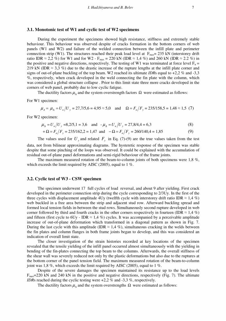
Fig. 11 and 12 compare the test-obtained force-displacement relationships with the numerical
predictions. In general, the FE-models and static nonlinear analyses can well estimate the ultimate
resistance of the specimens. As a general observation, the numerical models predict larger initial
stiffness. They, however, do not account for the residual welding stresses, which according to the
visual check of the infill panels prior to the testing, create an initial biaxial tension stress field. The
summation of these residual stresses with the stresses induced by the applied loading could result in
delay of the initial buckling, but also in earlier tensile yielding.
Figure 11. Comparison of results from simplified SAP models and testing of W3
10
Figure 12. Comparison of results from refined ANSYS models and testing of W3
5. CONCLUDING REMARKS
The experimental testing showed that the scaled SPSW- and CSW-specimens have good
ductility and stable hysteretic behaviour. The CSW-specimen with a buckling-restrained infill panel
performed better due to its shear action compared to post-critical tension field action of SPSW with
bare-steel web panel. The gaps left between the steel frame and concrete encasement seem to have
contributed to CSW ductility. As a whole the shear studs were not sufficient to ensure reliable out-of-
plane support of the slender web because because local web buckling was observed. The semi-rigid
frame joints exhibited adequate rotational capacity and could be considered a reasonable detailing
option for the real design applications if the beams are secured against lateral-torsional buckling.
The authors gratefully acknowledge the funding provided by CNIP of UACEG, Sofia for the
experimental part of this research.
REFERENCES
AISC (2005) Seismic Provisions for Structural Steel Buildings, American Institute of Steel Construction
Astaneh-Asl A (2002) Seismic Behavior and Design of Composite Steel Plate Shear Walls, Steel Tips Report,
SSEC, Moraga
Astaneh-Asl A (2001) Seismic Behaviour and Design of Steel Shear Walls, Steel Tips Report, SSEC, Moraga
CEN (2007) EN 1993-1-5, Eurocode 3, Design of steel structures, Part 1-5: Plated structural elements
CEN (2004) EN 1998–1, Eurocode 8: Design of structures for earthquake resistance, Part 1: General rules,
seismic actions and rules for buildings
CSA (2001) CAN/CSA S16-01, Limit State Design of Steel Structures, Canadian Standards Association
Driver R, Kulak G, Kennedy D, Elwi A (1997) Seismic Behaviour of Steel Plate Shear Walls, Structural
Engineering Report 215, University of Alberta, Canada
ECCS (1986) Recommended Testing Procedure for Assessing the Behaviour of Structural Steel Elements Under
Cyclic Loads, ECCS Publication No. 45
Hadzhiyaneva I and Belev B (2011) “A Study on the behaviour of steel plate shear walls under monotonic and
cyclic loading”, Proc. of EUROSTEEL’2011, 6th Eur. Conf. on Steel and Composite structures,
Budapest, Hungary
Hadzhiyaneva I and Belev B (2007) “European and North American provisions for design of steel and composite
shear walls”, International Symposium on Seismic Risk Reduction, Bucharest, Romania
SAS IP Inc. (1998) ANSYS Theory Reference
Sun FF, Liu GR, Li GQ (2008) “An Analytical Model for Composite Steel Plate Walls”, Proceedings of 14th
World Conference of Earthquake Engineering, Beijing, China
Thorburn LJ, Kulak GL, Montgomery CJ (1983) Analysis of Steel Plate Shear Walls, Structural Engineering
Report 107, University of Alberta, Canada
Zhao Q and Astaneh-Asl A (2004) “Cyclic Behaviour of Traditional and Innovative Composite Shear Walls”, J.
of Structural Engineering, ASCE, vol. 130 (2), pp 271–284
Ziemian R, ed. (2010) Guide to Stability Design Criteria for Metal structures, Sixth Edition, Wiley & Sons