belt and screw type linear modules - industrieplus€¦ · standard assembly solutions . 5. sizing...
TRANSCRIPT

Belt and screw type linear modules

This document replaces all previous editions. Due to the constant progress of
our research we reserve the right to modify drawings or features without notice.
No part of this catalogue may be reproduced without written permission of the
copyright owner. All rights reserved.
This catalogue has been accurately checked before publishing.
However, we disclaim all responsibility in case of errors and omissions.
Certified company UNI EN ISO 9001:2008 e ISO14001:2004
Contents1
Construction characteristics 2Assembly and lubrication specifications 3Introduction – operation and control unit - tightening specifications 4Standard assembly solutions 5Sizing template 6Sizing request form 7Preliminary selection table (1-2-3 axes) 8Special applications with standard modules 9Assembly positions and order code setting 10Complete order code setting 11Profile specifications 12
M MODULES WITH BELT DRIVEMCR 65 with rollers 16MCS 65 - MCH 65 with caged ball roller slides 17MCR 80 with rollers 18MCS 80 - MCH 80 with caged ball roller slides 19MCR 105 with rollers 20MCS 105 - MCH 105 with caged ball roller slides 21MCLL 105 with twin guide and caged ball roller slides 22
MODULES WITH SCREW DRIVE MVR 80 - MTR 80 trapezoidal screw and rollers 23MVR 105 - MTR 105 with ball / trapezoidal screw and rollers 24MVS 105 - MVH 105 with ball / trapezoidal screw and rollers 25MVHH 105 with ball screw and caged ball roller slides 26TVH 180 with ball screw and caged ball roller slides 27TVS 170 with ball screw and caged ball roller slides 28TVS 220 with ball screw and caged ball roller slides 29
T MODULES WITH BELT DRIVETCG 100 with shaped rollers 30TCH 100 - TCS 100 with caged ball roller slides 31TCR 180 - TCG 180 with rollers 32TCH 180 - TCS 180 with caged ball roller slides 33TCRQ 170 with rollers 34TCH 170 - TCS 170 with caged ball roller slides 35TCRQ 200 with rollers 36TCH 200 - TCS 200 with caged ball roller slides 37TCRQ 220 with rollers 38TCH 220 - TCS 220 with caged ball roller slides 39TCRQ 280 - TCRP 280 with rollers 40TCH 280 - TCS 280 with caged ball roller slides 41TCRP 360 with rollers 42TCH 360 - TCS 360 with caged ball roller slides 43
Z MODULES WITH OMEGA BELT DRIVE ZCG 60 with shaped rollers 44 ZCL 60 with caged ball roller slides 45ZCG 90 with shaped rollers 46ZCRR 90 with rollers 47ZCL 90 with caged ball roller slides 48ZCY 180 with guide profile and shaped rollers 49ZCRQ 100 with rollers 50ZCL 100 with caged ball roller slides 51ZCRQ 170 - ZCERQ 170 with rollers 52ZCL 170 - ZCEL 170 with caged ball roller slides 53ZCRQ 220 - ZCERQ 220 with rollers 54ZCL 220 - ZCEL 220 with caged ball roller slides 55
ACCESSORIES AND APPLICATIONSHoles in drive pulleys for shaft shrink-discs 56Gearbox adapting plates 57 Connecting shafts for parallel modules 58Spare rollers - mounting brackets 59Accessories and screws 60Front insertable nuts and plates 61Threaded nuts and plates 62Alignment nuts 63Micro-switch supports - cams and cam-holders for micro-switches 64Special variants 65Special applications 66Anti-drop system - safety lock-pin device 67Index 68Edition 11-2012
Rev. 25/11/2014
TECNO CENTER s.r.l.C.so Lombardia, 41 - 10078
Venaria Reale (TO) ITALYTel. +39 011 455 11 21 Fax. +39 011 455 75 95
E-mail: [email protected]
AUTHORIZED DEALERS
AGORA TECHNIQUE S.A.R.L.
8 Bis Rue Volta, Parc Volta94140 Alfortville
Tel. +33 1 45 18 43 70Fax. +33 1 45 18 43 71
E-mail: [email protected]://www.agora-technique.com
RATIO-CUT LINEARTECHNIK GmbH
Weststraße 61D-32657 Lemgo
Tel. +49 5261 666 506Fax. +49 5261 668 741
E-mail: [email protected]://www.portalachsen.de
KANYA DEUTSCHLANDMeusseldorfer Strasse n. 25
95615 MarktredwitzTel. +49 923 16 03-851 Fax. +49 923 16 03-861
[email protected]://www.kanya-deutschland.de
KANYA AG/SA/Ltd Neuhofstrasse 9,CH 8630 - Rüti (ZH) - Switzerland,
Tel. +41 (0)55 251 58 58Fax + 41 (0)55 251 58 68
E-mail: [email protected]://www.kanya.ch
C.Z.T. TECH-MAXSt. Stalowa 1 - 91-859 Lodz Tel. / Fax +48 42 65 99 701
Mobile +48 60 13 25 948E-mail: [email protected]
http://www.czt-tech-max.pl

2BeamsObtained from Tecno Center extruded and anodised aluminium alloy profiles. Material features: Al Mg Si 0.5 hardened and tempered, F25 quality, Rm 245 N/mm2, tolerance as per EN 755-9 and EN 12020-2. Profiles havebeen specially designed to achieve high stiffness and long lengths (up to 12 m), in order to obtain solid, lightweight structures, suitable for the construction of linear transfer machines.
PlatesObtained from aluminium alloy rolled sections, tensile strength Rm 290 N/mm2, HB 77, high performance. On request we perform machining work on all standard plates (D code) and according to detailed customer drawings.
V-shaped guide railsIn hardened and ground high carbon steel (min. hardness 58 HRC). (Anti-oxidation coating upon request).
Guide rails for caged ball roller slidesS version: high performance, with cage, primary producers. L version: high dynamics, medium loads. H version: standard performance and limited dynamics.
Roller slides Body in aluminium alloy G AL SI 5 hardened and tempered according to UNI 3600 or Alloy 6082, rollers with double rows of angular contact ball bearings, backlash-free, long life lubrication: Ø 30, Ø 40, Ø 52, Ø 62 mm rollers. Adjustable tolerance between rollers and guide rails. Complete with new felt scrapers.
Toothed drive and driven pulleysIn C40 steel with coupling toothing on the polyurethane belt, backlash-free, with anti-oxidation treatment. Equipped with large, watertight bearings, capable of withstanding high work performance, due to the use of the multicarriage with durable, alternating backlash-free movements.
Toothed beltsIn durable polyurethane, fitted with high-resistance reinforced steel wobblers, which prevent the belt from lengthening over time. They are grease, oil and gasoline-proof and can work at temperatures from - 30° up to +80°. The belt is fastened to the plate by means of a hooked support. The belt can be serviced without disassembling the equipment on the plate (standard versions).
Shrink-discs, shafts and pulleysAll models shown in the catalogue work with the standard conical shrink-disc drive system to lock the driving shaft and the driven shaft if present. Gearbox or shaft adapting plates are supplied upon request, as per drawing.
Stop padsImportant: the rubber stop pads provided with standard linear models are suitable and regarded as static limit switches. For special needs, such as safety stops if the drive breaks, please specify loads, dynamics, details and discuss the use of specific parts, accessories and devices (reinforced plates and attachments - shock absorbers, safety and/or anti-drop devices, etc.) with our technical dept.
AnodizingWe supply all linear modules equipped with: natural, anodised aluminium alloy profiles (min. 11µ), driving heads, driven heads, carriages (MC series), counter plates, in dark bronze anodizing (min. 11µ).
Anti-oxidation parts and coatingsModules are also available with anti-oxidation coating. Materials and coatings are selected according to the environment of use (food industry, marine environment, etc.).
Construction characteristics
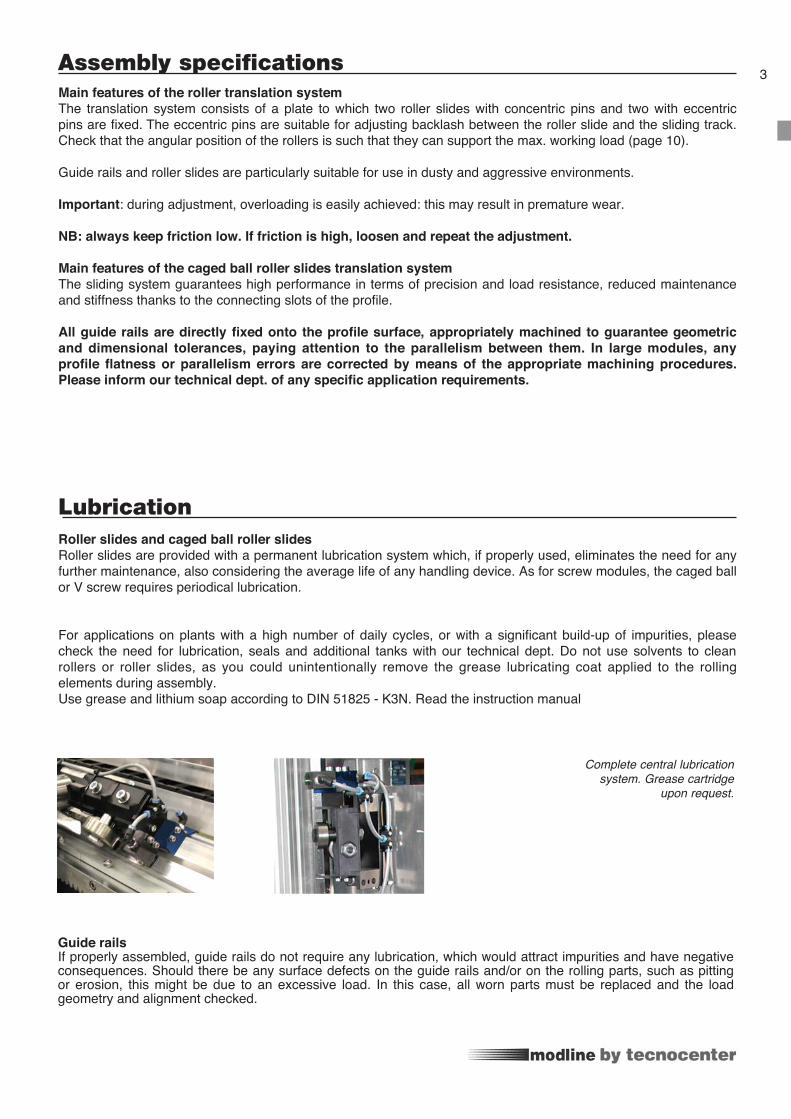
LubricationRoller slides and caged ball roller slidesRoller slides are provided with a permanent lubrication system which, if properly used, eliminates the need for any further maintenance, also considering the average life of any handling device. As for screw modules, the caged ball or V screw requires periodical lubrication.
For applications on plants with a high number of daily cycles, or with a significant build-up of impurities, please check the need for lubrication, seals and additional tanks with our technical dept. Do not use solvents to clean rollers or roller slides, as you could unintentionally remove the grease lubricating coat applied to the rolling elements during assembly.Use grease and lithium soap according to DIN 51825 - K3N. Read the instruction manual
Assembly specificationsMain features of the roller translation systemThe translation system consists of a plate to which two roller slides with concentric pins and two with eccentric pins are fixed. The eccentric pins are suitable for adjusting backlash between the roller slide and the sliding track. Check that the angular position of the rollers is such that they can support the max. working load (page 10).
Guide rails and roller slides are particularly suitable for use in dusty and aggressive environments.
Important: during adjustment, overloading is easily achieved: this may result in premature wear.
NB: always keep friction low. If friction is high, loosen and repeat the adjustment.
Main features of the caged ball roller slides translation systemThe sliding system guarantees high performance in terms of precision and load resistance, reduced maintenance and stiffness thanks to the connecting slots of the profile.
All guide rails are directly fixed onto the profile surface, appropriately machined to guarantee geometric and dimensional tolerances, paying attention to the parallelism between them. In large modules, any profile flatness or parallelism errors are corrected by means of the appropriate machining procedures. Please inform our technical dept. of any specific application requirements.
3
Guide railsIf properly assembled, guide rails do not require any lubrication, which would attract impurities and have negative consequences. Should there be any surface defects on the guide rails and/or on the rolling parts, such as pitting or erosion, this might be due to an excessive load. In this case, all worn parts must be replaced and the load geometry and alignment checked.
Complete central lubrication system. Grease cartridge
upon request.

4On request, we can supply systems complete with specific motor drives for industrial automation applications, suitable for specific handling tasks according to the customer’s needs (moving loads, accelerations, speeds, cycle times, resolution, repeatability).These can be equipped with gearboxes, servomotors, mechanical limit switches, proximity switches and various accessories, such as energy chains, interface plates, fixing supports.
Our technical dept. is at your complete disposal for any scaling requirements and the choice of moving unit and electromechanical parts suitable to achieve the required performance levels. We can draw on our experience to help our customers in their choice of linear unit and the following parts:gearboxes: worm screw, planetary, bevel; motors: stepper, brushless, DC, asynchronous.
For each of these we can propose drives manufactured by primary producers marketed in Italy and abroad suitable for the calculated power ratings.Tecno Center is able to support the customer in choosing complete systems equipped with axis control, with or without interpolation, with or without PLC, suitable for operating handling cycles and machine management. The customer has only to provide for piping and wiring.
Application examples:
glue releasing unitspaint or resin distribution unitsload/unload of manufacturing machinespick and place systems control and sensing instrument handlingdrilling boardscartesian robots with 2, 3 or more axes
Introduction - operation and control unit
Tightening specifications
During set-up, make sure all parts are locked with the appropriate screws and with the right tightening torques.

Standard assembly solutions
3 4
7
5
1
6
8
8
1 2
5

Sizing templateOur Technical Support dept. is available to check sizing calculations. Please fill in the form with all the necessary data and send it to our technical dept., which will suggest the most suitable size according to the forces applied and precision required.
6
Z-axis
X-axis
X-axis
Y-axis
Leftside
Leftside
Motor
Rightside
Rightside
Y-axis
TRANSVERS
HORIZONTAL
VERTICAL

Sizing request form
Date: ...................................................................Request N°:.......................
Filled in by:.....................................................................................................
Company: ........................................................................................................
Address:..........................................................................................................
Tel.: .....................................................Fax:.....................................................
E-mail:..............................................................................................................
Tecno Center C.so Lombardia, 41
10078 Venaria Reale (TO) ITALY
Tel.: +39-011 455 11 21 (R.A.)
Fax.: +39-011 455 75 95
e-mail: [email protected]
Web: www.tecno-center.it
For a proper definition of the linear units, fill in the scaling request form and send it to the Technical SupportDepartment.
Notes: ..............................................................................................................................................................................................
..........................................................................................................................................................................................................
..........................................................................................................................................................................................................
..........................................................................................................................................................................................................
7
Sizing template MODLINE linear modules
Working cycle Example working cycle
requireddata
optional data
ASSEMBLY SOLUTIONS (see page 5) n° Z-axis Y-axis X-axisTotal length of profile (excluding heads) Lz Ly Lx [mm]Total working load including gripper (add Z axis for Y and X axes) Pc Py Px [kg]Equipment weight on carriage (gearbox, cylinder, OPTIONAL) Paz Pay Pax [kg]Weight distributed on the beam (energy chain) Pdz Pdy Pdx [kg/m]Profile supports n° n°Max. projection (any overhang, the biggest) Sz Sy Sx [mm]Max. span Ldy Ldx [mm]Offset load’s centre of gravity (X-axis) Lcx [mm]Offset load’s centre of gravity (Y-axis) Lcy [mm]Offset load’s centre of gravity (Z-axis) Lcz [mm]Any additional force F [N]Offset additional force (X-axis) Lfx [mm]Offset additional force (Y-axis) Lfy [mm]Offset additional force (Z-axis) Lfz [mm]Possible distance between the carriages Dz Dy Dx [mm]Transmission performance η = Assembly: vertical= 90° - slope = 30°, 45°, 60° - horizontal α= Stroke Speed Vz Vy Vx [m/s]Acceleration Az Ay Ax [m/s2]Stroke time Tz Ty Tx [s]Positioning accuracy and repeatability +/- [mm]Work environment (temperature and cleanliness) Daily working cycles n°
Qz Qy Qx

Preliminary selection table (1-2-3 axes)These tables are useful for making a preliminary selection with load applied in a central position with respect to the plate or profile axis. Z axis length is < 1600 mm. Deflection is computed assuming continuous beams having the same span and concentrated static loads.
In the following table, select the appropriate X axes according to the load
From the table below, select the most suitable combination of Y-Z axes depending on the load.
From the table below, select the most suitable combination of X-Y-Z axes depending on the load.
NB : the choice of X axis is based upon the actual load, the supporting points, max. deflection and the total weight of the Y-Z axes
NB: for vertical 8X and 10X portals, compensate the load
X-Axis
Y-Z-Axis
X-Y-Z-AxisY-Z-axis
EXAMPLE: selection of 3-axis portal with roller slides(Please see page 7 and the portal pages for the nomenclature)
DATA: Total working load 300 kg, X axis stroke: 5,000 mm, Y axis stroke: 4,000 mm, Z axis stroke: 2,000 mm, support points: 2
By analysing the table of Y-Z axes based on the working load (Pc), profile length (Ly) and deflection, the selection falls on one PA 8/3 (load 300 kg.) portal Check: Peff = Pmax- (Lz - 1,600)/1,000•qz = 300-(2,900-1,600)/1,000•35 = 254.5 kg. < di 300 kg. Therefore select the larger size PA 6/4 (max. load capacity 400 kg.) Mtot PA 6/4 (Y+Z) = Mbase+(qy•strokey+qz• strokez)/1,000+Pc = 244+(66•4,000+48•2,000)/1,000+300 = 904 kg. Ptx = Mtot PA 6/4 (Y+Z)•0.66 = 596.6 kg. Lx = strokex + 1,200 approx = 5,000+1,200 = 6,200 mmBy analysing the table of X axes based on the load (Ptx) profile length (Lx) and deflection, it is possible to select two PA 6X linear axesChosen composition: n°1 PA 6/4 + n° 2 PA 6X
Perform a final analysis by computing the deflection based on the actual size of the spans. Our technical dept. is at your complete disposal to help you examine the most suitable applications for your requirements.
Max
. Loa
d ca
paci
ty [k
g.]
Max
. Loa
d ca
paci
ty [k
g.]
X-ax
is
Deflection PA 2X 3X 4X 5X 6X 8X 10X LC
50 1.4 5000100 1.8 5000200 2.7 1.8 5000300 2.3 2.7 5000400 3.3 2.4 5000500 2.8 1.8 5000600 2 2 6000800 2.5 1.8 60001000 2.1 7000
Deflection PA 2/1 3/1 4/1 5/2 6/2 8/3 6/4 8/6 10/6 10/8 LC
50 1.9 5000100 2.4 1.7 2 1.6 5000200 2.2 0.8 0.8 5000300 1.6 1.6 1.6 6000400 1.9 2 0.9 6000500 2.2 1 6000600 2.5 1.2 1.2 6000800 2.2 7000
PA 2/1 3/1 4/1 5/2 6/2 8/3 6/4 8/6 10/6 10/8PA Load [kg.] 100 100 100 200 200 300 400 600 600 7002X 3X 4X 5X 6X 8X10X
8

Special applications with standard modules9
1 2
3 4
5 6
7
Multi-gripper handling system with belt drive
Panel handling system, construction industry
Tool handling system in the iron and steel industry
Pick and place system for storage battery production plant
Pick and place system for packaging plant
Pick and place system for breadboards
Pick and place system for production plant
2
4
5
3
1
6
7

...
10 Assembly positions and load direction
KEY:
A C
D
E
F
B
Head motor side
Head Idle side
Direction of load
Linear axis support
For rollers profiles.
Simplified code setting of the moduleEXAMPLE T
HANDLING
PROFILE SIZE
STROKE / LENGHT
MACHINING PROFILE
ACCESSORY CODES
SERIES
K= lightM= compact closed sectionT= heavyZ= vertical omega belt
C= belt CE= large beltV= ball screw T= trapezoidal screwN= idleL= linear motor
SLIDE
RR / RQ /RP = guide rails for roller sl. Ø30 / Ø40 / Ø52 o Ø62S= guide rails for caged balls roller slidesH= guide rails for caged ball roller slidesG= guide rails for cylindrical shaped rollers Y= guide rails for polyamide shaped rollers
M= profile with machined guide plane and rack plane
“mm” = X-axis / Y-axis / Z-axis
Various accessory codes
C 280S M mm/mm/
X-axis
Z-axis
Y-axis
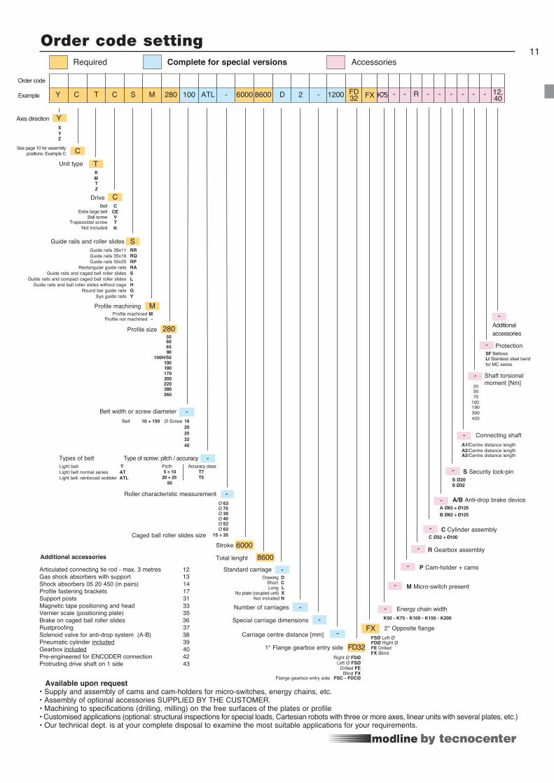
11Order code setting
Y T C M 280 100 ATL -S 6000 D 2 -8600
YAxis direction
TUnit type
Drive C
280Profile size
-Types of belt Type of screw: pitch / accuracy
SGuide rails and roller slides RR RQ RP RA S L H G Y
-Roller characteristic measurement
Ø 30
Ø 52
15 ÷ 35 Ø 62
Profile machiningProfile machined M
Profile not machined -
65 90
100H/50 100 180 170
200 220 280 360
6000Stroke
8600Total lenght
-Standard carriage
FD321200
--Special carriage dimensions
-Carriage centre distance [mm]
FD321° Flange gearbox entry sideRight Ø FDØ Left Ø FSØ
FX
Energy chain width
M Micro-switch present
P Cam-holder + cams
R Gearbox assembly
C Ø32 ÷ Ø100 C Cylinder assembly
A/B Anti-drop brake device
S Security lock-pin
Connecting shaft A1/Centre distance lengthA2/Centre distance lengthA3/Centre distance length
20 35
100 190 300
70
420
Shaft torsional moment [Nm]
-
Ø 40
Ø 63 Ø 75
M
Not included N
Drawing D
-
-
-
-
-
-
-
-
-
- Protection SF Bellows
12,40
-Additional accessories
Articulated connecting tie rod - max. 3 metres 12Gas shock absorbers with support 13Shock absorbers 05 20 450 (in pairs) 14Profile fastening brackets 17 Support posts 31Magnetic tape positioning and head 33Vernier scale (positioning plate) 35Brake on caged ball roller slides 36Rustproofing 37Solenoid valve for anti-drop system (A-B) 38Pneumatic cylinder included 39Gearbox included 40Pre-engineered for ENCODER connection 42Protruding drive shaft on 1 side 43
Additional accessories
Order code
Example
Belt width or screw diameter
Complete for special versionsRequired Accessories
K75 - - R - - - - - -
No plate (coupled unit) X
Drilled FE
A Ø63 ÷ Ø125
Caged ball roller slides size
B Ø63 ÷ Ø125
X Y Z
K50 - K75 - K100 - K150 - K200
K M T Z
C CE V T
Belt
Ball screw
Belt 10 ÷ 150 Ø Screw 16 20 25 32 40
Light belt T Light belt normal series AT Light belt: reinforced wobbler ATL
Short CLong L
LI Stainless steel band for MC series
Blind FXFlange gearbox entry side FSC - FDCØ
Extra large belt
Trapezoidal screw NNot included
60 50
FX
2° Opposite flange FSØ Left ØFDØ Right ØFE DrilledFX Blind
Guide rails 28x11Guide rails 35x16
Guide rails 55x25 Rectangular guide rails Guide rails and caged ball roller slides
Guide rails and compact caged ball roller slides Guide rails and ball roller slides without cage
Round bar guide railsSys guide rails
Available upon request• Supply and assembly of cams and cam-holders for micro-switches, energy chains, etc.• Assembly of optional accessories SUPPLIED BY THE CUSTOMER.• Machining to specifications (drilling, milling) on the free surfaces of the plates or profile• Customised applications (optional: structural inspections for special loads, Cartesian robots with three or more axes, linear units with several plates, etc.) • Our technical dept. is at your complete disposal to examine the most suitable applications for your requirements.
5 ÷ 10 20 ÷ 25
50
T7 T5
Picth Accuracy class
S Ø20S Ø32
C
C
See page 10 for assembly positions. Example C
Number of carriages

14,6 8
11
2380
4
8058
X
Y
X
Y
11
14,6 8
4 70105
28
105
Y
X
4
13,5
Ø 6,8 5,5
5,5
Ø 14
60
60
22 8
Profile M 80x80
Weight per metre approx. 6.3 [kg/m]
Max. length 6 [m]
Moment of inertia IY 1,430,000 [mm4]
Moment of inertia IX 1,780,000 [mm4]
Module MCR/S/H 80 - MVR/S/T 80
Profile M 105x105
Weight per metre approx. 11 [kg/m]
Max. length 10.45 [m]
Moment of inertia IY 4,466,000 [mm4]
Moment of inertia IX 5,660,000 [mm4]
Module MCR/S/H - MVR/S/T 105
Profile (60x60) F01-1
Weight per metre approx 3.6 [kg/m]
Max. length 6 [m]
Moment of inertia IY 466,600 [mm4]
Moment of inertia IX 466,600 [mm4]
Module ZCG/L 60
Profile specifications
67
65
50
18
8
12,2
2,7
8,7
X
Y
Profile M 65x67
Weight per metre approx. 4.5 [kg/m]
Max. length 9 [m]
Moment of inertia IY 683,900 [mm4]
Moment of inertia IX 796,750 [mm4]
Module MCR/L/H 65
X
Y
9079
82
Ø 14
4525,4
12,7
3,7
23
9
Ø6,8
Profile (90x90) E01-4
Weight per metre approx. 6 [kg/m]
Max. length 6 [m]
Moment of inertia IY 2,027,000 [mm4]
Moment of inertia IX 2,027,000 [mm4]
Module ZCG - ZCL - ZCRR 90
12

Profile (50x100) MA 1-2 MA 1-4
Weight per metre approx. 5.3 5.2 [kg/m]
Max. length 6 6 [m]
Moment of inertia IY 502,800 543,100 [mm4]
Moment of inertia IX 1,986,600 2,036,700 [mm4]
Module ZCR/L 100H TCG/TCS/H 100
180
13545
9045
Y
X
8,2
22
3,8 5,5 5,5
Ø 6,9
Ø 14
12,7
Profile (100x100) MA 1-5
Weight per metre approx. 9.5 [kg/m]
Max. length 6 [m]
Moment of inertia IY 3,650,000 [mm4]
Moment of inertia IX 3,800,000 [mm4]
Module ZCR/L 100
Profile (90x180) E01-5
Weight per metre approx. 12.4 [kg/m]
Max. length 8 [m]
Moment of inertia IY 4,420,000 [mm4]
Moment of inertia IX 15,180,000 [mm4]
Module TCR/G/S/H/ 180
148,5
4
100
21 8
50 100
X
Y
50
7,5 7,5
Ø 13,7
Ø 6,8
100
50 7,5
7,5
48,
5
14
8
22
50
Ø 1
3,7
Ø 6,8 X
Y
13
50
25100
25 25 25
Y
X
Ø 13,7
84
44
29
Ø 6,822
7400568 energy chain support profile
Weight 1.5 kg/mAvailable lenght 6 m
105
64,5
51,5
8
1460
4

170
100
120
X
50
Y
21 12,5
21
6 12,25
12,2
5
ø 17,5
ø 14 Statyca (120x170) Code 202.1753
Weight per metre approx. 17 [kg/m]
Max. length 6 [m]
Moment of inertia IY 10,200,000 [mm4]
Moment of inertia IX 20,360,000 [mm4]
Module TCR/S/H 170 - ZCR/L 170
50
150
220
17
120Y
50
X
21
6
21 12,5
12,5
20,5
12,25
12,2
5
Ø 17,5
Ø 14
6
200
100
X
120
50
Y
20,5
12,5
217
ø 17,5
Valyda (120x200) Code 202.1146
Weight per metre approx. 21 [kg/m]
Max. length 12 [m]
Moment of inertia IY 12,900,000 [mm4]
Moment of inertia IX 32,900,000 [mm4]
Module TCR/S/H 200
Anodised up to 9 [m]
Logyca (120x220) Code 202.2184
Weight per metre approx. 25 [kg/m]
Max. lenght 12 [m]
Moment of inertia IY 15,650,000 [mm4]
Moment of inertia IX 46,550,000 [mm4]
Module TCR/S/H 220-ZCR/L/ 220
Anodizzato fino a lungh. 9 [m]
14

180
100
Y
X
6052
50
20
16
90°
8
Rif. 129
4
Ø 14
3
23
8
17
2
8
SYS 1-G Code 302.0001
Weight per metre approx. 12 [kg/m]
Max. lenght 7.5 [m]
Moment of inertia IY 1,600,000 [mm4]
Moment of inertia IX 12,350,000 [mm4]
Module ZCY180
*Holes for M16 thread and for PVS connecting elements
190
280
109 17
0
X
Y
18
12,5
20,5
7
19240
Pratyca (170x280) Code 202.1147
Weight per metre approx. 40 [kg/m]
Max. length 12 [m]
Moment of inertia IY 50,288,000 [mm4]
Moment of inertia IX 134,103,000 [mm4]
Module TCR/RP/S/H 280
Usually not anodised
®
15
Solyda (200x360) Code 202.0342
Weight per metre approx. 60 [kg/m]
Max. length 12 [m]
Moment of inertia IY 318,687,000 [mm4]
Moment of inertia IX 105,533,000 [mm4]
Module TCRP/S/H 360
Usually not anodised
X
200
270
200
8257
320
360
y
712,5 20,5

65
59
79
M6
13
3,3
30,8
5
61,7
9
36,5
M5
6520
67
10 150 1087 86
6015 60 15
16
The dynamic values shown do not refer to the max. theoretical load capacity. They include a safety coefficient for automated machinery. In case of peak forces acting together please ask the technical dept
Constructive data
To calculate the module weight use the following formula: M=Mbase+q•strokemax/1,000 (strokemax in mm)
Belt 32AT05Slide Rollers: 4 Ø 24 - 4 Ø 22 [mm]Load bearing profile 65x67 (see page 12)Pulley Ø 50.93 [mm]Linear displacement per revolution 160 [mm]
Suggested working load conditionsModule Mx[Nm] My[Nm] Mz[Nm] Fx[N] Fy[N] Fz[N]
Weights
Inertia of the pulley - [kgm2]Belt weight 0.22 [kg/m]Carriage weight 1 [kg]Base module (stroke=0) Mbase=4.4 [kg]1,000 mm profile q=5.4 [kg]
Series M Modules with belt drive
Performances MCR 65
Max. stroke 5,830 [mm]Max. speed 4 [m/s]Max. acceleration 20 [m/s2]Repositioning accuracy ± 0,1 [mm]Loadless torque - [Nm]
MCR 65 45 94 34 1,180 670 1,000
Total lenght = 343 + Max. StrokeMax. Stroke
59
79
MCR 65Option: lighter version with pulley seats integrated within the profile
Accessories: see page 11
HARDENED GUIDE RAILS AND SHAPED ROLLERS
Registered model
Ø(SEE PAGE 56-57)
Fx= Max belt strength
Mz
Fx
Mx
Fz
MyFy
SCREWS FOR BELT TENSION

Attenzione
celettatore?
M6
13
3,3
30,8
5
61,7
9
36,5
M6
6520
67
10 150 1087 86
6015 60 15
65
59
79
49
17MCS 65 - MCH 65
Constructive data
Belt 32AT05Slide 2 caged balls roller slides15 [mm]Load bearing profile 65x67 (see page 12)Pulley Ø 50.93 [mm]Linear displacement per revolution 160 [mm]
Weights
Performances MCS 65 MCH 65
Max. stroke 7,830 7,830 [mm]Max. speed 5 3 [m/s]Max. acceleration 50 30 [m/s2]Repositioning accuracy ± 0.1 ± 0.1 [mm]Loadless torque - - [Nm]
Total lenght = 343 + Max. Stroke
Inertia of the pulley - [kgm2]Belt weight 0.22 [kg/m]Carriage weight 1,1 [kg]Base module (stroke=0) Mbase=4.2 [kg]1,000 mm profile q=6.2 [kg]
Max. Stroke
Option: lighter version with pulley seats integrated within the profileAccessories: see page 11
GUIDE RAILS AND CAGED BALL ROLLER SLIDES
Registered model
Ø(SEE PAGE 56-57)
Fx= Max belt strength
Mz
Fx
Mx
Fz
MyFy
SCREWS FOR BELT TENSION
MCH 65 19 120 120 1,180 1,960 1,960 1,960 MCS 65 16 140 103 1,180 2,094 3,740 2,320
Suggested working load conditions
Module Mx[Nm] My[Nm] Mz[Nm] Fx[N] Fy[N] Fz[N] FzB[N]
To calculate the module weight use the following formula: M=Mbase+q•strokemax/1,000 (strokemax in mm)
The dynamic values shown do not refer to the max. theoretical load capacity. They include a safety coefficient for automated machinery. In case of peak forces acting together please ask the technical dept

Option: version with additional belt protection (see page 66)Option: short carriage version - code C
78
100
80
18,5
9,3M6 20
40
50
80
80
129
10M6
11 11 114
50
25
50
25
25
25
60
130
50
25
25
Mz
Fx
Mx
Fz
MyFy
Constructive data
Belt 32AT10Slide Rollers: 4 Ø 24 - 4 Ø 22 [mm]Load bearing profile 80x80 (see page 12)Pulley Ø 70.03 [mm]Linear displacement per revolution 220 [mm]
Weights
Inertia of the pulley 0.0010 [kgm2]Belt weight 0.38 [kg/m]Carriage weight 2 [kg]Base module (stroke=0) Mbase=8 [kg]1,000 mm profile q=7 [kg]
MCR 80Registered model
Suggested working load conditionsModule Mx[Nm] My[Nm] Mz[Nm] Fx[N] Fy[N] Fz[N] MCR 80 51 200 80 2,150 850 1,400
Total lenght = 343 + Max. Stroke (short carriage =415 + Max. Stroke)Max. Stroke
Ø(SEE PAGE 56-57)
18
130 (short carriage: 65)
280 (short carriage option: 150)
short carriage option
Suggested working load conditions short carriage optionModule Mx[Nm] My[Nm] Mz[Nm] Fx[N] Fy[N] Fz[N] MCR 80...C 51 100 40 2,150 850 1,400
Accessories: see page 11
Fx= Max belt strength
Mz
Fx
Mx
Fz
MyFy
SCREWS FOR BELT TENSION
HARDENED GUIDE RAILS AND SHAPED ROLLERS
To calculate the module weight use the following formula: M=Mbase+q•strokemax/1,000 (strokemax in mm)
The dynamic values shown do not refer to the max. theoretical load capacity. They include a safety coefficient for automated machinery. In case of peak forces acting together please ask the technical dept
Performances MCR 80
Max. stroke 5,700 [mm]Max. speed 5 [m/s]Max. acceleration 20 [m/s2]Repositioning accuracy ± 0.1 [mm]Loadless torque 0.7 [Nm]

80
78
100
505025 130 25
252525 50 25
129
10
M6
11 11 114
80 60
18,5
9,3M6 20
40
50
80
Constructive data MCS80 - MCH80
Belt 32AT10 Slide 2 caged ball roller slides size 15*Load bearing profile 80x80 (see page 12)Pulley Ø 70.03 [mm]Linear displacement per revolution 220 [mm]* Short carriage option 1 pad
Weights MCS80 - MCH80
Inertia of the pulley 0.0010 [kgm2]Belt weight 0.38 [kg/m]Carriage weight 2.6 [kg] Base module (stroke=0) Mbase=9 [kg]1,000 mm profile q=8.2 [kg]
MCS 80 e MCH 80
Total lenght = 545 + Max. Stroke (short carriage = 415 + Max. Stroke)Max. Stroke 280 (short carriage option: 150)
130 (short carriage: 65)
short carriage option
Ø(SEE PAGE 56-57)
Registered model
Performances MCS 80 MCH 80 Max. stroke 5,700 5,700 [mm]Max. speed 5 5 [m/s]Max. acceleration 40 40 [m/s2]Repositioning accuracy ± 0,1 ± 0,1 [mm]Loadless torque 0.9 0.9 [Nm]
19 GUIDE RAILS AND CAGED BALL ROLLER SLIDES
Option: version with additional belt protection (see page 66)Option: short carriage version - code C
Accessories: see page 11
Fx= Max belt strength
Mz
Fx
Mx
Fz
MyFy
SCREWS FOR BELT TENSION
Suggested working load conditions
MCS 80 52 400 400 2,150 4,200 4,200MCH 80 30 290 290 2,150 2,900 2,900
Module Mx[Nm] My[Nm] Mz[Nm] Fx[N] Fy[N] Fz[N]
Suggested working load conditions
MCS 80...C 16.5 15 15 2,150 2,100 2,100MCH 80...C 14 15 12 2,150 1,450 1,450
Module Mx[Nm] My[Nm] Mz[Nm] Fx[N] Fy[N] Fz[N]
To calculate the module weight use the following formula: M=Mbase+q•strokemax/1,000 (strokemax in mm)
The dynamic values shown do not refer to the max. theoretical load capacity. They include a safety coefficient for automated machinery. In case of peak forces acting together please ask the technical dept

70
130
99
24,3 5 20
52,5
63
105,
9
17,5 137145M6
17,5
105
6,5
105
15,5
12
8
Mz
FxMx
Fz
MyFy
HARDENED GUIDE RAILS AND SHAPED ROLLERS
Constructive data
Belt 40AT10 Slide Rollers: 4 Ø 37 - 4 Ø 35 [mm]Load bearing profile 105x105 (see page 12)Pulley Ø 92.31 [mm]Linear displacement per revolution 290 [mm]
Weights
Inertia of the pulley 0.0037 [kgm2]Belt weight 0.47 [kg/m]Carriage weight 3.5 [kg]Base module (stroke=0) Mbase=16.5 [kg]1,000 mm profile q=13 [kg]
MCR 105Option: version with additional belt protection (see page 66)
*Option: short carriage version - (code C) or long carriage (code L)
Prestazioni MCR 105
Max. stroke 10,100 [mm]Max. speed 5 [m/s] Max. acceleration 20 [m/s2]Repositioning accuracy ± 0.1 [mm]Loadless torque 1.2 [Nm]
Registered model
Total lenght = 615 + Max. Stroke (short carriage = 515 + Max. Stroke)Max. Stroke
Ø(SEE PAGE 56-57)
20
140 (short carriage :90)290 (long carriage )
300 (short carriage option: 200)
Performances MCR 105
Suggested working load conditions
MCR 105 185 580 220 3,300 1,500 2,950Module Mx[Nm] My[Nm] Mz[Nm] Fx[N] Fy[N] Fz[N]
Suggested working load conditions short carriage option
MCR 105...C 185 330 130 3,300 1,450 2,950Module Mx[Nm] My[Nm] Mz[Nm] Fx[N] Fy[N] Fz[N]
Accessories: see page 11
Fx= Max belt strength
Mz
Fx
Mx
Fz
MyFy
4 M6 INSERTS FOR EACH SIDE THAT CAN BE ADJUSTED IN THE SLOT
SCREWS FOR BELT TENSION
To calculate the module weight use the following formula: M=Mbase+q•strokemax/1,000 (strokemax in mm)
The dynamic values shown do not refer to the max. theoretical load capacity. They include a safety coefficient for automated machinery. In case of peak forces acting together please ask the technical dept

GUIDE RAILS AND CAGED BALL ROLLER SLIDES
130
99
63
52,5
105,
9
20
24,3 5
105
70
17,5 137145 17,5M6
6,5
105
12
15,5 8
Constuctive data
Belt 40AT10 Slide 2 caged ball roller slides size 20*Load bearing profile 105x105 (see page 12)Pulley Ø 92.31 [mm]Linear displacement per revolution 290 [mm]* Short carriage option 1 pad
Weights
Inertia of the pulley 0.0037 [kgm2]Belt weight 0.47 [kg/m]Carriage weight 4.5 [kg]Base module (stroke=0) Mbase=18 [kg]1,000 mm profile q=14.3 [kg]
MCS 105 e MCH 105
Performances MCS 105 MCH 105 Max. stroke 10,100 10,100 [mm]Max. speed 5 5 [m/s]Max. acceleration 50 50 [m/s2]Repositioning accuracy ± 0.1 ± 0.1 [mm]Loadless torque 1.5 1.5 [Nm]
Option: version with additional belt protection (see page 66)*Option: short carriage version - (code C)
Registered model
Total lenght = 615 + Max. Stroke (short carriage = 515 + Max. Stroke)Max. Stroke 300 (short carriage option: 200)
140 (short carriage:90)
Ø(SEE PAGE 56-57)
21
Accessories: see page 11
Fx= Max belt strength
Mz
Fx
Mx
Fz
MyFy
4 M6 INSERTS FOR EACH SIDE THAT CAN BE ADJUSTED IN THE SLOT
SCREWS FOR BELT TENSION
Suggested working load conditions
MCS 105 156 800 800 3,300 9,550 9,550MCH 105 116 600 600 3,300 6,030 6,030
Module Mx[Nm] My[Nm] Mz[Nm] Fx[N] Fy[N] Fz[N]
Suggested working load conditions short carriage option
MCS 105...C 51 52 52 3,300 4,777 4,777MCH 105...C 36 30 30 3,300 3,018 3,018
Module Mx[Nm] My[Nm] Mz[Nm] Fx[N] Fy[N] Fz[N]
To calculate the module weight use the following formula: M=Mbase+q•strokemax/1,000 (strokemax in mm)
The dynamic values shown do not refer to the max. theoretical load capacity. They include a safety coefficient for automated machinery. In case of peak forces acting together please ask the technical dept

105
17,5 13717,5300 M6 6,
5
145
70
52,5
105,
9
63
24,3 20 1405
130
9910
5
12
15,5 8
MCHH 105 TWIN GUIDE RAIL AND CAGED BALL ROLLER SLIDES
Total lenght =615 + Max. Stroke
Max. Stroke
22
Constructive data
Belt 40ATL10 Slide 4 caged ball roller slides size 15Load bearing profile 105x105 (see page 12)Pulley Ø 92.31 [mm]Linear displacement per revolution 290 [mm]
Weights
Inertia of the pulley 0.0037 [kgm2]Belt weight 0.47 [kg/m]Carriage weight 4.5 [kg]Base module (stroke=0) Mbase=18 [kg]1,000 mm di profile q=14 [kg]
Ø(SEE PAGE 56-57)
Registered model Accessories: see page 11
Suggested working load conditions
MCHH 105 210 1.033 700 3,300 7,200 6,210 Module Mx[Nm] My[Nm] Mz[Nm] Fx[N] Fy[N] Fz[N]
Fx= Max belt strength
Mz
Fx
Mx
Fz
MyFy
4 M6 INSERTS FOR EACH SIDE THAT CAN BE ADJUSTED IN THE SLOT
SCREWS FOR BELT TENSION
To calculate the module weight use the following formula: M=Mbase+q•strokemax/1,000 (strokemax in mm)
The dynamic values shown do not refer to the max. theoretical load capacity. They include a safety coefficient for automated machinery. In case of peak forces acting together please ask the technical dept
Prestazioni MCR 105
Max. stroke 7,400 [mm]Max. speed 5 [m/s] Max. acceleration 50 [m/s2]Repositioning accuracy ± 0.1 [mm]Loadless torque 2.2 [Nm]
Performances MCHH 105

Max. acceleration 5 2 [m/s2]Repositioning accuracy ± 0,05 ± 0,20 [mm]
The values shown refer to maximum performance with each force acting individual-ly. The dynamic data shown do not refer to the max. theoretical load capacity. They include a safety coefficient for automated machinery. (*) With a pitch of 5 mm
Constructive data
Suggested working load conditionsModule Mx[Nm] My[Nm] Mz[Nm] Fx[N] Fy[N] Fz[N]
Weights
MVR 80 51 200 80 *1,600 850 1,400MTR 80 51 200 80 *2,000 850 1,400
Modules with screw drive
MVR 80 - MTR 80HARDENED GUIDES
WITH CYLINDRICAL SHAPED ROLLERS - TRAPEZOIDAL BALL SCREW
Ø73
120°
M5
16
213
24
1611
3
15
37
280
4
13
100
80
11
Ø 5
9 h7
Ø 1
0 h8
11,
2
[mm][mm]
N/D5-10
SI
Max. StrokeModule total lenght
Type of carriageScrew pitch
Pedestal bearings
V = Ball screwT = Trapezoidal screw
R = Rollers
M T RCode
Max. stroke-speed limit over which some pedestal bearingsare required (SI) to avoid an excessive screw oscillation. The working point marked insidethe broken line is not recommended.
n [r
pm]
015
00
Lunghezza [mm]
senza SI
3000
Performances MVR 80 MTR 80
Max. stroke 2,500 3,000 [mm]
Max. speedPitch 5 0.15 Pitch 4 0.10 [m/s] Pitch 10 0.30 Pitch 8 0.20 [m/s]Pitch 16 0.50 [m/s]
Total lenght =376 + Max. StrokeTotal lenght = 302 + Max. Stroke
Screw lenght = Stroke + 372
Max. Stroke
23
Slide Rollers: 4 Ø24 - 4 Ø22 [mm]Beam 80x80 (see page 12)Ø screw 16 [mm]Lenght of the screw 367+maxstroke [mm]
Inertia of the worm 0.0003 • L. screw(m) [kgm2]Carriage weight 2.5 c.a. [kg]Base module (stroke=0) Mbase= 5.5 approx. [kg]1,000 mm profile q=8 approx. [kg]
Fx= Max belt strength
Mz
Fx
Mx
Fz
MyFy
To calculate the module weight use the following formula: M=Mbase+q•strokemax/1,000 (strokemax in mm)
Lenght [mm]

Mz
Fx
Mx
Fz
MyFy
30063
36
30 17,5 2217,5
M66,5
105
70
5
Ø80
h7
815
,5
12,5
105
135205
17
640
18Ø16
h863
99
45°M6Ø95
130
80°
The values shown refer to maximum performance with each force acting individually. The dynamic data shown do not refer to the max. theoretical load capacity. They include a safety coefficient for automated machinery. (*) With a pitch of 5 mm
Max. stroke-speed limit over which some pedestal bearingsare required (SI) to avoid an excessive screw oscillation. The working point marked insidethe broken line is not recommended.
Constructive dataSlide Rollers: 4 Ø 37 - 4 Ø 35 [mm]Beam 105x105 (see page 12)Ø screw 25 [mm]Lenght of the screw 440+maxstroke [mm]
Weights
Inertia of the worm 0.0003 • L. screw(m) [kgm2]Carriage weight 4 approx. [kg] Base module (stroke=0) Mbase=11 [kg]1,000 mm profile q=17.2 approx. [kg]
MVR 105 e MTR 105HARDENED GUIDES
WITH CYLINDRICAL SHAPED ROLLERS - TRAPEZOIDAL BALL SCREW
Performances MVR 105 MTR 105
Max. stroke Pitch 5 -10 = 4550 Pitch 25 = 5,150 [mm]
Max. speedPitch 5 [mm] 0.15 0.075 [m/s] Pitch 10 [mm] 0.30 0.15 [m/s]Pitch 25 [mm] 0.75 0.37 [m/s]
Max. acceleration 5 2 [m/s2]Repositioning accuracy ± 0.05 ± 0.2 [mm]
Registered model
Total lenght = 450 + Max. Stroke
Max. Stroke
[mm][mm]
N/D5-10-25-50
SI
Max. strokeModule total lenght
Type of carriageScrew pitch
Pedestal bearings
V = Ball screwT = Trapezoidal screw
R = Rollers
M T RCode ball screw
24
n [r
pm]
Lunghezza [mm]
0
500225125 80
2000
8000
Fx= Max belt strength
Mz
Fx
Mx
Fz
MyFy
4 M6 INSERTS FOR EACH SIDE THAT CAN BE ADJUSTED IN THE SLOT
Suggested working load conditions
MVR 105 185 580 220 *2,000 1,500 2,950MTR 105 185 580 220 *3,000 1,500 2,950
Module Mx[Nm] My[Nm] Mz[Nm] Fx[N] Fy[N] Fz[N]
To calculate the module weight use the following formula: M=Mbase+q•strokemax/1,000 (strokemax in mm)
Lenght [mm]

30063
36
30 15 22
M6
15
5
Ø80
h7
70
6,5
105
12,5
815
,5
99
105
Ø95 M6
130
80°
17
640
18Ø16
h863
135205
45°
Mz
Fx
Mx
Fz
MyFy
Max. stroke Pitch 5 -10 = 4,550 Pitch 25 = 5,150 [mm]
Constructive dataSlide 2 caged ball roller slides size 20Beam 105x105 (see page 12)Ø screw 25 [mm]Lenght of the screw 440+maxstroke [mm]
Suggested working load conditions
WeightsInertia of the worm 0.0003 • L. screw(m) [kgm2]Carriage weight 4 approx. [kg]Base module (stroke=0) Mbase=12 [kg]1,000 mm profile q=17.2 approx. [kg]
MVS 105 e MVH 105 GUIDE RAILS AND CAGED BALL ROLLER SLIDES - BALL SCREW
MVS 105 156 800 800 3,000(*) 9,550 9,550MVH 105 116 600 600 3,000(*) 6,030 6,030
25
Performances MVS 105 MVH 105
Max. speed
Total lenght = 445 + Max. Stroke
Max. Stroke
Max. stroke-speed limit over which some pedestal bearingsare required (SI) to avoid an excessive screw oscillation. The working point marked insidethe broken line is not recommended.
[mm][mm]
N/D5-10-25-50
SI
Max. strokeModule total lenght
Type of carriageScrew pitch
Pedestal bearings
V = Ball screwS = Caged ball roller slidesH = Ball roller slides
M V LCode ball screw
Module Mx[Nm] My[Nm] Mz[Nm] Fx[N] Fy[N] Fz[N]
The values shown refer to maximum performance with each force acting individually. The dynamic data shown do not refer to the max. theoretical load capacity. They include a safety coefficient for automated machinery. (*) With a pitch of 5 mm
Pitch 5 [mm] 0.15 0.15 [m/s] Pitch 10 [mm] 0.30 0.30 [m/s]Pitch 25 [mm] 0.75 0.75 [m/s]
Max. acceleration 5 5 [m/s2]Repositioning accuracy ± 0.05 ± 0.05 [mm]
n [r
pm]
Lunghezza [mm]
0
500225125 80
2000
8000
Fx= Max belt strength
Mz
Fx
Mx
Fz
MyFy
4 M6 INSERTS FOR EACH SIDE THAT CAN BE ADJUSTED IN THE SLOT
To calculate the module weight use the following formula: M=Mbase+q•strokemax/1,000 (strokemax in mm)
Lenght [mm]

Mz
FxMx
Fz
MyFy
30063
36
30 17,5 2217,5
M66,5
105
70
5
Ø80
h7
815
,5
12,5
105
135205
17
640
18Ø16
h863
99
45°M6Ø95
130
80°
The values shown refer to maximum performance with each force acting individually. The dynamic data shown do not refer to the max. theoretical load capacity. They include a safety coefficient for automated machinery. (*) With a pitch of 5 mm
Max. stroke-speed limit over which some pedestal bearingsare required (SI) to avoid an excessive screw oscillation. The working point marked insidethe broken line is not recommended.
MVHH 105 GUIDE RAILS AND CAGED BALL ROLLER SLIDES - BALL SCREW
Performances MVHH 105
Max Stroke Pitch 5 -10 = 4550 Pitch 25 = 5150 [mm]
Max SpeedPitch 5 [mm] 0,15 [m/s] Pitch 10 [mm] 0,30 [m/s]Pitch 25 [mm] 0,75 [m/s]
Max acceleration 5 [m/s2]Repositioning accuracy ± 0,05 [mm]
Registered model
TOTAL LENGHT = 450 + Max Stroke
Max STROKE
ball screw
26
n [r
pm]
Lunghezza [mm]
0
500225125 80
2000
8000
Fx= Max belt strength
Mz
Fx
Mx
Fz
MyFy
4 M6 INSERTS FOR EACH SIDE THAT CAN BE ADJUSTED IN THE SLOT
Suggested working load conditions
MVHH 105 185 500 500 *3.000 6.000 6.000Module Mx[Nm] My[Nm] Mz[Nm] Fx[N] Fy[N] Fz[N]
[mm][mm]
N/D 5-10-25
SI
Max StrokeModule total lenght
Type of carriageScrew pitch
Pedestal bearings
V=ball screwH=ball roller slides
M V HHCode
Constructive dataSlide 4 caged ball roller slides size 15Beam 105x105 (see page 12)Ø screw 25 [mm]Lenght of the screw 440+strokemax [mm]
WeightsInertia of the worm 0,0003 • L. screw(m) [kgm2]Carriage weight 4 c.a. [kg]Base module (stroke=0) Mbase=13 [kg]1,000 mm profile q=17,5 approx. [kg]
Lenght [mm]
To calculate the module weight use the following formula: M=Mbase+q•strokemax/1,000 (strokemax in mm)

Ø16
h8
Ø80
h718
5
38,5
52,5
7,6
137,
520
0
63
63
17 320 23
200
209013
7,5
135
77,8
60,8 27
,2 M6
Slide 4 caged ball roller slides size 20Beam E01-5 (see page 13)Ø screw 25 [mm]Bellow heat-sealed, plastic
27TVH 180 GUIDE RAILS AND CAGED BALL ROLLER SLIDES - BALL SCREW
TOTAL LENGHT = 436 + 2x(Stroke/9) + Stroke
Stroke / 9 * Stroke / 9 *
Constructive data
Suggested working load conditions
Weights
Inertia of the worm 0,0003 • L. screw(m) [kgm2]Carriage weight 7 [kg]Base module (stroke=0) Mbase= 20 [kg]1,000 mm profile q= 20 [kg]
TVH 180 600 850 850 *3.000 9.200 9.200 Module Mx[Nm] My[Nm] Mz[Nm] Fx[N] Fy[N] Fz[N]
The values shown refer to maximum performance with each force acting individually. The dynamic data shown do not refer to the max. theoretical load capacity. They include a safety coefficient for automated machinery. (*) With a pitch of 5 mm
*valore indicativo
Max. stroke-speed limit over which some pedestal bearings are required (SI) to avoid an excessive screw oscillation. The working point marked insidethe broken line is not recommended.
Fx= Max belt strength
Mz
Fx
Mx
Fz
MyFy
ball screw
n [r
pm]
Lunghezza [mm]
0
500225125 80
2000
8000
Max Stroke Pitch 5 -10 = 4550 Pitch 25 = 5150 [mm] Performances TVH 180
Max SpeedPitch 5 [mm] 0,15 [m/s] Pitch 10 [mm] 0,30 [m/s]Pitch 25 [mm] 0,75 [m/s]
Lenght [mm]
To calculate the module weight use the following formula: M=Mbase+q•strokemax/1,000 (strokemax in mm)

TVS 170 GUIDE RAILS AND CAGED BALL ROLLER SLIDES - BALL SCREWØ
22 h
8
24,5
42 7
M885
85
70
220
85
20
166
170
120
100
166
12.5
21
6
15
Ø10
0 h7
6
74 18
480
23
15 150 150 150
190
Total Lenght = 595 + 2x(Stroke/9) + Stroke
Stroke / 9 * Stroke / 9 *
Max. stroke 4,000 [mm]
Constructive data
Slide 4 caged ball roller slides size 20Beam Statyca (see page 14)Ø screw 32 [mm]Bellow heat-sealed, plastic
Suggested working load conditions
Weights
Inertia of the worm 0,0006 • L. screw(m) [kgm2]Carriage weight 11 [kg]Base module (stroke=0) Mbase= 36 [kg]1,000 mm profile q= 28 [kg]
TVS 170 720 2,050 2,050 *6,000 11,950 11,950
Performances TVS 170
Max. speed
Module Mx[Nm] My[Nm] Mz[Nm] Fx[N] Fy[N] Fz[N]
The dynamic values shown do not refer to the max. theoretical load capacity. They include a safety coefficient for automated machinery. In case of peak forces acting together please ask the technical dept. (*) With a pitch of 10 mm
Pitch 5 [mm] 0.15 [m/s] Pitch 10 [mm] 0.30 [m/s]Pitch 20 [mm] 0.75 [m/s]Pitch 32 [mm] 1.00 [m/s]
n [r
pm]
Lunghezza [mm]
0
650290162100
2600
10000
*approx. value
28
Max. stroke-speed limit over which some pedestal bearings are required (SI) to avoid an excessive screw oscillation. The working point marked insidethe broken line is not recommended.
Fx= Max belt strength
Mz
Fx
Mx
Fz
MyFy
To calculate the module weight use the following formula: M=Mbase+q•strokemax/1,000 (strokemax in mm)
Lenght [mm]

TVS 220 GUIDE RAILS AND CAGED BALL ROLLER SLIDES - BALL SCREW
85
7085 M8
101
12.5
21 6
15
150
270
220
120
20
172
6Ø10
0 h7
74 18480
23
15 150 150 150
240
42 7
17224
,5
Ø22
h8
Total lenght = 595 + 2x(Stroke/9) + Stroke
Stroke / 9 * Stroke / 9 *
Max. stroke-speed limit over which some pedestal bearings are required (SI) to avoid an excessive screw oscillation. The working point marked insidethe broken line is not recommended.
Constructive dataSlide 4 caged ball roller slides size 25Beam Logyca (see page 14)Ø screw 32 [mm]Bellow heat-sealed, plastic
Suggested working load conditions
WeightsInertia of the worm 0.0006 • L. screw(m) [kgm2]Carriage weight 13 [kg]Base module (stroke=0) Mbase= 44 [kg]1,000 mm profile q= 37 [kg]
TVS 220 1,300 3,200 3,200 *6,000 18,300 18,300Module Mx[Nm] My[Nm] Mz[Nm] Fx[N] Fy[N] Fz[N]
The dynamic values shown do not refer to the max. theoretical load capacity. They include a safety coefficient for automated machinery. In case of peak forces acting together please ask the technical dept. (*) With a pitch of 10 mm
*approx. value
29
Max. stroke 4,000 [mm] Performances TVS 220
Max. speed Pitch 5 [mm] 0.15 [m/s] Pitch 10 [mm] 0.30 [m/s]Pitch 20 [mm] 0.75 [m/s]Pitch 32 [mm] 1.00 [m/s]
n [r
pm]
Lunghezza [mm]
0
650290162100
2600
10000
Fx= Max belt strength
Mz
Fx
Mx
Fz
MyFy
To calculate the module weight use the following formula: M=Mbase+q•strokemax/1,000 (strokemax in mm)
Lenght [mm]

164
200 1570
,5
50
100
Mz
Fx
Mx
Fz
MyFy
205 19 861979
67
9,8
36,5
30,8
561,7
30 Series T modules with belt drive
Constructive data
Belt 32AT5 Slide 4 shaped rollers Ø35 [mm]Load bearing profile MA 1-4 (see page 13)Pulley Ø 50.93 [mm]Linear displacement per revolution 160 [mm]
Suggested working load conditions
Weights
Inertia of the pulley - [kgm2]Belt weight 0.21 [kg/m]Carriage weight 2.5 [kg]Base module (stroke=0) Mbase=6.4 [kg]1,000 mm profile q=8.3 [kg]
TCG 100 40 120 200 1,100 1,700 1,200
Total lenght = 410 + Max. StrokeMax. Stroke
Module Mx[Nm] My[Nm] Mz[Nm] Fx[N] Fy[N] Fz[N]
TCG 100 HARDENED GUIDE RAILS AND CYLINDRICAL SHAPED ROLLERS
Registered model
Ø(SEE PAGE 56-57)
Assembly positions and load direction, see page 10
Fx= Max belt strength
Mz
Fx
Mx
Fz
MyFy
To calculate the module weight use the following formula: M=Mbase+q•strokemax/1,000 (strokemax in mm)
The dynamic values shown do not refer to the max. theoretical load capacity. They include a safety coefficient for automated machinery. In case of peak forces acting together please ask the technical dept
MACHINING ON REQUEST
Performances TCG 100
Max. stroke 5,490 [mm]Max. speed 5 [m/s]Max. acceleration 20 [m/s2]Repositioning accuracy ± 0.1* [mm]Loadless torque 2 [Nm]

130
200 861979
36,5
19
61,7
30,8
5
9,8
67
100
50
110
15
85
Belt 32AT5 Sliding 4 caged ball roller slides size15Load bearing profile MA 1-4 (see page 13)Pulley Ø 50.93 [mm]Linear displacement per revolution 160 [mm]
Weights
Inertia of the pulley - [kgm2]Belt weight 0.21 [kg/m]Carriage weight 2.6 [kg]Base module (stroke=0) Mbase=6.5 [kg]1,000 mm profile q=9.2 [kg]
Total lenght = 405 + Max. Stroke
Max. Stroke
TCH 100 e TCS 100 GUIDE RAILS WITH CAGED BALL ROLLER SLIDES
Ø(SEE PAGE 56-57)
31
Performances TCH 100 TCS 100
Max. stroke 5,400 5,400 [mm]Max. speed 5 5 [m/s]Max. acceleration 50 50 [m/s2] Repositioning accuracy ± 0.1 ± 0.1 [mm] Loadless torque - - [Nm]
Suggested working load conditions
TCH 100 138 324 324 1,180 4,100 4,100TCS 100 150 324 324 1,180 4,100 4,100
Module Mx[Nm] My[Nm] Mz[Nm] Fx[N] Fy[N] Fz[N]
Fx= Max belt strength
Mz
Fx
Mx
Fz
MyFy
To calculate the module weight use the following formula: M=Mbase+q•strokemax/1,000 (strokemax in mm)
The dynamic values shown do not refer to the max. theoretical load capacity. They include a safety coefficient for automated machinery. In case of peak forces acting together please ask the technical dept
MACHINING ON REQUEST
Constructive data

350 20
137,
5
180
90
330
119
20
63 240 (TCG: 280)
1610
552
,5
380 (TCG: 330) 135 27 13527
105
Mz
FxMx
Fz
MyFy
TCR 180 e TCG 180WITH V-SHAPED GUIDE RAILS
AND ROLLER SLIDES OR SHAPED ROLLERS
Total lenght = 710 + Max. Stroke (TCG = 660 + Max. Stroke)Max. Stroke
Ø(SEE PAGE 56-57)Registered model
Constructive data TCR 180 TCG 180
Belt 40ATL10 Slide 4 roller slides with 2 rollers 4 rollers Ø 52, guide Ø16Load bearing profile E01-5 (see page 13)Pulley Ø 92.31 [mm]Linear displacement per rev. 290 [mm]
Weights TCR 180 TCG 180
Inertia of the pulley 0.0037 [kgm2]Belt weight 0.55 [kg/m]Carriage weight 12.4 10.6 [kg]Base module (stroke=0) Mbase=32 27.6 [kg]1,000 mm profile q=21 q=16.8 [kg]
Suggested working load conditions
Performances TCR 180 TCG 180
Max. stroke 7,480 7,540 [mm]Max. speed 5 5 [m/s]Max. acceleration 20 20 [m/s2]Repositioning accuracy ± 0.1 ± 0.1 [mm]Loadless torque 4.2 1.2 [Nm]
TCR 180 630 800 800 3,300 7,320 7,320TCG 180 220 270 540 3,300 3,400 1,800
TCG 180
TCR 180
Module Mx[Nm] My[Nm] Mz[Nm] Fx[N] Fy[N] Fz[N]
32
Coupling with ZC module assembled orthogonally: if pairing with ZCR - ZCL modules (see pages 44 to 55) is required, the plate will be supplied duly machined. Indicate the side of assembly.
Accessories: see page 11
Fx= Max belt strength
Mz
Fx
Mx
Fz
MyFy
To calculate the module weight use the following formula: M=Mbase+q•strokemax/1,000 (strokemax in mm)
The dynamic values shown do not refer to the max. theoretical load capacity. They include a safety coefficient for automated machinery. In case of peak forces acting together please ask the technical dept
Assembly positions and load direction, see page 10
MACHINING ON REQUEST

TCG 180
TCH 180 e TCS 180 GUIDE RAILS WITH CAGED BALL ROLLER SLIDES
200
137,
5
20
180
90
320135 27 27 135
105
20063
1610
5
52,5
Mz
Fx
Mx
Fz
MyFy
33
Total lenght = 650 + Max. Stroke Max. Stroke
Ø(SEE PAGE 56-57)
Registered Model
Constructive data TCH 180 - TCS 180
Belt 40ATL10 Slide 4 caged ball slides size 20Load bearing profile E01-5 (see page 13)Pulley Ø 92.31 [mm]Linear displacement per rev. 290 [mm]
Suggested working load conditions
Weights TCH 180 - TCS 180
Inertia of the pulley 0.0037 [kgm2]Belt weight 0.55 [kg/m]Carriage weight 6 [kg]Base module (stroke=0) Mbase=23.6 [kg]1,000 mm profile q=19 [kg]
Performances TCH 180 TCS 180
Max. stroke 7,340 7,340 [mm]Max. speed 5 5 [m/s]Max. acceleration 50 50 [m/s2] Repositioning accuracy ± 0.1 ± 0.1 [mm] Loadless torque 3.2 3.2 [Nm]
TCH 180 600 850 850 3,300 9,200 9,200TCS 180 960 1,350 1,350 3,300 10,950 10,950
Module Mx[Nm] My[Nm] Mz[Nm] Fx[N] Fy[N] Fz[N]
Coupling with ZC module assembled orthogonally: if pairing with ZCR - ZCL modules (see pages 44 to 55) is required, the plate will be supplied duly machined. Indicate the side of assembly.
Accessories: see page 11
Fx= Max belt strength
Mz
Fx
Mx
Fz
MyFy
To calculate the module weight use the following formula: M=Mbase+q•strokemax/1,000 (strokemax in mm)
The dynamic values shown do not refer to the max. theoretical load capacity. They include a safety coefficient for automated machinery. In case of peak forces acting together please ask the technical dept
MACHINING ON REQUEST

15520
400
120
170
34087
6421
128
120
178 30 480 20 192
Mz
Fx
Mx
Fz
MyFy
Constructive data
Belt 50ATL10 Slides 4 slides 2 rollers Ø40 [mm]Load bearing profile Statyca (see page 14)Pulley Ø 95.49 [mm]Linear displacement per rev. 300 [mm]
Suggested working load conditions
Weights
Inertia of the pulley 0.0053 [kgm2]Belt weight 0.68 [kg/m]Carriage weight 14.6 [kg]Base module (stroke=0) Mbase=44.6 [kg]1,000 mm profile q=25 [kg]
TCRQ 170 V-SHAPED GUIDE RAILS WITH ROLLER SLIDES
TCRQ 170 620 1,100 1,100 4,000 7,620 7,620
Total lenght = 900 + Max. Stroke
Coupling with ZC module assembled orthogonally: if pairing with ZCR - ZCL modules (see pages 44 to 55) is required, the plate will be supplied duly machined. Indicate the side of assembly.
Max. Stroke
Ø(SEE PAGE 56-57)
Registered model
Module Mx[Nm] My[Nm] Mz[Nm] Fx[N] Fy[N] Fz[N]
34Accessories: see page 11
Fx= Max belt strength
Mz
Fx
Mx
Fz
MyFy
To calculate the module weight use the following formula: M=Mbase+q•strokemax/1,000 (strokemax in mm)
The dynamic values shown do not refer to the max. theoretical load capacity. They include a safety coefficient for automated machinery. In case of peak forces acting together please ask the technical dept
Assembly positions and load direction, see page 10
MACHINING ON REQUEST
Performances TCRQ 170
Max. stroke 5,480 [mm]Max. speed 7 [m/s]Max. acceleration 20 [m/s2]Repositioning accuracy ± 0.1 [mm]Loadless torque 4.2 [Nm]

220
20
168
87
6421
128
120
178 30 480 20 192
120
170
360
Mz
Fx
Mx
Fz
MyFy
Constructive data TCH 170 - TCS 170
Belt 50ATL10 Slide 4 caged ball slides size 20Load bearing profile Statyca (see page 14)Pulley Ø 95.49 [mm]Linear displacement per rev. 300 [mm]
Suggested working load conditions
Weights TCH 170 - TCS 170
Inertia of the pulley 0.0053 [kgm2]Belt weight 0.68 [kg/m]Carriage weight 8.6 [kg]Base module (stroke=0) Mbase=38 [kg]1,000 mm profile q=23 [kg]
TCH 170 e TCS 170 GUIDE RAILS WITH CAGED BALL ROLLER SLIDES
Performances TCH 170 TCS 170
Max. stroke 5,480 5,480 [mm]Max. speed 5 5 [m/s]Max. acceleration 50 50 [m/s2] Repositioning accuracy ± 0.1 ± 0.1 [mm] Loadless torque 4.8 4.8 [Nm]
TCH 170 450 1,430 1,430 4,000 9,400 9,400TCS 170 720 2,050 2,050 4,000 11,950 11,950
Coupling with ZC module assembled orthogonally: if pairing with ZCR - ZCL modules (see pages 44 to 55) is required, the plate will be supplied duly machined. Indicate the side of assembly.
Total lenght = 900 + Max. Stroke
Max. Stroke
Ø(SEE PAGE 56-57)
Modello depositato
Module Mx[Nm] My[Nm] Mz[Nm] Fx[N] Fy[N] Fz[N]
35Accessories: see page 11
Fx= Max belt strength
Mz
Fx
Mx
Fz
MyFy
To calculate the module weight use the following formula: M=Mbase+q•strokemax/1,000 (strokemax in mm)
The dynamic values shown do not refer to the max. theoretical load capacity. They include a safety coefficient for automated machinery. In case of peak forces acting together please ask the technical dept
MACHINING ON REQUEST

87
6421
128
20
155
400
120
178 30 480 20 192
120
200
340
Mz
Fx
Mx
Fz
MyFy
Constructive data
Belt 50ATL10 Slide 4 slides 3 roll. Ø40 [mm]Load bearing profile Valyda (see page 14)Pulley Ø 95.49 [mm]Linear displacement per rev. 300 [mm]
Suggested working load conditions
Weights
Inertia of the pulley 0.0053 [kgm2]Belt weight 0.68 [kg/m]Carriage weight 15 [kg]Base module (stroke=0) Mbase=52 [kg]1,000 mm profile q=30 [kg]
TCRQ 200 V-SHAPED GUIDE RAILS WITH ROLLER SLIDES
TCRQ 200 1,300(*) 1,600(*) 1,300 4,000 7,620 12,500 (*)
Total lenght = 900 + Max. Stroke
MACHINING ON REQUEST
Coupling with ZC module assembled orthogonally: if pairing with ZCR - ZCL modules (see pages 44 to 55) is required, the plate will be supplied duly machined. Indicate the side of assembly.
Max. Stroke
Ø(SEE PAGE 56-57)
Registered model
Module Mx[Nm] My[Nm] Mz[Nm] Fx[N] Fy[N] Fz[N]
: Please specify the roller orientation according to the barycentre of the applied load. Values corresponding to the most favourable load position.
36Accessories: see page 11
Fx= Max belt strength
Mz
Fx
Mx
Fz
MyFy
*
*
To calculate the module weight use the following formula: M=Mbase+q•strokemax/1,000 (strokemax in mm)
The dynamic values shown do not refer to the max. theoretical load capacity. They include a safety coefficient for automated machinery. In case of peak forces acting together please ask the technical dept
Assembly positions and load direction, see page 10
Performances TCRQ 200
Max. stroke 8,480 [mm]Max. speed 5 [m/s]Max. acceleration 20 [m/s2]Repositioning accuracy ± 0.1 [mm]Loadless torque 4.2 [Nm]

87
6421
128
120
480 20 19230178
360
220
20
168
120
200
Mz
Fx
Mx
Fz
MyFy
Constructive data TCH 200 - TCS 200
Belt 50ATL10 Slide 4 caged ball slides size 20Load bearing profile Valyda (see page 14)Pulley Ø 95.49 [mm]Linear displacement per rev. 300 [mm]
Suggested working load conditions
Weights TCH 200 - TCS 200
Inertia of the pulley 0.0053 [kgm2]Belt weight 0.68 [kg/m]Carriage weight 8,8 [kg]Base module (stroke=0) Mbase=42 [kg]1,000 mm profile q=27.5 [kg]
TCH 200 e TCS 200 GUIDE RAILS WITH CAGED BALL ROLLER SLIDES
Performances TCH 200 TCS 200
Max. stroke 8,480 8,480 [mm]Max. speed 5 5 [m/s]Max. acceleration 50 50 [m/s2] Repositioning accuracy ± 0.1 ± 0.1 [mm]Loadless torque 4.8 4.8 [Nm]
TCH 200 500 1,430 1,430 4,000 9,400 9,400TCS 200 810 2,050 2,050 4,000 13,950 13,950
Coupling with ZC module assembled orthogonally: if pairing with ZCR - ZCL modules (see pages 44 to 55) is required, the plate will be supplied duly machined. Indicate the side of assembly.
Ø(SEE PAGE 56-57)
Total lenght = 900 + Max. Stroke
Max. Stroke
Registered model
Module Mx[Nm] My[Nm] Mz[Nm] Fx[N] Fy[N] Fz[N]
37Accessories: see page 11
Fx= Max belt strength
Mz
Fx
Mx
Fz
MyFy
To calculate the module weight use the following formula: M=Mbase+q•strokemax/1,000 (strokemax in mm)
The dynamic values shown do not refer to the max. theoretical load capacity. They include a safety coefficient for automated machinery. In case of peak forces acting together please ask the technical dept
MACHINING ON REQUEST

87
6421
128
400
20
155
480 20 19230178
145
120
220
340
Mz
Fx
Mx
Fz
MyFy
Constructive data
Belt 75ATL10 Slide 4 slides 3 roll. Ø 40 [mm]Load bearing profile Logyca (see page 14)Pulley Ø 95.49 [mm]Linear displacement per rev. 300 [mm]
Suggested working load conditions
Weights
Inertia of the pulley 0,0082 [kgm2]Belt weight 1,02 [kg/m]Carriage weight 16 [kg]Base module (stroke=0) Mbase=54.6 [kg]1,000 mm profile q= 33.7 [kg]
TCRQ 220 V-SHAPED GUIDE RAILS WITH ROLLER SLIDES
TCRQ220 1,400(*) 1,600(*) 1,300 6,000 7,620 12,500(*)
Total lenght = 900 + Max. Stroke
Coupling with ZC module assembled orthogonally: if pairing with ZCR - ZCL modules (see pages 44 to 55) is required, the plate will be supplied duly machined. Indicate the side of assembly.
Max. Stroke
Ø(SEE PAGE 56-57)Registered model
Module Mx[Nm] My[Nm] Mz[Nm] Fx[N] Fy[N] Fz[N]
38
: Please specify the roller orientation according to the barycentre of the applied load. Values corresponding to the most favourable load position.
Accessories: see page 11
Fx= Max belt strength
Mz
Fx
Mx
Fz
MyFy
*
*
To calculate the module weight use the following formula: M=Mbase+q•strokemax/1,000 (strokemax in mm)
The dynamic values shown do not refer to the max. theoretical load capacity. They include a safety coefficient for automated machinery. In case of peak forces acting together please ask the technical dept
Assembly positions and load direction, see page 10
MACHINING ON REQUEST
Performances TCRQ 220
Max. stroke 11,480 [mm]Max. speed 5 [m/s]Max. acceleration 20 [m/s2]Repositioning accuracy ± 0.1 [mm]Loadless torque 5.8 [Nm]

120
220
20
168
220
87
6421
128
145
480 20 19230178
360
Mz
Fx
Mx
Fz
MyFy
Constructive data TCH 220 - TCS 220
Belt 75ATL10 Slide 4 caged ball slides size 25Load bearing profile Logyca (see page 14)Pulley Ø 95.49 [mm]Linear displacement per rev. 300 [mm]
Suggested working load conditions
Weights TCH 220 - TCS 220Inertia of the pulley 0.0082 [kgm2]Belt weight 1.02 [kg/m]Carriage weight 9.5 [kg]Base module (stroke=0) Mbase=47.4 [kg]1,000 mm profile q=33 [kg]
TCH 220 - TCS 220 GUIDE RAILS WITH CAGED BALL ROLLER SLIDES
Performances TCH 220 TCS 220
Max. stroke 11,480 11,480 [mm]Max. speed 5 5 [m/s]Max. acceleration 50 50 [m/s2]Repositioning accuracy ± 0.1 ± 0.1 [mm]Loadless torque 6.9 6.9 [Nm]
TCH 220 950 2,200 2,200 6,000 13,000 13,000TCS 220 1,300 3,200 3,200 6,000 18,300 18,300
Total lenght = 900 + Max. Stroke
Max. Stroke
Ø(SEE PAGE 56-57)
Registered model
Module Mx[Nm] My[Nm] Mz[Nm] Fx[N] Fy[N] Fz[N]
39Accessories: see page 11
Fx= Max belt strength
Mz
Fx
Mx
Fz
MyFy
To calculate the module weight use the following formula: M=Mbase+q•strokemax/1,000 (strokemax in mm)
The dynamic values shown do not refer to the max. theoretical load capacity. They include a safety coefficient for automated machinery. In case of peak forces acting together please ask the technical dept
MACHINING ON REQUEST

215
450 25
2112
8
64
87 510 (520)
20178 650 (680)
192
85
145
TCRQ 280 (TCRP 280) V-SHAPED GUIDE RAILS WITH ROLLER SLIDES
Constructive data TCRQ 280 (TCRP 280)
Belt 75 ATL 10Slide 4 slides 3 rollers Ø40 4 slides 4 rollers Ø52 [mm] Load bearing profile Pratyca (see page 15)Pulley Ø 95.49 [mm]Linear displacement per rev. 300 [mm]
Suggested working load conditions
Weights TCRQ 280 (TCRP 280)Inertia of the pulley 0.0082 [kgm2]Belt weight 1.02 [kg/m]Carriage weight 27 55 [kg]Base module Mbase=87 Mbase=122 [kg]1,000 mm profile q=48 q=56 [kg]
Performances TCRQ 280 (TCRP280)
TCRQ 280 1,950(*) 3,100(*) 1,950 6,000 7,620 13,500(*) TCRP 280 3,100 4,150 4,150 6,000 20,100 20,100
Total lenght = 1,125 + Max. Stroke (1215)
Coupling with ZC module assembled orthogonally: if pairing with ZCR - ZCL modules (see pages 44 to 55) is required, the plate will be supplied duly machined. Indicate the side of assembly.
Max. Stroke
Ø(SEE PAGE 56-57)
Registered model *
Max. stroke 11,315 11,175 [mm]Max. speed 7 5 [m/s] Max. acceleration 20 10 [m/s2]Repositioning accuracy ± 0.1 ± 0.1 [mm] Loadless torque 7.6 8.5 [Nm]
Module Mx[Nm] My[Nm] Mz[Nm] Fx[N] Fy[N] Fz[N]
RP= Heavy guide rails and roller slides - Ø52 40
Versions with a 100 mm belt are also available. (TCRE/TCREP)
Accessories: see page 11
Fx= Max belt strength
Mz
Fx
Mx
Fz
MyFy
*
To calculate the module weight use the following formula: M=Mbase+q•strokemax/1,000 (strokemax in mm)
The dynamic values shown do not refer to the max. theoretical load capacity. They include a safety coefficient for automated machinery. In case of peak forces acting together please ask the technical dept
Assembly positions and load direction, see page 10
MACHINING ON REQUEST

228
25400
87
2112
8
64
360
192
2085178 480
145
Constructive data TCH 280 - TCS 280
Belt 75 ATL 10 Slide 4 caged ball slides size 25Load bearing profile Pratyca (see page 15)Pulley Ø 95.49 [mm]Linear displacement per rev. 300 [mm]
Suggested working load conditions
Weights TCH 280 - TCS 280
Inertia of the pulley 0.0082 [kgm2]Belt weight 1.02 [kg/m]Carriage weight 18 [kg]Base module (stroke=0) Mbase=69 [kg]1,000 mm profile q= 47 [kg]
TCH 280 - TCS 280 GUIDE RAILS WITH CAGED BALL ROLLER SLIDES
Performances TCH 280 TCS 280
Max. stroke 11,480 11,485 [mm]Max. speed 5 5 [m/s]Max. acceleration 50 50 [m/s2]Repositioning accuracy ± 0.1 ± 0.1 [mm]Loadless torque 8.3 8.3 [Nm]
TCH 280 1,450 2,200 2,200 6,000 13,500 13,500TCS 280 1,950 3,200 3,200 6,000 20,300 20,300
Ø(SEE PAGE 56-57)
Coupling with ZC module assembled orthogonally: if pairing with ZCR - ZCL modules (see pages 44 to 55) is required, the plate will be supplied duly machined. Indicate the side of assembly.
Total lenght = 900 + Max. Stroke
Max. Stroke
Registered model
Module Mx[Nm] My[Nm] Mz[Nm] Fx[N] Fy[N] Fz[N]
41
Versions with a 100 mm belt are also available. (TCSE 280)
Accessories: see page 11
Fx= Max belt strength
Mz
Fx
Mx
Fz
MyFy
*
To calculate the module weight use the following formula: M=Mbase+q•strokemax/1,000 (strokemax in mm)
The dynamic values shown do not refer to the max. theoretical load capacity. They include a safety coefficient for automated machinery. In case of peak forces acting together please ask the technical dept
MACHINING ON REQUEST

680
530
85
87
87
170
64 12
8
178 85 180
600 3024
5
Constructive data
Suggested working load conditions
Module Mx[Nm] My[Nm] Mz[Nm] Fx[N] Fy[N] Fz[N]
Weights
TCRP 360
Performances TCRP 360
Max. stroke Max. speedMax. accelerationRepositioning accuracyLoadless torque
42 V-SHAPED GUIDE RAILS WITH ROLLER SLIDES
Total lenght = 1,208 + Max. Stroke
SCREWS FOR BELT TENSION
Coupling with ZC module assembled orthogonally: if pairing with ZCR - ZCL modules (see pages 42 to 53) is required, the plate will be supplied duly machined. Indicate the side of assembly.
Max. Stroke
Registered model RP= Heavy guide rails and roller slides - Ø52
Ø(SEE PAGE 56-57)
11,175 [mm] 5 [m/s] 10 [m/s2] ± 0.1 [mm] 8.5 [Nm]
TCRP 360 4,900 5,300 5,300 8,000 25,400 25,400
Belt 100 ATL 10Slide 4 slides 4 rollers Ø52 [mm] Load bearing profile Solyda (see page 15)Pulley Ø 95.49 [mm]Linear displacement per rev. 300 [mm]
Inertia of the pulley 0.0082 [kgm2]Belt weight 1.02 [kg/m]Carriage weight 55 [kg]Base module (stroke=0) Mbase=137 [kg]1,000 mm profile q=75 [kg]
Versions with a 150 mm belt are also available. (TCRPE360)
Accessories: see page 11
Fx= Max belt strength
Mz
Fx
Mx
Fz
MyFy
*
*
To calculate the module weight use the following formula: M=Mbase+q•strokemax/1,000 (strokemax in mm)
The dynamic values shown do not refer to the max. theoretical load capacity. They include a safety coefficient for automated machinery. In case of peak forces acting together please ask the technical dept
Assembly positions and load direction, see page 10
MACHINING ON REQUEST

650 178178
450
25
484
262
87
103,
5
30 30
170
64
128
TCH 360 - TCS 360 43Registered model
Total lenght = 1,176 + Max. Stroke
Max. Stroke
SCREWS FOR BELT TENSION
Performances TCH 360 TCS 360
Max. stroke 11,480 11,485 [mm]Max. speed 5 5 [m/s]Max. acceleration 50 50 [m/s2]Repositioning accuracy ± 0.1 ± 0.1 [mm]Loadless torque 8.3 8.3 [Nm]
Suggested working load conditions
TCH 360 2,600 3,710 3,710 8,000 19,050 19,050TCS 360 4,000 5,500 5,500 8,000 28,600 28,600
Module Mx[Nm] My[Nm] Mz[Nm] Fx[N] Fy[N] Fz[N]
Constructive data TCH 360 - TCS 360
Belt 100 ATL 10 Slide 4 caged ball roller slides 30Load bearing profile Solyda (see page 15)Pulley Ø 95.49 [mm]Linear displacement per rev. 300 [mm]
Weights TCH 360 - TCS 360
Inertia of the pulley 0.0082 [kgm2]Belt weight 1.02 [kg/m]Carriage weight 28 [kg]Base module (stroke=0) Mbase=105 [kg]1,000 mm profile q= 70 [kg]
* Versions with a 150 mm belt are also available. (TCSE360)
GUIDE RAILS WITH CAGED BALL ROLLER SLIDES
Accessories: see page 11
Ø(SEE PAGE 56-57)
Fx= Max belt strength
Mz
Fx
Mx
Fz
MyFy
To calculate the module weight use the following formula: M=Mbase+q•strokemax/1,000 (strokemax in mm)
The dynamic values shown do not refer to the max. theoretical load capacity. They include a safety coefficient for automated machinery. In case of peak forces acting together please ask the technical dept
MACHINING ON REQUEST

ZCG 60 OMEGA BELT DRIVE
HARDENED GUIDE RAILS AND SHAPED ROLLERS44
102
122
69
141 204 35
32527,5
210
88
58
15
88
60
124
200
MyMz
Fz
Mx Fx
Fy
20
7555
123
98
53
Total lenght = 530 + Max. Stroke
Max. Stroke
Ø(SEE PAGE 56-57)
SCREWS FOR BELT TENSION
Constructive data
Belt 32AT10 Slide 4 shaped roller slides Ø 42 [mm]Load bearing profile F01-1 (see page 12)Pulley Ø 70.03 [mm]Linear displacement per rev. 220 [mm]
Suggested working load conditions
Weights
Inertia of the pulley 0.0013 [kgm2]Belt weight 0.19 [kg/m]Carriage weight 10 [kg]Base module (stroke=0) Mbase=14 [kg]1,000 mm profile q=6 [kg]
Performances ZCG 60
Max. stroke 5,470 [mm]Max. speed 4 [m/s]Max. acceration 20 [m/s2] Repositioning accuracy ± 0.1 [mm]
ZCG 60 60 200 340 2,000 2,100 1,500Module Mx[Nm] My[Nm] Mz[Nm] Fx[N] Fy[N] Fz[N]
IMPORTANT: when pairing ZC... modules with TC... modules, please check the required Z axis stroke, as this could be limited by the size of the module plates sizes.
60x90 profile available
Accessories: see page 11
Fx= Max belt strength
MyMz
Fz
MxFx
Fy
To calculate the module weight use the following formula: M=Mbase+q•strokemax/1,000 (strokemax in mm)
The dynamic values shown do not refer to the max. theoretical load capacity. They include a safety coefficient for automated machinery. In case of peak forces acting together please ask the technical dept
Assembly positions and load direction, see page 10

ZCL 60 OMEGA BELT DRIVE
GUIDE RAILS WITH CAGED BALL ROLLER SLIDES
102
122
69
176 204
31532,5
53
98
5520
75
210
88
58
88
200
150
60
15
Belt 32AT10 Slide 4 caged ball roller slides 15Load bearing profile F01-1 (see page 12)Pulley Ø 70.03 [mm]Linear displacement per rev. 220 [mm]
Suggested working load conditions
Weights
Inertia of the pulley 0.0013 [kgm2]Belt weight 0.19 [kg/m]Carriage weight 11 [kg]Base module (stroke=0) Mbase=16 [kg]1,000 mm profile q=7.2 [kg]
Performances ZCL 60
Max. stroke 5,470 [mm]Max. speed 4 [m/s]Max. acceleration 40 [m/s2] Repositioning accuracy ± 0.1 [mm]
ZCL 60 151 570 630 2,000 4,180 3,740
Total lenght = 530 + Max. Stroke
Max. Stroke
Ø(SEE PAGE 56-57)
45
Module Mx[Nm] My[Nm] Mz[Nm] Fx[N] Fy[N] Fz[N]
IMPORTANT: when pairing ZC... modules with TC... modules, please check the required Z axis stroke, as this could be limited by the size of the module plates sizes.
60x90 profile available
Accessories: see page 11
Fx= Max belt strength
MyMz
Fz
MxFx
Fy
SCREWS FOR BELT TENSION
To calculate the module weight use the following formula: M=Mbase+q•strokemax/1,000 (strokemax in mm)
The dynamic values shown do not refer to the max. theoretical load capacity. They include a safety coefficient for automated machinery. In case of peak forces acting together please ask the technical dept
Constructive data

ZCG 90
102
122
69
53
196 204 15 8055
28,5 343
240
11850
,5
15
88
90
230
173
46
Constructive data
Belt 32AT10 Slide 4 shap. r. Ø52 - guide Ø16Load bearing profile E01-4 (see page 12)Pulley Ø 70.03 [mm]Linear displacement per rev. 220 [mm]
Suggested working load conditions
Weights
Inertia of the pulley 0.0013 [kgm2]Belt weight 0.19 [kg/m]Carriage weight 10.5 [kg]Base module (stroke=0) Mbase=16 [kg]1.000 mm profile q=8.5 [kg]
Performances ZCG 90
Max. stroke 5,450 [mm]Max. speed 4 [m/s]Max. acceleration 15 [m/s2] Repositioning accuracy ± 0.1 [mm]
ZCG 90 120 400 540 2,000 3,400 1,800Module Mx[Nm] My[Nm] Mz[Nm] Fx[N] Fy[N] Fz[N]
Ø(SEE PAGE 56-57)
OMEGA BELT DRIVEHARDENED GUIDE RAILS AND SHAPED ROLLERS
IMPORTANT: when pairing ZC... modules with TC... modules, please check the required Z axis stroke, as this could be limited by the size of the module plates sizes.
Total lenght = 550 + Max. Stroke
Max. Stroke
Accessories: see page 11
90x180 profile available
Fx= Max belt strength
MyMz
Fz
MxFx
Fy
SCREWS FOR BELT TENSION
To calculate the module weight use the following formula: M=Mbase+q•strokemax/1,000 (strokemax in mm)
The dynamic values shown do not refer to the max. theoretical load capacity. They include a safety coefficient for automated machinery. In case of peak forces acting together please ask the technical dept
Assembly positions and load direction, see page 10

ZCRR 90
102
122
69
30 340
196 204 15
80
55
90
220
240
1185
0,5
15
88
SCREWS FOR BELT TENSION
Belt 32 AT 10 Slide 4 slides 4 roll. Ø30 [mm]Load bearing profile E01-4 (see page 12)Pulley Ø 70.03 [mm]Linear displacement per rev. 220 [mm]
Suggested working load conditions
Weights
Inertia of the pulley 0.0013 [kgm2]Belt weight 0.21 [kg/m]Carriage weight 13 [kg]Base module (stroke=0) Mbase= 20 [kg]1,000 mm profile q=11.2 [kg]
Performances ZCRR 90
Max. stroke 5,450 [mm]Max. speed 4 [m/s]Max. acceleration 25 [m/s2] Repositioning accuracy ± 0.1 [mm]
ZCRR 90 300 1,000 1,000 2,000 6,700 6,700 Module Mx[Nm] My[Nm] Mz[Nm] Fx[N] Fy[N] Fz[N]
Ø(SEE PAGE 56-57)
OMEGA BELT DRIVE HARDENED GUIDE RAILS AND TILTING ROLLER SLIDES
IMPORTANT: when pairing ZC... modules with TC... modules, please check the required Z axis stroke, as this could be limited by the size of the module plates sizes.
Total lenght = 550 + Max. Stroke
CORSAmax
Accessories: see page 1147
Assembly positions and load direction, see page 10
90x180 profile available
Fx= Max belt strength
MyMz
Fz
MxFx
Fy
To calculate the module weight use the following formula: M=Mbase+q•strokemax/1,000 (strokemax in mm)
The dynamic values shown do not refer to the max. theoretical load capacity. They include a safety coefficient for automated machinery. In case of peak forces acting together please ask the technical dept
Constructive data
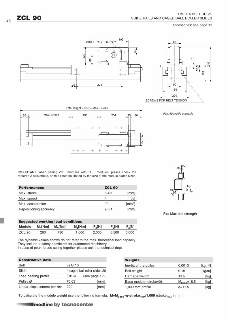
53
102
122
69
32438
196 204 15 8055
88
90
166
200
240
11850
,5
15
ZCL 90
Constructive data
Belt 32AT10 Slide 4 caged ball roller slides 20Load bearing profile E01-4 (see page 12)Pulley Ø 70.03 [mm]Linear displacement per rev. 220 [mm]
Suggested working load conditions
Weights
Inertia of the pulley 0.0013 [kgm2]Belt weight 0.19 [kg/m]Carriage weight 11.5 [kg]Base module (stroke=0) Mbase=18.5 [kg]1,000 mm profile q=11.5 [kg]
Performances ZCL 90
Max. stroke 5,450 [mm]Max. speed 4 [m/s]Max. acceleration 20 [m/s2] Repositioning accuracy ± 0.1 [mm]
ZCL 90 260 730 1,000 2,000 5,500 5,000
SCREWS FOR BELT TENSION
Module Mx[Nm] My[Nm] Mz[Nm] Fx[N] Fy[N] Fz[N]
IMPORTANT: when pairing ZC... modules with TC... modules, please check the required Z axis stroke, as this could be limited by the size of the module plates sizes.
OMEGA BELT DRIVE GUIDE RAILS AND CAGED BALL ROLLER SLIDES
Total lenght = 550 + Max. Stroke
Max. Stroke
Ø(SEE PAGE 56-57)
90x180 profile available
Accessories: see page 1148
Fx= Max belt strength
MyMz
Fz
MxFx
Fy
To calculate the module weight use the following formula: M=Mbase+q•strokemax/1,000 (strokemax in mm)
The dynamic values shown do not refer to the max. theoretical load capacity. They include a safety coefficient for automated machinery. In case of peak forces acting together please ask the technical dept

118
235
95
65
140
70
177
50030
300
180
55 20 75206 354
222
98
20
70
ZCY 180 OMEGA BELT DRIVE
DEEP ANODISED GUIDE RAILS AND SHAPED ROLLERS 49
Belt 50ATL10 Slide 4 Rollers Ø 76 [mm]Load bearing profile Sys -1G (see page 15)Pulley Ø 95.49 [mm]Linear displacement per rev. 300 [mm]
Suggested working load conditions
Weights
Inertia of the pulley 0.0067 [kgm2]Belt weight 0.34 [kg/m]Carriage weight 23.2 [kg]Base module (stroke=0) Mbase=33.5 [kg]1,000 mm profile q=12.5 [kg]
Performances ZCY 180
Max. stroke 6,750 [mm]Max. speed 4 [m/s]Max. acceleration 15 [m/s2] Repositioning accuracy ± 0.6 [mm]
ZCY 180 220 350 280 3,000 2,400 1,800
Total lenght = 710 + Max. StrokeMax. Stroke
SCREWS FOR BELT TENSION
Registered model
Module Mx[Nm] My[Nm] Mz[Nm] Fx[N] Fy[N] Fz[N]
IMPORTANT: when pairing ZC... modules with TC... modules, please check the required Z axis stroke, as this could be limited by the size of the module plates sizes.
Ø(SEE PAGE 56-57)
Accessories: see page 11
Assembly positions and load direction, see page 10
Fx= Max belt strength
MyMz
Fz
MxFx
Fy
To calculate the module weight use the following formula: M=Mbase+q•strokemax/1,000 (strokemax in mm)
The dynamic values shown do not refer to the max. theoretical load capacity. They include a safety coefficient for automated machinery. In case of peak forces acting together please ask the technical dept
Constructive data

140
70
177118
285
145
70
100
280
170
2525 9
20
20655 354 20 75
246
148
148
387
20
70
Constructive data
Belt 50 ATL 10 Slide 4 slides 2 roll. Ø 40 [mm]Load bearing profile MA 1-5 (see page 13)Pulley Ø 95.49 [mm]Linear displacement per rev. 300 [mm]
Suggested working load conditions
Weights
Inertia of the pulley 0.0067 [kgm2]Belt weight 0.34 [kg/m]Carriage weight 25 [kg]Base module (stroke=0) Mbase=36.5 [kg]1,000 mm di profile q=16.5 [kg]
ZCRQ 100 OMEGA BELT DRIVE
V-SHAPED GUIDE RAILS AND ROLLER SLIDESSUITABLE FOR VERTICAL AND HORIZONTAL ASSEMBLY
Performances ZCRQ 100
Max. stroke 5,300 [mm]Max. speed 4 [m/s]Max. acceleration 25 [m/s2]Repositioning accuracy ± 0.1 [mm]
ZCRQ 100 360 1,200 1,200 4,000 7,320 7,320
50
Total lenght = 710 + Max. StrokeMax. Stroke
Module Mx[Nm] My[Nm] Mz[Nm] Fx[N] Fy[N] Fz[N]
Pin
Ø6
IMPORTANT: when pairing ZC... modules with TC... modules, please check the required Z axis stroke, as this could be limited by the size of the module plates sizes.
Ø(SEE PAGE 56-57)
Accessories: see page 11
SCREWS FOR BELT TENSION
Fx= Max belt strength
MyMz
Fz
MxFx
Fy
To calculate the module weight use the following formula: M=Mbase+q•strokemax/1,000 (strokemax in mm)
The dynamic values shown do not refer to the max. theoretical load capacity. They include a safety coefficient for automated machinery. In case of peak forces acting together please ask the technical dept
Assembly positions and load direction, see page 10

140
70
177
487
148
148
246
2525
9
55
170
20 75
20
206 354
70
145
70
285
118
260177
100
20
Constructive data
Belt 50 ATL 10 Slide 4 caged ball roller slides 20Load bearing profile MA 1-5 (see page 13)Pulley Ø 95.49 [mm]Linear displacement per rev. 300 [mm]
Suggested working load conditions
Weights
Inertia of the pulley 0.0067 [kgm2]Belt weight 0.34 [kg/m]Carriage weight 24.4 [kg]Base module (stroke=0) Mbase=36.6 [kg]1,000 mm profile q=15.2 [kg]
ZCL 100 OMEGA BELT DRIVE
GUIDE RAILS WITH CAGED BALL ROLLER SLIDESSUITABLE FOR VERTICAL AND HORIZONTAL ASSEMBLY
Performances ZCL 100
Max. stroke 5,300 [mm]Max. speed 4 [m/s]Max. acceleration 25 [m/s2]Repositioning accuracy ± 0.1 [mm]
ZCL 100 480 1,630 1,840 4,000 7,360 8,260
51
Total lenght = 710 + Max. StrokeMax. Stroke
Module Mx[Nm] My[Nm] Mz[Nm] Fx[N] Fy[N] Fz[N]
Pin
Ø6
IMPORTANT: when pairing ZC... modules with TC... modules, please check the required Z axis stroke, as this could be limited by the size of the module plates sizes.
Ø(SEE PAGE 56-57)Accessories: see page 11
Fx= Max belt strength
MyMz
Fz
MxFx
Fy
SCREWS FOR BELT TENSION
To calculate the module weight use the following formula: M=Mbase+q•strokemax/1,000 (strokemax in mm)
The dynamic values shown do not refer to the max. theoretical load capacity. They include a safety coefficient for automated machinery. In case of peak forces acting together please ask the technical dept

A
B
177
E
F
70
20
D
120300
387
208
208
25 9
25
7535455 206
170 20
20
246
C
Constructive data ZCRQ 170 ZCERQ 170
Belt 50 ATL 10 75 ATL 10 Slide 4 slides 2 roll. Ø 40 [mm]Load bearing profile Statyca (see page 14)Pulley Ø 95.49 [mm]Linear displacement per rev. 300 [mm]
Suggested working load conditions
Weights ZCRQ 170 ZCERQ 170
ZCRQ 170 - ZCERQ 170 OMEGA BELT DRIVE
V-SHAPED GUIDE RAILS AND ROLLER SLIDESSUITABLE FOR VERTICAL AND HORIZONTAL ASSEMBLY
Performances ZCRQ 170 - ZCERQ 170
Max. stroke 5,300 [mm] Max. speed 4 [m/s] Max. acceleration 25 [m/s2]Repositioning accuracy ± 0.1 [mm]
ZCRQ 170 440 1,485 1,485 4,000 7,620 7,620ZCERQ 170 440 1,485 1,485 6,000 7,620 7,620
52
Total lenght = 710 + Max. Stroke SCREWS FOR BELT TENSION
Max. Stroke
Belt A B C D E F 50 140 70 70 118 345 205 75 164 82 82 143 379 215
Inertia of the pulley 0.0067 0.010 [kgm2]Belt weight 0.34 0.51 [kg/m]Carriage weight 27.6 32 [kg]Base module (stroke=0) Mbase=47 Mbase=51.4 [kg]1,000 mm profile q=25 q=25 [kg]
Module Mx[Nm] My[Nm] Mz[Nm] Fx[N] Fy[N] Fz[N]
Pin
Ø6
IMPORTANT: when pairing ZC... modules with TC... modules, please check the required Z axis stroke, as this could be limited by the size of the module plates sizes.
Ø(SEE PAGE 56-57)
Fx= Max belt strength
MyMz
Fz
MxFx
Fy
To calculate the module weight use the following formula: M=Mbase+q•strokemax/1,000 (strokemax in mm)
The dynamic values shown do not refer to the max. theoretical load capacity. They include a safety coefficient for automated machinery. In case of peak forces acting together please ask the technical dept
Assembly positions and load direction, see page 10

F70 E
D
120
197
280
175
C
B
A
470
208
208
7535455 206170 20
266
25 9
25
20
20
Constructive data ZCL 170 ZCEL 170
Belt 50 ATL 10 75 ATL 10Slide 4 caged ball roller slides 25Load bearing profile Statyca (see page 14)Pulley Ø 95.49 [mm]Linear displacement per rev. 300 [mm]
Suggested working load conditions
Weights ZCL 170 ZCEL 170
ZCL 170 - ZCEL 170 OMEGA BELT DRIVE
GUIDE RAILS WITH CAGED BALL ROLLER SLIDESSUITABLE FOR VERTICAL AND HORIZONTAL ASSEMBLY
Performances ZCL 170 - ZCEL 170
Max. stroke 5,300 [mm]Max. speed 4 [m/s]Max. acceleration 25 [m/s2]Repositioning accuracy ± 0.1 [mm]
ZCL 170 810 2,940 4,560 4,000 10,400 12,000ZCEL 170 810 2,940 4,560 6,000 10,400 12,000
53
Total lenght = 710 + Max. Stroke
SCREWS FOR BELT TENSIONMax. Stroke
Inertia of the pulley 0.0067 0.010 [kgm2]Belt weight 0.34 0.51 [kg/m]Carriage weight 27.6 31.6 [kg]Base module (stroke=0) Mbase=46.2 Mbase=50.2 [kg]1,000 mm profile q=24 q=24 [kg]
Module Mx[Nm] My[Nm] Mz[Nm] Fx[N] Fy[N] Fz[N]
Pin
Ø6
IMPORTANT: when pairing ZC... modules with TC... modules, please check the required Z axis stroke, as this could be limited by the size of the module plates sizes.
Belt A B C D E F 50 140 70 70 118 345 205 75 164 82 82 143 379 215
Ø(SEE PAGE 56-57) Accessories: see page 11
Fx= Max belt strength
MyMz
Fz
MxFx
Fy
To calculate the module weight use the following formula: M=Mbase+q•strokemax/1,000 (strokemax in mm)
The dynamic values shown do not refer to the max. theoretical load capacity. They include a safety coefficient for automated machinery. In case of peak forces acting together please ask the technical dept

E
F70
A t t enzione alla ta b ella dello Z c er 120 L
in basso a dest r a c on le quo t e A B C D E
c ambiano solo le quo t e della cinghia 50
120
D
300
177
B
C
A
258
258
387
50
220
150
7535455 206
25
9
25
20
246
20
Constructive data ZCRQ 220 ZCERQ 220
Belt 50 ATL 10 75 ATL 10 Slide 4 slides 3 rollers Ø 40 [mm]Load bearing profile Logyca (see page 14)Pulley Ø 95.49 [mm]Linear displacement per rev. 300 [mm]
Suggested working load conditions
Weights ZCRQ 220 ZCERQ 220
ZCRQ 220 - ZCERQ 220 OMEGA BELT DRIVE
V-SHAPED GUIDE RAILS AND ROLLER SLIDESSUITABLE FOR VERTICAL AND HORIZONTAL ASSEMBLY
Performances ZCRQ 220 - ZCERQ 220
Max. stroke 11,300 [mm]Mas. speed 4 [m/s]Max. acceleration 25 [m/s2]Repositioning accuracy ± 0.1 [mm]
ZCRQ 220 440 1,900(*) 1,485 4,000 7,620 9,500(*)ZCERQ 220 440 1,900(*) 1,485 6,000 7,620 9,500(*)
54
Total lenght = 710 + Max. Stroke Max. Stroke
SCREWS FOR BELT TENSION
Inertia of the pulley 0.0067 0.010 [kgm2]Belt weight 0.34 0.51 [kg/m]Carriage weight 26 30 [kg]Base module (stroke=0) Mbase=52 Mbase=56 [kg]1,000 mm profile q=33.6 q=34 [kg]
Module Mx[Nm] My[Nm] Mz[Nm] Fx[N] Fy[N] Fz[N]
Pin
Ø6
IMPORTANT: when pairing ZC... modules with TC... modules, please check the required Z axis stroke, as this could be limited by the size of the module plates sizes.
*
* : Please specify the roller orientation according to the barycentre of the applied load. Values corresponding to the most favourable load position.
Belt A B C D E F 50 140 70 70 118 395 255 75 164 82 82 143 429 265
Ø(SEE PAGE 56-57) Accessories: see page 11
Fx= Max belt strength
MyMz
Fz
MxFx
Fy
To calculate the module weight use the following formula: M=Mbase+q•strokemax/1,000 (strokemax in mm)
The dynamic values shown do not refer to the max. theoretical load capacity. They include a safety coefficient for automated machinery. In case of peak forces acting together please ask the technical dept
Assembly positions and load direction, see page 10

E
F70
A t t enzione alla ta b ella dello Z c er 120 L
in basso a dest r a c on le quo t e A B C D E
c ambiano solo le quo t e della cinghia 50
120
D
300
177
B
C
A
258
258
387
50
220
150
7535455 206
25
9
25
20
246
20
A t t enzione alla ta b ella dello Z c es 120 L
in basso a dest r a c on le quo t e A B C D E
c ambiano solo le quo t e della cinghia 50
F
E
D
120197280
175
C
B
A
470
258
258
7535455 206170 20
266
25 9
25
20
7020
Constructive data ZCL 220 ZCEL 220
Belt 50 ATL 10 75 ATL 10Slide 4 caged ball roller slides 25Load bearing profile Logyca (see page 14)Pulley Ø 95.49 [mm]Linear displacement per rev. 300 [mm]
Suggested working load conditions
Weights ZCL 220 ZCEL 220
ZCL 220 - ZCEL 220 OMEGA BELT DRIVE
GUIDE RAILS WITH CAGED BALL ROLLER SLIDESSUITABLE FOR VERTICAL AND HORIZONTAL ASSEMBLY
Performances ZCL 220 - ZCEL 220
Max. stroke 11,305 [mm]Max. speed 4 [m/s]Max. acceleration 25 [m/s2] Repositioning accuracy ± 0.1 [mm]
ZCL 220 810 2,940 4,560 4,000 10,400 12,000ZCEL 220 810 2,940 4,560 6,000 10,400 12,000
55
Total lenght = 710 + Max. Stroke
SCREWS FOR BELT TENSIONMax. Stroke
Inertia of the pulley 0.0067 0.010 [kgm2]Belt weight 0.34 0.51 [kg/m]Carriage weight 27.5 37.5 [kg]Base module (stroke=0) Mbase=53 Mbase=57 [kg]1,000 mm profile q=32.3 q=32.7 [kg]
Module Mx[Nm] My[Nm] Mz[Nm] Fx[N] Fy[N] Fz[N]
Pin
Ø6
IMPORTANT: when pairing ZC... modules with TC... modules, please check the required Z axis stroke, as this could be limited by the size of the module plates sizes.
Belt A B C D E F 50 140 70 70 118 395 255 75 164 82 82 143 429 265
Ø(SEE PAGE 56-57) Accessories: see page 11
Fx= Max belt strength
MyMz
Fz
MxFx
Fy
To calculate the module weight use the following formula: M=Mbase+q•strokemax/1,000 (strokemax in mm)
The dynamic values shown do not refer to the max. theoretical load capacity. They include a safety coefficient for automated machinery. In case of peak forces acting together please ask the technical dept

Holes in drive pulleys for shaft shrink-discs Registered model56
P
Ø A
P
Ø A
50 41
44 ==
60
35
==
62 51
82
==
72
104
75 75
91
60
==
==
P
ØA
\B
80= =
80
= =
102
175
60
= =
110= =
P
ØA
/B
ØB
/A
V ZP
ØA
\B
PØ
AØB
P
Ø 4
8
Ø 4
8
ØB
/A
ØA
/B
V Z
37 30,5
42 ==
42,5 P
Ø 3
4Ø
48
Ø 5
9,5
Ø 5
9,5
Ø 5
9,5
Ø 6
9
Ø 6
9
Ø 6
9
Ø 4
8
Ø 4
8
Ø 4
8
Ø 6
9
Ø 6
9
Ø 6
9
ØAØB
P
Ø 3
4
Ø 3
4Ø
B/A
ØA
/B
V Z
V Z
P
ØA
\B
ØB
/A
ØA
/B
V ZP
ØB
/A
ØA
/B
VP
Z
P
ØA
P
V
ØB
/A
ØA
/B
ØB
Z
Ø75
30° 60°
M5 Ø95
25° 65°
M5
A BM5
The motor connection is pre-engineered directly on the drive head by means of a removable flange, but integrated in the actual head. The drive shaft and/or the driven shaft are locked into the pulley by shrink-discs. (The gearbox can be easily removed without disassembling the head). Please see page 10 to identify the desired motor side (left or right); page 56 for shrink-disc and flange diameter and page 11 for the order code setting. Out-of-standard diameters are available upon request.
:input A output B :input B output A
gearbox entry driven shaft sideSeries KC 30-50
Series MC 65
Serie MC 80
Series MC 105 - TC 180
Series TC 170/200 - TC 220 - TC 280 - TC 360
Series ZC 60 - ZC 90
Series ZC 100 - ZCY 180 - ZC 170-220 - ZCE 170-220
KCH 30
KCH 50
KCH 30
KCH 50
30°
A
25°
60°
B
65°
75
Ø
95

Standard machining for planetary gearboxes - MP or MPTR, LP, EP series.Machining is performed directly on the removable flange in a symmetric position, suitable for both sides.
Gearbox adapting plates
Ex. module: TC 280
Phosphating of drive and driven pulleys.
Ex. module: MC 105
Drilled flange: code EBlind flange: code X
Module A Ø [mm] B Ø [mm] V [mm] P [mm] Z [mm]
12H7 40 34 4 14H7 68 34 4 12H7 67 34 0 14H7 67 34 0 16H7 80 52.4 1 19H7 80 49.4 1 20H7 80 49.4 1 19H7 105 49 13.5 25H7 105 51 8 25H7 117 54.5 12.5 32H7 117 57.5 7 25H7 142 79.5 12.5 32H7 142 82.5 7 40H7 142 82.5 7 16H7 100 62.4 0 19H7 100 62.4 0 20H7 100 62.4 0 25H7 108 48.5 11.5 32H7 108 52.5 6 25H7 108 48.5 11.5 32H7 108 52.5 6 40H7 108 52.5 6 25H7 143 65 12 32H7 143 95 12 40H7 143 95 12
MC 105 - TC 180
MC 80
TC 170 - TC 200
TC 220 - TC 280 - TC 360
ZC 60 - ZC 90
ZC 100 - ZCY 180
ZC 170 - 220
ZCE 170 - 220
MC 65 - TC 100
Linear module Gearbox code Size
KCH30 - KCH50
Series D Ø G MC 65 LP 050 35 12 44 KC 30-50 EP55 32 12 40 MP053 32 12 40 MC 80-105 - ZC 60 MPTR080 50 19 65 LP070 52 16 62 ZC 90 EP75 AA 40 14 52 MC 105 - TC-ZC 100 MPTR105 70 25 85 MC 105 - TC 180 LP090 68 22 80 EP90 TT 50 19 65 MPTR130 80 32 110 TC 170-360 LP120 90 32 108 ZC 170-220 EP120 TT 70 25 85
57

Connecting shafts for parallel modulesWe can supply standard hollow shaft connections, according to your application requirements.Please specify the type of module to be connected, together with speed, “L” centre-distance, working and peak torques, accuracy.Some simplified solutions with solid shafts are available for low-speed applications and with “L” of up to 2,000 mm.If high-speeds and/or “L” of more than 2,000 mm are needed, please ask our technical dept. for the shaft scaling.
The complete kit includes all the components needed to make the connection: tube, shrink-discs, shaft crop ends for connection between pulleys and shrink-discs, any supports.Tube material: 6060 aluminium alloyThe customer is responsible for ensuring compliance with accident prevention rules in relation to all rotating parts.Type 1 - Elastic joint connecting shafts, normally suitable for low-speeds
Type 2 - Stainless steel blade joint connecting shafts, suitable for backlash-free transmissions
Type 3 - Stainless steel blade joint connecting shafts and pedestal bearings, suitable for backlash-free transmissions
R(*) K F N S Lmax MTwork [Nm] Mom.Inertia. [Kgm2] Type 1: Code/L Type 2: Code/L Type 3: Code/L
40 67 55 20 200 6,200 20 0.0028 + 0.46 x L. x10-6 436.0948 436.0957 436.096550 81 65 25 235 6,300 35 0.0092 + 0.66 x L. x10-6 436.0949 436.0958 436.096650 93 80 25 235 6,300 70 0.0161 + 1.34 x L. x10-6 436.0951 436.0971 436.097470 104 95 25 235 6,400 100 0.0293 + 2.93 x L. x10-6 436.0952 436.0960 436.0968 80 126 120 25 250 6,400 190 0.0793 + 4.5 x L. x10-6 436.0955 436.0963 436.098490 143 - - - 6,500 300 0.1456 + 6.53 x L. x10-6 - 436.0986 436.0987110 185 - - - 6,000 420 0.3499 + 12.3 x L. x10-6 436.0144 436.0145 436.0146
Preliminary table n° g. max
The S value can vary by ± 20%, Lmax by ± 3%, according to the chosen type. Please contact our technical dept.
58
Lenght

Material: aluminium alloy 6082
Mounting brackets
59
Make sure that all the components are locked in place with the appropriate screws. The recommended tightening torque for pin locking screws and nuts is 50 Nm.
Spare rollers with pins
KC 30 30x30 25 25 - 6.7 17 6.8 10.6 10 18 40 415.1105 MC 65 67x65 25 50 25 6.7 20 6.8 13.5 10 18 87 415.0388 MC 80 80x80 25 50 25 6.7 25 6.8 18.6 10 18 100 415.0760 KC 50, TC-ZC 100 25 50 25 6.7 27 6.8 20.6 10 18 120 415.0764 MC 105 105x105 30 50 25 9 30 9.5 23.6 12 22 129 415.0761 TC 180 180x90 30 50 25 9 25 9.5 18 12 25 204 415.0773 TC 170 120x170 198TC 200 120x200 30 90 50 11 40 11 28.3 14 25 228 415.0762 TC 220 120x220 248 TC 280 170x280 30 90 50 11 20 11 11.3 14 25 308 415.0763 TC 280Vert. 280x170 30 90 50 11 20 11 13.5 14 25 198 915.1174
Module type bxh A L T d H P C F B M Code
Roller Cw [N] C0w[N] Fr amm.[N] V max.Ø30 5,000 3,000 1,350 7 m/sØ40 9,800 6,200 2,600 7 m/sØ52 15,800 10,500 4,400 6 m/sØ62 21,100 14,500 5,600 5 m/s
Max. load factors for hardened and tempered guides
Max. load factors for hardened guidesRoller Cw [N] C0w[N] Fr amm.[N] V max.Ø30 5,000 3,000 400 2 m/sØ40 9,800 6,200 800 13 m/sØ52 15,800 10,500 1,400 2.5 m/sØ62 21,100 14,500 1,900 2 m/s Spare roller with pin Weight [kg] CodeØ30 Concentric 0.02 406.0056Ø40 Concentric 0.22 205.0464Ø40 Eccentric (± 0.75 mm) 0.25 205.0463Ø52 Concentric 0.4 205.0163Ø62 Concentric 0.55 205.0165

Accessories and screwsAssembly brackets
Suitable for all the modules
Material: natural, anodised anticorodal alloy.
Material: galvanised steelSuitable for ZC series
Thread Code
A B C D E S Txt ØM Ø M45 45 20 25 25 5 20x6.5 6 A30-76 A 30-86
35 25 20 19 15 5 20x6.5 4 A30-54 A 30-64
35 25 20 19 15 5 20x6.5 5 A30-55 A 30-65
35 25 20 19 15 5 20x65 6 A30-56 A 30-66
25 25 15 14 15 4 13.5x5.5 3 B30-53 B 30-6325 25 14 14 15 4 13.5x5.5 4 B30-54 B 30-6425 25 15 14 15 4 13.5x5.5 5 B30-55 B 30-6525 25 15 14 15 4 13.5x5.5 6 B30-56 B 30-66
Color Code A /Lenght
grey Cod.A39-25/5000black Cod.A39-26/5000orange (on request) Cod.A39-25/6000 A
M x L Code B M x L Code A
M 6x15 B35-15 M8x20 A35-20M 6x20 B35-20 M8x25 A35-20M 6x30 B35-30 M8x30 A35-30M 6x40 B35-40 M8x40 A35-40 M8x60 A35-60
Ext. thread Int. a L Key Code
M16 M 6 25 6 A33-26M16 M 8 25 8 A33-28M16 M 10 25 10 A33-20M20 M 6 25 6 207.1892M20 M 8 25 8 207.1893M20 M 10 25 10 207.1894M20 M 12 25 12 207.2288
Filler strips
T Bolts
Threaded inserts (suitable for the ZC series)
PVC filler strips, grey or black L=5,000 - 6,000 mm for any longitudinal 8 mm slot
Suitable for series: KC 50, MC 80-105, ZC 60-90-100-170, TC 100-180
Assembly in longitudinal slots. Material: galvanised steel. Can be inserted through the profile slot.
Code A: KC 50, MC 80-105, ZC 60-90-100-170, TC 100-180Code B: KC 30, MC 65
C t
CE
BØ/M
A
S
1.5
7.5
10
L
M
9.6
D
T
60

Front insertable nuts and plates
Single plate Code A Code B
M5 A32-55 B32-55M6 A32-65 B32-65M8 A32-85 B32-85
Size
Base Module D H L L1 T MC 105, ZC 100 14 7.8 20 40 30MC 80 11 4.1 20 40 30
Double plate Code A Code B
M6 A32-67 B32-67
Thread Code
M5 209.2431M6 209.2432M8 209.2433
Thread Code B
M3 BD31-30M4 BD31-40M5 BD31-50M6 BD31-60
Thread Code B
M4 B32.40M5 B32.50M6 B32.60
Simple nut
Spring nut Plate suitable for every kind of module (8 mm slot).
Material: nut in galvanised steel welded to the harmonic steel spring. The B series can also be inserted through the slot.
Code A: KC 50, MC 80-105, ZC 60-90-100-170, TC 100-180Code B: KC 30, MC 65
Material: galvanised steel.Insert through the end of the profile.Suitable for series:
KC 50, MC 80-105, ZC 60-90-100-170, TC 100-180
Material: galvanised steel, harmonic steel spring. To be inserted through the slot. Suitable for series:
KC 30, MC 65
Materiale: galvanised steel. To be inserted through the slot. Suitable for series:
KC 30, MC 65
Front insertable spring nut
Simple Nut
D M
TL1
L H
8
12 6
M
1
4.1
M
11
8
12
61
314
11 M

Threaded nuts and plates
Thread CodeM4 A32-40M5 A32-50M6 A32-60M8 A32-80Molla 211.1061
Material: galvanised steel. Insert through the end of the profile. Retaining spring upon request.
TC-ZC 100, TC 180, ZCY 180
Flat nut
62
18,2
4
21
M
21
21
4
M
18
18
8,5
M==
Semi-rounded threaded inserts with spring
Threaded plate for base profile 45, 50 and 60. Material: galvanised steel. Important: to be inserted through the longitudinal slots before assembling.
Suitable for series:TC-ZC 100, ZCY 180, TC 170-180-200-220-360, ZC 170-220
Spring CodeSuitable for all inserts 18x18 101.0732
Plastic compound spring for vertical positioning of insert.
18
18
8,5
M==
Thread Code 18x18 Code 20x20M4 209.0031 209.0023M5 209.0032 209.0019M6 209.0033 209.1202M8 209.0034 209.0467

20 11
18 12
M
Thread Type L CodeM10 1-hole plate 40 215.0477M12 1-hole plate 40 209.1281M10 1-hole plate 20 209.1277M10 2-holes plate* 80 209.1776M10 3-holes plate* 150 209.1777M10 4-holes plate* 200 209.1778M10 5-holes plate* 250 209.1779M10 6-holes plate* 300 209.1780M10 7-holes plate* 350 209.1781
Alignment nuts
Thread Code
M5 215.1768M6 215.1769M8 215.1770M10 215.2124
Thread Code
M5 215.1771M6 215.1772M8 215.1773M10 215.2125
Alignment nut for slot 12.5 mm
Nuts for steel guide rails
Alignment nut for slot 12.5 mm front insertable
Threaded nuts and plates
Material: galvanised steel. Suitable for series:TC 170-200-280-360 and ZC 170-220
Material: galvanised steel. Suitable for series:TC 170-200-280-360 and ZC 170-220
M12 (CH19) hexagonal-head screws can be used as stud bolts in profiles with 12.5 mm slots.
Material: galvanised steel. Suitable for series:TC 170-200-220-280-360 and ZC 170-220
* Hole centre-distance: 50 mm.
L
25 50 50 25
Code 209.0298
Alignment nuts.V-shaped guide rail: 35x16Profile with slot 8 mm. Series: TC-ZC 100, TC 180
Material: galvanised steel.
Code 209.1855
Alignment nuts.V-shaped guide rail: 35x16Profile with slot. 12.5 mm. Series: TC 170-200-220-280-360 e ZC 170-220
63
8
12,5
M6
30
20
20
8,7
30
20
10
8
M6
6,5
30°11
12
12
M
10
M
20
L
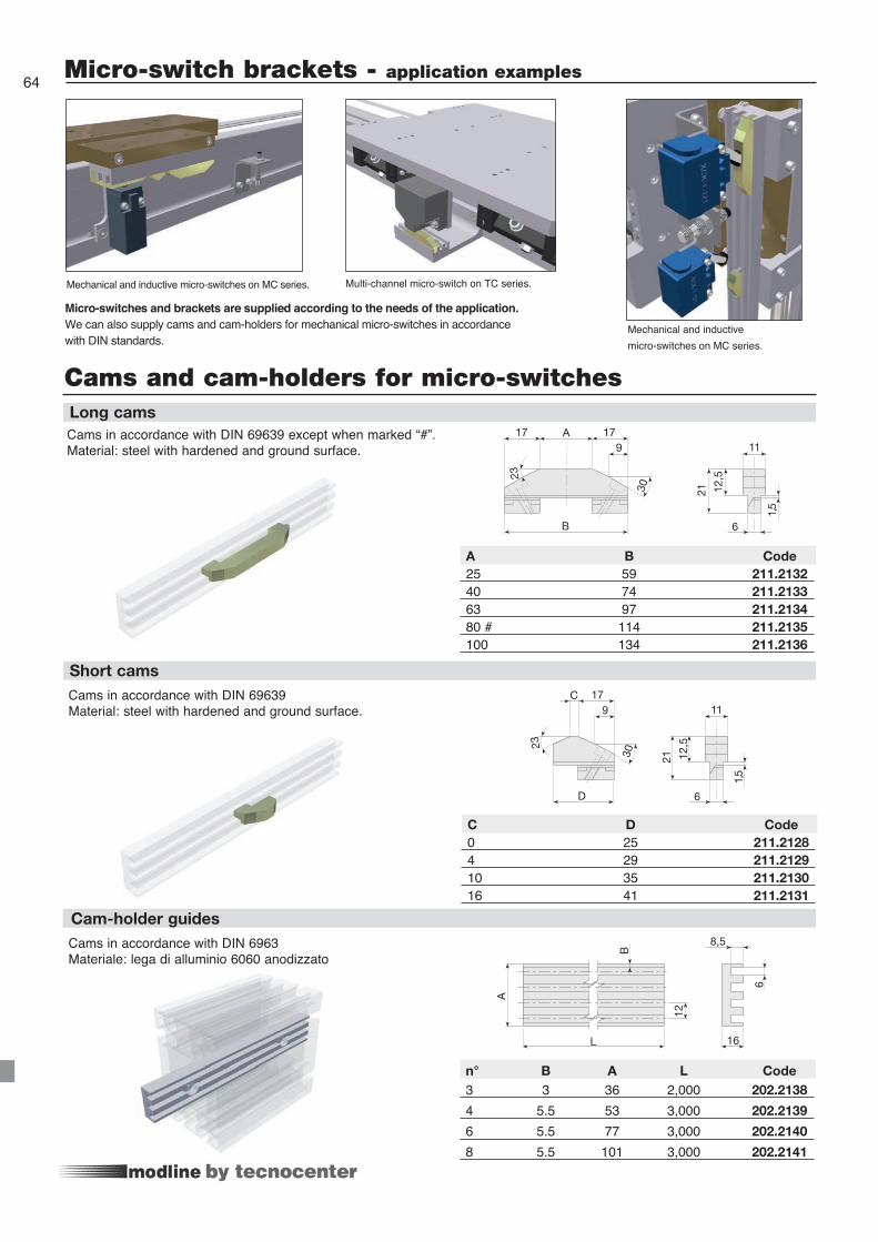
1,5
6
11
12,5
21
D
23
C 179
30B
A
L
8,5
12
6
16
1,5
6
11
12,5
21
B
A 17179
23
30
Cams in accordance with DIN 69639Material: steel with hardened and ground surface.
Cams in accordance with DIN 6963Materiale: lega di alluminio 6060 anodizzato
A B Code25 59 211.213240 74 211.213363 97 211.213480 # 114 211.2135100 134 211.2136
Long cams
Short cams
Cam-holder guides
n° B A L Code 3 3 36 2,000 202.2138
4 5.5 53 3,000 202.2139
6 5.5 77 3,000 202.2140
8 5.5 101 3,000 202.2141
C D Code0 25 211.21284 29 211.212910 35 211.213016 41 211.2131
Cams in accordance with DIN 69639 except when marked “#”. Material: steel with hardened and ground surface.
64 Micro-switch brackets - application examples
Mechanical and inductive micro-switches on MC series.
Mechanical and inductive micro-switches on MC series. Multi-channel micro-switch on TC series.
Micro-switches and brackets are supplied according to the needs of the application. We can also supply cams and cam-holders for mechanical micro-switches in accordance with DIN standards.
Cams and cam-holders for micro-switches

65Special variantsReader system with magnetic scale and sensor
Twin drive head
Rotatable load-bearing profile to fully exploit the moment of inertia
Precision profile machining
Version with drive head on both sides.
Profiles can be machined along their entire length, to provide the required precision or according to application specifications. Example: for linear motors.
The load-bearing profile can be rotated in order to change the overall dimensions, or to fully exploit the moment of inertia.
The magnetic scale is applied to the body of the module using a supporting and protective profile.Precision of between ± 0.015 and ± 0.05 mmMax speed = 4 ÷ 10 m/s (depending on the type)

66 Special applications
Guard system consisting of a magnetic stainless steel foil to protect the belt from dust and external agents (code: LI), which is attached to the profile. NB: Avoid the use of a metallic band in the presence of ferrous filings. Optional.
Example of horizontal transfer with integrated belt and transmission pulley support, in an intermediate position, all incorporated inside the profile. (Registered design)Special feature: note the compensating cylinders and the horizontal cylinder for the different travel of carriage no. 3.
Belt protection for series MC 65 - 80 - 105
TC multi-carriage linear modules with intermediate belt transmission
In some applications which involve the use of high speeds and accelerations, the assembly of linear units having a vertical pulley axis and a centre-distance of more than 4 m may force the toothed belt and result in the need for premature maintenance. In this case we suggest you mount the pulleys and the belt in a horizontal position. The modification as shown in the figure below can be requested for the MODLINE TCS series. Optional.
corsa
TC series of linear modules with pulley axis turned at 90°

67
E
G
corsaC + corsa
FD
Anti-drop safety device with pneumatic brake systemAnt-droop safety devices, available in a range of sizes, are supplied according to the type of application. For instance, they can act as a mechanical stop to block the free-falling load at any stroke point, or as a lock in static conditions at any position. Two-way blocking occurs following an unexpected pressure drop. A mechanical safety release system is available upon request (patented). Catalogue available upon request. The kit includes: braking device and rod with relative supports, micro-switch and solenoid valve.Operating pressure 3-6 Bar. With no pressure = locked.
A 236.0018 / 1,200 / ...A 236.0018 / 1,900 / ... A 236.0018 / 3,000 / ... A 236.0018 / 5,400 / ...A 236.0018 / 7,500 / ... A 236.0018 / 12,000 / ...
1- Static rod blocking device Type Code Rod blocking force [N] Stroke [mm]
Pneumatic braking device
Hardened chrome-plated cylindrical rod
Type AStatic
Type BDinamic, for free-fallingloading
Emergency brake for free-falling load.
Safety lock-pin (stopper cylinders)Lock-pin devices, available in two sizes, suitable to block the vertical axes in the safety position during horizontal movements. (e.g.: maintenance). The safety lock-pins are provided with a through rod.Select the size according to the load. The kit includes: drilled plate for rod, stopper cylinder, micro-switch.Max. operating pressure: 10 bar.
ØD rod stroke C E F G Kit Code20 20 60.5 50 38 16 236.002132 30 - - - - 236.0022
1- Lock-pin device
Special plate upon request
20 60 100 39
32 60 100 39
2- Accessory: drilled plate for rod ØD rod Base Lenght Thickness
B 236.0019 / 3,000 / ...B 236.0019 / 5,400 / ...B 236.0019 / 7,500 / ...B 236.0019 / 12,000 / ...
1- Dynamic rod blocking device Type Code Rod blocking force [N] Stroke [mm]
Micro-switch
Drilled plate

68 Index
1010732 62
2020342 15
2021146 14
2021147 14
2021753 14
2022138 64
2022139 64
2022140 64
2022141 64
2022184 14
2050163 59
2050165 59
2050463 59
2050464 59
2071892 60
2071893 60
2071894 60
2072288 60
2090019 62
2090023 62
2090298 63
2090467 62
2091202 62
2091277 63
2091281 63
2091776 63
2091777 63
2091778 63
2091779 63
2091780 63
2091781 63
2091855 63
2092431 61
2092432 61
2092433 61
2111061 62
2112128 64
2112129 64
2112130 64
2112131 64
2112132 64
2112133 64
2112134 64
2112135 64
2112136 64
2150477 63
2151768 63
2151769 63
2151770 63
2151771 63
2151772 63
2151773 63
2152124 63
2152125 63
2360018 67
2360019 67
2360021 67
2360022 67
3020001 17
4060056 59
4150388 59
4150760 59
4150761 59
4150762 59
4150763 59
4150764 59
4150773 59
4151105 59
4360144 58
4360145 58
4360146 58
4360948 58
4360949 58
4360951 58
4360952 58
4360955 58
4360957 58
4360958 58
4360960 58
4360963 58
4360965 58
4360966 58
4360968 58
4360971 58
4360974 58
4360984 58
4360986 58
4360987 58
7400568 13
9151174 59
A30-54 60
A30-55 60
A30-56 60
A30-64 60
A30-65 60
A30-66 60
A30-76 60
A30-86 60
A32-40 62
A32-50 62
A32-55 61
A32-60 62
A32-65 61
A32-67 61
A32-80 62
A32-85 61
A33-20 60
A33-26 60
A33-28 60
A35-20 60
A35-25 60
A35-30 60
A35-40 60
A35-60 60
A39-25/5000 60
A39-25/6000A 60
A39-26/5000 60
B30-53 60
B30-54 60
B30-55 60
B30-56 60
B30-63 60
B30-64 60
B30-65 60
B30-66 60
B32-40 61
B32-50 61
B32-55 61
B32-60 61
B32-65 61
B32-67 61
B32-85 61
B35-15 60
B35-20 60
B35-30 60
B35-40 60
BD31-30 61
BD31-40 61
BD31-50 61
BD31-60 61
E01-4 12
E01-5 13
F01-1 13
M 65X67 12
M 80X80 12
M 105X105 12
MA1-2 13
MA1-4 13
MA1-5 13
MCH 105 21
MCH 65 17
MCH 80 19
MCHH 105 22
MCR 105 20
MCR 65 16
MCR 80 18
MCS 105 21
MCS 65 17
MCS 80 19
MTR 105 24
MTR 80 23
MVH 105 25
MVHH 105 26
MVR 105 24
MVR 80 23
MVS 105 25
TCG 100 30
TCG 180 32
TCH 100 31
TCH 170 35
TCH 180 33
TCH 200 37
TCH 220 39
TCH 280 41
TCH 360 43
TCRQ 170 34
TCRQ 180 32
TCRQ 200 36
TCRQ 220 38
TCRQ 280 40
TCRP 280 40
TCRP 360 42
TCS 100 31
TCS 170 35
TCS 180 33
TCS 200 37
TCS 220 39
TCS 280 41
TCS 360 43
TVH 180 27
TVS 170 28
TVS 220 29
ZCEL 170 53
ZCEL 220 55
ZCERQ 170 53
ZCERQ 220 54
ZCG 60 44
ZCG 90 46
ZCL 100 51
ZCL 170 53
ZCL 220 55
ZCL 60 45
ZCL 90 48
ZCRQ 100 50
ZCRQ 170 52
ZCRQ 220 54
ZCRR 90 47
ZCY 180 49
Code page Code page Code page Code page Code page Code page

Modline Tecline
SysStructural profiles
Systems
Te product rangehas been studied so as to promote
advantageous, competitivemodular integration.
Request our assistance to discover interesting
solutions to all your needsin the field of linear
transfer.