benchmarking hand and grasp resilience to dynamic loads
TRANSCRIPT
IEEE ROBOTICS AND AUTOMATION LETTERS. PREPRINT VERSION. ACCEPTED DECEMBER, 2019 1
Benchmarking Hand and Grasp Resilience to Dynamic LoadsFrancesca Negrello1, Werner Friedl3, Giorgio Grioli1, Manolo Garabini 2, Oliver Brock4,
Antonio Bicchi 1,2, Maximo A. Roa3, Manuel G. Catalano1
Abstract—In this work, we investigate the behavior of artificialhands under impulsive load conditions. Resilience to impacts hasbeen seldom considered in grasp and manipulation literatureand benchmarks, although it is one of the most relevant issuesin a number of applications involving physical interactions withunstructured environments, in prosthetic as well as in roboticmanipulation. We focus on two research questions: the capabilityof hands to withstand impacts before being damaged (HandResilience) and before losing the grasp on a object (GraspResilience). To these aims, we introduce an evaluation framework,including a precisely defined experimental set-up and test proce-dure. The proposed methodology, metrics, and test variables arediscussed through analytical evaluation and with experimentaldata extracted from the testing of three different hand designs.
Index Terms—Benchmarking, hand, grasp and manipulation,mechanical design
I. INTRODUCTION
THE aim of our study is to define a set of test methodsto characterize the behavior of robotic hands under
impulsive load conditions, i.e. under impacts. Our work ismotivated by the fact that real-world scenarios often involveharsh and irregular physical interactions with the environment(i.e. search and rescue, craft and sports activities). Thus, thecapability of robotic hands to withstand both moderate andsevere impacts is a necessity for the effective deploymentof reliable robotic solutions in real-world tasks, consideringhumanoids and bionic limbs as well [1]. These proposed testmethods will accelerate the development of robotic hands forreal-world applications. We focus on two research questions:1) how to quantify physical robotic hands robustness (HandResilience) and 2) how an impact affects the grasp (GraspResilience).
In the last decade, the growing popularity of soft robotichands has increased the end-effectors’ capability to cope with
Manuscript received: August, 13, 2019; Revised October, 19, 2019; Ac-cepted December, 3, 2019.
This paper was recommended for publication by Editor Han Ding uponevaluation of the Associate Editor and Reviewers’ comments.
This work is supported by the European Union’s Horizon 2020 researchprogram under the projects SOMA (No. 645599), Soft Pro (No. 688857), andNatural Bionics (No. 810346), and by the German Research Foundation - DFGunder Germany Excellence Strategy – EXC 2002/1 “Science of Intelligence”(No. 390523135). The content of this publication is the sole responsibilityof the authors. The European Commission or its services cannot be heldresponsible for any use that may be made of the information it contains.
1 Istituto Italiano di Tecnologia, Via Morego 30, 16163 Genova, Italy,[email protected].
2 Centro di Ricerca E. Piaggio e Dipartimento di Ingegneriadell’Informazione, Universita di Pisa, 56126 Pisa, Italy.
3 German Aerospace Center (DLR), Institute of Robotics and Mechatronics,82234 Wessling, Germany.
4 Robotics and Biology Laboratory, Technische Universitat Berlin, 10623Berlin, Germany.
Digital Object Identifier (DOI): see top of this page.
(a)Ball mass (g) Max speed (km/h) Energy (J)
Soccer 450 180 562Volleyball 280 132 188Golf 45.93 349 215Baseball 149 169 164Tennis 59.4 263 158
(b)
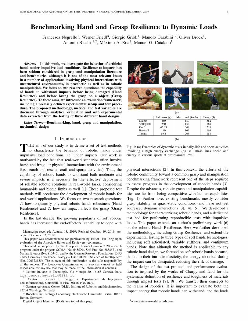
Fig. 1: (a) Examples of dynamic tasks in daily-life and sport activitiesinvolving a high energy exchange. (b) Ball mass, max speed andenergy in various sports at professional level.1
physical interactions [2]. In this context, the efforts of therobotic community toward a common grasp and manipulationbenchmarking framework represent one of the steps requiredto assess progress in the development of robotic hands [3].Despite the advances, robotic grasp and manipulation capabil-ities are far from being competitive with human capabilities(Fig. 1). Furthermore, existing benchmarks mostly considergrasp stability in quasi-static conditions, and have not yetaddressed dynamic interactions [3], [4], [5]. We developed amethodology for characterizing robotic hands, and a dedicatedtest bed for performing reproducible tests with impulsiveloads. This paper extends an author’s preliminary work [6]on the robotic Hands Resilience. Here we further developedthe methodology, including Grasp Resilience, and extend theexperimental testing to three types of soft hands technologies,including soft articulated, variable stiffness, and continuumhands. Note that although the method is applicable to anyrobotic hand design, we focused on soft robotic hands because,thanks to their intrinsic elasticity, the energy absorbed duringthe impact can be dissipated, reducing the risk of damage.
The design of the test protocol and performance evalua-tion is inspired by the works of Charpy and Izod for thesystematic definition of resilience and toughness of materialsthrough impact tests [7], [8]. We transfer their concepts tothe realm of robotics. It is important to evaluate both theimpact energy that robotic hands can withstand, and the loads
1www.guinnessworldrecords.com
2 IEEE ROBOTICS AND AUTOMATION LETTERS. PREPRINT VERSION. ACCEPTED DECEMBER, 2019
they transfer to the structure. Defining these characteristicscan lead to design modifications that help avoid damage tothe robot hand and supporting components (e.g. actuators,Force/Torque sensors). In the case of prosthetic applications,measuring these characteristics can also lead to designs thatreduce discomfort to the user. The proposed test consists ofperforming repeatable impacts through a sensorized pendulum.For testing Hand Resilience, the end of the pendulum collideswith the hand, while for Grasp Resilience the impact occurson an object grasped by the hand. Through the direct measureof pendulum position and forces at the pendulum tip and thehand’s base, we can evaluate both the energy absorbed duringthe impact and the transmissibility of the hand system.
To fully characterize Hand and Grasp Resilience, we con-sider a number of parameters, including whether the systemis stiff or soft, the actuation type and finger couplings wherethe impact happens, the portion of the hand involved (i.e. oneor more fingers in contact), in which direction the hand isloaded, and the size of the object. Finally, to facilitate theadaptation of the proposed testing method by other researchers,we include in the supplementary material the test protocol anda data report template. We also publish the test-bed design onthe Natural Machine Motion Initiative platform2 (NMMI) [9].
The paper is organized as follows: Sec. II presents the devel-oped framework for Resilience characterization, discussing theproposed methodology, metrics, test variables, test bench, anddata representation. Sec. III-IV report the experimental resultsof Grasp and Hand Resilience test for the three hands tested,and discuss the effect of the main test parameters. Lastly,Sec. V presents the main findings and open challenges.
II. METHODOLOGY AND METRICS
A. Methodology
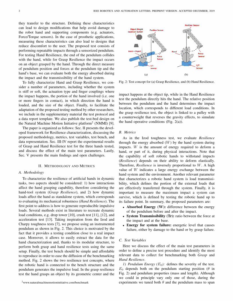
To characterize the resilience of artificial hands in dynamictasks, two aspects should be considered: 1) how interactionsaffect the hand grasping capability, therefore considering thehand-tool system (Grasp Resilience), and 2) how dynamicloads affect the hand as standalone system, which correspondsto evaluating its mechanical robustness (Hand Resilience). Thefirst point to address is how to generate reproducible impulsiveloads. Several methods exist in literature to recreate dynamicload conditions, e.g. drop tower [10], crash test [11], [12], andacceleration test [13]. Taking inspiration from the Izod andCharpy toughness tests [7], we propose using an instrumentedpendulum as shown in Fig. 2. This choice is motivated by thefact that it provides a testing condition close to a real impactcase. Moreover, it allows to easily extract the data for thehand characterization and, thanks to its modular structure, toperform both grasp and hand resilience tests using the samesetup. Finally, the test bench should be simple and affordableto reproduce in order to ease the diffusion of the benchmarkingmethod. Fig. 2 shows the two resilience test concepts, wherethe robotic hand is connected to the bench structure and thependulum generates the impulsive load. In the grasp resiliencetest the hand grasps an object by its geometric center and the
2www.naturalmachinemotioninitiative.com/benchmark
(a) (b)
Fig. 2: Test concept for (a) Grasp Resilience, and (b) Hand Resilience.
impact happens at the object tip, while in the Hand Resiliencetest the pendulum directly hits the hand. The relative positionbetween the pendulum and the hand determines the impactlocation, which corresponds to different load conditions. Inthe grasp resilience test, the object is linked to a pulley witha counterweight that reverses the gravity effects, to simulatethe hand operative conditions (Fig. 2(a)).
B. Metrics
As in the Izod toughness test, we evaluate Resiliencethrough the energy absorbed (W ) by the hand system duringimpacts. W is the amount of energy required to deform ahand, or part of it, during physical interactions. Note thatthe capability of soft robotic hands to withstand impacts(Resilience) depends on their ability to deform elastically.Therefore, Resilience is inversely proportional to W . A highvalue of W indicates a large energy exchange between thehand system and the environment. Another relevant parameterthat characterizes a robotic hand system is load transmissi-bility, which defines the portion of the external loads thatare effectively transferred through the system. Finally, it isimportant to measure the maximum impact a system cansurvive, which is defined by testing the robotic hand up toits failure point. In summary, the proposed parameters are:
• Absorbed Energy (W): difference between the energyof the pendulum before and after the impact.
• System Transmissibility (Tr): ratio between the force atthe impact and at the base.
• Energy for system failure: energetic level that causesfailure, either by damage to the hand or by grasp failure.
C. Test Variables
Here we discuss the effect of the main test parameters inorder to define a precise test procedure and identify the mostrelevant data to collect for benchmarking both Grasp andHand Resilience.
1) Pendulum Energy (E0): defines the severity of the test.E0 depends both on the pendulum starting position (θ inFig. 2) and pendulum properties (mass and length). Althoughwe could in principle vary only one of those, during theexperiments we tuned both θ and the pendulum mass to span
NEGRELLO et al.: BENCHMARKING HAND AND GRASP RESILIENCE TO DYNAMIC LOADS 3
(a) (b)
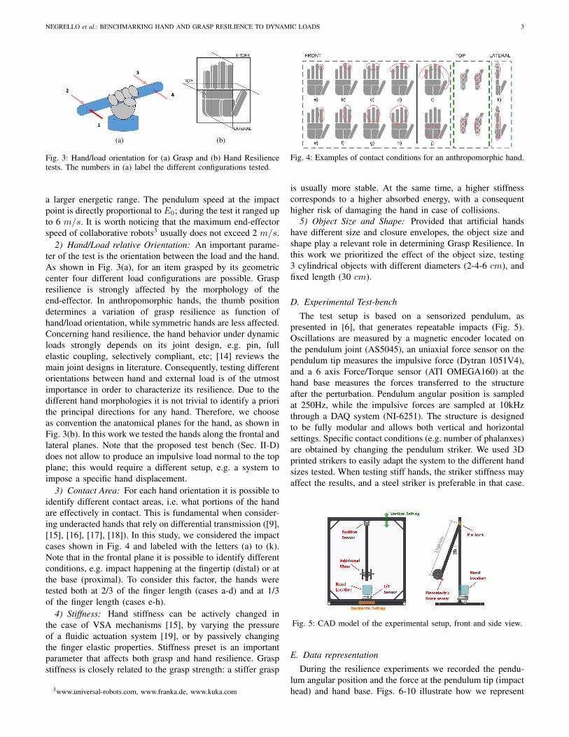
Fig. 3: Hand/load orientation for (a) Grasp and (b) Hand Resiliencetests. The numbers in (a) label the different configurations tested.
a larger energetic range. The pendulum speed at the impactpoint is directly proportional to E0; during the test it ranged upto 6 m/s. It is worth noticing that the maximum end-effectorspeed of collaborative robots3 usually does not exceed 2 m/s.
2) Hand/Load relative Orientation: An important parame-ter of the test is the orientation between the load and the hand.As shown in Fig. 3(a), for an item grasped by its geometriccenter four different load configurations are possible. Graspresilience is strongly affected by the morphology of theend-effector. In anthropomorphic hands, the thumb positiondetermines a variation of grasp resilience as function ofhand/load orientation, while symmetric hands are less affected.Concerning hand resilience, the hand behavior under dynamicloads strongly depends on its joint design, e.g. pin, fullelastic coupling, selectively compliant, etc; [14] reviews themain joint designs in literature. Consequently, testing differentorientations between hand and external load is of the utmostimportance in order to characterize its resilience. Due to thedifferent hand morphologies it is not trivial to identify a priorithe principal directions for any hand. Therefore, we chooseas convention the anatomical planes for the hand, as shown inFig. 3(b). In this work we tested the hands along the frontal andlateral planes. Note that the proposed test bench (Sec. II-D)does not allow to produce an impulsive load normal to the topplane; this would require a different setup, e.g. a system toimpose a specific hand displacement.
3) Contact Area: For each hand orientation it is possible toidentify different contact areas, i.e. what portions of the handare effectively in contact. This is fundamental when consider-ing underacted hands that rely on differential transmission ([9],[15], [16], [17], [18]). In this study, we considered the impactcases shown in Fig. 4 and labeled with the letters (a) to (k).Note that in the frontal plane it is possible to identify differentconditions, e.g. impact happening at the fingertip (distal) or atthe base (proximal). To consider this factor, the hands weretested both at 2/3 of the finger length (cases a-d) and at 1/3of the finger length (cases e-h).
4) Stiffness: Hand stiffness can be actively changed inthe case of VSA mechanisms [15], by varying the pressureof a fluidic actuation system [19], or by passively changingthe finger elastic properties. Stiffness preset is an importantparameter that affects both grasp and hand resilience. Graspstiffness is closely related to the grasp strength: a stiffer grasp
3www.universal-robots.com, www.franka.de, www.kuka.com
Fig. 4: Examples of contact conditions for an anthropomorphic hand.
is usually more stable. At the same time, a higher stiffnesscorresponds to a higher absorbed energy, with a consequenthigher risk of damaging the hand in case of collisions.
5) Object Size and Shape: Provided that artificial handshave different size and closure envelopes, the object size andshape play a relevant role in determining Grasp Resilience. Inthis work we prioritized the effect of the object size, testing3 cylindrical objects with different diameters (2-4-6 cm), andfixed length (30 cm).
D. Experimental Test-bench
The test setup is based on a sensorized pendulum, aspresented in [6], that generates repeatable impacts (Fig. 5).Oscillations are measured by a magnetic encoder located onthe pendulum joint (AS5045), an uniaxial force sensor on thependulum tip measures the impulsive force (Dytran 1051V4),and a 6 axis Force/Torque sensor (ATI OMEGA160) at thehand base measures the forces transferred to the structureafter the perturbation. Pendulum angular position is sampledat 250Hz, while the impulsive forces are sampled at 10kHzthrough a DAQ system (NI-6251). The structure is designedto be fully modular and allows both vertical and horizontalsettings. Specific contact conditions (e.g. number of phalanxes)are obtained by changing the pendulum striker. We used 3Dprinted strikers to easily adapt the system to the different handsizes tested. When testing stiff hands, the striker stiffness mayaffect the results, and a steel striker is preferable in that case.
Fig. 5: CAD model of the experimental setup, front and side view.
E. Data representation
During the resilience experiments we recorded the pendu-lum angular position and the force at the pendulum tip (impacthead) and hand base. Figs. 6-10 illustrate how we represent

4 IEEE ROBOTICS AND AUTOMATION LETTERS. PREPRINT VERSION. ACCEPTED DECEMBER, 2019
the data to extract the proposed metrics. Specifically, theenergy absorbed is evaluated by comparing the initial and finalpendulum energy, which is directly proportional to its angularposition (Fig. 6). Through the evaluation of the pendulumphase plot it is possible to visualize the energy absorption asa step between different iso-energy curves. Transmissibility,instead, is evaluated as the ratio between the peak forcemeasured at the hand base and the peak force measured atthe impact head, αF/F (Fig. 7). The shift in time of the peakforce is due to the delay introduced by the load transmissionin the structure.
θ
t
impact
free swing
θ
θ
Absorbed energy
E - ΔEE
tθ
Pendulum angle
Pendulum speed
Phase space
Fig. 6: Examples of pendulum position and speed vs. time (left) andpendulum phase space (right). The impact causes a curve shift fromthe free swing case, which in the phase space is visualized as twodifferent energetic levels.
f
t
impact head
hand base
f
t
impact head
hand base
Transmissibility
Transmission delay
F
α F
T T + ΔT
Fig. 7: Example of force vs time plot; the detailed view highlightsthe extraction of transmissibility data.
To represent energy absorption and transmissibility as func-tion of the test parameters, e.g. number of fingers in con-tact (Fig. 8), we used box-plots where the continuous linelinks the mean values, and the whiskers show data variationover the test repetitions. As already discussed, the Resiliencetest spans a large number of parameters, which identify theconfiguration space (Fig. 9). Each point of the configurationspace corresponds to an experiment, and is related to a valueof absorbed energy, transmissibility, success rate, and objectmisalignment. For the data representation we use tables thatcorrespond to the extraction of a subset of the configurationspace. Fig. 10 shows the definition of the color scale for GraspResilience. A grasp is successful if after the impact the objectis still stably grasped and there is no variation of the objectinitial orientation. We consider that a condition with 50%failure rate does not provide a grasp that can be defined asstable, and therefore this determines the limit of the graspresilience (failed grasp). Between the successful and failure
# fingers in contact
1 2 3 4 5
Abs
orbe
d E
nerg
y [J
]
proximal phalanx
distal phalanx
(a)
Tran
smis
sibi
lity
[#]
1
# fingers in contact
1 2 3 4 5
proximal phalanx
distal phalanx
(b)
Fig. 8: Examples representing Energy absorption and Transmissibil-ity, whiskers show data variance over repetitions. Transmissibilityof 1 means that the system transfers the full impact load to itsbase, a value smaller than one shows a load attenuation, whiletransmissibility above one would indicate an amplification of the load.
Object size (characteristic lentgh) [m](o
ther
par
amet
ers) Pendulum
angle [rad]
Failed grasp
Misaligned graspSuccessful grasp
Pendulum angle [rad]
Object size (characteristic lentgh) [m]
Fig. 9: Example of configuration space representation and tableextraction.
grasp exists an intermediate orange zone, which correspondsto those configurations that after the impact show an objectmisalignment and have a failure rate below 50%. We assumethat this grasp resilience confidence level is defined by theuser’s application, therefore the acceptable subset of the graspresilience map should be evaluated for each specific case.
III. EXPERIMENTAL CHARACTERIZATION:GRASP RESILIENCE
Experimental tests were performed on three robotic hands,which are representative of different soft technologies: Pisa/IITSoftHand [9], CLASH hand [15], RBO 2 hand [19], whosespecifications are reported in the Appendix. In the remainderof the paper those are referred to as SH, CH and RBO,
Rat
e [%
]
(any parameter)
Grasp failure rate
100 Object lost
O. misplaced
failedgrasp
misalignedgrasp
Rat
e [%
]
successfulgrasp
(any parameter)
Grasp failure rate
100
Threshold(app. sensitive)
Fig. 10: Example of Grasp failure rate and object misalignment colorscale.
NEGRELLO et al.: BENCHMARKING HAND AND GRASP RESILIENCE TO DYNAMIC LOADS 5
respectively. Here, we report the results of the experimentalcharacterization of these soft robotic hands as an applicationexample of the proposed benchmark, and to show the effectof the main test parameters. The complete set of results of theGrasp Resilience characterization of each hand are reported inthe supplementary material.
Pendulum Energy: Figs. 11-12 show the effect of penduluminitial energy over W and Tr for different hand configurations.While W is proportional to E0, transmissibility is constant,with an experimental variation within 5%. Note that largerchanges in Tr happen when the grasp fails or is unstable due tothe load condition (e.g. Fig. 11(a) Config. 3 from 60 deg to 90deg). Note that each configuration was tested up to its failurepoint, therefore they show a different number of data points.
20 40 60 80
0 [deg]
0
1
2
3
4
5
6
7
Abs
orbe
d E
nerg
y [J
]
SH-40mm object
Config. 1Config. 2Config. 3Config. 4
(a)
20 40 60 80
0 [deg]
0
0.05
0.1
0.15
0.2
0.25
0.3
Tra
nsm
issi
bilit
y
SH-40mm object
Config. 1Config. 2Config. 3Config. 4
(b)
Fig. 11: Effect of pendulum initial energy (θ0) over (a) W and (b) Trfor different hand configurations in the SH.
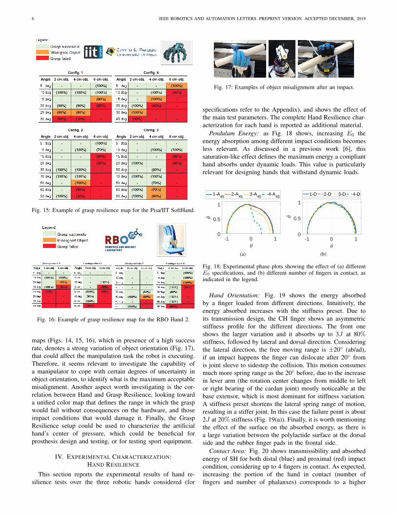
Hand/Load Orientation: the effect of the hand/load orien-tation can be observed in Fig. 11, where to each configurationcorresponds a different value of W and Tr. Moreover, the colormaps (Figs. 15-16) provide an overview of the grasp successrate under a specific load for each hand/load configuration andpendulum initial energy (release angle).
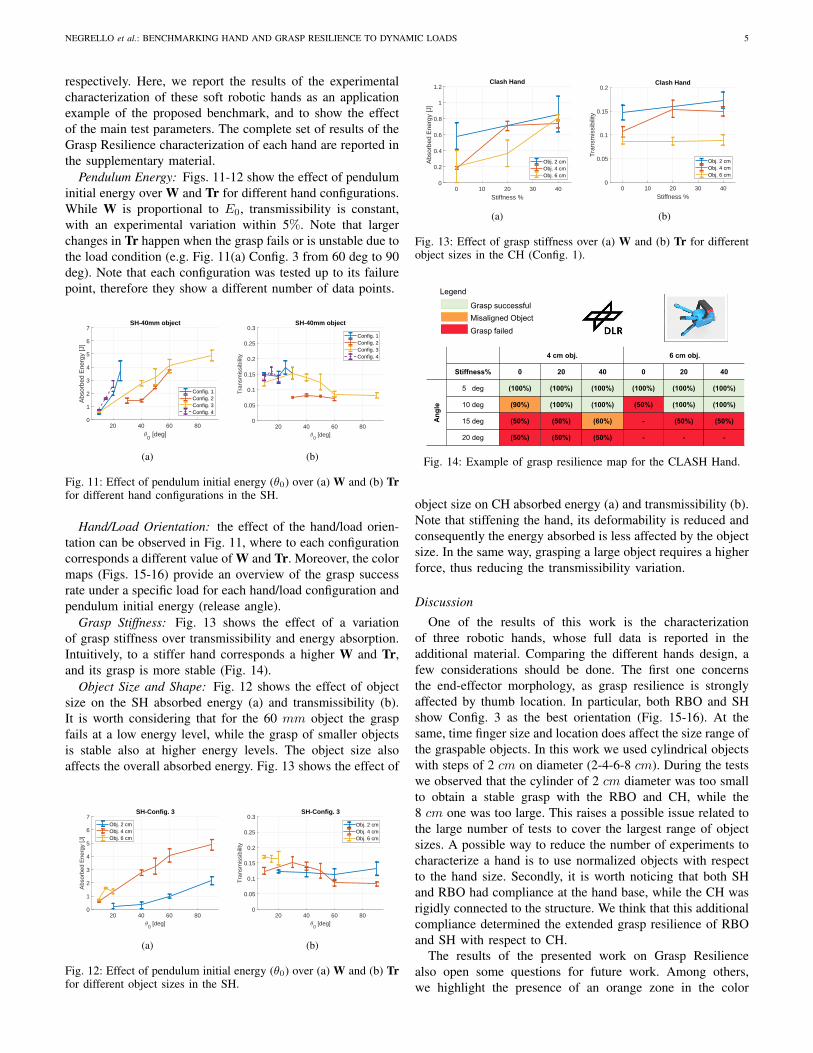
Grasp Stiffness: Fig. 13 shows the effect of a variationof grasp stiffness over transmissibility and energy absorption.Intuitively, to a stiffer hand corresponds a higher W and Tr,and its grasp is more stable (Fig. 14).
Object Size and Shape: Fig. 12 shows the effect of objectsize on the SH absorbed energy (a) and transmissibility (b).It is worth considering that for the 60 mm object the graspfails at a low energy level, while the grasp of smaller objectsis stable also at higher energy levels. The object size alsoaffects the overall absorbed energy. Fig. 13 shows the effect of
20 40 60 80
0 [deg]
0
1
2
3
4
5
6
7
Abs
orbe
d E
nerg
y [J
]
SH-Config. 3
Obj. 2 cmObj. 4 cmObj. 6 cm
(a)
20 40 60 80
0 [deg]
0
0.05
0.1
0.15
0.2
0.25
0.3
Tra
nsm
issi
bilit
y
SH-Config. 3
Obj. 2 cmObj. 4 cmObj. 6 cm
(b)
Fig. 12: Effect of pendulum initial energy (θ0) over (a) W and (b) Trfor different object sizes in the SH.
0 10 20 30 40
Stiffness %
0
0.2
0.4
0.6
0.8
1
1.2
Abs
orbe
d E
nerg
y [J
]
Clash Hand
Obj. 2 cmObj. 4 cmObj. 6 cm
(a)
0 10 20 30 40
Stiffness %
0
0.05
0.1
0.15
0.2
Tra
nsm
issi
bilit
y
Clash Hand
Obj. 2 cmObj. 4 cmObj. 6 cm
(b)
Fig. 13: Effect of grasp stiffness over (a) W and (b) Tr for differentobject sizes in the CH (Config. 1).
4 cm obj. 6 cm obj.
Stiffness% 0 20 40 0 20 40
An
gle
5 deg (100%) (100%) (100%) (100%) (100%) (100%)
10 deg (90%) (100%) (100%) (50%) (100%) (100%)
15 deg (50%) (50%) (60%) - (50%) (50%)
20 deg (50%) (50%) (50%) - - -
Legend
Grasp successful
Misaligned Object
Grasp failed
Fig. 14: Example of grasp resilience map for the CLASH Hand.
object size on CH absorbed energy (a) and transmissibility (b).Note that stiffening the hand, its deformability is reduced andconsequently the energy absorbed is less affected by the objectsize. In the same way, grasping a large object requires a higherforce, thus reducing the transmissibility variation.
Discussion
One of the results of this work is the characterizationof three robotic hands, whose full data is reported in theadditional material. Comparing the different hands design, afew considerations should be done. The first one concernsthe end-effector morphology, as grasp resilience is stronglyaffected by thumb location. In particular, both RBO and SHshow Config. 3 as the best orientation (Fig. 15-16). At thesame, time finger size and location does affect the size range ofthe graspable objects. In this work we used cylindrical objectswith steps of 2 cm on diameter (2-4-6-8 cm). During the testswe observed that the cylinder of 2 cm diameter was too smallto obtain a stable grasp with the RBO and CH, while the8 cm one was too large. This raises a possible issue related tothe large number of tests to cover the largest range of objectsizes. A possible way to reduce the number of experiments tocharacterize a hand is to use normalized objects with respectto the hand size. Secondly, it is worth noticing that both SHand RBO had compliance at the hand base, while the CH wasrigidly connected to the structure. We think that this additionalcompliance determined the extended grasp resilience of RBOand SH with respect to CH.
The results of the presented work on Grasp Resiliencealso open some questions for future work. Among others,we highlight the presence of an orange zone in the color
6 IEEE ROBOTICS AND AUTOMATION LETTERS. PREPRINT VERSION. ACCEPTED DECEMBER, 2019
Fig. 15: Example of grasp resilience map for the Pisa/IIT SoftHand.
Fig. 16: Example of grasp resilience map for the RBO Hand 2.
maps (Figs. 14, 15, 16), which in presence of a high successrate, denotes a strong variation of object orientation (Fig. 17),that could affect the manipulation task the robot is executing.Therefore, it seems relevant to investigate the capability ofa manipulator to cope with certain degrees of uncertainty inobject orientation, to identify what is the maximum acceptablemisalignment. Another aspect worth investigating is the cor-relation between Hand and Grasp Resilience, looking towarda unified color map that defines the range in which the graspwould fail without consequences on the hardware, and thoseimpact conditions that would damage it. Finally, the GraspResilience setup could be used to characterize the artificialhand’s center of pressure, which could be beneficial forprosthesis design and testing, or for testing sport equipment.
IV. EXPERIMENTAL CHARACTERIZATION:HAND RESILIENCE
This section reports the experimental results of hand re-silience tests over the three robotic hands considered (for
Fig. 17: Examples of object misalignment after an impact.
specifications refer to the Appendix), and shows the effect ofthe main test parameters. The complete Hand Resilience char-acterization for each hand is reported as additional material.
Pendulum Energy: as Fig. 18 shows, increasing E0 theenergy absorption among different impact conditions becomesless relevant. As discussed in a previous work [6], thissaturation-like effect defines the maximum energy a complianthand absorbs under dynamic loads. This value is particularlyrelevant for designing hands that withstand dynamic loads.
-1 0 10
0.5
1
1-A45
2-A45
3-A45
4-A45
(a)
-1 0 10
0.5
1
1-D 2-D 3-D 4-D
(b)
Fig. 18: Experimental phase plots showing the effect of (a) differentE0 specifications, and (b) different number of fingers in contact, asindicated in the legend.
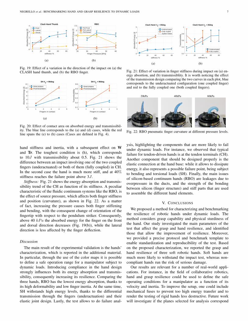
Hand Orientation: Fig. 19 shows the energy absorbedby a finger loaded from different directions. Intuitively, theenergy absorbed increases with the stiffness preset. Due toits transmission design, the CH finger shows an asymmetricstiffness profile for the different directions. The front oneshows the larger variation and it absorbs up to 3J at 80%stiffness, followed by lateral and dorsal direction. Consideringthe lateral direction, the free moving range is ±20◦ (ab/ad),if an impact happens the finger can dislocate after 20◦ fromis joint sleeve to sidestep the collision. This motion consumesmuch more spring range as the 20◦ before, due to the increasein lever arm (the rotation center changes from middle to leftor right bearing of the cardan joint) mostly noticeable at thebase extensor, which is most dominant for stiffness variation.A stiffness preset shortens the lateral spring range of motion,resulting in a stiffer joint. In this case the failure point is about2J at 20% stiffness (Fig. 19(a)). Finally, it is worth mentioningthe effect of the surface on the absorbed energy, as there isa large variation between the polylactide surface at the dorsalside and the rubber finger pads in the frontal side.
Contact Area: Fig. 20 shows transmissibility and absorbedenergy of SH for both distal (blue) and proximal (red) impactcondition, considering up to 4 fingers in contact. As expected,increasing the portion of the hand in contact (number offingers and number of phalanxes) corresponds to a higher
NEGRELLO et al.: BENCHMARKING HAND AND GRASP RESILIENCE TO DYNAMIC LOADS 7
0 20 40 60 80
stiffness %
0
1
2
3
4A
bsor
bed
Ene
rgy
[J]
Clash Hand Thumb
FrontLateralDorsal
(a)
20 30 40 50 60
Finger Pressure [kPa]
0
0.5
1
1.5
2
2.5
Abs
orbe
d E
nerg
y [J
]
RBO
P10 FrontP10 LateralP10 Dorsal
(b)
Fig. 19: Effect of a variation in the direction of the impact on (a) theCLASH hand thumb, and (b) the RBO finger.
0 1 2 3 4 5
Fingers in contact
0
2
4
6
8
10
12
Abs
orbe
d E
nerg
y [J
]
SH 0 = 90deg
Distal phalanxProximal phalanx
(a)
0 1 2 3 4 5
Fingers in contact
0.1
0.2
0.3
0.4
0.5
0.6
Tra
nsm
issi
bilit
y
SH 0 = 90deg
Distal phalanxProximal phalanx
(b)
Fig. 20: Effect of contact area on absorbed energy and transmissibil-ity. The blue line corresponds to the (a) and (d) cases, while the redline spans the (e) to (h) cases (Cases are defined in Fig. 4).
hand stiffness and inertia, with a subsequent effect on Wand Tr. The toughest condition is (h), which correspondsto 10J with transmissibility about 0.5. Fig. 21 shows thedifference between an impact involving one of the two coupledfingers (underactuated) or both of them (fully coupled) in CH.In the second case the hand is much more stiff, and at 40%stiffness reaches the failure point above 3J .
Stiffness: Fig. 21 shows the energy absorption and transmis-sibility trend of the CH as function of its stiffness. A peculiarcharacteristic of the fluidic continuum systems like the RBO, isthe effect of source pressure, which affects both finger stiffnessand position (curvature), as shown in Fig. 22. As a matterof fact, increasing the pressure causes both finger stiffeningand bending, with the consequent change of orientation of thefingertip with respect to the pendulum striker. Consequently,above 40 kPa the absorbed energy for the finger on the frontand dorsal direction decreases (Fig. 19(b)), while the lateraldirection is less affected by the finger deflection.
Discussion
The main result of the experimental validation is the hands’characterization, which is reported in the additional material.In particular, through the use of the color maps it is possibleto define a safe operation range for a manipulator subject todynamic loads. Introducing compliance in the hand designstrongly influences both its energy absorption and transmis-sibility, consequently increasing its resilience. Comparing thethree hands, RBO has the lowest energy absorption, thanks toits high deformability and low finger inertia. At the same time,SH withstands high energy levels, thanks to the differentialtransmission through the fingers (underactuation) and theirelastic joint design. Lastly, the test allows to do failure anal-
0 20 40 60 80
stiffness %
0
1
2
3
4
5
Abs
orbe
d E
nerg
y [J
]
Clash Hand 0 = 30deg
UnderactuatedFully coupledSystem Failure
(a)
0 20 40 60 80
stiffness %
0.2
0.4
0.6
0.8
1
Tra
nsm
issi
bilit
y
Clash Hand 0 = 30deg
UnderactuatedFully coupled
(b)
Fig. 21: Effect of variation in finger stiffness during impact on (a) en-ergy absortion, and (b) transmissiblity. It is worth noticing the effectof the transmission design comparing the two curves in each plot, bluecorresponds to the underactuated configuration (one coupled finger)and red to the fully coupled one (both coupled fingers).
20kPa 40kPa 60kPa
Fig. 22: RBO pneumatic finger curvature at different pressure levels.
ysis, highlighting the components that are more likely to failunder dynamic loads. For instance, we observed that typicalfailure for tendon-driven hands is at the tendon terminals (CH).Another component that should be designed properly is theelastic connection at the hand base: while it allows to dissipateenergy, it also represents a possible failure point, being subjectto bending and torsional loads (SH). Finally, the main issuesof silicon-based continuum hands (RBO) are leakages due tooverpressure in the ducts, and the strength of the bondingbetween silicon (finger structure) and stiff parts that are usedto assemble the different hand elements.
V. CONCLUSIONS
We proposed a method for characterizing and benchmarkingthe resilience of robotic hands under dynamic loads. Themethod considers grasp capability and physical sturdiness ofthe hand. Our study investigated the main parameters of thetest that affect the grasp and hand resilience, and identifiedthose that allow the improvement of resilience. Moreover,we provided a precise protocol and benchmark template toenable standardization and reproducibility of the test. Basedon the proposed characterization, we reported the grasp andhand resilience of three soft robotic hands. Soft hands aremuch more likely to withstand the impact test, whereas non-compliant hands run the risk of serious damage.
Our results are relevant for a number of real-world appli-cations. For instance, in the field of collaborative robotics,hand and grasp resilience could be used to define the safeoperating conditions for a manipulator as a function of itsvelocity and inertia. To improve the setup, one could includemechanical fuses to prevent too high energy transfer and torender the testing of rigid hands less destructive. Future workwill investigate if the planes selected for analysis correspond
8 IEEE ROBOTICS AND AUTOMATION LETTERS. PREPRINT VERSION. ACCEPTED DECEMBER, 2019
(a) (b) (c)
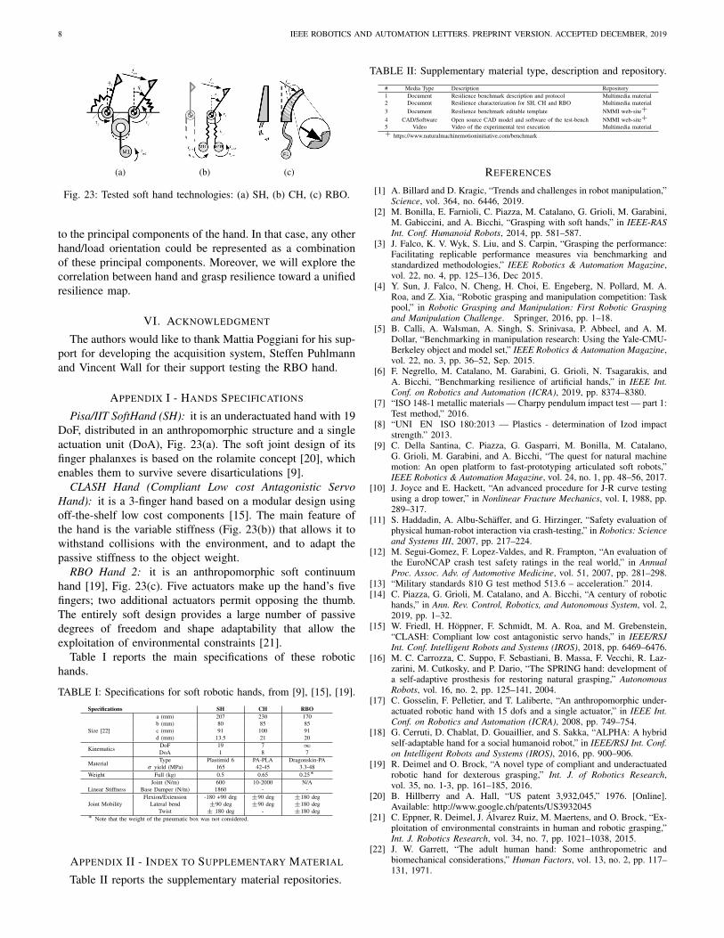
Fig. 23: Tested soft hand technologies: (a) SH, (b) CH, (c) RBO.
to the principal components of the hand. In that case, any otherhand/load orientation could be represented as a combinationof these principal components. Moreover, we will explore thecorrelation between hand and grasp resilience toward a unifiedresilience map.
VI. ACKNOWLEDGMENT
The authors would like to thank Mattia Poggiani for his sup-port for developing the acquisition system, Steffen Puhlmannand Vincent Wall for their support testing the RBO hand.
APPENDIX I - HANDS SPECIFICATIONS
Pisa/IIT SoftHand (SH): it is an underactuated hand with 19DoF, distributed in an anthropomorphic structure and a singleactuation unit (DoA), Fig. 23(a). The soft joint design of itsfinger phalanxes is based on the rolamite concept [20], whichenables them to survive severe disarticulations [9].
CLASH Hand (Compliant Low cost Antagonistic ServoHand): it is a 3-finger hand based on a modular design usingoff-the-shelf low cost components [15]. The main feature ofthe hand is the variable stiffness (Fig. 23(b)) that allows it towithstand collisions with the environment, and to adapt thepassive stiffness to the object weight.
RBO Hand 2: it is an anthropomorphic soft continuumhand [19], Fig. 23(c). Five actuators make up the hand’s fivefingers; two additional actuators permit opposing the thumb.The entirely soft design provides a large number of passivedegrees of freedom and shape adaptability that allow theexploitation of environmental constraints [21].
Table I reports the main specifications of these robotichands.
TABLE I: Specifications for soft robotic hands, from [9], [15], [19].Specifications SH CH RBO
Size [22]
a (mm) 207 230 170b (mm) 80 85 85c (mm) 91 100 91d (mm) 13.5 21 20
Kinematics DoF 19 7 ∞DoA 1 8 7
Material Type Plastimid 6 PA-PLA Dragonskin-PAσ yield (MPa) 165 42-45 3.3-48
Weight Full (kg) 0.5 0.65 0.25∗
Linear StiffnessJoint (N/m) 600 10-2000 N/A
Base Damper (N/m) 1860 - -
Joint MobilityFlexion/Extension -180 +90 deg ±90 deg ±180 deg
Lateral bend ±90 deg ±90 deg ±180 degTwist ± 180 deg - ±180 deg
∗ Note that the weight of the pneumatic box was not considered.
APPENDIX II - INDEX TO SUPPLEMENTARY MATERIAL
Table II reports the supplementary material repositories.
TABLE II: Supplementary material type, description and repository.
# Media Type Description Repository1 Document Resilience benchmark description and protocol Multimedia material2 Document Resilience characterization for SH, CH and RBO Multimedia material3 Document Resilience benchmark editable template NMMI web-site+
4 CAD/Software Open source CAD model and software of the test-bench NMMI web-site+
5 Video Video of the experimental test execution Multimedia material+ https://www.naturalmachinemotioninitiative.com/benchmark
REFERENCES
[1] A. Billard and D. Kragic, “Trends and challenges in robot manipulation,”Science, vol. 364, no. 6446, 2019.
[2] M. Bonilla, E. Farnioli, C. Piazza, M. Catalano, G. Grioli, M. Garabini,M. Gabiccini, and A. Bicchi, “Grasping with soft hands,” in IEEE-RASInt. Conf. Humanoid Robots, 2014, pp. 581–587.
[3] J. Falco, K. V. Wyk, S. Liu, and S. Carpin, “Grasping the performance:Facilitating replicable performance measures via benchmarking andstandardized methodologies,” IEEE Robotics & Automation Magazine,vol. 22, no. 4, pp. 125–136, Dec 2015.
[4] Y. Sun, J. Falco, N. Cheng, H. Choi, E. Engeberg, N. Pollard, M. A.Roa, and Z. Xia, “Robotic grasping and manipulation competition: Taskpool,” in Robotic Grasping and Manipulation: First Robotic Graspingand Manipulation Challenge. Springer, 2016, pp. 1–18.
[5] B. Calli, A. Walsman, A. Singh, S. Srinivasa, P. Abbeel, and A. M.Dollar, “Benchmarking in manipulation research: Using the Yale-CMU-Berkeley object and model set,” IEEE Robotics & Automation Magazine,vol. 22, no. 3, pp. 36–52, Sep. 2015.
[6] F. Negrello, M. Catalano, M. Garabini, G. Grioli, N. Tsagarakis, andA. Bicchi, “Benchmarking resilience of artificial hands,” in IEEE Int.Conf. on Robotics and Automation (ICRA), 2019, pp. 8374–8380.
[7] “ISO 148-1 metallic materials — Charpy pendulum impact test — part 1:Test method,” 2016.
[8] “UNI EN ISO 180:2013 — Plastics - determination of Izod impactstrength.” 2013.
[9] C. Della Santina, C. Piazza, G. Gasparri, M. Bonilla, M. Catalano,G. Grioli, M. Garabini, and A. Bicchi, “The quest for natural machinemotion: An open platform to fast-prototyping articulated soft robots,”IEEE Robotics & Automation Magazine, vol. 24, no. 1, pp. 48–56, 2017.
[10] J. Joyce and E. Hackett, “An advanced procedure for J-R curve testingusing a drop tower,” in Nonlinear Fracture Mechanics, vol. I, 1988, pp.289–317.
[11] S. Haddadin, A. Albu-Schaffer, and G. Hirzinger, “Safety evaluation ofphysical human-robot interaction via crash-testing,” in Robotics: Scienceand Systems III, 2007, pp. 217–224.
[12] M. Segui-Gomez, F. Lopez-Valdes, and R. Frampton, “An evaluation ofthe EuroNCAP crash test safety ratings in the real world,” in AnnualProc. Assoc. Adv. of Automotive Medicine, vol. 51, 2007, pp. 281–298.
[13] “Military standards 810 G test method 513.6 – acceleration.” 2014.[14] C. Piazza, G. Grioli, M. Catalano, and A. Bicchi, “A century of robotic
hands,” in Ann. Rev. Control, Robotics, and Autonomous System, vol. 2,2019, pp. 1–32.
[15] W. Friedl, H. Hoppner, F. Schmidt, M. A. Roa, and M. Grebenstein,“CLASH: Compliant low cost antagonistic servo hands,” in IEEE/RSJInt. Conf. Intelligent Robots and Systems (IROS), 2018, pp. 6469–6476.
[16] M. C. Carrozza, C. Suppo, F. Sebastiani, B. Massa, F. Vecchi, R. Laz-zarini, M. Cutkosky, and P. Dario, “The SPRING hand: development ofa self-adaptive prosthesis for restoring natural grasping,” AutonomousRobots, vol. 16, no. 2, pp. 125–141, 2004.
[17] C. Gosselin, F. Pelletier, and T. Laliberte, “An anthropomorphic under-actuated robotic hand with 15 dofs and a single actuator,” in IEEE Int.Conf. on Robotics and Automation (ICRA), 2008, pp. 749–754.
[18] G. Cerruti, D. Chablat, D. Gouaillier, and S. Sakka, “ALPHA: A hybridself-adaptable hand for a social humanoid robot,” in IEEE/RSJ Int. Conf.on Intelligent Robots and Systems (IROS), 2016, pp. 900–906.
[19] R. Deimel and O. Brock, “A novel type of compliant and underactuatedrobotic hand for dexterous grasping,” Int. J. of Robotics Research,vol. 35, no. 1-3, pp. 161–185, 2016.
[20] B. Hillberry and A. Hall, “US patent 3,932,045,” 1976. [Online].Available: http://www.google.ch/patents/US3932045
[21] C. Eppner, R. Deimel, J. Alvarez Ruiz, M. Maertens, and O. Brock, “Ex-ploitation of environmental constraints in human and robotic grasping,”Int. J. Robotics Research, vol. 34, no. 7, pp. 1021–1038, 2015.
[22] J. W. Garrett, “The adult human hand: Some anthropometric andbiomechanical considerations,” Human Factors, vol. 13, no. 2, pp. 117–131, 1971.