benchmarking problems in fatigue crack growth … · benchmarking problems in fatigue crack growth...
TRANSCRIPT

Benchmarking Problems in Fatigue
Crack Growth Analyses
Robert PilarczykPrincipal Engineer, Hill Engineering, LLC
Caleb MorrisonMechanical Engineer, Hill Engineering, LLC
Josh HodgesT-38 Structural Integrity Analyst, USAF
AFGROW Workshop 2016
September 14, 2016

© 2016 Hill Engineering, LLC
hill-engineering.com2
Overview/Outline
Overview of Software Programs and Features
BAMF
BEASY
FRANC3D
Benchmark Cases
Overview
Approach
Comparison Goals
Discussion of Results
Future Plans
© 2016 Hill Engineering, LLC
hill-engineering.com3
BAMF Features
Broad Application for Modeling Failure (BAMF)
Overview:
USAF organically developed plug-in coupling FEA stress intensity calculations
(StressCheck) with crack growth engine (AFGROW)
StressCheck
• P-element finite element code
Key Features:
2-D planar growth
Full suite of AFGROW capabilities
• Materials, spectra, retardation, etc.
Multiple crack front support
Surface based application of crack face traction
Current Limitations:
Planar growth

© 2016 Hill Engineering, LLC
hill-engineering.com4
BEASY Features
Overview:
COTS software with integrated Boundary Element code and crack growth engine
Key Features:
3D non-planar growth
Load spectrum support
NASGRO library support
Tabulated material data support
Retardation Models (GW and MGW)
Multiple crack front support
Mesh based application of crack face traction
Current Limitations
Symmetry at crack face

© 2016 Hill Engineering, LLC
hill-engineering.com5
FRANC3D Features
Overview COTS software with integrated Finite Element code (previously boundary element)
and crack growth engine• H-element FE code
Key Features: Mesh based application of crack face traction
3D non-planar growth
Load spectrum support
NASGRO library support
Tabulated material data support
GW Retardation Model
Crack front smoothing/fitting
Multiple crack front support
Python API for automation
Global/Local mesh segregation
Use of symmetry BCs
Current Limitation: MGW Retardation Model

© 2016 Hill Engineering, LLC
hill-engineering.com6
Evaluation Plan
General approach
Define benchmark problems
Slowly increase the complexity of the problems
• Allowed for basic validation of the software (e.g., handbook solutions)
• Created a gradual learning curve for the software itself
• Made identification of problematic analysis components easy since they are added
piecemeal
Compared to complicated scenarios typically encountered with this type of
analysis, the test cases remain quite simple. However, these relatively simple
cases test a wide range of functionality in ways that allowed for easy
comparisons.

© 2016 Hill Engineering, LLC
hill-engineering.com7
Evaluation Test Matrix
Test ID NASGRO ID Geometry Analysis Goals
FT01 TC02 Edge Cracked PlateComparison of SIF values to benchmark for 3D and
2D (plane strain) cases
FT02 TC01 Center Cracked Plate
Comparison of SIF values to benchmark for 3D and
2D (plane strain) cases and use of symmetry BCs
(FRANC3D & BAMF only).
FT03 TC01 Center Cracked PlateUse of NASGRO material model in a crack growth
simulation with constant amplitude loading.
FT04 CC01 Corner Cracked PlateUse of tabular material data, localized remeshing,
and spectrum loading in a FCG simulation.
FT05 TC02 Edge Cracked PlateDemonstration of applying crack face traction
interpolated from an arbitrary mesh.

© 2016 Hill Engineering, LLC
hill-engineering.com8
FT01: Basic Overview
FT01 Demonstration Goals:
Duplication of benchmark case provided in FRANC3D documentation
Comparison of 3D and 2D plane strain SIF results
FT01/TC02 Geometry
Dimensions
h = 5
b = 5
a = 0.5
t = 5
Material: E = 3.0e7, ν = 0.30
Loading: Uniform unit stress

© 2016 Hill Engineering, LLC
hill-engineering.com9
FT01: Loading and Mesh
Geometry, loading, and boundary conditions are as shown belowFRANC3D
Initial mesh = 275 C3D20R Elements
BEASY
Initial mesh = 1122 S4R shell elements
StressCheck
Mesh = 9245 tetrahedral elements
Mesh = 1764 tetrahedral elements

© 2016 Hill Engineering, LLC
hill-engineering.com10
FT01: Crack Geometry: BEASY, FRANC3D
FRANC3D Crack Settings
Crack length was 0.5
Template radius was 0.05
Volume Meshing was done
with ABAQUS
Crack front template used 5
integration rings with 8
elements per ring.
FRANC3D Crack Mesh/Geometry
Beasy Crack Mesh
© 2016 Hill Engineering, LLC
hill-engineering.com11
FT01: Crack Geometry: StressCheck
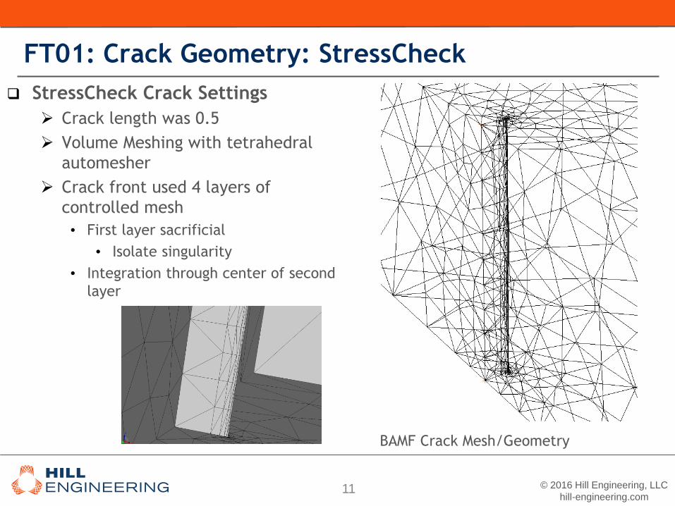
StressCheck Crack Settings
Crack length was 0.5
Volume Meshing with tetrahedral
automesher
Crack front used 4 layers of
controlled mesh
• First layer sacrificial
• Isolate singularity
• Integration through center of second
layer
BAMF Crack Mesh/Geometry

© 2016 Hill Engineering, LLC
hill-engineering.com12
FT01: FRANC3D SIF Results
Rings used for integrationNote that the first ring is
made up of wedge elements
with the remaining rings using
brick elements.
The volume is meshed using
tetrahedral elements.
Note: Deformations are scaled by 3e6

© 2016 Hill Engineering, LLC
hill-engineering.com13
FT01: StressCheck SIF Results
Rings used for integration

© 2016 Hill Engineering, LLC
hill-engineering.com14
FT01: K1 2D and 3D Handbook Comparison
Enforced Plane Strain – Max Error Relative to Handbook Solution:
-BEASY 0.48%
-FRANC3D 0.31%
-StressCheck 0.63%

© 2016 Hill Engineering, LLC
hill-engineering.com15
FT02: Basic Overview
FT02 Demonstration Goals:
Duplication of benchmark case provided in FRANC3D documentation
Comparison of 3D and 2D plane strain SIF results
Use of symmetry boundary conditions in StressCheck and FRANC3D for mesh size
reduction (a feature BEASY doesn’t support)
FT02/TC01 Geometry
Dimensions
h = 5
b = 5
a = 0.5
t = 5
Material: E = 3.0e7, ν = 0.30
Loading: Uniform unit stress

© 2016 Hill Engineering, LLC
hill-engineering.com16
FT02: Loading and Mesh
Geometry, loading, and boundary conditions are as shown belowFRANC3D BEASY
StressCheck

© 2016 Hill Engineering, LLC
hill-engineering.com17
FT02: K1 2D and 3D Handbook Comparison
Enforced Plane Strain – Max Error
Relative to Handbook Solution:
-BEASY 0.41%
-FRANC3D 0.61%
-StressCheck 0.54%

© 2016 Hill Engineering, LLC
hill-engineering.com18
FT03: Basic Overview
FT03 Demonstration Goals:
Crack growth under constant amplitude (R = 0 ) loading
Basic use of NASGRO materials
Comparison and validation of SIF results with a handbook solution
Comparison and validation of lifing results with NASGRO TC01
FT03/TC01 Geometry
Dimensions (in)
h = 2
b = 1
a = 0.05
t = 0.125
Material: 7075-T651 (11AB1)
Loading: 24 ksi (R = 0)

© 2016 Hill Engineering, LLC
hill-engineering.com19
FT03: FRANC3D Geometry, Loading, and Mesh
ABAQUS Geometry and Loading
MeshGlobal Mesh
FRANC3D Remeshing Region
X Symmetry Plane
Plane of U2 = 0
Global U3 = 0 (plane strain)
U1 = 0
σ= 24 ksi Element Type is C3D20R
105 elements in total
Symmetry is used to reduce model size and runtime
Mesh is split into two regions: A global region that remains unchanged during the simulation and a local region that FRANC3D remeshing for each crack growth step

© 2016 Hill Engineering, LLC
hill-engineering.com20
FT03: BAMF Geometry, Loading, and Mesh
X Symmetry Plane
Plane Fixed in Y
Forward and Back
Face Fixed in Z
σ= 24 ksi

© 2016 Hill Engineering, LLC
hill-engineering.com21
FT03: FRANC3D Crack Geometry
Initial Crack Geometry: a = 0.05 in Final Crack Geometry: a = 0.327 in
After 56 steps, the crack front remains undistorted thanks
in part to crack front smoothing (as shown below).
Template Radius: 0.0025
Number of Rings: 3
Elements per Ring: 8

© 2016 Hill Engineering, LLC
hill-engineering.com22
FT03: BAMF Crack Geometry
Initial Crack Geometry: a = 0.05 in Final Crack Geometry: a = 0.297 in
Layers of Mesh Refinement: 2

© 2016 Hill Engineering, LLC
hill-engineering.com23
FT03: Note on Smoothing
Crack Front Smoothing
FRANC3D smooths crack front
BEASY smooths SIF values
BAMF smooths crack front and
SIF values

© 2016 Hill Engineering, LLC
hill-engineering.com24
FT03: Example Stress and Displacement Results
FRANC3D BAMF

© 2016 Hill Engineering, LLC
hill-engineering.com25
FT03: Paris Law Crack Life Results
FRANC3D uses NASGRO 5 equation
NASGRO results are from NASGRO
7.10
All predictions, with the exception of
BAMF, return nearly the exact same
crack growth curve when using the
Paris law growth model
BAMF prediction ~ 102%
𝐶0 = 1.51 × 10⁻⁹𝑖𝑛
𝑐𝑦𝑐𝑙𝑒𝑠
𝑘𝑠𝑖 𝑖𝑛𝑚
m = 3.70
Cth = 0
KIC = 26 ksi√𝑖𝑛

© 2016 Hill Engineering, LLC
hill-engineering.com26
FT03: KI Comparison
All analyses enforced plane strain
FRANC3D maximum SIF deviation = 0.55%
BAMF maximum SIF deviation = 0.64%
BEASY maximum SIF deviation = 0.69%
Handbook solution is TC01 (ASTM E647): 𝐾1 = sec𝜋𝑎
2𝑏𝜎 𝜋𝑎

© 2016 Hill Engineering, LLC
hill-engineering.com27
FT03: NASGRO Equation Crack Life Results
FRANC3D, NASGRO,
AFGROW, and BAMF are in
excellent agreement
BEASY’s SIF values lifed in
NASGRO give results similar
to other predictions

© 2016 Hill Engineering, LLC
hill-engineering.com28
FT04: Basic Overview
FT04 Demonstration Goals:
Localized re-meshing
Variable amplitude loading with both compressive and tensile loads
Tabular material data
Comparison and validation of FRANC3D lifing results with NASGRO CC01
FT06/CC01 Geometry
Dimensions (in)
h = 9
b = 4
t = 6
a = 0.05
Material: Tabulated 7050 (M7GQ11AB1)
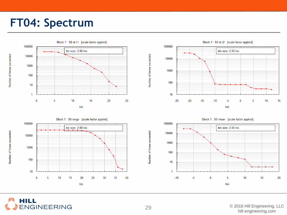
Loading: Variable with 𝑆𝑚𝑎𝑥 = 24 ksi
© 2016 Hill Engineering, LLC
hill-engineering.com29
FT04: Spectrum

© 2016 Hill Engineering, LLC
hill-engineering.com30
FT04: Crack Growth Results

© 2016 Hill Engineering, LLC
hill-engineering.com31
FT04: KI Results
KI values at surface
BEASY, FRANC3D, AFGROW, and
BAMF give KI values consistently higher
than NASGRO.

© 2016 Hill Engineering, LLC
hill-engineering.com32
FT05: Basic Overview
FT05 Demonstration Goals:
Far field vs. crack face traction
Should result in same SIF
FT05/TC01 Geometry
Dimensions
h = 0.75
b = 1.25
a = 0.25
t = 0.125
Material: E = 10.4 ksi, ν = 0.33
Loading: 17 ksi tensile load

© 2016 Hill Engineering, LLC
hill-engineering.com33
FT05: Mesh and Load
Baseline Case:
The model/mesh shown to the right was subject to a 17 ksi tensile load
The SIF results for KI were calculated
StressCheck requires crack face traction to be input as formulae

© 2016 Hill Engineering, LLC
hill-engineering.com34
FT05: KI Results
FRANC 3D KI values are practically identical
StressCheck K1 values differ by as much as 2.3%

© 2016 Hill Engineering, LLC
hill-engineering.com35
Summary
Multiple Benchmarks Completed between Three Different Software
Suites
BAMF – StressCheck P-element based Finite Element, AFGROW
BEASY - Boundary Element, Internal Crack Growth
FRANC3D – H-element based Finite Element, Internal Crack Growth
Stress Intensity Comparisons to Handbook Solutions Demonstrated
Accuracy within ~0.5%
Different Methods are Employed to Smooth Crack Front and/or Stress
Intensities
Overall, Consistent Crack Growth Predictions are Observed with Some
Noted Differences
Far Field vs. Crack Face Traction Comparisons were Completed with
Mixed Results

© 2016 Hill Engineering, LLC
hill-engineering.com36
Future Plans
Investigate Differences Noted in Benchmark Cases Completed
Engage in discussions with focals for each software suite
Additional Benchmarks:
Open Hole in a Plate (non-coldworked)
Open Hole in a Plate (coldworked)
Complex Geometry
Complex Geometry with Residual Stress
Compare:
Life Prediction
Crack Shape Evolution
Additional Features:
• Retardation
• Complex loading
• Multiple crack fronts

© 2016 Hill Engineering, LLC
hill-engineering.com37
Future Plans

© 2016 Hill Engineering, LLC
hill-engineering.com38
Future Plans

© 2016 Hill Engineering, LLC
hill-engineering.com39
Questions?
Caleb MorrisonMechanical Engineer, Hill Engineering, LLC
Phone: 916-635-5706
Josh HodgesT-38 Structural Integrity Analyst, USAF
Phone: 801-777-4613
Robert PilarczykPrincipal Engineer, Hill Engineering, LLC
Phone: 801-391-2682