bending stresses & shear stresses in beams ... · pdf filebending stresses & shear...
TRANSCRIPT

BENDING STRESSES & SHEAR STRESSES IN BEAMS
(ASSIGNMENT SOLUTIONS)
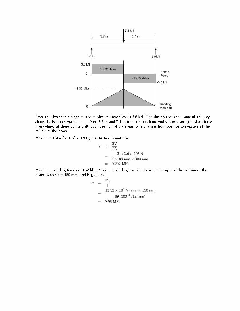
Question 1: A 89 mm×300 mm Parallam beam has a length of 7.4 m and supports a concentrated load of7.2 kN, as illustrated below. Draw shear force and bending moment diagrams for the beam. Find themaximum maximum shear stress and the maximum bending stress.
7.2 kN
3.7 m 3.7 m
Solution:
The beam is symmetrical about its mid-point, so the reactions are equal:
RA = RB =7.2
2= 3.6 kN
The load and reactions are concentrated forces so the shear forces are constant between the concentratedloads. For example, take any section through the beam at 0 < x < 3.7 m from the left end of the beam andexamine the vertical forces:
ΣFy = 3.6− V
= 0
V = 3.6 kN
A similar calculation for any section through the beam at 3.7 < x < 7.4 m yields:
ΣFy = 3.6− 7.2− V
= 0
V = −3.6 kN
The bending moment diagrams for concentrated forces are linear; that is, they have constant slope (they areof the form y = mx + c where m is the slope). These are most easily derived from the area under the shearforce diagram. The area under the shear force diagram to the left of x = 0 is 0 so the point (0,0) is on thebending moment diagram. The area under the shear force diagram immediately left of x = 3.7 m is3.6× 3.7 = 13.32 kN ·m so the point (3.7,13.32) is on the bending moment diagram. The straight linebetween these points represents the bending moments for the left half of the beam. A similar procedureprovides the line for the right hand side.
Note: There should not be any discontinuities (breaks) in the bending moment diagram. In the case of asimply supported beam in equilibrium, the bending moment should be 0 at the left hand side of the beamand return to 0 at the right hand side of the beam. This argument does not hold for cantilevers - seeQuestion 3 below.
7.2 kN
ShearForce
BendingMoments
0
3.6 kN
-3.6 kN
0
13.32 kN.m
-13.32 kN.m
13.32 kN.m
3.7 m 3.7 m
3.6 kN 3.6 kN
From the shear force diagram, the maximum shear force is 3.6 kN. The shear force is the same all the wayalong the beam except at points 0 m, 3.7 m and 7.4 m from the left hand end of the beam (the shear forceis unde�ned at these points), although the sign of the shear force changes from positive to negative at themiddle of the beam.
Maximum shear force of a rectangular section is given by:
τ =3V
2A
=3× 3.6× 103 N
2× 89 mm× 300 mm= 0.202 MPa
Maximum bending force is 13.32 kN. Maximum bending stresses occur at the top and the bottom of thebeam, where c = 150 mm, and is given by:
σ =Mc
I
=13.32× 10⁶ N ·mm× 150 mm
89 (300)3 /12 mm4
= 9.98 MPa
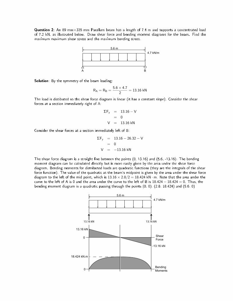
Question 2: An 89 mm×335 mm Parallam beam has a length of 7.4 m and supports a concentrated loadof 7.2 kN, as illustrated below. Draw shear force and bending moment diagrams for the beam. Find themaximum maximum shear stress and the maximum bending stress.
5.6 m
A B
4.7 kN/m
Solution: By the symmetry of the beam loading:
RA = RB =5.6× 4.7
2= 13.16 kN
The load is distibuted so the shear force diagram is linear (it has a constant slope). Consider the shearforces at a section immediately right of A:
ΣFy = 13.16− V
= 0
V = 13.16 kN
Consider the shear forces at a section immediately left of B:
ΣFy = 13.16− 26.32− V
= 0
V = −13.16 kN
The shear force diagram is a straight line between the points (0, 13.16) and (5.6, -13.16). The bendingmoment diagram can be calculated directly but is more easily given by the area under the shear forcediagram. Bending moments for distributed loads are quadratic functions (they are the integrals of the shearforce function). The value of the quadratic at the beam's midpoint is given by the area under the shear forcediagram to the left of the mid-point, which is 13.16× 2.8/2 = 18.424 kN ·m. Note that the area under thecurve to the left of A is 0 and the area under the curve to the left of B is 18.424− 18.424 = 0. Thus, thebending moment diagram is a quadratic passing through the points (0, 0), (2.8, 18.424) and (5.6, 0)
5.6 m
ShearForce
BendingMoments
0
13.16 kN
-13.16 kN
0
18.424 kN.m
4.7 kN/m
13.16 kN 13.16 kN
From the shear force diagram, the maximum shear force is 13.16 kN at both x = 0 m and at x = 5.6 m rightof A. Maximum shear force of a rectangular section is given by:
τ =3V
2A
=3× 13.16× 103 N
2× 89 mm× 335 mm= 0.662 MPa
The maximum bending moment is 18.424 kN ·m. Maximum bending stresses occur at the top and thebottom of the rectangular beam, where c = 335/2 = 167.5 mm, and is given by:
σ =Mc
I
=18.424× 10⁶ N ·mm× 167.5 mm
89 (335)3 /12 mm4
= 11.1 MPa
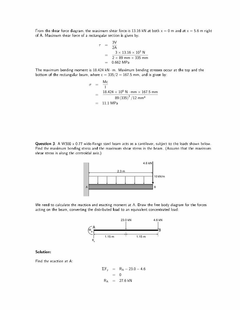
Question 3: A W300 x 0.77 wide-�ange steel beam acts as a cantilever, subject to the loads shown below.Find the maximum bending stress and the maximum shear stress in the beam. (Assume that the maximumshear stress is along the centroidal axis.)
2.3 m
4.6 kN
10 kN/m
A B
We need to calculate the reaction and reacting moment at A. Draw the free body diagram for the forcesacting on the beam, converting the distributed load to an equivalent concentrated load:
1.15 m
4.6 kN
AB
23.0 kN
Ma
RA
1.15 m
Solution:
Find the reaction at A:
ΣFy = RA − 23.0− 4.6
= 0
RA = 27.6 kN

Find the reacting moment at A:
ΣMA = Ma − 23.0× 1.15− 4.6× 2.3
= 0
Ma = 37.03 kN ·m
Now, use the method of sections to �nd the shear forces and bending moments between A and B. The loadsare distributed, so the shear force diagram is linear and the bending moment will be quadratic.
A
37.03 kN.m
27.6 kN
V M
Section right of A
A37.03 kN.m
27.6 kN
V M
Section left of B
23 kN1.15 m 1.15 m B
Consider a section immediately right of A. Draw the shear force, V, and the bending moment, M, in thepositive direction. Then:
ΣFy = 27.6− V
= 0
V = 27.6 kN
ΣMsection = M + 37.03
= 0
M = −37.03 kN ·m
Now repeat the procedure for a section immediately left of B:
ΣFy = 27.6− 23− V
= 0
V = 4.6 kN
ΣMsection = M + 37.03 + 23× 1.15− 27.6× 2.3
= 0
M = 0
The bending moment diagram is a quadratic that passes through (0, -37.03) and (2.3, 0). We need to �ndthe maximum value of the bending moment between these two points. How do we do that? How do we �ndthe equations of the bending moment diagram?
One method is to integrate the equation of the shear force diagram. The load along the beam between Aand B is uniformly distributed so the shear force diagram is a straight line between (0, 27.6) and (4, 4.6).The slope of this line is given by:
m =y1 − y0
x1 − x0
=4.6− 27.6
4− 0= −10
The equation of the line is y = mx + c = −10x + c and it passes through (0, 27.6). Solving for c, the curvebecomes y = −10x + 27.6. The equation of the bending moment diagram is the integral of this line:
M(x) =∫
(−10x + 27.6) dx
= −5x2 + 27.6x + c
= −5x2 + 27.6x− 37.03
(We found earlier that the bending moment immediately right of A is −37.02 kN ·m. This means thatM(0) = −37.03, so c = −37.03.)
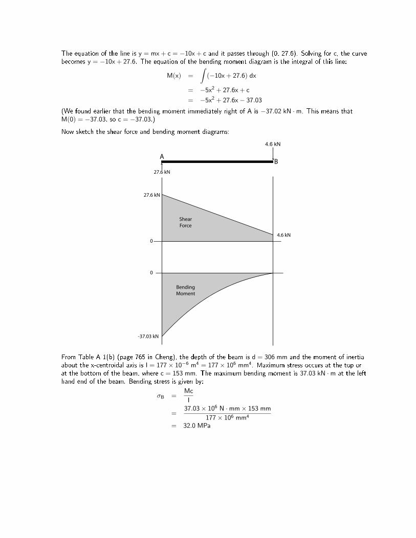
Now sketch the shear force and bending moment diagrams:
4.6 kN
AB
27.6 kN
27.6 kN
4.6 kN0
0
-37.03 kN
ShearForce
BendingMoment
From Table A-1(b) (page 765 in Cheng), the depth of the beam is d = 306 mm and the moment of inertiaabout the x-centroidal axis is I = 177× 10−6 m4 = 177× 106 mm4. Maximum stress occurs at the top orat the bottom of the beam, where c = 153 mm. The maximum bending moment is 37.03 kN ·m at the lefthand end of the beam. Bending stress is given by:
σB =Mc
I
=37.03× 10⁶ N ·mm× 153 mm
177× 106 mm4
= 32.0 MPa

Question 4: (Cheng 14-12 and Cheng 14-27) An inverted-T section beam is loaded as illustrated. Find themaximum tensile stress, maximum compressive stress and the maximum shear stress in the beam.
20 kN
B
40 kN1.0 m2.0 m2.0 m
200 mm
25 mm 150 mm
25 mm
A
Solution:
Calculate the reactions at A and at B:
ΣMA = −40× 2 + RB × 4− 20× 5
= 0
RB = 45 kN
ΣMB = −RA × 4 + 40× 2− 20× 1
= 0
RA = 15 kN
(Check) ΣFY = 15− 40 + 45− 20
= 0
Sketch the shear force and bending moment diagrams for the beam:
20 kN
C
40 kN1.0 m2.0 m2.0 m
A B
D15 kN 45 kN
15 kN
0
0
20 kN
-25 kN
30 kN.m
-20 kN.m
Shear Force
Bending Moment
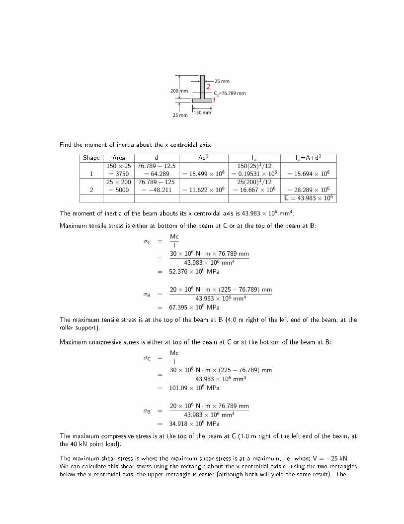
Find the x-centroidal axis of the beam (relative to the bottom of the beam):
y =A1y1 + A2y2
A1 + A2
=(150× 25) · 12.5 + (25× 200) · 125
(150× 25) + (25× 200)= 76.789 mm
200 mm
25 mm 150 mm
25 mm
CX=76.789 mm
1
2
Find the moment of inertia about the x-centroidal axis:
Shape Area d Ad2 Ix Ix=A+d2
150× 25 76.789− 12.5 150(25)3/121 = 3750 = 64.289 = 15.499× 106 = 0.19531× 106 = 15.694× 10⁶
25× 200 76.789− 125 25(200)3/122 = 5000 = −48.211 = 11.622× 106 = 16.667× 106 = 28.289× 10⁶
Σ = 43.983× 10⁶
The moment of inertia of the beam abouts its x-centroidal axis is 43.983× 106 mm4.
Maximum tensile stress is either at bottom of the beam at C or at the top of the beam at B:
σC =Mc
I
=30× 106 N ·m× 76.789 mm
43.983× 106 mm4
= 52.376× 10⁶ MPa
σB =20× 106 N ·m× (225− 76.789) mm
43.983× 106 mm4
= 67.395× 10⁶ MPa
The maximum tensile stress is at the top of the beam at B (4.0 m right of the left end of the beam, at theroller support).
Maximum compressive stress is either at top of the beam at C or at the bottom of the beam at B:
σC =Mc
I
=30× 106 N ·m× (225− 76.789) mm
43.983× 106 mm4
= 101.09× 10⁶ MPa
σB =20× 106 N ·m× 76.789 mm
43.983× 106 mm4
= 34.918× 10⁶ MPa
The maximum compressive stress is at the top of the beam at C (1.0 m right of the left end of the beam, atthe 40 kN point load).
The maximum shear stress is where the maximum shear stress is at a maximum, i.e. where V = −25 kN.We can calculate this shear stress using the rectangle about the x-centroidal axis or using the two rectanglesbelow the x-centroidal axis; the upper rectangle is easier (although both will yield the same result). The
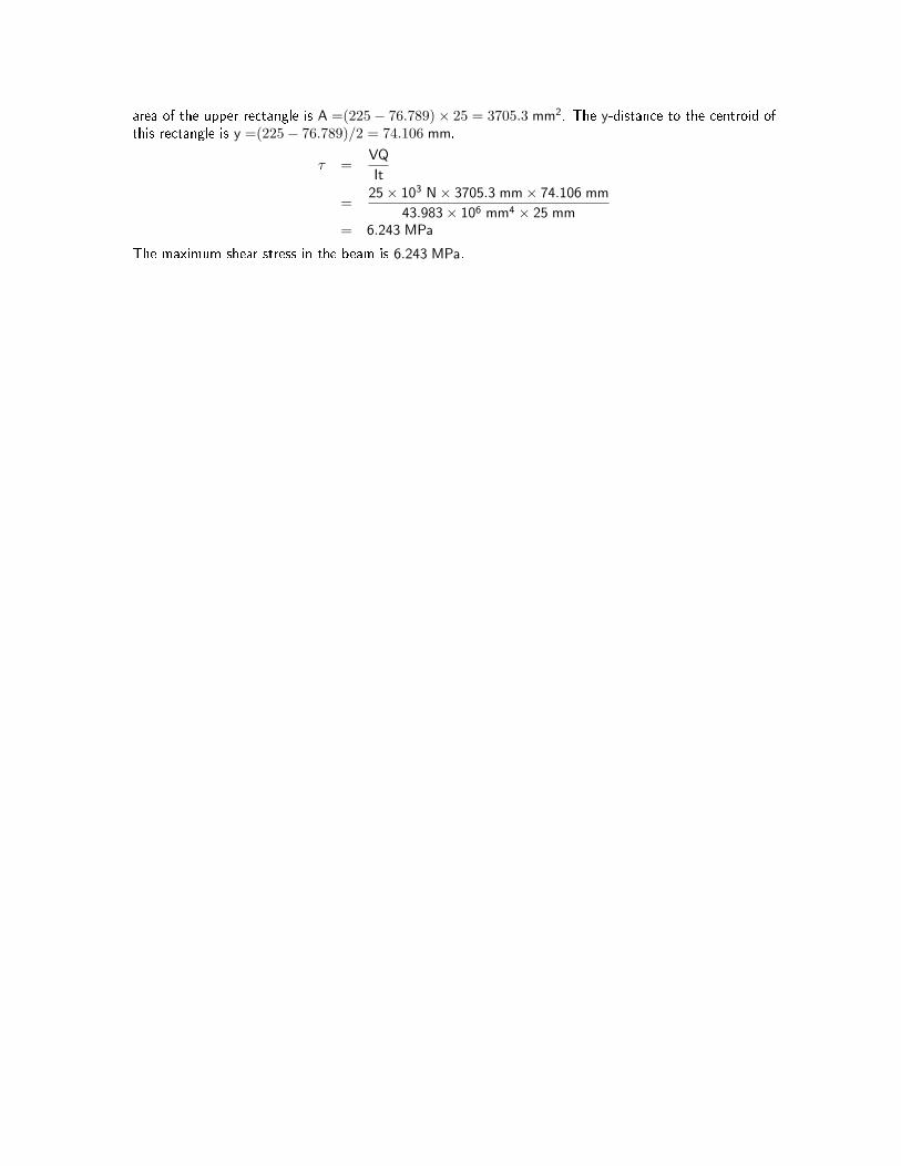
area of the upper rectangle is A =(225− 76.789)× 25 = 3705.3 mm2. The y-distance to the centroid ofthis rectangle is y =(225− 76.789)/2 = 74.106 mm.
τ =VQ
It
=25× 103 N× 3705.3 mm× 74.106 mm
43.983× 106 mm4 × 25 mm= 6.243 MPa
The maximum shear stress in the beam is 6.243 MPa.