bengt johansson high efficiency kaust future fuels ... · lund university john a. gaynor ... what...
TRANSCRIPT
Future fuels
byBengt Johansson
Clean combustion research centerKAUST

Future fuels
2
EnergySource
Energy carrier
Energy usage
Well to Tank Tank to Wheel
Well to Wheel
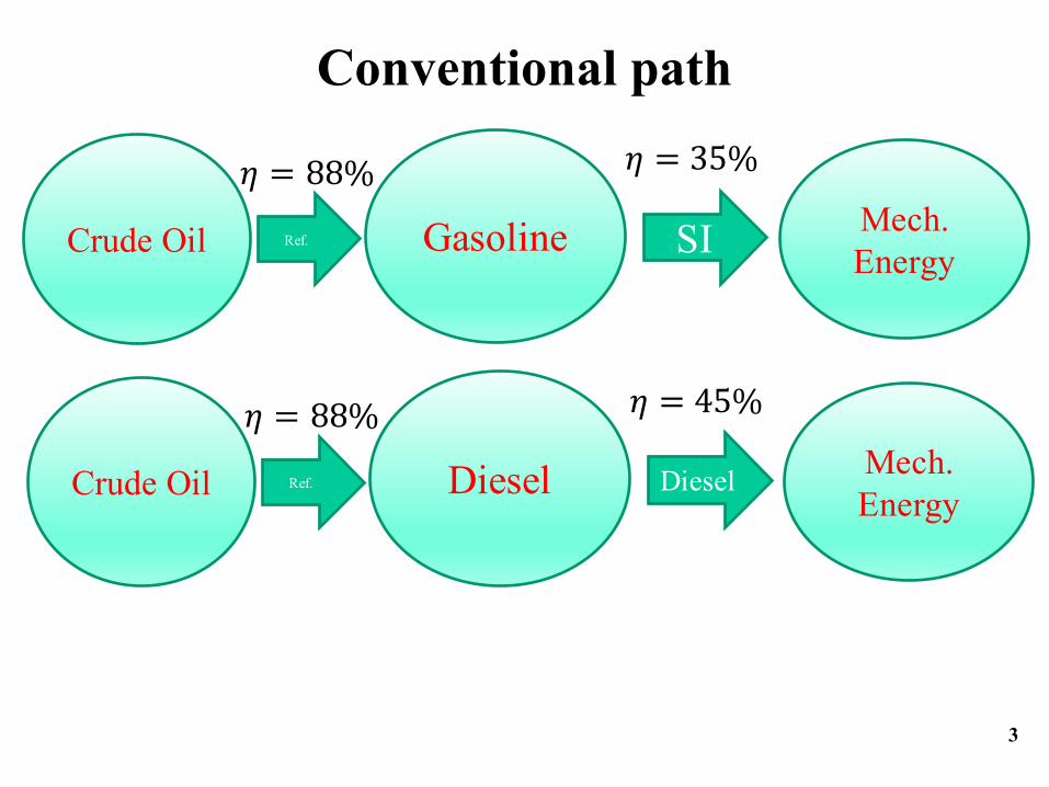
Conventional path
3
Gasoline Mech. Energy
Ref. SICrude Oil
𝜂 = 88% 𝜂 = 35%
Diesel Mech. Energy
Ref. DieselCrude Oil
𝜂 = 88% 𝜂 = 45%

Improve engine efficiency
4
Gasoline /Diesel
Mech. Energy
Ref. 8-strokeCrude Oil
𝜂 = 88% 𝜂 = 60%
Gasoline /Diesel
Mech. Energy
Ref. PPCCrude Oil
𝜂 = 88% 𝜂 = 50%

Improve fuel processing
5
Naphtha Mech. Energy
Ref. PPCCrude Oil
𝜂 = 94% 𝜂 = 50%
Gasoline /Diesel
Mech. Energy
Ref. PPCCrude Oil
𝜂 = 88% 𝜂 = 50%

Biofuel with fermentation
6
Ethanol Mech. Energy
Ferm. SIBiomass
𝜂 = 30% 𝜂 = 35%

Biofuel with better ICE
7
Ethanol Mech. Energy
Ferm. SIBiomass
𝜂 = 30% 𝜂 = 35%
Ethanol Mech. Energy
Ferm. CIBiomass
𝜂 = 30% 𝜂 = 43%
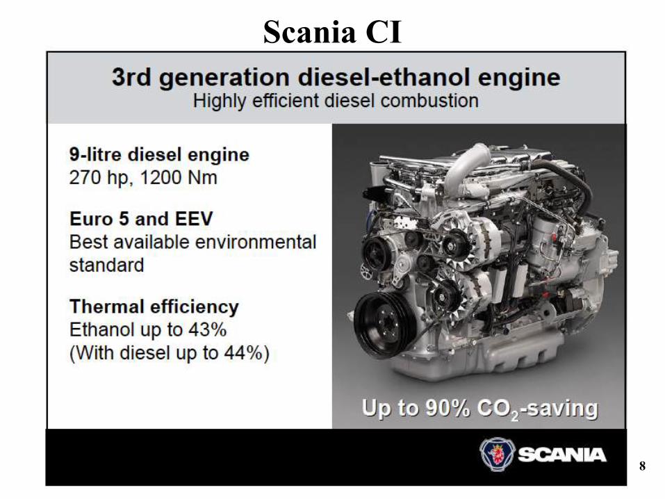
Scania CI
8

Scania CI
9

Scania CI
10
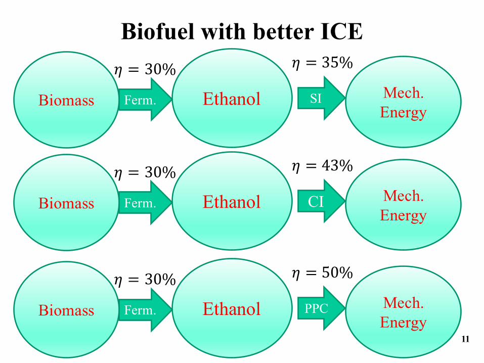
Biofuel with better ICE
11
Ethanol Mech. Energy
Ferm. SIBiomass
𝜂 = 30% 𝜂 = 35%
Ethanol Mech. Energy
Ferm. CIBiomass
𝜂 = 30% 𝜂 = 43%
Ethanol Mech. Energy
Ferm. PPCBiomass
𝜂 = 30% 𝜂 = 50%

Experimental Investigation on Different Injection Strategies
for Ethanol Partially Premixed Combustion
SAE 2013-01-0281
Mehrzad Kaiadi, Bengt Johansson, Marcus LundgrenLund University
John A. GaynorScania CV AB

Biomass Conversion via Syngas
13
Methanol Mech. Energy
PPCBiomass
𝜂 = 68% 𝜂 = 50%

Methanol PPC
14

Methanol = Liquid methane
15
Natural gas
Methanol Mech. Energy
PPCBiomass
𝜂 = 68%
𝜂 = 70 − 78%
𝜂 = 50%

16
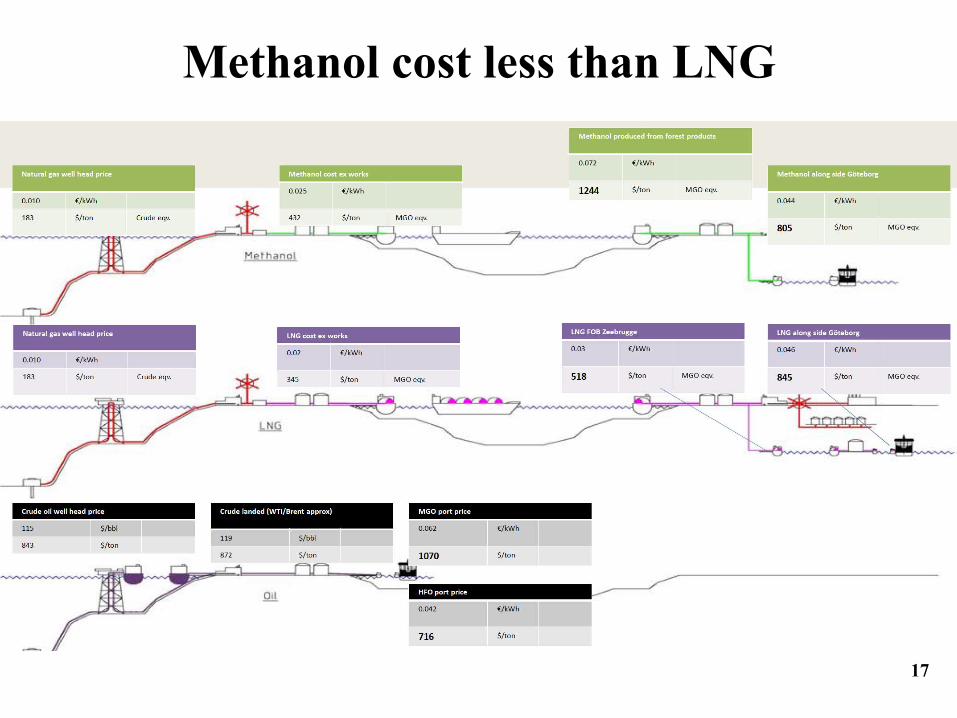
Methanol cost less than LNG
17

Methanol cost less than LNG
18

Electrofuel
19
Natural gas
Methanol Mech. Energy
PPCBiomass
Electricity
𝜂 = 68%
𝜂 = 78%
𝜂 = ~70 − 80%
𝜂 = 50%

Electrofuels, really?
20
Methanol Mech. Energy
PPC
Electricity 𝜂 = ~70 − 80%
𝜂 = 50%
𝜂 = ~98%

With 100% renewable electricity
21
IF wind power should be sufficient also with low wind, we need much more power than average (1/capacity factor) and hence most of the time we have a surplus of energy.Use this surplus elctricity to make fuel (energy storage)
Wikipedia: “Capacity factor”

Example of How to Produce Electrofuels, Maria Grahn, Chalmers
Biomass(C6H10O5)
Electro-lysis
Water (H2O)
Hydrogen(H2)
H2
Electro-fuels Biofuels
Methane (CH4)Methanol (CH3OH)DME(CH3OCH3)Ethanol (C2H5OH)
CO2
Power
Allbiofuelproductiongenerates”waste CO2”
CO2 fromairandseawater
CO2 fromcombustion
Sabatierreactor
Biofuelproduction
Denmark already had periods with negative price on electricity

Tank-Wheel study
Review and Benchmarking of Alternative Fuels in Conventional and Advanced Engine Concepts
To be published in SAE 2016-01-0882
by Martin Tuner, Lund University
23

SAE 2016-01- 0882
24

Towards 60% efficient IC engine
byBengt Johansson
Clean combustion research centerKAUST

What is a high efficiency?
Any text book on ICE:• Ideal cycle with heat addition at
constant volume:
• With a compression ratio of 60:1 and γ=1.4 we get an efficiency of 80,6%
• Why then do engines of today have an efficiency of 20-40%???
26

Outline
• What is high efficiency?• Combustion, thermodynamic, gas exchange
and mechanical efficiencies. All four must be high.
• Combustion to enable high efficiency• HCCI• Partially Premixed Combustion
• Can we do something about engine design?
• Conclusions

Energy flow in an IC engine
FuelMEP
QhrMEP
IMEPgross
lMEPnet
BMEP
QemisMEP
QlossMEP
QhtMEP
QexhMEP
PMEP
FMEP
Combustion efficiency
Thermodynamic efficiency
Gas exchange efficiency
Mechanical efficiency
Net Indicated efficiency
Brake efficiency
Gross Indicated efficiency
FuelMEP
QhrMEP
IMEPgross
lMEPnet
BMEP
QemisMEP
QlossMEP
QhtMEP
QexhMEP
PMEP
FMEP
Combustion efficiency
Thermodynamic efficiency
Gas exchange efficiency
Mechanical efficiency
Net Indicated efficiency
Brake efficiency
Gross Indicated efficiency
ηηηηη MechanicaleGasExchangmicThermodynaCombustionBrake***=

Outline
• What is high efficiency?• Combustion, thermodynamic, gas exchange
and mechanical efficiencies. All four must be high.
• Combustion to enable high efficiency• HCCI• Partially Premixed Combustion
• Can we do something about engine design?
• Conclusions

30
HCCI -Thermodynamic efficiencySaab SVC variable compression ratio, VCR, HCCI, Rc=10:1-30:1; General Motors L850 “World engine”, HCCI, Rc=18:1, SI, Rc=18:1, SI, Rc=9.5:1Scania D12 Heavy duty diesel engine, HCCI, Rc=18:1;
Fuel: US regular Gasoline
SAE2006-01-0205

All four efficiencies
31
SAE keynote Kyoto 2007

Net indicated efficiency= ηC ηT ηGE
SI stdSI highHCCIVCR
Scania
+100%

Brake efficiencySI std
SI highHCCIVCR
Scania
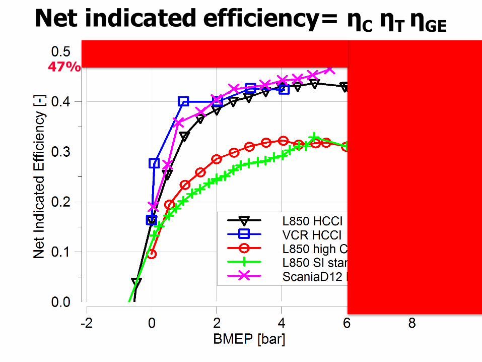
Net indicated efficiency= ηC ηT ηGE
SI stdSI highHCCIVCR
Scania
47%

Outline• What is high efficiency?
• Combustion, thermodynamic, gas exchange and mechanical efficiencies. All four must be high.
• Combustion to enable high efficiency• HCCI• Partially Premixed Combustion
• Can we do something about engine design?
• Conclusions

PPC - Diesel engine running on gasoline
0 2 4 6 8 10 12 1420
25
30
35
40
45
50
55
60
Gross IMEP [bar]
Gro
ss In
dica
ted
Effic
ienc
y [%
]
Group 3, 1300 [rpm]
FR47333CVXFR47334CVXFR47336CVX
HCCI: ηi=47% => PPC: ηi=57%
36

Partially Premixed Combustion, PPC
37
-180 -160 -140 -120 -100 -80 -60 -40 -20
1000
2000
3000
4000
5000
6000Spridare 8x0.12x90 & 8x0.12x150, Iso-oktan, CR-tryck 750 bar, Duration 0,6 ms = 3.6 CAD
HC
[ppm
]
SOI [ATDC]-180 -160 -140 -120 -100 -80 -60 -40 -20
200
400
600
800
1000
1200
NO
x [p
pm]
Def: region between truly homogeneous combustion, HCCI, and diffusion controlled combustion, diesel
HCCI
PPC
CI
SAE 2004-01-2990

PPC: Effect of EGR with diesel fuel
38
Load 8 bar IMEPAbs. Inlet Pressure 2.5 barEngine Speed 1090 rpm
Swirl Ratio 1.7Compression Ratio 12.4:1 (Low)
DEER2005 and SAE 2006-01-3412
Scania D12 single cylinder

1
43
2

40
PPC with low cetane diesel
Lic. Thesis by Henrik Nordgren2005 and presented at DEER2005

41
Efficiencies 17.1:1
4 5 6 7 8 9 10 11 12 1350
55
60
65
70
75
80
85
90
95
100
Gross IMEP [bar]
[%] Combustion Efficiency
Thermal EfficiencyGas Exchange EfficiencyMechanical Efficiency
SAE 2009-01-2668
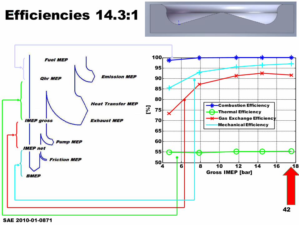
42
4 6 8 10 12 14 16 1850
55
60
65
70
75
80
85
90
95
100
Gross IMEP [bar]
[%] Combustion Efficiency
Thermal EfficiencyGas Exchange EfficiencyMechanical Efficiency
Efficiencies 14.3:1
SAE 2010-01-0871
4343
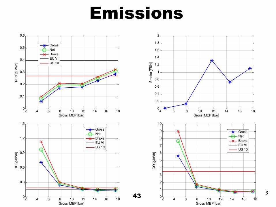
4 6 8 10 12 14 16 180
0.2
0.4
0.6
0.8
1
1.2
1.4
1.6
1.8
2
Smok
e [F
SN]
Gross IMEP [bar]2 4 6 8 10 12 14 16 18
0
0.1
0.2
0.3
0.4
0.5
0.6
Gross IMEP [bar]
NO
x [g
/kW
h]
GrossNetBrakeEU VIUS 10
2 4 6 8 10 12 14 16 180
1
2
3
4
5
6
7
8
9
10
Gross IMEP [bar]
CO
[g/k
Wh]
GrossNetBrakeEU VIUS 10
2 4 6 8 10 12 14 16 180
0.3
0.6
0.9
1.2
1.5
Gross IMEP [bar]
HC
[g/k
Wh]
GrossNetBrakeEU VIUS 10
Emissions

44
Emissions – different fuels
2 4 6 8 10 12 14 16 18 200
0.5
1
1.5
2
2.5
Gross IMEP [bar]
Soot
[FSN
]
EthanolFR47330CVXFR47331CVXFR47333CVXFR47334CVXFR47335CVXFR47336CVXFR47338CVX
2 4 6 8 10 12 14 16 18 200
0.05
0.1
0.15
0.2
0.25
0.3
0.35
0.4
0.45
0.5
Gross IMEP [bar]
NO
x [g
/kW
h]
EthanolFR47330CVXFR47331CVXFR47333CVXFR47334CVXFR47335CVXFR47336CVXFR47338CVX
2 4 6 8 10 12 14 16 18 200
2
4
6
8
10
12
Gross IMEP [bar]
CO
[g/k
Wh]
EthanolFR47330CVXFR47331CVXFR47333CVXFR47334CVXFR47335CVXFR47336CVXFR47338CVX
2 4 6 8 10 12 14 16 18 200
1
2
3
4
5
6
7
8
9
10
Gross IMEP [bar]
HC
[g/k
Wh]
EthanolFR47330CVXFR47331CVXFR47333CVXFR47334CVXFR47335CVXFR47336CVXFR47338CVX
SAE 2010-01-0871

4545
Experimental Apparatus, Scania D13
XPI Common RailOrifices 8 [-]
Orifice Diameter 0.19 [mm]
Umbrella Angle 148 [deg]
Engine / Dyno SpecBMEPmax 25 [bar]
Vd 2124 [cm3]
Swirl ratio 2.095 [-]
Standard piston bowl, rc: 17.3:1SAE 2010-01-2198
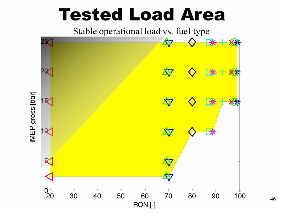
4620 30 40 50 60 70 80 90 1000
5
10
15
20
25
RON [-]
IMEP
gro
ss [b
ar]
Stable operational load vs. fuel typeTested Load Area

47
Efficiency with Diesel or Gasoline
5 10 15 20 25 3034
36
38
40
42
44
46
48
50
52
Gross IMEP [bar]
Brak
e Ef
ficie
ncy
[%]
D13 GasolineD13 Diesel
Average improvement of 16.6% points at high load by replacing diesel fuel with gasoline!

1.5 2 2.5 3 3.544
46
48
50
52
54
56
58G
ross
Indi
cate
d Ef
ficie
ncy
[%]
Abs Inlet Pressure [bar]
FR47338CVXFR47335CVXFR47334CVX
Gross Indicated Efficiency
SAE paper 2010-01-1471
10%!

Outline• What is high efficiency?
• Combustion, thermodynamic, gas exchange and mechanical efficiencies. All four must be high.
• Combustion to enable high efficiency• HCCI• Partially Premixed Combustion
• Can we do something about engine design?
• Conclusions

High efficiency thermodynamics:Simulation results from GT-power
• Indicated efficiency 65,2%• Brake efficiency 60.5%

Is 65% possible?Any text book on ICE:• Ideal cycle with heat addition at constant
volume:
• With a compression ratio of 60:1 and γ=1.4 we get an efficiency of 80,6%
51

0 10 20 30 40 50 60 700
100
200
300
400
500
600
700
800
900
1000Peak cylinder pressure as function of compression ratio
Peak
cyl
inde
r pre
ssur
e [b
ar]
Compression ratio
Lambda = 1.2Lambda = 3.0
There are a few drawbacks…
– Engine structure must be very robust (if at all possible)
– Very high friction and hence lower mechanical efficiency
52

There are a few drawbacks…
530 10 20 30 40 50 60 7020
30
40
50
60
70
80
90Thermodynamic efficiency as function of compression ratio
Compression ratio
Ther
mod
ynam
ic e
ffici
ency
[%]
No heat transfer lossesWith heat transfer losses (Woschni)

How then make 60:1 usable?
• Swedish proverb: ”Den late förtar sig hellre än går två gånger”
• Which according to google translate means: ”The lazy man rather breaks his back than walk twice”
54

Take it in steps!How about
𝟔𝟎 = 𝟕. 𝟕𝟓If we divide the compression in two equal stages the total pressure (and temperature) ratio will be the product of the two
7.75:1 x 7.75:1=60:1
With a peak pressure of 300 bar the pressure expansion ratio is 300:1 and hence 300^(1/1.4)=58.8.1 in volume ratio(gamma=1.25 during expansion gives 96:1)
55

Split cycles from the past
56

From history: Compound Engine
Divide the expansion in three cylinders with same force, F, on each piston.
The smaller cylinder has higher pressure but also smaller areaF=p*A
57

58

Split cycles from the present
59

Three step compression in production• To run a smaller engine at
higher load turbocharging is used. The engine is using two or three shafts of which only one can generate power
• High BMEP (up to 30 bar) results with two-stage turbo
• Peak pressure 200 bar
60F. Steinparzer, W. Stütz, H. Kratochwill, W. Mattes: „Der neue BMW-Sechzylinder-Dieselmotor mit Stufenaufladung“, MTZ, 5,2005

Divide the process into two cylinders
Low pressure cycle
• Use large naturally aspirated engine designed for 30 bar peak pressure – Load range 0-5 bar
BMEP– Peak pressure during
the cycle 30 bar
• Friction FMEP 0.05-0.1 bar
High pressure cycle
• Use small engine with 300 bar peak pressure feed by the large engine
– Load range 35-80 bar BMEP
– Peak pressure during the cycle 250-300 bar
• Friction FMEP 1.2-2.2 bar
61
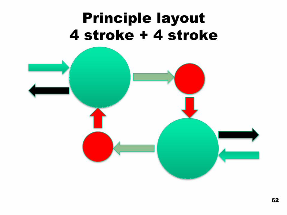
Principle layout 4 stroke + 4 stroke
62

Operating cycle 4 + 4 stroke
63
Inlet
Inlet
Inlet
Inlet
Compression Expansion
Compression
Compression
Compression Expansion
Expansion
Expansion
Exhaust
Exhaust
Exhaust
Exhaust
TDC TDCTDC
TDC
TDC
TDC TDC
TDC
TDCTDC BDCBDC
BDC BDC
BDCBDC
BDCBDC1
1
3
3
22
4 4
Pre
ssu
re
Combustion

DOUBLE COMPRESSION EXPANSION ENGINE CONCEPTS: A PATH TO HIGH
EFFICIENCY
Nhut Lam, Martin Tunér, Per Tunestål, Bengt Johansson, Lund University
Arne Andersson, Staffan Lundgren, Volvo Group
SAE 2015-01-1260

Conceptual design 4-4
65
SAE 2015-01-1260

Simulation study - Inputs
66
Simulation model DCEE DCEE Conv, Conv.Lambda, λ 1.2 3.0 1.2 3.0Bore, HP-cylinder [mm] 95 95 317 249Stroke, HP-cylinder [mm] 100 100 100 100HP-displacement [dm^3] 0.71 0.71 7.9 4.9Compr. ratio, HP-cylinder [-] 11.5 11.5 55 55Bore, LP-cylinder [mm] 317 249 - -Stroke, LP-cylinder [mm] 100 100 - -LP-displacement [dm^3] 7.9 4.9 - -Charge air cooler temp (K) 350 - - -
SAE 2015-01-1260
DCEE=Double Compression Expansion Engine

High Pressure cylinder
67
SAE 2015-01-1260

Low Pressure cylinder
68
SAE 2015-01-1260

Combined
69
SAE 2015-01-1260

Heat Transfer
• To reduce heat transfer: – Reduce heat transfer coeff., h– Reduce surface area, A– Reduce gas temperature– Increase wall temperature
70
!"!" = ℎ!!!(!! − !!)!

Wall surface area
710 1 2 3 4 5 6 7 8 9
0
0.05
0.1
0.15
0.2
0.25
0.3
0.35
Cylinder volume [dm3]
Area
[m2 ]
Wall surface area as function of cylinder volume
DCEE, lambda 1.2DCEE, lambda 3.0CI, lambda 1.2CI, lambda 3.0
SAE 2015-01-1260

Area/volume-ratio
72
0 1 2 3 4 5 6 7 8 90
200
400
600
800
1000
1200
Cylinder volume [dm3]
Area
/Vol
ume
[m2 /m
3 ]Wall surface area per volume as function of cylinder volume
DCEE, lambda 1.2DCEE, lambda 3.0CI, lambda 1.2CI, lambda 3.0
SAE 2015-01-1260

Heat transfer losses
73

SAE 2015-01-126074
Estimation of friction mean effective pressure, FMEP
0 50 100 150 200 250 3000
0.2
0.4
0.6
0.8
1
1.2
1.4
1.6
1.8FMEP as function of PCP
FMEP
[bar
]
PCP [bar]Designed engine peak cylinder pressure
Naturally aspirated SI-engine @ 2300 rpm
Traditional heavy duty turbocharged CI engine
HP cylinder, DCEE-concept
LP cylinder, DCEE-concept
•Friction is assumed to scale with Peak Cylinder Pressure, Pmax
•FMEP assumed to be 1.2 bar @200 bar Pmax
SAE 2015-01-126075
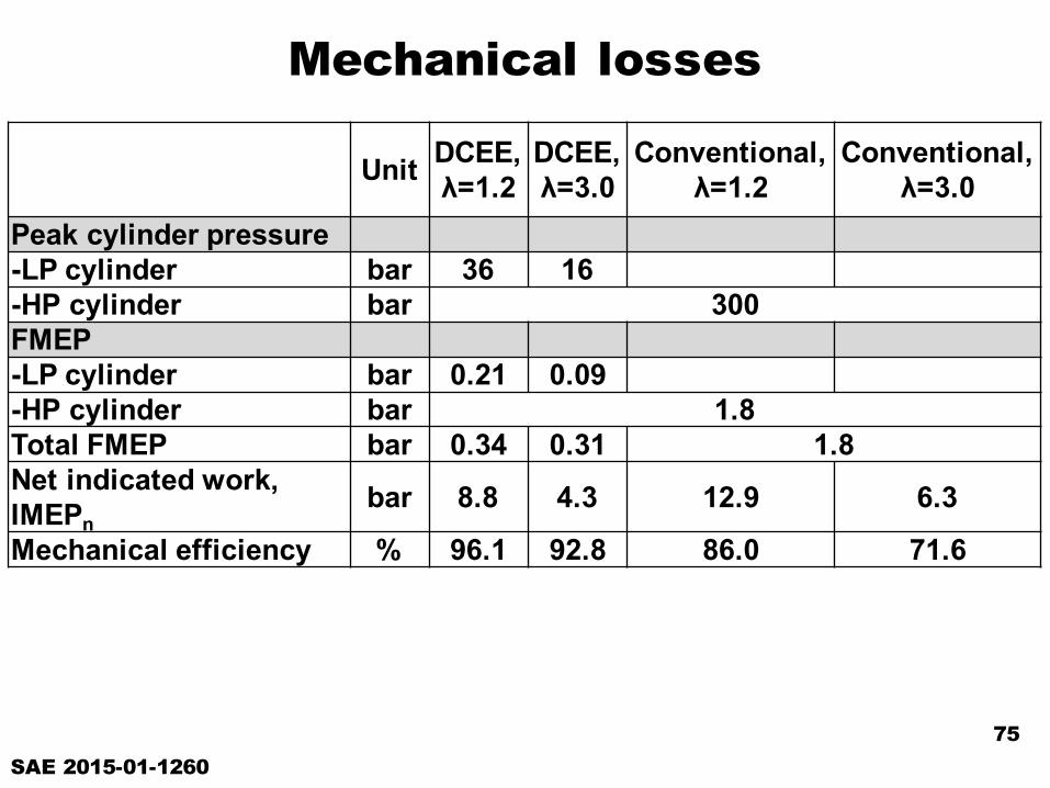
Mechanical losses
Unit DCEE, λ=1.2
DCEE, λ=3.0
Conventional, λ=1.2
Conventional, λ=3.0
Peak cylinder pressure-LP cylinder bar 36 16-HP cylinder bar 300FMEP-LP cylinder bar 0.21 0.09-HP cylinder bar 1.8Total FMEP bar 0.34 0.31 1.8Net indicated work, IMEPn
bar 8.8 4.3 12.9 6.3
Mechanical efficiency % 96.1 92.8 86.0 71.6

Resulting Efficiencies
76
SAE 2015-01-1260
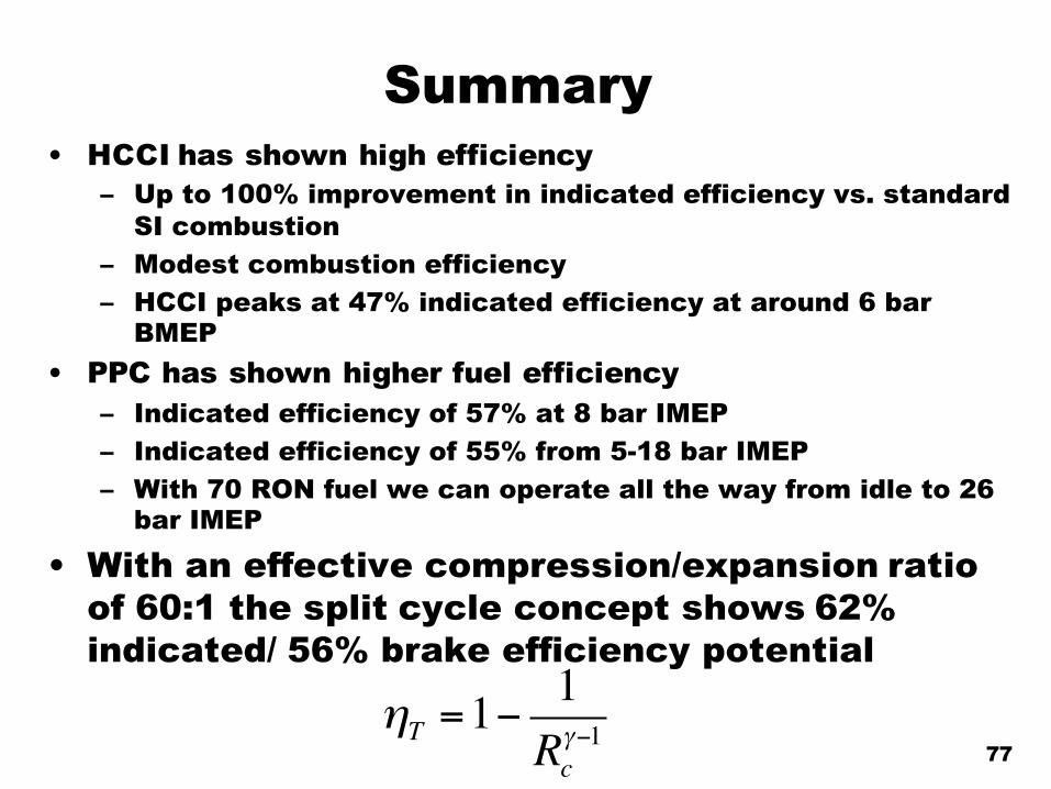
Summary• HCCI has shown high efficiency
– Up to 100% improvement in indicated efficiency vs. standard SI combustion
– Modest combustion efficiency– HCCI peaks at 47% indicated efficiency at around 6 bar
BMEP• PPC has shown higher fuel efficiency
– Indicated efficiency of 57% at 8 bar IMEP– Indicated efficiency of 55% from 5-18 bar IMEP– With 70 RON fuel we can operate all the way from idle to 26
bar IMEP
• With an effective compression/expansion ratio of 60:1 the split cycle concept shows 62% indicated/ 56% brake efficiency potential
77ηT =1−
1Rcγ−1

High Efficiency Combustion Engines – What is the limit?
“It all starts at 40 and ends at 60”(% engine efficiency that is, not life)
Prof. Bengt Johansson
CCRCKAUST

Thank you!
79

Future fuels
byBengt Johansson
Clean combustion research centerKAUST