bentley miniature railway · index 1 terms and conditions 2 locomotive description 3 locomotive...
TRANSCRIPT
Bentley Miniature Railway(wholly owned by Uckfield Model Railway Club Ltd.,
a Company limited by Guarantee. No.3824818Registered address: PO Box 263 Uckfield, East Sussex TN22 9BY)
Club Steam Locomotive
Operating and Maintenance Manual
Printed Version 2.0 (agreed text version 7.0)March 2013
1

2
Index
1 Terms and Conditions
2 Locomotive Description
3 Locomotive Preparation
4 Locomotive Disposal
5 Locomotive Operation
6 Dealing With Emergencies
Appendix 1 Responsible Drivers
Appendix 2 Lubrication Schedule
Appendix 3 Boiler Management
Appendix 4 Operating Log
Appendix 5 Faults Log
3

4

1. Terms and Conditions
1.1 This Manual has been produced to formalise and control the way the club locomotive is used and by introducing best practice hopefully improve its reliability and extend its life.
1.2 The club locomotive is to be used for training club members and to provide steam traction when required by the Duty Manager. The Duty Manager will decide when the locomotive is used.
1.3 Only those members listed in Appendix 1 - Responsible Drivers can ‘sign out’ the loco and by so doing agree to follow the procedures set out in this Manual. Other members can use the loco under the direction of the ‘Responsible Driver’.
1.4 Details of the loco’s use and those involved with it together with details of any faults must be recorded in the appropriate section of the Manual.
1.5 Any potentially serious faults such as evidence of boiler leakage, injector problems or problems with the gauge glasses must be referred to the responsible driver (who may not be the person to find the faults) who will decide whether it is safe to continue to steam the loco. If the Loco Manager is present he must be advised. The Duty Manager must be kept informed.
5

6

2. Locomotive Description
The club loco is a one third scale replica of a narrow gauge contractor’s locomotive made by a company called Hunslet Engine Company who had their works in Leeds. The design was very popular around the turn of the twentieth century and was widely used in slate quarries.
The club loco like the full size has outside cylinders and inside Stephenson’s valve gear. The outside and inside being references to their relationship to the frames. The frames themselves are outside the wheels and drive to the wheels is via fly cranks, which can be seen outside the frames.
Although there is a water tank located above the boiler this is not used due to its limited capacity. The working water tank is in the driving truck.
The loco has a steel boiler with copper fire tubes. Steam is supplied direct to the cylinders via an internal regulator valve and as such is referred to as a ‘saturated’ steam loco. This means the steam is at the same temperature as the boiling water. The working pressure is 80psi which means the steam temperature is circa 150 degrees centigrade, half as hot again as in a boiling kettle.
The loco has two injectors for putting water into the boiler, and uses a coal fire for boiling the water and producing the steam.
There is a hand brake fitted to the loco and a vacuum ejector and brake handle for operating the train brakes.
The locomotive is not a toy and has the potential to cause serious personal injury if misused. Treat it with respect and if in doubt ASK.
7

8
3. Locomotive Preparation.
Please allow approximately one and a quarter hours to prepare the loco for service.
3.1 Only the Duty Manager can authorise the use of the club loco, but once agreed the ‘Responsible Member’ will need to ‘sign out’ the loco and read the O & M sheets to see when it was last used and whether any defects were noted.
3.2 Assuming it is OK the loco can be removed from the shed and inspected for any obvious defects or damage or loss of water. The boiler water level should be established, which if there are no leaks should be above the top of the gauge glass.
3.3 If all is OK the loco can be moved to the steaming bay where a more detailed examination should be carried out.
3.4 Separate the driving truck from the loco.
3.5 The first job will be to rod through the boiler fire tubes. To get at all the tubes it will be necessary to clean from both ends of the boiler.
3.6 When done clean out the smoke box and inspect. Check for any signs of water leakage.
3.7 Position the loco, e.g. at the edge of the turntable, so that the ash pan is clear of the track and apply the handbrake. Remove the two brass loose-fitting screws from the rear footplate and remove footplate. Remove the ash pan retaining pin and drop the remains of the previous fire. Inspect inside the fire box for signs of leakage.
3.8 Clean the grate.
3.9 Replace grate and ashpan.
3.10 Check the operation of the gauge glasses and then lower the water level to just over half a glass by opening the blowdown valve. Check that both gauge glasses show the same level.
3.11 Replace rear footplate.
3.12 Check that the regulator is closed and that the reverser is in mid gear. Check that the drain cocks are open. Open both injector steam valves and check that the blower and ejector valves are closed.
9
3.13 Check the water level in the driving truck tank and top up preferably with treated water (Mains water can be used when in the steaming bay area or if treated water is not available).
3.14 Add one measure (20ml) of water treatment to the tank.
3.15 Reconnect the driving truck and vacuum pipework to loco.
3.16 Before reconnecting the water pipework open the injector water valves to flush through the pipework, then reconnect pipework and check for a flow from the injector overflows.
3.17 no longer used
3.18 Check operation of the electric blower and place in chimney. There is no need to continue running the blower at this stage. See 3.19 below.
3.19 Cover the grate with a layer of paraffin soaked charcoal to a depth of about one and a half inches.
3.20 Light the charcoal and immediately turn on the blower. Note the time and do not force the engine into steam, this should take at least thirty minutes allowing a further fifteen minutes for it to reach working pressure. Experience will dictate whether it is necessary to keep the damper closed and crack open the fire box door (which should normally be kept shut) to achieve these times.
3.21 Allow one or two minutes for the charcoal to become thoroughly alight, then add some coal. Use only the medium sized anthracite. Repeat as necessary to maintain a medium sized fire i.e below the level of the fire box door.
3.22 Whilst the engine is coming into steam proceed to ‘oil up’ as described in Appendix 2.
3.23 Carry out general cleaning. Use a household polish such as “Mr. Sheen” for cleaning the paintwork. It is also good at removing oil but paraffin will be cheaper. Use Brasso on the copper and brass.
3.24 When steam is seen at the injector overflows close their steam valves.
3.25 Open the blower valve as soon as the pressure gauge is seen to have moved off its stop and open the ash pan damper to the first notch on the handle.
3.26 Remove the electric blower.
10
3.27 As the pressure rises progressively close in the blower valve to prevent its excessive use.
3.28 At about 50 psi try both injectors. Both must work perfectly.Check each injector as follows:• First fully open the water valve and check that water appears
from the injector overflow• Open widely the steam valve. If the injector is working correctly
there should be no discharge from the overflow.• If steam appears close the steam valve and when water
reappears open slowly the steam valve. If steam reappears there could be a problem with the injector. Try once again closing and opening the steam valve.
• If after opening the steam valve water is still present at the overflow close in slowly the water valve, the injector should now ‘pick up’. If steam reappears try again from the beginning.
If the injector fails to work check there are no air bubbles in the water pipework between the driving truck and loco. This would indicate an air leak and connections need to be checked. Failure of an injector means the loco is a failure.
3.29 Now with the boiler under pressure check each gauge glass as follows:• Close both the water and steam cocks• Open the drain cock• Open the steam cock and check for steam issuing from the
drain. Close the steam cock.• Open the water cock and check for water/steam issuing from the
drain. Close the water cock.• Close the drain cock and open first the steam cock followed by
the water cock.Repeat for second gauge glass.
3.30 Try both injectors at full working pressure. Both must work perfectly.
3.31 Drop the pressure back by adding water to the boiler until a full glass is obtained.
3.32 Again remove the rear section of the footplate and use the blowdown valve to lower the water level to half a glass. Replace rear footplate.
3.33 Top up the driving truck water tank.
3.34 Check the operation of the vacuum ejector by opening it’s steam valve and operating the brake valve. The vacuum should be between 15 to 20 inches of mercury.
11

3.35 Check the operation of the whistle.
3.36 Add coal to bunker.
3.37 Check that the firing irons and lubricating oils are in the driving truck.
The locomotive is now ready to enter service. Inform the Duty Manager and await his instructions.
12

4. Locomotive Disposal
Please allow approximately three quarters of an hour to dispose of the loco.
On arrival back at the steaming bay proceed as follows ensuring first that there remains sufficient fire to do so.
4.1 Ensure the regulator is closed, the drain cocks are open and apply the hand brake.
4.2 Carefully obtain a sample of boiler water from a gauge glass drain. Its colour will indicate whether sufficient water treatment is being used and the amount of suspended matter, which will determine the level of blowdown required.
4.3 Prepare the loco for a blowdown by filling the boiler to the top of the gauge glass.
4.4 Open the blowdown valve and reduce the water level to half a glass.
4.5 Repeat 4.3 and 4.4.
4.6 Fill the boiler above the level of the gauge glass. To monitor the level close the gauge glass water valve and clear the glass by opening the drain, then close the drain. Continue to use the injector until water appears in the gauge glass. Blow the gauge glass down a couple of times to confirm that the boiler is full. When full turn off the injector.
4.7 Close both gauge glasses.
4.8 Close the ashpan damper, blower valve and vacuum ejector steam valve. Check that the injector steam valves are closed.
4.9 Clean out any ash etc. from within the smokebox and check for leaks.
4.10 Carry out a general clean, inspecting for any defects whilst doing so.
4.11 Apply a coat of oil to any bright metal to prevent rusting.
4.12 Return the loco to the engine shed, again checking that the regulator is closed and the drains are open. Do not apply the hand brake. Check that the fire is out.
4.13 The Responsible Member must then record the day's event in the Operating Manual.
13

14
5. Locomotive Operation
Unlike full size steam locomotive operation where there is both a driver and fireman the operation of a miniature steam locomotive is down to just one person. However the work to be performed is the same. In full size practice the driver and fireman have different tasks (as the driver has overall responsibility for the locomotive he will also be aware of what the fireman is doing and of course was once a fireman himself) and in simple terms the driver is very much concerned with the ‘now’ situation whereas the fireman should always be thinking ahead. For example the driver will be thinking ‘do I have the road, has the guard given the right of way are the points set correctly, are the brakes off, am I travelling at the right speed etc.? The fireman on the other hand will be thinking about the journey ahead in terms of steam and water requirements and importantly preparing for it. So in miniature terms the driver has to be thinking of all these issues.
Thinking in terms of the ‘two roles’ the fireman’s role is basically to manage the boiler in a safe and efficient way. Safely largely means maintaining a water level in the boiler at all times, visible within the gauge glass, whatever the circumstances. The crown of the firebox must never be exposed.
Because steam cannot be produced at the flick of a switch this is where thinking ahead and route knowledge comes in. Knowing where the ups and downs are is vital to knowing when steam and water will be required. At Bentley the main demand for steam is from Bentley East to the top of the cutting in Glyndebourne Wood. As far as water is concerned the main change in level occurs when turning off the old line at Glyndebourne Wood for the extension. There is a fall in gradient here made worse by the need to apply braking for the foot crossing if the speed has not been reduced sufficiently beforehand.
Firing efficiently means having enough steam for the job in hand and ‘blowing off’ is wasteful and should be avoided. Severe blowing off can lead to priming and injector problems, a more serious condition.
Incomplete combustion indicated by excessive smoke is also wasteful as is running with the firebox door open. Producing dark smoke will be virtually impossible with smokeless fuel but something approximating to it is possible with household coal. Intelligent use of the blower and firebox door can prevent this.
Operating efficiently will provide no major cost savings but the driver should endeavour to raise his skill level and take pride in doing a ‘good job’.
Being on top of the fireman's role creates the time to concentrate on the driver's role. Struggling for steam and water or having problems with injectors for example will be a distraction for the driver and increase the risk of passing a signal at danger or committing some other similarly serious offence.
15
The driver’s role is to manage the locomotive and train in a safe manner. As far as the loco is concerned this requires an understanding of the loco’s construction to avoid both mechanical and thermal shock to working parts. Mechanical damage will occur if the loco is not properly lubricated, and damage to the cylinders may occur if they are not warmed through properly or priming occurs.
As far as the loco and train are concerned this means obeying the speed restrictions and signals at all times. Failure to do so is a serious offence.
It is not realistic to produce a step by step document on how to drive a steam locomotive as there are so many variables but the following Do’s and Don’ts are intended to provide guidance and detail some of the more important aspects of steam locomotive driving.
Do’s
1 Always check everything is working correctly before leaving the steaming bay.
2 Make sure the water level remains visible within the gauge glass and that both are showing the same level. If there are any reasons to suspect their accuracy check each gauge glass as described in the preparation section.
3 Think ahead in terms of steam and water requirements, fire and use the injectors accordingly.
4 To prevent severe blowing off the following stages of dealing with it should be followed:
• Add water to boiler and check that the blower is only cracked open;
• Close in the damper but do not fully close;• Crack open the firebox door, progressively opening until the
situation is under control;• Reverse procedure to restore normal operation.
5 Always ensure the cylinders are warmed through before closing the drain cocks. Drain cocks should be left open when the loco is cold and when warm waiting in the station platform.
6 When opening the regulator do so slowly and give the loco chance to respond to any adjustments.
7 Always start off in either full forward or reverse gear (depending upon the required direction of travel) and notch up towards mid gear as the speed increases.
16
8 Do top up the water tank whenever the opportunity arises. There is no excuse for running out of water. One round trip takes about two gallons.
9 Always observe the correct speed limits and obey all signals unless otherwise instructed.
10 When using the brake do so gradually (assuming it is not for an emergency). When coming to a complete stop try to stop on a ‘rising brake’. This means when the train actually stops the vacuum is actually rising, i.e. the brakes are being released. This avoids a sudden stop and is safer for the passengers. Once at a complete stop, fully re-apply the brakes to safely keep the train stationary.
11 When waiting in the platform with a train make sure the brakes are applied. Make sure they are released before attempting to move off.
12 Do ensure the loco is lubricated as detailed in Appendix 2 and regularly check oil in the mechanical lubricator is going down. During the course of a day's running expect to fill up the lubricator the equivalent of at least once.
13 Do add at least two or three measures of water treatment during its time in steam, as detailed in Appendix 3
Don’ts
1 Avoid excessive use of the blower. This should not be necessary if fired correctly. Rapid changes in boiler pressure should be avoided.
2 Don’t leave the loco unattended for any more than a few minutes. (If you have to, ask another driver to keep an eye on it).
3 Don’t be heavy handed with the regulator. This can cause wheel slip. Slip accelerates tread wear and can lead to other mechanical damage.
17

18
6. Dealing With Emergencies
Even with a well maintained loco and a competent driver things can go wrong and this section deals with some of the more likely failures.
The important issue is to deal with problems in a calm and professional way and avoid alarming the public. The public may not even be aware there is a problem and that’s the way it should remain.
As stated previously the loco is not a toy and has the potential to cause injury to both the driver and public if steps are not taken to minimise the risks. The driver should always be prepared to deal with failures and should have with him gloves and a heavy duty cloth. Their use will become obvious as the failures are considered.
Consider some of the more common failures:
6.1 Burst Gauge Glass.
Probably the most alarming failure for both the driver and public alike is the failure of a gauge glass. If on the move the train is to be brought to a stop as quickly as possible, then using the heavy duty cloth cover the gauge glass and finally close both cocks, This should only take a few seconds. Reassure the public, then proceed on the journey. As the failure of the second glass is unlikely the loco can remain in service. The glass must be replaced before the loco is next used.
6.2 Failure of Injectors
In itself the failure of one injector is not an emergency but the loco should be taken out of service to avoid the more serious risk if the second injector fails. The most likely reason for both injectors to fail would be running out of water!!!If both do fail because of the above reason and there is no immediate supply available then this is a loco failure and the boiler must be protected from serious over heating failure due to a low water level.
The quickest and simplest way to extinguish the fire is to close the ashpan damper, place a cloth in the chimney and crack open the blower. This will starve the fire of oxygen and the fire will soon go out. There will still be a lot of heat present but not enough to cause damage to the boiler.
(The ashpan and grate of the club loco can be dropped but this will immobilise the loco and may prevent services continuing, it may also cause damage to the loco).
If there is no immediate need to move the loco and the water cannot be seen in the gauge glass lift the front end of the loco until water appears.
19
6.3 Failure of a Feed Clack
Failure of a feed clack to shut properly will cause water loss and if severe may need treating as above to prevent damage to the boiler resulting from low water level. In the short term put the alternative injector on to maintain water levels and to get back to a station.
It may be possible to close the clack by giving it a gentle tap with a solid object such as one of the firing irons or a large spanner. If this fails try pouring some cold water over it.
If it cannot be closed and it prevents the use of the injector the loco is a failure and must be taken out of service.
6.4 Failure of the Regulator Valve
Quite rare but possible - if the linkage comes adrift or the internal steam pipe fractures. Control the speed on the reverser, drain cocks and brakes back to Bentley Central where the loco should be declared a failure.
20

Appendix 1 Responsible Drivers
The following members are allowed to sign out the club steam loco
Name (in alphabetic order) Status or Function at BMR
Derek Barlow Boiler InspectorGeoff Billington Boiler InspectorBarry Miller Safety OfficerBruce Morgans Club Loco ManagerJohn Pollington Operations Co-ordinator and Boiler ClerkPeter Southern Boiler Inspector
21

22
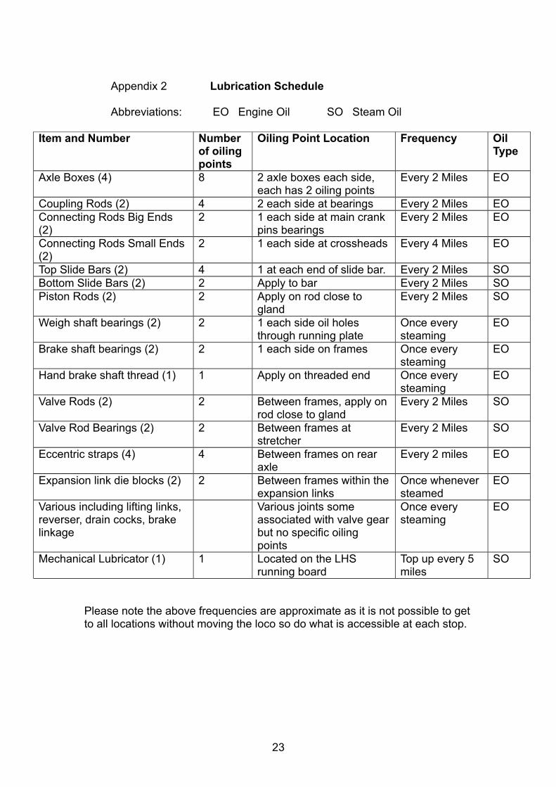
Appendix 2 Lubrication Schedule
Abbreviations: EO Engine Oil SO Steam Oil
Item and Number Number of oiling points
Oiling Point Location Frequency Oil Type
Axle Boxes (4) 8 2 axle boxes each side, each has 2 oiling points
Every 2 Miles EO
Coupling Rods (2) 4 2 each side at bearings Every 2 Miles EOConnecting Rods Big Ends (2)
2 1 each side at main crank pins bearings
Every 2 Miles EO
Connecting Rods Small Ends (2)
2 1 each side at crossheads Every 4 Miles EO
Top Slide Bars (2) 4 1 at each end of slide bar. Every 2 Miles SOBottom Slide Bars (2) 2 Apply to bar Every 2 Miles SOPiston Rods (2) 2 Apply on rod close to
glandEvery 2 Miles SO
Weigh shaft bearings (2) 2 1 each side oil holes through running plate
Once every steaming
EO
Brake shaft bearings (2) 2 1 each side on frames Once every steaming
EO
Hand brake shaft thread (1) 1 Apply on threaded end Once every steaming
EO
Valve Rods (2) 2 Between frames, apply on rod close to gland
Every 2 Miles SO
Valve Rod Bearings (2) 2 Between frames at stretcher
Every 2 Miles SO
Eccentric straps (4) 4 Between frames on rear axle
Every 2 miles EO
Expansion link die blocks (2) 2 Between frames within the expansion links
Once whenever steamed
EO
Various including lifting links, reverser, drain cocks, brake linkage
Various joints some associated with valve gear but no specific oiling points
Once every steaming
EO
Mechanical Lubricator (1) 1 Located on the LHS running board
Top up every 5 miles
SO
Please note the above frequencies are approximate as it is not possible to get to all locations without moving the loco so do what is accessible at each stop.
23

24

Appendix 3 Boiler Management
Boiler Management is about how we use the boiler to protect it from damage. The main parts of the boiler are made from steel which corrodes badly when wet and in the presence of oxygen i.e air. The products of combustion when damp or wet are also very corrosive so in both cases we use a number of strategies to protect it.
Finally the boiler can also be damaged through over heating caused by scale build up inside the boiler or running out of water.
The strategies used to protect the boiler are therefore as follows:
1. Water Treatment
Water treatment works by:
• Leaving a tannin protective coating on the metal surface• Absorbing the free oxygen in the water• Keeps the dissolved minerals in the water in suspension. These
minerals are then removed via blowdowns.
So the water treatment helps to prevent corrosion and over heating caused by scale build up.
A ‘start up’ charge of water treatment is added to the boiler whenever the boiler is filled with water at the start of the season, or following a boiler washout. It is then topped up before and during subsequent running.
The ‘start up’ charge is 2 cap measures (40ml)The top up charge is 1 cap measure (20ml) added to the driving truck tank at the start of the day with a further measure being added after every 5 miles of running.
A water sample is to be taken from the gauge glass drain at the end of each running day and retained until the next steaming. The aim is to end up with a sample that looks like a fine ‘brown ale’ fit to drink!!If there is any suspended matter this will give the sample a cloudy appearance and it may take over twenty four hours for it to settle. The purpose of the ‘blowdowns’ is to remove this suspended matter and control the level of dissolved matter, which cannot be seen but can be measured using a suitable meter. The higher the sediment levels the greater is the chance of priming and the higher the dissolved solids (tds) the greater is the chance of scale forming.The ph of the sample should be between 10.5 and 11.5 and the tds should be kept below 2000ppm.The Loco Manager will monitor the results throughout the year and advise if the water treatment dosage needs to be adjusted or whether additional blowdowns are required.
25
2. Taking time to raise steam
Both raising steam slowly and cooling the boiler down slowly are important to prevent thermal shock and unnecessary stresses within the boiler.
From cold to working pressure should not take less than forty five minutes and from cold to first signs of steam not less than thirty minutes. This process must not be rushed and the Duty Manager must not put the driver under pressure to ‘speed things’ up.
3. Taking time to cool the boiler down
Cooling down is just as important but in many ways easier to control. Once all blowdowns and checks have been carried out as detailed in the ‘disposal’ procedure the fire should be allowed to die down naturally and the loco returned to shed still warm and probably still in steam although by now the fire will be out. The remains of the fire will be left until the loco is cleaned by the next driver to sign it out.
4. Keeping the boiler clean
This applies to both inside and out. To keep the boiler internally clean this involves blowing the boiler down frequently to remove suspended matter and to control the dissolved solids and less frequently opening up around the foundation ring and flushing away any larger deposits not removed by the normal blowdown. The Loco Manager will arrange for the boiler to be ‘washed out’ after approximately every fifteen steamings. Both are important to prevent the build up of scale on the heating surfaces and preventing good circulation around the firebox.
The use of treated water which has typically one tenth of the minerals (hardness) than in untreated water significantly helps to keep the boiler clean and reduces the need for blowdowns.
Externally the tubes need to be cleaned regularly to prevent the build up of soot which not only reduces the boiler efficiency but when wet is very corrosive.
Finally the remains of the old fires need to be removed ASAP as these also become very acidic if they become damp or even worse, wet. For practical reasons the fires are to be dropped by the next driver to use the loco.
26
5. Correct storage
Here we apply two strategies, one for summer and one for winter.When the loco is being used regularly during the summer a ‘wet’ strategy is used whilst during the winter when the loco is out of service for several months a ‘dry’ strategy is used.
The wet strategy involves filling the boiler up to above the normal operating level i.e. above the top gauge glass cock, before the loco is returned to the shed at the end of a day's use, see disposal procedure.
The water in the boiler is relatively low in oxygen as most will have been released when converted to steam. Only the small space above the water level will be vulnerable as air is inevitably drawn into the boiler as it cools and tries to create a vacuum.
The dry strategy requires the boiler to be drained and dried out. Drying out is helped by removing several boiler fittings to allow the boiler to breathe and inserting a tubular heater into the firebox to provide warmth to assist the drying process.
The heater also maintains the metal work above the dew point of the air so that sweating and condensation does not occur whenever rapid temperature changes occur.
27

28

Appendix 4 Operating Log
Responsible Driver to complete whenever the club loco is used.
Date Responsible Driver
Other Drivers Reason for UsePassenger Service(S)
Training(T)
ApproxMileage(one complete circuit is one mile)
Have any faults been recorded in the Faults Log?
Are any repairs required before the loco can run again?
Sheet Number
29

30

Appendix 5 Faults Log
Date Responsible Driver
Fault Please give details (continue on other side if necessary)
Has the fault been referred to anyone?
Is Club Loco Manager aware of fault?
Sheet Number
31

32