bernard q- gun parts break down
DESCRIPTION
welding mig gun, Q gum Bernard parts breakdownTRANSCRIPT

196
2
Iner
t Gas
Equ
ipm
ent
BernardVendor Code: BER
Bernard Q-Guns configured with Custom Select are fitted at the factory with these Diffusers and Nozzles.• Bernard Q-Guns configured with electrode sizes of 1/16" or
smaller will be fitted at the factory with tube head diffusers where available.
• A wide variety of alternative front end parts are available to fit special applications.
The part number shown here, Q4010AE8EM, is an example of a typical configuration. It consists of a 400 AMP Q-Gun with a 15' cable, curved handle, locking trigger, rotatable short 45° neck, 7400 series 0.035" contact tip and a Miller® style direct plug.
Select the right MIG gun to fit your precise application requirements.A Bernard Q-Gun configured with Custom Select really is the right tool for the job. Why settle for anything less?• Build a part number for a new Q-Gun by selecting:
Amperage, Cable Length, Handle and Trigger, Neck, Contact Tip and Direct Plug.
Bernard Q-Gun™
Custom Select Ordering System for Bernard Q-Guns
Cable Lengthfeet m
08 8 2.44
10 10 3.05
12 12 3.66
15 15 4.57
20 20 6.16
25 25 7.63
AMP and Cable Type
Q15 150 AMP max. wire size: .045" (1.2 mm)
Q20 200 AMP max. wire size 1/16" (1.6 mm)
Q30 300 AMP max. wire size: 5/64" (2.0 mm)
Q40 400 AMP max. wire size: 5/64" (2.0 mm)
Q50 500 AMP max. wire size: 3/32" (2.4 mm)
Q60 600 AMP max. wire size: 1/8" (3.2 mm)
S30 300 AMP steel “Monocoil” max. wire size: 5/64" (2.0mm)
S40 400 AMP steel “Monocoil” max. wire size: 5/64" (2.0mm)
S50 500 AMP steel “Monocoil” max. wire size: 3/32" (2.4 mm)
S60 600 AMP steel “Monocoil” max. wire size: 1/8" (3.2 mm)
Combine steel Monocoil cable with OXO style handle and QuikTip for gun similar to former OXO APX gun.
*Only OXO style handle options can be used with Steel Monocoil power cable.
Q40 10 A
Handle and Trigger
150 AMP Curved HandleStandard Cable
Standard trigger A
200, 300 AMP Curved HandleStandard Cable
Standard triggerLocking trigger
Dual pull trigger
AB C
400 AMP Curved HandleStandard Cable
Standard triggerLocking trigger
Dual pull triggerDual schedule switch
Dual schedule switch w/lock
A BCDE
150-400 AMP* OXO Style Small Curved HandleStandard or Steel Monocoil
Standard triggerLocking trigger
T U
400-600 AMP* OXO Style LargeCurved Handle Standard or Steel Monocoil
Standard triggerLocking trigger
Dual pull triggerDual schedule switch
Dual schedule switch w/lock
GHIKL
www.oki-bering.com

197
2
Inert Gas Equipment
BernardVendor Code: BER
1 2 3 4 5 6 7 8 9 10 11 12 13 14 15 16 17 18 19 20 21 22 23 24
Custom Select Ordering System for Bernard Q-Guns
Illustrated below are the necks defined for Standard Q-Guns.Short 45° QT2-45, standard for 150, 200 AMPMedium 45° QT3-45, standard for 300, 400 AMPLong 60° QT5-60, standard for 500, 600 AMP
Neck
A Rotatable, short 30° QT2-30
B Rotatable, short 45° QT2-45
C Rotatable, short 60° QT2-60
J Rotatable, short 80° QT2-80
D Rotatable, medium 30° QT3-30
E Rotatable, medium 45° QT3-45
F Rotatable, medium 60° QT3-60
K Rotatable, medium 80° QT3-80
G Rotatable, long 30° QT5-30
H Rotatable, long 45° QT5-45
I Rotatable, long 60° QT5-60
N Fixed, short 30° QT2-30
O Fixed, short 45° QT2-45
P Fixed, short 60° QT2-60
W Fixed, short 80° QT2-80
Q Fixed, medium 30° QT3-30
R Fixed, medium 45° QT3-45
S Fixed, medium 60° QT3-60
X Fixed, medium 80° QT3-80
T Fixed, long 30° QT5-30
U Fixed, long 45° QT5-45
V Fixed, long 60° QT5-60
Contact Tip
8 Centerfire™
T Series tip
7 Elliptical, 7400 series, 1.25" long, std.
5 Quik Tip™
1 Elliptical, 1500 series, 2.00" long, HD
Wire SizeInches mm
A .023 0.6 B .030 0.8 C .035 0.9 D .039 1.0 E .045 1.2 H .052 1.4 I 1/16 1.6
K 5/64 2.0
L 3/32 2.4M 7/64 2.8 N 1/8 3.2
Direct Plug
B Bernard®
C L-Tec®
E Euro®
H Hobart®
L Lincoln®
M Miller®
N National®
O OXO®
S Tweco® 4(Lincoln lead)
T Tweco® 4 (std. lead)
U Tweco® 4 (two prongtwist-lock lead)
W Tweco® 5 (std. lead)
E 8 E M
Bernard® is the registered trademark of Illinois Tool Works, Inc. Other brands mentioned are for reference only and are the registered trade marks of their respective companies.
Typically Selected Necks by Amperage
150 - 200 AMP QT2-45300 - 400 AMP QT3-45500 - 600 AMP QT5-60
Wire SizeInches mm
Q .035 0.9 R 3/64 1.19 S 1/16 1.6
Aluminum
Short Medium Long
2
Inert Gas Equipment
www.oki-bering.com

198
2
Iner
t Gas
Equ
ipm
ent
BernardVendor Code: BER
Item Part No. Description
1 See Centerfire™ spec sheet Nozzle assembly
2 See Centerfire™ spec sheet Contact tip
3 See Centerfire™ spec sheet Gas diffuser
4 See Centerfire™ spec sheet Cap
5 See neck spec sheet Neck
6 See jump liner spec sheet Jump liner
7 2660001 Terminal, quick disconnect (2 req’d)
8 1780062 Handle half, upper
9 2620054 Switch assembly, handle half, lower
10 4207 Post fastener (2 req’d)
11 4209 Handle screw (2 req’d)
12 1880194 Handle kit -(includes: (1) #8, (1) #9, (2) #10, (2) #11)
13
Replacement Cable with Fittings
1060107 8' (2.44 m)
1060097 10' (3.05 m)
1060098 12' (3.66 m)
1060099 15' (4.57 m)
1060100 20' (6.10 m)
1060101 25' (7.62 m)
14 4932 Butt connector (2 req’d)
15 2520007 Cap, rigid strain relief
16 2520048 Spring, strain relief
17
Rigid Strain Relief
2520073 Strain relief with installed gas pin (Bernard direct plug)
2520047 Strain relief (Euro direct plug)
2520047E Strain relief with trigger cable adapter (OXO, Tweco 4 w/twist lock)
2520047H Strain relief with trigger cable adapter (L-Tec, Hobart direct plug)
2520047L Strain relief with trigger cable adapter (Lincoln direct plug)
2520047T Strain relief with trigger cable adapter (National, Tweco direct plug)
2520047M Strain relief with trigger cable adapter (All other direct plugs)
18 See direct plug spec sheet Direct plug components
19 See Liner spec sheet Liner
20 2520049 Spring, strain relief
21 1010027 Adapter block (not req’d on Bernard or Euro direct plug)
22 W11127-002 Screw, strain relief (not req’d on Bernard direct plug)
Q150 Replacement Parts List
AMP
1
2
4
5
67
8 9
10 11
12
13
15
16
17
14
3
17
18
18
19 19
20
21
22
www.oki-bering.com

199
2
Inert Gas Equipment
BernardVendor Code: BER
ItemPart No.
DescriptionQ200 Q300 Q400
1 See Centerfire™ spec sheet Nozzle assembly2 See Centerfire™ spec sheet Contact tip3 See Centerfire™ spec sheet Gas diffuser4 See Centerfire™ spec sheet Cap5 See neck spec sheet Neck6 See jump liner spec sheet Jump liner7 4213B 4213B 4313B Stay-Tite™ end fitting8 4305 4305 1540003 Stay-Tite™ cone nut
NS 4991 4991 1520017 Conduit clamp (2 req’d)NS 4823 4823 4939 Jacket clamp (2 req’d)
9 1880155 1880155 1880198
Handle kit, standard trigger*Handle kit, locking trigger*Handle kit, dual pull trigger*
N/A N/A DSA-1Handle kit, D/S, standard trigger*Handle kit, D/S, locking trigger*
10
5662 5662 5662 Trigger, standard5662L** 5662L** 5662L** Trigger, locking
2690001 2690001 2690001 Trigger, dual pull, 3 wire (with insulated terminals)
11 4207 4207 4207 Post fastener (1 req’d - q200 & q300) (5 req’d - q400)
2030004 2030004 N/A Post fastener, short (4 req’d)12 4209 4209 4209 Handle screw (5 req’d)13 2660001 2660001 2660001 Terminal, quick disconnect (2 req’d)14 N/A N/A 2520042 Handle spring
15
Replacement Cable With Fittings
1060120 1060108 1060114 8' (2.44 m)1060121 1060109 1060115 10' (3.05 m)1060122 1060110 1060116 12' (3.66 m)1060123 1060111 1060117 15' (4.57 m)1060124 1060112 1060118 20' (6.10 m)1060125 1060113 1060119 25' (7.62 m)
16 2520033 2520033 2520041 Strain Relief
17
Rigid Strain Relief Kit (Includes top and bottom halves)
2520073 2520073 2520073 Strain relief with installed gas pin (Bernard direct plug)
2520069 2520069 2520069 Strain relief (euro direct plug)2520066 2520066 2520066 Strain relief (all other direct plugs)
18 4932 4932 4932 Butt connector (2 req’d)19 See Direct Plug Spec Sheet Direct plug components20 See Liner Spec Sheet liner
21 1880012 1880012 1880012 Heat shield kit (includes heat shield, screws, posts, & spacers)
22 1790002 1790002 1790002 Hang up hook kit (Includes hook, screw, & post)
23 1982 1983Q 1984Q Rear Stay-Tite™ repair kit†
24 1010027 1010027 1010027 Adapter block (Not req’d on Bernard or Euro direct plug)
25 W11127-002 W11127-002 W11127-002 Screw, strain relief (not req’d on Bernard direct plug)
26 GN2021 GN2021 GN2021 Electrical plug - Non D/S
(Not req’d on Bernard or Euro direct plug)
20006A 20006A 20006A Electrical plug - D/S (Not req’d on Bernard or Euro direct plug)
Q200/Q300/Q400 Replacement Parts List
AMP
1
2
3
4
5
6
13
9
99 10 10 10
11
12
15
1616
21
22
23
11
14
7
8
17
18
19
20
24
25
26
*1880155 & 1880198 Handle Kits include halves, screws & posts. DSA-1 Handle Kits include halves, screws, posts, toggle switch and guard.**Patent Pending †1982, 1983Q & 1984Q Rear Cone Nut Repair Kits include jacket clamp, conduit clamp, cone nut, end fitting, nipple, spacer & butt connectors.
www.oki-bering.com

200
2
Iner
t Gas
Equ
ipm
ent
BernardVendor Code: BER
Available Necks
All body tubes (except the QT-F-6 and QT-F-8) include the components required to make the body tube fixed (wrench-tight) or rotatable (hand-tight).
Patent Pending
Part No. 1840031
Part No. 1840057
Part No. 4780
Part No. QT5-45(45° bend)
2.9"73.8mm
6.8"172.6mm
Part No. QT2-30(30° bend)
1.0"26.0mm
3.6"92.3mm
Part No. QT2-45(45° bend)
1.4"35.5mm
3.4"86.3mm
Part No. QT2-60(60° bend)
2.5"63.1mm
4.3"110.1mm
Part No. QT2-80(80° bend)
3.0"76.6mm
3.6"91.8mm
Part No. QT3-30(30° bend)
1.6"41.5mm
5.1"130.4mm
Part No. QT3-60(60° bend)
2.6"65.4mm
4.4"111.5mm
Part No. QT3-45(45° bend)
2.1"52.9mm
4.8"122.1mm
Part No. QT3-80(80° bend)4.3"
110.1mm
5.0"128.2mm
Part No. QT5-30(30° bend)
2.0"51.2mm
7.3"185.5mm
Part No. QT5-60(60° bend)
3.6"91.7mm
6.2"158.4mm
3.0"76.3mm
Part No. QT-180-55.2"
132.0mm
Part No. QT-180-77.0"
178.8mm
Part No. QT-180-1212.4"
314.6mm
Part No. QT-180-1818.4"
467.0mm
Part No. QT-180-2424.4"
619.4mm
Part No. QT2-45-12 (45° bend)1.5"
37.3mm
11.9"301.6mm
Part No. QT2-45-18 (45° bend)1.5"
37.3mm
17.9"454.0mm
Part No. QT2-45-24 (45° bend)1.5"
37.3mm
23.9"606.4mm
Part No. QT-F-6 (rotatable/flexible neck)
6.6"166.8mm
Part No. QT-F-8 (rotatable/flexible neck)
8.6"217.6mm
Part No. QT-180-3
Note: Diffuser thread size: 1/4-18 NPT “Bernard Special.”
www.oki-bering.com

201
2
Inert Gas Equipment
BernardVendor Code: BER
Replacement Liners
Wire Size Gun Amperage Direct Plug Part No.
10' (3.05 m) 15' (4.57 m) 25' (7.62 m)
.023" - .030" (.6 mm - .8 mm) 150A - 600A
All except Tweco 4, L-Tec N/A*
43015 43025Tweco 4, L-Tec 43015T 43025T
.035" - .045" (.9 mm - 1.2 mm)
150A All except Tweco 4, L-Tec 43110 43115 43125Tweco 4, L-Tec N/A* 43115T 43125T
200A - 600A All except Tweco 4, L-Tec 44110 44115 44125Tweco 4, L-Tec N/A* 44115T 44125T
.045" - 1/16" (1.2 mm - 1.6 mm) 200A - 600A
All except Tweco 4, L-Tec 44210 44215 44225Tweco 4, L-Tec N/A* 44215T 44225T
5/64" (2.0 mm)200A - 400A
All except Tweco 4, L-Tec
N/A*
1920170† 1920172†Tweco 4, L-Tec 1920296† 1920298†
500A - 600A All except Tweco 4, L-Tec 44315 44325Tweco 4, L-Tec 44315T 44325T
3/32" (2.4 mm)
500A - 600A Air-Cooled Only All except Tweco 4, L-Tec N/A* 45415 45425
400A Clean-Air 600A Water-Cooled All except Tweco 4, L-Tec N/A* 1920175† 1920177†
7/64" (2.8 mm)600A Air-Cooled Only All except Tweco 4, L-Tec N/A*
45615 456251/8" (3.2 mm) 46715 46725
*10' (3.05 m) liner not available. Order 15' (4.57 m) liner and trim to size.
Standard Liners
Replacement Instructions and ServiceInstall Replacement LinerInsert liner into power pin with cable laying straight. Continue until liner lock is fully seated into power pin. A twisting motion may be necessary to seat O-ring (some direct plugs may require installation of additional components to secure liner).
Making sure cable is straight, trim liner at the nozzle of the neck as follows:• DS-1 and D-1 Centerfire™ gas diffusers (used with Centerfire™ series tips) =
between 5/8" and 3/4".• 4235 and 4635 gas diffusers (used with 1500 series tips) = 3/8".
4335 and 4435 gas diffusers (used with 7400 or 4200 series tips) = 1-3/8"• D118Q gas diffusers (used with Quik Tips™) = 7/8".• D114Q gas diffusers (used with Quik Tips™) = 3/4".File the cut end of liner to eliminate burrs and reinstall insulator cap, gas diffuser, tip and nozzle.
When Using Jump Liner: Trim and deburr liner with 1/4" (6.4 mm) extending beyond the gun handle and reinstall neck.
Wire Size Gun Amperage Direct Plug Part No.
10' (3.05 m) 15' (4.57 m) 25' (7.62 m)
.035" (.9 mm)150A - 600A Nylon
All except Tweco 4, L-Tec
N/A*
43015X
N/ATweco 4, L-Tec 43015XT
200A - 600A Steel CoilAll except Tweco 4, L-Tec 1920343 Tweco 4, L-Tec 1920346
3/64" (1.2 mm)200A - 600A Nylon
All except Tweco 4, L-Tec
N/A*
43115X N/A
Tweco 4, L-Tec 43115XT
200A - 600A Steel CoilAll except Tweco 4, L-Tec 1920344 1920350Tweco 4, L-Tec 1920347 N/A
1/16" (1.6 mm)200A - 600A Nylon
All except Tweco 4, L-Tec
N/A*
44215X N/A
Tweco 4, L-Tec 44215XT
200A - 600A Steel CoilAll except Tweco 4, L-Tec 1920345 1920351Tweco 4, L-Tec 1920348 N/A
Aluminum / Soft Wire Liners
*10' (3.05 m) liner not available. Order 15' (4.57 m) liner and trim to size.†Liners without outer jacket.
Remove Existing LinerTurn off power. Remove nozzle, tip, gas diffuser and insulator cap (guns with jump liner remove neck). Lay cable straight. Grasp liner lock which protrudes from power pin (some direct plugs may require removal of additional components to access the liner lock) and remove from cable assembly.
ServiceInspect for excessive wear and debris on the inside diameter. Do not dip liner in solvents for cleaning. Liner may be periodically blown out with shop air. Replace with new liner when excessive wear or debris produces poor electrode feed.
www.oki-bering.com

202
2
Iner
t Gas
Equ
ipm
ent
BernardVendor Code: BER
Tips / Diffusers / Nozzles
Item Part No. Description SizeInches mm
1 4423R Cap1a 4323R Cap2 4435 Diffuser
2a4635
Diffuser4635-116
2b4235
Diffuser4235-116
2c4335
Diffuser4335-116
3
7497
Contact tip, 7400 series
.023 0.6 7488 .030 0.87489 .035 0.97496 .039 1.07490 .045 1.27498 .052 1.47491 1/16 1.67492 5/64 2.07493 3/32 2.47494 7/64 2.87495 1/8 3.2
3a
1597
Contact tip, 1500 series
.023 0.6 1588 .030 0.81589 .035 0.91596 .039 1.01590 .045 1.21598 .052 1.41591 1/16 1.61592 5/64 2.01593 3/32 2.41594 7/64 2.81595 1/8 3.2
3b
4285Contact tip, 4200 series
.030 0.84281 .035 0.94299 .039 1.04282 .045 1.24283 .052 1.4
4 0036 Nozzle body5 1101QD Nozzle; water cooled, copper 3/4 19.1
5a36-50
Nozzle cone1/2 12.7
36-63 5/8 15.936-75 3/4 19.1
5b4491 Nozzle, brass
3/4 19.14591 Nozzle, copper4591HD Nozzle, heavy duty
5c4491 Nozzle, brass
9/16 14.34591 Nozzle, copper4591HD Nozzle, heavy duty
5d4391 Nozzle, brass
5/8 15.94393 Nozzle, copper
5e4392 Nozzle, brass
1/2 12.74394 Nozzle, copper
5f 4295 Nozzle; tapered, brass 3/8 9.5
Elliptical
1
2
2b
2a
1a
2c
3
3a
3a
3
3b
5
5b
5a
5c
5d
5e
5f
4
www.oki-bering.com

203
2
Inert Gas Equipment
BernardVendor Code: BER
Centerfire™ Series
Tips / Diffusers / Nozzles
Item Part No. Description SizeInches mm
1 4323R Cap1a 10012 Cap2 DS-1 Diffuser2a D-1 Diffuser
3
T-023
Contact tip, ‘T’ series
.023 0.6
T-030 .030 0.8
T-035 .035 0.9
T-039 .039 1.0
T-045 .045 1.2
T-052 .052 1.4
T-062 1/16 1.6
T-078 5/64 2.0
T-094 3/32 2.4
T-109 7/64 2.8
T-125 1/8 3.2
3a
TT-023
Contact tip, ‘TT’ series
.023 0.6
TT-030 .030 0.8
TT-035 .035 0.9
TT-039 .039 1.0
TT-045 .045 1.2
TT-052 .052 1.4
TT-062 1/16 1.6
4
NS-5800C Nozzle, 5/8" I.D., flush, copper
NS-5818C Nozzle, 5/8" I.D., 1/8" recess, copper
NS-5814C Nozzle, 5/8" I.D., 1/4" recess, copper
NS-5800B Nozzle, 5/8" I.D., flush, brass
NS-5818B Nozzle, 5/8" I.D., 1/8" recess, brass
NS-5814B Nozzle, 5/8" I.D., 1/4" recess, brass
4a
NS-1218C Nozzle, 1/2" I.D., 1/8" recess, copper
NS-1200B Nozzle, 1/2" I.D., flush, brass
NS-1218B Nozzle, 1/2" I.D., 1/8" recess, brass
4b
NST-3800B Nozzle, 3/8" I.D., flush, brass
NST-3818B Nozzle, 3/8" I.D., 1/8" recess, brass
NST-38XTB Nozzle, 3/8" I.D., 1/8" extension, brass
4c
N-3400C Nozzle, 3/4" I.D., flush, copper
N-3418C Nozzle, 3/4" I.D., 1/8" recess, copper
N-3414C Nozzle, 3/4" I.D., 1/4" recess, copper
N-3400B Nozzle, 3/4" I.D., flush, brass
N-3418B Nozzle, 3/4" I.D., 1/8" recess, brass
N-3414B Nozzle, 3/4" I.D., 1/4" recess, brass
4d
N-5800C Nozzle, 5/8" I.D., flush, copper
N-5818C Nozzle, 5/8" I.D., 1/8" recess, copper
N-5814C Nozzle, 5/8" I.D., 1/4" recess, copper
N-5800B Nozzle, 5/8" I.D., flush, brass
N-5818B Nozzle, 5/8" I.D., 1/8" recess, brass
N-5814B Nozzle, 5/8" I.D., 1/4" recess, brass
4e NT-3800C Nozzle, 3/8" I.D., flush, copper
1.50[38.1 mm]
'TT' Series Tip
2.00[50.8 mm]
1 2
2a1a
3
3a
4
4b
4a
4c
4
4d
3
3a
Centerfire™ Nozzle’s Part Number Use a Centerfire™ nozzle’s part number to identify its specifications. The part number below represents a large Centerfire™ nozzle manufactured with 5/8" I.D., 1/8" tip recess and copper.
• Available nozzle styles: N = nozzle large, NT = nozzle large tapered, NS = nozzle small, NST = nozzle small tapered
• Tip recess XT = 1/8" extension beyond end of nozzle• Available nozzle materials:
B = brass and C = copper
Nozzle Style Orifice I.D. Tip Recess Material
N 58 18 C(i.e. 58 = 5/8") (i.e. 18 = 1/8")
www.oki-bering.com

204
2
Iner
t Gas
Equ
ipm
ent
BernardVendor Code: BER
C
A
B
D
EB
strain relief set (included in kit)
FG
H
I
D
C
A
BA
B
C
Item Part No. DescriptionA 2200008 Power pin assemblyB 4929 O-Ring (2 required)C 4924 Lead wire (2 required)D 2060033 Gas pin assemblyE 4911 Snap ring, largeF 4916 Wave ringG 4912 Snap ring, mediumH 2250016 Snap ring, smallI 4925 Locking sleeve
Euro Direct Plug Kit
Miller® Direct Plug Kit
National Direct Plug Kit OXO® Direct Plug Kit
Available Direct Plug Kits & Replacement Parts
Bernard® Quick Disconnect Kit
Item Part No. DescriptionA 5060 Euro block assemblyB 4816 Adaptor nut
Item Part No. DescriptionA 2200098 Power pin assemblyB 4713 O-ring (2 required)C SCT1N Trigger cable adapter
Hobart® Direct Plug Kit
Item Part No. DescriptionA 2200100 Power pin assemblyB 4713 O-Ring (2 required)C 4714 Set screwD SCX1N Trigger cable adapter
Item Part No. DescriptionA 2200101 Power pin assemblyB 4478 O-Ring (2 required)
C 4477 Power pin tip (.023" - .045")4474 Power pin tip (3/32" - 1/8")4477-564 Power pin tip (.052" - 5/64")*
Power Pin Tips for Aluminum Wire
C 2200105 Power pin tip (.030" - .035")*2200106 Power pin tip (.040" - 3/64")*2200107 Power pin tip (.052" - 1/16")*
Item Part No. DescriptionA 2200102 Power pinB 1840059 InsulatorC GLM1 Gas line assemblyD SCT1N Trigger cable adapter
Item Part No. DescriptionA 2200108 Power pin assemblyB 4929 O-Ring (2 required)C 4714 Set screwD 6234 Adaptor nutE SCX1N Trigger cable adapter
Item Part No. Description
A2200103 Power pin assembly (Tweco® 4)2200104 Power pin assembly (Tweco® 5)
B4713 O-Ring (2 required - Tweco® 4)4929 O-Ring (2 required - Tweco® 5)
C 4714 Set screw
DSCT1N Trigger cable adapterSCL1N Trigger cable adapter, Lincoln*SCX1N Trigger cable adapter, ESAB*
L-Tec Direct Plug Kit
Part No. 1199
Part No. 1199E Part No. 1199H
Lincoln® Direct Plug Kit
Item Part No. DescriptionA 2200099 Power pinB 1840059 InsulatorC GLM1 Gas line assemblyD SCL1N Trigger cable adapter
Part No. 1199L
Part No. 1199LT
Part No. 1199M
Part No. 1199N Part No. 1199X
Part No. 1199T4- Tweco® 4 Direct Plug KitPart No. 1199T5- Tweco® 5 Direct Plug Kit
*Optional*Optional
Tweco® 4/5 Direct Plug Kits
B A
B
AC
AB
C
D
AB
C
D
D
CBA
D
AB
C
E
www.oki-bering.com

306
6
Wel
ding
Acc
esso
ries
Part No. Cable Sizes Details01BC 4,2,1(35-50mm2) 1BC-F:female1BC-M:male2-1BC 4,2,1(35-50mm2) Matesw/2BC-For4BC-F02BC 1/0,2/0,3/0(50-70mm2) 2BC-F:female2BC-M:male04BC 3/0,4/0(70-95mm2) 4BC-F:female4BC-M:male
Cable Connectors• Heavy-dutyball-pointsetscrewcableconnection.• Fullyinsulatedcoversformaximumsafety.• Interchangeablewithmostpopularmodels.• Connectorlockingscrewdesignedforlongerlife
andsuperiorelectricalconnection.
Positive Lock Terminal Lugs• Lugscrewdesignedforenhancedfieldrepairability.• Compositecopperalloysforsuperiorconductivity.• Increasedcabledepthforbetterconnections.• Fullyinsulatedcoversareheat,oilandabrasion
resistant.
Hammer-On Cable Lugs & Splicers• Simpleasdrivinganailtoattach.• Nosoldering,nobolting,nosetscrews,
nocrimpingtoolsrequired.• Twiceasheavyasmostcrimp-typeconnectors.• Sameconductivityasthecabletheyconnect.
Solder Type Lugs• Copperalloyforexcellentelectricalconductivity.• Flaredendforeasycableaccess.• Studholesize17/32.
Part No. Accepts Cable Connector(s)
B-1AF 1BC-M
B-2AF 2BC-M,4BC-M,2-1BC
Part No. Cable Sizes Amperage Rating
Size of Stud Hole
ID Cable Socket
B-62 6-2 150 17/32" .461"B-120 1-2/0 225 17/32" .559"B-3040 3/0and4/0 250 17/32" .660"
Part No. Cable Sizes ID Cable Socket0S11 3/0and4/0 5/8"0S22 1/0and2/0 33/64"0S33 2and1 13/32"
Part No. Cable Sizes Size of Stud Hole ID Cable Socket0L11 3/0and4/0 21/32" 5/8"0L22 1/0and2/0 17/32" 33/64"0L33 2and1 33/64" 13/32"0L44 6thru2 13/32" 19/64"
Lugs
Splicers
BernardVendor Code: BER
Manual Products
Shortstub® • Electrodecanbeusedtowithinoneinchofthehighheat,high
impacthead.• Capableofutilizingmoreoftheelectrodethanthetypicaltong-type
holder.• Greatlyimprovesproductivity–itisdesignedforquick,easy
installationofelectrodes.• Builttolastwithaprovenhighimpact,highheatreplaceablehead.• Over2,000poundsofgrippingpressure.• Time-testeddesign.Part No. 040B Replacement Parts
Item Part No. Description1 0K40 HeadAssembly2 00S5 CoilSpring3 0MH4 Handle(molded)4 0B37 ConnectorBody5 0B33 BallPointSetScrew6 00EL HeadInsulators(pair)7 0BB4 Boot8 0SR4 SnapRing9 00V4 VJawSpring10 00J4 Jaw11 0JP4 JawPin12 00H4 Head12 OPP4 PressurePin
Specifications Accessories for Part No. 040BCapacity 400AMPs/60%dutycycleElectrode Size 1/16"-1/4"(1.6-6.4mm)Weight 17oz.(481g)Length 8-3/4"(22cm)Cable Connection Model“B”largeballpointscrewconnectionCable Socket 19/32"(1.5cm)
1 2 3 4 5
6
7
8 9
10
11 12 13
www.oki-bering.com

307
6
Welding Accessories
BernardVendor Code: BER
Carts
14,15
13
1
5,6,7,8
9
11
12
12
13
10
ItemCart
Description Qty. 2910 2710
1 0709 0709 Handleassembly 1
2 1056 1056 Washer 4
3 1055 1055 Mountingpadnut 4
4 1087 1087 Mountingpad 4
5 1041 1041 Chain 1
6 1456 1456 Nut(forchain) 2
7 1452 1452 Washer(forchain) 2
8 1103 1103 Bolt(forchain) 1
9 0708 0708 Cylindersupport 1
10 2036 2036 Capplug 2
11 0924 0710 Rearwheel 2
12 2902 2704 Levelingscrew 2
13 0951 Gussetassembly 4
14 2420 Clevispin 8
15 1040 Cotterpin 8
16 1045 1045 Handlepin 1
17 0947 0947 Nut(frontwheel) 1
18 1034 1034 Washer 1
19 0921 0921 Bolt(frontwheel) 1
20 1046 1046 Nylonwasher 1
21 0916 0721 Swivelbushing 1
22 0719 0719 Drainplug 1
23 0723 0723 Spring 1
24 0932 0932 Cotterpin 4
25 0922 1034 Washer 4
26 0923 0710 Frontwheel 2
27 0941 0714 Frontwheelbracket 1
1
9
121011
5,6,7,8
2710 CartWheels: 8"(20.5cm)diameterCapacity: 2000lbs.(907kg)Cart size: 57"x30"x8-3/4"
(146x76.8cmx22.4cm)Weight: 233lbs(105.9kg)
Part No. 2710
Mountingpadweldseasilytocart,providingasecureanchorofpowersources.
NOTE: Fillcartwithwaterpriortoweldingpadstocart.
Carts• Maximumcapacityavailablefrom2000lbs.
to3000lbs.• Durablerubbertiresandcastironwheels.• Swivelfrontsteering.• BernardCartsmaketheworkstationaccessible
byorganizingandstoringpowersources,feeders,gascylindersandwatercoolers.
• Rackholds2cylinders.
2910 CartWheels: front10"(25.6cm)rear12"(30.7cm)Capacity: 3000lbs(1360kg)Cart size: 57"x30"x8-3/4",(144.8x76.8cmx22.2cm)Weight: 333lbs(151kg)
Part No. 2910
Front Wheel and Mounting Pad Breakdown
17,18,19,20,21
23
24
16
26
27
25
22
Bernard Boom and Cart Warning1. Boommustnotbeloadedbeyond200lbs(90.9kg);
thisshouldbeabalanced,hangingload.2. Whenboomismountedoncart,outriggerscrews
mustbefirmlytightenedagainstfloor,andadequateballastmustbeprovided.
3. Whenboomismountedoncart,allweightmustberemovedfromtheboombeforethecartcanbemoved.
4. Addproperballastbeforeextendingboom.Seediagramwith“ballastrequirements”tothefarright.
5. Checkboomdailyforsafeoperation.Carefullytesttheinstallationbyswingingtheboomthroughitsfullrotationbeforeplacingunitintoservice.
6. Anyboominahighuseapplication(continuallyswungsidetoside,loadednearmaximumweightatfullextension)shouldhavethemastperiodicallyinspectedandregreased.Greasingallotherpivotpointsontheboomwillgivesmootheroperationandincreasedboomlife.
Ballast Requirements1. 360°with1000lbs.ballastwhenboom
isfullyretracted.2. 2000lbs.ballastrequiredforfullboom
extensioninshadedareas.
NOTE:Powersources,waterintankandotherweightedobjectscanbeconsideredballast.
4
3
2
www.oki-bering.com
308
6
Wel
ding
Acc
esso
ries
BernardVendor Code: BER
22,26
25
24
18,19
19,2021,22238,1615
17
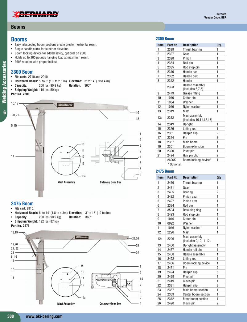
2475 Boom• Fitscart:2910.• Horizontal Reach:6'to14'(1.8to4.3m) Elevation: 3'to17'(.9to5m)• Capacity: 200lbs(90.9kg) Rotation: 360° • Shipping Weight:192lbs(87kg)Part No. 2475
Booms• Easytelescopingboomsectionscreategreaterhorizontalreach.• Singlehandlecrankforsuperiorelevation.• Boomlockingdeviceforaddedsafety,optionalon2300.• Holdsupto200poundshangingloadatmaximumreach.• 360°rotationwithproperballast.
Item Part No. Description Qty
1 2436 Thrustbearing 12 2431 Gear 13 2435 Bearing 24 2432 Piniongear 15 2427 Pinionarm 16 2334 Rollpin 17 3504 Retainingring 18 2423 Rodstoppin 19 1040 Cotterpin 110 0922 Washer 111 1046 Nylonwasher 112 2290 Mast 1
12a 2296Mastassembly(includes9,10,11,12)
13 2460 Uprightassembly 114 2437 Handlerollpin 115 2408 Handleassembly 116 2422 Liftingrod 117 2466 Boomlockingdevice 118 2471 Pin 219 2424 Hairpinclip 620 2469 Pivotpin 121 2419 Clevispin 122 2331 Hairpinclip 323 2367 Mainboomsection 124 2369 Centerboomsection 125 2372 Frontboomsection 126 2420 Clevispin 2
Item Part No. Description Qty.1 2329 Thrustbearing 12 2327 Gear 13 2328 Pinion 14 2334 Rollpin 15 2335 Rodstoppin 16 2346 Handlebar 17 2332 Handlebolt 18 2342 Handle 1
2323 Handleassembly(includes6,7,8)
9 2479 Greasefitting 110 1040 Cotterpin 111 1034 Washer 112 1046 Nylonwasher 113 2319 Mast 1
13a 2352Mastassembly(includes10,11,12,13)
14 2349 Upright 115 2326 Liftingrod 116 2331 Hairpinclip 217 2344 Pin 218 2337 Mainboom 119 2301 Boomextension 120 2320 Pivotpin 121 2424 Hairpinclip 2
2696K Boomlockingdevice* 1
18
5,15
20,21
16,17
14
Cutaway Gear Box
1
2
3
9
4
6
7
8
19
2300 Boom• Fitscarts:2710and2910.• Horizontal Reach:5'to8'(1.5to2.5m) Elevation: 3'to14'(.9to4m)• Capacity: 200lbs(90.9kg) Rotation: 360° • Shipping Weight: 110lbs(50kg)Part No. 2300
2300 Boom
11
12
10
13
13a
Mast Assembly
1
2
14
7
3
6
4
10
11
9
12
12a
Mast Assembly Cutaway Gear Box
2475 Boom
*Optional
Booms
13
www.oki-bering.com

309
6
Welding Accessories
Bernard, AquasolVendor Code: BER, ASW
Wall Mount• WallMountboltstoaverticalsteelcolumnormasonrywall.• Capacity: 200lbs(90.9kg)• Size (HxLxW):16"x16"x7"• (40.64cmx40.64cmx17.78cm)• Mounting Holes: 13/16”(2.06cm)• Weight: 42lbs.(19kg)Part No. 2390
BOOM Mounting System• Boommountsaretherightchoicewhenspaceislimitedontheshopfloororwhenafixedinstallationisdesired.• BothmodelsprovideexcellentstabilityandfitallBernardbooms.
Floor Mount• Floormountboltstotheplatformofatruckorshopfloor.• Capacity: 200lbs.(90.9kg)• Size (HxLxW): 14"x14"x14" (35.56cmx35.56cmx35.56cm)• Mounting Holes: 13/16"(2.06cm)• Weight: 37lbs(16.7kg)Part No. 2380
Booms / Water Soluble Products
EZ Tape™
EZTape™istraditionalaluminumweldingtapethatcanbeusedtosealrootgapswhilepurging,however,werecommendEZZone™Tapebeusedforthispurposetoachievethepurestweld.EZTape™hasmanyotherconventionalusesinthefieldsuchassealingpipeendsfortransporting,sealingductsforheating,airconditioningandrefrigeration,andactingasavaporbarrier.
Part No. SizeEZ Tape™
EZ-T2.0 2"x75'EZ Zone™ TapeEZ-ZT2.5 2.5"x75'EZ-ZT4.0 4"x75'
EZ Wipes™ CanisterEZWipes™allowaweldertoquicklyandeffectivelycleanpipespriortowelding,reducingtheriskofweldcontaminationandincreasingthenumberofpurefinishedwelds.EZWipes™featureaspecializedtwo-sidedcleaningfabric,anabrasivesidetoloosendriedonsurfacecontaminantsandasmoothsidetorevealacleaner,polishedsurface.
Part No. DescriptionEZW-30 30percanisterEZW-70 70percanister
EZ Purge™ PaperAquasol®water-solublepaperandtapeisacostsavingalternativetoconventionalpurgingsystems.Thispaperisusedtodamargonorheliumgasesduringtungsteninertgas(TIG)weldingofsteeloraluminumpipes.Aquasol®water-solublepaperdissolvesinstantaneously.Usewatersolubletapeforfastadhesionofpapertopipe.• ASW-35(.0035"thick)isforuseonpipes4"IDorless.• ASW-60(.0060"thick)isforuseonpipes4"IDorgreater.
Part No. Size35S-11 8.5"x11"500/CA35S-14 8.5"x14"500/CA60S-22 15"x22"250/CA35S-22 17"x22'500/CA35R-9 9"x165'35R-15 15"x165'60R-15 15.5"x165'60R-31 31"x165'Water Soluble TapeWT-1 1"x300'WT-2 2"x300'
www.oki-bering.com