bernardo frankenfeld villela pedras environrc: integrating...
TRANSCRIPT

Bernardo Frankenfeld Villela Pedras
EnvironRC: Integrating collaboration and mobile
communication to offshore engineering virtual reality
applications
Dissertação de Mestrado
Dissertation presented to the Programa de Pós-Graduação
em Informática, of the Departamento de Informática do Centro
Técnico Científico da PUC-Rio, as partial fulfillment of the
requirements for the degree of Mestre em Informática.
Advisor: Prof. Alberto Barbosa Raposo
Rio de Janeiro
September 2015

Bernardo Frankenfeld Villela Pedras
EnvironRC: Integrating collaboration and mobile
communication to offshore engineering virtual reality
applications
Dissertation presented to the Programa de Pós-Graduação
em Informática, of the Departamento de Informática do Centro
Técnico Científico da PUC-Rio, as partial fulfillment of the
requirements for the degree of Mestre.
Prof. Alberto Barbosa Raposo Advisor
Departamento de Informática – PUC-Rio
Prof. Markus Endler
Departamento de Informática – PUC-Rio
Prof. Hugo Fuks
Departamento de Informática – PUC-Rio
Prof. José Eugenio Leal
Coordinator of the Centro Técnico Científico da PUC-Rio
Rio de Janeiro, September 11th, 2015
All rights reserved
Bernardo Frankenfeld Villela Pedras
Graduated in Computer Engineering from Pontifícia Universidade Católica
do Rio de Janeiro – PUC-Rio in 2009.
Bibliographic data
Pedras, Bernardo Frankenfeld Villela
EnvironRC: Integrating collaboration and mobile communication to
offshore engineering virtual reality applications / Bernardo Frankenfeld
Villela Pedras ; advisor: Alberto Barbosa Raposo. – 2015.
90 f. : il. ; 29,7 cm
Dissertação (Mestrado em Informática)–Pontifícia Universidade Católica do
Rio de Janeiro, Rio de Janeiro, 2015.
Inclui bibliografia
1. Informática – Teses. 2. Sistemas colaborativos. 3. Comunicação mobile.
4. Integração mobile. 5. Interação 3D. I. Raposo, Alberto Barbosa. II.
Pontifícia Universidade Católica do Rio de Janeiro. Departamento de
Matemática. III. Título.
CDD: 004

To my parents, Christine and Paulo.

Acknowledgments
First, I would like to thank my family for all the support, love and help during the
time needed to complete this work. I would like to specially thank my sister, Pauline
Meierfrankenfeld, for all the help and dedication during some difficult moments.
A very special thank you to my beloved fiancée, Mayra Calil, for all the love and
incentive. Thank you for understanding and providing me with all the support I needed.
I would also like to thank my advisor, Prof. Alberto Raposo, for doing everything
possible to provide all the needed resources for this work to take place.
Big thanks to my friends of the MorningStar and TecGraf Galilleu team for
providing a friendly environment that made this work possible. I would like to thank
Ismael dos Santos for the many teachings and collaborations that made me the
professional I am today.
Finally, thanks to PUC-Rio and Petrobras for all the assistance given.
Abstract
Pedras, Bernardo Frankenfeld Villela; Raposo, Alberto Barbosa (Advisor).
EnvironRC: Integrating collaboration and mobile communication to
offshore engineering virtual reality applications. Rio de Janeiro, 2015. 90p.
MSc. Dissertation - Departamento de Informática, Pontifícia Universidade
Católica do Rio de Janeiro.
Offshore Engineering visualization applications are, on most cases, very
complex and should display a lot of data coming from very computational intensive
numerical simulations. To help analyze and better visualize the results, 3D
visualization can be used in conjunction with a Virtual Reality (VR) environment.
The main idea for this work began as we realized two different demands that
engineering applications had when running on VR setups: firstly, a demand for
visualization support in the form of better navigation and better data analysis
capabilities. Secondly, a demand for collaboration, due to the difficulties of
coordinating a team with one member using VR. To meet this demands, we
developed a Service Oriented Architecture (SOA) capable of adding collaboration
capabilities to any application. The idea behind our solution is to enable real-time
data visualization and manipulation on tablets and smartphones. Such devices can
be used to help navigate the virtual world or be used as a second screen, helping
visualize and manipulate large sets of data in the form of tables or graphs.
Furthermore, we want to allow collaboration-unaware application to collaborate
with as little reworking of the original application as possible. Another big
advantage that mobile devices bring to the engineering applications is the capability
of accessing the data on remote locations, like on oil platforms or refineries, and so
allowing the field engineer to check the data or even change it on the fly. As our
test application, we used ENVIRON, which is a VR application for visualization of
3D models and simulations developed in collaboration with a team from the
Institute Tecgraf of PUC-Rio. We added this solution to ENVIRON and it was
tested with an experiment and during a review process of Offshore Engineering
using VR Setups (Power wall and CAVE).
Keywords
Collaboration; Mobile-communication; Mobile-Integration; 3D-Interaction
Resumo
Pedras, Bernardo Frankenfeld Villela; Raposo, Alberto Barbosa (Orientador).
EnvironRC: Integrando colaboração e comunicação móvel a aplicações de
Engenharia Offshore em ambientes de realidade virtual. Rio de Janeiro,
2015. 90p. Dissertação de Mestrado - Departamento de Informática, Pontifícia
Universidade Católica do Rio de Janeiro.
Aplicações de visualização de Engenharia Offshore são, na maioria dos casos,
muito complexas e devem ser capazes de representar muitos dados vindos de
simulações numéricas computacionalmente intensivas. Para ajudar a melhor
analisar os resultados, visualização 3D pode ser usada em conjunto com ambientes
de Realidade Virtual (RV). A ideia principal desse trabalho começou quando
reconhecemos duas demandas que aplicações de engenharia tinham ao rodar em
ambientes RV. Primeiramente há uma demanda para suporte à visualização na
forma de melhorias na navegação e na capacidade de analisar os dados. Em segundo
lugar, há também uma demanda por colaboração devido às dificuldades de
coordenar uma equipe com um dos membros utilizando RV. Para atender estas
demandas, nós desenvolvemos uma arquitetura orientada a serviços (SOA) capaz
de adicionar colaboração a qualquer aplicação. A ideia por trás da nossa solução é
permitir a visualização de dados em tempo real através de tablets e smartphones.
Estes dispositivos móveis podem ser usados para ajudar a navegar o mundo virtual
ou serem usados como uma segunda tela, ajudando a visualizar e a manipular
grandes conjuntos de dados na forma de tabelas ou gráficos. Além disso, queremos
adicionar as funcionalidades de colaboração a uma aplicação com o mínimo
possível de alterações na aplicação original. Outra vantagem importante que
dispositivos móveis adicionam a aplicações de engenharia é a capacidade de acessar
os dados em locais remotos, como plataformas de petróleo e refinarias, e assim
permitindo ao engenheiro de campo manipular os dados no local de trabalho. Como
aplicação teste, utilizamos o ENVIRON, que é uma aplicação de RV para
visualização de modelos e simulações de engenharia, desenvolvida em conjunto
com a equipe do Instituto Tecgraf da PUC-Rio. Adicionamos esta solução ao
ENVIRON e testamos com um experimento e durante o processo de análise de
Engenharia Offshore usando ambientes RV (PowerWall e CAVE).

Palavras-chave
Sistemas colaborativos; Comunicação mobile; Integração mobile; Interação 3D

Summary
1 Introduction........................................................................................................... 12
1.1 Motivation ..................................................................................................... 13
1.2 Document structure........................................................................................ 14
2 Related Work ........................................................................................................ 16
2.1 Immersive applications and environments ...................................................... 16
2.2 Offshore Engineering applications ................................................................. 18
2.3 Collaboration ................................................................................................. 20
3 Methodology ......................................................................................................... 22
3.1 VR setup support experiment ......................................................................... 22
4 Architecture .......................................................................................................... 24
4.1 Requirements................................................................................................. 24
4.2 Overview ....................................................................................................... 25
4.3 Communication channels ............................................................................... 26
4.4 Collaboration ................................................................................................. 27
4.4.1 Collaboration Sessions ........................................................................... 27
4.4.2 Collaboration Manager ........................................................................... 28
4.5 Use-Scenarios ................................................................................................ 30
4.5.1 Mobile Integration ................................................................................. 31
4.5.2 Single Mobile / Multiple instances ......................................................... 33
4.5.3 Multiple Mobile / Remote users ............................................................. 34
5 AppRC Implementation ......................................................................................... 36
5.1 MULE ........................................................................................................... 36
5.2 Communication channels ............................................................................... 39
5.2.1 File input channel................................................................................... 40
5.2.2 TCP/IP Socket input channel .................................................................. 40
5.2.3 Web service input channel...................................................................... 41
5.2.4 Mobile WebService input channel .......................................................... 42
5.3 Extension Points ............................................................................................ 43
5.3.1 Mobile Application Service .................................................................... 44
5.3.2 Application Proxy .................................................................................. 45
5.4 GUI ............................................................................................................... 46
6 EnvironRC Implementation ................................................................................... 48
6.1 Environ.......................................................................................................... 48
6.2 Extension Points ............................................................................................ 50
6.2.1 Mobile Environ Service ......................................................................... 50
6.2.2 Environ Proxy ........................................................................................ 51

6.3 EnvironMobile .............................................................................................. 52
6.3.1 Visualization parameters ........................................................................ 53
6.3.2 Navigate the model structure .................................................................. 54
6.3.3 Navigate the virtual world ...................................................................... 55
6.3.4 Manipulate annotations .......................................................................... 56
6.3.5 Manipulate engineering data................................................................... 57
6.3.6 Take snapshots ....................................................................................... 58
6.3.7 Manipulate the collaboration session ...................................................... 59
6.4 EnvironScript ................................................................................................ 60
7 Results .................................................................................................................. 62
7.1 Experiment .................................................................................................... 62
7.1.1 Experiment preparation .......................................................................... 62
7.1.2 Experiment execution............................................................................. 66
7.1.3 Results analysis ...................................................................................... 67
7.2 EnvironRC in NVC ....................................................................................... 70
7.2.1 BSR Project ........................................................................................... 71
7.2.2 Review process in NVC ......................................................................... 72
7.2.3 Performance ........................................................................................... 76
8 Conclusion ............................................................................................................ 78
9 Bibliography ......................................................................................................... 80
A Appendix .................................................................................................................. 83
A.1 Manual básico Environ e EnvironRC .................................................................. 83
A.2 Descrição das Tarefas 1 e 2................................................................................. 85
A.3 Termo de Consentimento .................................................................................... 86
A.4 Questionário pré-uso .......................................................................................... 87
A.5 Questionário pós-teste ........................................................................................ 88
A.6 Roteiro de entrevista semi-estruturada ................................................................ 90

List of Figures
Figure 1 - Environ running on a cave setup at Cenpes - Petrobras .................................. 16
Figure 2 - Offshore Engineering project layout .............................................................. 19
Figure 3 - Full Architecture Overview ........................................................................... 26
Figure 4 - Mobile integration use-scenario .................................................................... 32
Figure 5 - Simple mobile integration example ............................................................... 32
Figure 6 - Single mobile/ many instances ...................................................................... 33
Figure 7 - Single Mobile / Multiple instances ................................................................ 34
Figure 8 - Multiple mobile / remote users ...................................................................... 35
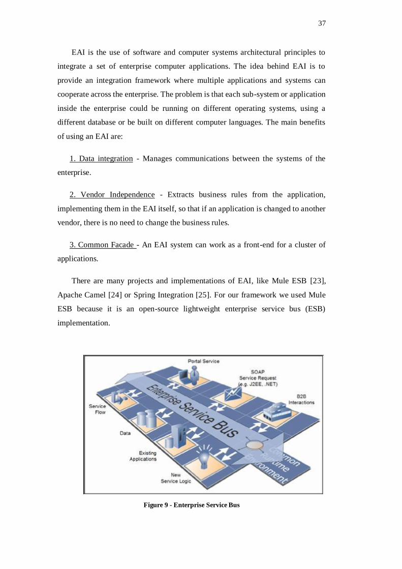
Figure 9 - Enterprise Service Bus .................................................................................. 37
Figure 10 - Mule flow overview .................................................................................... 38
Figure 11 - AppRC with Mule ESB ............................................................................... 39
Figure 12 - Sending commands via socket ..................................................................... 41
Figure 13 - Web service example with JAX-RS ............................................................. 42
Figure 14 - Extension points overview .......................................................................... 43
Figure 15 - Mobile application service extension point .................................................. 44
Figure 16 - Mobile application service code example .................................................... 45
Figure 17 - Basic AppRC GUI ...................................................................................... 47
Figure 18 - Environ running offshore simulation ........................................................... 49
Figure 19 - Mobile service extension use ....................................................................... 51
Figure 20 - Environ mobile visualization settings .......................................................... 53
Figure 21 - Manipulate the model structure ................................................................... 54
Figure 22 - Virtual world navigation ............................................................................. 55
Figure 23 - List of annotations ...................................................................................... 57
Figure 24 - Manipulate engineering data ....................................................................... 58
Figure 25- Mobile snapshot ........................................................................................... 59
Figure 26 - Collaboration control .................................................................................. 60
Figure 27 - EnvironScript configuration XML ............................................................... 61
Figure 28 - Time to complete tasks................................................................................ 68
Figure 29 - Post-test results ........................................................................................... 69
Figure 30 - BSR illustration model ................................................................................ 71
Figure 31 - Two BSR overview ..................................................................................... 72
Figure 32 - Powerwall setup on NVC ............................................................................ 73
Figure 33 - EnvironRC on BSR Review process ............................................................ 74
Figure 34 - PowerPoint Slide using EnvironScript ......................................................... 75
Figure 35 - Example BSR Environ script ....................................................................... 75
Figure 36 - Mobile on BSR review ................................................................................ 76

12
1 Introduction
Offshore engineering systems require many multi-disciplinary specialists.
Offshore engineering visualization applications are, in most cases, very complex
and should display a lot of data coming from very computational intensive
numerical simulations. To help analyze and better visualize the results, 3D
visualization can be used in conjunction with a Virtual Reality (VR) environment.
ENVIRON [1] is one such application developed in collaboration with a team from
the Institute Tecgraf of PUC-Rio and was the focus of our study.
The main idea for this work began as we realized two different demands that
engineering applications had when running in VR setups: demand for visualization
support in the form of better navigation and better data analysis capabilities and
demand for collaboration.
First, since the models being visualized originated from large numerical
simulations, we noticed the need for a better user-interface to allow the user to
visualize large amounts of data, without disturbing the virtual world representation
on the main VR screen. Engineering data are mostly represented by large tables of
numbers and graphs, which are not suited for display in VR environments.
Second, we realized that having an immersive VR environment brought real
benefits for the review process of large simulations [2]. However, a problem
remained; it was hard for the user in the VR setup to communicate and make his
observations useful. A better way to collaborate and produce useful data from the
VR sessions was needed. A further motivation for collaboration comes from the
inherited multi-disciplinary aspect of offshore engineering. To analyze the results,
many different specialists (mostly geographically separated) need to work together
on the same model.
Therefore, to solve these problems, we developed a Service Oriented
Architecture (SOA) capable of adding external communication and collaboration
capabilities to any application. The idea behind our solutions is to enable
collaboration-unaware [3] [4] applications to collaborate with as little reworking of
the original application as possible. Collaboration-unaware applications are
13
originally developed to be single user applications, but may be used collaboratively
by means of an external support system. This external support system may be an
application sharing system or a GUI event multiplexing system. In both cases the
applications do not explicitly support collaboration; they are implemented as single
user applications. This is important since, in our case, the applications developed
for OE projects fits in this type.
In addition, to solve the user-interface problem, we used the added
communication mechanism of the application to enable real-time data visualization
and manipulation with tablets and smartphones. Such devices can be used to help
navigate the virtual world or be used as a second screen, helping visualize and
manipulate large sets of data in the form of tables or graphs. Another big advantage
that mobile devices bring to the engineering applications is the capability of
accessing the data in remote locations, like on oil platforms or refineries, and so
allowing the field engineer to check the data or even change it on the fly.
We have developed and tested the proposed architecture with an application
called EnvironRC (Environ Remote Control). EnvironRC is an application that adds
the benefits of integration with mobile devices, visualization support and
collaboration to ENVIRON. We opted to demonstrate the benefits of using
EnvironRC in VR session with an experiment. Furthermore, we present a real world
use of the collaboration aspect of EnvironRC to help offshore engineers review
simulation results.
Furthermore, we developed a generic and extensible version of EnvrionRC,
called AppRC [5]. AppRC is a framework that can be extended to be used by any
other application that wishes to add external communication and collaboration
functionalities.
1.1 Motivation
This work started as a part of the ENVIRON development and the demands we
recognized while running ENVIRON in many VR environments in NVC
(Collaborative Visualization Center) at CENPES/Petrobras. Environ is an

14
application capable of displaying in VR the results of offshore engineering
applications as 3D rendered scenarios.
Our solution started as a simple solution to integrate mobile navigation to
ENVIRON. After a while being developed only as part of ENVIRON, it grew to
become a generic framework to integrate external communications to any existing
application, called AppRC [5].
Taking inspiration on the extensive work done in the field of Collaboration [2],
we decided to incorporate to our solution a downsized version of the CEE-
collaboration structure.
The motivation for this work comes from the benefits associated with enabling
Environ (or any application) running in a virtual environment to efficiently
collaborate in Real-time with other users in different environments (including
normal Desktop, Tablets, cell phones etc.).
1.2 Document structure
The sequence of chapters of the present work is organized as follows.
Chapter 2 presents the related works that inspired the creation of our
collaboration solution, AppRC. It also serves as a theoretical basis of this work,
outlining and explaining the three main areas of interest: Collaboration, Offshore
Engineering and Immersive applications in VR environments.
In Chapter 3 we define our experiment methodology, describing why we chose
to run the experiment and the specific details and documents of the experiment.
In Chapter 4 we explain the overall architecture of our solution. Beginning by
defining the requirements our solution should meet. After that, we give an overview
of the architecture and describe how the components are connected through the
communication channels. We then explain the collaboration aspect of the
architecture and finally we define 3 main use-scenarios that serve as examples of
how our architecture works.
15
Chapter 5 and 6 are dedicated to showing how our solution was implemented.
We divided the implementation in two steps. Chapter 5 is about the implementation
of AppRC, the generic solution that can be used by any application. We explain
how it is structured and how the integration of new applications is achieved by using
what we called “Extension Points”. Chapter 6 is about the implementation of
EnvironRC, a specific use of the AppRC solution to be used with Environ and the
main focus of our study. We explain three implementation challenges in further
detail; first, we discuss how we used each “Extension Point” of AppRC, then we
explain the implementation of EnvironMobile, a IOS mobile application and
finally, the implementation of the small helper application called EnvironScript.
In Chapter 7 we present our results using the entire presented solution both with
an experiment and with the use in a real-world scenario. We used EnvironRC to
help in the review process of a big offshore project called BSR. We describe in
further details the challenges and the benefits that EnvironRC brought to the
offshore engineers.
Finally, we present the conclusions and discuss possible future works in Chapter
8.

16
2 Related Work
This chapter is divided in three subsections; immersive environments, offshore
engineering and collaboration. These sections represent the main areas of interest
of our work and we will use each section to explain in more detail what they are
and how they apply to this dissertation.
2.1 Immersive applications and environments
The goal of immersive applications is to provide the user with a life-like
experience and immerse the user in the virtual environment (Figure 1). Real-Time
3D applications are the main type of application to achieve this goal. Real-time 3D
applications use different techniques to achieve the immersion, including: best
possible visual output, stereoscopic 3D for depth perception, precise and immediate
response to the user inputs, among others.
Figure 1 - Environ running in a cave setup at Cenpes - Petrobras
Many different immersive environments were build. Some of the most well-
known are “Powerwalls”, CAVE [6] and L-Shape displays. Many engineering
applications can benefit from the use of virtual environments. These environments
can be used for many tasks, for example: Immersive visualization for training

17
purposes, evaluation of Virtual Environments on human scale, visualization of large
amount of Data, visualization of large fields as 3D environment.
VR visualization technologies enhance the content knowledge within any
engineering design activity. Used in conjunction with collaboration, VR
visualization provides valuable insights for better Decision Support with risk
mitigation.
While there are huge benefits of using virtual environments, many problems
arise when running complex applications in an engineering virtual environment,
especially applications that were not built from the ground up with such
environments in mind (as is often the case).
There are many applications that utilize mobile devices to enhance the VR
experience. Most of them focus on implementing efficient ways to navigate or to
interact with the 3D world. Medeiros [7] presents an efficient way to navigate in an
immersive environment with the use of a tablet. Further discussions and concepts
for navigation with mobile devices can be found in [8], [9] and [10].
Most implementations of navigation functionalities in VR systems rely on the
VRPN (Virtual-Reality Peripheral Network) [11], which is a device-independent
and network-transparent system for accessing virtual reality peripherals in VR
applications. VRPN provides a communication standard for developers who want
to utilize different sensors as inputs to their application. Although the VRPN
framework is widely adopted as the communication channel for navigation input
information, it does not provide a good way to handle other kinds of information,
like symbolic input, large amount of data or more complex data structures like
photos or videos.
LVRL (Lightweight Virtual Reality Libraries) [12] is a way to port an
application to a VR system. It also defines an input communication channel that is
based on the VRPN implementation, leaving some room for the developer to
implement custom channels. Since the main goal of LVRL is to port the entire
application, requiring reworking of the application to use the LVRL, there is no
concern in keeping the communication channel generic.

18
There are some proprietary mobile application development systems that
integrate a sort of framework to manage the messages from the mobile application
to a server application. Flick [13], for example, provides a framework restricted for
testing and debugging the server-client communication. The Maximo Integration
Framework (MIF) [14] is defined as a framework that provides web services and
Service Oriented Architecture (SOA) technologies to support application services
and coordination between enterprise systems such as synchronization and
integration of data between applications. It is a specific framework that handles data
transfers to IBM’s Maximo system. Although restricted to the Maximo system,
some solutions were developed to integrate the SOA architecture of MIF with
mobile devices [15], [16].
2.2 Offshore Engineering applications
Offshore engineering (OE) systems require many multi-disciplinary specialists,
involving the areas of structural calculus, meteo-oceanography (currents, waves and
wind forces), hydrodynamics, risers (rigid or flexible steel pipes for carrying oil
from the well in subsurface up to the production unit), mooring systems, submarine
equipment, seabed foundations and Geologic/Geotechnical risk assessment. Deep-
water production systems, including floating production units (platforms or ships)
and all the equipment playing a part in the production process, are some of the
objects of interest for offshore systems. (Figure 2)

19
Figure 2 - Offshore Engineering project layout
Due to their huge complexity, OE projects are divided into smaller interrelated
subprojects where each one deals with an abstract representation of the others.
Because decisions are interdependent, collaboration is a key point in this area. Each
team activity or new decision can affect other activities
The changes to a parameter of one of the subprojects could affect all the other
subprojects. For example, changes to the environmental conditions (wave, wind or
currents) will affect the simulation of the platforms position and this new movement
would propagate to all risers and, therefore, should be carefully analyzed to
guarantee compatibility with the structural balance of the production unit.
To help integrate all simulators and make sure all simulation results from the
intermediate steps in the workflow are consistent with each other, a data format is
used called GXML [17] that is able to store all the data coming from different
sources.
To account for all variables and parameters, OE applications are typically very
computational intensive and run large amounts of numerical simulation. Some of
these simulations may require huge computational efforts to be processed, even for
powerful computational grid clusters. Another challenge for OE applications is
related to the visualization of such results. Visualization should be as precise as

20
possible in order to provide the user a full understanding of the results of the
simulation.
As already discussed in section 1.1, Offshore applications were part of the focus
of our work because the stand to benefit a lot from the integration of our solution.
2.3 Collaboration
Collaborative systems should not only allow multiple users to interact with
shared objects but also to communicate and to coordinate their actions.
Collaboration may be seen as the combination of communication, coordination and
cooperation [18]. Communication is related to the exchange of messages and
information among people. Coordination is related to the management of people,
their activities interdependencies and the used resources. Cooperation is the
production of common artifacts taking place in a shared space through the
operations available to the group.
Briggs [19] defines many key concepts of collaboration engineering, involving
team goals and how to define the objective of a collaboration work. For our work,
we are especially interested in the concepts he defined as Pattern of Collaboration,
Capability, Constraints and Rules. We use the pattern of collaboration as our
collaboration session types (section 4.4), Capability, constraints and rules are used
to dictate the permissions within the collaboration session.
As mentioned before, the messages exchanged should always try to achieve the
goal of a Collaborative system (Communication, coordination and cooperation). In
the broader approach of CEE [2], a special attention was given to the
communication between users (with the implementation of a video conference
channel). We do realize the importance of informal communication between the
users as a way to enhance team awareness [20], but we decided to leave the informal
communication outside the scope of the project, since there are already many ways
to achieve this communication.
As discussed earlier, The AppRC solution started as a specialization of the much
bigger and generic collaboration environment called CEE. The focus of CEE was

21
to create a collaboration framework where many different users can work at the
same time across different platforms. However, CEE requires a network and server
infrastructure, which is not suited for the integration of mobile devices.

22
3 Methodology
As mentioned in Chapter 1, we have two main goals with this dissertation:
enable engineering visualization applications to be used in VR setups and add
collaboration. Therefore, we decided to test both aspects of this work with two
different methodologies.
To test the VR setup support, we decided to run an experiment with users to
help determine the impact on the immersion experience while using a tablet
connected to the main visualization system.
For the collaboration aspect of our solution, we present a real-world use of
EnvironRC to help offshore engineers analyze the results of many simulations in a
presentation setup. Further studies and a complete case-study of the collaboration
aspect are left as future works.
3.1 VR setup support experiment
We chose to perform an experiment because of the nature of the problem we
were trying to analyze. The user experience when using a CAVE is subject to many
different aspects, such as, time needed to complete tasks, usability, user experience,
immersion perception, among others. By running a controlled experiment, we will
try to analyze qualitative and quantitative aspects of this experience.
The objective of our experiment was both descriptive and explanatory. We
wanted to describe how the users interacted with the system and what their thoughts
were. At the same time, we wanted to examine if the use of a tablet device in VR
setups had positive impact in the VR session, both in terms of time needed to
complete a task and user experience.
We recruited participants for the experiment that had familiarity with
computers, had experience with complex three dimensional applications such as
games and 3D modeling software and had experience using VR setups. The
decision to recruit only users with experience in VR setups was made to avoid large
distinctions in execution time. VR setups can be very confusing and take a large
amount of time for a new user to get used to. So, by having only experienced users,
we can avoid problems with training bias.

23
The experiment consisted of the users performing two tasks in a CAVE VR
setup. Both tasks were performed first with Environ (without EnvironRC) and
afterwards with EnvironRC. To ensure that all users had the same experience with
both EnvironRC and Environ, we conducted a training session before the
experiment. In the training session, the users had unlimited time to try both
applications and ask questions.
To collect the data, we used different techniques:
Pre-test question form.
Post-test question form.
Time to perform each task.
Semi-structured interview.
The pre-test form was used mainly to select the participants’ profile. Post-test
question form and the time to perform each task were used as a quantitative
measurement of each user performance and experience. The semi-structured
interview was designed to collect qualitative information about the use of the
system and to help describe the experience in further detail.
Further details on how the experiment was conducted and the results are
described in section 7.1.

24
4 Architecture
4.1 Requirements
As mentioned before, there are two main goals for this project. First, we want
to provide a better user interface for users in VR environments. Second, we want
them to be able to collaborate with remote users and exchange engineering data in
real time.
To achieve these goals, we set the following requirements on our solution:
The solution should be generic and extensible
o Although the focus of this work is to study our solution used with
Environ, we want the solution to be as generic and extensible as
possible to enable its use with other applications with little extra
work.
The solution should require minimum reworking of the original
application.
o The original application (in our case, Environ) should not be
rewritten. All the collaboration and communication layers
should be external to the application itself.
The solution should add very low overhead.
o While running the original application with the added benefits of
our solution, there should be very little performance impact.
The solution should be responsive and interactive.
o The communication between all the users collaborating with
different devices should be fast and always responsive.
The solution should have a minimalistic interface.
o The interface should be very small and non-intrusive, but should
give the user feedback of the current status of the collaboration.

25
The solution should be portable.
o There should not be any hardware or software requirement to run
the collaboration solution. It should run on any simple machine
without any extra support (like application servers).
The only requirement we set on the user-application (in our case, Environ),
is that the application should have some way to receive commands from an outside
source. We left open what exactly this command-passing mechanism is, since it
depends heavily on many technical aspects of the application, such as, programing
language, platform and internal architecture.
4.2 Overview
In this section, we present the architecture overview of the generic AppRC
solution. EnvironRC, the specific implementation of AppRC for the Environ
application follows the same architecture and the specific details of its
implementation will be discussed in chapter 6.
The goal of our architecture is to integrate external communications and enable
collaboration in a collaboration-unaware application. Therefore, our architecture is
resolved around supporting many instances of the application running on multiple
machines and devices.
Our solution is divided in three main components.
1. AppRC Server
2. AppRC Client
3. Mobile Application
AppRC Server works as the central HUB of all communications. All users are
required to communicate through the Server. It also manages all collaboration
aspects including users and permissions. The server receives (via the Collaboration
BUS) all messages and routes it to the corresponding receivers. (Figure 3)

26
Figure 3 - Full Architecture Overview
AppRC Client works as a proxy of the main server running on a different
machine. It only passes the messages along to the main server. For the collaboration
BUS, there is no distinction between an instance of the application running on a
same machine or on a remote device.
Each application instance is both an Inbound and Outbound Endpoint (defined
in more detail in section 5.1), capable of receiving and sending messages. The
Mobile Proxy works almost the same as an instance of the application, with the
important distinction of being exclusively an Inbound Endpoint. The reason for this
decision is so that the mobile application can only request information it needs, and
does not have to always listen to incoming messages.
4.3 Communication channels
AppRC Server has four different kinds of possible external communication
channels for input messages:
Basic text file
Socket
WebService
Mobile communication
27
AppRC Server is responsible for passing the commands received by each input
channel to the corresponding application instance. The connection between AppRC
Server/Client and the application instance is done, in the case of EnvironRC,
through a local socket connection. For the generic AppRC, this connection
implementation is left open because it depends on specific connection capabilities
of the application. This communication channel will be presented in more detail in
Section 5.3, where we discuss the implementation of the Extension Points.
4.4 Collaboration
In this section we discuss the collaboration aspect or our architecture. First, in
the following section, we define the concept of “Collaboration Session” and the
rules governing each type of session. Then, in section 4.4.2, we describe the
implementation of the Collaboration BUS and Collaboration Manager in further
detail. Furthermore, we discuss how the collaboration session is managed using
control messages.
4.4.1 Collaboration Sessions
In order to manage the message exchange between all the participants of a work
session, some rules must be defined to stablish a collaboration session. A
collaboration session represents the type of collaboration the users should do. As
was the case with CEE collaboration framework, we anticipate three kinds of
collaboration sessions.
Informal
Classroom
Lecture
In an Informal Session each participant can send and receive messages from
any other participant without any restrictions. The Collaboration Manager only
passes the messages to all other participants of the session. In a Classroom session
28
one specific participant, the instructor, acts as a coordinator of the session which
means that he/she is the only one able to send messages to other participants. The
instructor is also allowed to pass control of the collaboration session among
participants. Users can also request the coordination role to the current coordinator
who can accept or reject the request. The Lecture session has a speaker that acts as
the coordinator of the session, with the same characteristics of a Classroom session.
However, in this type of session there is no switch of control between the
coordinator and participants. At any time, a user can leave the session, for doing
some private work, and join the session in later time.
4.4.2 Collaboration Manager
The Collaboration manager is responsible for keeping track of all activity on the
connected endpoints, and synchronize the information accordingly.
The main component of the collaboration manager is the Collaboration BUS.
The Collaboration BUS provides both synchronous and asynchronous
communication to the instances of the application. The Collaboration manager is
the module with which each instance of the application can interact.
The Collaboration manager is responsible for passing messages along the
collaboration BUS. There are two main kind of messages: First, the messages that
need to be passed and processed by the application instances. These messages
represent commands and instructions that an application instance can read and
execute. The second kind of messages is what we call “control messages”. These
are messages that each user can send to interact with the collaboration session.
These messages represent control commands such as asking the collaboration
manager for permission to join a working session, message to add a new application
instance to the session or to disconnect a user from the session.
We defined eight control commands to manipulate the collaboration
environment.

29
USE_APP(ID) Used to select the default application instance
CREATE_APP(ID) Used to create a new application instance
START_APP(ID) Used to run a new application instance
CLOSE_APP(ID) Used to shut down and remove an application
instance
BROADCAST_BEGIN signals that all messages should start being
broadcast
BROADCAST_END signal the end of a message broadcast
CHANGE_SESSION_TYPE(Type) Used to change the current
session type (Informal, classroom or lecture).
REQUEST_CONTROL used in classroom sessions to control and
start sending update commands to other users.
As already discussed in section 4.4.1, we defined three types of collaboration
sessions. In order to maintain the restrictions and rules of each collaboration session
type, we defined two types of users: Manager and Participant. Every time the
collaboration manager receives a new control message, it first checks if the sender
of the message has the required permission to perform the control operation under
the current collaboration session type.
To illustrate the use of the control commands and the permission restrictions,
we will use an example scenario: three application instances running under the
classroom session type. Application number one is the manager of the session and
applications 2 and 3 are setup as participants. A possible sequence of messages
received by the collaboration manager:
1. Application 1 USE_APP(App2)
2. Application 1 commands to application 2 only
3. Application 1 BROADCAST_BEGIN

30
4. Application 1 Commands to all Apps
5. Application 1 BROADCAST_END
6. Application 1 commands to application 2 only
7. Application 2 CHANGE_SESSION_TYPE(Informal)
8. Application 3 try to send command to app 2
9. Application 1 CHANGE_SESSION_TYPE(Informal)
10. Application 3 try to send command app 2
Since Application 1 is the manager of the classroom session, it starts by sending
a control command to tell AppRC that Application 2 is the default receiver of any
message. It then sends some commands to Application 2 (as the default). On item
3, Application 1 starts broadcasting its messages to all apps, ending on message 5.
After the broadcast is over, the messages are again sent to the default application as
seen on item 6. After that, Application 2 tries to request a change in the session type
to informal. This request results in an error since Application 2 is not the manager
of the session and the message is ignored. Next, in item 8, Application 3 tries to
send commands to the default application. This also results in an error since the
session type is defined as classroom and only the manager can send messages.
Finally, on item 9, Application 1 successfully changes the collaboration session
type to informal allowing Application 3 to send the command to Application 2 on
item 10.
4.5 Use-Scenarios
We studied three main use-scenarios to demonstrate the benefits of our
solution. We chose these scenarios as they represent real world situations and reflect
the benefits of adding our solution to engineering applications running in VR
setups. In each scenario, we identify the main problem the application has when
running in VR and how our solution should solve it.

31
Scenario 1 – Mobile Integration
Scenario 2 – Single Mobile / Multiple instances
Scenario 3 – Multiple Mobile / Remote users
In the next sections, we will discuss each of these scenarios in more detail, the
motivation behind them and how our architecture is implemented.
4.5.1 Mobile Integration
The integration of mobile functionality is a new demand for many different
kinds of applications and services. Nowadays it is almost expected of an application
or a service to have some kind of mobile integration. The first kinds of services to
utilize mobile platforms were, for the most part, related to mobile phones, social
networks or media playback. But with the computational power of current smart
devices, a lot of other kinds of applications can utilize the smart devices to enhance
its functionalities. There are a lot of benefits that a mobile device can bring when
integrated to an application. The first one is the obvious gain in mobility. No longer
does the user need to be on a desktop inside an office to access or manipulate the
data. A second benefit are the included sensors present in most smart-devices.
Sensors like GPS Location can, for instance, add important usability information to
the application so that it can respond according to the user’s location. Most smart
devices also have sensors like accelerometers and multi-touch screens that can help
interact with the application, helping to navigate in a 3D-world, or to see large
amounts of data, for example.
We are especially interested in the use of mobile devices to aid the visualization
of engineering data and simulations. Many applications and simulators have been
developed over the years for traditional desktops and/or clusters. It is still
impossible to run such simulations or applications on a mobile device as a
standalone application because of performance issues, and even if it were possible
to run entire simulations on smart devices, it wouldn’t be the best way to do it
because all the generated data must be stored and centralized in databases or servers,

32
and it wouldn’t be practical to transfer such large amounts of data for each
simulation. So, mobile devices should be used to add its benefits to an existing
application or simulator, creating a collaborative environment between the main
application (running all the heavy work) and different connected mobile devices.
This situation illustrates the main problem we try to address in this first scenario.
How to build a collaborative environment between an existing application and
mobile devices with minimum reworking of the existing application?
Figure 4 - Mobile integration use-scenario
For this scenario, we need only a main computer running the engineering
application and a Mobile device that can communicate and interact with the main
application. (Figure 4)
Figure 5 - Simple mobile integration example
As shown in Figure 5, the architecture is very simple. We do not need any kind
of proxy client and the communication can occur directly between the application
and the mobile device. According to Scenario 1, the developer of the application
can integrate mobile communication to an existing application without worrying
about the communication and connection code directly.

33
4.5.2 Single Mobile / Multiple instances
We built this scenario around the idea of having a Powerwall setup. Powerwalls
are typically very large displays with massive resolution, and so, capable of
displaying many contents at the same time. As most applications were not built with
such large resolutions in mind, the most effective way to use the benefits of a
Powerwall visualization setup is to open many instances of the application at the
same time. Each instance using a part of the full Powerwall screen enabling the user
to view all instances simultaneous side by side and compare and analyze the results.
Another instance of this is use-scenario in a VR environment is when the user
has multiple VR applications running in background, each of them with a different
visualization model. This typically happens in CAVE setups, as each model has to
be loaded and properly setup for visualization, a multi-model visualization, where
the user is able to change between models by running multiple instances of the
application in background.
Figure 6 - Single mobile/ many instances
Many instances of the application running simultaneous on the same computer
brings new challenges. There is now a need to coordinate the different instances of
the application on top of managing the collaboration and messages between them.
It is also important for the user to be able to broadcast messages to all instances of
the application. A representation of this scenario can be seen in Figure 6.

34
In Figure 7, we can see how this scenario is represented using our architecture.
Here we need the AppRC Server to be running with the collaboration BUS to
manage the communication and route the messages to the corresponding
application instances.
Figure 7 - Single Mobile / Multiple instances
4.5.3 Multiple Mobile / Remote users
This scenario represents the most complete use of our solution. It encapsulates
many different uses of the collaboration infrastructure. (Figure 8)
It represents for instance the use of the application for a presentation setting,
where there are many models being presented in the main screen and each viewer
of the presentation has a mobile device and can request on-demand specific details
of the main model.

35
Figure 8 - Multiple mobile / remote users
Another use-scenario is during a review process of a model. Sometimes not all
the participants are co-located for the presentation. This is especially interesting for
offshore engineering applications due to its inherited multi-disciplinary aspect. To
analyze the results, many different engineers (mostly geographically separated)
need to work together on the same model. The main review process occurs in the
main visualization environments while remote users can join in and collaborate with
the working session.
Here we need the remote machine to run the AppRC Client and connect it to the
running session of the AppRC Server. The connection of AppRC Client (running
on a remote machine) and AppRC Server (running on the main visualization
machine) is done through a direct socket connection. The fact that there is a remote
user running AppRC Client does not affect the collaboration session. For all
collaboration participants, all other participants are accessible through the same
means (collaboration BUS).

36
5 AppRC Implementation
In this chapter, we will explain how we implemented AppRC and the concept
of Extension Points. The implementation of EnvironRC and how, using the
Extension Points concept, we were able to create a solution for Environ application
will be discussed in chapter 6.
AppRC was developed in Java as a Netbeans Platform application using Mule
ESB [23]. It is designed to have a simple user interface for basic monitoring and
controlling different communication channels.
Another important aspect of AppRC is its support for managing multiple
instances of the application running at the same time. This functionality is very
important when running an application on very large displays for example, as it
allows the user to manipulate from a single source, multiple instances of the
application, providing an efficient way to compare simulation results or data. To
achieve this goal, we adopted the concept of application instances session. Each
session can run a single instance of the application and the user can create and
manage multiple sessions.
In the next sections, we will discuss the implementation of the main features of
AppRC, starting with a discussion of how we used MULE to handle the incoming
communications. After that, in section 5.2, we describe in further detail how each
communication channel works. In section 5.3 we discuss the concept of extension
points and finally in section 5.4 we show the AppRC user interface and some
usability examples.
5.1 MULE
The internal architecture of our solution uses the concept of Service Oriented
Architectures (SOA) in the form of Mule ESB implementation. We use the benefits
of SOA to build a communication bus inside our framework so that the input
services can exchange message with the base application service. This section
describes the concept of an EAI (Enterprise Application Integration) and the Mule
ESB implementation.
37
EAI is the use of software and computer systems architectural principles to
integrate a set of enterprise computer applications. The idea behind EAI is to
provide an integration framework where multiple applications and systems can
cooperate across the enterprise. The problem is that each sub-system or application
inside the enterprise could be running on different operating systems, using a
different database or be built on different computer languages. The main benefits
of using an EAI are:
1. Data integration - Manages communications between the systems of the
enterprise.
2. Vendor Independence - Extracts business rules from the application,
implementing them in the EAI itself, so that if an application is changed to another
vendor, there is no need to change the business rules.
3. Common Facade - An EAI system can work as a front-end for a cluster of
applications.
There are many projects and implementations of EAI, like Mule ESB [23],
Apache Camel [24] or Spring Integration [25]. For our framework we used Mule
ESB because it is an open-source lightweight enterprise service bus (ESB)
implementation.
Figure 9 - Enterprise Service Bus

38
ESB is considered the basis of SOA (Service Oriented Architecture) because it
provides the required technology to realize the benefits the Service Orientation has
to offer. The structure of an ESB is, as its name suggests, an integrated BUS that
manages communication between services and applications inside the enterprise.
The BUS has a shared message format and needs adapters to translate the message
from the BUS to each application or service (Figure 9). Furthermore, ESB provides
a common platform to manage security, transformations, message forwarding,
transactions and monitoring. ESB acts as a middleware between application
integration and service orientation.
Mule ESB enables the integration of not only applications, but also of resources
like databases, file systems, web services, etc. It provides the infrastructure that
allows developers to build, configure, debug and deploy applications that receive,
process and deliver data as units called Messages. There are two kinds of basic
building blocks of Mule for processing messages.
1. Message Processors: filter, manipulate, forward or validate messages inside
a Mule application.
2. Message Sources: also known as Inbound Endpoints, receive the message.
Figure 10 - Mule flow overview
Endpoints work as a specific channel where a service can send messages
(inbound endpoints) or a channel where another service can consume the message
(outbound endpoints). The process of receiving a message and processing it inside
the Mule ESB is defined as a Mule flow. A Flow is the core of any Mule application,
organizing and structuring the message forwarding process. Simple Mule
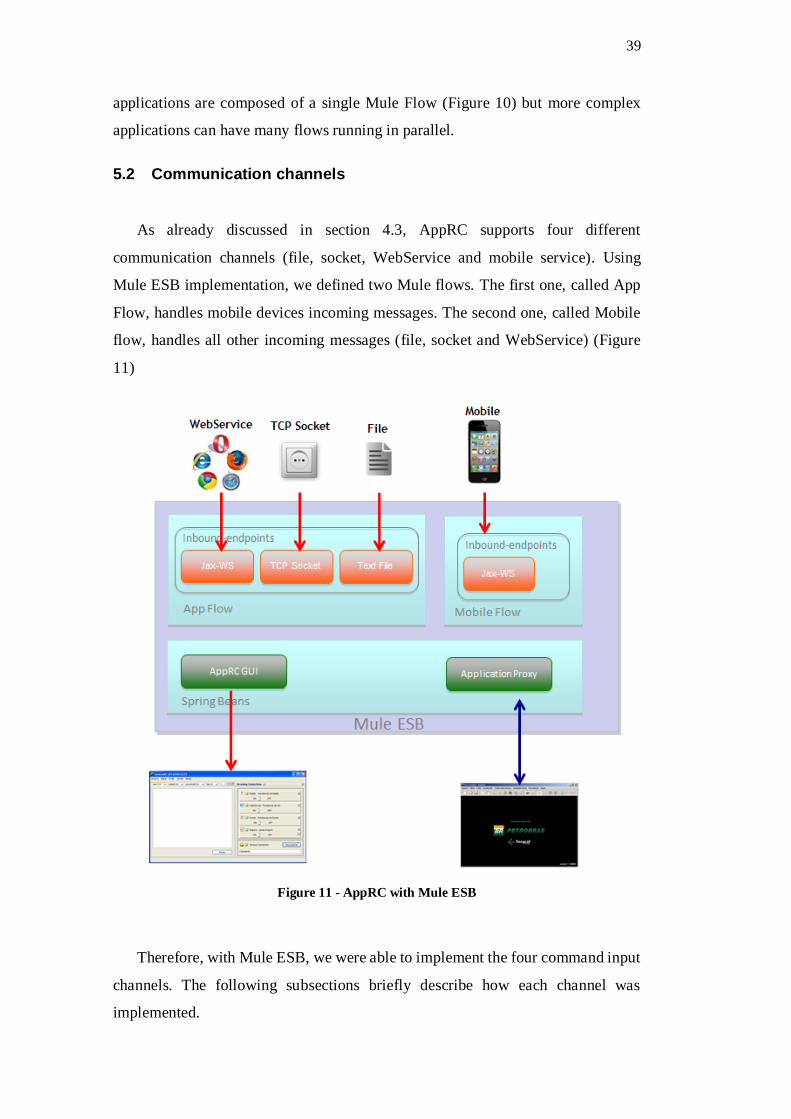
39
applications are composed of a single Mule Flow (Figure 10) but more complex
applications can have many flows running in parallel.
5.2 Communication channels
As already discussed in section 4.3, AppRC supports four different
communication channels (file, socket, WebService and mobile service). Using
Mule ESB implementation, we defined two Mule flows. The first one, called App
Flow, handles mobile devices incoming messages. The second one, called Mobile
flow, handles all other incoming messages (file, socket and WebService) (Figure
11)
Figure 11 - AppRC with Mule ESB
Therefore, with Mule ESB, we were able to implement the four command input
channels. The following subsections briefly describe how each channel was
implemented.

40
5.2.1 File input channel
The simplest way to exchange messages between two applications is via text
files. Therefore, we implemented this kind of interface in our solution, even if it is
not the most efficient way to exchange message, since both applications have to be
running on the same machine or have access to a shared file system. We defined
four basic text files, three of them read-only and one of them write-only, dedicated
to sending commands to the applications. The files are:
input.txt - Write-only, everything written in this file will be consumed
by the AppRC and processed as commands to the application.
output.txt - Read-Only, writes outputs from the application.
processed.txt - Read-Only, keeps track of all processed commands.
log.txt - Read Only, log of the execution, mostly used for debugging.
The user, through the basic GUI, can set the location of the files.
5.2.2 TCP/IP Socket input channel
Sockets are the communication API between processes in a network More
specifically, a socket is a connection point trough which a process can send and
receive information; it is the interface between the application process and the
transport layer protocol. At the sender position, the application sends its message
through a socket. At the other side, the transport layer protocol is responsible to
deliver the message to the right socket destination.
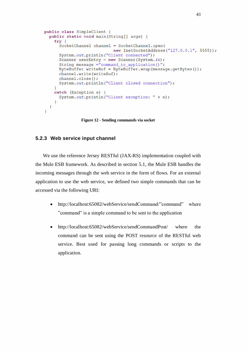
We implemented the socket input as a basic TCP socket where the server
(AppRC) waits the commands as serialized text bytes on a specific port and passes
the message over to the application. Figure 12 shows a simple java code for sending
commands to our framework using socket channel. We opted for adding the socket
communication channel because of the wild spread use of sockets and because of
its simplicity.
41
Figure 12 - Sending commands via socket
5.2.3 Web service input channel
We use the reference Jersey RESTful (JAX-RS) implementation coupled with
the Mule ESB framework. As described in section 5.1, the Mule ESB handles the
incoming messages through the web service in the form of flows. For an external
application to use the web service, we defined two simple commands that can be
accessed via the following URI:
http://localhost:65082/webService/sendCommand/”command” where
”command” is a simple command to be sent to the application
http://localhost:65082/webService/sendCommandPost/ where the
command can be sent using the POST resource of the RESTful web
service. Best used for passing long commands or scripts to the
application.

42
Figure 13 - Web service example with JAX-RS
As we can see in the figure (Figure 13), we used the JAX-RS annotation to
define the web service URI and attributes. The result of a processed command is
written to the output.txt file (as described in Section 5.2.1) and returned to the client
as a JSON object.
5.2.4 Mobile WebService input channel
The mobile channel was implemented the same way as the normal web service
with some adjustments to account for some general mobile connectivity
functionalities and the use of Mobile Application Service extension point
(described in section 5.3). We defined three general commands that are responsible
to manage the connected devices and applications. The commands are:
connect - connects a new mobile device.
disconnect - disconnects a mobile device.
callCommand - calls a command that passes data to the application.
The CallCommand method is used to call one of the defined methods of the
application. In section 5.3.1 we describe in more details how the commands are
organized and sent to the application.

43
AppRC is capable of managing multiple connected devices at the same time,
displaying information in the GUI about each device (type, connection status, name,
etc.). It also resolves the problem of concurrency of commands by arranging the
incoming messages in a queue and delivering them to the applications only when
the application is ready to consume that message.
5.3 Extension Points
In order to keep AppRC generic and extensible, we decided to simplify the work
needed to integrate AppRC to a new application and defined only two extension
points (Figure 14) that need to be addressed by the application developer.
On top of the four input channels, an adapter had to be implemented to handle
the communication between the ESB(AppRC) and the application (Application
Proxy). The problem is that each application may export its functionality in a
different way. Environ, for example, supports LUA commands via a local socket
connection. However, other applications may use direct command line calls, text
file input or any kind of custom method of receiving commands. Moreover, since
these methods may already be implemented in the application, we decided not to
arbitrary force the use of any method as to avoid having to change any code in the
application itself. Instead, we leave the implementation of an Application Proxy
class as an extension point of AppRC, responsible for sending the message received
and processed by AppRC to the application.
Figure 14 - Extension points overview

44
Another extension point we decided to include is the Mobile Application
Service. While developing a mobile application, it is useful to have a middle layer
of abstraction between the responses from the application and the mobile
application. In this layer, from a single mobile command, the developer could, for
instance, request many commands from the application organize the data and then
send it back to the mobile app in a way that is easy to process and display. By adding
this extension point, we are creating a business logic layer without modifying the
original application and keeping the mobile app development simple. If, in the other
hand, the application already has a complete business logic or the mobile app
already implements a complete set of commands, this extension point can be left
out and no additional work is needed to integrate the mobile functionality.
The next sections explain how the extension points were developed. A detailed
explanation of how exactly both extension points were implemented in EnvironRC
can be found in Section 6.2.
5.3.1 Mobile Application Service
The idea behind the creation of this extension point is to provide a custom
interface for the mobile app developer to use, allowing the development of more
complex behaviors and business logic in a single command.
Figure 15 - Mobile application service extension point
As described in the previous section and seen in figure (Figure 15), the mobile
connection input channel has a web service command called “callCommand”. This
web service has, as one of its parameters, the name of the command that should be

45
called. These names are internally mapped to the name of public non-static methods
of a user defined class (MobileApplicationService in Figure 15) that extends the
framework base class called “MobileApplicationServiceBase”. The base class
“MobileApplicationServiceBase” provides the necessary methods to communicate
with the collaboration manager so that the user defined subclass can access and send
messages through the AppRC to the application.
The developer that wishes to use AppRC with a new application needs to define
a simple Java class that extends “MobileApplicationServiceBase”. Every non-static
public method of this new class will represent a command that could be called from
the mobile device. In Figure 16 we can see a basic example of a user defined
extension point class as an example.
Figure 16 - Mobile application service code example
In the example, to call the command “doCustomMobileCommand” the
mobile app should call “MobileConnectionWebService/callCommand” passing the
name of the method as a parameter.
5.3.2 Application Proxy
The application proxy extension point is a required implementation of a base
class that extends AppRC class Proxy. The user defined extension class must fulfill
two goals. First, it needs to be able to send a message to the application and second
it needs to notify the AppRC framework every time there is a message from the
46
application. To achieve both goals some methods have to be implemented by the
class.
sendMessage - Method called by AppRC when there is a message to
send to the application
startApplication - method called by AppRC when a new Instance of the
application is requested in a Session.
close - method called by AppRC when an instance of the application
should be terminated.
In addition, the base class Proxy provides some methods that the subclass
should call when some event happens.
notifyMessageToListners - this method should be called to notify
AppRC of a new message coming from the application
notifyMessageResponseToListeners - this method should be called to
notify AppRC of a message coming from the application as a result from
a previous request
notifyShutdownToListeners - should be called to notify AppRC when
the application instance has been shut down or disconnected.
The exact implementation of the message interface between the Proxy class and
the application is left open to the developer in order to keep the framework generic
and usable by any kind of application. Using Environ, we implement the interface
using a local socket connection, but its usability will heavily depend on the
application.
5.4 GUI
On Figure 17 we present the basic interface. The left side shows the connected
mobile devices, in the middle section we can see the contents of the four basic files
that AppRC writes and reads. It is possible for the user to write commands directly
to input.txt file and send it to the application. The right side shows the status of each

47
input channel and, in a second tab, the status of the connected application instances.
It is also able to run in the background as not to disturb the main visualization.
Figure 17 - Basic AppRC GUI

48
6 EnvironRC Implementation
EnvironRC is our specific use of the AppRC generic solution for the
Environ offshore engineering visualization application. In the following section, we
will describe the aspects of Environ that are relevant for our work. After that, we
discuss the implementation of the Extension Points (Section 6.2). Afterward, in
Section 6.3, we explain the implementation of the mobile application. Finally, we
describe a lightweight application to simplify the sending of commands trough
EnvironRC called EnvironScript (Section 6.4)
6.1 Environ
Environ [1] is a tool designed to allow visualization of massive CAD models
and engineering simulations both in desktop and VR immersive environments. It is
a system composed of a 3D environment for real-time visualization and plug-ins to
import models from other applications, allowing users to view and interact with
different types of 3D data, such as refineries, oil platforms, risers, pipelines and
terrain data (Figure 18). It enables the user to view the simulation in real-time as a
3D environment and enables, at the same time, the user to view all the simulation
data and engineering information.
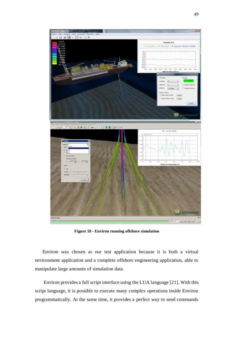
49
Figure 18 - Environ running offshore simulation
Environ was chosen as our test application because it is both a virtual
environment application and a complete offshore engineering application, able to
manipulate large amounts of simulation data.
Environ provides a full script interface using the LUA language [21]. With this
script language, it is possible to execute many complex operations inside Environ
programmatically. At the same time, it provides a perfect way to send commands

50
from an external application to Environ. A sample LUA script for Environ looks
like this:
files = {"P50.128k.a.tdgn", "P50.128k.b.tdgn",
"P50.128k.c.tdgn", "P50.128k.d.tdgn", "P50.128k.e.tdgn" }
for key,value in pairs(files) do
env.load(value)
end
env.setFullscreen(true)
The above script loads many models and sets Environ to run in full screen. To
achieve the integration needed by our framework very few changes were needed on
the application side, since Environ already had a way of receiving messages and
commands through LUA scripts.
6.2 Extension Points
EnvironRC implements both extension points discussed in the previous
sections. In this section, we will discuss the implementation details of both
extension points.
6.2.1 Mobile Environ Service
To help in the development process of the mobile App for Environ, we created
a custom Mobile Application Service to handle high-level commands coming from
the mobile device. The mobile service is also able to do some logic depending on
the command. A good example of the benefits of using this extension point is the
handling of active selection of model objects in Environ. We display in the mobile
device interface a list of selected objects. With many users using the system at once,
(many mobile devices at the same time for instance) it can be a problem to maintain
the current selected objects list updated in all devices. So, we implemented as part
of the Extension Point, a layer of business logic that is in charge of keeping the
selection consistent across all connections. When there is a request from a Mobile
Device to get the selected elements, the custom mobile service will not pass the

51
command direct to the application, instead it process the command internally and
responds accordingly.
Figure 19 - Mobile service extension use
Another way we took advantage of this Extension point was to integrate many
requests into a single web service call. When we open the “settings” page of the
mobile application (further detail in section 6.3), each setting parameter must be
requested to the Environ application as a different LUA command. This would
generate many web services calls and would make the application less responsive
(Figure 19). Therefore, what we did was create a custom command using the Mobile
Service extension point to request all needed settings parameters in one web service
call, heavily reducing the communication delay.
6.2.2 Environ Proxy
The implementation of communication between EnvironRC and Environ was
done using a local socket connection. We had to implement the framework
Extension Point to send the LUA commands to Environ using the socket structure.

52
The implementation of the socket connection was done in a separate thread that
keeps consuming the messages from environ and passing it along to the AppRC
collaboration structure. The thread also consumes a message queue end sends the
new messages to environ.
6.3 EnvironMobile
EnvironMobile is an IOS application developed mainly to help in the
visualization process of complex offshore engineering models in VR environments.
It was developed with the Objective C language as a hybrid application (IPad and
IPhone). It works as an extension of the main application, enabling the user to setup
parameters and view details of the main model being visualized. EnvionMobile
connects to environ using the Mobile connection input channel of EnvironRC.
We defined and implemented seven base functionalities for EnvironMobile:
Configure visualization parameters
Navigate the model structure
Help navigate the virtual world
Create and delete annotations
View and manipulate engineering data
Take snapshots of the scene
Manipulate the collaboration sessions
In the next sections, we will discuss the implementation of each of these
functionalities in further detail.

53
6.3.1 Visualization parameters
Being a complex application as it is, Environ can have many parameters to setup
depending on the kind of visualization the user wants to use. These parameters
range from simple visualization tools like showing the ocean or terrain information,
to complex values tied in to the simulation, like forces applied to risers or sea
current values. As the user will probably need to change the values and inspect
different information during the visualization, it was very important that these
parameters be made available to the mobile device in his or her hands. Therefore,
our first priority was to implement a complete set of commands for visualization
parameters and the interface to manage them. (Figure 20 shows a sample of the
Mobile interface). We followed the standard settings interface of the IOS platform.
Figure 20 - Environ mobile visualization settings
The visualization parameters of Environ include settings of the 3D scene, like
skybox, ocean and terrain settings. We can also set the camera and light settings of
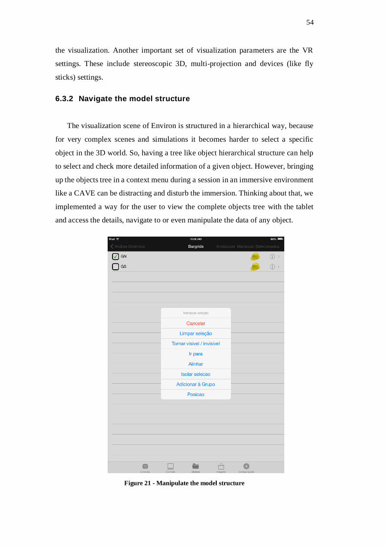
54
the visualization. Another important set of visualization parameters are the VR
settings. These include stereoscopic 3D, multi-projection and devices (like fly
sticks) settings.
6.3.2 Navigate the model structure
The visualization scene of Environ is structured in a hierarchical way, because
for very complex scenes and simulations it becomes harder to select a specific
object in the 3D world. So, having a tree like object hierarchical structure can help
to select and check more detailed information of a given object. However, bringing
up the objects tree in a context menu during a session in an immersive environment
like a CAVE can be distracting and disturb the immersion. Thinking about that, we
implemented a way for the user to view the complete objects tree with the tablet
and access the details, navigate to or even manipulate the data of any object.
Figure 21 - Manipulate the model structure
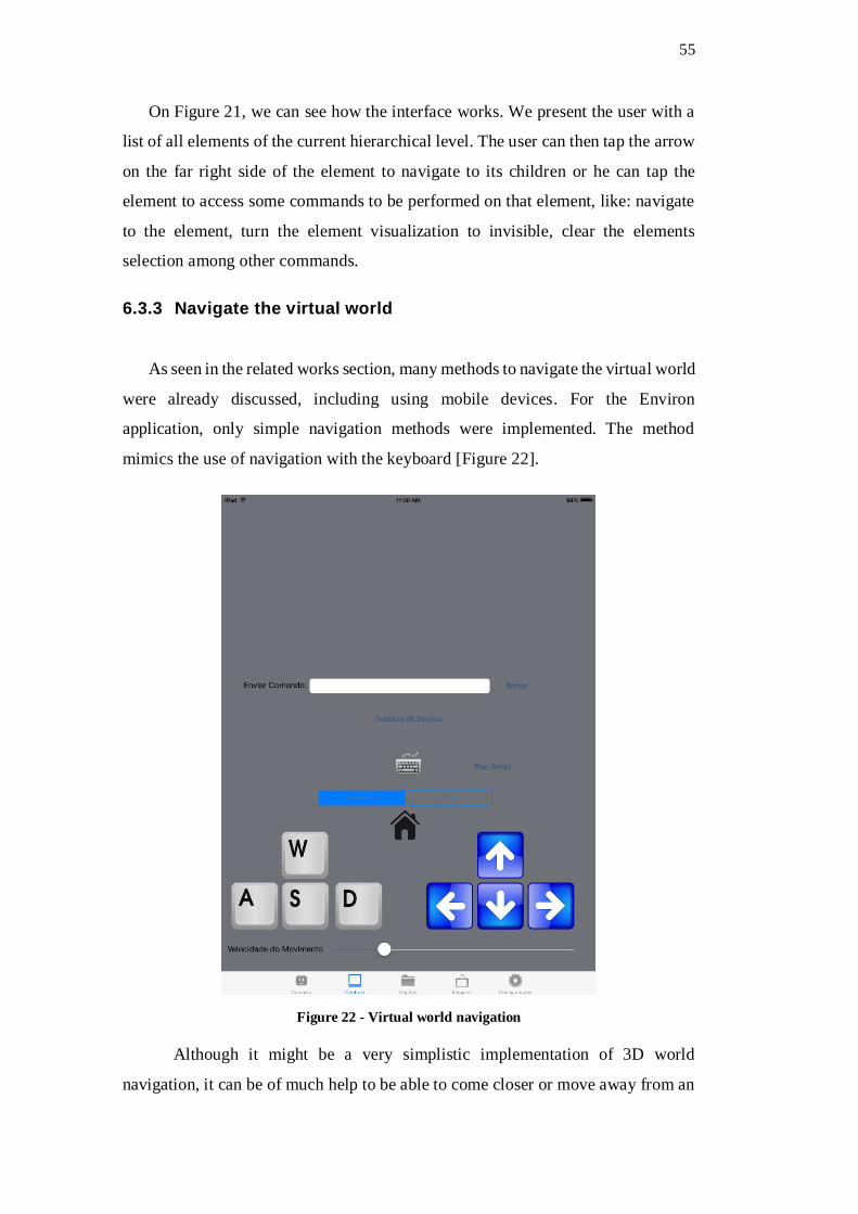
55
On Figure 21, we can see how the interface works. We present the user with a
list of all elements of the current hierarchical level. The user can then tap the arrow
on the far right side of the element to navigate to its children or he can tap the
element to access some commands to be performed on that element, like: navigate
to the element, turn the element visualization to invisible, clear the elements
selection among other commands.
6.3.3 Navigate the virtual world
As seen in the related works section, many methods to navigate the virtual world
were already discussed, including using mobile devices. For the Environ
application, only simple navigation methods were implemented. The method
mimics the use of navigation with the keyboard [Figure 22].
Figure 22 - Virtual world navigation
Although it might be a very simplistic implementation of 3D world
navigation, it can be of much help to be able to come closer or move away from an

56
object using the mobile device. Environ has two types of 3D world navigation
paradigms; “Examine” and “Fly”. Using the Examine mode, the user camera has a
set point of view center point, and he moves around this center point. It is very
useful when analyzing a specific point in the model. The other mode is Fly, in which
the controls work as if the user was flying through the scene.
Our communication and collaboration solution supports any kind of
navigation, including more complex implementations using the internal sensors of
the mobile device like accelerometers and gyroscopes. However, it fell out of the
scope of our work and in our experience with EnvironRC in VR Setups, the use of
the simple provided controls in conjunction with the ability to select any structure
from the model and directly navigate to it, although not optimal, proved very
effective in helping the visualization.
6.3.4 Manipulate annotations
Virtual 3D annotations are a very useful feature of Environ. They help the
user understand details of the virtual model since each annotation is always coupled
to a specific part of the model being visualized. All annotations can be seen in the
mobile device as list (Figure 23). This is especially useful when the user needs to
setup a list of tasks to be done in a remote location. For example, a user using the
desktop application can create a sequence of annotations, each representing a task
that needs to be done on s specific part of the model. A second user in a remote
location (an oil platform for example) connected to the same session, can see the
annotations and its locations and perform the tasks. He can even create new
annotations or edit the ones already present.

57
Figure 23 - List of annotations
6.3.5 Manipulate engineering data
As mentioned before, when inside the VR environment, any kind of menu or
big text block viewed in the application disturbs the immersion. A mobile device
offers a second screen where we could display many kinds of data like: large tables
of numbers, graphs, detailed information, etc.
We implemented a way for the user to request engineering data detail of any
object of the scene (Figure 24). This feature proved the most useful when using the
mobile device in VR setups, as it helps the review process of an offshore simulation
when the user can see multiple data tables of the specific simulation timestamp
being presented in the main visualization screen.
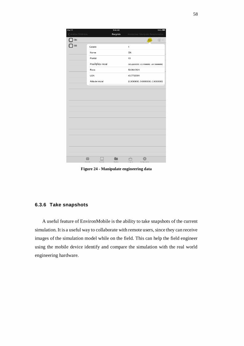
58
Figure 24 - Manipulate engineering data
6.3.6 Take snapshots
A useful feature of EnvironMobile is the ability to take snapshots of the current
simulation. It is a useful way to collaborate with remote users, since they can receive
images of the simulation model while on the field. This can help the field engineer
using the mobile device identify and compare the simulation with the real world
engineering hardware.

59
Figure 25- Mobile snapshot
A more complete implementation of this feature would include the ability to
stream as video the content of the visualization directly to the mobile device in real-
time. However, to implement this complete feature would require a lot of extra work
and was left outside the scope of the current work.
6.3.7 Manipulate the collaboration session
In order to manage the collaboration aspect of EnvironRC, we implemented
a special screen to manipulate the collaboration session. Here the user can see the
available applications to send commands to, the number of other users in the
session, create new instances of the application, start broadcasting a message or
remove an application session from the session.

60
Figure 26 - Collaboration control
This is the only functionality that does not concerns environ directly. It
invokes only methods of EnvironRC that do not connect directly to Environ. It
manipulates the collaboration session using only control messages (as described in
section 4.4).
6.4 EnvironScript
EnvironScript is a Java application that was developed to help an external
application send commands to Environ. The motivation to create this simple
application was to enable a PowerPoint presentation to control an Environ
application running on another computer.
In order to communicate with EnvironRC, the application has to use one of
our four input channels (file, socket, web service and mobile web service).
PowerPoint is an application over which we do not have any control or any easy

61
way to access sockets, write files or send web service requests. Therefore, we
created the EnvironScript application. It is a command line application that receives
the LUA scripts it needs to send to environ along with a configuration file in XML
format.
EnvironScript is essentially an easier way to send simple scripts to Environ.
It has, however, some important limitations. It only sends the scripts to be executed
by the target applications in the sessions, it cannot process responses. It can also
only use the web service and socket input channels.
Figure 27 - EnvironScript configuration XML
An example of a XML configuration file can be seen in Figure 27.There are
two main parameters that need to be setup in the configuration XML. First is the
folder in which EnvironScript will look for the scripts to send. Second is the address
where the AppRC Server is running on, that is, its IP address and port.
62
7 Results
In this chapter, we will discuss two main results of EnvironRC. First, in section
7.1, we describe the experiment that was conducted with users to determine the
benefits of having a mobile device while using a VR setup. Second, in section 7.2,
we present a real-world case of EnvironRC being used in NVC (Collaborative
Visualization Center) in CENPES/Petrobras.
7.1 Experiment
The goal of our experiment was to analyze and determine the benefits (if any)
for the user experience of running Environ in a VR session with and without our
solution. For the experiment, the users had to perform a series of tasks during a VR
session in two different conditions: first without our solution and then using the
mobile device connect to the Environ application through EnvironRC. To complete
the tasks without EnvironRC, the participants were asked to use standard mouse
and keyboard inputs. This decision was made because although there are many
different devices to help navigate the 3D world (as discussed in Chapter 2), none of
them can help the user manipulate engineering data or use 2D menus to configure
the application. On top of that, most CAVEs setup today use keyboard and mouse
to perform these tasks.
The experiment is described in the following sections in three stages: first we
describe the steps needed to setup the experiment, then we discuss the experiment
execution and finally we analyze the results.
7.1.1 Experiment preparation
The preparations steps needed to setup the experiment were:
Definition of test environment.
Definition of experiment tasks.
Definition of participant profile.
Preparation of materials and documents for the experiment.

63
Pilot test of the experiment.
The above steps are described in the following sections.
7.1.1.1 Experiment environment
To test our solution, we used a visualization system of type CAVE. A CAVE
has the problems we wanted to address with this dissertation. Some of these
problems include:
Users have to be standing
User has to use 3D glasses
Multiple projection screens, making menu navigation hard
Large projection screens, making texts harder to read
We used the CAVE VR system of Tecgraf/PUC-RIO. This specific CAVE has
four projectors with optical head-tracking, giving the user a high degree of
immersion.
The specific hardware configuration of the CAVE used was:
Main PC running the CAVE: CPU Intel Core i7 965 @ 3,20 Ghz; RAM
12GB; Windows 7 x64 OS
1x NVIDIA Quado Plex 2200 workstation
Four big projection screens
Four head-tracking sensors
Tablet Ipad 2 running EnvironMobile
7.1.1.2 Experiment tasks
As mentioned before, one of the main problems engineering applications face
when running in VR setups is the difficulty to represent any kind of 2D menu
navigation. This happens specially when trying to read large amounts of data (as

64
numbers or tables) or when trying to navigate 2D menus to change any visualization
parameters.
To study the impact of our solution when trying to solve these problems, we
defined two different tasks for the participants to perform. One of them to study the
impact when reading large amounts of data and the second one was designed to
study the impact of changing visualization parameters. Another important
distinction between the two tasks is the fact that the first task requires the participant
only to read the values he/she sees in the virtual world, while the second task
requires the user to input numerical values as parameters. Both tasks are described
in the following sections.
Task 1 – Reading engineering data
The goal of task 1 is to test the impact of having a mobile device when trying
to read engineering data values from a specific object. The participant starts with a
full visualization of the offshore engineering model. The participant is asked to use
the object navigation interface of Environ to select a specific object in the scene.
Once selected, he/she should invoke the “go to” command to go to the selected
object and visualize it. After that, the participant is instructed to read out loud the
values of three engineering parameters of the selected object.
Task 2 – Changing visualization parameters
Changing visualization parameters is a very common task when using VR
setups. Visualization parameters include: graphic quality parameters, immersive
system parameters, stereoscopic 3D parameters and others. The goal of this task is
to change three visualization parameters:
1. Change the skybox from “color: black” to “sky: twilight”.
2. Change the stereoscopic eye distance from 0,0175 to 0,02.
3. Change the distance to parallax zero from 1,0 to 0,9.

65
7.1.1.3 Participants’ profile
We recruited fourteen participants, with ages between 26 and 45. All of them
had experience with VR setups. Only 2 of the participants had not used any kind of
engineering applications in VR, but had experience with 3D software like
modelling tools and games. All participants had at least a graduation degree in the
field of computer science and 78% had a postgraduate degree in the field. There
were thirteen males and one female participant.
7.1.1.4 Experiment material and documents
The documents used for the experiment (shown in Appendix A) were:
Short Environ manual. (Appendix A.1)
Task 1 and 2 Description. (Appendix A.2)
Consent form (Appendix A.3)
Pre-use question form (Appendix A.4)
Post-use question form (Appendix A.5)
Post-use interview script (Appendix A.6)
All documents for the experiment were written in Portuguese because the
experiment was conducted in Rio de Janeiro, Brazil.
7.1.1.5 Pilot test
A pilot test of the experiment was conducted to validate the experiment
material, documents and process. The goal of the pilot test was to identify any
problems that were not accounted for. The results of the test run were not considered
as part of our analyses.
Based on the results of the pilot test, we decided to make a single adjustment to
the experiment; We decided to add a flat surface near the CAVE setup with a mouse
and keyboard. Before the pilot test, we had decided that the participants would try
to use the mouse and keyboard while standing, but in most VR setups there is often
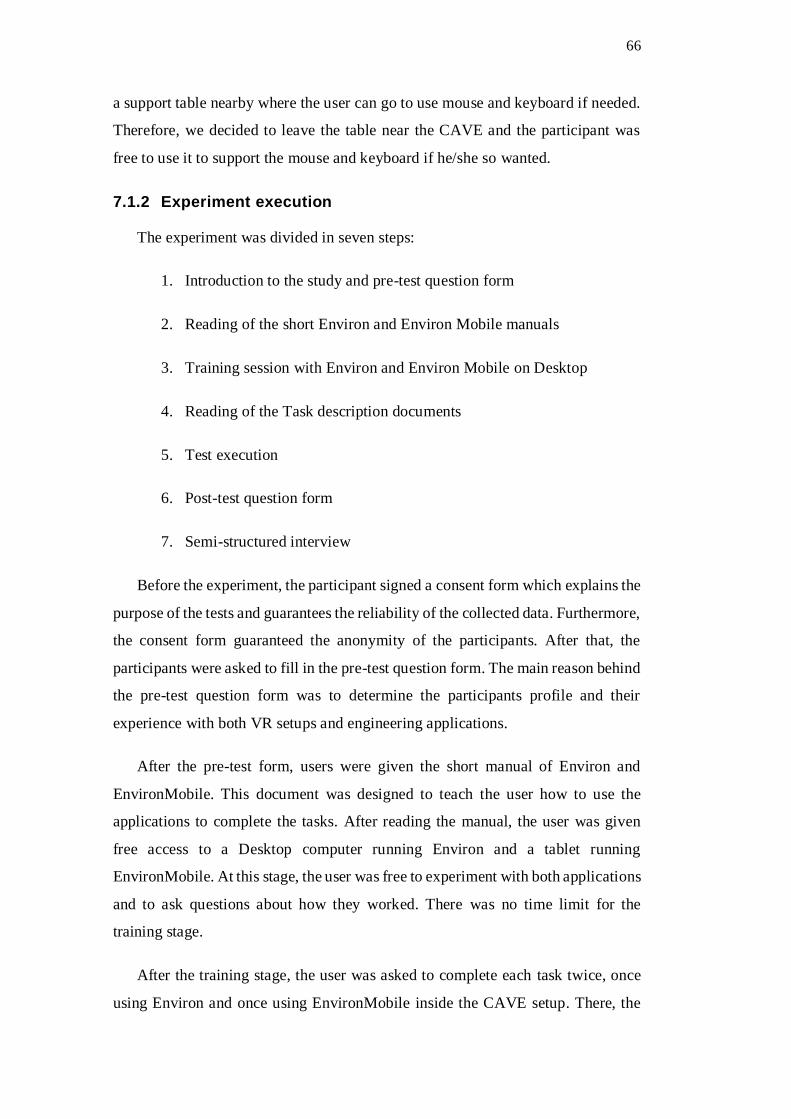
66
a support table nearby where the user can go to use mouse and keyboard if needed.
Therefore, we decided to leave the table near the CAVE and the participant was
free to use it to support the mouse and keyboard if he/she so wanted.
7.1.2 Experiment execution
The experiment was divided in seven steps:
1. Introduction to the study and pre-test question form
2. Reading of the short Environ and Environ Mobile manuals
3. Training session with Environ and Environ Mobile on Desktop
4. Reading of the Task description documents
5. Test execution
6. Post-test question form
7. Semi-structured interview
Before the experiment, the participant signed a consent form which explains the
purpose of the tests and guarantees the reliability of the collected data. Furthermore,
the consent form guaranteed the anonymity of the participants. After that, the
participants were asked to fill in the pre-test question form. The main reason behind
the pre-test question form was to determine the participants profile and their
experience with both VR setups and engineering applications.
After the pre-test form, users were given the short manual of Environ and
EnvironMobile. This document was designed to teach the user how to use the
applications to complete the tasks. After reading the manual, the user was given
free access to a Desktop computer running Environ and a tablet running
EnvironMobile. At this stage, the user was free to experiment with both applications
and to ask questions about how they worked. There was no time limit for the
training stage.
After the training stage, the user was asked to complete each task twice, once
using Environ and once using EnvironMobile inside the CAVE setup. There, the

67
user had to wear stereoscopic 3D glasses and stand up inside the cave. He/she was
first asked to complete both tasks without EnvironMobile. To do so, the participant
could use mouse and keyboard. After that, he/she was asked to complete the same
tasks using EnvironMobile. A measurement of time spent in each task with each
device was taken.
Finally, after the execution of the tests, the participant was asked to fill in the
post-test question form. This form was used as a tool to determine the user
experience in the CAVE. Some aspects we wanted to study with the post-test form
were: usability, how (or if) both solutions disturbed the immersion, impact of 3D
glasses while using a tablet and others. The question form consists of eleven
statements. We used a Likert scale for each statement where 1 represents full
disagreement and 5 represented complete agreement. The full post-test question
form can be found in Appendix A.5 and in Figure 29.
At the end, a semi-structured interview was conducted in order to determine
how the participant felt about both ways of completing the tasks. Furthermore, we
used the semi-structured interview to clarify the answers given by the participant in
the post-test form and ask for improvement suggestions.
7.1.3 Results analysis
In this section, we will present the main observations done while running the
experiment, as well as difficulties and suggestions the participant had.
First we will analyze the time needed by each participant to complete each task.
The results can be seen in Figure 28.
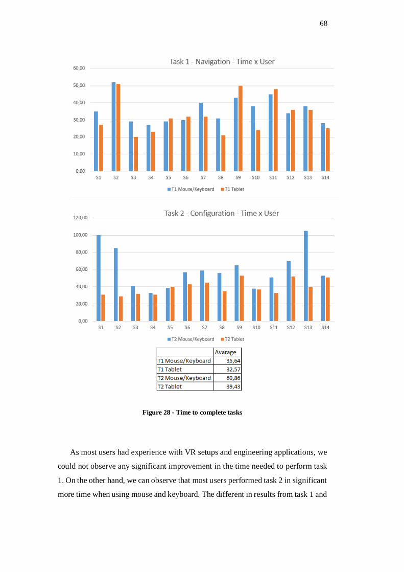
68
Figure 28 - Time to complete tasks
As most users had experience with VR setups and engineering applications, we
could not observe any significant improvement in the time needed to perform task
1. On the other hand, we can observe that most users performed task 2 in significant
more time when using mouse and keyboard. The different in results from task 1 and

69
task 2 is most likely explained duo to the fact that task 2 required the user to input
numerical values using the keyboard.
To further analyze and understand the results of the experiment, we show the
result of the post-test question form in Figure 29.
Figure 29 - Post-test results
From Figure 29, we can see that the users thought the task was easier to
complete using EnvironMobile in comparison with standard input devices. (Q1 –
Q4). During the semi-structured interview, most users reported that using mouse
and keyboard in a CAVE was very unpractical and because of that, using a CAVE
setup alone was very hard, often requiring a second person to help navigate the
menus. These users thought that having a tablet made it practical to complete the
tasks in the CAVE alone.
A very common complaint during the interviews was that the size of the text on
the projection screen was very hard to read. There are two main reasons for that.
First, the projection screen is very large and has a high resolution making the text

70
very small. Second, most stereoscopic 3D glasses work using some kind of color
filtering mechanism that makes the image darker, and therefore harder to read. To
further analyze the impact of 3D glasses, we can see that most users thought the 3D
glasses had a small impact when using the tablet screen (Q9). One user did complain
that the colors on the tablet screen were not very clear using the 3D glasses, but he
mentioned it was of low impact for his experience.
Some users mentioned that the EnvironMobile interface could be improved.
One user suggested that the EnvironMobile interface should try to mirror the main
Environ application perfectly. Furthermore, when asked about the impact the tablet
had on the immersion, almost all users said that having to look away from the main
projection screens to the 2D interface of the tablet did lower the immersion, but was
of a much lesser impact than having to use mouse and keyboard. The results of Q6
further accentuate this difference, with most users agreeing that the tablet did have
a positive impact on the immersion experience.
From the interviews, it became clear that although some users could complete
the task in similar times with or without our solution, the use of keyboard and mouse
did never offer a good immersion experience.
7.2 EnvironRC in NVC
The presented architecture and solutions are current in use in NVC
(Collaborative Visualization Center) in CENPES/Petrobras. In this section, we will
discuss a special use of EnvironRC during the review process of a very large
offshore engineering project involving a BSR system (Riser sustaining buoy)
(Figure 30).

71
Figure 30 - BSR illustration model
7.2.1 BSR Project
The project we analyzed involves deep see oil exploration. The total sea depth
at the oil field where the project was implemented is of 2140m. The project consists
of a BSR that stays stationary around 250m below sea level. The buoy structure is
anchored to the sea floor by eight rigid anchor lines. The main goal of the buoy is
to alleviate the stress on the risers induced by the movement of the platform.
Without the BSR all the risers would go from see floor all the way to the platform,
and they should be resistant enough to support all the forces coming from the
movement of the platform. The platform suffers movement duo to the external
forces applied to it (current, wave, winds etc…).
The BSR works as a way to separate the movement of the platform from the
long risers’ lines. There are two set of risers, first the flexible (and more expensive)
risers going from the platform to the BSR (at 250m below sea level) (Figure 31).
The second set of risers goes from the BSR to the sea floor (at 2140m below sea
level) and since the movement from the platform does not affect the second set of

72
risers, they can be of a rigid and more cost effective type. The BSR works as a sort
of damper, absorbing the movement of the platform and not transmitting it to the
rigid risers. The way it achieves this is by having the ability to pivot on the side of
the risers that goes to the platforms.
Figure 31 - Two BSR overview
The complete BSR Project took many years of study and involved many
areas of the offshore engineer field, making it a very good example for our solution.
There was a huge amount of simulations done for every step of the project. These
simulations where divided in two main phases: installation phase and operational
phase. There were more than a thousand simulation cases for each of the phases,
involving every kind of failure or condition.
7.2.2 Review process in NVC
The simulations are a very complex numerical computational problem and have
to run offline. Each simulation is then stored in a GXML file and these files can be
opened and visualized by Environ in the Virtual reality setups in NVC.
The visualization capabilities of the VR setups in NVC help offshore engineers
during the review process and these visualizations of big offshore engineering

73
projects were the main motivation of this work. Our solution is used in NVC
regularly to help the review and visualization of the results. One special case we
would like to study in more details, is the review process of the BSR project that
took place in the main visualization room of NVC and involved a large amount of
simulations and a large amount of engineers.
Because of the number of people present on the day of the review, all the
models were to be presented using the PowerWall setup. The PowerWall
presentation room in NVC has the main visualization screen and a supporting
screen for presentation (Figure 32). All offshore engineers were to present their
results and show the simulated models that had interesting details and facts that
could indicate some problems for the overall project.
The presenter (mostly offshore engineers) had a PowerPoint presentation
that would run on the second screen and the simulation results would be presented
on the main PowerWall screen. The presenter could send commands and control
the simulation via the PowerPoint presentation as well as with an IPad running
EnvironMobile. A complete schematic of how our solution was used to achieve this
kind of integration and collaboration can be seen in Figure 33.
Figure 32 - Powerwall setup in NVC
74
Figure 33 - EnvironRC on BSR Review process
For the review process of the BSR project, seven simulation results were
chosen to be presented. Since each simulation takes a very long time to load using
the visualization setup, we chose to have all seven simulations loaded using
different instances of Environ and have EnvironRC manage them. In total, there
were eight instances of Environ connected to the EnvironRC session, seven for each
model and one with a general overview model used only to explain the idea behind
BSR.
The presentation PC had all the PowerPoints the presenters were going to
use. Each PowerPoint was previously setup to be able to invoke EnvironScript to
send a command to Environ. As an example, we can see in Figure 34 that the
presenter could at any time click in the link in the presentation itself to send the
command to bring his simulation to the foreground and start/pause/stop the
simulation.

75
Figure 34 - PowerPoint Slide using EnvironScript
In Figure 35 we show an example script used in the presentation. The scripts
begin by sending a control message (“--@BROADCAST_BEGIN”) telling
EnvironRC that the next messages should be sent to all connected instances. Next
comes the LUA commands responsible for minimizing the application instance.
Then the script tells EnvironRC to stop broadcast with another control message (“-
-@BROADCAST_END”) and selects which Environ instance should be targeted
next (“--@USE_APP(Environ_0)”) and finally sends the commands to do some
visualization setup for the targeted model, in this case, make a model visible and
show the plot of a graph.
Figure 35 - Example BSR Environ script
On top of the integration with the PowerPoint PC, we had a mobile device
assisting the entire process, as seen in Figure 36. With the mobile device, the
presenter could, in real time, change the visualization and navigate to a different

76
spot in the scene. He could also check engineering data of the model to better
answer the questions of the viewers. Using the already discussed functionalities of
EnvironMobile, the presenter was able to control and communicate with all eight
instances of the application at the same time.
Figure 36 - Mobile on BSR review
The PC running on the main visualization screen was a custom build state of
the art machine running a 32 core CPU with two dedicated external NVDIA Quadro
Plex graphic cards. The presentation PC was a standard laptop since it was used
only to run PowerPoint and the mobile device used was an IPad 2. All devices were
connected to the same network via WiFi and we achieved real time manipulation
and collaboration.
The review process of BSR was a real world, heavy load test case for our
solution and we were able to handle all the communication in a real time scenario
and still add all the benefits of having a collaborating system in an offshore
engineering project review in a VR environment.
7.2.3 Performance
The average response time of a request from the mobile device to the main
visualization application was of 0.67 seconds. Jakob [27] defined three main time

77
limits for applications responses. Our result stay inside the second limit category
where the users has the impression that the computer is working on the request but
can still freely navigate the interface.
We performed tests of Environ running with and without EnvironRC connected,
but could not find any significant performance difference. This probably happens
because of the nature of Environ (and engineering applications), the load of the
visualization and simulation part of Environ is much greater than the load of the
communications between applications, making the performance difference
negligible.

78
8 Conclusion
Our goal with this work was to study the use of EnvironRC to help offshore
engineering applications run in VR environments. On top of that we wanted to
enable collaboration unaware application to collaborate and exchange messages.
As the result of this work, we could demonstrate that EnvironRC brought real
benefits to offshore visualization applications running in VR setups. The main
benefits were that having a connected tablet device when inside a CAVE setup
enabled the users to manipulate engineering data and configure the visualization
parameters. Furthermore, we showed that using a tablet had a lesser negative impact
to the immersion experience then traditional input devices.
EnvironRC is in use by PETROBRAS at CENPES as a way to enhance the
experience of Environ in many different kinds of virtual reality setups like a CAVE
and an L-shape display. EnvironRC is also in use with an Ultra-HD display (20x
HD) that, because of the very high resolution, enables the use of multiple instances
of Environ on the same display with many users at the same time. Furthermore, it
enables the user of Environ to navigate the 3D world, review engineering data,
create 3D annotations or even take snapshot pictures of the simulations from a
mobile device.
Furthermore, AppRC was designed to be lightweight, extensible, as well as
flexible enough to accommodate the different kinds of needs of any kind of
application. AppRC requires little development work in order to achieve the
integration. By implementing only two basic classes, and with minimum change to
the base application, it is possible for any application to export its functionalities,
not only to a mobile device, but also to any other application using one of the four
available input channels. AppRC meets all of the requirements we listed in chapter
4 and offers easy way to integrate collaboration layer to any application.
We had success running EnvironRC in a collaborative setup (as described in
section 7.2.2), but further studies are still needed. When adding collaboration
capabilities to an application, we add a large amount of new ways to interact with
the application and other users. A possible future work is to conduct a more
79
complete study with different collaboration sessions and how much each session
type benefits the users.
Although most immersive VR setups share the same kinds of problems with a
CAVE setup, further studies running the same experiment in different VR setups
could help to validate our results.
One problem we would like to address in the future is to also streamline the
mobile application development process. As it is right now, to integrate mobile
functionalities to a new application, the user needs to develop the mobile
application from scratch. Moreover, if the user wants the mobile App on different
platforms (IOS and Android, for example), the work would be doubled. We are
beginning to study ways to define a protocol to try to extract the commands from
an application and programmatically build a mobile application interface based on
HTML5 for the application that will work with any mobile platform.
Further studies not included this work involve the use of our solution to
integrate applications outside the field of offshore engineering. One possible focus
of a further study is Geophysical analysis application. The review process of
geophysical simulations requires the real-time comparison of different models. This
kind of review process fits very well with the benefits that our solution adds,
allowing the user to control many instances of the application simultaneously.
The benefits of having collaborating applications in VR Setups could be studied
other kinds of applications outside the scope of engineering. One field that could
possibly be of interest is medical applications. There are already many 3D
visualization applications in the field of medicine that could use our solution to run
different visualizations to compare data.
80
9 Bibliography
1. RAPOSO, A., SANTOS, I., SOARES, L., WAGNER, G., CORSEUIL, E.,
GATTASS, M. Environ: Integrating VR and CAD in Engineering Projects.
IEEE Computer Graphics & Applications, v.29, n.6, p.91-95, 2009.
2. DOS SANTOS, Ismael HF; RAPOSO, Alberto B.; GATTASS, Marcelo. A
software architecture for an engineering collaborative problem solving
environment. In: 32nd Annual IEEE Software Engineering Workshop.
IEEE, 2008. p. 43-51
3. W. Reinhard et al., “CSCW Tools: Concepts and Architectures”, IEEE
Computer, 27(5): 28-36, 1994.
4. SANTOS, I. H. F., RAPOSO, A. B., GATTASS, M. Finding Solutions for
Effective Collaboration in a Heterogeneous Industrial Scenario. 7th
International Conference on Computer Supported Cooperative Work in Design
- CSCWD 2002, p.74 - 79. Rio de Janeiro, Brazil. 2002
5. PEDRAS, Bernardo FV; RAPOSO, Alberto; SANTOS, Ismael HF. AppRC: A
framework for integrating mobile communication to virtual reality applications.
In: Proceedings of the 12th ACM SIGGRAPH International Conference on
Virtual-Reality Continuum and Its Applications in Industry. ACM, 2013. p.
305-308.
6. C. Cruz-Neira, D. J. Sandin, T. A. DeFanti, R. V. Kenyon, and J. C. Hart, “The
cave: audio visual experience automatic virtual environment,” Commun. ACM,
vol. 35,no. 6, pp. 64–72, Jun. 1992. [Online]. Available:
http://doi.acm.org/10.1145/129888.129892
7. MEDEIROS, D., CARVALHO, F., RAPOSO, A., AND SANTOS, I. H. 2013.
An interaction tool for immersive environments using mobile devices. 90–96.
8. NORONHA, H., CAMPOS, P., JORGE, J., ARAÚJO, B., SOARES, L., AND
RAPOSO, A. 2012. Designing a mobile collaborative system for navigating and
reviewing oil industry cad models.

81
9. KATZAKIS, N., HORI, M., AND . 2011. Smartphone game controller (). ŁŁ
35, 25, 55–60.
10. DE PAIVA GUIMARAES, M., GNECCO, B. B., AND ZUFFO, M. K. 2004.
Graphical interaction devices for distributed virtual reality systems. In
Proceedings of the 2004 ACM SIGGRAPH international conference on Virtual
Reality continuum and its applications in industry, ACM, New York, NY, USA,
VRCAI ’04, 363–367.
11. TAYLOR, R. M., II, II, R. M. T., HUDSON, T. C., SEEGER, A., WEBER, H.,
JULIANO, J., AND HELSER, A. T., 2001. Vrpn: A device-independent,
network-transparent vr peripheral system.
12. TEIXEIRA, L., TRINDADE, D., LOAIZA, M., CARVALHO, F. G. D.,
RAPOSO, A., AND SANTOS, I. 2012. A vr framework for desktop
applications. In Proceedings of the 2012 14th Symposium on Virtual and
Augmented Reality, IEEE Computer Society, Washington, DC, USA, SVR ’12,
10–17
13. FLICK SOFTWARE, 2015. http://flicksoftware.com/flick-technologies/flick-
development-libraries/.
14. MAXIMO, 2015. http://www-
03.ibm.com/software/products/us/en/maximoassetmanagement/
15. EZMAXMOBILE, 2015. http://ezmaxmobile.interprosoft.com/.
16. IMAXEAM, 2015. http://imaxeam.com/maxinterface-integration-tool.
17. SANTOS, Ismael HF et al. Integrating The Galileo Applications For Simulation
of Offshore Systems Via The GXML Unified Format. In: XXX CILAMCE-
Iberian Latin American Congress on Computational Methods in
Engineering. 2009. p. 1-15.
18. FUKS, Hugo et al. Applying the 3C model to groupware development.
International Journal of Cooperative Information Systems, v. 14, n. 02n03,
p. 299-328, 2005.
82
19. BRIGGS, Robert et al. Defining key concepts for collaboration engineering.
AMCIS 2006 Proceedings, p. 17, 2006.
20. W.E. Mackay. “Media Spaces: environments for informal multimedia
interaction”. In Computer Supported Cooperative Work, M. Beaudouin-Lafon,
Ed., vol. 7 of Trends in Software. John Wiley & Sons, 55-82, 1999.
21. IERUSALIMSCHY, R. 2006. Programming in Lua, Second Edition.Lua.Org.
22. MASSOL, Vincent; O'BRIEN, Timothy M. Maven: A Developer's Notebook:
A Developer's Notebook. " O'Reilly Media, Inc.", 2005.
23. MULE ESB FRAMEWORK, 2015.
http://www.mulesoft.org/documentation/display/current/Home.
24. APACHE CAMEL ENTERPRISE APPLICATION INTEGRATION, 2015.
http://camel.apache.org/.
25. SPRING INTEGRATION, 2015. http://www.springsource.org/spring-
integration.
26. BURKE, Bill. RESTful Java with JaX-RS. " O'Reilly Media, Inc.", 2009.
27. NIELSEN, Jakob. Usability engineering. Elsevier, 1994.
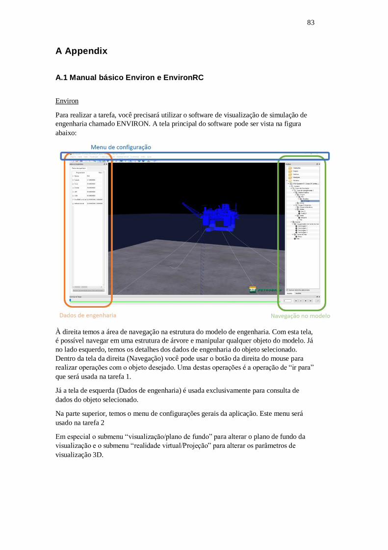
83
A Appendix
A.1 Manual básico Environ e EnvironRC
Environ
Para realizar a tarefa, você precisará utilizar o software de visualização de simulação de
engenharia chamado ENVIRON. A tela principal do software pode ser vista na figura
abaixo:
À direita temos a área de navegação na estrutura do modelo de engenharia. Com esta tela,
é possível navegar em uma estrutura de árvore e manipular qualquer objeto do modelo. Já
no lado esquerdo, temos os detalhes dos dados de engenharia do objeto selecionado.
Dentro da tela da direita (Navegação) você pode usar o botão da direita do mouse para
realizar operações com o objeto desejado. Uma destas operações é a operação de “ir para”
que será usada na tarefa 1.
Já a tela de esquerda (Dados de engenharia) é usada exclusivamente para consulta de
dados do objeto selecionado.
Na parte superior, temos o menu de configurações gerais da aplicação. Este menu será
usado na tarefa 2
Em especial o submenu “visualização/plano de fundo” para alterar o plano de fundo da
visualização e o submenu “realidade virtual/Projeção” para alterar os parâmetros de
visualização 3D.
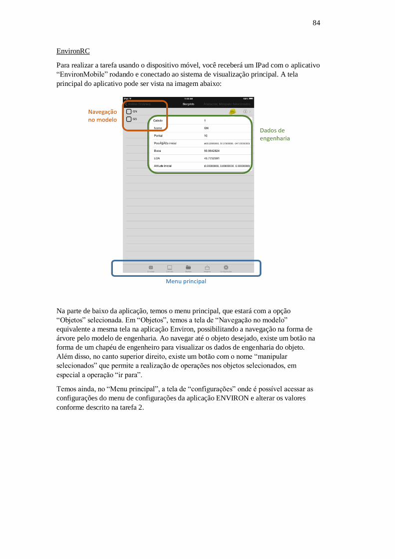
84
EnvironRC
Para realizar a tarefa usando o dispositivo móvel, você receberá um IPad com o aplicativo
“EnvironMobile” rodando e conectado ao sistema de visualização principal. A tela
principal do aplicativo pode ser vista na imagem abaixo:
Na parte de baixo da aplicação, temos o menu principal, que estará com a opção
“Objetos” selecionada. Em “Objetos”, temos a tela de “Navegação no modelo”
equivalente a mesma tela na aplicação Environ, possibilitando a navegação na forma de
árvore pelo modelo de engenharia. Ao navegar até o objeto desejado, existe um botão na
forma de um chapéu de engenheiro para visualizar os dados de engenharia do objeto.
Além disso, no canto superior direito, existe um botão com o nome “manipular
selecionados” que permite a realização de operações nos objetos selecionados, em
especial a operação “ir para”.
Temos ainda, no “Menu principal”, a tela de “configurações” onde é possível acessar as
configurações do menu de configurações da aplicação ENVIRON e alterar os valores
conforme descrito na tarefa 2.

85
A.2 Descrição das Tarefas 1 e 2
Tarefa 1: navegar e visualizar um objeto na cena usando o comando “ir para” e consultar
dados de engenharia
Nesta tarefa você inicia com o modelo carregado e com uma visão geral de todo o arranjo
submarino. O Objetivo é navegar com a câmera até um determinado objeto na cena que
está localizado no fundo do oceano.
Para completar esta tarefa, você deve navegar na estrutura do modelo até o objeto
“Ancoragem 3” e usar o comando “Ir para”.
O Objeto “Ancoragem 3” se encontra no seguinte caminho dentro do modelo GXML:
“Cenário/layout/Equipamentos de fundo do mar/Ancoragem 3”. Com o Objeto
selecionado e sendo visualizado, você deve consultar o valor das propriedades “Largura”,
“Altura” e “Profundidade” do modelo, lendo seus valores em voz alta.
Tarefa 2: Alterar parâmetros da visualização
Nesta tarefa você inicia com o modelo carregado e com uma visão geral de todo o arranjo
submarino. O Objetivo é alterar os seguintes parâmetros de visualização:
1. Habilitar exibição do céu do tipo “Pôr do sol”;
2. Distância de paralaxe zero -> alterar para 0.12;
3. Separação entre os olhos -> alterar para 0.0172;

86
A.3 Termo de Consentimento
Termo de Consentimento para Avaliação de usabilidade em
Ambientes Imersivos Você foi convidado (a) para participar da pesquisa de dissertação de mestrado em Informática de Bernardo Pedras (PUC-Rio) com o objetivo de avaliar o uso de um dispositivo móvel como método de interação em ambientes imersivos. Neste estudo, buscamos verificar os benefícios de utilizar um dispositivo para auxiliar a manipulação de dados durante a realização de uma análise de modelos de engenharia em ambiente imersivo. Por esta razão, solicitamos seu consentimento para a realização deste estudo, que utilizará três técnicas de coleta de dados: questionários, registro de tempo e entrevistas. Para isso, é importante que você tenha algumas informações: 1. Os dados coletados durante o estudo destinam-se estritamente a atividades de pesquisa e desenvolvimento. 2. A equipe desta pesquisa tem o compromisso de divulgar os resultados de suas pesquisas somente para fins acadêmicos. A divulgação destes resultados pauta-se no respeito a sua privacidade e o anonimato dos mesmos é preservado em quaisquer documentos que elaborarmos. 3. O consentimento para o estudo é uma escolha livre, feita mediante a prestação de todos os esclarecimentos necessários sobre a pesquisa. 4. Nossa equipe encontra-se disponível para prestar esclarecimentos e tirar quaisquer dúvidas sobre os procedimentos da pesquisa durante todo o período de sua execução. Para isto, entre em contato pelo e-mail [email protected]. Por favor, marque um X para indicar a sua decisão com relação à participação do estudo: ( ) Concordo em participar da pesquisa. ( ) Não desejo participar da pesquisa. Pesquisador responsável
Nome:
___________________________________________________________________
Assinatura: ___________________________________ Data: _________________
Participante
Nome:
__________________________________________________________________
Assinatura: _____________________________________ Data: _________________
Caso você tenha optado por participar, por favor, responda ao breve questionário na próxima folha.

87
A.4 Questionário pré-uso Dados Pessoais
1. Idade:_ ______
2. Sexo:_ ______
3. Formação:____________________________
Experiência com Ambientes virtuais e modelos de engenharia offshore
4.Com que frequência você...?
Responda os itens a seguir com uma das seguintes pontuações:
5 – Pelo menos uma vez por dia; 2 – Pelo menos uma vez a cada 15
dias;
4 – Pelo menos três vezes por semana; 1 – Raramente
3 – Pelo menos uma vez por semana; 0 – Nunca
a) Navega em ambientes 3D: _____
b) Seleciona objetos em ambientes 3D: _____
d) Usa ambientes imersivos: _______
e) Utiliza simuladores de engenharia offshore_____
5. Qual(s) tipo(s) de aplicação 3D você utiliza?
( ) Modelagem 3D
( ) Visualização 3D
( ) Jogos 3D
( ) Simuladores
( ) Outro(s): _______________________________________
( ) N/A
6. Qual sua experiência utilizando aplicações de realidade virtual em
ambientes imersivos?
( ) Profunda
( ) Boa
( ) Média
( ) Pouca
( ) Nenhuma
7. Qual sua experiência com o software ENVIRON?
( ) Profunda
( ) Boa
( ) Média
( ) Pouca
( ) Nenhuma

88
A.5 Questionário pós-teste
Participante#____
Por favor, responda ao questionário a seguir sobre a sua interação no último cenário. Nas questões 1 a 11 marque um X de acordo com a escala que representa o seu grau de concordância com a afirmação.
1) Foi fácil navegar até o objeto (T1) usando mouse e teclado no Desktop
2) Foi fácil navegar até o objeto (T1) usando mouse na CAVE
3) Foi fácil navegar até o objeto (T1) usando o dispositivo móvel na CAVE
4) Foi fácil alterar as configurações (T2) usando mouse e teclado na CAVE
5) Foi fácil alterar as configurações (T2) usando dispositivo móvel na CAVE
6) O dispositivo móvel trouxe benefícios para minha experiência em ambientes
imersivos
7) Eu aprendi a usar a interface do tablet rapidamente.
8) Eu me senti confortável utilizando o tablet.
9) O óculos 3D atrapalhou a utilização do tablet

89
10) Estou satisfeito com o tempo que gastei para completar a tarefa 1 na CAVE.
11) Estou satisfeito com o tempo que gastei para completar a tarefa 2 na CAVE.

90
A.6 Roteiro de entrevista semi-estruturada
Tópicos a serem abordados:
1) De uma forma geral, o que o participante achou do uso da ferramenta?
2) Pedir para o participante esclarecer pontuações negativas do questionário
3) Perguntar ao participante se ele possui sugestões de melhorias
4) Perguntar ao participante o impacto do uso do dispositivo móvel na imersão