berry denver waukesha training theory of …engineering.richmondcc.edu/courses/eus 210/notes/wauksha...
TRANSCRIPT

substation solutions… to power your future 1

substation solutions… to power your future 2
Welcome
to the
Theory of Operation
of
On-Load Tap Changers

substation solutions… to power your future 3
You can find more than one type of tap changer on a transformer.
There is a:
DETC ~ De-energized Tap Changer. Often referred to as a
NLTC ~ No Load Tap Changer
LTC ~ Load Tap Changer. Often referred to as a
OLTC ~ On-Load Tap Changer
They both allow you to change the winding connections of the
transformer. The main difference is the way the change must take
Place. The DETC must be changed only with the transformer de-
energized and with out load. (NLTC - No Load Tap Changer). The
LTC is designed to be changed with the transformer energized
and under load. (OLTC – On Load Tap Changer). Please refer to the OEM information when hand cranking the LTC under load.
Tap Changers

substation solutions… to power your future 4
Tap Changers
DETC ~ De-Energized Tap Changer
The DETC may be used to do the following:
•To match Transformer Primary to Transmission Line Voltage.
•Adjust the travel of the LTC (Load Tap Changer).
A Typical specification of a DETC is:
•Five Positions ~ two above nominal voltage and two below
nominal voltage and one at nominal voltage.
DETC’s are found in the main tank of the transformer. The taps
are changed by rotating the connecting shaft on the outside of the
transformer main tank designated by a hand wheel or crank
handle. Positions are listed as 1-2-3-4-5 or A-B-C-D-E. Never
change the DETC without engineering approval.

substation solutions… to power your future 5
Tap Changers
DETC ~ De-Energized Tap Changer

substation solutions… to power your future 6
What is the Purpose of a Load Tap Changer
A Load Tap Changer is a devise that is used to change the
taps of a power transformer with the transformer energized
and under load.
A Load Tap Changer (when working correctly) allows the
power output of the transformer to be changed with-out
interruption.
The purpose of the Load Tap Changer is to allow the voltage
out-put to be regulated up or down without interruption to
keep a set voltage available for distribution to customers.
General Information

substation solutions… to power your future 7
How does the Load Tap Changer Work
The tap or regulating windings of a load tap changing
transformer are used to adjust the number of transformer turns
usually in the secondary or low voltage windings. The
regulating windings are divided in sections (taps) that can be
added in series to the low voltage windings. Voltage change
must be provided smoothly and efficiently without
interruption to the secondary current flow. In other words,
when changing tap positions, the LTC mechanism must
MAKE-BEFORE-BREAK to avoid opening the secondary
circuit thus dropping voltage to your customers.
General Information

substation solutions… to power your future 8
The LTC oil compartment and the main transformer tank are
separated for many reasons. One reason is that you don’t want
Acetylene gas (combustibles) in the main transformer tank.
Remember, Acetylene is a by product of an arc. If the main tank
were to have Acetylene gas in the oil, you couldn’t determine if
you had a problem with the windings or connections in the main
tank or if the gas was a normal function of the LTC. Acetylene
gas in the oil is a normal state for some LTC’s.
Typical specification include:
•33 steps (1 step being nominal voltage)
•+/- 10% range (5/8% per step)
•Why do we change 5/8% per tap change?
•Rating at full capacity above nominal voltage and Rated current
(reduced capacity) below nominal voltage
How does the Load Tap Changer Work
substation solutions… to power your future 9
+
-
+
-
+
-
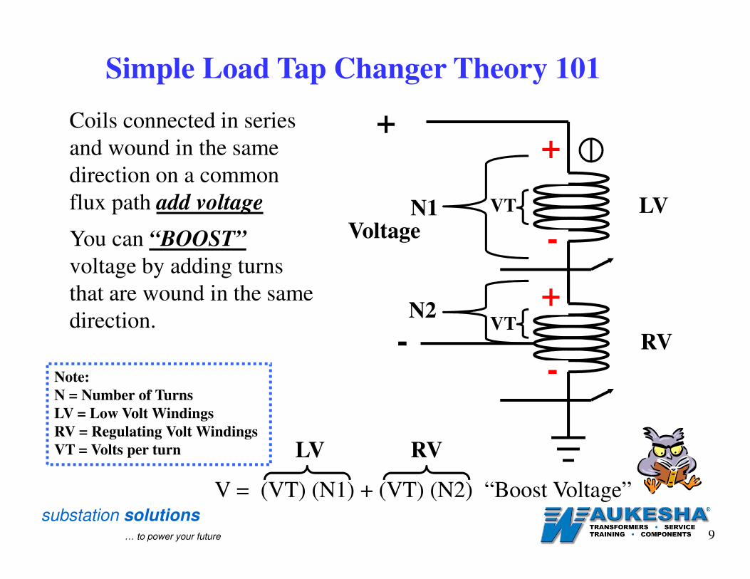
Coils connected in series
and wound in the same
direction on a common
flux path add voltage
You can “BOOST”
voltage by adding turns
that are wound in the same
direction.
VoltageN1
N2VT
VT LV
RV
V = (VT) (N1) + (VT) (N2) “Boost Voltage”
LV RV
Simple Load Tap Changer Theory 101
Note:
N = Number of Turns
LV = Low Volt Windings
RV = Regulating Volt Windings
VT = Volts per turn

substation solutions… to power your future 10
+
-
+
-
-
VoltageN1
N2VT
VT LV
RV
+
V = (VT) (N1) - (VT) (N2) “Buck Voltage”
LV RV
Coils connected in series
and wound in the
opposing direction on a
common flux path
subtract voltage
You can “BUCK” voltage
by adding turns that are
wound in the opposing
direction.
Simple Load Tap Changer Theory 101
Note:
N = Number of Turns
LV = Low Volt Windings
RV = Regulating Volt Windings
VT = Volts per turn

substation solutions… to power your future 11
How does the Load Tap Changer Work
Reactance ~ A reactance LTC utilizes a reactive impedance to
limit the circulating current while in the bridging position. A
bridging position is a normal operating position of a reactance
LTC. Another name for this reactive impedance is a Reactor,
Preventive Autotransformer, or simply a “PA”. This type of LTC
was developed in the United States. They were designed for
higher currents and lower insulation levels due their use in low
voltage regulation. Vacuum interrupter’s were introduced to
reactance LTC’s in 1965.
Resistance ~ Resistive LTC’s are typically designed to arc
either at the selector switch or the transfer (diverter) and operate
at higher speeds. The resistive LTC utilizes a resistor to limit the
circulating current during a tap change. The bridging position is
NOT a normal stopping tap position for a resistive LTC.
There are two basic operating designs of LTC’s.

substation solutions… to power your future 12
How does the Load Tap Changer WorkReactor, Preventive Autotransformer, or simply a “PA”
Reactance type Load Tap Changer
These are
the leads
that will
connect
to the
Load Tap
Changer
substation solutions… to power your future 13
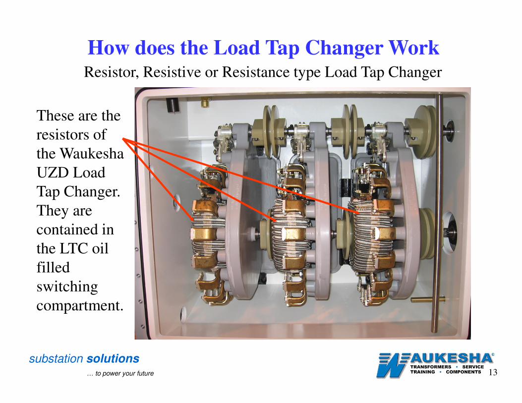
How does the Load Tap Changer WorkResistor, Resistive or Resistance type Load Tap Changer
These are the
resistors of
the Waukesha
UZD Load
Tap Changer.
They are
contained in
the LTC oil
filled
switching
compartment.

substation solutions… to power your future 14
How does the Load Tap Changer WorkResistor, Resistive or Resistance type Load Tap Changer
This is a side picture
of the Waukesha
UZD Load Tap
Changer. During
maintenance, the
resistors should be
ohm’ed and all
hardware should be
checked for integrity

substation solutions… to power your future 15
What are the Functions of the LTC Switches
The On-Load Tap Changer Operation can be divided in up to
three separate functions:
1. Selection of “raise” or “lower” (Boost or Buck) of the
winding taps by use of the reversing switch (if equipped).
2. Selection of voltage magnitude by use of the selector
switch
3. The arc interruption by use of the transfer switch (if
equipped).
The functions are limited to the devices (switches) in the On
Load Tap Changer design.
substation solutions… to power your future 16
There are several different types of reactance load tap changers.
They can be divided into categories by the components or
switches included in their design.
Arcing on the selector switch
Arcing on the transfer / diverter switch
Arcing in a vacuum bottle.
Types of Load Tap Changers
Arcing Reactance

substation solutions… to power your future 17
Reactance Load Tap Changers
Arcing on the Selector Switch
Load Tap Changers that arc on the Selector Switch must have special
contacts that have arcing tips where the moveable contacts make
contact with them. These tips are made of a material called Elkonite
or Copper Tungsten. This material is not a low resistant material.
Examples of these types of On-Load Tap Changers are listed below:
McGraw Edison 550 General Electric LR-38
McGraw Edison 550B General Electric LR-48
McGraw Edison 550C General Electric LR-68
Siemens/Allis TLH-10/20/21 General Electric LR-72
Siemens/Allis TLG Siemens/Allis TLF-20/30
Siemens Allis TLH-10 Siemens/Allis TLS
substation solutions… to power your future 18
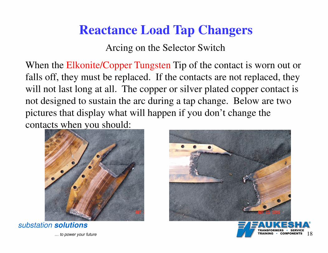
Arcing on the Selector Switch
When the Elkonite/Copper Tungsten Tip of the contact is worn out or
falls off, they must be replaced. If the contacts are not replaced, they
will not last long at all. The copper or silver plated copper contact is
not designed to sustain the arc during a tap change. Below are two
pictures that display what will happen if you don’t change the
contacts when you should:
Reactance Load Tap Changers

substation solutions… to power your future 19
Arcing on the Selector Switch Sequence of Operation
Reactance Load Tap Changers
On Position
(non-bridging)
Selector Switch
Opens
Selector Switch
Closes
On Position
(bridging)
Load Current
Circulating Current

substation solutions… to power your future 20
Arcing on the Transfer / Diverter switch
Some LTC’s are equipped with a transfer or diverter switch. These
switches are designed to sustain the arc of the make and break
operation while changing tap positions. The operation is as follows:
The Transfer/Diverter switch opens and breaks the current; the
selector switch opens with no arc; the selector switch moves to the
next tap position; the selector switch closes with no arc; and the
Transfer/Diverter switch closes and makes the arc. No arc should
occur on the selector switch. Examples of these types of On-Load
Tap Changers are listed below:
Westinghouse UTT Series Westinghouse UTS
General Electric LR-65 & 83 Wagner KRL 14
Federal Pacific TC-546 & 525 Federal Pioneer TC-15
Federal Pioneer TC-23 & 23-2 McGraw Edison 396
Reactance Load Tap Changers

substation solutions… to power your future 21
Arcing on the Transfer / Diverter switch
With the arc occurring on the diverter/transfer switch, the selector
switch contacts could now be made of a low resistance material to
reduce heat on the contact. Below are examples of Diverter/Transfer
switches.
Reactance Load Tap Changers
Westinghouse UTT Series
General Electric LR-83
General Electric LR-65
Federal Pacific TC-546 Diverters
With TC-525 Upgraded
Tap Head, Selector Switch &
Reversing Switch

substation solutions… to power your future 22
Arcing on the Transfer / Diverter Switch Sequence of Operation
Reactance Load Tap Changers
On Position
(non-bridging)
Transfer Switch Opens Selector Switch Opens
Transfer Switch Closes
On Position (bridging)
Selector Switch Closes
Load Current
Circulating Current
substation solutions… to power your future 23
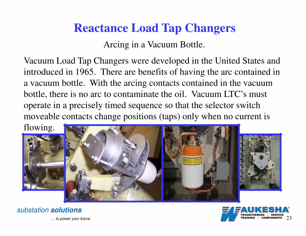
Arcing in a Vacuum Bottle.
Vacuum Load Tap Changers were developed in the United States and
introduced in 1965. There are benefits of having the arc contained in
a vacuum bottle. With the arcing contacts contained in the vacuum
bottle, there is no arc to contaminate the oil. Vacuum LTC’s must
operate in a precisely timed sequence so that the selector switch
moveable contacts change positions (taps) only when no current is
flowing.
Reactance Load Tap Changers

substation solutions… to power your future 24
Arcing in a Vacuum Bottle.
With cleaner oil, the probability of filming is greatly reduced. With
the oil having no carbon particulates, there would be less mechanical
wear. Examples of these types of On-Load Tap Changers are listed
below:
General Electric LRT-200 Reinhausen RMV-A
General Electric LRT300/400/500/700 Reinhausen RMV-1
Federal Pioneer TCV-23 Reinhausen RMV-II
McGraw Edison V2 Westinghouse UVT
McGraw Edison 397D
Reactance Load Tap Changers

substation solutions… to power your future 25
Arcing in a Vacuum Bottle ~ Sequence of Operation
Reactance Load Tap Changers
On Position (non-bridging) By-pass Switch Opens Vacuum Bottle Opens Selector Switch Opens
Vacuum Bottle Closes By-pass Switch Closes
On Position (bridging)
Selector Switch Closes
Load Current
Circulating Current
substation solutions… to power your future 26
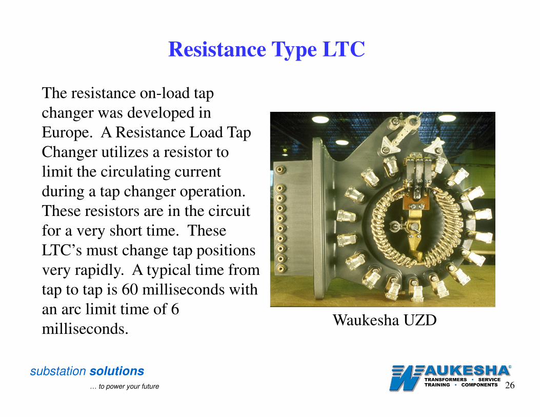
The resistance on-load tap
changer was developed in
Europe. A Resistance Load Tap
Changer utilizes a resistor to
limit the circulating current
during a tap changer operation.
These resistors are in the circuit
for a very short time. These
LTC’s must change tap positions
very rapidly. A typical time from
tap to tap is 60 milliseconds with
an arc limit time of 6
milliseconds.
Resistance Type LTC
Waukesha UZD

substation solutions… to power your future 27
Resistance Type LTC
You should never see a
resistance load tap
changer stopped in the
position displayed in this
picture. This is a
“transition-bridging”
position. The transition-
bridging position must
occur to provide a
“Make-Before-Break”
operation. This
make-before-break
operation is a
requirement of all
on-load tap changers.

substation solutions… to power your future 28
Resistance Type LTCTap Change Sequence of Operation
Transition Bridging
Position
On Position
1 2 3 4
765
On Position
Load Current
Circulating Current

substation solutions… to power your future 29
Simple Transformer Theory 101

substation solutions… to power your future 30
Simple Transformer Theory 101
Typical Layered Windings
Core Steel

substation solutions… to power your future 31
1
2
3
4
5
6
7
8
9
K
M
Regulated
Windings are
covered with
the Secondary
(low voltage)
Windings and
the Secondary
(low voltage)
Windings are
covered with
the Primary
(high voltage)
Windings.This is assuming
that there are NO
tertiary Windings.
Simple Transformer Theory 101
Core Steel

substation solutions… to power your future 32
Simple Transformer Theory 101
+
-
Voltage VT = Volts Per Turn
Current
Magnetic Flux
Volts Per Turn = Voltage / Number of turns

substation solutions… to power your future 33
Simple Transformer Theory 101
Transformer Core
+
+
-
-N1 N2
VTVT V2V1
Note:
N = Number of Turns
I = Current
V = Voltage
VT = Volts per turn
FLUX
V1 = VT * N1
VT = (V1 / N1) = (V2 / N2)
V2 = VT * N2
Ratio = (V1 / V2) = (N1 / N2)
substation solutions… to power your future 34
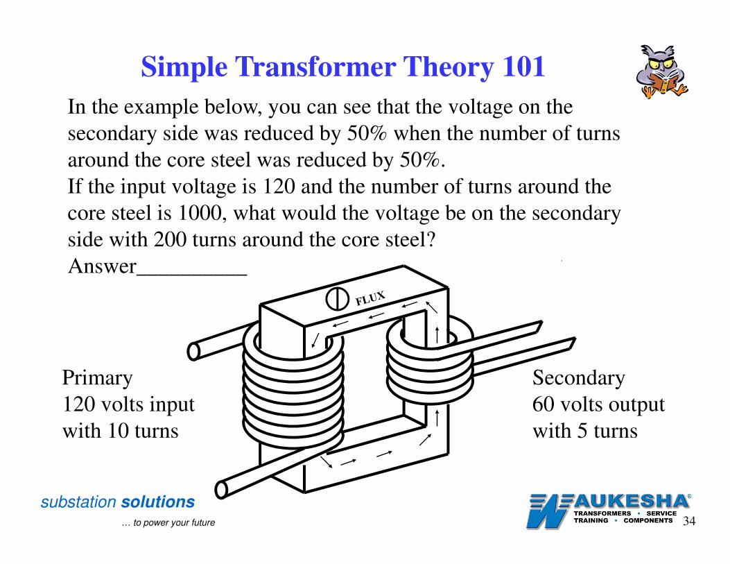
In the example below, you can see that the voltage on the
secondary side was reduced by 50% when the number of turns
around the core steel was reduced by 50%.
If the input voltage is 120 and the number of turns around the
core steel is 1000, what would the voltage be on the secondary
side with 200 turns around the core steel?
Answer__________
Primary
120 volts input
with 10 turns
Secondary
60 volts output
with 5 turns
Simple Transformer Theory 101

substation solutions… to power your future 35
Reversing Switch
Federal Pacific TC-525
Waukesha UZD
Siemens / Allis TLS Reinhausen RMV-II
McGraw Edison 550B

substation solutions… to power your future 36
How does the Reversing Switch Work
A reversing switch (if equipped) located inside the LTC
mechanism, enables the windings to double the number of tap
positions without doubling the number of tap leads from the
tap (regulating) windings. All reversing switches do not
operate the same. There are basically two types of reversing
switches. The most common type is the “Standard Reversing
Switch”. The other type is the “Isolated Reversing Switch”:
also referred to as the “Coarse-Fine Pre-selector”. Both of
these types of reversing switched allow the same function as
noted in bold italic print above. The difference is how they
allow the function to take place. Some manufactures call a
reversing switch a “change-over-selector” switch.
Reversing Switch

substation solutions… to power your future 37
The standard reversing switch swaps the polarity of the
regulating windings. This means that the end of the regulating
winding that is connected in series with the secondary
windings is changed when the reversing switch goes through
neutral. See the diagram below:
Standard Reversing Switch
How does the Reversing Switch Work
N X1
N X1
substation solutions… to power your future 38
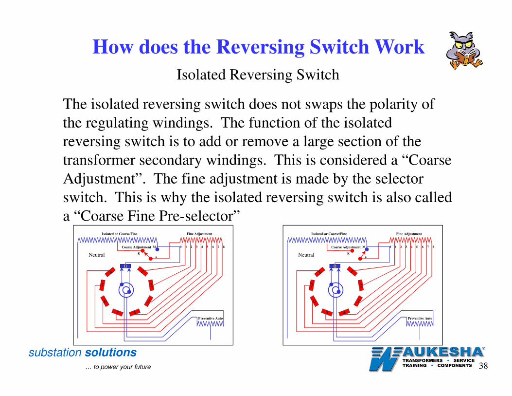
The isolated reversing switch does not swaps the polarity of
the regulating windings. The function of the isolated
reversing switch is to add or remove a large section of the
transformer secondary windings. This is considered a “Coarse
Adjustment”. The fine adjustment is made by the selector
switch. This is why the isolated reversing switch is also called
a “Coarse Fine Pre-selector”
Isolated Reversing Switch
Isolated or Coarse/Fine
Coarse Adjustment
9
M
K
01
2
3
4
8
7
5
6
876543210
Preventive Auto
Neutral
Fine AdjustmentIsolated or Coarse/Fine
Coarse Adjustment
9
M
K
01
2
3
4
8
7
5
6
876543210
Preventive Auto
Neutral
Fine Adjustment
How does the Reversing Switch Work

substation solutions… to power your future 39
Regulated WindingsSecondary Windings
Primary Windings
Isolated Reversing Switch ~ Operation Above Neutral
Watch What
Happens

substation solutions… to power your future 40
Isolated Reversing Switch ~ Operation Below Neutral
Regulated WindingsSecondary Windings
Primary Windings
Watch What
Happens

substation solutions… to power your future 41
“Boosting Power” ~ Standard Reversing Switch
Going Above Neutral
Regulated WindingsSecondary Windings
Primary Windings
Watch What
Happens
Watch What
Happens

substation solutions… to power your future 42
“Bucking Power” ~ Standard Reversing Switch
Going Below Neutral
Regulated WindingsSecondary Windings
Primary Windings
Watch What
Happens
Watch What
Happens
substation solutions… to power your future 43
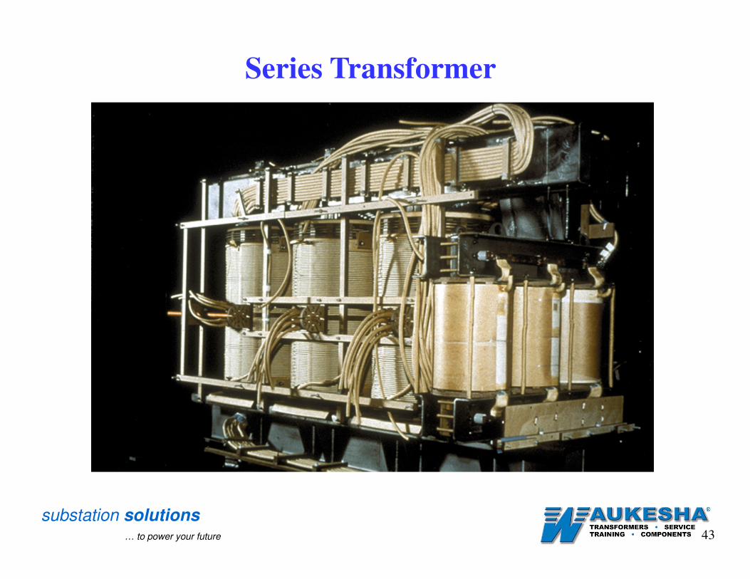
Series Transformer

substation solutions… to power your future 44
Series Transformer

substation solutions… to power your future 45
Series Transformer

substation solutions… to power your future 46
Primary Windings
Series
Transformer
6:1 Ratio
1200 amps200 amps
Reversing Switch
Secondary WindingsRegulating Windings
Load 1200 amps
LTC Rating 600 amps
Supply
Transition
Resistors
Resistance Type LTC
Series Transformer
N X1

substation solutions… to power your future 47
Heating is a problem in LTC’s as heat aids in the filming process.
Filming aids in coking and coking causes failure. Below are pictures
of coking on contacts. If you have coking on contacts, what do you
do? Check for the heat source. It could be from contacts that are
worn and need replacing; unbalanced spring pressure; too little spring
pressure; a weak contact point; a loose connection or other issues that
could cause a hot spot or elevated heating in the LTC oil
compartment.
Coking

substation solutions… to power your future 48
0
10
20
30
40
50
60
70
80
90
100
0
100
200
300
400
500
600
700
800
900
1000
1100
1200
1300
1400
1500
Temperature oC
Rela
tive A
mo
un
t
Ethane Ethylene
Methane Acetylene
Hydrogen
PropylenePropane
Decomposition of N-octane
Dissolved Gas Analysis
Different gases are produced at different temperatures

substation solutions… to power your future 49
Mild Moderate Severe
400-1,500 1,500-20,000 >20,000
600-2,400 2,400-24,000 >24,000
1,500-7,500 7,500-75,000 >75000
<25 >25 >50
Dessicant Breather
Sealed Tank
Vaccum LTC
Problem Severity*
Free Breathing
Tank Design
Gas Levels Of Combined Readings Of Methane, Ethane, and Ethylene in Parts Per Million
Interpretation Of DGA Readings
substation solutions… to power your future 50
Learning the
TERMSfor LTC’s
LTC Terms

substation solutions… to power your future 51
LTC TermsReactor
The reactor may also be referred to as a "PA, preventive auto or
preventive autotransformer". The reactor serves as a current limiting
device when the LTC is sitting on a bridging (odd number) tap
position or passing through a bridging (odd number) tap position.
Bypass Switch
The bypass switch is used to shunt current away from the
selector switch to a vacuum interrupter so the selector switch
can switch taps without arcing. Bypass switches are almost always found on vacuum LTC's only.
Preventive Autotransformer (PA or Preventive Auto)
The preventive autotransformer may also be referred to as a
"reactor". The preventive autotransformer serves as a current
limiting device when the LTC is sitting on a bridging (odd
number) tap position or passing through a bridging (odd number) tap position
substation solutions… to power your future 52
LTC TermsSpring Drive
The spring drive may be either a single spring or a bank of
springs that are utilized to change from one tap to another. A
hand crank or a motor charges the spring battery. When the
spring drive is fully charged, the mechanism then releases
the energy contained in the spring drive to allow the change of tap positions.Full Cycle Position
A Non-bridging position in an LTC. Both or all moveable
selector contacts of the selector switch are on the same
stationary contact. Half Cycle Position
A Bridging position in an LTC. The moveable selector
contacts of the selector switch are on separate (different)
stationary contacts.
substation solutions… to power your future 53
Selector Switch
The selector switch is used to determine the tap voltage
(select the voltage magnitude) the transformer operates at
and supplies to the load.
LTC Terms
Reversing Switch (change over switch)
There are two different types of reversing switches, standard
and isolated. Both types of the reversing switch allow the
number of tap positions to be doubled without doubling the
number of tap leads coming out of the windings. While the
standard reversing switch swaps the polarity of the tap
windings, the isolated reversing switch changes a large
section of the secondary windings in or out of the circuit.

substation solutions… to power your future 54
LTC Terms
Connection Diagram of a Typical Load Tap Changer with a
Standard Reversing Switch Used To Swap Polarity (Without a
Series Transformer)
Standard Reversing Switch
The standard reversing switch is used to swap the polarity of the tap
winding in order to raise (boost) or lower (buck) voltage.
substation solutions… to power your future 55
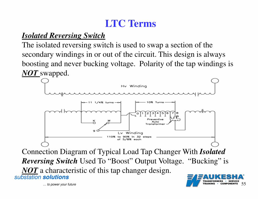
LTC TermsIsolated Reversing Switch
The isolated reversing switch is used to swap a section of the
secondary windings in or out of the circuit. This design is always
boosting and never bucking voltage. Polarity of the tap windings is
NOT swapped.
Connection Diagram of Typical Load Tap Changer With Isolated
Reversing Switch Used To “Boost” Output Voltage. “Bucking” is
NOT a characteristic of this tap changer design.

substation solutions… to power your future 56
LTC Terms
Reactance (Reactive)
Reactive LTC’s are typically designed to arc either on the selector
switch, the transfer (diverter) switch, or the vacuum interrupter.
They typically operate at relatively slow speeds (1 - 3 seconds). The
reactive LTC utilizes a reactor or preventive autotransformer to limit
the circulating current during a tap change and or when in the
bridging position. The bridging position is a normal stopping tap
position for a reactive LTC.
A vacuum tap changer is a reactive type LTC.
Two Basic Types of LTC’s

substation solutions… to power your future 57
LTC Terms
Resistance (Resistor)
Resistive LTC’s are typically designed to arc either at the selector
switch or the transfer (diverter) and operate at higher speeds (.3 - .7
seconds). The resistive LTC utilizes a resistor to limit the
circulating current during a tap change. The bridging position is
NOT a normal stopping tap position for a resistive LTC.
Two Basic Types of LTC’s

substation solutions… to power your future 58
Transfer Switch
The transfer switch may also be referred to as the “Diverter
Switch”. The transfer switch is used to interrupt the load so the
selector switch can change position without arcing. The transfer
switch contacts are made of an arc erosion resistant material called
Elkonite (copper-tungsten) and is designed to arc (not heat) under
normal conditions
LTC Terms
Transition Resistor
A resistor that is used to limit the circulating current during
transition only from one tap position to another. The transition
resistor is only utilized in transition. The transition resistor is not
designed to carry full load current for any long period of time. The
Transition resistor is found on a resistance type LTC.

substation solutions… to power your future 59
LTC TermsStationary Contact
A contact that is fixed in position. (Stationary Selector)
Moving Contact
A contact that is not fixed in position. A contact that is allowed to
change positions. (Moving Selector)
Reversing Contact
This contact is associated with the reversing switch of an LTC
mechanism. (See Stationary Contact and Moving Contact for definition of term).
Neutral Position
The neutral position is the position where the LTC is neither
bucking nor boosting voltage and / or where the tap windings are
not in the circuit. This is nominal position.
substation solutions… to power your future 60
Questions?