best available copy - defense technical information center · illustrations figure tr 68-20...
TRANSCRIPT

BEST AVAILABLE COPY

TECHNICAL REPORT NO. 68-20
LONG-PERIOD TRIAXIAL SEISMOGRAPH DEVELOPMENT Quarterly Report No. 7. Project VT/6706
by
B. M. Kirkpatrick
Sponsored by
Advanced Research Projects Agency Nuclear Test Detection Office
ARPA Order No. 624
Availability
Qualified users may request copies of this document from:
Defense Documentation Center Cameron Station
Alexandria, Virginia 22341
GEOTECH A TELEDYNE COMPANY 3401 Shiloh Road Garland, Texa'
4 June 1968
- —

IDENTIFICATION
AFTAC Project No: Project Title: ARPA Order No: ARPA Program Code No; Name of Contractor:
Date of Coatract: Amount of Contract: Contract Number: Program Manager:
VELA T/6706
Long-Period Seismograph Development
6F10
Geotech, A Teledyne Company Garland, T^xas 15 June If 66 $246,713 AF 33(657)-16406 David B. Andrew BR 1-2561, Area Code 214

CONTENTS
ABSTRACT
1 • INTRODUCTION
4.
APPENDIX - Statement of work to be done
-i-
Page
2- SS^A8™0'THEL0NG-PERI0DTRIAXIALB0R^LE
^ SE^TETTA^I:1™ ^ L0NG-PERIÜD TRIAXIAL ™™™ 3.1 Response to artificially induced surface tilt 3.2 Response to wind and barometric pressure change 3.3 Multiple coherence and spectral plots
o^ATI0N m MODIFICATION OF THE LONG-PERIOD TRIAXIAL BOREHOLE SEISMOMETER, TASK le BIAXIAL
2
8
TR 68-20
. ,. _

ILLUSTRATIONS
Figure
TR 68-20
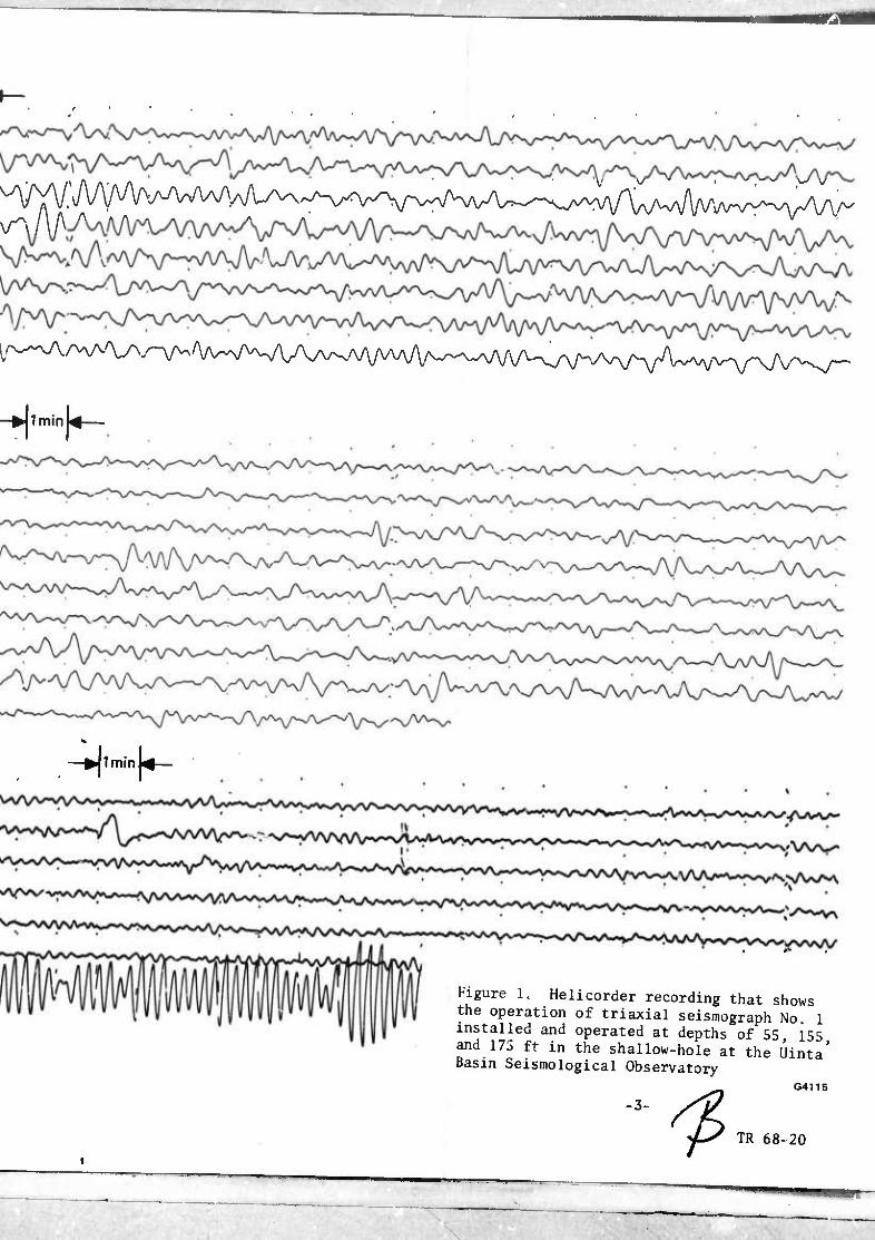
Helicorder recording that shows the operation of triaxial seismograph No. 1 installed and operated at depths of 55. 155 and 175 ft in the shallow-hole at the Uinta Basin Seismological Observatory
Seismogram showing a portion of a teleseismic event < demonstrating the operational agreement between the transformed triaxial traces (triax sum, ZCT, NCT, ECT) and the advanced long-period traces (ZLPo, NLPo 'ELP->) (X5 enlargement of 16 millimeter film)
Empirical amplitude response curve for the long-period s triaxial borehole seismograph No. 1 operating in the 200 foot deep test borehole at Uinta Basin Saismological Observatory (UBSO) &*■<-*■*■
w^i?al phaSe resPonse curve for the long-period triaxial 6 borehole seismograph No. 1 operating in the 200 foot deep test borehole at Uinta Basin Seismological Observatory (UBSO)
Seismogram illustrating the relative responses of the 9 long-period triaxial (TjLP. T2LP, T3LP) and the advanced long-period seismograph systems (ZLPo, NLPo. ELP-O as operated at UBSO, to artificially induced surface tilt CX10 enlargement of 16 millimeter film)
Seismogram illustrating the relative responses of the 11 long-period triaxial (T^P, T2LP, T3LP) and the advanced long-period seismograph systems (ZLPo, NLPo, ELPo) as operated at UBSO, to barometric pressure change (trace ML2) accompanied by low wind (trace WI) (X10 enlarger.nt of 16 millimeter film)
Seismogram illustrating the relative responses of the 12 long-period triaxial (TiLP, T2LP, T3LP) and the advanced long-period seismograph systems (ZLP2, NLP2, ELP-,) as operated at UBSO, to a large barometric pressure change (trace ML2) accompanied by gusting winds (trace WI) (X10 enlargement of 16 millimeter film)
-11-

Figure
ILLUSTRATIONS. Conrin..^
Sexsmogram xllustrating the relative responses of the ong-perxod tnaxial (TUP. T2LP. T3LP) and the advanced long-period seismograph systems (ZLP2. NLP2. ELP2) äs operated at UBSO to barometric pressure changes' trace ML2) accompanied by winds gusting above 30 mph (trace WIl (X10 enlargement of 16 millimeter film)
13
Table
*********** *****^
TABLES
Empirical amplitude response data for the long-period triaxial and advanced long-period seismographs at the Umta Basin Seismological Observatory obtained on 19 February 1968 and 1 March 1968 respectively
Empirical phase response for the long-period triaxial and advanced long-period seismographs at the Uinta Basin Seismological Observatory obtained on 28 Februaiy 1968
■in-
TR 68-20

ABSTRACT
Field testing of the long-period triaxial seismometer has continued at the
artmc^n Seir1°giCal Observatory CUBSO). The results of tests involving
P^ss^re^^te^p^e^r^ reSPÖnSe 0f the ^^ t0 ^ ^ ^^
TR 68-20
■P

LONG-PüRIOD TRIAXIAL SEISMOGRAPH DEVELQPMRNT
1. INTRODUCTION
This report describes the work performed by Geotech. A Teledvne Comnanv in
IwJtL %ll ^f6 Te?nical Applications Center (AFTAC) and the overall dxrectxon of the Advanced Research Projects Agency (ARPA). overall
This report discusses the progress made on the development of a long-period fLPl
9 t^r™^ aSedperod corred 'y this rep°rt extends ^vniLy3
lyoa to 31 March 1968 and deals mainly with the field operation of the Ion*- period triaxial seismograph at the shallow-hole test facility located at the Uinta Basin Seismological Observatory (UBSO) and the redesign of an improved tnax module at the Garland plant. improved
2- PRELIMINARY TESTING OF THE LONG-PERIOD TRIAXIAL SEISMOMETER. TASK 1c
The seismograph utilizing the Model 26310 long-period triaxial seismometer has been operated at three specific depths in ?he shallow hole during this
nositS/r10^ • ^ ^'fiVe 0Perati0"al improvement *s the seismometer was positioned lower in the hole is illustrated in figure 1. The three separate samples reflect operation of seismometer module No. 1 at depths of 55^115 and ZUll: TKf «^^b^kground level of the bottom trace illustrated agrees quite favorably with the advanced long-period system (ALPS) operating at Sso
An^or.0Per-ti0n 0f th! seismograPh by UBSO personnel began on 24 January 1968 ta? on ^a"Sf0rmatl°n ^/he triaxial data to a horizontal and vertical presen tation is being performed at the site in an effort to confirm proper operation of the tnax seismograph. This is illustrated in figure 2 which Shows the
Z^crLd^ESr'H'r6^ the C00rdinate ^foSSd triaxial Uriaxs^. ZCT NCT and ECT) and the advanced long-period seismograph (ZLP. NLp9 and
^ £ f^f S- Ihe figUre iS Present^ at X5 instead of X10 enllrgeSt o?
^fLi?io;s0fX^?how raore operation of the systems- For ^ ™»™.
TJ™i*lle*t flgUreS are about 25K at 25 sec- The fi«u^ shows th^ response of the systems to a teleseismic event with the triaxial seismometer positioned at the 175 ft level in the 200 ft deep hole. The agreement between the systems is obvious when the triax sum and the transformed Vertical trice
iscoZLT?^ t0. the ^dVanCed VertiCal (ZLP2)' the transformed north (NCT) tnJ^tt 11 ! advanced north (NLP2) , and the transformed east ^ECT) is compared to the advanced east (ELP2). y. j ^
System amplitude and phase responses were taken and minor adjustments were necessary in order to provide matched responses. Figures 3 and 4 show the
-1-
TR 68-20
=s—•

amplitude and phase response curves for triax seismograph No 1 The oth,. ^
a^Utuda and phase Ja^tL ^ll«^^^'^ ALPS n0r"all"d
3. FIELD MEASUREMENTS WITH THE LONG-PERIOD TRIAXIAL BOREHOLE SEISMOMETER. TASK Id
3.1 RESPONSE TO ARTIFICIALLY INDUCED SURFACE TILT
The fonowin, „hie gives th. ^^1'™%] r^t^TSr-
Time Run # Begin
0050
End
0051
(mph) Direction
1 0.5 South to North
2 0055 0056 2.5 North to South
3 0058 0059 10.0 South to North
4 0100 0101 14.0 North to South
Since the advanced LP vault is located generally south of the triaxial install* tion the south-to-north runs are detected first by the ALPS fZLPmD i ELP2) and next by the triaxial (T^P, T2LP. and T^LPS In 1hl toVth tn'' ^ run.«, the order of detection is reversed. 3 J • m the north-to-south
tilt1^ bTÄ ^^^^^-"P^-S0' I6 tWO ^"^ t0 SUrfaCe
them to their coordWt^Ä vertical seismograph ZLP-^ can be romnared tn 7rT. i-v,/^ 1 I aa.anced be cempared to NV and the ^^^t ELpfLt c'Zrfd Te'^^t S" »,l\ "I '^ fig;re that althou8h the "i""1 ahowed sZe äpensf io L
tr.i.Tsr'thTSv^VL^r-0^rtT^tl1''F^
»ents NLP2 and ELP2 showed the pZlT r^oV^s ^f^tT*1 i"StrU-
TR 68-20

f\ —*>|lminU—
ISA Triax Seismograph No. 1 Direction ■ North Mag*12K@i25sec Depth 55 ft
,/w^vv\AA7ww/\^vy\/^^
Vs^Vv^-AA,^/^]
" riax Seismograph No. 1 Direction - North Mag«= 12K@25sec Depth 115 ft
Triax Seismograph No. 1 Direction - North Mag* 12K@25sec Depth 175 ft
"A/^w
-JlminL—
—►jlminU—
Figure 1. Helicorder recording that shows the operation of triaxial seismograph No. 1 installed and operated at depths of 55 155 and 175 ft in the shallow-hole at the Uinta' Basin Seismological Observatory
-3-
^
G4115
TR 68-20
—•—^—■ i ■ ■ ■ .. ■

TRIAX 1 25.2K @ 25 SEC
TRIAX 2 TRIAX 3
24.3K®25SEC 28.1 K@ 25 SEC
TRIAXSUM ZLP2
27.5K ® 25 SEC 25.0K @ 25 SEC
2CT NLP2
26.0K ® 25 SEC 25.0K @ 25 SEC
NCT «30.0K ® 25 SEC ELP2 23.0K @ 25 SEC ECT
WIND _
as24.2K®25SEC 3 mph = 0.5 mm
S = 0/^) mm (E = 3 mm)
UBSO RUN 059 28 FEBRUARY 1968
——^

<V^:
^TS^A^^^
Figure 2. Seismogram showing a portion of a teleseismic event demonstrating the operational agreement between the transformed triaxial traces (triax sum, ZCT, NCT, ECT) and the advanced long-period traces (ZLP2, NLP2. ELP2)(X5 enlarge- ment of 16 millimeter film)
G4116
TR 68-20
-4-
^

SIGNAL GENERATOR H-P 203A
LP TRIAX SEIS
MOD 26310
PTA Tg=110 sec MOD S240A
PTA POWER
SUPPLY MOD 14486
SIGNAL CONTROL CENTER MOD
23403-M1
HELI- CORDER
MOD 2484
4_
1.0
f« L_
| t-t
:::=^ ^
L _ I / \
f / \
i /
0.1 /
\ WM fH .-. \ ■
19
1
Feb fG/2
1
ruary 19 äoo-n
i i i
68
1 1
10 inn PERIOD (sec)
Figure 3. Empirical amplitude response curve for the long-period triaxial borehole seismograph No. 1 operating in the 200 foot deep test borehole at
Uinta Basin Seismological Observatory (UBSO)
G3806
TR 68-20
,., ,.

VARIABLE PHASE OUTPUT
SIGNAL GENERATOR HP 203A
LP TRIAX SEIS
MOD 26310
PTA Tg=110 sec MOD S240A
PTA POWER
SUPPLY
MOD 14486
SIGNAL CONTROL CENTER
MOD 23403-M1
OSCILLO- SCOPE
TEKTRONIX 502
PERIOD (sec) 100
28 February 1968 BWG/2800-14
Figure 4. Empirical phase response curve for the long-period triaxial borehole seismograph No. 1 operating in the 200 foot deep test borehole
at Uinta Basin Seismological Observatory (UBSO)
G3806
-6- TR 68-20

Table 1. Empirical amplitude response data for the long-period triäxial and advanced lonq-oeriod
ajSl&^^g; Seism°1°^ca1 ^ervatory obtained on 19 FebSy^^
T1LP
Period (sec)
100 0.043
80 0.090
60 0.206
bO 0.336
40 0.562
30 0.922
25 1.0
20 0.721
16.7 0.432
15
12.5 0.108
10
T LP 2
0.049
0.090
0.225
0.364
0.601
0.961
1.0
0.748
0.457
0.108
T3LP ZLP,
Relative amplitude
0.042
0.0&7
0.202
0.336
0.555
0.942
1.0
0.722
0.432
0.108
0.065
0.149
0.310
0.465
0.710
0.975
1.0
0.755
0.352
0.0745
2
0.0568
0.124
0.253
0.364
0.568
0.927
1.0
0.817
0.379
0.071
ELP
0.0554
o.no 0.238
0.353
0.568
0.865
1.0
0.853
0.379
0.088
Table 2. Empirical phase response data for the long-period triaxial and advanced long-period seismographs at tue Uinta Rasin >;oicmninnf^»i nKc„„..,*«„.. »^-^"J .. oou"? Per ,.
¥P T2LP T3LP
uusci Yakurjr uu
ZLP2
-a 1 neu on ca rei
NLP2
)ruary isbt
ELP2
Period (sec) 0° r r r 0° r 12.5 -192 -210 -210 -198 -240 -237
16.7 -161 -161 -154 -141 -172 -167
20 -110 -108 -103 - 93 -112 -106
25 - 38 - 37 - 27 - 31 - 33 - 29
30 22 18 31 19 35 30 40 97 95 105 91 96 103 50 143 139 147 137 138 146 60 173 171 179 166 172 178 80 209 209 215 211 212 213
100 243 245 249 251 246 248
-7-
TR 68-20
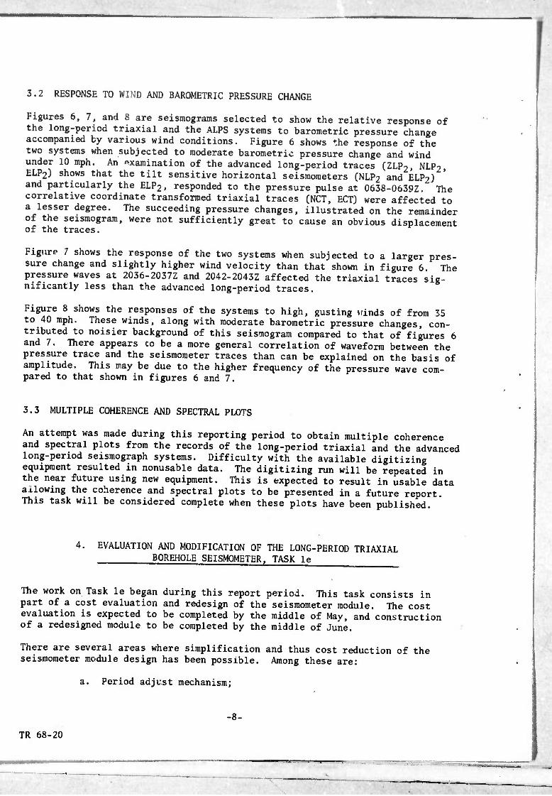
3.2 RESPONSE TO WIND AND BAROMETRIC PRESSURE CHANGE
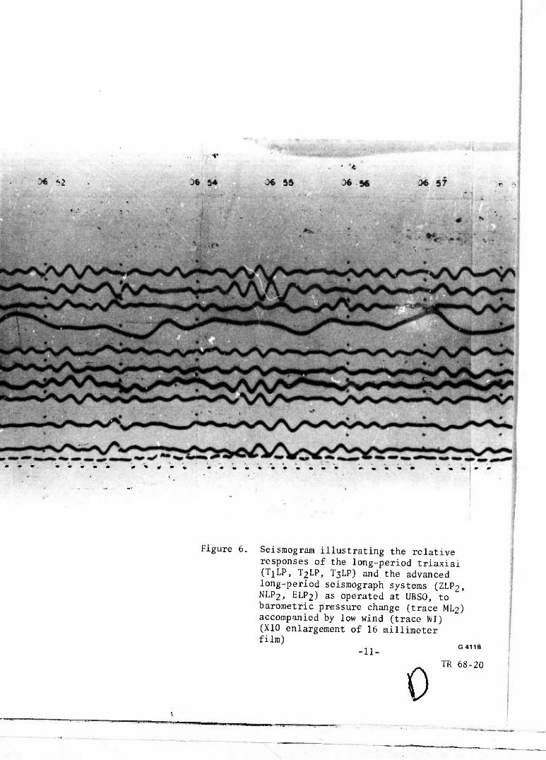
Figures 6, 7, and 8 are seismograms selected to show the relative response of the long-period triaxial and the ALPS systems to barometric pressure change accompanied by various wind conditions. Figure 6 shows the response of the two systems when subjected to moderate barometric pressure change and wind under 10 mph. An examination of the advanced long-period traces (ZLPT, NLPO, ELP2) shows that the tilt sensitive horizontal seismometers (NLP2 and ELP2) and particularly the ELP2, responded to the pressure pulse at 0638-0639Z. The correlative coordinate transformed triaxial traces (NCT, ECT) were affected to a lesser degree. The succeeding pressure changes, illustrated on the remainder of the seismogram, were not sufficiently great to cause an obvious displacement of the traces.
Figure 7 shows the response of the two systems when subjected to a larger pres- sure change and slightly higher wind velocity than that shown in figure 6. The pressure waves at 2036-2037Z and 2042-2043Z affected the triaxial traces sig- nificantly less than the advanced long-period traces.
Figure 8 shows the responses of the systems to high, gusting winds of from 35 to 40 mph. These winds, along with moderate barometric pressure changes, con- tributed to noisier background of this seismogram compared to that of figures 6 and 7. There appears to be a more general correlation of waveform between the pressure trace and the seismometer traces than can be explained on the basis of amplitude. This may be due to the higher frequency of the pressure wave com- pared to that shown in figures 6 and 7.
3.3 MULTIPLE COHERENCE AND SPECTRAL PLOTS
An attempt was made during this reporting period to obtain multiple coherence and spectral plots from the records of the long-period triaxial and the advanced long-period seismograph systems. Difficulty with the available digitizing equipment resulted in nonusable data. The digitizing run will be repeated in the near future using new equipment. This is expected to result in usable data allowing the coherence and spectral plots to be presented in a future report. This task will be considered complete when these plots have been published.
4. EVALUATION AND MODIFICATION OF THE LONG-PERIOD TRIAXIAL BOREHOLE SEISMOMETER, TASK le
The work on Task le began during this report period. This task consists in part of a cost evaluation and redesign of the seismometer module. The cost evaluation is expected to be completed by the middle of May, and construction of a redesigned module to be completed by the middle of June.
There are several areas where simplification and thus cost reduction of the seismometer module design has been possible. Among these are:
a. Period adjust mechanism;
-8-
TR 68-20
•* ■ 1—

UBSO 13 Mar 68 073-68
TUP 46.5K @ 25 sec
T2LP 54.3K @ 25 sec
T3LP 45.1K@25sec
ML2 1.19 jUb/mm
ZLP2 68K ® 25 sec
ZCT 48K 9 25 sec
NLP2 48K ® 25 sec
NCT s»42K@25sec
ELP2 52K @ 25 sec
ECT * 55K 9 25 sec
Wl 3 mph = 1 mm S = 0&8, E = 6mm

.
,■

■
Figure 5. Seismogram illustrating triaxial (TiLP, T2LP, T mograph systems (ZLP2, . artificially induced su 16 millimeter film)
b

Figure 5. Seishiogram illustrating the relative responses of the long-period triaxlal (TiLP, T2LP, T3LP) and the advanced long-period seis- mograph systems (ZLP2, NLP2, ELP2J, as operated at UBSO, to artificially induced surface tilt (X10 enlargement of 16 millimeter film) G4117
-9-
TR 66-20
D

— ^——^_____
b. Mass locking mechanism;
c. Tilt tables and tilt table drive;
d. Auxiliary mass mechanism;
e. Motor type;
f. Control circuitry.
The period adjust mechanism has been redesigned to provide a linear period change versus motor "run time." This design is contrasted with the former de- sign in which only a short motor run was required to change the seismometer free period 1 second at the longer periods, and a long motor run was required at the shorter periods. This made the amount of any period change difficult to predict since the period change motor "run time" relationship was only gen- erally known. The new design mechanism should make it possible to adjust to the required free period from a particular value in a minimum of Mae and to a much higher precision than before. A model of the redesigned period adjust mechanism has been completed and is in the process of being tested.
There has been a substantial simplification of the mass locking mechanism made possible through redesign. This will reduce the cost of the mechanism compared to the former more complex uesign. All of the important features of the initial design, which contributed to the protection of the seismometer suspension during shipment and installation, have been retained. Thus, it is expected that the redesigned module will be as transportable as the experimental units now oper- ating at UBSO. ^
Additional redesign effort has been directed toward elimination of the relatively complex and expensive auxiliary mass mechanism (used to control mass position). Mass position of the improved module is to be controlled by a more sensitive leveling method in which leveling in the sensitive axis is controlled by a pro- portional servo, rather than the contactor servo formerly used. Tlius, the num- ber of motors required to control the seismometer module has been reduced to those which level the seismometer and adjust the free period.
A considerable amount of effort has been made to select a motor to dri/e the various mechanisms which permit remote adjustment of the seismometer modules. A small inexpensive stepping motor has been found which promises to solve the motor selection problem. This motor has been subjected to environmental tests while operating at its maximum rated torque and so far appears to satisfy the requirements. Since this motor is, in effect, a brushless dc motor, it retains the iu?h torque characteristics of a dc motor while also exhibiting the relia- bilit/ of the ac motors formerly used.
The stepping motor selected lends itself to digital control since it responds to dc pulses. In the case of the period adjust motor, these pulses are gen- erated uphole, while the leveling motors (which include the mass position motor) are controlled from pulses generated downhole. The period adjust stepping motor combined with the linearized period adjust mechanism, will allow a precision adjustment of the free period since a discrete number of pulses can be used to adjust the free period a predictable amount.
■10-
TR 68-20
■ -L" ■ ■ ■

-^-*x "<W
UBSO 14 it/larch 68 0V4-68
06 37 J6 39
M 5^1 min -—M
06 40 36 41
Ti LP 46.6K @ 25 sec
T2LP 55.3K @ 25 sec
T3LP 46.0K @ 25 sec
ML2 3.58 /Lib/mm
ZLP2 52.0K ® 25 sec
ZCT 50.2K @ 25 sec
NI-P2 50.0K @ 25 sec
NCT a50.0K@25sec
ELF2 50.0K@25sec
ECT *:50.0K@)25sec 3 mph = 1 mm
S = 0/8mm (E = 6mm) . . - - - .
■"■ ■ ii ,■-

41
.
36 42 06 44 06 45 3« 46
•
36 «*
^

■
■
46
. J*'
D6 «7 ^€ f§
I
:* ^c 36 5 M a
•
C/
:* *z 34 5* 0« 55
.
• 'A
* 5« 3« sr r
Figure 6. Seismogram illustrating the relative responses of the long-period triaxial (TiLP, T2LP, T3LP) and the advanced long-period seismograph systems (ZLP2, NLP2, ELP2) as operated at UBSO, to barometric pressure change (trace ML2) accompanied by low wind (trace WI) (X10 enlargement of 16 millimeter film)
-11- G4118
0 TR 68-20

UBSO 15 Mar 68 075-68
TlLP 46.6K @ 25 sec
T2LP 40.7K @ 25 sec
T3LP 46.0K @ 25 sec
ML2 3.58 jUb/tnm
ZLP2 36.0K @ 25 sec
ZCT 46.7K 9 25 sec
NLP2 54.0K @ 25 sec
NCT «50.0K@25sec
ELP2 54.0K @ 25 sec
ECT w 54.0K @ 25 sec
Wl 3 mph = 1 mm
♦ ,
• •» »A mm 20 it mm
S = 0/8mm (E = 6mm) ■
'»
* -j». 1
"

I# • <*
• %
20 43 ft«
t
•4i
^

/
»4l •«• ** m* mm mm
o ~- • '•■"' .■»-

mm m a » M • •* mm
Figure 7. Seismogram illustrating the relative responses of the long-period triaxial (TiLP, T2LP, T3LP) and the advanced long-period seismograph systems(ZLP2, NLP2, ELP2), as operated at UBSO, to a large barometric pressure change (trace MI^J accompanied by gusting winds (trace WI) (X10 enlargement of 16 millimeter film)
0 411! -12-
TR 68-20

02 02 6 02 17 Ji
14 March 68 074-68
TTLP 46.6K @ 25 sec
T2LP 55.3K @ 25 sec
T3LP 46.0K @ 25 sec
ML2 3.58 jUb/mm
ZLP2 52.0K @ 25 sec
ZCT 50.2K @ 25 sec
NLP2 50.0K ® 25 sec
NCT m 50.0K @ 25 sec
ELP2 50.0K ® 25 sec
ECT « 50.0K @ 25 sec
Wl 3 mph = 1 mm
S = 0/8mm (E = 6mm) • • •
* • % »
—

02 19
ÜJb&y*
^

-
I 24 M W ? 2« 2 2f » H ?« 30 ,32 s;
5

- ' » . . ' '
Figure 8. Seismogram illustrating the relative responses of the long-period tri- axial (TjLP, T2LP, T3LP) and the advanced long-period seismograph systems (ZLP2, NLP2, ELP2), as operated at UBSO, to barometric pressure changes (trace ML2) accompanied by winds gusting above 30 mph (trace WI) (X10 enlargement of 16 millimeter film) c
-13- TR
0 4120
68-20

The stepping motor as used to level the seismometer in the sensitive axis will be control ed by a variable pulse-rate oscillator. The rate of the oscil- lator is controlled by the mass position monitor, and is proportional to the error in the mass position, approaching zero as the mass approaches ero
tevell^h the leVeling CirCUit reSUltS in the tnt tab^s automatica ly leveling the seismometer suspension so that the final position of the mass approaches zero. Any correction required in the mass position is accompHshed by reactivating the leveling circuits. accompusned
The control circuitry using the new motor has been designed and the variable
and'te^d £ '^f t0 COntr01 the leVelin* m0tor 'as been breadboard^ ln\llf ""^u1 circuitry has b^n significantly simplified compared to the former one. as has been the uphole control unit. This has resulted in a reduction in the number of conductors required between modules, as weH as those running to the surface.
The practical result of the redesign, as it is now seen, is expe ted to show
nUsW whH ^^ CT reduction- Th" ^ thought to have bee"acco:- plished while maintaining the quality c performance of the triaxial system now being operated at UBSO. ±***.*J. system
-14-
TR 68-20
Si
"— ■ .. .,

APPENDIX to TECHNICAL REPORT NO. 68-20
STATEMENT OF WORK TO BE DONE

EXHIBIT "A" STATEMENT OF WORK TO BE DONE
AFTAC Project Authorization No. VELA T/6706
1. Tasks: 1 - i,'irtl( 196D
•' Experimental Investigation of Thermal Noise rrt„n„,.- fcv mental Instigation, defined inTroiect VT/Q72 nf'^f ^ . he exPeri-
by the Natlona! Bureau uf Standard, "f"'/^'""^/^.'?". iX""
ä Si—''«- -- =-- MA- ■ In "M, hr^T1"* 0f i Lon^-ppriod aiSSÜLJ ggreuole lats r Modify the Melton long-period triaxial seismometer developed ander Pröfect VT/Q72 to adapt it for routine operation in shallow (200.foot) boreholes Reluct the seismometer's diameter so it will fit inside standard 13.375!inch out! side diameter shallow-well casing. Develop and add a suitable lev2?a!n«^ end remotely-controlled levelling device. suitabte level sensor
Prep^e rfJ^SmS^g 0.f the Lo^-Pertod MSSte |g£^Lg Seismom.t.r, prepare a cased, shallow borehole at a VELA seismological observatorv tö
for ins?^;^ b^the fTAC P10JeCt 0fflCer- Assemble hanging equJp^? for installing the seismometer. Conduct preliminary tests «f fch. «Su« A instrument in the test hole to determine its sSuitJ and the e?f^s of temperature and local tilting as functions of depth. Through the use of improved installation techniques, selective filterlna TJliZ <
ÄSSc «s:.10"I00 "c "rlod b8"d i8 u*"'d «* S X^
zizzzi.:'the tri"ui borehou "'s™""""; «-^rd0^:^ 2. Data Requirements; Provide report as specified by DU Form U23. with Attachment 1 thereto.
^ 0p\3Cv AF 33(657)-l6^06
■- ^

Attachment 1 to DD Form 1^23 REPORTS
AFTAC Project Authorization No. VELA T/6706
1. General; Provide monthly, quarterly, final, and special reports in accordance with sentence 1, paragraph 1 of Data Item S-17-12,0, AFSCM 310-1; however, if that data item conflicts with the instructions of paragraph 2 below, the latter will take precedence.
2. Reports;
a. Monthly Status Reports. A monthly letter-type status report in 16 cöpie«, summarizing work for the calendar month, will be submitted to AFTAC by the 5th day of the following month. Each report will be iden- tified by the data listed in paragraph le and will include, but not be limited to, the following subject areas:
(1) Technical Status. Include accomplishments, problems encountered, future plans, actions required-by the government, and appropriate illustrations and photographs.
(2) Financial Status. The contractov will follow the provisions of Data Item A-15-17.0, AFSCM 310-1A (Cost Planning and Appraisal Unit) in submitting financial data.
For the last month of each report period cov^ied by a quarterly progress report, the monthly status report need include only the financial informa- tion
b' Quarterly Progress Reports. Quarterly progress reports-in 50 copies, summarizing work for 3-month periods, will be submitted to AFTAC within 15 days after the close of each such period. Each report will be identified by the data listed in paragraph 2e and will include the notices listed in paragraph 2f. Each report will present a precise and factual discussion of the technical findings and accomplishments for the entire report period, using a formic similar to that of the final reports under Contract AF 33(657)-9967, a« well as the technical information ordinarily required in the monthly reports.
c- Final Reports. T^e final report on Task la will be submitted in 50 copies to AFTAC within 60 days after work on that project is completed- the final report on the remaining tasks will be submitted in 50 copies within 60 days after the completion of all work. Each report will be identified by the data listed in paragraph, 2e and will include the notices listed in paragraph 2f. Each report will present a complete and factual discussion of the technical findings and accomplishments of the project tasks, using the quarterly-report format,
d. Special Reports.
(1) Special reports of major events will be forwarded by telephone telegraph, or separate letter as they occur and should be included in the *
-riot* ^pRoOVjC AF 33(657)-l6406
■•>■■'

following monthly report. Specific items are to Include, but are not restricted to program delays, program breakthroughs, and changes in funding requirements. ö
(2) Special technical reports may be required for instrument evaluations, project recommendations, and special studies when it is more desirable to have these items reported separately from the quarterly cr final reports. Specific format, content, number of copies, and due dates will be furnished by this headquarters.
(3) All scismogramsand operating logs, including pertinent information concerning time, date, type of instruments, magnification, etc., will be provided when requested by the AFTAC project officer*
^ ^entification Data. All monthly, quarterly, and final reoort« will be identified by the following data: reports
AFTAC Project No. VELA T/6706.
Project Title.
ARPA Order No. 624.
ARPA Program Code No. 6Flv7.
Name of Contractor,
Contract Number.
Effective Date of Contract.
Amount of Contract.
Name and phone number of Project Manager, Scientist, or Engineer,
f. Notices.
(1) All quarterly and final reports will include the followina notices on the cover and first page or title page:
Sponsored by
Advanced Research Projects Agency Nuclear Test Detection Office
ARPA Order No. 624
Qualified users may request copies of this document from:
Defense Documentation Center Cameron Station Alexandria, Virginia 22341
AF 33(657)-l6406
This research was supported by the Advanced Research Projects Agency, Nuclear Test Detection Office, under the VELA-UNIFORM Program and «as accomplished under the technical direction of the Air Force Technical Applications Center under contract AF 33(657)-16406
(2) All quarterly and final reports will include a copy of DD Form 1473, Document Control Data - R&D (Reference AFR 80-29). 'ÄFTAC will designate the appropriate Availability/Limitations Notice £o» use on these forms.
i«^ 60* c^5
AF 33(657)-l6406
■•
UNCLASSTFTKn Sec^t^Clasijficjtion
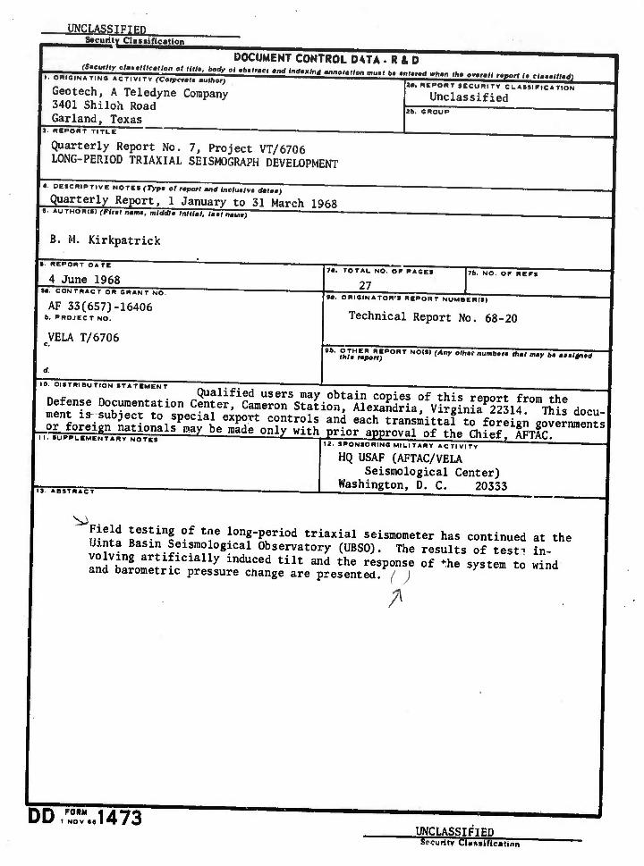
DOCUMENT CONTROL DATA R&D
ffi&i ^-"»"r " ""•■ g g "-"' g aaaa ggaBa aa ü ^a ^ a aga sag i m I. ORIGINATING ACTIVITY fCorpcr«!. «u/horl
Geotech, A Teledyne Company 3401 Shiloh Road Garland. Texas
3. BEPORT TITLI ~~~'~~~~~
2«. REPORT SECUniTY CLASSIFICATION
Unclassified 26. GROUP
Quarterly Report No. 7, Project VT/6706 LONG-PERIOD TRIAXIAL SEISMOGRAPH DEVELOPMENT
4. DESCRIPTIVE NOTCS (Typ0 olrmpotl mnd /ne/u.lv. dmlm,) "
Quarterly Report, 1 January to 31 March 1968 »• AUTHORIS) (Flnl nan», mlddla Inillml, ISmtSSSS) '
B. M. Kirkpatrick
e. REPORT DATE
4 June 1968 •«. CONTRACT OR GRANT NO.
AF 33(657)-16406 6, PROJECT NO.
VELA T/6706
d.
7a. TOTAL NO. OF PAGES
27 76. NO. OF REFS
M. ORIGINATOR'S REPORT NUMBCR(S|
Technical Report No. 68-20
,",■ S7.H«Jo?,;PORT NO,,, <Äny '"h" "'"""" *" ""^ *• "•'*>•"
10. DISTRIBUTION STATEMENT
Defense Documentation cS^f^TsK docu
^"Lr!;511^^- Üt,pWiai eXp0rt Controls *** each transmittal ?o foreig; Jv^mU _or foreign nataonals may be made only with prior anproval of the Chief^MT'8
12. SPONSORING MILITARY ACTIVITY
13. ABSTRACT
HQ USAF (AFTAC/VELA Seismological Center)
Washington, D. C. 20333
fnUf R6
inf ■ tf lon8-Period triaxial seismometer has continued at the Uinta Basin Seismological Observatory (UBS0). The results of test^ in-
ZdilLtlll^117 indUCed tilt and the resPonse of ^ «X^em to lind and barometric pressure change are presented, f )
DD FORM 1473 UNCLASSIFIED Security CUftsirication
— 'i ^ i
■ ■—■■■■■ - ■

wämm cation
KEY WORDS
Long-period borehole seismometer VT/6706
LftHK ■
J UNCLASSIFIED
Security Claatification
^—; n
"" ' . ' ~. '"!. ' i