best battery practices for frc teams - · pdf filebest battery practices for frc teams the...
TRANSCRIPT

Best Battery Practices
For FRC Teams
<R34> The only legal source of electrical energy for the ROBOT/HOSTBOT during
the competition is one MK ES17-12 12VDC non-spillable lead acid battery, OR one
EnerSys NP 18-12 battery, as provided in the 2011 KOP.

Current

Voltage
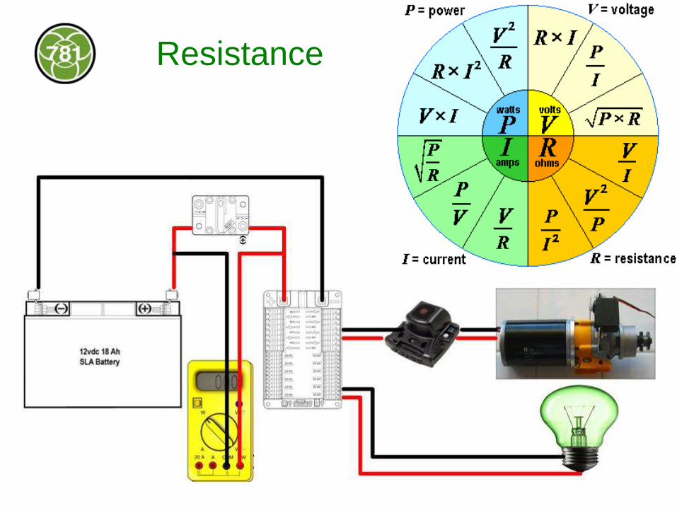
Resistance

VRLA Batteries
• Valve Regulated
(sealed)
• Lead Acid
• Deep cycle
motive battery
• 10 A typical
discharge

Chemistry
Volts2.1
O2H2PbSO2HSO2HPbOPb
overall
O2HPbSO2e3HHSOPBO
cathode
2eHPbSOHSOPb
anode
SO2HSOH
eelectrolyt
2442
2442
44
442

Inside the Battery
Discharge in any position, charge UPRIGHT

PbO2 Cathode, Pb Anode

Matted Glass Fiber Separators

Valves

Each Battery is Unique

Know your batteries!
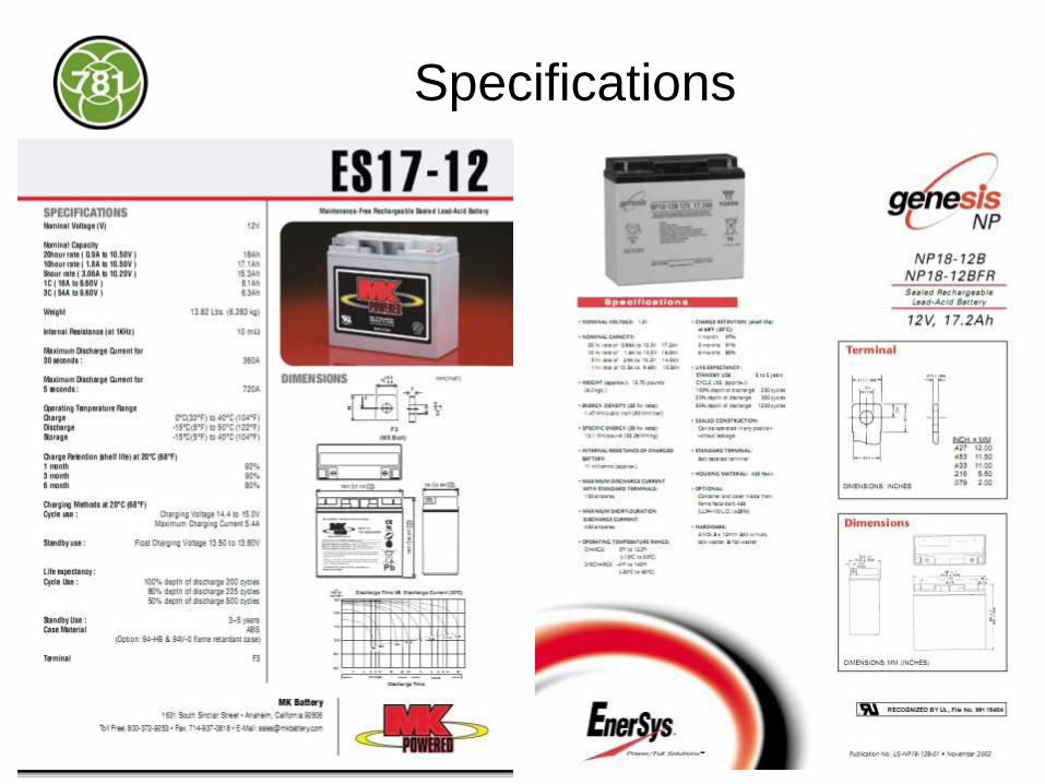
Specifications

Nominal Capacity
Genesis NP18-12B
• Q = 17.2 A-hr
• 20 hour rate
• i = 0.86 A to 10.5V
MK ES17-12
• Q = 18 A-hr
• 20 hour rate
• i = 0.9 A to 10.5V
Q = i (Amps) x Time (hours)

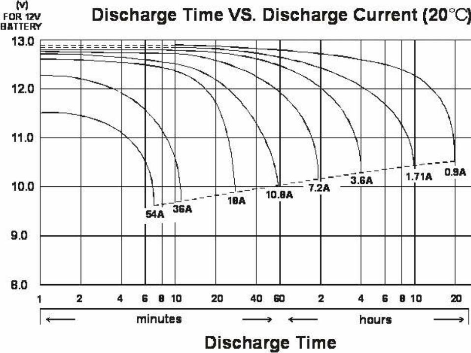
Capacity is not linear

How many Amps does the robot use?

Estimate current > Calculate time
Load Minimum (A) Maximum (A) Estimate (A)
2 each CIM motors 2 x 2.7 2 x 40 2 x10 = 20
compressor 0 10 2
arm motor 0.82 108.7 20
signal light 1.1 2.2 2
radio 1.0 2.5A 2.5
TOTAL 8.2 203.9 46
Nominal Capacity @ 46A ~ 6.3 Ahr (MK Battery)
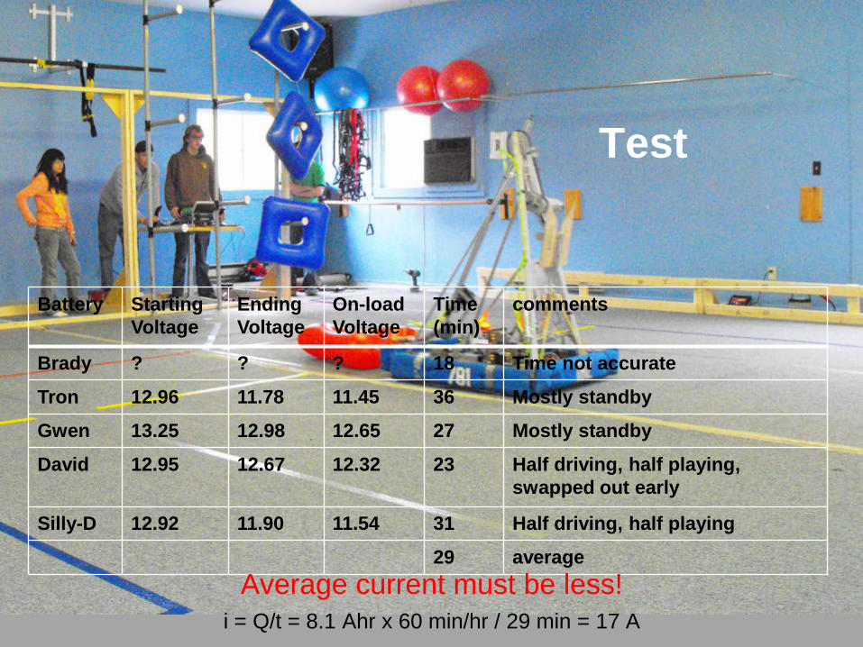
Test
Battery Starting
Voltage
Ending
Voltage
On-load
Voltage
Time
(min)
comments
Brady ? ? ? 18 Time not accurate
Tron 12.96 11.78 11.45 36 Mostly standby
Gwen 13.25 12.98 12.65 27 Mostly standby
David 12.95 12.67 12.32 23 Half driving, half playing,
swapped out early
Silly-D 12.92 11.90 11.54 31 Half driving, half playing
29 average
Average current must be less!
i = Q/t = 8.1 Ahr x 60 min/hr / 29 min = 17 A

Time per match?

How much Q is used in a match?
Battery capacity required for a match?
Qmatch = Qplaying + Qwaiting
= (2.25 min * 17 A) + (4.55 * 8 A) = 74.65 A-min
How many matches is a battery good for?
matches = Q / Qmatch
= 8.1 Ahr x 60min/hr x 486 A-min / 74.65 A-min
= 6 matches

How many batteries do we need?
IF no batteries are recharged, how many batteries
are required?
• 18 matches / 6 matches/battery = 3 batteries
Not confident – Add a Safety Factor!
3 batteries x 2 = 6 batteries

How long will a battery stay charged?

Cold Battery Capacity?
Store > -15C

How long to warm up a cold battery?
Store > -15C

Open Circuit Voltage Does NOT
Indicate State of Charge
10
11
12
13
14
0 20 40 60 80 100
OP
EN
CIR
CU
IT V
OL
TA
GE
(V
)
REMAINING CAPACITY (%)
OPEN CIRCUIT VOLTAGE VS REMAINING CAPACITY

Driver Station On-Load Voltage
<R61> A National Instruments 9201 module must be installed in slot 1 of the cRIO-FRC.
An analog breakout must be connected to this module. A jumper must be installed in the
“Power” position (two outer pins) on the analog breakout. The analog breakout must be
powered from the PD Panel. These connections enable monitoring of the battery charge
by the team and the Field Management System. This is a required element of the
ROBOT configuration.

Chargers
<R41> An automatic battery charger rated for a maximum of 6 amperes must be
used to charge the supplied batteries. When recharging the KOP batteries, either
the charger provided by FIRST or an automatic charger with an equivalent
charging current rating may be used.

Charging
Genesis NP18-12B
• 14.4 to 15.0 V
• 4.3 A maximum
MK ES17-12
• 14.4 to 15.0 V
• 5.4 A maximum

Chargers charge differently!
• Constant voltage (older)
• Constant current (newer)
• Combination (“smart”)
Read the manual!

Constant Current
• 2, 4 or 6 Amps
i = 4 Amps
Q = 17.1 Ahrs
Q = i * t
t = Q / i
= 17.1 / 4
= 4.275 hours

Constant Voltage
• 14.3 V
• Up to 6 A
Q = 17.1 Ahrs
Q = i * t
t = Q / i
= 17.1 / 6
= 2.85 hours
NOT!


“Smart” Chargers
• Desulphation < 0.5 hours
• Constant current 3.3 A
Q = 17.1 Ahrs
Q = i * t
t = Q / i
= 17.1 / 3.3
= 5.2 hours
• Constant voltage 14.4 A
= ? Hours
= observed < 2 hours
• TOTAL = 8 hours

Can we shorten the time
by charging 2 batteries in parallel?
No!
Need to charge twice the capacity:
2 x Q = 2 x 17.2 A-hr = 34.2 A-hr
Charge at a constant current
t = Q / A
t = 34.2 A-hr / 4.0 A = 8.5 hours
WARNING
If the batteries are not identical,
the battery currents will not be the same

Internal Resistance Changes with Age
Genesis NP18-12B
10 mΩ
MK ES17-12
11 mΩ
Team 781 observes 3mΩ (new) to 7mΩ (old)

Good Battery Charged too long
t = Q / i
Battery G
i1 = 2.8 A
t = 17.1 / 2.8 = 6.1 hr
Battery A
i2 = 1.2 A
t = 17.1 / 1.2 = 14.3 hr
Unequal current when charging
new and aged batteries in parallel

DON’T DO IT!

Make a Plan – Work the Plan • Sequence of using your batteries
• Number of matches per battery
• Sufficient time to charge
• Method of tracking battery state of charge

Mechanical Safety
• Lift with knees
• Hold close to your body
• Minimize grip lifts
• Don’t drop it!

<R16> When positioned on the ROBOT, the primary battery must be secured so that
it will not dislodge should the ROBOT be turned over or placed in any arbitrary
orientation.
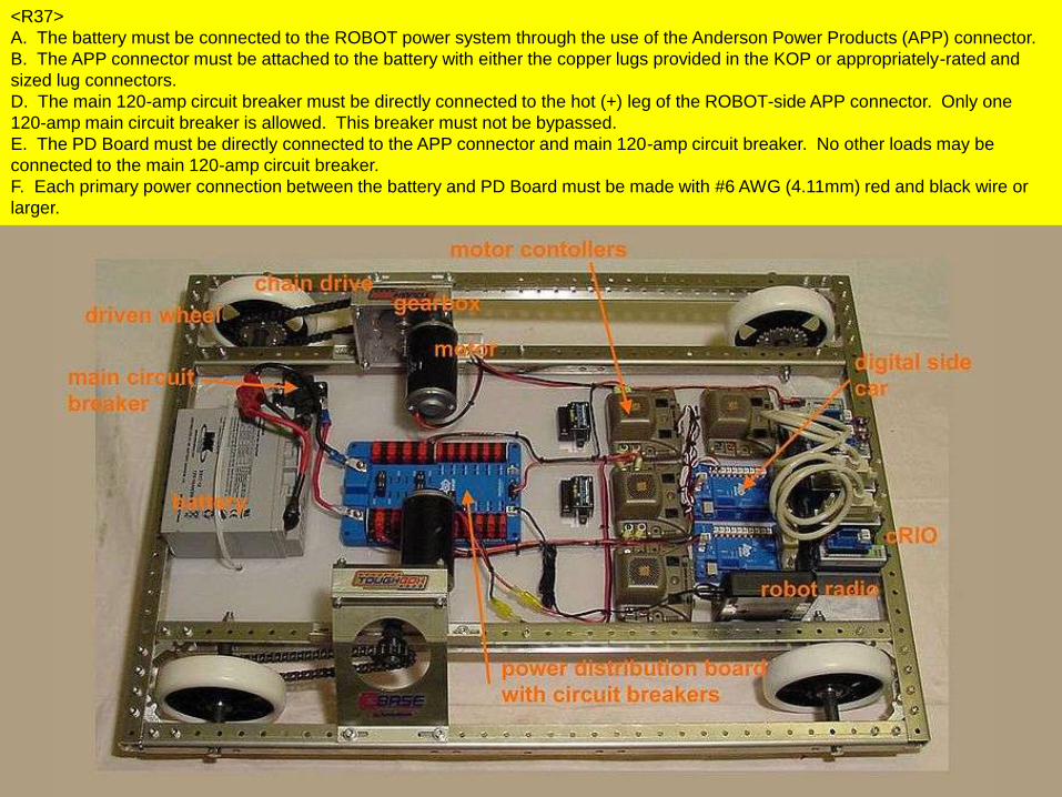
<R37>
G. The 120-amp circuit breaker must be quickly accessible from the exterior of the
ROBOT.

Electrical Safety
• Never short the terminals
• Insulate the terminals
• Install the Anderson
connectors and use the
battery plugs
• Use the 120 A circuit
breaker
• Inspect
– Before charging
– Before discharging


<R37>
C. The battery terminals and the connecting lugs must be insulated with shrink
tubing and/or electrical tape.


<R37>
A. The battery must be connected to the ROBOT power system through the use of the Anderson Power Products (APP)
connector.
B. The APP connector must be attached to the battery with either the copper lugs provided in the KOP or appropriately-rated
and sized lug connectors.
D. The main 120-amp circuit breaker must be directly connected to the hot (+) leg of the ROBOT-side APP connector. Only
one 120-amp main circuit breaker is allowed. This breaker must not be bypassed.
E. The PD Board must be directly connected to the APP connector and main 120-amp circuit breaker. No other loads may be
connected to the main 120-amp circuit breaker.
F. Each primary power connection between the battery and PD Board must be made with #6 AWG (4.11mm) red and black
wire or larger.
<R37>
A. The battery must be connected to the ROBOT power system through the use of the Anderson Power Products (APP) connector.
B. The APP connector must be attached to the battery with either the copper lugs provided in the KOP or appropriately-rated and
sized lug connectors.
D. The main 120-amp circuit breaker must be directly connected to the hot (+) leg of the ROBOT-side APP connector. Only one
120-amp main circuit breaker is allowed. This breaker must not be bypassed.
E. The PD Board must be directly connected to the APP connector and main 120-amp circuit breaker. No other loads may be
connected to the main 120-amp circuit breaker.
F. Each primary power connection between the battery and PD Board must be made with #6 AWG (4.11mm) red and black wire or
larger.

Chemical Safety

Be Prepared

How do you know your battery is sick?
• Charger indicates it’s sulphated.
• Charger indicates it’s charged too soon.
• Charger takes a long time to charge.
• The case is distorted.
• The battery is unusually hot.
• The open-circuit voltage is unusually low or
high.
• The on-load voltage is unusually low.

- High self-discharge
- Wouldn’t charge 2A
- Too fast charge 4A

Distortion, Heat Damage
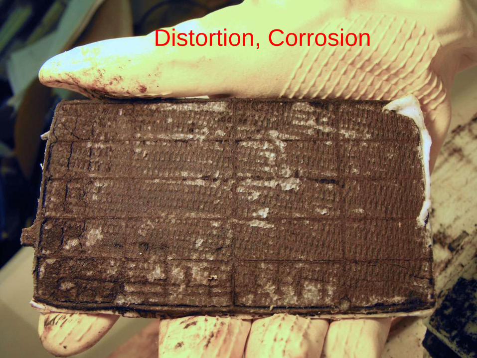
Distortion, Corrosion

Sulphated Plates

More Sulphate
MICHELLE’S RULE
Recharge your batteries as soon as possible after use.

When will your battery die?
Genesis NP18-12B
100% discharge 250 cycles
50% 550 cycles
30% 1200 cycles
3 to 5 years
MK ES17-12
100% discharge 200 cycles
80% 225 cycles
50% 500 cycles
3 to 5 years

Disposal
• Hazardous Waste Day
– Only twice a year; plan for it
– Volunteer

Best Battery Practices
• Follow the rules
• Assign someone to know the batteries
• Keep a battery log
• Don’t leave batteries in a discharged state
• Don’t charge batteries in parallel
• Develop a plan to use/charge batteries at
competition
• Don’t keep sick batteries; dispose of them properly