best practice guide installation of suspended ceilings · • standard method of measurement 7th...
TRANSCRIPT
BEST PRACTICE GUIDE INSTALLATION OF SUSPENDED CEILINGS
www.thefis.org
2
First edition published January 2012
This edition published April 2015
ISBN 978-0-9565341-2-5
World copyright reserved
Copyright © 2015 FIS
Published by FIS
No part of this document may be reproduced or
transmitted in any form or by any means electronic,
chemical or mechanical, including photocopying, any
information storage or retrieval system without licence or
other permission in writing from the copyright owner.
While every care has been taken to ensure the accuracy
of the details presented in this document, we regret that
FIS cannot be held responsible for any errors or
omissions contained herein.
Supported by
This project has been delivered with support from the CITB
Growth Fund, which aims to ensure that the construction
industry has the right people, with the right skills, in the right
place, at the right time and is equipped to meet the future
skills demands of the industry.
BEST PRACTICE GUIDE INSTALLATION OF SUSPENDED CEILINGS
3
1 Foreword . . . . . . . . . . . . . . . . . . . . . . . . . . . . . . . . . 4
2 Introduction . . . . . . . . . . . . . . . . . . . . . . . . . . . . . . . . . 5
2.1 Scope . . . . . . . . . . . . . . . . . . . . . . . . . . . . . . . . . . . . . . . . . . . . . 5
3 Recommendations for tendering
and measurement . . . . . . . . . . . . . . . . . . . . . . . . . . . . . 6
3.1 Contract conditions . . . . . . . . . . . . . . . . . . . . . . . . . . . . . . . . . . . . 6
3.1.1 Basis of measurement . . . . . . . . . . . . . . . . . . . . . . . . . . . 6
3.1.2 Programme . . . . . . . . . . . . . . . . . . . . . . . . . . . . . . . . . . . . 6
3.2 Main contractor (attendances) . . . . . . . . . . . . . . . . . . . . . . . . . . . . 6
3.2.1 General scaffolding . . . . . . . . . . . . . . . . . . . . . . . . . . . . . 6
3.2.2 Specialist scaffolding . . . . . . . . . . . . . . . . . . . . . . . . . . . . 6
3.2.3 Unloading . . . . . . . . . . . . . . . . . . . . . . . . . . . . . . . . . . . . . 6
3.2.4 On site storage . . . . . . . . . . . . . . . . . . . . . . . . . . . . . . . . 7
3.2.5 Temporary lighting and power . . . . . . . . . . . . . . . . . . . . . 7
3.2.6 Working space . . . . . . . . . . . . . . . . . . . . . . . . . . . . . . . . . 7
3.2.7 Waste management . . . . . . . . . . . . . . . . . . . . . . . . . . . . . 7
3.3 Design requirements. . . . . . . . . . . . . . . . . . . . . . . . . . . . . . . . . . . . 7
3.3.1 Drawings for tender enquiry . . . . . . . . . . . . . . . . . . . . . . 7
3.3.2 Specification . . . . . . . . . . . . . . . . . . . . . . . . . . . . . . . . . . 8
3.4 Building owner inviting tender . . . . . . . . . . . . . . . . . . . . . . . . . . . . 8
4 Contract planning . . . . . . . . . . . . . . . . . . . . . . . . . . . . . 9
4.1 Integration of ceiling related services . . . . . . . . . . . . . . . . . . . . . . 9
4.2 Sequence of installation . . . . . . . . . . . . . . . . . . . . . . . . . . . . . . . . . 9
4.3 Materials management . . . . . . . . . . . . . . . . . . . . . . . . . . . . . . . . . 10
4.4 Site conditions . . . . . . . . . . . . . . . . . . . . . . . . . . . . . . . . . . . . . . . 10
4.5 Setting-out points . . . . . . . . . . . . . . . . . . . . . . . . . . . . . . . . . . . . 10
4.6 Programme . . . . . . . . . . . . . . . . . . . . . . . . . . . . . . . . . . . . . . . . . . 10
5 Setting-out the ceiling . . . . . . . . . . . . . . . . . . . . . . . . 11
5.1 Setting-out and levelling . . . . . . . . . . . . . . . . . . . . . . . . . . . . . . . 11
5.2 Tolerances of suspended ceilings . . . . . . . . . . . . . . . . . . . . . . . . 11
5.3 Top fixings . . . . . . . . . . . . . . . . . . . . . . . . . . . . . . . . . . . . . . . . . . 11
5.4 Hangers 12
5.5 Installing a ceiling beneath an existing ceiling . . . . . . . . . . . . . . 13
5.6 Ceiling mounted light fittings / downlighters . . . . . . . . . . . . . . . 13
5.7 Appearance . . . . . . . . . . . . . . . . . . . . . . . . . . . . . . . . . . . . . . . . . 14
6 Suspended ceiling system types
and installation procedures . . . . . . . . . . . . . . . . . . . . . 15
6.1 Exposed grid systems . . . . . . . . . . . . . . . . . . . . . . . . . . . . . . . . . 15
6.2 Concealed grid systems . . . . . . . . . . . . . . . . . . . . . . . . . . . . . . . . 17
6.3 Acoustic infills for use in metal ceilings . . . . . . . . . . . . . . . . . . . 19
6.4 Stretch / tensioned ceilings . . . . . . . . . . . . . . . . . . . . . . . . . . . . . 19
6.5 Linear strip / screen ceilings . . . . . . . . . . . . . . . . . . . . . . . . . . . . 20
6.6 Raft / island ceilings . . . . . . . . . . . . . . . . . . . . . . . . . . . . . . . . . . . 20
6.6.1 Fixed sized, pre-made rafts . . . . . . . . . . . . . . . . . . . . . . 20
6.6.2 Site constructed rafts . . . . . . . . . . . . . . . . . . . . . . . . . . 21
6.7 Acoustic baffle ceilings . . . . . . . . . . . . . . . . . . . . . . . . . . . . . . . . 21
6.8 Access panels . . . . . . . . . . . . . . . . . . . . . . . . . . . . . . . . . . . . . . . . 22
6.9 Perimeter and transition trims . . . . . . . . . . . . . . . . . . . . . . . . . . . 22
7 Suspended ceilings and fire . . . . . . . . . . . . . . . . . . . . 23
7.1 Structural fire resistance . . . . . . . . . . . . . . . . . . . . . . . . . . . . . . . 23
7.1.1 Integrity of the grid assembly . . . . . . . . . . . . . . . . . . . . 23
7.1.2 Hold down clips . . . . . . . . . . . . . . . . . . . . . . . . . . . . . . . 23
7.1.3 Continuity of fire resistance . . . . . . . . . . . . . . . . . . . . . 23
7.2 Cavity barriers . . . . . . . . . . . . . . . . . . . . . . . . . . . . . . . . . . . . . . . 24
8 Contracting support administration . . . . . . . . . . . . . . 25
8.1 Sustainability . . . . . . . . . . . . . . . . . . . . . . . . . . . . . . . . . . . . . . . . 25
8.2 Health and safety . . . . . . . . . . . . . . . . . . . . . . . . . . . . . . . . . . . . . 25
8.3 Operation and maintenance manuals . . . . . . . . . . . . . . . . . . . . . . 25
9 Glossary . . . . . . . . . . . . . . . . . . . . . . . . . . . . . . . . . . . 26
10 Acknowledgements . . . . . . . . . . . . . . . . . . . . . . . . . . . 27
CONTENTS
4
This guide has been developed by FIS to promote best practice
in the installation of suspended ceilings.
There are very few commercial building projects, new build
or refurbishment, which do not have suspended ceilings as
one of their key construction components. Usually
representing the largest uninterrupted surface, they make a
major contribution to the overall appearance and acoustic
quality of the finished space.
As a platform for lighting fixtures, HVAC diffusers, sound
systems and wireless antenna panels, suspended ceilings
deliver functionality to the building owner. For the
construction team they offer a rapidly installed, dry and
relatively clean process.
However, for the completed ceiling to meet the legitimate
expectations of the building owner, occupier, design
professionals and construction team, the selection and
installation process must be carefully considered and
understood by all parties.
Suspended ceilings are a finishing trade and require
installation by specialist contractors. The specialist
contractor will provide the high levels of management,
operative skills and resources, essential to deliver a high
quality product. Their considerable experience on similar
projects will be of significant assistance to the
construction team.
System manufacturers design and produce engineered
ceiling systems, which are then tested to meet the
requirements for various environmental and performance
levels. The provision of a whole range of design solutions is
part of the responsibilities taken by manufacturers, who have
a key role to play in ceiling design.
FIS has grown over the past 50 years to become the
leading trade association for the interiors fit out sector
of the construction industry, representing companies
involved in the manufacture, supply and installation of all
aspects of interior fit out and refurbishment. Its members
can provide optimum solutions of the installation of
interior elements.
This FIS Best Practice Guide for the Installation of
Suspended Ceilings is not intended as a definitive technical
manual, as the manufacturers’ recommendations must
always be followed, but as a guide to the construction
team as to best practice. FIS encourages all its members
to follow the principles set out in this guide.
FOREWORD 1
5
A satisfactory suspended ceiling installation must fulfil three
main requirements:
• Appearance
• Function (performance)
• Structural stability.
These can only be achieved when the ceiling is installed
under proper site conditions (see ‘FIS Site Guide for
Suspended Ceilings’), using the correct techniques, the right
materials for the job, a high standard of workmanship and at
all times adhering to health and safety regulations.
It should be noted that under no circumstances can the
back of a suspended ceiling be considered a walkway or to
accommodate cables ducts and trunking, which should be
housed in appropriate trays, independently supported from
the soffit. If a walkway in the ceiling void is required
separate provision must be made.
2.1 SCOPE
This best practice guide covers the installation of all forms
of suspended ceiling.
While the practices described apply equally to ceilings
which are intended to provide structural fire resistance,
additional requirements may have been imposed to obtain
the fire endurance classification of a particular floor-ceiling
construction. Such details should be obtained from the
manufacturer and approved by the client / professional team
before the ceiling installation begins.
Additional measures may be necessary to meet sound
attenuation requirements when ceiling voids extend over
adjacent rooms. This may involve the installation of sound
attenuating barriers in the ceiling void or modification of the
ceiling panels. The advice of the manufacturer of the
acoustic materials should be sought, together with reference
to the FIS publication ‘A Guide to Office Acoustics’. In some
cases the services of an acoustician may be required.
INTRODUCTION 2
6
To enable the specialist contractor to submit a realistic
tender it should be informed of the items given below.
Tenders should normally be submitted on the basis that
the work is to be carried out continuously; hangers, grids
and panels being fixed in one operation and the work
completed during one visit to site. Should more than
one visit be anticipated the tenderers should be
informed accordingly.
3.1 CONTRACT CONDITIONS
The form of contract, for example JCT, NEC, or bespoke
form, should be stated and the relevant sections of those
contracts completed (contract particulars / contract data),
which will include the following particulars:
• Payments (ideally a list of due dates and final dates
for payment)
• Retention (usually 3-5%)
• Discounts (it is preferable to have contracts placed on a
nett of discount basis)
• Insurances
• Liquidated and ascertained damages
• Defects liability period (now called rectification period
under JCT11)
• Programme (period and likely commencement date)
• Ascertainment of prices for variations
• Basis of day work charges
• Responsibility for design
• Requirements for bonds, warranties and parent
company guarantees
• Waste management.
3.1.1 Basis of measurementThe basis of measurement may take one of the
following forms:
• Standard Method of Measurement 7th edition (SMM7)
• New Rules of Measurement (NRM)
• Quantities taken off drawings by the specialist contractor
and expressed as a lump sum (plan and spec) or an
inclusive price per square metre
• Site survey by specialist contractor.
3.1.2 ProgrammeIn addition to the information given in 3.1, as much
information as is available should be given to the tenderer
regarding the main contractors building programme. If the
main contractor has been appointed, ideally the ceiling
tenderer should be given the dates of the work together
with details of sequencing.
3.2 MAIN CONTRACTOR (ATTENDANCES)
Attendances together with services and facilities should
be clearly defined before entering into final contract
agreement. Both main contractor and specialist contractor
should clarify in writing what they have allowed for.
Good practice would be to agree a schedule, provided by
either party, on what each is providing so that the situation
is clear.
3.2.1 General scaffoldingGeneral scaffolding is normally the responsibility of the main
contractor. Unless otherwise stated, general scaffolding
means all scaffolding to the exterior of the building
together with any scaffolding that the main contractor
requires for his own use within the building. Reasonable
and free use of general scaffolding and hoisting tackle
already erected by the main contractor should be allowed to
the specialist contractor, but general scaffolding is usually
not suitable for the needs of the ceiling specialist and
specialist scaffolding should be provided.
3.2.2 Specialist scaffoldingWhen the provision of specialist scaffolding is the
responsibility of the main contractor, it should be provided,
erected and dismantled free of any charge and conform to
current regulations and should be erected to the specialist
contractors requirements within the agreed programme and
in advance of the specialist contractor’s work. It should not
be dismantled before satisfactory completion of the work.
If special scaffolding is the responsibility of the
specialist contractor, it is assumed that the cost is included
as a separate item in the tender. The main contractor
should provide sufficient space for free movement of
scaffolding and a suitable floor surface to properly support
the scaffolding.
3.2.3 UnloadingUnloading the specialist contractor's material and plant and
distributing safely to the exact work locations should be
defined as either being the responsibility of the main
contractor or the specialist contractor. The former to be at
the cost of the main contractor, and if the latter, the cost is
deemed to be included in the specialist contractor’s tender.
RECOMMENDATIONS FOR TENDERING AND MEASUREMENT 3
7
3.2.4 On site storageWhen storage of specialist contractor's material, plant, etc
is the responsibility of the main contractor, free use of a
suitable secure, dry covered area of sufficient size for
stacking on a flat base should be provided (see also 4.3).
In the case of the specialist contractor being responsible for
storage, the cost should be included in its tender.
3.2.5 Temporary lighting and powerThe responsibility for the provision of suitable lighting and
suitable power supply should be stated. These must be in
accordance with current safety regulations. Lighting levels
should be designed to allow the installation of the ceiling to be
completed to the level of quality expected, particularly
relevant for any ceilings where the surface will receive a finish.
3.2.6 Working spaceSufficient space should be provided free from traffic and
interruption for the specialist contractor to carry out the
assembly of hangers, grid components and panel cutting at
floor level as part of the normal process of the work.
3.2.7 Waste managementThe responsibility for clearing and removing waste material
should be clearly defined pre-tender. During the suspended
ceiling installation process, there can generally be the following
types of waste removal:
a The main contractor providing waste segregation
skips / bins for items such as plasterboard, mineral wool,
rock / glass wool, wood, aluminium or metal, and the
specialist contractor placing waste material in the relevant
skip / bin. The main contractor then takes responsibility
for removal from site to a local recycling centre.
b The specialist contractor is asked to take responsibility to
remove segregated waste, as detailed above to the
recycling centre. To do this a ‘waste carrier licence’ is
required. Without one a suitable authorised company will
need to be appointed to collect the waste and transport
to the local recycling centre.
c Recycling existing ceiling material or off cuts back to the
manufacturer for recycling in the manufacturing process.
This would generally be volume related, and specified by
the manufacturer of the material on a minimum quantity
basis. In such cases, the removed material would generally
be placed on pallets, or bags which would then be
collected either by the manufacturer or a waste removal
company and returned to the manufacturer’s plant for
recycling into the manufacturing process.
Clearly, if manufacturers are not in the UK, then this
method is not either cost effective or eco-friendly. At
present, WRAP is working with industry to establish a
more robust recycling system for all types of ceiling
material.
3.3 DESIGN REQUIREMENTS
Whilst in many cases the design and product selection is
carried out by the specifier to the clients’ requirements,
design input is being increasingly sought from the main
contractor the specialist contractor and the manufacturer.
So in the very early stages clarification of any design input
required is needed by all parties and confirmed in writing.
3.3.1 Drawings for tender enquirya Location drawings should be provided indicating the
various areas covered by the enquiry, cross-referenced to
perimeter and other details and, if required, illustrating
changes in level and junctions between dissimilar
materials. Minimum scale 1:200 should only be used if
reflected ceiling plans (RCP) referred to in 3.3.1(b) are
to a scale not less than 1:100.
b Where layout of ceiling panels is important, reflected
ceiling plans should be included showing setting out points
for the ceiling preferably to a scale 1:100 (minimum).
c Where recessed light fittings, grilles are to be used, these
should be indicated on the drawings referred to in 3.3.1(b),
together with all necessary support details including, but
not limited to, the weight and manufacturers reference.
Where the specialist contractor is not responsible for
design, then full design details must be provided.
d The following information should be included:
• Detail drawings to support design and installation
• Level of suspended ceiling above finished floor level
• Level of structural soffit above ceiling void or depth of
suspension together with nature of soffit for top fixing of
ceiling hangers
• Lines of projection into ceiling void, eg downstand beams
together with an indication of their size
• Any other obstructions within the ceiling void eg
ventilation ducts etc
• Details of removable panels for access to services,
controls etc, possibly given provisionally, together with
those areas in which complete demountability is required
for unobstructed access to services
RECOMMENDATIONS FOR TENDERING AND MEASUREMENT 3
8
• Rooflights, blind boxes, bulkheads, upstands and
plasterboard margins
• Siting of sprinklers, fire detectors, access to fire
dampers, air distribution outlets or other terminal
equipment
• Position of partition head members
• Position and nature of cavity barriers
• Gradient of floor
• Specification of top fixing anchor.
3.3.2 SpecificationThe specification should state basic design criteria
under the headings given below, together with outline
selection of panels, supporting grid components and
design loading. This is particularly important where the
superimposed load of light fittings and other ceiling
integrated or mounted equipment could affect the
visual appearance and performance of the ceiling. It
should be considered that the ceiling manufacturer is
involved in assisting writing detailed specifications
where appropriate.
If the design is not in general accordance with the
recommendations of this guide, an official proving test may be
required. In such circumstances, the designer (or specifier)
should at an early stage contact the specialist contractor for
recommendations and advice regarding costs of any necessary
test and any work in conjunction therewith.
Design criteria should be given under the following headings
(where applicable):
• System type
• Module size and thickness
• Perimeter / transition trim detail
• Degree of thermal insulation
• Sound absorption
• Sound attenuation
• Humidity resistance
• Required fire resistance
• Light reflectance level.
3.4 BUILDING OWNER INVITING TENDER
When the owner of an existing building is inviting tenders the
following information should be given in addition to
specification and design details:
• Location of site and access
• New building, existing building or extension
• Availability of lifts and stairs in existing buildings and use
of power and hoists for bringing materials and plant into
the building
• Function of building
• Main contractor’s programme and building owner’s
stipulation affecting the sequence and working hours of
the works
• Limitations imposed by occupancy on construction work.
RECOMMENDATIONS FOR TENDERING AND MEASUREMENT 3
9
Crucial to the success of a ceiling installation is the planning
and co-ordination which precedes the work. The aim of this
planning should be to establish:
EXACTLY WHAT IS TO BE DONE
HOW IT IS TO BE DONE
WHEN IT IS TO BE DONE
METHOD
SPECIFICATION
PROGRAMME
These steps are inter-related and it is preferable not to
discuss them separately. However, their identification will
assist a methodical approach to contract planning.
All three items should have been clearly stated before
tendering and indeed should have formed the basis of the
tender. However, after entering into a contract it is necessary
for the specialist contractor to confirm specification, method
of working and programme.
The first action by the specialist contractor must be to
establish the date by which materials must be ordered to meet
programme requirements. This will set a limit to the time
available for receipt of contract drawings, the production of
specialist working drawings (if these are required) and
checking and approval by the client. Where special sizes,
sections, materials or finishes are involved this ‘lead time’ can
be considerable. It is often underestimated with serious
consequences if contracts are delayed, leading to claims
against the specialist contractor.
Next the detailed programme of work must be agreed with
the main contractor. This will include start and completion dates
for the subcontract work or specific phases of the work and will
be closely related to the activity of other trades whose work
can be expected to interact with the suspended ceiling.
A period of notice should be agreed for confirming or
amending delivery dates.
The specifier should issue contract drawings which
clearly detail the specification required and all ceiling
related services. These drawings should include a fully
co-ordinated reflected ceiling plan (RCP) that detail all
interfaces with mechanical, electrical and related
components that relate to the suspended ceiling
membrane. This is to allow all services and penetrations
to be shown, detailed and overlaid with the RCP. The
specialist contractor should check drawings on receipt to
ensure that requirements are fully understood.
Any queries must be raised with the specifier or
main contractor without delay and be prepared to produce
detail drawings if requested. Details which commonly require
such attention include fixing of hangers to the structure, the
junction of ceiling with perimeter walls, upstands, rooflight
linings and head fixing of demountable partitions.
4.1 INTEGRATION OF CEILING RELATED SERVICES
It is essential at this stage that areas of potential interaction
between the ceiling system and building
services are identified.
These usually include:
• Dimensional co-ordination of recessed luminaires and
other terminal equipment with the tile / panel module
• Additional support for light fittings, air distribution
outlets, etc
• When ceiling tiles / panels are to be partially supported
by light fittings or air terminal devices, that flanges
are adequate and correctly dimensioned and access
requirements are maintained
• Lateral stability of ceiling grid when interrupted by
electrical trunking, light fittings or other ceiling level
equipment
• Obstruction of hangers by heating and ventilating
ductwork
• Insufficient vertical space where ductwork, recessed
light fittings and / or ceiling suspension components
overlap
• Location of access panels for services and clarification
of headroom required for any upward opening
• Sprinkler heads coinciding with main support sections
of the ceiling system
• Clarification of any co-ordination, including colour,
required between ceiling grids and trims and any light
fitting or speaker trims.
4.2 SEQUENCE OF INSTALLATION
When the ceiling specification and integration with the building
services are established the sequence of
installation and the method of working should be
considered. It is necessary for all work above the ceiling
to be installed before the ceiling installation commences.
Where lighting trunking or light fittings are recessed
into the ceiling it maybe desirable for this equipment to
be installed by the specialist contractor. It may also be
necessary for the ceiling panels to be installed later to give
CONTRACT PLANNING 4
10
time for air distribution and electrical connections to be
made. If this sequence was not foreseen at the time of
tendering it may now be necessary to negotiate new or
revised rates with the specialist contractor. This only serves
to emphasise the desirability of appointing specialist
contractors as early as possible in the building process.
4.3 MATERIALS MANAGEMENT
For building construction to be efficient and economical the
management of materials must be efficient from the point
of specification to incorporation in the works. Orders must
be placed with suppliers or manufacturers to allow ample
time for manufacture or procurement. This is particularly
important with special components or special sizes when
relatively long lead times are likely.
Building programmes are commonly disrupted for a
variety of reasons eg bad weather, industrial disruption
affecting delivery of major components, changes of policy
by clients. It is important that suppliers are kept informed
of possible delays in the building programme which may
require delay in delivery to site. Materials delivered too
early to a site are likely to be damaged. Inadequate notice
of delay may invoke charges from suppliers particularly
if products ordered are being bespoke manufactured for
the project.
The specialist contractor must arrange with the main
contractor for the satisfactory receipt and storage of its
materials. All concerned must be made aware that ceiling
materials are generally fragile and require very careful handling
and storage (see also 3.2.4).
4.4 SITE CONDITIONS
It cannot be too strongly emphasised that suspended ceilings
are essentially a finishing trade and therefore the building
should be in a proper condition with regard to cleanliness,
humidity and temperature before suspended ceilings are
installed. The building should be fully enclosed, all wet work
completed and dried out.
In the case of wet felted mineral wool ceilings the buildings
should be suitably heated and ventilated. Temporary heating
or drying arrangements should be properly maintained and
closely monitored. Metal and certain stone wool and glass
wool products can be installed prior to the building being
completely sealed from the outside elements and do not
require buildings to be heated or on site acclimatised.
The manufacturer’s recommended site conditions for
the installation of its materials should be followed.
Suspended ceiling work is normally carried out in one
operation. The prior fixing of hangers or main grids as a
separate operation from the fixing of the panels will add
to the cost of the installation.
Where mobile platforms are used, areas required for
installation should be clean and clear of equipment and
materials of other trades to provide an adequate and safe
working space. The specialist contractor should leave these
areas in a clean state after installation of the ceiling.
4.5 SETTING-OUT POINTS
It is essential that the setting-out points common to all
trades are established early and clearly indicated on the
working drawings. It is also essential that all consultants,
service contractors etc work to the same setting-out grid lines
and datums and that these are established on the site by the
main contractor in each ceiling area. Setting-out lines should
be in both directions and squared accurately.
Designers should note that tolerances in factory made
ceiling units are less than those usually accepted in building
structures and it may therefore be impossible in large ceiling
areas to maintain a strict alignment with modular elements
such as structural columns or window mullions.
4.6 PROGRAMME
Realistic programming requires great care and depends on
the professionalism and integrity of the various parties
involved. In a building designed with a high concentration
of services the various trades involved rely heavily on
every member of the building team maintaining the correct
rate of progress.
This can sometimes lead to uneconomical rates of working
for some trades and consideration should be given to
rationalising the work so that the specialist contractor
installs equipment of other trades, for example, recessed
luminaires and air terminal devices. Such rationalisation has
the effect of disengaging the trades so that they rely less
on each other for smooth progress and ensures
co-ordination of the visible units in the ceiling.
CONTRACT PLANNING 4
11
There is a great variety of suspended ceilings and it is not
intended to describe in detail precisely how to install but
rather to deal with the items which are common to most
ceiling systems. The manufacturer’s recommendations for
installation should always be followed.
5.1 SETTING-OUT AND LEVELLING
It is essential that setting-out points and datums common to
all trades are provided at an early stage on the design
drawings and that these are marked, together with
elevation bench marks, in each ceiling area on the site by
the main contractor.
It is then imperative that all trades work from the same
setting-out points and datums.
The ceiling height in each ceiling area should be marked in
relation to the elevation bench marks and then transferred
around the area by means of water level or rotating laser
levelling device that has a current calibration certificate.
Setting-out lines must be squared accurately at the outset.
Care must be exercised to avoid ‘creep’ of tile units relative to
the building module. These points are particularly critical in
large ceiling areas (see 4.5).
It is important that other trades need to be made aware
of the minimum clearance required to get ceiling tiles in or
out on all systems.
5.2 TOLERANCES OF SUSPENDED CEILINGS
Industry has taken a view over the years that if the ceiling
looks flat and no deviation in level is visible from floor level it
has been installed to acceptable tolerance (see also 4.5).
BS EN 13964 : 2004, clause A.5.2 states: ‘The maximum
deviation from flatness should be less than or equal to 2mm
per metre length, with a maximum of 5mm over a 5m length,
measured horizontally at the location of the suspension in any
direction (linear interpolation is used to determine the
tolerance on shorter lengths). These requirements apply for
the installation of the substructure, the membrane components
and the edge profiles’.
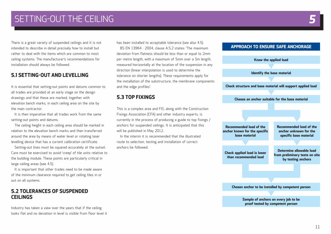
5.3 TOP FIXINGS
This is a complex area and FIS, along with the Construction
Fixings Association (CFA) and other industry experts, is
currently in the process of producing a guide to top fixings /
anchors for suspended ceilings. It is anticipated that this
will be published in May 2012.
In the interim it is recommended that the illustrated
route to selection, testing and installation of correct
anchors be followed.
APPROACH TO ENSURE SAFE ANCHORAGE
Identify the base material
Know the applied load
Check structure and base material will support applied load
Choose an anchor suitable for the base material
Chosen anchor to be installed by competent person
Sample of anchors on every job to be proof tested by competent person
Recommended load of the anchor known for the specific
base material
Check applied load is lower than recommended load
Recommended load of the anchor unknown for the
specific base material
Determine allowable load from preliminary tests on site
by testing anchors
SETTING-OUT THE CEILING 5
12
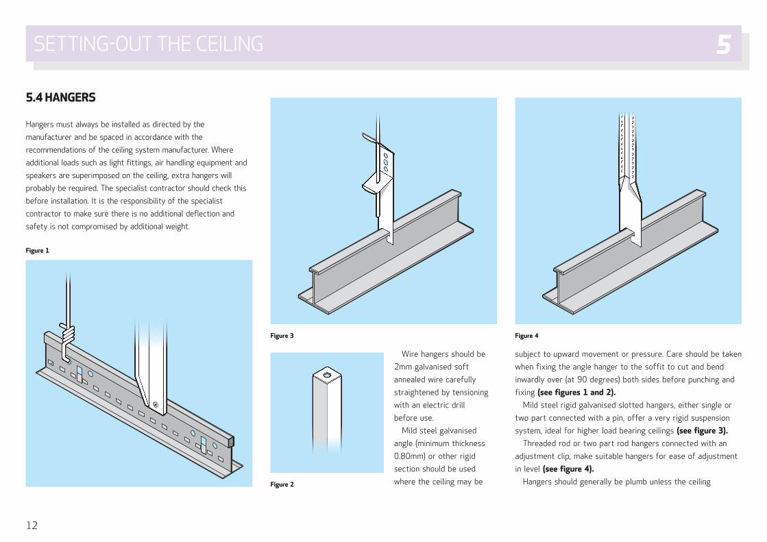
5.4 HANGERS
Hangers must always be installed as directed by the
manufacturer and be spaced in accordance with the
recommendations of the ceiling system manufacturer. Where
additional loads such as light fittings, air handling equipment and
speakers are superimposed on the ceiling, extra hangers will
probably be required. The specialist contractor should check this
before installation. It is the responsibility of the specialist
contractor to make sure there is no additional deflection and
safety is not compromised by additional weight.
Wire hangers should be
2mm galvanised soft
annealed wire carefully
straightened by tensioning
with an electric drill
before use.
Mild steel galvanised
angle (minimum thickness
0.80mm) or other rigid
section should be used
where the ceiling may be
subject to upward movement or pressure. Care should be taken
when fixing the angle hanger to the soffit to cut and bend
inwardly over (at 90 degrees) both sides before punching and
fixing (see figures 1 and 2).
Mild steel rigid galvanised slotted hangers, either single or
two part connected with a pin, offer a very rigid suspension
system, ideal for higher load bearing ceilings (see figure 3).
Threaded rod or two part rod hangers connected with an
adjustment clip, make suitable hangers for ease of adjustment
in level (see figure 4).
Hangers should generally be plumb unless the ceiling
Figure 1
Figure 2
Figure 3 Figure 4
SETTING-OUT THE CEILING 5
13
manufacturer or site conditions otherwise dictate and should
not press against insulation covering ducts, pipes or other
services. If hangers must be fixed diagonally to avoid
obstructions in the void, the horizontal force or lateral
movement should be offset by bracing with rigid hangers.
Connection of the hanger to the load bearing component of
the suspension system is critical and must be related to the
point loading especially where long spanning sections are used
or ceiling mounted equipment imposes additional loads.
There may be a requirement for a sub-grid to be installed
between the soffit and the ceiling level. This would generally
be to allow wider fixing centres to the soffit to avoid
equipment in the void. In such cases a consulting engineer
should be asked to determine the correct sections to use in
the process.
5.5 INSTALLING A CEILING BENEATH AN EXISTING CEILING
It is not best practice to install a new suspended ceiling from
an existing suspended ceiling and as such should
be avoided.
On no account should ceilings be installed using existing
inverted tee exposed grid systems as a primary grid for a
new ceiling.
Installing an acoustic ceiling below a mass barrier such as
an MF ceiling, which is common practice in cinemas, should
only be undertaken if the primary anchors and MF ceiling
have been designed to accept the additional load of the
ceiling, including any lighting or ancillary M & E equipment.
Care must be taken not to compromise the integrity or
performance of the mass barrier. Manufacturers
recommendations should be taken at all times.
On new installations of double membrane ceilings it is
strongly recommended that both ceilings are installed by
the same specialist contractor. Where possible separate
top fixings and hangers for the secondary ceiling should
be installed before closing up the primary ceiling. Even
when both suspended ceilings are new, evaluation of both
ceiling systems, top and bottom fixings, fastening to grids
and weight loadings must be carried out prior to carrying out
any work.
Reuse of existing anchorsIt is not best practice to use existing top fixings / anchors
without proper proof testing. Evaluations must be carried
out by a competent person.
5.6 CEILING MOUNTED LIGHT FITTINGS /DOWNLIGHTERS
Light fittings should be installed in any type of suspended
ceiling in a manner which will not compromise the ceiling
performance. Cables to fittings must not be laid directly
on the back of the suspended ceiling as this could cause
damage to the cables or pose unacceptable increased
weight to the ceiling. Cables should therefore always be
independently supported by use of cable trays, conduit or
trunking. (NICEIC Technical Manual C49-13 refers).
Light fittings must not be supported from the ceiling grid
if the weight of the fitting causes the total dead load to
exceed the deflection limit of the ceiling suspension system.
In these cases the light fitting load must be supported
by additional hangers or the light fitting should be
separately supported.
The weight of modular recessed light fittings must be
carried by the web of the system main section or tee grid
system rather than any flanges to avoid any possible
rotation of the section which would result from eccentric
loading. Such light fittings can be supported from any
supporting sections providing the latter are of the same
section height as the main section and are supported by
additional hangers.
Light fittings in concealed grid ceilings should be
independently supported or if lightweight frames are
used then the frame should be independently hung from
the soffit.
Lighting fittings should generally not be supported
directly onto the back of ceiling tiles otherwise damage
or deflection could occur. A pattress (yoke) or other
suitable method must be used to ensure that the load is
transferred back to the grid. The overall load of the tile,
fitting and pattress must not exceed the maximum load
for the grid system or deflect under the weight of the
light fitting.
Please note that the use of pattress materials that will
not contribute to a fire in the void should be recommended
ie achieve Class B-s1,d0 or better in accordance with Reaction
to Fire (BS EN 13501-1) or Class 0 as described
in Approved Document B of the Building Regulations.
On certain metal or gypsum ceilings, some lightweight
fittings may not need any support – reference to ceiling
manufacturers technical information should be made.
SETTING-OUT THE CEILING 5
14
5.7 APPEARANCE
Where light from surface mounted light fittings or high
windows strikes the ceiling at an acute angle even slight tile
joint unevenness could be emphasisded and may result in an
unsatisfactory appearance.
In such cases bevelled edge tiles should be used in
preference to square edge tiles. Alternatively if square edge
tiles are desired, recessed light fittings with flush diffusers
should be used so that the ceiling is lit by reflected light only.
Texture and consequently apparent colour variations may
occur in deeply textured tiles. To minimise this effect it is
recommended that three or four cartons of tiles are worked
together and selection is random from carton to carton.
Inspection of ceilings for acceptability should only be made
with lighting corresponding to that of the final
building occupancy.
SETTING-OUT THE CEILING 5
15
Within exposed and concealed grid systems in particular,
there are many variations of each system type. This section
has therefore to be less specific in parts and individual
manufacturers product details should always be referenced
prior to making a complete system choice.
All manufacturers provide recommended installation
procedures for their systems and these should be
considered before installation commences.
6.1 EXPOSED GRID SYSTEMS
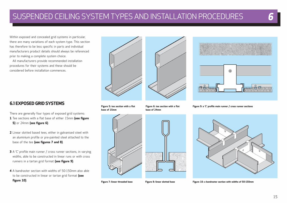
There are generally four types of exposed grid systems:
1 Tee sections with a flat base of either 15mm (see figure
5) or 24mm (see figure 6).
2 Linear slotted based tees, either in galvanised steel with
an aluminium profile or pre-painted steel attached to the
base of the tee (see figures 7 and 8).
3 A ‘C’ profile main runner / cross runner sections, in varying
widths, able to be constructed in linear runs or with cross
runners in a tartan grid format (see figure 9).
4 A bandraster section with widths of 50-150mm also able
to be constructed in linear or tartan grid format (see
figure 10).
Figure 6: tee section with a flat base of 24mm
Figure 5: tee section with a flat base of 15mm
Figure 7: linear threaded base Figure 8: linear slotted base
Figure 9: a ‘C’ profile main runner / cross runner sections
Figure 10: a bandraster section with widths of 50-150mm
SUSPENDED CEILING SYSTEM TYPES AND INSTALLATION PROCEDURES 6
16
Types 1 and 2Main runners should be installed to manufacturer’s
recommendations. These generally call for the hanger to be
fixed to the stalk of the main runner so that they are
installed to the required level (see 5.2) with supports required
within 450mm of the perimeter wall and 150mm of the main
runner splice. Jointing of main runners should be staggered
throughout the area. Levelling must be done with the
supporting hangers taut to prevent any subsequent
downward movement when the ceiling loads are applied.
Kinks or bends must not be made in hanger wire as a means
of levelling the main runners.
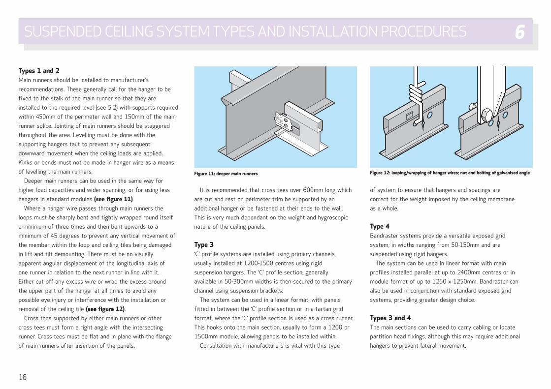
Deeper main runners can be used in the same way for
higher load capacities and wider spanning, or for using less
hangers in standard modules (see figure 11).
Where a hanger wire passes through main runners the
loops must be sharply bent and tightly wrapped round itself
a minimum of three times and then bent upwards to a
minimum of 45 degrees to prevent any vertical movement of
the member within the loop and ceiling tiles being damaged
in lift and tilt demounting. There must be no visually
apparent angular displacement of the longitudinal axis of
one runner in relation to the next runner in line with it.
Either cut off any excess wire or wrap the excess around
the upper part of the hanger at all times to avoid any
possible eye injury or interference with the installation or
removal of the ceiling tile (see figure 12).
Cross tees supported by either main runners or other
cross tees must form a right angle with the intersecting
runner. Cross tees must be flat and in plane with the flange
of main runners after insertion of the panels.
It is recommended that cross tees over 600mm long which
are cut and rest on perimeter trim be supported by an
additional hanger or be fastened at their ends to the wall.
This is very much dependant on the weight and hygroscopic
nature of the ceiling panels.
Type 3‘C’ profile systems are installed using primary channels,
usually installed at 1200-1500 centres using rigid
suspension hangers. The ‘C’ profile section, generally
available in 50-300mm widths is then secured to the primary
channel using suspension brackets.
The system can be used in a linear format, with panels
fitted in between the ‘C’ profile section or in a tartan grid
format, where the ‘C’ profile section is used as a cross runner.
This hooks onto the main section, usually to form a 1200 or
1500mm module, allowing panels to be installed within.
Consultation with manufacturers is vital with this type
of system to ensure that hangers and spacings are
correct for the weight imposed by the ceiling membrane
as a whole.
Type 4Bandraster systems provide a versatile exposed grid
system, in widths ranging from 50-150mm and are
suspended using rigid hangers.
The system can be used in linear format with main
profiles installed parallel at up to 2400mm centres or in
module format of up to 1250 x 1250mm. Bandraster can
also be used in conjunction with standard exposed grid
systems, providing greater design choice.
Types 3 and 4The main sections can be used to carry cabling or locate
partition head fixings, although this may require additional
hangers to prevent lateral movement.
Figure 11: deeper main runners Figure 12: looping/wrapping of hanger wires; nut and bolting of galvanised angle
SUSPENDED CEILING SYSTEM TYPES AND INSTALLATION PROCEDURES 6
17
Hold down clips can be used to retain the panels in
the grid particularly in small rooms, stairwells, entrance /
reception areas where wind or air pressure may be prevalent,
also for security reasons. A means of reducing potential
pressure build up should be considered, eg allowing air to
dissipate through lights or grilles. Where access is required
the panels would not normally be clipped. Clips should be
spaced according to the manufacturer’s recommendations.
Non-removable panel hold down clips may have to be used
in the case of a ceiling being required to provide structural
fire resistance. In the case of cutting tegular or rebated
edged tiles there are two alternative methods:
1 If the face of the grid and the perimeter trim are required
to be at the same level, the tile edge should be site
reformed to the rebated detail using an appropriate tool.
2 If the face of the tile and the perimeter trim need to be at
the same level (ie the grid face is higher) then the ends of
the tees should be supported by perimeter blocks (wedges).
Panels cut at perimeters must be trimmed to the full
space between the last grid member and the perimeter trim
to prevent subsequent movement (see 6.9).
Where the reformed tile edge is visible, it may be necessary
to paint the edge with paint from the ceiling tile manufacturer.
Panels must only be handled by their edges to avoid soiling,
preferably by wearing white cotton gloves. Ceiling layouts
should be arranged so that panels less than one half width do
not occur unless otherwise directed by reflected ceiling plans
or job conditions.
An enhanced corrosion resistant grid system should be
used in harsh environments, eg swimming pools, kitchens and
where atmospheric conditions regularly exceed 90-95%
relative humidity, or if the environment is such that
occupants have to take special precautions (ie protective
clothing, masks). Also, if areas are to be subject to a high
pressure cleaning regime, then this grid should be used.
6.2 CONCEALED GRID SYSTEMS
A variety of concealed ceiling systems is available that
suit metal, mineral wool, gypsum, rock and glass wool
products.
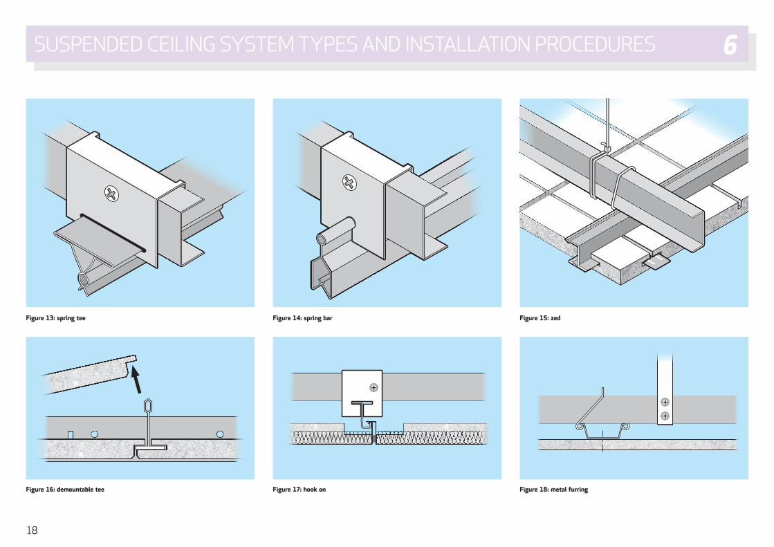
Systems generally incorporate a primary steel channel,
from which zed, tee, hook, spring tee, spring bar, furring
or other channel sections are then mechanically fixed or
clipped at 90 degrees to form a fixing base for the
relevant ceiling tiles (see figures 13 to 18 overleaf).
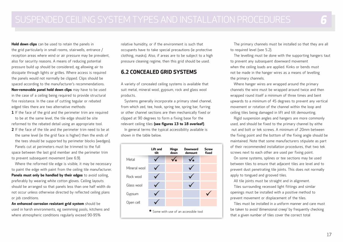
In general terms the typical accessibility available is
shown in the table below.
The primary channels must be installed so that they are all
to required level (see 5.2).
The levelling must be done with the supporting hangers taut
to prevent any subsequent downward movement
when the ceiling loads are applied. Kinks or bends must
not be made in the hanger wires as a means of levelling
the primary channels.
Where hanger wires are wrapped around the primary
channels the wire must be wrapped around twice and then
wrapped round itself a minimum of three times and bent
upwards to a minimum of 45 degrees to prevent any vertical
movement or rotation of the channel within the loop and
ceiling tiles being damaged in lift and tilt demounting.
Rigid suspension angles and hangers are more commonly
used, and should be fixed to the primary channel by eithe
nut and bolt or tek screws. A minimum of 20mm between
the fixing point and the bottom of the fixing angle should be
maintained. Note that some manufacturers stipulate as part
of their recommended installation procedures, that two tek
screws next to each other are used per fixing point.
On some systems, splines or tee sections may be used
between tiles to ensure that adjacent tiles are level and to
prevent dust penetrating tile joints. This does not normally
apply to tongued and grooved tiles.
All tile joints must be straight and in alignment.
Tiles surrounding recessed light fittings and similar
openings must be installed with a positive method to
prevent movement or displacement of the tiles.
Tiles must be installed in a uniform manner and care must
be taken to avoid ‘dimensional creep’ by frequently checking
that a given number of tiles cover the correct total
Lift and tilt
Hinge down
Downward demount
Screw fixed
Metal * *
Mineral wool Rock wool Glass wool Gypsum Open cell
* Some with use of an accessible tool
SUSPENDED CEILING SYSTEM TYPES AND INSTALLATION PROCEDURES 6
18
Figure 13: spring tee Figure 14: spring bar Figure 15: zed
Figure 16: demountable tee Figure 17: hook on Figure 18: metal furring
SUSPENDED CEILING SYSTEM TYPES AND INSTALLATION PROCEDURES 6
19
dimension (see 4.5). It is recommended that a reasonable
proportion of loose laid tiles are initially fixed to maintain
alignment.
Removal and replacement of metal ceiling panels must be
carried out correctly to avoid permanent damage through
denting or twisting. Removal of tiles from clip in systems
must only be done with special tools.
6.3 ACOUSTIC INFILLS FOR USE IN METAL CEILINGS
A range of acoustic infills are available to achieve numerous
acoustic performance levels to suit client requirements.
When perforated acoustic metal tiles are used the
acoustic pad must be fitted carefully into the back of the
tile to prevent upward air movement through the panel
which could cause pattern staining.
For the same reason particular care is required to ensure
that pads in cut perimeter tiles are cut to the full panel size.
All cut infill pads, whether for perimeter or for cut tiles
should be re-sealed along cut edges.
6.4 STRETCH / TENSIONED CEILINGS
A stretch / tensioned ceiling is a suspended ceiling system
generally consisting of two components: a perimeter profile
and a lightweight stretch fabric membrane or tensile fabric
which is either stretched or tensioned into the perimeter
profile – ie the system is suspended from its perimeter and
not from overhead as traditional suspended ceilings.
These types of ceilings can also be used to create suspended
lighting / feature rafts and island features within traditional
suspended ceilings (see 6.6).
Due to the flexible nature of the membrane they can be
formed into virtually any shape.
These ceilings allow the incorporation of light fixtures, grilles,
sprinklers etc, but as they are non-load bearing these items
must be independently supported from above.
All apertures for lighting, grilles, sprinklers and other services
are formed on site and may require proprietary supporting
trims, frames or pattresses.
Generally, the membrane will be formed from rolls or sheet
fabrics up to 2.4m wide with small ultrasonic, stitched or thermo-
welded seams depending on the type of fabric used. Each
manufacturer of these systems will normally have a maximum
overall sheet size of between 50m2 and 60m2.
If the area to receive the ceiling exceeds the maximum sheet
size then two or more sheets will be needed, joined together
by fully or semi-concealed joining profiles that may require
support from above.
Depending on the fabric used, perimeter track / profiles
should be fixed to perimeter walls with suitable fixings capable
of up to 30kg per linear metre tension (refer to individual
manufacturer). Where the fixing is to plasterboard, securely
fixed timber or metal grounds should be provided. It is
recommended decorated walls have their first coat applied, tiled
walls are grouted and all plastering is completed and dried prior
to the installation of the perimeter tracks / profiles.
Installation of some of the fabric membranes requires the
raising of the air temperature by the use of propane gas
heaters to approximately 38°C in the operational area by the
installer of the ceiling. In winter the areas to be fitted with
these ceilings must be heated prior to and after installation to
a minimum temperature specified by the manufacturer of the
system for the different fabric material fitted.
Different manufacturers may have varying procedures
and recommendations due to the fabrics and tracks /
profiles selected.
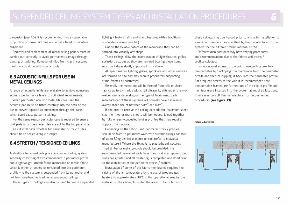
For occasional access to the void these ceilings are fully
demountable by ‘unclipping’ the membrane from the perimeter
profile and then ‘re-clipping’ it back into the perimeter profile.
For frequent access to the void it is recommended that
demountable frames are formed out of the clip in profile and
membrane are inserted into the system at required locations.
In all cases consult the manufacturer for recommended
procedures (see figure 19).
Figure 19: stretch
SUSPENDED CEILING SYSTEM TYPES AND INSTALLATION PROCEDURES 6
20
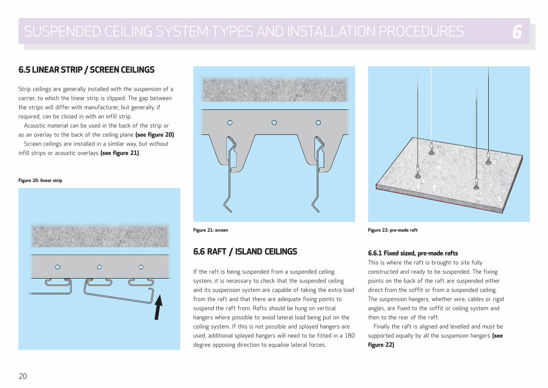
6.5 LINEAR STRIP / SCREEN CEILINGS
Strip ceilings are generally installed with the suspension of a
carrier, to which the linear strip is clipped. The gap between
the strips will differ with manufacturer, but generally, if
required, can be closed in with an infill strip.
Acoustic material can be used in the back of the strip or
as an overlay to the back of the ceiling plane (see figure 20).
Screen ceilings are installed in a similar way, but without
infill strips or acoustic overlays (see figure 21).
6.6 RAFT / ISLAND CEILINGS
If the raft is being suspended from a suspended ceiling
system, it is necessary to check that the suspended ceiling
and its suspension system are capable of taking the extra load
from the raft and that there are adequate fixing points to
suspend the raft from. Rafts should be hung on vertical
hangers where possible to avoid lateral load being put on the
ceiling system. If this is not possible and splayed hangers are
used, additional splayed hangers will need to be fitted in a 180
degree opposing direction to equalise lateral forces.
6.6.1 Fixed sized, pre-made raftsThis is where the raft is brought to site fully
constructed and ready to be suspended. The fixing
points on the back of the raft are suspended either
direct from the soffit or from a suspended ceiling.
The suspension hangers, whether wire, cables or rigid
angles, are fixed to the soffit or ceiling system and
then to the rear of the raft.
Finally the raft is aligned and levelled and must be
supported equally by all the suspension hangers (see
figure 22).
Figure 20: linear strip
Figure 21: screen Figure 22: pre-made raft
SUSPENDED CEILING SYSTEM TYPES AND INSTALLATION PROCEDURES 6
21
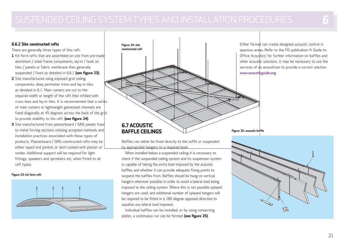
6.6.2 Site constructed raftsThere are generally three types of this raft:
1 Kit form rafts that are assembled on site from pre-made
aluminium / steel frame components, lay-in / hook on
tiles / panels or fabric membrane then generally
suspended / fixed as detailed in 6.6.1 (see figure 23).
2 Site manufactured using exposed grid ceiling
components, deep perimeter trims and lay-in tiles
as detailed in 6.1. Main runners are cut to the
required width or length of the raft then infilled with
cross tees and lay-in tiles. It is recommended that a series
of main runners or lightweight galvanised channels are
fixed diagonally at 45 degrees across the back of the grid
to provide stability to the raft. (see figure 24).
3 Site manufactured from plasterboard / GRG panels fixed
to metal furring sections utilising accepted methods and
installation practices associated with these types of
products. Plasterboard / GRG constructed rafts may be
either taped and jointed, or skim coated with plaster or
render. Additional support will be required for light
fittings, speakers and sprinklers etc, when fitted to all
raft types.
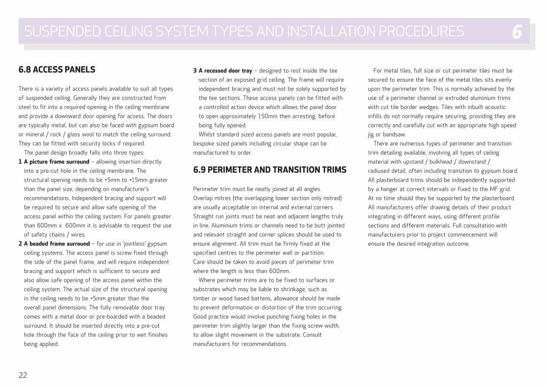
6.7 ACOUSTIC BAFFLE CEILINGS
Baffles can either be fixed directly to the soffit or suspended
by appropriate hangers to a required level.
When installed below a suspended ceiling it is necessary to
check if the suspended ceiling system and its suspension system
is capable of taking the extra load imposed by the acoustic
baffles and whether it can provide adequate fixing points to
suspend the baffles from. Baffles should be hung on vertical
hangers wherever possible in order to avoid a lateral load being
imposed to the ceiling system. Where this is not possible splayed
hangers are used, and additional number of splayed hangers will
be required to be fitted in a 180 degree opposed direction to
equalise any lateral load imposed.
Individual baffles can be installed, or by using connecting
plates, a continuous run can be formed (see figure 25).
Either format can create designed acoustic control in
spacious areas. Refer to the FIS publication ‘A Guide to
Office Acoustics’ for further information on baffles and
other acoustic solutions. It may be necessary to use the
services of an acoustician to provide a correct solution.
www.acousticguide.org
Figure 23: kit form raft
Figure 24: site constructed raft
Figure 25: acoustic baffle
SUSPENDED CEILING SYSTEM TYPES AND INSTALLATION PROCEDURES 6
22
6.8 ACCESS PANELS
There is a variety of access panels available to suit all types
of suspended ceiling. Generally they are constructed from
steel to fit into a required opening in the ceiling membrane
and provide a downward door opening for access. The doors
are typically metal, but can also be faced with gypsum board
or mineral / rock / glass wool to match the ceiling surround.
They can be fitted with security locks if required.
The panel design broadly falls into three types:
1 A picture frame surround – allowing insertion directly
into a pre-cut hole in the ceiling membrane. The
structural opening needs to be +5mm to +15mm greater
than the panel size, depending on manufacturer’s
recommendations. Independent bracing and support will
be required to secure and allow safe opening of the
access panel within the ceiling system. For panels greater
than 600mm x 600mm it is advisable to request the use
of safety chains / wires.
2 A beaded frame surround – for use in ‘jointless’ gypsum
ceiling systems. The access panel is screw fixed through
the side of the panel frame, and will require independent
bracing and support which is sufficient to secure and
also allow safe opening of the access panel within the
ceiling system. The actual size of the structural opening
in the ceiling needs to be +5mm greater than the
overall panel dimensions. The fully removable door tray
comes with a metal door or pre-boarded with a beaded
surround. It should be inserted directly into a pre-cut
hole through the face of the ceiling prior to wet finishes
being applied.
3 A recessed door tray – designed to rest inside the tee
section of an exposed grid ceiling. The frame will require
independent bracing and must not be solely supported by
the tee sections. These access panels can be fitted with
a controlled action device which allows the panel door
to open approximately 150mm then arresting, before
being fully opened.
Whilst standard sized access panels are most popular,
bespoke sized panels including circular shape can be
manufactured to order.
6.9 PERIMETER AND TRANSITION TRIMS
Perimeter trim must be neatly joined at all angles.
Overlap mitres (the overlapping lower section only mitred)
are usually acceptable on internal and external corners.
Straight run joints must be neat and adjacent lengths truly
in line. Aluminium trims or channels need to be butt jointed
and relevant straight and corner splices should be used to
ensure alignment. All trim must be firmly fixed at the
specified centres to the perimeter wall or partition.
Care should be taken to avoid pieces of perimeter trim
where the length is less than 600mm.
Where perimeter trims are to be fixed to surfaces or
substrates which may be liable to shrinkage, such as
timber or wood based battens, allowance should be made
to prevent deformation or distortion of the trim occurring.
Good practice would involve punching fixing holes in the
perimeter trim slightly larger than the fixing screw width,
to allow slight movement in the substrate. Consult
manufacturers for recommendations.
For metal tiles, full size or cut perimeter tiles must be
secured to ensure the face of the metal tiles sits evenly
upon the perimeter trim. This is normally achieved by the
use of a perimeter channel or extruded aluminium trims
with cut tile border wedges. Tiles with inbuilt acoustic
infills do not normally require securing, providing they are
correctly and carefully cut with an appropriate high speed
jig or bandsaw.
There are numerous types of perimeter and transition
trim detailing available, involving all types of ceiling
material with upstand / bulkhead / downstand /
radiused detail, often including transition to gypsum board.
All plasterboard trims should be independently supported
by a hanger at correct intervals or fixed to the MF grid.
At no time should they be supported by the plasterboard.
All manufacturers offer drawing details of their product
integrating in different ways, using different profile
sections and different materials. Full consultation with
manufacturers prior to project commencement will
ensure the desired integration outcome.
SUSPENDED CEILING SYSTEM TYPES AND INSTALLATION PROCEDURES 6
23
Suspended ceilings can help to fulfil the fire requirements of
the Building Regulations as follows:
a To contribute to the fire resistance of structural steelwork
supporting a non-combustible floor.
b To provide added resistance to a combustible floor such
as timber to enable it to satisfy the fire requirements of
the Building Regulations.
c To increase the safety in escape routes to a degree where
they may be classified as protected routes.
d In addition it may be necessary to install cavity barriers in
the ceiling void to satisfy Building Regulations Approved
Document B.
7.1 STRUCTURAL FIRE RESISTANCE
Should a suspended ceiling be intended to contribute to
the structural fire resistance of a building, the tendering
specialist contractors must be informed. Such ceilings may
require specific materials and will need particular
construction details.
Suspended ceilings that are installed for the purpose of
structural fire resistance must conform in every respect to
the details of the test carried out under BS EN 13501-2002.
It is therefore essential that the specialist contractor has a
copy of the relevant test certificate or letter of assessment
which has been issued in lieu. Drawings showing construction
details should be approved by an authorised member of the
professional team before ceiling installation commences.
The ceiling installation must conform in every respect with
the tested or assessed design.
Any proposed deviation from the tested system must be
subjected to evaluation by a competent authority. Re-testing
may be necessary. All parties should ensure that that the
test report for the specified system is still valid.
Work should be undertaken by contractors with
experience of such installations, using operatives with full
understanding of the fixing requirements.
7.1.1 Integrity of the grid assemblyTo ensure integrity of the ceiling assembly the grid and all
supporting members and fixings should be of non-
combustible materials and preferably of steel.
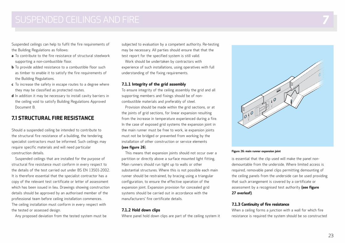
Provision should be made within the grid sections, or at
the joints of grid sections, for linear expansion resulting
from the increase in temperature experienced during a fire.
In the case of exposed grid systems the expansion joint in
the main runner must be free to work, ie expansion joints
must not be bridged or prevented from working by the
installation of other construction or service elements
(see figure 26).
This means that expansion joints should not occur over a
partition or directly above a surface mounted light fitting.
Main runners should run tight up to walls or other
substantial structures. Where this is not possible each main
runner should be restrained, by bracing using a triangular
configuration, to ensure the effective operation of the
expansion joint. Expansion provision for concealed grid
systems should be carried out in accordance with the
manufacturers’ fire certificate details.
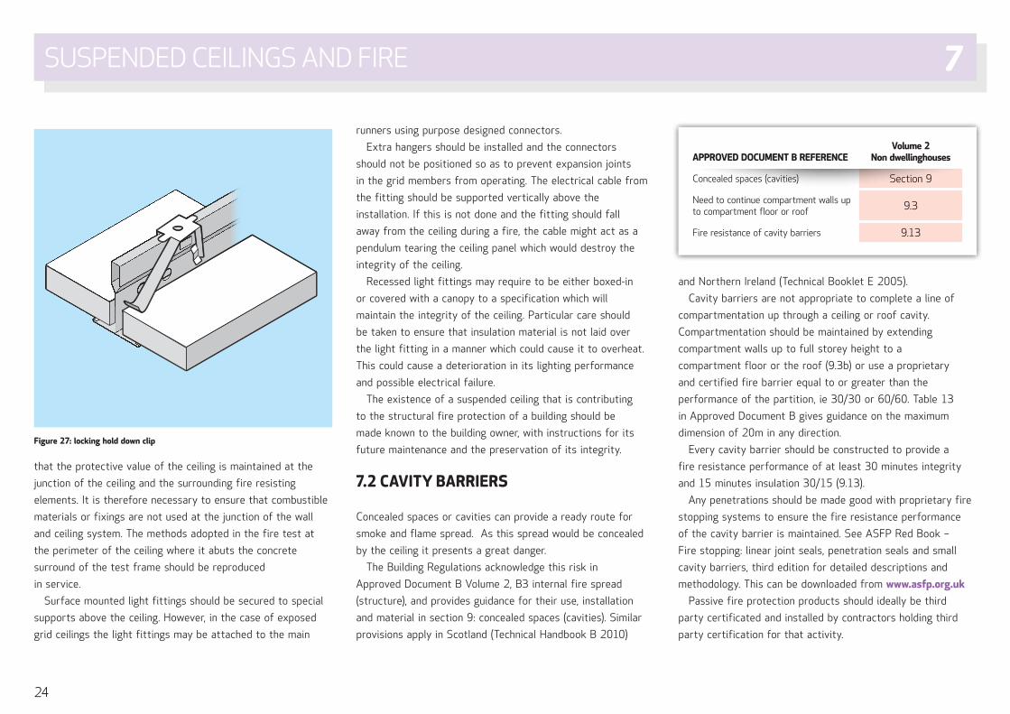
7.1.2 Hold down clipsWhere panel hold down clips are part of the ceiling system it
is essential that the clip used will make the panel non-
demountable from the underside. Where limited access is
required, removable panel clips permitting demounting of
the ceiling panels from the underside can be used providing
that such arrangement is covered by a certificate or
assessment by a recognised test authority (see figure
27 overleaf).
7.1.3 Continuity of fire resistanceWhen a ceiling forms a junction with a wall for which fire
resistance is required the system should be so constructed
Figure 26: main runner expansion joint
SUSPENDED CEILINGS AND FIRE 7
24
that the protective value of the ceiling is maintained at the
junction of the ceiling and the surrounding fire resisting
elements. It is therefore necessary to ensure that combustible
materials or fixings are not used at the junction of the wall
and ceiling system. The methods adopted in the fire test at
the perimeter of the ceiling where it abuts the concrete
surround of the test frame should be reproduced
in service.
Surface mounted light fittings should be secured to special
supports above the ceiling. However, in the case of exposed
grid ceilings the light fittings may be attached to the main
runners using purpose designed connectors.
Extra hangers should be installed and the connectors
should not be positioned so as to prevent expansion joints
in the grid members from operating. The electrical cable from
the fitting should be supported vertically above the
installation. If this is not done and the fitting should fall
away from the ceiling during a fire, the cable might act as a
pendulum tearing the ceiling panel which would destroy the
integrity of the ceiling.
Recessed light fittings may require to be either boxed-in
or covered with a canopy to a specification which will
maintain the integrity of the ceiling. Particular care should
be taken to ensure that insulation material is not laid over
the light fitting in a manner which could cause it to overheat.
This could cause a deterioration in its lighting performance
and possible electrical failure.
The existence of a suspended ceiling that is contributing
to the structural fire protection of a building should be
made known to the building owner, with instructions for its
future maintenance and the preservation of its integrity.
7.2 CAVITY BARRIERS
Concealed spaces or cavities can provide a ready route for
smoke and flame spread. As this spread would be concealed
by the ceiling it presents a great danger.
The Building Regulations acknowledge this risk in
Approved Document B Volume 2, B3 internal fire spread
(structure), and provides guidance for their use, installation
and material in section 9: concealed spaces (cavities). Similar
provisions apply in Scotland (Technical Handbook B 2010)
and Northern Ireland (Technical Booklet E 2005).
Cavity barriers are not appropriate to complete a line of
compartmentation up through a ceiling or roof cavity.
Compartmentation should be maintained by extending
compartment walls up to full storey height to a
compartment floor or the roof (9.3b) or use a proprietary
and certified fire barrier equal to or greater than the
performance of the partition, ie 30/30 or 60/60. Table 13
in Approved Document B gives guidance on the maximum
dimension of 20m in any direction.
Every cavity barrier should be constructed to provide a
fire resistance performance of at least 30 minutes integrity
and 15 minutes insulation 30/15 (9.13).
Any penetrations should be made good with proprietary fire
stopping systems to ensure the fire resistance performance
of the cavity barrier is maintained. See ASFP Red Book –
Fire stopping: linear joint seals, penetration seals and small
cavity barriers, third edition for detailed descriptions and
methodology. This can be downloaded from www.asfp.org.uk
Passive fire protection products should ideally be third
party certificated and installed by contractors holding third
party certification for that activity.
Figure 27: locking hold down clip
APPROVED DOCUMENT B REFERENCEVolume 2
Non dwellinghouses
Concealed spaces (cavities) Section 9
Need to continue compartment walls up to compartment floor or roof 9.3
Fire resistance of cavity barriers 9.13
SUSPENDED CEILINGS AND FIRE 7

25
8.1 SUSTAINABILITY
All construction projects over a certain value will have a
sustainability / carbon footprint agenda which will have
to be embraced by all specialist contractors to share in
the process.
As a best practice principle, all specialist contractors
should have an ongoing carbon footprint reduction
programme, which can then become applicable on
all projects.
This will include the disposal of all materials from the
strip out, and offcuts from the installation. Materials
may be selected to comply with systems that are designed
to measure the environmental impact of the fit out such as
BREEAM, LEED or Ska (see page 26).
8.2 HEALTH AND SAFETY
To conform to the Health & Safety at Work Act 1974 the
specialist contractor and main contractor must provide a
method statement and risk assessment of the work that
has to be undertaken on each project. All members of the
construction team have a duty of care to their site colleagues.
Working to agreed programmes and to formalised method
statements can contribute to site safety. Identifying hazards
and assessing potential risks should cover the working
environment, the work to be done, the tools and equipment
to be used and the materials to be installed.
Guidance can be sought from the ‘FIS Health & Safety
Handbook’ and also the ‘FIS Site Guide for Suspended
Ceilings’, which has particular reference to working at height.
8.3 OPERATION AND MAINTENANCE (O&M) MANUALS
When work has been completed, it is good practice to obtain
signatures from the main contractor on a completion /
handover certificate, to avoid later disputes on any damage
subsequently caused by other trades.
If required by the terms of engagement, the main
contractor must provide, either in paper form or more
commonly via computer files, information relevant to the
installation that has been carried out.
Typically this includes:
• Products installed
• ‘As built’ drawings
• Manufacturers’ product information, including source of
replacement material, and advice on cleaning, maintenance,
repair and disposal of materials for recycling at end of life
• Acoustic and fire performance details
• Details of any special elements to the project
• Advice on removal and replacement of tiles
• Relevant COSHH data.
Maintenance• With the exception of gypsum ceilings, most ceiling panels
or tiles are factory finished and require no further
decoration at the time of installation
• Cleaning should be carried out in accordance with
manufacturer’s recommendations
• Soiled ceilings can be cleaned by chemical spray methods
available through specialist cleaning companies. In situ
redecoration of some ceilings is possible. Before
undertaking this, the effects on the acoustic and fire
performance / characteristics should be considered.
The O&M manual is left with the main contractor who in
turn makes it available to the client.
CONTRACTING SUPPORT ADMINISTRATION 8
26
BREEAMBREEAM is an environmental assessment method and rating
system for buildings. Launched in 1990, it sets the standard
for best practice in sustainable building design, construction
and operation and has become one of the most
comprehensive and widely recognised measures of a
building's environmental performance.
A BREEAM assessment uses recognised measures of
performance, which are set against established benchmarks,
to evaluate a building’s specification, design, construction
and use. The measures used represent a broad range of
categories and criteria from energy to ecology. They include
aspects related to energy and water use, the internal
environment (health and well-being), pollution, transport,
materials, waste, ecology and management processes.
www.breeam.org
LEEDLeadership in Energy and Environmental Design (LEED) is
a third-party certification program for buildings. It is a
nationally accepted organisation for design, operation and
construction of high performance green buildings. This
ensures the buildings are environmentally compatible,
provide a healthy work environment and are profitable.
LEED New Construction buildings are awarded points for
sustainability for things like energy-efficient lighting, low-
flow plumbing fixtures and collection of water. Recycled
construction materials and energy efficient appliances also
impact the point rating system.
www.leed.net
SkaLead and owned by the Royal Institution of Chartered
Surveyors (RICS) the Ska Rating is an assessment method,
benchmark and standard for non-domestic fit outs. It helps
landlords and tenants assess fit out projects against a set of
sustainability good practice criteria.
Ska Offices is used on fit out projects large and small,
both refurbishment and new build, and it scores
environmental good practice irrespective of the base
building. The offices scheme consists of 104 individual good
practice measures covering Energy and CO2 Emissions,
Waste, Water, Materials, Pollution, Wellbeing and Transport.
Ska Retail is currently under development.
This guidance is freely available along with an online
assessment tool, which can be used informally or for formal
certification using an RICS Ska Rating Accredited Assessor.
Assessments can be carried out at three stages: design,
handover and occupancy.
FIS is a Ska development partner.
www.rics.org/ska
GLOSSARY 9

27
ACKNOWLEDGEMENTS 10
FIS would like to extend its thanks to those FIS members and other professionals and specialists who gave generously of their valuable time and expertise to make this publication possible.
FIS has grown over the past 50 years to become the leading
trade association for the interiors fit out sector of the
construction industry. FIS represents companies involved in
the manufacture, supply and installation of all aspects of
interior fit outs and refurbishment.
FIS members operate in retail and commercial offices,
the public sector, banks and building societies, hotels and
leisure, airports, hospitals, and so on. Most work nationally
and an increasing number operate in Europe and beyond.
Quality and integrity lie at the heart of FIS’s philosophy
- each member is expected to act with the utmost
integrity, and to exercise the highest standards of business
practice and workmanship. At the same time, the Association
seeks to continually raise, maintain and ensure the
perpetuation of standards in order to remain a source of
quality membership.
fIS membership is not automatic and applicants are subject
to strict vetting procedures on application, as well as ongoing
vetting. In the case of contractors, this includes inspection of
recent contracts to assess workmanship standards.
www.thefis.org
ISBN 978-0-9565341-2-5
BEST PRACTICE GUIDE INSTALLATION OF SUSPENDED CEILINGS
FISOlton Bridge245 Warwick RoadSolihullWest MidlandsB92 7AH
+44(0)121 707 [email protected]