best practice guide pressure systems · spraying and placing machines ... instruction manual is...
TRANSCRIPT

Best Practice Guide – Pressure Systems Page 1 of 54
BEST PRACTICE GUIDEPRESSURE SYSTEMS
ENERGISED SYSTEMS
EA501_H&S_LM
MOVING LONDON FORWARD
A response to risks identifi ed on construction sites working with pressure systems

Best Practice Guide – Pressure Systems Page 1 of 54
A best practice guide produced in collaboration between
AcknowledgementsThe Pressure Systems Booklet has been developed in collaboration with the above key industry stakeholders.
This booklet will be reviewed at intervals, and any amendments arising
from the review will be published in an amended version. This document does not purport to include all the necessary provisions of a contract. Users are responsible for its correct application.

Best Practice Guide – Pressure Systems Page 2 of 54Page 2 of 54Best Practice Guide – Pressure Systems Page 2 of 54
IndexIntroductionPreface and Purpose 3Best Practice Guide - Pressure Systems 3
Part A – PlanningConcrete Pumping and Spray Concrete Lining (SCL) 6Jet Wash Operations 7Single Sourcing Components 8
Part B – Competency / TrainingSelection 12Training 12Best Practice - Sprayed Concrete Lining 16
Part C – Execution and ControlConcrete Pumping and Spray Concrete Lining 18Pump Set-up 18Concrete Delivery area 18Receiving hopper and hopper guarding 19Operational safety zone 19Delivery Pipeline Set-up 19Pipe Clamps 20Pipeline Movement 21End-hose 21End-hose and reducer combination 21During Pumping Operations 22Hose-whip 22Controls which reduces likelihood of hose-whip 23Cleaning / Blowing Out 24Pipeline 24Best Practice Concrete - ‘Blow-out’ Chambers with Exclusion Zones 25Best Practice - Protection of concrete fl exi-hoses 27Pressure Wash Operations 28Jet Washing / Pressure washers 37
Part D - Inspection and MaintenanceConcrete Pumping 32Concrete Pump Examination and testing 32Concrete Pump Maintenance 33Pipeline Components 33Best Practice - High Pressure Hose Compensation Grouting 35Best Practice - Safetrak Electronic Inspection 36
AppendicesA. Concrete Pumping Operation Check Sheet 40B. Concrete pipe Blow Out Check Sheet 42 C. Cleaning Concrete Lines with Compressed Air 44D. Jet Washing Operation Check Sheet 47E. Examination Checklist for Concrete Pumps 49F. Crossrail Vehicle Safety Kit 50G. References 53

IntroductionPrefaceThe Crossrail project consists of multiple work sites and contractors where exposure to pressurised systems and stored energy release is signifi cant. This guide brings together information collected in response to risks identifi ed on Crossrail construction sites, to ensure pressurised systems are operated safely across the Crossrail project.
This document has been produced by consolidating the specialist knowledge from the Crossrail Contractors, JVs, supply chain and industry partners identifi ed on Page 2 of this document.
PurposePressure Systems are defi ned as:
1. A system comprising of one or more pressure vessels of rigid construction, any associated pipework and protective devices
2. The pipework with its protective devices to which a transportable pressure receptacle is, or is intended to be, connected
3. A pipeline and its protective devices which contain or is liable to contain a “relevant fl uid”.
The principal causes of pressure-related incidents are:
• Poor design, installation and/or maintenance of equipment
• Inadequate repairs or modifi cations to the equipment
• An unsafe system of work
• Operator error
• Poor training/supervision.
The main hazards from pressure are:
• Impact from the blast of an explosion or release of compressed liquid or gas under pressure
• Impact from parts of equipment that fail or any fl ying debris
• Contact with the released liquid or gas, such as steam
• Fire resulting from the escape of fl ammable liquids or gases.
This Best Practice Guide suggests minimum requirements for the safe use of pressure systems, provides best practice, competency and training guidance.
Best Practice Guide—Pressure SystemsThis Best Practice Guide applies to all personnel with an involvement with the procurement, operation and supervision of pressurised working systems and stored energy release; the guide specifi cally covers the following types of Pressurised Systems: Concrete Pumping, Spray Concrete Lining (SCL), Grouting, Compressed Air and Jet/Pressure Washing.
The aim of this document is to raise awareness of the consequences of working with pressurised and storage energy release systems and promote a safer working environment for all operatives working on Crossrail.
Best Practice Guide – Pressure Systems Page 3 of 54

This Best Practice Guide should be used alongside:
• Pressure Equipment Regulations 1999 (PER)
• Pressure Systems Safety Regulations 2000 (PSSR)
• Provision and use of Work Equipment Regulations 1998 (PUWER)
• BS EN 12001:2012, Conveying, spraying and placing machines for concrete and mortar—Safety requirements
• BS 8476:2007, Code of Practice for Safe Use of Concrete Pumps 2012.
Best Practice Guide – Pressure Systems Page 4 of 54
Best Practice Guide – Pressure Systems Page 5 of 54
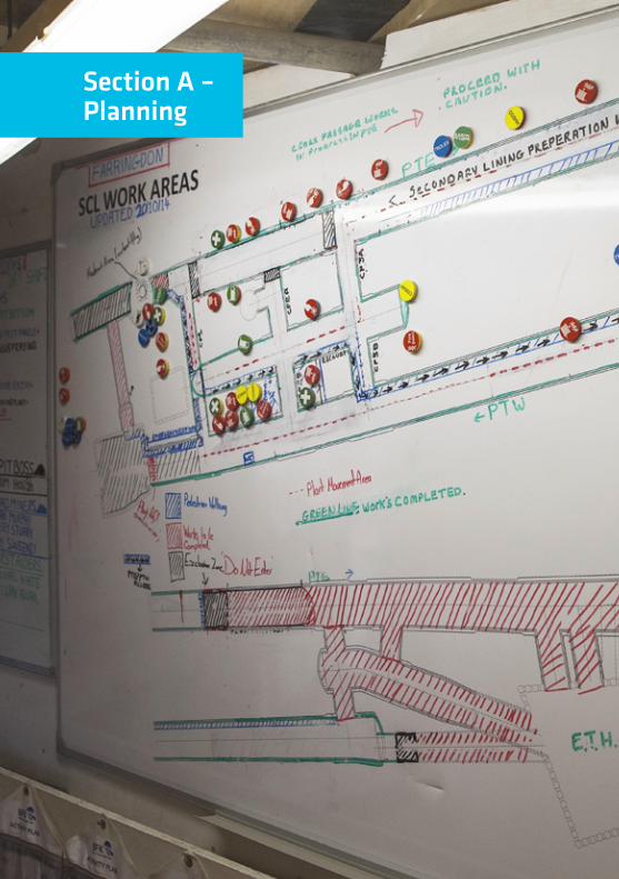
Section A –Planning

Best Practice Guide – Pressure Systems Page 6 of 54
Concrete Pumping and Spray Concrete Lining (SCL)Planning and preparation are essential in order to ensure that concrete pumping and sprayed concrete lining is done safely. In order to maintain awareness and ensure suffi cient resources are made available, it is recommended that regular planning meetings are held. At these meetings, consideration should be given to ensure that:
People
• The pump operator is competent, qualifi ed and experienced
• There is a suffi cient number of competent, qualifi ed and experienced operatives, including a competent person, present at all times
• Appropriate personal protective equipment is worn and other relevant safety equipment is available as necessary.
Plant
• The concrete pump is suitable to complete the pour safely and within the required time frame
• The location of the pump is suitable taking account of the footprint of the pump, the ground conditions and the access / egress requirements for delivery trucks
• A relevant, up to date operating instruction manual is with both the pump and the boom
• Relevant, up to date maintenance/ repair manuals are with the pump
• Up to date, maintenance log books and parts catalogue are with the pump and boom
• Maintenance and repairs to the equipment are only carried out by competent, qualifi ed and experienced personnel who have been authorized to carry out the work
• The couplings are suitable and of a consistent type across the system, of higher pressure rating than the pump, are complete with a seal and safety pin and are clean and undamaged
• The pipeline is fi xed on both the horizontal and vertical runs and that the brackets used are adequate for the task, clean and undamaged
Process
• There is an understanding of events or circumstances that would require the operation to be stopped
• There is an agreed sequence of steps to be carried out to ensure complete and safe stoppage
• There is an understanding of the impact of stoppages on other operations
• There is an understanding of the impact of other operations on the pressure system
• There has been an assessment of manual tasks that may cause muscle/ ligament strains or other injuries
• There is safe access eliminating trip, slip and fall hazards

Best Practice Guide – Pressure Systems Page 7 of 54
• All systems of work comply with electrical safety legislation
• Whether enough operatives are available, including a competent person being present at all times
• Events or circumstances that would require the operation to be stopped
• The pipeline is suitable to complete the pour safely and within the required time frame, the wall thickness is suffi cient to withstand the maximum pressure that the pump can exert and the pipeline must be clean and undamaged
• The end placing hoses are suitable to complete the pour safely and within the required time frame—they are of higher pressure rating that the pump, clean and undamaged.
Jet Wash OperationsJet Wash operations have the potential to aff ect a large number of surrounding operations if not properly controlled. The following considerations during planning will result in a safer working environment for the operator and others in the area:
• Implement an exclusion zone around the operation with suffi cient safety signage to warn other operators
• The work area around the equipment should be clean and free of debris. Oil spillages result in slippery fl oors and must be cleaned up immediately
• Shield and bundle equipment hoses and cables so they do not obstruct the operator’s freedom of movement. Refer to Section D for further suggested control measures.
Personal Protective Equipment (PPE) Requirements:
PPE should always be regarded as the ‘last resort’, as it protects the operator without changing the level of hazard. Always consider that other control measures may be needed in addition to PPE which could reduce the level of protection needed from PPE. Standard PPE for operators should include:
Eye/Face Protection:
• Safety Glasses/Goggles/Face shield (EN 166 Class A or B). Goggles and face shields should be suitable to use with other PPE (helmets, hearing protection etc.).
What do operators do when visibility is reduced by splashes, mist or fog?
Systems of work should consider how this will be addressed.
Anti fogging googles/glasses are available, but try diff erent models fi rst to fi nd which performs best for your condition.
i

Best Practice Guide – Pressure Systems Page 8 of 54
Waterproof Clothing
• Waterproof safety boots (EN 345 or EN ISO 20345)
• Waterproof gloves: Operators need to ensure gloves are maintained and in good condition to ensure proper grip and personal hygiene
• Warm Clothing: The risk of finger blanching (due to reduced circulation of blood) increases at low temperatures. Operators working outdoors in cold weather should have adequate protection
• Safety helmet: (EN 397) or of higher standard if specified through risk assessment
• Hearing protection: (as identified by the Risk Assessment) to be worn at all times. Ear defenders should not be worn over clothing or PPE likely to interfere with the effectiveness of the defenders
• Respiratory Protection: if identified in the Risk Assessment for the activity, which must consider the possibility that the activity may generate a water mist / aerosol that contains harmful material.
Single Sourcing ComponentsSingle sourcing of components offers multiple benefits for an organisation, these benefits include:
• Reductions in product variation,
• Streamlined training is possible due to consistent product,
• Reduced downtime and inefficiencies caused by interoperability issues.
With regards to safety of pressurised systems components, the procurement of complete product/component ranges from a single, reputable manufacturer/supplier is highly recommended.
The hazards inherent in pressurised systems necessitates that all components of the system are compatible and securely fitted.
To ensure that single sourcing of components provide adequate risk control, the following additional checks are recommended:
• Ensure that detailed and complete product requirements are defined and included in any purchase agreement
• The requirements must address form, fit, and function
• It should also define delivery time and packaging, including clear and consistent labelling
Waterproof garments only protect the operator from spray and flying debris. They do NOT deflect direct jet impact.
i

Best Practice Guide – Pressure Systems Page 9 of 54
• Periodically inspect and test the product to ensure continuous compliance with the requirements.
Always confi rm specifi cations of supplied components. Be aware that equipment could be supplied with metric connections when it is expected to have imperial connections.
90O elbow with metric dimension across the collar
diamter of 148MM
Imperial hose clamp to suit 148mm diameter collar
Imperial hose clamp designed to accomodate d 1/2” imperial hose ends with 148mm O/D
Rig “Drophose”, with imperial collar
dimension. This hose hangs veritcally from the
90o elbow. Pipework at the rotary table
148MM
148MM
148MM

Best Practice Guide – Pressure Systems Page 10 of 54

Best Practice Guide – Pressure Systems Page 11 of 53
Section B –Competency / Training

Best Practice Guide – Pressure Systems
The safe operation of pressurised systems is heavily reliant on the selection and training of operators to ensure they are competent to not only carry out their respective operations, but also to identify and react safely to any abnormalities in the standard operation of equipment.
SelectionWhen selecting operators to work with pressurised systems, ensure they are:
• Competent and over 18 years of age. In some cases a higher standard is required eg. for lorry-mounted concrete pumps the recommended age is over 21 years if driving on the highway
• Physically and mentally fi t, with particular regard to eyesight, hearing and refl exes. Medical reviews to be held at regular intervals and not exceeding 5 years between intervals
• Able to judge distances, heights and clearances
• Adequately trained and certifi ed for the class of equipment being operated with suffi cient knowledge of any relevant machinery and safety devices
• Fully conversant with the duties of the signaler and should understand the signals code.
TrainingThe Construction Plant Competence Scheme (CPCS) provides a registration card scheme acknowledged by industry for those involved in plant operations by recognizing skills. Knowledge and understanding, competence and qualifi cations. The scheme off ers awards in the following categories:
• A06 Concrete Pump = Truck Mounted Boom—Note: LGV license must be held
• A44 Concrete Pump Trailer Mounted
• A72 Static Concrete Placing Boom
• A06 additional category award—A44.
Training needs to be specifi c to the equipment and task being undertaken.
Everyone must be familiar with who is authorised to operate various equipment.
i
authorised to operate various equipment.
Page 12 of 54

Best Practice Guide – Pressure Systems Page 13 of 54
This Section lists training resources available through Crossrail as well as training available from outside sources. Most equipment hire companies provide specialist training for their equipment and can be contacted directly for arrangements, examples provided
Title: Sprayed Concrete Lining (SCL) Training and Assessment
Location: TUCA Ilford, London E12 5LN.
Content: Training with regards to Health and Safety, Equipment and Spraying, assessments will be done through practical assessments, observation, discussion and questions.
Who is thistraining for:
Training is intended for experienced and semi-experienced nozzlemen, who require up-skilling on the use and application of spray concrete equipment.
EntryRequirements:
SCL experience is mandatory for this programme. Delegates need to hold a current CSCS card.
Duration: 5 days.
Contact: 0300 456 7424.

Best Practice Guide – Pressure Systems Page 14 of 54
Title: Trailer Mounted Concrete Pump/Pressurised Systems
Location: TUCA Ilford, London E12 5LN.
Content: Concrete pumping accidents, concrete pump operational safety checks, communication, pumping concrete-priming the line, key issues pumping concrete, problem solving, blockage essential actions, pump maintenance, safety reminders, Control of Substances Hazardous to Health.
Who is thistraining for:
Training for those who hold a CPCS Blue Card but have not used pressurised systems in the last six months, or other operatives deemed to need refresher training by their employer.
EntryRequirements:
Must be able to demonstrate a background knowledge of pressurised concrete pump systems.
Duration: 2 days refresher + 1 day test.
Contact: Steve Howard 07825 377 036 [email protected] or National Construction College 0344 994 4455.
Title: Safe Use of Low Pressure Washers
Location: Arranged on site.
Content: Pressure Washer Description, Legal requirements and responsibilities, nature of hazards and identifi cation of causes, identifying the risks, safe and correct use, Selection of correct machinery and PPE, Wash down bays, essential maintenance, Practical assessment.
Who is thistraining for:
This programme is designed for any person who may be required to use any low pressure jet washer with a pressure rating below 5000 psi in the workplace or requires familiarisation with the associated regulations.
EntryRequirements:
Delegates attending this course should be 18+ years and be physically and mentally fi t to withstand the rigours of training.
Duration: 2 days refresher + 1 day test.
Contact: 0845 604 6682 / [email protected] / www.speedyservices.com/training.
Best Practice Guide – Pressure Systems Page 15 of 54
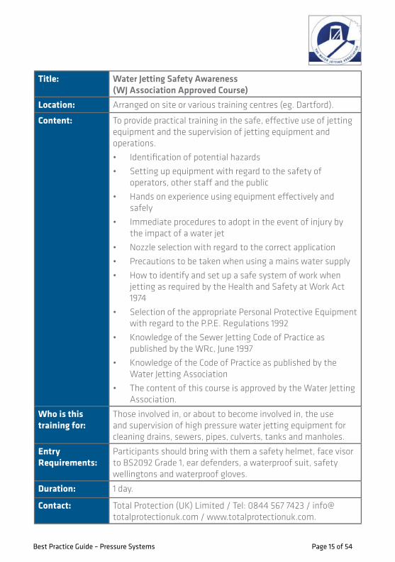
Title: Water Jetting Safety Awareness (WJ Association Approved Course)
Location: Arranged on site or various training centres (eg. Dartford).
Content: To provide practical training in the safe, eff ective use of jetting equipment and the supervision of jetting equipment and operations.
• Identifi cation of potential hazards
• Setting up equipment with regard to the safety of operators, other staff and the public
• Hands on experience using equipment eff ectively and safely
• Immediate procedures to adopt in the event of injury by the impact of a water jet
• Nozzle selection with regard to the correct application
• Precautions to be taken when using a mains water supply
• How to identify and set up a safe system of work when jetting as required by the Health and Safety at Work Act 1974
• Selection of the appropriate Personal Protective Equipment with regard to the P.P.E. Regulations 1992
• Knowledge of the Sewer Jetting Code of Practice as published by the WRc, June 1997
• Knowledge of the Code of Practice as published by the Water Jetting Association
• The content of this course is approved by the Water Jetting Association.
Who is thistraining for:
Those involved in, or about to become involved in, the use and supervision of high pressure water jetting equipment for cleaning drains, sewers, pipes, culverts, tanks and manholes.
EntryRequirements:
Participants should bring with them a safety helmet, face visor to BS2092 Grade 1, ear defenders, a waterproof suit, safety wellingtons and waterproof gloves.
Duration: 1 day.
Contact: Total Protection (UK) Limited / Tel: 0844 567 7423 / [email protected] / www.totalprotectionuk.com.

Best Practice Guide – Pressure Systems Page 16 of 54
Best PracticeSprayed Concrete LiningA logbook has been designed to record and monitor the progress of trainees during their formative / initial tenure on the project. The logbook will provide documented evidence of progress and achievement and includes:
• Personal Details
• Training & Qualifi cations
• Medicals and Occupational Health Monitoring
• SCL Operations
• Major Projects information.
On completion of SCL works the logbooks will be issued to the operatives as evidence of competence and experience. The Logbook will undoubtedly provide future employers with credible details of competence and performance. The logbook can also be used in the pursuit of construction NVQ’s.
CRL1-XRL-Z7-AAG-CR001-50001
üMajor Projects information.üMajor Projects information.

Best Practice Guide – Pressure Systems Page 17 of 54
Section C –Execution and Control

Best Practice Guide – Pressure Systems Page 18 of 54
Concrete Pumping andSpray Concrete LiningConcrete in pumps and/or pipelines is often under considerable pressure and failure of pipeline can result in signifi cant damage or injury. A concrete pump may give up to 85 bar pressure into the pipeline whereas a compressor will give 7 or 8 bar. Also the pump has a pulsing eff ect whereas the compressor will apply the pressure more evenly.
Pump Set-upThe concrete pumping area should be level, solid and free of obstructions, with careful attention paid to the positioning of the pumping equipment and any stabilising devices. In particular, the area should be:
• Clear of excavations, trenches or holes in the ground
• Clear of inadequately compacted or soft ground
• Clear of cellars, basements, pits or back-fi lled ground, unless stability is approved in writing by a qualifi ed engineer
• Clear of overhead power lines and fi xed electrical equipment
• Of a size enough to allow for safe operation
• Of a size enough to allow for the safe discharge from the concrete delivery trucks.
Where the pumping or pipeline set-up is for a longer duration, the isolation methods should be made more permanent. No person, other than those workers directly involved in the concrete
pumping operation, should be in the operational safety zone during concrete pumping.
Concrete Delivery areaThe concrete truck delivery area, including the area around the pump hopper, should be set up to ensure that:
• Workers are safe from other vehicles
• Adequate lighting is provided if pumping in non-daylight hours
• Appropriate signage is posted
• There is clear access for delivery trucks.
If multiple concrete deliveries are expected and on-site traffi c management is not provided, only one delivery truck should approach and discharge into the hopper at a time.
Keep clear when truck is reversing into position - ensure that you remain in the driver’s view.
Keep clear when truck is reversing into position - don’t stand between the truck and hopper.

Best Practice Guide – Pressure Systems Page 19 of 54
If a designated on-site traffic controller is provided, the following safety rules should be followed:
• All personnel connected with discharging from concrete trucks are to wear appropriate high-visibility safety vests
• All concrete delivery trucks must have operational reversing beepers.
All vehicles entering Crossrail are subject to requirements detailed in the Crossrail Vehicle Safety Kit (see Appendix F).
Receiving hopper and hopper guardingThe concrete pump should be positioned so the receiving hopper is at a height that allows a gravity flow of concrete from the pre-mix delivery trucks into the hopper.
The concrete pump should not be operated unless the hopper is equipped with a grille with a fitted and working safety interlock. The grille should:
• Be constructed of parallel or mesh bars
• Be designed to prevent access to the moving parts in the hopper
• Be designed so it requires a tool to be removed
• Not, under any circumstances, be used to stand on.
Operational safety zone Access to areas around the concrete pump and delivery pipeline should be restricted - the most appropriate method of isolating the area should
be used. The use of one or more of the following controls is recommended:
• Barricades
• Posts and safety mesh
• Posts and danger tape or flags
• Covered walkways
• The traffic controller and truck driver should be in positions which prevent them from being caught between the hopper and a reversing truck
• The traffic controller should be in a position visible to the reversing driver and where the hopper area can be observed
• Delivery drivers should ensure that their vehicles remain clear of the discharge area until signaled to reverse into position by the traffic controller.
Delivery Pipeline Set-upWhen installing a pipeline, ensure that:
• All specifications contained in BS EN 12001:2012, Section 5.3, are adhered to, particularly with regards to factors of safety when considering maximum delivery pressure
• The safe working pressure of the pipeline is equal to or greater than the rated maximum concrete pressure of all pumps to be used
• All pipes and pipeline components are identified and inspected before installation
• The pipeline is set up along the shortest possible route

Best Practice Guide – Pressure Systems Page 20 of 54
• The pipeline is set up using as few bends as is possible
• Hoses are only used to distribute the concrete at the end of a line, never used in the middle of a pipeline and/ or as an alternative to a bend
• A safety pin should be used to secure each and every coupling
• Each section of the pipeline is adequately supported and secured to the structure
• The pipeline should not be secured to a cranes or hoist towers, scaff olding or framework unless the bottom or footed bend (or bend cast into a ballast block) is used when the pipeline changes from horizontal to the vertical.
Pipe ClampsClamps connecting concrete piping need to be of the correct size, maintained
and rated at a working pressure greater than the maximum deliverypressure specifi ed above. All pipe clamps used on any pipeline system must be:
• Able to sustain the maximum concrete pressure applied to the pipeline by the pump
• Regularly inspected by a competent person for signs of wear or fatigue
• Immediately replaced if deformed or damaged.
Clamps should also be permanently marked with the manufacturer’s name (or trademark), and the maximum permissible operating pressure.
When using quick-release pipe clamps on fi xed lines (horizontal or vertical), ensure that:
• The pipe clamps used are able to sustain the maximum concrete pressure
• Locking pins are used and are engaged
• Pipe clamps are regularly inspected for signs of wear by a competent person
• Clamps showing any deformation or damage are replaced before pumping begins
• Safety pins are fi tted to all clamps. Clamps which do not allow for safety pins to be fi tted should be removed prior to pumping operations
Securely fi x the pipeline to avoid movement.

Best Practice Guide – Pressure Systems Page 21 of 54
• Clamps are locked as per the manufacturer’s instructions. Using a hammer or other means to force a clamp closed can cause unnecessary wear and result in failure of components.
All pipeline connections from the boom must be secured by safety chains or wire strops (whip-check devices) to prevent the pipeline falling to the ground if a clamp fails.
Pipeline MovementThe pipeline should be adequately secured to the building or structure, with attention given to the reaction forces generated where high pump pressures are involved. The mounting system should be designed to ensure the pipeline remains in place.
Support brackets in a vertical pipeline should be spaced no more than three meters apart. Expansion anchors of the high-load slip control type or other fi xing methods of at least the same structural strength should be used if fi xed to masonry.
The surging action of the pump should not cause excessive pipe movement. If required, additional anchor brackets or other suitable methods to restrict pipe movement should be used.
End-hoseThe rubber delivery end-hose should:
• Where connected to a boom, be secured by a safety chain, sling or other restraining device and not be longer than specifi ed by the pump manufacturer
• Be inspected for excessive wear or damage prior to being fi tted and on a regular basis
• Be single ended, in the case of the fi nal hose/ end placing hose.
If concrete pumping has stopped and the hose is maneuvered over a work or public area, the operator must use the hose shut off valve, if fi tted, to prevent concrete falling from the hose outlet. If such a valve is not fi tted, the boom should not be moved until all of the excess concrete has fallen from the boom and hose under gravity and the path the boom must travel is clear of people.
End-hose andreducer combinationIf the delivery end-hose is replaced by a hose and reducer combination, only those combinations assembled to the manufacturer’s instructions should be used, and:
• Locking pins are to be engaged on all quick-release pipe clamps in the assembly
• Each piece must be capable of withstanding the rated maximum pressure of the pump
• Each hanging piece is tethered by a safety cable, sling or chain

Best Practice Guide – Pressure Systems Page 22 of 54
• The combined weight of all pieces MUST NOT EXCEED manufacturer’s recommendations.
During Pumping OperationsTo safely operate any type of concrete pumping equipment, it is necessary to have enough workers to control the pumping operation. These workers need to be trained and experienced in conducting pumping operations.
The effective passing of directions from the hose-hand to the pump operator is essential for safe concrete pumping. The following examples may be used:
Effective communication between the hose-hand and the pump operator Is essential for safe concrete pumping. The following examples may be used:
• Non-verbal: a set of standard hand signals which cover all of the pump’s operational functions
• Verbal: standard operational phrases that may be delivered by a dedicated two-way radio system.
Regardless of the system used for communication, signals need to be agreed by the pump operator and hose-hand.
Pump operators must:
• Be competent, qualified and experienced
• Be familiar with the pump’s instruction manuals
• Be able to carry out daily maintenance tasks (greasing, topping up fluids, inspections etc.)
• Carry out a visual inspection of the pump and pipeline prior to each and every pour
• Be located at the pump controls or, if using a remote control, have a clear view of either the hose-hand or the hopper
• Follow the directions of the hose-hand
• If using hand signals and out of view of the hose-hand, be assisted by another worker to relay directions
• Report problems with the pump/ pipeline to the pumping supervisor without delay
• Stop pumping, in the event od a serious problem and do not re-commence pumping till the problems have been remedied
• Record daily inspections, defects and repairs in the logbook.
Pump operators must not:
• Leave the pump/ remote control box unattended whilst the pump is turned on
• Adjust the hydraulic pressure of the pump
• Pump concrete unless the hopper guard is in the closed position
• Stand or allow any other person to stand on the hopper grille or beneath the raised boom.
End-hose and reducer with safety slings.

Best Practice Guide – Pressure Systems Page 23 of 54
Hose-whipHose-whip occurs when pressure in the pipeline is released rapidly causing the end placing hoses to whip unmanageably. When a hose-whip occurs, the hose can strike those in the danger zone violently and can cause severe injury.
Controls which reduces likelihood of hose-whip• Ensure that the concrete pump
operator is competent, qualifi ed and experienced
• Ensure that the concreting operatives are competent, qualifi ed, experienced and aware of the risks and dangers associated with pressurized hoses
• Ensure good communication between the pump operator and the hose-man
• Use the correct quality and quality of grout when grouting up
• Reject any concrete that is out of specifi cation/un-pumpable especially that which is too lean, too stiff , or has been in the mixer for too long
• The hose should not be stretched if it cannot reach the pouring location
• Do not allow concrete to stand in the delivery pipeline for too long. If necessary, clean out the line, re-grout re-commence the pumping operation
• Do not allow the concrete level in the hopper to drop below the level
of the pumping cylinders—this can introduce air into the line
• Do not allow the hoses to kink
• Ensure that the delivery hoses are clean and undamaged before each and every pour.
Controls that can reduce the danger of injury due to hose-whip
• Use single ended hoses for the fi nal hose/ ending placing hose
• Ensure that all operatives are clear of the danger zone when the pipeline is being grouted up and at the beginning of a fresh load of concrete is being pumped through.
Other controls that can reduce the danger of injury while working with concrete delivery pipelines
• The length of the end hose of a placing boom must not exceed the manufacturers recommendation
• The hose-hand should stand on a fl at surface and not walls or underground structures edges
• The end hose of the boom pump should hang vertically, be guided and not forced
• Where possible, avoid working directly beneath the placing boom by guiding the hose from the side
• When the pump is stopped, close the hose shut off -valve and allow any extra concrete in the hose to fall before moving the boom
• Keep personnel/ members of the public clear of the concrete pump pour area
Best Practice Guide – Pressure Systems Page 24 of 54
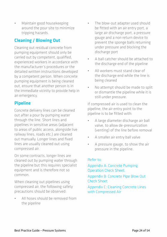
• Maintain good housekeeping around the pour site to minimize tripping hazards.
Cleaning / Blowing OutCleaning out residual concrete from pumping equipment should only be carried out by competent, qualified, experienced workers in accordance with the manufacturer’s procedures or the detailed written instructions developed by a competent person. When concrete pumping equipment is being cleaned out, ensure that another person is in the immediate vicinity to provide help in an emergency.
PipelineConcrete delivery lines can be cleaned out after a pour by pumping water through the line. Short lines and pipelines in sensitive areas (adjacent to areas of public access, alongside live railway lines, roads etc.) are cleaned out manually. Longer lines and fixed lines are usually cleaned out using compressed air.
On some contracts, longer lines are cleaned out by pumping water through the pipeline but this requires specialist equipment and is therefore not so common.
When cleaning out pipelines using compressed air, the following safety precautions should be observed:
• All hoses should be removed from the pipeline
• The blow-out adapter used should be fitted with an air entry port, a large air discharge port, a pressure gauge and a non return device to prevent the sponge balls returning under pressure and blocking the discharge port
• A ball catcher should be attached to the discharge end of the pipeline
• All workers must stand clear of the discharge end while the line is being cleaned
• No attempt should be made to split or dismantle the pipeline while it is still under pressure.
If compressed air is used to clean the pipeline, the air entry point to the pipeline is to be fitted with:
• A large diameter discharge air ball valve, to allow de-pressurization (venting) of the line before removal
• A smaller air entry ball valve
• A pressure gauge, to show the air pressure in the pipeline.
Refer to:
Appendix A: Concrete Pumping Operation Check Sheet.
Appendix B: Concrete Pipe Blow Out Check Sheet
Appendix C: Cleaning Concrete Lines with Compressed Air

Best Practice Guide – Pressure Systems Page 25 of 54
Best PracticeConcrete ‘Blow-out’ Chambers with Exclusion ZonesConcrete pipeline clean-out operations commonly involve the insertion of ball(s) that are driven through the line using compressed air. A ball catcher that allows the waste concrete to pass through it catches the sponge ball when the line is clean. Control of the volume of air in the line is required to prevent the potentially dangerous explosive releases of concrete and the cleaning balls into the ball catchers.
C512 has developed a bespoke chamber to control concrete blow-out during pipeline cleaning at Whitechapel. This chamber controls concrete blow-out and allows waste to fl ow out from its open base, in this way, the risk of injury from the release of concrete and/ or sponge balls is minimised.
After the operation, the chamber can be disconnected and lifted away. Then the waste concrete is then allowed to set, prior to broken up and removed from site.
Other designs in use on Crossrail are shown below:
üAfter the operation, the chamber can be üAfter the operation, the chamber can be disconnected and lifted away. Then the üdisconnected and lifted away. Then the
Chamber connected to pipeline for blow-out
Chamber has open bottom and is propped up to allow concrete to fl ow out
Inlet with ball catcher (4”)
5”
GO GO

**** The top photo shows the pipeline connected to the discharge chamber by placing a hose. All hoses should be removed from the line prior to blowing it out. setting up a cleaning line follows:
• Set up the main pumping line with a 1m pipe in the line close to the pump
• Remove the 1m pipe and replace it with a bend pointing towards the discharge chamber
• Set up the cleaning out line from the bend to the discharge chamber using all steel pipes and bend—as few bends as possible
• Connect the cleaning out line to the discharge chamber
• Secure the cleaning out line especially close to the discharge chamber
• When all of this is in place, remove the bend that diverts the pipeline to the cleaning out line and replace the 1m pipe
• It is ready to pump
• After the pumping operation has been completed, remove the 1m pipe and replace the bend to divert to the cleaning line
• Clean the line using compressed air back to the discharge chamber (This assumes cleaning back towards the pump).
Best Practice Guide – Pressure Systems Page 26 of 54

Best Practice Guide – Pressure Systems Page 27 of 54
Best PracticeProtection of concrete fl exi-hosesThe mechanical pressing-in of the hose by external forces is the most frequent cause for premature wearing of concrete pump hoses. This is what happens to the concrete pump hose if a heavy machine drives over it. Another frequent cause of damage is the hose rubbing against a sharp steel edge when fl exing during pumping concrete.
The concrete delivery hose contains a reinforcing layer of steel fi bres, similar to a car tyre. Once the external rubber skin of the hose has been damaged, moisture and oxygen come into contact with the reinforcing steel fabric which reduces the lifespan of the hose. To protect the delivery hose, the following is recommended:
• An additional layer protection. Whilst double-bagging is eff ective, it prevents easy inspection of the hose. An alternative is shown on the right which allows for visual inspection of the hose
• Protection of hoses from site traffi c. Some examples of how this might be done are shown below. The aim should be to prevent of contact between vehicle traffi c and the delivery hoses thus minimising risk of damage.
üThe concrete delivery hose contains a üThe concrete delivery hose contains a reinforcing layer of steel fi bres, similar üreinforcing layer of steel fi bres, similar
Flexi-hose preotection Double-bagging of hoses

Best Practice Guide – Pressure Systems Page 28 of 54
Pressure Wash OperationsPressure washers are used to clean equipment, materials and work areas on the job. Using such equipment often presents the perception that the associated work is low risk when in fact can cause serious injuries. Because the water used in jet washing operations is under high pressure, it moves with enough force to cause damage to the eyes or skin and contribute to other types of injuries.
Jet Wash Operations should only be undertaken following a Risk Assessment of all the tasks where it can be clearly demonstrated that there is no increase of risk to the operator and/or third parties.
Hazards
• The fast, strong spray can throw objects, striking and injuring others who are close by
• The strong spray from a pressure washer can cause serious wounds that might fi rst appear minor. Wounds that appear minor can cause a person to delay treatment, increasing risk of infection, disability or amputation
• Electric shock can occur if the pressure washer is not used properly and if safety instructions are not followed
• Jet washing can generate a large amount of noise. A Noise Risk Assessment is required to identify the actions required to comply with the Control of Noise at Work Regulations 2005.
Key Control Measures
• Pressure washers must only be used by suitably trained, competent and authorised persons
• Manufacturer’s safety information must be available and briefed to operatives
• Pressure washers should only be used for the purpose intended, not for cleaning PPE
• Residual pressure must always be released from all washer units after use
• Confi rm that lance safety catch is in position before starting and when putting down lance
• Start engine and, if adjustable, set desired pressure. Do not point lance at anyone, or yourself
• Hold lance with two hands to ensure control and maintain balance
• To avoid back blast of debris, pull trigger some distance back from
Ensure welfare facilities are provided to be used to wash / clean up after work activities
i

Best Practice Guide – Pressure Systems Page 29 of 54
point required and move it in slowly
• Set up exclusion zones or segregation of work area with suitable warning signs prominently displayed. Ensure other operatives are properly briefed on jet wash operations
• Avoid/eliminate potential distractions for jet wash operators in vicinity of works
• Take care with hoses to avoid trip hazards
• Refer to Page 30 for Jet Wash Risk Categories and recommended controls.
Refer to:
Appendix D: Jet Washing Operation Check Sheet example

Best Practice Guide – Pressure Systems Page 30 of 54
Risk Category Operating Pressure ControlsLow Up to 1500psi
(100bar)Standard PPE,Segregation of area,Awareness training, risk assessment briefing,Pre-use checks.
Medium 1501psi - 3000psi Same as above, with additional:Exclusion zone (“Authorised personnel only”),Safety Footwear (EN 345 or EN ISO 20345)Accredited one-day safety awareness course.
High 3001 - 20000 As above, with additional:Permit to work required,Exclusion zone(“No entry, permit to work area”),Specialist footwear, gloves and clothing.
Very high 20001psi + As above, with additional:Re-assessment of task and controls,Supervision (“ top-man” concept),Re-assessment of PPE,Specialist training/competence.
Jet Wash Risk Categories and Recommended Controls
Potential damage caused by jet washers decreases significantly the further way items are from nozzle. Newer jet washers have a safety feature: a safety cone around the nozzle which ensures a minimum distance is kept from the object being sprayed.
i

Best Practice Guide – Pressure Systems Page 31 of 54
Section D –Inspection and Maintenance

Best Practice Guide – Pressure Systems Page 32 of 54
Concrete PumpingProvision and Use of Work Equipment Regulations 1998 (PUWER) require that work equipment is maintained in an efficient state, in efficient working order in good repair and any machinery has a maintenance log, the log is kept up to date.
Concrete Pump Examination and testingCareful consideration should be given to the condition of the site where the test is to be conducted. It should be remembered that the recommendations provided in the operating instructions for the machine relate to operations within the safe working load and that more stringent requirements apply when loads are being applied for the purpose of testing.
A concrete-placer boom is not an item of lifting equipment as defined in the Lifting Operations and Lifting Equipment Regulations 1998. The examination of concrete-placing booms is specified in BS EN 12001.
Inspections should be completed by the concrete pump operator, or another competent person, on a weekly basis at least and by mechanical staff carrying out routine services. A written record of the inspections must be retained and be available at all times for examination.
A concrete-placing boom should be thoroughly examined:
• Every 500 operating hours or 20,000m3, whichever occurs first, but
• At least once a year and
• Following substantial alteration or repair.
The manufacturer of the machine or the competent person appointed to examine it may specify a more frequent examination period because of the machine’s age, its condition or its operating conditions, etc.
The thorough examination should be completed by a competent person who has the necessary knowledge and experience to carry out that duty.
In certain conditions, for example after substantial repairs to the boom, the competent person who examines the machine may specify the requirement for a load test to demonstrate that it is stable and / or structurally sound. Load testing of a concrete-placer boom should only be carried out under the direction and close supervision of a competent person.
A certificate of test and thorough examination should be issued following each thorough examination; a copy must be made available for viewing on the machine. The test certificate should state the maximum safe working load of the boom.
The test certificate should be endorsed with the information necessary to ensure that there is no ambiguity as to the configuration of the machine during the test. Certificates of test and thorough examination may be stored in any way appropriate to the owner of the machine, i.e. in paper format, electronically.
The safe working load of the machine, i.e. the maximum length of delivery hose full of concrete to be suspended

Best Practice Guide – Pressure Systems Page 33 of 54
from the boom, should be clearly marked on the machine and shown on the certifi cates of test and thorough examination.
Any other conditions, e.g. the deployment of stabilisers, must be noted on the certifi cate.
Following the thorough examination, a record of the examination should be retained for a period of at least three years to prove a regular inspection regime.
Refer to:
Appendix E: Examination Checklist for Concrete Pumps.
Concrete Pump MaintenanceAs with all machinery, good maintenance of a concrete pump is paramount to safety. Road safety and on-site safety must both be considered when planning a maintenance system. A good defect reporting and repair system is also vital.
The concrete pump operator should carry out regular inspections of the machine to ensure that it is fi t for use.
For Road vehicles, maintenance and inspection schedules should correspond to those required by the Vehicle and Operator Services Agency (VOSA).
Any defect aff ecting vehicle safety in respect of Road Traffi c Act requirements must be reported immediately to the maintenance department.
Any defect that, in the opinion of the concrete pump operator would aff ect the safe operation of the concrete-placer boom and its supporting
structure should be recorded on maintenance checklists and handed to a manager immediately.
Defects of a minor, non-safety related, nature should be recorded on maintenance checklists. They should be recorded weekly until the defects have been repaired.
A programme of servicing the chassis, the boom and its supporting structure and the concrete pump should be devised as a part of a preventative maintenance system. The period between services may be determined by the manufacturer or the owner of the machine and may be based on mileage, the number of hours worked or a period of time.
Pipeline ComponentsIn addition to daily/weekly checks of the pipeline components, additional measures can be taken to ensure potential failure is minimised.
It is important to measure the wall thickness of concrete delivery pipeline on a regular basis. Over time and with use, the wall thickness of a concrete delivery pipe will reduce, being worn away by the scouring eff ect of the pumped concrete. As the thickness of the pipe reduces, so does its capacity to contain pressure. If the pipes are allowed to wear excessively they can burst causing the pressurized concrete to explode out and potentially injure site personnel and members of the public. With testing and recording the thickness of pipeline walls at frequent intervals, excessive wear and potential failure of the pipeline can be avoided.

Best Practice Guide – Pressure Systems Page 34 of 54
Wall Thickness Testing
Wall thickness testing can be conducted by ultrasonic test instruments or other suitable method. All testing must be carried out by competent persons and test equipment calibrated according to the manufacturer’s requirements.
Any used components in storage should be tested before being returned to service.
Pipes must not be used if the wall thickness is less than that recommended by the pipe manufacturer for the maximum concrete pressure of the pump. The suppliers of pipes for concrete pumps should provide data on the minimum wall thickness for differing pump pressures. The safe minimum wall thickness of single wall pipe is dependent on the grade of steel, the pipe diameter and the maximum working concrete pressure that can be exerted by the pump.
Ultrasonic Testing
When using ultrasonic testers, it is essential to have the test instrument calibrated for the material to be tested before carrying out any tests. This can be achieved by using a piece of pipe material of a known thickness to calibrate the instrument and by following the manufacturer’s instructions. The test equipment should be maintained according to the manufacturer’s requirements, which may include regular factory calibration and replacement of worn transducers.
Pipeline Test Recording
To assist operators to detect erroneous measurements, cross referencing to previous wall thickness measurements during the testing process is essential. A suggested method of recording this information is to maintain a test sheet over the life of each component
This record of pipe component testing may include:
• Component identification number or mark
• Minimum allowable wall thickness
• Dates of tests
• Monthly measurement for each of the test points.
Non-Destructive Testing (NDT)
The presence of flaws in critical components (e.g. welding/joints in pipelines) may result in the integrity of such systems being compromised and increase the likelihood of failure.
Non-Destructive Testing (NDT) is the application of measurement techniques in order to identify damage and irregularities in materials.
If done well, NDT can provide useful information to assist in the management of plant safety. However, if inappropriate NDT is applied or NDT is not applied correctly, then the results are likely to give a false impression of the integrity and safety of the plant.
Hence, always seek professional advice with regards to the need and implementation of NDT.

Best Practice Guide – Pressure Systems Page 35 of 54Best Practice Guide – Pressure Systems Page 35 of 54
üBest PracticeHigh Pressure Hose Compensation GroutingFollowing a small number of cases where ‘ballooning’ of compensation grouting hoses occurred (Fig. 2), it was found that de-bonding of the inner skin and subsequent ‘kinking’ (that is not visible from the outside) has led to these failures. This is most likely
to occur at either end of the hose, but progressive de-bonding can allow the failure to progress along the length of the hose.
Following collaboration between Crossrail, the hose supplier and the manufacturer, a solution was implemented which resulted in a hose with a thicker and more integrated
reinforcing bond between the inner and outer skin (Fig. 3).
The benefi ts of this solution are:
• More rigid hose—less susceptible to damage by kinking and separation of inner hose.
• Larger bond surface between inner and outer hose reducing likelihood of separation.
• Stronger hose with a working pressure of 214bar.
Fig.2 Internal ‘ballooning’ failure
Fig.4 Old hose (left), and new hose (right) showing ‘castellated’ bonding with the outer skin

Best Practice Guide – Pressure Systems Page 36 of 54
Best PracticeSafetrak Electronic InspectionSite teams working at Whitechapel and Finsbury Circus identifi ed a need to improve the management of inspection regimes for pipework used to pump concrete.
The Safetrak Electronic Inspection system was implemented to manage and simplify equipment inspections and reporting. The system uses mobile computers, in conjunction with visual tags, to report on the location, usage and inspection status of pipework. This data is then uploaded to a central database.
The system has additional benefi ts in being able to provide asset registers, schedule reminders for inspections
and produce high-level summaries of inspection outcomes.
Assets can be tagged using a number of methods, including bar codes, serial numbering or Radio-frequency Identifi cation (RFID) tags, with tags being chosen in response to specifi c site conditions (ie. resilient to wear, water, dirt, chemicals etc.)
For further details email [email protected] or www.safetrak.com.
üand produce high-level summaries of üand produce high-level summaries of inspection outcomes.üinspection outcomes.

Page 37 of 54
Jet Washing / Pressure washers Regular maintenance is essential to ensure the safe operation of jet washers. This must be carried out in
accordance with the manufacturer’s instructions. Records must be kept of all maintenance and repair work carried out. Please refer to sample inspection and maintenance check list below.
Best Practice Guide —Pressure Systems
CRL1-‐XRL-‐O1-‐GUI-‐CRG03-‐50001, Rev 1 Page 36 of 50
Jet Washing / Pressure washers -‐ Page 1 of 2 Regular maintenance is essential to ensure the safe operation of jet washers. This must be carried out in accordance with the manufacturer's instructions. Records must be kept of all maintenance and repair work carried out. Please refer to sample inspection and maintenance check list below.
Section E: Inspection and Maintenance
Best Practice Guide – Pressure Systems

Best Practice Guide – Pressure Systems Page 38 of 54
Best Practice Guide —Pressure Systems
CRL1-‐XRL-‐O1-‐GUI-‐CRG03-‐50001, Rev 1 Page 37 of 50
Section E: Inspection and Maintenance

Best Practice Guide – Pressure Systems Page 39 of 54
Section E –Appendices
Best Practice Guide – Pressure Systems Page 40 of 54
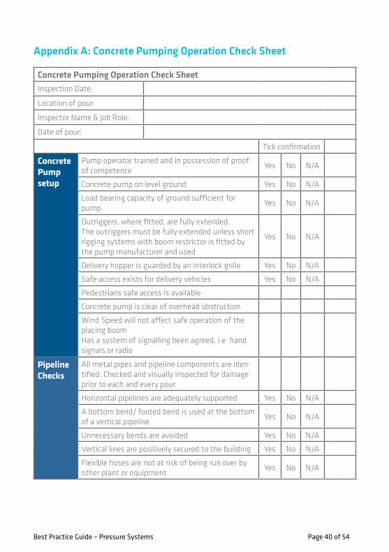
Appendix A: Concrete Pumping Operation Check Sheet
Concrete Pump setup
Pump operator trained and in possession of proof of competence
Yes No N/A
Concrete pump on level ground Yes No N/A
Load bearing capacity of ground sufficient for pump
Yes No N/A
Outriggers, where fitted, are fully extended. The outriggers must be fully extended unless short rigging systems with boom restrictor is fitted by the pump manufacturer and used
Yes No N/A
Delivery hopper is guarded by an interlock grille Yes No N/A
Safe access exists for delivery vehicles Yes No N/A
Pedestrians safe access is available
Concrete pump is clear of overhead obstruction
Wind Speed will not affect safe operation of the placing boomHas a system of signalling been agreed, i.e. hand signals or radio
Pipeline Checks
All metal pipes and pipeline components are iden-tified. Checked and visually inspected for damage prior to each and every pour.
Horizontal pipelines are adequately supported Yes No N/A
A bottom bend/ footed bend is used at the bottom of a vertical pipeline
Yes No N/A
Unnecessary bends are avoided Yes No N/A
Vertical lines are positively secured to the building Yes No N/A
Flexible hoses are not at risk of being run over by other plant or equipment
Yes No N/A
Concrete Pumping Operation Check SheetInspection Date:
Location of pour:
Inspector Name & Job Role:
Date of pour:
Tick confirmation

Best Practice Guide – Pressure Systems Page 41 of 54
Pipe Clamps & Brackets
The pipe clamps used are able to withstand the maximum concrete pressure applied to the pipeline by the pump.
Yes No N/A
Clamps are locked as per the manufacturer’s instructions
Yes No N/A
The locking pins are used and are engaged Yes No N/A
All pipe clamps are regularly inspected by a competent person for signs of wear and fatigue
Yes No N/A
Pipe clamps which show any deformation or damage are immediately replaced
Yes No N/A
Anchor brackets and tie-downs are used to adequately secure pipelines (2 brackets on the top face of slab and 1 bracket on vertical face. A competent person to assess whether additional brackets are required prior to pumping.
Yes No N/A
During the pour
Hopper grill with interlocked guard in place at all times
Ensure the pump is turned off when not in use
Ensure PPE is worn at all times. Long sleeves worn at all times.
Splashes of concrete onto skin should be washed off as soon as possible with soap and water.
Radio contact maintained between pump operator and other operatives at all times
Blowing Out / Cleaning
No pipeline connection or fitting should be disconnected unless it has been established that the pipeline is free of internal pressure.
No pipeline is to be left unattended unless it has been confirmed that the pipeline is free of internal pressure.
Only competent, qualified and experienced operatives are to clean out the pipeline
Yes No N/A
A ball catcher must be used to catch the sponge balls when the line is being cleaned out
Yes No N/A
All operatives must be briefed to keep clear from the discharge end while cleaning is in progress
Yes No N/A
Refer to the Concrete Pipe Blow Out Check Sheet in Appendix B for more detailed checks which need to be performed prior to every blowout operation

Best Practice Guide – Pressure Systems Page 42 of 54
Appendix B: Concrete Pipe Blow Out Check Sheet
Best Practice Guide —Pressure Systems
CRL1-‐XRL-‐O1-‐GUI-‐CRG03-‐50001, Rev 1 Page 41 of 50
Site: Date:
Time:
Initials of Competent Person:
Drive:
YES NO YES NO YES NO YES NO YES NO YES NO YES NO YES NO
Are all personnel aware that blow out is about to commence? Are there sufficient competent, qualified and experienced operatives to clean out the pipeline
Has the latest pipe line additions been checked? Has the blow out adapter been checked prior to the pour?
With blowing end -‐ is the cannon in good working order? Have the latest pipeline additions been checked prior to the pour?
Are ball catching arrangements in place?
Is there good communication between the blowing end and the receiving end? Is the pipeline adequately fixed and secure?
Appendix B: Concrete Pipe Blow Out Check Sheet

Best Practice Guide —Pressure Systems
CRL1-‐XRL-‐O1-‐GUI-‐CRG03-‐50001, Rev 1 Page 42 of 50
Is everyone in a safe location 30m from the catcher? Is there good communication between the blowing end, and ball follower and the receiving end?
Are all personnel aware that blow out is about to commence?
Is everyone in a safe location 30m from the catcher?
Appendix B: Concrete Pipe Blow Out Check Sheet
Best Practice Guide – Pressure Systems Page 43 of 53

Best Practice Guide – Pressure Systems Page 44 of 54
Appendix C: Briefi ng-Cleaning out Concrete Lines with Compressed Air
Briefi ng: Cleaning out Concrete Lines with Compressed AirAim: To provide instruction, training and awareness to allow you to clean out a concrete pipeline safely using compressed air following concrete pumping operations.
Briefi ng:
• On completion of a pour/advance, stop pumping, reverse the pump a minimum of three strokes to relieve the pressure in the line and then turn the pump off
• Check the pressure gauge on the pump is reading Zero
• Only when this is compete should you start dismantling the concrete line connected to the pump, ready for cleaning out.
The cleaning out activity on the surface must be controlled by the ‘senior’ pump operator on the shift.
• Disconnect the concrete pump from the pipeline
• Insert a wet hart sponge ball into the open end of the pipeline
• Re-check the blow out adapter to ensure that the valves can open and close properly and that the pressure gauge is undamaged
• The blow out adapter to the open end of the line with a good clean coupling seal and insert the safety pin
• Connect the airline, ensuring that the whip checks are in place
• Confi rm that a ball catcher has been installed to the discharge end of the pipeline and the pipeline is secured adequately
• Inform the person controlling the operation (this is the person with the radio at the pump outlet) that you are ready to blowout the lines
• Await instruction to proceed
• Ensure that the Blow Out Check Sheet has been completed
• Do not start until instructed to do so by the person controlling the operation underground.
Blow out pot adapter confi guration. This confi guration MUST be used
• Concrete Pipe Blow Out Check Sheet
2” Dump Valve
Pressure Gauge
3/4” or 1” Air supply Valve
Ensure any problems
are corrected BEFORE
the blowout operation

Best Practice Guide – Pressure Systems Page 45 of 54
• The person who is operating the blow out adapter should not leave the area for any reason whilst the adapter is connected to the line
• Ensure that there are visual communications at all times to back-up the radio system
• Before opening the air valve, ensure that the person controlling the blow-out underground has completed their checks and has moved everybody to a safe distance away from the blowout area
• Once confi rmation is received, open the air valve to introduce the air while monitoring the pressure increasing on the gauge. Maintain communication with the person controlling the blow-out underground and inform them of progress
• Do not leave the air supply valve on all the time—introduce air progressively for 15 to 20 sec intervals. The pressure as shown on the gauge will fall when air is turned off and the concrete moves ahead of the ball
• Repeat the above process until all residual concrete/ grout is cleaned from the line
• Pressure can be released at any time during the process by switching off the air supply valve and opening the dump valve
• Be aware that if the line blocks and the air pressure is vented via the dump valve, some concrete may also be expelled and so it is
important to ensure that the dump valve vents in a safe direction
• A second fl ush can be made when the line has been blown out by blowing two sponge balls with a slug of water between them
• Remember that concrete/ grout build up in the lines can cause problems and potential dangers on subsequent pours.
Fail-safe pressure release arrangement (example at the rear of the compressor)
Procedure for ensuring that air pressure on completion:
• Close the air supply valve on the blow out adapter when instructed to do so and/or when the red light is displayed
• Open the dump valve on the blow-out adapter to vent any pressure in the pipeline
• Check that the gauge is reading zero.
If there is any doubt as to whether or not the pressure in the line has been fully released, take the following steps:
• Close the air supply valve at the compressor/receiver
• Open the dump valve at the compressor/receiver
Pressure Gauge
Air Supply Valve
22” Dump Valve

Best Practice Guide – Pressure Systems Page 46 of 54
• Open the air supply valve on the blow out adaptor
• Check that both gauges are reading zero.
This now ensures that the air pressure is relieved in the concrete line and air supply pipe.
• If there is still any doubt, turn off the compressor and dump the air from the receiver
• Report any mechanical or equipment issues immediately to the Pit Boss or mechanical department
• When you are certain that there is no retained air pressure in the concrete line, the blow adapter can be uncoupled and removed from the end of the pipe
• The blow-out adapter must be cleaned thoroughly after each use to prevent any grout build up in valves and gauge and to ensure it is fit for use each time it is used.
Check
• Before removing the blow-out adapter at the end of blowing out, make sure the air supply valve is closed, the dump valve is open and the gauge is reading zero.
• If an unsafe condition arises during any stage of the operation you must stop immediately!
Release the pressure and do not restart until the unsafe condition has been remedied.
Finally
• During the cleaning out operation the concrete lines will have a considerable amount of stored energy!
Any uncontrolled release of this energy/pressure is a serious safety hazard!

Best Practice Guide – Pressure Systems Page 47 of 54
Best Practice Guide —Pressure Systems
CRL1-‐XRL-‐O1-‐GUI-‐CRG03-‐50001, Rev 1 Page 47 of 50
Date:
Location/Machine Type:
Inspector Name + Job Role:
Tick
confirmationü Comment
Yes No N/A
Is the work area clearly defined and are proper warning signs posted (exclusion zone if needed)?
Yes No N/A
Have precautions been taken to protect all electrical equipment affected?
Yes No N/A
Have all persons working in surrounding area been informed about the intention to carry out water jetting operations?
Yes No N/A
Are hoses and lines protected from accidental damage (vehicles, other operations in the area)?
Yes No N/A
Is there an adequate water supply? Yes No N/A
Have all personnel been provided with the appropriate PPE for this job?. Consider people in the immediate area too.
Yes No N/A
Have all personnel received the proper training for this job?
Yes No N/A
Have all personnel using the equipment been briefed and do they know how to use the equipment safely?
Yes No N/A
Is the location of emergency medical aid known? Yes No N/A
Are all fittings of the correct pressure rating? Yes No N/A
Are all hoses of the correct pressure rating? Yes No N/A
Are all fittings in good operating condition? Yes No N/A
Are all hoses in good operating condition? Yes No N/A
Are HAVs trigger times known and a schedule of rotation in place if trigger times are exceeded?
Yes No N/A
Appendix D: Jet Washing Operation Check Sheet
Best Practice Guide —Pressure Systems
CRL1-‐XRL-‐O1-‐GUI-‐CRG03-‐50001, Rev 1 Page 48 of 50
Important Notes:
Are good washing facilities available to wash hands before eating or drinking
Yes No N/A
Is the area clear of any obstacle which could cause slips, trips or falls?
Yes No N/A
Wear task specific PPE at all times
Wash hands before eating, drinking or smoking
Never use trigger-‐assist devices. Hand operation only.
Never try to clean PPE using pressure washers
Never point the jet at other people, regardless of distance
No line connection or fitting should be disconnected unless it has been established that the line is free of internal pressure.
No line is to be left unattended unless it has been confirmed that the line is free of internal pressure.
Appendix D: Jet Washing Operation Check Sheet
Appendix D: Jet Washing Operation Check Sheet

Best Practice Guide – Pressure Systems Page 48 of 54
Important Notes:
Wear task specifi c PPE at all times
Wash hands before eating, drinking or smoking
Never use trigger-assist devices. Hand operation only.
Never try to clean PPE using pressure washers
Never point the jet at other people, regardless of distance
No line connection or fi tting should be disconnected unless it has been established that the line is free of internal pressure.
No line is to be left unattended unless it has been confi rmed that the line is free of internal pressure.
üü

Best Practice Guide – Pressure Systems Page 49 of 54
A thorough examination should include as a minimum (where applicable):
• A visual inspection of all sections of the boom, its supporting structure, securing devices and stabilisers
• Non-destructive testing of the structure and welds when it is deemed necessary by the competent person
• The opening up of concealed or encased parts to the extent required by the competent person
• Measurement of backlash / play in the slewing system
• Measurement of wear in the slewing rack thrust pad
• Lift in the slewing ring
• The integrity of the slewing ring bolts
• Measurement of wear in pins and bushes at the boom joints
• A check on the security of boom pins
• The condition of boom pipe brackets
• The presence of security pins in pipe couplings on the boom pipeline
• The condition of the boom tip safety chain and its anchorage
• The correct operation of lock valves on the boom’s hydraulic rams
• The stabiliser locking system for both travelling and working
• The mounting fi xtures for the pump sub-frame and the boom pedestal to the chassis
• The workings of levers and switches on the remote control box(es)
• The condition of the remote control box lead
• The workings of manual control levers
• The operation of all emergency stop controls
• The clear marking of all controls
• The satisfactory operation of safety switches, e.g. slewing limits
• The operation of interlock systems, e.g. on the receiving hopper
• The integrity of the receiving hopper grille
• The guarding of the concrete pump cylinders’ fl ushing box
• The guarding of the machine’s prop-shaft
• The condition of the machine steps and walkway
• The condition of the washing-out adaptor and the sponge cleaning ball catching basket
• Working lights
• Appropriate warning signs
• The manufacturer’s identifi cation plates.
Appendix E: Examination Checklist for Concrete Pumps

Best Practice Guide – Pressure Systems Page 50 of 54
Appendix F: Crossrail Vehicle Safety Kit
22
DRIVER INDUCTION INFORMATION &CROSSRAIL VEHICLE SAFETY KIT
Supplementary Guide1
For further information contact:Crossrail Logistics Tra� c Coordination Centre
Tel: 020 3229 [email protected]
November 2015
Driver name:
Company:
Contact:
www.crossrail.co.uk
EA487
EA487 Cover Crossrail Safety Kit supplementary guide.indd 2 04/11/2015 15:56
MIRRORS AND VISUAL AIDS
Item Location
Class IV Mirror* Front nearside
Front nearside
Front of cab
In Cab (if applicable)
Near side window
Front mountedrear facing
Class V Mirror*
Class VI Mirror*
Fresnel Lensor camera system (below)
Side CameraSystem* (optional)
Rear view Mirror
12
Applies for:Small lorries 3.5 to 7.5 tonneü
Medium lorries >7.5 tonneü
Concrete mixer ü
2/3 Axle Rigid ü
Grab or skip lorryü
4 or multi axle tipperü
Articulated Low Loadersü
All other vehicles >7.5 tonne ü
EA487 Leaves Crossrail Safety Kit supplementary guide.indd 12 04/11/2015 15:54

Best Practice Guide – Pressure Systems Page 51 of 54
STICKERS, SIGNS AND DECALS
Item Location
Cyclist warning sign Rear nearside
Near side only
In the cab
In the cab
In the cab
In the cab
Rear/Sides
Pedestrian warning sign
Drugs & Alcohol warning
Maximum Passengers*
High visibiltity markings
Seat beltreminder
Daily inspection reminder
* Passenger carrying vehicles only e.g. minibus
DAILY INSPECTIONSMUST BE CARRIED OUT
IS:-
THE MAXIMUM LEGALCAPACITY OF THIS VEHICLE
14
Applies for:Small lorries 3.5 to 7.5 tonneü
Medium lorries >7.5 tonneü
Concrete mixer ü
2/3 Axle Rigid ü
Grab or skip lorryü
4 or multi axle tipperü
Articulated Low Loadersü
All other vehicles >7.5 tonneü
EA487 Leaves Crossrail Safety Kit supplementary guide.indd 14 04/11/2015 15:54
LIGHTING ANDCAB INTERIOR
Item Location
Stored on the vehicleWarning triangle
Stored on the vehicleSpare bulb kit
Stored on the vehicleFire extinguisher
Fitted to each seatSeat beltsto be worn
On any windowNo additional tinting
Front of the vehicleDaytime running lights(or sidelights on)
Top of cabAmber fl ashing
Beacon(All vehicles)
Rear fog lights Rear of vehicle
16
Applies for:Small lorries 3.5 to 7.5 tonneü
Medium lorries >7.5 tonneü
Concrete mixer ü
2/3 Axle Rigid ü
Grab or skip lorryü
4 or multi axle tipperü
Articulated Low Loadersü
All other vehicles >7.5 tonneü
EA487 Leaves Crossrail Safety Kit supplementary guide.indd 16 04/11/2015 15:54

Best Practice Guide – Pressure Systems Page 52 of 54
22
DRIVER INDUCTION INFORMATION &CROSSRAIL VEHICLE SAFETY KIT
Supplementary Guide1
For further information contact:Crossrail Logistics Tra� c Coordination Centre
Tel: 020 3229 [email protected]
November 2015
Driver name:
Company:
Contact:
www.crossrail.co.uk
EA487
EA487 Cover Crossrail Safety Kit supplementary guide.indd 2 04/11/2015 15:56
OUTSIDE THE VEHICLE
Item Location
Side scan detection kit
Nearside step or wheel arch area
Rear of the vehicleReversing alarm(can incorporate sensors and or a camera)
Orange Driver PPE
Hi Vis Clothing(See Principle Contractorsite rules)
Side under run guards Fitted both sides
Nearside of the vehicleExternal spoken warning alert*
18
Applies for:Small lorries 3.5 to 7.5 tonneü
Medium lorries >7.5 tonneü
Concrete mixer ü
2/3 Axle Rigid ü
Grab or skip lorryü
4 or multi axle tipperü
Articulated Low Loadersü
All other vehicles >7.5 tonneü
EA487 Leaves Crossrail Safety Kit supplementary guide.indd 18 04/11/2015 15:54

Best Practice Guide – Pressure Systems Page 53 of 54
Appendix G: References
References
BS EN 12001 Conveying, spraying and placing machines for concrete and mortar safety requirements.
Health and Safety at Work Act 1974
Lifting operations and Lifting Equipment Regulations 1998
Pressure Equipment Regulations 1999
Pressure Systems Safety Regulations 2000
Provision and use of Work Equipment Regulations 1998
Road Traffic Act
Vehicle and Operator Services Agency
BS
HASWA
LOLER
PER
PSSR
PUWER
VOSA
Abbreviations
PPE
RFID
SCL
TUCA
Personal Protective Equipment
Radio-Frequency Identification
Sprayed Concrete Lining
Tunnelling and Underground Construction Academy

Best Practice Guide – Pressure Systems Page 54 of 54
Further sources of informationAll of the documents listed in the ‘Reference documents’ section can be found at the following sites which are also extremely useful for information on all other aspects of site safety.
Numerals should be spelled out, not given as whole numbers: 121 is ‘one-two-one’, NOT ‘one hundred and twenty one’.
Phonetic alphabetA Alpha
B Bravo
C Charlie
D Delta
E Echo
F Foxtrot
G Golf
H Hotel
I India
J Juliet
K Kilo
L Lima
M Mike
N November
O Oscar
P Papa
Q Quebec
R Romeo
S Sierra
T Tango
U Uniform
V Victor
W Whiskey
X X-ray
Y Yankee
Z Zulu
Health and Safety Executive
UK Government legislation
Construction Industry Publications
Fire Protection Association
RISCAuthority
Loss Prevention Certification Board (LPCB)
Institution of Engineering & Technology (IET)
British Standards Institution (BSI)
www.hse.gov.uk
www.legislation.gov.uk
www.cip-books.com
www.thefpa.co.uk
www.riscauthority.co.uk
www.bre.co.uk
www.theiet.org
www.bsigroup.co.uk

Best Practice Guide – Pressure Systems Page 55 of 54
MOVINGHEALTH & SAFETY
FORWARD