best practices in ipv4 anycast routing - menog · best practices in ipv4 anycast routing gaurab raj...
TRANSCRIPT

Best Practices inIPv4 Anycast Routing
Gaurab Raj UpadhayaPacket Clearing House

What isn’t Anycast? Not a protocol, not a different version of
IP, nobody’s proprietary technology.
Doesn’t require any special capabilitiesin the servers, clients, or network.
Doesn’t break or confuse existinginfrastructure.
What is Anycast? Just a configuration methodology. Mentioned, although not described in detail,
in numerous RFCs since time immemorial. It’s been the basis for large-scale content-
distribution networks since at least 1995. It’s gradually taking over the core of the DNS
infrastructure, as well as much of theperiphery of the world wide web.

How Does Anycast Work? The basic idea is extremely simple: Multiple instances of a service share the
same IP address. The routing infrastructure directs any packet
to the topologically nearest instance of theservice.
What little complexity exists is in the optionaldetails.

Example
Client
Server Instance A
Server Instance B
Router 1
Router 3
Router 2
Router 4

Example
Client
Server Instance A
Server Instance B
Router 1
Router 3
Router 2
Router 4
10.0.0.1
10.0.0.1
192.168.0.1
192.168.0.2
Client Router 1
Example
Server Instance A
Server Instance BRouter 3
Router 2
Router 4
10.0.0.1
10.0.0.1
192.168.0.1
192.168.0.2
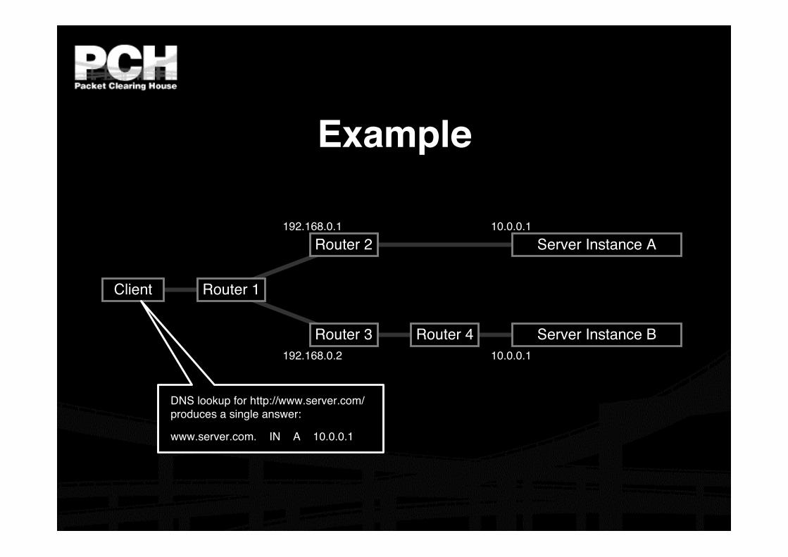
DNS lookup for http://www.server.com/produces a single answer:
www.server.com. IN A 10.0.0.1

Router 1
Example
Client
Server Instance A
Server Instance BRouter 3
Router 2
Router 4
10.0.0.1
10.0.0.1
192.168.0.1
192.168.0.2
Routing Table from Router 1:
Destination Mask Next-Hop Distance192.168.0.0 /29 127.0.0.1 010.0.0.1 /32 192.168.0.1 110.0.0.1 /32 192.168.0.2 2

Router 1
Example
Client
Server Instance A
Server Instance BRouter 3
Router 2
Router 4
10.0.0.1
10.0.0.1
192.168.0.1
192.168.0.2
Routing Table from Router 1:
Destination Mask Next-Hop Distance192.168.0.0 /29 127.0.0.1 010.0.0.1 /32 192.168.0.1 110.0.0.1 /32 192.168.0.2 2

Router 1
Example
Client
Server Instance A
Server Instance BRouter 3
Router 2
Router 4
10.0.0.1
10.0.0.1
192.168.0.1
192.168.0.2
Routing Table from Router 1:
Destination Mask Next-Hop Distance192.168.0.0 /29 127.0.0.1 010.0.0.1 /32 192.168.0.1 110.0.0.1 /32 192.168.0.2 2

Router 1
Example
Client Server
Router 3
Router 2
Router 4
10.0.0.1
192.168.0.1
192.168.0.2
Routing Table from Router 1:
Destination Mask Next-Hop Distance192.168.0.0 /29 127.0.0.1 010.0.0.1 /32 192.168.0.1 110.0.0.1 /32 192.168.0.2 2
What the routers think the topology looks like:

Building an Anycast Server Cluster Anycast can be used in building either
local server clusters, or global networks,or global networks of clusters,combining both scales.
F-root is a local anycast server cluster,for instance.

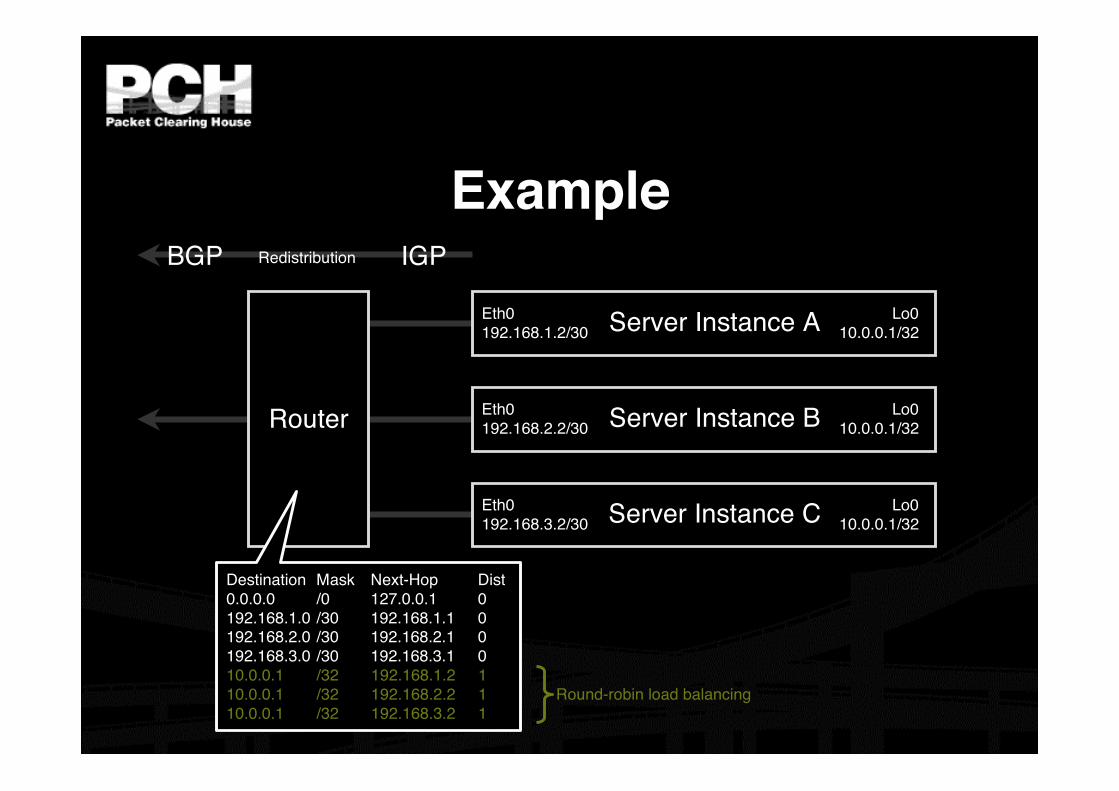
Building an Anycast Server Cluster Typically, a cluster of servers share a
common virtual interface attached totheir loopback devices, and speak anIGP routing protocol to an adjacentBGP-speaking border router.
The servers may or may not shareidentical content.

Example
Router
Eth0192.168.1.2/30
Lo010.0.0.1/32
Eth0192.168.2.2/30
Eth0192.168.3.2/30
Lo010.0.0.1/32
Lo010.0.0.1/32
Server Instance A
Server Instance B
Server Instance C
BGP IGPRedistribution

Router
Example
Eth0192.168.1.2/30
Lo010.0.0.1/32
Eth0192.168.2.2/30
Eth0192.168.3.2/30
Lo010.0.0.1/32
Lo010.0.0.1/32
Server Instance A
Server Instance B
Server Instance C
BGP IGPRedistribution
Destination Mask Next-Hop Dist0.0.0.0 /0 127.0.0.1 0192.168.1.0 /30 192.168.1.1 0192.168.2.0 /30 192.168.2.1 0192.168.3.0 /30 192.168.3.1 010.0.0.1 /32 192.168.1.2 110.0.0.1 /32 192.168.2.2 110.0.0.1 /32 192.168.3.2 1
Round-robin load balancing

Building a Global Network of Clusters
Once a cluster architecture has beenestablished, additional clusters can beadded to gain performance.
Load distribution, fail-over betweenclusters, and content synchronizationbecome the principal engineeringconcerns.

Example
Router 2
Serv
er In
stan
ce D
Serv
er In
stan
ce E
Serv
er In
stan
ce F
Router
3Router 1
Server
Instan
ce A
Server
Instan
ce B
Server
Instan
ce C
Server Instance G
Server Instance H
Server Instance I

Example
Router 2
Serv
er In
stan
ce D
Serv
er In
stan
ce E
Serv
er In
stan
ce F
Router
3Router 1
Server
Instan
ce A
Server
Instan
ce B
Server
Instan
ce C
Server Instance G
Server Instance H
Server Instance I
Region 1
Region 2
Region 3

Example
Router 2
Serv
er In
stan
ce D
Serv
er In
stan
ce E
Serv
er In
stan
ce F
Router
3Router 1
Server
Instan
ce A
Server
Instan
ce B
Server
Instan
ce C
Server Instance G
Server Instance H
Server Instance I
BGP Announcements
10.0.0.1 /32192.168.0.0 /22192.168.0.0 /16
10.0.0.1 /32192.168.8.0 /22192.168.0.0 /16
10.0.0.1 /32192.168.4.0 /22192.168.0.0 /16

Example
Router 2
Serv
er In
stan
ce D
Serv
er In
stan
ce E
Serv
er In
stan
ce F
Router
3Router 1
Server
Instan
ce A
Server
Instan
ce B
Server
Instan
ce C
Server Instance G
Server Instance H
Server Instance I
IGP 1 Announcements
10.0.0.1 /3210.0.0.1 /3210.0.0.1 /32
192.168.1.0 /30192.168.2.0 /30192.168.3.0 /30
10.0.0.1 /3210.0.0.1 /3210.0.0.1 /32
192.168.9.0 /30192.168.10.0 /30192.168.11.0 /30
10.0.0.1 /3210.0.0.1 /3210.0.0.1 /32
192.168.5.0 /30192.168.6.0 /30192.168.7.0 /30

Example
Router 2
Serv
er In
stan
ce D
Serv
er In
stan
ce E
Serv
er In
stan
ce F
Router
3Router 1
Server
Instan
ce A
Server
Instan
ce B
Server
Instan
ce C
Server Instance G
Server Instance H
Server Instance I
IGP 2 Announcements
10.0.0.1 /32192.168.1.0 /30192.168.2.0 /30192.168.3.0 /30
10.0.0.1 /32192.168.9.0 /30
192.168.10.0 /30192.168.11.0 /30
10.0.0.1 /32192.168.5.0 /30192.168.6.0 /30192.168.7.0 /30

Performance-Tuning Anycast Networks Server deployment in anycast networks is
always a tradeoff between absolute cost andefficiency.
The network will perform best if servers arewidely distributed, with higher density in andsurrounding high demand areas.
Lower initial cost sometimes leadsimplementers to compromise by deployingmore servers in existing locations, which isless efficient.

Caveats and Failure Modes DNS resolution fail-over
Long-lived connection-oriented flows
Identifying which server is giving anend-user trouble

DNS Resolution Fail-Over In the event of poor performance from a
server, DNS servers will fail over to the nextserver in a list.
If both servers are in fact hosted in the sameanycast cloud, the resolver will wind uptalking to the same instance again.
Best practices for anycast DNS serveroperations indicate a need for two separateoverlapping clouds of anycast servers.

Long-Lived Connection-Oriented Flows Long-lived flows, typically TCP file-transfers or interactive
logins, may occasionally be more stable than the underlyingInternet topology.
If the underlying topology changes sufficiently during the life ofan individual flow, packets could be redirected to a differentserver instance, which would not have proper TCP state, andwould reset the connection.
This is not a problem with web servers unless they’remaintaining stateful per-session information about end-users,rather than embedding it in URLs or cookies.
Web servers HTTP redirect to their unique address wheneverthey need to enter a stateful mode.
Limited operational data shows underlying instability to be onthe order of one flow per ten thousand per hour of duration.

Identifying Problematic Server Instances
Some protocols may not include an easyin-band method of identifying the serverwhich persists beyond the duration of theconnection.
Traceroute always identifies the currentserver instance, but end-users may noteven have traceroute.

A Security Ramification Anycast server clouds have the useful
property of sinking DOS attacks at theinstance nearest to the source of theattack, leaving all other instancesunaffected.
This is still of some utility even whenDOS sources are widely distributed.

PCH Anycast Service We provide anycast service for 14
ccTLDs and two gTLDs. At few selected locations, we provice
connectivity to the anycast instance ofthe i.root-servers.net
We have plans to anycast the SIPregistry of the INOC DBA(www.pch.net/inoc-dba).

PCH Anycast Network We look at a few things Uniformity Maximum Reachibility No recurring cost Easy way to manage with minimal staff and
attention Parallel operation of our route collection
system

Uniformity

Topology Redundant transit at every location Four global Transit nodes San Francisco and London are equivalent Ashburn and Hongkong are equivalent
Tunnel mesh Dual Tunnel Hub in different continent for
management Redundant private hubs

Current (as of earlier this year)anycast Footprint
SeoulSeoul
Hong KongHong Kong
SingaporeSingapore
KatmanduKatmandu
DhakaDhaka
PerthPerth
SydneySydney
WellingtonWellington
AucklandAucklandJohannesburgJohannesburg
MaputoMaputo
DarDar es es SalaamSalaamNairobiNairobi
KampalaKampala
KinshasaKinshasa
IbadanIbadan
StockholmStockholm
ViennaViennaLondonLondonNew YorkNew York
Washington D.C.Washington D.C.MiamiMiamiSan DiegoSan Diego
SeattleSeattle
Palo AltoPalo AltoLos AngelesLos Angeles
San FranciscoSan Francisco

New Sites in the Pipeline
São PauloSão Paulo Port LouisPort Louis
MoscowMoscow
ColomboColombo
HanoiHanoi
Ho ChiHo Chi Minh Minh CityCity
TokyoTokyoKabulKabul

How we do it. We have two routers with different ASN connected to
the IX. We run multiple peering sessions with eachpeer.
Transit is generally provided through a separate link. We have a /23 assigned for our own anycasting The Routers announce the /23 as well as
management address at each location. Global Nodesannounce all networks.

What on the host ? Use rsync to sync the anycast nodes
Using AXFR/IXFR is fine with DNS, but we alsoneed to sync other stuff, so we use rsync everyhour.
Run quagga on our servers Runs iBGP with the routers. If the host goes down,
the iBGP sessions goes down, thus the routerwithdraws the network from the peers.
For the i.root-servers.net and the .biz servers,we run BGP with their blades.

What does all of these do fornetworks?
Distributing DNS servers or other static systemacross the network Inject a /32 for your DNS servers into the IGP and then put
multiple servers everywhere. The customers don’t need tochange DNS server IP each time they change locations
Sink DoS traffic to the closest node Netflow collection to the closest node Standardization of router and system configs.

Questions ?

Thank YouGaurab Raj Upadhaya
Peering and Network GroupPacket Clearing House
With acknowledgements to Bill Woodcock.The anycast tutorial can be found at
http:// www.pch.net / resources / tutorials / anycast