best practices manual 2nd edition 2016
TRANSCRIPT

BEST PRACTICES mAnuAl 2nd EdITIon2016A guidebook of field-tested construction details from the maritime Pacific NW.


i
INTRODUCTION
This Best Practices Manual is the product of Hammer & Hand’s ongoing work to document and internally codify
our standard operating procedures for construction practice. It has evolved into a guidebook of field-tested construction
details, many shaped by Hammer & Hand’s experience in high performance passive building. We expect the information
contained herein to grow, deepen, and evolve as it is informed by experience in the field and collaboration with the many
professionals with whom we are honored to work.
The first edition of the manual focused on ensuring proper moisture management in buildings, with particular emphasis
on our fluid-applied flashing approach to window and door installation, our preferred method for constructing
ventilated rain screens, our approaches to new basement construction and basement retrofits, as well as other details.
This edition includes those details, some of which have been refined, and adds sections about walls and roof assemblies,
detailing key strategies for controlling heat, air, and moisture.
To our employees: this manual is a guide, not gospel. You will routinely encounter realities in the field that do not match
“laboratory conditions,” and will need to adapt accordingly. What needs to remain constant is that fieldwork is guided
by sound building science, so be sure to consult with our in-house building science experts when adapting these details.
Also, manufacturer’s installation instructions and architect’s construction drawings and specifications always take
precedence over the details in this Best Practices Manual. Any discrepancies with this manual should trigger discussion
with the architect about alternative approaches to their detailing. However, any alterations to architect’s plans must
be approved by the architect and such approval memorialized in an SK, ASI, RFI or other contractual method.
To our industry colleagues: we share this manual in the spirit of collaboration. These details have been developed
through extensive in-the-dirt experience and informed by building science training and practice. From our experience in
the maritime Pacific Northwest, they combine durability, performance, and constructability. That said, we know there
are several ways to solve any building problem, and also respect that responsibility for the design of construction details
ultimately rests with the architect. The details in this manual can be a starting point for discussion as we collaborate with
you on a project. And you are free to draw upon them in any project you are designing, regardless of whether we’re
involved. This manual is also available online at: http://hammerandhand.com/bpm.
Thank you.
DIsClaImeR
Hammer And Hand, Inc. (H&H) has compiled this publication with care, but makes no warranty of any kind, expressed or
implied, with regard to the information contained herein. The information, services, products, and materials contained in
this manual, including but not limited to text, graphics, artwork, photographs, illustrations, and data, are provided on an
“as is” and “as available” basis without warranty or other obligation of any kind. All risk of use lies with the user.
The information presented in this manual must be used with care by professionals who understand the implications of
what they are doing. If professional advice or other expert assistance is required, the services of a competent profes-
sional shall be sought. The author and publisher shall not be liable in the event of incidental or consequential damages in
connection with, or arising from, the use of the information contained within this H&H manual.


1 FLASHING 1
1.1 Flashing 2
1.2 Head Flashing 5
2 SeALANT JoINTS 9
2.1 Sealant Joint Design 10
3 WINDoWS & DooRS 11
Introduction 12
3.1 New Window Installation 13
3.2 Window Retrofit 19
3.3 Window Buck in a Masonry Wall 22
3.4 Door Installation 25
4 RAIN ScReeNS 31
Introduction 32
4.1 Top of Wall 33
4.2 Top of Window 36
4.3 Bottom of Window 40
4.4 Bottom of Wall 43
4.5 Gable end 46
4.6 Horizontal Rain Screen
Furring for Vertical Siding 48
5 eNVeLoPeS 53
Introduction 54
5.1 Wall Penetrations 55
5.2 Air Sealing 61
5.3 Insulation 66
5.4 exterior continuous
Insulation (cI) at Walls 71
5.5 Wall Assembly example 74
6 RooFS 77
6.1 Kick-out Flashing 78
6.2 Vented and Unvented
Roof Assemblies 83
6.3 Parapet Walls 85
6.4 Flat Roof Assemblies 91
7 BASeMeNTS 93
7.1 Basement, New construction 94
7.2 capillary Break 97
7.3 Sub Slab Vapor/Soil Barrier 98
7.4 Basement Retrofit 99
8 cRAWLSPAceS 103
8.1 General Guidelines 104
8.2 New construction: conditioned
with Insulated Slab 105
8.3 Retrofit option 1: conditioned
with Soil Barrier 106
8.4 Retrofit option 2: Vented
with Floor encapsulation 107
9 STRUcTURe 109
9.1 Deck Ledgers 110
9.2 Pocket Door Framing 114
9.3 Stair Framing 115
ABBReVIATIoN ReFeReNceS 116
AcKNoWLeDGeMeNTS 117
iii
This creative commons license allows for redistribution, commercial and non-commercial, as long as
it is passed along unchanged and in whole, with credit to Hammer & Hand. If any piece is shared online,
it is required to credit Hammer & Hand and link to www.hammerandhand.com.
CONTeNTs


1
1
FlasHING
1
1.1 Flashing
1.2 Head Flashing
BEST PRACTICE dETAIlS STEP-BY-STEPFLASHING
Note to Hammer & Hand field staff:
Manufacturer’s installation instructions and architect’s construction drawings and specifications always take
precedence over the details in this Best Practices Manual. Any discrepancies with this manual should trigger discussion
with the architect about alternative approaches to their detailing. However, any alterations to architect’s plans must be
approved by the architect and such approval memorialized in an SK, ASI, RFI or other contractual method.

1
2
FLASHING
1.1 FLASHING
“The fundamental principle of water management is to shed water by layering materials in such a way that water
is directed downwards and outwards out of the building or away from the building. The key to this fundamental
principle is drainage. The most elegant expression of this concept is flashing. Flashings are the most underrated
building enclosure component and arguably the most important.” -Joe Lstiburek
B. Flashing: Where to Install It
Flashings should be installed:
1. At all horizontal joints between different exterior
finishes unless the upper finish overlaps
the lower finish.
2. At every offset in cladding, changes in cladding
substrate, and at all penetrations (horizontal
transitions between siding, stone, brick, tile,
or stucco).
3. Where stresses can be concentrated
(such as at the rim joist/foundation joint).
4. Where drainage is compromised
(such as a change from wall cladding to parging).
5. The top and bottom of windows, doors, and all
penetrations (vents, lights, hose bibs, electrical
outlets, electrical meters, etc).
4”
Trim Depth + 1/4”
1/2” min
110º
~3/8”
PReFINISHeD GALVANIZeD STeeL24 GAUGe MINIMUM
FIGURe 1.1 A
a. Flashing Dimensions
1/2” MIN
- 3/8”
TRIM DePTH +1/4”
110°

3
1
FLASHING
1
FIGURe 1.1 B
1/4” Gap between �ashing and siding
FIGURe 1.1 c
C. Flashing: Important Points
1. Building paper lapping: Install in a shingled fashion
with the upper sheet always overlapping the lower
sheet by a minimum of 4”. This and the down and
out principle shown below.
2. NeVeR rely on any self-adhering membranes
(tape, peel and stick) in lieu of properly shingled
laps or fluid applied flashing.
3. Minimum flashing slope: 20 degrees.
1/4” GAP BeTWeeN FLASHING AND SIDING
4. Leave a 1/4” minimum gap between cladding
termination and sloped metal drip flashings, shown
in figure 1.1 c (this detail can also apply to other
flashing details such as: belly bands, exterior
penetrations, etc.).
5. If above average shrinkage or differential movement
is expected (wood to masonry transition
or multi-story building) the minimum gap between
flashing and the cladding should be increased to
1/2”.
4” Min. Overlap
Down
Out
DoWN
oUT
4” MIN. oVeRLAP

1
4
FLASHING
D. Drip edges
Flashing with a hemmed drip-edge breaks water surface tension and prevents water from running along
the underside of the flashing and back into the wall.
FIGURe 1.1 D
Important Note:
Flashing penetrations: Penetrations (pipes, cables, refrigerant lines, vents, etc.) must be flashed before the cladding
is installed. It is nearly impossible to properly flash a penetration without removing the cladding around the penetration.
Be sure to have a plan for all flashings through the building enclosure prior to cladding the building.

5
1
FLASHING
1
Head Flashing Specifications:
About Head Flashing:
In high exposure locations, head flashing should incorporate an end dam to prevent water from running
off the end of the flashing. At this location the cladding may need to be cut to fit around the projection of the end dam.
1.2 HeAD FLASHING
4”
Trim Depth + 1/4”
1/2” min
110º
≈3/8”
Prefinished Galvanized Steel24 Gauge MinimumPReFINISHeD GALVANIZeD STeeL 24 GAUGe MINIMUM
TRIM DePTH + 1/4”
1/2” MIN.
~ 3/8”
4”
1
6
FLASHING
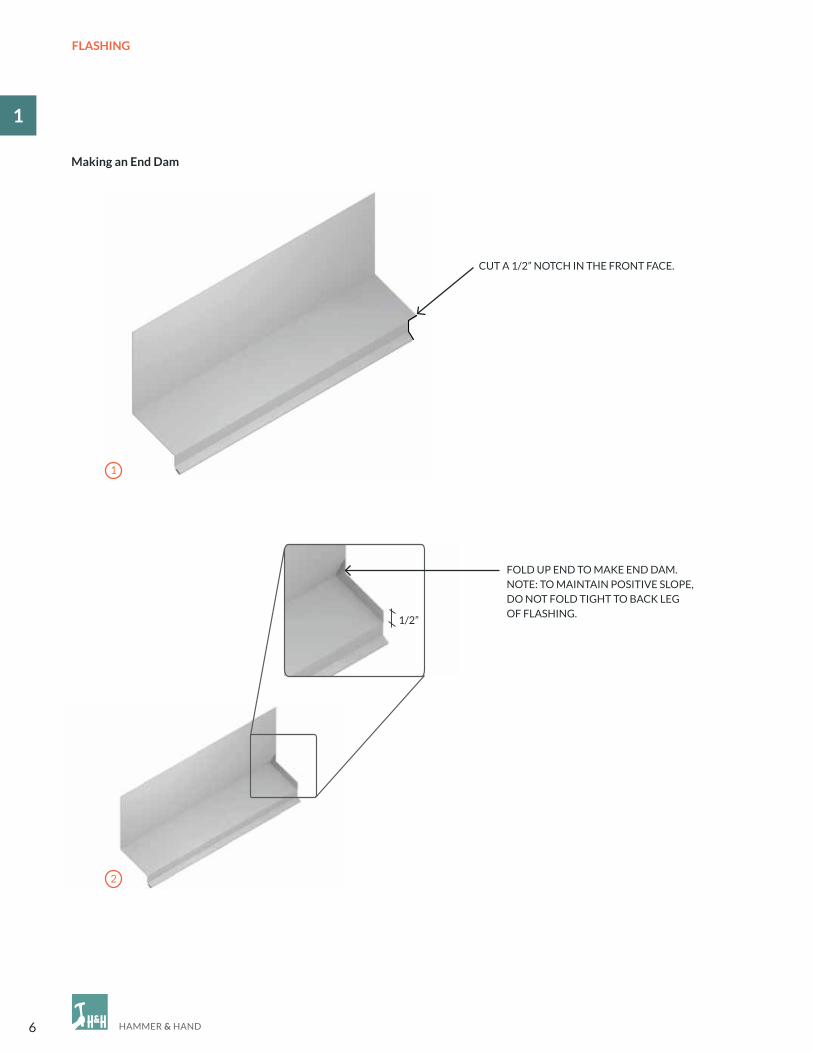
cUT A 1/2” NoTcH IN THe FRoNT FAce.
1/2”
FoLD UP eND To MAKe eND DAM.NoTe: To MAINTAIN PoSITIVe SLoPe, Do NoT FoLD TIGHT To BAcK LeG oF FLASHING.
2
1
making an end Dam

7
1
FLASHING
1
FoRM A SAFeTY eDGe BY FoLDING DoWN oUTeR coRNeR.
3

1
8
FlasHING
• clip flashing back to window casing at bends
to create flaps for bending.
• Trim hemmed edge so it ends at the edge
of the window casing and does not extend
with the other tabs.
making Folded Down ends
• Fold down the horizontal part of flashing over
the side of the window casing.
• Solder head flashing at the ends
to make watertight.
BAcK LeG oF FLASHING SHoULD exTeND PAST HeAD cASING.
• Fold front tab back against side of casing.
3
2
1

9
sealaNT JOINTs
12
Introduction
2.1 Sealant Joint design
BEST PRACTICE dETAIlS STEP-BY-STEPSeALANT JoINTS
Note to Hammer & Hand field staff:
Manufacturer’s installation instructions and architect’s construction drawings and specifications always take
precedence over the details in this Best Practices Manual. Any discrepancies with this manual should trigger discussion
with the architect about alternative approaches to their detailing. However, any alterations to architect’s plans must be
approved by the architect and such approval memorialized in an SK, ASI, RFI or other contractual method.

10
SEALANT JOINTS
2
2.1 SeALANT JoINT DeSIGN
HoT WeATHeR cAUSeS SUBSTRATeS To exPAND, coMPReSSING THe JoINT.
coLD WeATHeR cAUSeS SUBSTRATeS To SHRINK, exPANDING THe JoINT.
• Joint Rule of Thumb: Sealant should be hourglass-
shaped and width should be twice depth (shown
in diagram).
• Backer rod diameter should be 25% larger than
the joint to be filled.
• Joint size should be 4x the expected amount
of movement (usually about 1/2” of space
on all sides of the window casement).
• Ideal joints are within a range of 1/4” at minimum
and 1/2” at maximum. Joints outside this range
require special design and installation.
• Always use the right tool: sealant is not caulk
and should never be tooled with a finger
(saliva interferes with bond).
• Substrates need to be clean, dry, and properly
prepared (primer if necessary).
• When dealing with thermally sensitive materials,
apply sealant under average temperature conditions
because joints expand and contract with changes
in temperature (see below).
Joint expansion and Compression
While the humble sealant joint may be uncelebrated, it is vital to building durability and longevity. Proper installation is
key to sealant joint integrity and function throughout a life of expansion and compression, wetting and drying, exposure,
and temperature fluctuation.
Note: Because sealants are just as good at keeping moisture in as they are in keeping it out, placing a bead of caulk in the
wrong location can result in moisture accumulation, mold and rot, envelope failure, and hundreds of thousands of dollars
in repair and remediation. If we know anything, we know that building envelopes will get wet – the question is, “where
will the water go?” Make sure you know the answer throughout construction, especially as you seal joints.
Width= 2 x Depth
DepthSealant
Backer Rod
WIDTH = 2 x DePTH
DePTHSeALANT
BAcKeR RoD

11
WINDOWS & DOORS
13
3.1 new Window Installation
3.2 Window Retrofit
3.3 Window Buck in a masonry Wall
3.4 door Installation
BEST PRACTICE dETAIlS STEP-BY-STEPWINDoWS & DooRS
Note to Hammer & Hand field staff:
Manufacturer’s installation instructions and architect’s construction drawings and specifications always take
precedence over the details in this Best Practices Manual. Any discrepancies with this manual should trigger discussion
with the architect about alternative approaches to their detailing. However, any alterations to architect’s plans must be
approved by the architect and such approval memorialized in an SK, ASI, RFI or other contractual method.

12
WINDOWS & DOORS
3
INTRoDUcTIoN To WINDoWS & DooRS
Rough openings are inherently dangerous spots on a building, like big holes in the hull of a ship. So it is vital to flash them
well and install windows and doors in an airtight manner that also manages moisture and thermal transfer. our
preferred method outlined here – fluid applied flashing – is guided by three truths:
1. Windows will leak. Not all of them, but over a whole building, it’s a matter of when, not if. We therefore need to detail
our rough openings so that when a window leaks, the water can drain out harmlessly. (Note: this is why we place
the air seal at the inside edge of the window, or door, assembly, to allow water to drain outboard of that seal.)
2. Origami is hard. The conventional way of flashing a window with papers and tapes depends on dozens of steps being
performed perfectly every time: careful folds and precise manipulation of less-than-forgiving materials in the field.
Simple mistakes, like reverse lapping, can be catastrophic to the assembly but can be covered up by subsequent layers
of material, so checking work thoroughly can be impossible. Now multiply these risks by the number of windows
on a building and you will understand why window installations can be anxiety inducing. Fluid applied flashing,
by contrast, is more simple to apply in a few steps, and quality control is easy; if the applied layer is thick enough
to be opaque, then it is thick enough to do its job. As long as proper materials are used, one fluid applied layer integrates
seamlessly with the next, eliminating the risk of reverse lapping (except where the fluid applied system integrates with
building paper). And unlike tapes that often require dry conditions for proper adhesion, many fluid applied flashing
products are actually easier to apply on wet materials, a very common situation on Pacific Northwest construction sites.
We can all sleep well at night.
3. Flashings should be vapor permeable. If flashings are not vapor permeable then moisture can build up behind them
and cause rot. The high vapor permeability of fluid applied flashing ensures that construction moisture and seasonal
water vapor migrating through the wall assembly does not accumulate behind the flashing and can readily dry.

13
WINDOWS & DOORS
13
3.1 NeW WINDoW INSTALLATIoN
• Router or sand the rough opening (Ro) to make
clean edges for applying fluid flashing.
• Pass over outer edges with sand paper
to get rid of any inconsistencies.
• Ros should be 1” larger than window dimensions,
both width and height. If space requirements
are not met, square or fix before continuing.
• Slope the sill using beveled siding or a wedge.
• Apply Joint & Seam Filler to all joints and voids larger
than 1/4” that are to be covered in FastFlash.
• ensure that all nails are set, apply pink Joint & Seam
Filler and tool into place.
• Apply FastFlash to sill, extending 9” out from
the Ro to either side.
• Take care not to FastFlash too far below
the Ro because the transition strip will become
embedded on contact and the water-resistive barrier
(WRB) will not be able to slip underneath.
• Recommended: spread FastFlash 2” down from
the bottom of the Ro.
2
3
1
14
WINDOWS & DOORS
3
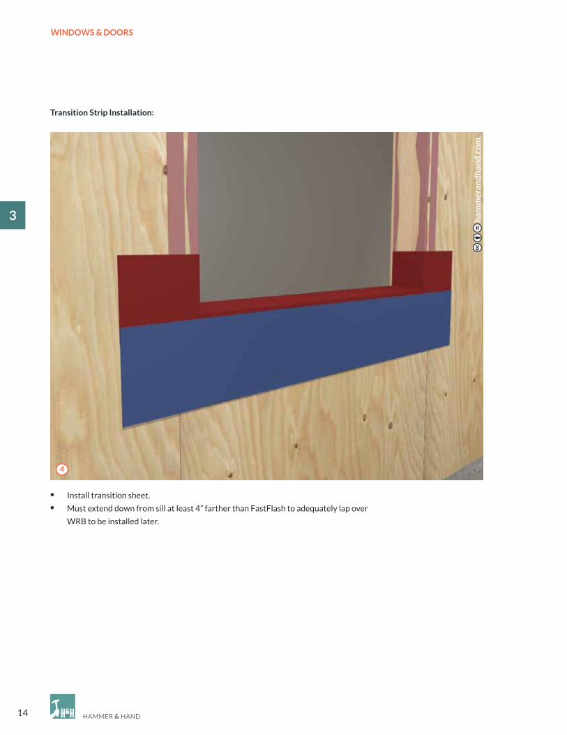
• Install transition sheet.
• Must extend down from sill at least 4” farther than FastFlash to adequately lap over
WRB to be installed later.
Transition strip Installation:
4

15
WINDOWS & DOORS
13
• Insert window in Ro and fasten according
to manufacturer’s specifications.
• Apply Joint & Seam Filler to head and side flanges
and tool. For special cases where flanges must
be taped for warranty purposes seek additional
guidance for suitable alternative.
• NeVeR seal the sill.
• FastFlash around the rest of the Ro and tool over
top edges of transition strip to avoid reverse lapping.
• Provide complete, level support for windows, where
framing allows, by installing plastic or decay-resistant
wood shims.
• Use horseshoe shims to hold window flange
off of the sheathing so water can drain
if the window fails.
• RecoMMeNDeD: 1/16 or 1/8” horseshoe shims.
5 6
7 8
16
WINDOWS & DOORS
3
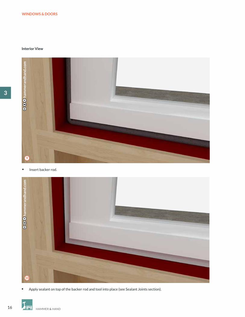
• Insert backer rod.
• Apply sealant on top of the backer rod and tool into place (see Sealant Joints section).
Interior View
9
10

17
WINDOWS & DOORS
13
• Slide WRB under transition strip. • Apply WRB around window.
• complete WRB face, lapped.
• Make sure WRB is lapped over the built-in flashing
at the top of the window and taped.
• Install trim.
Note: See alternate rain screen head flashing detail in section 4.2 Top of Window.
11 12
13 14

18
WINDOWS & DOORS
3
• cut a slit in the WRB, fold up, and use tape to hold
the flap out of the way while the head flashing
is installed.
• Attach head flashing.
• Apply Joint & Seam Filler to the top of the back
leg of the head flashing.
• Tool Joint & Seam Filler into place.
• Fold WRB flap back down and tape the slit to prevent
water intrusion.
• Attach siding.
• There should be a 1/4” gap between the bottom of
the sill trim and the siding underneath
for expansion and contraction.
1/4” MIN. GAP
15 16
17 18

19
WINDOWS & DOORS
13
3.2 WINDoW ReTRoFIT
• carefully remove existing trim and try to salvage
for use after new window is installed.
• existing conditions to be retrofitted.
• Remove existing window.
• Adjust framing as necessary to make opening square
and allow for 1/2” of space around window frame.
• If adding a sloped sill, be sure to account
for the height of the sloped sill in addition
to the 1/2” of space on each side
of the window casing.
1 2
3
• Apply Joint & Seam Filler to corners, intersections,
and edges of opening.
• Tool into place.
4

20
WINDOWS & DOORS
3
• Use shims to leave a space between the bottom
flange and building frame to allow drainage
in case of window failure.
• 1/16” to 1/8” horseshoe shims are recommended.
• Lift up any existing building paper and continue
FastFlash out as far as possible.
• Apply FastFlash around inside of opening
and extend out as far as possible from opening
on face of sheathing.
• When possible, bring FastFlash out over
the top of siding for continuous lapping
(shown with window installed).
5 6
7 8

21
WINDOWS & DOORS
13
• complete the window retrofit by fitting trim
and caulking around edges where the trim meets
the siding on the sides, but NeVeR the bottom.
• Kerf bottom of sill trim with a 3/16” drip edge.
• Install window in Ro and fasten per manufacturer
specifications.
• Bead and tool Joint & Seam Filler along top window
flange to prevent water intrusion.
• optional (pictured): Apply Joint & Seam Filler
to jambs as well, but NeVeR to sill.
• Install head flashing to protect the trim.
9 10
1/4” MIN. GAP
11 12

22
WINDOWS & DOORS
3
3.3 WINDoW BUcK IN A MASoNRY WALL
• Rough opening.
• Apply Joint & Seam Filler to the opening
where the buck will be installed.
• Screw window buck into masonry
opening.
2
1
3

23
WINDOWS & DOORS
13
• Use Joint & Seam Filler to seal around
the installed window buck.
• Also apply to corners and seams where
the pieces of the buck come together.
• FastFlash the buck from the inside edge
of the sill to the building face.
• extend FastFlash out from opening
as wide as the trim to be installed.
• Install window in FastFlashed Ro.
4
5
6

24
WINDOWS & DOORS
3
• Insert properly sized backer rod, taking
care not to puncture or damage it.
• AirDam over the backer rod and tool
the joint.
Interior View
7
8
25
WINDOWS & DOORS
13
3.4 DooR INSTALLATIoN
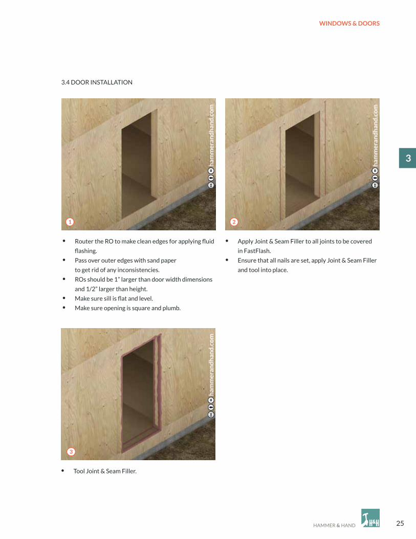
• Router the Ro to make clean edges for applying fluid
flashing.
• Pass over outer edges with sand paper
to get rid of any inconsistencies.
• Ros should be 1” larger than door width dimensions
and 1/2” larger than height.
• Make sure sill is flat and level.
• Make sure opening is square and plumb.
• Apply Joint & Seam Filler to all joints to be covered
in FastFlash.
• ensure that all nails are set, apply Joint & Seam Filler
and tool into place.
• Tool Joint & Seam Filler.
21
3

26
WINDOWS & DOORS
3
l-metal Installation
• Set L-Metal into bed of Joint & Seam Filler.
• Apply another bed of Joint & Seam Filler over L-Metal to form a continuous barrier.
4
5

27
WINDOWS & DOORS
13
applying FastFlash
• Apply FastFlash to sill, extending 9” out from
the Ro to either side.
• When installing a wood door threshold, coat
the bottom of the threshold with FastFlash.
Alternatively, the height of the rough opening
can be sized slightly larger and composite
shims can be used to elevate the wood
threshold off of the sill.
• Install door threshold and sill.
• Fasten accordingly to manufacturer’s
specifications.
6
7
8

28
WINDOWS & DOORS
3
Interior View
• Insert backer rod and sealant between L-Metal and door sill and tool into place.
Note: If the threshold is subject to moisture, the door needs to sit on a resilient shim material.
FASTFLASH
JoINT & SeAM FILLeR
BAcKeR RoD
AIRDAM
9

29
WINDOWS & DOORS
13
Interior View
• Insert properly sized backer rod, taking care not to puncture or damage it.
• Make continuous around door frame.
• AirDam over the backer rod and tool the joint.
10
11
30
WINDOWS & DOORS
3
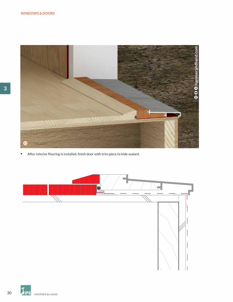
• After interior flooring is installed, finish door with trim piece to hide sealant.
12

31
RAIN SCREENS
14Introduction
4.1 Top of Wall
4.2 Top of Window
4.3 Bottom of Window
4.4 Bottom of Wall
4.5 Gable End
4.6 Horizontal Rain Screen Furring for Vertical Siding
BEST PRACTICE dETAIlS STEP-BY-STEPRAIN ScReeNS
Note to Hammer & Hand field staff:
Manufacturer’s installation instructions and architect’s construction drawings and specifications always take
precedence over the details in this Best Practices Manual. Any discrepancies with this manual should trigger discussion
with the architect about alternative approaches to their detailing. However, any alterations to architect’s plans must be
approved by the architect and such approval memorialized in an SK, ASI, RFI or other contractual method.

32
RAIN SCREENS
4
INTRoDUcTIoN To RAIN ScReeNS
Built right, rain screens are vital to modern construction in our Pacific NW climate. They are also poorly named with
multiple definitions. At Hammer & Hand, when we say “rain screen” we are referring to the ventilated rain screen, with
that all-important ventilated cavity between cladding and the rest of the wall assembly. That cavity serves two functions
for the exterior wall assembly:
1. The cavity helps protect the wall from water intrusion. By separating the cladding from the face of the wall assembly,
the rain screen cavity interrupts capillary action into the assembly and provides a drainage plane for bulk water to drain
away harmlessly.
Note: we also include a WRB (water-resistive barrier) inboard of the cavity to provide a final line of defense against bulk
water intrusion.
2. The cavity helps wall assemblies dry out. When ventilated properly, with a minimum 1/4” gap to the exterior
at bottom and top of the rain screen and a minimum 3/8” deep vertical cavity in between, the volume of air passing
through the rain screen cavity can be measured in the 10s, even 100s, of air changes per hour. This dramatically
increases the assembly’s drying potential and resiliency. This is good, particularly for highly insulated walls which
by design decrease airflow and thermal transfer across the assembly, reducing the assembly’s capacity to dry. The drying
action of the ventilated cavity behind the rain screen helps to counteract this limitation, promoting building durability.
33
RAIN SCREENS
14
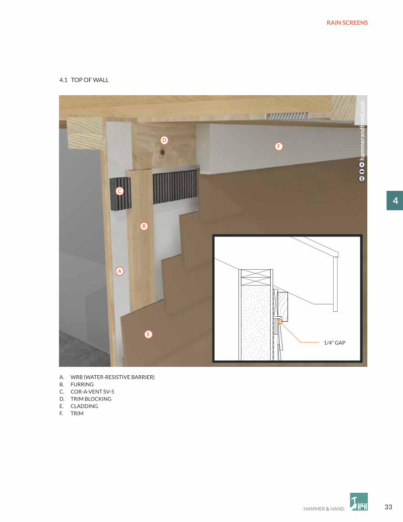
4.1 ToP oF WALL
A. WRB (WATeR-ReSISTIVe BARRIeR)B. FURRING c. coR-A-VeNT SV-5 D. TRIM BLocKINGe. cLADDINGF. TRIM
1/4” Gap
a
B
C
D
e
F
1/4” GAP

34
RAIN SCREENS
4• When the WRB is complete and lapped correctly,
the rain screen installation begins.
• Install vertical furring to correspond with the framing
method (aligned with vertical framing members).
• Use untreated 1x4 furring.
• Attach cor-A-Vent SV-5 insect blocker strip between
furring.
• Attach siding.
1 2
3 4

35
RAIN SCREENS
14
• Install blocking to attach the rabbeted trim to.
1/4” MIN. GAP
5
6

36
RAIN SCREENS
4
A. JoINT & SeAM FILLeRB. FASTFLASHc. WRB (WATeR-ReSISTIVe BARRIeR)D. INSTALLeD WINDoWe. TRIM
F. HeAD FLASHINGG. FURRINGH. coR-A-VeNT SV-5I. cLADDING
4.2 ToP oF WINDoW
B
C
D
e
F
G
H
I
a

37
RAIN SCREENS
14
• cut a slit in the WRB, fold up, and use tape to hold
the flap out of the way while the head flashing
is installed.
• Attach head flashing.
• Install vertical furring to correspond with
the framing method (aligned with vertical
framing members).
• Use untreated 1x4 furring.
• Install trim.
• Layer on WRB. Layer in a shingle method starting
at the bottom and lapping top over bottom piece.
21
3 4

38
RAIN SCREENS
4
• Apply Joint & Seam Filler to the top of the back
leg of the head flashing.
• Tool Joint & Seam Filler into place.
• Fold WRB flap back down and tape the slit to prevent
water intrusion.
5 6
• Attach remaining rain screen furring above head
flashing.
7
• Install cor-A-Vent above the window.
8
39
RAIN SCREENS
14
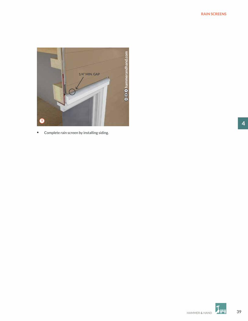
• complete rain screen by installing siding.
1/4” MIN. GAP
9

40
RAIN SCREENS
4
A. WRB (WATeR-ReSISTIVe BARRIeR)B. TRANSITIoN STRIPc. SHIMS SUPPoRTING WINDoWD. INSTALLeD WINDoW
e. FURRING F. coR-A-VeNT SV-5G. TRIMH. cLADDING
4.3 BoTToM oF WINDoW
a
B
C
D
e
F
G
H

41
RAIN SCREENS
14
• Layer on WRB. Layer in a shingle method
starting at the bottom and lapping top over
bottom.
• Install vertical furring to correspond with
the framing method (aligned with vertical
framing members).
• Use untreated 1x4 furring.
• cut pieces of cor-A-Vent SV-5 to fit flush
in between furring below window.
2
1
3

42
RAIN SCREENS
4
• Attach trim.
• can be nailed to furring.
• Install siding to complete the rain screen.
1/4” MIN. GAP
4
5

43
RAIN SCREENS
14
A. WRB (WATeR-ReSISTIVe BARRIeR)B. FURRING c. coR-A-VeNT SV-5
D. WATeR TABLee. FLASHINGF. cLADDING
1/4” MIN. GAP
4.4 BoTToM oF WALL
a
B
C
D
e
F

44
RAIN SCREENS
4
• Layer on WRB.
• Install vertical furring to correspond with
the framing method (aligned with vertical
framing members).
• Use untreated 1x4 furring.
• Attach a continuous strip of cor-A-Vent
SV-5 insect blocker at bottom of furring.
• Seal sheathing to stem wall with
Joint & Seam Filler.
2
1
3

45
RAIN SCREENS
14
• Attach water table to furring.
• Install flashing above water table.
• Install siding to complete the rain screen.
1/4” MIN. GAP
4
5
6

46
RAIN SCREENS
4
A. RooFING MATeRIALB. FLASHING c. WRB (WATeR-ReSISTIVe BARRIeR)D. FURRING
e. BLocKING FoR RABBeTeD TRIMF. coR-A-VeNT SV-5G. cLADDING
4.5 GABLe eND
a
B
C
D
eF
G

47
RAIN SCREENS
14
On Gable ends
At the sloped angle of the roof where the siding will terminate, attach small segments of furring in between full pieces.
This provides support for the ends of the lap siding where it does not meet regular furring.
x
x
x
xFURRING
SIDING SUPPoRT NAILeRS
TRIM BLocKING
coR-A-VeNT SV-5
X’S SHoW SoMe INSTANceS IN THe DIAGRAM WHeRe LAPPeD SIDING IS ATTAcHeD To NAILeR.
RooFING MATeRIAL
DASHeD LINe DeNoTeS SIDING oVeRLAP

48
RAIN SCREENS
4
A. WRB (WATeR-ReSISTIVe BARRIeR)B. VeRTIcAL FURRING c. HoRIZoNTAL FURRING D. coR-A-VeNT SV-5
e. BLocKING FoR RABBeTeD TRIMF. cLADDINGG. TRIMH. MAINTAIN qUARTeR INcH GAP
Top of Wall Reveal
4.6 HoRIZoNTAL RAIN ScReeN FURRING FoR VeRTIcAL SIDING
a
B
C
D
e
F
G
H

49
RAIN SCREENS
14
A. WRB (WATeR-ReSISTIVe BARRIeR)B. VeRTIcAL FURRING c. HoRIZoNTAL FURRINGD. coR-A-VeNT SV-5
e. WATeR TABLe ATTAcHeD To HoRIZoNTAL FURRINGF. FLASHING FoR WATeR TABLeG. cLADDING
Bottom of Wall Reveal
a
B
C
D e
F
G

50
RAIN SCREENS
4
• Rain screen installation begins after
the WRB is properly lapped and in place.
• Install vertical furring to correspond with the
framing method (aligned with vertical framing
members).
• Use untreated 1x4 furring.
2
1

51
RAIN SCREENS
14
• Attach water table.
• Install a continuous strip of cor-A-Vent SV-5
at top and bottom of the rain screen to prevent
bug entry.
• Install horizontal furring to allow attachment of
vertical siding.
• Use 1x4 furring.
• Nail on blocking for rabbeted trim, leaving space
for cor-A-Vent SV-5.
3 4
5

52
RAIN SCREENS
4 • Install flashing for water table.
• Attach vertical siding
and then trim.
6
7

53
ENVELOPES
15
Introduction
5.1 Wall Penetrations
5.2 Air Sealing
5.3 Insulation
5.4 Exterior Continuous Insulation (CI) at Walls
5.5 Wall Assembly Example
BEST PRACTICE dETAIlS STEP-BY-STEPeNVeLoPeS
Note to Hammer & Hand field staff:
High risk projects such as basement remodels, parapet walls, pool rooms, etc. require further analysis.
Manufacturer’s installation instructions and architect’s construction drawings and specifications always take
precedence over the details in this Best Practices Manual. Any discrepancies with this manual should trigger discussion
with the architect about alternative approaches to their detailing. However, any alterations to architect’s plans must be
approved by the architect and such approval memorialized in an SK, ASI, RFI or other contractual method.

54
ENVELOPES
5
INTRoDUcTIoN To BUILDING eNVeLoPeS
The building envelope is arguably the single most important determinant of building durability, energy efficiency,
and occupant comfort and health. We deliver these qualities to our buildings by carefully managing heat, air,
and moisture through envelope assemblies. Put simply, we want to limit the movement of air and heat through
our assemblies, limit the intrusion of moisture, and promote drying of any moisture that does intrude. The interplay
between heat, air, and moisture is extremely dynamic, however, and a full understanding of that interplay in any given
assembly can require extensive analysis. Nonetheless, a couple core principles can guide much of our work:
1. start by making it airtight. If you control for air, you also make major strides in controlling for heat and moisture. This
is because much of the movement of heat and moisture into and through building assemblies is carried by air. When
we stop air movement through our assemblies we also stop this air-borne problem.
2. avoid condensation where it hurts. condensation forms where relative humidity – a function of moisture
concentration and air temperature – hits 100%, aka the “dew point.” Relative humidity can reach the dew point when
(1) moisture concentration increases in a given volume of air to the point where it surpasses the air’s capacity to hold
that moisture in suspension, or (2) when air temperature decreases, reducing the air’s capacity to hold moisture
in suspension. Major problems, including building failure, arise when the dew point occurs inside building envelope
assemblies where moisture can accumulate. The most likely place for this to occur is on the surface of a building
component in an assembly. Warm concentrations of moisture, carried by air or moved via vapor drive (the diffusion
of moisture from areas of higher concentration to areas of lower concentration), hit a cold surface and the moisture
drops out of suspension and condenses on the surface. Therefore, our assemblies must be designed and built to prevent
concentrations of moisture from hitting surfaces that are cold enough to cause this condensation inside
our assemblies. Furthermore, when working with materials that are subject to mold growth we need to include
an additional safety factor in assembly design, as mold grows at relative humidity levels even lower than 100%.

55
ENVELOPES
15
Built right, a building’s exterior wall is a comprehensive system for protecting the building from the elements
and for managing heat, air, and moisture. So when we punch a hole through this system we must proceed with caution,
ensuring that we maintain the integrity of the building envelope. A moisture management system is only as strong
as its weakest link.
• electrical service and meter.
• exterior electrical outlets and lighting.
• Telecommunications and miscellaneous
low voltage (cable, phone, satellite dish
mounts, etc.).
• HVAc (electrical, refrigerant lines,
combustion piping/flues, exhaust and intake
ports, condensate drain lines, dryer
exhaust vents).
• Natural gas line and meter.
• Hose bibs.
5.1 WALL PeNeTRATIoNS
a. It is Critical That No Wall Penetrations are
Overlooked
Proper planning and sequencing will ensure that every
penetration is correctly detailed. The following is a list
of various wall enclosure penetrations that are frequently
encountered on a project:
B. Consolidate Wires
Wires should be consolidated into as few penetrations
as possible and routed through a plastic pipe that
can easily be sealed (shown below). Allow space
for future wiring changes to prevent the creation
of future wall penetrations.
Note:
one of the best methods for sealing around wires inside pipes and conduits is to use a non-hardening duct seal
electrical putty. This is especially critical at the electrical panel where the main conduit enters the building.

56
ENVELOPES
5
Duct Flashing with a Rain screen
• cut hole for duct as tight as possible.
• Space between duct and wall sheathing
to be 1/4” or less.
• Apply Joint & Seam Filler.
• Apply FastFlash to a distance of 9” from outer edge
of pipe and 2” up the sides.
• only extend downward slightly so FastFlash does
not adhere to the back side of the transition strip.
9”
• Stick top edge of transition strip membrane
to FastFlash.
• Bead and tool FastFlash to the top edge
of transition strip.
21
3 4
57
ENVELOPES
15
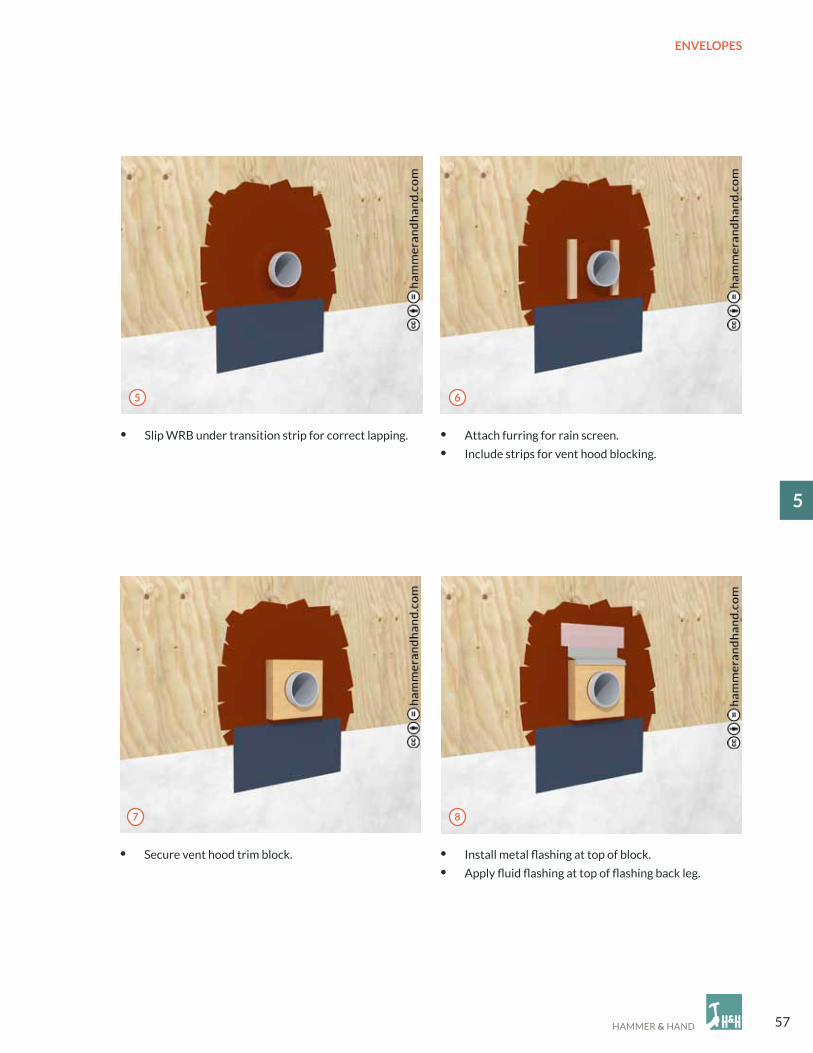
• Slip WRB under transition strip for correct lapping. • Attach furring for rain screen.
• Include strips for vent hood blocking.
• Secure vent hood trim block. • Install metal flashing at top of block.
• Apply fluid flashing at top of flashing back leg.
5 6
7 8

58
ENVELOPES
5
• complete rain screen by adding siding and caulking the sides of the duct blocking,
not the top or bottom.
• Attach vent hood.• Attach flashing to vent hood blocking strips.
9 10
11
59
ENVELOPES
15
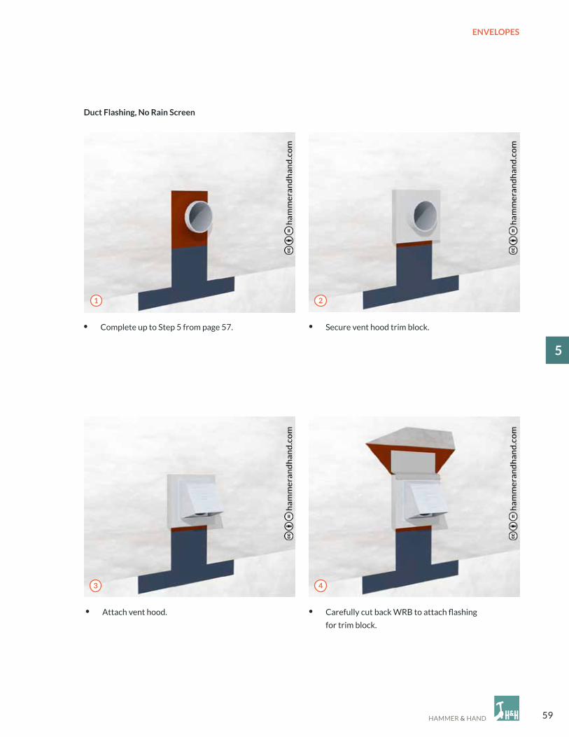
• complete up to Step 5 from page 57. • Secure vent hood trim block.
• Attach vent hood. • carefully cut back WRB to attach flashing
for trim block.
Duct Flashing, No Rain screen
21
3 4

60
ENVELOPES
5
• Apply Joint & Seam Filler at the top of the flashing
and tool into place.
• Fold down WRB flap and tape slits closed.
• complete rain screen by adding siding and caulking the sides of the duct blocking, not the top or bottom.
7
5 6

61
ENVELOPES
15
5.2 AIR SeALING
Airtight construction controls the flow of air and therefore the flow of airborne heat and moisture into and through
the building envelope. It needs to be approached in a comprehensive manner on all sides of the envelope. The most
difficult aspect of air sealing is where dissimilar materials intersect, especially in complex geometry. The details that
follow illustrate strategies for tackling some of the most commonly encountered intersections.
a
B
A. JoINT AND SeAM SeALANT oR APPRoVeD TAPeB. SILL SeAL
1. To function as air barrier, foundation must be structural reinforced concrete.
2. Prevent sheathing-to-concrete contact.
Foundation to sheathing

62
ENVELOPES
5
at sheathing
a
B
C
D
Materials
A. RIGID PANeL WITH INTeGRAL WRB (ZIP SHeATHING oR SIMILAR)
Apply approved sealant at all joints, seams, and penetrations.
Apply fluid applied membrane at interior of punched openings.B. RIGID PANeLS WITH FLUID APPLIeD WRB
Apply fluid applied system at punched openings, seams, and penetrations.
cover entire exterior plane of envelope with fluid applied WRB.
c. RAW RIGID PANeL ReADY FoR FABRIc WRB
Apply fluid applied system at punched openings, joints, and penetrations.
Tile-in fabric WRB product into wet set transition sheets.
D. See SecTIoN 5.1 DUcT FLASHING WITH A RAIN ScReeN
63
ENVELOPES
15
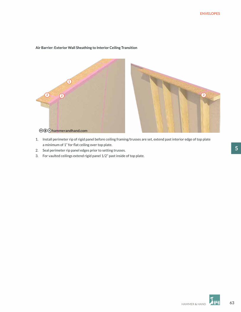
air Barrier: exterior Wall sheathing to Interior Ceiling Transition
2
1
2 2
1. Install perimeter rip of rigid panel before ceiling framing/trusses are set, extend past interior edge of top plate
a minimum of 1” for flat ceiling over top plate.
2. Seal perimeter rip panel edges prior to setting trusses.
3. For vaulted ceilings extend rigid panel 1/2” past inside of top plate.

64
ENVELOPES
5
Wall to Ceiling/Roof
a
B
a
B
C
A. AIR BARRIeR AT ceILINGB. JoINT AND SeAM SeALANT oR APPRoVeD TAPe
A. 1.5” SeRVIce cAVITYB. DRYWALLc. RIGID PANeL WITH SeALANT oR TAPe
65
ENVELOPES
15
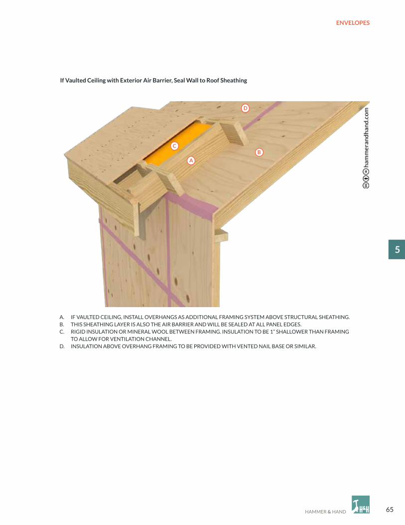
If Vaulted Ceiling with exterior air Barrier, seal Wall to Roof sheathing
a
BC
D
A. IF VAULTeD ceILING, INSTALL oVeRHANGS AS ADDITIoNAL FRAMING SYSTeM ABoVe STRUcTURAL SHeATHING.B. THIS SHeATHING LAYeR IS ALSo THe AIR BARRIeR AND WILL Be SeALeD AT ALL PANeL eDGeS. c. RIGID INSULATIoN oR MINeRAL WooL BeTWeeN FRAMING. INSULATIoN To Be 1” SHALLoWeR THAN FRAMING To ALLoW FoR VeNTILATIoN cHANNeL.D. INSULATIoN ABoVe oVeRHANG FRAMING To Be PRoVIDeD WITH VeNTeD NAIL BASe oR SIMILAR.

66
ENVELOPES
5
5.3 INSULATIoN
Poor spacing at Corner
with Insufficient Clearance
Proper spacing at Corner
Cavity Fill
Allow for proper access in all areas to facilitate complete and thorough filling of cavity.
1x MATeRIAL
1x MATeRIAL
By limiting the flow of heat through the building envelope, insulation plays a fundamental role in delivering occupant
comfort and energy efficiency. To maximize the effectiveness of the insulative layer, we need to build the structure to
accept the insulation and then need to install the insulation properly. The details that follow describe a handful of critical
standard insulation applications.
Note: By reducing the flow of energy through the envelope, affecting the movement of moisture, and altering airflows,
adding insulation can cause unintended consequences on building durability. The design of insulated assemblies must
therefore be guided by an understanding of building physics and hygrothermal performance, and installation must be
completed as designed.
Framing Example at an Inside Corner:

67
ENVELOPES
15
Dense Pack Blown-In Cellulose
• At completion of project, insulation is to be enclosed on all 6 sides with rigid material to prevent
wind washing/convection losses and settling. The specific quantity of material to be installed should always
be calculated and confirmed by site superintendent. *See bag count at bottom of next page.
• ensure good access to all areas for proper fill.
Netting
• Inset stapling at corner of stud to prevent intrusion of insulation to front of stud.
• Use dense pack specific netting material.
Netting is to be taut prior to fill. check density after 10% of work is complete to confirm proper installation.
At initial completion, review integrity of installation and remedy any under-filled areas.
Material density determined by manufacturer, should feel like solid felt. Keep dry with No exposure to bulk water
during construction.

68
ENVELOPES
5
Fiberglass
• At completion of project, insulation is to be enclosed on all 6 sides with rigid material to prevent
wind washing/convection losses and settling. The specific quantity of material to be installed should always
be calculated and confirmed by site superintendent. *See bag count below.
• ensure good access to all areas for proper fill.
Netting
• Inset stapling of netting at corner of stud to prevent intrusion of insulation to front of stud.
• Utilize netting per fiber glass manufacturer’s specifications.
Netting is to be taut prior to fill. check density after 10% of work is complete to confirm proper installation.
At initial completion, review integrity of installation and communicate any under-filled areas to insulation contractor.
check building specifications for desired density. Keep dry during construction.
1. ‘Dense-Pack’ feels like a firm mattress. See manufacturer’s documentation for lbs/ft3 specifications.
2. ‘Standard Fill’ feels like a firm pillow. See manufacturer’s documentation for lbs/ft3 specifications.
* Bag Count Example:
435 SF of 2 x 6 wall
Framing factor of 18% (area taken up by wall framing)
(435 ft2 x 5.5/12 ft) x (100% - 18%)
(435 ft2 x .458 ft) x .82
199.375 ft3 x .82 = 163.5 ft3
Example: Fiberglass might be 1.8 lbs/ft3.
The 435 ft2 area needs 294.3 lbs of material.
Bags are 28 lbs/each, this wall needs 10.5 bags
of material.

69
ENVELOPES
15
attic Insulation
Loose Fill in Attics
• Protect from wind-washing at perimeter, especially where close to roof venting.
• Roof baffles for soffit venting to terminate no less than 12 inches above cellulose to prevent wind from
displacing material.
• Baffles between rafters to be continuous from rafter to rafter
(do not use baffles which are fastened to roof sheathing). Must fill full width of cavity.
• Maximum slope of ceiling below loose fill: 5/12.
• Do not use blown-fiberglass due to light density/wind washing.
• Insulation depth markers to be installed per manufacturer’s specification.
Note: These areas are outside the thermal envelope and air barrier and are not suitable for mechanical systems or
ductwork.

70
ENVELOPES
5
Attic Walls
• Where vertical walls are encountered in attic spaces (this condition occurs where ceiling heights change) install
rigid material on attic side of framing and insulate from interior so area can be readily inspected post-installation
of insulation material.
Attic Hatch
• ensure proper clearance is present from ceiling to bottom of rafters to allow for access, post-installation
of insulation; if current location does not allow for needed clearance, relocate hatch.
• construct “dam” of plywood or other durable rigid panel (cardboard is not sufficient) to a height of final insulation
depth plus 2.” Minimum height above dam to be 30” to allow for access to attic. Minimum rough framed opening
of hatch per code to be 22” x 30.”
• Insulate hatch area with rigid insulation to the minimum R-value of general attic area. Allowable gap at perimeter
of insulation panel to be a maximum of 1/4” per side. Hatch to be integrated into air barrier necessary to maintain
airtightness.

71
ENVELOPES
15
Foil-Faced Polyisocyanurate (Polyiso)
• exterior surface may be used as a WRB, with manufacturer approval.
• Install tape at seams per manufacturer specification.
1. Must use J-Roller on tape with good detailing to eliminate ‘Fish-Mouthing.’
expanded Polystyrene (ePS)
• Multiple layers with staggered seams recommended to accomodate product shrinkage.
• While exterior surface may be used as a WRB, we do not recommend it.
1. Install tape at seams per manufacturer specification.
2. Must use J-Roller on tape with good detailing to eliminate ‘Fish-Mouthing.’
extruded Polystyrene (xPS)
• Limit use of this product as the material has a high Global Warming Potential.
• exterior surface may be used as a WRB.
1. Install tape at seams per manufacturer specification.
2. Must use J-Roller on tape with good detailing to eliminate ‘Fish-Mouthing.’
Types of exterior Rigid Foam and Installation Instructions
5.4 exTeRIoR coNTINUoUS INSULATIoN (cI) AT WALLS
continuous exterior insulation is like a winter sweater wrapping a building. It is also a key component in establishing
a thermal bridge-free building envelope. Thermal bridges are penetrations in a building’s insulation layer, like the wood
studs of a stud wall for example, that allow heat to escape and cold to intrude through the building envelope.
In otherwise high performance assemblies, thermal bridges can be a source of tremendous energy loss and condensation
risk. By insulating around would-be thermal bridges, continuous exterior insulation establishes a thermal break between
these building components and the exterior environment. As with insulation in general, as we introduce exterior
insulation we need to understand and detail for the effects this insulation will have on moisture movement through
the overall assembly.

72
ENVELOPES
5
• For cutting, use knives and (for ePS and xPS)
“hot wire” devices; minimize use of saws to limit
dust for site cleanliness, carpenter health,
and to prevent tool damage.
• If thicker than 2,” install in multiple layers with
staggered seams to prevent thermal bypass.
• Fastening: consult manufacturer specifications
or structural architectural drawings.
PHoTo oF KARUNA FoIL BASeD FoAM
1. Install first layer of rigid insulation with limited
number of nails or screws with washers.
2. Install second layer of rigid insulation with limited
number of nails or screws with washers.
3. Fasten furring with screws; spacing and fastener size
to be decided by weight of siding material
and spacing of furring.
When Rain Screen Furring is to be Installed 0ver Rigid Insulation
PIc oF MeYeR FoAM cUTTING TABLe
Rigid Foam Installation
Steps:
73
ENVELOPES
15
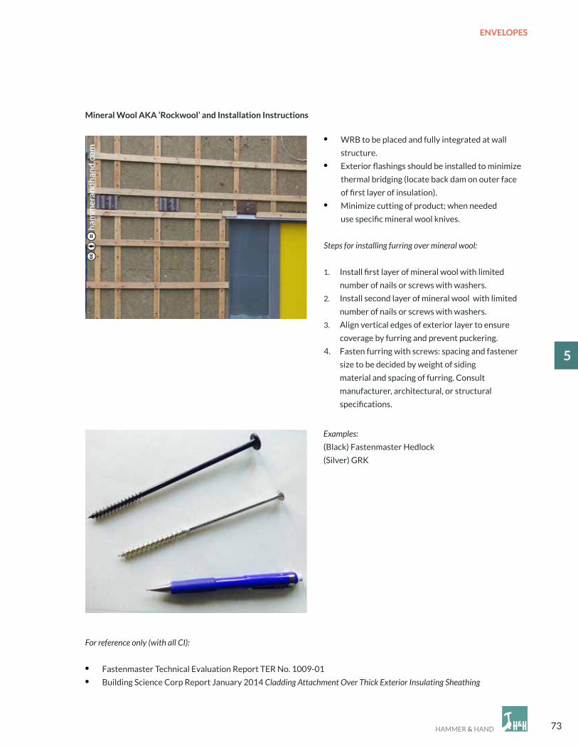
• WRB to be placed and fully integrated at wall
structure.
• exterior flashings should be installed to minimize
thermal bridging (locate back dam on outer face
of first layer of insulation).
• Minimize cutting of product; when needed
use specific mineral wool knives.
Steps for installing furring over mineral wool:
1. Install first layer of mineral wool with limited
number of nails or screws with washers.
2. Install second layer of mineral wool with limited
number of nails or screws with washers.
3. Align vertical edges of exterior layer to ensure
coverage by furring and prevent puckering.
4. Fasten furring with screws: spacing and fastener
size to be decided by weight of siding
material and spacing of furring. consult
manufacturer, architectural, or structural
specifications.
mineral Wool aKa ‘Rockwool’ and Installation Instructions
Examples:
(Black) Fastenmaster Hedlock
(Silver) GRK
For reference only (with all CI):
• Fastenmaster Technical evaluation Report TeR No. 1009-01
• Building Science corp Report January 2014 Cladding Attachment Over Thick Exterior Insulating Sheathing

74
ENVELOPES
5
A. DeNSe PAcK INSULATIoNB. SHeATHING WITH INTeGRAL WRBc. JoINT & SeAM FILLeRD. MINeRAL WooL INSULATIoNe. FLUID APPLIeD SYSTeM AT PUNcHeD
oPeNINGF. ceDAR SIDING (VeRTIcAL)G. SILL PAN FLASHINGH. 2-WAY RAIN ScReeN FURRINGI. WINDoW BUcKJ. FRAMeD STUD WALLK. HeAD FLASHING
Note: Metal flashings not to return back to
sheathing.
5.5 WALL ASSeMBLY exAMPLe
a B
C
D
e
F
G
H
I
J
K

75
ENVELOPES
15
The example on page 74 combines an exterior layer of mineral wool insulation, ZIP Sheathing as air barrier and water-
resistive barrier, fluid-applied flashing at rough openings, and dense pack insulation (cellulose or fiberglass)
in an interior stud wall for a super insulated, vapor open, and resilient high performance wall assembly. The diagrams
below show how the assembly manages air, heat, water, and vapor.
DRYWALL
DeNSe PAcK INSULATIoN
STUD WALL
SHeATHING WITH INTeGRAL WRB
MINeRAL WooL
RAIN ScReeN FURRING
SIDING
A. SHeATHING WITH INTeGRAL WRB A.PRIMARY BARRIeR: SIDING
B. SecoNDARY BARRIeR:
MINeRAL WooL
c. FINAL BARRIeR: SHeATHING
WITH INTeGRAL WRB
D. RAIN ScReeN ALLoWS BULK
WATeR To DRAIN AWAY
A. exTeRIoR MINeRAL WooL INSULATIoN
B. DeNSe PAcK INSULATIoN
A. RAIN ScReeN DRIeS
cLADDING AND ASSeMBLY
B. ASSeMBLY IS VAPoR oPeN IN
BoTH DIRecTIoNS, THoUGH
THe SHeATHING WITH
INTeGRAL WRB SLoWS VAPoR
MoVeMeNT FRoM INTeRIoR.
MINeRAL WooL ALSo WARMS
SHeATHING, WHIcH
eNcoURAGeS VAPoR
DIFFUSIoN.


77
ROOFS
16
6.1 Kick-out Flashing
6.2 Vented and unvented Roof Assemblies
6.3 Parapet Walls
6.4 Flat Roof Assemblies
BEST PRACTICE dETAIlS STEP-BY-STEPRooFS
Note to Hammer & Hand field staff:
Manufacturer’s installation instructions and architect’s construction drawings and specifications always take
precedence over the details in this Best Practices Manual. Any discrepancies with this manual should trigger discussion
with the architect about alternative approaches to their detailing. However, any alterations to architect’s plans must
be approved by the architect and such approval memorialized in an SK, ASI, RFI or other contractual method.

78
ROOFS
6
6.1 KIcK-oUT FLASHING
• Install FastFlash along the wall at the roof edge.
• Peel and Stick along the edge of the roof and lap over
top of fascia.
• Be sure to leave space between the end of the fascia
and the wall where FastFlash, WRB, and siding
can slide up.
1”
• Stick top edge of transition strip membrane
to FastFlash.
• Bead and tool FastFlash to the top edge
of transition strip.
1
3 4
4”
8”
2
2”
Whenever a roof surface abuts a vertical wall surface, moisture intrusion and rot become a risk at the connection
between the two planes. Kick-out flashing, a somewhat forgotten practice except by the best roofers, addresses this risk
at the most vulnerable intersection between sloped roofs and walls: the drip edge.

79
ROOFS
16
• Nail on starter strip of roofing material.
• Attach drip edge.
• Attach roofing felt. extend 4” up the wall.
• Install Peel and Stick the entire length
of the roof-to-wall intersection.
8”
5 6
7 8

80
ROOFS
6
• Install first course of shingles.
Kick Flashing Guide
Note: All kick-out flashing fabricated on site
must have welded seams.
• Fasten kick flashing in upper right corner.
step Flashing Guide
Note: Align with top edge of shingle course.
4”
4”
8”
9
10
5”
5”8”
110 ̊
8”
5”
5”
110°
8”
4”
4”

81
ROOFS
16
• Fasten stepped flashing.
• 2” minimum overlap with preceding piece of flashing.
Top of flashing piece should align with
top of shingle course.
• continue alternating shingle course and stepped
flashing until the roof is complete.
• Install Peel and Stick over the stepped flashing. • Slip WRB as high and tight as possible under
the transition strip membrane.
2” MIN. GAP
11 12
13 14
82
ROOFS
6
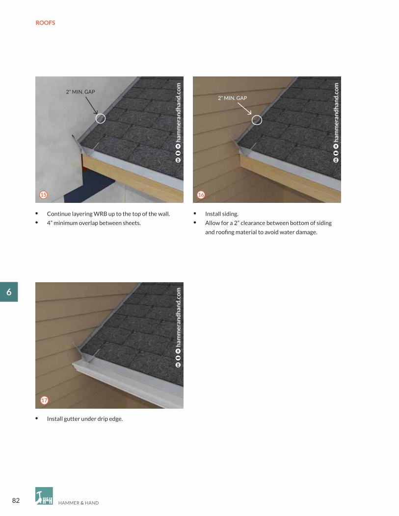
• continue layering WRB up to the top of the wall.
• 4” minimum overlap between sheets.
• Install siding.
• Allow for a 2” clearance between bottom of siding
and roofing material to avoid water damage.
2” MIN. GAP2” MIN. GAP
• Install gutter under drip edge.
17
15 16

83
ROOFS
16
6.2 VeNTeD AND UNVeNTeD RooF ASSeMBLIeS
Vented Roofs (For Pitches of 3:12 or above)
When detailed correctly, vented roofs have a long, successful track record in the Pacific Northwest. Vented roofs
provide the capacity for moisture to be removed from the underside of roof sheathing via convection currents
in the vent cavity. Because today we as an industry are insulating below the vented cavity as standard practice,
the building itself is no longer heating the cavity. So, convection currents need to be carefully designed.
To establish sufficient stack effect for these convection currents:
• Install exterior air inlets at a location lower than outlets. opposing vents with no or minimal elevation change will
not generally provide sufficient airflow.
• Maintain a free-flowing channel between vents the full width of the rafter bay and with a minimum of 1” depth.
Note that the drying capacity of vented roofs can easily be short-circuited by bad workmanship or flawed design.
Be sure to avoid these four pitfalls:
• Bulk water intrusion via water leaks from outside (poor workmanship).
• Air-borne vapor intrusion via air leaks from inside (poor workmanship).
• constricted airflow due to insulation baffles not fully spanning from rafter to rafter (poor workmanship).
• Vapor drive from inside (poor design).
Net Free Area (NFA) of exterior venting is to be a minimum of 1/300ths of the horizontal plane below the roof with equal
parts at top and bottom. When in doubt, follow local code.
Unvented Roofs
Unvented roofs are increasingly common due to design priorities. An understanding of heat, air, and moisture as well
as the causes of condensation is critical in detailing unvented roof assemblies. Potential pitfalls to avoid include:
• Incorrect ratio of vapor impermeable insulation (directly under the roofing and substrate, if present) to the vapor
open insulation beneath it. If the vapor impermeable insulation is too thin then its bottom surface can be cold
enough to allow condensation where it meets the vapor open insulation.
• Poor air sealing. If the assembly is not airtight then air movement through the assembly can carry moisture
concentrations into the assembly, with significant risk of condensation.
• careless detailing of partial penetrations. If not properly detailed, partial penetrations into the unvented roof
assembly (for things like can lights or ceiling fans) can undermine the insulation and/or air tightness strategies
alluded to above.
• Insufficient fill below the impermeable insulation layer. If air gaps are present between insulation layers, convection
currents can significantly reduce the performance of the assembly and compromise durability.
Two potential unvented roof assemblies:
1. Preferred: Monolithic continuous exterior insulation (cI) above structural sheathing.
• 40% of insulation R-value to be above sheathing. If not feasible, additional analysis required.
• Roof sheathing to be air-sealed.
• cI to be installed in multiple layers to limit insulation by-pass from gapping of insulation.

84
ROOFS
6
2. Acceptable if above is not feasible: closed-cell Spray-Polyurethane Foam (ccSPF) at bottom of roof sheathing.
• R-value of ccSPF to be 40% of total assembly. If less, analysis is required.
• No mechanical systems (electrical, plumbing, HVAc, fire suppression, etc.) can intrude into ccSPF layer.
• Insulation below ccSPF is to be blown-in fiberglass, blown-in cellulose, or open-cell Spray-Polyurethane Foam
(ocSPF). No batt materials.
Because the drying capacity of unvented roof assemblies is inherently lower than vented ones, it is especially critical to
control built-in moisture during construction. control construction moisture content with tenting or temporary roofing
when necessary. Moisture content in roof structure must be less than 18% prior to covering. Rigid insulation (if present)
must be kept dry.
Roof assemblies must control for exterior moisture in a monolithic and complete fashion. Test roofing membranes for
integrity prior to covering from below. In unvented ‘flat’ or low-slope roofs with parapets, perform a full ‘flood’ test to
ensure leak-free installation of roofing membrane.
Drying of unvented roofing assemblies is, by definition, only provided to the interior. Therefore, moisture analysis of
interior conditions and long-term management strategy is required at all wet locations or areas of high humidity genera-
tion such as steam showers, kitchens, baths, laundry, and pools. Special guidance and attention is required when select-
ing and installing roofing systems over these high humidity areas.
Note: For info about attics, see pg. 69: Attic Insulation

85
ROOFS
16
6.3 PARAPeT WALLS
Parapet walls are a difficult detail with a long history of failure. Unlike standard exterior walls, parapet walls
are exposed to the elements on three sides. Furthermore, parapets are often inadvertently connected to interior
space via balloon framing, gaps in structure, or penetrations for wiring and mechanicals, introducing warm, moist
interior air into the assembly and potential condensation. To address these conditions, detailing must
provide excellent bulk water management of roofing, parapet wall, and parapet cap, venting to promote drying,
and careful attention to separating the parapet from interior spaces.
1. Height of roofing at wall: minimum of 12” to top of parapet.
• Do not lap TPo over top of parapet unless required by unique construction conditions.
2. Top of parapet, below cap, to be sealed with fluid applied flashing.
3. Venting in wood framed parapets:
• Provide venting to each wall cavity.
• If cavity is greater than 12” above roof insulation, provide high/low venting in each wall cavity.
• can use round/louvered ‘soffit vents’ to limit bulk water intrusion if venting holes are in exposed
locations.
• For areas which do not need above, cover hole with bug screen.
• ensure ventilated siding cavity is correctly vented yet covered against bulk water intrusion at top.
4. Railing Attachments
• Side wall: see Section 6.4: Flat Roof Assemblies.
5. Special considerations
• Strive to avoid penetrations through top of the parapet wall. If unavoidable, get further direction from
design team before proceeding.
• Likewise, strive to avoid balloon framing of the parapet wall. If unavoidable, get further direction from the
design team before proceeding.

86
ROOFS
6
Venting in wood framed parapets:
• Provide venting to each wall cavity.
• If cavity is greater than 12,” provide
high/low venting in each wall cavity.
• can use round/louvered ‘soffit vents’
to limit bulk water intrusion if venting
holes are in exposed location.
• For areas which do not need above,
cover hole with bug screen.
• Insulate within parapet wall cavity
to depth of roof insulation (if present).
• Roof membrane must lap up wall
to minimum of 12” above roof plane
or per specifications, whichever
is greater.
• Terminate roofing on parapet wall with
mechanically fastened termination bar.
A. RooF MeMBRANeB. TeRMINATIoN BARc. INSULATIoND. VeNTILATIoN HoLeS
2
1
Venting and Roofing for Parapet Walls
a
B
C
D
C

87
ROOFS
16
3
• Top of parapet below cap to be sealed
with vapor permeable FAF.
• Install either fluid applied WRB from
termination bar up and over
parapet top or cover transition
with transition strip.
• counterflash termination bar with fluid
applied flashing (FAF) to be encapsulated
at both top and face, covering fasteners.
A. APPRoPRIATe FAF
4
a

88
ROOFS
6
Complete Parapet Wall

89
ROOFS
16
A. 24 GAUGe MINIMUM PARAPeT cAPB. WeDGec. c-cLIP D. FLUID APPLIeD FLASHINGe. VAPoR PeRMeABLe
TRANSITIoN STRIPF. 1/2” SHeATHINGG. WRBH. VeNT HoLeSI. 1x4 FURRINGJ. SIDING
Interior
a
B
C
e
F
G
D
H
I
J
D

90
ROOFS
6
A. 24 GAUGe MINIMUM PARAPeT cAP
B. WeDGec. c-cLIP D. FLUID APPLIeD FLASHINGe. VAPoR PeRMeABLe
TRANSITIoN STRIPF. 1/2” SHeATHINGG. RooFINGH. TeRMINATIoN BARI. FURRINGJ. SIDING/TRIM
a
B CD
e
F
G
H
I J
exterior
D

91
ROOFS
16
6.4 FLAT RooF ASSeMBLIeS
a
BC
D
e
F
G
Continuous Insulation on Top of sheathing (exterior CI) with Fiber-Fill in Joist Cavity
This is how to detail an unvented roof assembly for flat and low slope roofs.
Before constructing a flat roof assembly, please refer to the unvented roof assembly comments under 6.2 Vented and
Unvented Roof Assemblies and, if applicable, 6.3 Parapet Walls. There is absolutely no room for error in the detailing
and installation of roofing and air sealing in these assemblies. This step should be closely monitored and tested prior to
acceptance of work. Do not rush this.
A. MINIMUM R-VALUe oF exTeRIoR cI DeTeRMINeD BY ToTAL R-VALUe oF INSULATeD ASSeMBLY
(See ALSo: UNVeNTeD RooF SecTIoN).B. coVeR BoARD IN HIGH IMPAcT AReASc. RooFING SUBSTRATe To HAVe MINIMUM SLoPe oF 1/4” D. FIBeR FILL: BLoWN-IN oNLY, eNSURe coMPLeTe
coNTAcT To BoTToM oF SHeATHING
e. RecoMMeNDeD RooFING IS TPoF. NeVeR PeNeTRATe PARAPeT ASSeMBLY THRoUGH
THe ToPG. HoLD oFF WALL BY A 1/8” GALVANIZeD oR STAINLeSS
STeeL WASHeR FoR DRAINAGe GAP

92
ROOFS
6
a
B
Penetrating Post
Use this option when it’s necessary for the rail to penetrate a low slope roofing membrane.
Vented Post Detail with low slope Roof Penetration
C
A. TPo BooTB. TUBe STeeL oR eqUALc. SeAL ToP oF BooT To PoST WITH coMPATIBLe SeALANT
Note: If post (B) penetrates into thermal envelope, encapsulate with closed cell spray foam to mitigate condensation.

93
BASEMENTS
17
7.1 Basement, new Construction
7.2 Capillary Break
7.3 Sub Slab Vapor/Soil Barrier
7.4 Basement Retrofit
BEST PRACTICE dETAIlS STEP-BY-STEPBASeMeNTS
Note to Hammer & Hand field staff:
Manufacturer’s installation instructions and architect’s construction drawings and specifications always take
precedence over the details in this Best Practices Manual. Any discrepancies with this manual should trigger discussion
with the architect about alternative approaches to their detailing. However, any alterations to architect’s plans must
be approved by the architect and such approval memorialized in an SK, ASI, RFI or other contractual method.

94
BASEMENTS
7
7.1 BASeMeNT, NeW coNSTRUcTIoN
In addition to structural integrity, we need to address two priorities when constructing new basements: moisture
protection and thermal control. With new construction, we have the luxury of installing our moisture management
layers outboard of the foundation wall. our preferred method uses a fluid-applied elastomeric membrane applied
directly to the exterior face of concrete followed by a drainage mat with integrated filter fabric. Water in the soils
adjacent to the foundation wall can then drain down to a drainage pipe installed in a bed of gravel next to the foundation
wall footing. A bentonite waterstop laid atop a capillary break on the footing inhibits moisture movement through
the cold joint between foundation footing and foundation wall. To limit heat, air, and moisture transmission
we use low or medium density spray foam insulation in a stud wall (or, alternatively, a continuous layer of ePS against
the concrete wall combined with blown-in insulation in a stud wall immediately inboard of that ePS). The concrete slab
sits on 2-6” of rigid insulation with a perimeter thermal break and is then topped with a soil barrier membrane,
completing the basement’s thermal and moisture isolation from the earth.

95
BASEMENTS
17
A. DRYWALLB. 2x4 STUD WALLc. 1- 2 1/2” GAP BeTWeeN STUD WALL
AND FoUNDATIoN WALLD. LoW oR MeDIUM DeNSITY SPRAY FoAM INSIDe
AND BeHIND STUD WALL e. FoUNDATIoN WALLF. FLUID APPLIeD eLASToMeRIc MeMBRANeG. DIMPLeD DRAINAGe MeMBRANe WITH GeoTexTILe FABRIcH. MINIMUM 4” LAYeR WASHeD AND cLeANeD
(No FINeS) cRUSHeD SToNe oR GRAVeL
DeTAIL oN NexT PAGe
I. 4” DRAINAGe PIPe, HoLeS DoWNJ. 2-4” RIGID INSULATIoNK. NoT SHoWN: IF RIGID FoAM INSULATIoN IS USeD oN AN exTeRIoR WALL, PRoTecT THe ToP WITH
A coATING oR PRoTecTIoN BoARD. BeLoW GRADe, PLAce INSULATIoN BeTWeeN DIMPLe DRAINAGe MAT AND eLASToMeRIc WATeRPRooF MeMBRANe. FoAM MUST Be PRoTecTeD WITH DURABLe FINISH WHeN exTeNDeD ABoVe GRADe.
a
B
C
D
e
F
G
H
IJ
New Construction

96
BASEMENTS
7
New Construction Close Up
A. HeAVY DUTY GeoTexTILe FILTeR FABRIc B. WASHeD GRAVeL FILLc. 4” DRAINAGe PIPe, HoLeS DoWN. ALWAYS LocATe BeLoW
BoTToM oF SLAB.D. FooTINGe. DIMPLeD DRAINAGe MeMBRANe WITH GeoTexTILe FABRIcF. FLUID APPLIeD eLASToMeRIc WATeRPRooF MeMBRANeG. exPANDING JoINT WATeRSToP*H. FoUNDATIoN WALL
I. FLUID APPLIeD cAPILLARY BReAK (See SecTIoN 7.2)
J. LoW oR MeDIUM DeNSITY FoAMK. DRYWALLL. FLooR SLAB M. 12 MIL ReINFoRceD SoIL BARRIeR WITH SeALeD
SeAMS (See SecTIoN 7.3)
N. 2-4” RIGID INSULATIoN
*Waterstops should be installed at all joints below grade. Place water stop a minimum of 3” to the exterior surface
of the wall.
Note: Utilize pipe cast into footings to interconnect sub-slab drainage zone.
a
B
C
D
e
F
G
H
I
J
N
m
l
K

97
BASEMENTS
17
FooTINGS AND STeM WALL coATeD WITH cAPILLARY BReAK/FLUID APPLIeD WATeRPRooFING.
7.2 cAPILLARY BReAK
FLUID-APPLIeD cAPILLARY BReAK.FLUID-APPLIeD eLASToMeRIc WATeRPRooF MeMBRANe.
BeNToNITe WATeRSToP
cAPILLARY BReAK

98
BASEMENTS
7
7.3 SUB SLAB VAPoR/SoIL BARRIeR
TAPeD SeAMS AND SeALeD PeNeTRATIoNS IN THe SUB SLAB VAPoR AND SoIL BARRIeR.

99
BASEMENTS
17exISTING coNDITIoNS
• Remove existing concrete basement floor with concrete
saw or a 75lb+ jackhammer.
• cut concrete floor at least 14” away from foundation wall
(wider if footing is in the way).
• Leave 16” sections of the concrete floor (contact points) every
15’-20’ to keep foundation wall stable.
7.4 BASeMeNT ReTRoFIT
Interior French Drain Installation step-by-step
1
Basement retrofits require special care and attention to moisture management, but with a unique constraint in most
cases: all our efforts are limited to the inside of the structure. our experience with basement retrofits is that there
are two types of existing basements: ones that leak now and ones that will leak in the future. Therefore, our retrofit
strategy is to establish a robust behind-the-wall drainage system interconnected to an active dewatering system. First,
we create an interior French Drain to capture any water that leaks through foundation walls. Second, we install a dimple
drainage mat on the inside face of the foundation wall to ensure that water is directed down to that French Drain. Third,
we seal up and insulate the assembly to control for vapor and thermal transfer.

100
BASEMENTS
7
• After concrete has been
removed, dig a trench 12”
from top of concrete floor.
• Use a sump pump to manage
water during digging.
• Always use a sump pump
basin with air/vapor tight lid.
• The sump basin should
be surrounded by at least
6 to 8 inches of 3/4” washed
gravel.
• Do NoT undermine footing
or foundation wall, maintain
a 45 degree angle.
• Install heavy duty geotextile fabric
in trench.
• Start from sump and lay
perforated plastic pipe
(holes down).
• Typical pipe slope/pitch
is 1/4” per 5ft.
• This discharge line is typically
a 1-1/2” inch PVc schedule 40
(solid) pipe.
• Always place in-line check valve
directly above pump.
12”
45°
2
3
4

101
BASEMENTS
17
• Run dimple drainage mat at foundation wall
to trench for weep.
• Fill trench with clean, crushed stone (3/4” to 1-1/2”).
• The cut concrete edge must be sprayed down
and brushed so the new concrete has a clean surface
to bond to.
• Pour new concrete flush with existing floor.
Note: It is critical that dimple drainage
mat is terminated before intersecting embedded wood
beams and the top of the foundation wall.
This prevents the wood from coming into contact
with the humid air between the foundation wall
and dimple mat.
5 6
7

102
BASEMENTS
7
• Frame basement wall 1” off wall with a capillary break
under bottom plate.
• Install vertical floor to ceiling fire blocking per code.
additional Information
Note: Warn clients against using carpet and vapor
impermeable flooring on existing uninsulated slabs.
Flooring Options Going Forward:
1. Leave as is (highest risk).
2. Add vapor-tight dimple mat over existing slab
and install new flooring.
3. Add rigid insulation over existing slab and install
new flooring.
4. Remove existing slab and install rigid insulation,
heavy duty sealed soil barrier, and new slab.
Always Provide Radon System Option:
Provide electrical near the sump pump to allow
for easy addition of a radon system if necessary.
• Spray foam rim joist and foundation wall.
• Install Drywall.
8 9
10

103
CRAWLSPACES
18
8.1 General Guidelines
8.2 new Construction: Conditioned with Insulated Slab
8.3 Retrofit Option 1: Conditioned with Soil Barrier
8.4 Retrofit Option 2: Vented with Floor Encapsulation
BEST PRACTICE dETAIlS STEP-BY-STEPcRAWLSPAceS
Note to Hammer & Hand field staff:
Manufacturer’s installation instructions and architect’s construction drawings and specifications always take
precedence over the details in this Best Practices Manual. Any discrepancies with this manual should trigger discussion
with the architect about alternative approaches to their detailing. However, any alterations to architect’s plans must
be approved by the architect and such approval memorialized in an SK, ASI, RFI or other contractual method.

104
CRAWLSPACES
8
8.1 GeNeRAL GUIDeLINeS
Options:
• Acceptable option for crawlspaces without
mechanicals or ductwork.
• Install new plastic soil barrier with lapped
seams. Heavy duty soil barrier with sealed
seams optional.
• Air space should be maintained between floor
and spray foam if underfloor hydronic tubing
is being used for radiant heat.
To Know Before Building or Retrofitting a Crawlspace:
• Moisture management: all surface and ground water must be properly managed prior to sealing
and insulating a crawlspace.
• Do NoT route ductwork through unconditioned attics or crawlspaces. All water supply lines
must be insulated even in a conditioned crawlspace.
• cleanup: crawl must be thoroughly cleaned of all dust and debris after construction is complete
and any damage to the soil barrier must be repaired.
• Treating the crawlspace like a mini-basement
with an insulated wall and slab is the highest
performance crawlspace option.
1. New Construction: Conditioned Crawlspace
with Insulated slab (8.2)
2. Retrofit: Conditioned Crawlspace
with soil Barrier (8.3)
• This is the best retrofit option in crawlspaces
that contain mechanicals or ductwork,
or are interconnected with a conditioned
basement.
• Install a Sealed Seam heavy duty (12 mil)
soil barrier to seal the space from water vapor
and soil gasses.
3. Retrofit: Vented Crawlspace with Floor
encapsulation (8.4)

105
CRAWLSPACES
18
Ventilation: code requires 1.0 cFM of continuous mechanical exhaust for each 50 square feet. For example, a 1000sf
crawlspace will need 20cfm of ventilation. Ideally this is provided by a Heat Recovery Ventilator (HRV).
8.2 NeW coNSTRUcTIoN: coNDITIoNeD cRAWLSPAce WITH INSULATeD SLAB
A. cAPILLARY BReAKB. MeDIUM DeNSITY SPRAY FoAM (MDSPF)c. FLUID APPLIeD eLASToMeRIc MeMBRANeD. DIMPLeD DRAINAGe MeMBRANe WITH GeoTexTILe FABRIce. 2” coNcReTe SLAB, “RAT SLAB”F. HeAVY DUTY GeoTexTILe FILTeR FABRIcG. WATeRSToPH. cAPILLARY BReAKI. 4” DRAINAGe PIPe, HoLeS DoWNJ. 12 MIL ReINFoRceD SoIL BARRIeR WITH JoINTS LAPPeD, TAPeD, AND SeALeD
K. 2”-4” RIGID SUB-SLAB INSULATIoN (xPS oR ePS)L. MINIMUM 4” LAYeR WASHeD AND cLeANeD
(No FINeS) cRUSHeD SToNe oR GRAVeL ALSo coNNecTeD To FooTING DRAIN WITH PIPe/SLeeVeS cAST INTo FooTING
M. NoT SHoWN: IF RIGID FoAM INSULATIoN IS USeD oN AN exTeRIoR WALL, PRoTecT THe ToP WITH
A coATING oR PRoTecTIoN BoARD. BeLoW GRADe, PLAce INSULATIoN BeTWeeN DIMPLe DRAINAGe MAT AND eLASToMeRIc WATeRPRooF MeMBRANe. FoAM MUST Be PRoTecTeD WITH DURABLe FINISH WHeN exTeNDeD ABoVe GRADe.
a
B
C
D
e
F
G
HI
J
lK
We treat conditioned crawlspaces just like a very shallow basement. Please refer to 7.1 Basement, New construction
for a narrative of our approach.
Note: With appropriate detailing and maintenance, vented crawlspaces in new construction are also okay in many Pacific
Northwest locations. For guidance, refer to 8.4 Retrofit option 2: Vented with Floor encapsulation.

106
CRAWLSPACES
8
A. MeDIUM DeNSITY SPRAY FoAM (MDSPF)B. STeM WALL c. 12 MIL ReINFoRceD SoIL BARRIeR WITH JoINTS LAPPeD, TAPeD, AND SeALeD
Ventilation: code requires 1.0 cFM of continuous mechanical exhaust for each 50 square feet. For example, a 1000sf
crawlspace will need 20cfm of ventilation. Ideally this is provided by a Heat Recovery Ventilator (HRV).
8.3 ReTRoFIT oPTIoN 1: coNDITIoNeD cRAWLSPAce WITH SoIL BARRIeR
a
B
C
Note: As an option, insulation can be added below the soil barrier. Insulation cannot, however, be added in/below the
floor system because this thermal barrier defeats the purpose of a conditioned crawlspace and can set up a dangerous
condition where the mechanically vented crawlspace becomes cold enough to produce condensation.

107
CRAWLSPACES
18
R408.1 Ventilation
• Minimum Net Area: 1 square foot for each 150 square feet of under-floor space area.
• Minimum Net Area when soil barrier is installed with 12” lapped seams: 1 square foot for each 1,500.
• Install vents within 3 feet of each corner of the building to encourage cross flow ventilation.
A. eNcAPSULATe FLooR WITH LoW DeNSITY SPRAY FoAM (LDSPF)B. STeM WALL c. 6 MIL PoLYeTHYLeNe BARRIeR WITH 12” LAPPeD SeAMS
8.4 ReTRoFIT oPTIoN 2: VeNTeD cRAWLSPAce WITH FLooR eNcAPSULATIoN
a
B
C
Vented crawlspaces are a great option provided that:
1. They are kept clean and dry (with proper site drainage)
2. Ventilation is kept open and free flowing.
By enveloping the bottom of the floor joists with the floor insulation/encapsulation the joists become thermally broken
from the unconditioned crawlspace and protected from the risk of condensation and rot. Do not install high density/
closed cell spray foam in the joists as that would establish a vapor barrier in a dangerous location.


109
STRUCTURE
19
9.1 deck ledgers
9.2 Pocket door Framing
9.3 Stair Framing
BEST PRACTICE dETAIlS STEP-BY-STEPSTRUcTURe
Note to Hammer & Hand field staff:
The details provided in this section are not meant to indicate or imply structural engineering requirements or code
compliance.
Manufacturer’s installation instructions and architect’s construction drawings and specifications always take
precedence over the details in this Best Practices Manual. Any discrepancies with this manual should trigger discussion
with the architect about alternative approaches to their detailing. However, any alterations to architect’s plans must
be approved by the architect and such approval memorialized in an SK, ASI, RFI or other contractual method.

110
STRUCTURE
9
• Drill pilot holes for attaching ledger board through
structural sheathing and rim joist.
• When using lags instead of bolts, be sure pilot holes
are slightly smaller than lag diameter.
• embed top of sheet metal flashing into a bead
of FastFlash or Joint & Seam Filler.
• Bead and tool Joint & Seam Filler over top of flashing
leg for a continuous drainage plane.
• Remove siding where ledger is to be attached
and fold up and pin existing building membrane
above install zone.
• cut away lower piece to align with top of remaining
siding below the ledger install space.
• FastFlash exposed sheathing.
• Be sure to lap over lower section of building
membrane and as far as possible up under the folded
up piece.
9.1 DecK LeDGeRS
21
3 4
The conventional approach to deck construction creates a dangerous condition: a wood-to-wood connection between
deck ledger and building structure in which the ledger wood gets wet regularly, transfers moisture into the building
structure, and does not dry well. The result can be rot and deck collapse. our approach solves this by properly
flashing the building at the point of connection with the ledger, and then holding the ledger off the face of the building
with simple spacers.
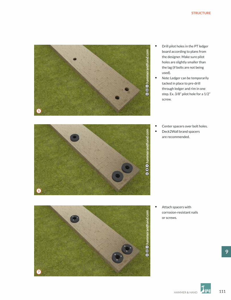
111
STRUCTURE
19
• center spacers over bolt holes.
• Deck2Wall brand spacers
are recommended.
• Drill pilot holes in the PT ledger
board according to plans from
the designer. Make sure pilot
holes are slightly smaller than
the lag (if bolts are not being
used).
• Note: Ledger can be temporarily
tacked in place to pre-drill
through ledger and rim in one
step. ex. 3/8” pilot hole for a 1/2”
screw.
• Attach spacers with
corrosion-resistant nails
or screws.
5
6
7

112
STRUCTURE
9
• Attach joist hangers over top of FastFlashed
ledger board.
• FastFlash around the ends of the joists before setting
into joist hangers.
• Dab a generous amount of FastFlash in and over
the pilot holes in the sheathing and rim joist before
attaching ledger board to prevent moisture intrusion.
• Bolt on PT ledger board.
• Install flashing above ledger board. cut slots where
joists intersect with flashing and bend the leg straight
along the top of the joist. Hammer flat.
• Bead and tool Joint & Seam Filler over top of sheet
metal flashing leg for a continuous drainage plane.
8 9
10 11

113
STRUCTURE
19
• Attach decking.
• Replace necessary siding, allowing for a 1 - 2” gap above flashing to prevent
water damage to cladding.
1” MIN. GAP
12

114
STRUCTURE
9
Hardware
Options
• Johnson hardware: 200sd commercial grade with 200 series door hanger and hanger plate.
• Ducasse: Many options.
• Sugatsume: Many options.
• Hafele: Many options.
For situations where wall framing is limited to 3 1/2” (not recommended) the Johnson Pocket Door Kit can be used
(2700 Pre-Assembled Pocket Door Frame). Do not use the assembly required steel stud Pocket Door Kit.
a
B
9.2 PocKeT DooR FRAMING
A. Studs at pocket to be engineered lumber or heavy gauge steel studs to provide rigidity to wall panel.
B. create rabbet in door jamb by installing additional trim to receive the door and provide complete closure.

115
STRUCTURE
19
Top of stairs
Bottom of stairs
Note: This is for hemmed in stairs. If the staircase is floating, the strongback would be against the inside wall.
a
B
C
9.3 STAIR FRAMING
A. STRINGeRS ARe FRoM eNGINeeReD MATeRIAL (LVL PReFeRReD)B. 3/4 PLYWooD HANGeR PLATec. STRoNGBAcK (2 x 4 oR SIMILAR)

116
ABBReVIATIoN MeANING
Ac Air conditioning
DHW Domestic Hot Water
ecM electrically commutated Motor
ePDM ethylene Propylene Diene Monomer
ePS expanded Polystyrene
FAF Fluid Applied Flashing
H&H Hammer And Hand
HPA Health Protection Agency
HRV Heat Recovery Agency
HSPF Heating Seasonal Performance Factor
HVA Heating Ventilation And Air conditioning
Ic-RATING Insulation contact Rating
IcAT High Performance Insulation contact Rating
KD Kiln Dried
MDF Medium-Density Fiberboard
oc on center
oSHA occupational Safety And Health Administration
PT Pressure Treated
PoLYISo Polyisocyanurate Insulation
qAP quality Assurance Program
Ro Rough opening
RRP Renovation, Repair, And Painting
S-DRIeD Standing Dried
SeeR Seasonal energy efficiency Ratio
RIGID PANeL Rigid Material Layer
STD-BTR Standard or Better
TPo Single Ply Roofing Material
WRB Water-Resistive Barrier
xPS extruded Polystyrene
aBBReVIaTIONs & DeFINITIONs

117
aCKNOWleDGemeNTs
THANK YoU
Many hands were involved in the production of this manual. From the building experts penning the pages
to the illustrators creating the details, each person involved helped bring this manual from conversations in hallways to
the detailed manual you are reading now.
authors
Sam Hagerman
Skylar Swinford
Dan Whitmore
MAc casares
Zack Semke
Production
Laura Grange
Shane Leaman
Samantha Gatzke
Ryan Tyni
Ashley Anderson
Krista Dorsey
Dexter Hagerman
