beta and gamma correction factors for the eberline … beta and gamma correction factors for the...
TRANSCRIPT
PNNL-13603 Beta and Gamma Correction Factors for the Eberline RO-20 Ionization Chamber Survey Instrument
M. L. Johnson B. A. Rathbone T. E. Bratvold
August 2001
Prepared for the Lockheed Martin Services, Inc. under Contract DE-AC06-760RL01830


PNNL-13603 Beta and Gamma Correction Factors for the Eberline RO-20 Ionization Chamber Survey Instrument
M. L. Johnson B. A. Rathbone T. E. Bratvold
August 2001
Prepared for the Lockheed Martin Services, Inc. under Contract DE-AC06-760RL01830

Page 4 of 22
INTRODUCTION This technical document provides details of derived correction factors for the Eberline RO-20 (1995) survey meter, which uses an ionization chamber to measure ambient exposure rates. A thin end window allows the instrument to measure exposure rates from non-penetrating radiation (i.e., beta radiation). Correction factors are provided for contact measurements with beta and gamma disk sources, gamma beams and, finally, general area beta fields. Beta correction factors are based on the instrument�s response to 204Tl, selected as the most conservative isotope for beta correction factors, as indicated in previous studies of similar instruments using 204Tl, 147Pm, and 90Sr(Y) isotopes (Hankins 1982). Gamma correction factors are based on 137Cs, considered the predominant source of gamma radiation on the Hanford Site. SUMMARY Correction factors developed for the Eberline RO-20 are summarized in the following tables. Each correction factor type (disk source, beam source, or general area beta) is detailed in the following sections. Gamma disk source correction factors adjust the instrument�s response to the true dose rate at the surface of (on contact with) the source. The beta disk source correction factors adjust the instrument�s response to the true dose rate either at the source surface or at 1/8 inch from the source surface. Both beam and general area beta correction factors correct the instrument�s response to the true dose rate at the center of the instrument�s ion chamber. The correction factor calculated for general area beta exposure rates is two (2) rad/h per R/h. Tables 1 and 2 summarize the correction factors for disk and beam sources.

Page 5 of 22
Table 1. Eberline RO-20 Gamma and Beta Disk Source Correction Factors
Correction Factor for Contact Measurements(1)
For exposure rate on contact with source
For exposure rate at 1/8 inch from source Disc
Diameter Beta(2)
(rad/h / R/h ± 1σ) Gamma(3)
(R/h / R/h ± 1σ) Beta(4)
(rad/h / R/h ± 1σ) 0.5 in 250 ± 40 54 ± 1 180 ± 9 1 in 46 ± 4 26 ± 3 55 ± 13 2 in 15 ± 12 8 ± 1 13 ± 2 3 in 6 ± 2 5 ± 2 6 ± 1
(1) Correction factor is the ratio of the true dose rate (at the point the dose rate was measured) to the
instrument�s response rate. (2) Instrument response rate is measured with the source�s surface on the same plane as the rails that hold
the instrument�s beta window (~10 mm (3/8 inches) from instrument window). Dose rate is measured at the surface of (in contact with) the source. Beta correction factors are based on 204Tl.
(3) Gamma correction factors are based on 137Cs; the source is in contact with the beta shield. (4) Instrument response rate is measured with the source surface on the same plane as the rails that hold the
instrument�s beta window. Dose rate is measured 1/8 inch from the surface of the source. Table 2. Eberline RO-20 Beam Correction Factors
Gamma Beams (R/h / R/h) (1)
Beam Diameter, inches
Beam perpendicular to chamber
Beam coaxial with chamber
< 0.50 97 129 0.50 24 32 0.75 11 14 1.00 6 8 1.50 3 4 2.00 2 2
≥ 3.00 1 1 1. Instrument window is closed; correction factor corrects instrument�s response to true
exposure rate at the center of the chamber. Gamma beam correction factors are calculated as the ratio of the chamber volume to the ionization volume.

Page 6 of 22
INSTRUMENT DESCRIPTION An Eberline RO-20 ionization chamber, a box-shaped ion chamber used to measure exposure rates in air, was the instrument tested. The ionization chamber measures 2.84 inches in diameter by 2.14 inches in height for a total volume of 13.5 in3. The chamber has a sidewall aerial density of 1,000 mg/cm2. The thin beta window is composed of two layers of aluminized polycarbonate and has a total aerial density of 7 mg/cm2. DEFINITION OF “CORRECTION FACTOR” Correction factors provided in this report adjust the instrument response to the true exposure rate, either: - On contact with the source (for beta and gamma disk sources), at 1/8 inch from the source
(for beta disk sources only), or - At the center of the ion chamber (for beam measurements and for general area beta
measurements). ! Beta correction factors for contact measurements with disk sources correct the instrument�s
response with the window 10 mm from the source to the true exposure rate on contact with the source or at 1/8 inch from the source.
! Beta correction factors for general area beta measurements correct the instrument�s response
to the true exposure rate at the center of the ion chamber.
! Gamma correction factors for contact measurements with disk sources correct the instrument�s response with the beta shield in contact with the source (i.e., the window closed and in contact with the source surface) to the true exposure rate on contact with the source.
! Gamma beam correction factors correct the instrument�s response to the true exposure rate at
the center of the ion chamber. Previously developed correction factors for contact measurements with the Eberline RO-3B (1984) corrected the instrument�s response to the true exposure rate at the window of the instrument. When the instrument is in contact with the source, the window is at some, albeit small, distance from the source. Eberline RO-20 beta correction factors are larger than the previously reported Eberline RO-3B correction factors, despite the fact that the RO-20 chamber is smaller than the RO-3B chamber. The reason for higher correction factors is that contact correction factors are based on the contact dose rate with the source. Previous correction factors were based on the exposure rate at some distance from the source (such as at the instrument�s window). In addition, the beta isotope, upon which previously reported RO-3B beta correction factors are based, is not known and may have been 90Sr(Y). Beta correction factors in this report are based on 204Tl, which emits a lower energy beta.

Page 7 of 22
DISK SOURCE CORRECTION FACTORS Correction factors were developed for thick-windowed 137Cs disk sources and thin-windowed 204Tl disk sources. The 137Cs sources provide gamma geometry correction factors; the 204Tl disk sources provided a basis for beta geometry correction factors. The correction factors adjust the instrument�s response in R/h to the true exposure rate in R/h for gamma sources, or the true shallow dose rate in tissue in rad/h for beta sources (i.e., the correction factor units are R/h per R/h or are rad/h per R/h). The first step in developing the disk source correction factors was measuring the true exposure or dose rate from each disk source. The second step was to measure the Eberline RO-20�s response to each source. Finally, a correction factor was calculated using the ratio of the true exposure or dose rate to the instrument�s response. Rather than model the disk sources as a series of point sources, 137Cs and 204Tl disk sources were purchased that had physical dimensions matching the disk sources of interest to this project. The disk sources, purchased from Amersham(1), had active areas with 12 mm, 25 mm, 50 mm, and 75 mm diameters. All sources had nominal activity of 150 kBq (4 µCi). Actual activities varied from 147 kBq to 153 kBq. Thin, chipstrate thermoluminescent dosimeters (TLD�s) were used to measure the exposure or dose rate from each disk source. Measuring the Exposure Rate from 137Cs Disk Sources The true exposure rate produced by each gamma disk source was determined using chipstrate TLDs mounted in 7 mg/cm2 covers. The chipstrates were placed on polyethylene blocks measuring approximately 4 inches high by 3.5 inches wide by 1 inch thick. The polyethylene block with TLD�s mounted to its front face was placed at some measured distance from the source surface. Total exposure time, typically greater than 4 hours, was recorded. Background TLD�s were processed along with the exposed TLDs. Total exposure recorded by background TLD�s was subtracted from the total exposure recorded on exposed TLDs. The chipstrate reader was calibrated using chipstrates mounted on identical phantoms and exposed to 1 R 137Cs at a distance of one meter. The chip readings in units of R were taken to be a measure of the true exposure rate. Because only gamma radiation was involved, corrections for angular dependence were assumed negligible. Measuring the Shallow Dose Rate from 204Tl Disk Sources The true shallow dose rate produced by each beta disk source in the specified geometry was determined using chipstrate TLDs mounted on polyethylene blocks as described above and the reader was calibrated as described above. For the purpose of converting from TLD units of exposure to TLD units of absorbed dose in tissue, a conversion factor of 1 R = 1 rad was used.
(1) Nycomed Amersham, United Kingdom
Page 8 of 22
This is not unreasonable given that the Cx factors between 0.98 and 1.03 are given for 137Cs in the performance test standards used for extremity and whole body dosimetry at DOE facilities (DOE 1986, HPS 1995). Beta Correction Factors for 204Tl Chipstrate Exposures The 204Tl chip results were corrected for beta energy dependence. Correction factors were estimated using VARSKIN MOD2®2, a computer program that calculates shallow dose rates in tissue due to beta sources. All Amersham sources used for irradiation had frontal areas greater than 10 times the frontal area of the TLD chip (0.1 cm2), and appeared much like infinite sources to the TLD chip when in close proximity. Consequently, when using VARSKIN MOD2® to estimate the appropriate 204Tl beta correction factor for use with the chipstrate in contact geometry, a disk source of large dimensions (11.28 cm diameter) relative to the chip (0.32 cm x 0.32 cm x 0.015 cm) was chosen as the model. The assumption that the source appeared as an infinite slab was confirmed by repeated calculations using the actual source sizes. The computer code VARSKIN MOD2® was used to calculate the volume averaged dose to a volume of skin with a frontal area 0.1 cm2 and lying at depths between 6.9 and 7.1 mg/cm2 and to a volume of TLD material having a frontal area of 0.1 cm2 and lying between 7.0 and 47.0 mg/cm2 depths. The source was modeled as a two dimensional 204Tl disk source 100 cm2 in area (11.28 cm dia.) with no covering. The distance between the source and targets was given as 0.1 mm (contact). The chip�s beta correction factor was calculated as the volume averaged dose to the chip divided by the volume averaged dose to a patch of skin of the same frontal area. This correction factor includes the geometry effects from beta particles striking at an angle from the source�s periphery. At a distance of 0.1 mm (contact), the results show that the volume averaged dose received by the skin at the same location and with the same area as the chip, is 1.98 times the volume averaged dose received by the chip. The total correction factor by which chip readings in R were multiplied to get actual shallow dose in rad from disk sources was rounded to 2.0. Measuring the RO-20 Response to the Disk Sources Once the true exposure or dose rate from each source was known, the next step was to determine the response of the instruments to each of the disk sources. To allow a more accurate measurement of the instrument response, an electrometer was placed in-line with the meter circuit to measure the current delivered to the meter. This eliminated errors associated with reading the instrument�s analog display. The correlation between meter current and exposure rate was determined by repeating the (b) VARSKIN MOD2® was developed by JS Durham at Pacific Northwest National Laboratory and documented in
NUREG/CR-5873 (PNL 7913).

Page 9 of 22
measurements in known radiation fields. Two points on each range of the instrument were measured using 137Cs calibration fields. Each data point represents an average of 20 separate electrometer readings. The RO-20�s response was measured with disk sources as close as possible to the detector. For the RO-20 beta source measurements, the actual source to window distance was limited by the rails used to guide the beta shield, (~ 10 mm). For gamma source measurements, the RO-20 window was closed and the gamma sources were in contact with the beta shield (~ 10 mm from the beta window). To compare the methodology used in this report for calculating correction factors with the methodology used in previous years at the Hanford Site, instrument response data was also collected for the Eberline RO-3B. This allowed the author to compare newly calculated correction factors for the Eberline RO-3B with correction factors developed many years ago. Eberline RO-3B beta source measurements were made with beta source on the same plane as the retaining ring that holds the thin beta window (source was approximately 2.4 mm from the beta window). Gamma source measurements were also made with the instrument window closed and the source in contact with the beta filter. Calculation of Correction Factor for Disk Sources Once the true exposure rate and instrument response for each source was known, the correction factor was calculated as a ratio of the true exposure rate (R/h or rad/h) to the instrument�s response rate (R/h). Error bars for the beta correction factors were likely due to non-uniformities in the distribution of the source activity. Multiple measurements of each source, with the TLD in contact with the source, resulted in wide and varied estimates of contact dose rates. More consistent data with smaller error bars was obtained with TLD�s at 1/8 inch from the surface of the source. Consequently, two sets of correction factors are presented for the beta sources. One set corrects the RO-20 response to the true dose rate on contact with (physically touching) the surface of the source. The second set corrects the RO-20 response to the true dose rate 1/8 inch from the surface of the source. In both cases, the RO-20 to source geometry is identical (i.e., the source is on the same plane as the rails that hold the RO-20 beta shield). A summary of the TLD results, and instrument response data, is provided in Attachment 1, along with calculated correction factors reiterated in Table 1.

Page 10 of 22
Table 1. Gamma and Beta Disk Source Correction Factors for the Eberline RO-20.
Correction Factor for Contact Measurements(1) For exposure rate on contact with source
For exposure rate at 1/8 inch from source
Disc Diameter Beta (2)
(rad/h / R/h ± 1σ) Gamma (3)
(R/h / R/h ± 1σ) Beta (4)
(rad/h / R/h ± 1σ)
0.5 in 250 ± 40 54 ± 1 180 ± 9 1.0 in 46 ± 4 26 ± 3 55 ± 13 2.0 in 15 ± 12 8 ± 1 13 ± 2 3.0 in 6 ± 2 5 ± 2 6 ± 1
(1) Correction factor is the ratio of the true dose rate (at the point the dose rate was measured) to the
instrument�s response. (2) Instrument response is measured with the source surface on same plane as rails that hold the instrument
beta window (~10 mm (3/8 inches) from instrument window). Dose rate is measured at the surface of (in contact with) the source. Beta correction factors based on 204Tl.
(3) Gamma correction factors based on 137Cs; source is in contact with the beta shield. (4) Instrument response is measured with the source surface on same plane as rails that hold the instrument
beta window. Dose rate is measured 1/8 inch from the surface of the source. GAMMA BEAMS An ionization chamber�s response to a beam of gamma radiation must be corrected to account for the partial ionization of the chamber. The correction factor is calculated as the ratio of the total ionization chamber volume to the irradiated volume. The ionization chamber is essentially a right cylinder, the volume of which is readily calculated. The beam is assumed to vertically intersect the axis of the chamber. For the purposes of this report, the beam is assumed to irradiate an area within the chamber that can be represented by a right cylinder. This is not entirely accurate as the ends of the cylinder are curved (to match the curvature of the chamber sidewall) but is sufficiently accurate for this purpose. The calculated beam correction factors are listed in Table 2; a copy of the spreadsheet is provided in Attachment 2. Beam correction factors were calculated for beams perpendicular to the chamber and for beams coaxial with the chamber. The axis of beams perpendicular to the chamber must intersect the axis of the chamber.

Page 11 of 22
Table 2. Eberline RO-20 Beam Correction Factors
Gamma Beams (R/h / R/h)(1)
Beam Diameter, inches
Beam perpendicular to chamber
Beam coaxial with chamber
< 0.50 97 129 0.50 24 32 0.75 11 14 1.00 6 8 1.50 3 4 2.00 2 2
≥ 3.00 1 1 (1) Instrument window is closed; correction factor corrects instrument�s response to true
exposure rate at the center of the chamber. Gamma beam correction factors are calculated as the ratio of the chamber volume to the ionization volume.
GENERAL BETA FIELDS The Eberline RO-20 correction factor for uniform beta fields was estimated using a 204Tl point source. The center of the RO-20 ion chamber was placed 35 cm from the source. At this distance, the 204Tl source appears as a uniform field to the instrument. The response of the RO-20 was 700 mrad/h with an actual dose rate (measured with an extrapolation chamber) measuring 1.34 R/h. This yields a correction factor of 1.9, which for the purposes of this study was rounded to 2 rad/h per R/h. Similarly, the Eberline RO-20 response was measured for a uniform 90Sr(Y) field by placing the center of the RO-20 30 cm from a 50 mCi 90Sr(Y) point source. The delivered shallow dose rate was 20 rad/h. The instrument response was 19 R/h, yielding a correction factor of approximately one rad/h per R/h.

Page 12 of 22
REFERENCES Department of Energy. 1986. Department of Energy Standard for the Performance Testing of Personnel Dosimetry Systems. DOE, Washington. Eberline Instrument Corporation. 1995. RO-20 Ion Chamber Technical Manual, Santa Fe, NM. Eberline Instrument Corporation. 1984. Technical Manual for Ion Chamber Model RO-3B. Santa Fe, NM. Hankins, D.E. 1982. Beta-Energy Response of the Eberline RO-7 Survey Instrument. Lawrence Livermore National Laboratory, Livermore, CA. Health Physics Society. 1995. Performance Testing of Extremity Dosimeters, HPS N13.32-1995. Health Physics Society, McLean VA.
Attachment 1
Data Sheets for Calculating Disk Source Correction Factors

Page 14 of 22
Numbers in this Isotope: 204Tl Beta column Dist. appear to TLD Minimum TLD Dose RO-20 in Rpt.
Source SN, Diameter, Src. Exposure
Time Exposure Total Exposure Rate Response Correction TLD # and isotope (in.) Hour Min Time, min Time mR mrad/h (1) mR/h Factor D13837 Background TLD NA NA NA 0 D15413 Background TLD NA -4 D12947 Background TLD NA -1 D19219 Background TLD NA 2 D11309 Background TLD NA 0 D16623 Background TLD NA NA NA 16 D15746 Background TLD NA NA NA 2 D14271 Tl-204 SN FN 411 0 0 20 20 20 min 7288 43381 D19586 12 mm diameter 0 20 20 min 3947 23494 D10047 149 kBq 0 20 20 min 5091 30304 D12833 0 20 2771 16494 Average 28418 104 273 Std. Dev 11458 error +/- 110 D15284 Tl-204 SN FN 411 0 10 2315 27560 D15408 12 mm diameter 0 10 2937 34964 D25256 149 kBq 0 10 2546 30310 D13052 0 10.06667 2137 25272 D23165 0 10 2065 24583 D13180 0 11 2157 23344 D13006 0 10 2180 25952 D13514 0 10 1753 20869 D15280 0 10 2008 23905 D26047 0 10 1825 21726 D14107 0 10 2151 25607 D10237 0 10.05 20 min 2215 26238 Average 25861 104 249 Std. Dev 3813 error +/- 37
D12243 12 mm
CP Window (0.1) 21 20 min 4344 24626
D19494 12 mm
CP Window (0.1) 24 20 min 4244 21052
D11048 12 mm
CP Window (0.1) 20.4 20 min 3558 20763
Average 22147 104 213 Std. Dev 2152 error +/- 21

Page 15 of 22
Numbers in this Isotope: 204Tl Beta column Dist. appear to TLD Minimum TLD Dose RO-20 in Rpt.
Source SN, Diameter, Src. Exposure
Time Exposure Total Exposure Rate Response Correction TLD # and isotope (in.) Hour Min Time, min Time mR mrad/h (1) mR/h Factor D16414 12 mm 0.125 20 20 min 3032 18048 D12329 12 mm 0.125 22.5 20 min 3551 18788 D17825 12 mm 0.125 20 20 min 3332 19833 Average 18890 104 182 Std. Dev 897 error +/- 9 D20754 12 mm 0.25 20 20 min 1341 7982 D11146 12 mm 0.25 20 20 min 1434 8536 D12765 12 mm 0.25 20 20 min 1463 8708 Average 8409 104 81 Std. Dev 379 error +/- 4 D13955 12 mm 0.5 0 30 30 30 min 681 2702 104 26 error +/- D21555 12 mm 1 2 0.5 120.5 2 hr 677 669 104 6 error +/- D10718 12 mm 1.5 4 30 270 4.5 hr 686 188 104 2 error +/- D14178 Tl-204 SN FN 412 0 0 20 20 20 min 135 804 D11532 25 mm diameter 0 20 20 min 269 1601 D15178 151 kBq 0 20 20 min 399 2375 D13988 0 20 20 min 199 1185 D10939 0 40 40 676 2012 D25463 0 40 40 4031 11997 D19527 0 41 41 1726 5012 D25523 0 65 65 6045 11071 D16329 0 60 60 5854 11615 D10048 0 114 11624 12139 (this set not used) Average 5981 104 58 Std. Dev. 5060 error +/- 49 D18209 Tl-204 SN FN 412 0 20 876 5214 D10221 25 mm diameter 0 20 834 4964 D17285 151 kBq 0 20 700 4167 D18087 0 20 773 4601 Average 4737 104 46 Std. Dev. 456 error +/- 4

Page 16 of 22
Numbers in this Isotope: 204Tl Beta column Dist. appear to TLD Minimum TLD Dose RO-20 in Rpt.
Source SN, Diameter, Src. Exposure
Time Exposure Total Exposure Rate Response Correction TLD # and isotope (in.) Hour Min Time, min Time mR mrad/h (1) mR/h Factor D11364 Tl-204 SN FN 412 0.125 60 45 min 2401 4764 D16143 25 mm diameter 0.125 22 20 min 987 5341 D18237 151 kBq 0.125 32 20 min 2063 7675 D12064 0.125 32 20 min 1392 5179 Average 5740 104 55 Std. Dev. 1313 error +/- 13 D14635 Tl-204 SN FN 412 0.5 45 45 min 703 1860 D22726 25 mm diameter 0.5 20 20 min 305 1815 D10395 151 kBq 0.5 20 20 min 332 1976 D12371 0.5 20 20 min 326 1940 Average 1898 104 18 Std. Dev. 73 error +/- 1 D22717 25 mm 1 122 2 hr 845 825 D12312 25 mm 1.5 270 4.5 hr 662 181 D16183 Tl-204 SN FN 413 0 30 30 min 819 3250 D25560 50 mm diameter 0 30 30 min 480 1905 D14360 147 kBq 0 30 564 2238 D19173 0 34 761 2665 D11172 0 34 26 91 D13945 0 34 132 462 D25422 0 31 29 111 D19394 0 31 135 518 D19247 0 31 225 864 D25972 0 28 26 111 D19572 0 28 581 2470 D12450 0 28 30 min 409 1739 Average 1369 94 15 Std. Dev. 1136 error +/- 12 D16015 Tl-204 SN FN 413 0.125 32 80 min 335 1246 D12015 50 mm diameter 0.125 32 80 min 256 952 D12146 147 kBq 0.125 32 406 1510 D11765 0.125 31 293 1125 D13933 0.125 31 307 1179 80 min Average 1203 94 13 Std. Dev. 204 error +/- 2

Page 17 of 22
Numbers in this Isotope: 204Tl Beta column Dist. appear to TLD Minimum TLD Dose RO-20 in Rpt.
Source SN, Diameter, Src. Exposure
Time Exposure Total Exposure Rate Response Correction TLD # and isotope (in.) Hour Min Time, min Time mR mrad/h (1) mR/h Factor D15988 50 mm 0.5 82 80 min 610 886 D13232 0.5 82 80 min 641 931 D12050 0.5 82 80 min 482 700 Average 839 94 9 Std. Dev. 122 error +/- 1 D20747 50 mm 1 180 3 hr 566 374 D15977 1 180 3 hr 545 360 D12560 1 180 3 hr 526 348 Average 361 94 4 Std. Dev. 13 error +/- 0 D16533 50 mm 1.5 280 4.5 hr 639 168 D13667 1.5 280 4.5 hr 508 134 D22821 1.5 280 4.5 hr 592 156 Average 153 94 2 Std. Dev. 17 error +/- 0 D12605 Tl-204 SN FN 414 0 61 1 hour 345 673 D15720 75 mm diameter 0 61 1 hour 199 388 D10800 146 kBq 0 61 1 hour 153 299 D14070 0 61 1 hour 246 480 D25776 0 61 1 hour 207 404 Average 449 80 6 Std. Dev. 141 error +/- 2 D19562 Tl-204 SN FN 414 0.125 50 4.5 hr 195 464 D22846 75 mm diameter 0.125 50 236 562 D18202 146 kBq 0.125 50 251 598 D11071 0.125 50 227 540 D15700 0.125 50 171 407 D18973 0.125 50 216 514 D18192 0.125 50 189 450 D10844 0.125 45 179 474 D15722 0.125 45 160 423 D11053 0.125 45 194 513 D10701 0.125 45 202 534 D19699 0.125 45 199 526 D11917 0.125 54 242 534 D23104 0.125 54 226 498 D18233 0.125 54 210 463

Page 18 of 22
Numbers in this Isotope: 204Tl Beta column Dist. appear to TLD Minimum TLD Dose RO-20 in Rpt.
Source SN, Diameter, Src. Exposure
Time Exposure Total Exposure Rate Response Correction TLD # and isotope (in.) Hour Min Time, min Time mR mrad/h (1) mR/h Factor D19542 0.125 54 205 452 D16666 0.125 54 219 483 D23101 0.125 54 4.5 hr 289 637 4.5 hr Average 504 80 6 Std. Dev. 59 error +/- 0.74 D22878 Tl-204 SN FN 414 0.5 120 2 hr 321 318 D15913 75 mm diameter 0.5 120 2 hr 415 412 D12469 146 kBq 0.5 120 2 hr 248 246 D12417 0.5 120 2 hr 265 263 D19528 0.5 120 2 hr 326 323 Average 313 80 4 Std. Dev. 65 error +/- 1 D15613 Tl-204 SN FN 414 1 180 3 hr 280 185 D16679 75 mm diameter 1 180 3 hr 413 273 D15407 146 kBq 1 180 3 hr 296 196 D18199 1 180 3 hr 280 185 D15019 1 180 3 hr 241 159 Average 200 80 2 Std. Dev. 43 error +/- 1 D13162 Tl-204 SN FN 414 1.5 300 5 hr 309 76 D18805 75 mm diameter 1.5 300 5 hr 431 106 D20478 146 kBq 1.5 300 5 hr 310 76 D16067 1.5 300 5 hr 319 78 D16569 1.5 300 5 hr 314 77 Average 83 80 1 Std. Dev. 13 error +/- 0 NOTES 1. Dose rate is the total dose divided by the exposure time (in hours) and multiplied by the correction factor. RO-20 Correction Factor Study
Data sheet for measuring dose rate from disk sources with beta shield
Isotope: Cesium-137 Gamma Dist. to Minimum TLD Exposure RO-20
Source SN, Diameter, Src. Exposure Time Total Total Exposure Rate Response Correction
TLD # and isotope (in.) Hour Min Time, min Time mR mR/h mR/h Factor D20661 Background TLD NA NA NA 14 D11558 Background TLD NA NA NA
Page 19 of 22
Numbers in this Isotope: 204Tl Beta column Dist. appear to TLD Minimum TLD Dose RO-20 in Rpt.
Source SN, Diameter, Src. Exposure
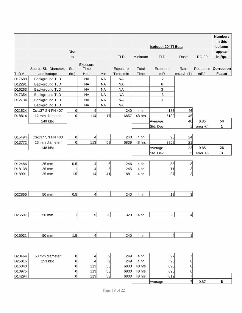
Time Exposure Total Exposure Rate Response Correction TLD # and isotope (in.) Hour Min Time, min Time mR mrad/h (1) mR/h Factor D17688 Background TLD NA NA NA -2 D12291 Background TLD NA NA NA 6 D16263 Background TLD NA NA NA 3 D17354 Background TLD NA NA NA -3 D12734 Background TLD NA NA NA -1 Background TLD NA NA NA D21524 Cs-137 SN FN 407 0 4 240 4 hr 185 46 D18814 12 mm diameter 0 114 17 6857 48 hrs 5182 45 149 kBq Average 46 0.85 54 Std. Dev 1 error +/- 1 D15494 Cs-137 SN FN 408 0 4 240 4 hr 95 24 D13772 25 mm diameter 0 113 59 6839 48 hrs 2358 21 148 kBq Average 22 0.85 26 Std. Dev 2 error +/- 3 D12486 25 mm 0.5 4 6 246 4 hr 33 8 D18138 25 mm 1 4 5 245 4 hr 11 3 D18991 25 mm 1.5 14 41 881 4 hr 37 3 D22866 50 mm 0.5 4 240 4 hr 13 3 D25597 50 mm 1 5 20 320 4 hr 20 4 D15031 50 mm 1.5 4 240 4 hr 4 1 D20464 50 mm diameter 0 4 9 249 4 hr 27 7 D25816 153 kBq 0 4 9 249 4 hr 25 6 D16348 0 113 53 6833 48 hrs 890 8 D10975 0 113 53 6833 48 hrs 696 6 D14294 0 113 53 6833 48 hrs 812 7 Average 7 0.87 8

Page 20 of 22
Numbers in this Isotope: 204Tl Beta column Dist. appear to TLD Minimum TLD Dose RO-20 in Rpt.
Source SN, Diameter, Src. Exposure
Time Exposure Total Exposure Rate Response Correction TLD # and isotope (in.) Hour Min Time, min Time mR mrad/h (1) mR/h Factor D10572 50 mm 0.5 4 0 240 4 hr 21 5 D20606 50 mm 0.5 4 0 240 4 hr 18 5 D12506 50 mm 0.5 4 0 240 4 hr 17 4 Average 5 D18360 50 mm 1 5 6 306 4 hr 9 2 D17738 50 mm 1 5 6 306 4 hr 9 2 D17561 50 mm 1 5 6 306 4 hr 17 3 Average 2 D25783 50 mm 1.5 4 0 240 4 hr 6 2 D20770 50 mm 1.5 4 0 240 4 hr 1 0 D22825 50 mm 1.5 4 0 240 4 hr 6 2 Average 1 D15018 Cs-137 SN FN 410 0 4 5 245 4 hr 35 9 D13382 75 mm diameter 0 4 5 245 4 hr 13 3 D16157 150 kBq 0 4 5 245 4 hr 12 3 D20700 0 4 5 245 4 hr 12 3 D10128 0 4 5 245 4 hr 11 3 D10985 0 113 50 6830 96 hrs 561 5 D13291 0 113 50 6830 96 hrs 634 6 D12490 0 113 50 6830 96 hrs 363 3 D15297 0 113 50 6830 96 hrs 439 4 D11119 0 113 50 6830 96 hrs 428 4 Average 4 0.78 5 D22815 75 mm 0.5 4 240 4 hr 11 3 D20483 75 mm 0.5 4 240 4 hr 4 1 D18155 75 mm 0.5 4 240 4 hr 5 1 D11380 75 mm 0.5 4 240 4 hr 11 3 D25481 75 mm 0.5 4 240 4 hr 4 1 Average 2 D25310 75 mm 1 4 1 241 4 hr 4 1 D19531 75 mm 1 4 1 241 4 hr 5 1 D12466 75 mm 1 4 1 241 4 hr 5 1 D15991 75 mm 1 4 1 241 4 hr 11 3 D18187 75 mm 1 4 1 241 4 hr 5 1 Average 1 D13567 75 mm 1.5 14 37 877 4 hr 16 1 D11013 75 mm 1.5 14 37 877 4 hr 17 1
Page 21 of 22
Numbers in this Isotope: 204Tl Beta column Dist. appear to TLD Minimum TLD Dose RO-20 in Rpt.
Source SN, Diameter, Src. Exposure
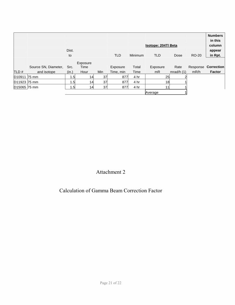
Time Exposure Total Exposure Rate Response Correction TLD # and isotope (in.) Hour Min Time, min Time mR mrad/h (1) mR/h Factor D10911 75 mm 1.5 14 37 877 4 hr 25 2 D11923 75 mm 1.5 14 37 877 4 hr 18 1 D15065 75 mm 1.5 14 37 877 4 hr 11 1 Average 1
Attachment 2
Calculation of Gamma Beam Correction Factor

Page 22 of 22
INSTRUMENT DIMENSIONS Distance
Eberline Source to Chamber Chamber Ion chamber Window, Volume Diameter, Depth, x-section
Model mm in3 cm3 inches in in2 RO-20 10.0 13.5 222 2.84 2.14 6.33 RO-3B 2.4 29.4 482 3.00 4.16 7.07
Notes: Diameter and depth verified with physical measurements for both instruments
CALCULATION OF BEAM CORRECTION FACTORS
RO-20 RO-3B RO-20 RO-20 RO-3B RO-3B Beam Beam Beam Beam Corr. Corr. Corr. Corr.
diameter X-section volume volume factor factor factor factor inches inches-sq perpen. perpen. perpen. coaxial perpen. coaxial
0.25 0.05 0.14 0.15 97 129 200 144 0.50 0.20 0.56 0.59 24 32 50 36 0.75 0.44 1.25 1.33 11 14 22 16 1.00 0.79 2.23 2.36 6 8 12 9 1.50 1.77 5.02 5.30 3 4 6 4 2.00 3.14 8.92 9.42 2 2 3 2 2.50 4.91 13.94 14.73 1 1 2 1 3.00 7.07 20.07 21.21 1 1 1 1 3.50 9.62 27.32 28.86 1 1 1 1 4.00 12.57 35.69 37.70 1 1 1 1