bfi vertical agitator - inoxpa.ru · installation, service and maintenance instructions bfi...
TRANSCRIPT

INSTALLATION, SERVICE AND MAINTENANCE INSTRUCTIONS
BFI VERTICAL AGITATOR
INOXPA, S.A. c/Telers, 54 Aptdo. 174
E-17820 Banyoles - Girona (Spain) Tel. : (34) 972 - 57 52 00 Fax. : (34) 972 - 57 55 02 Email: [email protected]
www.inoxpa.com
Original Manual 20.006.30.00EN
ED. 2012/02
EC declaration of conformity (according to Directive 2006/42/EC, annex II, part A)
Manufacturer: INOXPA, S.A.
C/ Telers, 54 17820 Banyoles (Girona) – SPAIN
Hereby declares, that the product:
VERTICAL AGITATOR BFI
Name Type
conforms to the specifications of the Council Directive: Machine Directive 2006/42/EC, and complies with the essential requirements of the Directive and Harmonised Standards: UNE-EN ISO 12100-1/2:2004 UNE-EN ISO 13857:2008 UNE-EN 953:1997 UNE-EN ISO 13732-1:2007 Low Voltage Directive 2006/95/CE (what repeal 73/23/EEC Directive), and conforms to UNE-EN 60204-1:2006 and UNE-EN 60034-1:2004 EMC Directive 2004/108/CE (what repeal 89/336/CEE Directive), and conforms to UNE-EN 60034-1:2004 In compliance with Regulations (CE) nº 1935/2004, relating to materials and articles intended to come into contact with foodstuff (repeal Directive 89/109/ECC), the materials in contact with the product do not transfer their components in quantities which may jeopardise consumer’s health.
Banyoles, 2012
Josep Mª Benet Technical manager
ED. 2012/02 1. Safety instructions BFI 1.1
1. Safety instructions.
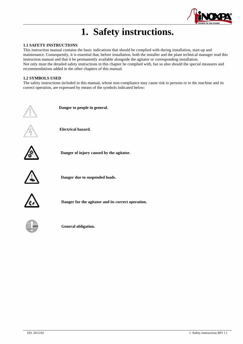
1.1 SAFETY INSTRUCTIONS This instruction manual contains the basic indications that should be complied with during installation, start-up and maintenance. Consequently, it is essential that, before installation, both the installer and the plant technical manager read this instruction manual and that it be permanently available alongside the agitator or corresponding installation. Not only must the detailed safety instructions in this chapter be complied with, but so also should the special measures and recommendations added in the other chapters of this manual. 1.2 SYMBOLS USED The safety instructions included in this manual, whose non-compliance may cause risk to persons or to the machine and its correct operation, are expressed by means of the symbols indicated below:
Danger to people in general. Electrical hazard.
Danger of injury caused by the agitator. Danger due to suspended loads. Danger for the agitator and its correct operation. General obligation.
1. Safety instructions BFI 1.2 ED. 2012/02
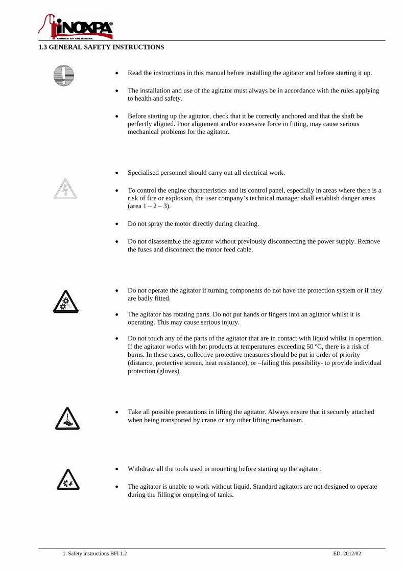
1.3 GENERAL SAFETY INSTRUCTIONS
• Read the instructions in this manual before installing the agitator and before starting it up. • The installation and use of the agitator must always be in accordance with the rules applying
to health and safety.
• Before starting up the agitator, check that it be correctly anchored and that the shaft be perfectly aligned. Poor alignment and/or excessive force in fitting, may cause serious mechanical problems for the agitator.
• Specialised personnel should carry out all electrical work. • To control the engine characteristics and its control panel, especially in areas where there is a
risk of fire or explosion, the user company’s technical manager shall establish danger areas (area 1 – 2 – 3).
• Do not spray the motor directly during cleaning. • Do not disassemble the agitator without previously disconnecting the power supply. Remove
the fuses and disconnect the motor feed cable.
• Do not operate the agitator if turning components do not have the protection system or if they are badly fitted.
• The agitator has rotating parts. Do not put hands or fingers into an agitator whilst it is
operating. This may cause serious injury. • Do not touch any of the parts of the agitator that are in contact with liquid whilst in operation.
If the agitator works with hot products at temperatures exceeding 50 ºC, there is a risk of burns. In these cases, collective protective measures should be put in order of priority (distance, protective screen, heat resistance), or –failing this possibility- to provide individual protection (gloves).
• Take all possible precautions in lifting the agitator. Always ensure that it securely attached when being transported by crane or any other lifting mechanism.
• Withdraw all the tools used in mounting before starting up the agitator.
• The agitator is unable to work without liquid. Standard agitators are not designed to operate during the filling or emptying of tanks.
ED. 2012/02 1. Safety instructions BFI 1.3
• Do not exceed the agitator’s maximum operating conditions. Do not modify the operating parameters that were initially set for the agitator without the prior written consent of INOXPA.
• The agitators and their installation may cause noise levels that exceed 85 dB (A) in some
unfavourable operating environments. In such cases, operators should wear hearing protection. 1.4 WARRANTY We wish to point out that any warranty issued will be null and void and that we are entitled to an indemnity for any civil liability claim for products which might be filed by third parties if:
operation and maintenance work has not been done following the corresponding instructions; the repairs have not been made by our personnel or have been made without our written authorization;
modifications are made to our material without prior written authorization; the parts or lubricants used are not original INOXPA parts/lubricants; the material has been improperly used due to error or negligence or have not been used according to the indications
and the intended purpose. all components subject to wear are excluded from the guarantee.
The General Delivery Terms which you have already received are also applicable. 1.5 INSTRUCTIONS MANUAL The information provided in the instruction manual refers to updated data. We reserve the right to modify the design and/or manufacturing specifications of our products as required, devoid of any obligation on our part to adapt any product supplied prior to such alteration. The technical information made available in this instruction manual, together with the graphs and technical specifications provided, shall continue to belong to us and should not be used (except for starting up this installation), copied, photocopied, made available or otherwise given to third parties without our prior written consent. INOXPA is reservation the right to modifying this instructions manual without previous notice. 1.6 INOXPA SERVICE
In the event of doubt or should you require a fuller explanation on particular data (adjustment, assembly, disassembly...), please do not hesitate to contact us.
ED. 2012/02 Index BFI
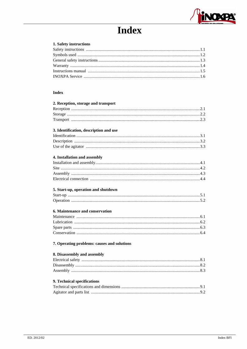
Index 1. Safety instructions Safety instructions ............................................................................................................. 1.1 Symbols used ..................................................................................................................... 1.2 General safety instructions ................................................................................................. 1.3 Warranty ............................................................................................................................ 1.4 Instructions manual ........................................................................................................... 1.5 INOXPA Service ............................................................................................................... 1.6
Index 2. Reception, storage and transport Reception ........................................................................................................................... 2.1 Storage ............................................................................................................................... 2.2 Transport ........................................................................................................................... 2.3 3. Identification, description and use Identification ...................................................................................................................... 3.1 Description ........................................................................................................................ 3.2 Use of the agitator ............................................................................................................. 3.3 4. Installation and assembly Installation and assembly .................................................................................................... 4.1 Site ..................................................................................................................................... 4.2 Assembly ........................................................................................................................... 4.3 Electrical connection ......................................................................................................... 4.4 5. Start-up, operation and shutdown Start-up .............................................................................................................................. 5.1 Operation ........................................................................................................................... 5.2 6. Maintenance and conservation Maintenance ...................................................................................................................... 6.1 Lubrication ........................................................................................................................ 6.2 Spare parts ......................................................................................................................... 6.3 Conservation ...................................................................................................................... 6.4 7. Operating problems: causes and solutions 8. Disassembly and assembly Electrical safety ................................................................................................................. 8.1 Disassembly ....................................................................................................................... 8.2 Assembly ........................................................................................................................... 8.3 9. Technical specifications Technical specifications and dimensions ........................................................................... 9.1 Agitator and parts list ........................................................................................................ 9.2
ED. 2012/02 2. Reception, storage and transport BFI 2.1
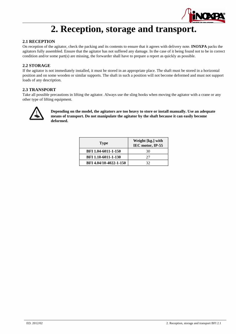
2. Reception, storage and transport. 2.1 RECEPTION On reception of the agitator, check the packing and its contents to ensure that it agrees with delivery note. INOXPA packs the agitators fully assembled. Ensure that the agitator has not suffered any damage. In the case of it being found not to be in correct condition and/or some part(s) are missing, the forwarder shall have to prepare a report as quickly as possible. 2.2 STORAGE If the agitator is not immediately installed, it must be stored in an appropriate place. The shaft must be stored in a horizontal position and on some wooden or similar supports. The shaft in such a position will not become deformed and must not support loads of any description. 2.3 TRANSPORT Take all possible precautions in lifting the agitator. Always use the sling hooks when moving the agitator with a crane or any other type of lifting equipment.
Depending on the model, the agitators are too heavy to store or install manually. Use an adequate means of transport. Do not manipulate the agitator by the shaft because it can easily become deformed.
Type Weight [kg.] with IEC motor, IP-55
BFI 1.04-6011-1-150 30 BFI 1.10-6011-1-130 27 BFI 4.04/10-4022-1-150 32
ED. 2012/02 3. Identification, description and use BFI 3.1
3. Identification, description and use.
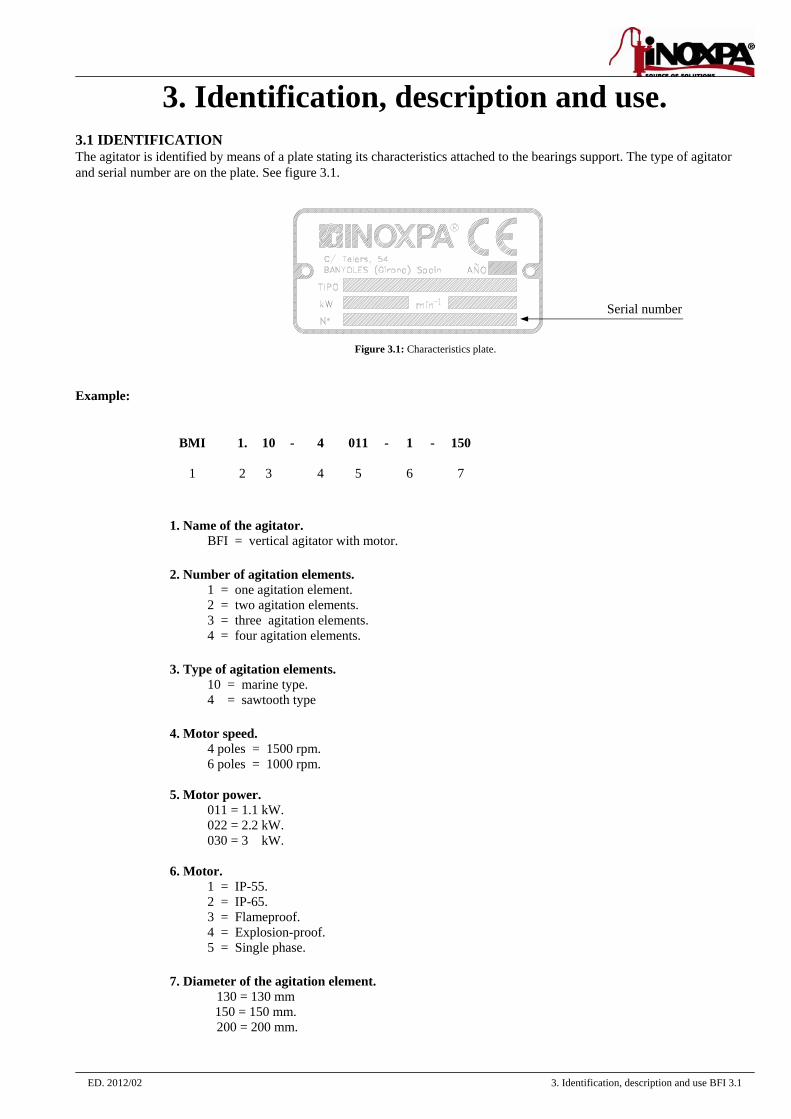
3.1 IDENTIFICATION The agitator is identified by means of a plate stating its characteristics attached to the bearings support. The type of agitator and serial number are on the plate. See figure 3.1.
Figure 3.1: Characteristics plate.
Example:
BMI 1. 10 - 4 011 - 1 - 150
1 2 3 4 5 6 7
1. Name of the agitator. BFI = vertical agitator with motor.
2. Number of agitation elements.
1 = one agitation element. 2 = two agitation elements. 3 = three agitation elements. 4 = four agitation elements.
3. Type of agitation elements.
10 = marine type. 4 = sawtooth type
4. Motor speed.
4 poles = 1500 rpm. 6 poles = 1000 rpm.
5. Motor power.
011 = 1.1 kW. 022 = 2.2 kW. 030 = 3 kW.
6. Motor. 1 = IP-55. 2 = IP-65. 3 = Flameproof. 4 = Explosion-proof. 5 = Single phase.
7. Diameter of the agitation element.
130 = 130 mm 150 = 150 mm. 200 = 200 mm.
Serial number

3. Identification, description and use BFI 3.2 ED. 2012/02
3.2 DESCRIPTION The BFI series range presents vertical agitators with direct motor, a stainless steel propeller and base and a double lip seal as sealing system for work under pressure or in vacuum. The motor size is standardised for all the models of the series. The agitator shaft is fixed onto the half shaft with a flange mount. Although these agitators are very compact, they have a bearing support which is totally independent of the motor. He half-shaft is guided by one or two bearings which withstand the thrust and radial force transmitted by the agitation element. All the parts that come into contact with the product are made of stainless steel, AISI-316 (1.4401) for agitator with a marine propeller and for those with sawtooth elements. It has an electropolished surface finish. The standard propellers are marine propeller (type 10) and sawtooth propeller (type 4). USE OF THE AGITATOR. They are used for mixing and blending processes in closed tanks with a 4000 litres of maximum volume and 1000 cPs. of maximum viscosity.
ED. 2012/02 4. Installation and assembly BFI 4.1
4. Installation and assembly
4.1 INSTALLATION AND ASSEMBLY If the agitator is supplied without a drive or other element, the purchaser shall be responsible for its assembly, installation, start-up and operation.
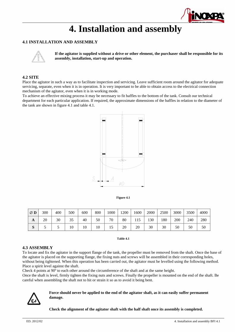
4.2 SITE Place the agitator in such a way as to facilitate inspection and servicing. Leave sufficient room around the agitator for adequate servicing, separate, even when it is in operation. It is very important to be able to obtain access to the electrical connection mechanism of the agitator, even when it is in working mode. To achieve an effective mixing process it may be necessary to fit baffles to the bottom of the tank. Consult our technical department for each particular application. If required, the approximate dimensions of the baffles in relation to the diameter of the tank are shown in figure 4.1 and table 4.1.
Figure 4.1
∅ D 300 400 500 600 800 1000 1200 1600 2000 2500 3000 3500 4000
A 20 30 35 40 50 70 80 115 130 180 200 240 280
S 5 5 10 10 10 15 20 20 30 30 50 50 50
Table 4.1
4.3 ASSEMBLY To locate and fix the agitator in the support flange of the tank, the propeller must be removed from the shaft. Once the base of the agitator is placed on the supporting flange, the fixing nuts and screws will be assembled in their corresponding holes, without being tightened. When this operation has been carried out, the agitator must be levelled using the following method. Place a spirit level against the shaft. Check 4 points at 90º to each other around the circumference of the shaft and at the same height. Once the shaft is level, firmly tighten the fixing nuts and screws. Finally the propeller is mounted on the end of the shaft. Be careful when assembling the shaft not to hit or strain it so as to avoid it being bent.
Force should never be applied to the end of the agitator shaft, as it can easily suffer permanent damage. Check the alignment of the agitator shaft with the half shaft once its assembly is completed.

4. Installation and assembly BFI 4.2 ED. 2012/02
4.5 ELECTRICAL CONNECTION Before connecting the electric motor to the mains, check the local regulations and the corresponding standards regarding electrical safety. Take special account of those parts referring to command and control of the agitator. Check the manufacturer’s instruction manual of the motor for connecting it to the mains.
Let the electrical connection of the motors to qualified personnel. Take the necessary measures in order to prevent any type of breakdown.
The motor should be protected with devices against overload and short-circuits.
It is not possible to use the agitator in areas of risk of fire or explosion if this has not been included in the order. Risk areas (zones 1 -2 - 3).
ED. 2012/02 5. Start-up, operation and shutdown BFI 5.1
5. Start-up, operation and shutdown
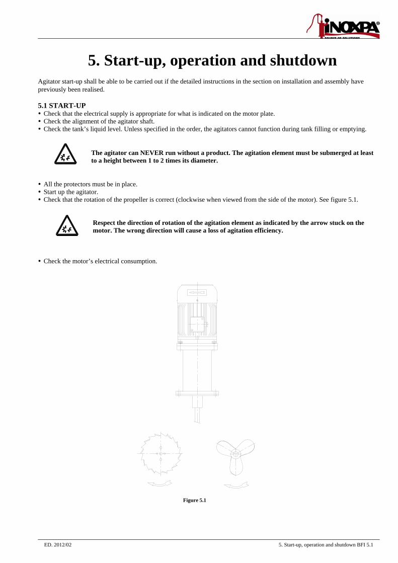
Agitator start-up shall be able to be carried out if the detailed instructions in the section on installation and assembly have previously been realised. 5.1 START-UP Check that the electrical supply is appropriate for what is indicated on the motor plate. Check the alignment of the agitator shaft. Check the tank’s liquid level. Unless specified in the order, the agitators cannot function during tank filling or emptying.
The agitator can NEVER run without a product. The agitation element must be submerged at least to a height between 1 to 2 times its diameter.
All the protectors must be in place. Start up the agitator. Check that the rotation of the propeller is correct (clockwise when viewed from the side of the motor). See figure 5.1.
Respect the direction of rotation of the agitation element as indicated by the arrow stuck on the motor. The wrong direction will cause a loss of agitation efficiency.
Check the motor’s electrical consumption.
Figure 5.1
5. Start-up, operation and shutdown BFI 5.2 ED. 2012/02
5.2 OPERATION
Do not modify the operating parameters for which the agitator was initially selected without prior written consent of INOXPA. (Risk of deterioration and danger for the user). Follow the operating instructions and safety indications described in the instructions manual of the tank on which the agitator is mounted. Mechanical hazards (drag, shearing, cutting, strike, squashing, clipping. etc.). If the agitation element is accessible from above or at the man way of the tank then the user is exposed to the aforementioned hazards.
The tank should be equipped with protection devices and safety equipment. Check the manufacturer’s instructions manual.
The introduction of a solid object or raw material may cause breakage of the agitation element or the breakage of other mechanical parts and endanger safety.
ED. 2012/02 6. Maintenance and conservation BFI 6.1
6. Maintenance and conservation
Maintenance work can only be carried out by qualified personnel that are trained and equipped with the necessary resources to carrying out this work. Before beginning maintenance work, ensure that the electric motor is disconnected and that the tank is empty.
6.1 MAINTENANCE Inspect the agitator regularly. Do not fail to keep the agitator clean. Check the state of the gearbox and motor. Check the state of the bearings. Check the sealing: lip seal.
Gearbox and motor maintenance shall be carried out in accordance with the manufacturer’s instructions. See the instructions manual. 6.2 LUBRICATION The vertical agitators of the BFI models are supported on permanently lubricated bearings, which means maintenance is not required. The bearings can be re-greased disassembling the support, cleaning thoroughly to remove the old grease or changing them as well as the bearing housings and, finally, applying new grease at 50-70%. When re-greasing, use only special grease for ball bearings with the following properties: Lithium-based or made up of high quality lithium. Viscosity 100 - 140 cSt at 40 ºC. Consistency NLGI grade 2 or 3. Continuous work temperature - 30 ºC to + 120 ºC.
The greasing of the gearbox / motor bearings shall be carried out in accordance with the manufacturer’s instructions. 6.3 SPARE PARTS To order spare parts it is necessary to indicate the type and serial number included on the agitator’s characteristics plate, as well as the position and description of the part as found in chapter 9, of technical specifications. 6.4 CONSERVATION If the agitator is out of service for a considerable period of time, clean and treat the parts with VG 46 mineral oil. The shaft must be stored in the horizontal position and on wooden supports or on supports of a similar material.
ED. 2012/02 7. Operating problems: causes and solutions BFI 7.1
7. Operating problems: causes and solutions
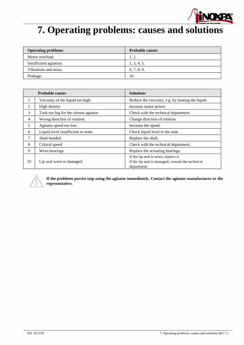
Operating problems Probable causes Motor overload. 1, 2. Insufficient agitation. 1, 3, 4, 5. Vibrations and noise. 6, 7, 8, 9. Peakage. 10.
Probable causes Solutions
1 Viscosity of the liquid too high. Reduce the viscosity, e.g. by heating the liquid. 2 High density. Increase motor power. 3 Tank too big for the chosen agitator. Check with the technical department. 4 Wrong direction of rotation. Change direction of rotation. 5 Agitator speed too low. Increase the speed. 6 Liquid level insufficient or none. Check liquid level in the tank. 7 Shaft bended. Replace the shaft. 8 Critical speed. Check with the technical department. 9 Worn bearings. Replace the actuating bearings.
10 Lip seal worn or damaged. If the lip seal is worn, replace it. If the lip seal is damaged, consult the technical department.
If the problems persist stop using the agitator immediately. Contact the agitator manufacturer or the representative.
ED. 2012/02 8. Disassembly and assembly BFI 8.1
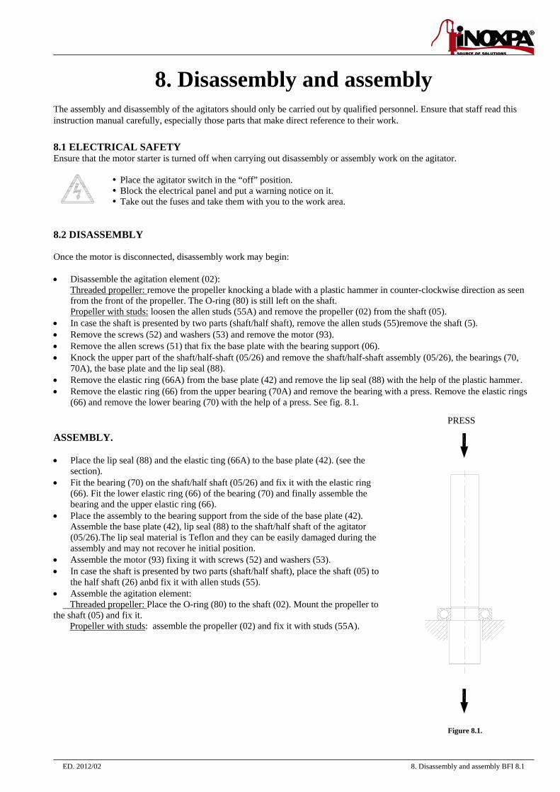
8. Disassembly and assembly The assembly and disassembly of the agitators should only be carried out by qualified personnel. Ensure that staff read this instruction manual carefully, especially those parts that make direct reference to their work. 8.1 ELECTRICAL SAFETY Ensure that the motor starter is turned off when carrying out disassembly or assembly work on the agitator.
Place the agitator switch in the “off” position. Block the electrical panel and put a warning notice on it. Take out the fuses and take them with you to the work area.
8.2 DISASSEMBLY Once the motor is disconnected, disassembly work may begin: • Disassemble the agitation element (02):
Threaded propeller: remove the propeller knocking a blade with a plastic hammer in counter-clockwise direction as seen from the front of the propeller. The O-ring (80) is still left on the shaft. Propeller with studs: loosen the allen studs (55A) and remove the propeller (02) from the shaft (05).
• In case the shaft is presented by two parts (shaft/half shaft), remove the allen studs (55)remove the shaft (5). • Remove the screws (52) and washers (53) and remove the motor (93). • Remove the allen screws (51) that fix the base plate with the bearing support (06). • Knock the upper part of the shaft/half-shaft (05/26) and remove the shaft/half-shaft assembly (05/26), the bearings (70,
70A), the base plate and the lip seal (88). • Remove the elastic ring (66A) from the base plate (42) and remove the lip seal (88) with the help of the plastic hammer. • Remove the elastic ring (66) from the upper bearing (70A) and remove the bearing with a press. Remove the elastic rings
(66) and remove the lower bearing (70) with the help of a press. See fig. 8.1. ASSEMBLY. • Place the lip seal (88) and the elastic ting (66A) to the base plate (42). (see the
section). • Fit the bearing (70) on the shaft/half shaft (05/26) and fix it with the elastic ring
(66). Fit the lower elastic ring (66) of the bearing (70) and finally assemble the bearing and the upper elastic ring (66).
• Place the assembly to the bearing support from the side of the base plate (42). Assemble the base plate (42), lip seal (88) to the shaft/half shaft of the agitator (05/26).The lip seal material is Teflon and they can be easily damaged during the assembly and may not recover he initial position.
• Assemble the motor (93) fixing it with screws (52) and washers (53). • In case the shaft is presented by two parts (shaft/half shaft), place the shaft (05) to
the half shaft (26) anbd fix it with allen studs (55). • Assemble the agitation element: Threaded propeller: Place the O-ring (80) to the shaft (02). Mount the propeller to the shaft (05) and fix it. Propeller with studs: assemble the propeller (02) and fix it with studs (55A).
Figure 8.1.
PRESS
ED. 2012/02 9. Technical specifications BFI 9.1
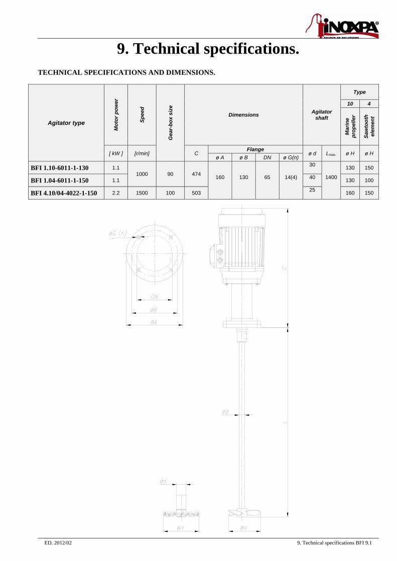
9. Technical specifications. TECHNICAL SPECIFICATIONS AND DIMENSIONS.
Agitator type M
otor
pow
er
Spee
d
Gea
r-bo
x si
ze
Dimensions Agitator shaft
Type
10 4
Mar
ine
prop
elle
r
Saw
toot
h el
emen
t
[ kW ] [r/min] C Flange
ø d Lmáx. ø H ø H ø A ø B DN ø G(n)
BFI 1.10-6011-1-130 1.1 1000 90 474 160
130
65
14(4)
30
1400
130 150
BFI 1.04-6011-1-150 1.1 40 130 100
BFI 4.10/04-4022-1-150 2.2 1500 100 503 25 160 150
9. Technical specifications BFI 9.2 ED. 2012/02
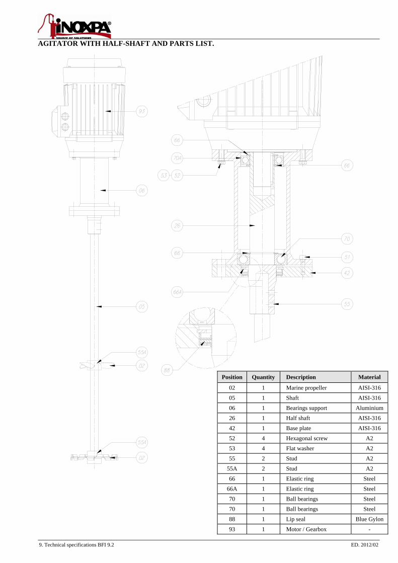
AGITATOR WITH HALF-SHAFT AND PARTS LIST.
Position Quantity Description Material
02 1 Marine propeller AISI-316
05 1 Shaft AISI-316
06 1 Bearings support Aluminium
26 1 Half shaft AISI-316
42 1 Base plate AISI-316
52 4 Hexagonal screw A2
53 4 Flat washer A2
55 2 Stud A2
55A 2 Stud A2
66 1 Elastic ring Steel
66A 1 Elastic ring Steel
70 1 Ball bearings Steel
70 1 Ball bearings Steel
88 1 Lip seal Blue Gylon
93 1 Motor / Gearbox -
ED. 2012/02 9. Technical specifications BFI 9.3
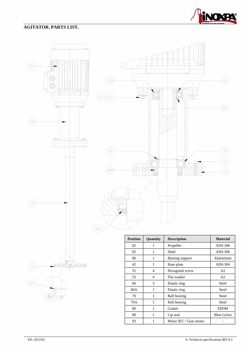
AGITATOR. PARTS LIST.
Position Quantity Description Material
02 1 Propeller AISI-306
05 1 Shaft AISI-306
06 1 Bearing support Aluminium
42 1 Base plate AISI-304
52 4 Hexagonal screw A2
53 4 Flat washer A2
66 3 Elastic ring Steel
66A 1 Elastic ring Steel
70 1 Ball bearing Steel
70A 1 Ball bearing Steel
80 1 Gasket EPDM
88 1 Lip seal Blue Gylon
93 1 Motor IEC / Gear motor -