bg bevel-gear units with
TRANSCRIPT
Dimensions in mm GE – 11/2015
< 6 arcmin
BG Bevel-Gear Units with <6' Backlash
PageBG Bevel-Gear Units with <6' Backlash
Size 50 GE2 – GE3Size 63 GE4 – GE5Size 80 GE6 – GE7
Couplings and Shrink-Disks GE8 – GE9
Selection and Load Tables GE10
Short Description GE11
Mounting and Maintenance GE12 – GE13
Motor Applications GI5 – GI9

Dimensions in mmGE – 2 1/2019
< 6 arcmin
51 23 005 51 33 005 4.75 6.3 0.57651 23 007 51 33 007 6.75 6.3 0.33051 23 009 51 33 009 9.25 6.3 0.194
Size BG 50
Size BG 50
Fig. 2 Output shaft for clamp connection 80 83 030
Fig. 1 Output shaft with key connection
BG Bevel-Gear Units with <6' Backlash
Jred 10-4Order CodeFig. 1 Fig. 2 Ratio i kg m2
With food grade oil, order code 51 23 1xx / 51 33 1xx. With ATEX version with food grade oil, order code 51 23 2xx / 51 33 2xx.
Dimensions in mm GE – 31/2015
< 6 arcmin
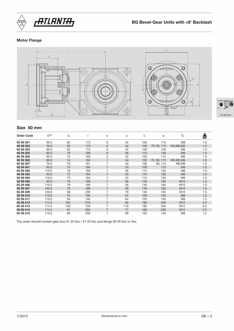
Motor Flange
Size 50 mm
Order Code DG7 k1 r x y f1 e G
65 59 301 95.0 62 173 6 42 100 115 M8 1.065 59 302 50.0 62 173 6 42 100 1.065 59 303 80.0 62 173 6 42 100 100 M6 1.065 59 304 95.0 78 189 6 58 115 130 M8 1.065 59 305 95.0 72 183 5 52 105 115 M8 1.065 59 306 60.0 74 184 7 54 100 1.065 59 307 70.0 70 181 7 50 100 1.065 59 401 95.0 73 184 7 53 100 115 M8 1.065 59 402 110.0 78 189 7 58 115 130 M8 1.065 59 403 95.0 73 184 7 53 115 130 M8 1.065 59 404 110.0 73 184 7 53 115 130 M8 1.065 59 405 95.0 78 189 7 58 140 165 M10 1.065 59 406 110.0 78 189 7 58 140 165 M10 1.065 59 407 130.0 78 189 7 58 140 165 M10 1.065 59 409 130.0 98 209 7 78 140 165 M10 1.565 59 410 110.0 74 185 7 54 120 145 M8 1.065 59 411 110.0 84 195 7 64 120 145 M8 1.565 59 412 114.3 105 216 7 85 180 200 M12 3.565 59 413 114.3 139 150 7 119 180 200 M12 6.065 59 414 114.3 91 202 7 71 180 200 M12 2.565 59 415 110.0 89 200 7 69 120 145 M8 1.5
The order should contain gear box 51 23 0xx / 51 33 0xx and flange 65 59 3xx or 4xx.
BG Bevel-Gear Units with <6' Backlash
M4,M6,M870, 95, 115
75, 90, 115 M5,M5,M8 90, 115 M6,M8
Dimensions in mmGE – 4 1/2019
< 6 arcmin
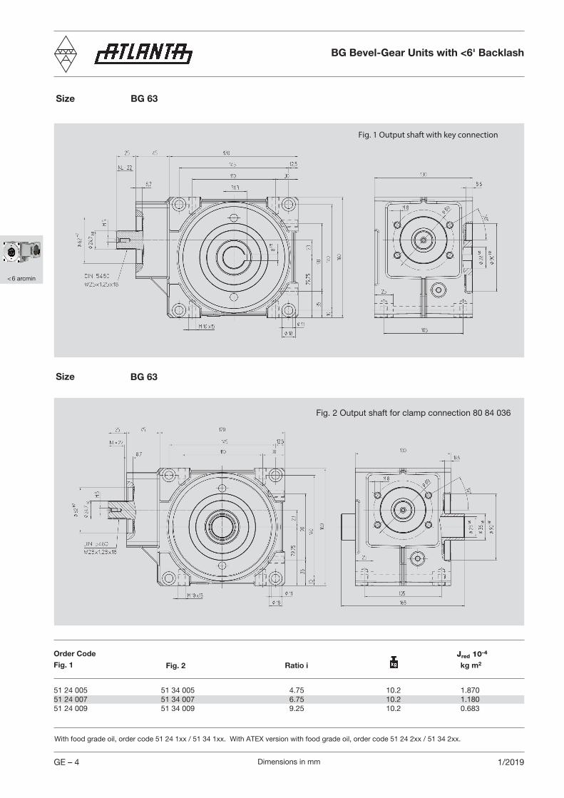
51 24 005 51 34 005 4.75 10.2 1.870 51 24 007 51 34 007 6.75 10.2 1.18051 24 009 51 34 009 9.25 10.2 0.683
Size BG 63
Size BG 63
BG Bevel-Gear Units with <6' Backlash
Jred 10-4Order CodeFig. 1 Fig. 2 Ratio i kg m2
Fig. 1 Output shaft with key connection
Fig. 2 Output shaft for clamp connection 80 84 036
With food grade oil, order code 51 24 1xx / 51 34 1xx. With ATEX version with food grade oil, order code 51 24 2xx / 51 34 2xx.
Dimensions in mm GE – 51/2015
< 6 arcmin
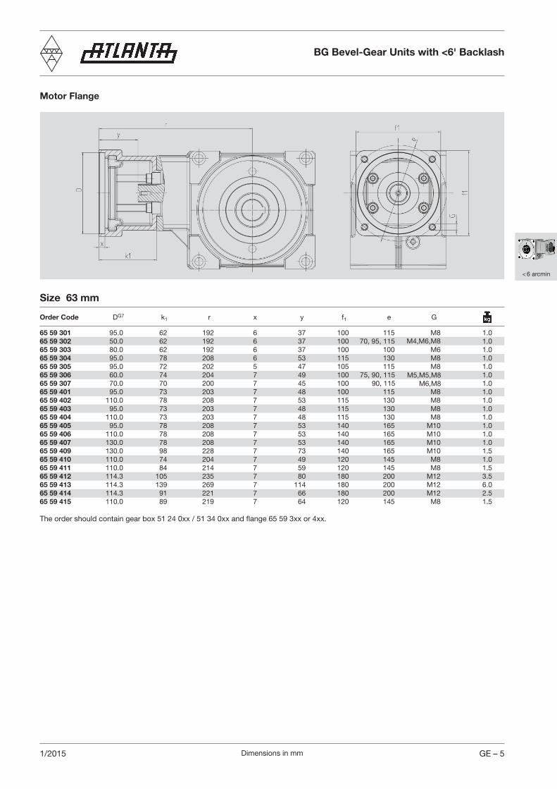
Motor Flange
The order should contain gear box 51 24 0xx / 51 34 0xx and flange 65 59 3xx or 4xx.
Size 63 mm
Order Code DG7 k1 r x y f1 e G
65 59 301 95.0 62 192 6 37 100 115 M8 1.065 59 302 50.0 62 192 6 37 100 M4,M6,M8 1.065 59 303 80.0 62 192 6 37 100 100 M6 1.065 59 304 95.0 78 208 6 53 115 130 M8 1.065 59 305 95.0 72 202 5 47 105 115 M8 1.065 59 306 60.0 74 204 7 49 100 75, 90, 115 M5,M5,M8 1.065 59 307 70.0 70 200 7 45 100 M6,M8 1.065 59 401 95.0 73 203 7 48 100 115 M8 1.065 59 402 110.0 78 208 7 53 115 130 M8 1.065 59 403 95.0 73 203 7 48 115 130 M8 1.065 59 404 110.0 73 203 7 48 115 130 M8 1.065 59 405 95.0 78 208 7 53 140 165 M10 1.065 59 406 110.0 78 208 7 53 140 165 M10 1.065 59 407 130.0 78 208 7 53 140 165 M10 1.065 59 409 130.0 98 228 7 73 140 165 M10 1.565 59 410 110.0 74 204 7 49 120 145 M8 1.065 59 411 110.0 84 214 7 59 120 145 M8 1.565 59 412 114.3 105 235 7 80 180 200 M12 3.565 59 413 114.3 139 269 7 114 180 200 M12 6.065 59 414 114.3 91 221 7 66 180 200 M12 2.565 59 415 110.0 89 219 7 64 120 145 M8 1.5
BG Bevel-Gear Units with <6' Backlash
70, 95, 115
90, 115

Dimensions in mmGE – 6 1/2019
< 6 arcmin
51 25 005 51 35 005 4.75 23.0 7.800 51 25 007 51 35 007 6.75 23.0 4.620 51 25 009 51 35 009 9.25 23.0 3.270
Size BG 80
Size BG 80
Fig. 1 Output shaft with key connection
Fig. 2 Output shaft for clamp connection 80 85 050
BG Bevel-Gear Units with <6' Backlash
Jred 10-4Order CodeFig. 1 Fig. 2 Ratio i kg m2
With food grade oil, order code 51 25 1xx / 51 35 1xx. With ATEX version with food grade oil, order code 51 25 2xx / 51 35 2xx.
Dimensions in mm GE – 71/2015
< 6 arcmin
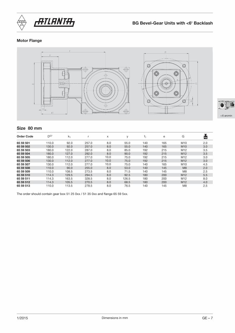
Motor Flange
The order should contain gear box 51 25 0xx / 51 35 0xx and flange 65 59 5xx.
Size 80 mm
Order Code DG7 k1 r x y f1 e G
65 59 501 110.0 92.0 257.0 8.0 55.0 140 165 M10 2.065 59 502 130.0 92.0 257.0 8.0 55.0 140 165 M10 3.065 59 503 180.0 122.0 287.0 8.0 85.0 192 215 M12 3.565 59 504 180.0 127.0 292.0 8.0 90.0 192 215 M12 3.565 59 505 180.0 112.0 277.0 10.0 75.0 192 215 M12 3.065 59 506 130.0 112.0 277.0 10.0 75.0 192 215 M12 3.065 59 507 130.0 112.0 277.0 10.0 75.0 140 165 M10 4.565 59 508 110.0 90.0 255.0 8.0 53.0 140 145 M8 2.065 59 509 110.0 108.5 273.5 8.0 71.5 140 145 M8 2.565 59 510 114.3 129.5 294.5 8.0 92.5 180 200 M12 5.565 59 511 114.3 163.5 328.5 8.0 126.5 180 200 M12 8.065 59 512 114.3 105.5 270.5 8.0 68.5 180 200 M12 4.065 59 513 110.0 113.5 278.5 8.0 76.5 140 145 M8 2.5
BG Bevel-Gear Units with <6' Backlash
Dimensions in mmGE – 8 1/2015
Connecting Elements
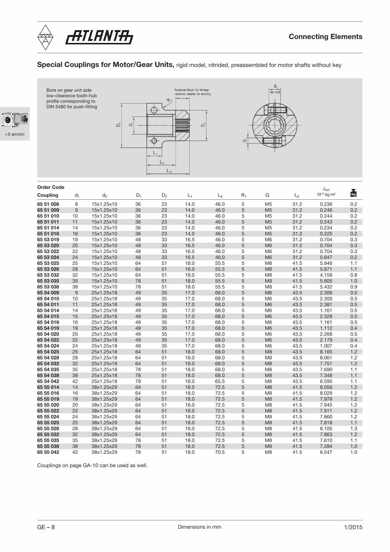
Special Couplings for Motor/Gear Units, rigid model, nitrided, preassembled for motor shafts without key
Bore on gear unit side low-clearance tooth-hubprofile corresponding toDIN 5480 for push-fitting
Order Code
Coupling d1 d2 D1 D2 L1 L3 R1 G L2
Couplings on page GA-10 can be used as well.
65 51 008 8 15x1.25x10 36 23 14.0 46.0 5 M5 31.2 0.236 0.265 51 009 9 15x1.25x10 36 23 14.0 46.0 5 M5 31.2 0.246 0.265 51 010 10 15x1.25x10 36 23 14.0 46.0 5 M5 31.2 0.244 0.265 51 011 11 15x1.25x10 36 23 14.0 46.0 5 M5 31.2 0.243 0.265 51 014 14 15x1.25x10 36 23 14.0 46.0 5 M5 31.2 0.234 0.265 51 016 16 15x1.25x10 36 23 14.0 46.0 5 M5 31.2 0.225 0.265 53 019 19 15x1.25x10 48 33 16.5 46.0 5 M6 31.2 0.704 0.365 53 020 20 15x1.25x10 48 33 16.5 46.0 5 M6 31.2 0.704 0.365 53 022 22 15x1.25x10 48 33 16.5 46.0 5 M6 31.2 0.704 0.365 53 024 24 15x1.25x10 48 33 16.5 46.0 5 M6 31.2 0.647 0.265 53 025 25 15x1.25x10 64 51 18.0 55.5 5 M8 41.5 5.946 1.165 53 028 28 15x1.25x10 64 51 18.0 55.5 5 M8 41.5 5.871 1.165 53 032 32 15x1.25x10 64 51 18.0 55.5 5 M8 41.5 4.158 0.865 53 035 35 15x1.25x10 78 51 18.0 55.5 5 M8 41.5 5.605 1.065 53 038 38 15x1.25x10 78 51 18.0 55.5 5 M8 41.5 5.432 0.965 54 009 9 25x1.25x18 49 35 17.0 68.0 5 M6 43.5 2.306 0.565 54 010 10 25x1.25x18 49 35 17.0 68.0 5 M6 43.5 2.300 0.565 54 011 11 25x1.25x18 49 35 17.0 68.0 5 M6 43.5 2.381 0.565 54 014 14 25x1.25x18 49 35 17.0 68.0 5 M6 43.5 1.161 0.565 54 015 15 25x1.25x18 49 35 17.0 68.0 5 M6 43.5 2.328 0.565 54 016 16 25x1.25x18 49 35 17.0 68.0 5 M6 43.5 1.161 0.565 54 019 19 25x1.25x18 49 35 17.0 68.0 5 M6 43.5 1.112 0.465 54 020 20 25x1.25x18 49 35 17.0 68.0 5 M6 43.5 2.268 0.565 54 022 22 25x1.25x18 49 35 17.0 68.0 5 M6 43.5 2.179 0.465 54 024 24 25x1.25x18 49 35 17.0 68.0 5 M6 43.5 1.007 0.465 54 025 25 25x1.25x18 64 51 18.0 68.0 5 M8 43.5 8.165 1.265 54 028 28 25x1.25x18 64 51 18.0 68.0 5 M8 43.5 8.061 1.265 54 032 32 25x1.25x18 64 51 18.0 68.0 5 M8 43.5 7.751 1.265 54 035 35 25x1.25x18 78 51 18.0 68.0 5 M8 43.5 7.690 1.165 54 038 38 25x1.25x18 78 51 18.0 68.0 5 M8 43.5 7.348 1.165 54 042 42 25x1.25x18 78 51 18.0 65.5 5 M8 43.5 6.595 1.165 55 014 14 38x1.25x29 64 51 18.0 72.5 5 M8 41.5 8.056 1.265 55 016 16 38x1.25x29 64 51 18.0 72.5 5 M8 41.5 8.029 1.265 55 019 19 38x1.25x29 64 51 18.0 72.5 5 M8 41.5 7.978 1.265 55 020 20 38x1.25x29 64 51 18.0 72.5 5 M8 41.5 7.945 1.265 55 022 22 38x1.25x29 64 51 18.0 72.5 5 M8 41.5 7.911 1.265 55 024 24 38x1.25x29 64 51 18.0 72.5 5 M8 41.5 7.860 1.265 55 025 25 38x1.25x29 64 51 18.0 72.5 5 M8 41.5 7.818 1.165 55 028 28 38x1.25x29 64 51 18.0 72.5 5 M8 41.5 8.105 1.365 55 032 32 38x1.25x29 64 51 18.0 72.5 5 M8 41.5 7.863 1.265 55 035 35 38x1.25x29 78 51 18.0 72.5 5 M8 41.5 7.610 1.165 55 038 38 38x1.25x29 78 51 18.0 72.5 5 M8 41.5 7.284 1.065 55 042 42 38x1.25x29 78 51 18.0 70.5 5 M8 41.5 6.547 1.0
Jred 10-4 kg m²
< 6 arcmin
Dimensions in mm GE – 91/2015
< 6 arcmin
J 10-4 kg m²
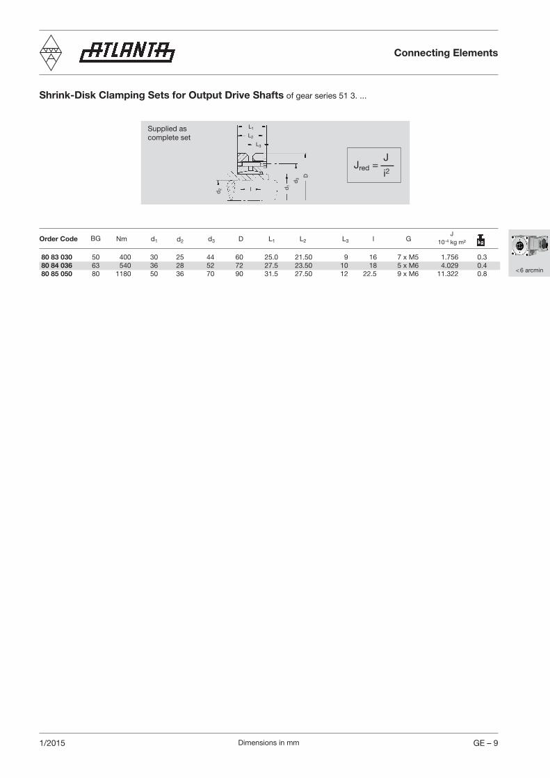
Jred =J
i2
Supplied ascomplete set
d2 d
1
d3 D
L1
L2
L3
l
Shrink-Disk Clamping Sets for Output Drive Shafts of gear series 51 3. ...
Order Code Nm d1 d2 d3 D L1 L2 L3 l G
Connecting Elements
80 83 030 50 400 30 25 44 60 25.0 21.50 9 16 7 x M5 1.756 0.380 84 036 63 540 36 28 52 72 27.5 23.50 10 18 5 x M6 4.029 0.480 85 050 80 1180 50 36 70 90 31.5 27.50 12 22.5 9 x M6 11.322 0.8
BG

Dimensions in mmGE – 10 1/2019
Additional loads on output driveThe data given are reference values. You should consider the values arising from the choice of the tooth system. It is assumed that the point of action of the force is the center of the shaft. In cases where additional axial forces occur, over and above high transverse forces, please ask for advice.
l
FnZ
FaZ
a
Selection and Load Table for BG Bevel-Gear Units
Input Speed n1 (rpm)Order Code BG i T2 max. 500 750 1000 1500 3000 4000 5000 η
P1 T2 P1 T2 P1 T2 P1 T2 P1 T2 P1 T2 P1 T2 at(kw) (Nm) (kw) (Nm) (kw) (Nm) (kw) (Nm) (kw) (Nm) (kw) (Nm) (kw) (Nm) 1500
51 23 _05 51 33 _05 50 4.75 145 1.14 97 1.71 97 2.28 97 3.41 97 6.82 97 9.10 97 11.37 97 0.9451 23 _07 51 33 _07 6.75 125 0.57 68 0.86 68 1.15 68 1.72 68 3.44 68 4.59 68 5.73 68 0.9251 23 _09 51 33 _09 9.25 100 0.35 56 0.53 56 0.70 56 1.06 56 2.11 56 2.82 56 3.52 56 0.90
51 24 _05 51 34 _05 63 4.75 305 2.34 200 3.52 200 4.69 200 7.04 200 14.07 200 18.76 200 23.45 200 0.9451 24 _07 51 34 _07 6.75 280 1.22 145 1.83 145 2.45 145 3.67 145 7.33 145 9.78 145 12.22 145 0.9251 24 _09 51 34 _09 9.25 245 0.81 128 1.21 128 1.61 128 2.42 128 4.83 128 6.44 128 8.05 128 0.90
51 25 _05 51 35 _05 80 4.75 750 5.86 500 8.79 500 11.73 500 17.59 500 35.18 500 46.90 500 58.63 500 0.9451 25 _07 51 35 _07 6.75 660 2.99 355 4.49 355 5.99 355 8.98 355 17.96 355 23.94 355 29.93 355 0.9251 25 _09 51 35 _09 9.25 510 1.73 275 2.59 275 3.46 275 5.19 275 10.38 275 13.84 275 17.29 275 0.90
BG Bevel-Gear Units
Size BG 50 63 80
Dimension center of casing to centerof pinion l (mm) 90 140 110 160 125 175
Max. additional loadradial Frz [N] 4000 2570 6000 4120 7500 5360axial Faz [N] 1800 1800 2800 2800 3500 3500
The values in the tables are based upon wear or maximum flank load at 12,000 hours full load and on servo-operation. With continuous full-load operation it may be necessary to consider temperature limits! (Please ask us, if in doubt.)
T2max. = static torque to avoid tooth fracture, P1 = driving power in kW, T2 = output torque in Nm.
< 6 arcmin
Dimensions in mm GE – 111/2015
< 6 arcmin
BG Bevel-Gear Units
Short Description
ATLANTA BG servo bevel-gear units have been specially developed for use with new generation three-phase AC motors and DC motors. Like all other items in this catalog they are usually available from stock or within very short time.
Our servo bevel-gear units feature:
– gear ratios which are similar, sometimes identical with those of the series 98, 58, and 59– low-clearance gearing (backlash < 6’)– light-alloy housing for optimal heat dissipation– robust tapered-roller bearing of the output hollow shaft for high additional forces– low moments of inertia for high dynamics
Sizes and gear ratios correspond with those of the existing servo worm-gear unit series. The bevel-gears are manufactured and installed with optimal tooth bearing. The use of bevel-gears end-lapped in sets guarantees smooth running in both directions of rotation. The housing is machined on all sides and provided with many fixing holes and threaded bores and can thus be installed in any mounting position desired.
The drive or the connection to the driving motor, is realized via a special clutch. The internal gearing of this clutch in combination with the barrelled profile of the driving shaft of our bevel-gear units assures the flow of forces without play.
For the output drive we offer quite a number of output shafts with straight or helical tooth systems and with different numbers of teeth. Besides pinion shafts it is possible to combine and use a large variety of other numbers of teeth from our gear-wheel program with matching special output shafts. It goes without saying that analogous to our gear units the complete range of output shafts is not only available for key fitting but also for shrink-disk fitting.
Our wide range of standard elements for servo drives is supplemented by racks. The ex-stock program comprises many different types from rather simple, soft racks through hardened versions with straight tooth system or optionally with helical tooth system for smooth running, to racks ground on all sides to very narrow tolerances.
For emergency stops, the maximum transmittable torque of the gear unit (see page GE-10) and shrink disk (see page GH-1) has to be checked. The output keyway has to be calculated separately.
Dimensions in mmGE – 12 1/2015
< 6 arcmin
Mounting and Maintenance BG Bevel-Gear Units
Mounting Instructions
Bevel-Gear Unit Five machined mounting surfaces with sufficiently dimensioned fixing holes and threaded bores are provided for tension-free installation in any mounting position. In order to make full use of the additional dynamic forces (see p. GE-10) we recommend to choose the largest available contact surfaces, i.e. on the side of the cover or on the opposite side. Lubrication conditions are almost the same in all mounting positions.
CouplingThe coupling is supplied pre-assembled. Before fixing it on the motor shaft carefully clean all contact surfaces and protect them with a thin oil film. An important dimension for mounting is ”X1” (compare pages GI – 5 to GI – 9)
We recommend to proceed as follows: – Clean the contact surfaces and protect them with a thin oil film.– Position the coupling on the motor shaft at the distance ”X1” (see pages GI – 5 to GI – 9) using a depth gauge for
determining this dimension.– Slightly tighten the screws alternately and check the coupling for true running– Observe the tightening torque indicated in the operation and maintenance instructions bearing in mind that the width of
the gap on both sides of the clutch must remain the same.– It is advisable to make another final concentricity check at the reference collar.
A mounting guide can be found on page GI-5 to GI-9
MotorInsert the motor with coupling mounted into the gear centering piece and bolt it to the gearbox.
Output Pinion ShaftUnless the output pinion shaft comes already fully assembled, we recommend to proceed as follows:Clean pinion shaft and hollow shaft extension and then oil them. For the special output drive shaft we recommend tolerance h6 (DIN ISO286). the material must have a minimum yield point of 385 N/mm². A recalculation of the strength is necessary.
Output Drive Shaft for Shrink-Disk Connec tionSlide shrink disk onto the hollow shaft extension of the gear unit (please do not tighten the screws beforehand!).Insert the output shaft from the desired side into the hollow shaft fully up to the stop. Make the transverse pressure connection by evenly tightening the clamping screws. Tighten the screws one after the other (not crosswise) in several passes to the torque indicated in the operation and maintenance instructions.

Dimensions in mm GE – 131/2015
< 6 arcmin
Output Drive Shaft for Key ConnectionThe retaining ring, the disc and the screw supplied with the output drive shaft serve for locking the output shaft in axial direction. For this purpose insert the retaining ring in the applicable recess of the hollow shaft and slide the output drive shaft from the desired side into the hollow shaft up to the stop. Disc and screw are screwed to the output shaft from the other side of the gear unit. The retaining ring must be clamped between disc and pinion shaft.
Maintenance
Lubricant ChangeATLANTA servo bevel-gear units are filled with synthetic polyclycol oil.Under the following conditions this means lifetime lubricacaton:The layout of the gear unit is made strictly in conformance with the guidelines specified in the ATLANTA catalogue and the gear unit is operated exclusively within the permissible characteristic values and limits. The operator checks the gear regularly (every 4 weeks) for oil leakage. The surface temperature does not exceed max. 80° C. Experience has shown that this temperature is not reached with servo-operation (intermittent operation).
We recommend the following synthetic gear lubricant:Klübersynth GH 6 - 220Order Code: 65 90 010 (1 liter)
Alternative:SHELL Tivela S 220, BP Enersyn SG-XP 220, ARAL Degol GS 220
Degree to ProtectionDegree of protection: IP65/67 according to ISO 20653 (Corrosion has to be verified separately).
Size Oil Quantity
BG 50 0.3 lBG 63 0.5 lBG 80 1.2 l
Mounting and Maintenance BG Bevel-Gear Units