bg0088 rev 05.2 manual magnetic tofd scanner
TRANSCRIPT

STIX
Manual Magnetic TOFD ScannerBG0088 Rev 05.2

PAGE i of iv BG0088 Rev 05.2
SAFETY WARNINGS / PRECAUTIONS
DANGER! The STIX is designed for a specific use. Using the STIX outside of its intended use could cause damage to the product. Read and understand this manual before using.
KEEP THIS MANUAL – DO NOT LOSETHIS MANUAL IS PART OF THE STIX AND MUST BE RETAINED FOR THE LIFE OF
THE PRODUCT. PASS ON TO SUBSEQUENT OWNERS.Ensure any amendments are incorporated with this document.
WARNING! Do NOT operate scanner in an explosive environment. Do NOT operate scanner in the presence of volatile substances.
The WEEE symbol indicates that the product must not be disposed of as unsorted municipal waste, but should be collected separately.
(see “MANUFACTURER:” on page 1)
WARNING! Can be harmful to pacemaker and ICD wearers. Stay at least 25 cm (10 in) away.

PAGE ii of iv
Chapter
1 Identification 1
1.1. Product Brand 11.2. Manufacturer 1
Chapter
2 Product Specifications 2
2.1. Intended Use 22.1.1. Operating Limits 22.1.2. Operating Environment 2
2.2. Dimensions and Weight 22.3. Environmental Sealing 32.4. Performance Specifications 3
Chapter
3 Definitions 4
3.1. Definitions of Symbols 4
Chapter
4 System Components 5
4.1. Component Identification 54.2. Tools 64.3. Handle 6
4.3.1. Sleeving 74.4. Wheel Block 8
4.4.1. Wheel Installation 94.4.2. Wheel Removal 94.4.3. Ratchet Lever 9
4.5. Frame Bar 104.6. Spring-Loaded Encoder 104.7. Pivot Buttons 104.8. Spring-Loaded Probe Holder 11
4.8.1. Probe Holder Setup 114.9. Magnetic Wheel Kit 134.10. Pre-Amp Bracket 14
Chapter
5 Preparation For Use 15
5.1. Configurations 155.1.1. Two Probe TOFD 155.1.2. Two Probe TOFD Cantilever 15
TABLE OF CONTENTS

PAGE iii of iv BG0088 Rev 05.2
Chapter
6 Operation 16
6.1. STIX setup on a scan surface 16
Chapter
7 Maintenance 19
Chapter
8 Troubleshooting 20
8.1. Technical Support 20
Chapter
9 Spare Parts 21
9.1. Scanner 219.2. Kit Components 22
9.2.1. Encoder Connector Type 239.3. Accessories 23
9.3.1. Magnetic Wheel Kit 239.3.2. Pre-Amp Bracket 239.3.3. Cable Management 24
9.3.3.1 Cable Management Length 249.4. Probe Holders 25
9.4.1. Slip Joint Probe Holder Parts 259.4.2. Vertical Probe Holder Parts 26
9.5. Probe Holder Components 279.5.1. Spring-Loaded Arm Style 279.5.2. Slip Joint and Vertical Probe Holder Arm Style 279.5.3. Slip Joint and Vertical Probe Holder Yoke Style 279.5.4. Swing Arm Style 279.5.5. Pivot Button Style 28
9.6. Variable Components 289.6.1. Frame Bars 28
Chapter
10 Disposal 29
Chapter
11 Limited Warranty 30

PAGE iv of iv

PAGE 1 of 31 BG0088 Rev 05.2
Chapter 1
IDENTIFICATION
1.1. Product Brand The STIX is a manual operated scanner with spring-loaded encoder and magnetic wheels. It is designed to translate TOFD probes around ferrous piping.
1.2. Manufacturer DISTRIBUTOR:
Jireh Industries Ltd.
53158 Range Road 224Ardrossan, Alberta, CanadaT8E 2K4
Phone: 780.922.4534
jireh.com
MANUFACTURER:
PAGE 2 of 31
Chapter 2
PRODUCT SPECIFICATIONS
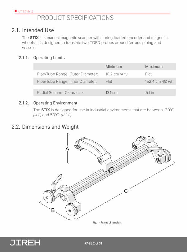
2.1. Intended Use The STIX is a manual magnetic scanner with spring-loaded encoder and magnetic wheels. It is designed to translate two TOFD probes around ferrous piping and vessels.
2.1.1. Operating Limits
Minimum Maximum
Pipe/Tube Range, Outer Diameter: 10.2 cm (4 in) Flat
Pipe/Tube Range, Inner Diameter: Flat 152.4 cm (60 in)
Radial Scanner Clearance: 13.1 cm 5.1 in
2.1.2. Operating Environment The STIX is designed for use in industrial environments that are between -20°C (-4°F) and 50°C (122°F).
2.2. Dimensions and Weight
A
B
C
Fig. 1 - Frame dimensions

PAGE 3 of 31 BG0088 Rev 05.2
A: 10.5 cm 4.1 in
B: 17.5 cm 6.9 in
C: 45.4 cm 17.9 in
Frame Weight: 1.19 kg 2.6 lb
Encoder Cable Length (Standard Kit): 5 m 16.4 ft
2.3. Environmental SealingWatertight (submersible), (contact Jireh Industries Ltd. on page 1 for details).
2.4. Performance Specifications
X-Axis Encoder Resolution: 9.05 counts/mm 230.0 counts/inch

PAGE 4 of 31
Chapter 3
DEFINITIONS
3.1. Definitions of Symbols
Instructions to ‘look here’ or to ‘see this part’
Denotes movement. Instructing user to carry out action in a specified direction.
Indicates alignment axis, can also indicate insertion or movement of parts.
Alerts user that view has changed to a reverse angle.

PAGE 5 of 31 BG0088 Rev 05.2
Chapter 4
SYSTEM COMPONENTS
4.1. Component Identification
Fig. 2 - STIX Frame BGA008-
Fig. 3 - Spring-Loaded Probe Holder PHS033-
Fig. 4 - Frame Bar BG0038-
Fig. 5 - Magnetic Wheel BTS031
Fig. 6 - STIX Case BTA010
Fig. 7 - Irrigation Kit CMG007
Fig. 8 - BGS053- Spring-Loaded Encoder
Fig. 9 - 3/8 in Wrench EA470
Fig. 10 - 3 mm Hex Wrench EA414
PAGE 6 of 31
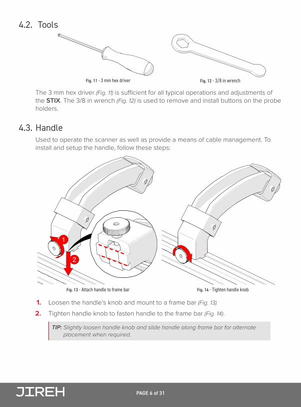
4.2. Tools
The 3 mm hex driver (Fig. 11) is sufficient for all typical operations and adjustments of the STIX. The 3/8 in wrench (Fig. 12) is used to remove and install buttons on the probe holders.
4.3. Handle Used to operate the scanner as well as provide a means of cable management. To install and setup the handle, follow these steps:
1. Loosen the handle’s knob and mount to a frame bar (Fig. 13).
2. Tighten handle knob to fasten handle to the frame bar (Fig. 14).
TIP: Slightly loosen handle knob and slide handle along frame bar for alternate placement when required.
Fig. 11 - 3 mm hex driver Fig. 12 - 3/8 in wrench
1
2
Fig. 13 - Attach handle to frame bar Fig. 14 - Tighten handle knob
PAGE 7 of 31 BG0088 Rev 05.2
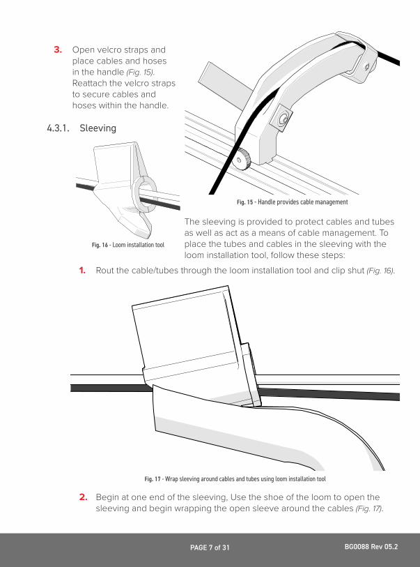
3. Open velcro straps and place cables and hoses in the handle (Fig. 15). Reattach the velcro straps to secure cables and hoses within the handle.
4.3.1. Sleeving
The sleeving is provided to protect cables and tubes as well as act as a means of cable management. To place the tubes and cables in the sleeving with the loom installation tool, follow these steps:
1. Rout the cable/tubes through the loom installation tool and clip shut (Fig. 16).
2. Begin at one end of the sleeving, Use the shoe of the loom to open the sleeving and begin wrapping the open sleeve around the cables (Fig. 17).
Fig. 15 - Handle provides cable management
Fig. 16 - Loom installation tool
Fig. 17 - Wrap sleeving around cables and tubes using loom installation tool
PAGE 8 of 31
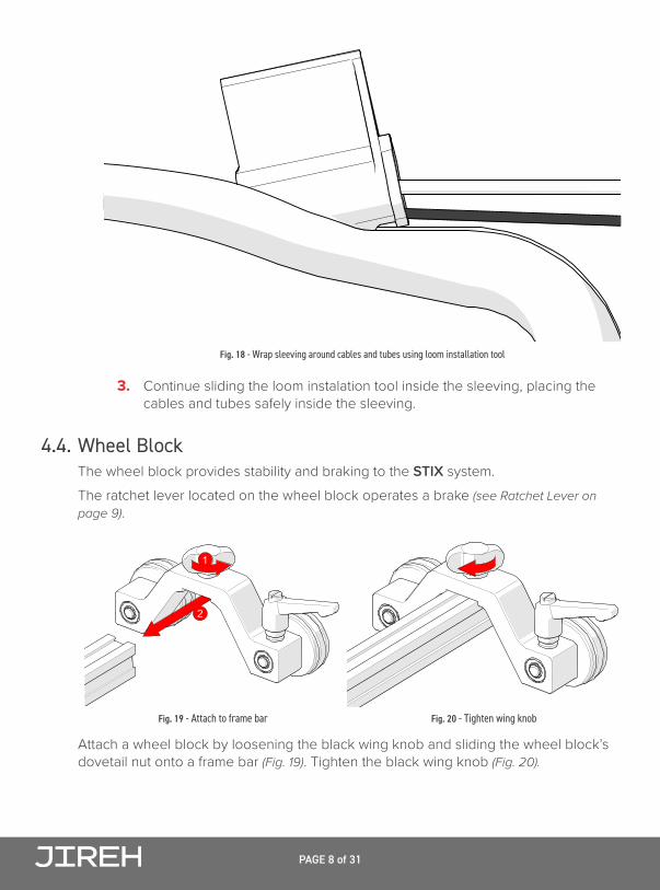
3. Continue sliding the loom instalation tool inside the sleeving, placing the cables and tubes safely inside the sleeving.
4.4. Wheel Block The wheel block provides stability and braking to the STIX system.The ratchet lever located on the wheel block operates a brake (see Ratchet Lever on page 9).
Attach a wheel block by loosening the black wing knob and sliding the wheel block’s dovetail nut onto a frame bar (Fig. 19). Tighten the black wing knob (Fig. 20).
Fig. 18 - Wrap sleeving around cables and tubes using loom installation tool
1
2
Fig. 19 - Attach to frame bar Fig. 20 - Tighten wing knob
PAGE 9 of 31 BG0088 Rev 05.2
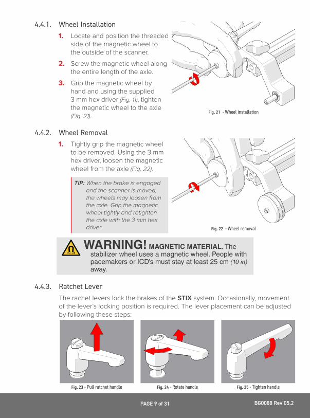
4.4.1. Wheel Installation 1. Locate and position the threaded
side of the magnetic wheel to the outside of the scanner.
2. Screw the magnetic wheel along the entire length of the axle.
3. Grip the magnetic wheel by hand and using the supplied 3 mm hex driver (Fig. 11), tighten the magnetic wheel to the axle (Fig. 21).
4.4.2. Wheel Removal 1. Tightly grip the magnetic wheel
to be removed. Using the 3 mm hex driver, loosen the magnetic wheel from the axle (Fig. 22).
TIP: When the brake is engaged and the scanner is moved, the wheels may loosen from the axle. Grip the magnetic wheel tightly and retighten the axle with the 3 mm hex driver.
4.4.3. Ratchet Lever The rachet levers lock the brakes of the STIX system. Occasionally, movement of the lever’s locking position is required. The lever placement can be adjusted by following these steps:
Fig. 21 - Wheel installation
Fig. 22 - Wheel removal
WARNING! MAGNETIC MATERIAL. The stabilizer wheel uses a magnetic wheel. People with pacemakers or ICD’s must stay at least 25 cm (10 in) away.
Fig. 23 - Pull ratchet handle Fig. 24 - Rotate handle Fig. 25 - Tighten handle

PAGE 10 of 31
1. Pull the ratchet lever away from the base of which it is connected (Fig. 23).
2. Continue to pull while rotating the lever in the appropriate direction (Fig. 24).3. Release the lever and utilize the new tightening position (Fig. 25).
4.5. Frame Bar Frame bars (Fig. 26) are used to mount probe holders, probe positioning systems and other accessories.Frame bars are available in a variety of lengths (see Frame Bar on page 10).
4.6. Spring-Loaded Encoder The spring-loaded encoder wheel provides vertical travel while maintaining contact pressure to the scan surface. To install the encoder follow these steps:
1. Loosen the encoder’s dovetail jaw and mount to the frame bar (Fig. 27).2. Tighten the encoder knob (Fig. 28).3. Spring tension maintains encoder contact with the scan surface (Fig. 29).
4.7. Pivot Buttons Available in a variety of shapes and sizes fitting various wedge dimensions.Use the supplied 3/8 in wrench (Fig. 12) to remove and install pivot buttons (Fig. 30).
Fig. 26 - Frame bar
1
2
Fig. 27 - Attach to frame bar Fig. 28 - Tighten knob Fig. 29 - Place on scan surface
2
1
Fig. 30 - Pivot buttons

PAGE 11 of 31 BG0088 Rev 05.2
4.8. Spring-Loaded Probe Holder
A Frame Bar
B Probe Holder Adjustment Knob
C Yoke
D Probe Holder Arm Adjustment Knob
E Probe Holder Arm
F Pivot Button
G Arm Clamp Screw
4.8.1. Probe Holder Setup To mount a TOFD wedge in the spring-loaded probe holder, follow these steps:
1. Rotate the probe holder adjustment knob and attach the probe holder to a frame bar (Fig. 32).
2. Use the probe holder adjustment knob to position the probe holder along the frame bar (Fig. 33).
2A
G
B
C
FE
D
Fig. 31 - Spring-loaded probe holder
Fig. 32 - Attach to frame bar
2
1
Fig. 33 - Position on frame bar
1
2

PAGE 12 of 31
TIP: Wedge pivoting may be impeded when utilizing pivot buttons closer to the yoke. (see Pivot Buttons on page 10)
3. Loosen the probe holder arm adjustment knob (Fig. 34) and remove outer probe holder arm from the yoke.
4. Adjust inner probe holder arm as required to best centre the probe on the yoke’s pivot axis (Fig. 34).
TIP: The probe holder yoke can ac-commodate different probe and wedge sizes of varying widths. It is best to centre the wedge with the yoke’s pivot axis to reduce wedge tipping when scanning. Position the inner probe holder arm accordingly with the centre of the yoke (Fig. 35).
5. Position the wedge on the inner probe holder arm (Fig. 35).
6. Slide outer probe holder arm along the yoke pinching the wedge in place (Fig. 35).
7. Tighten the probe holder arm adjustment knob (Fig. 36).
Fig. 34 - Adjust inner probe holder arm Fig. 35 - Place wedge and outer arm
Fig. 36 - Tighten probe holder knob

PAGE 13 of 31 BG0088 Rev 05.2
4.9. Magnetic Wheel Kit
WARNING! MAGNETIC MATERIAL. The magnetic wheel kit produce a magnetic field which may cause failure or permanent damage to items such as watches, memory devices, CRT monitors, medical devices or other electronics. People with pacemakers or ICD’s must stay at least 25 cm (10 in) away.
Two sets of the magnetic wheels can be used with the STIX, thus doubling the magnetic force.
NOTE: Magnetic wheels may lose their magnetic properties if heated above 175° F (80° C).
To install additional magnetic wheels, follow these steps:
1. Ensure the four existing wheels are tight (see Wheel Installation on page 9) 2. On the magnetic wheel to be attached, locate the threaded side of the magnetic
wheel, orient this threaded side towards the scanner.3. By hand, grip the wheel already attached to the wheel block. Overcome the
magnetic resistance to screw the additional wheel to the axle of the wheel block (Fig. 37).
4. Hold steady the magnetic wheel closest to the scanner body, insert the 3 mm hex driver into the axle and tighten the additional wheel (Fig. 38).
TIP: To remove additional wheels, reverse these steps.
Fig. 37 - Screw on additional magnetic wheel Fig. 38 - Tighten with 3 mm hex driver
PAGE 14 of 31
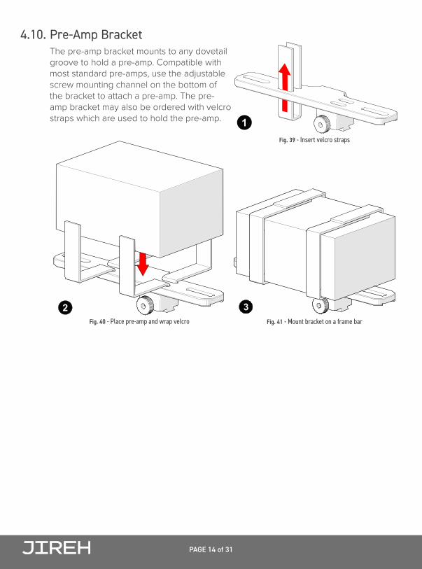
4.10. Pre-Amp Bracket The pre-amp bracket mounts to any dovetail groove to hold a pre-amp. Compatible with most standard pre-amps, use the adjustable screw mounting channel on the bottom of the bracket to attach a pre-amp. The pre-amp bracket may also be ordered with velcro straps which are used to hold the pre-amp.
Fig. 39 - Insert velcro straps
1
Fig. 40 - Place pre-amp and wrap velcro
2Fig. 41 - Mount bracket on a frame bar
3

PAGE 15 of 31 BG0088 Rev 05.2
Chapter 5
PREPARATION FOR USE
5.1. Configurations
5.1.1. Two Probe TOFD
5.1.2. Two Probe TOFD Cantilever Fig. 42 - Two probe TOFD configuration
Fig. 43 - Two probe TOFD cantilever configuration

PAGE 16 of 31
Chapter 6
OPERATION
6.1. STIX setup on a scan surface 1. Mount TOFD wedges to the probe
holders (see Spring-Loaded Probe Holder on page 11).
TIP: Mounting the wedges to the spring-loaded probe holders can be easier when the probe holders are separate from the STIX frame bar.
2. Assemble the appropriate configuration (Fig. 45). Attach the spring-loaded probe holders to the frame bar where appropriate.
3. Ensure the brakes are locked on the wheel blocks (see Ratchet Lever on page 9).
Fig. 44 - Mount wedges to probe holders
Fig. 45 - Attach spring-loaded probe holders to appropriate configuration
PAGE 17 of 31 BG0088 Rev 05.2
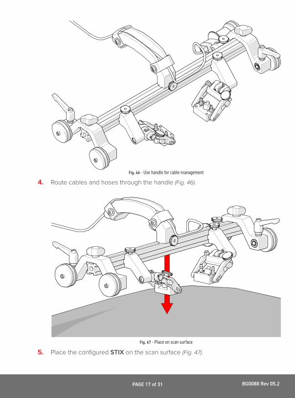
4. Route cables and hoses through the handle (Fig. 46).
5. Place the configured STIX on the scan surface (Fig. 47).
Fig. 46 - Use handle for cable management
Fig. 47 - Place on scan surface

PAGE 18 of 31
TIP: Use caution when placing equipment on the scan surface. The magnetized wheels can cause the assembly to lurch towards the metal suddenly.
6. The spring-loaded probe holders are designed to maintain wedge contact with the scan surface (Fig. 48), as well, the encoder is designed to maintain contact pressure on the scan surface for accurate reading.
7. Release the both brakes to begin scanning procedure.
Fig. 48 - Prepared for scanning

PAGE 19 of 31 BG0088 Rev 05.2
Chapter 7
MAINTENANCE
General cleaning of components is important to keep your system working well. All components that have no wiring or cables are completely waterproof. Components can be washed with warm water, dish soap and a medium bristle brush.Before using the scanner, ensure all connectors are free of water and moisture.
NOTE: All components with wiring, cables or electrical connections are splash proof. However, these components are NOT submersible.
NOTE: Never use strong solvents or abrasive materials to clean your scanner components.

PAGE 20 of 31
Chapter 8
TROUBLESHOOTING
Problem Possible Cause Solution
Encoder not functioning.
Instrument not properly setup.
Refer to instrument’s documentation regarding proper setup.
Issue with encoder. Contact Jireh Industries for repair (see Jireh Industries Ltd. on page 1).
Insufficient probe contact.
Scanner not set properly.
Reconfigure the scanner as per instructions (see Spring-Loaded Probe Holder on page 11).
Magnetic wheels become loose.
Brakes are engaged. Ensure the brakes are unlocked when using the scanner (see Wheel Block on page 8).
8.1. Technical Support For technical support contact Jireh Industries (see “Jireh Industries Ltd.” on page 1).

PAGE 21 of 31 BG0088 Rev 05.2
Chapter 9
SPARE PARTS To order accessories or replacement parts for your STIX system.(contact Jireh Industries Ltd. on page 1)
NOTE: These drawings are for parts order. This is not a list of kit contents.
9.1. Scanner
7
69
8
4
3
7
610 9
8
4
3
2
BOM ID Part # Description1 BG0038-35 Frame Bar, 35 cm2 BGS056 Wheel Block
BTS031 Magnetic WheelBTS018 Brake Handle
543
BGS054 Handle6 PHS033-X-Y Spring-Loaded Probe Holder (see Pivot Button Style, Y=L,R)
MD050-010 SHCS, M4 x 0.7 x 10 mm, SST8 PH0082 Knurled Knob, M4 x 0.7 x 10 mm, 3 mm stand off, SST9 see Spring-Loaded Arm Style
10 PH0011-X (see Pivot Button Style)
7
1
5
Fig. 49 - Scanner parts

PAGE 22 of 31
9.2. Kit Components
87
1
6
5
BOM ID Part # Description1 BGA010 STIX Case, TOFD
4
BGS053-X Spring-Loaded Encoder (see Encoder Con. Type)
5CMG007 Irrigation Kit, 2-4 Probe
2 EA302 Loom Installation Tool3 CTL-SP040-1.5 Cable Sleeving
PHG014 2 Probe Spare Parts Kit
EA414 3 mm Hex DriverEA470 3/8 in Wrench
678
4
2
3
Fig. 50 - STIX kit components

PAGE 23 of 31 BG0088 Rev 05.2
9.2.1. Encoder Connector Type
NOTE: Additional encoder connector styles available. (contact Jireh Industries Ltd. on page 1)
9.3. Accessories9.3.1. Magnetic Wheel Kit
9.3.2. Pre-Amp Bracket
A BC DE F
G H
Arm Style
Short, Flat
Long, Flat Standard, Drop
Short, Drop Long, Drop
Standard, Extra-Drop Short, Extra-Drop
Standard, Flat PH0089
PH0099 PH0093
I JExtra-Short, Flat Extra-Short, DropPH0159 PH0161
PH0092 PH0094
PH0095PH0096
PH0090
Part # Arm Style Part #
Part #
BG0038-15
BG0038-05
15 cm (5.91 in)
5 cm (1.97 in)
BG0038-35
BG0038-25
35 cm (13.78 in)
25 cm (9.84 in)
BG0038-55
BG0038-45
55 cm (21.65 in)
45 cm (17.72 in)
Length Part #
BG0038-20
BG0038-10
20 cm (7.87 in)
10 cm (3.94 in)
BG0038-40
BG0038-30
40 cm (15.75 in)
30 cm (11.81 in)
BG0038-50 50 cm (19.69 in)
Length
Part #
BG0090-15
BG0090-05
15 cm (5.91 in)
5 cm (1.97 in)
BG0090-35
BG0090-25
35 cm (13.78 in)
25 cm (9.84 in)
BG0090-55
BG0090-45
55 cm (21.65 in)
45 cm (17.72 in)
Length Part #
BG0090-20
BG0090-10
20 cm (7.87 in)
10 cm (3.94 in)
BG0090-40
BG0090-30
40 cm (15.75 in)
30 cm (11.81 in)
BG0090-50 50 cm (19.69 in)
Length
01 0203 04
Pivot Hole Size
5.0 mm (0.20 in)
2.7 mm (0.11 in) 9.5 mm (0.38 in)
8.0 mm (0.32 in) Olympus TOFD
Sonatest DAAH PA -
Olympus PA
06 0708 09
2.3 mm (0.09 in)
Conical Head 5 mm (0.20 in) Internal
3.0 mm (0.12 in) -
- Zetec PA/TOFD
-
Wedge Type Pivot Hole Size Wedge Type
WideStandard PHS048 8.3 cm (3.26 in) 12.2 cm (4.79 in)
LengthYoke StyleYoke Style Part #
PHS047
Part #Length
S W
LongShort PH0069 4.1 cm (1.61 in) 4.6 cm (1.81 in)
LengthSwing Arm Style Swing Arm StylePart #
PH0100
Part #Length
S WYoke Style
WideStandard PHS063PHS052
Part #
6.3 cm (2.47 in)
Length
7.9 cm (3.06 in)
LengthYoke Style Part #
BC
ConnectorType
Olympus - Focus LT / Zetec Z-Scan / Eddyfi Ectane 2
Olympus - OmniScan MX / Zetec - ZIRCON, TOPAZ
Company/Instrument
GM
ConnectorType
GE - USM Vision
Sonotron - Isonic
DF TD - Focus Scan, Handy Scan, Pocket Scan
Olympus - OmniScan MX2, OmniScan SX U Sonatest - VEO, PRISMA
Company/Instrument
V Pragma PAUT 16/128, PragmaLite / Pragma UT400
Fig. 51 - Encoder connector types
Part # DescriptionBTG014 Magnetic Wheel Kit
Fig. 52 - Magnetic wheel kit
Part # DescriptionCES029 Pre-Amp BracketCES029-V Pre-Amp Bracket with Velcro
Fig. 53 - Pre-amp bracket

PAGE 24 of 31
9.3.3. Cable Management
9.3.3.1 Cable Management Length
2
3
1
1BOM ID Part # Description
CES067 Cable Management Mount21
CES066 Cable Management Clamp3 see Cable Management Length
Fig. 54 - Cable management
Part # LengthCX0141 4.5 m (14.7 ft)
CX0145 9.5 m (31.2 ft)
Fig. 55 - Cable management length

PAGE 25 of 31 BG0088 Rev 05.2
9.4. Probe Holders 9.4.1. Slip Joint Probe Holder Parts
BOM ID Part # Description12
MD050-010 SHCS, M4 x 0.7 x 10 mm, SST
3
PH0104 Knurled Knob, M4 x 0.7 x 18 mm, 4 mm stand off, SST
4 see Swing Arm Style
5
PH0082 Knurled Knob, M4 x 0.7 x 10 mm, 3 mm stand off, SST
6 see Yoke Style
7 see Arm Style
8 PH0011-X Pivot Button Style (see Pivot Button Style)
PHS022 Slip Joint Probe Holder Subassembly
5
4 7
21
3 6
8
7
Fig. 56 - Slip joint probe holder parts
PAGE 26 of 31
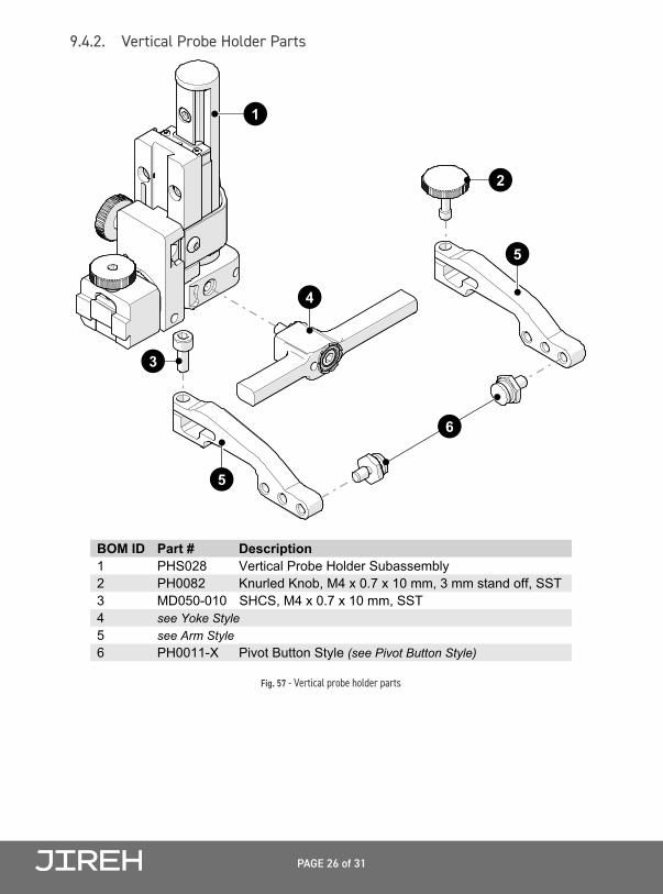
9.4.2. Vertical Probe Holder Parts
5
2
1
3
6
4
5
BOM ID Part # Description1 PHS028 Vertical Probe Holder Subassembly23
see Arm Style
45
see Yoke Style
6
MD050-010 SHCS, M4 x 0.7 x 10 mm, SSTPH0082 Knurled Knob, M4 x 0.7 x 10 mm, 3 mm stand off, SST
PH0011-X Pivot Button Style (see Pivot Button Style)
Fig. 57 - Vertical probe holder parts

PAGE 27 of 31 BG0088 Rev 05.2
9.5. Probe Holder Components
9.5.1. Spring-Loaded Arm Style
9.5.2. Slip Joint and Vertical Probe Holder Arm Style
9.5.3. Slip Joint and Vertical Probe Holder Yoke Style
9.5.4. Swing Arm Style
NOTE: Short swing arm only compatible with standard yoke style.
A BArm Style
ShortStandard PH0089PH0090
Part # Arm Style Part Number
Fig. 58 - Spring-loaded probe holder arm selection
A BC DE F
G H
Arm Style
Short, Flat
Long, Flat Standard, Drop
Short, Drop Long, Drop
Standard, Extra-Drop Short, Extra-Drop
Standard, Flat PH0089
PH0099 PH0093
I JExtra-Short, Flat Extra-Short, DropPH0159 PH0161
PH0092 PH0094
PH0095PH0096
PH0090
Part # Arm Style Part #
Part #
BG0038-15
BG0038-05
15 cm (5.91 in)
5 cm (1.97 in)
BG0038-35
BG0038-25
35 cm (13.78 in)
25 cm (9.84 in)
BG0038-55
BG0038-45
55 cm (21.65 in)
45 cm (17.72 in)
Length Part #
BG0038-20
BG0038-10
20 cm (7.87 in)
10 cm (3.94 in)
BG0038-40
BG0038-30
40 cm (15.75 in)
30 cm (11.81 in)
BG0038-50 50 cm (19.69 in)
Length
Part #
BG0090-15
BG0090-05
15 cm (5.91 in)
5 cm (1.97 in)
BG0090-35
BG0090-25
35 cm (13.78 in)
25 cm (9.84 in)
BG0090-55
BG0090-45
55 cm (21.65 in)
45 cm (17.72 in)
Length Part #
BG0090-20
BG0090-10
20 cm (7.87 in)
10 cm (3.94 in)
BG0090-40
BG0090-30
40 cm (15.75 in)
30 cm (11.81 in)
BG0090-50 50 cm (19.69 in)
Length
01 0203 04
Pivot Hole Size
5.0 mm (0.20 in)
2.7 mm (0.11 in) 9.5 mm (0.38 in)
8.0 mm (0.32 in) Olympus TOFD
Sonatest DAAH PA -
Olympus PA
06 0708 09
2.3 mm (0.09 in)
Conical Head 5 mm (0.20 in) Internal
3.0 mm (0.12 in) -
- Zetec PA/TOFD
-
Wedge Type Pivot Hole Size Wedge Type
WideStandard PHS048 8.3 cm (3.26 in) 12.2 cm (4.79 in)
LengthYoke StyleYoke Style Part #
PHS047
Part #Length
S W
LongShort PH0069 4.1 cm (1.61 in) 4.6 cm (1.81 in)
LengthSwing Arm Style Swing Arm StylePart #
PH0100
Part #Length
S WYoke Style
WideStandard PHS063PHS052
Part #
6.3 cm (2.47 in)
Length
7.9 cm (3.06 in)
LengthYoke Style Part #
BC
ConnectorType
Olympus - Focus LT / Zetec Z-Scan / Eddyfi Ectane 2
Olympus - OmniScan MX / Zetec - ZIRCON, TOPAZ
Company/Instrument
GM
ConnectorType
GE - USM Vision
Sonotron - Isonic
DF TD - Focus Scan, Handy Scan, Pocket Scan
Olympus - OmniScan MX2, OmniScan SX U Sonatest - VEO, PRISMA
Company/Instrument
V Pragma PAUT 16/128, PragmaLite / Pragma UT400
Fig. 59 - Slip joint and vertical probe holder arm selection
A BC DE F
G H
Arm Style
Short, Flat
Long, Flat Standard, Drop
Short, Drop Long, Drop
Standard, Extra-Drop Short, Extra-Drop
Standard, Flat PH0089
PH0099 PH0093
I JExtra-Short, Flat Extra-Short, DropPH0159 PH0161
PH0092 PH0094
PH0095PH0096
PH0090
Part # Arm Style Part #
Part #
BG0038-15
BG0038-05
15 cm (5.91 in)
5 cm (1.97 in)
BG0038-35
BG0038-25
35 cm (13.78 in)
25 cm (9.84 in)
BG0038-55
BG0038-45
55 cm (21.65 in)
45 cm (17.72 in)
Length Part #
BG0038-20
BG0038-10
20 cm (7.87 in)
10 cm (3.94 in)
BG0038-40
BG0038-30
40 cm (15.75 in)
30 cm (11.81 in)
BG0038-50 50 cm (19.69 in)
Length
Part #
BG0090-15
BG0090-05
15 cm (5.91 in)
5 cm (1.97 in)
BG0090-35
BG0090-25
35 cm (13.78 in)
25 cm (9.84 in)
BG0090-55
BG0090-45
55 cm (21.65 in)
45 cm (17.72 in)
Length Part #
BG0090-20
BG0090-10
20 cm (7.87 in)
10 cm (3.94 in)
BG0090-40
BG0090-30
40 cm (15.75 in)
30 cm (11.81 in)
BG0090-50 50 cm (19.69 in)
Length
01 0203 04
Pivot Hole Size
5.0 mm (0.20 in)
2.7 mm (0.11 in) 9.5 mm (0.38 in)
8.0 mm (0.32 in) Olympus TOFD
Sonatest DAAH PA -
Olympus PA
06 0708 09
2.3 mm (0.09 in)
Conical Head 5 mm (0.20 in) Internal
3.0 mm (0.12 in) -
- Zetec PA/TOFD
-
Wedge Type Pivot Hole Size Wedge Type
WideStandard PHS048 8.3 cm (3.26 in) 12.2 cm (4.79 in)
LengthYoke StyleYoke Style Part #
PHS047
Part #Length
S W
LongShort PH0069 4.1 cm (1.61 in) 4.6 cm (1.81 in)
LengthSwing Arm Style Swing Arm StylePart #
PH0100
Part #Length
S WYoke Style
WideStandard PHS063PHS052
Part #
6.3 cm (2.47 in)
Length
7.9 cm (3.06 in)
LengthYoke Style Part #
BC
ConnectorType
Olympus - Focus LT / Zetec Z-Scan / Eddyfi Ectane 2
Olympus - OmniScan MX / Zetec - ZIRCON, TOPAZ
Company/Instrument
GM
ConnectorType
GE - USM Vision
Sonotron - Isonic
DF TD - Focus Scan, Handy Scan, Pocket Scan
Olympus - OmniScan MX2, OmniScan SX U Sonatest - VEO, PRISMA
Company/Instrument
V Pragma PAUT 16/128, PragmaLite / Pragma UT400
Fig. 60 - Slip joint and vertical probe holder arm selection
A BC DE F
G H
Arm Style
Short, Flat
Long, Flat Standard, Drop
Short, Drop Long, Drop
Standard, Extra-Drop Short, Extra-Drop
Standard, Flat PH0089
PH0099 PH0093
I JExtra-Short, Flat Extra-Short, DropPH0159 PH0161
PH0092 PH0094
PH0095PH0096
PH0090
Part # Arm Style Part #
Part #
BG0038-15
BG0038-05
15 cm (5.91 in)
5 cm (1.97 in)
BG0038-35
BG0038-25
35 cm (13.78 in)
25 cm (9.84 in)
BG0038-55
BG0038-45
55 cm (21.65 in)
45 cm (17.72 in)
Length Part #
BG0038-20
BG0038-10
20 cm (7.87 in)
10 cm (3.94 in)
BG0038-40
BG0038-30
40 cm (15.75 in)
30 cm (11.81 in)
BG0038-50 50 cm (19.69 in)
Length
Part #
BG0090-15
BG0090-05
15 cm (5.91 in)
5 cm (1.97 in)
BG0090-35
BG0090-25
35 cm (13.78 in)
25 cm (9.84 in)
BG0090-55
BG0090-45
55 cm (21.65 in)
45 cm (17.72 in)
Length Part #
BG0090-20
BG0090-10
20 cm (7.87 in)
10 cm (3.94 in)
BG0090-40
BG0090-30
40 cm (15.75 in)
30 cm (11.81 in)
BG0090-50 50 cm (19.69 in)
Length
01 0203 04
Pivot Hole Size
5.0 mm (0.20 in)
2.7 mm (0.11 in) 9.5 mm (0.38 in)
8.0 mm (0.32 in) Olympus TOFD
Sonatest DAAH PA -
Olympus PA
06 0708 09
2.3 mm (0.09 in)
Conical Head 5 mm (0.20 in) Internal
3.0 mm (0.12 in) -
- Zetec PA/TOFD
-
Wedge Type Pivot Hole Size Wedge Type
WideStandard PHS048 8.3 cm (3.26 in) 12.2 cm (4.79 in)
LengthYoke StyleYoke Style Part #
PHS047
Part #Length
S W
LongShort PH0069 4.1 cm (1.61 in) 4.6 cm (1.81 in)
LengthSwing Arm Style Swing Arm StylePart #
PH0100
Part #Length
S WYoke Style
WideStandard PHS063PHS052
Part #
6.3 cm (2.47 in)
Length
7.9 cm (3.06 in)
LengthYoke Style Part #
BC
ConnectorType
Olympus - Focus LT / Zetec Z-Scan / Eddyfi Ectane 2
Olympus - OmniScan MX / Zetec - ZIRCON, TOPAZ
Company/Instrument
GM
ConnectorType
GE - USM Vision
Sonotron - Isonic
DF TD - Focus Scan, Handy Scan, Pocket Scan
Olympus - OmniScan MX2, OmniScan SX U Sonatest - VEO, PRISMA
Company/Instrument
V Pragma PAUT 16/128, PragmaLite / Pragma UT400
Fig. 61 - Swing arm selection

PAGE 28 of 31
9.5.5. Pivot Button Style
NOTE: Additional probe holder pivot button types available. (contact Jireh Industries Ltd. on page 1)
9.6. Variable Components
9.6.1. Frame Bars
A BC DE F
G H
Arm Style
Short, Flat
Long, Flat Standard, Drop
Short, Drop Long, Drop
Standard, Extra-Drop Short, Extra-Drop
Standard, Flat PH0089
PH0099 PH0093
I JExtra-Short, Flat Extra-Short, DropPH0159 PH0161
PH0092 PH0094
PH0095PH0096
PH0090
Part # Arm Style Part #
Part #
BG0038-15
BG0038-05
15 cm (5.91 in)
5 cm (1.97 in)
BG0038-35
BG0038-25
35 cm (13.78 in)
25 cm (9.84 in)
BG0038-55
BG0038-45
55 cm (21.65 in)
45 cm (17.72 in)
Length Part #
BG0038-20
BG0038-10
20 cm (7.87 in)
10 cm (3.94 in)
BG0038-40
BG0038-30
40 cm (15.75 in)
30 cm (11.81 in)
BG0038-50 50 cm (19.69 in)
Length
Part #
BG0090-15
BG0090-05
15 cm (5.91 in)
5 cm (1.97 in)
BG0090-35
BG0090-25
35 cm (13.78 in)
25 cm (9.84 in)
BG0090-55
BG0090-45
55 cm (21.65 in)
45 cm (17.72 in)
Length Part #
BG0090-20
BG0090-10
20 cm (7.87 in)
10 cm (3.94 in)
BG0090-40
BG0090-30
40 cm (15.75 in)
30 cm (11.81 in)
BG0090-50 50 cm (19.69 in)
Length
01 0203 04
Pivot Hole Size
5.0 mm (0.20 in)
2.7 mm (0.11 in) 9.5 mm (0.38 in)
8.0 mm (0.32 in) Olympus TOFD
Sonatest DAAH PA -
Olympus PA
06 0708 09
2.3 mm (0.09 in)
Conical Head 5 mm (0.20 in) Internal
3.0 mm (0.12 in) -
- Zetec PA/TOFD
-
Wedge Type Pivot Hole Size Wedge Type
WideStandard PHS048 8.3 cm (3.26 in) 12.2 cm (4.79 in)
LengthYoke StyleYoke Style Part #
PHS047
Part #Length
S W
LongShort PH0069 4.1 cm (1.61 in) 4.6 cm (1.81 in)
LengthSwing Arm Style Swing Arm StylePart #
PH0100
Part #Length
S WYoke Style
WideStandard PHS063PHS052
Part #
6.3 cm (2.47 in)
Length
7.9 cm (3.06 in)
LengthYoke Style Part #
BC
ConnectorType
Olympus - Focus LT / Zetec Z-Scan / Eddyfi Ectane 2
Olympus - OmniScan MX / Zetec - ZIRCON, TOPAZ
Company/Instrument
GM
ConnectorType
GE - USM Vision
Sonotron - Isonic
DF TD - Focus Scan, Handy Scan, Pocket Scan
Olympus - OmniScan MX2, OmniScan SX U Sonatest - VEO, PRISMA
Company/Instrument
V Pragma PAUT 16/128, PragmaLite / Pragma UT400
Fig. 62 - Probe holder button selection
A BC DE F
G H
Arm Style
Short, Flat
Long, Flat Standard, Drop
Short, Drop Long, Drop
Standard, Extra-Drop Short, Extra-Drop
Standard, Flat PH0089
PH0099 PH0093
I JExtra-Short, Flat Extra-Short, DropPH0159 PH0161
PH0092 PH0094
PH0095PH0096
PH0090
Part # Arm Style Part #
Part #
BG0038-15
BG0038-05
15 cm (5.91 in)
5 cm (1.97 in)
BG0038-35
BG0038-25
35 cm (13.78 in)
25 cm (9.84 in)
BG0038-55
BG0038-45
55 cm (21.65 in)
45 cm (17.72 in)
Length Part #
BG0038-20
BG0038-10
20 cm (7.87 in)
10 cm (3.94 in)
BG0038-40
BG0038-30
40 cm (15.75 in)
30 cm (11.81 in)
BG0038-50 50 cm (19.69 in)
Length
Part #
BG0090-15
BG0090-05
15 cm (5.91 in)
5 cm (1.97 in)
BG0090-35
BG0090-25
35 cm (13.78 in)
25 cm (9.84 in)
BG0090-55
BG0090-45
55 cm (21.65 in)
45 cm (17.72 in)
Length Part #
BG0090-20
BG0090-10
20 cm (7.87 in)
10 cm (3.94 in)
BG0090-40
BG0090-30
40 cm (15.75 in)
30 cm (11.81 in)
BG0090-50 50 cm (19.69 in)
Length
01 0203 04
Pivot Hole Size
5.0 mm (0.20 in)
2.7 mm (0.11 in) 9.5 mm (0.38 in)
8.0 mm (0.32 in) Olympus TOFD
Sonatest DAAH PA -
Olympus PA
06 0708 09
2.3 mm (0.09 in)
Conical Head 5 mm (0.20 in) Internal
3.0 mm (0.12 in) -
- Zetec PA/TOFD
-
Wedge Type Pivot Hole Size Wedge Type
WideStandard PHS048 8.3 cm (3.26 in) 12.2 cm (4.79 in)
LengthYoke StyleYoke Style Part #
PHS047
Part #Length
S W
LongShort PH0069 4.1 cm (1.61 in) 4.6 cm (1.81 in)
LengthSwing Arm Style Swing Arm StylePart #
PH0100
Part #Length
S WYoke Style
WideStandard PHS063PHS052
Part #
6.3 cm (2.47 in)
Length
7.9 cm (3.06 in)
LengthYoke Style Part #
BC
ConnectorType
Olympus - Focus LT / Zetec Z-Scan / Eddyfi Ectane 2
Olympus - OmniScan MX / Zetec - ZIRCON, TOPAZ
Company/Instrument
GM
ConnectorType
GE - USM Vision
Sonotron - Isonic
DF TD - Focus Scan, Handy Scan, Pocket Scan
Olympus - OmniScan MX2, OmniScan SX U Sonatest - VEO, PRISMA
Company/Instrument
V Pragma PAUT 16/128, PragmaLite / Pragma UT400
Fig. 63 - Frame bar selection

PAGE 29 of 31 BG0088 Rev 05.2
Chapter 10
DISPOSAL
WEEE Directive In accordance with European Directive on Waste Electrical and Electronic Equipment (WEEE), this symbol indicated that the product must not be disposed of as unsorted municipal waste, but should be collected separately. Refer to Jireh Industries for return and/or collection systems available in your country.

PAGE 30 of 31
Chapter 11
LIMITED WARRANTY
WARRANTY COVERAGEJireh Industries warranty obligations are limited to the terms set forth below: Jireh Industries Ltd. (“Jireh”) warrants this hardware product against defects in materials and workmanship for a period of THREE (3) YEARS from the original date of purchase. If a defect exists, at its option Jireh will (1) repair the product at no charge, using new or refurbished replacement parts, (2) exchange the product with a product that is new or which has been manufactured from new or serviceable used parts and is at least functionally equivalent to the original product, or (3) refund the purchase price of the product. A replacement product/part assumes the remaining warranty of the original product or ninety (90) days from the date of replacement or repair, whichever provides longer coverage for you. When a product or part is exchanged, any replacement item becomes your property and the replaced item becomes Jireh’s property. When a refund is given, your product becomes Jireh’s property.
OBTAINING WARRANTY SERVICETo utilize Jireh’s warranty service you must ship the product, at your expense, to and from Jireh Industries. Before you deliver your product for warranty service you must phone Jireh and obtain an RMA number. This number will be used to process and track your product. Jireh is not responsible for any damage incurred during transit.
EXCLUSIONS AND LIMITATIONSThis Limited Warranty applies only to hardware products manufactured by or for Jireh Industries. This warranty does not apply: (a) to damage caused by accident, abuse, misuse, misapplication, or non-Jireh products; (b) to damage caused by service (including upgrades and expansions) performed by anyone who is not a Jireh Authorized Service Provider; (c) to a product or a part that has been modified without the written permission of Jireh.
Jireh Industries Ltd. 53158 Range Rd 224
Ardrossan AB T8E 2K4 Canada
Phone: 780-922-4534jireh.com

PAGE 31 of 31 BG0088 Rev 05.2
All brands are trademarks or registered trademarks of their respective owners and third party entities.Changes or modifications to this unit or accessories, not expressly approved by the party responsible for compliance could void the user’s authority to operate the equipment.All specifications are subject to change without notice.
© 2018 - 2020 Jireh Industries Ltd.

Jireh Industries Ltd.53158 Range Road 224
Ardrossan, AlbertaCanadaT8E 2k4
780-922-4534jireh.com