bha & drilling parameters design for …theargeo.org/presentations/drilling/bha and drilling...
TRANSCRIPT

BHA & DRILLING PARAMETERS
DESIGN FOR DEVIATION CONTROL
IN MENENGAI DIRECTIONAL WELLS (ARGeo C6 31st Oct. – 6th Nov. 2016)
Abraham W. Khaemba
Denis M. Onchiri

Outline
• Introduction
• Menengai Wells Design
• Drilling MW21A Summary
• Drilling MW09B Summary
• Findings from drilling the Wells
• Recommendations on BHA & Drilling parameters design
• Conclusion
INTRODUCTION
• In directional drilling, the drilling target and the casing
setting depths are established then the three dimensional
geometric shape of the well is determined.
• Typically this will be either a ‘J’ or an ‘S’ shaped well
profile.
• ‘J’ well shape is normally comprised of an initial vertical
section to the ‘kick-off’ point (KOP); followed by a curve
of constant radius determined by the "rate of build" to the
end of build (EOB), following by a straight section hole at
a constant angle from the vertical

INTRODUCTION
• The ‘S’ well shape is normally comprised of an
initial vertical section to the KOP, followed by a
‘build section’ with a curve of constant radius,
followed by a straight section hole at a constant
angle from the vertical: (at the maximum drift
angle); the drill bit is then allowed to fall (from
the start of fall point (SOF) at a constant ‘rate of
fall’ to the final drift angle, at the end of fall point
(EOF); followed by a straight of hole with the
drift angle being maintained at the final angle of
inclination

Menengai Wells Design
• S Profile
• Kick off below
Anchor Casing
• Build & hold
inclination angle in
12½″ hole Section
• Drop then hold the
inclination angle in
the 8½″ hole
section
Wells Data
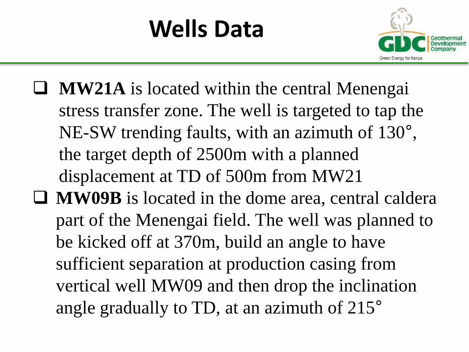
MW21A is located within the central Menengai
stress transfer zone. The well is targeted to tap the
NE-SW trending faults, with an azimuth of 130°,
the target depth of 2500m with a planned
displacement at TD of 500m from MW21
MW09B is located in the dome area, central caldera
part of the Menengai field. The well was planned to
be kicked off at 370m, build an angle to have
sufficient separation at production casing from
vertical well MW09 and then drop the inclination
angle gradually to TD, at an azimuth of 215°

Drilling MW21A Summary
• The well was kicked off at 402m and drilled with
steerable BHA to 606m.
• Rotary building assembly was used to a depth of
800m
• Drilled with a locked up BHA with a near bit
stabilizer and two string stabilizers, and then run a
pendulum BHA to drop the angle slightly
• Survey at a depth of 870m, indicated the well was
off track, and steerable BHA was run to correct the
Inclination & Azimuth
Drilling MW21A Summary
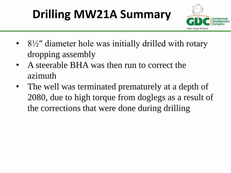
• 8½″ diameter hole was initially drilled with rotary
dropping assembly
• A steerable BHA was then run to correct the
azimuth
• The well was terminated prematurely at a depth of
2080, due to high torque from doglegs as a result of
the corrections that were done during drilling
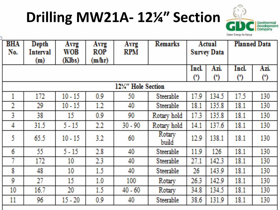
Drilling MW21A- 12¼″ Section

Drilling MW21A- 8½″ Section

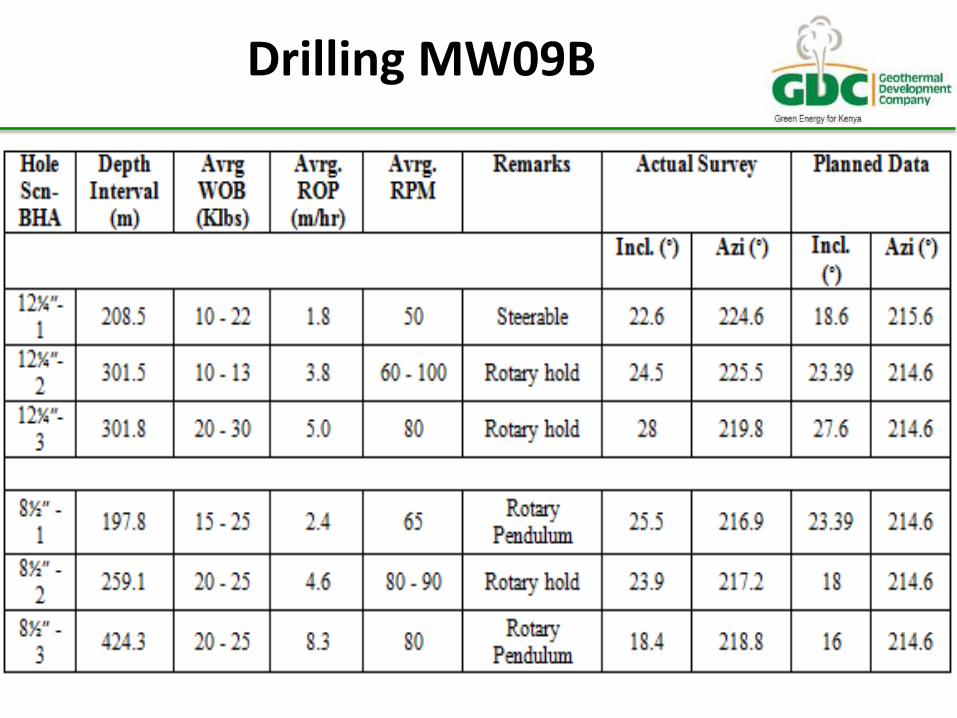
Drilling MW09B Summary
• The well was kicked off at 370m with a steerable
BHA to 578m
• A rotary locked up assembly was used to 878m
before drilling with a dropping assembly to 9⅝″ casing depth
• The 8½″ hole section was drilled with a dropping assembly for a depth 200m before running a holding assembly for a depth of 250m
• Finally a dropping assembly was used to the well TD
Drilling MW09B

Findings From Drilling of the Wells
• Drilling of MW21A took longer than drilling of MW09B
• MW21A had 11 BHA configurations for the 12¼″ hole
section while MW09B had only 3 for the same section
• For the 8½″ section, MW21A had 5 BHA configurations,
for MW09B, 3 configurations were enough for the entire
hole section
• Drilling challenge; High torque was experienced in
MW21A but not in MW09B
• MW21A, had 9 steerable BHA’s while MW09B had only
1 steerable BHA

Recommendations on BHA and Drilling Parameters Design
• From the drilling of the two directional wells, its
recommended that four (4) well designed BHA’s are
sufficient to drill directional wells at Menengai from kick
off to completion of the well.
• This will save trip time and increase rate of penetration
while drilling and hence significantly reducing the costs of
directional wells. The recommended BHA’s are;
• Steerable BHA for kicking off the well for the build section.
• Lock up 12¼″ BHA for the hold section.
• 12¼″ Pendulum BHA to be run at the end of the hold
section to production casing depth.
• 8½″ Dropping assembly for the main hole section
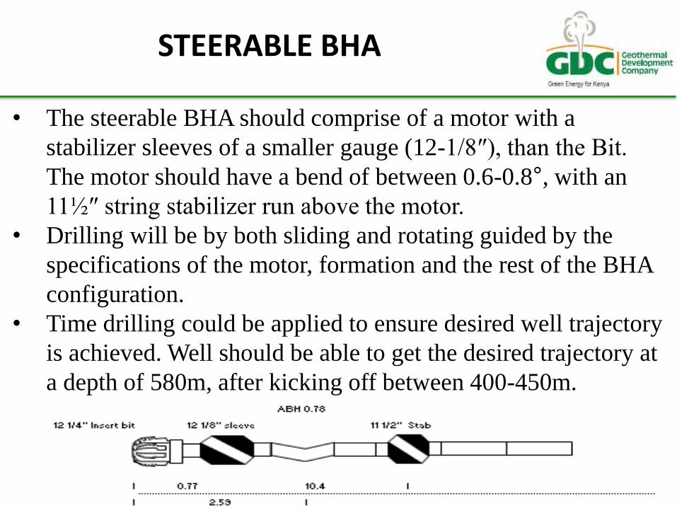
STEERABLE BHA
• The steerable BHA should comprise of a motor with a
stabilizer sleeves of a smaller gauge (12-1/8″), than the Bit.
The motor should have a bend of between 0.6-0.8°, with an
11½″ string stabilizer run above the motor.
• Drilling will be by both sliding and rotating guided by the
specifications of the motor, formation and the rest of the BHA
configuration.
• Time drilling could be applied to ensure desired well trajectory
is achieved. Well should be able to get the desired trajectory at
a depth of 580m, after kicking off between 400-450m.

LOCK UP ASSEMBLY- 12¼″ HOLE
• This BHA should hold both the inclination and azimuth
angles. Its desired to run a near bit stabilizer and two string
stabilizers with the outside diameters decreasing slightly all
the way from the bit to the last stabilizer up the BHA.
• Parameters to be used with this BHA should be determined by
a performing a drill off test.
• High weights should be used with moderate rotation speeds of
between 50-60 revolutions per minute. One bit run is sufficient
to drill the hold section that could be between 200-400 metres.

12¼″ PENDULUM ASSEMBLY
• This BHA mainly comprises of two string stabilizers whose
positioning varies.
• The BHA is run at the end of hold section for minor
corrections to be done before the production casing.
• If a slight build in angle is required more bit weight is used
while if a slight drop is required, less weight will be applied.
• Higher rotation speed of between 80-100 revolutions per
minute can be used with this BHA configuration

DROPPING ASSEMBLY-8½″ HOLE
The configuration is similar pendulum BHA for the previous
hole section. For this section, the angle should drop slightly
all the way to the total depth of the well. Weight of up to 80%
of the BHA weight below the jar should be used with high
rotation speeds of 100 revolutions per minute. The
positioning of the stabilizers will be determined by the
surveys taken during drilling and changed during bit change.
Figure 5: 8½” Dropping BHA
CONCLUSION
• Full gauge near bit stabilizer gives maximum building
tendency
• 2nd stabilizer changes rate of build up & reduces tendency
of directional change due to formation influence
• High hydraulic horsepower hinders building angle in soft
formation
• Slow RPM and high bit weights helps build angle
• The pendulum effect is higher if weight of drill collars
below stabilizer is increased
• Higher distance of stabilizer from the bit increases the rate
of dropping the inclination angle.

THANK YOU