bhutan broadcasting service corporation - · pdf filebhutan broadcasting service corporation...
TRANSCRIPT

P.O. Box 101, Thimphu, Bhutan, +975 (02) 323071,323072, 322866, 322533
Fax + 975 (02) 323073 E-mail [email protected]>
BHUTAN BROADCASTING SERVICE CORPORATION
Tender No: BBSC/TECH-Trans (Infrastructure)/2106
ANNEXURE-I
Technical Specification for BBSC FM/TV Station Infrastructure Development SCOPE OF WORK: The scope of works includes Supply, Installation, Testing & Commissioning of BBSC Transmission Infrastructure “Construction of Towers, shelter, power system and fencing”. GENERAL
1. Documents and articles necessary for approval by the local approving authorities are as shown in the following table:
SL ITEMS TIME FOR SUBMISSION QUANTITY REQUIRE
a Test certificates and report
Whenever occasion arises 2 All except for fencing
b Shop drawings and manufacturer’s drawings
Whenever occasion arises 2 Shop drawing only for tower, rest all need. fencing drawing will be provided by purchaser
c Samples and catalogues
Whenever occasion arises As specified in document
All except for fencing
d Any other documents
Whenever demanded by The Purchaser / Local Approving authorities.
As specified in document
All
e Foundation drawing
With bid document As specified in document
Only Shelter and tower
The outline of the aforesaid documents and articles are as follows:
a. Test Certificates and Reports Test certificates and reports on the tests carried out at factories, laboratories or at the Sites shall be submitted occasionally. Not only the tests specified in this specification but also the tests required by the supplier shall be carried out according to the instructions.
b. Shop Drawings and Manufacturer’s Drawings.
The drawings specified in this Specification shall be submitted according to the Purchaser’s instructions. The supplier shall submit revised drawings if the Purchaser so requires. No work shall commence before getting the Purchaser’s approval to the relevant shop and manufacturer’s drawings.
c. Samples and Catalogues. Samples and catalogues shall be specified in this specification. d. Any other Documents. Any other documents specified in this Chapter or the documents
directed by the Purchaser during the progress of the Civil Works shall be submitted.
2. Modification of Materials and Methods of Works Except in cases where the modification of design is required by Purchaser or the approving authorities, the supplier shall strictly comply with the approved Specifications and Drawings. If the Supplier requires modification of designs or alteration of materials and methods of works specified in this document, he shall submit the report stating the reasons for the modifications and the details of such modifications clearly, comprehensively and correctly besides submitting samples of modified materials with relevant specifications from the manufacturers. No modified works shall be carried out before getting the Purchaser’s

P.O. Box 101, Thimphu, Bhutan, +975 (02) 323071,323072, 322866, 322533
Fax + 975 (02) 323073 E-mail [email protected]>
BHUTAN BROADCASTING SERVICE CORPORATION
consent. If the bidder feels that the design specified by the Purchaser is inadequate, an alternative design may be proposed at no additional cost to the Purchaser.
A. TECHNICAL SPECIFICATIONS AND DESIGN OF TOWER
Design Requirements The Supplier is required to design the towers of 3-legged triangular self supporting tower for the height of 25meter considering the following factors:
1. General
1.1 The supplier shall establish the design conditions of the antenna supporting structures and all the other related facilities to carry out the structural load calculations and to prepare the drawings and descriptions.
1.2 Before commencement of the works the supplier shall submit the following information for approval by the Purchaser: a. The list of standards, which is intends to apply in accordance with this Specification. b. Grade of steel materials to be used including reinforcing bars and their allowable design
stress. c. Outline of design criteria for structural calculations based on:
i. Wind load and, ii. Seismic load where required. iii. Dead load. iv. Twist, sway and displacement. v. Snow load.(Gagar and khando phung station) vi. Stress analysis for reinforced concrete of the foundation.
d. Allowable bearing strength of soil and, if required, statement of the soil bearings described in this Specification.
e. Typical schematic drawings showing outline of the proposed facilities and structures. f. Climatic conditions of each site including items relating to wind load, ice coating load and
seismic load. g. Outline of geographical condition of each site h. Detail time schedule of execution of the design. i. Any other important items to be determined before structural calculation and preparing
drawings and specifications.
1.3 After completion of preparation of the drawings and descriptions, the following information / details shall be submitted in two (2) copies to the Purchaser for approval: a. Explanation on Design, including:
List of the standards applied.
Climatic conditions of each site including items relating wind load, ice coating load and seismic load.
Type, size, dimensions weight, quantity and positions of antennas to be mounted on the antenna supporting structure, including future plan.
b. Structural calculations for the facilities structures, showing:
Calculation of load, viz. dead load, including ice coating load, wind load and seismic load where required.
c. Stress analysis and section designs, including:
Line diagram showing each member stress corresponding to various loading conditions.
Tables on load carrying members, listing sizes, lengths, slenderness ratios, allowable stress, actual stress and the sizes and members of bolts at each connection.

P.O. Box 101, Thimphu, Bhutan, +975 (02) 323071,323072, 322866, 322533
Fax + 975 (02) 323073 E-mail [email protected]>
BHUTAN BROADCASTING SERVICE CORPORATION
Local stress analysis and section design of the structure at the parts on which the antennas and the appurtenances are to be mounted (including adjacent members affected).
Maximum twist, sway and displacement of the main supporting structure in the worst loading condition.
d. Structural calculations for the foundations, including:
Load on the foundation by the facilities structure in the various loading conditions.
Calculations of stability against uplift, shearing and down-thrust stresses caused by the load.
Calculations for the reinforcement. e. Drawings, showing:
Layout of the foundations and facility’s structures station wise, details of the foundations and facility’s structures station wise, and position, dimension and type of the antennas to be mounted on the antenna supporting structure.
1.4 Immediately after approval by the Purchaser, the supplier shall submit three (2) sets of the approved explanation on design, structural calculations, drawings and descriptions.
1.5 The approval of the design conditions, calculations, drawings and descriptions shall not relieve the supplier from his responsibility for the accuracy, adequacy and reliability of the facilities to be constructed.
1.6 Where necessity of change of the approved design conditions, calculations, drawings and / or description arises, these shall be approved by the Purchaser.
2. Structural Design 2.1 General
a. Unless otherwise specified, the antenna supporting structure shall be self-supporting with self supporting type and the foundation shall be of reinforced concrete.
b. Any stress of component of facilities, of steel, bolt, reinforcing bar and concrete shall not exceed allowable stress of material specified in the Standard.
c. The design for steel structure shall be based on the following concept and assumption in-case if the tower structure to be constructed:
i. Steel structure shall be regarded as an elastic body. ii. Steel structure shall be analyzed as a space framework. However, in common trussed
structures, the stress may be calculated as a plane, truss of which the members are frame din one plane, substituting the space framework, and furthermore, where the common truss has small inclination, the truss may be calculated on the projection of the truss on the vertical plane. In this case, the following shall be taken into consideration:
Where the inclination of the truss is not uniform, interaction between two inclination
Other influence caused by construction of the plane trusses as a space framework.
iii. Neither the stress caused by dead load including ice coating load, nor the stress resulting from the combined load of dead load and wind load or seismic load shall exceed allowable stress of the materials specified in the Standard.
d. The stress analysis may be carried out by means of electronic computer subject to applying the proven stress analysis program.
e. While designing 3-Legged Self supporting Towers of 25M a maximum weight for each section member shall not exceed 40Kg/section-leg to ease head load transportation burden to some of difficult sites. While the weight of section member above 25M tower shall not exceed 50kg/section.
2.2 Loads on Facility’s Structure a. Dead Load

P.O. Box 101, Thimphu, Bhutan, +975 (02) 323071,323072, 322866, 322533
Fax + 975 (02) 323073 E-mail [email protected]>
BHUTAN BROADCASTING SERVICE CORPORATION
Dead load means the dead weight of the antenna supporting structure and all other facility’s structure, all appurtenances and other such items as antennas, which are to be mounted on the main supporting structure. Where required, dead weight of the ice, which is expected to coat on all members of the antenna supporting structure and all other facility’s structure, the appurtenances, antenna, etc., shall be included in the dead load. At sites over 2,500 meters above sea level, antenna supporting structures, antennas and all other facilities shall be considered for ice coating load. Unless otherwise specified, radius thickness of the ice coating and density of the ice may be assumed as 10 mm and 0.6 g / cu.cm respectively.
b. Wind Load i. Full calculation shall be taken in the wind load acting on the antenna supporting
structure and all other facilities, the appurtenance and antenna, etc. to be attached on the main supporting structure. The ice coating, if required, shall be included as a part of the projected area for locations over 2,500 meters above sea level.
ii. The combined effects of dead load and wind load shall be taken into calculation in the stress analysis so that the worst stress in all component part can be determined. Where height, direction, size and/or type of the antennas are not specified and they cannot be determined at the stage of structural calculation, these shall be so assumed that they cause the worst effects on the structure when wind load is calculated.
iii. Unless otherwise specified, any formulas, coefficients and factors required for calculation of the wind load shall be in accordance with the standard, or the results of tunnel test as an alternative of the Standard.
iv. For the purpose of design and calculations, the wind speed shall be taken at 180 Km / hour
c. Seismic load
i. Where required to consider, the combined effect of dead load and seismic load shall be taken into the calculation.
ii. Combined effects of seismic load and wind load may not be taken into the calculation. iii. The lateral seismic factor may be assumed as k = 0.1 from the 100 year probability
value of 100 gal given in the maximum expected seismicity distribution map of the world published by the Building Research Institute (Ministry of Construction, Japan) or an equally renowned institute, for the calculation.
d. Soil Bearing Capacity Soil bearing capacity at all the sites is assumed as at least 10 tons / sq.m.
2.3 Twist, Sway and Displacement.
a. Twist means horizontal angular displacement of the main supporting structure at each antenna mounting elevation from no wind load position to worst wind load position. Sway means vertical angular displacement of the central vertical axis at each antenna mounting elevation from its no wind position to the worst wind load position, divided by each corresponding elevation.
b. Unless otherwise specified, twist, sway and displacement shall not exceed the following values:
Twist: 1 deg.
Sway: 1 deg.
Displacement : 1/100
2.4 Welding Materials The electrodes to be used for welding shall be standard products. Appropriate electrodes shall be selected for the type of steel to be welded. Welding materials other than those stipulated above shall be selected according to the method of welding to be employed.
a. Bolt Holes. The diameter of bolt holes shall be larger by 0.5 mm than the diameter of the bolt itself. Anchor bolts shall be secured by using two (2) nuts. For bolts, other than those mentioned
P.O. Box 101, Thimphu, Bhutan, +975 (02) 323071,323072, 322866, 322533
Fax + 975 (02) 323073 E-mail [email protected]>
BHUTAN BROADCASTING SERVICE CORPORATION
above, and for those embedded in concrete proper precaution shall be taken to prevent nut loosening by using either double nuts or spring washers or any other acceptable methods.
2.5 Welding. a. General
This clause applies to the arc welding of structural steel elements. i. In-site welding shall be carried out after inspection of the steel fabrication and
election. ii. The welding shall be done only by qualified and experienced welders.
2.6 Product Inspection a. The products shall be inspected by the Purchaser after it reaches to Purchaser’s specified
sites. b. Faulty portions shall be promptly rectified.
.
3. Antenna Support Structure 3.1 General
a. The antenna supporting structure to be constructed shall consist of foundation, main structure, and appurtenances.
b. All steel materials including bolts and nuts shall confirm to international standards. All materials of antenna supporting structure including other steel members used in the structure shall be coated by hot-dip galvanizing after all fabrication works has been completed.
c. The antenna supporting structures shall be inspected by the Purchaser during the construction as well as after the completion of the construction works.
d. A copy of the final drawings and instructions shall be submitted to the Purchaser promptly after the completion of the antenna supporting structures for the Purchaser’s record.
3.2 Tower Shape a. The towers shall be of triangular shaped lattice self supporting towers, made of tubular
members designed to cater total load of maximum 250kg(Max.) which shall consist of 3 nos. each of TV&FM antenna and VHF communication antenna etc.
b. The towers are to be designed for height 25meters for 3-legged self supporting triangular tower.
c. Tower shall equipped with a variety of accessories, such as working plate forms (mesh type), antenna mounts, safety devices, ladders, obstruction lights, lightning protection kit etc, which can be installed at any desired height and orientation.
d. Antenna Mounting i. Consistent with tower height, towers shall be arranged to support antennas at a number of different levels, 4.0 meters apart, measured vertically. This distance may be altered slightly to fit in with the geometry of the tower bracing.
ii. Each antenna mounting position shall be capable of being served by an access platform located approximately 1 meter below the centre-line of the antenna position it serves.
iii. Mounting platforms shall be provided for all antenna positions, which are to be utilized by the Bidder in meeting the radio system requirements. Mounting platforms are not required for unequipped antenna mounting positions.
iv. Antennas shall be mounted on mounting bars to be attached at each mounting level, at set specified vertical distance apart. This distance shall be specified by the Bidder, but should be typically of the order of 1.5 meters. Three sectored Radio antennas shall be mounted on bars/pipes of 50mm-100mm in diameter and 3000mm in length. In addition, two similar bars/pipes shall be provided below also for mounting bay of antenna.
v. Appropriately sized holes shall be provided in the tower legs at each mounting level for mounting bars to be added as required for future radio systems.
vi. Bidders shall allow for 2 pairs of holes per leg on each face at each mounting level. e. Antenna Feeder Runway

P.O. Box 101, Thimphu, Bhutan, +975 (02) 323071,323072, 322866, 322533
Fax + 975 (02) 323073 E-mail [email protected]>
BHUTAN BROADCASTING SERVICE CORPORATION
i. Each tower shall be equipped with a straight, vertical antenna runway extending from the ground to the top of each tower for the provision of coaxial cable and wave guide feeders as necessary. This runway shall have provision for future radio system expansion of:
10 cables -16mm Dia.
10 cables/waveguides -28mm Dia. ii. For towers with a central runway, the lower end of the runway shall be set in a concrete foundation laid on a solid base. Typically this would consist of a concrete foundation block approximately 1.0m x 0.4m deep.
iii. The Bidder shall include design details for a suitable sized antenna feeder gantry extending from the tower structure to the equipment building. This gantry shall be of sturdy construction utilizing galvanized steel members and offer some protection to the feeder cables in the event of flying debris in high winds. Feeder cables should preferably be laid on the underside of the gantry.
f. Platforms i. Working platforms shall be provided to allow access to each antenna equipped for the initial installation specified in these bidding documents.
ii. In addition rest platforms shall be provided on all towers where the vertical spacing between working platforms, or the lowest working platform and ground level, exceeds 15 meters. Rest platforms, where practicable, shall be provided at levels, which coincide with the levels of the working platform for antenna mounting positions.
iii. Platform decking shall be of expanded metal mesh, or similar construction, and shall be adequately supported on steel members of appropriate size.
g. Guard Rails i. Platforms shall be provided with handrails at a height of approximately 1 meter above the decking, intermediate rails at approximately 0.5 meter above the decking and kick rails at the decking level.
ii. All rails shall consist of suitably sized rolled steel angle section. iii. Guardrails shall be provided on all platforms and shall be continuous around the outside perimeter and the runway opening of each platform and shall encompass the ladder and ladder guard so that free access to the ladder may be gained from the platforms.
iv. Handrails on platforms shall not be structural members and shall be removable to facilitate the mounting of antennas.
h. Ladders i. Steel ladders with ladder guards shall be provided from ground level to the highest
working platform on each tower. ii. The ladder guard shall be so arranged that at each antenna mounting level, a section
may be removed to provide access to the further platform without having cut to the vertical strips.
iii. Ladder shall, where practicable, continue for a distance of at-least 1 meter above the upper surface of the platform that is served. The stainless shall not, however,, project above the top of a tower.
iv. Ladders, ladders guards and ladders support shall not infringe on the space reserved for antenna feeders.
v. Ladders shall be adequately supported to resist lateral movement. i. Lightning Protection
i. Two lightning discharge rods of height approximately 2.4 meters shall be securely fixed to the top of each tower on diagonally opposite corners.
ii. Each rod shall consist of a steel tube with four 13mm diameter rods of length 0.5 meter (approximately) welded to the top of the tube, disposed equally around the tube and splayed upwards at 45 degrees.
iii. No separate earth conductor need be provided from the discharge rods to ground and it is necessary, therefore, that all bolted connections in the tower should be free from paint

P.O. Box 101, Thimphu, Bhutan, +975 (02) 323071,323072, 322866, 322533
Fax + 975 (02) 323073 E-mail [email protected]>
BHUTAN BROADCASTING SERVICE CORPORATION
and reasonably clean at the time of assembly. This applies particularly to the point of attachment of the discharge rods to the top of the tower.
j. Earthing i. An earthing system, generally to the provisions of internationally accepted standard
shall be provided at each tower. This shall consist of at least one radial earth strap extending from each tower leg, one loop encircling the tower and a separate loop encircling the equipment building.
ii. Particular attention shall be paid to the bonding of earthing straps to tower, runway, gantry and building steelwork.
iii. Earthing strap shall consist of pure copper of nominal dimensions 3cm x 2.5 cm. iv. The completed earth system shall have a resistance of less than 2 ohms, when
measured with a specific earth resistance-measuring instrument. 3.3 Complete Tower
a. Each erected tower, under conditions of negligible wind, shall not deviate from the vertical position by more than one-eighth of one percent of its height. Each erected tower, under conditions of negligible wind, shall be straight within 25mm of the nominal geometric position.
b. Each erected tower shall be free of inherent twist. c. Where bolts are placed in a generally vertical position, the bolt heads shall be uppermost.
3.4 Lighting a. Where tower lighting is required the tower shall be equipped with suitable air navigation
warning lighting. b. Two 100 watt weather-proof incandescent globes shall be installed at the tower top. c. Operation shall be from 230 volt AC supply and all power conduits shall be of galvanized iron
construction. PVC or other plastic conduit is not acceptable. 3.5 Foundations:
a. The foundations for the towers shall be constructed by successful bidder. b. The bidder shall submit detailed design of the tower foundations. c. The foundation design should be submitted along with the bid document based on the
assumption that the load bearing capacity of the soil at all the sites is 10 ton / sqm. d. All necessary Anchor bolts and templates shall be provided by the contractor.
3.6 Additional Information: a. The weight and base details shall be as under:
Tower Ht=25mtrs,
Base Size (Approx) for 3 legged triangular tower=3500mm (approx)
Weight for 3-legged tower=4500KG (approx) Superstructure: Tower has a tapering structure except for the top 7.5m. *Note: Weight of tower is inclusive of all parts of Superstructure (including the weight of MW antennas mounting arrangement i.e. antenna fixtures, Horizontal cable Tray (6 m) along with foundation Bolts &Templates) and must not be less than the weights mentioned above.
b. The bidder must adhere to following Specification in order to qualify for the supply of Tower: i. Material specification: MS angles of grade ‘A’ as Per IS: 2062 (1999) with latest amendment
and IS: 808(1989) shall he used. All MS angles are to be hot dip galvanized as per IS: 4759(1996), Standard zinc for galvanizing should conform to IS: 13229 (1991) or 1S:209(1992).
ii. Gusset /Splice Plates: MS of grade A’ is per IS: 2062 (1999) with latest amendments and all the plates are hot dip galvanized as per IS: 4759(1996). Standard zinc for galvanizing should conform to IS: 13229 (1991) or 1S:209(1992).
iii. Nuts, Bolts & Washers: Nuts & Bolts of grade 5.6 as per IS 6639(1972)/ IS 1364, IS: 1367 part8 (1992), and Plain washers as per IS 6610 (1972) & spring washers Type B as per IS 3063:1994 shall be used.

P.O. Box 101, Thimphu, Bhutan, +975 (02) 323071,323072, 322866, 322533
Fax + 975 (02) 323073 E-mail [email protected]>
BHUTAN BROADCASTING SERVICE CORPORATION
B. TECHNICAL SPECIFICATIONS FOR PREFABRICATED SHELTER
1. General 1.1 Requirement of a shelter:
a. Closed Chamber. b. Heat Resistant. c. Weather Resistant. d. Sound / Noise Insulation. e. Sealed from external environment. f. Easy to install
1.2 The bidder shall propose weatherproof prefabricated shelters for housing the Broadcasting
equipment including power supply facilities. 1.3 The enclosures shall be mounted on concrete footings at least 2.5 feet above ground level.
Proper steps materials (step ladder made of galvanized steel) shall be supplied for easy access to the shelter.
1.4 The enclosures shall be, preferably, fabricated from high-grade plastic/PVC/other similar lightweight materials with metal sandwich. The materials used for the prefabricated enclosure shall be fire resistant and shall not corrode with age in outdoor installations.
1.5 The enclosure/shelter shall be designed to provide ventilation to the equipment while preventing moisture build-up inside. All materials required to shield the ventilation holes (window shade, sealing materials) should be included in the supply.
1.6 It shall be extremely robust, corrosion resistant, high seismic resistance, wind & dust proof with thermal insulation.
1.7 It shall offer extruded aluminium alloy C-rails for a multipurpose user-friendly mounting arrangement for equipment racks and cable trays etc.
1.8 It shall have three way locking system in tandem with a cam profiled wedge (Which pulls the door leaf inside for proper closer) and EPDM gasket to make the door air and water tight to achieve an IP 54 level protection.
2. Shelter Dimensions: a. Ext.: 3600x2620x2500 (LxWxH in mm) b. Panel with Foam – 60 mm c. Material of Skins – 0.6mm x 0.6mm Pre-coated Steel d. Floor – Ply 20 mm and PVC 2mm.
3. Shelter Accessories: a. Shelter should include power energy meter box, mounted on one of the shelter’s side
wall. The dimension on of energy meter box- 300x400x300 (LxHxW in mm), It should have tow cable hole from below the box.
b. The shelter should include 4x16amp and 2x10amp power point. It should include 63amps main Cut-off DP switch and MCB box including six 16 amp MCB.
c. Shelter should also include one emergency light, external light and 2x 40w fluorescent light.
d. Shelter should include 4 cable ladder, cable hole (roxtech hole), 4. Foundations:
a. The foundations for the shelter shall be constructed by successful bidder. b. The bidder shall submit detailed design and drawing of the shelter foundations. c. All necessary accessories shall be provided by the contractor. d. Shelter foundation should be six legged concrete footing.
5. Ventilation system for Prefab-shelter: 5.1 General Specifications
a. A set of Ventilation system (1 in 1 out) consists of inlet blower (2 fans), exhaust blower (2 Fans), automatically control panel, air filter device and other installation accessories.
b. When the indoor Temp reaches the above “vent ON” temperature, Ventilation controller

P.O. Box 101, Thimphu, Bhutan, +975 (02) 323071,323072, 322866, 322533
Fax + 975 (02) 323073 E-mail [email protected]>
BHUTAN BROADCASTING SERVICE CORPORATION
should check the outside temperature and if found less than the inside temperature then switch ON the inlet and exhaust fans and bring in the cold air from outdoor, exhaust indoor hot air, so that to cool the room and when the indoor Temp reaches lowest point, fans will automatically closed to stop cross-ventilation.
c. In case the outside temperature is higher than inside temperature then system will check the “Aircon ON” temperature, once the inside temperature reaches to “Aircon ON” temperature Ventilation system will switch ON the Air-conditioner if AC mains supply is available. System can handle two Air- conditioners.
d. When indoor humidity reaches the maximum set point then, ventilation system will be shut down and indoor Temp reaches AC start point. AC units start working. Or the humidity reaches <60% the ventilation will start again.
e. System should have the facility to store (event log data) for minimum 1000 events.
5.2 Technical Specification:
Sl No Description Specification
1
Temperature Environment temperature
-10oC to +60 oC
2 Working Voltage 36 to 56VDC
3 Maximum Power Consumption ≤ 1.5 A
4 Ventilation volume ≥800 m3/h
6. Air conditioner (AC) system for prefab-shelter: 6.1 General Requirement: 1.5 Tr Split Air-conditioner should be installed in 5 sites. a. AC Specifications:
i. Capacity : 1.5 ton
ii. Cooling capacity : 5.25kW ± 2%
iii. Electricity in put : 230V/50Hz/Single Phase
iv. Coefficient of performance : 3 (Minimum)
v. Max. Ambient temperature : 480C ± 5%
vi. Moisture removal rate : 2 ± 10% litre/ hour
vii. Air flow rate : 5.6 cmm (Minimum)
viii. Noise level Indoor unit : Less than 45 db
ix. Outdoor unit : Less than 55 db
x. Function modes: Auto/Cool/Fan/Dry – shall have sleep and power saving modes, Auto
restart, speed setting etc.
xi. Other features : - Automated vertical swing for horizontal louvers, Antifreeze thermostat,
Dehumidification
xii. Compressor : Rotary type
xiii. Body surface finish : powder coated/high quality paint finish
xiv. Air filtering unit : Activated carbon cartridge, dust proof and anti bacteria filter Length of
tubing : 15 m or as per the installation requirement
xv. Remote handset : LCD display with night glow
xvi. Voltage Stabilizer : Stabilizer having ISI quality certification and power rating that matches
with the power rating of the A/C unit
b. Line conditioner:
5KVA Line conditioner has to be installed along with Air-conditioner to stabilize the input

P.O. Box 101, Thimphu, Bhutan, +975 (02) 323071,323072, 322866, 322533
Fax + 975 (02) 323073 E-mail [email protected]>
BHUTAN BROADCASTING SERVICE CORPORATION
voltage. a. Input voltage – 150 – 290 V AC b. Output Voltage – 230 V AC +/- 10%
6.2 Surge Protection Devices: Surge protection devices (SPD) should ideally operate instantaneously to divert a surge current to ground with no residual common-mode voltage presented at the equipment terminals. Once the surge current has subsided, the SPD should automatically restore normal operation and reset to a state ready to receive the next surge. Surge protection device should be MOV based technology and should be able to able to handle 50 kA 8/20 micro sec.
C. TECHNICAL SPECIFICATIONS FOR POWER SYSTEM (UPS)
1. General: a. The Power Supply Facilities shall be easy to maintain and be able to keep the required
characteristics stably for at least twelve (12) years. b. The Power supply facilities to be provided shall be composed of the following:
i. VRLA SMF Storage Batteries. ii. SMPS Rectifier iii. Inverter iv. 19 inch battery Rack v. Earthing & Bonding vi. Surge Protection Devices vii. Power Cables
2. Storage Batteries: a. The storage batteries shall be provided with battery racks, necessary connectors,
name plate, battery transparent cover, etc. b. The storage batteries shall be sealed maintenance free (SMF) Valve Regulated
Lead Acid (VRLA) type c. The container shall be strong enough to withstand rough handling. d. Explosion-proof vent plug shall be provided. e. Connectors- Lead Plated Solid Copper Connectors f. Battery 2V/400 AH @ C10 @ 1.75 ECV @ 27 Deg C, -48V DC, 400 AH g. Float Life: 12 + years design life at 27 Deg. C h. Cycle Life: 1200 cycles at 80% DOD at 27 Deg.C i. Self-Discharge: <2% per Month at 27 Deg.C AH j. Layout of batteries shall be such that it permits easy access and sufficient flexibility at
the time of cell unit replacement, and also easy to check the status.
3. SMPS Rectifier: 3.1 General Requirements: This SMPS rectifier system should consists of rectifier modules, standard controller unit and DC Distribution which consists of distribution unit of load and battery. This system should be used as a power supply to charge the battery. 3.2 Features:
a. Easy to install, easy to operate and easy to maintain. b. Wide Input AC Voltage Range of 150 ~ 275 V c. Rectifier Efficiency > 92% d. Extra Low EMI of Rectifier e. High Power Density of Rectifier f. Rectifier should have damage free hot swappable function; the replacement time shall be
less than 1 min. g. Perfect Battery Management with BLVD function. h. Lightning and surge protection device.

P.O. Box 101, Thimphu, Bhutan, +975 (02) 323071,323072, 322866, 322533
Fax + 975 (02) 323073 E-mail [email protected]>
BHUTAN BROADCASTING SERVICE CORPORATION
3.3 Specifications:
a. Input Supply: Single Phase, 230V, 50 Hz b. Output: -48V DC, 120 Amps
3.4 Inverter: a. The Inverter system should be pure sine wave. b. Input Supply – 48 V DC c. Output 230V AC d. Capacity – 2x3kva
D. TECHNICAL SPECIFICATIONS FOR 19 inch EQUIPMENT RACK
1. General Requirements: The 19 inch rack shall be a good quality and powder quoted with black color. Material thickness should be minimum 3 mm thickness. Rack should contain fixed shelf for the installation of equipment
2. Features a. Static load rating of 1400kg b. Seismic rating of 900kg c. Inset corner posts d. Depth adjustable RU marked rails e. Integrated bayed cabinets with simple accessory f. Innovative modular cable management facilities g. Frame designed to allow two or more people to work on installation at once h. Comprehensive range of accessories
3. Materials a. Body – Zinc coated steel b. Frame thickness – 1.6mm c. Rail thickness – 3.0mm d. Surface finish – Powder coated textured matt black
4. Inclusions 1. Frame 2. 2 x RU marked mounting rails 3. Gland plates in roof 4. Bolt down brackets
5. Dimension in (mm) a. height 45 (RU), 2135 b. width 800 and depth 900
6. Accessories a. Fan-kit two unit high speed, axial with integrated with thermostat, should be install on
the top on rack b. Cable management fingers type on the both side of the rack c. Rack shelf heavy duty –fixed type full mount, 750mm deep. quantity 12 shelf d. Two numbers of Vertical power rails, 10x10amp-multi-pin socket and 10x16amp multi-pin
socket. Power socket at the both side of the rack vertically mounted. Rack should also include two numbers of 32 amp DP switch installed at the bottom level of rack. Power Input for both the power rail should be connected through DP switch.
E. TECHNICAL SPECIFICATIONS FOR FENCING
1. Specification for GI barb wire fencing: a. 13 rows & 2 crossed rows of GI Barb Wire 12SWG b. Angle Post 65x65x8mm 2.90m above ground level & 0.5m below ground c. Wiremesh Gate standard frame with angle of size 1.50x2.0m

P.O. Box 101, Thimphu, Bhutan, +975 (02) 323071,323072, 322866, 322533
Fax + 975 (02) 323073 E-mail [email protected]>
BHUTAN BROADCASTING SERVICE CORPORATION
d. Foundation with P.C.C. 1:2:4 of size 400x400mm of height 650mm for angle post e. Perimeter R.R.M. wall in C.M. 1:4 of width 400mm & height 250mm above ground level
and 450mm below ground level. f. P.C.C. 1:3:6 100mm thick for wall foundation and 100mm thick copping for wall g. Stone soling 100mm height for foundation for R.R.M wall only
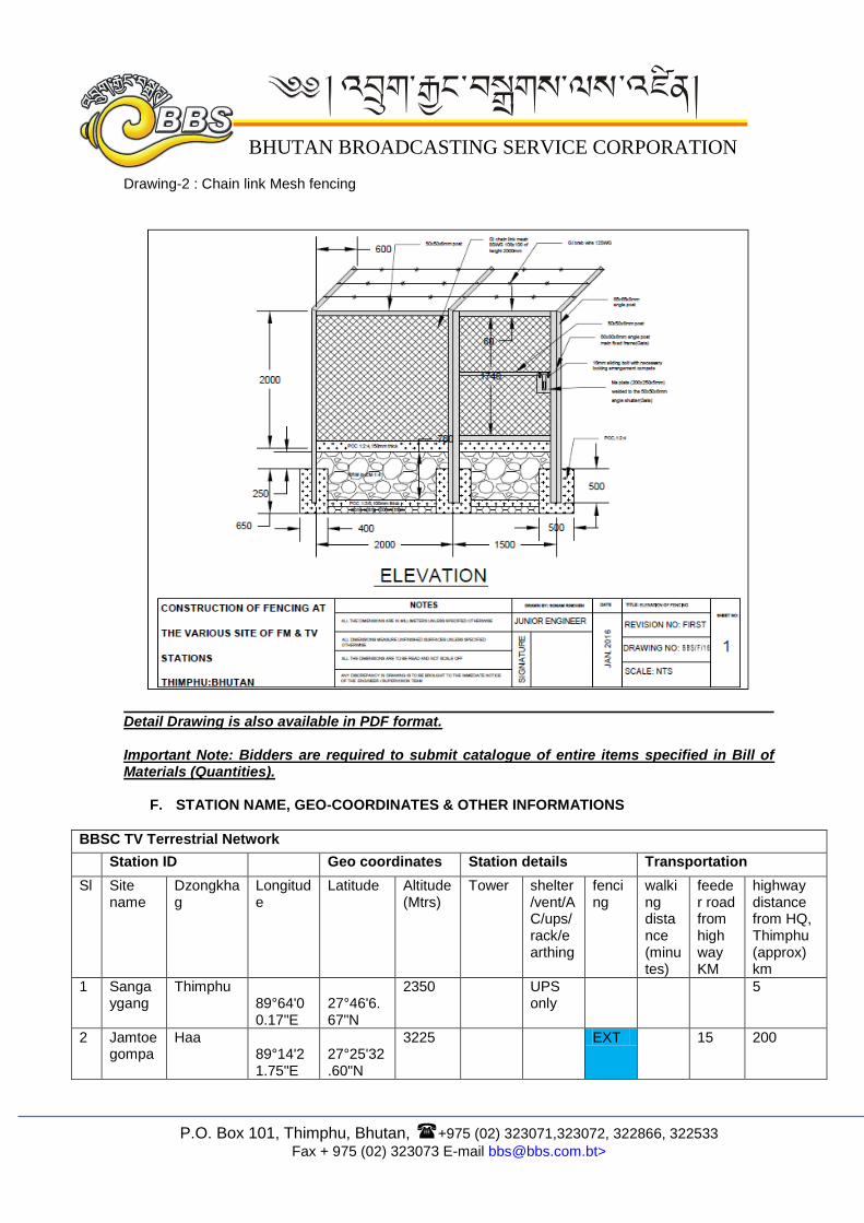
2. Specification for GI Chain Link Mesh Fencing:
a. GI Chain link mesh 8SWG 100x100mm of height 2.00 meters b. 3 rows of GI brab wire 12SWG on top of chain link mesh c. Angle Post 65x65x8mm 2.60m above ground level & 0.50m below ground d. Foundation with P.C.C. 1:2:4 of size 400x400mm of height 650mm for angle post
(length-60mtrs) e. Perimeter R.R.M. wall in C.M. 1:4 of width 400mm & height 250mm above ground level
and 450mm below ground level. f. P.C.C. 1:3:6 100mm thick for wall foundation and 150mm thick copping for wall g. Stone soling 100 mm height for foundation for R.R.M wall only
Drawing-1 : GI barb Wire fencing
P.O. Box 101, Thimphu, Bhutan, +975 (02) 323071,323072, 322866, 322533
Fax + 975 (02) 323073 E-mail [email protected]>
BHUTAN BROADCASTING SERVICE CORPORATION
Drawing-2 : Chain link Mesh fencing
Detail Drawing is also available in PDF format. Important Note: Bidders are required to submit catalogue of entire items specified in Bill of Materials (Quantities).
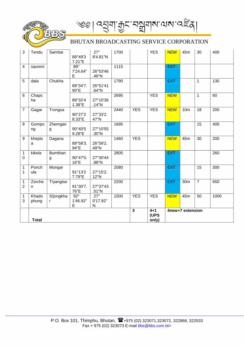
F. STATION NAME, GEO-COORDINATES & OTHER INFORMATIONS
BBSC TV Terrestrial Network
Station ID Geo coordinates Station details Transportation
Sl Site name
Dzongkhag
Longitude
Latitude Altitude (Mtrs)
Tower shelter/vent/AC/ups/ rack/earthing
fencing
walking distance (minutes)
feeder road from high way KM
highway distance from HQ, Thimphu (approx) km
1 Sangaygang
Thimphu 89°64'00.17"E
27°46'6.67"N
2350 UPS only
5
2 Jamtoegompa
Haa 89°14'21.75"E
27°25'32.60"N
3225 EXT 15 200
P.O. Box 101, Thimphu, Bhutan, +975 (02) 323071,323072, 322866, 322533
Fax + 975 (02) 323073 E-mail [email protected]>
BHUTAN BROADCASTING SERVICE CORPORATION
3 Tendu Samtse 88°49'37.21"E
27° 8'4.81"N
1700 YES NEW 45m 30 400
4 saureni 89° 7'24.64"E
26°53'46.46"N
1115 EXT
5 dala Chukha 89°34'7.90"E
26°51'41.64"N
1790 EXT 1 130
6 Chapcha
89°32'41.38"E
27°10'36.14"N
2695 YES NEW 1 60
7 Gagar Trongsa 90°27'28.33"E
27°33'2.47"N
2440 YES YES NEW 10m 18 200
8 Gompong
Zhemgang
90°40'59.28"E
27°10'55.30"N
1695 EXT 15 400
9 khepisa
Dagana 89°58'3.94"E
26°59'2.49"N
1460 YES NEW 45m 30 200
10
kikela Bumthang
90°47'0.16"E
27°30'44.88"N
2805 EXT 260
11
Ponchula
Mongar 91°13'27.79"E
27°15'2.12"N
2080 EXT 15 300
12
Zorchen
T/yangtse 91°30'7.76"E
27°37'43.51"N
2200 EXT 30m 7 650
13
Khado phung
S/jongkhar
92° 1'46.92"E
27° 0'17.92"N
1500 YES YES NEW 45m 50 1000
Total
3 4+1 (UPS only)
4new+7 extension