biacore s200
DESCRIPTION
how to use biacore s200, biacore principal, advantage of using biacoreTRANSCRIPT
Biacore™ S200Operating InstructionsOriginal instructions

Page intentionally left blank
Table of Contents51 Introduction ..........................................................................................................61.1 About this manual ................................................................................................................................71.2 Important user information .............................................................................................................91.3 Regulatory information ......................................................................................................................
121.4 Associated documentation ..............................................................................................................
132 Safety instructions ...............................................................................................142.1 Safety precautions ...............................................................................................................................202.2 Labels .........................................................................................................................................................222.3 Emergency procedures ......................................................................................................................242.4 Recycling information .........................................................................................................................252.5 Declaration of Hazardous Substances (DoHS) ........................................................................
273 System description ..............................................................................................283.1 Biacore S200 instrument components .......................................................................................353.2 Indicators and switches ....................................................................................................................373.3 Sample and reagent racks ...............................................................................................................403.4 Sensor chip and flow system ..........................................................................................................433.5 Temperature control ...........................................................................................................................443.6 Control system .......................................................................................................................................
454 Installation ............................................................................................................464.1 Site requirements ..................................................................................................................................504.2 Unpacking, assembly and transport ...........................................................................................514.3 Connections ............................................................................................................................................
535 Operation ..............................................................................................................555.1 Starting the system ..............................................................................................................................565.2 Preparing the instrument ..................................................................................................................605.3 Ejecting the rack tray ..........................................................................................................................625.4 Adjusting the rack tray .......................................................................................................................635.5 Preparing samples and reagents ..................................................................................................665.6 Changing reagent racks ....................................................................................................................675.7 Installing the rack tray ........................................................................................................................685.8 Starting and finishing a run .............................................................................................................
696 Maintenance .........................................................................................................716.1 Introduction .............................................................................................................................................726.2 Maintenance summary ......................................................................................................................756.3 User maintenance operations ........................................................................................................796.4 User service operations .....................................................................................................................856.5 Shutting down the system ...............................................................................................................876.6 Replacing the mains fuses ...............................................................................................................
Biacore S200 Operating Instructions 29-1431-06 AA 3
Table of Contents
897 Troubleshooting ...................................................................................................907.1 System-related problems .................................................................................................................927.2 Assay-related problems .....................................................................................................................
938 Reference information ........................................................................................948.1 Specifications .........................................................................................................................................978.2 Chemical resistance ............................................................................................................................988.3 Health and Safety Declaration Form ...........................................................................................
100Appendix A Software tool texts ............................................................................
101Appendix B Technical description ........................................................................102B.1 Detection principle ...............................................................................................................................104B.2 Buffer and sample handling ............................................................................................................
107Index .......................................................................................................................
4 Biacore S200 Operating Instructions 29-1431-06 AA
Table of Contents
1 Introduction
About this chapterThis chapter contains important user information, descriptions of safety notices, regula-tory information, intended use of Biacore S200 system, and lists of associated documen-tation.
In this chapter
See pageSection
61.1 About this manual
71.2 Important user information
91.3 Regulatory information
121.4 Associated documentation
Biacore S200 Operating Instructions 29-1431-06 AA 5
1 Introduction
1.1 About this manual
Purpose of the OperatingInstructions
The Operating Instructions provide you with the instructions needed to install, operateand maintain Biacore S200 in a safe way.
Typographical conventionsSoftware items are identified in the text by bold italic text. A colon separates menu levels,thus File:Open refers to the Open command in the File menu.
Hardware items are identified in the text by bold text (for example, Power).
6 Biacore S200 Operating Instructions 29-1431-06 AA
1 Introduction1.1 About this manual
1.2 Important user information
Read this before operating theproduct
All users must read the entire Operating Instructions before installing, operating ormaintaining the product.
Always keep the Operating Instructions at hand when operating the product.
Do not operate the product in any other way than described in the user documentation.If you do, you may be exposed to hazards that can lead to personal injury and you maycause damage to the equipment.
Intended use of the productBiacore S200 is a system for real-time label-free analysis of molecular interactions inlaboratory research. Biacore S200 is intended for research use only and shall not beused for diagnostic purposes in any clinical or in vitro procedures.
PrerequisitesIn order to operate Biacore S200 system safely and according to the intended purposethe following prerequisites must be met:
• You must read and understand the Safety Instructions chapter of these OperatingInstructions.
• The system should be installed according to the instructions in the Installationchapter of these Operating Instructions.
• You should have a general understanding of the use of a personal computer runningMicrosoft® Windows® in the version provided with your product.
• You should be acquainted with the use of general laboratory equipment and withhandling of biological materials.
Biacore S200 Operating Instructions 29-1431-06 AA 7
1 Introduction1.2 Important user information
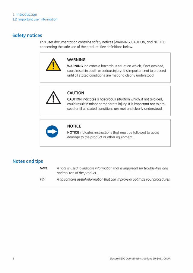
Safety noticesThis user documentation contains safety notices (WARNING, CAUTION, and NOTICE)concerning the safe use of the product. See definitions below.
WARNINGWARNING indicates a hazardous situation which, if not avoided,could result in death or serious injury. It is important not to proceeduntil all stated conditions are met and clearly understood.
CAUTIONCAUTION indicates a hazardous situation which, if not avoided,could result in minor or moderate injury. It is important not to pro-ceed until all stated conditions are met and clearly understood.
NOTICENOTICE indicates instructions that must be followed to avoiddamage to the product or other equipment.
Notes and tipsA note is used to indicate information that is important for trouble-free andoptimal use of the product.
Note:
A tip contains useful information that can improve or optimize your procedures.Tip:
8 Biacore S200 Operating Instructions 29-1431-06 AA
1 Introduction1.2 Important user information
1.3 Regulatory information
IntroductionThis section lists the directives and standards that are fulfilled by Biacore S200 system.
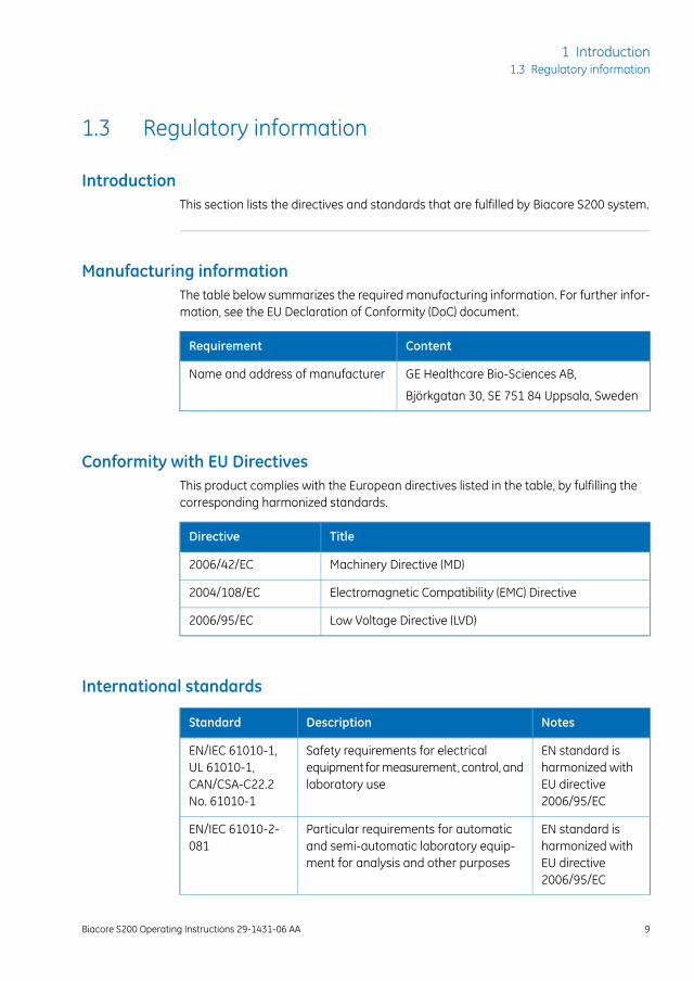
Manufacturing informationThe table below summarizes the required manufacturing information. For further infor-mation, see the EU Declaration of Conformity (DoC) document.
ContentRequirement
GE Healthcare Bio-Sciences AB,Name and address of manufacturer
Björkgatan 30, SE 751 84 Uppsala, Sweden
Conformity with EU DirectivesThis product complies with the European directives listed in the table, by fulfilling thecorresponding harmonized standards.
TitleDirective
Machinery Directive (MD)2006/42/EC
Electromagnetic Compatibility (EMC) Directive2004/108/EC
Low Voltage Directive (LVD)2006/95/EC
International standards
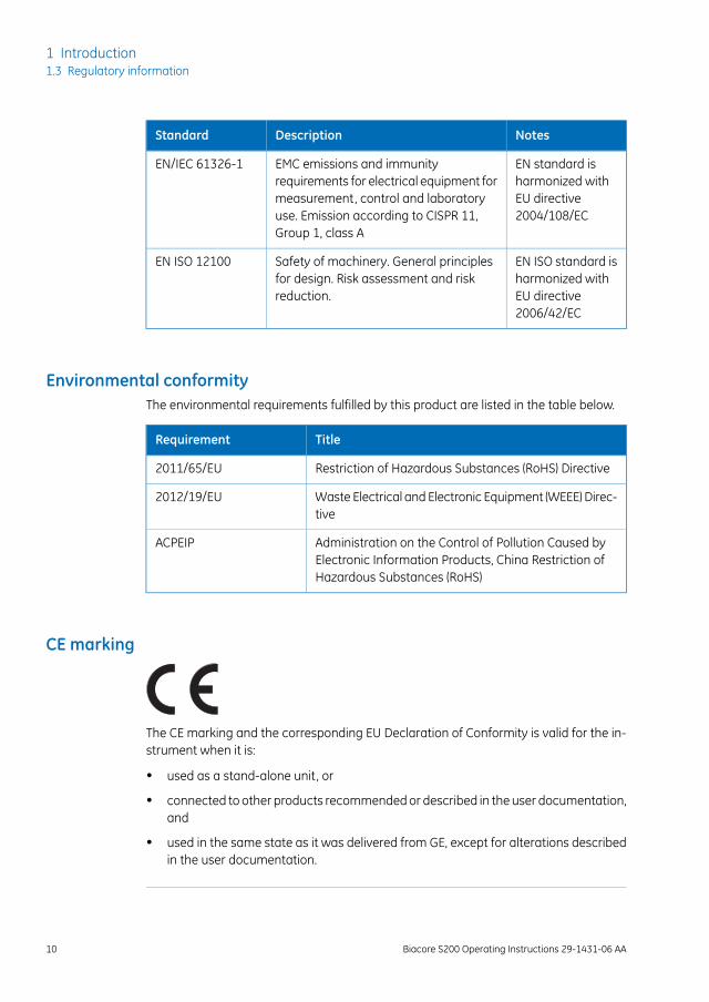
NotesDescriptionStandard
EN standard isharmonized withEU directive2006/95/EC
Safety requirements for electricalequipment for measurement, control, andlaboratory use
EN/IEC 61010-1,UL 61010-1,CAN/CSA-C22.2No. 61010-1
EN standard isharmonized withEU directive2006/95/EC
Particular requirements for automaticand semi-automatic laboratory equip-ment for analysis and other purposes
EN/IEC 61010-2-081
Biacore S200 Operating Instructions 29-1431-06 AA 9
1 Introduction1.3 Regulatory information
NotesDescriptionStandard
EN standard isharmonized withEU directive2004/108/EC
EMC emissions and immunityrequirements for electrical equipment formeasurement, control and laboratoryuse. Emission according to CISPR 11,Group 1, class A
EN/IEC 61326-1
EN ISO standard isharmonized withEU directive2006/42/EC
Safety of machinery. General principlesfor design. Risk assessment and riskreduction.
EN ISO 12100
Environmental conformityThe environmental requirements fulfilled by this product are listed in the table below.
TitleRequirement
Restriction of Hazardous Substances (RoHS) Directive2011/65/EU
Waste Electrical and Electronic Equipment (WEEE) Direc-tive
2012/19/EU
Administration on the Control of Pollution Caused byElectronic Information Products, China Restriction ofHazardous Substances (RoHS)
ACPEIP
CE marking
The CE marking and the corresponding EU Declaration of Conformity is valid for the in-strument when it is:
• used as a stand-alone unit, or
• connected to other products recommended or described in the user documentation,and
• used in the same state as it was delivered from GE, except for alterations describedin the user documentation.
10 Biacore S200 Operating Instructions 29-1431-06 AA
1 Introduction1.3 Regulatory information
Regulatory compliance ofconnected equipment
Any equipment connected to Biacore S200 should meet the safety requirements ofIEC/EN/UL/CSA 61010-1, IEC/EN/UL/CSA 60950-1, or other relevant national safety reg-ulations and standards. The equipment should be installed and used according to themanufacturer's instructions. Within EU, connected equipment must be CE marked.
Biacore S200 Operating Instructions 29-1431-06 AA 11
1 Introduction1.3 Regulatory information
1.4 Associated documentationOperation of the Control and Evaluation Software is described in the Biacore S200 Soft-ware Handbook.
Sensor surface preparation and general methodology for Biacore applications are de-scribed in theBiacore Sensor SurfaceHandbookand theBiacore AssayHandbook respec-tively.
12 Biacore S200 Operating Instructions 29-1431-06 AA
1 Introduction1.4 Associated documentation
2 Safety instructions
About this chapterThis chapter describes safety precautions and emergency shutdown procedures for theproduct. The labels on the system and information regarding recycling are also described.
Important
WARNINGBefore installing, operating ormaintaining the product, all usersmust read and understand the entire contents of this chapterto become aware of the hazards involved.
In this chapter
See pageSection
142.1 Safety precautions
202.2 Labels
222.3 Emergency procedures
242.4 Recycling information
252.5 Declaration of Hazardous Substances (DoHS)
Biacore S200 Operating Instructions 29-1431-06 AA 13
2 Safety instructions

2.1 Safety precautions
IntroductionThe safety precautions in this section are grouped in the following categories:
• General precautions
• Flammable liquids and explosive environment
• Personal protection
• Installing and moving
• Operation
• Maintenance
General precautions
WARNINGOnly properly trained personnel may perform operation and usermaintenance of the product.
WARNINGDo not operate Biacore S200 in any other way than described inthe Operating Instructions.
WARNINGDo not use any accessories not supplied or recommended by GE.
WARNINGProtective ground. The product must always be connected to agrounded power outlet.
14 Biacore S200 Operating Instructions 29-1431-06 AA
2 Safety instructions2.1 Safety precautions
WARNINGUse only mains cables supplied or approved by GE.
WARNINGDo not block the rear or side panels of the instrument. The powerswitch must always be easy to access. The power cord must alwaysbe easy to disconnect.
Flammable liquids and explosiveenvironment
WARNINGBiacore S200 is not intended for use in locations with explosion orfire hazards.
WARNINGLiquids marked as flammable must not be used as running buffer.Any buffer or reagent containing flammable substances must beplaced in properly capped vials in the sample rack.
WARNINGExplosion hazard. To avoid building up an explosive atmospherewhen using flammable liquids, make sure that the room ventilationmeets the local requirements.
Biacore S200 Operating Instructions 29-1431-06 AA 15
2 Safety instructions2.1 Safety precautions
Personal protection
WARNINGAlways wear appropriate protective clothing and equipment duringoperation and maintenance of Biacore S200 system. Use requiredsafety equipment when handling hazardous substances.
WARNINGLiquids in the buffer bottles or tubing may be toxic or flammableor may cause chemical burns or irritation to skin and eyes. Takeappropriate precautions in the event of bottle breakage, accidentalspillage and insecure fitting of tubings to bottles.
CAUTIONPinch risk! Take care that fingers are not trapped by moving partson the instrument.
CAUTIONAccidental breakage of glass bottles may leave sharp fragmentsand splinters that can cause cuts and abrasions.
Installing and moving
CAUTIONWear protective shoes with steel toecaps when moving the instru-ment to protect against falling objects.
16 Biacore S200 Operating Instructions 29-1431-06 AA
2 Safety instructions2.1 Safety precautions
CAUTIONHeavy object. Use proper lifting equipment, or use three or morepersons when moving the instrument. All lifting and moving mustbe performed in accordance with local regulations.
CAUTIONPinch risk! Make sure that hands or fingers are not trapped underthe instrument when the instrument is lifted or moved.
Operation
WARNINGHandle bottles carefully. Accidental breakage of buffer or waterbottles may cause flooding of the bottle tray, and liquid may comeinto contact with electrical circuits, causing electric shock and/orfire hazards.
WARNINGA fume hood or similar ventilation system shall be installed whenflammable or noxious substances are used.
CAUTIONAccidental breakage of buffer or water bottles may cause floodingof the bottle tray, and liquid may enter the instrument enclosure.If this happens, disconnect the instrument from the mains powerand call your local service representative.
CAUTIONDo not touch the pumps while they are moving.
Biacore S200 Operating Instructions 29-1431-06 AA 17
2 Safety instructions2.1 Safety precautions
WARNINGWaste liquids may contain hazardous or flammable substances.Take appropriate precautions to avoid spillage of hazardous wastewhich may cause infection, corrosion or fire hazard.
CAUTIONEnsure that all fluidic tubes are secured and properly connectedor sealed at both ends before, during and after operation.
CAUTIONWaste tubes and containers must be secured and sealed to preventaccidental spillage.
CAUTIONMake sure that the waste container has sufficient space for maxi-mum waste volume when the equipment is left unattended.
Maintenance
WARNINGAll service and repairs, with the exception of service operationsdescribed in the user documentation, must be carried out by per-sonnel authorized by GE. Do not open any covers or replace anyparts unless specifically stated in the user documentation.
WARNINGBiacore S200 contains mains voltage of up to 240 V AC. Disconnectmains cord before replacing fuses. Do not remove instrumentcovers.
18 Biacore S200 Operating Instructions 29-1431-06 AA
2 Safety instructions2.1 Safety precautions
WARNINGFor continued protection from fire hazard, replace only with sametype and rating of fuse.
CAUTIONAlways turn off the power before opening the sample compartment.
Decommissioning
WARNINGDecontaminate the equipment before decommissioning to ensurethat hazardous residues are removed.
Biacore S200 Operating Instructions 29-1431-06 AA 19
2 Safety instructions2.1 Safety precautions
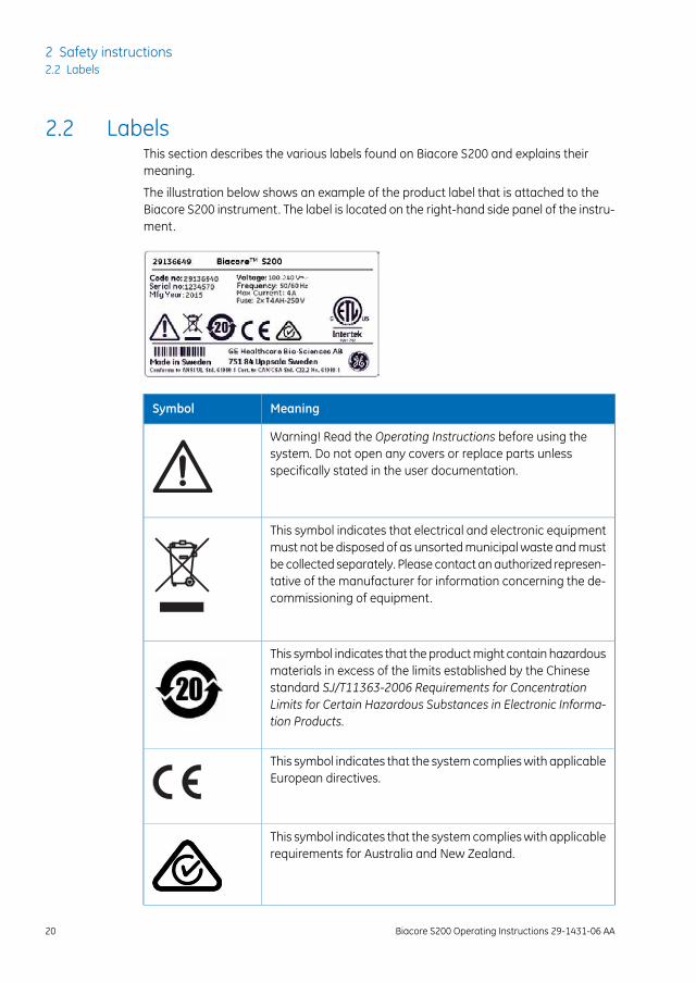
2.2 LabelsThis section describes the various labels found on Biacore S200 and explains theirmeaning.
The illustration below shows an example of the product label that is attached to theBiacore S200 instrument. The label is located on the right-hand side panel of the instru-ment.
MeaningSymbol
Warning! Read the Operating Instructions before using thesystem. Do not open any covers or replace parts unlessspecifically stated in the user documentation.
This symbol indicates that electrical and electronic equipmentmust not be disposed of as unsorted municipal waste and mustbe collected separately. Please contact an authorized represen-tative of the manufacturer for information concerning the de-commissioning of equipment.
This symbol indicates that the product might contain hazardousmaterials in excess of the limits established by the Chinesestandard SJ/T11363-2006 Requirements for ConcentrationLimits for Certain Hazardous Substances in Electronic Informa-tion Products.
This symbol indicates that the system complies with applicableEuropean directives.
This symbol indicates that the system complies with applicablerequirements for Australia and New Zealand.
20 Biacore S200 Operating Instructions 29-1431-06 AA
2 Safety instructions2.2 Labels
MeaningSymbol
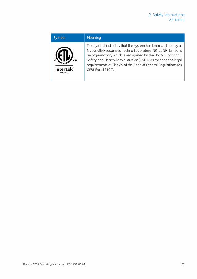
This symbol indicates that the system has been certified by aNationally Recognized Testing Laboratory (NRTL). NRTL meansan organization, which is recognized by the US OccupationalSafety and Health Administration (OSHA) as meeting the legalrequirements of Title 29 of the Code of Federal Regulations (29CFR), Part 1910.7.
Biacore S200 Operating Instructions 29-1431-06 AA 21
2 Safety instructions2.2 Labels
2.3 Emergency procedures
IntroductionThis section describes how to perform an emergency stop of Biacore S200 system.
NOTICEDo not use the emergency stop procedure unless there is a risk ofinjury, damage or loss of valuable material. All operations includingbuffer flow and data collection are stopped immediately.
To stop a run under controlled conditions before it is complete, choose Run:Stop Runfrom the menu bar in Biacore S200 Control Software. This will stop both the run and thedata collection at the end of the current cycle. A dialog is displayed while the currentcycle is finished.
In an emergency situationFollow the steps below to stop the system in an emergency.
1 PressCtrl-Break (Ctrl-Pause) on the keyboard to stop the run and the data collectionimmediately.
2 In the dialog box that appears, click Yes if you want to wash the system with runningbuffer. You should do this if possible. The wash operation takes about 3 minutes.
NOTICEDo not leave the system in an emergency stop condition. Alwaysfollow the restart procedure if possible, to restore the instrumentinto normal condition.
22 Biacore S200 Operating Instructions 29-1431-06 AA
2 Safety instructions2.3 Emergency procedures
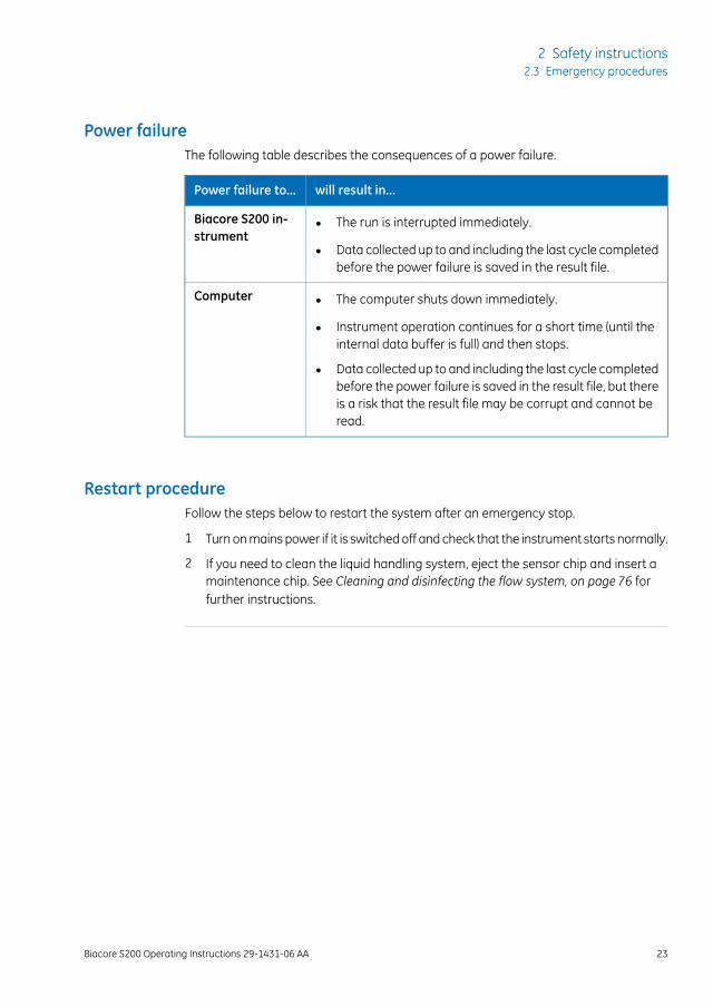
Power failureThe following table describes the consequences of a power failure.
will result in...Power failure to...
• The run is interrupted immediately.
• Data collected up to and including the last cycle completedbefore the power failure is saved in the result file.
Biacore S200 in-strument
• The computer shuts down immediately.
• Instrument operation continues for a short time (until theinternal data buffer is full) and then stops.
• Data collected up to and including the last cycle completedbefore the power failure is saved in the result file, but thereis a risk that the result file may be corrupt and cannot beread.
Computer
Restart procedureFollow the steps below to restart the system after an emergency stop.
1 Turn on mains power if it is switched off and check that the instrument starts normally.
2 If you need to clean the liquid handling system, eject the sensor chip and insert amaintenance chip. See Cleaning and disinfecting the flow system, on page 76 forfurther instructions.
Biacore S200 Operating Instructions 29-1431-06 AA 23
2 Safety instructions2.3 Emergency procedures
2.4 Recycling information
About this sectionThis section contains information about the decontamination and decommissioning ofBiacore S200.
DecontaminationThe product must be decontaminated before decommissioning. All local regulationsmust be followed with regard to scrapping of the equipment.
Disposal of the productWhen taking Biacore S200 out of service, the different materials must be separated andrecycled according to national and local environmental regulations.
Biacore S200 contains a lithium backup battery, which must not be disposed of in fire.
Disposal of electricalcomponents
Waste electrical and electronic equipment must not be disposed as unsorted municipalwaste and must be collected separately. Please contact an authorized representativeof the manufacturer for information concerning the decommissioning of the equipment.
24 Biacore S200 Operating Instructions 29-1431-06 AA
2 Safety instructions2.4 Recycling information
2.5 Declaration of Hazardous Substances (DoHS)
根据SJ/T11364-2006《电子信息产品污染控制标识要求》特提供如下有关污染 控制方面的信息。The following product pollution control information is provided according to SJ/T11364-2006 Markingfor Control of Pollution caused by Electronic Information Products.
电子信息产品污染控制标志说明Explanation of Pollution Control Label
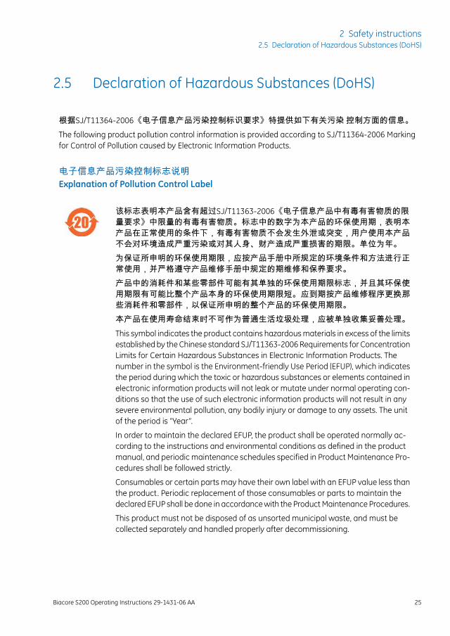
该标志表明本产品含有超过SJ/T11363-2006《电子信息产品中有毒有害物质的限量要求》中限量的有毒有害物质。标志中的数字为本产品的环保使用期,表明本产品在正常使用的条件下,有毒有害物质不会发生外泄或突变,用户使用本产品不会对环境造成严重污染或对其人身、财产造成严重损害的期限。单位为年。为保证所申明的环保使用期限,应按产品手册中所规定的环境条件和方法进行正常使用,并严格遵守产品维修手册中规定的期维修和保养要求。产品中的消耗件和某些零部件可能有其单独的环保使用期限标志,并且其环保使用期限有可能比整个产品本身的环保使用期限短。应到期按产品维修程序更换那些消耗件和零部件,以保证所申明的整个产品的环保使用期限。本产品在使用寿命结束时不可作为普通生活垃圾处理,应被单独收集妥善处理。This symbol indicates the product contains hazardous materials in excess of the limitsestablished by the Chinese standard SJ/T11363-2006 Requirements for ConcentrationLimits for Certain Hazardous Substances in Electronic Information Products. Thenumber in the symbol is the Environment-friendly Use Period (EFUP), which indicatesthe period during which the toxic or hazardous substances or elements contained inelectronic information products will not leak or mutate under normal operating con-ditions so that the use of such electronic information products will not result in anysevere environmental pollution, any bodily injury or damage to any assets. The unitof the period is “Year”.
In order to maintain the declared EFUP, the product shall be operated normally ac-cording to the instructions and environmental conditions as defined in the productmanual, and periodic maintenance schedules specified in Product Maintenance Pro-cedures shall be followed strictly.
Consumables or certain parts may have their own label with an EFUP value less thanthe product. Periodic replacement of those consumables or parts to maintain thedeclared EFUP shall be done in accordance with the Product Maintenance Procedures.
This product must not be disposed of as unsorted municipal waste, and must becollected separately and handled properly after decommissioning.
Biacore S200 Operating Instructions 29-1431-06 AA 25
2 Safety instructions2.5 Declaration of Hazardous Substances (DoHS)
有毒有害物质或元素的名称及含量Name and Concentration of Hazardous Substances
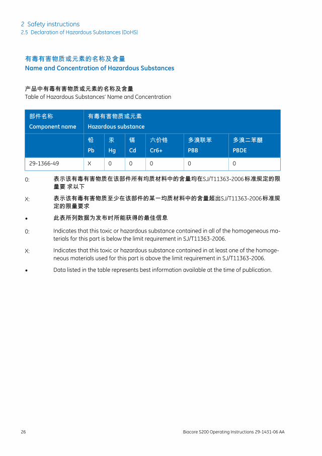
产品中有毒有害物质或元素的名称及含量Table of Hazardous Substances’ Name and Concentration
有毒有害物质或元素Hazardous substance
部件名称Component name
多溴二苯醚PBDE
多溴联苯PBB
六价铬Cr6+
镉Cd
汞Hg
铅Pb
00000X29-1366-49
0: 表示该有毒有害物质在该部件所有均质材料中的含量均在SJ/T11363-2006 标准规定的限量要 求以下
X: 表示该有毒有害物质至少在该部件的某一均质材料中的含量超出SJ/T11363-2006 标准规定的限量要求
• 此表所列数据为发布时所能获得的最佳信息
0: Indicates that this toxic or hazardous substance contained in all of the homogeneous ma-terials for this part is below the limit requirement in SJ/T11363-2006.
X: Indicates that this toxic or hazardous substance contained in at least one of the homoge-neous materials used for this part is above the limit requirement in SJ/T11363-2006.
• Data listed in the table represents best information available at the time of publication.
26 Biacore S200 Operating Instructions 29-1431-06 AA
2 Safety instructions2.5 Declaration of Hazardous Substances (DoHS)
3 System description
About this chapterThis chapter describes the essential features of Biacore S200.
In this chapter
See pageSection
283.1 Biacore S200 instrument components
353.2 Indicators and switches
373.3 Sample and reagent racks
403.4 Sensor chip and flow system
433.5 Temperature control
443.6 Control system
Biacore S200 Operating Instructions 29-1431-06 AA 27
3 System description
3.1 Biacore S200 instrument components
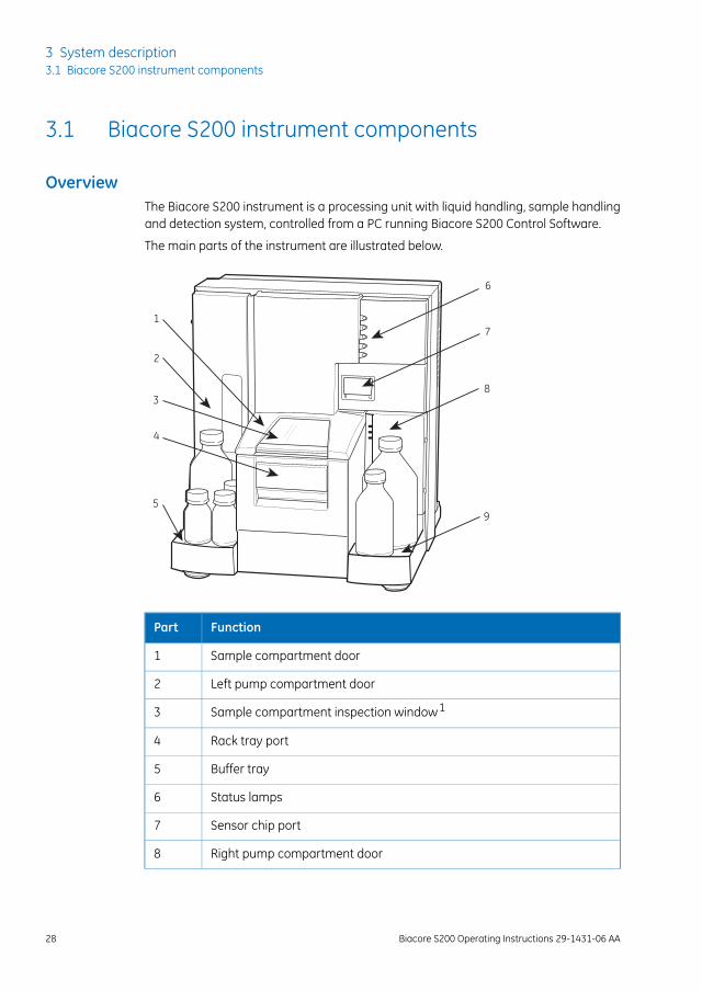
OverviewThe Biacore S200 instrument is a processing unit with liquid handling, sample handlingand detection system, controlled from a PC running Biacore S200 Control Software.
The main parts of the instrument are illustrated below.
1
4
3
2
5
6
7
8
9
FunctionPart
Sample compartment door1
Left pump compartment door2
Sample compartment inspection window13
Rack tray port4
Buffer tray5
Status lamps6
Sensor chip port7
Right pump compartment door8
28 Biacore S200 Operating Instructions 29-1431-06 AA
3 System description3.1 Biacore S200 instrument components
FunctionPart
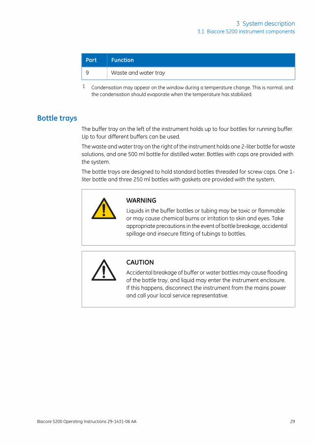
Waste and water tray9
1 Condensation may appear on the window during a temperature change. This is normal, andthe condensation should evaporate when the temperature has stabilized.
Bottle traysThe buffer tray on the left of the instrument holds up to four bottles for running buffer.Up to four different buffers can be used.
The waste and water tray on the right of the instrument holds one 2-liter bottle for wastesolutions, and one 500 ml bottle for distilled water. Bottles with caps are provided withthe system.
The bottle trays are designed to hold standard bottles threaded for screw caps. One 1-liter bottle and three 250 ml bottles with gaskets are provided with the system.
WARNINGLiquids in the buffer bottles or tubing may be toxic or flammableor may cause chemical burns or irritation to skin and eyes. Takeappropriate precautions in the event of bottle breakage, accidentalspillage and insecure fitting of tubings to bottles.
CAUTIONAccidental breakage of buffer or water bottles may cause floodingof the bottle tray, and liquid may enter the instrument enclosure.If this happens, disconnect the instrument from the mains powerand call your local service representative.
Biacore S200 Operating Instructions 29-1431-06 AA 29
3 System description3.1 Biacore S200 instrument components
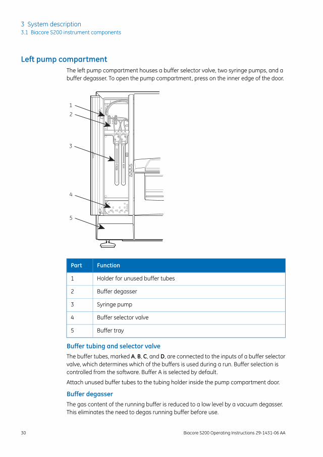
Left pump compartmentThe left pump compartment houses a buffer selector valve, two syringe pumps, and abuffer degasser. To open the pump compartment, press on the inner edge of the door.
1
2
3
4
5
FunctionPart
Holder for unused buffer tubes1
Buffer degasser2
Syringe pump3
Buffer selector valve4
Buffer tray5
Buffer tubing and selector valveThe buffer tubes, marked A, B, C, and D, are connected to the inputs of a buffer selectorvalve, which determines which of the buffers is used during a run. Buffer selection iscontrolled from the software. Buffer A is selected by default.
Attach unused buffer tubes to the tubing holder inside the pump compartment door.
Buffer degasserThe gas content of the running buffer is reduced to a low level by a vacuum degasser.This eliminates the need to degas running buffer before use.
30 Biacore S200 Operating Instructions 29-1431-06 AA
3 System description3.1 Biacore S200 instrument components
The vacuum pump of the degasser operates automatically as soon as the flow systemis started.
NOTICEThe buffer tubing should always be connected via the buffer de-gasser. Do not disconnect tubes from the degasser even if you usedegassed buffer.
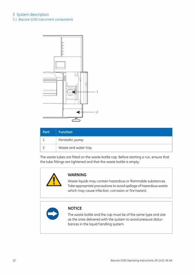
Right pump compartmentThe right pump compartment houses a peristaltic pump for supply of buffer and waterto the liquid supply block. To open the pump compartment, press on the inner edge ofthe door.
CAUTIONThe peristaltic pump may operate at any time during a run orstandby. Keep your hands clear of the pump if you open the rightpump compartment door during operation.
CAUTIONWaste tubes and containers shall be secured and sealed to preventaccidental spillage.
Biacore S200 Operating Instructions 29-1431-06 AA 31
3 System description3.1 Biacore S200 instrument components
1
2
FunctionPart
Peristaltic pump1
Waste and water tray2
The waste tubes are fitted on the waste bottle cap. Before starting a run, ensure thatthe tube fittings are tightened and that the waste bottle is empty.
WARNINGWaste liquids may contain hazardous or flammable substances.Take appropriate precautions to avoid spillage of hazardous wastewhich may cause infection, corrosion or fire hazard.
NOTICEThe waste bottle and the cap must be of the same type and sizeas the ones delivered with the system to avoid pressure distur-bances in the liquid handling system.
32 Biacore S200 Operating Instructions 29-1431-06 AA
3 System description3.1 Biacore S200 instrument components
Sample compartmentThe temperature-controlled sample compartment holds the autosampler and the sampleinjection unit. The rack tray port on the front of the instrument is controlled from thesoftware.
Illumination of the sample compartment can be switched on and off from the software.
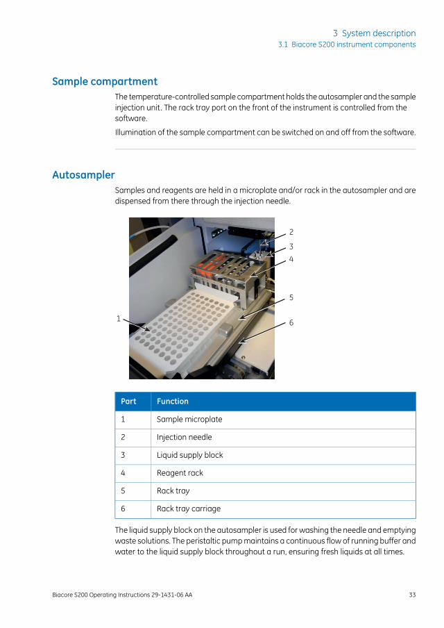
AutosamplerSamples and reagents are held in a microplate and/or rack in the autosampler and aredispensed from there through the injection needle.
1
2
3
5
4
6
FunctionPart
Sample microplate1
Injection needle2
Liquid supply block3
Reagent rack4
Rack tray5
Rack tray carriage6
The liquid supply block on the autosampler is used for washing the needle and emptyingwaste solutions. The peristaltic pump maintains a continuous flow of running buffer andwater to the liquid supply block throughout a run, ensuring fresh liquids at all times.
Biacore S200 Operating Instructions 29-1431-06 AA 33
3 System description3.1 Biacore S200 instrument components
3
21
FunctionPart
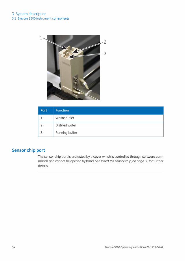
Waste outlet1
Distilled water2
Running buffer3
Sensor chip portThe sensor chip port is protected by a cover which is controlled through software com-mands and cannot be opened by hand. See Insert the sensor chip, on page56 for furtherdetails.
34 Biacore S200 Operating Instructions 29-1431-06 AA
3 System description3.1 Biacore S200 instrument components
3.2 Indicators and switches
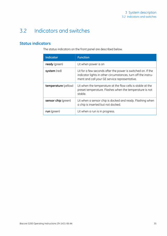
Status indicatorsThe status indicators on the front panel are described below.
FunctionIndicator
Lit when power is onready (green)
Lit for a few seconds after the power is switched on. If theindicator lights in other circumstances, turn off the instru-ment and call your GE service representative.
system (red)
Lit when the temperature at the flow cells is stable at thepreset temperature. Flashes when the temperature is notstable.
temperature (yellow)
Lit when a sensor chip is docked and ready. Flashing whena chip is inserted but not docked.
sensor chip (green)
Lit when a run is in progress.run (green)
Biacore S200 Operating Instructions 29-1431-06 AA 35
3 System description3.2 Indicators and switches
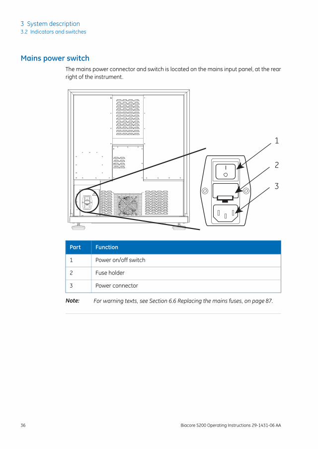
Mains power switchThe mains power connector and switch is located on the mains input panel, at the rearright of the instrument.
1
2
3
FunctionPart
Power on/off switch1
Fuse holder2
Power connector3
For warning texts, see Section 6.6 Replacing the mains fuses, on page 87.Note:
36 Biacore S200 Operating Instructions 29-1431-06 AA
3 System description3.2 Indicators and switches
3.3 Sample and reagent racks
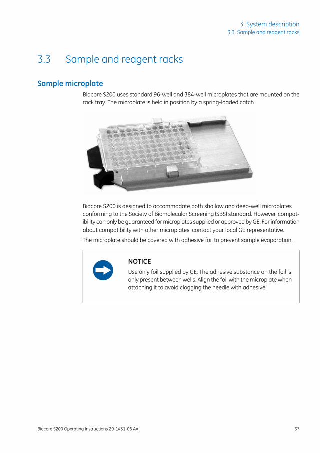
Sample microplateBiacore S200 uses standard 96-well and 384-well microplates that are mounted on therack tray. The microplate is held in position by a spring-loaded catch.
Biacore S200 is designed to accommodate both shallow and deep-well microplatesconforming to the Society of Biomolecular Screening (SBS) standard. However, compat-ibility can only be guaranteed for microplates supplied or approved by GE. For informationabout compatibility with other microplates, contact your local GE representative.
The microplate should be covered with adhesive foil to prevent sample evaporation.
NOTICEUse only foil supplied by GE. The adhesive substance on the foil isonly present between wells. Align the foil with the microplate whenattaching it to avoid clogging the needle with adhesive.
Biacore S200 Operating Instructions 29-1431-06 AA 37
3 System description3.3 Sample and reagent racks
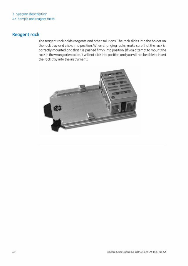
Reagent rackThe reagent rack holds reagents and other solutions. The rack slides into the holder onthe rack tray and clicks into position. When changing racks, make sure that the rack iscorrectly mounted and that it is pushed firmly into position. (If you attempt to mount therack in the wrong orientation, it will not click into position and you will not be able to insertthe rack tray into the instrument.)
38 Biacore S200 Operating Instructions 29-1431-06 AA
3 System description3.3 Sample and reagent racks
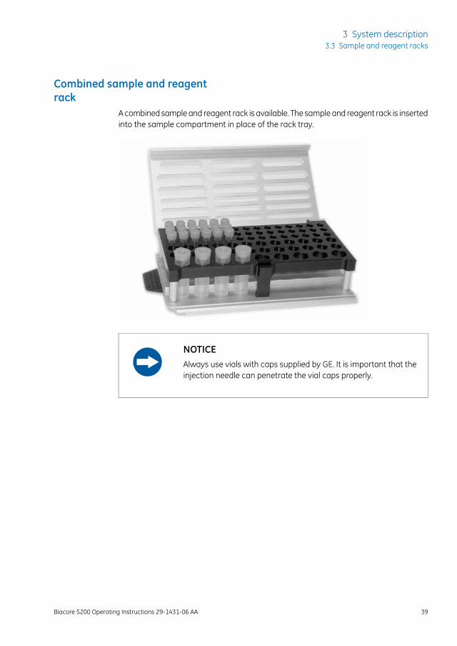
Combined sample and reagentrack
A combined sample and reagent rack is available. The sample and reagent rack is insertedinto the sample compartment in place of the rack tray.
NOTICEAlways use vials with caps supplied by GE. It is important that theinjection needle can penetrate the vial caps properly.
Biacore S200 Operating Instructions 29-1431-06 AA 39
3 System description3.3 Sample and reagent racks
3.4 Sensor chip and flow system
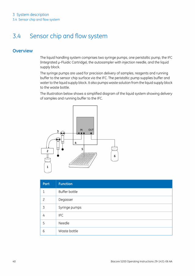
OverviewThe liquid handling system comprises two syringe pumps, one peristaltic pump, the IFC(Integrated µ-Fluidic Cartridge), the autosampler with injection needle, and the liquidsupply block.
The syringe pumps are used for precision delivery of samples, reagents and runningbuffer to the sensor chip surface via the IFC. The peristaltic pump supplies buffer andwater to the liquid supply block. It also pumps waste solution from the liquid supply blockto the waste bottle.
The illustration below shows a simplified diagram of the liquid system showing deliveryof samples and running buffer to the IFC.
1
2
3
4
5
6
FunctionPart
Buffer bottle1
Degasser2
Syringe pumps3
IFC4
Needle5
Waste bottle6
40 Biacore S200 Operating Instructions 29-1431-06 AA
3 System description3.4 Sensor chip and flow system
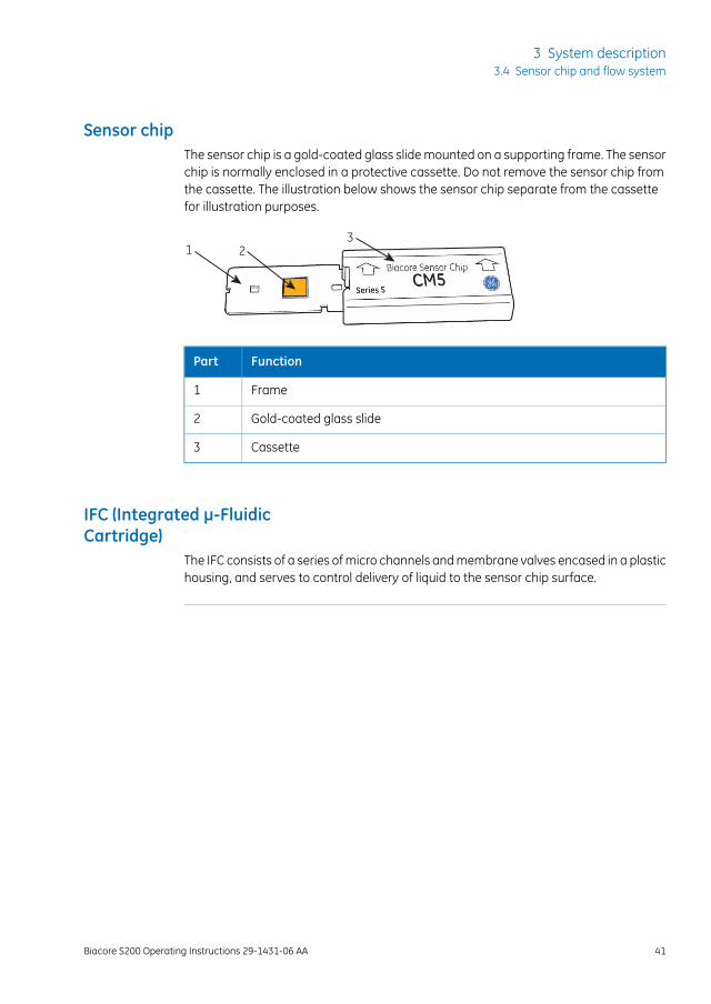
Sensor chipThe sensor chip is a gold-coated glass slide mounted on a supporting frame. The sensorchip is normally enclosed in a protective cassette. Do not remove the sensor chip fromthe cassette. The illustration below shows the sensor chip separate from the cassettefor illustration purposes.
1 23
FunctionPart
Frame1
Gold-coated glass slide2
Cassette3
IFC (Integrated µ-FluidicCartridge)
The IFC consists of a series of micro channels and membrane valves encased in a plastichousing, and serves to control delivery of liquid to the sensor chip surface.
Biacore S200 Operating Instructions 29-1431-06 AA 41
3 System description3.4 Sensor chip and flow system
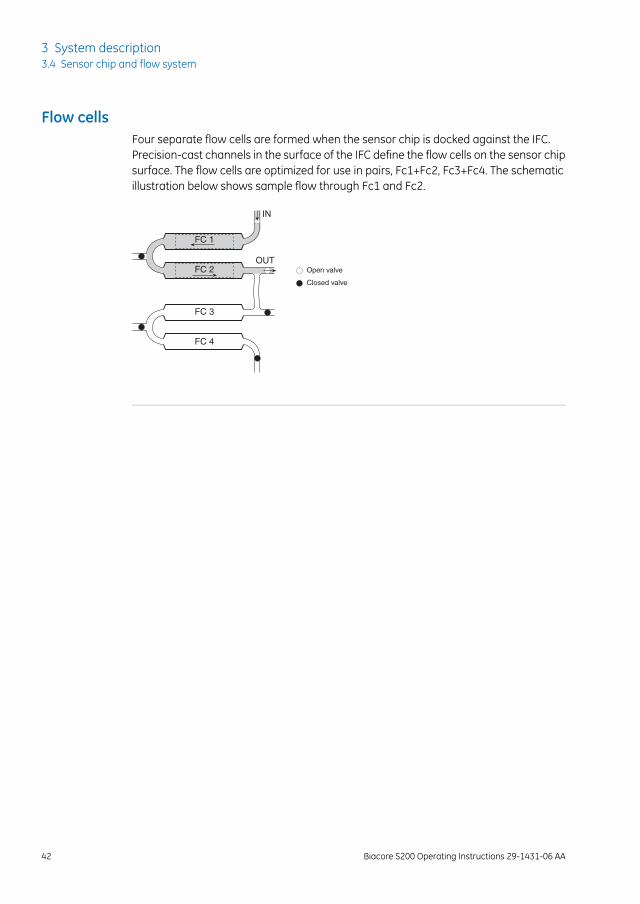
Flow cellsFour separate flow cells are formed when the sensor chip is docked against the IFC.Precision-cast channels in the surface of the IFC define the flow cells on the sensor chipsurface. The flow cells are optimized for use in pairs, Fc1+Fc2, Fc3+Fc4. The schematicillustration below shows sample flow through Fc1 and Fc2.
FC 1
FC 2
IN
OUTOpen valve
Closed valve
FC 3
FC 4
42 Biacore S200 Operating Instructions 29-1431-06 AA
3 System description3.4 Sensor chip and flow system
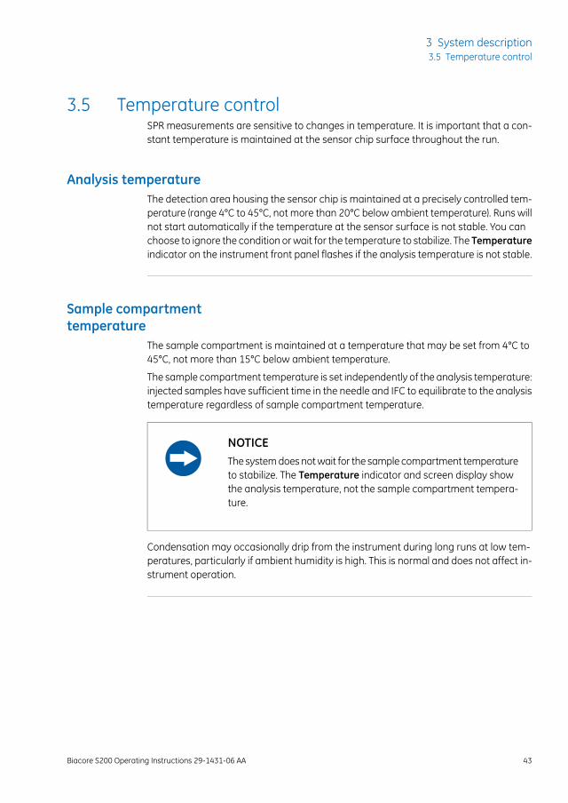
3.5 Temperature controlSPR measurements are sensitive to changes in temperature. It is important that a con-stant temperature is maintained at the sensor chip surface throughout the run.
Analysis temperatureThe detection area housing the sensor chip is maintained at a precisely controlled tem-perature (range 4°C to 45°C, not more than 20°C below ambient temperature). Runs willnot start automatically if the temperature at the sensor surface is not stable. You canchoose to ignore the condition or wait for the temperature to stabilize. The Temperatureindicator on the instrument front panel flashes if the analysis temperature is not stable.
Sample compartmenttemperature
The sample compartment is maintained at a temperature that may be set from 4°C to45°C, not more than 15°C below ambient temperature.
The sample compartment temperature is set independently of the analysis temperature:injected samples have sufficient time in the needle and IFC to equilibrate to the analysistemperature regardless of sample compartment temperature.
NOTICEThe system does not wait for the sample compartment temperatureto stabilize. The Temperature indicator and screen display showthe analysis temperature, not the sample compartment tempera-ture.
Condensation may occasionally drip from the instrument during long runs at low tem-peratures, particularly if ambient humidity is high. This is normal and does not affect in-strument operation.
Biacore S200 Operating Instructions 29-1431-06 AA 43
3 System description3.5 Temperature control
3.6 Control systemBiacore S200 Control Software is a complete software for control and supervision ofBiacore S200.
Biacore S200 Evaluation Software is a stand-alone software for evaluation of resultsobtained from Biacore S200. The software is normally installed on the same computeras the Biacore S200 Control Software, although connection to the instrument is not re-quired for using Biacore S200 Evaluation Software.
44 Biacore S200 Operating Instructions 29-1431-06 AA
3 System description3.6 Control system
4 Installation
About this chapterThis chapter provides instructions for installing and moving Biacore S200.
NOTICEBiacore S200 is prepared and installed by GE personnel. ContactGE if you require re-installation at a new site.
In this chapter
See pageSection
464.1 Site requirements
504.2 Unpacking, assembly and transport
514.3 Connections
Biacore S200 Operating Instructions 29-1431-06 AA 45
4 Installation
4.1 Site requirements
WARNINGA fume hood or similar ventilation system shall be installed whenflammable or noxious substances are used.
WARNINGExplosion hazard. To avoid building up an explosive atmospherewhen using flammable liquids, make sure that the room ventilationmeets the local requirements.
46 Biacore S200 Operating Instructions 29-1431-06 AA
4 Installation4.1 Site requirements
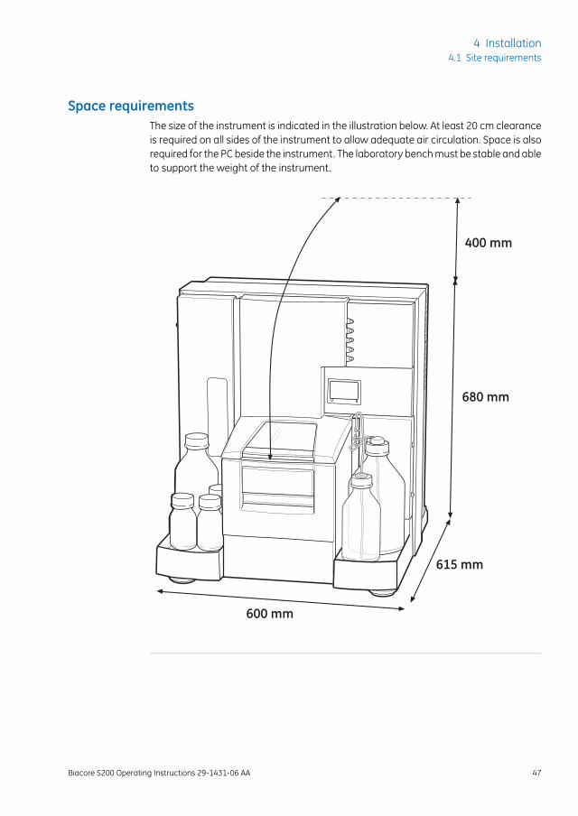
Space requirementsThe size of the instrument is indicated in the illustration below. At least 20 cm clearanceis required on all sides of the instrument to allow adequate air circulation. Space is alsorequired for the PC beside the instrument. The laboratory bench must be stable and ableto support the weight of the instrument.
400 mm
680 mm
615 mm
600 mm
Biacore S200 Operating Instructions 29-1431-06 AA 47
4 Installation4.1 Site requirements
Electrical power requirements
WARNINGProtective ground. The product must always be connected to agrounded power outlet.
WARNINGUse only mains cables supplied or approved by GE.
WARNINGDo not block the rear or side panels of the instrument. The powerswitch must always be easy to access. The power cord must alwaysbe easy to disconnect.
The instrument requires mains power outlets with protective earth as specified in thetable below.
SpecificationParameter
100 to 240 V~ ±10%, 50/60 HzSupply voltage
800 VAMaximum power (including PC andprinter)
Overvoltage category IITransient overvoltages
48 Biacore S200 Operating Instructions 29-1431-06 AA
4 Installation4.1 Site requirements
Environmental conditionsThe following general requirements must be fulfilled:
• The room must have exhaust ventilation
• The instrument should not be exposed to direct sunlight
• Dust in the atmosphere should be kept to a minimum
The installation site must comply with the following specifications:
SpecificationParameter
Indoor use onlyAllowed location
18°C to 33°CAmbient temperature, operation
80% RH, non-condensing, up to 31°C.
Decreasing linearly to 50% RH at 40°C.
Max. relative humidity, operation
-25°C to 60°CAmbient temperature, transportation/stor-age
Up to 2000 mAltitude, operation
Pollution degree 2Pollution degree of the intended environ-ment
Avoid placing the system adjacent to heaters or air conditioners.
Condensation may occur in the sample compartment at high ambient humidity. This isnormal and does not indicate any malfunction.
Biacore S200 Operating Instructions 29-1431-06 AA 49
4 Installation4.1 Site requirements
4.2 Unpacking, assembly and transport
UnpackingBiacore S200 will be unpacked by GE personnel.
Check the equipment for any apparent damage before starting installation. Documentany damage carefully and contact your GE representative.
Contact GE if you need to re-pack Biacore S200 for storage or transport.
AssemblyBiacore S200 requires no special assembly other than that performed by GE personnelduring installation.
TransportTo avoid damage, the optical unit in Biacore S200 must be secured before transportover more than limited distances within the laboratory. Contact GE for assistance.
CAUTIONWear protective shoes with steel toecaps when moving the instru-ment to protect against falling objects.
CAUTIONPinch risk! Make sure that hands or fingers are not trapped underthe instrument when the instrument is lifted or moved.
50 Biacore S200 Operating Instructions 29-1431-06 AA
4 Installation4.2 Unpacking, assembly and transport
4.3 Connections
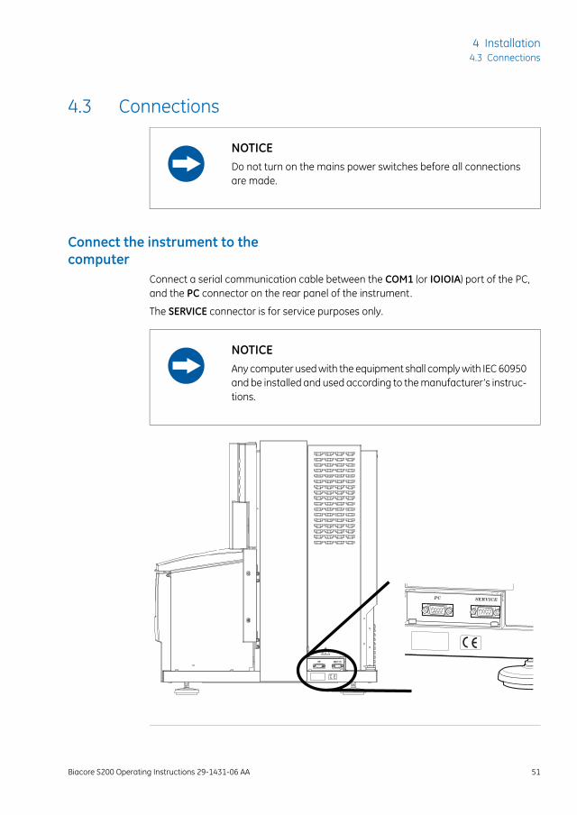
NOTICEDo not turn on the mains power switches before all connectionsare made.
Connect the instrument to thecomputer
Connect a serial communication cable between the COM1 (or IOIOIA) port of the PC,and the PC connector on the rear panel of the instrument.
The SERVICE connector is for service purposes only.
NOTICEAny computer used with the equipment shall comply with IEC 60950and be installed and used according to the manufacturer’s instruc-tions.
Biacore S200 Operating Instructions 29-1431-06 AA 51
4 Installation4.3 Connections
Connect to mains powerFollow the steps below to connect the instrument to a mains power source.
ActionStep
Connect the mains power cord delivered with the instrument, to the MAINSINLET connector on the rear panel (see Mains power switch, on page 36).Connect the other end to a mains outlet with protective earth.
1
Check that any mains voltage selectors on the PC and peripheral equipmentare set correctly.
2
Install the PC and peripheral equipment according to the respective instruc-tion manuals.
3
WARNINGDo not block the rear or side panels of the instrument. The powerswitch must always be easy to access. The power cord must alwaysbe easy to disconnect.
52 Biacore S200 Operating Instructions 29-1431-06 AA
4 Installation4.3 Connections
5 Operation
About this chapterThis chapter guides you through the basic operation of Biacore S200 system.
In this chapter
See pageSection
555.1 Starting the system
565.2 Preparing the instrument
605.3 Ejecting the rack tray
625.4 Adjusting the rack tray
635.5 Preparing samples and reagents
665.6 Changing reagent racks
675.7 Installing the rack tray
685.8 Starting and finishing a run
Safety precautions
WARNINGAlways wear appropriate protective clothing and equipment duringoperation and maintenance of Biacore S200 system. Use requiredsafety equipment when handling hazardous substances.
WARNINGDo not use any accessories not supplied or recommended by GE.
Biacore S200 Operating Instructions 29-1431-06 AA 53
5 Operation
WARNINGHandle bottles carefully. Accidental breakage of buffer or waterbottles may cause flooding of the bottle tray, and liquid may comeinto contact with electrical circuits, causing electric shock and/orfire hazards.
WARNINGLiquids in the buffer bottles or tubing may be toxic or flammableor may cause chemical burns or irritation to skin and eyes. Takeappropriate precautions in the event of bottle breakage, accidentalspillage and insecure fitting of tubings to bottles.
WARNINGWaste liquids may contain hazardous or flammable substances.Take appropriate precautions to avoid spillage of hazardous wastewhich may cause infection, corrosion or fire hazard.
CAUTIONEnsure that all fluidic tubes are secured and properly connectedor sealed at both ends before, during and after operation.
CAUTIONWaste tubes and containers shall be secured and sealed to preventaccidental spillage.
CAUTIONAccidental breakage of glass bottles may leave sharp fragmentsand splinters that can cause cuts and abrasions.
54 Biacore S200 Operating Instructions 29-1431-06 AA
5 Operation
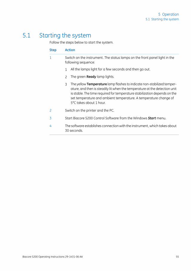
5.1 Starting the systemFollow the steps below to start the system.
ActionStep
Switch on the instrument. The status lamps on the front panel light in thefollowing sequence:
1
1 All the lamps light for a few seconds and then go out.
2 The green Ready lamp lights.
3 The yellow Temperature lamp flashes to indicate non-stabilized temper-ature, and then is steadily lit when the temperature at the detection unitis stable. The time required for temperature stabilization depends on theset temperature and ambient temperature. A temperature change of5°C takes about 1 hour.
Switch on the printer and the PC.2
Start Biacore S200 Control Software from the Windows Start menu.3
The software establishes connection with the instrument, which takes about30 seconds.
4
Biacore S200 Operating Instructions 29-1431-06 AA 55
5 Operation5.1 Starting the system
5.2 Preparing the instrument
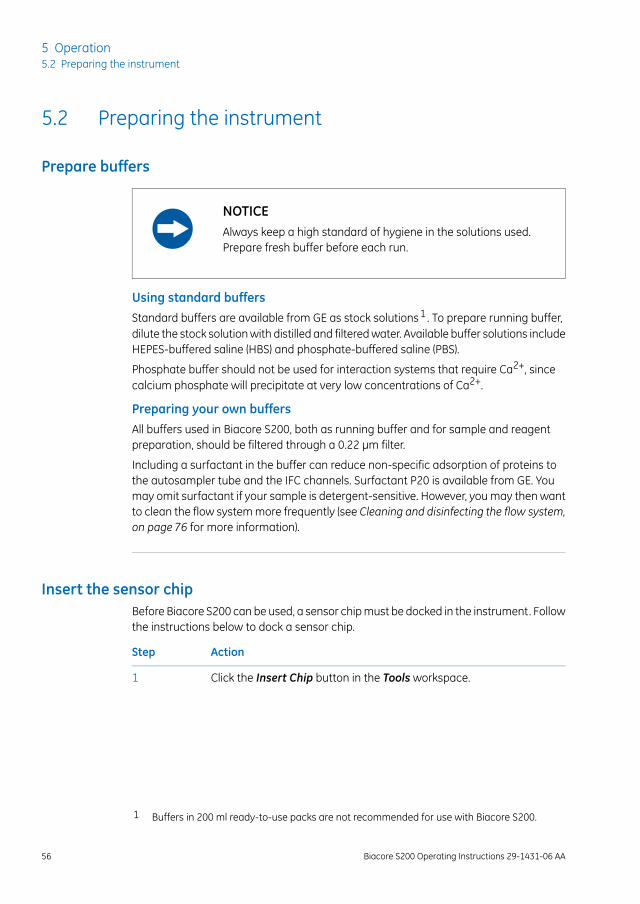
Prepare buffers
NOTICEAlways keep a high standard of hygiene in the solutions used.Prepare fresh buffer before each run.
Using standard buffersStandard buffers are available from GE as stock solutions1 . To prepare running buffer,dilute the stock solution with distilled and filtered water. Available buffer solutions includeHEPES-buffered saline (HBS) and phosphate-buffered saline (PBS).
Phosphate buffer should not be used for interaction systems that require Ca2+, sincecalcium phosphate will precipitate at very low concentrations of Ca2+.
Preparing your own buffersAll buffers used in Biacore S200, both as running buffer and for sample and reagentpreparation, should be filtered through a 0.22 µm filter.
Including a surfactant in the buffer can reduce non-specific adsorption of proteins tothe autosampler tube and the IFC channels. Surfactant P20 is available from GE. Youmay omit surfactant if your sample is detergent-sensitive. However, you may then wantto clean the flow system more frequently (see Cleaning and disinfecting the flow system,on page 76 for more information).
Insert the sensor chipBefore Biacore S200 can be used, a sensor chip must be docked in the instrument. Followthe instructions below to dock a sensor chip.
ActionStep
Click the Insert Chip button in the Tools workspace.1
1 Buffers in 200 ml ready-to-use packs are not recommended for use with Biacore S200.
56 Biacore S200 Operating Instructions 29-1431-06 AA
5 Operation5.2 Preparing the instrument
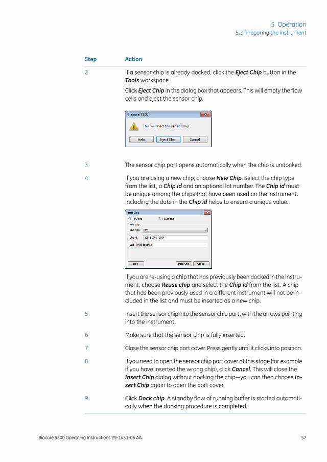
ActionStep
If a sensor chip is already docked, click the Eject Chip button in theTools workspace.
2
Click Eject Chip in the dialog box that appears. This will empty the flowcells and eject the sensor chip.
The sensor chip port opens automatically when the chip is undocked.3
If you are using a new chip, choose New Chip. Select the chip typefrom the list, a Chip id and an optional lot number. The Chip id mustbe unique among the chips that have been used on the instrument.Including the date in the Chip id helps to ensure a unique value.
4
If you are re-using a chip that has previously been docked in the instru-ment, choose Reuse chip and select the Chip id from the list. A chipthat has been previously used in a different instrument will not be in-cluded in the list and must be inserted as a new chip.
Insert the sensor chip into the sensor chip port, with the arrows pointinginto the instrument.
5
Make sure that the sensor chip is fully inserted.6
Close the sensor chip port cover. Press gently until it clicks into position.7
If you need to open the sensor chip port cover at this stage (for exampleif you have inserted the wrong chip), click Cancel. This will close theInsert Chip dialog without docking the chip—you can then choose In-sert Chip again to open the port cover.
8
Click Dock chip. A standby flow of running buffer is started automati-cally when the docking procedure is completed.
9
Biacore S200 Operating Instructions 29-1431-06 AA 57
5 Operation5.2 Preparing the instrument
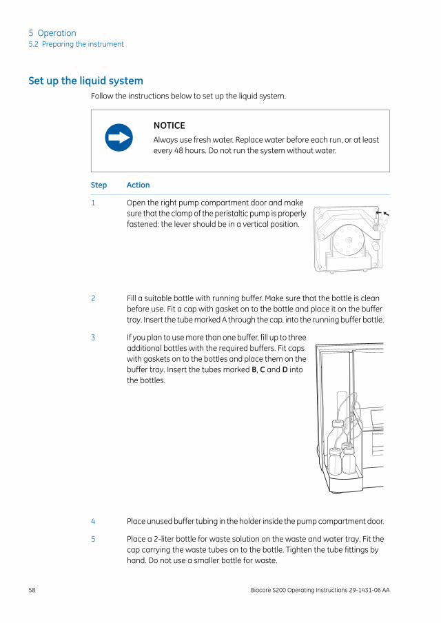
Set up the liquid systemFollow the instructions below to set up the liquid system.
NOTICEAlways use fresh water. Replace water before each run, or at leastevery 48 hours. Do not run the system without water.
ActionStep
Open the right pump compartment door and makesure that the clamp of the peristaltic pump is properlyfastened: the lever should be in a vertical position.
1
Fill a suitable bottle with running buffer. Make sure that the bottle is cleanbefore use. Fit a cap with gasket on to the bottle and place it on the buffertray. Insert the tube marked A through the cap, into the running buffer bottle.
2
If you plan to use more than one buffer, fill up to threeadditional bottles with the required buffers. Fit capswith gaskets on to the bottles and place them on thebuffer tray. Insert the tubes marked B, C and D intothe bottles.
3
Place unused buffer tubing in the holder inside the pump compartment door.4
Place a 2-liter bottle for waste solution on the waste and water tray. Fit thecap carrying the waste tubes on to the bottle. Tighten the tube fittings byhand. Do not use a smaller bottle for waste.
5
58 Biacore S200 Operating Instructions 29-1431-06 AA
5 Operation5.2 Preparing the instrument
ActionStep
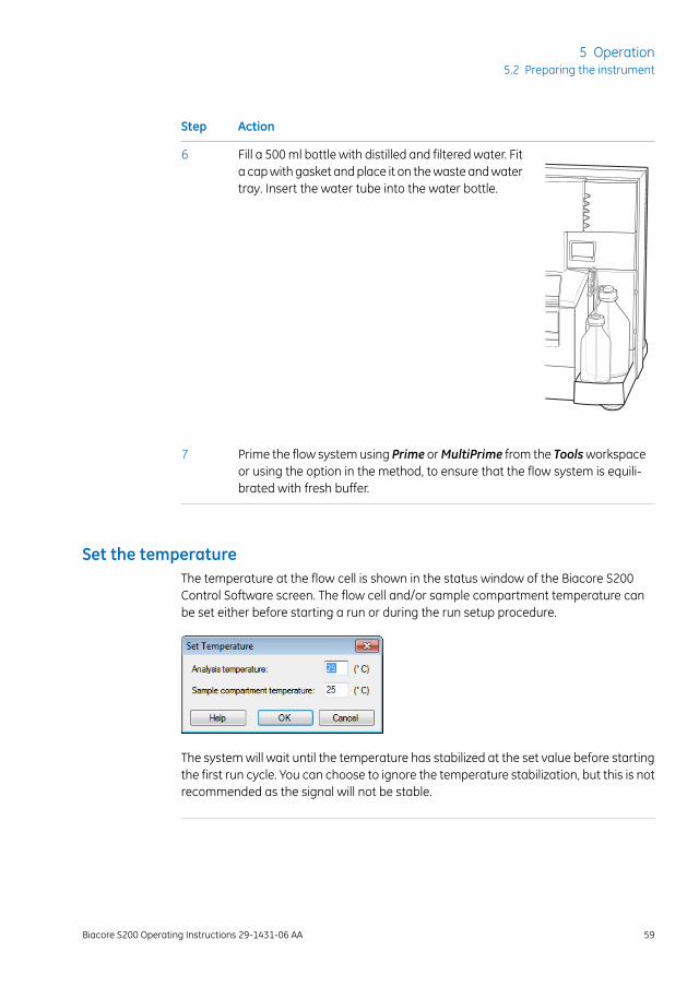
Fill a 500 ml bottle with distilled and filtered water. Fita cap with gasket and place it on the waste and watertray. Insert the water tube into the water bottle.
6
Prime the flow system using Prime orMultiPrime from the Toolsworkspaceor using the option in the method, to ensure that the flow system is equili-brated with fresh buffer.
7
Set the temperatureThe temperature at the flow cell is shown in the status window of the Biacore S200Control Software screen. The flow cell and/or sample compartment temperature canbe set either before starting a run or during the run setup procedure.
The system will wait until the temperature has stabilized at the set value before startingthe first run cycle. You can choose to ignore the temperature stabilization, but this is notrecommended as the signal will not be stable.
Biacore S200 Operating Instructions 29-1431-06 AA 59
5 Operation5.2 Preparing the instrument
5.3 Ejecting the rack tray
IntroductionThe removable rack tray carries one microplate and one reagent rack, and is mountedon the rack tray carriage in the sample compartment. The combined sample and reagentrack is mounted directly on the rack tray carriage.
The rack tray (or the sample and reagent rack) can be ejected in three situations:
• before a run, when preparing samples and reagents,
• during setup of a run,
• during a manual run.
Ejecting the rack tray before arun
ActionStep
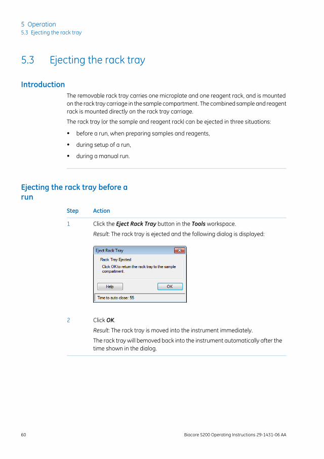
Click the Eject Rack Tray button in the Tools workspace.1
Result: The rack tray is ejected and the following dialog is displayed:
Click OK.2
Result: The rack tray is moved into the instrument immediately.
The rack tray will bemoved back into the instrument automatically after thetime shown in the dialog.
60 Biacore S200 Operating Instructions 29-1431-06 AA
5 Operation5.3 Ejecting the rack tray
CAUTIONThe rack tray automatically moves into the instrument a presettime after it has been ejected. The time is set in Tools:Preferences.A timer in the dialog indicates when the rack tray will be automat-ically moved into the instrument. Make sure no clothing or bodyparts are trapped as the rack tray moves into the instrument.
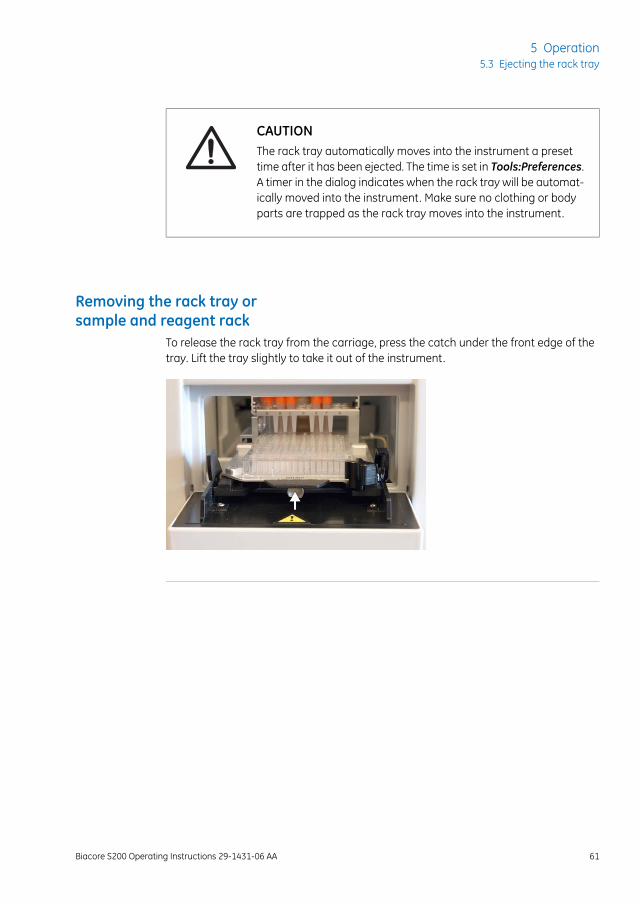
Removing the rack tray orsample and reagent rack
To release the rack tray from the carriage, press the catch under the front edge of thetray. Lift the tray slightly to take it out of the instrument.
Biacore S200 Operating Instructions 29-1431-06 AA 61
5 Operation5.3 Ejecting the rack tray
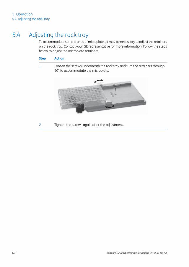
5.4 Adjusting the rack trayTo accommodate some brands of microplates, it may be necessary to adjust the retainerson the rack tray. Contact your GE representative for more information. Follow the stepsbelow to adjust the microplate retainers.
ActionStep
Loosen the screws underneath the rack tray and turn the retainers through90° to accommodate the microplate.
1
Tighten the screws again after the adjustment.2
62 Biacore S200 Operating Instructions 29-1431-06 AA
5 Operation5.4 Adjusting the rack tray
5.5 Preparing samples and reagents
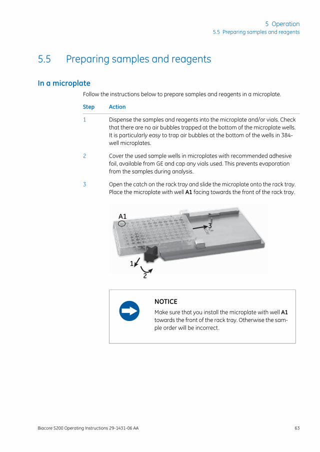
In a microplateFollow the instructions below to prepare samples and reagents in a microplate.
ActionStep
Dispense the samples and reagents into the microplate and/or vials. Checkthat there are no air bubbles trapped at the bottom of the microplate wells.It is particularly easy to trap air bubbles at the bottom of the wells in 384-well microplates.
1
Cover the used sample wells in microplates with recommended adhesivefoil, available from GE and cap any vials used. This prevents evaporationfrom the samples during analysis.
2
Open the catch on the rack tray and slide the microplate onto the rack tray.Place the microplate with well A1 facing towards the front of the rack tray.
3
1
2
3A1
NOTICEMake sure that you install the microplate with well A1towards the front of the rack tray. Otherwise the sam-ple order will be incorrect.
Biacore S200 Operating Instructions 29-1431-06 AA 63
5 Operation5.5 Preparing samples and reagents
ActionStep
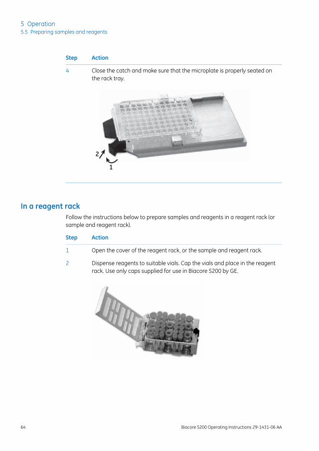
Close the catch and make sure that the microplate is properly seated onthe rack tray.
4
1
2
In a reagent rackFollow the instructions below to prepare samples and reagents in a reagent rack (orsample and reagent rack).
ActionStep
Open the cover of the reagent rack, or the sample and reagent rack.1
Dispense reagents to suitable vials. Cap the vials and place in the reagentrack. Use only caps supplied for use in Biacore S200 by GE.
2
64 Biacore S200 Operating Instructions 29-1431-06 AA
5 Operation5.5 Preparing samples and reagents
ActionStep
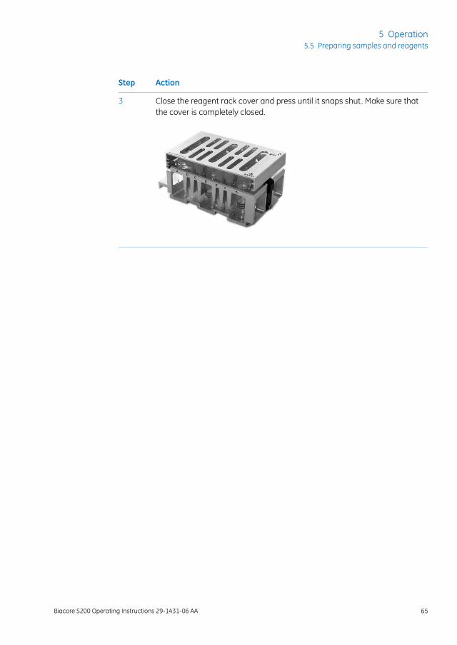
Close the reagent rack cover and press until it snaps shut. Make sure thatthe cover is completely closed.
3
Biacore S200 Operating Instructions 29-1431-06 AA 65
5 Operation5.5 Preparing samples and reagents

5.6 Changing reagent racksFollow the instructions below to change the reagent rack on the rack tray.
ActionStep
Remove the rack from the rack tray by pushing firmly on the rack towardsthe back of the tray.
1
Slide the new rack into the holder on the rack tray from the back of the tray.Make sure that it is correctly oriented. The rack can only be fully inserted inone orientation.
2
Push the rack until it snaps into position on the rack tray. Make sure that therack is properly in place.
Note:
If the rack is not correctly mounted, youwill not be able to insert the rack trayinto the instrument.
3
66 Biacore S200 Operating Instructions 29-1431-06 AA
5 Operation5.6 Changing reagent racks
5.7 Installing the rack trayFollow the instructions below to install the rack tray or sample and reagent rack.
ActionStep
If the rack tray port is not open when you are ready to install the rack tray,eject the rack tray carriage.
1
Insert the rack tray. Press gently until the rack tray snaps into place.2
The rack tray carriage automatically moves into the instrument a presettime after it has been ejected. The time is set in Tools:Preferences. Click OKin the Eject Rack Tray dialog to move the rack tray into the instrument im-mediately.
3
CAUTIONThe rack tray automatically moves into the instrumenta preset time after it has been ejected. The time is setin Tools:Preferences. A timer in the dialog indicateswhen the rack tray will be automatically moved intothe instrument. Make sure no clothing or body partsare trapped as the rack tray moves into the instrument.
The rack tray cannot be accessed during an automated run.Note:
Biacore S200 Operating Instructions 29-1431-06 AA 67
5 Operation5.7 Installing the rack tray
5.8 Starting and finishing a run
Start a runWhen docking of the sensor chip is ready, a standby flow of running buffer is started.
For details of how to start a run, refer to the Biacore S200 Software Handbook.
Standby modeWhen a run is completed, the instrument is automatically placed in standby mode. Acontinuous low flow of buffer (using buffer tubeA) is maintained through the flow systemto prevent accumulation of buffer residues.
The default standby period is 7 days. Liquid consumption during standby is approximately65 ml per 24 hours.
NOTICEAs a general recommendation use distilled and filtered water forstandby to minimize salt deposits. However, if an immobilizedsensor chip is docked and will be used for analysis later, buffer maybe used to protect the ligand on the sensor surface.
Wash buffer tubingUse the maintenance toolWashBuffer Tubingwhen you change from buffers containingsubstances that tend to adsorb to the tubing, e.g. detergent or serum albumin.
If you have used buffer tubes B, C or D and do not plan to use them in coming runs, runthe maintenance tool Empty Buffer Tubing to wash and empty the buffer tubing, thenplace unused tubes in the holder in the left pump compartment.
ShutdownIf you want to shut down the instrument completely, see Section 6.5 Shutting down thesystem, on page 85 for instructions.
68 Biacore S200 Operating Instructions 29-1431-06 AA
5 Operation5.8 Starting and finishing a run
6 Maintenance
About this chapterThis chapter summarizes user maintenance procedures. If more extensive service is re-quired, please contact your GE service representative. Complete the appropriate Healthand Safety Declaration Form before contacting your local service representative or re-turning the system for maintenance or service.
Several maintenance operations are performed using software tools with on-screen in-structions in English. SeeAppendix A Software tool texts, on page100 for these instructionsin your local language.
WARNINGAll service and repairs, with the exception of service operationsdescribed in the user documentation, must be carried out by per-sonnel authorized by GE. Do not open any covers or replace anyparts unless specifically stated in the user documentation.
WARNINGAlways wear appropriate protective clothing and equipment duringoperation and maintenance of Biacore S200 system. Use requiredsafety equipment when handling hazardous substances.
CAUTIONPinch risk! Take care that fingers are not trapped by moving partson the instrument.
In this chapter
See pageSection
716.1 Introduction
726.2 Maintenance summary
Biacore S200 Operating Instructions 29-1431-06 AA 69
6 Maintenance
See pageSection
756.3 User maintenance operations
796.4 User service operations
856.5 Shutting down the system
876.6 Replacing the mains fuses
70 Biacore S200 Operating Instructions 29-1431-06 AA
6 Maintenance
6.1 IntroductionMake sure that the BIAmaintenance Kit type 2 is available before starting maintenanceprocedures.
Regular maintenance of Biacore S200 is essential for reliable results. It is important tokeep the instrument free from contamination such as microbial growth and adsorbedproteins in the liquid handling system.
Regular checks and maintenance should be done according to the schedules below.You will be reminded of the need for Desorb and Desorb and Sanitize procedures via amaintenance scheduler in the Control Software. Do not ignore maintenance reminders.
Safety precautions
WARNINGIf the instrument may be contaminated with biohazards, decontam-inate the instrument before performing maintenance on any instru-ment parts. Contact your local service representative for furtherinformation about decontamination procedures.
WARNINGBIAdisinfectant solution is corrosive. The solution should be dilutedshortly before use as described in the Instructions for Use providedwith the Maintenance Kit.
NOTICESome maintenance procedures will destroy the ligand on a pre-pared sensor chip. Always use the separate Sensor Chip Mainte-nance that is included in the Maintenance Kit unless otherwisestated.
NOTICEDo not use BIAdesorb solution 1 at analysis temperatures below20°C. BIAdesorb solution 1 precipitates at low temperatures.
Biacore S200 Operating Instructions 29-1431-06 AA 71
6 Maintenance6.1 Introduction
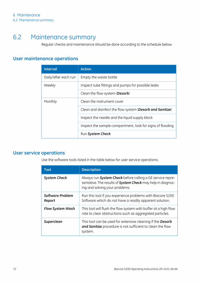
6.2 Maintenance summaryRegular checks and maintenance should be done according to the schedule below.
User maintenance operations
ActionInterval
Empty the waste bottleDaily/after each run
Inspect tube fittings and pumps for possible leaksWeekly
Clean the flow system (Desorb)
Clean the instrument coverMonthly
Clean and disinfect the flow system (Desorb and Sanitize)
Inspect the needle and the liquid supply block
Inspect the sample compartment, look for signs of flooding
Run System Check
User service operationsUse the software tools listed in the table below for user service operations.
DescriptionTool
Always run System Check before calling a GE service repre-sentative. The results of SystemCheckmay help in diagnos-ing and solving your problems.
System Check
Run this tool if you experience problems with Biacore S200Software which do not have a readily apparent solution.
Software ProblemReport
This tool will flush the flow system with buffer at a high flowrate to clear obstructions such as aggregated particles.
Flow SystemWash
This tool can be used for extensive cleaning if the Desorband Sanitize procedure is not sufficient to clean the flowsystem.
Superclean
72 Biacore S200 Operating Instructions 29-1431-06 AA
6 Maintenance6.2 Maintenance summary
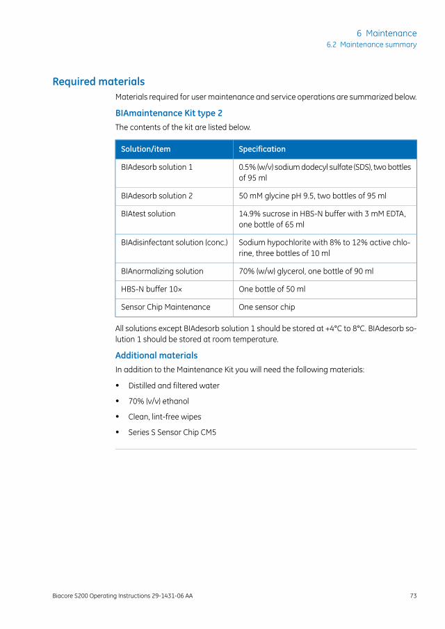
Required materialsMaterials required for user maintenance and service operations are summarized below.
BIAmaintenance Kit type 2The contents of the kit are listed below.
SpecificationSolution/item
0.5% (w/v) sodium dodecyl sulfate (SDS), two bottlesof 95 ml
BIAdesorb solution 1
50 mM glycine pH 9.5, two bottles of 95 mlBIAdesorb solution 2
14.9% sucrose in HBS-N buffer with 3 mM EDTA,one bottle of 65 ml
BIAtest solution
Sodium hypochlorite with 8% to 12% active chlo-rine, three bottles of 10 ml
BIAdisinfectant solution (conc.)
70% (w/w) glycerol, one bottle of 90 mlBIAnormalizing solution
One bottle of 50 mlHBS-N buffer 10×
One sensor chipSensor Chip Maintenance
All solutions except BIAdesorb solution 1 should be stored at +4°C to 8°C. BIAdesorb so-lution 1 should be stored at room temperature.
Additional materialsIn addition to the Maintenance Kit you will need the following materials:
• Distilled and filtered water
• 70% (v/v) ethanol
• Clean, lint-free wipes
• Series S Sensor Chip CM5
Biacore S200 Operating Instructions 29-1431-06 AA 73
6 Maintenance6.2 Maintenance summary
Preventive maintenanceTo ensure correct performance of Biacore S200, preventive maintenance should be doneregularly by a qualified GE service representative. During the maintenance visit, wornparts are replaced and all vital modules of the system are tested.
The following components are always replaced:
• IFC
• Opto-interface
• Syringe pumps
• Peristaltic pump tubing
74 Biacore S200 Operating Instructions 29-1431-06 AA
6 Maintenance6.2 Maintenance summary
6.3 User maintenance operations
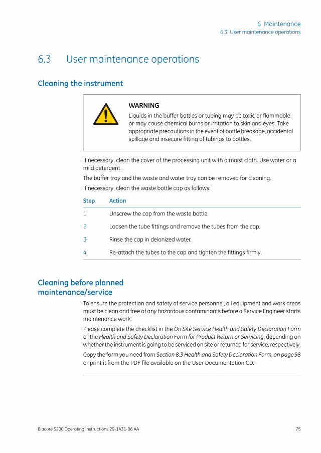
Cleaning the instrument
WARNINGLiquids in the buffer bottles or tubing may be toxic or flammableor may cause chemical burns or irritation to skin and eyes. Takeappropriate precautions in the event of bottle breakage, accidentalspillage and insecure fitting of tubings to bottles.
If necessary, clean the cover of the processing unit with a moist cloth. Use water or amild detergent.
The buffer tray and the waste and water tray can be removed for cleaning.
If necessary, clean the waste bottle cap as follows:
ActionStep
Unscrew the cap from the waste bottle.1
Loosen the tube fittings and remove the tubes from the cap.2
Rinse the cap in deionized water.3
Re-attach the tubes to the cap and tighten the fittings firmly.4
Cleaning before plannedmaintenance/service
To ensure the protection and safety of service personnel, all equipment and work areasmust be clean and free of any hazardous contaminants before a Service Engineer startsmaintenance work.
Please complete the checklist in the On Site Service Health and Safety Declaration Formor the Health and Safety Declaration Form for Product Return or Servicing, depending onwhether the instrument is going to be serviced on site or returned for service, respectively.
Copy the form you need from Section 8.3 Health and Safety Declaration Form, on page98or print it from the PDF file available on the User Documentation CD.
Biacore S200 Operating Instructions 29-1431-06 AA 75
6 Maintenance6.3 User maintenance operations
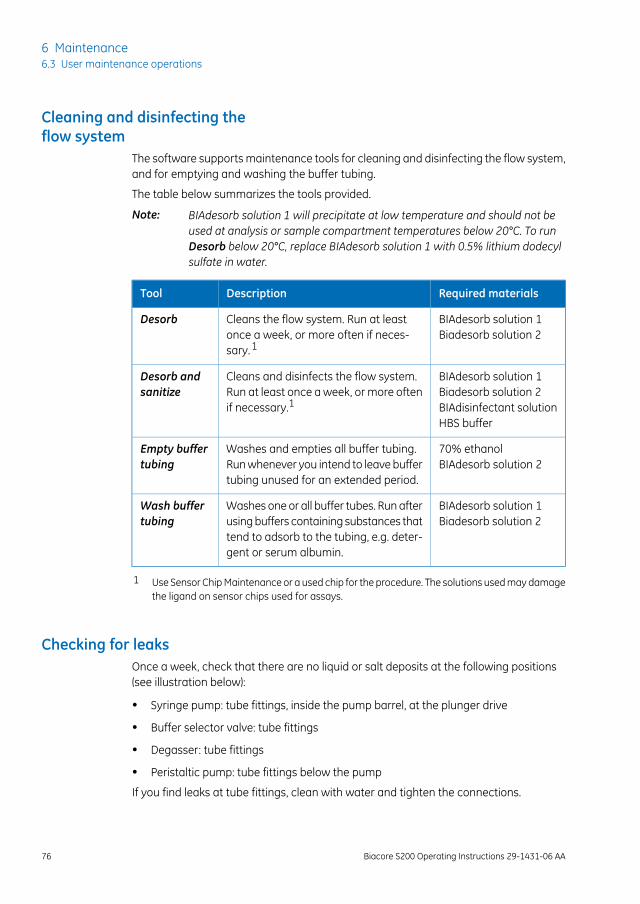
Cleaning and disinfecting theflow system
The software supports maintenance tools for cleaning and disinfecting the flow system,and for emptying and washing the buffer tubing.
The table below summarizes the tools provided.
BIAdesorb solution 1 will precipitate at low temperature and should not beused at analysis or sample compartment temperatures below 20°C. To runDesorb below 20°C, replace BIAdesorb solution 1 with 0.5% lithium dodecylsulfate in water.
Note:
Required materialsDescriptionTool
BIAdesorb solution 1Biadesorb solution 2
Cleans the flow system. Run at leastonce a week, or more often if neces-sary. 1
Desorb
BIAdesorb solution 1Biadesorb solution 2BIAdisinfectant solutionHBS buffer
Cleans and disinfects the flow system.Run at least once a week, or more oftenif necessary.1
Desorb andsanitize
70% ethanolBIAdesorb solution 2
Washes and empties all buffer tubing.Run whenever you intend to leave buffertubing unused for an extended period.
Empty buffertubing
BIAdesorb solution 1Biadesorb solution 2
Washes one or all buffer tubes. Run afterusing buffers containing substances thattend to adsorb to the tubing, e.g. deter-gent or serum albumin.
Wash buffertubing
1 Use Sensor Chip Maintenance or a used chip for the procedure. The solutions used may damagethe ligand on sensor chips used for assays.
Checking for leaksOnce a week, check that there are no liquid or salt deposits at the following positions(see illustration below):
• Syringe pump: tube fittings, inside the pump barrel, at the plunger drive
• Buffer selector valve: tube fittings
• Degasser: tube fittings
• Peristaltic pump: tube fittings below the pump
If you find leaks at tube fittings, clean with water and tighten the connections.
76 Biacore S200 Operating Instructions 29-1431-06 AA
6 Maintenance6.3 User maintenance operations
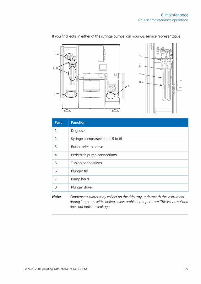
If you find leaks in either of the syringe pumps, call your GE service representative.
1
2
3
4
5
6
7
8
FunctionPart
Degasser1
Syringe pumps (see items 5 to 8)2
Buffer selector valve3
Peristaltic pump connections4
Tubing connections5
Plunger tip6
Pump barrel7
Plunger drive8
Condensate water may collect on the drip tray underneath the instrumentduring long runs with cooling below ambient temperature. This is normal anddoes not indicate leakage.
Note:
Biacore S200 Operating Instructions 29-1431-06 AA 77
6 Maintenance6.3 User maintenance operations
Normalizing the detectorThis procedure adjusts the detector response to compensate for slight differences inindividual sensor chips. For best performance, run this procedure once for each newchip. The procedure can either be run before immobilization or before the first run usingthe immobilized chip. Normalization injects BIAnormalizing solution (70% glycerol inwater) over the chip surface.
The detector can be normalized either by using the maintenance tool Normalize beforestarting a run or during the run setup procedure.
Required solutions
BIAnormalizing solution
NOTICERun Normalize with the sensor chip that will be used for the run.Do not use Sensor Chip Maintenance for this purpose.
78 Biacore S200 Operating Instructions 29-1431-06 AA
6 Maintenance6.3 User maintenance operations
6.4 User service operationsThe software supports test and service tools for SystemCheck, Software ProblemReport,Flow SystemWash, and Superclean.
System CheckThis procedure performs a comprehensive check of system performance, using a standardsucrose solution (BIAtest solution), provided in the Biacore Maintenance Kit.
Use a new Sensor Chip CM5 for this procedure.
Required solutions
BIAtest solution
HBS-N buffer
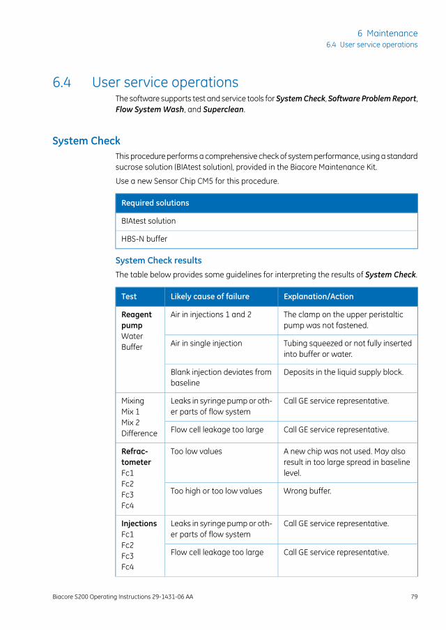
System Check resultsThe table below provides some guidelines for interpreting the results of System Check.
Explanation/ActionLikely cause of failureTest
The clamp on the upper peristalticpump was not fastened.
Air in injections 1 and 2ReagentpumpWaterBuffer Tubing squeezed or not fully inserted
into buffer or water.Air in single injection
Deposits in the liquid supply block.Blank injection deviates frombaseline
Call GE service representative.Leaks in syringe pump or oth-er parts of flow system
MixingMix 1Mix 2Difference Call GE service representative.Flow cell leakage too large
A new chip was not used. May alsoresult in too large spread in baselinelevel.
Too low valuesRefrac-tometerFc1Fc2Fc3Fc4
Wrong buffer.Too high or too low values
Call GE service representative.Leaks in syringe pump or oth-er parts of flow system
InjectionsFc1Fc2Fc3Fc4
Call GE service representative.Flow cell leakage too large
Biacore S200 Operating Instructions 29-1431-06 AA 79
6 Maintenance6.4 User service operations
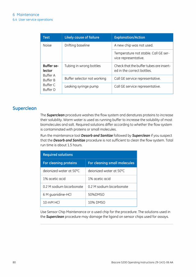
Explanation/ActionLikely cause of failureTest
A new chip was not used.Drifting baselineNoise
Temperature not stable. Call GE ser-vice representative.
Check that the buffer tubes are insert-ed in the correct bottles.
Tubing in wrong bottlesBuffer se-lectorBuffer ABuffer BBuffer CBuffer D
Call GE service representative.Buffer selector not working
Call GE service representative.Leaking syringe pump
SupercleanThe Superclean procedure washes the flow system and denatures proteins to increasetheir solubility. Warm water is used as running buffer to increase the solubility of mostbiomolecules and salt. Required solutions differ according to whether the flow systemis contaminated with proteins or small molecules.
Run the maintenance tool Desorb and Sanitize followed by Superclean if you suspectthat the Desorb and Sanitize procedure is not sufficient to clean the flow system. Totalrun time is about 1.5 hours.
Required solutions
For cleaning small moleculesFor cleaning proteins
deionized water at 50°Cdeionized water at 50°C
1% acetic acid1% acetic acid
0.2 M sodium bicarbonate0.2 M sodium bicarbonate
50%DMSO6 M guanidine-HCl
10% DMSO10 mM HCl
Use Sensor Chip Maintenance or a used chip for the procedure. The solutions used inthe Superclean procedure may damage the ligand on sensor chips used for assays.
80 Biacore S200 Operating Instructions 29-1431-06 AA
6 Maintenance6.4 User service operations
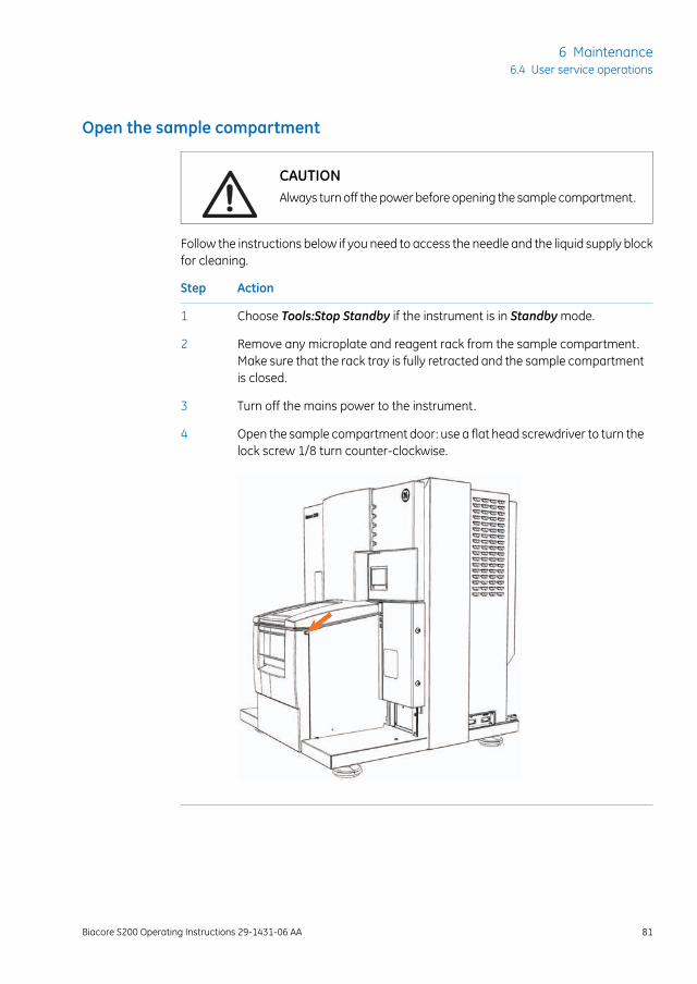
Open the sample compartment
CAUTIONAlways turn off the power before opening the sample compartment.
Follow the instructions below if you need to access the needle and the liquid supply blockfor cleaning.
ActionStep
Choose Tools:Stop Standby if the instrument is in Standby mode.1
Remove any microplate and reagent rack from the sample compartment.Make sure that the rack tray is fully retracted and the sample compartmentis closed.
2
Turn off the mains power to the instrument.3
Open the sample compartment door: use a flat head screwdriver to turn thelock screw 1/8 turn counter-clockwise.
4
Biacore S200 Operating Instructions 29-1431-06 AA 81
6 Maintenance6.4 User service operations
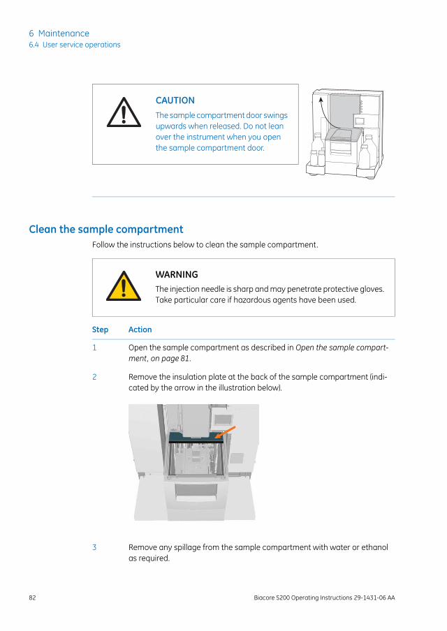
CAUTIONThe sample compartment door swingsupwards when released. Do not leanover the instrument when you openthe sample compartment door.
Clean the sample compartmentFollow the instructions below to clean the sample compartment.
WARNINGThe injection needle is sharp and may penetrate protective gloves.Take particular care if hazardous agents have been used.
ActionStep
Open the sample compartment as described in Open the sample compart-ment, on page 81.
1
Remove the insulation plate at the back of the sample compartment (indi-cated by the arrow in the illustration below).
2
Remove any spillage from the sample compartment with water or ethanolas required.
3
82 Biacore S200 Operating Instructions 29-1431-06 AA
6 Maintenance6.4 User service operations
ActionStep
Dry with a lint-free cloth.4
If salt residues have accumulated on the needle or liquid supply block, re-move them with a damp cloth.
5
Replace the insulation plate at the back of the sample compartment.6
Pull down the sample compartment door, and close the door by pressing itdown until it snaps into position.
7
Start the instrument and the software.8
Run Prime to wash the needle and the liquid supply block.9
Remove the samplecompartment box
If required, the sample compartment box can be removed for better access to thesample compartment.
Follow the instructions below to remove the sample compartment box.
ActionStep
Open the sample compartment.1
Pull out the tubing from the water bottle and remove the bottle.2
Remove the cap from the waste bottle and remove the bottle.3
Pull out the tubing from the buffer bottles and remove the bottles. Place thetubing ends in the holder inside the left pump compartment.
4
Remove the buffer tray and the waste and water tray.5
Biacore S200 Operating Instructions 29-1431-06 AA 83
6 Maintenance6.4 User service operations
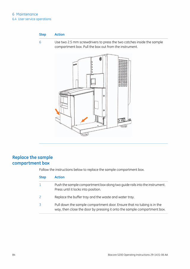
ActionStep
Use two 2.5 mm screwdrivers to press the two catches inside the samplecompartment box. Pull the box out from the instrument.
6
Replace the samplecompartment box
Follow the instructions below to replace the sample compartment box.
ActionStep
Push the sample compartment box along two guide rails into the instrument.Press until it locks into position.
1
Replace the buffer tray and the waste and water tray.2
Pull down the sample compartment door. Ensure that no tubing is in theway, then close the door by pressing it onto the sample compartment box.
3
84 Biacore S200 Operating Instructions 29-1431-06 AA
6 Maintenance6.4 User service operations
6.5 Shutting down the systemBiacore S200 should normally be left in standby mode when not in use. The instrumentmaintains a low flow of liquid through the flow system. The maximum unattendedstandby period is 7 days.
If the instrument is not to be used for a period of about two weeks or more, run theShutdown procedure to shut the instrument down completely.
StandbyThe instrument enters standby mode automatically at the end of a run. To put the instru-ment in standby mode manually, choose Tools:Standby.
NOTICEAs a general recommendation use distilled and filtered water forstandby to minimize salt deposits. However, if an immobilizedsensor chip is docked and will be used for analysis later, buffer maybe used to protect the ligand on the sensor surface.
Before leaving the instrument unattended in standby mode:
• Check that there is sufficient water or buffer for the standby period, and that thebuffer tube markedA is fully inserted into the water bottle. Liquid consumption duringstandby is approximately 65 ml/24 h.
• Check that the waste bottle is emptied.
ShutdownFollow the instructions below to shut down the instrument completely.
ActionStep
Run Desorb and Sanitize to clean the flow system.1
Eject the rack tray carriage and remove the rack tray.2
Prepare a bottle of distilled and filtered water, and a bottle of 70% ethanol.Choose Shutdown from the Tools menu. Follow the instructions on thescreen.
3
The procedure flushes the flow system and then empties the IFC of liquid.Total run time is about 20 minutes.
Biacore S200 Operating Instructions 29-1431-06 AA 85
6 Maintenance6.5 Shutting down the system
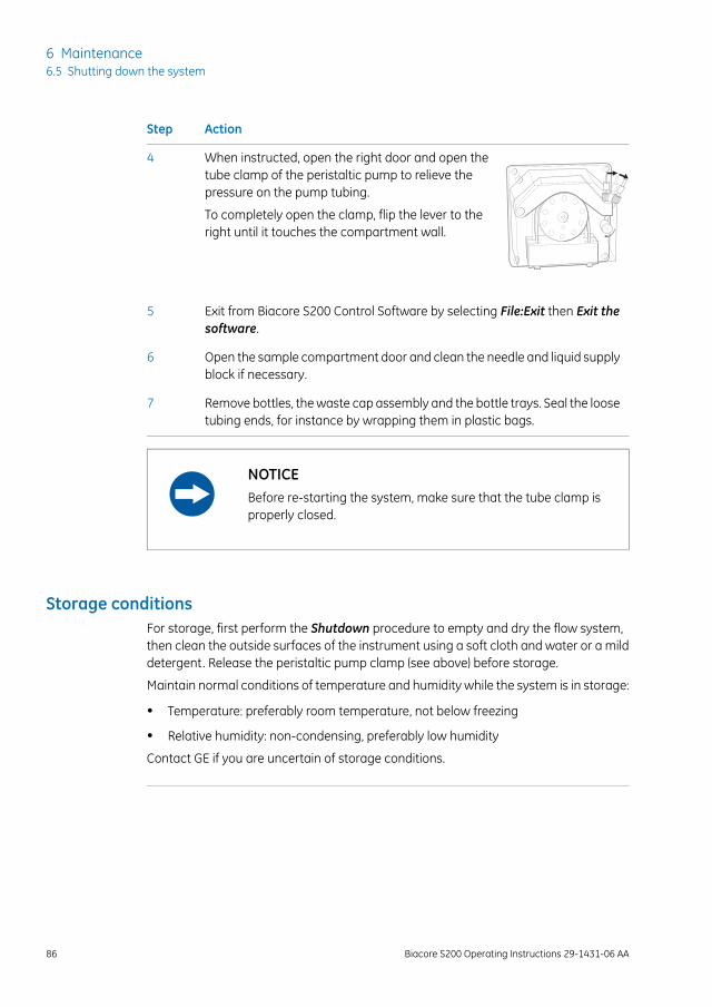
ActionStep
When instructed, open the right door and open thetube clamp of the peristaltic pump to relieve thepressure on the pump tubing.
To completely open the clamp, flip the lever to theright until it touches the compartment wall.
4
Exit from Biacore S200 Control Software by selecting File:Exit then Exit thesoftware.
5
Open the sample compartment door and clean the needle and liquid supplyblock if necessary.
6
Remove bottles, the waste cap assembly and the bottle trays. Seal the loosetubing ends, for instance by wrapping them in plastic bags.
7
NOTICEBefore re-starting the system, make sure that the tube clamp isproperly closed.
Storage conditionsFor storage, first perform the Shutdown procedure to empty and dry the flow system,then clean the outside surfaces of the instrument using a soft cloth and water or a milddetergent. Release the peristaltic pump clamp (see above) before storage.
Maintain normal conditions of temperature and humidity while the system is in storage:
• Temperature: preferably room temperature, not below freezing
• Relative humidity: non-condensing, preferably low humidity
Contact GE if you are uncertain of storage conditions.
86 Biacore S200 Operating Instructions 29-1431-06 AA
6 Maintenance6.5 Shutting down the system
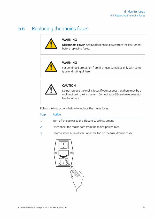
6.6 Replacing the mains fuses
WARNINGDisconnect power. Always disconnect power from the instrumentbefore replacing fuses.
WARNINGFor continued protection from fire hazard, replace only with sametype and rating of fuse.
CAUTIONDo not replace the mains fuses if you suspect that there may be amalfunction in the instrument. Contact your GE service representa-tive for advice.
Follow the instructions below to replace the mains fuses.
ActionStep
Turn off the power to the Biacore S200 instrument.1
Disconnect the mains cord from the mains power inlet.2
Insert a small screwdriver under the tab on the fuse drawer cover.3
Biacore S200 Operating Instructions 29-1431-06 AA 87
6 Maintenance6.6 Replacing the mains fuses
ActionStep
Prise open the fuse drawer cover.4
Replace both fuses.5
See the instrument product label for fuse ratings.
Close the fuse drawer cover and reconnect the mains supply.6
88 Biacore S200 Operating Instructions 29-1431-06 AA
6 Maintenance6.6 Replacing the mains fuses
7 Troubleshooting
About this chapterThis chapter gives a brief guide to troubleshooting procedures for problems withBiacore S200.
In this chapter
See pageSection
907.1 System-related problems
927.2 Assay-related problems
Biacore S200 Operating Instructions 29-1431-06 AA 89
7 Troubleshooting
7.1 System-related problems
Instrument hygieneA fundamental requirement for trouble-free operation of Biacore S200 is that the systemis kept clean and is maintained regularly according to the following guidelines:
• Always use fresh buffer and distilled water. If you prepare your own buffers, filterbuffer and water through a 0.22 µm filter to remove particles. Ready-to-use buffersfrom GE are filtered.
• Follow the recommended maintenance procedures as described in theMaintenancechapter of these Operating Instructions. Do not ignore maintenance schedule re-minders.
• If the system is used with particularly “sticky” molecules or complex mixtures suchas serum, clean the flow system thoroughly after each run.
• Leave the system in standby mode with freshly filtered distilled water or buffer whennot in use, or run the Shutdown procedure to empty the flow system. Do not leavethe instrument with liquid standing still in the flow system.
• Do not take the sensor chip out of its protective cassette. Dust or other particles onthe sensor chip surface can seriously interfere with detection.
Instrument considerations• If the PC does not seem to communicate with the instrument, check that the com-
munication cable is properly connected.
• Make sure there is adequate ventilation around at the instrument site.
• Check the accessible tube fittings on the pumps, buffer selector valve and degasserregularly for leaks.
• Make sure the clamp on the peristaltic pump is properly closed at the start of a run.If the clamp is not closed, buffer and water will not be supplied properly to the liquidsupply block.
Buffer considerations• Make sure that the correct buffer tubing is inserted into the buffer bottle(s). If you
are only using one buffer, you should use buffer tubing A. The syringe pumps will beempty and the response will be out of range if no buffer is supplied to the flow cell.
90 Biacore S200 Operating Instructions 29-1431-06 AA
7 Troubleshooting7.1 System-related problems
• Check that there is sufficient buffer in the buffer bottle(s) and water in the waterbottle at the start of a run.
Sample considerations• Make sure that you have sufficient sample and reagent in the vials and microplate.
The volumes specified in the software (see the Biacore S200 Software Handbook) areminimum volumes with due consideration for dead volumes in different vials andmicroplates. Larger volumes may be needed if you have problems with injection ofair in sample or reagent injections.
• Use only recommended vials and microplates. Always cap vials and cover microplateswith foil, using the products supplied for this purpose by GE.
• Use only recommended caps for vials and adhesive foil for microplates. Sampleevaporation from uncovered samples will both affect the sample concentration andreduce the volume, possibly resulting in injection of air. Use of unsuitable adhesivefoil may block the autosampler needle with adhesive.
For further helpIf you are experiencing instrument-related problems and are unable to identify and/orcorrect them, run System Check, then contact your GE service representative.
Biacore S200 Operating Instructions 29-1431-06 AA 91
7 Troubleshooting7.1 System-related problems
7.2 Assay-related problems
Ligand considerationsLoss of ligand activity on the surface of the sensor chip is a common source of applicationproblems.
• If you cannot immobilize sufficient ligand with retained analyte-binding capacity, tryalternative immobilization methods or use a capturing approach. In some cases itmay be sufficient to perform immobilization at a milder pH, or to avoid exposure ofthe ligand to immobilization buffer as far as possible. The immobilization wizardsupports dilution of ligand into immobilization buffer immediately before injection,for ligands that do not withstand extended exposure to immobilization conditions.
• Make sure that the ligand withstands regeneration conditions without loss of activity.If you cannot find suitable regeneration conditions, consider using a capturing ap-proach so that you use fresh ligand on the surface for each analysis cycle.
• If you plan to store sensor chips with immobilized ligand for later use, perform controlexperiments to establish that the ligand retains activity in the storage conditions.
• Make sure you choose the correct flow path for a run. If you inject samples over aflow cell where no ligand is immobilized, you will not see significant binding.
Sample considerations• Make sure the samples do not precipitate at the concentrations and buffer conditions
used. Even micro-precipitation on the surface can seriously disturb the detection (orin the worst case block the flow system), and is generally seen as excessive noiseand irregularities in the sensorgrams.
• Where possible, samples should be prepared in running buffer or similar conditions.Drastic changes in buffer composition between running buffer and sample can in-troduce artefacts that may be difficult to interpret.
For further helpSeveral Biacore publications provide guidance on design and execution of experiments.Contact GE for more information.
92 Biacore S200 Operating Instructions 29-1431-06 AA
7 Troubleshooting7.2 Assay-related problems
8 Reference information
About this chapterThis chapter provides technical specifications for Biacore S200 system.
In this chapter
See pageSection
948.1 Specifications
978.2 Chemical resistance
988.3 Health and Safety Declaration Form
Biacore S200 Operating Instructions 29-1431-06 AA 93
8 Reference information
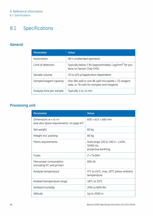
8.1 Specifications
General
ValueParameter
48 h unattended operationAutomation
Typically below 1 RU (approximately 1 pg/mm2 for pro-teins on Sensor Chip CM5)
Limit of detection
10 to 425 µl (application dependent)Sample volume
One 384 well or one 96 well microplate + 33 reagentvials, or 78 vials for samples and reagents
Sample/reagent capacity
Typically 2 to 15 minAnalysis time per sample
Processing unit
ValueParameter
600 × 615 × 680 mmDimensions w × d × h(see also Space requirements, on page 47)
60 kgNet weight
80 kgWeight incl. packing
Autorange 100 to 240 V~ ±10%,50/60 Hz,protective earthing
Mains requirements
2 × T4.0AHFuses
800 VAMax power consumption(including PC and printer)
4°C to 45°C, max. 20°C below ambienttemperature
Analysis temperature
18°C to 33°CAmbient temperature range
20% to 80% RHAmbient humidity
Up to 2000 mAltitude
94 Biacore S200 Operating Instructions 29-1431-06 AA
8 Reference information8.1 Specifications
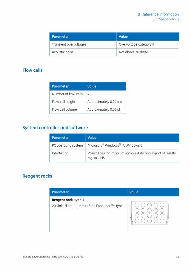
ValueParameter
Overvoltage category IITransient overvoltages
Not above 70 dB(A)Acoustic noise
Flow cells
ValueParameter
4Number of flow cells
Approximately 0.04 mmFlow cell height
Approximately 0.06 µlFlow cell volume
System controller and software
ValueParameter
Microsoft® Windows® 7, Windows 8PC operating system
Possibilities for import of sample data and export of results,e.g. to LIMS
Interfacing
Reagent racks
ValueParameter
Reagent rack, type 1
20 vials, diam. 11 mm (1.5 ml Eppendorf™-type)
Biacore S200 Operating Instructions 29-1431-06 AA 95
8 Reference information8.1 Specifications
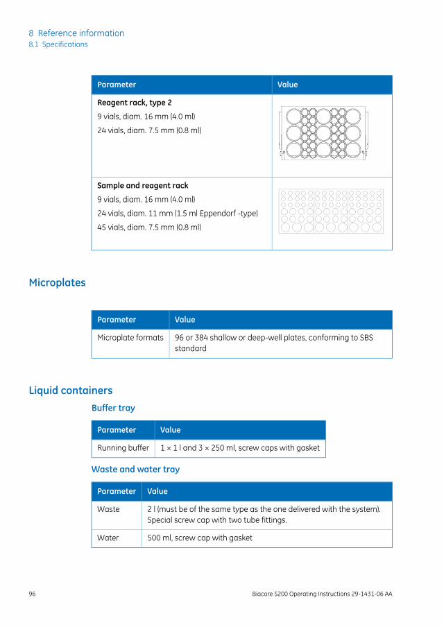
ValueParameter
Reagent rack, type 2
9 vials, diam. 16 mm (4.0 ml)
24 vials, diam. 7.5 mm (0.8 ml)
Sample and reagent rack
9 vials, diam. 16 mm (4.0 ml)
24 vials, diam. 11 mm (1.5 ml Eppendorf -type)
45 vials, diam. 7.5 mm (0.8 ml)
Microplates
ValueParameter
96 or 384 shallow or deep-well plates, conforming to SBSstandard
Microplate formats
Liquid containersBuffer tray
ValueParameter
1 × 1 l and 3 × 250 ml, screw caps with gasketRunning buffer
Waste and water tray
ValueParameter
2 l (must be of the same type as the one delivered with the system).Special screw cap with two tube fittings.
Waste
500 ml, screw cap with gasketWater
96 Biacore S200 Operating Instructions 29-1431-06 AA
8 Reference information8.1 Specifications
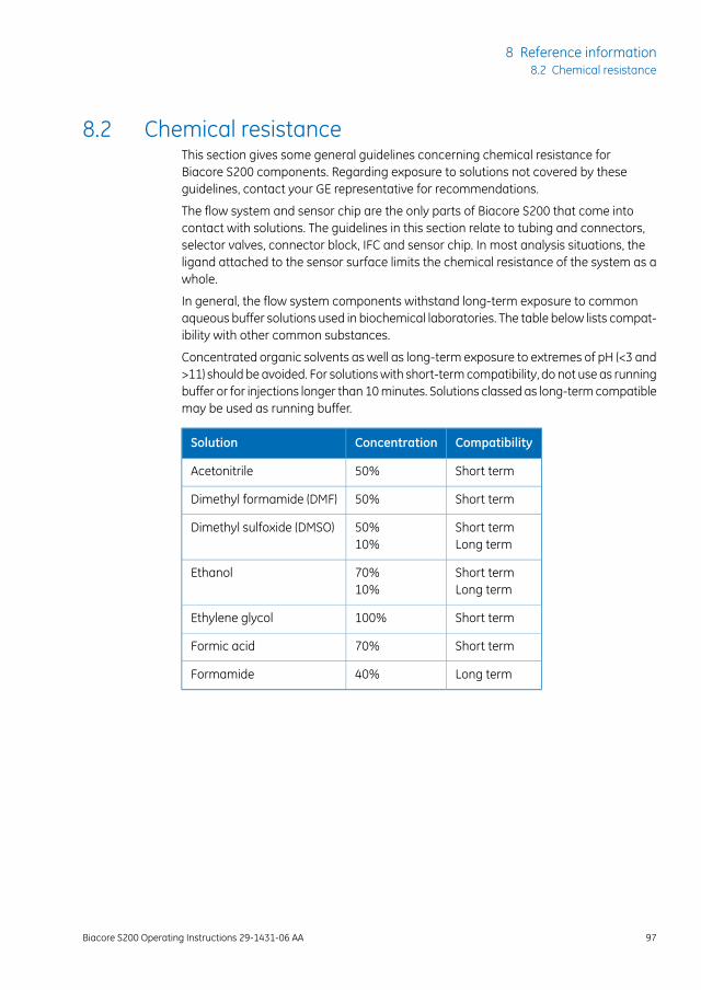
8.2 Chemical resistanceThis section gives some general guidelines concerning chemical resistance forBiacore S200 components. Regarding exposure to solutions not covered by theseguidelines, contact your GE representative for recommendations.
The flow system and sensor chip are the only parts of Biacore S200 that come intocontact with solutions. The guidelines in this section relate to tubing and connectors,selector valves, connector block, IFC and sensor chip. In most analysis situations, theligand attached to the sensor surface limits the chemical resistance of the system as awhole.
In general, the flow system components withstand long-term exposure to commonaqueous buffer solutions used in biochemical laboratories. The table below lists compat-ibility with other common substances.
Concentrated organic solvents as well as long-term exposure to extremes of pH (<3 and>11) should be avoided. For solutions with short-term compatibility, do not use as runningbuffer or for injections longer than 10 minutes. Solutions classed as long-term compatiblemay be used as running buffer.
CompatibilityConcentrationSolution
Short term50%Acetonitrile
Short term50%Dimethyl formamide (DMF)
Short termLong term
50%10%
Dimethyl sulfoxide (DMSO)
Short termLong term
70%10%
Ethanol
Short term100%Ethylene glycol
Short term70%Formic acid
Long term40%Formamide
Biacore S200 Operating Instructions 29-1431-06 AA 97
8 Reference information8.2 Chemical resistance
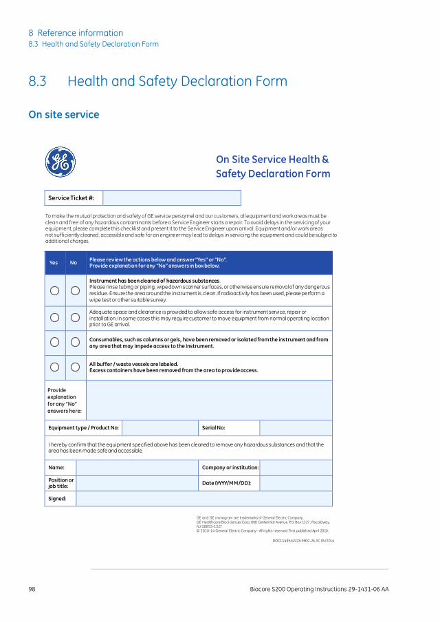
8.3 Health and Safety Declaration Form
On site service
On Site Service Health &
Safety Declaration Form
Service Ticket #:
To make the mutual protection and safety of GE service personnel and our customers, all equipment and work areas must be clean and free of any hazardous contaminants before a Service Engineer starts a repair. To avoid delays in the servicing of your equipment, please complete this checklist and present it to the Service Engineer upon arrival. Equipment and/or work areas not sufficiently cleaned, accessible and safe for an engineer may lead to delays in servicing the equipment and could be subject to additional charges.
Yes No Please review the actions below and answer “Yes” or “No”. Provide explanation for any “No” answers in box below.
Instrument has been cleaned of hazardous substances. Please rinse tubing or piping, wipe down scanner surfaces, or otherwise ensure removal of any dangerous residue. Ensure the area around the instrument is clean. If radioactivity has been used, please perform a wipe test or other suitable survey.
Adequate space and clearance is provided to allow safe access for instrument service, repair or installation. In some cases this may require customer to move equipment from normal operating location prior to GE arrival.
Consumables, such as columns or gels, have been removed or isolated from the instrument and from any area that may impede access to the instrument .
All buffer / waste vessels are labeled. Excess containers have been removed from the area to provide access.
Provide
explanation
for any “No”
answers here:
Equipment type / Product No: Serial No:
I hereby confirm that the equipment specified above has been cleaned to remove any hazardous substances and that the area has been made safe and accessible.
Name: Company or institution:
Position or job title:
Date (YYYY/MM/DD):
Signed:
GE and GE monogram are trademarks of General Electric Company. GE Healthcare Bio-Sciences Corp, 800 Centennial Avenue, P.O. Box 1327, Piscataway, NJ 08855-1327 © 2010-14 General Electric Company—All rights reserved. First published April 2010.
DOC1149542/28-9800-26 AC 05/2014
98 Biacore S200 Operating Instructions 29-1431-06 AA
8 Reference information8.3 Health and Safety Declaration Form
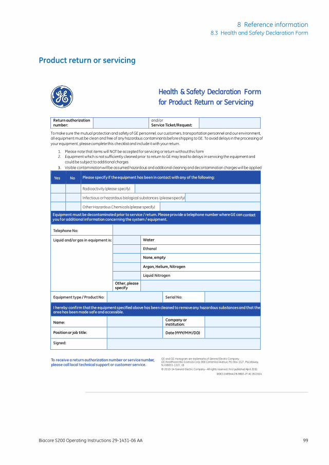
Product return or servicing
Health & Safety Declaration Form
for Product Return or Servicing
Return authorization number:
and/or Service Ticket/Request:
To make sure the mutual protection and safety of GE personnel, our customers, transportation personnel and our environment,
all equipment must be clean and free of any hazardous contaminants before shipping to GE. To avoid delays in the processing of
your equipment, please complete this checklist and include it with your return.
1. Please note that items will NOT be accepted for servicing or return without this form
2. Equipment which is not sufficiently cleaned prior to return to GE may lead to delays in servicing the equipment and
could be subject to additional charges
3. Visible contamination will be assumed hazardous and additional cleaning and decontamination charges will be applied
Yes No Please specify if the equipment has been in contact with any of the following:
Radioactivity (please specify)
Infectious or hazardous biological substances (please specify)
Other Hazardous Chemicals (please specify)
Equipment must be decontaminated prior to service / return. Please provide a telephone number where GE can contact you for additional information concerning the system / equipment.
Telephone No:
Liquid and/or gas in equipment is: Water
Ethanol
None, empty
Argon, Helium, Nitrogen
Liquid Nitrogen
Other, please specify
Equipment type / Product No:
Serial No:
I hereby confirm that the equipment specified above has been cleaned to remove any hazardous substances and that the area has been made safe and accessible.
Name: Company or
institution:
Position or job title: Date (YYYY/MM/DD)
Signed:
To receive a return authorization number or service number, please call local technical support or customer service.
GE and GE monogram are trademarks of General Electric Company. GE Healthcare Bio-Sciences Corp, 800 Centennial Avenue, P.O. Box 1327, Piscataway, NJ 08855-1327, US
© 2010-14 General Electric Company—All rights reserved. First published April 2010.
DOC1149544/28-9800-27 AC 05/2014
Biacore S200 Operating Instructions 29-1431-06 AA 99
8 Reference information8.3 Health and Safety Declaration Form

Appendix ASoftware tool texts
The on-screen instructions in the maintenance, test and service software tools are givenin English. Translations to other languages are provided in the local language versionsof these Operating Instructions.
100 Biacore S200 Operating Instructions 29-1431-06 AA
A Software tool texts
Appendix BTechnical description
About this appendixThis appendix gives a brief description of technical aspects of Biacore S200.
In this appendix
See pageSection
102B.1 Detection principle
104B.2 Buffer and sample handling
Biacore S200 Operating Instructions 29-1431-06 AA 101
B Technical description
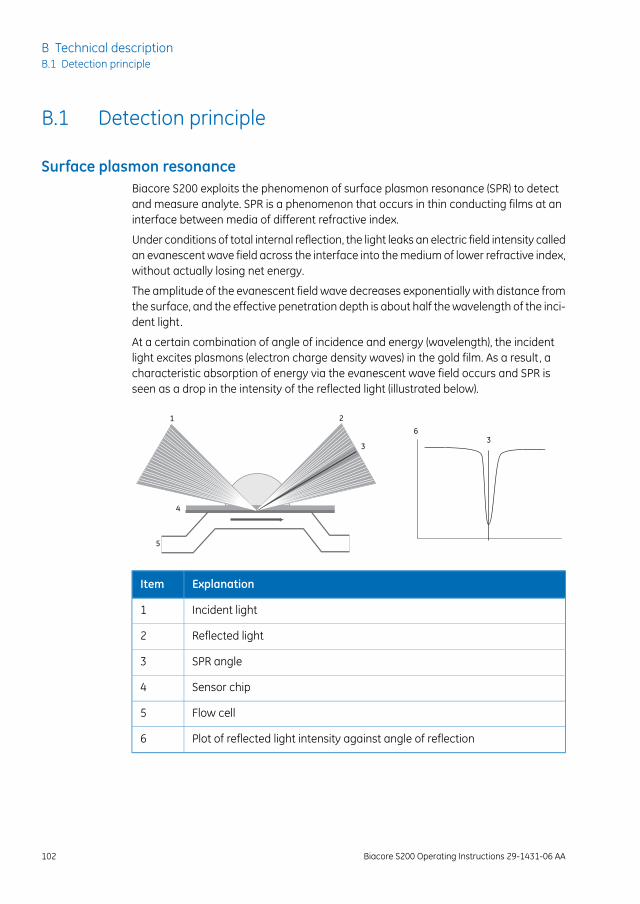
B.1 Detection principle
Surface plasmon resonanceBiacore S200 exploits the phenomenon of surface plasmon resonance (SPR) to detectand measure analyte. SPR is a phenomenon that occurs in thin conducting films at aninterface between media of different refractive index.
Under conditions of total internal reflection, the light leaks an electric field intensity calledan evanescent wave field across the interface into the medium of lower refractive index,without actually losing net energy.
The amplitude of the evanescent field wave decreases exponentially with distance fromthe surface, and the effective penetration depth is about half the wavelength of the inci-dent light.
At a certain combination of angle of incidence and energy (wavelength), the incidentlight excites plasmons (electron charge density waves) in the gold film. As a result, acharacteristic absorption of energy via the evanescent wave field occurs and SPR isseen as a drop in the intensity of the reflected light (illustrated below).
1 2
3
4
5
63
ExplanationItem
Incident light1
Reflected light2
SPR angle3
Sensor chip4
Flow cell5
Plot of reflected light intensity against angle of reflection6
102 Biacore S200 Operating Instructions 29-1431-06 AA
B Technical descriptionB.1 Detection principle
Because the evanescent wave field penetrates the solution, conditions for this resonanceeffect are sensitive to the refractive index of the solution within the effective penetrationdepth of the evanescent field. Changes in solute concentration at the surface of thesensor chip cause changes in the refractive index of the solution, which is measured asa changes in the SPR angle.
The reduced intensity of reflected light is not caused by light absorption in thesample in the conventional (transmission spectroscopy) sense. The light usedto generate the signal is totally internally reflected inside the optical unit, andit is the evanescentwave that penetrates the sample. Consequently,measure-ments can be made on turbid or even opaque solutions, without interferencefrom conventional light absorption or scattering by the sample.
Note:
What SPR measuresIn the configuration used in Biacore S200, the SPR response is a measure of the refractiveindex of the solution within the penetration distance of the evanescent field wave. Thisdistance (about 300 nm) is small in relation to the height of the flow cell, so that SPR ef-fectively measures the refractive index at the surface of the sensor chip.
The refractive index of the solution varies with the solute content. When the detectingmolecule is attached to the sensor chip or when analyte binds to the detecting molecule,the solute concentration at the sensor chip surface increases, leading to a change inthe SPR signal.
The response measured in Biacore S200 is related to the mass of analyte bound and islargely independent of the nature of the analyte. Refractive index contributions for dif-ferent solutes are additive, so that the amount of detecting molecule attached and theamount of analyte bound can both be measured with the same detection principle.
Biacore S200 Operating Instructions 29-1431-06 AA 103
B Technical descriptionB.1 Detection principle
B.2 Buffer and sample handling
Flow systemTwo high performance syringe pumps and one peristaltic pump handle the distributionof buffer and water to the IFC and the liquid supply block.
One syringe pump maintains a low flow of buffer through the IFC. The second syringepump is used for aspiration of samples and reagents, and precision delivery to the sensorchip surface via the IFC. The system switches automatically between these pumps asrequired.
The peristaltic pump continuously supplies buffer and water to the liquid supply block.The buffer supplied to the liquid supply block is used for washing the injection needle.The buffer flow also helps keeping the liquid supply block clear of precipitated buffer.
Water supplied to the liquid supply block is used for rinsing the needle and the liquidsupply block itself.
Effluent from the IFC and the liquid supply block is conveyed to the waste bottle.
The flow system is illustrated schematically below.
104 Biacore S200 Operating Instructions 29-1431-06 AA
B Technical descriptionB.2 Buffer and sample handling
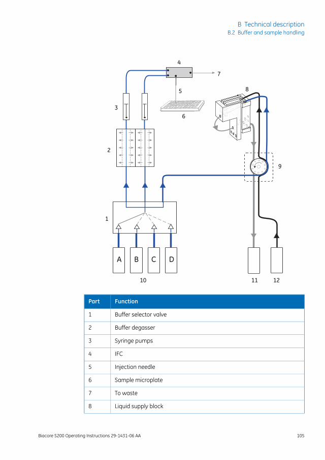
A DCB
1
2
3
4
5
6
7
8
9
10 11 12
FunctionPart
Buffer selector valve1
Buffer degasser2
Syringe pumps3
IFC4
Injection needle5
Sample microplate6
To waste7
Liquid supply block8
Biacore S200 Operating Instructions 29-1431-06 AA 105
B Technical descriptionB.2 Buffer and sample handling
FunctionPart
Peristaltic pump9
Buffer bottles10
Waste bottle11
Water bottle12
Buffer degasserThe degasser consists of independent vacuum chambers, each containing membranetubing, which is permeable to small gas molecules.
Each of the two buffer tubes from the selector valve is connected to a separate vacuumchamber. A vacuum pump maintains a low pressure in the vacuum chambers, therebydrawing gas molecules through the membrane tubing.
Valves in the degasser switch pump input between the vacuum chambers and atmo-sphere. This keeps the pump clean and increases the service life of the degasser. Anactive carbon filter provides added protection for the vacuum pump.
Cooling unitA maintenance-free cooling unit based on Peltier elements is located behind the samplecompartment. Contact your GE service representative if the sample compartment warmsup in spite of a low temperature setting.
106 Biacore S200 Operating Instructions 29-1431-06 AA
B Technical descriptionB.2 Buffer and sample handling
IndexAAdjust rack tray, 62Ambient environment, 49Autosampler, 33
BBIAdesorbsolution, 73BIAdisinfectant solution, 73BIAmaintenance Kit, 73BIAnormalizing solution, 73BIAtest solution, 73Buffers, 56Buffer selector valve, 30Buffer tray, 30
CCE
conformity, 9CE marking, 10Change reagent rack, 66Checking for leaks, 76Chemical resistance, 97Cleaning the instrument, 75Cleaning the sample compart-ment, 82Computer connection, 51Connected equipment, 11
DDegasser, 30Disposal, 24
EEject rack tray, 60Emergency procedures, 22
power failure, 23Environmental conditions, 49Environmental conformity, 10
FFinish a run, 68Flammable liquids, 15Flow cells, 95
GGeneral precautions, 14
IIFC, 41Install rack tray, 67Instrument overview, 28Integrated µ-Fluidic Car-tridge, 41Intended use, 7International standards, 9
LLeaks, 76Liquid handling system, 40Liquid supply block, 33Liquid system setup, 58Lithium battery, 24
MMains power connection, 52Maintenance Kit, 73Maintenance summary, 72Manufacturing information, 9Microplates, 37, 96
NNormalizing the detector, 78Notes and tips, 8
OOpen sample compartment, 81
PPeristaltic pump, 31Personal protection, 16Power requirements, 48Power switch, 36Preparing reagents, 64Preparing samples, 63Prerequisites, 7
RRack tray, 37
Biacore S200 Operating Instructions 29-1431-06 AA 107
Index
adjusting, 62ejecting, 60installing, 67
Reagent preparation, 64Reagent rack, 38Reagent racks, 95Recycling, 24Recycling information
decontamination, 24disposal of electrical compo-nents, 24
Regulatory information, 9Replacing fuses, 87
SSafety
notices, 8precautions, 14
Sample and reagent rack, 39Sample compartment, 33
cleaning, 82opening, 81
Sample preparation, 63Sensor chip, 41
inserting, 56Sensor Chip Maintenance, 73
Sensor chip port, 34Set temperature, 59Shutdown, 85Space requirements, 47Specifications, 94Standby, 68, 85Start a run, 68Start the system, 55Status indicators, 35Storage conditions, 86Syringe pumps, 30System check, 79System startup, 55
TTemperature control, 43Troubleshooting, 89Typographical conventions, 6
UUser information, important, 7
WWash buffer tubing, 68Waste and water tray, 29
108 Biacore S200 Operating Instructions 29-1431-06 AA
Index

Page intentionally left blank
GE and GE monogram are trademarks of General Electric Company.
Biacore is a trademark of General Electric Company or one of its subsidiaries.
Microsoft and Windows are registered trademarks of Microsoft Corporation.
Eppendorf is a trademark of Eppendorf AG.
All other third party trademarks are the property of their respective owner.
Any use of Biacore S200 Control Software is subject to GE Healthcare StandardSoftware End-User License Agreement for Life Sciences Software Products. Acopy of this Standard Software End-User License Agreement is available on re-quest.
© 2015 General Electric Company – All rights reserved.First published May 2015
All goods and services are sold subject to the terms and conditions of sale ofthe company within GE Healthcare which supplies them. A copy of these termsand conditions is available on request. Contact your local GE Healthcare repre-sentative for the most current information.
GE Healthcare Bio-Sciences ABBjörkgatan 30, 751 84 Uppsala, Sweden
GE Healthcare Europe GmbHMunzinger Strasse 5, D-79111 Freiburg, Germany
GE Healthcare Bio-Sciences Corp.800 Centennial Avenue, P.O. Box 1327, Piscataway, NJ 08855-1327, USA
GE Healthcare Japan CorporationSanken Bldg. 3-25-1, Hyakunincho Shinjuku-ku, Tokyo 169-0073, Japan
For local office contact information, visitwww.gelifesciences.com/contact
GE Healthcare UK LimitedAmersham PlaceLittle ChalfontBuckinghamshire, HP7 9NAUnited Kingdom
www.gelifesciences.com/biacore
29-1431-06 AA 04/2015 a25