big area additive manufacturing and hardware-in-the …web.ornl.gov/sci/manufacturing/docs/pubs/big...
TRANSCRIPT

AbstractRapid vehicle powertrain development has become a technological breakthrough for the design and implementation of vehicles that meet and exceed the fuel efficiency, cost, and performance targets expected by today’s consumer. Recently, advances in large scale additive manufacturing have provided the means to bridge hardware-in-the-loop with preproduction mule chassis testing. This paper details a case study from Oak Ridge National Laboratory bridging the powertrain-in-the-loop development process with vehicle systems implementation using big area additive manufacturing (BAAM). For this case study, the use of a component-in-the-loop laboratory with math-based models is detailed for the design of a battery electric powertrain to be implemented in a printed prototype mule. The ability for BAAM to accelerate the mule development process via the concept of computer-aided design to part is explored. The integration of the powertrain and the opportunities and challenges of doing so are detailed in this work. The results of the mule-vehicle chassis dynamometer testing are presented. Lastly, the ability to integrate more complex powertrains is discussed.
IntroductionIn model-based development of vehicle powertrains, through hardware-in-the-loop (HIL) to mule integration, a new enabling design tool is emerging from recent advances in large scale additive manufacturing (AM) that has become known as big area additive manufacturing (BAAM). AM creates components directly from a computer model. This is an “additive” process, where material is added to build a component, as opposed to a “subtractive” process such as machining, where material is removed from a billet to manufacture a component. AM is well-suited for rapid prototyping as it is extremely flexible and enables the rapid creation of very complex geometries with minimal waste. This technology could be transformative for many sectors including automotive.
One of the most promising aspects of AM is the ability to produce a part directly from computer-based geometry files with very few limitations. The literature has already documented some use of AM for automotive prototyping applications for both metals and polymers. And studies on using AM for metals and polymers in automotive applications are continuing, including examples of using metal additive processes for complex parts [1] and pistons [2]. The popular imagination has been inspired by articles such as the 2009 Popular Mechanics article by Jay Leno on the use of a 3-D printer to replicate legacy parts [3].
Polymer AM can facilitate the rapid manufacture of lightweight, complex components and impact a broad spectrum of manufacturing industries. Until recently, AM processes were constrained to relatively small scales for both polymers and metals. The polymer AM processes used in these applications and studies have been limited in scale due to the constraint of needing reduced oxygen and constant heat environments. In addition, there are some issues with residual stresses during the AM process with both metals and polymers that have made larger scale printed parts difficult to produce with precision and dimensions needed for automotive applications. Recent advances in BAAM with polymers and composites have enabled larger scales. Conventional polymer additive systems are capable of producing workpieces in the size range of less than a few cubic feet in volume. The BAAM systems from Cincinnati Incorporated [4] now have the ability to print pieces on the order of 1,000 cubic feet. The initial BAAM systems were the result of co-development by Oak Ridge National Laboratory (ORNL) and Lockheed Martin.
The ability to directly print a large, complex working part directly from a computer-aided design (CAD) file with these BAAM systems allows for direct generation of parts such as welded tube frames and body-in-white as opposed to conventional mule manufacturing processes. To date however, there have only been limited efforts to use large scale AM for vehicles. For example, in 2013 Wired reported on the Urbee [5], and in 2014, ORNL, CI, and Local Motors printed a
Big Area Additive Manufacturing and Hardware-in-the-Loop for Rapid Vehicle Powertrain Prototyping: A Case Study on the Development of a 3-D-Printed Shelby Cobra
2016-01-0328
Published 04/05/2016
Scott Curran, Paul Chambon, Randall Lind, Lonnie Love, Robert Wagner, Steven Whitted, David Smith, Brian Post, Ronald Graves, Craig Blue, Johney Green, and Martin KellerOak Ridge National Laboratory
CITATION: Curran, S., Chambon, P., Lind, R., Love, L. et al., "Big Area Additive Manufacturing and Hardware-in-the-Loop for Rapid Vehicle Powertrain Prototyping: A Case Study on the Development of a 3-D-Printed Shelby Cobra," SAE Technical Paper 2016-01-0328, 2016, doi:10.4271/2016-01-0328.
Copyright © 2016 SAE International
Downloaded from SAE International by Oak Ridge National Laboratory, Tuesday, June 28, 2016

vehicle named the “Strati” at a trade show using a BAAM system [6]. The development of Strati as part of a cooperative research and development agreement with ORNL was detailed in [7]. Some recent studies have been published based on these and similar projects [8].
This paper will focus on the combined use of a BAAM system and HIL for rapid vehicle prototyping. HIL is deployed to develop the powertrain and its controls with the same accelerated time frame achieved by BAAM to create the vehicle chassis. In a larger context, HIL platforms are used to analyze any component or subsystem in a virtual vehicle environment. The platforms are valuable for developing controls in a safe, controlled environment where global systems are simulated using physics-based models. Typically a HIL platform consists of a real-time run-time computer running a model of the complete vehicle, except for the component under test in the test cell, and input/output cards to interact with sensors and actuators and handle communications that this component would experience in a real vehicle. With this environment in place, the component under test “thinks” that it is installed on a vehicle driving in real-world conditions. In the rest of this paper, HIL might be replaced by “X”-in-the-loop, where X is any component tested on the HIL platform (X could be a motor, powertrain, controller, etc.).
Previous studies have examined the use of HIL systems for powertrain control system software verification and validation going back more than a decade [9]. These systems are used extensively in the US Department of Energy (DOE) Advanced Vehicle Technical Competition series [10]. Studies examining HIL systems for electric motors in vehicle powertrains have also been completed, focusing on integration of individual components such as electric motors [11]. HIL testing benefits include
• flexibility to change virtual vehicle architectures and experimental conditions,
• accuracy of real engine and after treatment measurements, • repeatability of a controlled transient operating environment, and • lower costs and safer environment compared with track or
onroad vehicle analysis
In general, HIL is a phase of the development cycle that follows offline simulation and precedes vehicle implementation, as detailed in the following description.
1. Offline Simulation ◦ Component sizing and selection ◦ Performance prediction ◦ Control strategies development
2. Motor-in-the-Loop ◦ Motor installed in dynamometer cell ◦ Interface validation ◦ Performance testing ◦ Control strategies refinement
3. Powertrain-in-the-Loop ◦ Motor, battery and other components of electric drivetrain
installed in dynamometer cell ◦ Interface validation ◦ Performance testing
◦ Control strategies refinement 4. Vehicle Implementation
◦ Powertrain installation in vehicle ◦ Performance testing ◦ Control strategies refinement
This paper documents the opportunities and challenges associated with the use of BAAM for rapid prototyping of vehicles using a printed Shelby Cobra replica as the case study. In particular, the concept of printed mules being an extension of HIL powertrain development is explored. This study did not focus on the development of specific vehicle performance targets. The DOE Advanced Manufacturing Office and ORNL funded the development of the car, while the ORNL National Transportation Research Center’s (NTRC’s) contributions in designing the powertrain, machining the components, wiring the car, and developing the control systems were enabled by the long-standing vehicles program funded by the DOE Vehicle Technologies Office.
Big Area Additive Manufacturing for Printed Vehicle PrototypeThe use of a BAAM system, the development of the vehicle architecture, the implementation of the powertrain, and the evaluation of the vehicle are presented in the next sections.
The new BAAM system, which was jointly developed by ORNL and CI [12,13], is able to print polymer components at speeds 500 to 1,000 times faster and 10 times larger than is possible with current industrial additive machines. These systems are able to produce very large components, including those on the order of a vehicle frame, from pellets and provide a very unique resource for rapid vehicle prototyping.
The BAAM system used for this project was a polymer-extruded nozzle fitted to a multiaxis computer-aided servo system. Other key features include the use of a 0.2 in. diameter nozzle, resulting in a 0.030 in. surface variation. Figure 1 shows a BAAM extruder. The BAAM system shown in Figure 2 was capable of deposition rates of about 20 lb/hour. In addition, the pellets used for printing were relatively inexpensive, typically under $5/lb. Table 1 gives the characteristics of the extruder shown in Figure 1.
Figure 1. BAAM system extruder.
Downloaded from SAE International by Oak Ridge National Laboratory, Tuesday, June 28, 2016

Figure 2. BAAM system installed at the ORNL Manufacturing Demonstration Facility.
Table 1. BAAM system extruder characteristics.
Use of Carbon Fiber Reinforced ABSFor this case study, a carbon fiber reinforced ABS plastic was used. This is a relatively new concept in which chopped carbon fiber is blended with a thermoplastic. Previous experiments had determined that a blend of carbon fiber higher than 15%-20% led to significant reduction in warping out of the oven, detailed in a recent study on the effects of adding carbon fiber to ABS [14]. The effect on curl is apparent, as shown in Figure 3. This behavior makes the addition of carbon fiber an enabling technology for large printed workpieces and can eliminate the need for additional ovens to prevent curling. Carbon fiber reinforced ABS shows increased strength and significant reduction in distortion. Additional details on carbon fiber- filled ABS for large scale printing can be found in [14] and [15].
Figure 3. Effect of carbon fiber addition to ABS on workpiece curl from [14].
Vehicle Mechanical DesignThe mechanical design of the vehicle body and frame was driven by the drivetrain, suspension, and battery components already selected (as described in the next section) and by the special requirements of 3-D printing with the carbon fiber-reinforced ABS polymer. A number of different body styles were considered before settling on the classic Shelby Cobra shape. The Cobra body provided sufficient interior room for the preselected components and had the advantage of available aftermarket accessories such as windshield, bumpers, and lights. Open-source surface models of the Cobra body were also available, which reduced modeling time considerably. SolidWorks design software was used for all mechanical modeling.
The vehicle frame was designed specifically for 3-D printing that keeps stresses below 1,000 psi and provides fasteners to prevent possible delamination between the horizontally printed layers.
Figure 4. CAD of printed Cobra.
Finite element analysis (FEA) shows that with the frame loaded to 2,000 lbf (1,000 lbf per side), near mid-span the stress is under 600 psi (Figure 5), and maximum deflection is under 0.35 in. (Figure 6). The polymer frame mass is about 260 lb.
Figure 5. FEA stress results for frame loading of 2,000 lbf.
Downloaded from SAE International by Oak Ridge National Laboratory, Tuesday, June 28, 2016

Figure 6. FEA displacement results for frame loading of 2,000 lbf.
The polymer frame could not be designed with sufficient torsional stiffness within the envelope restrictions, so a metal torsion bar was added between the firewall and rear of the cockpit (Figure 7).
Figure 7. Torsional bar stiffener system.
The vehicle body consists of front, middle, and rear deck single bead (0.22 in. thick) sections with multiple bonded stiffeners and internal supports. The front and rear sections are removable for maintenance access. Figure 8 shows these body details. All of these body panels were printed using the BAAM system shown in Figure 2 and have a combined mass of about 430 lb.
Figure 8. CAD of printed Cobra body, frame, and supports.
The stereolithography (STL) files were sent to the BAAM processing unit as described in the next section.
Printing DetailsAs with conventional additive manufacturing, CAD files were transformed into STL files and input into a slicing program that transformed the three-dimensional geometry to machine tool path commands. Printing the frame was completed in one process taking approximately 12 hours. This rate is 500 times above that normally associated with polymer AM processes. It should be noted that a newer BAAM co-developed by ORNL and Cincinnati Incorporated is capable of printing larger pieces at a maximum deposition rate of 100 lb/hour. Figures 9 and 10 show the Cobra frame being printed on the BAAM system.
Figure 9. Cobra frame being printed on the BAAM system.
Figure 10. The computer-controlled extruder follows instructions for path and deposition rate.
The total time to print the frame was approximately 12 hours and required approximately 260 lb of carbon fiber-reinforced ABS. The frame was allowed to cool on the work surface for 4 hours before removal to ensure the part had completely solidified and was safe to handle. Figure 11 shows the completed frame.
The total weight of the printed components was approximately 690 lb. The frame took approximately 12 hours, the skins 8 hours, and the supports 4 hours to print. No attempts at lightweighting were made for this case study. Instead, components were printed for robustness and workability.
Downloaded from SAE International by Oak Ridge National Laboratory, Tuesday, June 28, 2016

Figure 11. Completed frame after cooling.
Lamination CharacteristicsAs with any layered process, BAAM exhibits anisotropic mechanical properties. The carbon fiber aligns with the tool path direction, providing manufacturing-controlled strength and stiffness. The weakest direction of the parts was between layers. To help with the integrity of the frame, drivetrain components were attached with threaded rods that put the layers in compression.
Hardware-in the Loop Development of Electric Vehicle PowertrainThis section describes development of the printed Cobra powertrain, including component sizing from simulations, integration into the HIL system, and development of the controls.
Offline SimulationThe powertrain options were modeled in a physics-based vehicle system simulation program, Autonomie, developed for DOE by Argonne National Laboratory [16]. A model for a battery electric vehicle (BEV) with rear wheel drive from a traction motor mated to a gearbox was built as shown in Figure 12 and was used for simulations for component selection. As illustrated in Figure 13, the offline simulation stage only considers virtual components making up the complete vehicle model. No hardware is physically present.
Figure 12. BEV model for component selection and controls development.
Figure 13. Vehicle simulation step: 100% simulation.
Component SelectionVehicle systems simulations were used for component sizing. Electrical consumption over multiple drive cycles was used as the baseline to determine the required energy storage system (ESS) capacity. Due to the accelerated nature of the project, components under consideration were limited to commercially available powertrain components using controller area network (CAN) communications.
For this vehicle, a 4.5 kWh LiFePO4 battery pack from A123 was selected. The 14 Ah battery pack features CAN communications and a built-in battery management system, meaning that it is a turnkey solution. The relatively small ESS could be fit in the nose of the printed Cobra and was shown in vehicle systems simulations to provide around a 22 mile all electric range at 80% depth of discharge.
Traction motor options were evaluated using vehicle systems simulations over the US Environmental Protection Agency (EPA) urban dynamometer driving schedule (UDDS), Japan 10/15, EPA highway fuel economy test (HWFET), and US 06 driving schedules. The UDDS and Japan 10/15 modes more closely represent the prescribed duty cycle for vehicles (low speed, mild accelerations). The EPA HWFET and the supplemental EPA US06 were used as references for higher speed and more aggressive driving behavior. It was found that a 50 kW machine would be sufficient to provide power for all examined driving schedules. An example of a simulation of the traction motor operation during a US06 cycle is shown in Figure 14. An HBM120 TM 4 motor and CO150 TM4 inverter were selected. A single speed gearbox mating to the TM4 traction motor was provided by GKN Driveline.
Downloaded from SAE International by Oak Ridge National Laboratory, Tuesday, June 28, 2016

Figure 14. Simulation of traction motor operating points on US06 cycle (torque vs. speed). Blue points represent instantaneous electric machine operating points (speed and torque) as the vehicle drives through the US06 cycle. Thin blue and red lines are the maximum and minimum torque curves for the TM4.
An air-cooled SAE J1772 compliant Brusa 3.3 kW onboard charger was selected. This charger uses CAN communications and allows the printed Cobra to use any available electric vehicle supply equipment (EVSE) or charging. Also a 4 kW DC-DC converter was integrated in the high voltage architecture to maintain the 12 V battery as all controllers and cooling components are powered off the 12 V bus. Those low voltage loads are compensated by the high voltage battery thanks to the DC-DC converter. The final powertrain configuration is shown in Figure 15.
Figure 15. Printed Cobra BEV architecture.
Hardware-in-the-Loop Platform for Vehicle Controls PrototypingThe capabilities at the NTRC, where vehicle modeling and testing were performed, include powertrain test cells with two 500 kW transient dynamometers suitable for Class 8 truck powertrain testing and a component test cell, shown in Figure 16, designed to handle smaller, individual, components such as engines or traction motors. They share a 400 kW ESS and are each equipped with a dSPACE HIL real-time platform.
Figure 16. Printed Cobra traction motor installed in ORNL component test cell in the NTRC loop laboratory.
The component test cell was used for this study. It is very well suited for electric drivetrain testing thanks to a 250 kW, 12,000 rpm low inertia dynamometer and the 400 kW battery emulator, which can mimic any battery chemistry behavior thanks to its own real-time model and voltage and current operation ranges of respectively [0;800]V and [-600;600]A.
Component-in-the-LoopFollowing the simulation study and component selection, as components became available they were installed in the component test cell. At the same time, yet-to-be-procured vehicle components and the vehicle chassis were modeled on the HIL real-time platform.
The electric traction motor and inverter were tested first, as shown in Figure 17. The HIL platform controlled both the dynamometer, to mimic the mechanical speeds and loads experienced by the motor under real world conditions, and the battery emulator, to emulate voltage and current conditions that would occur on a battery pack under those same conditions. The HIL platform also generates all CAN communications coming from virtual vehicle components as if those units were physically present with the motor and inverter in the test cell. This duplicates the environment the motor will experience in a real vehicle. The battery emulator simulated the ESS and provided electric power to the motor.
This phase allowed validation of the interface between the vehicle supervisory controller and the traction motor, debugging of some of the vehicle level controls, and test vehicle performance with limited hardware.
Downloaded from SAE International by Oak Ridge National Laboratory, Tuesday, June 28, 2016

Powertrain-in-the-LoopThe next phase was powertrain-in-the-loop testing, where all electric drive components were physically installed in the dynamometer cell. This included the motor, inverter, battery pack, DC-DC converter, high voltage distribution box, vehicle supervisory controller, driver interface, and onboard charger. The real-time platform emulated the rest of the vehicle (transmission, driveline, wheels, chassis, driver, and drive cycle) and controlled the dynamometer to subject the motor
and electric drive to real-world speed and loads based on the vehicle model. The powertrain-in-the-loop provided a safe and controlled environment to design, construct, debug, and validate the system. This included the low and high voltage wiring harness, all communications and component-to-component interactions, and the control strategies. Figure 18 illustrates the increased use of hardware in this step. This phase allowed validation of all vehicle communications and wiring harnesses. Vehicle supervisory controls were further refined, and vehicle performance tests were conducted.
Figure 17. Component-in-the-loop testing: 75% simulation, 25% hardware.
Figure 18. Powertrain-in-the-loop testing: 25% Simulation, 75% hardware.
Downloaded from SAE International by Oak Ridge National Laboratory, Tuesday, June 28, 2016
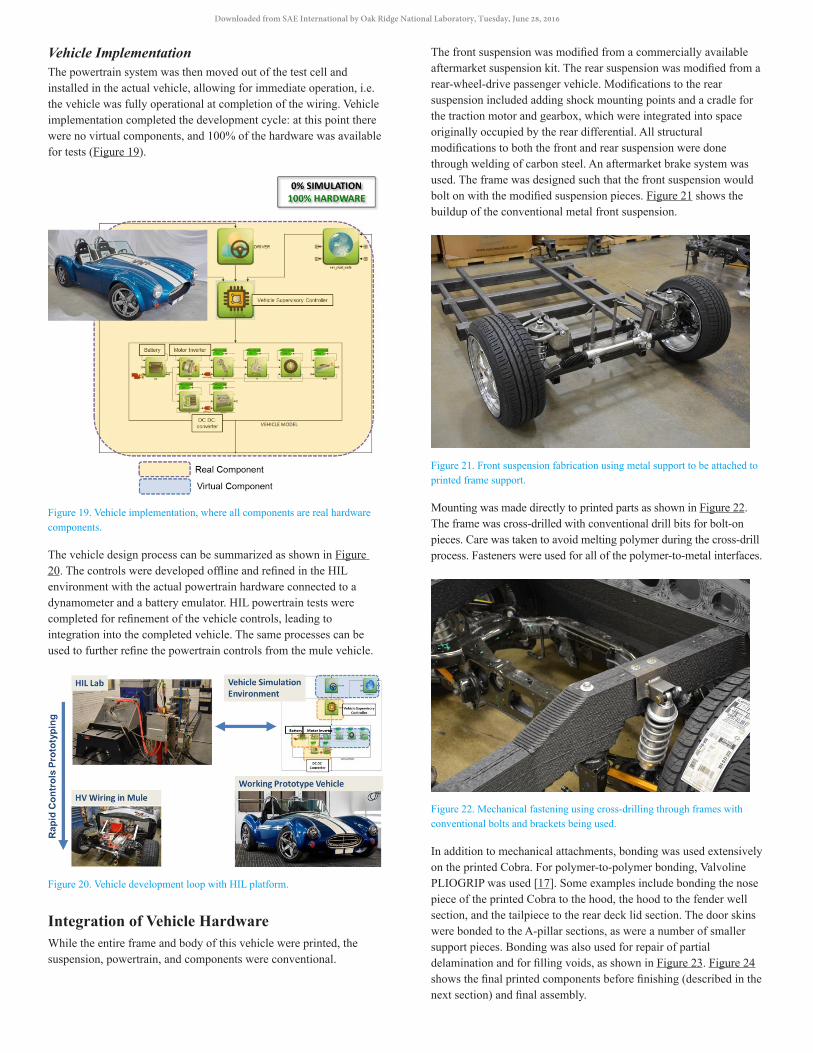
Vehicle ImplementationThe powertrain system was then moved out of the test cell and installed in the actual vehicle, allowing for immediate operation, i.e. the vehicle was fully operational at completion of the wiring. Vehicle implementation completed the development cycle: at this point there were no virtual components, and 100% of the hardware was available for tests (Figure 19).
Figure 19. Vehicle implementation, where all components are real hardware components.
The vehicle design process can be summarized as shown in Figure 20. The controls were developed offline and refined in the HIL environment with the actual powertrain hardware connected to a dynamometer and a battery emulator. HIL powertrain tests were completed for refinement of the vehicle controls, leading to integration into the completed vehicle. The same processes can be used to further refine the powertrain controls from the mule vehicle.
Figure 20. Vehicle development loop with HIL platform.
Integration of Vehicle HardwareWhile the entire frame and body of this vehicle were printed, the suspension, powertrain, and components were conventional.
The front suspension was modified from a commercially available aftermarket suspension kit. The rear suspension was modified from a rear-wheel-drive passenger vehicle. Modifications to the rear suspension included adding shock mounting points and a cradle for the traction motor and gearbox, which were integrated into space originally occupied by the rear differential. All structural modifications to both the front and rear suspension were done through welding of carbon steel. An aftermarket brake system was used. The frame was designed such that the front suspension would bolt on with the modified suspension pieces. Figure 21 shows the buildup of the conventional metal front suspension.
Figure 21. Front suspension fabrication using metal support to be attached to printed frame support.
Mounting was made directly to printed parts as shown in Figure 22. The frame was cross-drilled with conventional drill bits for bolt-on pieces. Care was taken to avoid melting polymer during the cross-drill process. Fasteners were used for all of the polymer-to-metal interfaces.
Figure 22. Mechanical fastening using cross-drilling through frames with conventional bolts and brackets being used.
In addition to mechanical attachments, bonding was used extensively on the printed Cobra. For polymer-to-polymer bonding, Valvoline PLIOGRIP was used [17]. Some examples include bonding the nose piece of the printed Cobra to the hood, the hood to the fender well section, and the tailpiece to the rear deck lid section. The door skins were bonded to the A-pillar sections, as were a number of smaller support pieces. Bonding was also used for repair of partial delamination and for filling voids, as shown in Figure 23. Figure 24 shows the final printed components before finishing (described in the next section) and final assembly.
Downloaded from SAE International by Oak Ridge National Laboratory, Tuesday, June 28, 2016

Figure 23. Bonding and void filling using PLIOGRIP plastic repair.
Figure 24. Printed cobra components before final assembly (not shown are front nose cone or rear cap).
Secondary Machining and Finishing of Carbon Fiber ABS PartsThe printed vehicle would have been completely functional without any additional finishing to the body. Additional surface finishing through machining, sanding, filling, and polishing allowed for the body of the printed vehicle to be painted with an automotive grade paint to near Class A finish. Finishing the vehicle consisted of sanding to remove loose fibers followed by a surface prep and coating to fill the ridges created by the printing process. The carbon fiber-reinforced ABS plastic is a new material, requiring investigation of finishing and painting, and the effects of temperature swings and long-term use are still unknown. Figure 25 shows the body components after finishing and painting.
Figure 25. ABS skins during finishing and painting.
The use of the HIL platform meant that for this case study the powertrain controls were completed in a parallel process to the printing and integration of the vehicle hardware. The next section details the use of the HIL platform in the development of the vehicle powertrain controls through integration into the printed mule.
Vehicle Testing and RefinementThe NTRC also houses a vehicle research laboratory with a 300 hp motor-in-the-middle, two-wheel-drive, 48 in., single roll AC chassis dynamometer. Figure 26 shows the printed Cobra being evaluated on this chassis dynamometer facility. The dynamometer meets the requirements of the EPA Specifications for Large Roll Chassis Dynamometers and can simulate test weights as low as 1,000 lb. equivalent test weight. The ORNL vehicle research laboratory was instrumental in testing the fully assembled vehicle
Due to the accelerated development time frame and experimental nature of the vehicle, road load coefficients were not readily available and coast-down tests could not be performed to measure them in time; therefore, best engineering judgment was used to estimate those coefficients and parameterize the chassis rolls controller accordingly.
Figure 26. Printed Cobra on the ORNL chassis rolls laboratory.
Drive cycles were performed to measure energy consumption. Motor and battery behavior during the US06 cycle performed on the ORNL chassis dynamometer are shown in Figure 27. Chassis dynamometer results for the UDDS, HWFET, New European Drive Cycle (NEDC), and US06 are shown in Table 2.
Figure 27. Motor and battery behavior during US06 cycle performed on the ORNL chassis dynamometer.
Downloaded from SAE International by Oak Ridge National Laboratory, Tuesday, June 28, 2016
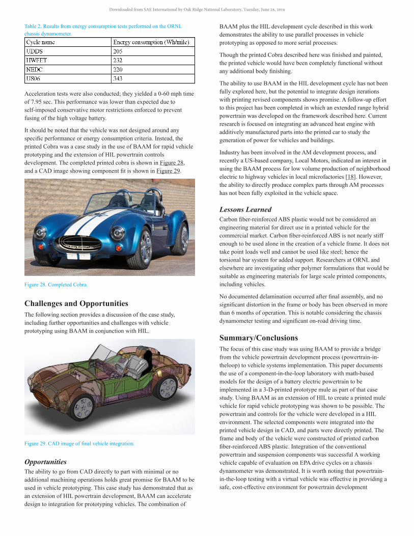
Table 2. Results from energy consumption tests performed on the ORNL chassis dynamometer.
Acceleration tests were also conducted; they yielded a 0-60 mph time of 7.95 sec. This performance was lower than expected due to self-imposed conservative motor restrictions enforced to prevent fusing of the high voltage battery.
It should be noted that the vehicle was not designed around any specific performance or energy consumption criteria. Instead, the printed Cobra was a case study in the use of BAAM for rapid vehicle prototyping and the extension of HIL powertrain controls development. The completed printed cobra is shown in Figure 28, and a CAD image showing component fit is shown in Figure 29.
Figure 28. Completed Cobra.
Challenges and OpportunitiesThe following section provides a discussion of the case study, including further opportunities and challenges with vehicle prototyping using BAAM in conjunction with HIL.
Figure 29. CAD image of final vehicle integration.
OpportunitiesThe ability to go from CAD directly to part with minimal or no additional machining operations holds great promise for BAAM to be used in vehicle prototyping. This case study has demonstrated that as an extension of HIL powertrain development, BAAM can accelerate design to integration for prototyping vehicles. The combination of
BAAM plus the HIL development cycle described in this work demonstrates the ability to use parallel processes in vehicle prototyping as opposed to more serial processes.
Though the printed Cobra described here was finished and painted, the printed vehicle would have been completely functional without any additional body finishing.
The ability to use BAAM in the HIL development cycle has not been fully explored here, but the potential to integrate design iterations with printing revised components shows promise. A follow-up effort to this project has been completed in which an extended range hybrid powertrain was developed on the framework described here. Current research is focused on integrating an advanced heat engine with additively manufactured parts into the printed car to study the generation of power for vehicles and buildings.
Industry has been involved in the AM development process, and recently a US-based company, Local Motors, indicated an interest in using the BAAM process for low volume production of neighborhood electric to highway vehicles in local microfactories [18]. However, the ability to directly produce complex parts through AM processes has not been fully exploited in the vehicle space.
Lessons LearnedCarbon fiber-reinforced ABS plastic would not be considered an engineering material for direct use in a printed vehicle for the commercial market. Carbon fiber-reinforced ABS is not nearly stiff enough to be used alone in the creation of a vehicle frame. It does not take point loads well and cannot be used like steel; hence the torsional bar system for added support. Researchers at ORNL and elsewhere are investigating other polymer formulations that would be suitable as engineering materials for large scale printed components, including vehicles.
No documented delamination occurred after final assembly, and no significant distortion in the frame or body has been observed in more than 6 months of operation. This is notable considering the chassis dynamometer testing and significant on-road driving time.
Summary/ConclusionsThe focus of this case study was using BAAM to provide a bridge from the vehicle powertrain development process (powertrain-in-theloop) to vehicle systems implementation. This paper documents the use of a component-in-the-loop laboratory with math-based models for the design of a battery electric powertrain to be implemented in a 3-D-printed prototype mule as part of that case study. Using BAAM as an extension of HIL to create a printed mule vehicle for rapid vehicle prototyping was shown to be possible. The powertrain and controls for the vehicle were developed in a HIL environment. The selected components were integrated into the printed vehicle design in CAD, and parts were directly printed. The frame and body of the vehicle were constructed of printed carbon fiber-reinforced ABS plastic. Integration of the conventional powertrain and suspension components was successful A working vehicle capable of evaluation on EPA drive cycles on a chassis dynamometer was demonstrated. It is worth noting that powertrain-in-the-loop testing with a virtual vehicle was effective in providing a safe, cost-effective environment for powertrain development
Downloaded from SAE International by Oak Ridge National Laboratory, Tuesday, June 28, 2016

This study did not focus on meeting specific vehicle performance targets or address crashworthiness, vehicle lightweighting, or any other consumer acceptability issues. Studies investigating the crush performance of carbon fiber-reinforced ABS plastic are ongoing at ORNL.
As illustrated in this study, advances in BAAM are showing promise for use in vehicle development. The use of HIL to expand the printed vehicle into a mobile research platform is also very promising. HIL allowed the powertrain integration and testing phase to be conducted in parallel with the chassis build phase, whereas those two phases would otherwise be sequential.
References1. Erickson, G., Heath, M., Woods, B., Dolan, D. et al., "Design
and Manufacture of Titanium Formula SAE Uprights using Laser-Powder-Deposition," SAE Technical Paper 2004-01-3546, 2004, doi:10.4271/2004-01-3546.
2. Reyes Belmonte, M., Copeland, C., Hislop, D., Hopkins, G. et al., "Improving Heat Transfer and Reducing Mass in a Gasoline Piston Using Additive Manufacturing," SAE Technical Paper 2015-01-0505, 2015, doi:10.4271/2015-01-0505.
3. Jay Leno’s 3D Printer Replaces Rusty Old Parts http://www.popularmechanics.com/cars/a4354/4320759/.
4. http://www.e-ci.com/baam/.5. “3-D printed car is as strong as steel, half the weight, and
nearing production,” George, Alexander, 2013 http://www.wired.com/2013/02/3d-printed-car/.
6. “World’s first car made by 3-D printer unveiled in Chicago,” Yahoo News Sept 2014, “http://news.yahoo.com/3d-printed-car-140141613.html#.
7. Love, L., “Utility of Big Area Additive Manufacturing (BAAM) for the Rapid Manufacture of Customized Electric Vehicles,” 2014 ORNL/TM-2014/607, CRADA/NFE-14-04988http://info.ornl.gov/sites/publications/Files/Pub52852.pdf.
8. Talagani, M., et al., “Numerical Simulation of Big Area Additive Manufacturing (3D Printing) of a Full Size Car,” SAMPE Journal, Volume 51, No. 4, July/August 2015
9. Nabi, S., Balike, M., Allen, J., and Rzemien, K., "An Overview of Hardware-In-the-Loop Testing Systems at Visteon," SAE Technical Paper 2004-01-1240, 2004, doi:10.4271/2004-01-1240.
10. Alley, R., Walsh, P., Lambiase, N., Benoy, B. et al., "ESS Design Process Overview and Key Outcomes of Year Two of EcoCAR 2: Plugging in to the Future," SAE Technical Paper 2014-01-1922, 2014, doi:10.4271/2014-01-1922.
11. Wagener, A., Schulte, T., Waeltermann, P., and Schuette, H., "Hardware-in-the-Loop Test Systems for Electric Motors in Advanced Powertrain Applications," SAE Technical Paper 2007-01-0498, 2007, doi:10.4271/2007-01-0498.
12. Love., L., “Cincinnati Big Area Additive Manufacturing (BAAM),” CRADA report ORNL/TM-2015/100, (2015) http://info.ornl.gov/sites/publications/files/Pub54708.pdf.
13. Press Release, “Cincinnati Incorporated and Oak Ridge National Laboratory Advancing Large-Part Additive Manufacturing,” March 2014 http://www.e-ci.com/additive-manufacturing-march.
14. Love, L., Kunc, V., Rios, O., Duty, C., Elliott, A., Post, B., Smith, R., Blue, C., “The importance of carbon fiber to polymer additive manufacturing,” Journal of Materials Research, V. 29 (17), 2014, pp 1893-1898, DOI 10.1557/jmr.2014.212.
15. Tekinalp, H., et al., “Highly oriented carbon fiber-polymer composites via additive manufacturing,” Composites Science and Technology, Volume 105, 10 December 2014, Pages 144-150, ISSN 0266-3538, http://dx.doi.org/10.1016/j.compscitech.2014.10.009.
16. Autonomie website, http://www.autonomie.net/.17. Valvoline PLIOGRIP information website, http://www.
pliogripbyvalvoline.com/plastic-repair/.18. Press Release, “Local Motors Unveils Designs for the World’s
First Production Line of 3D-Printed Cars,” Phoenix, Arizona (July 7, 2015), https://localmotors.com/blog/post/local-motor-sunveils-designs-for-the-worlds-first-production-line-of-3d-printed-cars/1906/.
Contact InformationScott [email protected]
AcknowledgmentsThis work was supported by the US Department of Energy, Office of Energy Efficiency and Renewable Energy, Advanced Manufacturing Office under the management of Mark Johnson. The authors wish to thank their colleagues at the Oak Ridge National Laboratory who worked on this project: Kim Askey, Brett Compton, Brittany Cramer, Claus Daniel, Norberto Domingo, Chad Duty, Shean Huff, Vlastimil Kunc, Nicholas Leak, Karen Nolen, Adrzej Nycz, Burak Ozpineci, Jennifer Palmer, Alex Pawlowski, Matt Salas, Larry Seiber, Jimmy Wade, and Randy Wiles,. The authors would also like to acknowledge the support of the industry partners who helped make the project possible, including Cincinnati Incorporated, GKN, and New Eagle. Special thanks to Rick Spears and Robert Springfield of Tru-Design for collaboration on finishing and transporting the printed Cobra. Special thanks to VJ Ewing at ORNL for technical editing of this manuscript.
DisclaimerThis manuscript has been authored by UT-Battelle, LLC under Contract No. DE-AC05-00OR22725 with the U.S. Department of Energy. The United States Government retains and the publisher, by accepting the article for publication, acknowledges that the United States Government retains a nonexclusive, paid-up, irrevocable, world-wide license to publish or reproduce the published form of this manuscript, or allow others to do so, for United States Government purposes. The Department of Energy will provide public access to these results of federally sponsored research in accordance with the DOE Public Access Plan (http://energy.gov/downloads/doe-public-access-plan).
Downloaded from SAE International by Oak Ridge National Laboratory, Tuesday, June 28, 2016

The Engineering Meetings Board has approved this paper for publication. It has successfully completed SAE’s peer review process under the supervision of the session organizer. The process requires a minimum of three (3) reviews by industry experts.
All rights reserved. No part of this publication may be reproduced, stored in a retrieval system, or transmitted, in any form or by any means, electronic, mechanical, photocopying, recording, or otherwise, without the prior written permission of SAE International.
Positions and opinions advanced in this paper are those of the author(s) and not necessarily those of SAE International. The author is solely responsible for the content of the paper.
ISSN 0148-7191
http://papers.sae.org/2016-01-0328
Downloaded from SAE International by Oak Ridge National Laboratory, Tuesday, June 28, 2016