big-ip® cgnat: implementations - techdocs.f5.com · deploying a carrier grade nat overview: the...
TRANSCRIPT

BIG-IP® CGNAT: Implementations
Version 11.6


Table of Contents
Deploying a Carrier Grade NAT.................................................................................................7
Overview: The carrier-grade NAT (CGNAT) module..........................................................7
About ALG Profiles..................................................................................................8
About CGNAT translation address persistence and inbound connections..............8
About IPv6 prefixes.................................................................................................9
About IPv4 prefixes.................................................................................................9
Creating an LSN pool..............................................................................................9
Configuring an ALG profile....................................................................................10
Configuring a CGNAT iRule..................................................................................10
Creating a virtual server for an LSN pool..............................................................11
Creating a CGNAT tunnel......................................................................................11
Using NAT64 to Map IPv6 Addresses to IPv4 Destinations..................................................13
Overview: NAT64.............................................................................................................13
NAT64 example.....................................................................................................13
Creating a NAT64 LSN pool..................................................................................14
Creating a NAT64 virtual server for an LSN pool..................................................14
Configuring an ALG profile....................................................................................15
Configuring a CGNAT iRule..................................................................................15
Using NAT44 to Translate IPv4 Addresses.............................................................................17
Overview: NAT44.............................................................................................................17
About CGNAT hairpinning.....................................................................................17
Creating an LSN pool............................................................................................18
Creating a virtual server for an LSN pool..............................................................18
Configuring an ALG profile....................................................................................19
Configuring a CGNAT iRule..................................................................................19
Using DS-Lite with CGNAT.......................................................................................................21
Overview: DS-Lite Configuration on BIG-IP systems.......................................................21
About CGNAT hairpinning.....................................................................................22
Creating a DS-Lite tunnel on the BIG-IP device as an AFTR device....................22
Assigning a self IP address to an AFTR device....................................................23
Configuring CGNAT for DS-Lite.............................................................................23
Verifying traffic statistics for a DS-Lite tunnel........................................................24
Using CGNAT Translation Modes............................................................................................25
Overview: Using NAPT address translation mode...........................................................25
3
Table of Contents

NAPT log examples...............................................................................................25
Creating a NAPT LSN pool...................................................................................26
Creating a VLAN for NAT......................................................................................27
Creating a NAT64 virtual server for an LSN pool..................................................28
Overview: Using PBA mode to reduce CGNAT logging...................................................28
About PBA address translation mode...................................................................29
About configuring PBA mode with route domains.................................................29
PBA log examples.................................................................................................30
Creating a PBA LSN pool......................................................................................33
Creating a VLAN for NAT......................................................................................33
Creating a virtual server for an LSN pool..............................................................34
Overview: Deterministic address translation mode..........................................................35
Creating a deterministic LSN pool.........................................................................36
Creating a VLAN for NAT......................................................................................36
Creating a virtual server for an LSN pool..............................................................37
Overview: The DNAT utility..............................................................................................38
DNAT utility example commands...........................................................................38
Downloading the DNAT utility external tool...........................................................39
Using the DNAT utility external tool for reverse mappings....................................39
Using DNAT utility to look up deterministic NAT mappings on the BIG-IP
system..............................................................................................................40
Overview: PCP client address translation........................................................................41
Creating a PCP profile...........................................................................................41
Configuring an LSN pool with a PCP profile.........................................................41
Using ALG Profiles...................................................................................................................43
Overview: Using the FTP ALG Profile to Transfer Files...................................................43
About the FTP profile............................................................................................43
Creating an LSN pool............................................................................................45
Creating an FTP profile.........................................................................................45
Configuring a CGNAT iRule..................................................................................46
Creating a virtual server using an FTP ALG profile...............................................46
Creating an FTP ALG logging profile....................................................................47
Configuring an FTP ALG profile............................................................................47
Overview: Using the SIP ALG Profile for Multimedia Sessions........................................48
About the SIP ALG profile.....................................................................................48
Creating an LSN pool............................................................................................49
Creating a SIP profile............................................................................................50
Creating a virtual server using a SIP ALG profile..................................................51
Creating an empty LSN pool.................................................................................52
Creating a virtual server using a SIP ALG profile and empty LSN pool................52
Creating an SIP ALG logging profile.....................................................................53
Configuring an SIP ALG profile.............................................................................54
Overview: Using the RTSP ALG Profile to Stream Media................................................54
4
Table of Contents

About the RTSP ALG profile.................................................................................55
Creating an LSN pool............................................................................................56
Creating an RTSP profile......................................................................................56
Configuring a CGNAT iRule..................................................................................57
Creating a virtual server using an RTSP ALG profile............................................57
Creating an RTSP ALG logging profile..................................................................58
Configuring an RTSP ALG profile.........................................................................58
Overview: Using the PPTP ALG profile to create a VPN tunnel......................................59
About the PPTP ALG profile..................................................................................59
PPTP profile log example......................................................................................60
Creating an LSN pool............................................................................................61
Creating a PPTP profile.........................................................................................62
Adding a static route to manage GRE traffic.........................................................62
Creating a virtual server using a PPTP ALG profile..............................................63
Using CGNAT Logging and Subscriber Traceability.............................................................65
Overview: Configuring local logging for CGNAT..............................................................65
Creating a formatted local log destination for CGNAT...........................................65
Creating a publisher to send log messages to the local Syslog database ...........66
Configuring an LSN pool with a local Syslog log publisher...................................66
Overview: Configuring remote high-speed logging for CGNAT........................................66
Creating a pool of remote logging servers............................................................67
Creating a remote high-speed log destination.......................................................68
Creating a formatted remote high-speed log destination......................................68
Creating a publisher .............................................................................................69
Creating an LSN logging profile............................................................................69
Configuring an LSN pool ......................................................................................70
Overview: Configuring IPFIX logging for CGNAT.............................................................71
Assembling a pool of IPFIX collectors...................................................................72
Creating an IPFIX log destination..........................................................................73
Creating a publisher .............................................................................................73
Creating an LSN logging profile............................................................................74
Configuring an LSN pool ......................................................................................75
Deploying Stateless Network Address Translation...............................................................77
Overview: 6rd configuration on BIG-IP systems..............................................................77
Task summary..................................................................................................................78
Using a profile to define a 6rd domain...................................................................78
Configuring a BIG-IP system as a border relay (BR) device.................................78
Creating a forwarding virtual server for a tunnel...................................................79
Assigning a self IP address to an IP tunnel endpoint............................................79
Routing traffic through a 6rd tunnel interface........................................................80
Overview: MAP configuration on BIG-IP systems............................................................80
About Mapping of Address and Port (MAP).....................................................................81
5
Table of Contents
About Mapping of Address and Port with Translation (MAP-T).............................81
About Mapping of Address and Port with Encapsulation (MAP)...........................81
Task summary..................................................................................................................82
Using a profile to define a MAP domain................................................................83
Configuring a tunnel for Mapping Address and Port.............................................83
Creating a forwarding virtual server for IPv4 traffic...............................................83
Creating a forwarding virtual server for IPv6 traffic...............................................84
Assigning a self IP address to a MAP tunnel endpoint..........................................84
Viewing MAP tunnel statistics...............................................................................85
IPFIX Templates for CGNAT Events........................................................................................87
Overview: IPFIX logging templates..................................................................................87
IPFIX information elements for CGNAT events................................................................87
IANA-Defined IPFIX information elements............................................................87
IPFIX enterprise information elements..................................................................88
Individual IPFIX templates for each event........................................................................88
NAT44 session create – outbound variant.............................................................89
NAT44 session delete – outbound variant.............................................................89
NAT44 session create – inbound variant...............................................................90
NAT44 session delete – inbound variant...............................................................91
NAT44 translation failed........................................................................................92
NAT44 quota exceeded.........................................................................................92
NAT44 port block allocated or released.................................................................93
NAT64 session create – outbound variant.............................................................93
NAT64 session delete – outbound variant.............................................................94
NAT64 session create – inbound variant...............................................................95
NAT64 session delete – inbound variant...............................................................95
NAT64 translation failed........................................................................................96
NAT64 quota exceeded.........................................................................................97
NAT64 port block allocated or released.................................................................97
DS-Lite session create – outbound variant...........................................................98
DS-Lite session delete – outbound variant............................................................98
DS-Lite session create – inbound variant..............................................................99
DS-Lite session delete – inbound variant............................................................100
DS-Lite translation failed.....................................................................................101
DS-Lite quota exceeded......................................................................................101
DS-Lite port block allocated or released.............................................................102
Legal Notices and Acknowledgments..................................................................................103
Legal Notices.................................................................................................................103
Acknowledgments..........................................................................................................104
6
Table of Contents

Deploying a Carrier Grade NAT
Overview: The carrier-grade NAT (CGNAT) module
The carrier-grade network address translation (CGNAT) module on the BIG-IP® system supports largegroups of translation addresses using large-scale NAT (LSN) pools and grouping of address-translation-relatedoptions in an ALG profile, which can be assigned to multiple virtual servers. It also has the ability to matchvirtual servers based on client address to destination addresses and ports. Other characteristics of the CGNATmodule are listed here.
Note: CGNAT is NAT only. If you want to deploy DNS services, you need a BIG-IP GTM™ license.
Translation address persistence
The CGNAT module can assign the same external (translation) address to all connections originated by thesame internal client. For example, providing endpoint-independent address mapping.
Automatic external inbound connection handling
CGNAT can accept inbound external connections to active translation address/port combinations to facilitateendpoint-independent filtering as described in section 5 of RFC 4787. This is also known as a full-coneNAT.
More efficient logging
CGNAT supports log messages that map external addresses and ports back to internal clients for bothtroubleshooting and compliance with law enforcement/legal constraints.
Network address and port translation
Network address and port translation (NAPT) mode provides standard address and port translation allowingmultiple clients in a private network to access remote networks using the single IP address assigned to theirrouter.
Deterministic assignment of translation addresses
Deterministic mode is an option used to assign translation address, and is port-based on the client address/portand destination address/port. It uses reversible mapping to reduce logging, while maintaining the ability fortranslated IP address to be discovered for troubleshooting and compliance with regulations. Deterministicmode also provides an option to configure backup-members.
Port block allocation of translation addresses
Port block allocation (PBA) mode is an option that reduces logging, by logging only the allocation andrelease of a block of ports. When a subscriber sends a translation request, the BIG-IP system services therequest from a block of ports that is assigned to a single IP address, and only logs the allocation and releaseof that block of ports. The BIG-IP system applies subsequent requests from the service provider to thatblock of ports until all ports are used.
Licensing
Designed for service providers, the CGNAT module is offered as a stand-alone license or as an add-onlicense for Local Traffic Manager™ (LTM®) and Policy Enforcement Manager™ (PEM).
Task summaryCreating an LSN poolConfiguring an ALG profileConfiguring a CGNAT iRuleCreating a virtual server for an LSN poolCreating a CGNAT tunnel
About ALG Profiles
Application Layer Gateway (ALG) profiles provide the CGNAT with protocol and service functionalitythat modifies the necessary application protocol header and payload, thus allowing these protocols toseamlessly traverse the NAT. FTP, RTSP, SIP, and PPTP profiles are supported with ALG profiles, andadded to the CGNAT configuration as needed.
An FTP, RTSP, or SIP profile can use an Automap, NAPT, DNAT, or PBA address translation mode whenproviding necessary logging.
About CGNAT translation address persistence and inbound connections
The BIG-IP® system enables you to manage RFC-defined behavior for translation address persistence andinbound connections.
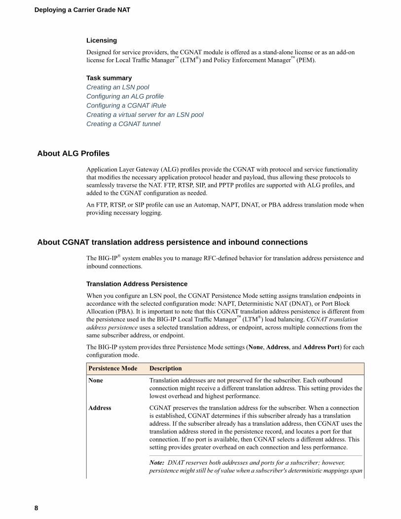
Translation Address Persistence
When you configure an LSN pool, the CGNAT Persistence Mode setting assigns translation endpoints inaccordance with the selected configuration mode: NAPT, Deterministic NAT (DNAT), or Port BlockAllocation (PBA). It is important to note that this CGNAT translation address persistence is different fromthe persistence used in the BIG-IP Local Traffic Manager™ (LTM®) load balancing. CGNAT translationaddress persistence uses a selected translation address, or endpoint, across multiple connections from thesame subscriber address, or endpoint.
The BIG-IP system provides three Persistence Mode settings (None, Address, and Address Port) for eachconfiguration mode.
DescriptionPersistence Mode
Translation addresses are not preserved for the subscriber. Each outboundconnection might receive a different translation address. This setting provides thelowest overhead and highest performance.
None
CGNAT preserves the translation address for the subscriber. When a connectionis established, CGNAT determines if this subscriber already has a translation
Address
address. If the subscriber already has a translation address, then CGNAT uses thetranslation address stored in the persistence record, and locates a port for thatconnection. If no port is available, then CGNAT selects a different address. Thissetting provides greater overhead on each connection and less performance.
Note: DNAT reserves both addresses and ports for a subscriber; however,persistence might still be of value when a subscriber's deterministic mappings span
8
Deploying a Carrier Grade NAT

DescriptionPersistence Mode
two translation addresses. In this instance, persistence prefers the same addresseach time.
CGNAT preserves the translation address and port of the subscriber's connection,so that the endpoint can be reused on subsequent connections. This setting provides
Address Port
Endpoint Independent Mapping (EIM) behavior. Additionally, like the Addresssetting for Persistence Mode, this setting provides greater overhead on eachconnection and less performance.
Inbound Connections
The Inbound Connections setting determines whether the Large Scale NAT (LSN) allows connections tobe established inbound to the LSN subscriber or client. This setting provides greater overhead, including alookup on inbound entries for each connection to prevent endpoint overloading, and a reduction in the useof the translation space.
When you disable inbound connections, the BIG-IP system provides greater efficiency in address spaceutilization by allowing endpoint overloading, where two different subscribers can use the same translationaddress and port, as long as each subscriber connects to a different host.
When you enable inbound connections, the BIG-IP system restricts the use of a translation address and portto a single subscriber, and ensures that only one subscriber address and port uses a translation endpoint.
Note: Because DNAT reserves addresses and ports for a subscriber, no endpoint overloading betweensubscribers occurs, but a single subscriber's traffic can leverage overloading. Inbound connections restrictthis behavior. For DNAT, increased restriction from inbound connections might occur when fewer portsper subscriber are available. With inbound connections enabled, the ratio of subscriber ports to translationendpoints for a subscriber is 1:1.
About IPv6 prefixes
IPv6 128-bit addresses include a network prefix in the leftmost fields, and subnet in the remaining fields.For example, an IPv6 address of 2001:0db8:0000:0000:0000:0000:0000:0000 with a 32-bit prefixequates to a network of 2001:0db8, written as 2001:db8::/32. A network written as 2001:db8::/32omits leading zeros in four-digit groups, uses :: to indicate collapsed zero groups, and uses /32 to indicatethe 32-bit prefix.
About IPv4 prefixes
IPv4 32-bit addresses include a network prefix in the leftmost fields, and a host identifier in the remainingfields. For example, an address of 192.168.1.0/24 includes the prefix of the IPv4 network starting at thegiven address, having 24 bits allocated for the network prefix, and the remaining 8 bits reserved for hostaddressing.
Creating an LSN pool
The CGNAT module must be enabled through the System > Resource Provisioning screen before you cancreate LSN pools.
9
BIG-IP® CGNAT: Implementations

Large Scale NAT (LSN) pools are used by the CGNATmodule to allow efficient configuration of translationprefixes and parameters.
1. On the Main tab, click Carrier Grade NAT > LSN Pools.The LSN Pool List screen opens.
2. Click Create.3. In the Name field, type a unique name.4. In the Configuration area, for theMember List setting, type an address and a prefix length in the
Address/Prefix Length field, and click Add.If your pool uses deterministic mode, ensure that any address ranges you enter as a member do notoverlap another member's prefix address ranges. For example, the address and prefix 10.10.10.0/24overlaps 10.10.10.0/23.
5. Click Finished.
Your LSN pool is now ready, and you can continue to configure your CGNAT.
Configuring an ALG profile
An ALG profile provides the CGNAT module with protocol and service information to make specifiedpacket modifications to the IP and TCP/UDP headers, as well as the payload during translation.
Important: Edit only copies of the included ALG profiles to avoid unwanted propagation of settings toother profiles that use the included profiles as parents.
1. On the Main tab, click Carrier Grade NAT > ALG Profiles.2. In the ALG Profiles menu, click an ALG profile.3. Click Create.
The New Profile screen opens.4. Type a name for the new profile.5. From the Parent Profile list, ensure that the correct parent profile is selected as the new profile.6. Select the Custom check box on the right.7. Configure the profile settings.8. Click Finished to save the new ALG profile.
You now have an ALG profile for use by CGNAT.
Configuring a CGNAT iRule
You create iRules® to automate traffic forwarding for XML content-based routing. When a match occurs,an iRule event is triggered, and the iRule directs the individual request to an LSN pool, a node, or virtualserver.
1. On the Main tab, click Carrier Grade NAT > iRules.The iRule List screen opens.
2. Click Create.3. In the Name field, type a 1 to 31 character name, such as cgn_https_redirect_iRule.4. In the Definition field, type the syntax for the iRule using Tool Command Language (Tcl) syntax.
10
Deploying a Carrier Grade NAT

For complete and detailed information about iRules syntax, see the F5 Networks DevCentral web site(http://devcentral.f5.com).
5. Click Finished.
You now have an iRule to use with a CGNAT virtual server.
Creating a virtual server for an LSN pool
Virtual servers are matched based on source (client) addresses. Define a virtual server that references theCGNAT profile and the LSN pool.
1. On the Main tab, click Carrier Grade NAT > Virtual Servers.The Virtual Server List screen opens.
2. Click the Create button.The New Virtual Server screen opens.
3. In the Name field, type a unique name for the virtual server.4. From the Type list, select Performance (Layer 4).5. For a network, in the Destination Address field, type an IPv4 or IPv6 address in CIDR format to allow
all traffic to be translated.The supported format is address/prefix, where the prefix length is in bits. For example, an IPv4address/prefix is 0.0.0.0/0, and an IPv6 address/prefix is ::/0.
6. In the Service Port field, type * or select * All Ports from the list.7. From theVLAN and Tunnel Traffic list, selectEnabled on. Then, for theVLANs and Tunnels setting,
move the VLAN or VLANs on which you want to allow the virtual servers to share traffic from theAvailable list to the Selected list.
8. For the LSN Pool setting, select the pool that this server will draw on for translation addresses.9. In the Resources area of the screen, for the iRules setting, select the name of the iRule that you want to
assign and using the Move button, move the name from the Available list to the Enabled list.10. Click Finished.
The custom CGNAT virtual server now appears in the CGNAT Virtual Servers list.
Creating a CGNAT tunnel
Many translations use tunneling to move TCP/UDP traffic where the payload is other IP traffic. You cancreate and configure a tunnel for use with an LSN pool.
1. On the Main tab, click Carrier Grade NAT > Tunnels.The Tunnels screen opens.
2. Click Create.The New Tunnel screen opens.
3. In the Name field, type a unique name for the tunnel.4. In the Local Address field, type the IP address of the BIG-IP system.5. From the Remote Address list, retain the default selection, Any.
This entry means that you do not have to specify the IP address of the remote end of the tunnel, whichallows multiple devices to use the same tunnel.
6. Click Finished.
11
BIG-IP® CGNAT: Implementations

Your CGNAT tunnel is ready to use as an egress interface in an LSN Pool.
12
Deploying a Carrier Grade NAT
Using NAT64 to Map IPv6 Addresses to IPv4 Destinations
Overview: NAT64
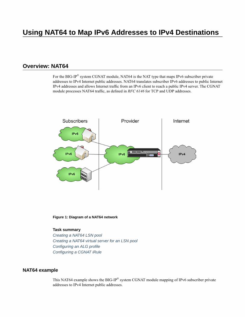
For the BIG-IP® system CGNAT module, NAT64 is the NAT type that maps IPv6 subscriber privateaddresses to IPv4 Internet public addresses. NAT64 translates subscriber IPv6 addresses to public InternetIPv4 addresses and allows Internet traffic from an IPv6 client to reach a public IPv4 server. The CGNATmodule processes NAT64 traffic, as defined in RFC 6146 for TCP and UDP addresses.
Figure 1: Diagram of a NAT64 network
Task summaryCreating a NAT64 LSN poolCreating a NAT64 virtual server for an LSN poolConfiguring an ALG profileConfiguring a CGNAT iRule
NAT64 example
This NAT64 example shows the BIG-IP® system CGNAT module mapping of IPv6 subscriber privateaddresses to IPv4 Internet public addresses.

Figure 2: A NAT64 example configuration
In this example, an IPv6 client initiates a request to the IPv4 server, using a source address of2001:db8::1,1500 and a destination address of 64:ff9b::192.0.2.1,80. The NAT64 on the BIG-IP®
system selects an available port for the IPv4 address 203.0.113.1,2000, and creates a mapping entryfrom 2001:db8::1,1500 to 203.0.113.1,2000. The NAT64 translates the IPv6 header into an IPv4header, including 203.0.113.1,2000 as the source address and 192.0.2.1,80 as the destination address,and sends the translated packet to the IPv4 server.
The IPv4 server responds with a server packet, which includes a destination address of 203.0.113.1,2000and source address of 192.0.2.1,80. Upon receipt of the IPv4 server packet, the NAT64 translates theIPv4 header into an IPv6 header, which includes 2001:db8::1,1500 as the source address, and sends theresponse to the client.
Creating a NAT64 LSN pool
The CGNAT module must be enabled through System > Resource Provisioning before you can configureLSN pools.
Large Scale NAT (LSN) pools are used by the CGNATmodule to allow efficient configuration of translationprefixes and parameters.
1. On the Main tab, click Carrier Grade NAT > LSN Pools.The LSN Pool List screen opens.
2. Click Create.3. In the Name field, type a unique name.4. For theMember List setting, in the Address/Prefix Length field, type an address and a prefix length
and click Add.In a NAT64 implementation, an example of an IPv6 member address and prefix is 64:ff9b::/96.
5. Click Finished.
Your LSN pool is now ready, and you can continue to configure your CGNAT.
Creating a NAT64 virtual server for an LSN pool
Virtual servers are matched based on source (client) addresses. Define a NAT64 virtual server that referencesthe CGNAT profile and the LSN pool.
1. On the Main tab, click Carrier Grade NAT > Virtual Servers.
14
Using NAT64 to Map IPv6 Addresses to IPv4 Destinations
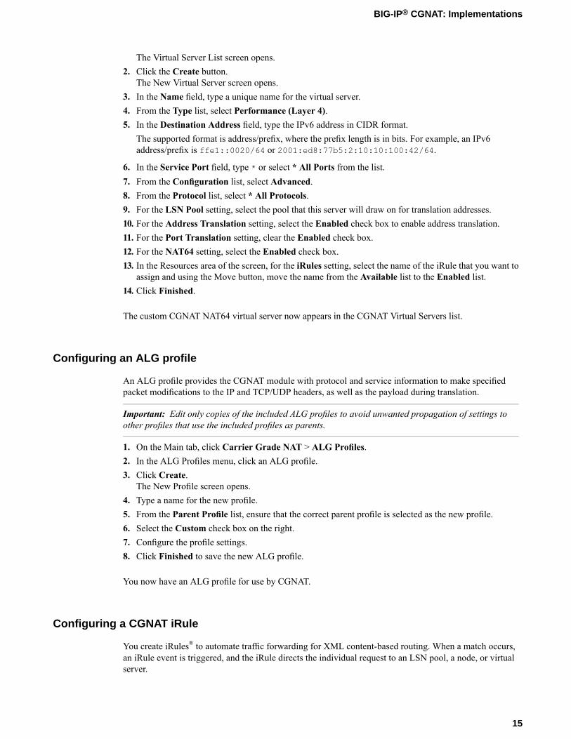
The Virtual Server List screen opens.2. Click the Create button.
The New Virtual Server screen opens.3. In the Name field, type a unique name for the virtual server.4. From the Type list, select Performance (Layer 4).5. In the Destination Address field, type the IPv6 address in CIDR format.
The supported format is address/prefix, where the prefix length is in bits. For example, an IPv6address/prefix is ffe1::0020/64 or 2001:ed8:77b5:2:10:10:100:42/64.
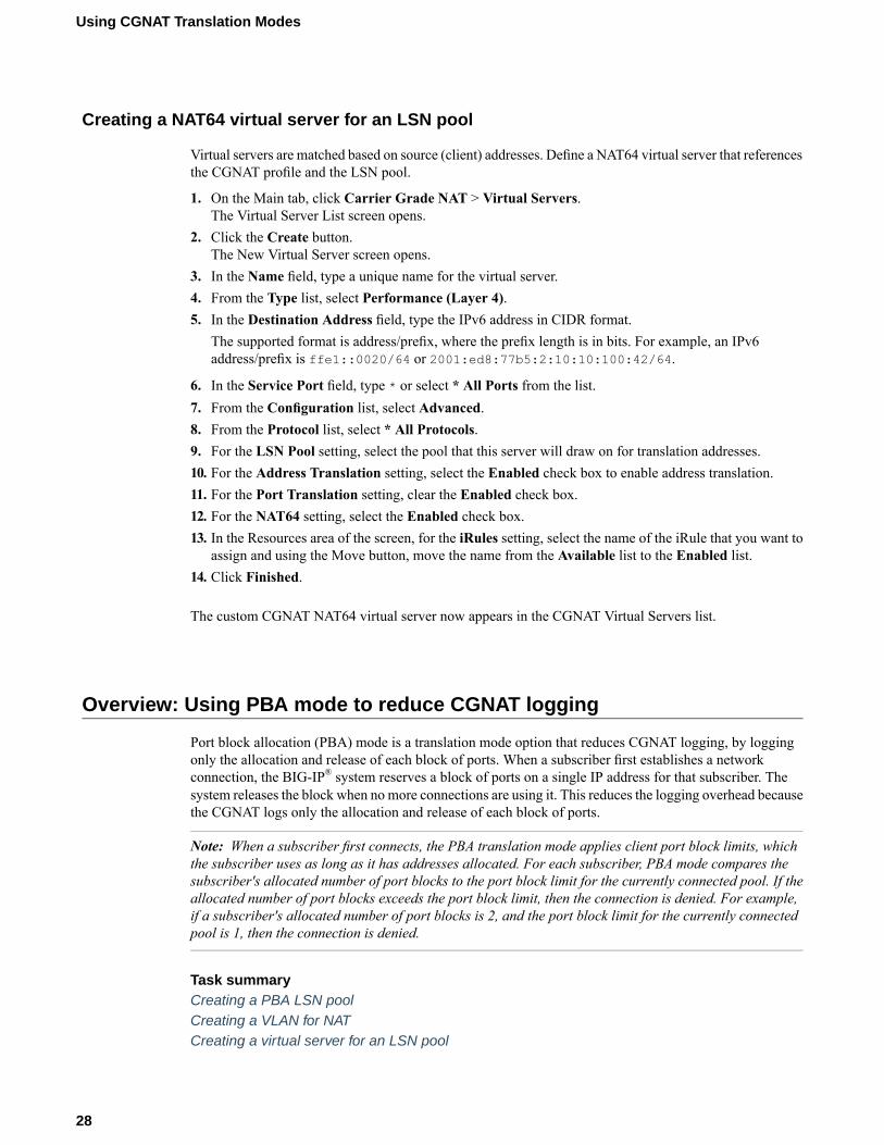
6. In the Service Port field, type * or select * All Ports from the list.7. From the Configuration list, select Advanced.8. From the Protocol list, select * All Protocols.9. For the LSN Pool setting, select the pool that this server will draw on for translation addresses.10. For the Address Translation setting, select the Enabled check box to enable address translation.11. For the Port Translation setting, clear the Enabled check box.12. For the NAT64 setting, select the Enabled check box.13. In the Resources area of the screen, for the iRules setting, select the name of the iRule that you want to
assign and using the Move button, move the name from the Available list to the Enabled list.14. Click Finished.
The custom CGNAT NAT64 virtual server now appears in the CGNAT Virtual Servers list.
Configuring an ALG profile
An ALG profile provides the CGNAT module with protocol and service information to make specifiedpacket modifications to the IP and TCP/UDP headers, as well as the payload during translation.
Important: Edit only copies of the included ALG profiles to avoid unwanted propagation of settings toother profiles that use the included profiles as parents.
1. On the Main tab, click Carrier Grade NAT > ALG Profiles.2. In the ALG Profiles menu, click an ALG profile.3. Click Create.
The New Profile screen opens.4. Type a name for the new profile.5. From the Parent Profile list, ensure that the correct parent profile is selected as the new profile.6. Select the Custom check box on the right.7. Configure the profile settings.8. Click Finished to save the new ALG profile.
You now have an ALG profile for use by CGNAT.
Configuring a CGNAT iRule
You create iRules® to automate traffic forwarding for XML content-based routing. When a match occurs,an iRule event is triggered, and the iRule directs the individual request to an LSN pool, a node, or virtualserver.
15
BIG-IP® CGNAT: Implementations

1. On the Main tab, click Carrier Grade NAT > iRules.The iRule List screen opens.
2. Click Create.3. In the Name field, type a 1 to 31 character name, such as cgn_https_redirect_iRule.4. In the Definition field, type the syntax for the iRule using Tool Command Language (Tcl) syntax.
For complete and detailed information about iRules syntax, see the F5 Networks DevCentral web site(http://devcentral.f5.com).
5. Click Finished.
You now have an iRule to use with a CGNAT virtual server.
16
Using NAT64 to Map IPv6 Addresses to IPv4 Destinations

Using NAT44 to Translate IPv4 Addresses
Overview: NAT44
For the BIG-IP® system CGNAT module, NAT44 is the NAT type that maps IPv4 subscriber privateaddresses to IPv4 Internet public addresses. Translation addresses and ports are set in LSN pools. TheCGNAT module performs NAT44 translations for all IP traffic.
Figure 3: Diagram of a NAT44 network
Task summaryCreating an LSN poolCreating a virtual server for an LSN poolConfiguring an ALG profileConfiguring a CGNAT iRule
About CGNAT hairpinning
An optional feature on the BIG-IP ®system, hairpinning routes traffic from one subscriber's client to anexternal address of another subscriber's server, where both client and server are located in the same subnet.To each subscriber, it appears that the other subscriber's address is on an external host and on a different

subnet. The BIG-IP system can recognize this situation and send, or hairpin, the message back to the originsubnet so that the message can reach its destination.
Note: At present hairpinning works with all BIG-IP CGNAT scenarios except NAT64.
Creating an LSN pool
The CGNAT module must be enabled through the System > Resource Provisioning screen before you cancreate LSN pools.
Large Scale NAT (LSN) pools are used by the CGNATmodule to allow efficient configuration of translationprefixes and parameters.
1. On the Main tab, click Carrier Grade NAT > LSN Pools.The LSN Pool List screen opens.
2. Click Create.3. In the Name field, type a unique name.4. In the Configuration area, for theMember List setting, type an address and a prefix length in the
Address/Prefix Length field, and click Add.If your pool uses deterministic mode, ensure that any address ranges you enter as a member do notoverlap another member's prefix address ranges. For example, the address and prefix 10.10.10.0/24overlaps 10.10.10.0/23.
5. Click Finished.
Your LSN pool is now ready, and you can continue to configure your CGNAT.
Creating a virtual server for an LSN pool
Virtual servers are matched based on source (client) addresses. Define a virtual server that references theCGNAT profile and the LSN pool.
1. On the Main tab, click Carrier Grade NAT > Virtual Servers.The Virtual Server List screen opens.
2. Click the Create button.The New Virtual Server screen opens.
3. In the Name field, type a unique name for the virtual server.4. From the Type list, select Performance (Layer 4).5. For a network, in the Destination Address field, type an IPv4 or IPv6 address in CIDR format to allow
all traffic to be translated.The supported format is address/prefix, where the prefix length is in bits. For example, an IPv4address/prefix is 0.0.0.0/0, and an IPv6 address/prefix is ::/0.
6. In the Service Port field, type * or select * All Ports from the list.7. From theVLAN and Tunnel Traffic list, selectEnabled on. Then, for theVLANs and Tunnels setting,
move the VLAN or VLANs on which you want to allow the virtual servers to share traffic from theAvailable list to the Selected list.
8. For the LSN Pool setting, select the pool that this server will draw on for translation addresses.9. In the Resources area of the screen, for the iRules setting, select the name of the iRule that you want to
assign and using the Move button, move the name from the Available list to the Enabled list.
18
Using NAT44 to Translate IPv4 Addresses
10. Click Finished.
The custom CGNAT virtual server now appears in the CGNAT Virtual Servers list.
Configuring an ALG profile
An ALG profile provides the CGNAT module with protocol and service information to make specifiedpacket modifications to the IP and TCP/UDP headers, as well as the payload during translation.
Important: Edit only copies of the included ALG profiles to avoid unwanted propagation of settings toother profiles that use the included profiles as parents.
1. On the Main tab, click Carrier Grade NAT > ALG Profiles.2. In the ALG Profiles menu, click an ALG profile.3. Click Create.
The New Profile screen opens.4. Type a name for the new profile.5. From the Parent Profile list, ensure that the correct parent profile is selected as the new profile.6. Select the Custom check box on the right.7. Configure the profile settings.8. Click Finished to save the new ALG profile.
You now have an ALG profile for use by CGNAT.
Configuring a CGNAT iRule
You create iRules® to automate traffic forwarding for XML content-based routing. When a match occurs,an iRule event is triggered, and the iRule directs the individual request to an LSN pool, a node, or virtualserver.
1. On the Main tab, click Carrier Grade NAT > iRules.The iRule List screen opens.
2. Click Create.3. In the Name field, type a 1 to 31 character name, such as cgn_https_redirect_iRule.4. In the Definition field, type the syntax for the iRule using Tool Command Language (Tcl) syntax.
For complete and detailed information about iRules syntax, see the F5 Networks DevCentral web site(http://devcentral.f5.com).
5. Click Finished.
You now have an iRule to use with a CGNAT virtual server.
19
BIG-IP® CGNAT: Implementations


Using DS-Lite with CGNAT
Overview: DS-Lite Configuration on BIG-IP systems
As IPv4 addresses are becoming depleted, service providers (DSL, cable, and mobile) face the challengeof supplying IP addresses to new customers. Providing IPv6 addresses alone is often not workable, becausemost of the public Internet still uses only IPv4, and many customer systems do not yet fully support IPv6.The Dual-Stack Lite (DS-Lite) tunneling technology is one solution to this problem. DS-Lite gives serviceproviders the means to migrate to an IPv6 access network without changing end user devices or software.
What is DS-Lite?
DS-Lite is an IPv4-to-IPv6 transition technology, described in RFC 6333, that uses tunneling and networkaddress translation (NAT) to send IPv4 packets over an IPv6 network. This technology makes it possible,for example, for a service provider with an IPv6 backbone to properly route traffic while overlapping IPv4networks.
How does DS-Lite work?
The customer-premises equipment (CPE), known as the B4 (Basic Bridging BroadBand) device, encapsulatesthe IPv4 packets inside IPv6 packets, and sends them to the AFTR (Address Family Transition Router)device. The AFTR device includes carrier-grade NAT (CGNAT), which has a global IPv4 address space.The AFTR device decapsulates the IPv4 traffic and performs address translation, as it sends the traffic tothe external IPv4 network.
How does F5 implement DS-Lite?
On the BIG-IP® system, a DS-Lite tunnel is a variation of IPIP tunnels that uses augmented flow lookupsto route traffic. Augmented flow lookups include the IPv6 address of the tunnel to identify the accuratesource of packets that might have the same IPv4 address. When the BIG-IP device receives an IPv6encapsulated packet, the system terminates the tunnel, decapsulates the packet, and marks it for DS-Lite.When the system re-injects the packet into the IP stack, it performs an augmented flow lookup to properlyroute the response.
Illustration of a DS-Lite deployment
In this example, a service provider transports encapsulated IPv4 traffic over its IPv6 network.

Figure 4: Example of a DS-Lite configuration
Task summaryCreating a DS-Lite tunnel on the BIG-IP device as an AFTR deviceAssigning a self IP address to an AFTR deviceConfiguring CGNAT for DS-LiteVerifying traffic statistics for a DS-Lite tunnel
About CGNAT hairpinning
An optional feature on the BIG-IP ®system, hairpinning routes traffic from one subscriber's client to anexternal address of another subscriber's server, where both client and server are located in the same subnet.To each subscriber, it appears that the other subscriber's address is on an external host and on a differentsubnet. The BIG-IP system can recognize this situation and send, or hairpin, the message back to the originsubnet so that the message can reach its destination.
Note: At present hairpinning works with all BIG-IP CGNAT scenarios except NAT64.
Creating a DS-Lite tunnel on the BIG-IP device as an AFTR device
Before you configure the tunnel, ensure that the BIG-IP® device you are configuring has an IPv6 address.
You can create a DS-Lite (wildcard) tunnel for terminating IPv4-in-IPv6 tunnels to remote B4 devices, andrecycling the IPv4 address space.
1. On the Main tab, click Network > Tunnels > Tunnel List > Create.
22
Using DS-Lite with CGNAT

The New Tunnel screen opens.2. In the Name field, type a unique name for the tunnel.3. From the Encapsulation Type list, select dslite.4. In the Local Address field, type the IPv6 address of the local BIG-IP device.5. For theRemote Address setting, retain the default selection,Any, which indicates a wildcard IP address.6. Click Finished.
You have now created a DS-Lite tunnel that functions as an AFTR (Address Family Translation Router)device.
Assigning a self IP address to an AFTR device
Ensure that you have created a DS-Lite tunnel before you start this task.
Self IP addresses can enable the BIG-IP® system, and other devices on the network, to route applicationtraffic through the associated tunnel.
1. On the Main tab, click Network > Self IPs.2. Click Create.
The New Self IP screen opens.3. In the Name field, type a unique name for the self IP address.4. In the IP Address field, type an IP address.
This IP address is the IPv4 gateway that the B4 devices use to reach the Internet. F5 recommends usingthe IP address space that the IANA has specifically allocated for an AFTR device, for example,192.0.0.1.
5. In the Netmask field, type the full network mask for the specified IP address.
For example, you can type ffff:ffff:ffff:ffff:0000:0000:0000:0000 orffff:ffff:ffff:ffff::.
6. From the VLAN/Tunnel list, select the tunnel with which to associate this self IP address.7. Click Finished.
Configuring CGNAT for DS-Lite
Before starting this task, ensure that CGNAT is licensed and the feature module enabled on the BIG-IP®
system, and you have created at least one LSN pool.
When you are configuring DS-Lite, you must set up a forwarding virtual server to provide the Large ScaleNAT (LSN), which is specified by the DS-Lite tunnel as an augmented flow lookup.
1. On the Main tab, click Carrier Grade NAT > Virtual Servers.The Virtual Server List screen opens.
2. Click the Create button.The New Virtual Server screen opens.
3. In the Name field, type a unique name for the virtual server.4. From the Type list, select Performance (Layer 4).5. In the Destination Address field, type 0.0.0.0/0 to translate all IPv4 traffic.6. In the Service Port field, type * or select * All Ports from the list.
23
BIG-IP® CGNAT: Implementations
7. From the Configuration list, select Advanced.8. From the Protocol list, select * All Protocols.9. From the LSN Pool list, select an LSN pool.10. Click Finished.
This virtual server now intercepts traffic leaving the DS-Lite tunnel, provides the LSN address translation,and forwards the traffic to the IPv4 gateway.
Verifying traffic statistics for a DS-Lite tunnel
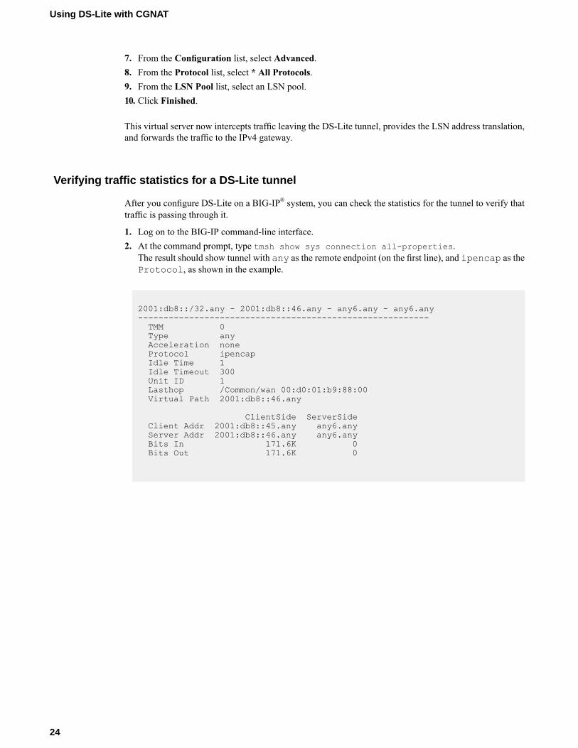
After you configure DS-Lite on a BIG-IP® system, you can check the statistics for the tunnel to verify thattraffic is passing through it.
1. Log on to the BIG-IP command-line interface.2. At the command prompt, type tmsh show sys connection all-properties.
The result should show tunnel with any as the remote endpoint (on the first line), and ipencap as theProtocol, as shown in the example.
2001:db8::/32.any - 2001:db8::46.any - any6.any - any6.any---------------------------------------------------------TMM 0Type anyAcceleration noneProtocol ipencapIdle Time 1Idle Timeout 300Unit ID 1Lasthop /Common/wan 00:d0:01:b9:88:00Virtual Path 2001:db8::46.any
ClientSide ServerSideClient Addr 2001:db8::45.any any6.anyServer Addr 2001:db8::46.any any6.anyBits In 171.6K 0Bits Out 171.6K 0
24
Using DS-Lite with CGNAT

Using CGNAT Translation Modes
Overview: Using NAPT address translation mode
NAPT mode provides standard address and port translation allowing multiple clients in a private networkto access remote networks using the single IP address assigned to their router. For outbound packets, NAPTtranslates the source IP address and source transport identifier. For inbound packets, NAPT translates thedestination IP address, the destination transport identifier, and the IP and transport header checksums. Thismode is beneficial for remote access users.
Task summaryCreating a NAPT LSN poolCreating a VLAN for NATCreating a NAT64 virtual server for an LSN pool
NAPT log examples
The following examples describe typical NAPT log messages
NAT44 example
Mar 27 11:17:39 10.10.10.200 lsn_event="LSN_ADD",cli="10.10.10.1:33950",nat="5.5.5.1:10000"Mar 27 11:17:39 10.10.10.200 "LSN_ADD""10.10.10.1: 33950""5.5.5.1:10000"Mar 27 11:23:17 localhost info tmm[32683]:"LSN_ADD""10.10.10.1:33950""5.5.5.1:10000"Mar 27 11:17:39 10.10.10.200 lsn_event="LSN_DELETE",cli="10.10.10.1:33950",nat="5.5.5.1:10000"Mar 27 11:17:39 10.10.10.200 "LSN_DELETE""10.10.10.1: 33950""5.5.5.1:10000"Mar 27 11:23:17 localhost info tmm[32683]:"LSN_DELETE""10.10.10.1:33950""5.5.5.1:10000"
NAT44 example with route domains
Mar 28 08:34:12 10.10.21.200 lsn_event="LSN_ADD",cli="10.10.10.1%11:59187",nat="5.5.5.1%22:10000"Mar 28 08:34:12 10.10.21.200 "LSN_ADD""10.10.10.1%11: 59187""5.5.5.1%22:10000"Mar 28 08:34:12 10.10.21.200 lsn_event="LSN_DELETE",cli="10.10.10.1%11:59187",nat="5.5.5.1%22:10000"Mar 28 08:34:12 10.10.21.200 "LSN_DELETE""10.10.10.1%11:59187""5.5.5.1%22:10000"
NAT64 example
Mar 27 11:18:20 10.10.10.200 lsn_event="LSN_ADD",cli="2701:1:12:123:1234:432:43:100.39900",nat="5.5.5.1:10000"Mar 27 11:18:20 10.10.10.200 "LSN_ADD""2701:
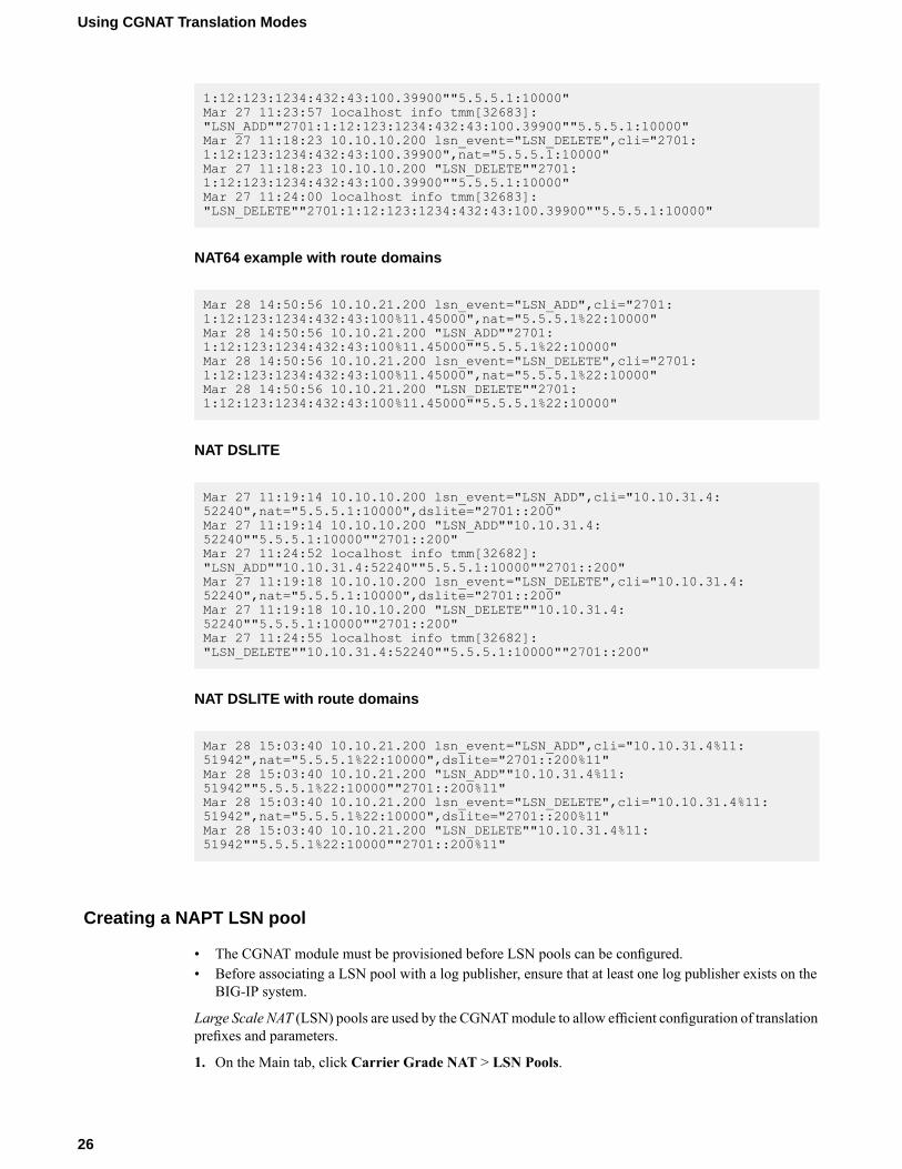
1:12:123:1234:432:43:100.39900""5.5.5.1:10000"Mar 27 11:23:57 localhost info tmm[32683]:"LSN_ADD""2701:1:12:123:1234:432:43:100.39900""5.5.5.1:10000"Mar 27 11:18:23 10.10.10.200 lsn_event="LSN_DELETE",cli="2701:1:12:123:1234:432:43:100.39900",nat="5.5.5.1:10000"Mar 27 11:18:23 10.10.10.200 "LSN_DELETE""2701:1:12:123:1234:432:43:100.39900""5.5.5.1:10000"Mar 27 11:24:00 localhost info tmm[32683]:"LSN_DELETE""2701:1:12:123:1234:432:43:100.39900""5.5.5.1:10000"
NAT64 example with route domains
Mar 28 14:50:56 10.10.21.200 lsn_event="LSN_ADD",cli="2701:1:12:123:1234:432:43:100%11.45000",nat="5.5.5.1%22:10000"Mar 28 14:50:56 10.10.21.200 "LSN_ADD""2701:1:12:123:1234:432:43:100%11.45000""5.5.5.1%22:10000"Mar 28 14:50:56 10.10.21.200 lsn_event="LSN_DELETE",cli="2701:1:12:123:1234:432:43:100%11.45000",nat="5.5.5.1%22:10000"Mar 28 14:50:56 10.10.21.200 "LSN_DELETE""2701:1:12:123:1234:432:43:100%11.45000""5.5.5.1%22:10000"
NAT DSLITE
Mar 27 11:19:14 10.10.10.200 lsn_event="LSN_ADD",cli="10.10.31.4:52240",nat="5.5.5.1:10000",dslite="2701::200"Mar 27 11:19:14 10.10.10.200 "LSN_ADD""10.10.31.4:52240""5.5.5.1:10000""2701::200"Mar 27 11:24:52 localhost info tmm[32682]:"LSN_ADD""10.10.31.4:52240""5.5.5.1:10000""2701::200"Mar 27 11:19:18 10.10.10.200 lsn_event="LSN_DELETE",cli="10.10.31.4:52240",nat="5.5.5.1:10000",dslite="2701::200"Mar 27 11:19:18 10.10.10.200 "LSN_DELETE""10.10.31.4:52240""5.5.5.1:10000""2701::200"Mar 27 11:24:55 localhost info tmm[32682]:"LSN_DELETE""10.10.31.4:52240""5.5.5.1:10000""2701::200"
NAT DSLITE with route domains
Mar 28 15:03:40 10.10.21.200 lsn_event="LSN_ADD",cli="10.10.31.4%11:51942",nat="5.5.5.1%22:10000",dslite="2701::200%11"Mar 28 15:03:40 10.10.21.200 "LSN_ADD""10.10.31.4%11:51942""5.5.5.1%22:10000""2701::200%11"Mar 28 15:03:40 10.10.21.200 lsn_event="LSN_DELETE",cli="10.10.31.4%11:51942",nat="5.5.5.1%22:10000",dslite="2701::200%11"Mar 28 15:03:40 10.10.21.200 "LSN_DELETE""10.10.31.4%11:51942""5.5.5.1%22:10000""2701::200%11"
Creating a NAPT LSN pool
• The CGNAT module must be provisioned before LSN pools can be configured.• Before associating a LSN pool with a log publisher, ensure that at least one log publisher exists on the
BIG-IP system.
Large Scale NAT (LSN) pools are used by the CGNATmodule to allow efficient configuration of translationprefixes and parameters.
1. On the Main tab, click Carrier Grade NAT > LSN Pools.
26
Using CGNAT Translation Modes

The LSN Pool List screen opens.2. Click Create.3. In the Name field, type a unique name.4. In the Description field, type a description.5. Select NAPT for the pool's translationMode.6. Click Finished.
Your NAPT LSN pool is now ready and you can continue to configure your CGNAT.
Creating a VLAN for NAT
VLANs represent a logical collection of hosts that can share network resources, regardless of their physicallocation on the network. You create a VLAN to associate physical interfaces with that VLAN.
1. On the Main tab, click Network > VLANs.The VLAN List screen opens.
2. Click Create.The New VLAN screen opens.
3. In the Name field, type a unique name for the VLAN.4. In the Tag field, type a numeric tag, from 1-4094, for the VLAN, or leave the field blank if you want
the BIG-IP system to automatically assign a VLAN tag.The VLAN tag identifies the traffic from hosts in the associated VLAN.
5. For the Interfaces setting:a) From the Interface list, select an interface number.b) From the Tagging list, select Tagged or Untagged.
Select Tagged when you want traffic for that interface to be tagged with a VLAN ID.c) If you specified a numeric value for theCustomer Tag setting and from theTagging list you selected
Tagged, then from the Tag Mode list, select a value.d) Click Add.e) Repeat these steps for each interface that you want to assign to the VLAN.
6. From the Configuration list, select Advanced.7. If you want the system to verify that the return route to an initial packet is the same VLAN from which
the packet originated, select the Source Check check box.8. In theMTU field, retain the default number of bytes (1500).9. If you want to base redundant-system failover on VLAN-related events, select the Fail-safe check box.10. From the Auto Last Hop list, select a value.11. From the CMP Hash list, select Source if this VLAN is the subscriber side or Destination Address if
this VLAN is the Internet side.12. To enable the DAG Round Robin setting, select the check box.13. Click Finished.
The screen refreshes, and displays the new VLAN in the list.
You now have one of two VLANs for your deterministic or PBANAT. Repeat these steps to create a secondVLAN to act as the destination if the first VLAN is the source or vice versa.
27
BIG-IP® CGNAT: Implementations
Creating a NAT64 virtual server for an LSN pool
Virtual servers are matched based on source (client) addresses. Define a NAT64 virtual server that referencesthe CGNAT profile and the LSN pool.
1. On the Main tab, click Carrier Grade NAT > Virtual Servers.The Virtual Server List screen opens.
2. Click the Create button.The New Virtual Server screen opens.
3. In the Name field, type a unique name for the virtual server.4. From the Type list, select Performance (Layer 4).5. In the Destination Address field, type the IPv6 address in CIDR format.
The supported format is address/prefix, where the prefix length is in bits. For example, an IPv6address/prefix is ffe1::0020/64 or 2001:ed8:77b5:2:10:10:100:42/64.
6. In the Service Port field, type * or select * All Ports from the list.7. From the Configuration list, select Advanced.8. From the Protocol list, select * All Protocols.9. For the LSN Pool setting, select the pool that this server will draw on for translation addresses.10. For the Address Translation setting, select the Enabled check box to enable address translation.11. For the Port Translation setting, clear the Enabled check box.12. For the NAT64 setting, select the Enabled check box.13. In the Resources area of the screen, for the iRules setting, select the name of the iRule that you want to
assign and using the Move button, move the name from the Available list to the Enabled list.14. Click Finished.
The custom CGNAT NAT64 virtual server now appears in the CGNAT Virtual Servers list.
Overview: Using PBA mode to reduce CGNAT logging
Port block allocation (PBA) mode is a translation mode option that reduces CGNAT logging, by loggingonly the allocation and release of each block of ports. When a subscriber first establishes a networkconnection, the BIG-IP® system reserves a block of ports on a single IP address for that subscriber. Thesystem releases the block when no more connections are using it. This reduces the logging overhead becausethe CGNAT logs only the allocation and release of each block of ports.
Note: When a subscriber first connects, the PBA translation mode applies client port block limits, whichthe subscriber uses as long as it has addresses allocated. For each subscriber, PBA mode compares thesubscriber's allocated number of port blocks to the port block limit for the currently connected pool. If theallocated number of port blocks exceeds the port block limit, then the connection is denied. For example,if a subscriber's allocated number of port blocks is 2, and the port block limit for the currently connectedpool is 1, then the connection is denied.
Task summaryCreating a PBA LSN poolCreating a VLAN for NATCreating a virtual server for an LSN pool
28
Using CGNAT Translation Modes
About PBA address translation mode
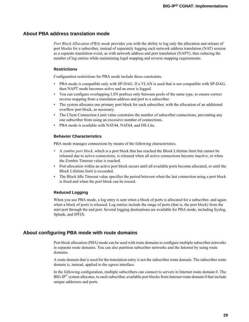
Port Block Allocation (PBA) mode provides you with the ability to log only the allocation and release ofport blocks for a subscriber, instead of separately logging each network address translation (NAT) sessionas a separate translation event, as with network address and port translation (NAPT), thus reducing thenumber of log entries while maintaining legal mapping and reverse mapping requirements.
Restrictions
Configuration restrictions for PBA mode include these constraints.
• PBA mode is compatible only with SP-DAG. If a VLAN is used that is not compatible with SP-DAG,then NAPT mode becomes active and an error is logged.
• You can configure overlapping LSN prefixes only between pools of the same type, to ensure correctreverse mapping from a translation address and port to a subscriber.
• The system allocates one primary port block for each subscriber, with the allocation of an additionaloverflow port block, as necessary.
• The Client Connection Limit value constrains the number of subscriber connections, preventing anyone subscriber from using an excessive number of connections.
• PBA mode is available with NAT44, NAT64, and DS-Lite.
Behavior Characteristics
PBA mode manages connections by means of the following characteristics.
• A zombie port block, which is a port block that has reached the Block Lifetime limit but cannot bereleased due to active connections, is released when all active connections become inactive, or whenthe Zombie Timeout value is reached.
• Port allocation within an active port block occurs until all available ports become allocated, or until theBlock Lifetime limit is exceeded.
• The Block Idle Timeout value specifies the period between when the last connection using a port blockis freed and when the port block can be reused.
Reduced Logging
When you use PBA mode, a log entry is sent when a block of ports is allocated for a subscriber, and againwhen a block of ports is released. Log entries include the range of ports (that is, the port block) from thestart port through the end port. Several logging destinations are available for PBA mode, including Syslog,Splunk, and IPFIX.
About configuring PBA mode with route domains
Port block allocation (PBA) mode can be used with route domains to configure multiple subscriber networksin separate route domains. You can also partition subscriber networks and the Internet by using routedomains.
A route domain that is used for the translation entry is not the subscriber route domain. The subscriber routedomain is, instead, applied to the egress interface.
In the following configuration, multiple subscribers can connect to servers in Internet route domain 0. TheBIG-IP® system allocates, to each subscriber, available port blocks from Internet route domain 0 that includeunique addresses and ports.
29
BIG-IP® CGNAT: Implementations

Figure 5: Multiple subscriber networks connecting to Internet servers in Internet Route Domain 0
In the next configuration, multiple subscribers can connect to servers in respective Internet route domains.The BIG-IP system allocates available port blocks from the respective Internet route domain to thecorresponding subscriber. Allocated port blocks can differ only by route domain, and use identical addressand port ranges; consequently, for this configuration, a service provider must provide a means to distinguishthe connections of different route domains, as necessary.
Figure 6: Multiple subscriber networks connecting to Internet servers in separate Internet routedomains
PBA log examples
Following are some examples of the elements that comprise a typical Port Block Allocation (PBA) modelog entry.
PBA log messages include several elements of interest. The following examples show typical log messages,and the table describes common information types.
NAT44 HSL example
Jul 23 09:33:42 www.siterequest.com "LSN_PB_ALLOCATED""10.10.10.1""5.5.5.9:5555-6666"Jul 23 09:33:42 www.siterequest.com "LSN_PB_RELEASED""10.10.10.1""5.5.5.9:5555-6666"
NAT44 HSL with route domains example
Jul 23 09:33:42 www.siterequest.com"LSN_PB_ALLOCATED""10.10.10.1%55""5.5.5.9%22: 5555-6666"
30
Using CGNAT Translation Modes

Jul 23 09:33:42 www.siterequest.com "LSN_PB_RELEASED""10.10.10.1%55""5.5.5.9%22:5555-6666"
DS-Lite HSL example
Jul 23 10:46:31 www.siterequest.com "LSN_PB_ALLOCATED""2701::200""5.5.5.9:5555-6666"Jul 23 10:46:31 www.siterequest.com "LSN_PB_RELEASED""2701::200""5.5.5.9:5555-6666"
DS-Lite HSL with route domains example
Jul 23 09:36:33 www.siterequest.com "LSN_PB_ALLOCATED""2701::200%11""5.5.5.9%22:5555-6666"Jul 23 09:36:33 www.siterequest.com "LSN_PB_RELEASED""2701::200%11""5.5.5.9%22:5555-6666"
NAT64 HSL example
Jul 23 09:36:33 www.siterequest.com "LSN_PB_ALLOCATED""2701::200""5.5.5.9:5555-6666"Jul 23 09:36:33 www.siterequest.com "LSN_PB_RELEASED""2701::200"5.5.5.9:5555-6666"
NAT64 HSL with route domains example
Jul 23 09:36:33 www.siterequest.com "LSN_PB_ALLOCATED""2701::200%33""5.5.5.9%22:5555-6666"Jul 23 09:36:33 www.siterequest.com "LSN_PB_RELEASED""2701::200%33""5.5.5.9%22:5555-6666"
NAT44 Splunk example
Jul 23 10:56:13 www.siterequest.comlsn_event="LSN_PB_ALLOCATED",lsn_client="10.10.10.1",lsn_pb="5.5.5.9: 5555-6666"Jul 23 10:56:13 www.siterequest.comlsn_event="LSN_PB_RELEASED",lsn_client="10.10.10.1",lsn_pb="5.5.5.9: 5555-6666"
NAT44 Splunk with route domains example
Jul 23 10:56:13 www.siterequest.comlsn_event="LSN_PB_ALLOCATED",lsn_client="10.10.10.1%55",lsn_pb="5.5.5.9%22:5555-6666"Jul 23 10:56:13 www.siterequest.comlsn_event="LSN_PB_RELEASED",lsn_client="10.10.10.1%55",lsn_pb="5.5.5.9%22:5555-6666"
DS-Lite Splunk example
Jul 23 10:57:08 www.siterequest.comlsn_event="LSN_PB_ALLOCATED",lsn_dslite_client="2701:
31
BIG-IP® CGNAT: Implementations

:200",lsn_pb="5.5.5.9:5555-6666"Jul 23 10:57:08 www.siterequest.comlsn_event="LSN_PB_RELEASED",lsn_dslite_client="2701::200",lsn_pb="5.5.5.9:5555-6666"
DS-Lite Splunk with route domains example
Jul 23 10:57:08 www.siterequest.comlsn_event="LSN_PB_ALLOCATED",lsn_dslite_client="2701::200%11",lsn_pb="5.5.5.9%22:5555-6666"Jul 23 10:57:08 www.siterequest.comlsn_event="LSN_PB_RELEASED",lsn_dslite_client="2701::200%11",lsn_pb="5.5.5.9%22:5555-6666"
NAT64 Splunk example
Jul 23 10:57:08 www.siterequest.comlsn_event="LSN_PB_ALLOCATED",lsn_client="2701: :200",lsn_pb="5.5.5.9:5555-6666"Jul 23 10:57:08 www.siterequest.comlsn_event="LSN_PB_RELEASED",lsn_client="2701: :200",lsn_pb="5.5.5.9:5555-6666"
NAT64 Splunk with route domains example
Jul 23 10:57:08 www.siterequest.comlsn_event="LSN_PB_ALLOCATED",lsn_client="2701::200%33",lsn_pb="5.5.5.9%22:5555-6666"Jul 23 10:57:08 www.siterequest.comlsn_event="LSN_PB_RELEASED",lsn_client="2701::200%33",lsn_pb="5.5.5.9%22:5555-6666"
DescriptionExample ValueInformationType
Specifies the time and date that the systemlogged the event message.
Jul 23 10:57:08Timestamp
Specifies the domain name of the client.www.siterequest.comDomainname
Specifies the allocation or release of the portblock.
lsn_event="LSN_PB_ALLOCATED";lsn_event="LSN_PB_RELEASED"
LSN event
Specifies the address of the client.10.10.10.1;10.10.10.1%55;2701: :200;2701: :200%33;
Clientaddress
lsn_client="10.10.10.1";lsn_client="10.10.10.1%55";lsn_dslite_client="2701: :200";lsn_dslite_client="2701: :200%11"
Specifies the address of the port block.5.5.5.9; 5.5.5.9%22Port blockaddress
Specifies the start of the port range.5555Port rangestart
Specifies the end of the port range.6666Port rangeend
32
Using CGNAT Translation Modes

Creating a PBA LSN pool
• The CGNAT module must be provisioned before LSN pools can be configured.• Before associating a LSN pool with a log publisher, ensure that at least one log publisher exists on the
BIG-IP® system.
You configure Large Scale NAT (LSN) pools for the CGNAT module to use in allowing efficientconfiguration of translation prefixes and parameters.
1. On the Main tab, click Carrier Grade NAT > LSN Pools.The LSN Pool List screen opens.
2. Click Create.3. In the Name field, type a unique name.4. In the Description field, type a description.5. For theMode setting, select PBA for the pool's translation.
Note that PBA mode for DS-lite is same as for NAT44, except that all clients behind the DS-Lite tunnelare managed as one subscriber. Port block limits are in accordance with each DS-lite tunnel.
6. For the Port Block Allocation setting, specify your preferred PBA configuration.a) In the Block Size field, type the number of ports designated for a block.b) In the Block Lifetime field, type the number of seconds before a port block times out.
Note: If you type a timeout other than 0, you can also specify a Zombie Timeout. A Block Lifetimevalue that is less than the Persistence Timeout value minimizes the number of zombie port blocks.The default value of 0 specifies no lifetime limit and indefinite use of the port block.
c) In the Block Idle Timeout field, enter the timeout (in seconds) for after the port block becomes idle.
Note: Typically, you want to use a Block Idle Timeout value less than the Persistence Timeoutvalue, to minimize the number of zombie port blocks.
d) In theClient Block Limit field, type the number of blocks that can be assigned to a single subscriberIP address.
e) In the Zombie Timeout field, type the number of seconds before port block times out.A zombie port block is a timed out port block with one or more active connections. The default valueof 0 specifies no timeout and an indefinite zombie state for the port block, as long as connectionsremain active. A value other than 0 specifies a timeout expiration, upon which existing connectionsare terminated, and the port block is released and returned to the pool.
7. In the Configuration area, for theMember List setting, type an address and a prefix length in theAddress/Prefix Length field, and click Add.
8. Click Finished.
Your PBA LSN pool is now ready, and you can continue to configure your CGNAT.
Creating a VLAN for NAT
VLANs represent a logical collection of hosts that can share network resources, regardless of their physicallocation on the network. You create a VLAN to associate physical interfaces with that VLAN.
1. On the Main tab, click Network > VLANs.
33
BIG-IP® CGNAT: Implementations

The VLAN List screen opens.2. Click Create.
The New VLAN screen opens.3. In the Name field, type a unique name for the VLAN.4. In the Tag field, type a numeric tag, from 1-4094, for the VLAN, or leave the field blank if you want
the BIG-IP system to automatically assign a VLAN tag.The VLAN tag identifies the traffic from hosts in the associated VLAN.
5. For the Interfaces setting:a) From the Interface list, select an interface number.b) From the Tagging list, select Tagged or Untagged.
Select Tagged when you want traffic for that interface to be tagged with a VLAN ID.c) If you specified a numeric value for theCustomer Tag setting and from theTagging list you selected
Tagged, then from the Tag Mode list, select a value.d) Click Add.e) Repeat these steps for each interface that you want to assign to the VLAN.
6. From the Configuration list, select Advanced.7. If you want the system to verify that the return route to an initial packet is the same VLAN from which
the packet originated, select the Source Check check box.8. In theMTU field, retain the default number of bytes (1500).9. If you want to base redundant-system failover on VLAN-related events, select the Fail-safe check box.10. From the Auto Last Hop list, select a value.11. From the CMP Hash list, select Source if this VLAN is the subscriber side or Destination Address if
this VLAN is the Internet side.12. To enable the DAG Round Robin setting, select the check box.13. Click Finished.
The screen refreshes, and displays the new VLAN in the list.
You now have one of two VLANs for your deterministic or PBANAT. Repeat these steps to create a secondVLAN to act as the destination if the first VLAN is the source or vice versa.
Creating a virtual server for an LSN pool
Virtual servers are matched based on source (client) addresses. Define a virtual server that references theCGNAT profile and the LSN pool.
1. On the Main tab, click Carrier Grade NAT > Virtual Servers.The Virtual Server List screen opens.
2. Click the Create button.The New Virtual Server screen opens.
3. In the Name field, type a unique name for the virtual server.4. From the Type list, select Performance (Layer 4).5. For a network, in the Destination Address field, type an IPv4 or IPv6 address in CIDR format to allow
all traffic to be translated.The supported format is address/prefix, where the prefix length is in bits. For example, an IPv4address/prefix is 0.0.0.0/0, and an IPv6 address/prefix is ::/0.
6. In the Service Port field, type * or select * All Ports from the list.
34
Using CGNAT Translation Modes

7. From theVLAN and Tunnel Traffic list, selectEnabled on. Then, for theVLANs and Tunnels setting,move the VLAN or VLANs on which you want to allow the virtual servers to share traffic from theAvailable list to the Selected list.
8. For the LSN Pool setting, select the pool that this server will draw on for translation addresses.9. In the Resources area of the screen, for the iRules setting, select the name of the iRule that you want to
assign and using the Move button, move the name from the Available list to the Enabled list.10. Click Finished.
The custom CGNAT virtual server now appears in the CGNAT Virtual Servers list.
Overview: Deterministic address translation mode
Deterministic address translation mode provides address translation that eliminates logging of every addressmapping, while still allowing internal client address tracking using only an external address and port, anda destination address and port. Reverse mapping allows BIG-IP® CGNAT operators to respond to legalrequests revealing the identity of the originator of a specific communication. A typical example is revealingthe identity of file sharers or P2P network users accused of copyright theft.
Deterministic mode allows unique identification of internal client address based on:
• External address and port (the address and port visible to the destination server)• Destination address and port (the service accessed by the client)• Time
Restrictions
Deterministic mode has these configuration restrictions:
• Only NAT44 can use deterministic mode.• The subscriber (client-side) and Internet (server-side) interfaces (VLANs) must be set either as a source
or destination address in the CMP Hash setting.• The complete set of all internal client addresses that will ever communicate through the CGNAT must
be entered at configuration time.
Note: This means that all virtual servers referring to an LSN pool through deterministic NAT modemust specify the source attribute with a value other than 0.0.0.0/0 or ::/0 (any/0, any6/0).
• Use only the most specific address prefixes covering all customer addresses.• Members of two or more deterministic LSN pools must not overlap; in other words, every external
address used for deterministic mapping must occur in only one LSN pool.• Deterministic mode does not support IPFIX.
Simplified logging
As an alternative to per-connection logging, deterministic modemaps internal addresses to external addressesalgorithmically to calculate the mapping without relying on per-connection logging. Deterministic modesignificantly reduces the logging burden while mapping a subscriber's inside IP address with an outsideInternet address and port.
To decipher mapping generated by LSN pools using deterministic mode, you must use the DNAT utilitythat can be run from the system's tmsh command prompt.
35
BIG-IP® CGNAT: Implementations
Task summaryCreating a deterministic LSN poolCreating a VLAN for NATCreating a virtual server for an LSN pool
Creating a deterministic LSN pool
The CGNAT module must be provisioned before you can configure LSN pools.
Large Scale NAT (LSN) pools are used by the CGNATmodule to allow efficient configuration of translationprefixes and parameters.
1. On the Main tab, click Carrier Grade NAT > LSN Pools.The LSN Pool List screen opens.
2. Click Create.3. In the Name field, type a unique name.4. For theMode setting, select Deterministic for the pool's translation.
Note that deterministic mode does not support DS-lite tunneling or NAT64.
5. In the Configuration area, for theMember List setting, type an address and a prefix length in theAddress/Prefix Length field, and click Add.If your pool uses deterministic mode, ensure that any address ranges you enter as a member do notoverlap another member's prefix address ranges. For example, the address and prefix 10.10.10.0/24overlaps 10.10.10.0/23.
6. For deterministic mode, the Backup Member List must have at least one member, so type an addressin the Address/Prefix Length field and click Add.
7. Click Finished.
Your deterministic LSN pool is now ready, and you can continue to configure your CGNAT.
Creating a VLAN for NAT
VLANs represent a logical collection of hosts that can share network resources, regardless of their physicallocation on the network. You create a VLAN to associate physical interfaces with that VLAN.
1. On the Main tab, click Network > VLANs.The VLAN List screen opens.
2. Click Create.The New VLAN screen opens.
3. In the Name field, type a unique name for the VLAN.4. In the Tag field, type a numeric tag, from 1-4094, for the VLAN, or leave the field blank if you want
the BIG-IP system to automatically assign a VLAN tag.The VLAN tag identifies the traffic from hosts in the associated VLAN.
5. For the Interfaces setting:a) From the Interface list, select an interface number.b) From the Tagging list, select Tagged or Untagged.
Select Tagged when you want traffic for that interface to be tagged with a VLAN ID.
36
Using CGNAT Translation Modes
c) If you specified a numeric value for theCustomer Tag setting and from theTagging list you selectedTagged, then from the Tag Mode list, select a value.
d) Click Add.e) Repeat these steps for each interface that you want to assign to the VLAN.
6. From the Configuration list, select Advanced.7. If you want the system to verify that the return route to an initial packet is the same VLAN from which
the packet originated, select the Source Check check box.8. In theMTU field, retain the default number of bytes (1500).9. If you want to base redundant-system failover on VLAN-related events, select the Fail-safe check box.10. From the Auto Last Hop list, select a value.11. From the CMP Hash list, select Source if this VLAN is the subscriber side or Destination Address if
this VLAN is the Internet side.12. To enable the DAG Round Robin setting, select the check box.13. Click Finished.
The screen refreshes, and displays the new VLAN in the list.
You now have one of two VLANs for your deterministic or PBANAT. Repeat these steps to create a secondVLAN to act as the destination if the first VLAN is the source or vice versa.
Creating a virtual server for an LSN pool
Virtual servers are matched based on source (client) addresses. Define a virtual server that references theCGNAT profile and the LSN pool.
1. On the Main tab, click Carrier Grade NAT > Virtual Servers.The Virtual Server List screen opens.
2. Click the Create button.The New Virtual Server screen opens.
3. In the Name field, type a unique name for the virtual server.4. From the Type list, select Performance (Layer 4).5. For a network, in the Destination Address field, type an IPv4 or IPv6 address in CIDR format to allow
all traffic to be translated.The supported format is address/prefix, where the prefix length is in bits. For example, an IPv4address/prefix is 0.0.0.0/0, and an IPv6 address/prefix is ::/0.
6. In the Service Port field, type * or select * All Ports from the list.7. From theVLAN and Tunnel Traffic list, selectEnabled on. Then, for theVLANs and Tunnels setting,
move the VLAN or VLANs on which you want to allow the virtual servers to share traffic from theAvailable list to the Selected list.
8. For the LSN Pool setting, select the pool that this server will draw on for translation addresses.9. In the Resources area of the screen, for the iRules setting, select the name of the iRule that you want to
assign and using the Move button, move the name from the Available list to the Enabled list.10. Click Finished.
The custom CGNAT virtual server now appears in the CGNAT Virtual Servers list.
37
BIG-IP® CGNAT: Implementations

Overview: The DNAT utility
BIG-IP® deterministic NAT (DNAT) mode allows conservation of log storage for service providers bymapping subscribers to public translation addresses and ports algorithmically so that very little data needsto be stored in logs. TheDNAT utility (dnatutil) is necessary for identifying subscribers through calculationof reverse source address and port mapping of deterministic-mode LSN pools, by using the states stored inthe log files.
It can interpret logs from version 11.4.0 and later, correctly reverse mapping subscribers or forward mappingpossible end-points of the subscriber. DNAT, as of version 11.5 of the BIG-IP system, supports multiplelog destinations including, LTM®, Remote Syslog, and Splunk. The DNAT utility can parse logs from anysupported DNAT log destination.
The DNAT utility binary can be run either on the BIG-IP system or on any supported Linux host. The DNATutility package currently supports CentOS 64 and Ubuntu 64 for deployment on Linux systems to supportreverse mappings on archived logs. The package is available from the F5® Downloads site(http://support.f5.com/kb/en-us.html).
Task summaryDownloading the DNAT utility external toolUsing the DNAT utility external tool for reverse mappingsUsing DNAT utility to look up deterministic NAT mappings on the BIG-IP system
DNAT utility example commands
This list provides examples of the syntax used in commands for dnatutil.
ResponseCommand
Shows a list of translation address/port pairs thatmight be used for a subscriber at 10.0.0.1, using theDNAT states contained in /var/log/ltm.
dnatutil 10.0.0.1 --action forward
Performs a reverse mapping back to the subscriberaddress for the connection from
dnatutil 173.240.102.139:5678
173.240.102.139:5678, using the DNAT statescontained in /var/log/ltm.
Performs a reverse mapping back to the subscriberaddress for the connection from
dnatutil --start_time ’2012-09-2706:30:00’ --end_time ’2012-09-2712:10:00’ 173.240.102.139:5678 173.240.102.139:5678, but only shows the subscriber
addresses that used the translation within thespecified time range.
Performs a reverse mapping back to the subscriberaddress for the connection from
dnatutil --start_time ’2012-09-2706:30:00’ --end_time ’2012-09-27
173.240.102.139:5678, showing the subscriber12:10:00’ --file ltmlog-21102013173.240.102.139:5678 addresses that used the translation within the
specified time range, and using the DNAT statescontained in /var/log/test.
Shows summary information, using the DNAT statescontained in /var/log/test.
dnatutil --file /var/log/test
38
Using CGNAT Translation Modes

ResponseCommand
Shows summary information, using the DNAT stateswithin the specified time range.
dnatutil --action summary --start_time’2012-09-27 06:30:00’ --end_time’2012-09-27 12:10:00’
Shows a list of possible subscriber addresses for theprovided client address.
dnatutil --action reverse_addr 1.2.3.4
Provides version information for the utility.dnatutil --help | grep DAG_ID
Downloading the DNAT utility external tool
The deterministic NAT (DNAT) reverse mapping tool can run independently from the BIG-IP® system.Follow these steps to download the dnatutil RPM or Debian file from the F5® Downloads site.
1. Access the F5 Downloads site at http://downloads.f5.com.2. From the Downloads Overview page, click Find a Download.
The Select a Product Line page displays.3. Under Product Line, click the BIG-IP software branch BIG-IP v11.x.4. Select BIG-IP version 11.5 from the drop-down menu.
The system selects the most recent version of software, by default.
5. From the Name column, select dnatutil.A Software Terms and Conditions page appears.
6. Read the End User Software License Agreement (EULA) and either accept the license by clicking IAccept, or cancel the process by clicking Cancel.If you accept the EULA, the Select a Download page appears with a table detailing the file name, productdescription, and size of the file. You should see three files:
• dnatutil.rpm• dnatutil.deb• readme.txt
7. Select the file you would like to download.
Now that you have downloaded the DNAT utility RPM/Debian package, you can now use dnatutil forforward and reverse mappings.
Using the DNAT utility external tool for reverse mappings
To discover the subscriber address, you need to have at least the NAT/public address you would like totranslate. It is preferable to have the date, time, and NAT/public address, port, and the archived logs withthe state information you wish to use.
Deterministic NATs (DNATs) can reduce total log file size but require use of the DNAT utility (dnatutil)to decipher the mapping. With dnatutil, you can calculate forward end-points and reverse client addressand port mapping of an LSN pool using deterministic mode based on the state stored in the specified logfile.
1. Download the BIG-IP® version 11.x RPM or Debian file from the F5® Downloads web site(https://downloads.f5.com) to a preferred location.
2. Using the command line, type install -Uvh <rpm> to install the RPM file.
39
BIG-IP® CGNAT: Implementations

3. Type dnatutil with the date, time, NAT/public address, and port that you want to translate.
dnatutil –-file /var/log/messages --start_time "2013-10-02 15:21:12"–-end_time "2013-10-02 15:22:42" 1.1.1.1:1234
4. Press enter.If the BIG-IP platform is located in a different time zone than the receiving log server, messages mightnot be correctly interpreted. TZ is an environmental variable that specifies the timezone. If not specified,the local timezone is used.
# dnatutil --file ltm 1.1.7.1:1025From (1365014711): 2013-04-03 18:45:11 GMTReverse mapping for ::,80 -> 1.1.7.1,1025Using cmp-hash 'dst-ip' and TMM 1:10.10.10.11
The log entry will show the source prefix, destination prefix (public address), and the subscriber IPaddress for the time range.
You now have the basic details for deciphering deterministic log files using the DNAT utility.
Using DNAT utility to look up deterministic NAT mappings on the BIG-IP system
You should have a knowledge of navigating in tmsh before using the DNAT utility (dnatutil). Fordetailed information about navigating in tmsh, see the Traffic Management Shell (tmsh) Reference Guide.
Deterministic NATs can reduce total log file size but require use of the dnatutil (available in tmsh) todecipher the mapping. With the dnatutil, you can calculate forward and reverse source address and portmapping of an LSN pool using deterministic mode based on the state stored in the specified TMM log file.
1. Use an SSH tool to access the BIG-IP® system from the command line.2. At the command line, type: tmsh.
This starts tmsh in interactive shell mode and displays the prompt: (tmos)#.3. Note: If you do not provide a file and you are on a BIG-IP system, it will default to the LTM® log.
To show a list of translation address/port pairs used for a subscriber at 10.0.0.1:4321 connecting to65.61.115.222:80, using the deterministic NAT states contained in /var/log/ltm, type thecommand:run util dnat --file /var/log/ltm --client_addr 10.0.0.1 --client_port4321 --server_addr 65.61.115.222 --action forward
Replace these example addresses with your actual client and server.This displays a list of the address/port pairs.
4. To calculate a reverse mapping back to the subscriber address for the connection between173.240.102.139:5678 and 65.61.115.222:80, using the DNAT states contained in /var/log/ltm.1,type the command: run util dnat --file /var/log/ltm.1 --server_addr 65.61.115.222--client_addr 173.240.102.139 --client_port 5678 --action reverseThis displays the reverse mapping.
5. For more information about the DNAT utility, type the command: help util dnat at the tmsh prompt.The help file for the DNAT utility is displayed.
You now have the basic details for deciphering deterministic log files using the DNAT utility in tmsh.
40
Using CGNAT Translation Modes

Overview: PCP client address translation
Port Control Protocol (PCP) clients can request specific NAT/CGNAT mappings for themselves and/or forthird-party devices. This allows the PCP clients to set their own public-side IP addresses (also calledtranslation addresses) in a network that uses CGNAT. In cases where the BIG-IP® system assigns a translationaddress or port other than the one requested, the client is at least aware of their assigned address or port.
You apply a PCP profile to a Large Scale NAT (LSN) pool of translation addresses. A client that uses theLSN pool can also send PCP requests to the BIG-IP system to request a particular address/port from thepool. RFC 6887 defines PCP.
Note: The port block allocation (PBA) translation mode is not supported for PCP client address translation.
Task summaryCreating a PCP profileConfiguring an LSN pool with a PCP profile
Creating a PCP profile
Someone must license the CGNAT module through System > License, and enable it through System >Resource Provisioning before you can create a PCP profile.
A PCP profile defines limitations for PCP-client requests.
1. On the Main tab, click Carrier Grade NAT > PCP Profiles > +.The New PCP Profile screen opens.
2. In the Name field, type a unique name.3. You can accept the defaults in this profile, or you can select the check box next to any setting that you
want to change.The online help describes each field.
4. Click Finished.
Your PCP profile is now ready to be used in one or more LSN pools.
Configuring an LSN pool with a PCP profile
An LSN Pool is a group of addresses and ports to be used as translation addresses by a virtual server's clients.If one of those clients sends a PCP request (for example, to map the client's private IP address to a particulartranslation address), the LSN pool's PCP profile determines the ranges and limits allowed for the request.
You assign a PCP profile to an LSN pool in the pool's configuration screen. You also designate the IPaddress and/or DS-Lite tunnel to which the virtual server's clients can send their PCP requests.
1. On the Main tab, click Carrier Grade NAT > LSN Pools.The LSN Pool List screen opens.
2. Click the name of an LSN pool.3. From the PCP Profile list, select a pre-created PCP profile.
If you have not yet created a customized profile, you can use the default PCP profile pcp.
41
BIG-IP® CGNAT: Implementations

The other two PCP-related settings become active.4. Type a self IP address or a DS-Lite tunnel where the virtual server's clients can send their PCP requests.
You can use either field:
• Use the PCP Server IP list to select one of the existing self IP addresses on the system, or• Use the PCP DS-LITE Tunnel Name - IPv6 list to select an existing DS-Lite tunnel
The virtual server's clients can send PCP requests to the self-IP address or through the DS-Lite tunnelyou selected.
After you perform this task, any virtual server with this LSN pool can support PCP. The virtual server'sclients can send PCP MAP requests to the address or tunnel you specified here.
No client can use this PCP configuration unless the LSN pool is assigned to at least one virtual server. Goto Carrier Grade NAT > Virtual Servers > Virtual Server List for a list of servers. Look for the LSNpool's name in the LSN Pool column. Confirm that at least one virtual server uses this LSN pool.
42
Using CGNAT Translation Modes

Using ALG Profiles
Overview: Using the FTP ALG Profile to Transfer Files
The File Transfer Protocol (FTP) application layer gateway (ALG) profile enables you to transfer filesbetween a client and server. The FTP ALG profile supports both active and passive modes, where dataconnections are initiated either from an FTP server (active mode) or from a client (passive mode). You cantransfer files using the FTP protocol by configuring an LSN pool, configuring an FTP profile, and thenassigning the LSN pool and FTP profile to a virtual server. The FTP protocol is described in RFC 959.
Task summaryCreating an LSN poolCreating an FTP profileConfiguring a CGNAT iRuleCreating a virtual server using an FTP ALG profileCreating an FTP ALG logging profileConfiguring an FTP ALG profile
About the FTP profile
The File Transfer Protocol (FTP) profile enables you to transfer files between a client and server, usingFTP connections over TCP. The FTP application layer gateway (ALG) supports the FTP protocol's activeand passive modes, where data connections are initiated either from an FTP server (active mode) or froma client (passive mode).
You can configure the FTP profile settings, as needed, to ensure compatibility between IPv4 and IPv6 clientsand servers, to enable the FTP data channel to inherit the TCP profile used by the FTP control channel, andto use a port other than the default port (20). Additionally, when used with Application Security Manager™
(ASM™), this profile enables the BIG-IP® system to inspect FTP traffic for security vulnerabilities by usingan FTP security profile.
FTP Control Channels
Once established, the FTP control channel remains open throughout the FTP session. The FTP controlchannel and the FTP data channel must both originate from the same IP address.
FTP Data Channels
In active mode, the FTP server initiates data connections. A client informs the server as to what port theclient is listening on, and the server connects to the client by using that port.

Figure 7: An example FTP active mode configuration
In this example, an LSN pool is configured with a translation IP address and prefix length of 10.33.1.0/24.The virtual server is configured with an FTP control port using a wildcard address and a specific port:0.0.0.0:21. The FTP data port is configured to use port 20. The configured translation mode uses thevalues of the respective port range.
Port rangeTranslation mode
2000-3000NAPT
2000-2200DNAT
2000-2150PBA
In passive mode, the FTP client initiates data connections. The FTP server informs the client as to what portthe server is listening on, and the client connects to the server by using that port.
Figure 8: An example FTP passive mode configuration
In this example, an LSN pool is configured with a translation IP address and prefix length of 10.33.1.0/24.The virtual server is configured with an FTP control port using a wildcard address and a specific port:0.0.0.0:21. The FTP data port is configured to use port 20. In this example, the configured translationmode uses the values of the respective port range.
Port rangeTranslation mode
2000-3000NAPT
44
Using ALG Profiles

Port rangeTranslation mode
2000-2200DNAT
2000-2150PBA
Creating an LSN pool
The CGNAT module must be enabled through the System > Resource Provisioning screen before you cancreate LSN pools.
Large Scale NAT (LSN) pools are used by the CGNATmodule to allow efficient configuration of translationprefixes and parameters.
1. On the Main tab, click Carrier Grade NAT > LSN Pools.The LSN Pool List screen opens.
2. Click Create.3. In the Name field, type a unique name.4. In the Configuration area, for theMember List setting, type an address and a prefix length in the
Address/Prefix Length field, and click Add.If your pool uses deterministic mode, ensure that any address ranges you enter as a member do notoverlap another member's prefix address ranges. For example, the address and prefix 10.10.10.0/24overlaps 10.10.10.0/23.
5. Click Finished.
Your LSN pool is now ready, and you can continue to configure your CGNAT.
Creating an FTP profile
You can configure a file transfer protocol (FTP) profile on the BIG-IP® system that transfers files, eitherin an active or passive mode, and logs related messages.
1. On the Main tab, click Carrier Grade NAT > ALG Profiles > FTP.The FTP screen opens and displays a list of available FTP ALG profiles.
2. Click Create.3. Type a name for the profile.4. From the Parent Profile list, select a parent profile.5. Select the Custom check box.6. Select the Translate Extended check box to ensure compatibility between IPv4 and IPv6 clients and
servers when using the FTP protocol. The default is selected.7. Select the Inherit Parent Profile check box to enable the FTP data channel to inherit the TCP profile
used by the control channel. The default is cleared.
Note: If disabled, the data channel uses FastL4 (BigProto) only.
8. In the Data Port field, type a number for an alternate port. The default value for the FTP data port is20.
9. Click Finished.
45
BIG-IP® CGNAT: Implementations

An FTP profile is configured on the BIG-IP® system that transfers files, either in an active or passive mode,and logs related messages.
Configuring a CGNAT iRule
You create iRules® to automate traffic forwarding for XML content-based routing. When a match occurs,an iRule event is triggered, and the iRule directs the individual request to an LSN pool, a node, or virtualserver.
1. On the Main tab, click Carrier Grade NAT > iRules.The iRule List screen opens.
2. Click Create.3. In the Name field, type a 1 to 31 character name, such as cgn_https_redirect_iRule.4. In the Definition field, type the syntax for the iRule using Tool Command Language (Tcl) syntax.
For complete and detailed information about iRules syntax, see the F5 Networks DevCentral web site(http://devcentral.f5.com).
5. Click Finished.
You now have an iRule to use with a CGNAT virtual server.
Creating a virtual server using an FTP ALG profile
Virtual servers are matched based on source (client) addresses. Define a virtual server in order to referencean FTP profile and LSN pool.
1. On the Main tab, click Carrier Grade NAT > Virtual Servers.The Virtual Server List screen opens.
2. Click the Create button.The New Virtual Server screen opens.
3. In the Name field, type a unique name for the virtual server.4. From the Type list, retain the default setting Standard.5. In the Destination Address field, type the IP address in CIDR format.
The supported format is address/prefix, where the prefix length is in bits. For example, an IPv4address/prefix is 10.0.0.1 or 10.0.0.0/24, and an IPv6 address/prefix is ffe1::0020/64 or2001:ed8:77b5:2:10:10:100:42/64. When you use an IPv4 address without specifying a prefix,the BIG-IP® system automatically uses a /32 prefix.
Note: The IP address you type must be available and not in the loopback network.
6. In the Service Port field, type 21 or select FTP from the list.7. From the Protocol list, select TCP.8. From the Protocol Profile (Client) list, select a predefined or user-defined TCP profile.9. From the Protocol Profile (Server) list, select a predefined or user-defined TCP profile.10. From the FTP Profile list, select an FTP ALG profile for the virtual server to use.11. For the LSN Pool setting, select the pool that this server will draw on for addresses.12. Locate the Resources area of the screen; for the Related iRules setting, from the Available list, select
the name of the iRule that you want to assign and move the name to the Enabled list.
46
Using ALG Profiles
This setting applies to virtual servers that reference a profile for a data channel protocol, such as FTPor RTSP.
13. Click Finished.
The custom CGNAT virtual server appears in the CGNAT Virtual Servers list.
Creating an FTP ALG logging profile
You can create an ALG logging profile, and associate it with one or more FTP ALG profiles, to allow youto configure logging options for various events that apply to high-speed logging (HSL) destinations. Alogging profile decreases the need to maintain a number of customized profiles where the events are verysimilar.
1. On the Main tab, click Carrier Grade NAT > Logging Profiles > ALG.The ALG logging profiles screen opens.
2. Click Create.The New ALG Logging Profile screen opens.
3. In the Name field, type a unique name for the logging profile.4. From the Parent Profile list, select a profile from which the new profile inherits properties.5. Select the Custom check box for the Log Settings area.6. For the Log Settings area, select Enabled for the following settings, as necessary.
DescriptionSetting
Generates event log entries at the start of a control channelconnection for an ALG client.
Start Control Channel
Generates event log entries at the end of a control channelconnection for an ALG client.
End Control Channel
Generates event log entries at the start of a data channel connectionfor an ALG client.
Start Data Channel
Generates event log entries at the end of a data channel connectionfor an ALG client.
End Data Channel
Generates event log entries at the start of an inbound connection tothe BIG-IP® system.
Inbound Transaction
7. Click Finished.
Configuring an FTP ALG profile
You can associate an FTP ALG profile with a log publisher and logging profile that the BIG-IP® systemuses to send log messages to a specified destination.
1. On the Main tab, click Carrier Grade NAT > ALG Profiles > FTP.The FTP screen opens and displays a list of available FTP ALG profiles.
2. Click the name of an FTP profile.3. From the Log Publisher list, select the log publisher that the BIG-IP system uses to send log messages
to a specified destination.
47
BIG-IP® CGNAT: Implementations
Important: If you configure a log publisher to use multiple logging destinations, then, by default, alllogging destinations must be available in order to log to each destination. Unless all logging destinationsare available, no logging can occur. If you want to log to the available logging destinations when oneor more destinations become unavailable, you must set the logpublisher.atomic db key to false.If all the remote high-speed log (HSL) destinations are down (unavailable), setting thelogpublisher.atomic db key to false will not work to allow the logs to be written to local-syslog.The logpublisher.atomic db key has no effect on local-syslog.
4. From the Logging Profile list, select the logging profile the BIG-IP system uses to configure loggingoptions for various ALG events.
Note: If you configure a Logging Profile, you must also configure a Log Publisher.
5. Click Finished.
Overview: Using the SIP ALG Profile for Multimedia Sessions
The Session Initiation Protocol (SIP) application layer gateway (ALG) profile enables you to managepeer-to-peer connections through a CGNAT, permitting a client on an external network to initiate andestablish a multimedia session with a user on an internal network. You can enable SIP multimedia sessionsby configuring an LSN pool, configuring a SIP profile, and then assigning the LSN pool and SIP profile toa virtual server. The SIP protocol is described in RFC 3261.
Task summaryCreating an LSN poolCreating a SIP profileCreating a virtual server using a SIP ALG profileCreating an empty LSN poolCreating a virtual server using a SIP ALG profile and empty LSN poolCreating an SIP ALG logging profileConfiguring an SIP ALG profile
About the SIP ALG profile
The Session Initiation Protocol (SIP) profile establishes connections over TCP, UDP, and SCTP througha CGNAT. It creates the connections by establishing flows for multimedia traffic, and by translating IPaddresses included in SIP messages into external IP addresses. As a result, these can be reached by meansof a public network. Once a call is established, the SIP ALG creates flows for multimedia traffic (asdetermined by the advertised address and port combinations on either side of a call), and tears down theflow when the call ends.
You can configure the SIP profile settings, as needed, to provide the following functionality.
• A maximum message size• Closed connection when a BYE transaction completes• Use of SIP dialog information• High-speed logging (HSL) security checking• Association of a SIP virtual server-profile pairing with a SIP proxy functional group
48
Using ALG Profiles
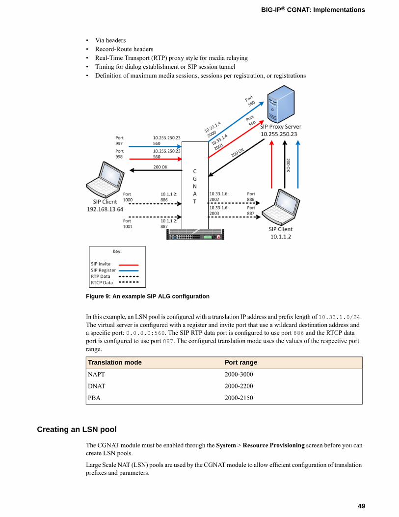
• Via headers• Record-Route headers• Real-Time Transport (RTP) proxy style for media relaying• Timing for dialog establishment or SIP session tunnel• Definition of maximum media sessions, sessions per registration, or registrations
Figure 9: An example SIP ALG configuration
In this example, an LSN pool is configured with a translation IP address and prefix length of 10.33.1.0/24.The virtual server is configured with a register and invite port that use a wildcard destination address anda specific port: 0.0.0.0:560. The SIP RTP data port is configured to use port 886 and the RTCP dataport is configured to use port 887. The configured translation mode uses the values of the respective portrange.
Port rangeTranslation mode
2000-3000NAPT
2000-2200DNAT
2000-2150PBA
Creating an LSN pool
The CGNAT module must be enabled through the System > Resource Provisioning screen before you cancreate LSN pools.
Large Scale NAT (LSN) pools are used by the CGNATmodule to allow efficient configuration of translationprefixes and parameters.
49
BIG-IP® CGNAT: Implementations

1. On the Main tab, click Carrier Grade NAT > LSN Pools.The LSN Pool List screen opens.
2. Click Create.3. In the Name field, type a unique name.4. In the Configuration area, for theMember List setting, type an address and a prefix length in the
Address/Prefix Length field, and click Add.If your pool uses deterministic mode, ensure that any address ranges you enter as a member do notoverlap another member's prefix address ranges. For example, the address and prefix 10.10.10.0/24overlaps 10.10.10.0/23.
5. Click Finished.
Your LSN pool is now ready, and you can continue to configure your CGNAT.
Creating a SIP profile
You can configure a session initiation protocol (SIP) profile on the BIG-IP® system that manages peer-to-peerconnections through a CGNAT.
1. On the Main tab, click Carrier Grade NAT > ALG Profiles > SIP.The SIP screen opens and displays a list of available SIP ALG profiles.
2. Click Create.3. Type a name for the profile.4. From the Parent Profile list, select a parent profile.5. Select the Custom check box.6. In theMaximum Size (Bytes) field, type a number to specify the maximum size, in bytes, for a SIP
message. The default is 65535 bytes.7. Clear the Terminate on BYE check box.
Important: You must clear the Terminate on BYE check box for a TCP or UDP connection when theBIG-IP system functions as a SIP proxy, configuring the inbound SNAT and consolidating multiple callsinto one server-side connection. You should select the Terminate on BYE check box to improveperformance only for a UDP connection if each client call comes from a unique IP address and noinbound SNATs are configured.
8. Select the Dialog Aware check box to gather SIP dialog information, and automatically forward SIPmessages belonging to the known SIP dialog. The default is cleared.
9. Select the Security check box to enable the use of enhanced HSL security checking. The default iscleared.
10. With the Dialog Aware check box selected, in the Community field, type a string to indicate whetherthe SIP virtual server-profile pair belongs to the same SIP proxy functional group.
11. Configure the Insert Via Header settings.a) From the Insert Via Header list, select Enabled to insert a Via header in the forwarded SIP request.
The default is Disabled.b) With the Insert Via Header setting enabled, in theUser Via field type a value that the system inserts
as the top Via header in a SIP REQUEST message.
12. Select the Secure Via Header check box to insert a secure Via header in the forwarded SIP request.The default is cleared.
50
Using ALG Profiles

13. Select the Insert Record-Route Header check box to insert a Record-Route SIP header, which indicatesthe next hop for the following SIP request messages. The default is cleared.
14. Configure the Application Level Gateway settings.a) From the Application Level Gateway list, select Enabled to provide options for defining ALG
settings. The default is Disabled.b) From the RTP Proxy Style list, select Symmetric.c) In the Dialog Establishment Timeout field, type an interval, in seconds, during which the system
attempts to establish a peer-to-peer SIP relationship between two user agents, which facilitatessequencing of messages and proper routing of requests between two user agents. The default is 10.
d) In the Registration Timeout field, type a time, in seconds, that elapses before the SIP registrationprocess expires. The default is 3600.
Note: When configuring a SIP profile for use with Port Block Allocation (PBA), the RegistrationTimeout value must be less than the PBA Block Lifetime value.
e) In the SIP Session Timeout field, type an idle time, in seconds, after which the SIP session timesout. The default is 300.
f) In theMaximumMedia Sessions field, type a maximum number of allowable sessions. The defaultis 6.
g) In theMaximum Sessions Per Registration field, type a maximum number of allowable sessionsper registration. The default is 50.
h) In theMaximum Registrations field, type a maximum number of allowable registrations. Thedefault is 100.
15. Select the SIP Firewall check box to indicate that SIP firewall capability is enabled. The default iscleared.
16. Click Finished.
A SIP profile is configured on the BIG-IP® system that manages peer-to-peer connections through a CGNAT.
Creating a virtual server using a SIP ALG profile
Virtual servers are matched based on source (client) addresses. Here are the steps to define a virtual serverthat references a SIP profile and LSN pool.
1. On the Main tab, click Carrier Grade NAT > Virtual Servers.The Virtual Server List screen opens.
2. Click the Create button.The New Virtual Server screen opens.
3. In the Name field, type a unique name for the virtual server.4. From the Type list, retain the default setting Standard.5. For a network, in the Destination Address field, type an IPv4 or IPv6 address in CIDR format to allow
all traffic to be translated.The supported format is address/prefix, where the prefix length is in bits. For example, an IPv4address/prefix is 0.0.0.0/0, and an IPv6 address/prefix is ::/0.
6. In the Service Port field, type 5060.7. From the Configuration list, select Advanced.8. From the Protocol list, select one of the following:
• UDP
51
BIG-IP® CGNAT: Implementations

• TCP• * All Protocols
9. From the Protocol Profile (Client) list, select a predefined or user-defined profile.10. From the Protocol Profile (Server) list, select a predefined or user-defined profile.11. From the SIP Profile list, select a SIP ALG profile for the virtual server to use.12. For the LSN Pool setting, select the LSN pool that this server uses for addresses.13. From the Source Port list, select Change.14. Click Finished.
The custom CGNAT virtual server appears in the CGNAT Virtual Servers list.
Creating an empty LSN pool
The CGNAT module must be enabled through the System > Resource Provisioning screen before you cancreate LSN pools.
Large Scale NAT (LSN) pools are used by the CGNATmodule to allow efficient configuration of translationprefixes and parameters.
1. On the Main tab, click Carrier Grade NAT > LSN Pools.The LSN Pool List screen opens.
2. Click Create.3. In the Name field, type a unique name.4. From Persistence Mode, select to persist on Address Port.
This is the address mode the CGNAT module uses to track and store connection data.
5. From the Log Publisher list, select the log publisher the BIG-IP system uses to send log messages to aspecified destination.
Important: If you configure a log publisher to use multiple logging destinations, then, by default, alllogging destinations must be available in order to log to each destination. Unless all logging destinationsare available, no logging can occur. If you want to log to the available logging destinations when oneor more destinations become unavailable, you must set the logpublisher.atomic db variable tofalse.
6. Click Finished.
Your empty LSN pool is now ready.
Creating a virtual server using a SIP ALG profile and empty LSN pool
Virtual servers are matched based on source (client) addresses. Here are the steps to define a virtual serverthat references a SIP profile and LSN pool.
1. On the Main tab, click Carrier Grade NAT > Virtual Servers.The Virtual Server List screen opens.
2. Click the Create button.The New Virtual Server screen opens.
3. In the Name field, type a unique name for the virtual server.
52
Using ALG Profiles

4. From the Type list, retain the default setting Standard.5. In the Source field, type 0.0.0.0/0.6. For a host, in the Destination Address field, type an IPv4 or IPv6 address in CIDR format to allow all
traffic to be translated.The supported format is address/prefix, where the prefix length is in bits. For example, an IPv4address/prefix is 0.0.0.0/0, and an IPv6 address/prefix is ::/0.
7. In the Service Port field, type the port number 5060 for the service.8. From the Configuration list, select Advanced.9. From the Protocol list, select one of the following:
• UDP• TCP• * All Protocols
10. From the Protocol Profile (Client) list, select a predefined or user-defined profile.11. From the Protocol Profile (Server) list, select a predefined or user-defined profile.12. From the SIP Profile list, select the same SIP ALG profile for this virtual server to use as the other
virtual server.13. For the LSN Pool setting, select the empty pool that this server will use for addresses.14. Click Finished.
The custom CGNAT virtual server appears in the CGNAT Virtual Servers list.
Creating an SIP ALG logging profile
You can create an ALG logging profile, and associate it with one or more SIP ALG profiles, to allow youto configure logging options for various events that apply to high-speed logging (HSL) destinations. Alogging profile decreases the need to maintain a number of customized profiles where the events are verysimilar.
1. On the Main tab, click Carrier Grade NAT > Logging Profiles > ALG.The ALG logging profiles screen opens.
2. On the Main tab, click Local Traffic > Profiles > Other > ALG Logging.The ALG Logging screen opens.
3. Click Create.The New ALG Logging Profile screen opens.
4. In the Name field, type a unique name for the logging profile.5. From the Parent Profile list, select a profile from which the new profile inherits properties.6. Select the Custom check box for the Log Settings area.7. For the Log Settings area, select Enabled for the following settings, as necessary.
DescriptionSetting
Generates event log entries at the start of a control channelconnection for an ALG client.
Start Control Channel
Generates event log entries at the end of a control channelconnection for an ALG client.
End Control Channel
Generates event log entries at the start of a data channel connectionfor an ALG client.
Start Data Channel
53
BIG-IP® CGNAT: Implementations

DescriptionSetting
Generates event log entries at the end of a data channel connectionfor an ALG client.
End Data Channel
Generates event log entries at the start of an inbound connection tothe BIG-IP® system.
Inbound Transaction
8. Click Finished.
Configuring an SIP ALG profile
You can associate an SIP ALG profile with a log publisher and logging profile that the BIG-IP® systemuses to send log messages to a specified destination.
1. On the Main tab, click Carrier Grade NAT > ALG Profiles > SIP.The SIP screen opens and displays a list of available SIP ALG profiles.
2. Click the name of an SIP profile.3. From the Log Publisher list, select the log publisher that the BIG-IP system uses to send log messages
to a specified destination.
Important: If you configure a log publisher to use multiple logging destinations, then, by default, alllogging destinations must be available in order to log to each destination. Unless all logging destinationsare available, no logging can occur. If you want to log to the available logging destinations when oneor more destinations become unavailable, you must set the logpublisher.atomic db key to false.If all the remote high-speed log (HSL) destinations are down (unavailable), setting thelogpublisher.atomic db key to false will not work to allow the logs to be written to local-syslog.The logpublisher.atomic db key has no effect on local-syslog.
4. From the Logging Profile list, select the logging profile the BIG-IP system uses to configure loggingoptions for various ALG events.
Note: If you configure a Logging Profile, you must also configure a Log Publisher.
5. Click Finished.
Overview: Using the RTSP ALG Profile to Stream Media
The Real Time Streaming Protocol (RTSP) application layer gateway (ALG) profile enables you to establishstreaming multimedia sessions between a client and a server. You can stream multimedia sessions byconfiguring an LSN pool, configuring an RTSP profile, and then assigning the LSN pool and RTSP profileto a virtual server. The RTSP protocol is described in RFC 2326.
Task summaryCreating an LSN poolCreating an RTSP profileConfiguring a CGNAT iRuleCreating a virtual server using an RTSP ALG profile
54
Using ALG Profiles
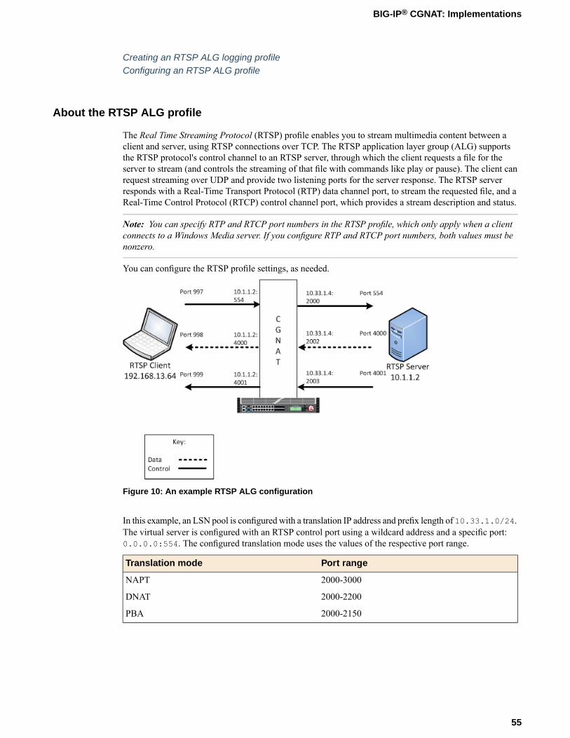
Creating an RTSP ALG logging profileConfiguring an RTSP ALG profile
About the RTSP ALG profile
The Real Time Streaming Protocol (RTSP) profile enables you to stream multimedia content between aclient and server, using RTSP connections over TCP. The RTSP application layer group (ALG) supportsthe RTSP protocol's control channel to an RTSP server, through which the client requests a file for theserver to stream (and controls the streaming of that file with commands like play or pause). The client canrequest streaming over UDP and provide two listening ports for the server response. The RTSP serverresponds with a Real-Time Transport Protocol (RTP) data channel port, to stream the requested file, and aReal-Time Control Protocol (RTCP) control channel port, which provides a stream description and status.
Note: You can specify RTP and RTCP port numbers in the RTSP profile, which only apply when a clientconnects to a Windows Media server. If you configure RTP and RTCP port numbers, both values must benonzero.
You can configure the RTSP profile settings, as needed.
Figure 10: An example RTSP ALG configuration
In this example, an LSN pool is configured with a translation IP address and prefix length of 10.33.1.0/24.The virtual server is configured with an RTSP control port using a wildcard address and a specific port:0.0.0.0:554. The configured translation mode uses the values of the respective port range.
Port rangeTranslation mode
2000-3000NAPT
2000-2200DNAT
2000-2150PBA
55
BIG-IP® CGNAT: Implementations

Creating an LSN pool
The CGNAT module must be enabled through the System > Resource Provisioning screen before you cancreate LSN pools.
Large Scale NAT (LSN) pools are used by the CGNATmodule to allow efficient configuration of translationprefixes and parameters.
1. On the Main tab, click Carrier Grade NAT > LSN Pools.The LSN Pool List screen opens.
2. Click Create.3. In the Name field, type a unique name.4. In the Configuration area, for theMember List setting, type an address and a prefix length in the
Address/Prefix Length field, and click Add.If your pool uses deterministic mode, ensure that any address ranges you enter as a member do notoverlap another member's prefix address ranges. For example, the address and prefix 10.10.10.0/24overlaps 10.10.10.0/23.
5. Click Finished.
Your LSN pool is now ready, and you can continue to configure your CGNAT.
Creating an RTSP profile
You can configure a real time streaming protocol (RTSP) profile on the BIG-IP® system that streamsmultimedia content between a client and server.
1. On the Main tab, click Carrier Grade NAT > ALG Profiles > RTSP.The RTSP screen opens and displays a list of available RTSP ALG profiles.
2. Click Create.3. Type a name for the profile.4. From the Parent Profile list, select a parent profile.5. Select the Custom check box.6. In the RTP Port field, type the port number that a Microsoft Media Services server uses. The default
is 0.
Note: You can specify Real-Time Transport Protocol (RTP) and Real-Time Control Protocol (RTCP)port numbers in the RTSP profile, which only apply when a client connects to a Windows Media® server.If you configure RTP and RTCP port numbers, both values must be nonzero.
7. In the RTCP Port field, type the port number that a Microsoft Media Services server uses. The defaultis 0.
Note: You can specify Real-Time Transport Protocol (RTP) and Real-Time Control Protocol (RTCP)port numbers in the RTSP profile, which only apply when a client connects to a Windows Media® server.If you configure RTP and RTCP port numbers, both values must be nonzero.
8. Click Finished.
An RTSP profile is configured on the BIG-IP® system that streams multimedia content between a clientand server.
56
Using ALG Profiles

Configuring a CGNAT iRule
You create iRules® to automate traffic forwarding for XML content-based routing. When a match occurs,an iRule event is triggered, and the iRule directs the individual request to an LSN pool, a node, or virtualserver.
1. On the Main tab, click Carrier Grade NAT > iRules.The iRule List screen opens.
2. Click Create.3. In the Name field, type a 1 to 31 character name, such as cgn_https_redirect_iRule.4. In the Definition field, type the syntax for the iRule using Tool Command Language (Tcl) syntax.
For complete and detailed information about iRules syntax, see the F5 Networks DevCentral web site(http://devcentral.f5.com).
5. Click Finished.
You now have an iRule to use with a CGNAT virtual server.
Creating a virtual server using an RTSP ALG profile
Virtual servers are matched based on source (client) addresses. Here are the steps to define a virtual serverthat references an RTSP profile and LSN pool.
1. On the Main tab, click Carrier Grade NAT > Virtual Servers.The Virtual Server List screen opens.
2. Click the Create button.The New Virtual Server screen opens.
3. In the Name field, type a unique name for the virtual server.4. From the Type list, retain the default setting Standard.5. In the Destination Address field, type the IP address in CIDR format.
The supported format is address/prefix, where the prefix length is in bits. For example, an IPv4address/prefix is 10.0.0.1 or 10.0.0.0/24, and an IPv6 address/prefix is ffe1::0020/64 or2001:ed8:77b5:2:10:10:100:42/64. When you use an IPv4 address without specifying a prefix,the BIG-IP® system automatically uses a /32 prefix.
Note: The IP address you type must be available and not in the loopback network.
6. In the Service Port field, type 554 for the service.7. From the Protocol list, select TCP.8. From the Protocol Profile (Client) list, select a predefined or user-defined TCP profile.9. From the Protocol Profile (Server) list, select a predefined or user-defined TCP profile.10. From the RTSP Profile list, select an RISP ALG profile for the virtual server to use.11. For the LSN Pool setting, select the pool that this server will draw on for addresses.12. Locate the Resources area of the screen; for the Related iRules setting, from the Available list, select
the name of the iRule that you want to assign and move the name to the Enabled list.This setting applies to virtual servers that reference a profile for a data channel protocol, such as FTPor RTSP.
13. Click Finished.
57
BIG-IP® CGNAT: Implementations

The custom CGNAT virtual server appears in the CGNAT Virtual Servers list.
Creating an RTSP ALG logging profile
You can create an ALG logging profile, and associate it with one or more RTSP ALG profiles, to allowyou to configure logging options for various events that apply to high-speed logging (HSL) destinations.A logging profile decreases the need to maintain a number of customized profiles where the events are verysimilar.
1. On the Main tab, click Carrier Grade NAT > Logging Profiles > ALG.The ALG logging profiles screen opens.
2. On the Main tab, click Local Traffic > Profiles > Other > ALG Logging.The ALG Logging screen opens.
3. Click Create.The New ALG Logging Profile screen opens.
4. In the Name field, type a unique name for the logging profile.5. From the Parent Profile list, select a profile from which the new profile inherits properties.6. Select the Custom check box for the Log Settings area.7. For the Log Settings area, select Enabled for the following settings, as necessary.
DescriptionSetting
Generates event log entries at the start of a control channelconnection for an ALG client.
Start Control Channel
Generates event log entries at the end of a control channelconnection for an ALG client.
End Control Channel
Generates event log entries at the start of a data channel connectionfor an ALG client.
Start Data Channel
Generates event log entries at the end of a data channel connectionfor an ALG client.
End Data Channel
Generates event log entries at the start of an inbound connection tothe BIG-IP® system.
Inbound Transaction
8. Click Finished.
Configuring an RTSP ALG profile
You can associate an RTSP ALG profile with a log publisher and logging profile that the BIG-IP® systemuses to send log messages to a specified destination.
1. On the Main tab, click Carrier Grade NAT > ALG Profiles > RTSP.The RTSP screen opens and displays a list of available RTSP ALG profiles.
2. Click the name of an RTSP profile.3. From the Log Publisher list, select the log publisher that the BIG-IP system uses to send log messages
to a specified destination.
Important: If you configure a log publisher to use multiple logging destinations, then, by default, alllogging destinations must be available in order to log to each destination. Unless all logging destinationsare available, no logging can occur. If you want to log to the available logging destinations when one
58
Using ALG Profiles

or more destinations become unavailable, you must set the logpublisher.atomic db key to false.If all the remote high-speed log (HSL) destinations are down (unavailable), setting thelogpublisher.atomic db key to false will not work to allow the logs to be written to local-syslog.The logpublisher.atomic db key has no effect on local-syslog.
4. From the Logging Profile list, select the logging profile the BIG-IP system uses to configure loggingoptions for various ALG events.
Note: If you configure a Logging Profile, you must also configure a Log Publisher.
5. Click Finished.
Overview: Using the PPTP ALG profile to create a VPN tunnel
The point-to-point tunneling protocol (PPTP) profile enables you to configure the BIG-IP® system to supporta secure virtual private network (VPN) tunnel that forwards PPTP control and data connections. You cancreate a secure VPN tunnel by configuring a PPTP Profile, and then assigning the PPTP profile to a virtualserver. The PPTP protocol is described in RFC 2637.
Important: You cannot combine or use the PPTP Profile with another profile other than a TCP Profile.The PPTP Profile must be used separately and independently.
Task summaryCreating an LSN poolCreating a PPTP profileAdding a static route to manage GRE trafficCreating a virtual server using a PPTP ALG profile
About the PPTP ALG profile
The point-to-point tunneling protocol (PPTP) profile enables you to configure the BIG-IP® system to supporta secure virtual private network (VPN) tunnel. A PPTP application layer gateway (ALG) forwards PPTPclient (also known as PPTP Access Concentrator [PAC]) control and data connections through the BIG-IPsystem to PPTP servers (also known as PPTP Network Servers [PNSs]), while providing source addresstranslation that allows multiple clients to share a single translation address.
The PPTP profile defines a Transmission Control Protocol (TCP) control connection and a data channelthrough a PPTP Generic Routing Encapsulation (GRE) tunnel, which manages the PPTP tunnels throughCGNAT for NAT44 and DS-Lite, as well as all translation modes, including Network Address PortTranslation (NAPT), Deterministic, and Port Block Allocation (PBA) modes.
PPTP control channels
The BIG-IP system proxies PPTP control channels as normal TCP connections. The PPTP profile translatesoutbound control messages, which contain Call Identification numbers (Call IDs) that match the port thatis selected on the outbound side. Subsequently, for inbound control messages containing translated CallIDs, the BIG-IP system restores the original client Call ID. You can use a packet tracer to observe thistranslation on the subscriber side or on the Internet side. You can also use iRules® to evaluate and manageany headers in the PPTP control channel.
59
BIG-IP® CGNAT: Implementations

PPTP GRE data channels
The BIG-IP system manages the translation for PPTP GRE data channels in a manner similar to that ofcontrol channels. The BIG-IP system replaces the translated Call ID from the Key field of the GRE headerwith the inbound client's Call ID. You can use a packet tracer to observe this translation, as well.
Important: A PPTP ALG configuration requires a route to the PPTP client in order to return GRE trafficto the PPTP client. A route to the PPTP client is required because GRE traffic (in both directions) isforwarded based on standard IP routing, unlike TCP control connections, which are automatically routedbecause of the default auto-lasthop=enabled setting.
Figure 11: An example PPTP ALG configuration
Log messages
The PPTP profile enables you to configure Log Settings, specifically the Publisher Name setting, whichlogs the name of the log publisher, and the Include Destination IP setting, which logs the host IP addressof the PPTP server, for each call establishment, call failure, and call teardown.
Note: If a client, for example, a personal computer (PC) or mobile phone, attempts to create a secondconcurrent call, then an error message is logged and sent to the client.
PPTP profile log example
This topic includes examples of the elements that comprise a typical log entry.
Description of PPTP log messages
PPTP log messages include several elements of interest. The following examples describe typical logmessages.
"Mar 1 18:46:11:PPTP CALL-REQUEST id;0 from;10.10.10.1 to;20.20.20.1nat;30.30.30.1 ext-id;32456""Mar 1 18:46:11:PPTP CALL-START id;0 from;10.10.10.1 to;20.20.20.1nat;30.30.30.1 ext-id;32456""Mar 1 18:46:11:PPTP CALL-END id;0 reason;0 from;10.10.10.1 to;20.20.20.1nat;30.30.30.1 ext-id;32456"
60
Using ALG Profiles

DescriptionExample ValueInformation Type
The time and date that the system logged the event message.Mar 1 18:46:11Timestamp
The logged transformation mode.PPTPTransformation mode
The type of command that is logged.CALL-REQUEST,CALL-START,CALL-END
Command
The client Call ID received from a subscriber.id;0Client Call ID
The IP address of the client that initiated the connection.from;10.10.10.1Client IP address
A code number that correlates the reason for terminatingthe connection. The following reason codes apply:
reason;0Reason
• 0. The client requested termination, a normaltermination.
• 1. The server requested termination, a normaltermination.
• 2. The client unexpectedly disconnected, where TCPshut down or reset the connection.
• 3. The server unexpectedly disconnected, where TCPshut down or reset the connection.
• 4. The client timed out.• 5. The server timed out.
The IP address of the server that established the connection.
Note: If Include Destination IP is set to Disabled, then theServer IP address uses the value of 0.0.0.0.
to;20.20.20.1Server IP address
The translated IP address.nat;30.30.30.1NAT
The translated client Call ID from the GRE header of thePPTP call.
ext-id;32456Translated client CallID
Creating an LSN pool
The CGNAT module must be enabled through the System > Resource Provisioning screen before you cancreate LSN pools.
Large Scale NAT (LSN) pools are used by the CGNATmodule to allow efficient configuration of translationprefixes and parameters.
1. On the Main tab, click Carrier Grade NAT > LSN Pools.The LSN Pool List screen opens.
2. Click Create.3. In the Name field, type a unique name.4. In the Configuration area, for theMember List setting, type an address and a prefix length in the
Address/Prefix Length field, and click Add.If your pool uses deterministic mode, ensure that any address ranges you enter as a member do notoverlap another member's prefix address ranges. For example, the address and prefix 10.10.10.0/24overlaps 10.10.10.0/23.
5. Click Finished.
61
BIG-IP® CGNAT: Implementations

Your LSN pool is now ready, and you can continue to configure your CGNAT.
Creating a PPTP profile
You can configure a point-to-point tunneling protocol (PPTP) profile on the BIG-IP® system to support asecure virtual private network (VPN) tunnel that forwards PPTP control and data connections, and logsrelated messages.
1. On the Main tab, click Carrier Grade NAT > ALG Profiles > PPTP.The PPTP screen opens and displays a list of available PPTP ALG profiles.
2. Click Create.3. Type a name for the profile.4. From the Parent Profile list, select a parent profile.5. Select the Custom check box.6. From the Publisher Name list, select a log publisher for high-speed logging of messages.
If None is selected, the BIG-IP system uses the default syslog.
Important: If you configure a log publisher to use multiple logging destinations, then, by default, alllogging destinations must be available in order to log to each destination. Unless all logging destinationsare available, no logging can occur. If you want to log to the available logging destinations when oneor more destinations become unavailable, you must set the logpublisher.atomic db variable tofalse.
7. (Optional) From the Include Destination IP list, select whether to include the PPTP server's IP addressin log messages.
DescriptionOption
Includes the PPTP server's IP address in log messages for call establishmentor call disconnect.
Enabled
Default. Includes 0.0.0.0 as the PPTP server's IP address in log messagesfor call establishment or call disconnect.
Disabled
8. Click Finished.
The PPTP profile displays in the ALG Profiles list on the PPTP screen.
Adding a static route to manage GRE traffic
Perform this task when you want to explicitly add a route for a destination client that is not on thedirectly-connected network. Depending on the settings you choose, the BIG-IP system can forward packetsto a specified network device, or the system can drop packets altogether.
1. On the Main tab, click Network > Routes.2. Click Add.
The New Route screen opens.3. In the Name field, type a unique user name.
This name can be any combination of alphanumeric characters, including an IP address.
4. In the Description field, type a description for this route entry.This setting is optional.
62
Using ALG Profiles

5. In the Destination field, type the destination IP address for the route.6. In the Netmask field, type the network mask for the destination IP address.7. From the Resource list, specify the method through which the system forwards packets:
DescriptionOption
Select this option when you want the next hop in the route to be a network IPaddress. This choice works well when the destination is a pool member on thesame internal network as this gateway address.
Use Gateway
Select this option when you want the next hop in the route to be a pool of routersinstead of a single next-hop router. If you select this option, verify that you havecreated a pool on the BIG-IP system, with the routers as pool members.
Use Pool
Select this option when you want the next hop in the route to be a VLAN ortunnel. This option works well when the destination address you specify in the
Use VLAN/Tunnel
routing entry is a network address. Selecting a VLAN/tunnel name as the resourceimplies that the specified network is directly connected to the BIG-IP system. Inthis case, the BIG-IP system can find the destination host simply by sending anARP request to the hosts in the specified VLAN, thereby obtaining the destinationhost’s MAC address.
Select this option when you want the BIG-IP system to reject packets sent to thespecified destination.
Reject
8. In theMTU field, specify in bytes a maximum transmission unit (MTU) for this route.9. Click Finished.
A static route is defined to manage GRE traffic to a client.
Creating a virtual server using a PPTP ALG profile
Be sure to disable translate-address and translate-port before creating a PPTP virtual server.
Virtual servers are matched based on source (client) addresses. You define a virtual server that referencesthe CGNAT profile and the LSN pool.
1. On the Main tab, click Carrier Grade NAT > Virtual Servers.The Virtual Server List screen opens.
2. Click the Create button.The New Virtual Server screen opens.
3. In the Name field, type a unique name for the virtual server.4. From the Type list, retain the default setting Standard.5. For a network, in the Destination Address field, type an IPv4 or IPv6 address in CIDR format to allow
all traffic to be translated.The supported format is address/prefix, where the prefix length is in bits. For example, an IPv4address/prefix is 0.0.0.0/0, and an IPv6 address/prefix is ::/0.
6. In the Service Port field, type 1723 or select PPTP from the list.7. From the PPTP Profile list, select a PPTP ALG profile for the virtual server to use.8. From theVLAN and Tunnel Traffic list, selectEnabled on. Then, for theVLANs and Tunnels setting,
move the VLAN or VLANs on which you want to allow the virtual servers to share traffic from theAvailable list to the Selected list.
9. For the LSN Pool setting, select the pool that this server will draw on for translation addresses.
63
BIG-IP® CGNAT: Implementations

10. Click Finished.
The custom CGNAT virtual server appears in the CGNAT Virtual Servers list.
64
Using ALG Profiles

Using CGNAT Logging and Subscriber Traceability
Overview: Configuring local logging for CGNAT
You can configure the BIG-IP® system to send log messages about carrier grade network address translation(CGNAT) processes to the local Syslog database on the BIG-IP system.
Note: Enabling logging impacts BIG-IP system performance.
When configuring local logging of CGNAT processes, it is helpful to understand the objects you need tocreate and why:
ReasonObject
Create a formatted log destination to format the logsin human-readable name/value pairs, and forwardthe logs to the local-syslog database.
Destination (formatted/local)
Create a log publisher to send logs to the previouslycreated destination that formats the logs in
Publisher (local-syslog)
name/value pairs, and forwards the logs to the localSyslog database on the BIG-IP system.
Associate a large scale NAT (LSN) pool with a logpublisher in order to log messages about the trafficthat uses the pool.
LSN pool
Task summaryCreating a formatted local log destination for CGNATCreating a publisher to send log messages to the local Syslog databaseConfiguring an LSN pool with a local Syslog log publisher
Creating a formatted local log destination for CGNAT
Create a formatted logging destination to specify that log messages about CGNAT processes are sent to thelocal Syslog database in a format that displays name/value pairs in a human-readable format.
1. On the Main tab, click System > Logs > Configuration > Log Destinations.The Log Destinations screen opens.
2. Click Create.3. In the Name field, type a unique, identifiable name for this destination.4. From the Type list, select Splunk.
The Splunk format is a predefined format of key value pairs.
5. From the Forward To list, select local-syslog.6. Click Finished.

Creating a publisher to send log messages to the local Syslog database
Create a publisher to specify that the BIG-IP® system sends formatted log messages to the local Syslogdatabase, on the BIG-IP system.
1. On the Main tab, click System > Logs > Configuration > Log Publishers.The Log Publishers screen opens.
2. Click Create.3. In the Name field, type a unique, identifiable name for this publisher.4. For the Destinations setting, select the previously created destination from the Available list (which
formats the logs in the Splunk format and forwards the logs to the local Syslog database) and move thedestination to the Selected list.
5. Click Finished.
Configuring an LSN pool with a local Syslog log publisher
Before associating a large scale NAT (LSN) pool with a log publisher, ensure that at least one log publisherexists that sends formatted log messages to the local Syslog database on the BIG-IP® system.
Associate an LSN pool with the log publisher that the BIG-IP system uses to send formatted log messagesto the local Syslog database.
1. On the Main tab, click Carrier Grade NAT > LSN Pools.The LSN Pool List screen opens.
2. Click the name of an LSN pool.3. From the Log Publisher list, select the log publisher that sends formatted log messages to the local
Syslog database on the BIG-IP system.4. Click Finished.
Overview: Configuring remote high-speed logging for CGNAT
You can configure the BIG-IP® system to log information about carrier grade network address translation(CGNAT) processes and send the log messages to remote high-speed log servers.
When configuring remote high-speed logging (HSL) of CGNAT processes, it is helpful to understand theobjects you need to create and why, as described here:
ReasonObject
Create a pool of remote log servers to which theBIG-IP system can send log messages.
Pool of remote log servers
Create a log destination of Remote High-Speed Logtype that specifies a pool of remote log servers.
Destination (unformatted)
If your remote log servers are the Splunk, IPFIX, orRemote Syslog type, create an additional log
Destination (formatted)
destination to format the logs in the required formatand forward the logs to a remote high-speed logdestination.
66
Using CGNAT Logging and Subscriber Traceability

ReasonObject
Create a log publisher to send logs to a set ofspecified log destinations.
Publisher
Create a logging profile to configure logging optionsfor various large scale NAT (LSN) events. Theoptions apply to all HSL destinations.
Logging Profile (optional)
Associate an LSN pool with a logging profile andlog publisher in order to log messages about thetraffic that uses the pool.
LSN pool
This illustration shows the association of the configuration objects for remote high-speed logging of CGNATprocesses.
Figure 12: Association of remote high-speed logging configuration objects
Task summaryPerform these tasks to configure remote high-speed logging of CGNAT processes on the BIG-IP® system.
Note: Enabling remote high-speed logging impacts BIG-IP system performance.
Creating a pool of remote logging serversCreating a remote high-speed log destinationCreating a formatted remote high-speed log destinationCreating a publisherCreating an LSN logging profileConfiguring an LSN pool
Creating a pool of remote logging servers
Before creating a pool of log servers, gather the IP addresses of the servers that you want to include in thepool. Ensure that the remote log servers are configured to listen to and receive log messages from theBIG-IP® system.
Create a pool of remote log servers to which the BIG-IP system can send log messages.
67
BIG-IP® CGNAT: Implementations

1. On the Main tab, click the applicable path.
• DNS > Delivery > Load Balancing > Pools• Local Traffic > Pools
The Pool List screen opens.2. Click Create.
The New Pool screen opens.3. In the Name field, type a unique name for the pool.4. Using the New Members setting, add the IP address for each remote logging server that you want to
include in the pool:a) Type an IP address in the Address field, or select a node address from the Node List.b) Type a service number in the Service Port field, or select a service name from the list.
Note: Typical remote logging servers require port 514.
c) Click Add.
5. Click Finished.
Creating a remote high-speed log destination
Before creating a remote high-speed log destination, ensure that at least one pool of remote log serversexists on the BIG-IP® system.
Create a log destination of theRemote High-Speed Log type to specify that log messages are sent to a poolof remote log servers.
1. On the Main tab, click System > Logs > Configuration > Log Destinations.The Log Destinations screen opens.
2. Click Create.3. In the Name field, type a unique, identifiable name for this destination.4. From the Type list, select Remote High-Speed Log.
Important: If you use log servers such as Remote Syslog, Splunk, or IPFIX, which require data be sentto the servers in a specific format, you must create an additional log destination of the required type,and associate it with a log destination of the Remote High-Speed Log type. This allows the BIG-IPsystem to send data to the servers in the required format.
The BIG-IP system is configured to send an unformatted string of text to the log servers.5. From the Pool Name list, select the pool of remote log servers to which you want the BIG-IP system
to send log messages.6. From the Protocol list, select the protocol used by the high-speed logging pool members.7. Click Finished.
Creating a formatted remote high-speed log destination
Ensure that at least one remote high-speed log destination exists on the BIG-IP® system.
Create a formatted logging destination to specify that log messages are sent to a pool of remote log servers,such as Remote Syslog, Splunk, or IPFIX servers.
68
Using CGNAT Logging and Subscriber Traceability

1. On the Main tab, click System > Logs > Configuration > Log Destinations.The Log Destinations screen opens.
2. Click Create.3. In the Name field, type a unique, identifiable name for this destination.4. From the Type list, select a formatted logging destination, such as Remote Syslog, Splunk, or IPFIX.
The Splunk format is a predefined format of key value pairs.The BIG-IP system is configured to send a formatted string of text to the log servers.
5. If you selectedRemote Syslog, from the Syslog Format list, select a format for the logs, and then fromtheHigh-Speed Log Destination list, select the destination that points to a pool of remote Syslog serversto which you want the BIG-IP system to send log messages.
Important: For logs coming from Access Policy Manager® (APM®), only the BSD Syslog format issupported.
6. If you selected Splunk or IPFIX, from the Forward To list, select the destination that points to a poolof high-speed log servers to which you want the BIG-IP system to send log messages.
7. Click Finished.
Creating a publisher
Ensure that at least one destination associated with a pool of remote log servers exists on the BIG-IP®
system.
Create a publisher to specify where the BIG-IP system sends log messages for specific resources.
1. On the Main tab, click System > Logs > Configuration > Log Publishers.The Log Publishers screen opens.
2. Click Create.3. In the Name field, type a unique, identifiable name for this publisher.4. For the Destinations setting, select a destination from the Available list, and move the destination to
the Selected list.
Note: If you are using a formatted destination, select the destination that matches your log servers,such as Remote Syslog, Splunk, or IPFIX.
Important: If you configure a log publisher to use multiple logging destinations, then, by default, alllogging destinations must be available in order to log to each destination. Unless all logging destinationsare available, no logging can occur. If you want to log to the available logging destinations when oneor more destinations become unavailable, you must set the logpublisher.atomic db key to false.If all the remote high-speed log (HSL) destinations are down (unavailable), setting thelogpublisher.atomic db key to false will not work to allow the logs to be written to local-syslog.The logpublisher.atomic db key has no effect on local-syslog.
5. Click Finished.
Creating an LSN logging profile
You can create an LSN logging profile to allow you to configure logging options for various LSN eventsthat apply to high-speed logging destinations.
69
BIG-IP® CGNAT: Implementations

Note: For configuring remote high-speed logging of CGNAT processes on the BIG-IP® system, these stepsare optional.
1. On the Main tab, click Carrier Grade NAT > Logging Profiles > LSN.The LSN logging profiles screen opens.
2. Click Create.The New LSN Logging Profile screen opens.
3. In the Name field, type a unique name for the logging profile.4. From the Parent Profile list, select a profile from which the new profile inherits properties.5. Select the Custom check box for the Log Settings area.6. For the Log Settings area, select Enabled for the following settings, as necessary.
DescriptionSetting
Generates event log entries at the start of a translation event for anLSN client.
Start Outbound Session
Generates event log entries at the end of a translation event for anLSN client.
End Outbound Session
Generates event log entries at the start of an incoming connectionevent for a translated endpoint.
Start Inbound Session
Generates event log entries at the end of an incoming connectionevent for a translated endpoint.
End Inbound Session
Generates event log entries when an LSN client exceeds allocatedresources.
Quota Exceeded
Generates event log entries when LSN translation errors occur.Errors
7. Click Finished.
Configuring an LSN pool
You can associate an LSN pool with a log publisher and logging profile that the BIG-IP® system uses tosend log messages to a specified destination.
1. On the Main tab, click Carrier Grade NAT > LSN Pools > LSN Pool List.The LSN Pool List screen opens.
2. Select an LSN pool from the list.The configuration screen for the pool opens.
3. From the Log Publisher list, select the log publisher that the BIG-IP system uses to send log messagesto a specified destination.
Important: If you configure a log publisher to use multiple logging destinations, then, by default, alllogging destinations must be available in order to log to each destination. Unless all logging destinationsare available, no logging can occur. If you want to log to the available logging destinations when oneor more destinations become unavailable, you must set the logpublisher.atomic db key to false.If all the remote high-speed log (HSL) destinations are down (unavailable), setting thelogpublisher.atomic db key to false will not work to allow the logs to be written to local-syslog.The logpublisher.atomic db key has no effect on local-syslog.
70
Using CGNAT Logging and Subscriber Traceability

4. Optional: From the Logging Profile list, select the logging profile the BIG-IP system uses to configurelogging options for various LSN events.
5. Click Finished.
You now have an LSN pool for which the BIG-IP system logs messages using the specified logging profile.
Overview: Configuring IPFIX logging for CGNAT
You can configure the BIG-IP® system to log information about carrier grade network address translation(CGNAT) processes and send the log messages to remote IPFIX collectors.
IPFIX is a set of IETF standards described in RFCs 5101 and 5102. The BIG-IP system supports loggingof CGNAT translation events over the IPFIX protocol. IPFIX logs are raw, binary-encoded strings withtheir fields and field lengths defined by IPFIX templates. IPFIX collectors are external devices that canreceive IPFIX templates, and use them to interpret IPFIX logs.
The configuration process involves creating and connecting the following configuration objects.
ReasonObject
Create a pool of IPFIX collectors to which theBIG-IP system can send IPFIX log messages.
Pool of IPFIX collectors
Create a log destination to format the logs in IPFIXtemplates, and forward the logs to the IPFIXcollectors.
Destination
Create a log publisher to send logs to a set ofspecified log destinations.
Publisher
Create a logging profile to configure logging optionsfor various large scale NAT (LSN) events. Theoptions apply to all HSL destinations.
Logging Profile (optional)
Associate an LSN pool with a logging profile andlog publisher in order to log messages about thetraffic that uses the pool.
LSN pool
This illustration shows the association of the configuration objects for IPFIX logging of CGNAT processes.
71
BIG-IP® CGNAT: Implementations

Figure 13: Association of logging configuration objects
Task summaryPerform these tasks to configure IPFIX logging of CGNAT processes on the BIG-IP system.
Note: Enabling IPFIX logging impacts BIG-IP system performance.
Assembling a pool of IPFIX collectorsCreating an IPFIX log destinationCreating a publisherCreating an LSN logging profileConfiguring an LSN pool
Assembling a pool of IPFIX collectors
Before creating a pool of IPFIX collectors, gather the IP addresses of the collectors that you want to includein the pool. Ensure that the remote IPFIX collectors are configured to listen to and receive log messagesfrom the BIG-IP® system.
These are the steps for creating a pool of IPFIX collectors. The BIG-IP system can send IPFIX log messagesto this pool.
1. On the Main tab, click Local Traffic > Pools.The Pool List screen opens.
2. Click Create.The New Pool screen opens.
3. In the Name field, type a unique name for the pool.4. Using the New Members setting, add the IP address for each IPFIX collector that you want to include
in the pool:a) Type the collector's IP address in the Address field, or select a node address from the Node List.b) Type a port number in the Service Port field.
By default, IPFIX collectors listen on UDP or TCP port 4739 and Netflow V9 devices listen on port2055, though the port is configurable at each collector.
72
Using CGNAT Logging and Subscriber Traceability

c) Click Add.
5. Click Finished.
Creating an IPFIX log destination
A log destination of the IPFIX type specifies that log messages are sent to a pool of IPFIX collectors. Usethese steps to create a log destination for IPFIX collectors.
1. On the Main tab, click System > Logs > Configuration > Log Destinations.The Log Destinations screen opens.
2. Click Create.3. In the Name field, type a unique, identifiable name for this destination.4. From the Type list, select IPFIX.5. From the Protocol list, select IPFIX or Netflow V9, depending on the type of collectors you have in
the pool.6. From the Pool Name list, select an LTM® pool of IPFIX collectors.7. From the Transport Profile list, select TCP, UDP, or any customized profile derived from TCP or
UDP.8. The Template Retransmit Interval is the time between transmissions of IPFIX templates to the pool
of collectors. The BIG-IP system only retransmits its templates if theTransport Profile is aUDP profile.An IPFIX template defines the field types and byte lengths of the binary IPFIX log messages. Thelogging destination sends the template for a given log type (for example, NAT44 logs or customizedlogs from an iRule) before sending any of those logs, so that the IPFIX collector can read the logs ofthat type. The logging destination assigns a template ID to each template, and places the template IDinto each log that uses that template.
The log destination periodically retransmits all of its IPFIX templates over a UDP connection. Theretransmissions are helpful for UDP connections, which are lossy.
9. TheTemplate Delete Delay is the time that the BIG-IP device should pause between deleting an obsoletetemplate and re-using its template ID. This feature is helpful for systems that can create custom IPFIXtemplates with iRules.
10. The Server SSL Profile applies Secure Socket Layer (SSL) or Transport Layer Security (TLS) to TCPconnections. You can only choose an SSL profile if the Transport Profile is a TCP profile. Choose anSSL profile that is appropriate for the IPFIX collectors' SSL/TLS configuration.SSL or TLS requires extra processing and therefore slows the connection, so we only recommend thisfor sites where the connections to the IPFIX collectors have a potential security risk.
11. Click Finished.
Creating a publisher
A publisher specifies where the BIG-IP® system sends log messages for IPFIX logs.
1. On the Main tab, click System > Logs > Configuration > Log Publishers.The Log Publishers screen opens.
2. Click Create.3. In the Name field, type a unique, identifiable name for this publisher.
73
BIG-IP® CGNAT: Implementations

4. Use the Log Destinations area to select an existing IPFIX destination (perhaps along with otherdestinations for your logs): click any destination name in the Available list, and move it to the Selectedlist.
Important: If you configure a log publisher to use multiple logging destinations, then, by default, alllogging destinations must be available in order to log to each destination. Unless all logging destinationsare available, no logging will occur. If you want to log to the available logging destinations when oneor more destinations become unavailable, you must set the logpublisher.atomic db variable tofalse. If all the remote high-speed log (HSL) destinations are down (unavailable), setting thelogpublisher.atomic db key to false will not work to allow the logs to be written to local-syslog.The logpublisher.atomic db key has no effect on local-syslog.
5. Click Finished.
Creating an LSN logging profile
You can create an LSN logging profile to allow you to configure logging options for various LSN eventsthat apply to IPFIX logging destinations.
Note: For configuring IPFIX logging of CGNAT processes on the BIG-IP® system, these steps are optional.
1. On the Main tab, click Carrier Grade NAT > Logging Profiles > LSN.The LSN profile list screen opens.
2. Click Create.The New LSN Logging Profile screen opens.
3. In the Name field, type a unique name for the logging profile.4. From the Parent Profile list, select a profile from which the new profile inherits properties.5. Select the Custom check box for the Log Settings area.6. For the Log Settings area, select Enabled for the following settings, as necessary.
DescriptionSetting
Generates event log entries at the start of a translation event for anLSN client.
Start Outbound Session
Generates event log entries at the end of a translation event for anLSN client.
End Outbound Session
Generates event log entries at the start of an incoming connectionevent for a translated endpoint.
Start Inbound Session
Generates event log entries at the end of an incoming connectionevent for a translated endpoint.
End Inbound Session
Generates event log entries when an LSN client exceeds allocatedresources.
Quota Exceeded
Generates event log entries when LSN translation errors occur.Errors
7. Click Finished.
74
Using CGNAT Logging and Subscriber Traceability

Configuring an LSN pool
You can associate an LSN pool with a log publisher and logging profile that the BIG-IP® system uses tosend log messages to a specified destination.
1. On the Main tab, click Carrier Grade NAT > LSN Pools > LSN Pool List.The LSN Pool List screen opens.
2. Select an LSN pool from the list.The configuration screen for the pool opens.
3. From the Log Publisher list, select the log publisher that the BIG-IP system uses to send log messagesto a specified destination.
Important: If you configure a log publisher to use multiple logging destinations, then, by default, alllogging destinations must be available in order to log to each destination. Unless all logging destinationsare available, no logging can occur. If you want to log to the available logging destinations when oneor more destinations become unavailable, you must set the logpublisher.atomic db key to false.If all the remote high-speed log (HSL) destinations are down (unavailable), setting thelogpublisher.atomic db key to false will not work to allow the logs to be written to local-syslog.The logpublisher.atomic db key has no effect on local-syslog.
4. Optional: From the Logging Profile list, select the logging profile the BIG-IP system uses to configurelogging options for various LSN events.
5. Click Finished.
You now have an LSN pool for which the BIG-IP system logs messages using the specified logging profile.
75
BIG-IP® CGNAT: Implementations


Deploying Stateless Network Address Translation
Overview: 6rd configuration on BIG-IP systems
The 6rd (rapid deployment) feature is a solution to the IPv6 address transition. It provides a stateless protocolmechanism for tunneling IPv6 traffic from the IPv6 Internet over a service provider's (SP's) IPv4 networkto the customer's IPv6 networks. As specified in RFC5969, 6rd uses an SP's own IPv6 address prefix ratherthan the well-known IPV6 in IPv4 prefix (2002::/16), which means that the operational domain of 6rd islimited to the SP network, and is under the SP's control.
Fully compliant with RFC5969, the BIG-IP® system supports the border relay (BR) functionality byautomatically mapping the tunnel's IPv4 address at the customer premises to IPv6 address spaces using the6rd domain configuration information. Using a BIG-IP system, an SP can deploy a single 6rd domain ormultiple 6rd domains.When supportingmultiple 6rd domains, a separate tunnel is required to accommodateeach 6rd domain, which is specified in the associated 6rd tunnel profile.
When you deploy 6rd using a BIG-IP system as the BR device, you need to create 6rd tunnels using wildcardremote addresses. This implementation documents the configuration of a BIG-IP device as a BR device.
Figure 14: Example of a 6rd configuration
This table shows examples of 6rd parameter values, based on the illustration. You set these values in thev6rd profile you create.
ValueSetting
10IPv4 Prefix
8IPv4 Prefix Length
2001:8:4:1IPv6 Prefix
64IPv6 Prefix Length

Task summary
Before you configure a 6rd network, ensure that you have licensed and provisioned CGNAT on the BIG-IP®
system. Also, the BIG-IP system must have an IPv6 address and an IPv6 default gateway.Using a profile to define a 6rd domainConfiguring a BIG-IP system as a border relay (BR) deviceCreating a forwarding virtual server for a tunnelAssigning a self IP address to an IP tunnel endpointRouting traffic through a 6rd tunnel interface
Using a profile to define a 6rd domain
You must create a new v6rd profile to specify the parameters for a 6rd tunnel. The system-supplied v6rdprofile, v6rd provides the defaults, but does not suffice as a 6rd profile, as configured. For example, therequired 6rd prefix is not specified.
1. On the Main tab, click Network > Tunnels > Profiles > v6rd > Create.The New 6RD Profile screen opens.
2. In the Name field, type a unique name for the profile.3. Select the Custom check box.4. For the IPv4 Prefix setting, type the IPv4 prefix that is assumed to be the customer edge (CE) device's
IPv4 address, which is not included in the customer's IPv6 6rd prefix. A value of 0.0.0.0 indicatesthat all 32 bits of the CE's IPv4 address are to be extracted from its 6rd IPv6 prefix.
Note: If you do not provide an IPv4 prefix, the system derives it from the tunnel local address youspecify when creating the tunnel.
5. For the IPv4 Prefix Length setting, type the number of identical high-order bits shared by all CE andBR IPv4 addresses in the 6rd domain you are configuring.
6. For the 6rd Prefix setting, type the IPv6 prefix for the 6rd domain you are configuring.7. For the 6rd Prefix Length setting, type the length of the IPv6 prefix for the 6rd domain you are
configuring.8. Click Finished.
To apply this profile to traffic, you must associate it with a tunnel.
Configuring a BIG-IP system as a border relay (BR) device
Before creating a 6rd tunnel on a BIG-IP® system, you must have configured a v6rd tunnel profile.
You can create a 6rd tunnel on a BIG-IP® system to carry IPv6 traffic over an IPv4 network, allowing yourusers to seamlessly access the IPv6 Internet.
1. On the Main tab, click Network > Tunnels > Tunnel List > Create.The New Tunnel screen opens.
2. In the Name field, type a unique name for the tunnel.3. From the Encapsulation Type list, select v6rd.
78
Deploying Stateless Network Address Translation

4. In the Local Address field, type the IPv4 address of the BIG-IP device you are configuring.5. For the Remote Address list, retain the default selection, Any.6. Click Finished.
After you create the 6rd tunnel at the BR, you must configure your network routing to send remote trafficthrough the tunnel.
Creating a forwarding virtual server for a tunnel
You can create a forwarding virtual server to intercept IP traffic and direct it to a tunnel.
1. On the Main tab, click Local Traffic > Virtual Servers.The Virtual Server List screen opens.
2. Click the Create button.The New Virtual Server screen opens.
3. In the Name field, type a unique name for the virtual server.4. From the Type list, select Forwarding (IP).5. In the Destination Address field, type ::/0 to accept any IPv6 traffic.6. In the Service Port field, type * or select * All Ports from the list.7. From the Protocol list, select * All Protocols.8. Click Finished.
Now that you have created a virtual server to intercept the IP traffic, you need to create a route to direct thistraffic to the tunnel interface.
Assigning a self IP address to an IP tunnel endpoint
Ensure that you have created an IP tunnel before starting this task.
Self IP addresses can enable the BIG-IP® system, and other devices on the network, to route applicationtraffic through the associated tunnel, similar to routing through VLANs and VLAN groups.
Note: If the other side of the tunnel needs to be reachable, make sure the self IP addresses that you assignto both sides of the tunnel are in the same subnet.
1. On the Main tab, click Network > Self IPs.2. Click Create.
The New Self IP screen opens.3. In the Name field, type a unique name for the self IP address.4. In the IP Address field, type the IP address of the tunnel.
The system accepts IPv4 and IPv6 addresses.
Note: This is not the same as the IP address of the tunnel local endpoint.
5. In the Netmask field, type the full network mask for the specified IP address.
For example, you can type ffff:ffff:ffff:ffff:0000:0000:0000:0000 orffff:ffff:ffff:ffff::.
6. From the VLAN/Tunnel list, select the tunnel with which to associate this self IP address.
79
BIG-IP® CGNAT: Implementations
7. Click Finished.The screen refreshes, and displays the new self IP address.
Assigning a self IP to a tunnel ensures that the tunnel appears as a resource for routing traffic.
To direct traffic through the tunnel, add a route for which you specify the tunnel as the resource.
Routing traffic through a 6rd tunnel interface
Before starting this task, ensure that you have created a 6rd tunnel, and have assigned a self IP address tothe tunnel.
You can route traffic through a tunnel interface, much like you use a VLAN or VLAN group.
1. On the Main tab, click Network > Routes.2. Click Add.
The New Route screen opens.3. In the Name field, type a unique user name.
This name can be any combination of alphanumeric characters, including an IP address.
4. In the Destination field, type the 6rd IPv6 network address.5. In the Netmask field, type the network mask for the destination IP address.6. From the Resource list, select Use VLAN/Tunnel.7. From the VLAN/Tunnel list, select the name of the v6rd tunnel you created.8. Click Finished.
The system now routes traffic destined for the IP address you specified through the tunnel you selected.
Overview: MAP configuration on BIG-IP systems
Mapping of Address and Port (MAP) is an IPv4 to IPv6 transition technology. The BIG-IP® system playsthe role of the border relay (BR) in a MAP deployment. At the time of this writing, the implementation ofMAP on the BIG-IP system complies with the IETF Standards Track draftMapping of Address and Portwith Encapsulation (MAP) draft-ietf-software-map-10.
Note: You must configure the customer edge (CE) functionality of the MAP solution on the CE device, noton the BIG-IP system.
This illustration shows the position of a BIG-IP system in a MAP configuration. As the BR device, theBIG-IP system decapsulates the encapsulated IPv6 traffic and forwards it to the public IPv4 Internet.
80
Deploying Stateless Network Address Translation

Figure 15: Example of a MAP configuration
About Mapping of Address and Port (MAP)
MAP is a deterministic algorithm that uses MAP-domain configuration information to map between IPv4and IPv6 addresses to transport IPv4 traffic over the IPv6 infrastructure. MAP is nearly stateless, and itdoes not require the border relay (BR) device to perform NAT on the traffic. Instead, the translation ofprivate to public IPv4 addresses is delegated to the customer edge (CE) devices, such as customer-premisesequipment (CPEs). Mapping of Address and Port (MAP) uses a port mapping algorithm to provide IPv4connectivity over an IPv6 network. The MAP implementation has two variants, which share the samearchitecture.
• MAP-E (Encapsulated), which uses the IPv4-in-IPv6 tunneling approach, is on the IETF standards track,and is now referred to as simply MAP.
• MAP-T (Translated), which uses the IPv4-from/to-IPv6 address translation approach, is on the IETFexperimental track. MAP-T is not supported on the BIG-IP® system in this release.
Both MAP and MAP-T assume that the service provider internal network has already been migrated toIPv6, but the CE is still running dual stack. IPv6 subscribers behind the CE can use regular addressingmethods to reach the public IPv6 Internet. MAP focuses on how the CEs should forward IPv4 subscribertraffic to and from the Internet.
About Mapping of Address and Port with Translation (MAP-T)
In a MAP-T deployment, the customer edge (CE) device implements a combination of stateful NAPT44translation and stateless MAP translation, using source IPv4 address and port number, to forward IPv4traffic across the upstream IPv6 network. The BR (border relay) is responsible for connecting one or moreMAP domains to external IPv4 networks. It converts the inbound IPv6 packet from the CEs back to NAT'dIPv4, using the corresponding MAP configurations.
Note: MAP-T is not supported on the BIG-IP® system in this release.
About Mapping of Address and Port with Encapsulation (MAP)
In a MAP (formerly MAP-E) deployment, the customer edge (CE) device implements a combination ofNAPT44 followed by IPv4-in-IPv6 encapsulation. The source IPv6 address of the encapsulating header is
81
BIG-IP® CGNAT: Implementations
derived from the source IPv4 address and port number, according to MAP configurations. At the borderrelay (BR), the IPv6 traffic is decapsulated to recover the NAT'd IPv4 packet, which the system then forwardsto the Internet.
The MAP CE devices and BRs form a MAP domain. The MAP domain is defined by the algorithms andparameters for mapping IPv4 address and port numbers to a subscriber. All CE nodes within the sameMAPdomain must use the same subnet ID, as configured in the ip4-prefix attribute of the BR configuration, tocorrectly synthesize the MAP IPv6 address.
MAP relies on port sharing, which means that it supports only ICMP and port-based transport protocols.This excludes PPTP (which uses GRE) and any transports other than TCP, UDP, or ICMP. Because theport sharing ratio and IPv6 prefix are mathematically interdependent, you must correctly size your IPv6network to ensure that your implementation of MAP accommodates enough subscribers.
The BR handles traffic between itself and a given MAP domain, which means that it has at least one IPv4interface and one IPv6 interface. Its job is to aggregate the MAP tunnels. Within the MAP Domain, IPv4traffic follows IPv6 routing, and the BR is reachable using IPv6 anycast addressing for load balancing andresiliency.
The port set ID (PSID) algorithmically represents different groups of non-overlapping, contiguous L4 portsthat a CE device can use for port translation, allowing different CE devices to share the same source IPV4address. As an anti-spoofing measure, the PSID is embedded within the IPv6 address for validation at theBR.
A MAP Domain encapsulates and decapsulates IPv4 traffic using a Basic Mapping Rule (BMR) specifiedin theMAP draft. The objective of a BMR is to provision a source IPv6 address that generates sets of sourceIPv4 translation endpoints. The embedded address (EA) bits serve to uniquely identify these endpoints.
• The BMR enables the CE to provision multiple sets of IPv4 ports (NAT pools) for subscribers to use.• The BMR allows the CE to construct the associated upstream source MAP IPv6 address;• The BMR must be applied consistently to all CEs and BRs within a given MAP domain.
Due to the deterministic mapping of IPv4 address and port numbers to subscribers, MAP may originatetunnels heading toward subscribers given the IPv4 flow information.
Task summary
Before you configure the BIG-IP® system as a BR device for a MAP domain, ensure that you have licensedand provisioned CGNAT on the BIG-IP system. Also, the BIG-IP systemmust have an IPv6 self IP address,an IPv6 default gateway, and an IPv4 self IP address on the side of the BIG-IP system that faces the Internet.
Make sure that the CE devices are configured forMAP. For instructions on configuring a CE device, consultthe manufacturer's documentation.
Task summaryUsing a profile to define a MAP domainConfiguring a tunnel for Mapping Address and PortCreating a forwarding virtual server for IPv4 trafficCreating a forwarding virtual server for IPv6 trafficAssigning a self IP address to a MAP tunnel endpointViewing MAP tunnel statistics
82
Deploying Stateless Network Address Translation

Using a profile to define a MAP domain
You must create a new MAP profile to specify the parameters for a MAP tunnel, by customizing thesystem-supplied MAP profile, map.
1. On the Main tab, click Network > Tunnels > Profiles >MAP > Create.The New MAP Profile screen opens.
2. In the Name field, type a unique name for the profile.3. From the Parent Profile list, selectmap.4. Select the Custom check box.5. For the IPv6 Prefix setting, type the IPv6 prefix of the MAP domain.6. For the IPv4 Prefix setting, type the IPv4 prefix of the MAP domain.7. For the Embedded Address Bits Length setting, type the length, in bits, of the Embedded Address
(EA) of the MAP domain.8. For the Port Offset setting, type the length, in bits, of the port offset of the MAP domain.
This value must be less than 16.
9. Click Finished.
The MAP profile you created now appears in the Encapsulation Type list on the New Tunnel and TunnelProperties screens.
Configuring a tunnel for Mapping Address and Port
Before creating a MAP tunnel on a BIG-IP® system, you must have configured a MAP tunnel profile.
You create a MAP tunnel on a BIG-IP® system to carry IPv4 traffic over an IPv6 network, allowing usersto seamlessly access the IPv4 Internet.
1. On theMain tab, clickNetwork >Tunnels >Tunnel List >Create, orCarrierGrade NAT >Tunnels >CreateThe New Tunnel screen opens.
2. In the Name field, type a unique name for the tunnel.3. From the Encapsulation Type list, select the MAP profile you created previously.4. In the Local Address field, type the IPv6 address of the local BIG-IP device.5. For the Remote Address list, retain the default selection, Any.6. Click Finished.
After you create a MAP tunnel, you must create two virtual servers to forward IPv4 and IPv6 traffic.
Creating a forwarding virtual server for IPv4 traffic
After you configure a MAP tunnel to transport IPv4 traffic over an IPv6 network, you need to create avirtual server to intercept the IPv4 traffic and forward the packets to their destinations.
1. On the Main tab, click Carrier Grade NAT > Virtual Servers.The Virtual Server List screen opens.
2. Click the Create button.The New Virtual Server screen opens.
83
BIG-IP® CGNAT: Implementations
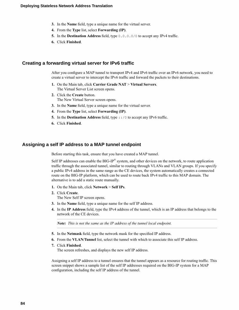
3. In the Name field, type a unique name for the virtual server.4. From the Type list, select Forwarding (IP).5. In the Destination Address field, type 0.0.0.0/0 to accept any IPv4 traffic.6. Click Finished.
Creating a forwarding virtual server for IPv6 traffic
After you configure a MAP tunnel to transport IPv4 and IPv6 traffic over an IPv6 network, you need tocreate a virtual server to intercept the IPv6 traffic and forward the packets to their destinations.
1. On the Main tab, click Carrier Grade NAT > Virtual Servers.The Virtual Server List screen opens.
2. Click the Create button.The New Virtual Server screen opens.
3. In the Name field, type a unique name for the virtual server.4. From the Type list, select Forwarding (IP).5. In the Destination Address field, type ::/0 to accept any IPv6 traffic.6. Click Finished.
Assigning a self IP address to a MAP tunnel endpoint
Before starting this task, ensure that you have created a MAP tunnel.
Self IP addresses can enable the BIG-IP® system, and other devices on the network, to route applicationtraffic through the associated tunnel, similar to routing through VLANs and VLAN groups. If you specifya public IPv4 address in the same range as the CE devices, the system automatically creates a connectedroute on the BIG-IP platform, which can be used to route back IPv4 traffic to this MAP domain. Thealternative is to add a static route manually.
1. On the Main tab, click Network > Self IPs.2. Click Create.
The New Self IP screen opens.3. In the Name field, type a unique name for the self IP address.4. In the IP Address field, type the IPv4 address of the tunnel, which is an IP address that belongs to the
network of the CE devices.
Note: This is not the same as the IP address of the tunnel local endpoint.
5. In the Netmask field, type the network mask for the specified IP address.6. From the VLAN/Tunnel list, select the tunnel with which to associate this self IP address.7. Click Finished.
The screen refreshes, and displays the new self IP address.
Assigning a self IP address to a tunnel ensures that the tunnel appears as a resource for routing traffic. Thisscreen snippet shows a sample list of the self IP addresses required on the BIG-IP system for a MAPconfiguration, including the self IP address of the tunnel.
84
Deploying Stateless Network Address Translation

Figure 16: Self IP addresses required for a MAP configuration
• The External self IP address is an IPv4 address on the side of the BIG-IP system that faces the Internet.• The Internal self IP address is an IPv6 address on the BIG-IP system, which is configured as a BR
device.• The Tunnel self IP address is the one you just created in this task.
Viewing MAP tunnel statistics
Using the tmsh command-line interface, you can view statistics to help you diagnose issues with MAPtunnels.
1. Access the tmsh command-line utility.2. Type this command at the prompt.
tmsh show net tunnels map profile
This example shows the statistics displayed for the MAP tunnel using the profile map-profile.
• Spoof Packets: The number of IPv4 packets that fail MAP self-consistency checks.• Misdirected Packets: The number of IPv4 packets sent to the wrong MAP domain or wrong protocol
number.• Address Sharing Ratio: The number of users sharing one IP address.• Ports per user: The number of ports each user behind the CE can use.
85
BIG-IP® CGNAT: Implementations


IPFIX Templates for CGNAT Events
Overview: IPFIX logging templates
The IP Flow Information Export (IPFIX) Protocol is a logging mechanism for IP events. This appendixdefines the IPFIX information elements (IEs) and templates used to log the F5 CGNAT events. An IE isthe smallest form of useful information in an IPFIX log message, such as an IP address or a timestamp forthe event. An IPFIX template is an ordered collection of specific IEs used to record one IP event, such asthe establishment of an inbound NAT64 session.
IPFIX information elements for CGNAT events
Information elements (IEs) are individual fields in an IPFIX template. An IPFIX template describes a singleCGNAT event. These tables list all the IEs used in F5 CGNAT events, and differentiate IEs defined byIANA from IEs defined by F5 products.
IANA-Defined IPFIX information elements
Information Elements
IANA maintains a list of standard IPFIX information elements (IEs), each with a unique element identifier,at http://www.iana.org/assignments/ipfix/ipfix.xml. The F5 CGNAT implementation uses a subset of theseIEs to publish CGNAT events. This subset is summarized in the table below. Please refer to the IANA sitefor the official description of each field.
Size (Bytes)IDInformation Element (IE)
412destinationIPv4Address
211destinationTransportPort
4235egressVRFID
4161flowDurationMilliseconds
8152flowStartMilliseconds
4234ingressVRFID
1230natEvent
1229natOriginatingAddressRealm
Variable284natPoolName
8323observationTimeMilliseconds
2362portRangeEnd
2361portRangeStart

Size (Bytes)IDInformation Element (IE)
2228postNAPTDestinationTransportPort
2227postNAPTSourceTransportPort
4226postNATDestinationIPv4Address
16282postNATDestinationIPv6Address
4225postNATSourceIPv4Address
14protocolIdentifier
48sourceIPv4Address
1627sourceIPv6Address
27sourceTransportPort
Note: IPFIX, unlike NetFlow v9, supports variable-length IEs, where the length is encoded within the fieldin the Data Record. NetFlow v9 collectors (and their variants) cannot correctly process variable-lengthIEs, so they are omitted from logs sent to those collector types.
IPFIX enterprise information elements
Description
IPFIX provides specifications for enterprises to define their own Information Elements. F5 currently doesnot use any non-standard IEs for CGNAT Events.
Individual IPFIX templates for each event
These tables specify the IPFIX templates used by F5 to publish CGNAT Events.
Each template contains a natEvent information element (IE). This element is currently defined by IANA tocontain values of 1 (Create Event), 2 (Delete Event) and 3 (Pool Exhausted). In the future, it is possible thatIANA will standardize additional values to distinguish between NAT44 and NAT64 events, and to allowfor additional types of NAT events. For example, thehttp://datatracker.ietf.org/doc/draft-ietf-behave-ipfix-nat-logging Internet Draft proposes additional valuesfor this IE for such events.
F5 uses the standard Create and Delete natEvent values in its IPFIX Data Records, rather than new(non-standard) specific values for NAT44 Create, NAT64 Create, and so on.
You can infer the semantics of each template (for example, whether or not the template applies to NAT44Create, NAT64 Create, or DS-Lite Create) from the template's contents rather than from distinct values inthe natEvent IE.
F5 CGNAT might generate different variants of NAT Session Create/Delete events, to cater to customerrequirements such as the need to publish destination address information, or to specifically omit suchinformation. Each variant has a distinct template.
The “Pool Exhausted” natEvent value is insufficiently descriptive to cover the possible NAT failure cases.Therefore, pending future updates to the natEvent Information Element, F5 uses some non-standard valuesto cover the following cases:
88
IPFIX Templates for CGNAT Events

• 10 – Translation Failure• 11 – Session Quota Exceeded• 12 – Port Quota Exceeded• 13 - Port Block Allocated• 14 - Port Block Released• 15 - Port Block Allocation (PBA) Client Block Limit Exceeded• 16 - PBA Port Quota Exceeded
The following tables enumerate and define the IPFIX templates, and include the possible natEvent valuesfor each template.
NAT44 session create – outbound variant
Description
This event is generated when a NAT44 client session is received from the subscriber side and the LSNprocess successfully translates the source address/port.
NotesSize(Bytes)
IDInformation Element (IE)
8323observationTimeMilliseconds
The "client" routing-domain ID.4234ingressVRFID
The "LSN" routing-domain ID.4235egressVRFID
48sourceIPv4Address
4225postNATSourceIPv4Address
14protocolIdentifier
27sourceTransportPort
2227postNAPTSourceTransportPort
0 (zero) if obscured.412destinationIPv4Address
0 (zero) if obscured.211destinationTransportPort
1 (private/internal realm, subscriberside).
1229natOriginatingAddressRealm
1 (for Create event).1230natEvent
NAT44 session delete – outbound variant
Description
This event is generated when a NAT44 client session is received from the subscriber side and the LSNprocess finishes the session.
89
BIG-IP® CGNAT: Implementations

By default, the BIG-IP® system does not record "delete session" events like this one. This default exists toimprove performance, but it prevents the system from ever sending IPFIX logs matching this template. Toenable "delete session" events and IPFIX logs matching this template, use the following tmsh command:
modify sys db log.lsn.session.end value enable
NotesSize(Bytes)
IDInformation Element (IE)
8323observationTimeMilliseconds
The "client" routing-domain ID.4234ingressVRFID
The "LSN" routing-domain ID.4235egressVRFID
48sourceIPv4Address
4225postNATSourceIPv4Address
14protocolIdentifier
27sourceTransportPort
2227postNAPTSourceTransportPort
0 (zero) if obscured.412destinationIPv4Address
0 (zero) if obscured.211destinationTransportPort
1 (private/internal realm, subscriberside).
1229natOriginatingAddressRealm
2 (for Delete event).1230natEvent
Start time, in ms since Epoch (1/1/1970).8152flowStartMilliseconds
Duration in ms.4161flowDurationMilliseconds
NAT44 session create – inbound variant
Description
This event is generated when an inbound NAT44 client session is received from the internet side and connectsto a client on the subscriber side.
NotesSize(Bytes)
IDInformation Element (IE)
8323observationTimeMilliseconds
The "LSN" routing-domain ID.4234ingressVRFID
The "client" routing-domain ID.4235egressVRFID
48sourceIPv4Address
14protocolIdentifier
27sourceTransportPort
412destinationIPv4Address
4226postNATDestinationIPv4Address
90
IPFIX Templates for CGNAT Events

NotesSize(Bytes)
IDInformation Element (IE)
211destinationTransportPort
2228postNAPTDestinationTransportPort
2 (public/external realm, Internet side).1229natOriginatingAddressRealm
1 (for Create event).1230natEvent
NAT44 session delete – inbound variant
Description
This event is generated when an inbound NAT44 client session is received from the internet side and connectsto a client on the subscriber side. This event is the deletion of the inbound connection.
By default, the BIG-IP® system does not record "delete session" events like this one. This default exists toimprove performance, but it prevents the system from ever sending IPFIX logs matching this template. Toenable "delete session" events and IPFIX logs matching this template, use the following tmsh command:
modify sys db log.lsn.session.end value enable
NotesSize(Bytes)
IDInformation Element (IE)
8323observationTimeMilliseconds
The "LSN" routing-domain ID.4234ingressVRFID
The "client" routing-domain ID.4235egressVRFID
48sourceIPv4Address
14protocolIdentifier
27sourceTransportPort
412destinationIPv4Address
4226postNATDestinationIPv4Address
211destinationTransportPort
2228postNAPTDestinationTransportPort
2 (public/external realm, Internet side).1229natOriginatingAddressRealm
2 (for Delete event).1230natEvent
Start time, in ms since Epoch (1/1/1970).8152flowStartMilliseconds
Duration in ms.4161flowDurationMilliseconds
91
BIG-IP® CGNAT: Implementations

NAT44 translation failed
Description
This event reports a NAT44 Translation Failure. The failure does not necessarily mean that all addressesor ports in the translation pool are already in use; the implementation may not be able to find a validtranslation within the allowed time constraints or number of lookup attempts, as may happen if the pool hasbecome highly fragmented.
NotesSize(Bytes)
IDInformation Element (IE)
8323observationTimeMilliseconds
The "client" routing-domain ID.4234ingressVRFID
48sourceIPv4Address
14protocolIdentifier
27sourceTransportPort
0 (zero) if obscured.412destinationIPv4Address
0 (zero) if obscured.211destinationTransportPort
10 for Transmission Failed.1230natEvent
This IE is omitted for NetFlow v9.Variable284natPoolName
NAT44 quota exceeded
Description
This event is generated when an administratively configured policy prevents a successful NAT44 translation.
NotesSize(Bytes)
IDInformation Element (IE)
8323observationTimeMilliseconds
The "client" routing-domain ID.4234ingressVRFID
48sourceIPv4Address
11 for Session Quota Exceeded, 12 forPort Quota Exceeded, 15 for PBA client
1230natEvent
block limit Exceeded, 16 for PBA PortQuota Exceeded.
This IE is omitted for NetFlow v9.Variable284natPoolName
92
IPFIX Templates for CGNAT Events
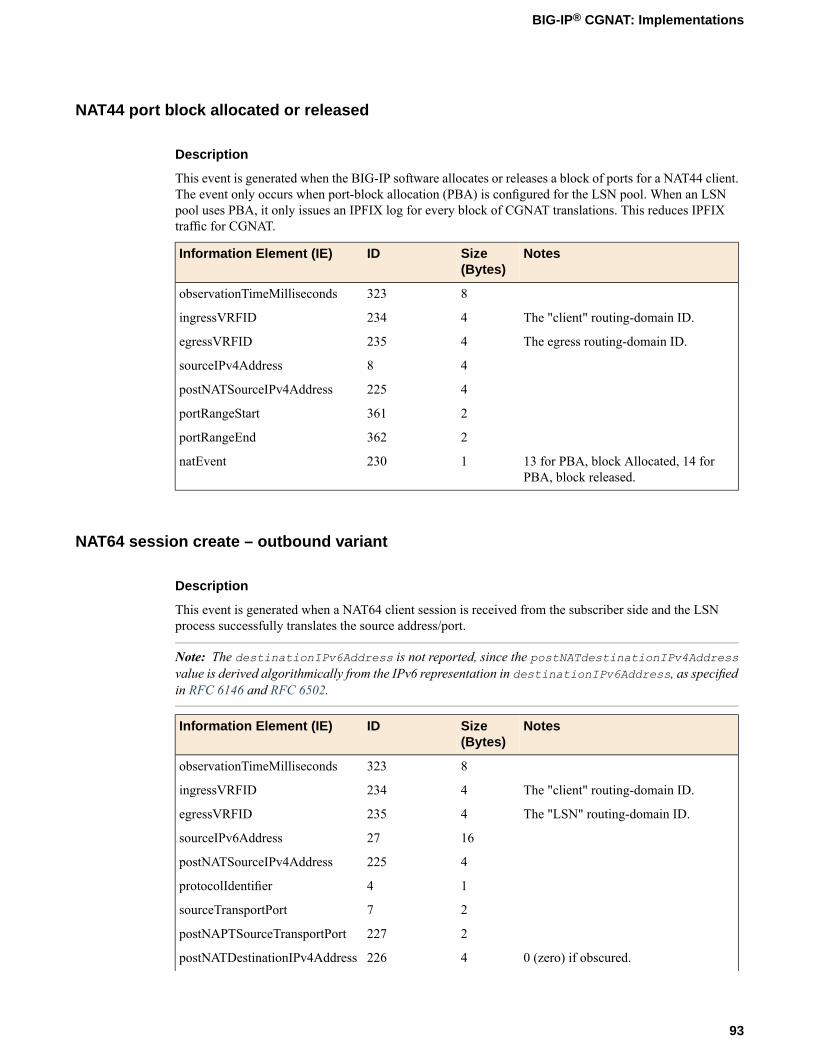
NAT44 port block allocated or released
Description
This event is generated when the BIG-IP software allocates or releases a block of ports for a NAT44 client.The event only occurs when port-block allocation (PBA) is configured for the LSN pool. When an LSNpool uses PBA, it only issues an IPFIX log for every block of CGNAT translations. This reduces IPFIXtraffic for CGNAT.
NotesSize(Bytes)
IDInformation Element (IE)
8323observationTimeMilliseconds
The "client" routing-domain ID.4234ingressVRFID
The egress routing-domain ID.4235egressVRFID
48sourceIPv4Address
4225postNATSourceIPv4Address
2361portRangeStart
2362portRangeEnd
13 for PBA, block Allocated, 14 forPBA, block released.
1230natEvent
NAT64 session create – outbound variant
Description
This event is generated when a NAT64 client session is received from the subscriber side and the LSNprocess successfully translates the source address/port.
Note: The destinationIPv6Address is not reported, since the postNATdestinationIPv4Addressvalue is derived algorithmically from the IPv6 representation in destinationIPv6Address, as specifiedin RFC 6146 and RFC 6502.
NotesSize(Bytes)
IDInformation Element (IE)
8323observationTimeMilliseconds
The "client" routing-domain ID.4234ingressVRFID
The "LSN" routing-domain ID.4235egressVRFID
1627sourceIPv6Address
4225postNATSourceIPv4Address
14protocolIdentifier
27sourceTransportPort
2227postNAPTSourceTransportPort
0 (zero) if obscured.4226postNATDestinationIPv4Address
93
BIG-IP® CGNAT: Implementations

NotesSize(Bytes)
IDInformation Element (IE)
0 (zero) if obscured.211destinationTransportPort
1 (private/internal realm, subscriberside).
1229natOriginatingAddressRealm
1 (for Create event).1230natEvent
NAT64 session delete – outbound variant
Description
This event is generated when a NAT64 client session is received from the subscriber side and the LSNprocess finishes the outbound session.
By default, the BIG-IP® system does not record "delete session" events like this one. This default exists toimprove performance, but it prevents the system from ever sending IPFIX logs matching this template. Toenable "delete session" events and IPFIX logs matching this template, use the following tmsh command:
modify sys db log.lsn.session.end value enable
NotesSize(Bytes)
IDInformation Element (IE)
8323observationTimeMilliseconds
The "client" routing-domain ID.4234ingressVRFID
The "LSN" routing-domain ID.4235egressVRFID
1627sourceIPv6Address
4225postNATSourceIPv4Address
14protocolIdentifier
27sourceTransportPort
2227postNAPTSourceTransportPort
0 (zero) if obscured.4226postNATDestinationIPv4Address
0 (zero) if obscured.211destinationTransportPort
1 (private/internal realm, subscriberside).
1229natOriginatingAddressRealm
2 (for Delete event).1230natEvent
Start time, in ms since Epoch (1/1/1970).8152flowStartMilliseconds
Duration in ms.4161flowDurationMilliseconds
94
IPFIX Templates for CGNAT Events

NAT64 session create – inbound variant
Description
This event is generated when a client session comes in from the internet side and successfully connects toa NAT64 client on the subscriber side.
Note: postNATSourceIPv6Address is not reported since this value can be derived algorithmically fromby appending the well-known NAT64 prefix 64:ff9b:: to sourceIPv4Address.
NotesSize(Bytes)
IDInformation Element (IE)
8323observationTimeMilliseconds
The "LSN" routing-domain ID.4234ingressVRFID
The "client" routing-domain ID.4235egressVRFID
48sourceIPv4Address
14protocolIdentifier
27sourceTransportPort
412destinationIPv4Address
16282postNATDestinationIPv6Address
211destinationTransportPort
2228postNAPTDestinationTransportPort
2 (public/external realm, Internet side).1229natOriginatingAddressRealm
1 (for Create event).1230natEvent
NAT64 session delete – inbound variant
Description
This event is generated when a client session comes in from the internet side and successfully connects toa NAT64 client on the subscriber side. This event is the deletion of the inbound connection.
Note: postNATSourceIPv6Address is not reported since this value can be derived algorithmically fromby appending the well-known NAT64 prefix 64:ff9b:: to sourceIPv4Address.
By default, the BIG-IP® system does not record "delete session" events like this one. This default exists toimprove performance, but it prevents the system from ever sending IPFIX logs matching this template. Toenable "delete session" events and IPFIX logs matching this template, use the following tmsh command:
modify sys db log.lsn.session.end value enable
NotesSize(Bytes)
IDInformation Element (IE)
8323observationTimeMilliseconds
95
BIG-IP® CGNAT: Implementations
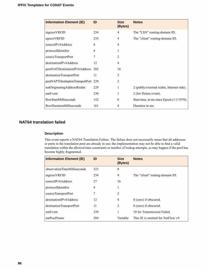
NotesSize(Bytes)
IDInformation Element (IE)
The "LSN" routing-domain ID.4234ingressVRFID
The "client" routing-domain ID.4235egressVRFID
48sourceIPv4Address
14protocolIdentifier
27sourceTransportPort
412destinationIPv4Address
16282postNATDestinationIPv6Address
211destinationTransportPort
2228postNAPTDestinationTransportPort
2 (public/external realm, Internet side).1229natOriginatingAddressRealm
2 (for Delete event).1230natEvent
Start time, in ms since Epoch (1/1/1970).8152flowStartMilliseconds
Duration in ms.4161flowDurationMilliseconds
NAT64 translation failed
Description
This event reports a NAT64 Translation Failure. The failure does not necessarily mean that all addressesor ports in the translation pool are already in use; the implementation may not be able to find a validtranslation within the allowed time constraints or number of lookup attempts, as may happen if the pool hasbecome highly fragmented.
NotesSize(Bytes)
IDInformation Element (IE)
8323observationTimeMilliseconds
The "client" routing-domain ID.4234ingressVRFID
1627sourceIPv6Address
14protocolIdentifier
27sourceTransportPort
0 (zero) if obscured.412destinationIPv4Address
0 (zero) if obscured.211destinationTransportPort
10 for Transmission Failed.1230natEvent
This IE is omitted for NetFlow v9.Variable284natPoolName
96
IPFIX Templates for CGNAT Events

NAT64 quota exceeded
Description
This event is generated when an administratively configured policy prevents a successful NAT64 translation.
NotesSize(Bytes)
IDInformation Element (IE)
8323observationTimeMilliseconds
The "client" routing-domain ID.4234ingressVRFID
1627sourceIPv6Address
11 for Session Quota Exceeded, 12 forPort Quota Exceeded, 15 for PBA client
1230natEvent
block limit Exceeded, 16 for PBA PortQuota Exceeded.
This IE is omitted for NetFlow v9.Variable284natPoolName
NAT64 port block allocated or released
Description
This event is generated when the BIG-IP software allocates or releases a block of ports for a NAT64 client.The event only occurs when port-block allocation (PBA) is configured for the LSN pool. When an LSNpool uses PBA, it only issues an IPFIX log for every block of CGNAT translations. This reduces IPFIXtraffic for CGNAT.
NotesSize(Bytes)
IDInformation Element (IE)
8323observationTimeMilliseconds
The "client" routing-domain ID.4234ingressVRFID
The egress routing-domain ID.4235egressVRFID
1627sourceIPv6Address
4225postNATSourceIPv4Address
2361portRangeStart
2362portRangeEnd
13 for PBA, block Allocated, 14 forPBA, block released.
1230natEvent
97
BIG-IP® CGNAT: Implementations
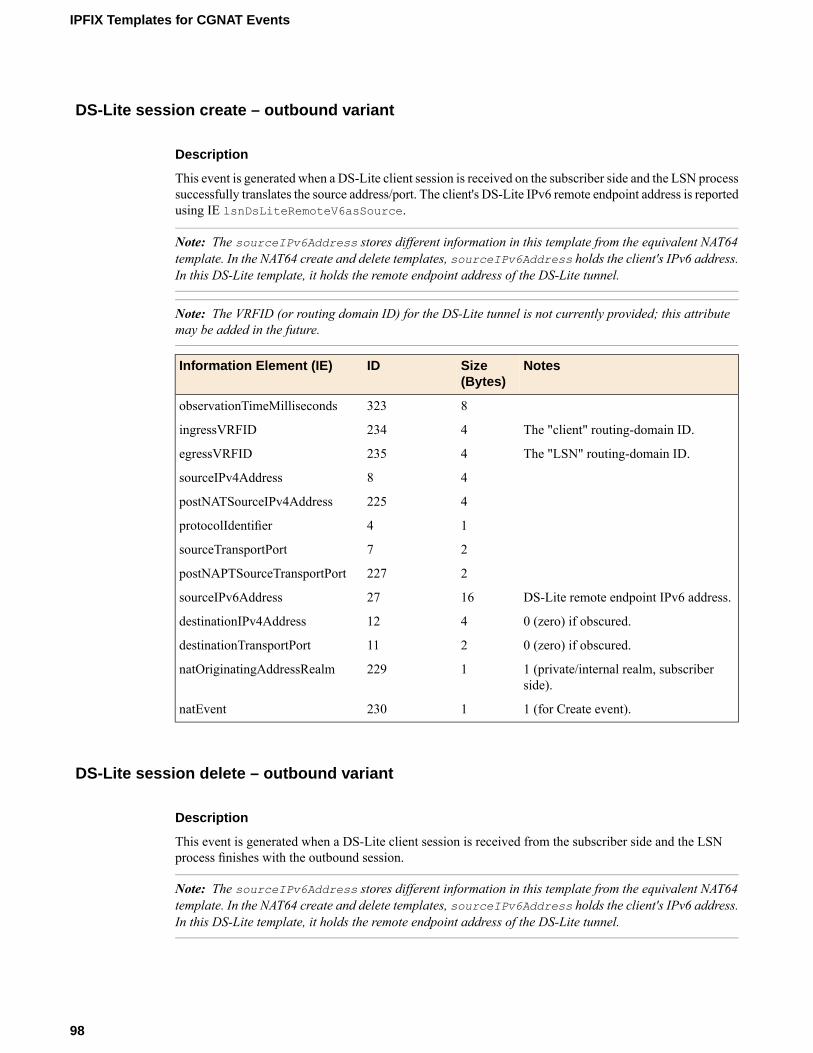
DS-Lite session create – outbound variant
Description
This event is generated when a DS-Lite client session is received on the subscriber side and the LSN processsuccessfully translates the source address/port. The client's DS-Lite IPv6 remote endpoint address is reportedusing IE lsnDsLiteRemoteV6asSource.
Note: The sourceIPv6Address stores different information in this template from the equivalent NAT64template. In the NAT64 create and delete templates, sourceIPv6Address holds the client's IPv6 address.In this DS-Lite template, it holds the remote endpoint address of the DS-Lite tunnel.
Note: The VRFID (or routing domain ID) for the DS-Lite tunnel is not currently provided; this attributemay be added in the future.
NotesSize(Bytes)
IDInformation Element (IE)
8323observationTimeMilliseconds
The "client" routing-domain ID.4234ingressVRFID
The "LSN" routing-domain ID.4235egressVRFID
48sourceIPv4Address
4225postNATSourceIPv4Address
14protocolIdentifier
27sourceTransportPort
2227postNAPTSourceTransportPort
DS-Lite remote endpoint IPv6 address.1627sourceIPv6Address
0 (zero) if obscured.412destinationIPv4Address
0 (zero) if obscured.211destinationTransportPort
1 (private/internal realm, subscriberside).
1229natOriginatingAddressRealm
1 (for Create event).1230natEvent
DS-Lite session delete – outbound variant
Description
This event is generated when a DS-Lite client session is received from the subscriber side and the LSNprocess finishes with the outbound session.
Note: The sourceIPv6Address stores different information in this template from the equivalent NAT64template. In the NAT64 create and delete templates, sourceIPv6Address holds the client's IPv6 address.In this DS-Lite template, it holds the remote endpoint address of the DS-Lite tunnel.
98
IPFIX Templates for CGNAT Events

Note: The VRFID (or routing domain ID) for the DS-Lite tunnel is not currently provided; this attributemay be added in the future.
By default, the BIG-IP® system does not record "delete session" events like this one. This default exists toimprove performance, but it prevents the system from ever sending IPFIX logs matching this template. Toenable "delete session" events and IPFIX logs matching this template, use the following tmsh command:
modify sys db log.lsn.session.end value enable
NotesSize(Bytes)
IDInformation Element (IE)
8323observationTimeMilliseconds
The "client" routing-domain ID.4234ingressVRFID
The "LSN" routing-domain ID.4235egressVRFID
48sourceIPv4Address
4225postNATSourceIPv4Address
14protocolIdentifier
27sourceTransportPort
2227postNAPTSourceTransportPort
DS-Lite remote endpoint IPv6 address.1627sourceIPv6Address
0 (zero) if obscured.412destinationIPv4Address
0 (zero) if obscured.211destinationTransportPort
1 (private/internal realm, subscriberside).
1229natOriginatingAddressRealm
2 (for Delete event).1230natEvent
Start time, in ms since Epoch (1/1/1970).8152flowStartMilliseconds
Duration in ms.4161flowDurationMilliseconds
DS-Lite session create – inbound variant
Description
This event is generated when an inbound client session comes in from the internet side and connects to aDS-Lite client on the subscriber side.
NotesSize(Bytes)
IDInformation Element (IE)
8323observationTimeMilliseconds
The "LSN" routing-domain ID.4234ingressVRFID
The "client" routing-domain ID.4235egressVRFID
48sourceIPv4Address
14protocolIdentifier
99
BIG-IP® CGNAT: Implementations

NotesSize(Bytes)
IDInformation Element (IE)
27sourceTransportPort
412destinationIPv4Address
DS-Lite remote endpoint IPv6 address.16282postNATDestinationIPv6Address
4226postNATDestinationIPv4Address
211destinationTransportPort
2228postNAPTDestinationTransportPort
2 (public/external realm, Internet side).1229natOriginatingAddressRealm
1 (for Create event).1230natEvent
DS-Lite session delete – inbound variant
Description
This event is generated when an inbound client session comes in from the internet side and connects to aDS-Lite client on the subscriber side. This event marks the end of the inbound connection, when theconnection is deleted.
By default, the BIG-IP® system does not record "delete session" events like this one. This default exists toimprove performance, but it prevents the system from ever sending IPFIX logs matching this template. Toenable "delete session" events and IPFIX logs matching this template, use the following tmsh command:
modify sys db log.lsn.session.end value enable
NotesSize(Bytes)
IDInformation Element (IE)
8323observationTimeMilliseconds
The "LSN" routing-domain ID.4234ingressVRFID
The "client" routing-domain ID.4235egressVRFID
48sourceIPv4Address
14protocolIdentifier
27sourceTransportPort
412destinationIPv4Address
16282postNATDestinationIPv6Address
4226postNATDestinationIPv4Address
211destinationTransportPort
2228postNAPTDestinationTransportPort
2 (public/external realm, Internet side).1229natOriginatingAddressRealm
2 (for Delete event).1230natEvent
Start time, in ms since Epoch (1/1/1970).8152flowStartMilliseconds
100
IPFIX Templates for CGNAT Events

NotesSize(Bytes)
IDInformation Element (IE)
Duration in ms.4161flowDurationMilliseconds
DS-Lite translation failed
Description
This event reports a DS-Lite Translation Failure. The failure does not necessarily mean that all addressesor ports in the translation pool are already in use; the implementation may not be able to find a validtranslation within the allowed time constraints or number of lookup attempts, as may happen if the pool hasbecome highly fragmented.
NotesSize(Bytes)
IDInformation Element (IE)
8323observationTimeMilliseconds
The "client" routing-domain ID.4234ingressVRFID
IPv4 address used by F5 CGNAT in theIPv4-mapped IPv6 format, for theDS-Lite tunnel terminated on the BIG-IP.
48sourceIPv4Address
14protocolIdentifier
27sourceTransportPort
IPv6 address for remote endpoint of theDS-Lite tunnel.
1627sourceIPv6Address
0 (zero) if obscured.412destinationIPv4Address
0 (zero) if obscured.211destinationTransportPort
10 for Transmission Failed.1230natEvent
This IE is omitted for NetFlow v9.Variable284natPoolName
DS-Lite quota exceeded
Description
This event is generated when an administratively configured policy prevents a successful NAT translationin a DS-Lite context.
NotesSize(Bytes)
IDInformation Element (IE)
8323observationTimeMilliseconds
The "client" routing-domain ID.4234ingressVRFID
48sourceIPv4Address
DS-Lite remote endpoint IPv6 address.1627sourceIPv6Address
11 for Session Quota Exceeded, 12 forPort Quota Exceeded, 15 for PBA client
1230natEvent
101
BIG-IP® CGNAT: Implementations
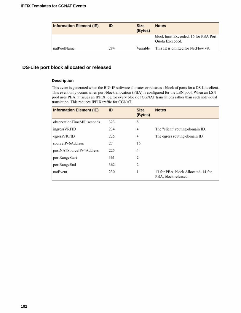
NotesSize(Bytes)
IDInformation Element (IE)
block limit Exceeded, 16 for PBA PortQuota Exceeded.
This IE is omitted for NetFlow v9.Variable284natPoolName
DS-Lite port block allocated or released
Description
This event is generated when the BIG-IP software allocates or releases a block of ports for a DS-Lite client.This event only occurs when port-block allocation (PBA) is configured for the LSN pool. When an LSNpool uses PBA, it issues an IPFIX log for every block of CGNAT translations rather than each individualtranslation. This reduces IPFIX traffic for CGNAT.
NotesSize(Bytes)
IDInformation Element (IE)
8323observationTimeMilliseconds
The "client" routing-domain ID.4234ingressVRFID
The egress routing-domain ID.4235egressVRFID
1627sourceIPv6Address
4225postNATSourceIPv4Address
2361portRangeStart
2362portRangeEnd
13 for PBA, block Allocated, 14 forPBA, block released.
1230natEvent
102
IPFIX Templates for CGNAT Events

Legal Notices and Acknowledgments
Legal NoticesAcknowledgments
Legal Notices
Publication Date
This document was published on February 14, 2018.
Publication Number
MAN-0428-03
Copyright
Copyright © 2014-2018, F5 Networks, Inc. All rights reserved.
F5 Networks, Inc. (F5) believes the information it furnishes to be accurate and reliable. However, F5 assumesno responsibility for the use of this information, nor any infringement of patents or other rights of thirdparties which may result from its use. No license is granted by implication or otherwise under any patent,copyright, or other intellectual property right of F5 except as specifically described by applicable userlicenses. F5 reserves the right to change specifications at any time without notice.
Trademarks
AAM, Access Policy Manager, Advanced Client Authentication, Advanced Firewall Manager, AdvancedRouting, AFM, Application Acceleration Manager, Application Security Manager, APM, ARX, AskF5,ASM, BIG-IP, BIG-IQ, Cloud Extender, CloudFucious, Cloud Manager, Clustered Multiprocessing, CMP,COHESION, Data Manager, DevCentral, DevCentral [DESIGN], DNS Express, DSC, DSI, Edge Client,Edge Gateway, Edge Portal, ELEVATE, EM, EnterpriseManager, ENGAGE, F5, F5 [DESIGN], F5 Certified[DESIGN], F5 Networks, F5 SalesXchange [DESIGN], F5 Synthesis, f5 Synthesis, F5 Synthesis [DESIGN],F5 TechXchange [DESIGN], Fast Application Proxy, Fast Cache, FirePass, Global Traffic Manager, GTM,GUARDIAN, iApps, IBR, iCall, Intelligent Browser Referencing, Intelligent Compression, IPv6 Gateway,iControl, iHealth, iQuery, iRules, iRules OnDemand, iSession, L7 Rate Shaping, LC, Link Controller,LineRate, LineRate Systems [DESIGN], Local Traffic Manager, LROS, LTM, Message Security Manager,MobileSafe, MSM, OneConnect, Packet Velocity, PEM, Policy Enforcement Manager, Protocol SecurityManager, PSM, Real Traffic Policy Builder, SalesXchange, ScaleN, SDAC (except in Japan), SDC, SignallingDelivery Controller, Solutions for an application world, Software Designed Applications Services, SSLAcceleration, StrongBox, SuperVIP, SYN Check, TCP Express, TDR, TechXchange, TMOS, TotALL,Traffic Management Operating System, Traffix (except Germany), Traffix [DESIGN] (except Germany),Transparent Data Reduction, UNITY, VAULT, vCMP, VE F5 [DESIGN], Versafe, Versafe [DESIGN],VIPRION, Virtual Clustered Multiprocessing, WebSafe, and ZoneRunner, are trademarks or service marksof F5 Networks, Inc., in the U.S. and other countries, and may not be used without F5's express writtenconsent.
All other product and company names herein may be trademarks of their respective owners.

Patents
This product may be protected by one or more patents indicated at:http://www.f5.com/about/guidelines-policies/patents
Export Regulation Notice
This product may include cryptographic software. Under the Export Administration Act, the United Statesgovernment may consider it a criminal offense to export this product from the United States.
RF Interference Warning
This is a Class A product. In a domestic environment this product may cause radio interference, in whichcase the user may be required to take adequate measures.
FCC Compliance
This equipment has been tested and found to comply with the limits for a Class A digital device pursuantto Part 15 of FCC rules. These limits are designed to provide reasonable protection against harmfulinterference when the equipment is operated in a commercial environment. This unit generates, uses, andcan radiate radio frequency energy and, if not installed and used in accordance with the instruction manual,may cause harmful interference to radio communications. Operation of this equipment in a residential areais likely to cause harmful interference, in which case the user, at his own expense, will be required to takewhatever measures may be required to correct the interference.
Anymodifications to this device, unless expressly approved by themanufacturer, can void the user's authorityto operate this equipment under part 15 of the FCC rules.
Canadian Regulatory Compliance
This Class A digital apparatus complies with Canadian ICES-003.
Standards Compliance
This product conforms to the IEC, European Union, ANSI/UL and Canadian CSA standards applicable toInformation Technology products at the time of manufacture.Legal Notices and Acknowledgments
Acknowledgments
This product includes software developed by Bill Paul.
This product includes software developed by Jonathan Stone.
This product includes software developed by Manuel Bouyer.
This product includes software developed by Paul Richards.
This product includes software developed by the NetBSD Foundation, Inc. and its contributors.
This product includes software developed by the Politecnico di Torino, and its contributors.
This product includes software developed by the Swedish Institute of Computer Science and its contributors.
This product includes software developed by the University of California, Berkeley and its contributors.
This product includes software developed by the Computer Systems Engineering Group at the LawrenceBerkeley Laboratory.
104
Legal Notices and Acknowledgments

This product includes software developed by Christopher G. Demetriou for the NetBSD Project.
This product includes software developed by Adam Glass.
This product includes software developed by Christian E. Hopps.
This product includes software developed by Dean Huxley.
This product includes software developed by John Kohl.
This product includes software developed by Paul Kranenburg.
This product includes software developed by Terrence R. Lambert.
This product includes software developed by Philip A. Nelson.
This product includes software developed by Herb Peyerl.
This product includes software developed by Jochen Pohl for the NetBSD Project.
This product includes software developed by Chris Provenzano.
This product includes software developed by Theo de Raadt.
This product includes software developed by David Muir Sharnoff.
This product includes software developed by SigmaSoft, Th. Lockert.
This product includes software developed for the NetBSD Project by Jason R. Thorpe.
This product includes software developed by Jason R. Thorpe for AndCommunications, http://www.and.com.
This product includes software developed for the NetBSD Project by Frank Van der Linden.
This product includes software developed for the NetBSD Project by John M. Vinopal.
This product includes software developed by Christos Zoulas.
This product includes software developed by the University of Vermont and State Agricultural College andGarrett A. Wollman.
This product includes software developed by Balazs Scheidler ([email protected]), which is protected underthe GNU Public License.
This product includes software developed by Niels Mueller ([email protected]), which is protected underthe GNU Public License.
In the following statement, "This software" refers to the Mitsumi CD-ROM driver: This software wasdeveloped by Holger Veit and Brian Moore for use with 386BSD and similar operating systems. "Similaroperating systems" includes mainly non-profit oriented systems for research and education, including butnot restricted to NetBSD, FreeBSD, Mach (by CMU).
This product includes software developed by the Apache Group for use in the Apache HTTP server project(http://www.apache.org/).
This product includes software licensed from Richard H. Porter under the GNU Library General PublicLicense (© 1998, Red Hat Software), www.gnu.org/copyleft/lgpl.html.
This product includes the standard version of Perl software licensed under the Perl Artistic License (© 1997,1998 TomChristiansen and Nathan Torkington). All rights reserved. Youmay find the most current standardversion of Perl at http://www.perl.com.
This product includes software developed by Jared Minch.
This product includes software developed by the OpenSSL Project for use in the OpenSSL Toolkit(http://www.openssl.org/).
This product includes cryptographic software written by Eric Young ([email protected]).
This product contains software based on oprofile, which is protected under the GNU Public License.
105
BIG-IP® CGNAT: Implementations
This product includes RRDtool software developed by Tobi Oetiker (http://www.rrdtool.com/index.html)and licensed under the GNU General Public License.
This product contains software licensed from Dr. Brian Gladman under the GNU General Public License(GPL).
This product includes software developed by the Apache Software Foundation (http://www.apache.org/).
This product includes Hypersonic SQL.
This product contains software developed by the Regents of the University of California, SunMicrosystems,Inc., Scriptics Corporation, and others.
This product includes software developed by the Internet Software Consortium.
This product includes software developed by Nominum, Inc. (http://www.nominum.com).
This product contains software developed by Broadcom Corporation, which is protected under the GNUPublic License.
This product contains software developed byMaxMind LLC, and is protected under the GNULesser GeneralPublic License, as published by the Free Software Foundation.
This product includes Intel QuickAssist kernel module, library, and headers software licensed under theGNU General Public License (GPL).
This product includes software licensed fromGerald Combs ([email protected]) under the GNUGeneralPublic License as published by the Free Software Foundation; either version 2 of the License, or any laterversion. Copyright ©1998 Gerald Combs.
This product includes software developed by Thomas Williams and Colin Kelley. Copyright ©1986 - 1993,1998, 2004, 2007
Permission to use, copy, and distribute this software and its documentation for any purpose with or withoutfee is hereby granted, provided that the above copyright notice appear in all copies and that both thatcopyright notice and this permission notice appear in supporting documentation. Permission to modify thesoftware is granted, but not the right to distribute the complete modified source code. Modifications are tobe distributed as patches to the released version. Permission to distribute binaries produced by compilingmodified sources is granted, provided you
1. distribute the corresponding source modifications from the released version in the form of a patch filealong with the binaries,
2. add special version identification to distinguish your version in addition to the base release versionnumber,
3. provide your name and address as the primary contact for the support of your modified version, and4. retain our contact information in regard to use of the base software.
Permission to distribute the released version of the source code alongwith corresponding sourcemodificationsin the form of a patch file is granted with same provisions 2 through 4 for binary distributions. This softwareis provided "as is" without express or implied warranty to the extent permitted by applicable law.
This product contains software developed by Google, Inc. Copyright ©2011 Google, Inc.
Permission is hereby granted, free of charge, to any person obtaining a copy of this software and associateddocumentation files (the "Software"), to deal in the Software without restriction, including without limitationthe rights to use, copy, modify, merge, publish, distribute, sublicense, and/or sell copies of the Software,and to permit persons to whom the Software is furnished to do so, subject to the following conditions:
The above copyright notice and this permission notice shall be included in all copies or substantial portionsof the Software.
THE SOFTWARE IS PROVIDED "AS IS", WITHOUT WARRANTY OF ANY KIND, EXPRESS ORIMPLIED, INCLUDING BUT NOT LIMITED TO THE WARRANTIES OF MERCHANTABILITY,FITNESS FOR A PARTICULAR PURPOSE ANDNONINFRINGEMENT. IN NO EVENT SHALL THE
106
Legal Notices and Acknowledgments

AUTHORS OR COPYRIGHT HOLDERS BE LIABLE FOR ANY CLAIM, DAMAGES OR OTHERLIABILITY, WHETHER IN ANACTIONOF CONTRACT, TORT OROTHERWISE, ARISING FROM,OUT OF OR IN CONNECTION WITH THE SOFTWARE OR THE USE OR OTHER DEALINGS INTHE SOFTWARE.
This product includes software developed by Jeremy Ashkenas and DocumentCloud, and distributed underthe MIT license. Copyright © 2010-2013 Jeremy Ashkenas, DocumentCloud.
This product includes gson software, distributed under the Apache License version 2.0. Copyright ©2008-2011 Google Inc.
This product includes ec2-tools software, copyright © 2008, Amazon Web Services, and licensed under theAmazon Software License. A copy of the License is located at http://aws.amazon.com/asl/ .
This product includes jxrlib software, copyright ©2009 Microsoft Corp. All rights reserved. Distributedunder the new BSD license.
This product includes node-uuid software, copyright © 2010-2012, Robert Kieffer, and distributed underthe MIT license.
This product includes opencsv software, which is distributed under the Apache 2.0 license.
This product includes owasp-jave-encoder software, copyright © 2014, Jeff Ichnowski, and distributedunder the New BSD license.Legal Notices and Acknowledgments
107
BIG-IP® CGNAT: Implementations


Index
6rdabout 77configuring 78creating tunnels for 78
6rd profilescreating 78
A
AFTR device, See DS-LiteALG, See ALG profile configuringALG profile
FTP 43RTSP 55SIP 48
ALG profiles8
and protocols supported 8configuring 10, 15, 19
application layer gateway, See ALG profile
B
B4 deviceand DS-Lite 21
border relay (BR)configuring for 6rd 78configuring for MAP 83
BR, See border relay (BR)
C
carrier-grade network address translation (CGNAT), SeeCGNATcarrier-grade network address translation (CGNAT) persistence,See CGNATCGN, See CGNATCGNAT
about 7about hairpinning 17, 22and deterministic NAT mapping 39–40and deterministic pools 36carrier-grade network address translation (CGNAT)persistence 8configuring iRule for 10, 15, 19, 46, 57creating NAT64 virtual server for LSN pool 14, 28creating tunnels 11creating virtual server for LSN pool 11, 18, 34, 37IPv4 prefixes 9IPv6 prefixes 9
CGNAT FTP to transfer filesoverview 43
CGNAT high-speed loggingoverview 65
CGNAT high-speed logging, overview 66CGNAT IPFIX logging
overview 71
CGNAT NAPT loggingoverview 25
CGNAT PBA loggingabout PBA translation mode 29overview 28
CGNAT PBA route domainsabout configuring 29
CGNAT pools, See LSN poolsCGNAT PPTP used for VPN tunnel
overview 59CGNAT RTSP to stream media
overview 54CGNAT SIP for multimedia sessions
overview 48CGNAT tunnels
creating 11collectors
for IPFIX 72
D
destinationsfor IPFIX logging 73for logging 68for logging locally 65for remote high-speed logging 68
deterministic address translation modeabout 35
deterministic assignment of translation addresses 7deterministic NAT
See also CGNATand mapping lookup, See DNAT utilitySee also CGNAT
DNAT, See deterministic address translation modednatutil
39commands 38
DNAT utility39–40
commands 38downloading 39overview 38
DS-Liteabout 21and AFTR devices 23creating AFTR endpoint 21–22creating tunnels for 22creating virtual server for 23IPFIX template
create inbound session 99create outbound session 98delete (finish) inbound session 100delete (finish) outbound session 98quota-exceeded event 101translation failure 101
verifying traffic 24
109
Index

F
file transfer protocol profile, See FTP profileforwarding virtual servers
83creating for IPv4 traffic 83creating for IPv6 traffic 84creating for tunnels 79
FTPand ALG profile 8
FTP ALG, See ALG profile FTPFTP ALG logging profile
creating 47FTP profile
creating 45FTP used to transfer files
overview 43
H
hairpinningand NAT64 exception 17, 22
high-speed loggingand CGNAT 65–66and LSN pools 66and server pools 67
I
IPFIXand server pools 72template
create inbound DS-Lite session 99create inbound NAT44 session 90create inbound NAT64 session 95create outbound DS-Lite session 98create outbound NAT44 session 89create outbound NAT64 session 93delete (finish) inbound DS-Lite session 100delete (finish) inbound NAT44 session 91delete (finish) inbound NAT64 session 95delete (finish) outbound DS-Lite session 98delete (finish) outbound NAT44 session 89delete (finish) outbound NAT64 session 94DS-Lite quota-exceeded event 101DS-Lite translation failure 101NAT44 PBA 93NAT44 quota-exceeded event 92NAT44 translation failure 92NAT64 PBA 97, 102NAT64 quota-exceeded event 97NAT64 translation failure 96
template overview 87IPFIX collectors
and destinations for log messages 73and publishers for log messages 73
IPFIX loggingand CGNAT, overview 71creating a destination 73
IP tunnelingand 6rd 77and DS-Lite 21
IP tunneling (continued)and MAP 80
IPv4and transition to IPv6 21, 77, 80
IPv4 over IPv6using MAP 80–81using MAP-T 81
IPv4 prefixes, See CGNATIPv6 over IPv4
using 6rd 77IPv6 prefixes, See CGNATiRules
and CGNAT 10, 15, 19, 46, 57
L
Large Scale NAT, See LSN poolslarge-scale network address translation (LSNAT), See CGNATlogging
and destinations 68, 73and formatted destinations 65and LSN pools 66and pools 67, 72and publishers 66, 69, 73and the local Syslog database 65
logging profileconfiguring FTP ALG profiles 47configuring LSN pools 70, 75configuring RTSP ALG profiles 58configuring SIP ALG profiles 54
log publisherconfiguring FTP ALG profiles 47configuring LSN pools 70, 75configuring RTSP ALG profiles 58configuring SIP ALG profiles 54
LSNIANA IPFIX IEs for 87–88
LSN logging profilecreating 69, 74
LSN poolconfiguring 70, 75
LSN poolscreating 9, 18, 45, 49, 56, 61creating a NAT64 14creating deterministic 36creating empty 52creating for PBA 33NAPT 26
M
MAP (Mapping of Address and Port)about 80–81configuring 82creating tunnels for 83viewing tunnel statistics for 85
MAP domaindefining 83
MAP profilescreating 83reporting 85
110
Index

MAP-Tabout 81
multimedia sessionsoverview using with SIP 48
N
NAPT 9, 18, 45, 49, 52, 56, 61napt log example 25NAPT logging
overview 25NAT44
about 17and network diagram 17IPFIX template
create inbound session 90create outbound session 89delete (finish) inbound session 91delete (finish) outbound session 89PBA 93quota-exceeded event 92translation failure 92
NAT64about 13and network diagram 13creating LSN pool 14example 13IPFIX template
create inbound session 95create outbound session 93delete (finish) inbound session 95delete (finish) outbound session 94PBA 97, 102quota-exceeded event 97translation failure 96
P
PBA logexamples 30
PBA loggingabout PBA translation mode 29overview 28
PBA modeabout configuring 29for address translation 29overview 28
PCP client address translationoverview 41
PCP profileadding to LSN pool 41creating 41
point-to-point tunneling protocol profile, See PPTP profilepools
creating LSN 66for high-speed logging 67for IPFIX 72
Port Block Allocation logging, See PBA loggingport block allocation of translation addresses 7PPTP
and ALG profile 8creating virtual server for LSN pool 63
PPTP profileabout 59creating 62defined 59log example 60
PPTP Profilelog example 30
PPTP used for VPN tunneloverview 59
private NAT, See CGNATprofiles
about PPTP 59configuring FTP ALG 47configuring RTSP ALG 58configuring SIP ALG 54creating for 6rd tunnel 78creating for MAP tunnel 83
publishersand logging 73for local Syslog logging 66
publishers, and logging 69
R
real time streaming protocol profile, See RTSP profileremote servers
and destinations for log messages 68and publishers for log messages 69for high-speed logging 67
routesand tunnels 80
RTSPand ALG profile 8
RTSP ALG logging profilecreating 58
RTSP profilecreating 56
RTSP used to stream mediaoverview 54
S
secure VPN tunneloverview creating with PPTP 59
self IP addressesand DS-Lite tunnels 23creating for IP tunnels 79creating for MAP tunnels 84
serversand destinations for log messages 68, 73and publishers for IPFIX logs 73and publishers for log messages 69for high-speed logging 67
session initiation protocol profile, See SIP profileSIP
and ALG profile 8SIP ALG, See ALG profile SIPSIP ALG logging profile
creating 53SIP profile
creating 50
111
Index

SIP used for multimedia sessionsoverview 48
static routeadding for GRE traffic 62
streaming mediaoverview using with RTSP 54
T
template, See IPFIXtransferring files
overview using with FTP 43tunnels
adding routes for 80and 6rd 77and DS-Lite 21and MAP 80and self IP addresses 23, 79, 84configuring for 6rd 78configuring for DS-Lite 22configuring for MAP 83creating 6rd profile for 78creating MAP profile for 83for CGNAT, See CGNAT tunnelsverifying DS-Lite traffic 24
V
v6rd, See 6rdv6rd profiles, See 6rd profilesvirtual server
creating for CGNAT 11, 14, 18, 28, 34, 37creating for PPTP 63creating for transferring files using an FTP profile. 46creating for transferring files using an RTSP profile. 57creating for transferring files using an SIP profile. 52creating for transferring files using a SIP profile. 51
virtual servers 83See also forwarding virtual serversSee also forwarding virtual servers
creating for DS-Lite 23See also forwarding virtual serversSee also forwarding virtual servers
VLANscreating for deterministic NAT 27, 33, 36creating for PBA NAT 27, 33, 36
VPN tunneloverview creating with PPTP 59
112
Index