big-ip tmos : concepts - support.f5.com · vlan assignment.....107 about viewing and modifying a...
TRANSCRIPT
BIG-IP® TMOS®: Concepts
Version 11.4

Table of Contents
Legal Notices.....................................................................................................9
Acknowledgments...........................................................................................11
Chapter 1: What Is the BIG-IP System?.................................................................................19
Chapter 2: General Configuration Properties.......................................................................21
TMOS general configuration properties...........................................................................22
About general device properties......................................................................................22
Updates to the IP geolocation database..........................................................................22
About network time protocol (NTP)..................................................................................23
About DNS configuration..................................................................................................23
About local-traffic properties............................................................................................23
Chapter 3: SSL Certificates for BIG-IP Devices....................................................................25
SSL Certificates for BIG-IP Devices.................................................................................26
Device certificates............................................................................................................26
Trusted device certificates................................................................................................27
Chapter 4: External File Management....................................................................................29
Introduction to external file management.........................................................................30
Data group files................................................................................................................30
About iFiles......................................................................................................................30
External monitor program files.........................................................................................30
SSL certificate files..........................................................................................................31
Chapter 5: Platform Properties...............................................................................................33
Introduction to platform properties...................................................................................34
General properties...........................................................................................................34
Redundant device properties...........................................................................................35
User administration properties.........................................................................................35
Administrative account passwords...................................................................................35
SSH access configuration................................................................................................35
Chapter 6: Archives.................................................................................................................37
About archives.................................................................................................................38
About saving archives......................................................................................................38
About archive restoration.................................................................................................39
3
Table of Contents

Chapter 7: Services.................................................................................................................41
Managing BIG-IP System Services..................................................................................42
Chapter 8: Working with Partitions........................................................................................43
About administrative partitions.........................................................................................44
About partition Common..................................................................................................44
About the current partition................................................................................................45
Object referencing between partitions..............................................................................45
Relationship of partitions to user accounts......................................................................46
Chapter 9: Working with Folders............................................................................................49
About folders on the BIG-IP system.................................................................................50
Relationship of folders to partitions..................................................................................50
Folder and object naming.................................................................................................50
Object referencing between folders..................................................................................50
Chapter 10: Users....................................................................................................................51
Introduction to user account management.......................................................................52
User account types..........................................................................................................52
Administrative partitions...................................................................................................53
What are user roles?........................................................................................................54
User roles on the BIG-IP system...........................................................................54
Default user roles.............................................................................................................56
Effect of user roles on objects within partitions................................................................57
Local user account management.....................................................................................57
Admin account configuration............................................................................................57
About secure password policy configuration....................................................................58
Configuration settings for a secure password policy.............................................58
User authentication lockout..............................................................................................60
Local user account creation.............................................................................................60
Properties of a local BIG-IP system user account.................................................60
Local user account view...................................................................................................61
Local user account modification.......................................................................................62
Delete local user accounts...............................................................................................62
Remote user account management.................................................................................63
Remote user-account server specification.......................................................................63
Authorization for remote accounts...................................................................................64
Default remote-user authorization....................................................................................64
Authorization for an individual user account....................................................................65
Authorization for groups of user accounts........................................................................66
Values for the remote role variable........................................................................66
Partition access................................................................................................................66
4
Table of Contents
About viewing remote user accounts...............................................................................67
About auditing user access to the system........................................................................67
Chapter 11: Logging................................................................................................................69
BIG-IP system logging overview......................................................................................70
Types of log messages.....................................................................................................70
Existing Syslog configurations.........................................................................................70
Remote storage of log messages....................................................................................70
Local storage of log messages........................................................................................71
Log level settings for BIG-IP system events.....................................................................72
About local Syslog logging...............................................................................................72
Logging system events....................................................................................................73
Logging BIG-IP system configuration changes (audit logging)........................................73
Code expansion in Syslog log messages........................................................................73
About enabling and disabling auditing logging.................................................................74
About remote logging using Syslog-ng............................................................................74
Chapter 12: Interface Concepts..............................................................................................75
Introduction to BIG-IP system interfaces..........................................................................76
About link layer discovery protocol...................................................................................76
Interface properties..........................................................................................................77
Interface naming conventions................................................................................77
Viewing interface information and media properties.............................................78
Interface state........................................................................................................78
Fixed Requested Media........................................................................................78
About flow control..................................................................................................78
About the LLDP property.......................................................................................79
LLDP Attributes.....................................................................................................79
About interface mirroring..................................................................................................79
Neighbor settings.............................................................................................................79
Related configuration tasks..............................................................................................80
Chapter 13: Self IP Addresses................................................................................................81
Introduction to self IP addresses......................................................................................82
Types of self IP addresses...............................................................................................82
Self IP addresses and MAC addresses...........................................................................82
Self IP addresses for SNATs............................................................................................83
Self IP address properties................................................................................................83
Chapter 14: Packet Filters.......................................................................................................85
Introduction to packet filtering..........................................................................................86
Global settings.................................................................................................................86
Global properties..............................................................................................................86
5
Table of Contents
Global exemptions............................................................................................................87
Protocols...............................................................................................................87
MAC addresses.....................................................................................................88
IP addresses.........................................................................................................88
VLANs...................................................................................................................88
Order of packet filter rules................................................................................................89
About the action setting in packet filter rules....................................................................89
Rate class assignment.....................................................................................................90
One or more VLANs.........................................................................................................90
Logging............................................................................................................................90
About filter expression creation........................................................................................90
Chapter 15: Rate Shaping.......................................................................................................91
Introduction to rate shaping..............................................................................................92
About rate classes............................................................................................................92
Rate class name..............................................................................................................93
Base rate..........................................................................................................................93
Ceiling rate.......................................................................................................................93
Burst size.........................................................................................................................93
Depleting the burst reservoir............................................................................................94
Replenishing a burst reservoir.........................................................................................94
About specifying a non-zero burst size ...........................................................................94
About the direction setting...............................................................................................95
About the parent class.....................................................................................................96
About shaping policy........................................................................................................96
About queue method........................................................................................................96
About drop policy.............................................................................................................97
Chapter 16: Spanning Tree Protocol......................................................................................99
Introduction to spanning tree protocols..........................................................................100
About STP protocol........................................................................................................100
About the RSTP protocol...............................................................................................100
About the MSTP protocol...............................................................................................101
About spanning tree with legacy bridges.......................................................................101
Configuration overview...................................................................................................102
Spanning tree mode.......................................................................................................102
Global timers..................................................................................................................103
About the hello time option..................................................................................103
About the maximum age option...........................................................................103
About the forward delay option............................................................................103
About the transmit hold count option..............................................................................104
MSTP-specific global properties....................................................................................104
Management of spanning tree instances.......................................................................104
Spanning tree instances list................................................................................105
6
Table of Contents
About spanning tree instance (MSTP-only) creation...........................................105
About instance ID assignment.............................................................................106
Bridge priority......................................................................................................106
VLAN assignment................................................................................................107
About viewing and modifying a spanning tree instance......................................107
About deleting a spanning tree instance or its members (MSTP-only)...............107
Interfaces for spanning tree............................................................................................107
Enabling and disabling spanning tree.................................................................108
STP link type.......................................................................................................108
STP edge port.....................................................................................................108
About spanning tree protocol reset.....................................................................109
About managing interfaces for a specific instance..............................................109
About viewing a list of interface IDs for an instance............................................109
About port roles...................................................................................................109
Port states...........................................................................................................110
Settings to configure for an interface for a specific instance...............................110
Chapter 17: Trunks................................................................................................................113
Introduction to trunks.....................................................................................................114
How do trunks work?.....................................................................................................114
Overview of LACP..........................................................................................................115
Trunk name....................................................................................................................115
Interfaces for a trunk......................................................................................................115
About enabling LACP.....................................................................................................116
LACP mode....................................................................................................................116
LACP timeout.................................................................................................................116
Link selection policy.......................................................................................................117
Automatic link selection..................................................................................................117
Maximum bandwidth link selection.................................................................................118
Frame distribution hash..................................................................................................118
Chapter 18: VLANs and VLAN Groups................................................................................119
Introduction to virtual LANs............................................................................................120
VLANs on a BIG-IP system............................................................................................120
Default VLAN configuration.................................................................................120
VLAN name.........................................................................................................121
VLAN tags...........................................................................................................121
Interface assignments.........................................................................................122
Port-based access to VLANs..............................................................................122
Tag-based access to VLANs...............................................................................122
Source checking..................................................................................................123
Maximum transmission units...............................................................................124
VLAN-based fail-safe...........................................................................................124
Auto last hop.......................................................................................................124
7
Table of Contents

About the CMP hash setting................................................................................124
Maintaining the L2 forwarding table.....................................................................124
About sFlow polling intervals and sampling rates...............................................125
About VLAN groups.......................................................................................................125
About VLAN group names...................................................................................126
VLAN group ID....................................................................................................126
About transparency mode...................................................................................126
About traffic bridging...........................................................................................126
About traffic bridging with standby units..............................................................126
About host exclusion from proxy ARP forwarding...............................................127
VLAN association with a self IP address........................................................................127
VLAN assignment to route domains...............................................................................127
Overview: Bridging VLAN and VXLAN networks...........................................................128
About Virtual eXtended LAN (VXLAN)................................................................129
Chapter 19: Failsafe...............................................................................................................131
About system fail-safe....................................................................................................132
About VLAN fail-safe......................................................................................................132
About gateway fail-safe..................................................................................................132
8
Table of Contents
Legal Notices
Publication Date
This document was published on May 15, 2013.
Publication Number
MAN-0378-04
Copyright
Copyright © 2012-2014, F5 Networks, Inc. All rights reserved.
F5 Networks, Inc. (F5) believes the information it furnishes to be accurate and reliable. However, F5 assumesno responsibility for the use of this information, nor any infringement of patents or other rights of thirdparties which may result from its use. No license is granted by implication or otherwise under any patent,copyright, or other intellectual property right of F5 except as specifically described by applicable userlicenses. F5 reserves the right to change specifications at any time without notice.
Trademarks
AAM, Access Policy Manager, Advanced Client Authentication, Advanced Firewall Manager, AdvancedRouting, AFM, Alive With F5, APM, Application Acceleration Manager, Application Security Manager,ARX, AskF5, ASM, BIG-IP, BIG-IQ, Cloud Extender, CloudFucious, Cloud Manager, ClusteredMultiprocessing, CMP, COHESION, Data Manager, DevCentral, DevCentral [DESIGN], DNS Express,DSC, DSI, Edge Client, Edge Gateway, Edge Portal, ELEVATE, EM, Enterprise Manager, ENGAGE, F5,F5 [DESIGN], F5 Certified [DESIGN], F5 Networks, Fast Application Proxy, Fast Cache, FirePass, GlobalTrafficManager, GTM,GUARDIAN, iApps, IBR, Intelligent Browser Referencing, Intelligent Compression,IPv6 Gateway, iControl, iHealth, iQuery, iRules, iRules OnDemand, iSession, L7 Rate Shaping, LC, LinkController, Local TrafficManager, LTM, LineRate, LineRate Systems [DESIGN], LROS,Message SecurityManager, MSM, OneConnect, Packet Velocity, PEM, Policy Enforcement Manager, Protocol SecurityManager, PSM, Real Traffic Policy Builder, ScaleN, Signalling Delivery Controller, SDC, SSLAcceleration,StrongBox, SuperVIP, SYN Check, TCP Express, TDR, TMOS, Traffic Management Operating System,Traffix Systems, Traffix Systems (DESIGN), Transparent Data Reduction, UNITY, VAULT, VIPRION,vCMP, VE F5 [DESIGN], Virtual Clustered Multiprocessing, WA, WAN Optimization Manager,WebAccelerator, WOM, and ZoneRunner, are trademarks or service marks of F5 Networks, Inc., in theU.S. and other countries, and may not be used without F5's express written consent.
All other product and company names herein may be trademarks of their respective owners.
Patents
This product may be protected by one or more patents indicated at:http://www.f5.com/about/guidelines-policies/patents
Export Regulation Notice
This product may include cryptographic software. Under the Export Administration Act, the United Statesgovernment may consider it a criminal offense to export this product from the United States.
RF Interference Warning
This is a Class A product. In a domestic environment this product may cause radio interference, in whichcase the user may be required to take adequate measures.

FCC Compliance
This equipment has been tested and found to comply with the limits for a Class A digital device pursuantto Part 15 of FCC rules. These limits are designed to provide reasonable protection against harmfulinterference when the equipment is operated in a commercial environment. This unit generates, uses, andcan radiate radio frequency energy and, if not installed and used in accordance with the instruction manual,may cause harmful interference to radio communications. Operation of this equipment in a residential areais likely to cause harmful interference, in which case the user, at his own expense, will be required to takewhatever measures may be required to correct the interference.
Anymodifications to this device, unless expressly approved by themanufacturer, can void the user's authorityto operate this equipment under part 15 of the FCC rules.
Canadian Regulatory Compliance
This Class A digital apparatus complies with Canadian ICES-003.
Standards Compliance
This product conforms to the IEC, European Union, ANSI/UL and Canadian CSA standards applicable toInformation Technology products at the time of manufacture.
10
Legal Notices

Acknowledgments
This product includes software developed by Bill Paul.
This product includes software developed by Jonathan Stone.
This product includes software developed by Manuel Bouyer.
This product includes software developed by Paul Richards.
This product includes software developed by the NetBSD Foundation, Inc. and its contributors.
This product includes software developed by the Politecnico di Torino, and its contributors.
This product includes software developed by the Swedish Institute of Computer Science and its contributors.
This product includes software developed by the University of California, Berkeley and its contributors.
This product includes software developed by the Computer Systems Engineering Group at the LawrenceBerkeley Laboratory.
This product includes software developed by Christopher G. Demetriou for the NetBSD Project.
This product includes software developed by Adam Glass.
This product includes software developed by Christian E. Hopps.
This product includes software developed by Dean Huxley.
This product includes software developed by John Kohl.
This product includes software developed by Paul Kranenburg.
This product includes software developed by Terrence R. Lambert.
This product includes software developed by Philip A. Nelson.
This product includes software developed by Herb Peyerl.
This product includes software developed by Jochen Pohl for the NetBSD Project.
This product includes software developed by Chris Provenzano.
This product includes software developed by Theo de Raadt.
This product includes software developed by David Muir Sharnoff.
This product includes software developed by SigmaSoft, Th. Lockert.
This product includes software developed for the NetBSD Project by Jason R. Thorpe.
This product includes software developed by Jason R. Thorpe for AndCommunications, http://www.and.com.
This product includes software developed for the NetBSD Project by Frank Van der Linden.
This product includes software developed for the NetBSD Project by John M. Vinopal.
This product includes software developed by Christos Zoulas.
This product includes software developed by the University of Vermont and State Agricultural College andGarrett A. Wollman.
This product includes software developed by Balazs Scheidler ([email protected]), which is protected underthe GNU Public License.
This product includes software developed by Niels Mueller ([email protected]), which is protected underthe GNU Public License.

In the following statement, This software refers to theMitsumi CD-ROMdriver: This software was developedby Holger Veit and Brian Moore for use with 386BSD and similar operating systems. Similar operatingsystems includes mainly non-profit oriented systems for research and education, including but not restrictedto NetBSD, FreeBSD, Mach (by CMU).
This product includes software developed by the Apache Group for use in the Apache HTTP server project(http://www.apache.org/).
This product includes software licensed from Richard H. Porter under the GNU Library General PublicLicense (© 1998, Red Hat Software), www.gnu.org/copyleft/lgpl.html.
This product includes the standard version of Perl software licensed under the Perl Artistic License (© 1997,1998 TomChristiansen and Nathan Torkington). All rights reserved. Youmay find the most current standardversion of Perl at http://www.perl.com.
This product includes software developed by Jared Minch.
This product includes software developed by the OpenSSL Project for use in the OpenSSL Toolkit(http://www.openssl.org/).
This product includes cryptographic software written by Eric Young ([email protected]).
This product contains software based on oprofile, which is protected under the GNU Public License.
This product includes software with glib library utility functions, which is protected under the GNU PublicLicense.
This product includes software with grub2 bootloader functions, which is protected under the GNU PublicLicense.
This product includes software with the Intel Gigabit Linux driver, which is protected under the GNU PublicLicense. Copyright ©1999 - 2012 Intel Corporation.
This product includes software with the Intel 10 Gigabit PCI Express Linux driver, which is protected underthe GNU Public License. Copyright ©1999 - 2012 Intel Corporation.
This product includes RRDtool software developed by Tobi Oetiker (http://www.rrdtool.com/index.html)and licensed under the GNU General Public License.
This product contains software licensed from Dr. Brian Gladman under the GNU General Public License(GPL).
This product includes software developed by the Apache Software Foundation (http://www.apache.org/).
This product includes Hypersonic SQL.
This product contains software developed by the Regents of the University of California, SunMicrosystems,Inc., Scriptics Corporation, and others.
This product includes software developed by the Internet Software Consortium.
This product includes software developed by Nominum, Inc. (http://www.nominum.com).
This product contains software developed by Broadcom Corporation, which is protected under the GNUPublic License.
This product contains software developed byMaxMind LLC, and is protected under the GNULesser GeneralPublic License, as published by the Free Software Foundation.
This product includes software developed by Andrew Tridgell, which is protected under the GNU PublicLicense, copyright ©1992-2000.
This product includes software developed by Jeremy Allison, which is protected under the GNU PublicLicense, copyright ©1998.
This product includes software developed by Guenther Deschner, which is protected under the GNU PublicLicense, copyright ©2008.
12
Acknowledgments
This product includes software developed by www.samba.org, which is protected under the GNU PublicLicense, copyright ©2007.
This product includes software from Allan Jardine, distributed under the MIT License.
This product includes software from Trent Richardson, distributed under the MIT License.
This product includes vmbus drivers distributed by Microsoft Corporation.
This product includes software from Cavium.
This product includes software from Webroot, Inc.
This product includes software from Maxmind, Inc.
This product includes software from OpenVision Technologies, Inc. Copyright ©1993-1996, OpenVisionTechnologies, Inc. All Rights Reserved.
This product includes software developed by Matt Johnson, distributed under the MIT License. Copyright©2012.
Permission is hereby granted, free of charge, to any person obtaining a copy of this software and associateddocumentation files (the "Software"), to deal in the Software without restriction, including without limitationthe rights to use, copy, modify, merge, publish, distribute, sublicense, and/or sell copies of the Software,and to permit persons to whom the Software is furnished to do so, subject to the following conditions:
The above copyright notice and this permission notice shall be included in all copies or substantial portionsof the Software.
THE SOFTWARE IS PROVIDED "AS IS", WITHOUT WARRANTY OF ANY KIND, EXPRESS ORIMPLIED, INCLUDING BUT NOT LIMITED TO THE WARRANTIES OF MERCHANTABILITY,FITNESS FOR A PARTICULAR PURPOSE ANDNONINFRINGEMENT. IN NO EVENT SHALL THEAUTHORS OR COPYRIGHT HOLDERS BE LIABLE FOR ANY CLAIM, DAMAGES OR OTHERLIABILITY, WHETHER IN ANACTIONOF CONTRACT, TORT OROTHERWISE, ARISING FROM,OUT OF OR IN CONNECTION WITH THE SOFTWARE OR THE USE OR OTHER DEALINGS INTHE SOFTWARE.
This product includes software from NLnetLabs. Copyright ©2005, 2006. All Rights Reserved.
Redistribution and use in source and binary forms, with or without modification, are permitted providedthat the following conditions are met:
• Redistributions of source code must retain the above copyright notice, this list of conditions and thefollowing disclaimer.
• Redistributions in binary form must reproduce the above copyright notice, this list of conditions and thefollowing disclaimer in the documentation and/or other materials provided with the distribution.
• Neither the name of NLnetLabs nor the names of its contributors may be used to endorse or promoteproducts derived from this software without specific prior written permission.
THIS SOFTWARE IS PROVIDED BY THE COPYRIGHT HOLDERS AND CONTRIBUTORS "AS IS"AND ANY EXPRESS OR IMPLIED WARRANTIES, INCLUDING, BUT NOT LIMITED TO, THEIMPLIEDWARRANTIES OFMERCHANTABILITYAND FITNESS FORA PARTICULAR PURPOSEARE DISCLAIMED. IN NO EVENT SHALL THE COPYRIGHT OWNER OR CONTRIBUTORS BELIABLE FOR ANY DIRECT, INDIRECT, INCIDENTAL, SPECIAL, EXEMPLARY, ORCONSEQUENTIAL DAMAGES (INCLUDING, BUT NOT LIMITED TO, PROCUREMENT OFSUBSTITUTE GOODS OR SERVICES; LOSS OF USE, DATA, OR PROFITS; OR BUSINESSINTERRUPTION) HOWEVER CAUSED AND ON ANY THEORY OF LIABILITY, WHETHER INCONTRACT, STRICTLIABILITY,ORTORT (INCLUDINGNEGLIGENCEOROTHERWISE)ARISINGIN ANYWAY OUT OF THE USE OF THIS SOFTWARE, EVEN IF ADVISED OF THE POSSIBILITYOF SUCH DAMAGE.
This product includes GRand Unified Bootloader (GRUB) software developed under the GNU PublicLicense, copyright ©2007.
13
BIG-IP® TMOS®: Concepts
This product includes Intel QuickAssist kernel module, library, and headers software licensed under theGNU General Public License (GPL).
This product includes gd-libgd library software developed by the following in accordance with the followingcopyrights:
• Portions copyright©1994, 1995, 1996, 1997, 1998, 2000, 2001, 2002 by Cold Spring Harbor Laboratory.Funded under Grant P41-RR02188 by the National Institutes of Health.
• Portions copyright ©1996, 1997, 1998, 1999, 2000, 2001, 2002 by Boutell.Com, Inc.• Portions relating to GD2 format copyright ©1999, 2000, 2001, 2002 Philip Warner.• Portions relating to PNG copyright ©1999, 2000, 2001, 2002 Greg Roelofs.• Portions relating to gdttf.c copyright ©1999, 2000, 2001, 2002 John Ellson ([email protected]).• Portions relating to gdft.c copyright ©2001, 2002 John Ellson ([email protected]).• Portions copyright ©2000, 2001, 2002, 2003, 2004, 2005, 2006, 2007 2008 Pierre-Alain Joye
([email protected]).• Portions relating to JPEG and to color quantization copyright ©2000, 2001, 2002, Doug Becker and
copyright ©1994, 1995, 1996, 1997, 1998, 1999, 2000, 2001, 2002, Thomas G. Lane. This software isbased in part on the work of the Independent JPEG Group.
• Portions relating to WBMP copyright 2000, 2001, 2002 Maurice Szmurlo and Johan Van den Brande.Permission has been granted to copy, distribute and modify gd in any context without fee, including acommercial application, provided that this notice is present in user-accessible supporting documentation.
This product includes software developed by Oracle America, Inc. Copyright ©2012.
1. Java Technology Restrictions. Licensee shall not create, modify, change the behavior of, or authorizelicensees of licensee to create, modify, or change the behavior of, classes, interfaces, or subpackagesthat are in any way identified as "java", "javax”, "sun" or similar convention as specified by Oracle inany naming convention designation. In the event that Licensee creates an additional API(s) which: (a)extends the functionality of a Java Environment; and (b) is exposed to third party software developersfor the purpose of developing additional software which invokes such additional API, Licensee mustpromptly publish broadly an accurate specification for such API for free use by all developer.
2. Trademarks and Logos. This License does not authorize an end user licensee to use any Oracle America,Inc. name, trademark, service mark, logo or icon. The end user licensee acknowledges that Oracle ownsthe Java trademark and all Java-related trademarks, logos and icon including the Coffee Cup and Duke("Java Marks") and agrees to: (a) comply with the Java Trademark Guidelines athttp://www.oraclc.com/html/3party.html; (b) not do anything harmful to or inconsistent with Oracle'srights in the Java Marks; and (c) assist Oracle in protecting those rights, including assigning to Oracleany rights acquired by Licensee in any Java Mark.
3. Source Code. Software may contain source code that, unless expressly licensed for other purposes, isprovided solely for reference purposes pursuant to the terms of your license. Source code may not beredistributed unless expressly provided for in the terms of your license.
4. Third Party Code. Additional copyright notices and license terms applicable to portion of the Softwareare set forth in the THIRDPARTYLICENSEREADME.txt file.
5. Commercial Features. Use of the Commercial Features for any commercial or production purposerequires a separate license from Oracle. "Commercial Features" means those features identified in TableI-I (Commercial Features In Java SE Product Editions) of tile Software documentation accessible athttp://www.oracle.com/technetwork/java/javase/documentation/index.html.
This product includes utilities developed by Linus Torvalds for inspecting devices connected to a USB bus.
This product includes perl-PHP-Serialization software, developed by Jesse Brown, copyright ©2003, anddistributed under the Perl Development Artistic License (http://dev.perl.org/licenses/artistic.html).
This product includes software licensed fromGerald Combs ([email protected]) under the GNUGeneralPublic License as published by the Free Software Foundation; either version 2 of the License, or any laterversion. Copyright ©1998 Gerald Combs.
14
Acknowledgments
This product includes software licensed from Rémi Denis-Courmont under the GNULibrary General PublicLicense. Copyright ©2006 - 2011.
This product includes software developed by jQuery Foundation and other contributors, distributed underthe MIT License. Copyright ©2012 jQuery Foundation and other contributors (http://jquery.com/).
Permission is hereby granted, free of charge, to any person obtaining a copy of this software and associateddocumentation files (the "Software"), to deal in the Software without restriction, including without limitationthe rights to use, copy, modify, merge, publish, distribute, sublicense, and/or sell copies of the Software,and to permit persons to whom the Software is furnished to do so, subject to the following conditions:
The above copyright notice and this permission notice shall be included in all copies or substantial portionsof the Software.
THE SOFTWARE IS PROVIDED "AS IS", WITHOUT WARRANTY OF ANY KIND, EXPRESS ORIMPLIED, INCLUDING BUT NOT LIMITED TO THE WARRANTIES OF MERCHANTABILITY,FITNESS FOR A PARTICULAR PURPOSE ANDNONINFRINGEMENT. IN NO EVENT SHALL THEAUTHORS OR COPYRIGHT HOLDERS BE LIABLE FOR ANY CLAIM, DAMAGES OR OTHERLIABILITY, WHETHER IN ANACTIONOF CONTRACT, TORT OROTHERWISE, ARISING FROM,OUT OF OR IN CONNECTION WITH THE SOFTWARE OR THE USE OR OTHER DEALINGS INTHE SOFTWARE.
This product includes software developed by Trent Richardson, distributed under theMIT License. Copyright©2012 jQuery Foundation and other contributors (http://jquery.com/).
Permission is hereby granted, free of charge, to any person obtaining a copy of this software and associateddocumentation files (the "Software"), to deal in the Software without restriction, including without limitationthe rights to use, copy, modify, merge, publish, distribute, sublicense, and/or sell copies of the Software,and to permit persons to whom the Software is furnished to do so, subject to the following conditions:
The above copyright notice and this permission notice shall be included in all copies or substantial portionsof the Software.
THE SOFTWARE IS PROVIDED "AS IS", WITHOUT WARRANTY OF ANY KIND, EXPRESS ORIMPLIED, INCLUDING BUT NOT LIMITED TO THE WARRANTIES OF MERCHANTABILITY,FITNESS FOR A PARTICULAR PURPOSE ANDNONINFRINGEMENT. IN NO EVENT SHALL THEAUTHORS OR COPYRIGHT HOLDERS BE LIABLE FOR ANY CLAIM, DAMAGES OR OTHERLIABILITY, WHETHER IN ANACTIONOF CONTRACT, TORT OROTHERWISE, ARISING FROM,OUT OF OR IN CONNECTION WITH THE SOFTWARE OR THE USE OR OTHER DEALINGS INTHE SOFTWARE.
This product includes software developed by Allan Jardine, distributed under the MIT License. Copyright©2008 - 2012, Allan Jardine, all rights reserved, jQuery Foundation and other contributors(http://jquery.com/).
Permission is hereby granted, free of charge, to any person obtaining a copy of this software and associateddocumentation files (the "Software"), to deal in the Software without restriction, including without limitationthe rights to use, copy, modify, merge, publish, distribute, sublicense, and/or sell copies of the Software,and to permit persons to whom the Software is furnished to do so, subject to the following conditions:
The above copyright notice and this permission notice shall be included in all copies or substantial portionsof the Software.
THE SOFTWARE IS PROVIDED "AS IS", WITHOUT WARRANTY OF ANY KIND, EXPRESS ORIMPLIED, INCLUDING BUT NOT LIMITED TO THE WARRANTIES OF MERCHANTABILITY,FITNESS FOR A PARTICULAR PURPOSE ANDNONINFRINGEMENT. IN NO EVENT SHALL THEAUTHORS OR COPYRIGHT HOLDERS BE LIABLE FOR ANY CLAIM, DAMAGES OR OTHERLIABILITY, WHETHER IN ANACTIONOF CONTRACT, TORT OROTHERWISE, ARISING FROM,OUT OF OR IN CONNECTION WITH THE SOFTWARE OR THE USE OR OTHER DEALINGS INTHE SOFTWARE.
This product includes software developed by Douglas Gilbert. Copyright ©1992 - 2012 The FreeBSDProject. All rights reserved.
15
BIG-IP® TMOS®: Concepts
Redistribution and use in source and binary forms, with or without modification, are permitted providedthat the following conditions are met:
1. Redistributions of source code must retain the above copyright notice, this list of conditions and thefollowing disclaimer.
2. Redistributions in binary form must reproduce the above copyright notice, this list of conditions and thefollowing disclaimer in the documentation and/or other materials provided with the distribution.
THIS SOFTWARE IS PROVIDED BY THE FREEBSD PROJECT ``AS IS'' AND ANY EXPRESS ORIMPLIEDWARRANTIES, INCLUDING, BUT NOT LIMITED TO, THE IMPLIEDWARRANTIES OFMERCHANTABILITY AND FITNESS FOR A PARTICULAR PURPOSE ARE DISCLAIMED. IN NOEVENT SHALL THE FREEBSD PROJECT OR CONTRIBUTORS BE LIABLE FOR ANY DIRECT,INDIRECT, INCIDENTAL,SPECIAL,EXEMPLARY,ORCONSEQUENTIALDAMAGES (INCLUDING,BUTNOT LIMITED TO, PROCUREMENTOF SUBSTITUTEGOODSOR SERVICES; LOSSOFUSE,DATA,ORPROFITS;ORBUSINESS INTERRUPTION)HOWEVERCAUSEDANDONANYTHEORYOF LIABILITY, WHETHER IN CONTRACT, STRICT LIABILITY, OR TORT (INCLUDINGNEGLIGENCE OR OTHERWISE) ARISING IN ANYWAY OUT OF THE USE OF THIS SOFTWARE,EVEN IF ADVISED OF THE POSSIBILITY OF SUCH DAMAGE.
The views and conclusions contained in the software and documentation are those of the authors and shouldnot be interpreted as representing official policies, either expressed or implied, of the FreeBSD Project.
This product includes software developed as open source software. Copyright ©1994 - 2012 The FreeBSDProject. All rights reserved.
Redistribution and use in source and binary forms, with or without modification, are permitted providedthat the following conditions are met:
1. Redistributions of source code must retain the above copyright notice, this list of conditions and thefollowing disclaimer.
2. Redistributions in binary form must reproduce the above copyright notice, this list of conditions and thefollowing disclaimer in the documentation and/or other materials provided with the distribution.
3. The names of the authors may not be used to endorse or promote products derived from this softwarewithout specific prior written permission.
THIS SOFTWARE IS PROVIDED ``AS IS'' AND WITHOUT ANY EXPRESS OR IMPLIEDWARRANTIES, INCLUDING, WITHOUT LIMITATION, THE IMPLIED WARRANTIES OFMERCHANTABILITY AND FITNESS FOR A PARTICULAR PURPOSE.
This product includes cryptographic software written by Eric Young ([email protected]). Copyright©1998- 2011 The OpenSSL Project. All rights reserved.
Redistribution and use in source and binary forms, with or without modification, are permitted providedthat the following conditions are met:
1. Redistributions of source code must retain the above copyright notice, this list of conditions and thefollowing disclaimer.
2. Redistributions in binary form must reproduce the above copyright notice, this list of conditions and thefollowing disclaimer in the documentation and/or other materials provided with the distribution.
3. All advertising materials mentioning features or use of this software must display the followingacknowledgment: "This product includes software developed by the OpenSSL Project for use in theOpenSSL Toolkit. (http://www.openssl.org/)"
4. The names "OpenSSL Toolkit" and "OpenSSL Project" must not be used to endorse or promote productsderived from this software without prior written permission. For written permission, please [email protected].
5. Products derived from this software may not be called "OpenSSL" nor may "OpenSSL" appear in theirnames without prior written permission of the OpenSSL Project.
16
Acknowledgments
6. Redistributions of any form whatsoever must retain the following acknowledgment: "This productincludes software developed by the OpenSSL Project for use in the OpenSSL Toolkit(http://www.openssl.org/)"
THIS SOFTWARE IS PROVIDED BY THE OpenSSL PROJECT ``AS IS'' AND ANY EXPRESSED ORIMPLIEDWARRANTIES, INCLUDING, BUT NOT LIMITED TO, THE IMPLIEDWARRANTIES OFMERCHANTABILITY AND FITNESS FOR A PARTICULAR PURPOSE ARE DISCLAIMED. IN NOEVENT SHALL THE OpenSSL PROJECT OR ITS CONTRIBUTORS BE LIABLE FOR ANYDIRECT,INDIRECT, INCIDENTAL,SPECIAL,EXEMPLARY,ORCONSEQUENTIALDAMAGES (INCLUDING,BUTNOT LIMITED TO, PROCUREMENTOF SUBSTITUTEGOODSOR SERVICES; LOSSOFUSE,DATA,ORPROFITS;ORBUSINESS INTERRUPTION)HOWEVERCAUSEDANDONANYTHEORYOF LIABILITY, WHETHER IN CONTRACT, STRICT LIABILITY, OR TORT (INCLUDINGNEGLIGENCE OR OTHERWISE) ARISING IN ANYWAY OUT OF THE USE OF THIS SOFTWARE,EVEN IF ADVISED OF THE POSSIBILITY OF SUCH DAMAGE.
This product includes software licensed from William Ferrell, Selene Scriven and many other contributorsunder the GNU General Public License, copyright ©1998 - 2006.
This product includes software developed by Thomas Williams and Colin Kelley. Copyright ©1986 - 1993,1998, 2004, 2007
Permission to use, copy, and distribute this software and its documentation for any purpose with or withoutfee is hereby granted, provided that the above copyright notice appear in all copies and that both thatcopyright notice and this permission notice appear in supporting documentation. Permission to modify thesoftware is granted, but not the right to distribute the complete modified source code. Modifications are tobe distributed as patches to the released version. Permission to distribute binaries produced by compilingmodified sources is granted, provided you
1. distribute the corresponding source modifications from the released version in the form of a patch filealong with the binaries,
2. add special version identification to distinguish your version in addition to the base release versionnumber,
3. provide your name and address as the primary contact for the support of your modified version, and4. retain our contact information in regard to use of the base software.
Permission to distribute the released version of the source code alongwith corresponding sourcemodificationsin the form of a patch file is granted with same provisions 2 through 4 for binary distributions. This softwareis provided "as is" without express or implied warranty to the extent permitted by applicable law.
This product includes software developed by the Computer Systems Engineering Group at LawrenceBerkeley Laboratory. Copyright ©1990-1994 Regents of the University of California. All rights reserved.Redistribution and use in source and binary forms, with or without modification, are permitted providedthat the following conditions are met:
1. Redistributions of source code must retain the above copyright notice, this list of conditions and thefollowing disclaimer.
2. Redistributions in binary form must reproduce the above copyright notice, this list of conditions and thefollowing disclaimer in the documentation and/or other materials provided with the distribution.
3. All advertising materials mentioning features or use of this software must display the followingacknowledgment: This product includes software developed by the Computer Systems EngineeringGroup at Lawrence Berkeley Laboratory.
4. Neither the name of the University nor of the Laboratory may be used to endorse or promote productsderived from this software without specific prior written permission.
THIS SOFTWARE IS PROVIDED BY THE REGENTS AND CONTRIBUTORS "AS IS" AND ANYEXPRESS OR IMPLIED WARRANTIES, INCLUDING, BUT NOT LIMITED TO, THE IMPLIEDWARRANTIES OF MERCHANTABILITY AND FITNESS FOR A PARTICULAR PURPOSE AREDISCLAIMED. IN NO EVENT SHALL THE REGENTS OR CONTRIBUTORS BE LIABLE FOR ANY
17
BIG-IP® TMOS®: Concepts

DIRECT, INDIRECT, INCIDENTAL, SPECIAL, EXEMPLARY, OR CONSEQUENTIAL DAMAGES(INCLUDING, BUT NOT LIMITED TO, PROCUREMENTOF SUBSTITUTEGOODSOR SERVICES;LOSS OF USE, DATA, OR PROFITS; OR BUSINESS INTERRUPTION) HOWEVER CAUSED ANDON ANY THEORY OF LIABILITY, WHETHER IN CONTRACT, STRICT LIABILITY, OR TORT(INCLUDINGNEGLIGENCEOROTHERWISE) ARISING INANYWAYOUTOF THEUSEOF THISSOFTWARE, EVEN IF ADVISED OF THE POSSIBILITY OF SUCH DAMAGE.
This product includes software developed by Sony Computer Science Laboratories Inc. Copyright ©1997-2003 Sony Computer Science Laboratories Inc. All rights reserved. Redistribution and use in sourceand binary forms, with or without modification, are permitted provided that the following conditions aremet:
1. Redistributions of source code must retain the above copyright notice, this list of conditions and thefollowing disclaimer.
2. Redistributions in binary form must reproduce the above copyright notice, this list of conditions and thefollowing disclaimer in the documentation and/or other materials provided with the distribution.
THISSOFTWARE ISPROVIDEDBYSONYCSLANDCONTRIBUTORS "AS IS"ANDANYEXPRESSOR IMPLIEDWARRANTIES, INCLUDING, BUT NOT LIMITED TO, THE IMPLIEDWARRANTIESOF MERCHANTABILITY AND FITNESS FOR A PARTICULAR PURPOSE ARE DISCLAIMED. INNO EVENT SHALL SONY CSL OR CONTRIBUTORS BE LIABLE FOR ANY DIRECT, INDIRECT,INCIDENTAL, SPECIAL, EXEMPLARY, OR CONSEQUENTIAL DAMAGES (INCLUDING, BUTNOT LIMITED TO, PROCUREMENT OF SUBSTITUTE GOODS OR SERVICES; LOSS OF USE,DATA,ORPROFITS;ORBUSINESS INTERRUPTION)HOWEVERCAUSEDANDONANYTHEORYOF LIABILITY, WHETHER IN CONTRACT, STRICT LIABILITY, OR TORT (INCLUDINGNEGLIGENCE OR OTHERWISE) ARISING IN ANYWAY OUT OF THE USE OF THIS SOFTWARE,EVEN IF ADVISED OF THE POSSIBILITY OF SUCH DAMAGE.
This product contains software developed by Google, Inc. Copyright ©2011 Google, Inc.
Permission is hereby granted, free of charge, to any person obtaining a copy of this software and associateddocumentation files (the "Software"), to deal in the Software without restriction, including without limitationthe rights to use, copy, modify, merge, publish, distribute, sublicense, and/or sell copies of the Software,and to permit persons to whom the Software is furnished to do so, subject to the following conditions:
The above copyright notice and this permission notice shall be included in all copies or substantial portionsof the Software.
THE SOFTWARE IS PROVIDED "AS IS", WITHOUT WARRANTY OF ANY KIND, EXPRESS ORIMPLIED, INCLUDING BUT NOT LIMITED TO THE WARRANTIES OF MERCHANTABILITY,FITNESS FOR A PARTICULAR PURPOSE ANDNONINFRINGEMENT. IN NO EVENT SHALL THEAUTHORS OR COPYRIGHT HOLDERS BE LIABLE FOR ANY CLAIM, DAMAGES OR OTHERLIABILITY, WHETHER IN ANACTIONOF CONTRACT, TORT OROTHERWISE, ARISING FROM,OUT OF OR IN CONNECTION WITH THE SOFTWARE OR THE USE OR OTHER DEALINGS INTHE SOFTWARE.
This product includes the ixgbevf Intel Gigabit Linux driver, Copyright © 1999 - 2012 Intel Corporation,and distributed under the GPLv2 license, as published by the Free Software Foundation.
18
Acknowledgments
Chapter
1What Is the BIG-IP System?
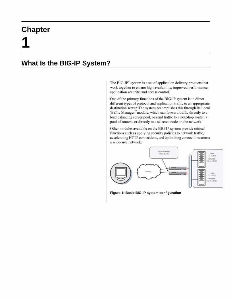
The BIG-IP® system is a set of application delivery products thatwork together to ensure high availability, improved performance,application security, and access control.
One of the primary functions of the BIG-IP system is to directdifferent types of protocol and application traffic to an appropriatedestination server. The system accomplishes this through its LocalTraffic Manager™module, which can forward traffic directly to aload balancing server pool, or send traffic to a next-hop router, apool of routers, or directly to a selected node on the network.
Other modules available on the BIG-IP system provide criticalfunctions such as applying security policies to network traffic,accelerating HTTP connections, and optimizing connections acrossa wide-area network.
Figure 1: Basic BIG-IP system configuration


Chapter
2General Configuration Properties
• TMOS general configuration properties• About general device properties• Updates to the IP geolocation database• About network time protocol (NTP)• About DNS configuration• About local-traffic properties

TMOS general configuration properties
Part of managing the BIG-IP® system involves configuring andmaintaining a set of global system properties.These properties allow you to configure:
• General device features, such as NTP and DNS• General local traffic features, including some global persistence settings• General global traffic features, including load balancing and metric collection
When you configure general device properties, you are affecting the operation of the BIG-IP system as awhole, rather than just one aspect of it. Similarly, when you configure the general properties related to localtraffic or global traffic, you are globally affecting the operation of the local traffic management and globaltraffic management systems.
About general device properties
The BIG-IP® system general device properties that you can view or configure are:
• The host name• The BIG-IP software version number• The number of CPUs available• The number of CPUs that are active
Other BIG-IP system general device properties that you can configure are:
• Network boot• Quiet boot
You can also perform operations such as reboot or force the system into an OFFLINE state, and reload thedefault geolocation data files that the BIG-IP system uses to source the origin of a name resolution request.
Note: Regarding the Always-On Management (AOM) subsystem, AOM now saves the recent contents ofserial output from the host across host reboots, even when no serial console is attached. The contents arewritten to log files on both the AOM and the host, either after a host reboot/power event or at a user'srequest. This feature is disabled by default. To enable the feature, you must open Secure Shell (ssh) andthen manually change and restart the hostconsh script. For more information, see the F5 Networksknowledge base at http://support.f5.com.
Updates to the IP geolocation database
The BIG-IP® system uses an IP geolocation database to determine the origin of a name resolution request.The default database provides geolocation data for IPv4 addresses at the continent, country, state, ISP, andorganization levels. The state-level data is worldwide, and thus includes designations in other countries thatcorrespond to the U.S. state-level in the geolocation hierarchy, for example, provinces in Canada. Thedefault database also provides geolocation data for IPv6 addresses at the continent and country levels.
Note: You can access the ISP and organization-level geolocation data for IPv4 and IPv6 addresses usingthe iRules® whereis command.
22
General Configuration Properties
Tip: If you require geolocation data at the city-level, contact your F5 Networks® sales representative topurchase additional database files.
You can download a monthly update to the IP geolocation database from F5 Networks.
About network time protocol (NTP)
Network Time Protocol (NTP) is a protocol that synchronizes the clocks on a network. Because, by default,DHCP is enabled for the BIG-IP® system, on the first boot, the BIG-IP system contacts your DHCP serverand obtains the IP address of your NTP server. If the DHCP server provides this IP address, the NTP DeviceConfiguration screen displays the NTP server information. If you do not have a DHCP server on yournetwork, or if the DHCP server does not return the IP address of your NTP server, you can manually addthe IP address of the NTP server to the BIG-IP system using the Configuration utility.
About DNS configuration
Domain Name System (DNS) is an industry-standard distributed internet directory service that resolvesdomain names to IP addresses. When you enable DHCP, the system contacts your DHCP server to obtainthe IP addresses of your local DNS servers and the domain names that the system searches to resolve localhost names. If the DHCP server provides this information, the DNS Device Configuration screen displaysthe information in the DNS Lookup Server List and the DNS Search Domain List.
If you do not have a DHCP server on your network, or if the DHCP server does not supply the information,you can manually create the two lists. The DNS Lookup Server List allows BIG-IP® system users to use IPaddresses, host names, or fully-qualified domain names (FQDNs) to access virtual servers, nodes, or othernetwork objects. The DNS Search Domain List allows BIG-IP system to search for local domain lookupsto resolve local host names.
Additionally, you can manually configure the BIND Forwarder Server List that provides DNS resolutionfor servers and other equipment load balanced by the BIG-IP system, that is, for the servers that the BIG-IPsystem uses for DNS proxy services.
Note: To use DNS Proxy services, you must enable the named service.
About local-traffic properties
The BIG-IP® system includes a set of properties that apply globally to the local traffic management system.These properties fall into two main categories: general local-traffic properties, and persistence properties.You can use the Configuration utility to configure and maintain these properties.
23
BIG-IP® TMOS®: Concepts

Chapter
3SSL Certificates for BIG-IP Devices
• SSL Certificates for BIG-IP Devices• Device certificates• Trusted device certificates
SSL Certificates for BIG-IP Devices
In some cases, BIG-IP® systems need to exchange device certificates, that is, Secure Sockets Layer (SSL)certificates and keys used to verify each others’ credentials before exchanging data. For example, multipleBIG-IP systemsmight need to verify credentials before communicatingwith each other to collect performancedata over a wide area network, for global traffic management.
Note: If you are using the device service clustering (DSCTM) feature and want to establish trust amongBIG-IP devices, see the guide titled BIG-IP® Device Service Clustering: Administration. If you are usingSSL certificates to terminate and initiate local SSL traffic, see the guides BIG-IP® Local Traffic Manager™:Concepts and BIG-IP® Local Traffic Manager™: Implementations.
To perform mutual authentication, BIG-IP systems can use either self-signed certificates or CA-signedcertificates:
Self-signed certificatesWhen you install BIG-IP software, the application includes a self-signed SSL certificate. A self-signedcertificate is an authentication mechanism that is created and authenticated by the system on which itresides.
CA-signed certificatesIf your network includes one or more certificate authority (CA) servers, you can replace the self-signedcertificate on each BIG-IP system with a CA-signed certificate, that is, a certificate that is signed by athird party. Authenticating BIG-IP systems using CA-signed certificates is more secure than usingself-signed certificates.
BIG-IP systems on the network use self-signed or CA-signed certificates for these reasons:
To request authenticationA BIG-IP system can send a certificate to another (target) BIG-IP system to request authentication bythat target BIG-IP system. In this context, the certificate is referred to as a device certificate.
To grant authenticationA BIG-IP system can store one or more certificates that it trusts, to check when receiving a devicecertificate from another BIG-IP system during a request for authentication.
Device certificates
When requesting SSL authentication from another system, the BIG-IP® system needs to present its devicecertificate. On the BIG-IP system, a device certificate is an SSL certificate that a BIG-IP system presentsto another device on the network, for authentication purposes. A device certificate can be either a self-signedcertificate or a CA-signed certificate.
Using the Configuration utility, you can view, import, renew, or export a device certificate.
You can also import or export a device key. The properties of a device key are:
• Key type (such as KTYPE_RSA_PRIVATE)• Key size (such as 1024 bits)• Security type, either normal or FIPS (FIPS-enabled systems only)
26
SSL Certificates for BIG-IP Devices

Trusted device certificates
The BIG-IP® system uses a trusted device certificate or a certificate chain to authenticate another system.For example, a BIG-IP system running Global Traffic Manager™ system might send a request to a LocalTraffic Manager™ system. In this case, the Local Traffic Manager system receiving the request checks itstrusted device certificate or certificate chain in its attempt to authenticate the request.
The SSL protocol supports ten levels of authentication:
Level 0Certificates are verified by the system to which they belong. These types of certificates are also knownas self-signed certificates.
Level 1Certificates are authenticated by a Certificate Authority server that is separate from the system.
Levels 2 through 9Certificates are authenticated by additional CA servers, which verify the authenticity of other servers.These multiple levels of authentication are referred to as certificate chains, and allow for a tieredverification system that ensures that only authorized communications occur between servers.
To configure multi-level certificate authentication, you must:
• Import to each BIG-IP system the trusted device certificates that are necessary to authenticatecommunications with other BIG-IP systems.
• Specify the depth of the certificate chain that the BIG-IP system must traverse.
You can view, import, or export a trusted device certificate or certificate chain.
To manage device certificates, log in to the BIG-IP Configuration utility, and on the Main tab, expandSystem, and click Device Certificates.
27
BIG-IP® TMOS®: Concepts

Chapter
4External File Management
• Introduction to external file management• Data group files• About iFiles• External monitor program files• SSL certificate files

Introduction to external file management
You can import certain external files for use by iRules®, or you can import or create SSL certificates. Theexternal files that iRules can use are data group files and iFiles. Using the BIG-IP® Configuration utility,you can manage these external files or SSL certificates from a central location.
Data group files
Using the BIG-IP® Configuration utility, you can import an existing file that contains content that you wantto reference in an iRule. You import this file from another system to the BIG-IP system.
When you import an existing file to the BIG-IP system, you create an external data group, specifying thisinformation:
• The location of the external file that you want to import to the BIG-IP system.• A unique name for the imported file.• The data group type (address, string, or integer).• The separator for each key/value pair specified in the data group (the default value is :=).• A unique name for the data group.
About iFiles
Using the BIG-IP® Configuration utility, you can import an existing file or URL from another system tothe BIG-IP system, with content that you want an iRule to return to a client based on some iRule event.
To use this feature, you first import an existing file or URL to the BIG-IP system and then assign a newname to the file. To import a file with the Configuration utility and assign it a new name, you use the Systemarea of the navigation pane.
External monitor program files
Using the BIG-IP® Configuration utility, you can import an existing external program monitor file to theBIG-IP system, with content that an external monitor can reference.
To use this feature, you first import an existing file from another system to the BIG-IP system and thenassign a new name to the file. To import a file and assign it a new name, log in to the BIG-IP ConfigurationUtility®, and on the Main tab, expand System, and click File Management.
After importing the file, you use the Local Traffic area of the Configuration utility to create a new externalmonitor program based on the imported file.
30
External File Management

SSL certificate files
Using the BIG-IP® Configuration utility, you can import an existing certificate file from another system tothe BIG-IP system, or you can create a new SSL certificate. To import or create an SSL certificate, log into the BIG-IP Configuration utility, and on the Main tab, expand System, and click File Management.
An imported certificate file has these attributes:
• Contents• Common Name• Organization• Expiration date• Partition / Path
Using the Configuration utility, you can view, import, renew, or export a device certificate.
You can also import or export a device key. The properties of a device key are:
• Key type (such as KTYPE_RSA_PRIVATE)• Key size (such as 1024 bits)• Security type, either Normal or FIPS (FIPS-enabled systems only)
There are several types of files that you can import using the File Management screens of the BIG-IPConfiguration utility. These file types are:
• Key files• Certificate files• PKCS 12 (IIS) files• Archive files• Certificate Revocation List (CRL) files
Note: Do not attempt to manage certificates by copying SSL certificate files into the /config/ssl/*directory and then reloading the system configuration. Certificate-related files are not stored in that location.Therefore, you must use the BIG-IP Configuration utility or tmsh to manage certificate files, key files, andCRL files.
31
BIG-IP® TMOS®: Concepts


Chapter
5Platform Properties
• Introduction to platform properties• General properties• Redundant device properties• User administration properties• Administrative account passwords• SSH access configuration
Introduction to platform properties
Part of managing a BIG-IP® system involves configuring and maintaining a certain set of system properties.These properties consist of general platform properties such as the BIG-IP system host name, IP address,and passwords for its system administrative accounts.
General properties
You can configure these general properties for the BIG-IP® system platform:
The management port and TMMThe BIG-IP system has a management port to handle administrative traffic, and TMM switch interfacesto handle application traffic. TMM switch interfaces are those interfaces controlled by the TrafficManagement Microkernel (TMM) service.
Management port configuration
By default, DHCP is disabled for the management port on the BIG-IP system. When enabled, DHCPuses UDP ports 67 and 68. On the first boot, the BIG-IP system contacts your DHCP server and obtainsa lease for an IP address and default route for the management port, and DNS and NTP servers. Youmust then configure other system attributes, such as host name and domain name servers.
When DHCP is disabled, you manually configure the management port by assigning an IP address andnetmask to the port. The IP address that you assign to the management port must be on a differentnetwork than the self IP addresses that you assign to VLANs.
You can use either an IPv4 or an IPv6 address for the management port.
Additionally, if you intend to manage the BIG-IP system from a node on a different subnet of yournetwork, you can specify an IP address for the BIG-IP system to use as a default route to the managementport.
Note: If you do not have a DHCP server on your network, the BIG-IP system assigns a default IPaddress of 192.168.1.245 to the management port of appliances and virtual systems, and192.186.1.246 to the management port of VIPRION® systems.
Host nameEvery BIG-IP system must have a host name that is a fully qualified domain name. An example of ahost name is bigip-02.win.net.
Host IP addressEvery BIG-IP system must have a host IP address. This IP address can be the same as the address thatyou used for the management port, or you can assign a unique address. The default value on the screenfor this setting is Use Management Port IP Address.
Time zoneAnother of the general platform properties that you can specify is the time zone. The many time zonesthat you can choose from are grouped into these categories: Africa, America, Antarctica, Arctic, Asia,Atlantic, Australia, Europe, Indian, and Pacific. You should specify the time zone region that mostclosely represents the location of the BIG-IP system you are configuring.
34
Platform Properties
Redundant device properties
A BIG-IP® system is typically part of a device group that synchronizes configuration data across two ormore BIG-IP devices and provides high availability (failover and connection mirroring).
To ensure that this operates successfully, you assign a device group (to the root folder) to which you wantto synchronize configuration data. All folders and sub-folders in the folder hierarchy inherit this devicegroup as a folder attribute.
You also assign a floating traffic group to the root folder. All folders and sub-folders in the folder hierarchyinherit this traffic group as a folder attribute.
User administration properties
Part of managing platform-related properties is maintaining passwords for the system account. You canalso configure the system to allow certain IP addresses to access the BIG-IP® system through SSH.
Administrative account passwords
When you ran the Setup utility on the BIG-IP® system, you set up some administrative accounts. Specifically,you set up the root and admin accounts. The root and admin accounts are for use by BIG-IP systemadministrators.
Users logging in with the root account have terminal and browser access to the BIG-IP system. By default,users logging in with the admin account have browser-only access to the BIG-IP system. You can use thegeneral screen for platform properties to change the passwords for root and admin accounts on a regularbasis. To change a password, locate the Root Account or Admin Account setting, and in the Passwordfield, type a new password. In the Confirm field, re-type the same password.
SSH access configuration
When you configure SSH access, you enable user access to the BIG-IP® system through SSH. Also, onlythe IP addresses that you specify are allowed access to the system using SSH.
To configure SSH access, locate the SSH Access setting and select the Enabled check box. Then use theSSH IP Allow setting to select either * All Addresses or Specify Range, which allows you to specify arange of addresses for which access is allowed.
35
BIG-IP® TMOS®: Concepts


Chapter
6Archives
• About archives• About saving archives• About archive restoration

About archives
On any BIG-IP® system, you have a set of data that you created when you initially configured the system,using the Setup utility and the Configuration utility or tmsh. This data consists of traffic managementelements such as virtual servers, pools, and profiles. Configuration data also consists of system and networkdefinitions such as interface properties, self IP addresses, VLANs, and more.
Once you have created the configuration data for the BIG-IP system, you can replicate all of this set of datain a separate file. You can then use this replicated data later, for these reasons:
As an archive for disaster recoveryUsing the Archives feature, you can back up the current configuration data, and if necessary, restorethe data at a later time. F5 Networks® recommends that you use this feature to mitigate the potentialloss of BIG-IP system configuration data. To create an archive, you can use the Configuration utility,which stores the configuration data in a special file known as a user configuration set, or UCS file. Youcan then use the UCS file to recover from any loss of data, in the unlikely event that you need to do so.
As a way to propagate data to other systemsUsing the single configuration file feature, you can easily and quickly propagate the exact configurationof the BIG-IP system to other BIG-IP systems. To create a single configuration file, you export theconfiguration data to a special file known as an .scf file. You can then use the .scf file to configureanother system in one simple operation.
Before you replace a version of the BIG-IP system with a newer version, you should always create anarchive, which is a backup copy of the configuration data. This archive is in the form of a user configurationset, or UCS. Then, if you need to recover that data later, you can restore the data from the archive that youcreated.
A UCS contains the following types of BIG-IP system configuration data:
• System-specific configuration files• Product licenses• User accounts and password information• Domain Name Service (DNS) zone files• Installed SSL keys and certificates
Each time you back up the configuration data, the BIG-IP system creates a new file with a .ucs extension.Each UCS file contains various configuration files needed for the BIG-IP system to operate correctly, aswell as the configuration data.
Important: To create, delete, upload, or download an archive, you must have either the Administrator orResource Administrator role assigned to your user account.
About saving archives
By default, the system stores all archives in the directory /var/local/ucs. You can specify a differentlocation, but in this case, the Configuration utility does not display the UCS files when you view the list ofarchives
After you create an archive on the BIG-IP® system, you can download a copy of the UCS file to the systemfrom which you are running the Configuration utility (a secure remote system). This provides an extra levelof protection by preserving the configuration data on a remote system. In the unlikely event that you need
38
Archives

to restore the data, and a BIG-IP system event prevents you from accessing the archive in the BIG-IP systemdirectory in which you saved the archive, you still have a backup copy of the data.
Important: If your configuration data includes SSL keys and certificates, be sure to store the archive filein a secure environment.
About archive restoration
Not only is the /var/local/ucs directory the only location on the BIG-IP® system in which you can savean archive, but it is also the only location on the BIG-IP system from which you can restore an archive.However, if you previously downloaded an archive to a remote system, and a BIG-IP system event preventsyou from accessing the /var/local/ucs directory, you can upload the archive from that remote system.
39
BIG-IP® TMOS®: Concepts


Chapter
7Services
• Managing BIG-IP System Services
Managing BIG-IP System Services
The BIG-IP® system includes a number of services that you can start, stop, or restart using the Configurationutility. This ability to start or stop services from within the Configuration utility is useful when you wantto run only those services that you need to successfully manage network traffic.
The Configuration utility screen for managing services lists the name of each service and its current status.At a minimum, the services that you can stop or start with the Configuration utility are:
ntpdSets and maintains the system time of day.
snmpdReceives and processes SNMP requests, and sends trap notifications. Note that you must stop this servicebefore updating the SNMP v3 file /config/net-snmp/snmpd.conf, which specifies SNMP usernames.
sshdProvides secure remote login between untrusted hosts.
If you have other BIG-IP product modules running on the BIG-IP system, such as Global TrafficManager™,you might see other services listed on the Services screen.
Important: You must have either the Administrator or Resource Administrator user role assigned to youruser account to stop, start, or restart a service.
When you view the list of services available on the BIG-IP system, you can also view current status. In theConfiguration utility, you can see this status in the History column. Examples of status for a service are:Running for 6 days, Running, and down, Not provisioned.
42
Services

Chapter
8Working with Partitions
• About administrative partitions• About partition Common• About the current partition• Object referencing between partitions• Relationship of partitions to user accounts
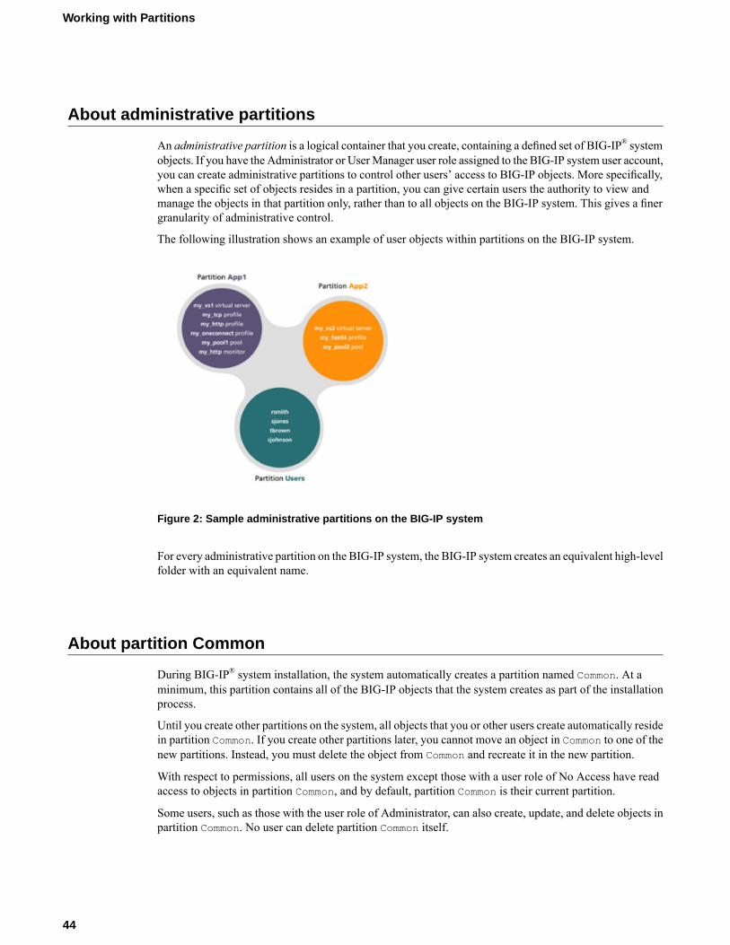
About administrative partitions
An administrative partition is a logical container that you create, containing a defined set of BIG-IP® systemobjects. If you have the Administrator or UserManager user role assigned to the BIG-IP system user account,you can create administrative partitions to control other users’ access to BIG-IP objects. More specifically,when a specific set of objects resides in a partition, you can give certain users the authority to view andmanage the objects in that partition only, rather than to all objects on the BIG-IP system. This gives a finergranularity of administrative control.
The following illustration shows an example of user objects within partitions on the BIG-IP system.
Figure 2: Sample administrative partitions on the BIG-IP system
For every administrative partition on the BIG-IP system, the BIG-IP system creates an equivalent high-levelfolder with an equivalent name.
About partition Common
During BIG-IP® system installation, the system automatically creates a partition named Common. At aminimum, this partition contains all of the BIG-IP objects that the system creates as part of the installationprocess.
Until you create other partitions on the system, all objects that you or other users create automatically residein partition Common. If you create other partitions later, you cannot move an object in Common to one of thenew partitions. Instead, you must delete the object from Common and recreate it in the new partition.
With respect to permissions, all users on the system except those with a user role of No Access have readaccess to objects in partition Common, and by default, partition Common is their current partition.
Some users, such as those with the user role of Administrator, can also create, update, and delete objects inpartition Common. No user can delete partition Common itself.
44
Working with Partitions

About the current partition
The current partition is the specific partition to which the system is currently set for a logged-in user.
A user who has permission to access all partitions can actively select the current partition, that is, the specificpartition he or she wants to view or manage. A user who has permission to access one partition only cannotactively select the current partition; the system sets the current partition for that user when he or she logsin to the system. For example:
• If user rsmith has a role of Manager and has access to all partitions on the system, then before creatingor managing any object on the BIG-IP® system, she must select the partition that she wants to be thecurrent partition. After selecting the current partition, any object that she creates will reside in thatpartition, and she can modify or delete only those objects that reside in the current partition.
• Conversely, if user rsmith has the role of Manager and is granted access to partition A only, then anyobject that she creates while logged into the BIG-IP system resides in partition A. Although she can viewobjects in partition Common, she cannot select Common as her current partition because she has readaccess only for that partition. For user rsmith, partition A is automatically her current partition, andshe cannot change the current partition to create objects in another partition.
Object referencing between partitions
Certain BIG-IP® system objects, such as virtual servers, always reference other objects. Examples of objectsthat a virtual server can reference are pools, profiles, and iRules®. When you create objects, a referencedobject must reside either in the same partition as the object that is referencing it, or in partition Common.
Valid object referencing
This figure shows an example of a valid object-referencing configuration, where a virtual server and thepool it references reside in the same partition (named my_app):
Figure 3: Example of object referencing within a partition
The other valid case in which an object can reference another is when the object resides in one partition,while the object it references resides in partition Common. This figure shows an example of this configuration,where a virtual server in partition my_app references a pool in partition Common:
45
BIG-IP® TMOS®: Concepts
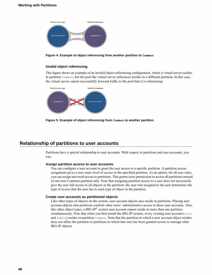
Figure 4: Example of object referencing from another partition to Common
Invalid object referencing
This figure shows an example of an invalid object-referencing configuration, where a virtual server residesin partition Common, but the pool the virtual server references resides in a different partition. In this case,the virtual server cannot successfully forward traffic to the pool that it is referencing:
Figure 5: Example of object referencing from Common to another partition
Relationship of partitions to user accounts
Partitions have a special relationship to user accounts. With respect to partitions and user accounts, youcan:
Assign partition access to user accountsYou can configure a user account to grant the user access to a specific partition. A partition accessassignment gives a user some level of access to the specified partition. As an option, for all user roles,you can assign universal access to partitions. This grants users permission to access all partitions insteadof one non-Common partition only. Note that assigning partition access to a user does not necessarilygive the user full access to all objects in the partition; the user role assigned to the user determines thetype of access that the user has to each type of object in the partition.
Create user accounts as partitioned objectsLike other types of objects on the system, user account objects also reside in partitions. Placing useraccount objects into partitions controls other users’ administrative access to those user accounts. Also,like other object types, a BIG-IP® system user account cannot reside in more than one partitionsimultaneously. Note that when you first install the BIG-IP system, every existing user account (rootand admin) resides in partition Common. Note that the partition in which a user account object residesdoes not affect the partition or partitions to which that user has been granted access to manage otherBIG-IP objects
46
Working with Partitions

Figure 6: Relationship of partitions to user accounts
47
BIG-IP® TMOS®: Concepts


Chapter
9Working with Folders
• About folders on the BIG-IP system• Relationship of folders to partitions• Folder and object naming• Object referencing between folders

About folders on the BIG-IP system
At the most basic level, a folder is a container for BIG-IP® configuration objects and files on a BIG-IPdevice. Virtual servers, pools, and self IP addresses are examples of objects that reside in folders on thesystem. Folders resemble standard directories, in that the system includes a root folder (represented by the/ symbol) that is the parent for other folders on the system.
A folder can contain other folders.
One of the important ways that you can use folders is to set up full or granular synchronization and failoverof BIG-IP configuration data in a device group. You can synchronize and fail over all configuration dataon a BIG-IP device, or you can synchronize and fail over objects within a specific folder only.
Relationship of folders to partitions
For each partition on the BIG-IP® system, there is an equivalent high-level folder. For example, for partitionCommon, there is a corresponding high-level folder named /Common. This close association of administrativepartitions to folders means that when you use the BIG-IP Configuration utility to create objects on a BIG-IPdevice, the system puts those objects in the current partition, in a folder that you choose. Examples of BIG-IPobjects that reside in folders are virtual servers, pools, and self IP addresses.
If you create another administrative partition, such as partition App_A, the BIG-IP system automaticallycreates a high-level folder named /App_A. You can then create BIG-IP configuration objects that pertainto application A by changing the current partition to App_A and then either creating the objects in folder/App, or creating a sub-folder within /App_A and then navigating to that sub-folder.
Folder and object naming
The folder in which an object resides automatically becomes part of the object name. For example, if youcreate a pool in partition Common, in folder /Common, and then name the pool my_pool, the full name ofthe pool on the system is /Common/my_pool. If you create a pool in partition App_A, in folder /App_A,then the full name of the pool is /App_A/my_pool.
Object referencing between folders
When you create two BIG-IP® objects in separate folders, where one object references the other, thereferenced object must reside in /Common or a sub-folder of /Common.
For example, if you create a virtual server in folder /App_B, and the virtual server references a load balancingpool, the pool object must reside in folder /Common or in a sub-folder of /Common.
50
Working with Folders

Chapter
10Users
• Introduction to user account management• User account types• Administrative partitions• What are user roles?• Default user roles• Effect of user roles on objects within
partitions• Local user account management• Admin account configuration• About secure password policy configuration• User authentication lockout• Local user account creation• Local user account view• Local user account modification• Delete local user accounts• Remote user account management• Remote user-account server specification• Authorization for remote accounts• Default remote-user authorization• Authorization for an individual user account• Authorization for groups of user accounts• Partition access• About viewing remote user accounts• About auditing user access to the system

Introduction to user account management
An important part of managing the BIG-IP® system is creating and managing user accounts for BIG-IPsystem administrators. By creating user accounts for system administrators, you provide additional layersof security. User accounts ensure that the system:
• Verifies the identity of users logging into the system (authentication)• Controls user access to system resources (authorization)
To enable user authentication and authorization, you assign passwords and user roles to your user accounts.Passwords allow you to authenticate your users when they attempt to log in to the BIG-IP system. Userroles allow you to control user access to BIG-IP system resources.
You can create and store BIG-IP administrative accounts either locally on the BIG-IP system, or remotelyon a separate authentication server. If you want your user accounts to reside locally on the BIG-IP system,you create those user accounts on the BIG-IP system and assign user roles to them.
If you want your user accounts to reside remotely on a separate authentication server, you do not use theBIG-IP system to create the accounts. Instead, you use the mechanism provided by the server vendor, andyou use the BIG-IP system strictly to assign user roles to those remote accounts and to maintain those userrole assignments over time. The types of servers that you can use to remotely store BIG-IP system useraccounts are:
• Lightweight Directory Access Protocol (LDAP) servers• Active Directory servers• Remote Authentication Dial-in User Service (RADIUS) servers
User account types
There are two types of user accounts on the BIG-IP® system: The system maintenance account and a set ofstandard user accounts.
The system maintenance accountThe system maintenance account is a user account that you maintain using the Setup utility. The nameof the system maintenance account is root. This account resides locally on the BIG-IP system andgrants full access to BIG-IP system resources. You configure and maintain this account using the Setuputility and the Configuration utility, respectively.
Standard user accountsStandard user accounts are user accounts that you create for other BIG-IP system administrators to use.Standard user accounts can reside either locally on the BIG-IP system, or remotely on a remoteauthentication server. You create and maintain these accounts using the browser-based Configurationutility or the command line interface. Creating standard user accounts allows you to assign various userroles to those accounts as a way to control system administrator access to BIG-IP system resources. Aspecial standard user account is the admin account, which automatically exists on any BIG-IP system.
Note: Excluding the admin account, the entire set of standard user accounts that you create for BIG-IPsystem administrators must reside either locally on the BIG-IP system, or remotely on another type ofauthentication server.
52
Users
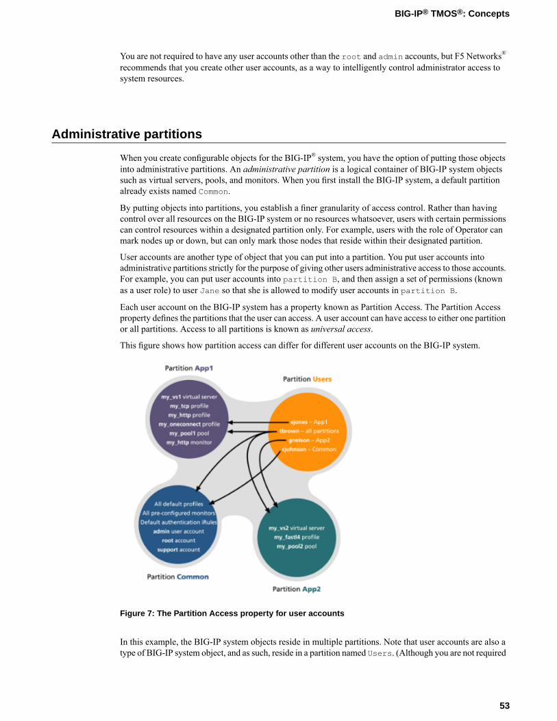
You are not required to have any user accounts other than the root and admin accounts, but F5 Networks®
recommends that you create other user accounts, as a way to intelligently control administrator access tosystem resources.
Administrative partitions
When you create configurable objects for the BIG-IP® system, you have the option of putting those objectsinto administrative partitions. An administrative partition is a logical container of BIG-IP system objectssuch as virtual servers, pools, and monitors. When you first install the BIG-IP system, a default partitionalready exists named Common.
By putting objects into partitions, you establish a finer granularity of access control. Rather than havingcontrol over all resources on the BIG-IP system or no resources whatsoever, users with certain permissionscan control resources within a designated partition only. For example, users with the role of Operator canmark nodes up or down, but can only mark those nodes that reside within their designated partition.
User accounts are another type of object that you can put into a partition. You put user accounts intoadministrative partitions strictly for the purpose of giving other users administrative access to those accounts.For example, you can put user accounts into partition B, and then assign a set of permissions (knownas a user role) to user Jane so that she is allowed to modify user accounts in partition B.
Each user account on the BIG-IP system has a property known as Partition Access. The Partition Accessproperty defines the partitions that the user can access. A user account can have access to either one partitionor all partitions. Access to all partitions is known as universal access.
This figure shows how partition access can differ for different user accounts on the BIG-IP system.
Figure 7: The Partition Access property for user accounts
In this example, the BIG-IP system objects reside in multiple partitions. Note that user accounts are also atype of BIG-IP system object, and as such, reside in a partition named Users. (Although you are not required
53
BIG-IP® TMOS®: Concepts
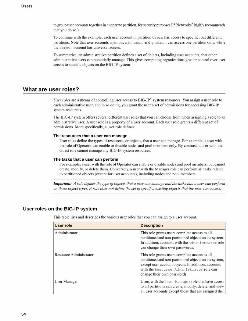
to group user accounts together in a separate partition, for security purposes F5Networks® highly recommendsthat you do so.)
To continue with the example, each user account in partition Users has access to specific, but different,partitions. Note that user accounts sjones, cjohnson, and gnelson can access one partition only, whilethe tbrown account has universal access.
To summarize, an administrative partition defines a set of objects, including user accounts, that otheradministrative users can potentially manage. This gives computing organizations greater control over useraccess to specific objects on the BIG-IP system.
What are user roles?
User roles are a means of controlling user access to BIG-IP® system resources. You assign a user role toeach administrative user, and in so doing, you grant the user a set of permissions for accessing BIG-IPsystem resources.
The BIG-IP system offers several different user roles that you can choose from when assigning a role to anadministrative user. A user role is a property of a user account. Each user role grants a different set ofpermissions. More specifically, a user role defines:
The resources that a user can manageUser roles define the types of resources, or objects, that a user can manage. For example, a user withthe role of Operator can enable or disable nodes and pool members only. By contrast, a user with theGuest role cannot manage any BIG-IP system resources.
The tasks that a user can performFor example, a user with the role of Operator can enable or disable nodes and pool members, but cannotcreate, modify, or delete them. Conversely, a user with the Manager role can perform all tasks relatedto partitioned objects (except for user accounts), including nodes and pool members.
Important: A role defines the type of objects that a user can manage and the tasks that a user can performon those object types. A role does not define the set of specific, existing objects that the user can access.
User roles on the BIG-IP system
This table lists and describes the various user roles that you can assign to a user account.
DescriptionUser role
This role grants users complete access to allpartitioned and non-partitioned objects on the system.
Administrator
In addition, accounts with the Administrator rolecan change their own passwords.
This role grants users complete access to allpartitioned and non-partitioned objects on the system,
Resource Administrator
except user account objects. In addition, accountswith the Resource Administrator role canchange their own passwords.
Users with the User Manager role that have accessto all partitions can create, modify, delete, and view
User Manager
all user accounts except those that are assigned the
54
Users

DescriptionUser roleAdministrator role, or the User Manager rolewith different partition access. Accounts with theUser Manager role that have access to all partitionscan also change their own passwords.
Users with the User Manager role that have accessonly to a single partition can create, modify, delete,and view only those user accounts that are in thatpartition and that have access to that partition only.For example, if your user account has a UserManager role and has access to Partition A only, thenyou can manage only those user accounts that bothreside in and have access to Partition A only.
User accounts with the User Manager role canchange their own passwords.
This role grants users permission to create, modify,and delete virtual servers, pools, pool members,
Manager
nodes, custom profiles, custom monitors, andiRules®®. These users can view all objects on thesystem and change their own passwords.
This role grants users permission to manage devicecertificates and keys, as well as perform FederalInformation Processing Standard (FIPS) operations.
Certificate Manager
This role grants users permission to create, modify,and delete iRules. Users with this role cannot affect
iRule Manager
the way that an iRule is deployed. For example, auser with this role can create an iRule but cannotassign it to a virtual server or move the iRule fromone virtual server to another. A user with this rolecan be assigned universal access to administrativepartitions.
This role grants users permission to modify nodes,pools, pool members, and monitors. These users can
Application Editor
view all objects on the system and change their ownpasswords.
This role allows users to view, create, modify, anddelete all WebAccelerator™™ policy objects in all
Acceleration Policy Editor
administrative partitions. Users can also view, create,update, and delete Web Acceleration profiles.
This role grants a user access to all ApplicationSecurity Manager™security policy objects on the
Application Security Administrator
BIG-IP system. These users have read-onlypermission for these profile types: HTTP, FTP, andSMTP. These users have no access to other LTMobjects, nor to any TMOS objects. They can,however, change their own passwords. With respectto security policy objects, this role is similar to theAdministrator role. You can assign this role onlywhen the BIG-IP system includes the BIG-IPApplication Security Manager component.
55
BIG-IP® TMOS®: Concepts
DescriptionUser role
This role allows a user to configure or view mostparts of the Application Security Manager
Web Application Security Editor
component, in a specified administrative partitiononly. Specifically, these users have limited access toLTM objects, namely read-only permission for theseprofile types: HTTP, FTP, and SMTP.
These users have no access to other LTM objects,nor to any TMOS objects. They can, however,change their own passwords.
You can assign this role only when the BIG-IPsystem includes the Application Security Managercomponent.
This role grants users permission to enable or disablenodes and pool members. These users can view allobjects and change their own passwords.
Operator
This role grants users permission to view allconfiguration data on the system, including logs and
Auditor
archives. Users with this role cannot create, modify,or delete any data, nor can they view SSL keys oruser passwords.
This role grants users permission to view all objectson the system except for sensitive data such as logs
Guest
and archives. Users with this role can change theirown passwords.
This role prevents users from accessing the system.No Access
Default user roles
The BIG-IP® system automatically assigns a user role to an account when you create that account. The userrole that the system assigns to a user account by default depends on the type of account:
root and admin accountsThe BIG-IP system automatically assigns the Administrator user role to the system maintenance rootaccount and the admin account. You cannot change this user-role assignment. Thus, any user whosuccessfully logs into the BIG-IP system using the root or admin account has full access to systemresources and can perform all administrative tasks.
Other user accountsThe BIG-IP system automatically assigns the No Access user role to all standard user accounts otherthan the root and admin accounts. If the user account you are using has the Administrator role assignedto it, you are allowed to change another account’s user role from the default No Access role to any otheruser role, including Administrator. For remote user accounts, if you know that most of your administrativeusers need some amount of access to BIG-IP system resources, you can configure the BIG-IP systemto use a role other than No Access as the default user role.
56
Users
Effect of user roles on objects within partitions
A user role defines the access level that a user has for each object in the user’s assigned partition. An accesslevel refers to the type of task that a user can perform on an object. Possible access levels are:
WriteGrants full access: that is, the ability to create, modify, enable and disable, and delete an object.
UpdateGrants the ability to modify, enable, and disable an object.
Enable/disableGrants the ability to enable or disable an object.
ReadGrants the ability to view an object.
Local user account management
Managing local user accounts refers to the tasks of creating, viewing, modifying, and deleting user accountsthat reside on the BIG-IP® system, using the browser-based Configuration utility.
The Configuration utility stores local user accounts (including user names, passwords, and user roles) in alocal user-account database. When a user logs in to the BIG-IP system using one of these locally-storedaccounts, the BIG-IP system checks the account to determine the user role assigned to that user account.
Important: Only users with the role of Administrator or User Manager can create and manage local useraccounts. However, users with any role can change their own passwords. Also, if a user with a local useraccount is logged in to the BIG-IP system, and you subsequently switch the system from local authenticationto remote authentication, the local user remains authenticated until the user’s login session terminates.
Admin account configuration
A user account called admin resides on every BIG-IP® system. Although the BIG-IP system creates thisaccount automatically, you must still assign a password to the account before you can use it. To initiallyset the password for the admin account, you must run the Setup utility. To change its password later, youuse the Configuration utility’s Users screens.
The admin account resides in the local user account database on the BIG-IP system. By default, the BIG-IPsystem assigns the Administrator user role, which gives the user of this account full access to all BIG-IPsystem resources. You cannot change the user role on this account.
57
BIG-IP® TMOS®: Concepts
About secure password policy configuration
The BIG-IP® system includes an optional administrative feature: a security policy for creating passwordsfor local BIG-IP system user accounts. A secure password policy ensures that BIG-IP system users whohave local user accounts create and maintain passwords that are as secure as possible.
The secure password policy feature includes two distinct types of password restrictions:
Enforcement restrictionsThese are, specifically, character restrictions that you can enable or disable. They consist of the minimumpassword length and the required character types (numeric, uppercase, lowercase, and other kinds ofcharacters). When enabled, the BIG-IP system never enforces restrictions on user accounts that havethe Administrator role assigned to them. Consequently, a user with Administrator permissions does notneed to adhere to these restrictions when either changing his or her own password, or changing thepasswords of other user accounts.
Policy restrictionsThese restrictions represent the minimum and maximum lengths of time that passwords can be in effect.Also included in this type of policy restriction are the number of days prior to password expiration thatusers are warned, and the number of previous passwords that the BIG-IP system should store, to preventusers from re-using former passwords. These restrictions are always enabled, although using the defaultvalues provides a minimal amount of restriction.
Note: The value of theMaximum Duration setting determines when users receive warning messages tochange their passwords. If you change the value of this setting, any subsequent warning messages that usersreceive indicate the previous maximum duration value, rather than the new value. Once a user changes thepassword, however, subsequent reminder messages show the new value.
The password policy feature affects passwords for local user accounts only. Passwords for remotely-storeduser accounts are not subject to this local password policy, but might be subject to a separate passwordpolicy defined on the remote system.
Important: You must have the user role of Administrator assigned to your account to configure this feature.
Configuration settings for a secure password policy
This table lists and describes the settings for a password policy.
Default valueDescriptionSetting
DisabledEnables or disables characterrestrictions, that is, a policy for
Secure Password Enforcements
minimum password length andrequired characters. When youenable this setting, theConfiguration utility displays theMinimum Length and RequiredCharacters settings.
6Specifies the minimum number ofcharacters required for a password,
Minimum Length
and the allowed range of values is6 to 255. This setting appears only
58
Users
Default valueDescriptionSettingwhen you enable the SecurePassword Enforcement setting.
Important: Any user account withtheAdministrator role assigned toit (including the root and adminaccounts) is not subject to therestrictions imposed by this setting.
0Specifies the number of numeric,uppercase, lowercase, and other
Required Characters
characters required for a password.The allowed range of values is 0to 127. This setting appears onlywhen you enable the SecurePassword Enforcement setting.
Important: Important: Any useraccount with the Administratorrole assigned to it (including theroot and admin accounts) is notsubject to the restrictions imposedby this setting.
0Specifies, for each user account,the number of former passwords
Password Memory
that the BIG-IP system retains toprevent the user from re-using arecent password. The range ofallowed values is 0 to 127.
0Specifies the minimum number ofdays before a user can change a
Minimum Duration
password. The range of allowedvalues is 0 to 255.
99999Specifies themaximumnumber ofdays that a user's password can be
Maximum Duration
valid. The range of allowed valuesis 1 to 99999. This setting appliesto all user accounts.
7Specifies the number of days priorto password expiration that the
Expiration Warning
system sends a warning messageto a user. The range of allowedvalues is 1 to 255. This settingapplies to all user accounts.
0Denies access to a user after thespecified number of failed
Maximum Login Failures
authentication attempts. Theadministrator can then reset thelock to re-enable access for theuser.
59
BIG-IP® TMOS®: Concepts

User authentication lockout
You can deny access to a user after a specified number of failed authentication attempts. You can then resetthe lock to re-enable access for the user.
To set the maximum number of failures before user lockout, use the BIG-IP® Configuration utility to locatethe Users screen, and then navigate to the Authentication screen. You can then specify a value for theMaximum Login Failures setting.
If a user becomes locked out, you can use the Unlock button on the User List screen to unlock the user.
Local user account creation
When you create a local user account, you must give the account a name and a password. You must alsoset the user role, either by retaining the default user role or by assigning a new one. The default user rolefor local, non-system maintenance accounts is No Access.
Only users who have been granted the Administrator or User Manager role can create user accounts. If theuser role assigned to your account is Administrator, you can create a user account in any partition on thesystem. If the user role assigned to your account is User Manager, you can create a user account in anypartition to which you have access.
Note: User accounts on the BIG-IP® system are case-sensitive. Thus, the system treats user accounts suchas JONES and Jones as two separate user accounts. Note, however, that certain user names, such as admin,are reserved, and are therefore exempt from case-sensitivity. For example, you cannot create a user accountnamed Admin, aDmin, or ADMIN.
Properties of a local BIG-IP system user account
This table lists and describes the properties that define a local BIG-IP user account.
Default ValueDescriptionProperty
No default valueSpecifies the name of the useraccount. The BIG-IP system is
User Name
case-sensitive, which means thatnames such as JONES and Jonesare treated as separate useraccounts.
No default valueWhen viewing the properties of anexisting user account, displays the
Partition
name of the partition in which theuser account resides. Allpartitionable BIG-IP systemobjects (including user accountobjects) have the Partitionproperty. Note that you cannot editthe value of this setting.
60
Users
Default ValueDescriptionProperty
No default valueSpecifies a password that the userwill use to log in to the BIG-IPsystem.
Password
No AccessSpecifies the user role that youwant to assign to the user account.
Role
AllSpecifies the partition to which theuser has access when logged on to
Partition Access
the BIG-IP system. If you havepermission to do so, you can assignthis value to a new user account,or change this value on an existinguser account. This setting appearsonly when the user role for theaccount is not Administrator.(Accounts with theAdministratorrole always have universalpartition access, that is, access toall partitions.)
DisabledSpecifies the level of access to theBIG-IP system command line
Terminal Access
interface. Possible values are:Disabled and Advanced shell.Users with the Administrator orResource Administrator roleassigned to their accounts can haveadvanced shell access, that is,permission to use all BIG-IPsystem command line utilities, aswell as any Linux commands.
Local user account view
Using the Configuration utility, you can easily display a list of existing local user accounts and view theproperties of an individual account. Only users who have been granted the Administrator or User Managerroles can view the settings of other user accounts.
If the user role assigned to your account is Administrator, you can view any user account on the BIG-IP®
system, in any partition. If the user role assigned to your account is User Manager, you can view any useraccount in any partition to which you have access on the BIG-IP system.
To summarize, depending on their own partition access, users with a User Manager role can do some or allof the following:
• Change another user’s password• Change another user’s user role• Change the partition in which the user can access objects (applies only to users who have both a User
Manager role and access to all partitions)• Enable or disable terminal access
61
BIG-IP® TMOS®: Concepts
Local user account modification
You use the Configuration utility to modify the properties of any existing local user account, other than theroot account. When modifying user accounts, consider the following:
• Only users who have been granted either the Administrator or User Manager role can modify useraccounts other than their own account.
• A user with the User Manager role can modify only those accounts that reside in the partition to whichthat user has access. For example, if user nelson has a User Manager role and has access to partitionB only, he can modify only those user accounts that reside in partition B. Even in this case, however, foruser accounts in partition B, user nelson cannot modify a user’s Partition Access property. If, however,user nelson has a User Manager role and has access to all partitions, he can modify all user accountson the system. This includes changing another user’s Partition Access property.
• Users with any role but No Access can modify their own user accounts to change the password. Theseusers cannot modify any other properties of their own user accounts.
Note: Note: When a user changes his own password, the system automatically logs the user off of theConfiguration utility. The system then requires the user to use the new password for subsequent logins.This behavior applies even when the new password matches the old password.
• Users with the role of User Manager can modify all of the properties of their own user accounts, excepttheir user role and partition access.
If you have an Administrator user role, you can also change some properties of the root account. Specifically,you can change the password of the root account, and you can enable or disable access to the BIG-IP®
system through SSH.
Warning: The Administrator user role provides access to the BIG-IP system prompt. If a user with theAdministrator user role is currently logged on to the system, and you change the user role to a role otherthan Administrator or Resource Administrator, the user can still run commands at the BIG-IP system promptuntil he or she logs off of the system.
Delete local user accounts
If the account you are using has the Administrator or User Manager user role, you can delete other localuser accounts. A user with the Administrator role can delete any user account on the BIG-IP® system in anypartition. A user with the User Manager role can delete user accounts on the BIG-IP system in only thosepartitions to which she has access.
When you delete a local user account, you remove it permanently from the local user-account database onthe BIG-IP system.
Note: You cannot delete the admin user account, nor can you delete the user account with which you arelogged in.
Warning: The Administrator user role provides access to the BIG-IP system prompt. If a user with theAdministrator user role is currently logged in to the system and you delete the user account, the user canstill run commands at the BIG-IP system prompt until he or she logs off of the system.
62
Users
Remote user account management
Rather than store user accounts locally on the BIG-IP® system, you can store them on a remote authenticationserver. In this case, you create all of your standard user accounts (including user names and passwords) onthat remote server, using the mechanism supplied by that server’s vendor.
Once you have created each user account on the remote server, you can then use the BIG-IP system to assignauthorization properties (user role, partition access, and terminal access) for each account, for the purposeof controlling user access to BIG-IP system resources.
Important: You can assign authorization properties to remotely-stored user accounts on a group basis.You can then use the single configuration file (SCF) feature to propagate those properties to other BIG-IPdevices on the network.
The Configuration utility stores all local and remote access control information in the BIG-IP system’s localuser-account database. When a user whose account information is stored remotely logs into the BIG-IPsystem and is granted authentication, the BIG-IP system then checks its local database to determine theaccess control properties that you assigned to that user.
Note: The Configuration utility refers to remote user accounts as external users. An external user is anyuser account that is stored on a remote authentication server.
Important: Only users with the role of Administrator can manage user roles for remote user accounts.Also, if a user with a local user account is logged on to the BIG-IP system, and you subsequently switchthe system from local authentication to remote authentication, the local user remains authenticated untilthe user’s login session terminates.
Remote user-account server specification
One of the tasks you perform with the Configuration utility is to specify the type of remote user-accountserver that currently stores your remote user accounts. The available server types that you can specify are:
• Active Directory or Lightweight Directory Access Protocol (LDAP)• Remote Authentication Dial-In User Service (RADIUS)• Terminal Access Controller Access-Control System Plus (TACACS+)
When you specify the type of remote server, you can also configure some server settings. For example, youcan specify the user role you would like the BIG-IP® system to assign to a remote account if you do notexplicitly assign one.
Once you have configured the remote server, if you want any of the remote accounts to have a non-defaultuser role, you can explicitly assign a user role to those accounts.
If the remote authentication server is an Active Directory or LDAP server and is set up to authenticate SSLtraffic, there is an additional feature that you can enable. You can configure the BIG-IP system to performthe server-side SSL handshake that the remote server would normally perform when authenticating clienttraffic. In this case, there are some preliminary steps you must perform to prepare for remote authenticationusing SSL.
63
BIG-IP® TMOS®: Concepts
Authorization for remote accounts
You create BIG-IP® system user accounts on your remote server using the mechanism provided by thevendor of your remote server. Then you use the Configuration utility to specify the remote authenticationserver that you are using to store those BIG-IP system user accounts. (Valid remote authentication serversfor storing BIG-IP system user accounts are Active Directory, LDAP, RADIUS, and TACACS+.)
Once you have used the Configuration utility to specify the remote authentication server, you can configureauthorization properties for the remote BIG-IP system user accounts. Specifically, you can do the following:
• Assign a single set of default authorization properties to all remotely-stored user accounts.• Assign unique authorization properties to an individual remote user account by creating a corresponding
local user account, with the same user name, on the BIG-IP system and assigning access-control propertiesto it.
• Change the authorization properties of an individual remote account.• Assign access-control properties on a group basis (that is, based on groups of users defined on a remote
authentication server).
Default remote-user authorization
The Authentication screen that you used to specify the type of remote authentication server also includessome default authorization values (for the Role, Partition Access, and Terminal Access settings). Therefore,if you do not explicitly configure these authorization settings for an individual BIG-IP® system user account,the BIG-IP system assigns the default values to that account. This ensures that all remote user accountshave valid authorization settings assigned to them.
The default values for the Role, Partition Access, and Terminal Access settings are as follows:
• Role--No Access• Partition Access--All• Terminal Access--Disabled
When you use these default values for a user account, the user account appears in the list of BIG-IP useraccounts as Other External Users.
You can change the values that the BIG-IP system automatically uses as the default values for theRole,Partition Access, and Terminal Access settings.
To change the default authorization properties for remote user accounts, you configure the Role, PartitionAccess, and Terminal Access settings on the same Authentication screen that you used to specify the typeof remote authentication server you are using.
Important: For the Other External Users user account, you can modify the Role, Partition Access,and Terminal Access settings only when your current partition on the BIG-IP system is set to Common. Ifyou attempt to modify these settings when your current partition is other than Common, the system displaysan error message.
Note that you can sometimes inadvertently affect your own user account, if the BIG-IP system is configuredto perform remote user authentication, and you or another system administrator changes the default role orpartition assigned to all external user accounts:
• If you log on to the BIG-IP system using one of these remotely-authenticated Administrator accounts,and you or another Administrator user modifies the default role of all external accounts fromAdministrator
64
Users

to a lesser role, the system modifies the user role of your own account to the lesser role. However, thechange to your own account does not actually occur until you log off and log on again to the BIG-IPsystem, thus allowing you to complete any tasks you initiated that still require the Administrator role.
• Similarly, your user account can be affected if the BIG-IP system is configured to perform remote userauthentication, and the default partition assigned to all external user accounts is a specific partition. Inthis case, if you are logged on to the BIG-IP system through the command line using one of theremotely-authenticated accounts, and another user who is logged on through the Configuration utilitymodifies the default partition for external users, the BIG-IP system immediately logs you off when youattempt to issue another command.
Important: If a BIG-IP system administrator changes the user role or partition assignment (or both) forany remote user account, the BIG-IP system logs off all users immediately. (A remote user account in thiscase refers to Other External Users.)
Authorization for an individual user account
You do not use the Configuration utility to create remote user accounts (user name and password) for theBIG-IP® system. Instead, you create those user accounts on the remote server, using the mechanism providedby the remote server vendor. For authorization (access control) data, however, if you have the Administratorrole assigned to your own user account, you can use the Configuration utility to explicitly assign accesscontrol properties to existing remote accounts.
Note: The BIG-IP system automatically assigns a default user role and other authorization properties toan existing remote account if you do not explicitly do so.
Remote user account names do not appear in the Configuration utility on the User List screen. Therefore,to assign non-default authorization properties to an existing remote account, you must simulate the creationof a new account on the BIG-IP system, configuring the User Name setting with the precise name of theexisting remote account. You then configure the other properties on the Create screen as well. In this way,you assign authorization properties to an existing remote user account.
Use these procedures to assign non-default authorization properties to, or delete them from an existingremote user account.
Changing authorization for an individual user account
Sometimes you might want to change the user role, partition access, and terminal access that you previouslyassigned to a remote account. To do so, you must change the properties of that account by clicking theaccount name on the User List screen. Only those remote user accounts to which you have explicitly assigneda user role appear in the list of user accounts.
Remote user accounts that simply inherit the default user role (configured when you specified the remoteauthentication server) appear in the list of remote user accounts under the name Other External Users.
Deleting authorization for an individual user account
When you use the Configuration utility to delete a remote user account, you are not actually deleting theaccount from the remote server. Instead, you are changing the values of the user’s authorization propertiesback to the default values.
65
BIG-IP® TMOS®: Concepts

Authorization for groups of user accounts
If you want to assign the same non-default access control properties to a group of remotely-stored useraccounts, you can use the remote role groups feature. This feature stores all access control information ona group-wide basis for remotely-stored user accounts.
After using the remote role groups feature, you can propagate that access-control information to all BIG-IP®
devices on the network, using the single configuration file (SCF) feature. The remote role groups feature,combined with the SCF feature, removes the need to manually assign access control properties to eachindividual BIG-IP user within a group, on each BIG-IP device on your network.
You can access the remote role groups feature by logging into the BIG-IP® Configuration utility andnavigating to System > Users > Remote Role Groups.
Values for the remote role variable
This table lists the allowed values for a variable that you use for defining a role for a remotely-stored useraccount.
ValueUser Role
0Administrator
ResourceAdministrator
40User Manager
100Manager
300Application Editor
400Operator
700Guest
800Application SecurityPolicy Editor
900No Access
Partition access
When you initially configure a remote server for authentication of BIG-IP® system users, all remote useraccounts have access to the Common partition. If you want a specific remote account to have access to apartition other than Common, you can specify a different partition when you configure the authorizationproperties for that account. Remote accounts that have the Administrator user role assigned to themautomatically have full access to all partitions on the BIG-IP system.
66
Users

About viewing remote user accounts
Using the Configuration utility, you can display a list of those remote user accounts to which you explicitlyassigned a non-default user role. If a remote user account has the default role assigned to it, you cannot seethat account in the list of remote user accounts.
Any users who have access to a partition in which remote accounts reside can view a list of remote useraccounts.
About auditing user access to the system
The BIG-IP® system generates a log message whenever a user or an application attempts to log in to or logout of the system. The system logs both successful and unsuccessful login attempts. The system stores theselog messages in the /var/log/secure file.
When the system logs an authentication message in the /var/log/secure file, the message can containthe following types of information:
• The connecting user's ID• The IP address or host name of the user's interface• The time of each login attempt• Successful login attempts for command line interface sessions only• Failed login attempts for command line interface, Configuration utility, and iControl® sessions• The time of the logout for command line interface sessions only
This is an example of log messages for both successful and failed login attempts made by user jsmith.
May 10 16:25:25 jsmith-dev sshd[13272]: pam_audit: user: jsmith(jsmith) from: /dev/pts/10 atjsmith-dev attempts: 1 in:[Thu May 10 16:25:23 2007 ] out: [Thu May 10 16:25:25 2007 ]May 10 16:14:56 jsmith-dev sshd[716]: pam_audit: User jsmith from ssh at jsmith-dev failed tologin after 1 attempts(start: [Thu May 10 16:14:53 2007 ] end: [Thu May 10 16:14:56 2007 ]).
67
BIG-IP® TMOS®: Concepts

Chapter
11Logging
• BIG-IP system logging overview• Types of log messages• Existing Syslog configurations• Remote storage of log messages• Local storage of log messages• Log level settings for BIG-IP system events• About local Syslog logging• Logging system events• Logging BIG-IP system configuration
changes (audit logging)• Code expansion in Syslog log messages• About enabling and disabling auditing logging• About remote logging using Syslog-ng

BIG-IP system logging overview
Viewing and managing log messages is an important part of managing traffic on a network and maintaininga BIG-IP® system. Log messages inform you on a regular basis of the events that are happening on thesystem.
You can log events either locally on the BIG-IP system or remotely, using The BIG-IP system’s high-speedlogging mechanism. The recommended way to store logs is on a pool of remote logging servers.
For local logging, the high-speed logging mechanism stores the logs in either the Syslog or the MySQLdatabase on the BIG-IP system, depending on a destination that you define. For remote logging, the high-speedlogging mechanism sends log messages to a pool of logging servers that you define.
Types of log messages
Examples of the types of messages that the high-speed logging mechanism can log are:
• BIG-IP® system-level events• DNS events (for local traffic and global traffic)• Network Firewall events• Protocol Security events• Carrier-grade NAT (CGNAT) events• Denial of Service (DoS) protection events
Existing Syslog configurations
If you previously configured the BIG-IP® system to log messages locally using the Syslog utility or remotelyusing the Syslog-ng utility, you can continue doing so with your current logging configuration, withoutconfiguring high-speed logging.
Alternatively, however, you can configure local Syslog logging using the high-speed logging mechanism,which is the recommended Syslog configuration. By configuring Syslog using high-speed logging, you caneasily switch logging utilities in the future as needs change, without having to perform significantre-configuration.
Remote storage of log messages
The way that you set up remote, high-speed logging is by first defining a pool of logging servers, and thencreating an unformatted, remote high-speed log destination that references the pool. If you are using ArcSight,Splunk, or Remote Syslog logging servers that require a formatted destination, you can also create a formattedlog destination for one of those server types. Once those objects are set up, you create a publisher and acustom logging profile pertaining to the type of message you want to log. You then assign the loggingprofile to a relevant virtual server, and the profile, in turn, references the publisher.
70
Logging
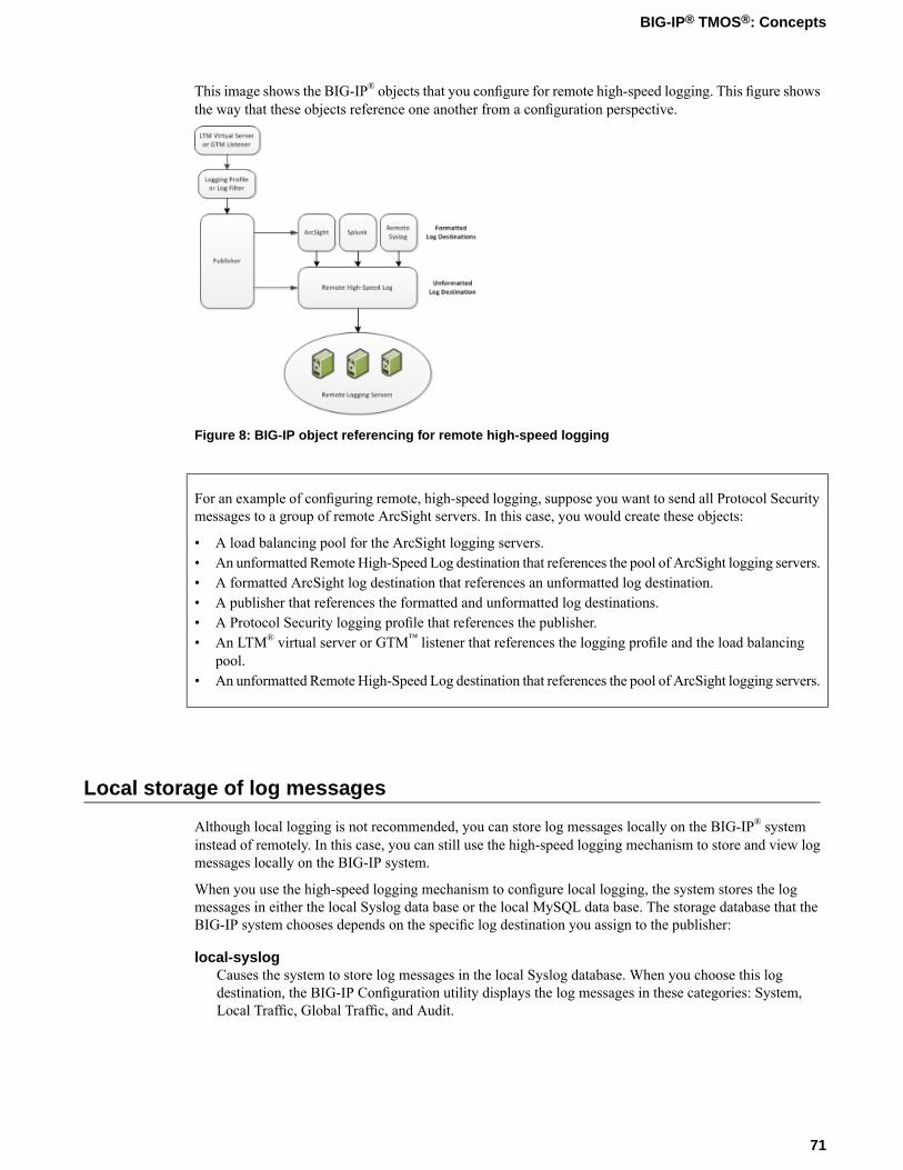
This image shows the BIG-IP® objects that you configure for remote high-speed logging. This figure showsthe way that these objects reference one another from a configuration perspective.
Figure 8: BIG-IP object referencing for remote high-speed logging
For an example of configuring remote, high-speed logging, suppose you want to send all Protocol Securitymessages to a group of remote ArcSight servers. In this case, you would create these objects:
• A load balancing pool for the ArcSight logging servers.• An unformatted Remote High-Speed Log destination that references the pool of ArcSight logging servers.• A formatted ArcSight log destination that references an unformatted log destination.• A publisher that references the formatted and unformatted log destinations.• A Protocol Security logging profile that references the publisher.• An LTM® virtual server or GTM™ listener that references the logging profile and the load balancing
pool.• An unformatted Remote High-Speed Log destination that references the pool of ArcSight logging servers.
Local storage of log messages
Although local logging is not recommended, you can store log messages locally on the BIG-IP® systeminstead of remotely. In this case, you can still use the high-speed logging mechanism to store and view logmessages locally on the BIG-IP system.
When you use the high-speed logging mechanism to configure local logging, the system stores the logmessages in either the local Syslog data base or the local MySQL data base. The storage database that theBIG-IP system chooses depends on the specific log destination you assign to the publisher:
local-syslogCauses the system to store log messages in the local Syslog database. When you choose this logdestination, the BIG-IP Configuration utility displays the log messages in these categories: System,Local Traffic, Global Traffic, and Audit.
71
BIG-IP® TMOS®: Concepts

local-dbCauses the system to store log messages in the local MySQL database. When you choose local-db,the BIG-IP Configuration utility does not display the log messages.
Log level settings for BIG-IP system events
For each type of system-level process, such as bigdb configuration events or events related to HTTPcompression, you can set a minimum log level. The minimum log level indicates the minimum severitylevel at which the BIG-IP® system logs that type of event. There are many different types of local traffic orglobal traffic events for which you can set a minimum log level.
The log levels that you can set on certain types of events, ordered from highest severity to lowest severity,are:
• Emergency• Alert• Critical• Error• Warning• Notice• Informational• Debug
For example, if you set the minimum log level for bigdb events to Error, then the system only logs messagesthat have a severity of Error or higher for those events.
About local Syslog logging
If you are using the Syslog utility for local logging, whether or not you are using the high-speed loggingmechanism you can view and manage the log messages, using the BIG-IP® Configuration utility.
The local Syslog logs that the BIG-IP system can generate include several types of information. For example,some logs show a timestamp, host name, and service for each event. Moreover, logs sometimes include astatus code, while the audit log shows a user name and a transaction ID corresponding to each configurationchange. All logs contain a one-line description of each event.
For local log messages that the BIG-IP system stores in the local Syslog data base, the BIG-IP systemautomatically stores and displays log messages in these categories:
• System messages• Packet filter messages• Local Traffic messages• Global Traffic messages• BIG-IP system configuration (audit) messages
Each type of event is stored locally in a separate log file, and the information stored in each log file variesdepending on the event type. All log files for these event types are in the directory /var/log.
72
Logging

Logging system events
Many events that occur on the BIG-IP® system are Linux-related events, and do not specifically apply tothe BIG-IP system. Using the Configuration utility, you can display these local system messages.
Logging packet filter events
Some of the events that the BIG-IP system logs are related to packet filtering. The system logs the messagesfor these events in the file /var/log/pktfilter.
Logging local traffic events
Many of the events that the BIG-IP system logs are related to local area traffic passing through the BIG-IPsystem. The BIG-IP system logs the messages for these events in the file /var/log/audit.
Logging BIG-IP system configuration changes (audit logging)
Audit logging is an optional feature that logs messages whenever a BIG-IP® system object, such as a virtualserver or a load balancing pool, is configured (that is, created, modified, or deleted). The BIG-IP systemlogs the messages for these auditing events in the file /var/log/audit.
There are three ways that objects can be configured:
• By user action• By system action• By loading configuration data
Whenever an object is configured in one of these ways, the BIG-IP system logs a message to the audit log.
Code expansion in Syslog log messages
The BIG-IP® system log messages contain codes that provide information about the system. You can runthe Linux zcat command at the system prompt to expand the codes in log messages to provide moreinformation. In this example, the bold text is the expansion of the log code 012c0012.
Jun 14 14:28:03 sccp bcm56xxd [ 226 ] : 012c0012 : (Product=BIGIP Subset=BCM565XXD) : 6:4.1 rx [ OK 171009 Bad 0 ] tx [ OK 171014 Bad 0 ]
73
BIG-IP® TMOS®: Concepts
About enabling and disabling auditing logging
An optional type of logging that you can enable is audit logging. Audit logging logs messages that pertainto configuration changes that users or services make to the BIG-IP® system configuration. This type of auditlogging is known asMCP audit logging. Optionally, you can set up audit logging for any tmsh commandsthat users type on the command line.
For both MCP and tmsh audit logging, you can choose a log level. In this case, the log levels do not affectthe severity of the log messages; instead, they affect the initiator of the audit event.
The log levels for MCP logging are:
DisableThis turns audit logging off. This is the default value.
EnableThis causes the system to log messages for user-initiated configuration changes only.
VerboseThis causes the system to log messages for user-initiated configuration changes and any loading ofconfiguration data.
DebugThis causes the system to log messages for all user-initiated and system-initiated configuration changes.
The log levels for tmsh logging are:
DisableThis turns audit logging off. This is the default value.
EnableThis causes the system to log all tmsh commands that the user specifies on the command line. Notethat the system does not generate a log entry when the user invokes tmsh itself.
About remote logging using Syslog-ng
If you want to configure remote logging using Syslog-ng, you do not use the high-speed logging mechanism.Configuration of remote logging using Syslog-ng has some key differences compared to a remote, high-speedlogging configuration:
• You do not configure log destinations, publishers, or a logging profile or log filter.• Instead of creating a pool of remote logging servers (as you do with high-speed logging), you specify
the IP addresses of the servers using the Remote Logging screen of the BIG-IP® Configuration utility.• If you want to ensure that the Syslog-ng messages being logged remotely are encrypted, you must first
establish a secure tunnel.
74
Logging

Chapter
12Interface Concepts
• Introduction to BIG-IP system interfaces• About link layer discovery protocol• Interface properties• About interface mirroring• Neighbor settings• Related configuration tasks

Introduction to BIG-IP system interfaces
A key task of the BIG-IP® system configuration is the configuration of BIG-IP system interfaces. Theinterfaces on a BIG-IP system are the physical ports that you use to connect the BIG-IP system to otherdevices on the network. These other devices can be next-hop routers, Layer 2 devices, destination servers,and so on. Through its interfaces, the BIG-IP system can forward traffic to or from other network devices.
Note: The term interface refers to the physical ports on the BIG-IP system.
Every BIG-IP system includes multiple interfaces. The exact number of interfaces that you have on theBIG-IP system depends on the platform type.
A BIG-IP system has two types of interfaces:
A management interfaceThe management interface is a special interface dedicated to performing a specific set of systemmanagement functions.
TMM switch interfacesTMM switch interfaces are those interfaces that the BIG-IP system uses to send or receive applicationtraffic, that is, traffic slated for application delivery.
Each of the interfaces on the BIG-IP system has unique properties, such as the MAC address, media speed,duplex mode, and support for Link Layer Discovery Protocol (LLDP).
In addition to configuring interface properties, you can implement a feature known as interface mirroring,which you can use to duplicate traffic from one or more interfaces to another. You can also view statisticsabout the traffic on each interface.
Once you have configured the properties of each interface, you can configure several other features of theBIG-IP system that control the way that interfaces operate. For example, by creating a virtual local areanetwork (VLAN) and assigning interfaces to it, the BIG-IP system can insert a VLAN ID, or tag, into framespassing through those interfaces. In this way, a single interface can forward traffic for multiple VLANs.
About link layer discovery protocol
The BIG-IP® system supports Link Layer Discovery Protocol (LLDP). LLDP is a Layer 2 industry-standardprotocol (IEEE 802.1AB) that enables a network device such as the BIG-IP system to advertise its identityand capabilities to multi-vendor neighbor devices on a network. The protocol also enables a network deviceto receive information from neighbor devices.
LLDP transmits device information in the form of LLDPmessages known as LLDPData Units (LLDPDUs).In general, this protocol:
• Advertises connectivity andmanagement information about the local BIG-IP device to neighbor deviceson the same IEEE 802 LAN.
• Receives network management information from neighbor devices on the same IEEE 802 LAN.• Operates with all IEEE 802 access protocols and network media.
Using the BIG-IP Configuration utility or tmsh, you can configure the BIG-IP system interfaces to transmitor receive LLDPDUs. More specifically, you can:
• Specify the exact content of LLDPDUs that a BIG-IP system interface transmits to a neighbor device.You specify this content by configuring the LLDP Attributes setting on each individual interface.
76
Interface Concepts
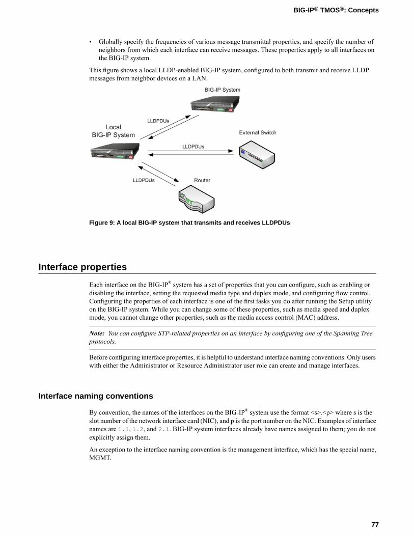
• Globally specify the frequencies of various message transmittal properties, and specify the number ofneighbors from which each interface can receive messages. These properties apply to all interfaces onthe BIG-IP system.
This figure shows a local LLDP-enabled BIG-IP system, configured to both transmit and receive LLDPmessages from neighbor devices on a LAN.
Figure 9: A local BIG-IP system that transmits and receives LLDPDUs
Interface properties
Each interface on the BIG-IP® system has a set of properties that you can configure, such as enabling ordisabling the interface, setting the requested media type and duplex mode, and configuring flow control.Configuring the properties of each interface is one of the first tasks you do after running the Setup utilityon the BIG-IP system. While you can change some of these properties, such as media speed and duplexmode, you cannot change other properties, such as the media access control (MAC) address.
Note: You can configure STP-related properties on an interface by configuring one of the Spanning Treeprotocols.
Before configuring interface properties, it is helpful to understand interface naming conventions. Only userswith either the Administrator or Resource Administrator user role can create and manage interfaces.
Interface naming conventions
By convention, the names of the interfaces on the BIG-IP® system use the format <s>.<p> where s is theslot number of the network interface card (NIC), and p is the port number on the NIC. Examples of interfacenames are 1.1, 1.2, and 2.1. BIG-IP system interfaces already have names assigned to them; you do notexplicitly assign them.
An exception to the interface naming convention is the management interface, which has the special name,MGMT.
77
BIG-IP® TMOS®: Concepts
Viewing interface information and media properties
Using the Configuration utility, you can display a screen that lists all of the BIG-IP® system interfaces, aswell as their current status (UP or DOWN). You can also view other information about each interface:
• MAC address of the interface• Interface availability• Media type• Media speed• Active mode (such as full)
This information is useful when you want to assess the way that a particular interface is forwarding traffic.For example, you can use this information to determine the specific VLANs for which an interface iscurrently forwarding traffic. You can also use this information to determine the speed at which an interfaceis currently operating.
Interface state
You can either enable or disable an interface on the BIG-IP® system. By default, each interface is set toEnabled, where it can accept ingress or egress traffic. When you set the interface to Disabled, the interfacecannot accept ingress or egress traffic.
Fixed Requested Media
The Fixed RequestedMedia property shows that the interface auto-detects the duplex mode of the interface.
About flow control
You can configure the Flow Control property to manage the way that an interface handles pause frames forflow control. Pause frames are frames that an interface sends to a peer interface as a way to control frametransmission from that peer interface. Pausing a peer’s frame transmissions prevents an interface’s First-in,First-out (FIFO) queue from filling up and resulting in a loss of data. Possible values for this property are:
Pause NoneDisables flow control.
Pause TX/RXSpecifies that the interface honors pause frames from its peer, and also generates pause frames whennecessary. This is the default value.
Pause TXSpecifies that the interface ignores pause frames from its peer, and generates pause frames whennecessary.
Pause RXSpecifies that the interface honors pause frames from its peer, but does not generate pause frames.
78
Interface Concepts

About the LLDP property
The LLDP property is one of two properties related to LLDP that you can configure for a specific interface.The possible values for this setting are:
DisabledWhen set to this value, the interface neither transmits (sends) LLDP messages to, nor receives LLDPmessages from, neighboring devices.
Transmit OnlyWhen set to this value, the interface transmits LLDP messages to neighbor devices but does not receiveLLDP messages from neighbor devices.
Receive OnlyWhen set to this value, the interface receives LLDP messages from neighbor devices but does nottransmit LLDP messages to neighbor devices.
Transmit and ReceiveWhen set to this value, the interface transmits LLDP messages to and receives LLDP messages fromneighboring devices.
In addition to the LLDP-related settings that you can configure per interface, you can configure some globalLLDP settings that apply to all interfaces on the system.
Moreover, you can view statistics pertaining to any neighbor devices that have transmitted LLDP messagesto the local BIG-IP® system.
LLDP Attributes
The LLDP Attributes setting is one of two settings related to LLDP that you can configure for a specificinterface. You use this interface setting to specify the content of an LLDP message being sent or received.Each LLDP attribute that you specify with this setting is optional and is in the form of Type, Length, Value(TLV).
About interface mirroring
For reliability reasons, you can configure a feature known as interface mirroring. When you configureinterface mirroring, you cause the BIG-IP® system to copy the traffic on one or more interfaces to anotherinterface that you specify. By default, the interface mirroring feature is disabled.
Neighbor settings
When a BIG-IP® system interface receives LLDP messages from neighbor devices, the BIG-IP systemdisplays chassis, port, and system information about the content of those messages. Specifically, the systemdisplays values for the standard TLVs for each neighbor. These TLVs are:
Chassis IDIdentifies the chassis containing the IEEE 802 LAN station associated with the transmitting LLDP agent.
79
BIG-IP® TMOS®: Concepts
Port IDIdentifies the port component of the media service access point (MSAP) identifier associated with thetransmitting LLDP agent.
Port descriptionAn alpha-numeric string that describes the interface.
System nameAn alpha-numeric string that indicates the administratively-assigned name of the neighbor device.
System descriptionAn alpha-numeric string that is the textual description of the network entity. The system descriptionshould include the full name and version identification of the hardware type, software operating system,and networking software of the neighbor device.
System capabilitiesThe primary functions of the system and whether these primary functions are enabled.
Management addressAn address associated with the local LLDP agent used to reach higher layer entities. This TLV mightalso include the system interface number that is associated with the management address, if known.
Related configuration tasks
After you have configured the interfaces on the BIG-IP® system, one of the primary tasks you perform isto assign those interfaces to the virtual LANs (VLANs) that you create. A VLAN is a logical subset of hostson a local area network (LAN) that reside in the same IP address space.When you assign multiple interfacesto a single VLAN, traffic destined for a host in that VLAN can travel through any one of these interfacesto reach its destination. Conversely, when you assign a single interface to multiple VLANs, the BIG-IPsystem can use that single interface for any traffic that is intended for hosts in those VLANs.
Another powerful feature that you can use for BIG-IP system interfaces is trunking, with link aggregation.A trunk is an object that logically groups physical interfaces together to increase bandwidth. Link aggregation,through the use of the industry-standard Link Aggregation Control Protocol (LACP), provides regularmonitoring of link status, as well as failover if an interface becomes unavailable.
Finally, you can configure the BIG-IP system interfaces to work with one of the spanning tree protocols(STP, RSTP, and MSTP). Spanning tree protocols reduce traffic on your internal network by blockingduplicate routes to prevent bridging loops. The section about Spanning Tree Protocols, describes the spanningtree protocols and the procedure for configuring these protocols on the BIG-IP system. It also includesinformation on setting spanning tree-related properties on individual interfaces.
80
Interface Concepts

Chapter
13Self IP Addresses
• Introduction to self IP addresses• Types of self IP addresses• Self IP addresses and MAC addresses• Self IP addresses for SNATs• Self IP address properties
Introduction to self IP addresses
A self IP address is an IP address on the BIG-IP® system that you associate with a VLAN, to access hostsin that VLAN. By virtue of its netmask, a self IP address represents an address space, that is, a range of IPaddresses spanning the hosts in the VLAN, rather than a single host address. You can associate self IPaddresses not only with VLANs, but also with VLAN groups.
Self IP addresses serve two purposes:
• First, when sending a message to a destination server, the BIG-IP system uses the self IP addresses ofits VLANs to determine the specific VLAN in which a destination server resides. For example, if VLANinternal has a self IP address of 10.10.10.100, with a netmask of 255.255.255.0, and the destinationserver’s IP address is 10.10.10.20 (with a netmask of 255.255.255.255), the BIG-IP systemrecognizes that the server’s IP address falls within the range of VLAN internal’s self IP address, andtherefore sends the message to that VLAN. More specifically, the BIG-IP system sends the message tothe interface that you assigned to that VLAN. If more than one interface is assigned to the VLAN, theBIG-IP system takes additional steps to determine the correct interface, such as checking the Layer2forwarding table.
• Second, a self IP address can serve as the default route for each destination server in the correspondingVLAN. In this case, the self IP address of a VLAN appears as the destination IP address in the packetheader when the server sends a response to the BIG-IP system.
You normally assign self IP addresses to a VLAN when you initially run the Setup utility on a BIG-IPsystem. More specifically, you assign one static self IP address and one floating self IP address to each ofthe default VLANs (internal and external). Later, using the Configuration utility, you can create self IPaddresses for other VLANs that you create.
Self IP addresses reside in administrative partitions/folders and are associated with traffic groups. The selfIP addresses that you create when you run the Setup utility reside in partition Common (that is folder/Common).
Types of self IP addresses
There are two types of self IP addresses that you can create:
• A static self IP address is an IP address that the BIG-IP® system does not share with another BIG-IPsystem. Any self IP address that you assign to the default traffic group traffic-group-local-onlyis a static self IP address.
• A floating self IP address is an IP address that two BIG-IP systems share. Any self IP address that youassign to the default traffic group traffic-group-1 is a floating self IP address.
Self IP addresses and MAC addresses
For each self IP address that you create for a VLAN, the BIG-IP® system automatically assigns a mediaaccess control (MAC) address.
As an alternative, you can globally configure the BIG-IP system to assign the same MAC address to allVLANs. This feature is useful if your network includes a type of switch that does not keep a separate Layer2 forwarding table for each VLAN on that switch.
82
Self IP Addresses
Self IP addresses for SNATs
When you configure the BIG-IP® system to manage local area traffic, you can implement a feature knownas a secure network address translation (SNAT). A SNAT is an object that causes the BIG-IP system totranslate the original source IP address of a packet to an IP address that you specify. A SNAT ensures thatthe target server sends its response back through the BIG-IP system rather than to the original client IPaddress directly.
When you create a SNAT, you can configure the BIG-IP system to automatically choose a translationaddress. This ability of the BIG-IP system to automatically choose a translation address is known as SNATautomapping, and in this case, the translation address that the system chooses is always an existing self IPaddress. Thus, for traffic going from the BIG-IP system to a destination server, configuring SNATautomapping ensures that the source IP address in the header of a packet is a self IP address.
When you create an automapped SNAT, the BIG-IP system actually creates a SNAT pool consisting of thesystem’s internal self IP addresses, and then uses an algorithm to select and assign an address from thatSNAT pool.
Self IP address properties
It is when you initially run the Setup utility on a BIG-IP® system that you normally create any static andfloating self IP addresses and assign them to VLANs. However, if you want to create additional self IPaddresses later, you can do so using the Configuration utility.
Note: Only users with either the Administrator or Resource Administrator user role can create and manageself IP addresses.
Note: A self IP address can be in either IPv4 or IPv6 format.
IP address
A self IP address, combined with a netmask, typically represents a range of host IP addresses in a VLAN.If you are assigning a self IP address to a VLAN group, the self IP address represents the range of self IPaddresses assigned to the VLANs in that group.
Netmask
When you specify a netmask for a self IP address, the self IP address can represent a range of IP addresses,rather than a single host address. For example, a self IP address of 10.0.0.100 can represent several hostIP addresses if you specify a netmask of 255.255.0.0.
VLAN/Tunnel assignment
You assign a unique self IP address to a specific VLAN or a VLAN group:
Assigning a self IP address to a VLANThe self IP address that you assign to a VLAN should represent an address space that includes the selfIP addresses of the hosts that the VLAN contains. For example, if the address of one destination serverin a VLAN is 10.0.0.1 and the address of another server in the VLAN is 10.0.0.2, you could assigna self IP address of 10.0.0.100, with a netmask of 255.255.0.0, to the VLAN.
83
BIG-IP® TMOS®: Concepts
Assigning a self IP address to a VLAN groupThe self IP address that you assign to a VLAN group should represent an address space that includesthe self IP addresses of the VLANs that you assigned to the group. For example, if the self IP addressof one VLAN in a VLAN group is 10.0.20.100 and the address of the other VLAN in a VLAN groupis 10.0.30.100, you could assign an address of 10.0.0.100, with a netmask of 255.255.0.0, tothe VLAN group.
The VLAN/Tunnel list in the BIG-IP Configuration utility displays the names of all existing VLANs andVLAN groups.
Port lockdown
Each self IP address has a feature known as port lockdown. Port lockdown is a security feature that allowsyou to specify particular UDP and TCP protocols and services from which the self IP address can accepttraffic.
You can determine the supported protocols and services by using the tmsh command tmsh list netself-allow defaults.
If you do not want to use the default setting (Allow None), you can configure port lockdown to allow eitherall UDP and TCP protocols and services (Allow All) or only those that you specify (Allow Custom).
Note: High availability-related traffic from configured peer devices in a device group might not be subjectto port lockdown settings.
Traffic groups
If you want the self IP address to be a floating IP address, that is, an address shared between two or moreBIG-IP devices in a device group, you can assign a floating traffic group to the self IP address. A floatingtraffic group causes the self IP address to become a floating self IP address.
A floating self IP address ensures that application traffic reaches its destination. More specifically, a floatingself IP address enables a source node to successfully send a request, and a destination node to successfullysend a response, when the relevant BIG-IP device is unavailable.
If you want the self IP address to be a static (non-floating) IP address (used mostly for standalone devices),you can assign a non-floating traffic group to the self IP address. A non-floating traffic group causes theself IP address to become a non-floating self IP address. An example of a non-floating self IP address is theaddress that you assign to the default VLAN named HA, which is used strictly to process failovercommunications between BIG-IP devices, instead of processing application traffic.
84
Self IP Addresses
Chapter
14Packet Filters
• Introduction to packet filtering• Global settings• Global properties• Global exemptions• Order of packet filter rules• About the action setting in packet filter rules• Rate class assignment• One or more VLANs• Logging• About filter expression creation
Introduction to packet filtering
Packet filters enhance network security by specifying whether a BIG-IP® system interface should accept orreject certain packets based on criteria that you specify. Packet filters enforce an access policy on incomingtraffic. They apply to incoming traffic only.
You implement packet filtering by creating packet filter rules, using the BIG-IP Configuration utility. Theprimary purpose of a packet filter rule is to define the criteria that you want the BIG-IP system to use whenfiltering packets. Examples of criteria that you can specify in a packet filter rule are:
• The source IP address of a packet• The destination IP address of a packet• The destination port of a packet
You specify the criteria for applying packet filter rules within an expression. When creating a packet filterrule, you can instruct the BIG-IP system to build an expression for you, in which case you need only choosethe criteria from predefined lists, or you can write your own expression text, using the syntax of the tcpdumputility. For more information on the tcpdump utility, see the online man page for the tcpdump command.
Note: Packet filter rules are unrelated to iRules®
You can also configure global packet filtering that applies to all packet filter rules that you create.
Global settings
Global settings for packet filtering are divided into two categories: Properties and Exemptions. The BIG-IP®
system applies global settings to all packets coming into the BIG-IP system.
Important: Note that one of the global settings, Packet Filtering, enables packet filtering. When you disablethis setting, no packet filter settings or packet filter rules operate, and the BIG-IP system allows all trafficby default.
Global properties
You can configure three specific global properties for packet filtering.
Packet filter enabling
Before you can implement packet filtering on the BIG-IP® system, you must enable the packet filter feature.You do this by changing the Packet Filtering setting to Enabled. The default setting for packet filteringis Disabled.
Control of unhandled packets
Sometimes a packet does not match any of the criteria that you have specified in the packet filter rules thatyou have created. For this reason, youmust configure theUnhandled Packet Action property, which specifiesthe action that the BIG-IP system should take when the packet does not match packet filter rule criteria.
86
Packet Filters
Possible values for this setting are Accept, Discard, and Reject. The default value is Accept.
Warning: Changing the default value of the Unhandled Packet Action property can produce unwantedconsequences. Before changing this value to Discard or Reject, make sure that any traffic that you wantthe BIG-IP system to accept meets the criteria specified in your packet filter rules.
Other options
Using the Options property, you can configure two other options:
Filter established connectionsWhen you enable (check) this option, the BIG-IP system filters all ingress packets, even if the packetsare part of an existing connection. The default setting is disabled (unchecked). Note that checking thisoption does not typically enhance security, and can impact system performance.
Send ICMP error on packet rejectWhen you enable (check) this option, the system sends an ICMP type 3 (destination unreachable), code13 (administratively prohibited) packet when an ingress packet is rejected. When you disable (clear)this option, the BIG-IP system sends an ICMP reject packet that is protocol-dependent. The defaultsetting for this option is disabled (cleared).
Global exemptions
There are a number of exemptions you can set for packet filtering. When filtering packets, the BIG-IP®
system always applies these exemptions, effectively overriding certain criteria you might have previouslyset within an individual packet filter rule.
VLANs
Using the VLANs setting, you can configure the BIG-IP system so that traffic from one or more specifiedVLANs is exempt from packet filtering. In this case, the system does not attempt to match packets fromthe specified VLAN or VLANs to any packet filter rule. Instead, the BIG-IP system always accepts trafficfrom the specified VLAN or VLANs.
For example, if you specify VLAN internal, then no incoming packets from VLAN internal are subject topacket filtering, even if a packet matches the criteria of a packet filter rule.
Possible values are:
Always AcceptWhen you select this value, a VLAN List setting appears. You can then specify one or more VLANsfrom which traffic should be exempt from packet filtering.
NoneWhen you select this value, traffic from all VLANs is subject to packet filtering, according to existingpacket filter rule criteria. This is the default value.
Protocols
With the Protocols setting, you can specify whether ARP and certain ICMP messages are exempt frompacket filtering. The individual settings are:
87
BIG-IP® TMOS®: Concepts
Always accept ARPWhen you enable (check) this setting, the system automatically accepts all ARP packets and thereforedoes not subject them to packet filtering. The default setting is enabled (checked).
Always accept important ICMPWhen you enable (check) this setting, the system automatically accepts the following ICMP packettypes for IPv4, and therefore does not subject them to packet filtering:
• UNREACH• SOURCEQUENCH• REDIRECT• TIMEXCEED
The default setting is enabled.
MAC addresses
You can use theMACAddresses setting to exempt traffic from certainMAC addresses from packet filtering.Possible values are:
Always AcceptWhen you select this value, a MAC Address List setting appears. You can then specify one or moreMAC addresses from which traffic should be exempt from packet filtering.
NoneWhen you select this value, traffic from all MAC addresses is subject to packet filtering, according toexisting packet filter rule criteria. This is the default value.
IP addresses
You can use the IP Addresses setting to exempt traffic from certain IP addresses from packet filtering.Possible values are:
Always AcceptWhen you select this value, an IP Address List setting appears. You can then specify one or more IPaddresses from which traffic should be exempt from packet filtering.
NoneWhen you select this value, traffic from all IP addresses is subject to packet filtering, according toexisting packet filter rule criteria. This is the default value.
VLANs
Using the VLANs setting, you can configure the BIG-IP® system so that traffic from one or more specifiedVLANs is exempt from packet filtering. In this case, the system does not attempt to match packets fromthe specified VLAN or VLANs to any packet filter rule. Instead, the BIG-IP system always accepts trafficfrom the specified VLAN or VLANs.
For example, if you specify VLAN internal, then no incoming packets from VLAN internal are subject topacket filtering, even if a packet matches the criteria of a packet filter rule.
Possible values are:
88
Packet Filters
Always AcceptWhen you select this value, a VLAN List setting appears. You can then specify one or more VLANsfrom which traffic should be exempt from packet filtering.
NoneWhen you select this value, traffic from all VLANs is subject to packet filtering, according to existingpacket filter rule criteria. This is the default value.
Order of packet filter rules
You use the Order setting to specify the order in which you want the BIG-IP® system to apply existingpacket filter rules. This setting is required. Possible values for this setting are:
FirstSelect this value if you want this packet filter rule to be the first rule that the BIG-IP system applies.
LastSelect this value if you want this packet filter rule to be the last rule that the BIG-IP system applies.
AfterSelect this value, and then select a packet filter rule from the list, if you want the system to apply thispacket filter after the packet filter that you select from the list. Note that this setting is most useful whenyou have more than three packet filter rules configured.
About the action setting in packet filter rules
When a packet matches the criteria that you have specified in a packet filter rule, the BIG-IP® system cantake a specific action. You define this action using the Action setting. You can choose one of these actions:
AcceptSelect Accept if you want the system to accept the packet, and stop processing additional packet filterrules, if any exist. This is the default setting.
DiscardSelect Discard if you want the system to drop the packet, and stop processing additional packet filterrules, if any exist.
RejectSelect Reject if you want the system to drop the packet, and also send a rejection packet to the sender,indicating that the packet was refused. Note that the behavior of the system when you select the Rejectaction depends on how you configured the general packet filter Options property, Send ICMP Error onPacket Reject.
ContinueSelect Continue if you simply want the system to acknowledge the packet for logging or statisticalpurposes. Setting the Action value to Continue does not affect the way that the BIG-IP system handlesthe packet; the system continues to evaluate traffic matching a rule, starting with the next packet filterrule in the list.
89
BIG-IP® TMOS®: Concepts

Rate class assignment
Using the Rate Class setting, you can assign a rate class to traffic that matches the criteria defined in apacket filter rule. Note that this setting applies only when you have the rate shaping feature enabled.
The default value for this setting is None. If you previously created rate classes using the rate shapingfeature, you can choose one of those rate classes from the Rate Class list.
One or more VLANs
You use the Apply to VLAN setting to display a list of VLANs and then select a VLAN or VLAN groupname. Selecting a VLAN from the list means that the packet filter rule filters ingress traffic from that VLANonly. For example, if you select the value *All VLANS, the BIG-IP® system applies the packet filter ruleto all traffic coming into the BIG-IP system.
Similarly, if you select the VLAN internal, the BIG-IP system applies the packet filter rule to traffic fromVLAN internal only. The default value is *All VLANS.
If you select the name of a VLAN group instead of an individual VLAN, the packet filter rule applies to allVLANs in that VLAN group.
Logging
If you want to generate a log message each time a packet matches a rule, you can enable logging for thepacket filter rule. With this configuration, you can then display the Logging screen in the Configurationutility and view events related to packet filtering.
About filter expression creation
To match incoming packets, the BIG-IP® system must use a filter expression. A filter expression specifiesthe criteria that you want the BIG-IP system to use when filtering packets. For example, the BIG-IP systemcan filter packets based on the source or destination IP address in the header of a packet.
Using the Configuration utility, you can create a filter expression in either of two ways:
• You can write your own expression, using a Filter Expression box.• You can specify a set of criteria (such as source or destination IP addresses) that you want the BIG-IP
system to use when filtering packets. When you use this method, the BIG-IP system builds a filterexpression for you.
You can have as many rules as you want, limited only by the available memory. Of course, the morestatements you have, the more challenging it is to understand and maintain your packet filters.
90
Packet Filters

Chapter
15Rate Shaping
• Introduction to rate shaping• About rate classes• Rate class name• Base rate• Ceiling rate• Burst size• Depleting the burst reservoir• Replenishing a burst reservoir• About specifying a non-zero burst size• About the direction setting• About the parent class• About shaping policy• About queue method• About drop policy
Introduction to rate shaping
The BIG-IP® system includes a feature called rate shaping. Rate shaping allows you to enforce a throughputpolicy on incoming traffic. Throughput policies are useful for prioritizing and restricting bandwidth onselected traffic patterns.
Rate shaping can be useful for an e-commerce site that has preferred clients. For example, the site mightwant to offer higher throughput for preferred customers, and lower throughput for other site traffic.
The rate shaping feature works by first queuing selected packets under a rate class, and then dequeuing thepackets at the indicated rate and in the indicated order specified by the rate class. A rate class is a rate-shapingpolicy that defines throughput limitations and a packet schedulingmethod to be applied to all traffic handledby the rate class.
You configure rate shaping by creating one or more rate classes and then assigning the rate class to a packetfilter or to a virtual server. You can also use the iRules® feature to instruct the BIG-IP system to apply arate class to a particular connection.
You can apply a rate class specifically to traffic from a server to a client or from a client to a server. If youconfigure the rate class for traffic that is going to a client, the BIG-IP system does not apply the throughputpolicy to traffic destined for the server. Conversely, if you configure the rate class for traffic that is goingto a server, the BIG-IP system does not apply the throughput policy to traffic destined for the client.
About rate classes
A rate class defines the throughput limitations and packet scheduling method that you want the BIG-IP®
system to apply to all traffic that the rate class handles. You assign rate classes to virtual servers and packetfilter rules, as well as through iRules®.
If the same traffic is subject to rate classes that you have assigned from more than one location, the BIG-IPsystem applies the last-assigned rate class only. The BIG-IP system applies rate classes in the followingorder:
• The first rate class that the BIG-IP system assigns is from the last packet filter rule that matched thetraffic and specified a rate class.
• The next rate class that the BIG-IP system assigns is from the virtual server; if the virtual server specifiesa rate class, the rate class overrides any rate class that the packet filter selects.
• The last rate class assigned is from the iRule; if the iRule specifies a rate class, this rate class overridesany previously-selected rate class.
Note: Rate classes cannot reside in partitions. Therefore, a user’s ability to create and manage rate classesis defined by user role, rather than partition-access assignment.
You can create a rate class using the BIG-IP Configuration utility. After you have created a rate class, youmust assign it to a virtual server or a packet filter rule, or you must specify the rate class from within aniRule.
92
Rate Shaping
Rate class name
The first setting you configure for a rate class is the rate class name. Rate class names are case-sensitiveand may contain letters, numbers, and underscores (_) only. Reserved keywords are not allowed.
Each rate class that you define must have a unique name. This setting is required.
To specify a rate class name, locate the Name field on the New Rate Class screen and type a unique namefor the rate class.
Base rate
The Base Rate setting specifies the base throughput rate allowed for traffic that the rate class handles. Thesum of the base rates of all child rate classes attached to a parent rate class, plus the base rate of the parentrate class, cannot exceed the ceiling of the parent rate class. For this reason, F5 Networks® recommendsthat you always set the base rate of a parent rate class to 0 (the default value).
You can specify the base rate in bits per second (bps), kilobits per second (Kbps), megabits per second(Mbps), or gigabits per second (Gbps). The default unit is bits per second. This setting is required.
Note: These numbers are powers of 10, not powers of 2.
Ceiling rate
The Ceiling Rate setting specifies the absolute limit at which traffic is allowed to flow when bursting orborrowing. You can specify the ceiling in bits per second (bps), kilobits per second (Kbps), megabits persecond (Mbps), or gigabits per second (Gbps). The default unit is bits per second.
If the rate class is a parent rate class, the value of the ceiling defines the maximum rate allowed for the sumof the base rates of all child rate classes attached to the parent rate class, plus the base rate of the parent rateclass.
Note: A child rate class can borrow from the ceiling of its parent rate class.
Burst size
You use the Burst Size setting when you want to allow the rate of traffic flow that a rate class controls toexceed the base rate. Exceeding the base rate is known as bursting. When you configure a rate class to allowbursting (by specifying a value other than 0), the BIG-IP® system saves any unused bandwidth and usesthat bandwidth later to enable the rate of traffic flow to temporarily exceed the base rate. Specifying a burstsize is useful for smoothing out traffic patterns that tend to fluctuate or exceed the base rate, such as HTTPtraffic.
93
BIG-IP® TMOS®: Concepts
The value of theBurst Size setting defines the maximum number of bytes that you want to allow for bursting.Thus, if you set the burst size to 5,000 bytes, and the rate of traffic flow exceeds the base rate by 1,000 bytesper second, then the BIG-IP system allows the traffic to burst for a maximum of five seconds.
When you specify a burst size, the BIG-IP system creates a burst reservoir of that size. A burst reservoirstores bandwidth that the BIG-IP system uses for bursting later. The burst reservoir becomes depleted asthe rate of traffic flow exceeds the base rate, and is replenished as the rate of traffic falls below the baserate. The Burst Size value that you configure in a rate class thus represents:
• The maximum number of bytes that the rate class is allowed to transmit when the traffic-flow rateexceeds the base rate
• The maximum number of bytes that the BIG-IP system can replenish into the burst reservoir• The amount of bandwidth initially available for bursting beyond the base rate
The burst size is measured in bytes. For example, a value of either 10000 or 10K equals 10,000 bytes. Thedefault value is 0.
Depleting the burst reservoir
When the rate of traffic flow exceeds the base rate, the BIG-IP® system automatically depletes the burstreservoir, at a rate determined by the number of bytes per second that the traffic flow exceeds the base rate.
Continuing with our previous example in which traffic flow exceeds the base rate by 1,000 bytes per second,if the traffic-flow rate only exceeds the base rate for two seconds, then 2,000 bytes are depleted from theburst size and the maximum bytes available for bursting decreases to 3,000.
Note: In some cases, a rate class can borrow bandwidth from the burst reservoir of its parent class.
Replenishing a burst reservoir
When the rate of traffic flow falls below the base rate, the BIG-IP® system stores the unused bandwidth(that is, the difference between the base rate and the actual traffic-flow rate) in the burst reservoir. Later,the BIG-IP system uses this bandwidth when traffic flow exceeds the base rate. Thus, the BIG-IP systemreplenishes the burst reservoir whenever it becomes depleted due to traffic flow exceeding the base rate.
The size of the burst reservoir cannot exceed the specified burst size. For this reason, the BIG-IP systemreplenishes the reservoir with unused bandwidth only until the reservoir reaches the amount specified bythe Burst Size setting. Thus, if the burst size is set to 5,000, then the BIG-IP system can store only 5,000bytes of unused bandwidth for later use when the rate of traffic flow exceeds the base rate.
Note: Specifying a burst size does not allow the rate class to exceed its ceiling.
About specifying a non-zero burst size
This example illustrates the behavior of the BIG-IP® system when you set the Burst Size setting to a valueother than 0.
94
Rate Shaping

This example shows throughput rates in units of bytes-per-second instead of the default bits-per-second.This is only to simplify the example. You can derive bytes-per-second from bits-per-second by dividingthe bits-per-second amount by 8.
Suppose you configure the rate class settings with these values:
• Base rate: 1,000 bytes per second• Ceiling rate: 4,000 bytes per second• Burst size: 5,000 bytes
Consider the following scenario:
If traffic is currently flowing at 800 bytes per secondNo bursting is necessary because the rate of traffic flow is below the base rate defined in the rate class.Because the traffic is flowing at 200 bytes per second less than the base rate, the BIG-IP system canpotentially add 200 bytes of unused bandwidth to the burst reservoir. However, because no bursting hasoccurred yet, the reservoir is already full at the specified 5,000 bytes, thus preventing the BIG-IP systemfrom storing the 200 bytes of unused bandwidth in the reservoir. In this case, the BIG-IP system simplydiscards the unused bandwidth.
If traffic climbs to 1,000 bytes per second (equal to the base rate)Still no bursting occurs, and there is no unused bandwidth.
If traffic jumps to 2,500 bytes per secondFor each second that the traffic continues to flow at 2,500 bytes per second, the BIG-IP system empties1,500 bytes from the burst reservoir (the difference between the traffic flow rate and the base rate). Thisallows just over three seconds of bursting at this rate before the burst reservoir of 5,000 bytes is depleted.Once the reservoir is depleted, the BIG-IP system reduces the traffic flow rate to the base rate of 1,000bytes per second, with no bursting allowed.
If traffic drops back down to 800 bytes per secondNo bursting is necessary, but now the BIG-IP system can add the 200 bytes per second of unusedbandwidth back into the burst reservoir because the reservoir is empty. If traffic continues to flow at800 bytes per second, the burst reservoir becomes fully replenished from 0 to 5,000 bytes in 25 seconds(at a rate of 200 bytes per second). If traffic stops flowing altogether, creating 1,000 bytes per secondof unused bandwidth, then the BIG-IP system adds 1,000 bytes per second into the burst reservoir, thusreplenishing the reservoir from 0 to 5,000 bytes in only 5 seconds.
About the direction setting
Using the Direction setting, you can apply a rate class to client or server traffic. Thus, you can apply a rateclass to traffic going to a client, to a server, or to both client and server. Possible values are Any, Client,and Server. The default value is Any.
Specifying direction is useful in cases where the nature of the traffic is directionally-biased. For example,if you offer an FTP service to external clients, you might be more interested in limiting throughput for thoseclients uploading files to your site than you are for clients downloading files from your site. In this case,you would select Server as the direction for your FTP rate class, because the Server value only applies yourthroughput restriction to traffic going from the client to the server.
95
BIG-IP® TMOS®: Concepts

About the parent class
When you create a rate class, you can use the Parent Class setting to specify that the rate class has a parentclass. This allows the child rate class to borrow unused bandwidth from the ceiling of the parent class. Achild class can borrow unused bandwidth from the ceiling of its parent, but a parent class cannot borrowfrom a child class. Borrowing is also not possible between two child classes of the same parent class orbetween two unrelated rate classes.
A parent class can itself have a parent, provided that you do not create a circular dependency. A circulardependency is a relationship where a rate class is a child of itself, directly or indirectly.
If a rate class has a parent class, the child class can take unused bandwidth from the ceiling of the parentclass. The process occurs in this way:
• If the rate of traffic flow to which the child class is applied exceeds its base rate, the child class beginsto deplete its burst reservoir as described previously.
• If the reservoir is empty (or no burst size is defined for the rate class), then the BIG-IP® system takesunused base-rate bandwidth from the ceiling of the parent class and gives it to the child class.
• If the unused bandwidth from the parent class is depleted, then the child class begins to use the reservoirof the parent class.
• If the reservoir of the parent class is empty (or no burst size is defined for the parent class), then thechild class attempts to borrow bandwidth from the parent of the parent class, if the parent class has aparent class.
• This process continues until there is no remaining bandwidth to borrow or there is no parent from whichto borrow.
Borrowing only allows the child to extend its burst duration; the child class cannot exceed the ceiling underany circumstance.
Note: Although the above description uses the term “borrowing”, bandwidth that a child class borrows isnot paid back to the parent class later, nor is unused bandwidth of a child class returned to its parent class.
About shaping policy
This setting specifies a shaping policy that includes customized values for drop policy and queue method.The default value is None.
You can create additional shaping policies using the Traffic Management shell (tmsh).
About queue method
TheQueueMethod setting determines the method and order in which the BIG-IP® system dequeues packets.
A rate class supports two queue methods:
Stochastic Fair QueueStochastic Fair Queueing (SFQ) is a queuing method that queues traffic under a set of many lists,choosing the specific list based on a periodically-changing hash of the connection information. Thisresults in traffic from the same connection always being queued in the same list. SFQ then dequeues
96
Rate Shaping

traffic from the set of the lists in a round-robin fashion. The overall effect is that fairness of dequeuingis achieved because one high-speed connection cannot monopolize the queue at the expense of slowerconnections.
Priority FIFOThe Priority FIFO (PFIFO) queuing method queues all traffic under a set of five lists based on the Typeof Service (ToS) field of the traffic. Four of the lists correspond to the four possible ToS values (Minimumdelay, Maximum throughput, Maximum reliability, and Minimum cost). The fifth list represents trafficwith no ToS value. The PFIFO method then processes these five lists in a way that attempts to preservethe meaning of the ToS field as much as possible. For example, a packet with the ToS field set toMinimum cost might yield dequeuing to a packet with the ToS field set to Minimum delay.
About drop policy
The BIG-IP® system drops packets whenever the specified rate limit is exceeded. A drop policy specifiesthe way that you want the system to drop packets. The default value is fred.
Note: You cannot use fred or red, if you select sfq for the Queue Method setting.
Possible values are:
fredSpecifies that the system uses Flow-based RandomEarly Detection to determine whether to drop packets,based on the aggressiveness of each flow. If you require flow fairness across the rate class, select fred.
redSpecifies that the system randomly drops packets.
tailSpecifies that the system drops the end of the traffic stream.
You can create additional drop policies using the Traffic Management shell (tmsh).
97
BIG-IP® TMOS®: Concepts


Chapter
16Spanning Tree Protocol
• Introduction to spanning tree protocols• About STP protocol• About the RSTP protocol• About the MSTP protocol• About spanning tree with legacy bridges• Configuration overview• Spanning tree mode• Global timers• About the transmit hold count option• MSTP-specific global properties• Management of spanning tree instances• Interfaces for spanning tree

Introduction to spanning tree protocols
On networks that contain redundant paths between Layer 2 devices, a common problem is bridging loops.Bridging loops occur because Layer 2 devices do not create boundaries for broadcasts or packet floods.Consequently, Layer 2 devices can use redundant paths to forward the same frames to each other continuously,eventually causing the network to fail.
To solve this problem, the BIG-IP® system supports a set of industry-standard, Layer 2 protocols known asspanning tree protocols. Spanning tree protocols block redundant paths on a network, thus preventingbridging loops. If a blocked, redundant path is needed later because another path has failed, the spanningtree protocols clear the path again for traffic. The spanning tree protocols that the BIG-IP system supportsare Spanning Tree Protocol (STP), Rapid Spanning Tree Protocol (RSTP), and Multiple Spanning TreeProtocol (MSTP).
Central to the way that spanning tree protocols operate is the use of bridge protocol data units (BPDUs).When you enable spanning tree protocols on Layer 2 devices on a network, the devices send BPDUs toeach other, for the purpose of learning the redundant paths and updating their L2 forwarding tablesaccordingly, electing a root bridge, building a spanning tree, and notifying each other about changes ininterface status.
Note: The term bridge refers to a Layer 2 device such as a switch, bridge, or hub.
About STP protocol
STP is the original spanning tree protocol, designed to block redundant paths as a way to prevent bridgingloops. The STP algorithm creates one, and only one, spanning tree for the entire network. A spanning treeis a logical tree-like depiction of the bridges on a network and the paths that connect them.
Because STP is unable to recognize VLANs and usually exhibits poor performance overall, STP is not thepreferred spanning tree protocol to use in VLAN-rich environments. However, all participating interfacesin the spanning tree must use the same spanning tree protocol at any given time. Thus, when you have legacybridges in your environment that are running STP, interfaces on the BIG-IP® system must have the abilityto automatically degrade to STP.
Because STP has no knowledge of VLANs, you can have only one spanning tree instance on the BIG-IPsystem when using STP.
About the RSTP protocol
RSTP is an enhancement to STP, and was designed specifically to improve spanning tree performance. LikeSTP, RSTP can create only one spanning tree (instance 0), and therefore cannot take VLANs into accountwhenmanaging redundant paths. However, RSTP’s performance improvements generally make it preferableto STP in non-VLAN environments.
In the case where legacy RSTP bridges are on the network, BIG-IP® system interfaces running MSTP candegrade to RSTP, just as they can degrade to STP.
Like STP, RSTP allows only one spanning tree instance on the BIG-IP system.
100
Spanning Tree Protocol
About the MSTP protocol
MSTP is an enhancement to RSTP and is the preferred spanning tree protocol for the BIG-IP® system.MSTP is specifically designed to understand VLANs and VLAN tagging (specified in IEEE 802.1q). UnlikeSTP and RSTP, which allow only one spanning tree instance per system, MSTP allows multiple spanningtree instances. Each instance corresponds to a spanning tree, and can control one or more VLANs that youspecify when you create the instance. Thus, for any BIG-IP system interface that you assigned to multipleVLANs, MSTP can block a path on one VLAN, while still keeping a path in another VLAN open for traffic.Neither STP nor RSTP has this capability.
A unique feature of MSTP is the concept of spanning tree regions. A spanning tree region is a logical setof bridges on the network that share the same values for certain MSTP configuration settings. Theseconfiguration settings are: The MSTP configuration name, the MSTP configuration number, the instancenumbers, and the VLAN members of each instance. When the values of these settings are identical on twoor more bridges, the spanning tree algorithm considers these bridges to constitute an MSTP region. AnMSTP region indicates to the spanning tree algorithm that it can use MSTP for all bridges in that region,and thus take VLANs into account when blocking and unblocking redundant paths.
You do not explicitly create a region. The spanning tree algorithm automatically groups bridges into regions,based on the values you assign to the MSTP configuration name, revision number, instance numbers, andinstance members.
MSTP can only operate on bridges that are within a region. However, if the BIG-IP system connects to abridge in a different MSTP region or outside of an MSTP region, the system still participates in spanningtree. In this case, the system is part of the spanning tree instance 0, also known as the Common and InternalSpanning Tree (CIST).
Note: BIG-IP systems released prior to version 9.0 do not support MSTP.
About spanning tree with legacy bridges
A key concept about spanning tree protocols on the BIG-IP® system is the concept of protocol degradation.Protocol degradation occurs when the spanning tree mode on the BIG-IP system is set to MSTP or RSTP,but the system detects legacy bridges (that is, bridges running an older protocol type) on the network. Inthis case, the BIG-IP system automatically degrades the spanning tree protocol that is running on eachapplicable interface to match the protocol running on the legacy device.
For example, suppose you set the BIG-IP system to run in MSTP mode. Later, if a bridge running STP isadded to the network, the BIG-IP systemwill detect the legacy device and automatically degrade the protocolrunning on the BIG-IP system interfaces fromMSTP to STP. The mode is still set toMSTP, but the interfacesactually run STP.
If the legacy device is later removed from the network, you can choose, for each BIG-IP system interface,to manually reset the spanning tree protocol back to MSTP.
The basic principle of protocol degradation is that each BIG-IP system interface in a spanning tree runs theoldest protocol that the system detects on the Layer 2 devices of the network. Thus, if a legacy bridgerunning STP is added to the network, BIG-IP system interfaces running MSTP or RSTP degrade to STP.Similarly, if a legacy bridge is running RSTP (and no bridges are running STP), interfaces running MSTPdegrade to RSTP.
Note that when a bridge running MSTP must degrade to RSTP, the spanning tree algorithm automaticallyputs the degraded bridge into a separate MSTP region.
101
BIG-IP® TMOS®: Concepts
Configuration overview
Regardless of which spanning tree protocol you choose to use, the BIG-IP® Configuration utility offers acomplete set of default configuration settings. Except for choosing a preferred spanning tree protocol touse, there are very few configuration settings that you need to modify to use the spanning tree featureeffectively.
Note: An alternate way to configure spanning tree protocols is to use tmsh.
When you configure spanning tree on a BIG-IP system, you must first decide which protocol, or mode, youwant to enable. Because MSTP recognizes VLANs, using MSTP is preferable for the BIG-IP system.However, all bridges in a network environment that want to use spanning tree must run the same spanningtree protocol. If a legacy bridge running RSTP or STP is added to the network, the BIG-IP system mustswitch to that same protocol.
Fortunately, you do not need to continually reconfigure the BIG-IP system spanning tree mode whenevera legacy bridge is added to the network. Instead, a BIG-IP system interface can detect the addition of alegacy bridge and automatically fall back to either RSTP or STP mode. If the legacy bridge is later removedfrom the network, you can use the Configuration utility to manually reset the interface back to runningMSTP.
Once you have enabled a spanning tree mode, you can configure a set of global options. These options arethe same options that are defined in the IEEE standards for the spanning tree protocols. While you can usethe default settings in most cases, a few settings require user input.
Spanning tree mode
TheMode option specifies the particular spanning tree protocol that you want to use on the BIG-IP® system.The default value is Pass Through. The possible values are:
DisabledSpecifies that when the BIG-IP system receives spanning tree frames (BPDUs), it discards the frames.
Pass ThroughSpecifies that when the BIG-IP system receives spanning tree frames (BPDUs), it forwards them to allother interfaces. This is the default setting. When you use Pass Through mode, the BIG-IP system istransparent to spanning tree BPDUs. When set to Pass Through mode, the BIG-IP system is not part ofany spanning tree. Note that Pass Through mode is not part of the IEEE spanning tree protocolspecifications.
STPSpecifies that the BIG-IP system handles spanning tree frames (BPDUs) in accordance with the STPprotocol. This mode allows for legacy systems on the network.
RSTPSpecifies that the BIG-IP system handles spanning tree frames (BPDUs) in accordance with the RSTPprotocol.
MSTPSpecifies that the BIG-IP system handles spanning tree frames (BPDUs) in accordance with the MSTPprotocol.
102
Spanning Tree Protocol
When you set the mode to MSTP or RSTP, and a legacy bridge running STP is subsequently added to thespanning tree, the applicable BIG-IP system interface automatically changes to running STP. However, youcan manually reset an interface to resume operation in RSTP or MSTP mode if the legacy bridge is laterremoved from the spanning tree.
Global timers
All three spanning tree protocols, have the same three global timer values that you can specify: Hello Time,Maximum Age, and Forward Delay.
About the hello time option
When you change the value of the Hello Time option, you change the time interval, in seconds, that theBIG-IP® system transmits spanning tree information (through BPDUs) to adjacent bridges in the network.The default value for this option is 2.
Warning: Although valid values are in the range of 1 to 10 seconds, F5 Networks® highly recommendsthat you use the default value (2 seconds). This value is optimal for almost all configurations.
Note that when running RSTP, you must maintain the following relationship between the Maximum Ageand Hello Time options:
Maximum Age >= 2 * (Hello Time + 1)
About the maximum age option
When you change the value of the Maximum Age option, you change the amount of time, in seconds, thatspanning tree information received from other bridges is considered valid. The default value is 20, and thevalid range is 6 to 40.
Note that when running RSTP, you must maintain the following relationships between the Maximum Ageand the Hello Time and Forward Delay options:
Maximum Age >= 2 * (Hello Time + 1)
Maximum Age <= 2 * (Forward Delay - 1)
About the forward delay option
Primarily used for STP, the Forward Delay option specifies the amount of time, in seconds, that the systemblocks an interface from forwarding network traffic when the spanning tree algorithm reconfigures a spanningtree. The default value is 15, and the valid range is 4 to 30.
This option has no effect on the BIG-IP® system when running in RSTP or MSTP mode, as long as allbridges in the spanning tree use the RSTP orMSTP protocol. However, if the addition of legacy STP bridgescauses neighboring bridges to fall back to running the STP protocol, then the spanning tree algorithm usesthe Forward Delay option when reconfiguring the spanning tree.
Note that when running RSTP, you must maintain the following relationship between the Forward Delayand Maximum Age options:
103
BIG-IP® TMOS®: Concepts
Maximum Age <= 2 * (Forward Delay - 1)
About the transmit hold count option
When you change the value of the Transmit Hold Count option, you change the maximum number ofspanning tree frames (BPDUs) that the system can transmit on a port within the Hello Time interval. Thissetting ensures that the spanning tree frames do not overload the network, even in unstable network conditions.The default value is 6, and the valid range is 1 to 10.
MSTP-specific global properties
If you are running MSTP, you can configure three additional global properties:
MSTP configuration nameApplicable to MSTP only, the MSTP Configuration Name setting represents a global name that youassign to all bridges in a spanning tree region. A spanning tree region is a group of bridges with identicalMSTP configuration names and MSTP configuration revision levels, as well as identical assignment ofVLANs to spanning tree instances. All bridges in the same region must have this same configurationname. The name must contain from 1 to 32 characters. This option only appears on the screen whenyou set the Mode property to MSTP.
MSTP configuration revisionApplicable toMSTP only, theMSTP Configuration Revision setting represents a global revision numberthat you assign to all bridges in a spanning tree region. All bridges in the same region must have thissame configuration revision number. The default value is 0. You can type any value between 0 and65535. This option only appears on the screen when you set the Mode property to MSTP.
Maximum hop numberApplicable to MSTP only, this global property specifies the maximum number of hops that a spanningtree frame (BPDU) can traverse before it is discarded. The default value is 20. You can specify a valuebetween 1 and 255. This option only appears on the screen when you set the Mode property to MSTP.
Management of spanning tree instances
By default, the spanning tree protocol STP is enabled on all of the interfaces of the BIG-IP® system. Thedefault spanning tree configuration includes a single spanning tree instance, named 0. A spanning treeinstance is a discrete spanning tree for a network. While STP and RSTP allow only one spanning treeinstance (instance 0), MSTP allows you to create multiple spanning tree instances, to manage redundantpaths for specific VLANs on the network.
When running MSTP, instances that you create have instance members. An instance member is a VLANthat you assign to an instance when you create that instance. You can assign as many or as few membersto an instance as you deem necessary. By default, all VLANs on the BIG-IP system are members of instance0.
If you create an instance and attempt to add a VLAN that is already a member of another instance, theBIG-IP system deletes the VLAN from the existing instance and adds the VLAN to the new instance.
104
Spanning Tree Protocol
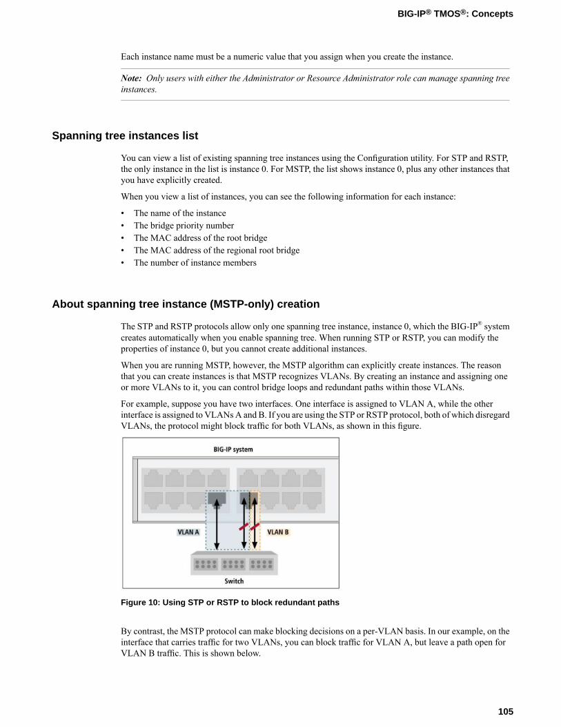
Each instance name must be a numeric value that you assign when you create the instance.
Note: Only users with either the Administrator or Resource Administrator role can manage spanning treeinstances.
Spanning tree instances list
You can view a list of existing spanning tree instances using the Configuration utility. For STP and RSTP,the only instance in the list is instance 0. For MSTP, the list shows instance 0, plus any other instances thatyou have explicitly created.
When you view a list of instances, you can see the following information for each instance:
• The name of the instance• The bridge priority number• The MAC address of the root bridge• The MAC address of the regional root bridge• The number of instance members
About spanning tree instance (MSTP-only) creation
The STP and RSTP protocols allow only one spanning tree instance, instance 0, which the BIG-IP® systemcreates automatically when you enable spanning tree. When running STP or RSTP, you can modify theproperties of instance 0, but you cannot create additional instances.
When you are running MSTP, however, the MSTP algorithm can explicitly create instances. The reasonthat you can create instances is that MSTP recognizes VLANs. By creating an instance and assigning oneor more VLANs to it, you can control bridge loops and redundant paths within those VLANs.
For example, suppose you have two interfaces. One interface is assigned to VLAN A, while the otherinterface is assigned to VLANsA and B. If you are using the STP or RSTP protocol, both of which disregardVLANs, the protocol might block traffic for both VLANs, as shown in this figure.
Figure 10: Using STP or RSTP to block redundant paths
By contrast, the MSTP protocol can make blocking decisions on a per-VLAN basis. In our example, on theinterface that carries traffic for two VLANs, you can block traffic for VLAN A, but leave a path open forVLAN B traffic. This is shown below.
105
BIG-IP® TMOS®: Concepts
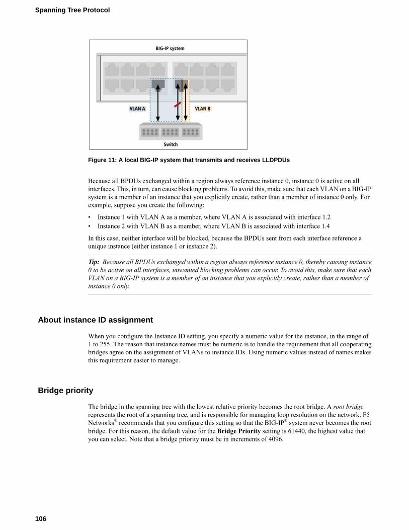
Figure 11: A local BIG-IP system that transmits and receives LLDPDUs
Because all BPDUs exchanged within a region always reference instance 0, instance 0 is active on allinterfaces. This, in turn, can cause blocking problems. To avoid this, make sure that each VLAN on a BIG-IPsystem is a member of an instance that you explicitly create, rather than a member of instance 0 only. Forexample, suppose you create the following:
• Instance 1 with VLAN A as a member, where VLAN A is associated with interface 1.2• Instance 2 with VLAN B as a member, where VLAN B is associated with interface 1.4
In this case, neither interface will be blocked, because the BPDUs sent from each interface reference aunique instance (either instance 1 or instance 2).
Tip: Because all BPDUs exchanged within a region always reference instance 0, thereby causing instance0 to be active on all interfaces, unwanted blocking problems can occur. To avoid this, make sure that eachVLAN on a BIG-IP system is a member of an instance that you explicitly create, rather than a member ofinstance 0 only.
About instance ID assignment
When you configure the Instance ID setting, you specify a numeric value for the instance, in the range of1 to 255. The reason that instance names must be numeric is to handle the requirement that all cooperatingbridges agree on the assignment of VLANs to instance IDs. Using numeric values instead of names makesthis requirement easier to manage.
Bridge priority
The bridge in the spanning tree with the lowest relative priority becomes the root bridge. A root bridgerepresents the root of a spanning tree, and is responsible for managing loop resolution on the network. F5Networks® recommends that you configure this setting so that the BIG-IP® system never becomes the rootbridge. For this reason, the default value for the Bridge Priority setting is 61440, the highest value thatyou can select. Note that a bridge priority must be in increments of 4096.
106
Spanning Tree Protocol

VLAN assignment
If you are runningMSTP, you can addmembers to a spanning tree instance. An instance member is a VLAN.You add members to an instance by associating one or more VLANs with the instance. The interfaces ortrunks associated with each VLAN automatically become part of the spanning tree corresponding to thatinstance.
For two or more bridges to operate in the same spanning tree, all of those bridges must be in the same region,and therefore must have the same instance numbers, instance members, and VLAN tags.
For example, if a bridge has instance 1, with two VLAN members whose tags are 1000 and 2000, then anyother bridges that you want to operate in that spanning tree must also have instance 1 with two VLANmembers whose tags are 1000 and 2000.
A particular VLAN cannot be associated with more than one spanning tree instance. For example, if youhave two instances named 0 and 1, you can only associate VLAN external with one of those instances, notboth. Therefore, before creating an instance, verify that each VLAN you intend to associate with the instanceis not a member of another instance.
Tip: If no VLANs appear in the Available list when creating an instance, it is likely that all VLANs on theBIG-IP® system are members of other instances. You can verify this by viewing the members of otherinstances.
About viewing and modifying a spanning tree instance
Using the Configuration utility, you can view and modify properties of any instance, including instance 0.If you are running MSTP, you can modify the Bridge Priority and VLANs properties. If you are runningRSTP or STP, you can modify only the Bridge Priority property. In no case can you modify the instanceID.
About deleting a spanning tree instance or its members (MSTP-only)
If you are running MSTP, you might have explicitly created some spanning tree instances. If so, you candelete any spanning tree instance except instance 0.
You can also remove VLAN members from an instance. When you remove a VLAN from an instance, theVLAN automatically becomes a member of instance 0. (By default, instance 0 includes any VLAN that isnot a member of another instance.)
If you remove all members from an instance, the BIG-IP® system automatically deletes the instance.
Note: If you are running RSTP or STP, you cannot delete instance 0 or remove members from it.
Interfaces for spanning tree
Some of the configuration tasks you perform when managing a spanning tree protocol pertain to BIG-IP®
system interfaces. The interface-related tasks you perform are:
• Configuring settings on each interface that is to be part of the spanning tree
107
BIG-IP® TMOS®: Concepts

• Managing interfaces per spanning tree instance
Enabling and disabling spanning tree
When you select the check box for the STP setting, you are specifying that the interface can become partof a spanning tree. Once the interface becomes part of the spanning tree, the spanning tree protocol (STP)takes control of all learning and frame forwarding on that interface.
If you disable this setting, the spanning tree protocol treats the interface as non-existent, and does not sendBPDUs to that interface. Also, the interface, and not the spanning tree protocol, controls all learning andframe forwarding for that interface.
Note that you can also enable or disable spanning tree for a trunk. If spanning tree is enabled on the referencelink of a trunk (that is, the lowest-numbered interface of the trunk), then spanning tree is automaticallyenabled on that trunk. To disable spanning tree for a trunk, simply disable spanning tree on the referencelink.
STP link type
When you specify an STP link type, you ensure that STP uses the correct optimizations for the interface.Possible values are:
autoWhen you set the STP link type to auto, the BIG-IP® system determines the spanning tree link type,which is based on the Active Duplex interface property.
p2pWhen you set the STP link type to p2p, the BIG-IP system uses the optimizations for point-to-pointspanning tree links. Point-to-point links connect two spanning tree bridges only. For example, apoint-to-point link might connect a 10 Gigabit link to another bridge. For point-to-point links, the ActiveDuplex property interface should be set to full. Note that p2p is the only valid STP link type for a trunk.
sharedWhen you set the STP link type to shared, the BIG-IP system uses the optimizations for shared spanningtree links. Shared links connect two or more spanning tree bridges. For example, a shared link mightbe a 10 Megabit hub. Note that for shared links, the Active Duplex interface property should be set tohalf.
STP edge port
When you enable the STP Edge Port setting, you are explicitly designating the interface as an edge port.An edge port is an interface that connects to an end station rather than to another spanning tree bridge. Thedefault setting is disabled (not checked).
If you would rather have the system automatically designate the interface as an edge port, you can enablethe STP Edge Port Detection setting instead.
If you enable (check) the STP Edge Port setting and the interface subsequently receives STP, RSTP, orMSTP frames (BPDUs), the system disables the setting automatically, because only non-edge interfacesreceive BPDUs.
108
Spanning Tree Protocol

Detection of an STP edge port
When you enable the STP Edge Port Detection setting, the system determines whether the interface is anedge port, and if so, automatically designates the interface as an edge port. The system determines edgeport status by monitoring the interface and verifying that it does not receive any incoming STP, RSTP, orMSTP frames (BPDUs).
If the system determines that the interface is not an edge port, but you enabled the STP Edge Port settingto explicitly designate the interface as an edge port, the system removes the edge port designation from theinterface. No interface that receives BPDUs from a bridge can have edge port status, despite the values ofthe STP Edge Port and STP Edge Port Detection settings.
About spanning tree protocol reset
The spanning tree algorithm automatically detects the presence of legacy STP bridges on the network, andfalls back to STP mode when communicating with those bridges. Because legacy STP bridges do not sendspanning tree BPDUs periodically in all circumstances, the BIG-IP® system cannot detect when a legacySTP bridge has been removed from the network. Therefore, it is necessary to manually notify the BIG-IPsystem that the algorithm can switch to the RSTP or MSTP protocol again, whenever a legacy bridge hasbeen removed.
About managing interfaces for a specific instance
When you manage an interface for a specific spanning tree instance, you can:
• View a list of interfaces for an instance• View instance-specific properties of an interface• Configure instance-specific settings for an interface
About viewing a list of interface IDs for an instance
Using the Configuration utility, you can view a list of the interface IDs associated with a specific spanningtree instance.
If you are using MSTP, the interface IDs that appear in the list are the interfaces assigned to the VLANsthat you specified when you created the instance. If you are using STP or RSTP, the interface IDs in thelist are those that the BIG-IP® system automatically assigned to instance 0.
The list of interface IDs also displays the following information for each interface:
• The STP instance ID• The priority• The external path cost• The port role
About port roles
The Port Role property of a per-instance interface specifies the interface’s role in the spanning tree instance.You cannot specify a value for this property; the BIG-IP® system automatically assigns a role to the interface.
The BIG-IP system can assign one of the following roles to an instance interface:
109
BIG-IP® TMOS®: Concepts
DisabledThe interface has no active role in the spanning tree instance.
RootThe interface provides a path to a root bridge.
AlternateThe interface provides an alternate path to a root bridge, if the root interface is unavailable.
DesignatedThe interface provides a path away from the root bridge.
BackupThe interface provides an alternate path away from the root bridge, if an interface with a port role ofDesignated is unavailable. The Backup role assignment is rare.
Port states
The Port State property of an interface specifies the way that the interface processes normal data packets.You cannot specify a value for this property; the BIG-IP® system automatically assigns a state to the interface.
An interface can be in one of the following states at any given time:
BlockingThe interface disregards any incoming frames, and does not send any outgoing frames.
ForwardingThe interface passes frames as needed.
LearningThe interface is determining information about MAC addresses, and is not yet forwarding frames.
Settings to configure for an interface for a specific instance
Selecting an interface priority
Each interface has an associated priority within a spanning tree instance. The relative values of the interfacepriorities affect which interfaces the system chooses to carry network traffic. Using the Interface Prioritysetting, you can select the interface's priority in relation to the other interfaces that are members of thespanning tree instance.
Typically, the system is more likely to select interfaces with lower numeric values to carry network traffic.A priority value that you assign to an interface can be in the range of 0 to 240, in increments of 16. Thus,the value you assign to an interface can be 0, 16, 32, 64, and so on, up to 240.
The default priority for an interface is 128, the middle of the valid range.
Specifying path cost
Each interface has an associated path cost within a spanning tree instance. The path cost represents therelative cost of sending network traffic through that interface. When calculating the spanning tree, thespanning tree algorithm attempts to minimize the total path cost between each point of the tree and the rootbridge. By manipulating the path costs of different interfaces, you can steer traffic toward paths that areeither faster, more reliable, more economical, or have all of these qualities.
110
Spanning Tree Protocol

The value of a path cost can be in the range of 1 to 200,000,000, unless you have legacy STP bridges. Inthat case, because some legacy implementations support a range of only 1 to 65535, you should use thismore restricted range when setting path costs on interfaces.
The default path cost for an interface is based on the maximum speed of the interface rather than the actualspeed.
For example, an interface that has a maximum speed of 1000 Mb/s (1 Gb/s), but is currently running at aspeed of 10 Mb/s, has a default path cost of 20,000.
Link aggregation does not affect the default path cost. For example, if a trunk has four 1 Gb/s interfaces,the default path cost is 20,000.
For MSTP, you can set two kinds of path costs, external and internal. For STP and RSTP, you can set anexternal path cost only.
External Path CostThe External Path Cost setting is used to calculate the cost of sending spanning tree traffic throughthe interface to reach an adjacent spanning tree region. The spanning tree algorithm tries to minimizethe total path cost between each point of the tree and the root bridge. The external path cost applies onlyto those interfaces (and trunks) that are members of instance 0.
Internal Path CostThe Internal Path Cost setting allows you to specify the relative cost of sending spanning tree trafficthrough the interface to adjacent bridges within a spanning tree region. Note that the internal path costapplies only to bridges that support the MSTP mode. The internal path cost applies to those interfaces(and trunks) that are members of any instance, including instance 0.
To summarize, STP and RSTP use external path costs only, and the costs apply to instance 0 interfacesonly. MSTP uses both external and internal path costs, and the internal costs apply to interfaces in allspanning tree instances, including instance 0.
111
BIG-IP® TMOS®: Concepts


Chapter
17Trunks
• Introduction to trunks• How do trunks work?• Overview of LACP• Trunk name• Interfaces for a trunk• About enabling LACP• LACP mode• LACP timeout• Link selection policy• Automatic link selection• Maximum bandwidth link selection• Frame distribution hash

Introduction to trunks
A trunk is a logical grouping of interfaces on the BIG-IP® system. When you create a trunk, this logicalgroup of interfaces functions as a single interface. The BIG-IP system uses a trunk to distribute traffic acrossmultiple links, in a process known as link aggregation. With link aggregation, a trunk increases the bandwidthof a link by adding the bandwidth of multiple links together. For example, four fast Ethernet (100 Mbps)links, if aggregated, create a single 400 Mbps link.
With one trunk, you can aggregate a maximum of eight links. For optimal performance, you should aggregatelinks in powers of two. Thus, you ideally aggregate two, four, or eight links.
The purpose of a trunk is two-fold:
• To increase bandwidth without upgrading hardware• To provide link failover if a member link becomes unavailable
You can use trunks to transmit traffic from a BIG-IP system to another vendor switch. Two systems thatuse trunks to exchange frames are known as peer systems.
How do trunks work?
In a typical configuration where trunks are configured, the member links of the trunk are connected throughEthernet cables to corresponding links on a peer system.
This figure shows an example of a typical trunk configuration with two peers and three member links oneach peer:
Figure 12: Example of a trunk configured for two switches
A primary goal of the trunks feature is to ensure that frames exchanged between peer systems are neversent out of order or duplicated on the receiving end. The BIG-IP® system is able to maintain frame orderby using the source and destination addresses in each frame to calculate a hash value, and then transmittingall frames with that hash value on the same member link.
The BIG-IP system automatically assigns a unique MAC address to a trunk. However, by default, the MACaddress that the system uses as the source and destination address for frames that the system transmits andreceives (respectively), is the MAC address of the lowest-numbered interface of the trunk.
The BIG-IP system also uses the lowest-numbered interface of a trunk as a reference link. The BIG-IPsystem uses the reference link to take certain aggregation actions, such as implementing the automatic linkselection policy. For frames coming into the reference link, the BIG-IP system load balances the framesacross all member links that the BIG-IP system knows to be available. For frames going from any link inthe trunk to a destination host, the BIG-IP system treats those frames as if they came from the referencelink.
Finally, the BIG-IP system uses the MAC address of an individual member link as the source address forany LACP control frames.
114
Trunks

Overview of LACP
A key aspect of trunks is Link Aggregation Control Protocol, or LACP. Defined by IEEE standard 802.3ad,LACP is a protocol that detects error conditions on member links and redistributes traffic to other memberlinks, thus preventing any loss of traffic on the failed link. On a BIG-IP® system, LACP is an optionalfeature that you can configure.
You can also customize LACP behavior. For example, you can specify the way that LACP communicatesits control messages from the BIG-IP system to a peer system. You can also specify the rate at which thepeer system sends LACP packets to the BIG-IP system. If you want to affect the way that the BIG-IP systemchooses links for link aggregation, you can specify a link control policy.
Trunk name
You can use the Name setting to specify a unique name for the trunk. This setting is required.
Interfaces for a trunk
Using the Interfaces setting, you specify the interfaces that you want the BIG-IP® system to use as memberlinks for the trunk. Once you have created the trunk, the BIG-IP system uses these interfaces to performlink aggregation.
Tip: To optimize bandwidth utilization, F5 Networks® recommends that, if possible, the number of links inthe trunk be a power of 2 (for example, 2, 4, or 8). This is due to the frame balancing algorithms that thesystem uses to map data streams to links. Regardless of the hashing algorithm, a trunk that has 2, 4, or 8links prevents the possibility of skewing, which can adversely affect data throughput.
The BIG-IP system uses the lowest-numbered interface as the reference link. The system uses the referencelink to negotiate links for aggregation.
The interfaces that you specify for the trunk must operate at the same media speed, and must be set atfull-duplexmode. Otherwise, the BIG-IP system cannot aggregate the links. Because thesemedia propertiesare dynamic rather than static (due to auto-negotiation), the lacpd service routinely monitors the currentstatus of these properties and negotiates the links for aggregation accordingly. Thus, when the status ofthese properties qualifies a link to become aworkingmember link, the system adds the link to the aggregation,and the link can begin accepting traffic.
Any interface that you assign to a trunk must be an untagged interface. Furthermore, you can assign aninterface to one trunk only; that is, you cannot assign the same interface to multiple trunks. Because of theserestrictions, the only interfaces that appear in the Interfaces list in the Configuration utility are untaggedinterfaces that are not assigned to another trunk. Therefore, before creating a trunk and assigning anyinterfaces to it, you should verify that each interface for the trunk is an untagged interface.
After creating the trunk, you assign the trunk to one or more VLANs, using the same VLAN screen thatyou normally use to assign an individual interface to a VLAN.
If you are using one of the spanning tree protocols (STP, RSTP, or MSTP), the BIG-IP system sends andreceives spanning tree protocol packets on a trunk, rather than on individual member links. Likewise, use
115
BIG-IP® TMOS®: Concepts

of a spanning tree protocol to enable or disable learning or forwarding on a trunk operates on all memberlinks together, as a single unit.
About enabling LACP
As an option, you can enable LACP on a trunk. Containing a service called lacpd, LACP is an IEEE-definedprotocol that exchanges control packets over member links. The purpose of LACP is to detect link errorconditions such as faulty MAC devices and link loopbacks. If LCAP detects an error on a member link, theBIG-IP® system removes the member link from the link aggregation and redistributes the traffic for thatlink to the remaining links of the trunk. In this way, no traffic destined for the removed link is lost. LACPthen continues to monitor the member links to ensure that aggregation of those links remains valid.
By default, the LACP feature is disabled, to ensure backward compatibility with previous versions of theBIG-IP system. If you create a trunk and do not enable the LACP feature, the BIG-IP system does not detectlink error conditions, and therefore cannot remove the member link from link aggregation. The result is thatthe system cannot redistribute the traffic destined for that link to the remaining links in the trunk, therebycausing traffic on the failed member link to be lost.
Important: To use LACP successfully, you must enable LACP on both peer systems.
LACP mode
The LACP Mode setting appears on the Trunks screen only when you select the LACP setting. You usethe LACP Mode setting to specify the method that LACP uses to send control packets to the peer system.The two possible modes are:
Active modeYou specify Active mode if you want the system to periodically send control packets, regardless ofwhether the peer system has issued a request. This is the default setting.
Passive modeYou specify Passive mode if you want the system to send control packets only when the peer systemissues a request, that is, when the LACP mode of the peer system is set to Active.
If you set only one of the peer systems to Active mode, the BIG-IP® system uses Active mode for bothsystems. Also, whenever you change the LACP mode on a trunk, LACP renegotiates the links that it usesfor aggregation on that trunk.
Tip: We recommend that you set the LACP mode to Passive on one peer system only. If you set both systemsto Passive mode, LACP does not send control packets.
LACP timeout
The LACP Timeout setting appears on the Trunks screen only when you check the LACP setting. You usethe LACP Timeout setting to indicate to the BIG-IP® system the interval in seconds at which the peersystem should send control packets. The timeout value applies only when the LACP mode is set to Active
116
Trunks

on at least one of the switch systems. If both systems are set to Passive mode, LACP does not send controlpackets.
If LACP sends three consecutive control packets without receiving a response from the peer system, LACPremoves that member link from link aggregation. The two possible timeout values are:
ShortWhen you set the timeout value to Short, the peer system sends LACP control packets once every second.If this value is set to Short and LACP receives no peer response after sending three consecutive packets,LACP removes the link from aggregation in three seconds.
LongWhen you set the timeout value to Long, the peer system sends LACP control packets once every 30seconds. A timeout value of Long is the default setting. If set to Long and LACP receives no peerresponse after sending three consecutive packets, LACP removes the link from aggregation in ninetyseconds.
Whenever you change the LACP timeout value on a trunk, LACP renegotiates the links that it uses foraggregation on that trunk.
Link selection policy
In order for the BIG-IP® system to aggregate links, the media speed and duplex mode of each link must bethe same on both peer systems. Because media properties can change dynamically, the BIG-IP systemmonitors these properties regularly, and if it finds that the media properties of a link are mismatched on thepeer systems, the BIG-IP system must determine which links are eligible for aggregation.
The way the system determines eligible links depends on a link selection policy that you choose for thetrunk. When you create a trunk, you can choose one of two possible policy settings: Auto andMaximumBandwidth.
Note: The link selection policy feature represents an F5 Networks® enhancement to the standard IEEE802.3ad specification for LACP.
Automatic link selection
When you set the link selection policy to Auto (the default setting), the BIG-IP® system uses thelowest-numbered interface of the trunk as a reference link. (A reference link is a link that the BIG-IP systemuses to make a link aggregation decision.) The system then aggregates any links that have the same mediaproperties and are connected to the same peer as the reference link.
For example, suppose that you created a trunk to include interfaces 1.2 and 1.3, each with a media speedsof 100 Mbps, and interface 1.4, with a different media speed of 1 Gbps. If you set the link selection policyto Auto, the BIG-IP system uses the lowest-numbered interface, 1.2, as a reference link. The reference linkoperates at a media speed of 100 Mbps, which means that the system aggregates all links with that mediaspeed (interfaces 1.2 and 1.3). The media speed of interface 1.4 is different (1 Gbps), and therefore is notconsidered for link aggregation. Only interfaces 1.2 and 1.3 becomeworking member links and start carryingtraffic.
If the media speed of interface 1.4 changes to 100 Mbps, the system adds that interface to the aggregation.Conversely, if the media speed of interface 1.4 remains at 1 Gbps, and the speed of the reference link changes
117
BIG-IP® TMOS®: Concepts

to 1 Gbps, then interfaces 1.2 and 1.4 become working members, and 1.3 is now excluded from theaggregation and no longer carries traffic.
Maximum bandwidth link selection
When you set the link selection policy toMaximumBandwidth, the BIG-IP® system aggregates the subsetof member links that provide the maximum amount of bandwidth to the trunk.
If interfaces 1.2 and 1.3 each operate at a media speed of 100 Mbps, and interface 1.4 operates at speed of1 Gbps, then the system selects only interface 1.4 as a workingmember link, providing 1 Gbps of bandwidthto the trunk. If the speed of interface 1.4 drops to 10 Mbps, the system then aggregates links 1.2 and 1.3,to provide a total bandwidth to the trunk of 200 Mbps. The peer system detects any non-working memberlinks and configures its aggregation accordingly.
Tip: To ensure that link aggregation operates properly, make sure that both peer systems agree on the linkmembership of their trunks.
Frame distribution hash
When frames are transmitted on a trunk, they are distributed across the working member links. Thedistribution function ensures that the frames belonging to a particular conversation are neither mis-orderednor duplicated at the receiving end.
The BIG-IP® system distributes frames by calculating a hash value based on the source and destinationaddresses (or the destination address only) carried in the frame, and associating the hash value with a link.All frames with a particular hash value are transmitted on the same link, thereby maintaining frame order.Thus, the system uses the resulting hash to determine which interface to use for forwarding traffic.
The Frame Distribution Hash setting specifies the basis for the hash that the system uses as the framedistribution algorithm.
The default value is Source/Destination IP address.
Possible values for this setting are:
Source/Destination MAC addressThis value specifies that the system bases the hash on the combined MAC addresses of the source andthe destination.
Destination MAC addressThis value specifies that the system bases the hash on the MAC address of the destination.
Source/Destination IP addressThis value specifies that the system bases the hash on the combined IP addresses of the source and thedestination.
118
Trunks

Chapter
18VLANs and VLAN Groups
• Introduction to virtual LANs• VLANs on a BIG-IP system• About VLAN groups• VLAN association with a self IP address• VLAN assignment to route domains• Overview: Bridging VLAN and VXLAN
networks

Introduction to virtual LANs
A VLAN is a logical subset of hosts on a local area network (LAN) that operate in the same IP address space.Grouping hosts together in a VLAN has distinct advantages. For example, with VLANs, you can:
• Reduce the size of broadcast domains, thereby enhancing overall network performance.• Reduce system and network maintenance tasks substantially. Functionally-related hosts no longer need
to physically reside together to achieve optimal network performance.• Enhance security on your network by segmenting hosts that must transmit sensitive data.
The way that you group hosts into VLANs is by using the Configuration utility to create a VLAN andassociate physical interfaces with that VLAN. In this way, any host that sends traffic to a BIG-IP® systeminterface is logically a member of the VLAN or VLANs to which that interface belongs.
VLANs on a BIG-IP system
The BIG-IP® system is a port-based switch that includes multilayer processing capabilities. These capabilitiesenhance standard VLAN behavior, in these ways:
• You can associate physical interfaces on the BIG-IP system directly with VLANs. In this way, you canassociate multiple interfaces with a single VLAN, or you can associate a single interface with multipleVLANs.
• You do not need physical routers to establish communication between separate VLANs. Instead, theBIG-IP system can process messages between VLANs.
• You can incorporate a BIG-IP system into existing, multi-vendor switched environments, due to theBIG-IP system’s compliance with the IEEE 802.1q VLAN standard.
• You can combine two or more VLANs into an object known as a VLAN group. With a VLAN group,a host in one VLAN can communicate with a host in another VLAN using a combination of Layer 2forwarding and IP routing. This offers both performance and reliability benefits.
Default VLAN configuration
By default, the BIG-IP® system includes two VLANs, named internal and external. When you initially ranthe Setup utility, you assigned the following to each of these VLANs:
• A static and a floating self IP address• A VLAN tag• One or more BIG-IP system interfaces
A typical VLAN configuration is one in which you create the two VLANs external and internal, and oneor more BIG-IP system interfaces assigned to each VLAN. You then create a virtual server, and associatea default load balancing pool with that virtual server. This figure shows a typical configuration using thedefault VLANs external and internal.
120
VLANs and VLAN Groups
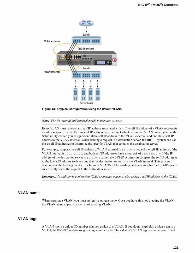
Figure 13: A typical configuration using the default VLANs
Note: VLANs internal and external reside in partition Common.
Every VLANmust have a static self IP address associated with it. The self IP address of a VLAN representsan address space, that is, the range of IP addresses pertaining to the hosts in that VLAN. When you ran theSetup utility earlier, you assigned one static self IP address to the VLAN external, and one static self IPaddress to the VLAN internal. When sending a request to a destination server, the BIG-IP system can usethese self IP addresses to determine the specific VLAN that contains the destination server.
For example, suppose the self IP address of VLAN external is 12.1.0.100, and the self IP address of theVLAN internal is 11.1.0.100, and both self IP addresses have a netmask of 255.255.0.0. If the IPaddress of the destination server is 11.1.0.20, then the BIG-IP system can compare the self IP addressesto the host’s IP address to determine that the destination server is in the VLAN internal. This process,combined with checking the ARP cache and a VLAN’s L2 forwarding table, ensures that the BIG-IP systemsuccessfully sends the request to the destination server.
Important: In addition to configuring VLAN properties, you must also assign a self IP address to the VLAN.
VLAN name
When creating a VLAN, you must assign it a unique name. Once you have finished creating the VLAN,the VLAN name appears in the list of existing VLANs.
VLAN tags
A VLAN tag is a unique ID number that you assign to a VLAN. If you do not explicitly assign a tag to aVLAN, the BIG-IP® system assigns a tag automatically. The value of a VLAN tag can be between 1 and
121
BIG-IP® TMOS®: Concepts
4094. Once you or the BIG-IP system assigns a tag to a VLAN, any message sent from a host in that VLANincludes this VLAN tag as a header in the message.
A VLAN tag is useful when an interface has multiple VLANs associated with it; that is, when the interfacesyou assigned to the VLAN are assigned as tagged interfaces. In this case, the BIG-IP system can read theVLAN tag in the header of a message to determine the specific VLAN in which the source or destinationhost resides.
Important: If the device connected to a BIG-IP system interface is another switch, the VLAN tag that youassign to the VLAN on the BIG-IP system interface must match the VLAN tag assigned to the VLAN on theinterface of the other switch.
Interface assignments
For each VLAN that you create, you must assign one or more BIG-IP® system interfaces to that VLAN,using the Interfaces setting.When you assign an interface to a VLAN, you indirectly control the hosts fromwhich the BIG-IP system interface sends or receives messages.
Tip: You can assign not only individual interfaces to the VLAN, but also trunks.
For example, if you assign interface 1.11 to VLAN A, and you then associate VLAN A with a virtual server,then the virtual server sends its outgoing traffic through interface 1.11, to a destination host in VLAN A.Similarly, when a destination host sends a message to the BIG-IP system, the host’s VLAN membershipdetermines the BIG-IP system interface that should receive the incoming traffic.
Each VLAN has a MAC address. The MAC address of a VLAN is the same MAC address of thelowest-numbered interface assigned to that VLAN.
The BIG-IP system supports two methods for sending and receiving messages through an interface that isa member of one or more VLANs. These twomethods are port-based access to VLANs and tag-based accessto VLANs. The method used by a VLAN is determined by the way that you add a member interface to aVLAN.
Port-based access to VLANs
With port-based access to VLANs, the BIG-IP® system accepts frames for a VLAN simply because theyare received on an interface that is a member of that VLAN. With this method, an interface is an untaggedmember of the VLAN. Frames sent out through untagged interfaces contain no tag in their header.
Port-based access to VLANs occurs when you add an interface to a VLAN as an untagged interface. Inthis case, the VLAN is the only VLAN that you can associate with that interface. This limits the interfaceto accepting traffic only from that VLAN, instead of frommultiple VLANs. If you want to give an interfacethe ability to accept and receive traffic for multiple VLANs, you add the same interface to each VLAN asa tagged interface.
Tag-based access to VLANs
With tag-based access to VLANs, the BIG-IP® system accepts frames for a VLAN because the frames havetags in their headers and the tag matches the VLAN identification number for the VLAN. An interface thataccepts frames containing VLAN tags is a tagged member of the VLAN. Frames sent out through taggedinterfaces contain a tag in their header.
122
VLANs and VLAN Groups
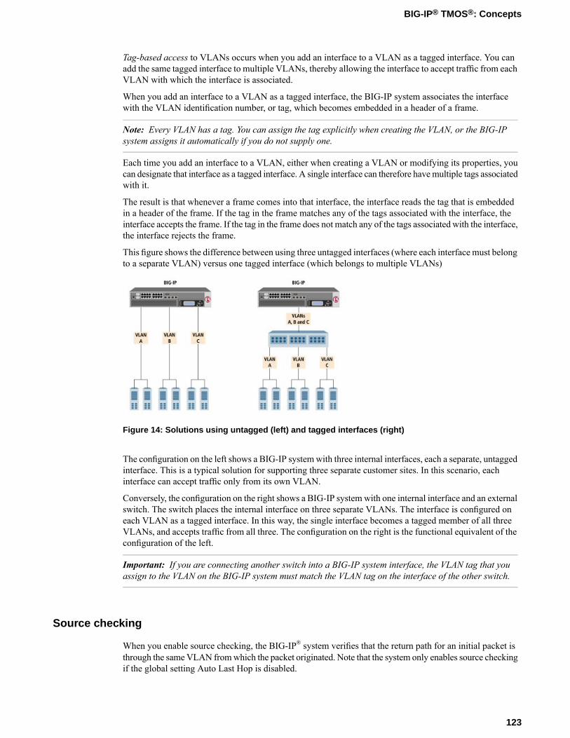
Tag-based access to VLANs occurs when you add an interface to a VLAN as a tagged interface. You canadd the same tagged interface to multiple VLANs, thereby allowing the interface to accept traffic from eachVLAN with which the interface is associated.
When you add an interface to a VLAN as a tagged interface, the BIG-IP system associates the interfacewith the VLAN identification number, or tag, which becomes embedded in a header of a frame.
Note: Every VLAN has a tag. You can assign the tag explicitly when creating the VLAN, or the BIG-IPsystem assigns it automatically if you do not supply one.
Each time you add an interface to a VLAN, either when creating a VLAN or modifying its properties, youcan designate that interface as a tagged interface. A single interface can therefore havemultiple tags associatedwith it.
The result is that whenever a frame comes into that interface, the interface reads the tag that is embeddedin a header of the frame. If the tag in the frame matches any of the tags associated with the interface, theinterface accepts the frame. If the tag in the frame does not match any of the tags associated with the interface,the interface rejects the frame.
This figure shows the difference between using three untagged interfaces (where each interface must belongto a separate VLAN) versus one tagged interface (which belongs to multiple VLANs)
Figure 14: Solutions using untagged (left) and tagged interfaces (right)
The configuration on the left shows a BIG-IP systemwith three internal interfaces, each a separate, untaggedinterface. This is a typical solution for supporting three separate customer sites. In this scenario, eachinterface can accept traffic only from its own VLAN.
Conversely, the configuration on the right shows a BIG-IP systemwith one internal interface and an externalswitch. The switch places the internal interface on three separate VLANs. The interface is configured oneach VLAN as a tagged interface. In this way, the single interface becomes a tagged member of all threeVLANs, and accepts traffic from all three. The configuration on the right is the functional equivalent of theconfiguration of the left.
Important: If you are connecting another switch into a BIG-IP system interface, the VLAN tag that youassign to the VLAN on the BIG-IP system must match the VLAN tag on the interface of the other switch.
Source checking
When you enable source checking, the BIG-IP® system verifies that the return path for an initial packet isthrough the sameVLAN fromwhich the packet originated. Note that the system only enables source checkingif the global setting Auto Last Hop is disabled.
123
BIG-IP® TMOS®: Concepts
Maximum transmission units
The value of the maximum transmission unit, or MTU, is the largest size that the BIG-IP® system allowsfor an IP datagram passing through a BIG-IP system interface. The default value is 1500.
VLAN-based fail-safe
VLAN fail-safe is a feature you enable when you want to base redundant-system failover on VLAN-relatedevents. To configure VLAN fail-safe, you specify a timeout value and the action that you want the systemto take when the timeout period expires.
Auto last hop
When you create a VLAN, you can designate the VLAN as the last hop for TMM traffic.
About the CMP hash setting
The CMP Hash setting allows all connections from a client system to use the same set of TMMs. Thisimproves system performance. In configuring the CMPHash value, you can choose the traffic disaggregationcriteria for the VLAN, either source IP address, destination IP address, or TCP/UDP source/destinationports. The default value uses TCP/UDP source/destination ports. Note that the CMP Hash setting appearsonly on the properties screen for an existing VLAN.
Maintaining the L2 forwarding table
Layer 2 forwarding is the means by which frames are exchanged directly between hosts, with no IP routingrequired. This is accomplished using a simple forwarding table for each VLAN. The L2 forwarding tableis a list that shows, for each host in the VLAN, the MAC address of the host, along with the interface thatthe BIG-IP® system needs for sending frames to that host. The intent of the L2 forwarding table is to helpthe BIG-IP system determine the correct interface for sending frames, when the system determines that norouting is required.
The format of an entry in the L2 forwarding table is:
<MAC address> -> <if>
For example, an entry for a host in the VLAN might look like this:
00:a0:c9:9e:1e:2f -> 2.1
The BIG-IP system learns the interfaces that correspond to various MAC entries as frames pass through thesystem, and automatically adds entries to the table accordingly. These entries are known as dynamic entries.You can also add entries to the table manually, and these are known as static entries. Entering static entriesis useful if you have network devices that do not advertise their MAC addresses. The system does notautomatically update static entries.
The BIG-IP system does not always need to use the L2 forwarding table to find an interface for frametransmission. For instance, if a VLAN has only one interface assigned to it, then the BIG-IP systemautomatically uses that interface.
124
VLANs and VLAN Groups
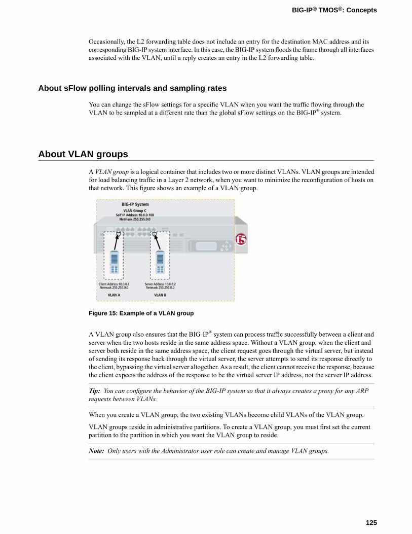
Occasionally, the L2 forwarding table does not include an entry for the destination MAC address and itscorresponding BIG-IP system interface. In this case, the BIG-IP system floods the frame through all interfacesassociated with the VLAN, until a reply creates an entry in the L2 forwarding table.
About sFlow polling intervals and sampling rates
You can change the sFlow settings for a specific VLAN when you want the traffic flowing through theVLAN to be sampled at a different rate than the global sFlow settings on the BIG-IP® system.
About VLAN groups
A VLAN group is a logical container that includes two or more distinct VLANs. VLAN groups are intendedfor load balancing traffic in a Layer 2 network, when you want to minimize the reconfiguration of hosts onthat network. This figure shows an example of a VLAN group.
Figure 15: Example of a VLAN group
A VLAN group also ensures that the BIG-IP® system can process traffic successfully between a client andserver when the two hosts reside in the same address space. Without a VLAN group, when the client andserver both reside in the same address space, the client request goes through the virtual server, but insteadof sending its response back through the virtual server, the server attempts to send its response directly tothe client, bypassing the virtual server altogether. As a result, the client cannot receive the response, becausethe client expects the address of the response to be the virtual server IP address, not the server IP address.
Tip: You can configure the behavior of the BIG-IP system so that it always creates a proxy for any ARPrequests between VLANs.
When you create a VLAN group, the two existing VLANs become child VLANs of the VLAN group.
VLAN groups reside in administrative partitions. To create a VLAN group, you must first set the currentpartition to the partition in which you want the VLAN group to reside.
Note: Only users with the Administrator user role can create and manage VLAN groups.
125
BIG-IP® TMOS®: Concepts
About VLAN group names
When creating a VLAN group, you must assign it a unique name. Once you have finished creating theVLAN group, the VLAN group name appears in the list of existing VLANs groups.
VLAN group ID
A VLAN group ID is a tag for the VLAN group. Every VLAN group needs a unique ID number. If you donot specify an ID for the VLAN group, the BIG-IP® system automatically assigns one. The value of a VLANgroup ID can be between 1 and 4094.
About transparency mode
The BIG-IP® system is capable of processing traffic using a combination of Layer 2 and Layer 3 forwarding,that is, switching and IP routing. When you set the transparency mode, you specify the type of forwardingthat the BIG-IP system performs when forwarding a message to a host in a VLAN. The default setting istranslucent, which means that the BIG-IP system uses a mix of Layer 2 and Layer 3 processing. The allowedvalues are:
opaqueA proxy ARP with Layer 3 forwarding
translucentLayer 2 forwarding with a locally-unique bit, toggled in ARP response across VLANs. This is the defaultsetting. When you choose this value and you have a virtual server that references a Fast L4 profile, theBIG-IP system automatically changes the PVA Acceleration setting to None
transparentLayer 2 forwarding with the original MAC address of the remote system preserved across VLANs.When you choose this value and you have a virtual server that references a Fast L4 profile, the BIG-IPsystem automatically changes the PVA Acceleration setting to None.
About traffic bridging
When you enable the traffic bridging option, you are instructing the VLAN group to forward all non-IPtraffic. Note that IP traffic is bridged by default. The default value for this setting is disabled (unchecked).
About traffic bridging with standby units
When enabled, the Bridge in Standby setting ensures that the VLAN group can forward packets when thesystem is the standby device of a redundant system configuration. Note that this setting applies to non-IPand non-ARP frames only, such as Bridge Protocol Data Units (BPDUs).
This setting is designed for deployments in which the VLAN group is defined on a redundant system. Youcan use the Bridge in Standby setting in transparent or translucent modes, or in opaque mode when theglobal variable Failover.Standby.LinkDownTime is set to 0.
126
VLANs and VLAN Groups

Warning: This setting can cause adverse effects if the VLAN group exists on more than one device in adevice group. The setting is intended for configurations where the VLAN group exists on one device only.The default setting is enabled (checked).
About host exclusion from proxy ARP forwarding
A host in a VLAN cannot normally communicate to a host in another VLAN. This rule applies to ARPrequests as well. However, if you put the VLANs into a single VLAN group, the BIG-IP® system canperform a proxied ARP request.
A proxied ARP request is an ARP request that the BIG-IP system can send, on behalf of a host in a VLAN,to hosts in another VLAN. A proxied ARP request requires that both VLANs belong to the same VLANgroup.
In some cases, you might not want a host to forward proxied ARP requests to a specific host, or to otherhosts in the configuration. To exclude specific hosts from receiving forwarded proxied ARP requests, youuse the Configuration utility and specify the IP addresses that you want to exclude.
Warning: Although hosts on an ARP exclusion list are specified using their IP addresses, this does notprevent the BIG-IP system from routing traffic to those hosts. A more secure way to prevent traffic frompassing between hosts in separate VLANs is to create a packet filter for each VLAN.
VLAN association with a self IP address
After you create a VLAN or a VLAN group, you must associate it with a self IP address. You associate aVLAN or VLAN group with a self IP address using the New Self IPs screens of the Configuration utility:
Associating a VLAN with a self IP addressThe self IP address with which you associate a VLAN should represent an address space that includesthe IP addresses of the hosts that the VLAN contains. For example, if the address of one host is 11.0.0.1and the address of the other host is 11.0.0.2, you could associate the VLAN with a self IP address of11.0.0.100, with a netmask of 255.255.255.0.
Associating a VLAN group with a self IP addressThe self IP address with which you associate a VLAN group should represent an address space thatincludes the self IP addresses of the VLANs that you assigned to the group. For example, if the addressof one VLAN is 10.0.0.1 and the address of the other VLAN is 10.0.0.2, you could associate theVLAN group with a self IP address of 10.0.0.100, with a netmask of 255.255.255.0.
VLAN assignment to route domains
If you explicitly create route domains, you should consider the following facts:
• You can assign VLANs (and VLAN groups) to route domain objects that you create. Traffic pertainingto that route domain uses those assigned VLANs,
• During BIG-IP® system installation, the system automatically creates a default route domain, with anID of 0. Route domain 0 has two VLANs assigned to it, VLAN internal and VLAN external.
127
BIG-IP® TMOS®: Concepts

• If you create one or more VLANs in an administrative partition other than Common, but do not create aroute domain in that partition, then the VLANs you create in that partition are automatically assignedto route domain 0.
Overview: Bridging VLAN and VXLAN networks
Large data centers and cloud service providers are benefiting from the use of Layer 2 over Layer 3 overlaynetworks to support large scale network virtualization. You can configure Virtual eXtended LAN (VXLAN)on a BIG-IP® system to enable a physical VLAN to communicate with virtual machines (VMs) in a virtualnetwork. The BIG-IP system becomes a gateway to bridge the data center virtual network with the physicalexternal network. Connecting these two networks allows for expansion, and provides a mechanism tostreamline the transition of data centers into a virtualized model, while maintaining connectivity.
Figure 16: The VXLAN gateway
When you configure a BIG-IP system as a VXLAN gateway, the system represents the VXLAN as a tunnel,which provides a Layer 2 interface on the virtual network. You can use the tunnel interface in both Layer2 and Layer 3 configurations. After you configure the VXLAN tunnel, the BIG-IP system joins the configuredmulticast group, and can forward both unicast and multicast or broadcast frames on the virtual network.The BIG-IP system learns aboutMAC address andVTEP associations dynamically, thus avoiding unnecessarytransmission of multicast traffic.
128
VLANs and VLAN Groups
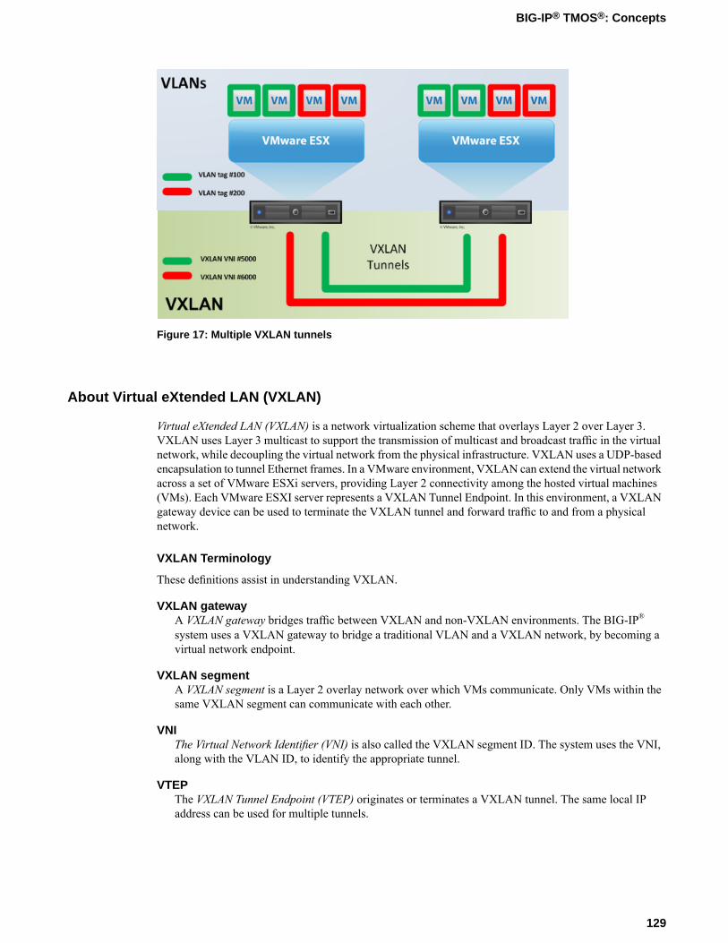
Figure 17: Multiple VXLAN tunnels
About Virtual eXtended LAN (VXLAN)
Virtual eXtended LAN (VXLAN) is a network virtualization scheme that overlays Layer 2 over Layer 3.VXLAN uses Layer 3 multicast to support the transmission of multicast and broadcast traffic in the virtualnetwork, while decoupling the virtual network from the physical infrastructure. VXLAN uses a UDP-basedencapsulation to tunnel Ethernet frames. In a VMware environment, VXLAN can extend the virtual networkacross a set of VMware ESXi servers, providing Layer 2 connectivity among the hosted virtual machines(VMs). Each VMware ESXI server represents a VXLAN Tunnel Endpoint. In this environment, a VXLANgateway device can be used to terminate the VXLAN tunnel and forward traffic to and from a physicalnetwork.
VXLAN Terminology
These definitions assist in understanding VXLAN.
VXLAN gatewayA VXLAN gateway bridges traffic between VXLAN and non-VXLAN environments. The BIG-IP®
system uses a VXLAN gateway to bridge a traditional VLAN and a VXLAN network, by becoming avirtual network endpoint.
VXLAN segmentA VXLAN segment is a Layer 2 overlay network over which VMs communicate. Only VMs within thesame VXLAN segment can communicate with each other.
VNIThe Virtual Network Identifier (VNI) is also called the VXLAN segment ID. The system uses the VNI,along with the VLAN ID, to identify the appropriate tunnel.
VTEPThe VXLAN Tunnel Endpoint (VTEP) originates or terminates a VXLAN tunnel. The same local IPaddress can be used for multiple tunnels.
129
BIG-IP® TMOS®: Concepts

VXLAN headerIn addition to the UDP header, encapsulated packets include a VXLAN header, which carries a 24-bitVNI to uniquely identify Layer 2 segments within the overlay.
130
VLANs and VLAN Groups

Chapter
19Failsafe
• About system fail-safe• About VLAN fail-safe• About gateway fail-safe
About system fail-safe
When you configure system fail-safe, the BIG-IP system monitors various hardware components, as wellas the heartbeat of various system services, and can take action if the system detects a heartbeat failure.
You can configure the BIG-IP system to monitor the switch board component and then take some action ifthe BIG-IP system detects a failure. Using the Configuration utility, you can specify the action that youwant the BIG-IP system to take when the component fails. Possible actions that the BIG-IP system can takeare:
• Reboot the BIG-IP system.• Restart all system services.• Go offline.• Go offline and cancel the TMM service.• Fail over and restart TMM.
You configure system fail-safe from the System > High Availability screen.
About VLAN fail-safe
For maximum reliability, the BIG-IP® system supports failure detection on all VLANs.When you configurethe fail-safe option for a VLAN, the BIG-IP system monitors network traffic going through that VLAN. Ifthe BIG-IP system detects a loss of traffic on the VLAN and the fail-safe timeout period has elapsed, theBIG-IP system attempts to generate traffic by issuing ARP requests to nodes accessible through the VLAN.The BIG-IP system also generates an ARP request for the default route, if the default router is accessiblefrom the VLAN. Failover is averted if the BIG-IP system is able to send and receive any traffic on theVLAN, including a response to its ARP request.
For a redundant system configuration, if the BIG-IP system does not receive traffic on the VLAN beforethe timeout period expires, the system can initiate failover to another device group member, reboot, or restartall system services. For a single device configuration, the system can either reboot or restart all systemservices. The default action for both configurations is Reboot.
Warning: You should configure the fail-safe option on a VLAN only after the BIG-IP system is in a stableproduction environment. Otherwise, routine network changes might cause failover unnecessarily.
Each interface card installed on the BIG-IP system is typically mapped to a different VLAN. Thus, whenyou set the fail-safe option on a particular VLAN, you need to know the interface to which the VLAN ismapped. You can use the BIG-IP Configuration utility to viewVLAN names and their associated interfaces.
There are two ways to configure VLAN fail-safe in the BIG-IP Configuration utility: from the System >High Availability > VLANs > Add VLAN screen or from the Network > VLANs > New VLAN screen.
About gateway fail-safe
One type of network failure detection is known as gateway fail-safe, which applies to redundant systemconfigurations only.Gateway fail-safemonitors traffic between an active BIG-IP® system in a device groupand a pool containing a gateway router. You configure the gateway fail-safe feature if you want the BIG-IP
132
Failsafe
system to take an action, such as failover, whenever some number of gateway routers in a pool of routersbecomes unreachable.
You can configure gateway fail-safe using the BIG-IP Configuration utility. Configuring gateway fail-safemeans designating a pool of routers as a gateway fail-safe pool. When you designate a pool as a gatewayfail-safe pool, you provide the following information:
• The name of the pool• The name of a BIG-IP device in a device group (either the local device or any other device groupmember)• The minimum number of gateway pool members that must be available to avoid the designated action• The action that the BIG-IP system should take when the number of available gateway pool members
drops below the designated threshold. The default value is Failover.
After you configure gateway fail-safe, specifying an action of Failover, the named BIG-IP device (and onlythat device) fails over to another device group member whenever the number of available pool membersfalls below the specified threshold. Although all device group members share their pool configurations,each device ignores any gateway fail-safe configuration that does not specify itself as the device associatedwith the specified gateway pool.
You configure gateway fail-safe from the System > High Availability > Fail-safe > Gateway screen.
133
BIG-IP® TMOS®: Concepts


Index
A
access leveldefinition 57enable/disable 57read 57update 57write 57
action settingfor packet filter rules 89
address spacedefinition 82
admin accountconfiguration of 57password 57
administrative account passwords 35administrative accounts
creation of 52administrative boundaries
setting 45administrative partition
assign partition access 46create user accounts 46definition 53
administrative partition Common 44administrative partitions
definition 44setting current 45
AOMand console output 22
archivebackup 38propagate data 38restoration 39saving 38
audit logging73
disabling 74enabling 74
audit user access 67authentication
level 27authentication lockout 60authorization
for groups of user accounts 66remote account 64
auto last hop 124automatic link selection 117
B
base rate 93base throughput rate 93BIG-IP system
description 19BIG-IP system services
managing 42
boundaries, administrativesetting 45
bridge 102bridge priority
for spanning tree 106burst reservoir
depleting 94replenishing 94
burst size 93–94
C
ceiling rate 93certificate chain 27CMP Hash setting
for VLANs 124code expansion
syslog messages 73configuration properties 22console output
saving 22current partition 45
D
data group filesaddress 30example 30integer 30string 30
delete local user account 62device certificate 26device properties 22DHCP protocol 23DHCP server 23distribution function
for frames 118DNS 23Domain Name System 23drop policy 97
E
edge port 108enforcement restriction 58external file management
data group files 30iFiles 30
external monitor program file 30
F
fail-safeand VLANs 124, 132for gateway pools 132for system daemons 132
135
Index

filter expressionabout creation 90definition 90
flow control property 78folders
defined 50object naming 50object referencing 50relationship with partitions 50
forward delay option 103frames
distributing 118transmitting 118
G
Gateway fail-safe 132general properties
host IP address 34host name 34management port and TMM 34management port configuration 34time zone 34
global exemptionsfor IP address 88for MAC address 88for protocol 87for VLAN 87–88
global propertiescontrolling unhandled packets 86enabling packet filter 86options 86
global timer 103global timers 103granular synchronization
with folders 50
H
hello time option 103
I
iFiles 30individual user account
authorization 65instance ID 106instance member
defined 107interface ID
viewing 109interface mirroring
definition 79interface name
example 77interface naming conventions 77interface priority 110interface setting 115invalid object referencing 45IP address 88IP geolocation 22
L
LACPand timeout 116enabling 116overview 115
LACP mode 116Layer 2 forwarding table
maintaining 124link aggregation control protocol 115link layer discovery protocol
about 76link selection policy
and auto option 117and maximum bandwidth 117–118automatic 117
LLDPabout 76neighbor settings 79property 79
LLDP attributesabout 79
local area network 120local syslog logging 72local traffic
properties 23local user account
creation 60delete 62management of 57modification 62view 61
loggingaudit 73–74code expansion 73level setting 72local storage 71local syslog 72local traffic events 73message types 70overview 70packet filter events 73remote 74remote storage 70syslog 73syslog-ng 74system events 73
log levelsetting 72
log level setting 72log message
remote storage 70log messages
90local storage 71
M
MAC addressand packet filtering 88and self IP addresses 82
136
Index

maximum age optiondefault 103valid range 103
maximum bandwidthfor link selection policy 118
maximum transmission unitsand default value 124
MCP audit loggingdefinition 74
MSTP 101MSTP global properties 104MTU
and default value 124
N
neighbor settingsLLDP 79
Network Time Protocol 23NTP 23
O
object name 50object referencing
45between folders 50
overlay networksusing VXLAN 129
P
packet filteringabout 86global settings 86
packet filter rulesabout 86and action setting 89for VLANs 90logging 90ordering 89
parent class 96partition
Common 50relationship with folders 50
partition access 66partition Common 44–45partitions
setting current 45password
administrative account 35password policy restrictions 58path cost 110pause frame
definition 78platform properties 34policy
for link selection 117policy restriction 58polling interval
on VLANs for sFlow 125
port-based accessto VLANs 122
port rolesfor spanning tree instance 109
port statesblocking 110forwarding 110learning 110
protocol degradation 101protocols setting 87proxied ARP requests
and VLAN groups 127
Q
queue method settingusing priority FIFO 96using stochastic fair queue 96
R
rate classabout 92and queue method 96
rate class name 93rate class setting 90rate shaping
and base rate 93and burst size 93–94and ceiling rate 93and direction setting 95and parent class 96and policy 96definition 92
redundant device properties 35remote account
authorization 64remote authentication server 63remote user account
management 63server specification 63
remote user accountsauthorization 64default 64viewing 67
root bridge 106route domains
and VLAN assignment 127RSTP 100
S
sampling rateon VLANs for sFlow 125
secure network address translation 83secure password policy configuration
enforcement 58policy 58restrictions 58
secure sockets layer 26self IP address
and MAC addresses 82
137
Index

self IP address (continued)and VLAN 82definition 82properties 83purpose 82types defined 82
serial console outputsaving 22
server specificationremote user account 63
sFlowand VLANs 125
shaping policy 96SNAT
automapping 83source checking
for VLANs 123spanning tree
deleting an instance for MSTP 107spanning tree instance
modifying 107viewing 107
spanning tree instancescreating MSTP 105listing 105managing 104
spanning tree modedisabled 102MSTP 102pass through 102RSTP 102STP 102
spanning tree protocol resetabout 109
spanning tree protocolsand global timers 103and legacy bridges 101and link type 108and MSTP 101and RSTP 100and STP edge port 108configuration 102definition 100managing interface 109
SSH access configuration 35SSL certificate file 31SSL certificates 26standard user account 52STP
managing 108STP edge port
detecting 108setting 108
syslogexisting configuration 70local logging 72log messages 73
syslog-ngremote logging 74
system fail-safe 132system interface management
about 76
system interface propertiesabout 77about LLDP 79Fixed Requested Media 78flow control 78interface naming conventions 77interface state 78LLDP Attributes 79viewing 78
system interfacesand related configuration tasks 80and TMM switch 76and trunk feature 80assigning to VLAN 80definition 76for STP 107for VLAN 122mirroring 76viewing 78
system interface state 78system maintenance account 52
T
tag-based accessto VLANs 122
throughput policy 92timeout
value for LACP 116TMOS
configuration properties 22tmsh
and logging 74traffic bridging
and standby units 126and VLAN groups 126
transmit hold count option 104transparency mode
opaque 126translucent 126transparent 126
trunksand interface 115and LACP 115and link aggregation 114and name 115explained 114
U
user accessaudit 67
user accountsadministrative access 53authorization 64authorization for groups 66creation of 52group authorization 66individual authorization 65management of 52operator role 53partition access property 53
138
Index

user accounts (continued)partitioned object 46remote 63–64standard 52system maintenance 52to control access 54types 52
user administration properties 35user authentication lockout 60user manager role 61user roles
access level 57administrative 54administrator 56default 56definition 54described 54for local accounts 60no access 56permissions 54root 56
V
valid object referencing 45Virtual eXtended LAN, See VXLANvirtual local area network 120VLAN ++
and system interfaces 122VLAN-based fail-safe 124VLAN behavior
on the BIG-IP system 120
VLAN configurationand external 120and internal 120
VLAN fail-safe 132VLAN group ID 126VLAN group names 126VLAN groups
about 125and proxied ARP requests 127
VLAN name 121VLANs
and fail-safe 124and group self IP address 127and name 121and packet filtering 90and port-based access 122and route domain 127and self IP address 127and source checking 123and tag-based access 122and tags 121as last hop 124as STP instance 107
VLAN settingand packet filter 88
VLAN tags 121VXLAN
about 129bridging with L2 VLAN network 128configuring BIG-IP system as gateway 128overview 128terminology defined 129
139
Index

140
Index