biga series - peeconpeecon.com/documenten/biga_eco_serie_rev2.4.1_en.pdf · 10 introduction 1.4...
TRANSCRIPT

Peeters Landbouwmachines B.V.Tel +31 (0)76-504 66 66 Munnikenheiweg 47 www.peetersgroup.com
Fax +31 (0)76-504 66 99 4876NE Etten-Leur (NL) [email protected]
English
Biga SeriesFeed mixer type; Eco, Eco low, Twin eco, Twin eco wide body, Mammoet
OPERATOR'S MANUAL, 2015 REVISED 2.4.1
Store this document for future use! The main function of this document
is creating safe and efficient man/machine interaction.

2

3
© Copyright 2015
All rights reserved. No part of this publication may be reproduced, stored in or introduced into a retrieval system, or transmitted, in any form or by any means, electronic, mechanical, by photocopying, recording or otherwise, without the prior written permission of Peeters Landbouwmachines B.V. This also applies to the accompanying drawings and schedules.
Peeters Landbouwmachines B.V. reserves the right to change parts at any time, without prior or direct notification to the buyer.
The contents of this operator's manual may also be changed without prior notification. Please contact your supplier's technical service department for any information about settings, maintenance work or repairs which are not provided for in this operator's manual.
Although this operator's manual has been drawn up with all due care, Peeters Landbouwmachines B.V. does not assume any liability for any errors in this operator's manual or any consequences thereof.

4

5
PrefaceThe aim of this operator's manual is to give users an understanding of the operation, assembly and maintenance of the machines supplied by Peeters Landbouwmachines B.V. Thoroughly read these instructions before starting to use this machine and follow these instructions at all times. When in doubt about how to perform an action, please contact Peeters Landbouwmachines B.V. Installation, commissioning and maintenance must only be carried out by experience technicians.
As this concerns industrial equipment, we assume it is installed and maintained by properly trained and educated technicians. Peeters Landbouwmachines B.V. has paid a lot of attention to the safety and reliability of the machine and the accompanying installation. Some safety measures have been taken to ensure that the equipment can be worked with safely. When coupling and/or connecting the machine, all safety components must be installed before putting the machine into use.

6
7
Table of contents1 Introduction . . . . . . . . . . . . . . . . . . . . . . . . . . . . . . . . . . . . . . . . . . . . . . . . . . . . . . . . . . . . . . . . . . . . . . . . . 9
1.1 General . . . . . . . . . . . . . . . . . . . . . . . . . . . . . . . . . . . . . . . . . . . . . . . . . . . . . . . . . . . . . . . . . . . . . . . . . 91.2 Goal . . . . . . . . . . . . . . . . . . . . . . . . . . . . . . . . . . . . . . . . . . . . . . . . . . . . . . . . . . . . . . . . . . . . . . . . . . . . 91.3 Intended user . . . . . . . . . . . . . . . . . . . . . . . . . . . . . . . . . . . . . . . . . . . . . . . . . . . . . . . . . . . . . . . . . . . . 91.2 Technical Specifications Biga series . . . . . . . . . . . . . . . . . . . . . . . . . . . . . . . . . . . . . . . . . . . . . . . . . . 101.6 Elementary specifications . . . . . . . . . . . . . . . . . . . . . . . . . . . . . . . . . . . . . . . . . . . . . . . . . . . . . . . . . . 201.10 Main elements . . . . . . . . . . . . . . . . . . . . . . . . . . . . . . . . . . . . . . . . . . . . . . . . . . . . . . . . . . . . . . . . . 211.17 Marking conventions . . . . . . . . . . . . . . . . . . . . . . . . . . . . . . . . . . . . . . . . . . . . . . . . . . . . . . . . . . . . . 361.20 Main label of your machine . . . . . . . . . . . . . . . . . . . . . . . . . . . . . . . . . . . . . . . . . . . . . . . . . . . . . . . 371.25 Markings on hydraulic hoses . . . . . . . . . . . . . . . . . . . . . . . . . . . . . . . . . . . . . . . . . . . . . . . . . . . . . . . 381.26 Liability and guarantee . . . . . . . . . . . . . . . . . . . . . . . . . . . . . . . . . . . . . . . . . . . . . . . . . . . . . . . . . . . 38
3 Making your machine ready for use . . . . . . . . . . . . . . . . . . . . . . . . . . . . . . . . . . . . . . . . . . . . . . . . . . . . . 393.1 General . . . . . . . . . . . . . . . . . . . . . . . . . . . . . . . . . . . . . . . . . . . . . . . . . . . . . . . . . . . . . . . . . . . . . . . . 393.2 Storing the machine . . . . . . . . . . . . . . . . . . . . . . . . . . . . . . . . . . . . . . . . . . . . . . . . . . . . . . . . . . . . . . 393.3 First time coupling of your feed mixer to your tractor . . . . . . . . . . . . . . . . . . . . . . . . . . . . . . . . . . . . 39
7 Safety instructions . . . . . . . . . . . . . . . . . . . . . . . . . . . . . . . . . . . . . . . . . . . . . . . . . . . . . . . . . . . . . . . . . . . 417.1 General . . . . . . . . . . . . . . . . . . . . . . . . . . . . . . . . . . . . . . . . . . . . . . . . . . . . . . . . . . . . . . . . . . . . . . . . 4112.2 Danger zone . . . . . . . . . . . . . . . . . . . . . . . . . . . . . . . . . . . . . . . . . . . . . . . . . . . . . . . . . . . . . . . . . . . 4412.6 Coupling and uncoupling the machine . . . . . . . . . . . . . . . . . . . . . . . . . . . . . . . . . . . . . . . . . . . . . . . 4512.7 Using the machine . . . . . . . . . . . . . . . . . . . . . . . . . . . . . . . . . . . . . . . . . . . . . . . . . . . . . . . . . . . . . . 4512.8 Safety symbols . . . . . . . . . . . . . . . . . . . . . . . . . . . . . . . . . . . . . . . . . . . . . . . . . . . . . . . . . . . . . . . . . 4612.12 Brake system . . . . . . . . . . . . . . . . . . . . . . . . . . . . . . . . . . . . . . . . . . . . . . . . . . . . . . . . . . . . . . . . . 5312.13 Extreme situations . . . . . . . . . . . . . . . . . . . . . . . . . . . . . . . . . . . . . . . . . . . . . . . . . . . . . . . . . . . . . 53
14 Function description . . . . . . . . . . . . . . . . . . . . . . . . . . . . . . . . . . . . . . . . . . . . . . . . . . . . . . . . . . . . . . . . . 5414.1 Coupling the machine . . . . . . . . . . . . . . . . . . . . . . . . . . . . . . . . . . . . . . . . . . . . . . . . . . . . . . . . . . . . 5414.2 Loading the machine . . . . . . . . . . . . . . . . . . . . . . . . . . . . . . . . . . . . . . . . . . . . . . . . . . . . . . . . . . . . 5416.2 Mixing the feed. . . . . . . . . . . . . . . . . . . . . . . . . . . . . . . . . . . . . . . . . . . . . . . . . . . . . . . . . . . . . . . . . 5516.3 Unloading feed . . . . . . . . . . . . . . . . . . . . . . . . . . . . . . . . . . . . . . . . . . . . . . . . . . . . . . . . . . . . . . . . . 5616.4 Parking the feed mixer . . . . . . . . . . . . . . . . . . . . . . . . . . . . . . . . . . . . . . . . . . . . . . . . . . . . . . . . . . . 5616.5 Recommended loading sequence . . . . . . . . . . . . . . . . . . . . . . . . . . . . . . . . . . . . . . . . . . . . . . . . . . . 57
18 Maintenance and inspection . . . . . . . . . . . . . . . . . . . . . . . . . . . . . . . . . . . . . . . . . . . . . . . . . . . . . . . . . . 5818.1 General . . . . . . . . . . . . . . . . . . . . . . . . . . . . . . . . . . . . . . . . . . . . . . . . . . . . . . . . . . . . . . . . . . . . . . . 5820.2 General inspection . . . . . . . . . . . . . . . . . . . . . . . . . . . . . . . . . . . . . . . . . . . . . . . . . . . . . . . . . . . . . . 5920.3 Daily inspection . . . . . . . . . . . . . . . . . . . . . . . . . . . . . . . . . . . . . . . . . . . . . . . . . . . . . . . . . . . . . . . . . 5920.4 Weekly maintenance items . . . . . . . . . . . . . . . . . . . . . . . . . . . . . . . . . . . . . . . . . . . . . . . . . . . . . . . 5920.5 Monthly maintenance items . . . . . . . . . . . . . . . . . . . . . . . . . . . . . . . . . . . . . . . . . . . . . . . . . . . . . . . 6020.6 Annual maintenance items . . . . . . . . . . . . . . . . . . . . . . . . . . . . . . . . . . . . . . . . . . . . . . . . . . . . . . . . 6020.7 After commissioning . . . . . . . . . . . . . . . . . . . . . . . . . . . . . . . . . . . . . . . . . . . . . . . . . . . . . . . . . . . . . 6020.8 Decommissioning for more than 1 month . . . . . . . . . . . . . . . . . . . . . . . . . . . . . . . . . . . . . . . . . . . . 6020.9 Torques . . . . . . . . . . . . . . . . . . . . . . . . . . . . . . . . . . . . . . . . . . . . . . . . . . . . . . . . . . . . . . . . . . . . . . . 6020.8 Maintenance of the optional brake system . . . . . . . . . . . . . . . . . . . . . . . . . . . . . . . . . . . . . . . . . . . 6120.9 Lubricants. . . . . . . . . . . . . . . . . . . . . . . . . . . . . . . . . . . . . . . . . . . . . . . . . . . . . . . . . . . . . . . . . . . . . . 61

8
20.10 Renewing gearbox oil . . . . . . . . . . . . . . . . . . . . . . . . . . . . . . . . . . . . . . . . . . . . . . . . . . . . . . . . . . . 6120.11 Topping up oil in the lubrication system . . . . . . . . . . . . . . . . . . . . . . . . . . . . . . . . . . . . . . . . . . . . . 6120.11 Lubrication points . . . . . . . . . . . . . . . . . . . . . . . . . . . . . . . . . . . . . . . . . . . . . . . . . . . . . . . . . . . . . . 62
22 Glossary . . . . . . . . . . . . . . . . . . . . . . . . . . . . . . . . . . . . . . . . . . . . . . . . . . . . . . . . . . . . . . . . . . . . . . . . . . 6326 Troubleshooting list . . . . . . . . . . . . . . . . . . . . . . . . . . . . . . . . . . . . . . . . . . . . . . . . . . . . . . . . . . . . . . . . . 64
26.1 Mechanical/ hydraulic fault . . . . . . . . . . . . . . . . . . . . . . . . . . . . . . . . . . . . . . . . . . . . . . . . . . . . . . . 6426.2 Electrical fault . . . . . . . . . . . . . . . . . . . . . . . . . . . . . . . . . . . . . . . . . . . . . . . . . . . . . . . . . . . . . . . . . . 64
30 System diagrams . . . . . . . . . . . . . . . . . . . . . . . . . . . . . . . . . . . . . . . . . . . . . . . . . . . . . . . . . . . . . . . . . . . 6530.1 Hydraulic system . . . . . . . . . . . . . . . . . . . . . . . . . . . . . . . . . . . . . . . . . . . . . . . . . . . . . . . . . . . . . . . . 6532.2 Electrical system . . . . . . . . . . . . . . . . . . . . . . . . . . . . . . . . . . . . . . . . . . . . . . . . . . . . . . . . . . . . . . . . 6632.3 Electrical system . . . . . . . . . . . . . . . . . . . . . . . . . . . . . . . . . . . . . . . . . . . . . . . . . . . . . . . . . . . . . . . . 67

9
Introduction
1 Introduction1.1 General
We would like to start by congratulating you on purchasing your new Peecon Biga feed mixer. Peecon products are synonymous with quality and reliability.
The Peecon Biga series was developed following an intensive research and test programme. One of our initial objectives was and is constructing machines whose use, operation, safety, maintenance and service life comply with, at a minimum, all the latest available standards and regulations of the EEC. Peecon machines can be delivered in various different versions; your version is described in section 1.4. The possibility to indicate your options has been created so that you will always refer to the right version.
1.2 Goal
The objective of the operating instructions in this manual is to give you the right information regarding how to carry out these actions. This document is part of the machine and it must always be available at the machine / on the tractor.
The Peecon Biga model is available in many different “standard” versions and with a wide range of extras to enable you to expand your feed mixer to a machine tailored to your specific requirements. The Peecon Biga model can be used for mixing and, if necessary, cutting various kinds of produce. It can also be used to transport and dispense feed to livestock. The Biga model has been fully equipped according to your wishes in order to enable comfortable working for many hours and in heavy-duty conditions.
We understand that you are keen to start using your feed mixer, but please take some time to first read these instructions carefully. Every Peecon feed mixer is one of a kind. This may lead to dangers if you do not use the feed mixer in the correct way. Thoroughly reading this operator’s manual may save you time and money in the future. Any use other than that described in these instructions cancels any liability on the part of your supplier.
1.3 Intended user
This operator's manual is intended for authorised personnel and technically competent personnel.
Authorised personnel are people who:have achieved a certain level of knowledge through education / training (internal training course specifically for the feed mixer) and have certain skills to operate the machine.
Technically competent personnel are people who:are authorised and have developed a certain level of technical expertise (at least an diploma at intermediate vocational education level) through schooling / training and who are familiar with the machine's technology and aware of the possible dangers and risks. They are also authorised to set up the machine, to work with the machine, to clean it and to carry out maintenance work. (e.g. a Peeters Landbouwmachines B.V. service technician)
10
Introduction
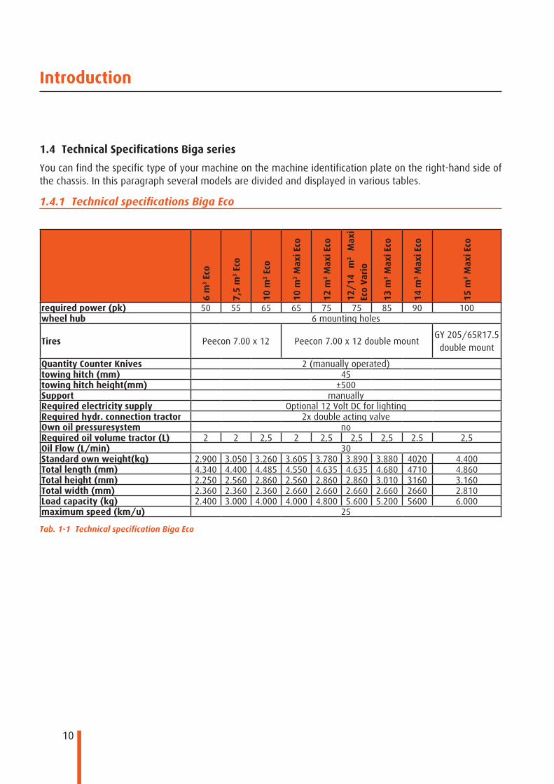
1.4 Technical Specifications Biga series
You can find the specific type of your machine on the machine identification plate on the right-hand side of the chassis. In this paragraph several models are divided and displayed in various tables.
1.4.1 Technical specifications Biga Eco6
m3
Eco
7,5
m3
Eco
10 m
3 Ec
o
10 m
3 M
axi E
co
12 m
3 M
axi E
co
12/
14
m3
Max
i Ec
o Va
rio
13 m
3 M
axi E
co
14 m
3 M
axi E
co
15 m
3 M
axi E
co
required power (pk) 50 55 65 65 75 75 85 90 100wheel hub 6 mounting holes
Tires Peecon 7.00 x 12 Peecon 7.00 x 12 double mountGY 205/65R17.5 double mount
Quantity Counter Knives 2 (manually operated)towing hitch (mm) 45towing hitch height(mm) ±500Support manuallyRequired electricity supply Optional 12 Volt DC for lightingRequired hydr. connection tractor 2x double acting valveOwn oil pressuresystem noRequired oil volume tractor (L) 2 2 2,5 2 2,5 2,5 2,5 2.5 2,5Oil Flow (L/min) 30Standard own weight(kg) 2.900 3.050 3.260 3.605 3.780 3.890 3.880 4020 4.400Total length (mm) 4.340 4.400 4.485 4.550 4.635 4.635 4.680 4710 4.860Total height (mm) 2.250 2.560 2.860 2.560 2.860 2.860 3.010 3160 3.160Total width (mm) 2.360 2.360 2.360 2.660 2.660 2.660 2.660 2660 2.810Load capacity (kg) 2.400 3.000 4.000 4.000 4.800 5.600 5.200 5600 6.000maximum speed (km/u) 25
Tab. 1-1 Technical specification Biga Eco
11
Introduction
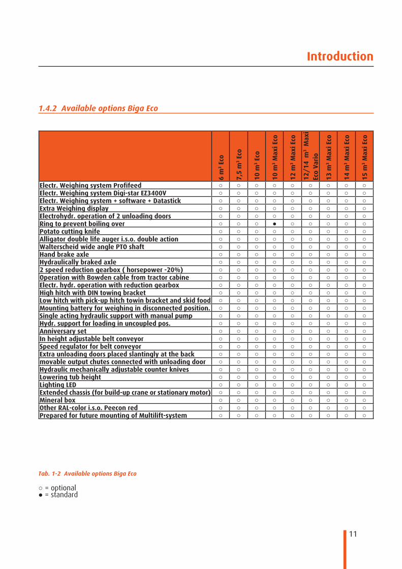
○ = optional● = standard
1.4.2 Available options Biga Eco
Tab. 1-2 Available options Biga Eco
6 m
3 Ec
o
7,5
m3
Eco
10 m
3 Ec
o
10 m
3 M
axi E
co
12 m
3 M
axi E
co
12/
14 m
3 M
axi
Eco
Vari
o
13 m
3 M
axi E
co
14 m
3 M
axi E
co
15 m
3 M
axi E
co
Electr. Weighing system Profifeed ○ ○ ○ ○ ○ ○ ○ ○ ○Electr. Weighing system Digi-star EZ3400V ○ ○ ○ ○ ○ ○ ○ ○ ○Electr. Weighing system + software + Datastick ○ ○ ○ ○ ○ ○ ○ ○ ○Extra Weighing display ○ ○ ○ ○ ○ ○ ○ ○ ○Electrohydr. operation of 2 unloading doors ○ ○ ○ ○ ○ ○ ○ ○ ○Ring to prevent boiling over ○ ○ ○ ● ○ ○ ○ ○ ○Potato cutting knife ○ ○ ○ ○ ○ ○ ○ ○ ○Alligator double life auger i.s.o. double action ○ ○ ○ ○ ○ ○ ○ ○ ○Walterscheid wide angle PTO shaft ○ ○ ○ ○ ○ ○ ○ ○ ○Hand brake axle ○ ○ ○ ○ ○ ○ ○ ○ ○Hydraulically braked axle ○ ○ ○ ○ ○ ○ ○ ○ ○2 speed reduction gearbox ( horsepower -20%) ○ ○ ○ ○ ○ ○ ○ ○ ○Operation with Bowden cable from tractor cabine ○ ○ ○ ○ ○ ○ ○ ○ ○Electr. hydr. operation with reduction gearbox ○ ○ ○ ○ ○ ○ ○ ○ ○High hitch with DIN towing bracket ○ ○ ○ ○ ○ ○ ○ ○ ○Low hitch with pick-up hitch towin bracket and skid food ○ ○ ○ ○ ○ ○ ○ ○ ○Mounting battery for weighing in disconnected position. ○ ○ ○ ○ ○ ○ ○ ○ ○Single acting hydraulic support with manual pump ○ ○ ○ ○ ○ ○ ○ ○ ○Hydr. support for loading in uncoupled pos. ○ ○ ○ ○ ○ ○ ○ ○ ○Anniversary set ○ ○ ○ ○ ○ ○ ○ ○ ○In height adjustable belt conveyor ○ ○ ○ ○ ○ ○ ○ ○ ○Speed regulator for belt conveyor ○ ○ ○ ○ ○ ○ ○ ○ ○Extra unloading doors placed slantingly at the back ○ ○ ○ ○ ○ ○ ○ ○ ○movable output chutes connected with unloading door ○ ○ ○ ○ ○ ○ ○ ○ ○Hydraulic mechanically adjustable counter knives ○ ○ ○ ○ ○ ○ ○ ○ ○Lowering tub height ○ ○ ○ ○ ○ ○ ○ ○ ○Lighting LED ○ ○ ○ ○ ○ ○ ○ ○ ○Extended chassis (for build-up crane or stationary motor) ○ ○ ○ ○ ○ ○ ○ ○ ○Mineral box ○ ○ ○ ○ ○ ○ ○ ○ ○Other RAL-color i.s.o. Peecon red ○ ○ ○ ○ ○ ○ ○ ○ ○Prepared for future mounting of Multilift-system ○ ○ ○ ○ ○ ○ ○ ○ ○

12
Introduction
1.4.3 Technical specifications Biga Eco Low
6 m
3 Ec
o Lo
w
7,5
m3
Eco
Low
10 m
3 Ec
o Lo
w
10 m
3 Max
i Eco
Low
12 m
3 Max
i Eco
Low
13 m
3 Max
i Eco
Low
14 m
3 Max
i Eco
Low
15 m
3 Max
i Eco
Low
required power (pk) 50 55 65 65 75 85 90 100wheel hub 6 mounting holes
Tires Peecon 7.00 x 12 Peecon 7.00 x 12 double mountGoodyear
205/65R17.5 double mount
Quantity Counter Knives 2 (manually operated)towing hitch (mm) 45towing hitch height(mm) ±500Support manuallyRequired electricity supply Optional 12 Volt DC for lightingRequired hydr. connection tractor 2x double acting valveOwn oil pressuresystem noRequired oil volume tractor (L) 2 2 2,5 2 2,5 2,5 2,5 2,5Oil Flow (L/min) 30Standard own weight(kg) 3150 3300 3500 4000 4175 4275 4415 4.400Total length (mm) 4860 4860 4860 4950 4950 4950 4980 5090Total height (mm) 2100 2360 2650 2360 2650 2.800 2950 2900Total width (mm) 2.360 2.360 2.360 2.660 2.660 2.660 2.660 2.810Load capacity (kg) 2.400 3.000 4.000 4.000 4.800 5.200 5.600 6.000maximum speed (km/u) 25
Tab. 1-3 Technical specifications Biga Eco Low

13
Introduction
6 m
3 Ec
o Lo
w
7,5
m3
Eco
Low
10 m
3 Ec
o Lo
w
10 m
3 Max
i Eco
Low
12 m
3 Max
i Eco
Low
13 m
3 Max
i Eco
Low
14 m
3 Max
i Eco
Low
15 m
3 Max
i Eco
Low
Electr. Weighing system Profifeed ○ ○ ○ ○ ○ ○ ○ ○Electr. Weighing system Digi-star EZ3400V ○ ○ ○ ○ ○ ○ ○ ○Electr. Weighing system + software + Datastick ○ ○ ○ ○ ○ ○ ○ ○Extra Weighing display ○ ○ ○ ○ ○ ○ ○ ○Electrohydr. operation of 2 unloading doors ○ ○ ○ ○ ○ ○ ○ ○Ring to prevent boiling over ○ ○ ○ ● ○ ○ ○ ○Potato cutting knife ○ ○ ○ ○ ○ ○ ○ ○Alligator double life auger i.s.o. double action ○ ○ ○ ○ ○ ○ ○ ○Walterscheid wide angle PTO shaft ○ ○ ○ ○ ○ ○ ○ ○Hand brake axle ○ ○ ○ ○ ○ ○ ○ ○Hydraulically braked axle ○ ○ ○ ○ ○ ○ ○ ○Axle in 2 segments for shorter wheelbase of 250mm ○ ○ ○ ○ ○ ○ ○ ○2 speed reduction gearbox ( horsepower -20%) ○ ○ ○ ○ ○ ○ ○ ○Operation with Bowden cable from tractor cabine ○ ○ ○ ○ ○ ○ ○ ○Electr. hydr. operation with reduction gearbox ○ ○ ○ ○ ○ ○ ○ ○High hitch with DIN towing bracket ○ ○ ○ ○ ○ ○ ○ ○Low hitch with pick-up hitch towin bracket and skid food ○ ○ ○ ○ ○ ○ ○ ○Mounting battery for weighing in disconnected position. ○ ○ ○ ○ ○ ○ ○ ○Single acting hydraulic support with manual pump ○ ○ ○ ○ ○ ○ ○ ○Hydr. support for loading in uncoupled pos. ○ ○ ○ ○ ○ ○ ○ ○Anniversary set ○ ○ ○ ○ ○ ○ ○ ○Belt conveyor at the front of the machine ○ ○ ○ ○ ○ ○ ○ ○Speed regulator for belt conveyor ○ ○ ○ ○ ○ ○ ○ ○Extra unloading doors placed slantingly at the back ○ ○ ○ ○ ○ ○ ○ ○movable output chutes connected with unloading door ○ ○ ○ ○ ○ ○ ○ ○Hydraulic mechanically adjustable counter knives ○ ○ ○ ○ ○ ○ ○ ○Lowering tub height ○ ○ ○ ○ ○ ○ ○ ○Lighting LED ○ ○ ○ ○ ○ ○ ○ ○Extended chassis (for build-up crane or stationary motor) ○ ○ ○ ○ ○ ○ ○ ○Mineral box ○ ○ ○ ○ ○ ○ ○ ○Other RAL-color i.s.o. Peecon red ○ ○ ○ ○ ○ ○ ○ ○Prepared for future mounting of Multilift-system ○ ○ ○ ○ ○ ○ ○ ○
○ = optional● = standard
1.4.4 Available options Biga Eco Low
Tab. 1-4 Available options Biga Eco Low
14
Introduction
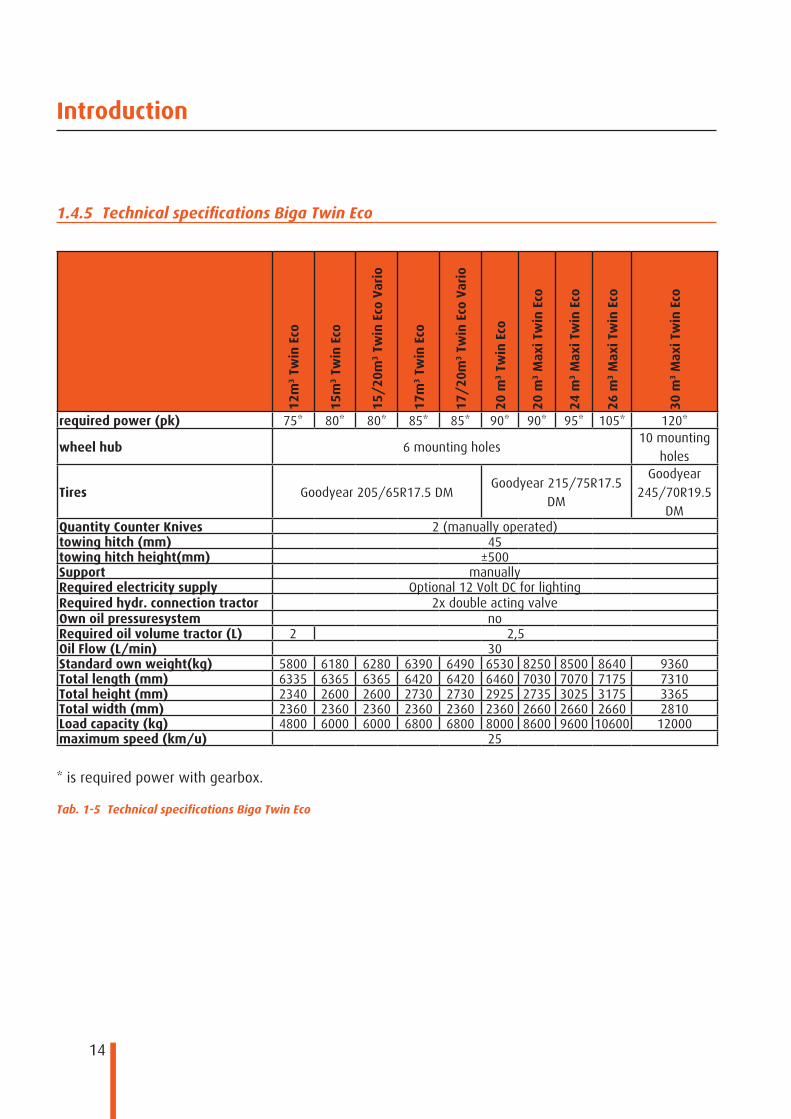
1.4.5 Technical specifications Biga Twin Eco
12m
3 Tw
in E
co
15m
3 Tw
in E
co
15/
20m
3 Tw
in E
co V
ario
17m
3 Tw
in E
co
17/
20m
3 Tw
in E
co V
ario
20 m
3 Tw
in E
co
20 m
3 M
axi T
win
Eco
24 m
3 M
axi T
win
Eco
26 m
3 M
axi T
win
Eco
30 m
3 M
axi T
win
Eco
required power (pk) 75* 80* 80* 85* 85* 90* 90* 95* 105* 120*
wheel hub 6 mounting holes10 mounting
holes
Tires Goodyear 205/65R17.5 DMGoodyear 215/75R17.5
DM
Goodyear 245/70R19.5
DMQuantity Counter Knives 2 (manually operated)towing hitch (mm) 45towing hitch height(mm) ±500Support manuallyRequired electricity supply Optional 12 Volt DC for lightingRequired hydr. connection tractor 2x double acting valveOwn oil pressuresystem noRequired oil volume tractor (L) 2 2,5Oil Flow (L/min) 30Standard own weight(kg) 5800 6180 6280 6390 6490 6530 8250 8500 8640 9360Total length (mm) 6335 6365 6365 6420 6420 6460 7030 7070 7175 7310Total height (mm) 2340 2600 2600 2730 2730 2925 2735 3025 3175 3365Total width (mm) 2360 2360 2360 2360 2360 2360 2660 2660 2660 2810Load capacity (kg) 4800 6000 6000 6800 6800 8000 8600 9600 10600 12000maximum speed (km/u) 25
Tab. 1-5 Technical specifications Biga Twin Eco
* is required power with gearbox.

15
Introduction
1.4.6 Available options Biga Twin Eco
Tab. 1-6 Available options Biga Twin Eco
12m
3 Tw
in E
co
15m
3 Tw
in E
co
15/
20m
3 Tw
in E
co V
ario
17m
3 Tw
in E
co
17/
20m
3 Tw
in E
co V
ario
20 m
3 Tw
in E
co
20 m
3 M
axi T
win
Eco
24 m
3 M
axi T
win
Eco
26 m
3 M
axi T
win
Eco
o
30 m
3 M
axi T
win
Eco
Electr. Weighing system Profifeed ○ ○ ○ ○ ○ ○ ○ ○ ○ ○Electr. Weighing system Digi-star EZ3400V ○ ○ ○ ○ ○ ○ ○ ○ ○ ○Electr. Weighing system + software + Datastick ○ ○ ○ ○ ○ ○ ○ ○ ○ ○Extra Weighing display ○ ○ ○ ○ ○ ○ ○ ○ ○ ○Electrohydr. operation of 2 unloading doors ○ ○ ○ ○ ○ ○ ○ ○ ○ ○Ring to prevent boiling over ○ ○ ○ ○ ○ ○ ● ○ ○ ○Potato cutting knife ○ ○ ○ ○ ○ ○ ○ ○ ○ ○Alligator double life auger i.s.o. double action ○ ○ ○ ○ ○ ○ ○ ○ ○ ○Walterscheid wide angle PTO shaft ○ ○ ○ ○ ○ ○ ○ ○ ○ ○Hand brake axle ○ ○ ○ ○ ○ ○ ○ ○ ○ ○Hydraulically braked axle ○ ○ ○ ○ ○ ○ ○ ○ ○ ○Air braked axle ○ ○ ○ ○ ○ ○ ○ ○ ○ ○2 speed reduction gear box. (540tpm) ○ ○ ○ ○ ○ ○ x x x x2 speed reduction gear box. (1000 tpm) ○ ○ ○ ○ ○ ○ ● ● ● ●Powershift 2 gears ○ ○ ○ ○ ○ ○ ○ ○ ○ ○Ball towing eye Scharmüller / Sauerman 80 mm ○ ○ ○ ○ ○ ○ ○ ○ ○ ○High hitch with DIN towing bracket ○ ○ ○ ○ ○ ○ ○ ○ ○ ○Low pick-up hitch towin bracket and skid food ○ ○ ○ ○ ○ ○ ○ ○ ○ ○Mount. battery for weighing in disconnected position. ○ ○ ○ ○ ○ ○ ○ ○ ○ ○Single acting hydraulic support with manual pump ○ ○ ○ ○ ○ ○ ○ ○ ○ ○Hydraulic support for loading in uncoupled pos. ○ ○ ○ ○ ○ ○ ○ ○ ○ ○Anniversary set ○ ○ ○ ○ ○ ○ ○ ○ ○ ○In height adjustable belt conveyor ○ ○ ○ ○ ○ ○ ○ ○ ○ ○Speed regulator for belt conveyor ○ ○ ○ ○ ○ ○ ○ ○ ○ ○Extra unloading doors placed slantingly at the back ○ ○ ○ ○ ○ ○ ○ ○ ○ ○movable output chutes connected with unloading door ○ ○ ○ ○ ○ ○ ○ ○ ○ ○Perforatd platform with stairs in front of the tub ○ ● ● ● ● ● ● ● ● ●Hydraulic mechanically adjustable counter knives ○ ○ ○ ○ ○ ○ ○ ○ ○ ○Lowering tub height ○ ○ ○ ○ ○ ○ ○ ○ ○ ○Lighting LED ○ ○ ○ ○ ○ ○ ○ ○ ○ ○Extend chassis (for build-up crane or stationary motor) ○ ○ ○ ○ ○ ○ ○ ○ ○ ○Mineral box ○ ○ ○ ○ ○ ○ ○ ○ ○ ○Other RAL-color i.s.o. Peecon red ○ ○ ○ ○ ○ ○ ○ ○ ○ ○Prepared for future mounting of Multilift-system ○ ○ ○ ○ ○ ○ ○ ○ ○ ○
○ = optional● = standardx = not optional
16
Introduction
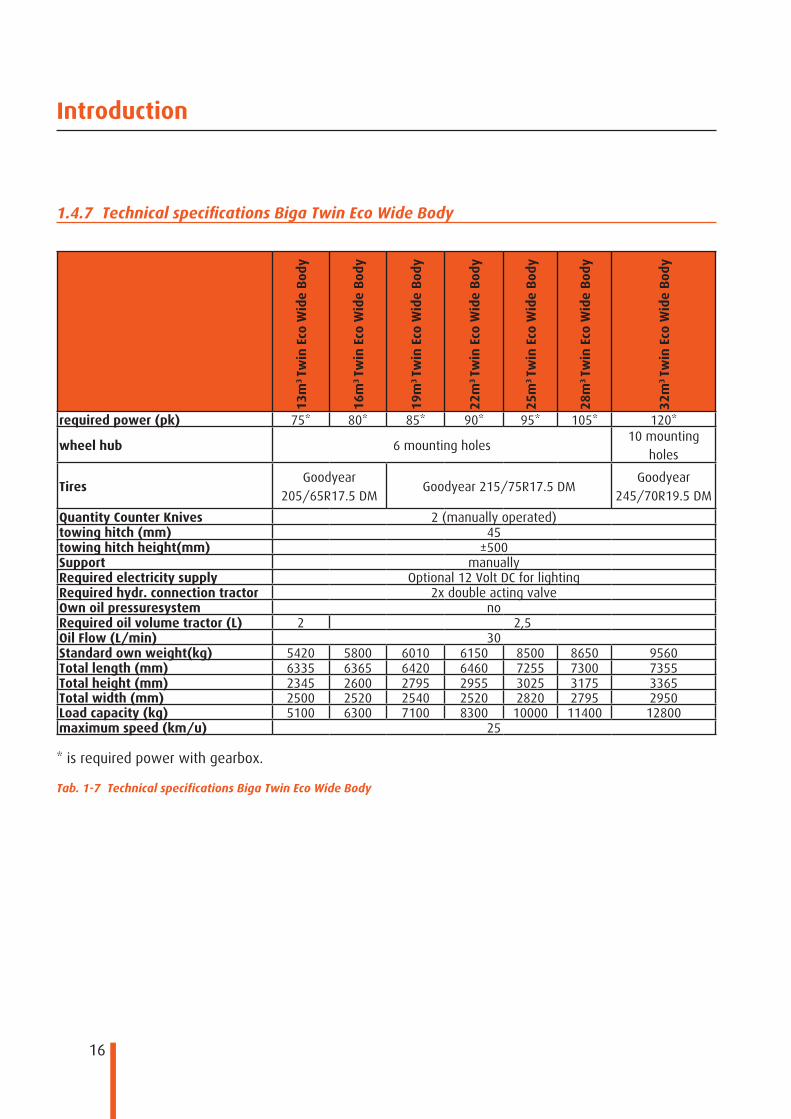
1.4.7 Technical specifications Biga Twin Eco Wide Body
13m
3 Tw
in E
co W
ide
Bod
y
16m
3 Tw
in E
co W
ide
Bod
y
19m
3 Tw
in E
co W
ide
Bod
y
22m
3 Tw
in E
co W
ide
Bod
y
25m
3 Tw
in E
co W
ide
Bod
y
28m
3 Tw
in E
co W
ide
Bod
y
32m
3 Tw
in E
co W
ide
Bod
y
required power (pk) 75* 80* 85* 90* 95* 105* 120*
wheel hub 6 mounting holes10 mounting
holes
TiresGoodyear
205/65R17.5 DMGoodyear 215/75R17.5 DM
Goodyear 245/70R19.5 DM
Quantity Counter Knives 2 (manually operated)towing hitch (mm) 45towing hitch height(mm) ±500Support manuallyRequired electricity supply Optional 12 Volt DC for lightingRequired hydr. connection tractor 2x double acting valveOwn oil pressuresystem noRequired oil volume tractor (L) 2 2,5Oil Flow (L/min) 30Standard own weight(kg) 5420 5800 6010 6150 8500 8650 9560Total length (mm) 6335 6365 6420 6460 7255 7300 7355Total height (mm) 2345 2600 2795 2955 3025 3175 3365Total width (mm) 2500 2520 2540 2520 2820 2795 2950Load capacity (kg) 5100 6300 7100 8300 10000 11400 12800maximum speed (km/u) 25
Tab. 1-7 Technical specifications Biga Twin Eco Wide Body
* is required power with gearbox.

17
Introduction
○ = optional● = standardx = not optional
1.4.8 Available options Biga Twin Eco Wide Body
Tab. 1-8 Available options Biga Twin Eco Wide Body
13m
3 Tw
in E
co W
ide
Bod
y
16m
3 Tw
in E
co W
ide
Bod
y
19m
3 Tw
in E
co W
ide
Bod
y
22m
3 Tw
in E
co W
ide
Bod
y
25m
3 Tw
in E
co W
ide
Bod
y
28m
3 Tw
in E
co W
ide
Bod
y
32m
3 Tw
in E
co W
ide
Bod
y
Electr. Weighing system Profifeed ○ ○ ○ ○ ○ ○ ○Electr. Weighing system Digi-star EZ3400V ○ ○ ○ ○ ○ ○ ○Electr. Weighing system + software + Datastick ○ ○ ○ ○ ○ ○ ○Extra Weighing display ○ ○ ○ ○ ○ ○ ○Electrohydr. operation of 2 unloading doors ○ ○ ○ ○ ○ ○ ○Ring to prevent boiling over ○ ○ ○ ○ ○ ○ ○Potato cutting knife ○ ○ ○ ○ ○ ○ ○Alligator double life auger i.s.o. double action ○ ○ ○ ○ ○ ○ ○Walterscheid wide angle PTO shaft ○ ○ ○ ○ ○ ○ ○Hand brake axle ○ ○ ○ ○ ○ ○ ○Hydraulically braked axle ○ ○ ○ ○ ○ ○ ○Air braked axle ○ ○ ○ ○ ○ ○ ○2 speed reduction gear box. (540tpm) ○ ○ ○ ○ x x x2 speed reduction gear box. (1000 tpm) ○ ○ ○ ○ ● ● ●Powershift 2 gears ○ ○ ○ ○ ○ ○ ○Ball towing eye Scharmüller / Sauerman 80 mm ○ ○ ○ ○ ○ ○ ○High hitch with DIN towing bracket ○ ○ ○ ○ ○ ○ ○Low pick-up hitch towin bracket and skid food ○ ○ ○ ○ ○ ○ ○Mount. battery for weighing in disconnected position. ○ ○ ○ ○ ○ ○ ○Single acting hydraulic support with manual pump ○ ○ ○ ○ ○ ○ ○Hydraulic support for loading in uncoupled pos. ○ ○ ○ ○ ○ ○ ○Anniversary set ○ ○ ○ ○ ○ ○ ○In height adjustable belt conveyor ○ ○ ○ ○ ○ ○ ○Speed regulator for belt conveyor ○ ○ ○ ○ ○ ○ ○Extra unloading doors placed slantingly at the back ○ ○ ○ ○ ○ ○ ○movable output chutes connected with unloading door ○ ○ ○ ○ ○ ○ ○Perforatd platform with stairs in front of the tub ○ ● ● ● ● ● ●Hydraulic mechanically adjustable counter knives ○ ○ ○ ○ ○ ○ ○Lowering tub height ○ ○ ○ ○ ○ ○ ○Lighting LED ○ ○ ○ ○ ○ ○ ○Extend chassis (for build-up crane or stationary motor) ○ ○ ○ ○ ○ ○ ○Mineral box ○ ○ ○ ○ ○ ○ ○Other RAL-color i.s.o. Peecon red ○ ○ ○ ○ ○ ○ ○Prepared for future mounting of Multilift-system ○ ○ ○ ○ ○ ○ ○

18
Introduction
1.4.9 Technical specifications Biga Mammoet
22.5
m3 M
amm
oet
25.5
m3 M
amm
oet
30m
3 M
amm
oet
33m
3 M
amm
oet
WB
36m
3 M
amm
oet
38m
3 M
amm
oet
WB
40m
3 M
amm
oet
42.5
m3 M
amm
oet
WB
45m
3 M
amm
oet
48m
3 M
amm
oet
WB
52m
3 M
amm
oet
required power (pk) 120 125 140 140 150 155 165 170 180 185 200wheel hub 6 mounting holes 10 mounting holes
Tires Goodyear 205/65R17.5 DMGoodyear
245/70R19.5 DM
Goodyear 275/70R22.5 DM
Quantity Counter Knives 2 (manually operated)towing hitch (mm) 45towing hitch height(mm) ±500Support manuallyRequired electricity supply Optional 12 Volt DC for lightingRequired hydr. connection tractor 4x double acting valveOwn oil pressuresystem noRequired oil volume tractor (L) 4 5Oil Flow (L/min) 30Standard own weight(kg) 8300 8600 8765 8860 13000 13050 13800 13805 15600 15650 18000Total length (mm) 8400 8435 8480 8635 9485 9635 9590 9740 10155 10305 12025Total height (mm) 2660 2790 2950 2950 3115 3115 3485 3485 3485 3485 3485Total width (mm) 2360 2360 2360 2520 2660 2800 2660 2800 2810 2900 2660Load capacity (kg) 9000 10200 12000 13200 14400 15200 16000 17000 18000 19200 22000maximum speed (km/u) 25
Tab. 1-9 Technical specifications Biga Mammoet

19
Introduction
○ = optional● = standard
1.4.10 Available options Biga Mammoet
Tab. 1-10 Available options Biga Mammoet
22.5
m3 M
amm
oet
25.5
m3 M
amm
oet
30m
3 M
amm
oet
33m
3 M
amm
oet
WB
36m
3 M
amm
oet
38m
3 M
amm
oet
WB
40m
3 M
amm
oet
42.5
m3 M
amm
oet
WB
45m
3 M
amm
oet
48m
3 M
amm
oet
WB
52m
3 M
amm
oet
Electr. Weighing system Profifeed ○ ○ ○ ○ ○ ○ ○ ○ ○ ○ ○Electr. Weighing system Digi-star EZ3400V ○ ○ ○ ○ ○ ○ ○ ○ ○ ○ ○Electr. Weighing system + software + Datastick ○ ○ ○ ○ ○ ○ ○ ○ ○ ○ ○Extra Weighing display ○ ○ ○ ○ ○ ○ ○ ○ ○ ○ ○Electrohydr. operation of 4 unloading doors ○ ○ ○ ○ ○ ○ ○ ○ ○ ○ ○Ring to prevent boiling over ○ ○ ○ ○ ○ ○ ○ ○ ○ ○ ○Potato cutting knife ○ ○ ○ ○ ○ ○ ○ ○ ○ ○ ○Alligator double life auger i.s.o. double action ○ ○ ○ ○ ○ ○ ○ ○ ○ ○ ○Walterscheid wide angle PTO shaft ○ ○ ○ ○ ○ ○ ○ ○ ○ ○ ○Hand brake axle ○ ○ ○ ○ ○ ○ ○ ○ ○ ○ ○Hydraulically braked axle ○ ○ ○ ○ ○ ○ ○ ○ ○ ○ ○Air braked axle ○ ○ ○ ○ ○ ○ ○ ○ ○ ○ ○Hydraulically forced steered axle ○ ○ ○ ○ ○ ○ ○ ○ ○ ○ ○Existing tandem with extra hydraulically steered axle ○ ○ ○ ○ ○ ○ ○ ○ ○ ○ ○Spring- mounted tridem with 3 hydr. brake axles ○ ○ ○ ○ ○ ○ ○ ○ ○ ○ ○Oil cooler and filtration system ○ ○ ○ ○ ○ ○ ○ ○ ○ ○ ○Hour counter ○ ○ ○ ○ ○ ○ ○ ○ ○ ○ ○Powershift 2 gears ○ ○ ○ ○ ○ ○ ○ ○ ○ ○ ○Powershift 3 gears ○ ○ ○ ○ ○ ○ ○ ○ ○ ○ ○Operation 2 speed reduction gear box (bowden cable) ○ ○ ○ ○ ○ ○ ○ ○ ○ ○ ○Operation 2 speed reduction gear box (electr. hydr.) ○ ○ ○ ○ ○ ○ ○ ○ ○ ○ ○Single acting hydraulic support with manual pump ○ ○ ○ ○ ○ ○ ○ ○ ○ ○ ○Hydr. Support for loading in uncouples position. ○ ○ ○ ○ ○ ○ ○ ○ ○ ○ ○Anniversary set ○ ○ ○ ○ ○ ○ ○ ○ ○ ○ ○Wear out parts Hardox-Raex ○ ○ ○ ○ ○ ○ ○ ○ ○ ○ ○Extra unloading door ○ ○ ○ ○ ○ ○ ○ ○ ○ ○ ○movable output chutes connected with unloading door ○ ○ ○ ○ ○ ○ ○ ○ ○ ○ ○Hydraulic mechanically adjustable counter knives ○ ○ ○ ○ ○ ○ ○ ○ ○ ○ ○Towing bracket and coupling for braking ○ ○ ○ ○ ○ ○ ○ ○ ○ ○ ○Ball towing eye scharmüller/ Sauerman 80mm ○ ○ ○ ○ ○ ○ ○ ○ ○ ○ ○Lighting Led ○ ○ ○ ○ ○ ○ ○ ○ ○ ○ ○Mount. battery for weighing in disconnected position ○ ○ ○ ○ ○ ○ ○ ○ ○ ○ ○Mineral box ○ ○ ○ ○ ○ ○ ○ ○ ○ ○ ○Other RAL-color i.s.o. Peecon red ○ ○ ○ ○ ○ ○ ○ ○ ○ ○ ○Extra charge American version ○ ○ ○ ○ ○ ○ ○ ○ ○ ○ ○Ouput chute with magnets ○ ○ ○ ○ ○ ○ ○ ○ ○ ○ ○Prepared for future mounting of Multilift-system ○ ○ ○ ○ ○ ○ ○ ○ ○ ○ ○

20
Introduction
1.5 Elementary specifications
The Biga feed mixer is made from hollow cold-rolled steel elements combined with sheet steel parts of various thicknesses. Its construction is thus that the durability and rigidity of the Biga feed mixer are optimised. The feed mixer has a sound and stable construction and is very stable while loading, mixing and unloading feed.
Tub
Platform
Chassis
Auger
Unloading door
Fig. 1-1 Main elements
21
Introduction
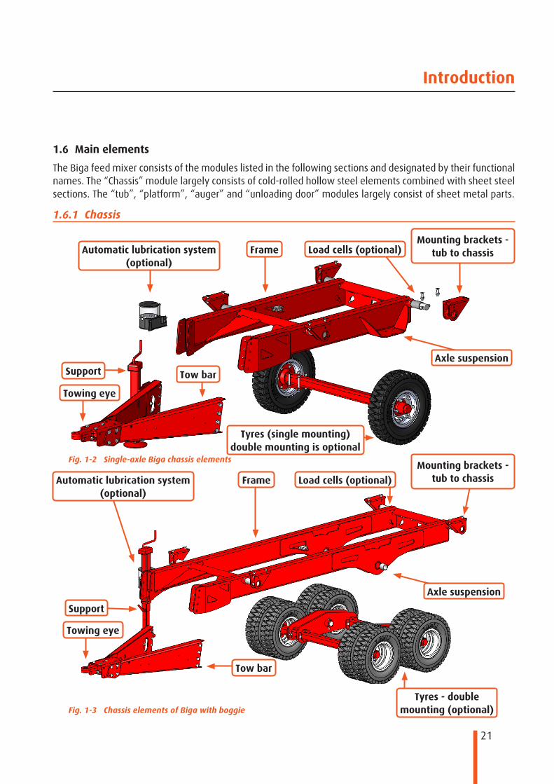
Support
Automatic lubrication system (optional)
Frame
Axle suspension
Tyres (single mounting) double mounting is optional
Tow bar
Towing eye
Load cells (optional)
Fig. 1-2 Single-axle Biga chassis elements
Fig. 1-3 Chassis elements of Biga with boggie
Support
Automatic lubrication system (optional)
Frame
Axle suspension
Tyres - double mounting (optional)
Tow bar
Towing eye
Load cells (optional)
1.6 Main elements
The Biga feed mixer consists of the modules listed in the following sections and designated by their functional names. The “Chassis” module largely consists of cold-rolled hollow steel elements combined with sheet steel sections. The “tub”, “platform”, “auger” and “unloading door” modules largely consist of sheet metal parts.
1.6.1 Chassis
Mounting brackets - tub to chassis
Mounting brackets - tub to chassis

22
Introduction
1.6.2 Tub
Counter knife
Counter knife
Tub
Unloading door
Cylinder point
Hydraulic cylinder
Drive train
Fig. 1-4 Tub elements of multi-auger model
Lubricator
Tub
Unloading doorHydraulic cylinder
Drive train
Fig. 1-5 Tub elements of single auger model
Lubricator

23
Introduction
Auger lifting eye
Large knife
Knife reinforcement
Small knife
Auger
Auger side bearing
NOTE! The auger is a loose component that is pushed over the drive shaft using a special fitted section. Take this into account, e.g. if the feed mixer is turned around for repairs or maintenance.
Fig. 1-6 Auger elements
1.6.3 Auger
The auger element consists of sheet metal parts with hollow pipe sections. The auger is available in various shapes and sizes. The diameter, height and winding have been developed specifically for the individual types of feed mixer. When replacing augers, make sure to install the right auger in your specific feed mixer.
24
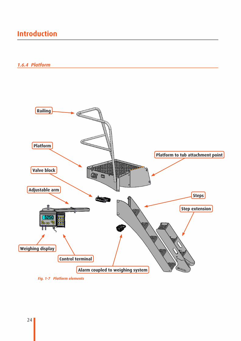
Introduction
Railing
Platform to tub attachment point
Weighing display
Control terminal
Platform
StepsAdjustable arm
Step extension
Alarm coupled to weighing system
Valve block
Fig. 1-7 Platform elements
1.6.4 Platform
25
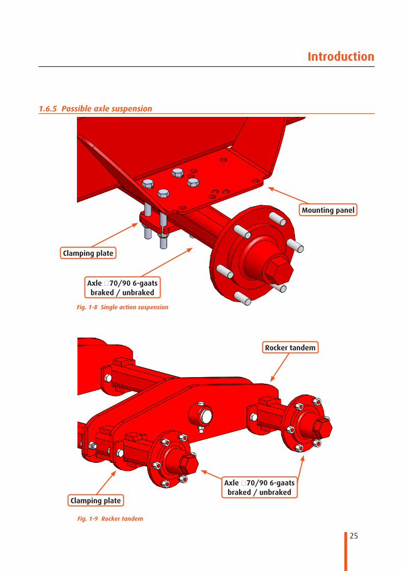
Introduction
Mounting panel
Clamping plate
Axle staag-6 09/07 braked / unbraked
Fig. 1-8 Single action suspension
Fig. 1-9 Rocker tandem
Axle staag-6 09/07 braked / unbraked
Rocker tandem
Clamping plate
1.6.5 Possible axle suspension

26
Introduction
Transport position and parking position
Transport position and parking position
When coupling and uncoupling
When coupling and uncoupling
Version Specifications Content Capacity at 100 bar Capacity at 150 barMax. operating
pressureManual 80x80 S500 - - - -
Hydraulic 100x100 S500 2.8 L 2,800 kg 4,200 kg 200 bar
NOTE! Make sure that after uncoupling the machine, the support has been retracted completely or as far as possible, lowering the tow bar as closely to the ground as possible. This prevents the tow bar from sinking lower if there is a leak in the support or if the soil is not firm enough, as this might otherwise lead to a dangerous situation!
Fig. 1-10 Manually operated support Fig. 1-11 Hydraulically operated support
Tab. 1-11 Support specifications
1.6.6 Support
The entire Biga line has a manually operated support. All these machines also have the option of a hydraulic support. The hydraulic support can be connected in two ways, i.e. through the tractor hydraulics or by means of the hydraulic valve block. If the hydraulic support features a ball valve, this ball valve must be closed whenever the feed mixer is not coupled to a tractor.

27
Introduction
Load cell (optional)
French towing eye
Double Ø 45 mm
DIN74504-40A
Standard Ø 45 mm
Load cell bracket
The weighing system “option” is described in detail in the manual that is part of the delivery and that was specifically drawn up for your feed mixer.
NOTE! Load cells are measuring instruments. Always be aware that these parts are sensitive to shocks and impacts and that they contain electronics.
Fig. 1-12 Weighing system
Fig. 1-13 Towing eye models
1.6.7 Weighing system
Depending on its configuration, the machine may feature:
● a counting/weighing system to determine the volumes loaded. ● a programmable weighing system that enables several feed formulas to be stored. ● a programmable weighing system that enables several feed formulas to be stored and the data to be
transmitted to a PC.
1.6.8 Towing eye
A towing eye serves to enable the trailer to be attached to the tractor. It is also very important that you always check the towing eye for any defects before using the trailer. The Biga models have a standard screw-type towing eye with a Ø45mm eye diameter. Optionally, Peecon delivers a DIN 74504-40A certified towing eye with an eye diameter of Ø40mm or

28
Introduction
Hydraulic cylinder
Hydraulic counter knife
Manually operated counter knife with three positions
Fig. 1-14 Counter knives
1.6.9 Counter knife
The counter knives on your machine are there to shorten the mixing and cutting times. The extended variety has electro-hydraulic operation; in the standard variety this is a manual function. The manually operated version has three fixed settings. The hydraulic version is variable at all the desired settings.

29
Introduction
Guard
Planetary reduction gearbox
Dust cover
Drive shaft
Sliding bearing
Cardan joint
Star bearing
Bearing block
Fig. 1-15 Drive train elements
1.6.10 Drive train with bearing support
The standard drive train of the Biga feed mixer has a guard with a fixed drive train. The power required, as described in section 1.4 “Technical specifications”, can easily be reduced using an optional reduction gear unit (see section 1.6.11). This reduction gear unit reduces the power needed by 20%.
30
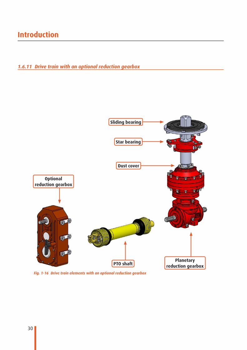
Introduction
PTO shaft
Optional reduction gearbox
Dust cover
Sliding bearing
Star bearing
Planetary reduction gearbox
Fig. 1-16 Drive train elements with an optional reduction gearbox
1.6.11 Drive train with an optional reduction gearbox
31
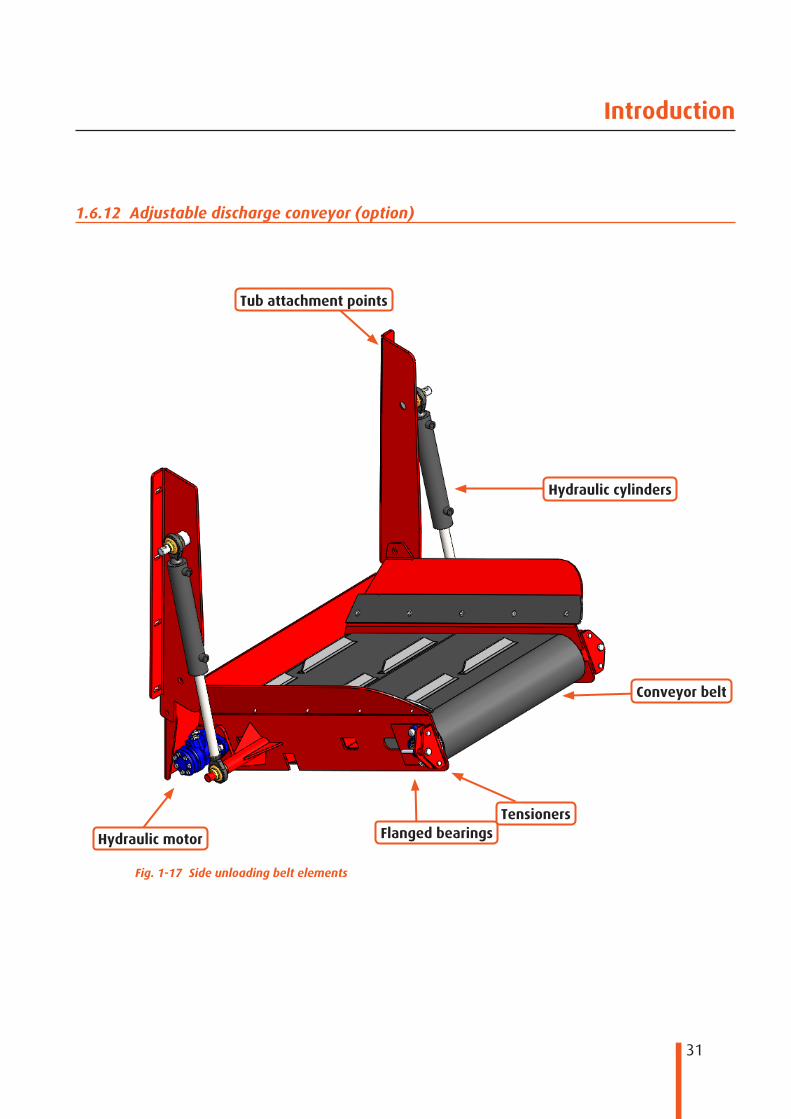
Introduction
Tub attachment points
Tensioners
Hydraulic cylinders
Conveyor belt
Flanged bearingsHydraulic motor
Fig. 1-17 Side unloading belt elements
1.6.12 Adjustable discharge conveyor (option)
32
Introduction
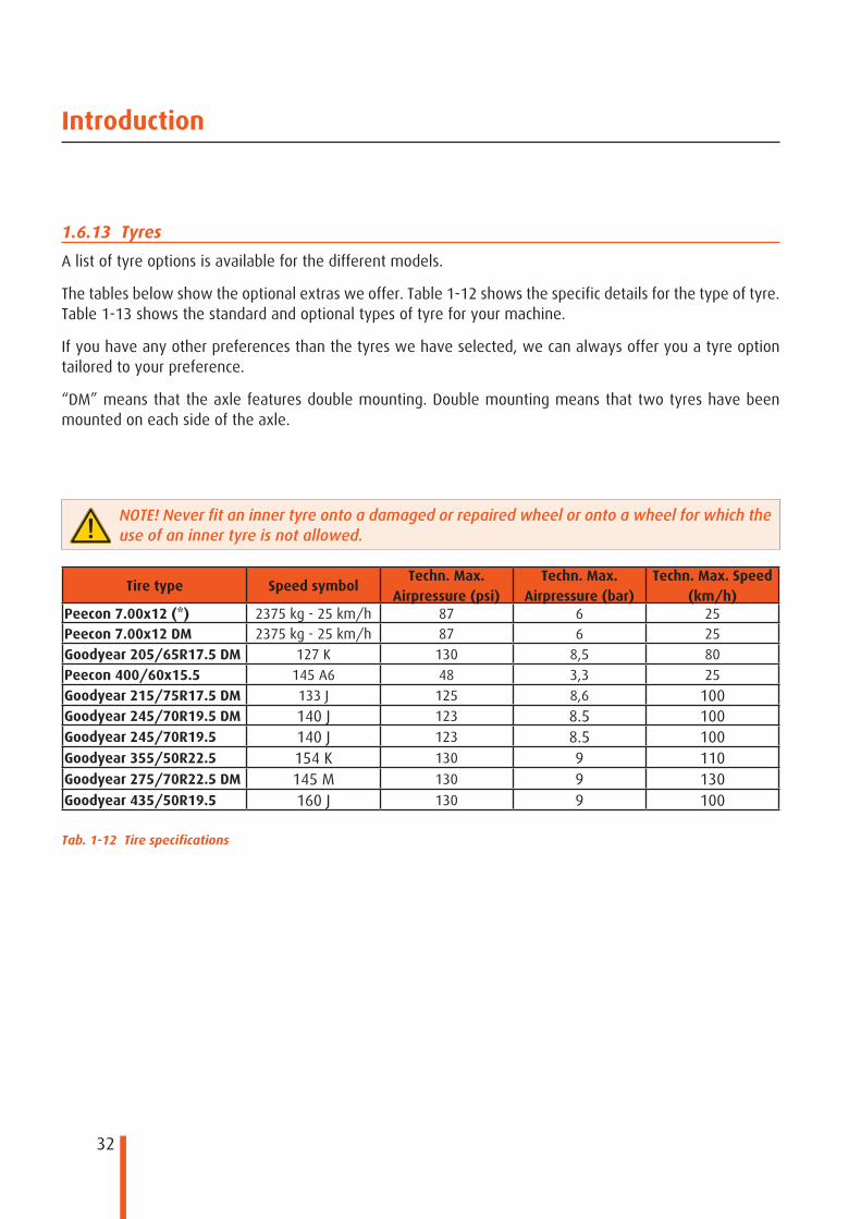
1.6.13 Tyres
A list of tyre options is available for the different models.
The tables below show the optional extras we offer. Table 1-12 shows the specific details for the type of tyre. Table 1-13 shows the standard and optional types of tyre for your machine.
If you have any other preferences than the tyres we have selected, we can always offer you a tyre option tailored to your preference.
“DM” means that the axle features double mounting. Double mounting means that two tyres have been mounted on each side of the axle.
Tire type Speed symbolTechn. Max.
Airpressure (psi)Techn. Max.
Airpressure (bar)Techn. Max. Speed
(km/h)Peecon 7.00x12 (*) 2375 kg - 25 km/h 87 6 25Peecon 7.00x12 DM 2375 kg - 25 km/h 87 6 25
Goodyear 205/65R17.5 DM 127 K 130 8,5 80
Peecon 400/60x15.5 145 A6 48 3,3 25
Goodyear 215/75R17.5 DM 133 J 125 8,6 100Goodyear 245/70R19.5 DM 140 J 123 8.5 100Goodyear 245/70R19.5 140 J 123 8.5 100Goodyear 355/50R22.5 154 K 130 9 110Goodyear 275/70R22.5 DM 145 M 130 9 130Goodyear 435/50R19.5 160 J 130 9 100
NOTE! Never fit an inner tyre onto a damaged or repaired wheel or onto a wheel for which the use of an inner tyre is not allowed.
Tab. 1-12 Tire specifications

33
Introduction
○ = optional, ● = standard, x = not possible.
Pee
con
7.0
0x12
Pee
con
7.0
0x12
D
M*
Goo
dyea
r 20
5/65
R17
.5 D
M
Pee
con
40
0/60
x15.
5
Goo
dyea
r 21
5/75
R17
.5 D
M
Goo
dyea
r 24
5/70
R19
.5 D
M
Goo
dyea
r 24
5/70
R19
.5
Goo
dyea
r 35
5/50
R22
.5
Goo
dyea
r 27
5/70
R22
.5 D
M
Goo
dyea
r 43
5/50
R19
.5
Biga 6m3 Eco ● ○ ○ ○ ○ x x x x xBiga 7.5m3 Eco ● ○ ○ ○ ○ x x x x xBiga 10m3 Eco ● ○ ○ ○ ○ x x x x xBiga 10m3 Maxi Eco ○ ● ○ ○ ○ x x x x xBiga 12m3 Maxi Eco ○ ● ○ ○ ○ x x x x xBiga 12/14m3 Maxi Eco Vario ○ ● ○ ○ ○ x x x x xBiga 13m3 Maxi Eco ○ ● ○ ○ ○ x x x x xBiga 14m3 Maxi Eco ○ ● ○ ○ ○ x x x x xBiga 15m3 Maxi Eco ○ ● ○ ○ ○ x x x x xBiga 6m3 Eco Low ● ○ ○ ○ ○ x x x x xBiga 7.5m3 Eco Low ● ○ ○ ○ ○ x x x x xBiga 10m3 Eco Low ● ○ ○ ○ ○ x x x x xBiga 10m3 Maxi Eco Low ○ ● ○ ○ ○ x x x x xBiga 12m3 Maxi Eco Low ○ ● ○ ○ ○ x x x x xBiga 13m3 Maxi Eco Low ○ ● ○ ○ ○ x x x x xBiga 14m3 Maxi Eco Low ○ ● ○ ○ ○ x x x x xBiga 15m3 Maxi Eco Low ○ ○ ● ○ ○ x x x x xBiga 12m3 Twin Eco ○ ○ ● ○ ○ ○ ○ ○ ○ ○Biga 15m3 Twin Eco ○ ○ ● ○ ○ ○ ○ ○ ○ ○Biga 15/20m3 Twin Eco Vario x ○ ● x ○ ○ ○ ○ ○ ○Biga 17m3 Twin Eco x ○ ● x ○ ○ ○ ○ ○ ○Biga 17/20m3 Twin Eco Vario x ○ ● x ○ ○ ○ ○ ○ ○Biga 20m3 Twin Eco x ○ ○ x ● ○ ○ ○ ○ ○Biga 20m3 Maxi Twin Eco x ○ ○ x ● ○ ○ ○ ○ ○Biga 24m3 Maxi Twin Eco x ○ ○ x ● ○ ○ ○ ○ ○Biga 26m3 Maxi Twin Eco x x ○ x ● ○ ○ ○ ○ ○Biga 30m3 Maxi Twin Eco x x ○ x ○ ● ○ ○ ○ ○Biga 13m3 Twin Eco Wide body x ○ ● x ○ ○ ○ ○ ○ ○Biga 16m3 Twin Eco Wide body x ○ ● x ○ ○ ○ ○ ○ ○Biga 19m3 Twin Eco Wide body x ○ ○ x ● ○ ○ ○ ○ ○Biga 22m3 Twin Eco Wide body x ○ ○ x ● ○ ○ ○ ○ ○Biga 25m3 Twin Eco Wide body x ○ ○ x ● ○ ○ ○ ○ ○Biga 28m3 Twin Eco Wide body x x ○ x ● ○ ○ ○ ○ ○Biga 32m3 Twin Eco Wide body x x ○ x ○ ● ○ ○ ○ ○Biga 22,5m3 Mammoet x x ● x x ○ x x ○ ○Biga 25,5m3 Mammoet x x ● x x ○ x x ○ ○Biga 30m3 Mammoet x x ● x x ○ x x ○ ○Biga 33m3 Mammoet WB x x ● x x ○ x x ○ ○Biga 36m3 Mammoet x x ○ x x ● x x ○ ○Biga 38m3 Mammoet WB x x ○ x x ● x x ○ ○Biga 40m3 Mammoet x x ○ x x ○ x x ● ○Biga 42,5m3 Mammoet WB x x ○ x x ○ x x ● ○Biga 45m3 Mammoet x x ○ x x ○ x x ● ○Biga 48m3 Mammoet WB x x ○ x x ○ x x ● ○Biga 52m3 Mammoet x x ○ x x ○ x x ● ○Tab. 1-13 Tires

34
12 vdc
Introduction
Fig. 1-18 Bowden cable operation
1.6.14 Bowden cable control for reduction gear unit (option)
Tractors whose power is insufficient and that have an optional reduction gear unit can be delivered with a 'Bowden cable'. This is mounted directly onto the gearbox of the machine. The reduction gear unit must be connected to the PTO shaft of the tractor. The speed sticker on the machine indicates the required tractor speed (540 / 1000 rpm). The reduction gear unit consists of a switching gearbox with a 1:1 speed ratio and an extra speed reduction. This extra speed reduction lowers the power required. Always switch on the mixing auger to run the mixing process in low speed reduction mode when the PTO shaft is idle. If possible, switch the gearbox to its 1:1 speed ratio when dispensing silage. This Bowden cable is installed in the cab.
NOTE! If a failure occurs, always contact the dealer.
Fig. 1-19 Electric/hydraulic control panel
1.6.15 Electric control terminal
The Biga line features an optional electric control terminal to enable the hydraulic functions to be operated. The various individual control functions of the Biga are explained in more detail in the following chapters. The control terminal can have a maximum of 12 functions (6 switches) to operate the machine. The switches have been provided with stickers indicating the functions of the individual switches. The hydraulic diagram of the Biga feed mixer has been incorporated into this manual. It is possible that not all functions apply to your machine. The terminal can have various function configurations. This depends on the configuration of your machine. The example shown here is the panel of the standard Biga.
Function 1 is the upper position of the switch. This position usually signifies the “up“, “open“ or “on” functions. Function 2 is the lower position of the switch. Its function is usually “down“, “closed“ or “off“.

35
Introduction
Version Icon 1 Function 1 Icon 2 Function 2
Rotating beacon On Off
Work lamp On Off
Counter knife Extend Retract
Unloading door Open Closed
Side unloading belt Up Down
Unloading belt Left Right
Support Up Down
Bucket Up Down
Multilift Up Down
Silage cutter Up Down
Multilift Tipping position Return
Tab. 1-14 Electric control symbols
1.6.16 Meanings of symbols on the electric control terminal

36
Introduction
Symbol Meaning
DANGER
WARNING AGAINST DANGER / FATAL HAZARD
You may be seriously injured if you do not carry out the procedures carefully.
Fatal hazard: there is a direct risk of your getting killed.
CAREFUL
CAREFUL
The machine may be damaged if you do not carry out the procedures carefully.
NOTE
NOTE
A remark with additional information; alerts you to possible problems.
TIP
TIP
Offers suggestions and advice to help you carry out certain work more easily or more handily.
NOTE! Where “left”, “right”, “front” and “rear” are used in this text, they should be considered as when viewed from the tractor's driving direction.
If you encounter any further questions or problems that this operator's manual does not answer, please contact your dealer or Peeters Landbouwmachines B.V.
Tab. 1-15 Marking conventions
1.7 Marking conventions
This chapter explains the marking conventions used in this operator's manual and their meanings to enable us to draw your attention to certain issues.

37
1
2
3 8
4 9
5 10
6 11
7 12
Introduction
1.8 Main label of your machine
The Peecon brand name covers various types of agricultural machines. For reasons of clarity and transparency, Peeters Landbouwmachines has designed one model of machine identification plate. You can find the specific type of your machine on the machine identification plate on the right-hand side of your chassis.The most recent machine identification plate with a table with the relevant information is shown below.
Fig. 1-20 Peecon machine identification plate
Item Tyre type
1 Manufacturer's contact details2 Series number (identification number)3 Year of manufacture of the machine4 Machine version5 Reserved for extra details (e.g. homologation number)6 Reserved for extra details7 Reserved for extra details8 The maximum total weight of the machine9 The maximum axle load on the 1st axle10 The maximum axle load on the 2nd axle (if present)11 The maximum axle load on the 3rd axle (if present)12 The statutory maximum load on the towing eye (may differ from country to country)Tab. 1-16 Main label

38
Introduction
1.9 Markings on hydraulic hoses
To provide optimum transparency, the hydraulic hoses to the tractor have colour markings. Every colour has its own function. You will find the different colours and functions in the table below.
1.10 Liability and guarantee
To rule out any misunderstandings, we ask you to please read the entire operator's manual with due care and attention. We have tried to guarantee the machine's functionality and your safety. For this reason, we would like to introduce you to a number of things that are not allowed within the lifecycle/warranty period. If you ignore these instructions and warnings, this will be at your own risk and it will invalidate any guarantee provisions and annul our liability.
● The intended usage stated in this operator's manual must not be deviated from in any way without the manufacturer's permission in writing or otherwise the product liability and warranty will no longer apply.
● Original Peecon accessories may be installed later, provided that this is done by the manufacturer or by the dealer in accordance with the manufacturer's assembly and inspection instructions.
● No changes to the machine as a result of your own initiative are allowed, or otherwise all product liability and responsibility on the part of the manufacturer will be terminated. Any damage or loss resulting from the above, including any third party damage or loss, can never qualify for compensation under the warranty.
● Before the product left the factory, great efforts were made to safeguard you against any and all defects in materials and workmanship. Should such defects still occur, Peeters Landbouwmachines B.V. will make all parts that display defects during normal use available for free for a period of twelve months upon delivery (except wear parts). This warranty will lapse if the usage and safety instructions stated in this operator's manual have not been complied with in full or at all.
Colour Function
1x Green Support1x Black Brake1x White Springs2x Red Pressure valve2x Blue Return1x Green/ 1x White Load sensing2x Black Leakage circuit2x Green Hinged door / optionalTab. 1-17 Colour codes
39
Making your machine ready for use
2 Making your machine ready for use2.1 General
When receiving the machine, check it carefully for any transport damage. If the machine is damaged, notify the carrier and the manufacturer of the product immediately.
2.2 Storing the machine
We recommend against storing the machine in cold or moist surroundings for long periods after receiving it and throughout its lifecycle. Make sure that all blank parts are greased and protected properly.
2.3 First time coupling of your feed mixer to your tractor
This section provides a step-by-step explanation of how to couple the Biga feed mixer to the tractor.
1. The tractor’s towing hook should be positioned near the feed mixer’s towing eye, leaving at least a 20-cm clearance. The feed mixer and the tractor must be made safe against unintentionally driving away by applying the hand brake or by placing wheel chocks.
2. If the support is operated manually, retract or extend the support by turning the handle so that the towing eye is positioned slightly higher than the towing hook of the towing vehicle. If the support is operated hydraulically (optional), the hydraulic coupling of the support must be connected to the hydraulic system of the tractor. Open the ball valve and use the tractor valve to retract or extend the support to position the towing eye slightly higher than the tractor’s towing hook.
3. Reverse the tractor and fit the towing pin. Lock the towing pin after connecting it.4. Fully retract the support. If the support is hydraulic, it retracted by opening the tractor valve in question
to remove the oil. On a manual support, you will have to remove the locking pin, fully retract the support, and then replace the locking pin.
5. (option) Connect the 7-pole connector and check the lights.6. Switch off the tractor’s engine and remove the ignition key. Install the PTO shaft between the tractor
and the feed mixer. The tractor side of the PTO shaft is indicated by a sticker on the guard. Check that the maximum speed (rpm) matches the speed (rpm) of the PTO shaft of the tractor. Install the PTO shaft with the shear pin coupling on the machine side. Check the length of the PTO shaft. The outer sleeve must have at least 15 cm space left, allowing it to slide. Shorten the PTO shaft if necessary and carefully deburr the sawn sleeve then. Remove any burrs or chips of metal and grease the sliding surfaces. Consult the manual supplied by the supplier of the PTO shaft for further instructions.

40
Making your machine ready for use
7. Connect the hydraulic system of the feed mixer to the hydraulic system of the tractor. Connect at least one free return hose (hose with a yellow cover) and one single-acting function (hose with a red cover).
NOTE! Make sure that the oil can flow back to your tractor unobstructed so as to prevent pressure building up and faulty hydraulic system operation.
8. If you have a feed mixer with an optional weighing system, plug the power supply lead of the weighing system into the tractor's power supply connection. See the enclosed manual for further details about the weighing system.
9. Carry out the daily maintenance according to the maintenance schedule in Chapter 5.1 before using the machine.

41
Safety instructions
3 Safety instructions
NOTE! Please note that you should read this operator's manual carefully before starting to use the machine. If you encounter any problems, refer to this operator's manual. Make sure that the factory settings have not been changed and check that no parts have come loose during transportation before you start using the machine. Check that all warning signs and labels have been applied in the right places. You must always check the towing eye for defects before using the machine.
3.1 General
The driver or operator is always responsible for any damage or loss and/or accidents resulting from use other than the intended use of this machine or for the safety instructions not being observed. The feed mixer must only be used for mixing, transporting and dispensing livestock feed product. This means that any use for other purposes is not allowed. If the correct lights are not present, you are never allowed to use public roads.
Prior to use, always:
● Carefully check the feed mixer. ● Check that all connecting elements have been installed properly. ● Make sure that the unloading doors have been closed tightly. ● If present, check the brakes and the lights. ● Check that the support has been folded away correctly. ● Make sure that no cargo can blow off or fall from the feed mixer. ● Check that the hand brake is not active and has been retracted completely. ● Check that there are no people within the feed mixer's working range. ● Never exceed the maximum load and driving speed.* ● Study the safety instructions. ● Check the wheel nuts. ● Check the tyre pressure.
*(The maximum allowed even load as indicated on the machine identification plate.)
TIP! If you use the public roads, always comply with the requirements of your national government's body for road traffic, including requirements on maximum axle loads, maximum vehicle dimensions, lights and brakes.

42
Safety instructions
● Due to the risk of exhaust fumes being inhaled, starting, working and test running must never take place in a closed room (art. 69 of the Dutch Decree on Agricultural Safety)
● Check around the machine (and the tractor) before driving off and before putting the machine into use!
● Pay attention to people, animals and particularly to children in the surrounding area. ● Make sure that you can see sufficiently well! ● Stay away from between the machine and the tractor unless the vehicle has been safeguarded against
accidentally rolling away by means of a handbrake and/or wheel chocks having been applied! ● Stay outside the machine's work range and danger zone! ● Always stay outside your machine’s turning radius or clearance circle! ● It is strictly forbidden to be under or in the mixer without using a safety support (available from
Peeters Landbouwmachines B.V.). The kniver on the auger are really sharp. ● Being on the machine while it is in operation or being transported is strictly forbidden! ● Check that the machine has been secured to the tow bar correctly. Specifically make sure that the
towing pin has been locked, e.g. by means of a cotter pin. Carry out the same check for any extra towing point.
● In addition to the specific instructions in this operator's manual, also observe the generally applicable safety and accident prevention instructions!
● Familiarise yourself with all systems and controls and their functions before working with them! If you have to do this while working, it will be too late.
● Always check the working and road safety of the machine and tractor before using them! ● Carefully read the manual for the power take-off shaft befoe working with it! ● Users must only wear tightly fitting clothes! Avoid loose clothing! ● Always match your driving speed to the circumstances of the environment and the terrain! Never take
sudden turns when driving up or down hill and when driving perpendicularly across a slope! ● Machines that are carried or towed, as well as front weights, affect the driving behaviour, steerability
and brake operation! You must therefore ensure sufficient steering and brake operation! ● When going through bends, take into account the increased width (turning circle) and/or the increased
mass (inertia) of the machine! ● The machine must only be operated by one person! ● Make the machine safe before leaving the tractor! Switch off the motor/engine and remove the
ignition key. In the event of electrical operation, always deactivate the switch functions and pull out the plug.
● When working with the power take-off shaft, there must not be anyone within the range of the turning power take-off shaft and clutch shaft!
DANGER! We would like to present some common situations where you should be extra mindful in order to ensure your safety and that of others in your vicinity.
CAREFUL! Points where you have to act with extra caution and observe extra care for yourself and your machine are listed below.

43
Safety instructions
● Couple the machine in keeping with the instructions and make sure that the connection is secured properly!
● Be particularly carefully when coupling and uncoupling the machine or the tractor! ● Only work with machines if their protection is complete and intact and functions properly! ● Immediately repair any wear or damage to the paintwork before working with the machine again!
If the machine is still covered by warranty, always contact your dealer or the manufacturer before making repairs.
● Every now and then, check the hydraulic hoses for damage. Damaged hoses must be replaced immediately by hoses of the prescribed quality (SAE 100 R2A according to DIN 20022/2). Never try to manually seal an oil leak on a running motor/engine. The oil might penetrate your skin and cause blood poisoning!
NOTE! Pay attention to these points when first installing the machine behind a tractor. This prevents hydraulic functions not working at all or working incorrectly.
● Check the direction of rotation and rpm chosen for the power take-off shaft before switching on the power take-off shaft. Change them if they do not match the required direction of rotation and rpm (see stickers)!
● Always switch off the power take-off shaft when it is not in use. ● Machines driven by means of a clutch shaft as well as the actual clutch shaft shall only be cleaned,
lubricated or adjusted after the power take-off shaft has been switched off, the motor/engine has been switched off, and the ignition key has been removed!
● The driver must always be in the driver seat while driving and operating the machine! ● Observe the statutory regulations on transport using public roads. Also pay attention to the lights
required and front, rear and side reflectors! ● Always check that the machine complies with the permissible transport dimensions. ● Switch off the power take-off shaft whenever it is not necessary, as otherwise the oil's viscosity might
worsen unnecessarily. ● Carry out weekly checks to make sure that the knives and screws/bolts on the auger have not worn too
much. A knife may end up in the feed, which may lead to a dangerous / animal unfriendly situation.
44
5 meter
5 meter
10 meter10 meter
Safety instructions
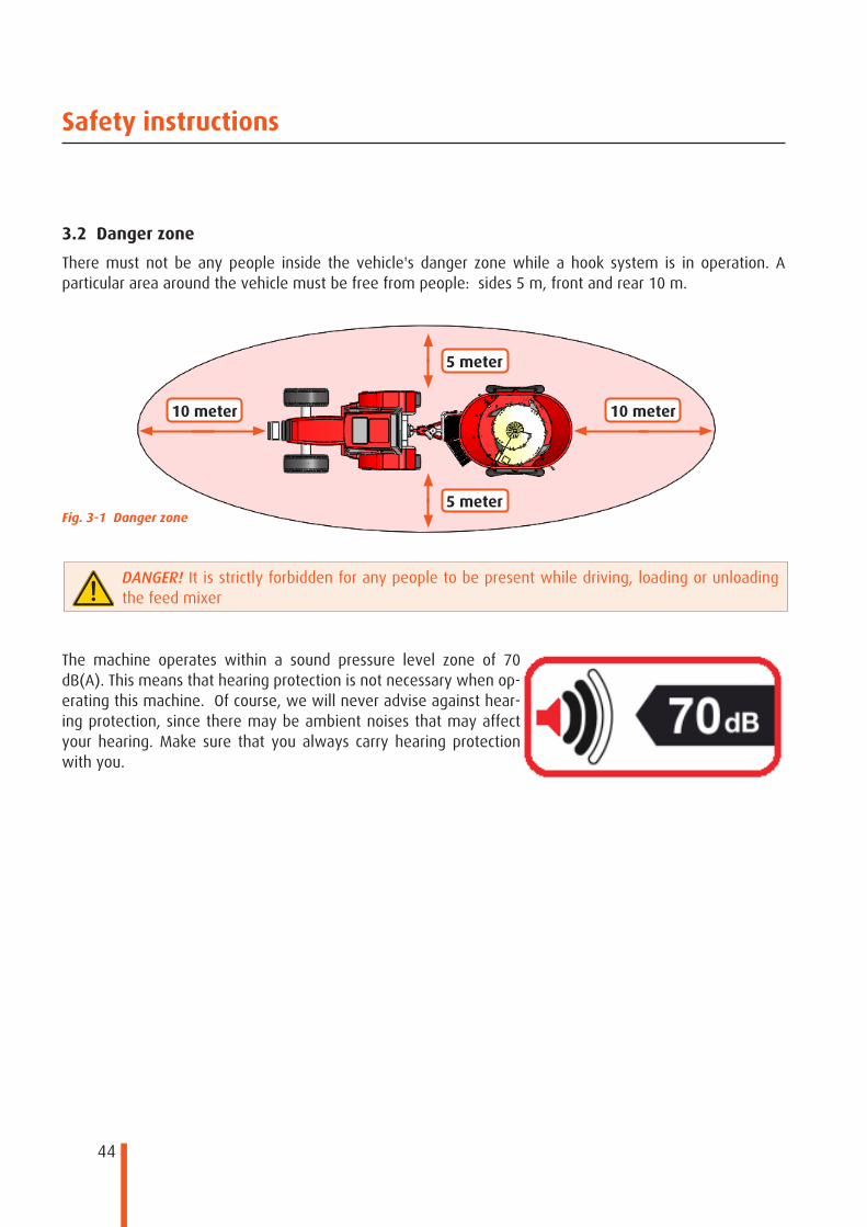
3.2 Danger zone
There must not be any people inside the vehicle's danger zone while a hook system is in operation. A particular area around the vehicle must be free from people: sides 5 m, front and rear 10 m.
Fig. 3-1 Danger zone
The machine operates within a sound pressure level zone of 70 dB(A). This means that hearing protection is not necessary when op-erating this machine. Of course, we will never advise against hear-ing protection, since there may be ambient noises that may affect your hearing. Make sure that you always carry hearing protection with you.
DANGER! It is strictly forbidden for any people to be present while driving, loading or unloading the feed mixer

45
Safety instructions
3.3 Coupling and uncoupling the machine
This section describes the safety instructions that are important while coupling and uncoupling the machine.
● Couple the machine to the tractor's tow bar according to the instructions referred to above. ● Only use suitable tractors to work with the machine and to transport the machine. ● Make sure that the following values are never exceeded:
● Maximum permissible axle load ● Maximum permissible tractor towing eye load. ● Maximum permissible total tractor weight.
● Before uncoupling the machine, take precautions to prevent it rolling away.
3.4 Using the machine
● Familiarise yourself with the entire machine and all controls before starting to work with the machine! If you have to do this while working, it will be too late.
● Pay attention to the maximum permitted total weight of the machine, the maximum axle load of the tractor, and the maximum tow point load! If necessary, drive with a partially filled machine.
● Only use the machine if all the safety and protection facilities have been installed as instructed and are closed!
● Wear tightly fitting clothes! Loose clothing increases the risk of it being caught by, and wound around, a turning drive shaft or other shaft!
● The presence of people in the machine's operating and danger zones is strictly forbidden. ● There are also dangerous areas in locations where other forces act upon machine parts (e.g. hydraulic
drives)!
● When coupling or uncoupling the machine, put the support in the relevant position (safety position). ● Be careful while coupling and uncoupling the machine to the tractor! There are highly dangerous areas
(a danger of getting caught and crushed) between the tractor and the machine, near the coupling point.
● Check any connected feed hoses. Make sure that: ● no hoses can chafe against the machine parts. ● any movements required when going through bends can be made without any tensioning or
buckling. ● The uncoupled machine must be secured so that it cannot roll away by making sure that there is
sufficient pressure on the support while uncoupling.
DANGER! Make sure there is no one in the danger zone between the tractor and the machine when driving the tractor towards the machine!
46
Safety instructions
● Such machine parts that are driven by other forces may only be operated if there is nobody within the machine's danger zone!
● Before leaving the tractor, safeguard it against it being started unexpectedly and/or rolling off!
3.5 Safety symbols
For extra safety, your hook system features some safety and warning stickers to remind you of any residual risks that may still occur when using the machine in spite of its safe design. Always read the operator's manual before commissioning the machine. Follow all the instructions in the operator's manual.
Check that all warning indicators are present. If they are not, do not work with the machine but contact the dealer and make sure that the warning indicators are replaced/renewed as necessary.
The stickers consist of an image depicting the danger (with a triangle) and an image indicating how to prevent the danger.
TIP! To enable all (new) users to work safely, the stickers must always be clean and clearly legible; always replace any stickers that are damaged. You can obtain new stickers from your dealer/manufacturer.
3.5.1 Explanation of the safety symbols used
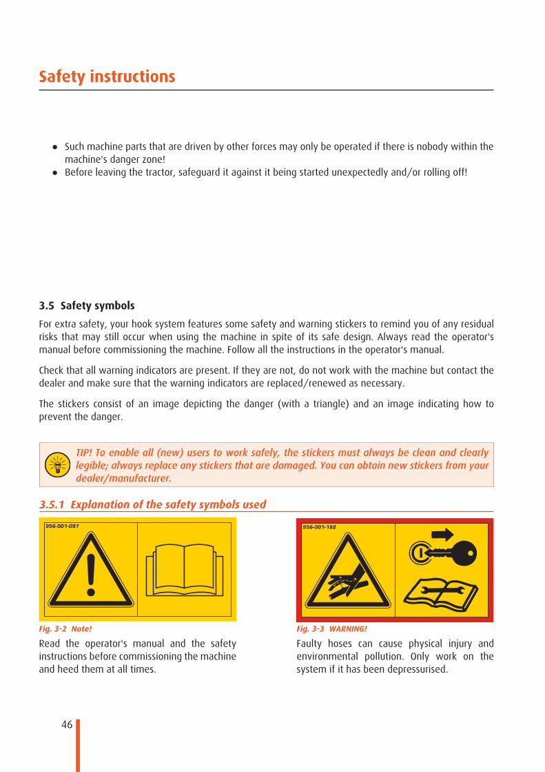
Fig. 3-2 Note!
Read the operator's manual and the safety instructions before commissioning the machine and heed them at all times.
Fig. 3-3 WARNING!
Faulty hoses can cause physical injury and environmental pollution. Only work on the system if it has been depressurised.
47
Safety instructions
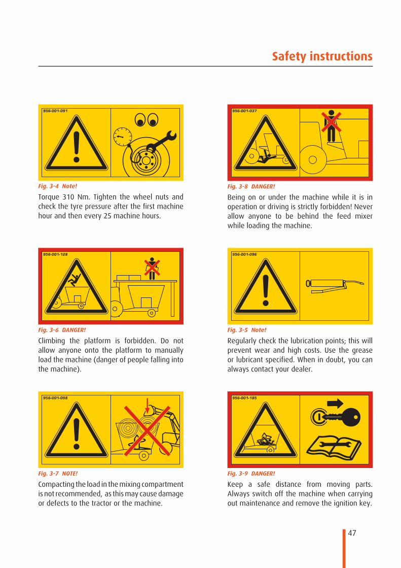
Fig. 3-4 Note!
Torque 310 Nm. Tighten the wheel nuts and check the tyre pressure after the first machine hour and then every 25 machine hours.
Fig. 3-5 Note!
Regularly check the lubrication points; this will prevent wear and high costs. Use the grease or lubricant specified. When in doubt, you can always contact your dealer.
Fig. 3-6 DANGER!
Climbing the platform is forbidden. Do not allow anyone onto the platform to manually load the machine (danger of people falling into the machine).
Fig. 3-7 NOTE!
Compacting the load in the mixing compartment is not recommended, as this may cause damage or defects to the tractor or the machine.
Fig. 3-8 DANGER!
Being on or under the machine while it is in operation or driving is strictly forbidden! Never allow anyone to be behind the feed mixer while loading the machine.
Fig. 3-9 DANGER!
Keep a safe distance from moving parts. Always switch off the machine when carrying out maintenance and remove the ignition key.
48
Safety instructions
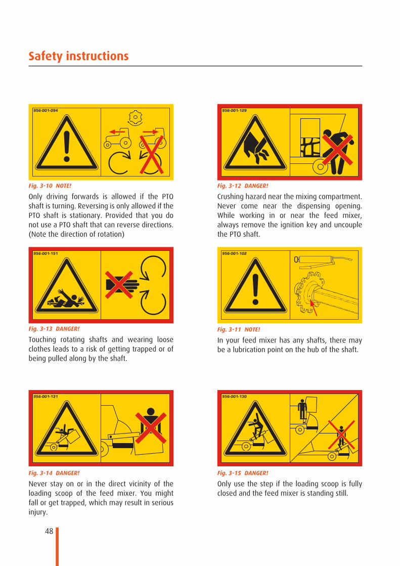
Fig. 3-10 NOTE!
Only driving forwards is allowed if the PTO shaft is turning. Reversing is only allowed if the PTO shaft is stationary. Provided that you do not use a PTO shaft that can reverse directions. (Note the direction of rotation)
Fig. 3-11 NOTE!
In your feed mixer has any shafts, there may be a lubrication point on the hub of the shaft.
Fig. 3-12 DANGER!
Crushing hazard near the mixing compartment. Never come near the dispensing opening. While working in or near the feed mixer, always remove the ignition key and uncouple the PTO shaft.
Fig. 3-13 DANGER!
Touching rotating shafts and wearing loose clothes leads to a risk of getting trapped or of being pulled along by the shaft.
Fig. 3-14 DANGER!
Never stay on or in the direct vicinity of the loading scoop of the feed mixer. You might fall or get trapped, which may result in serious injury.
Fig. 3-15 DANGER!
Only use the step if the loading scoop is fully closed and the feed mixer is standing still.
49
Safety instructions
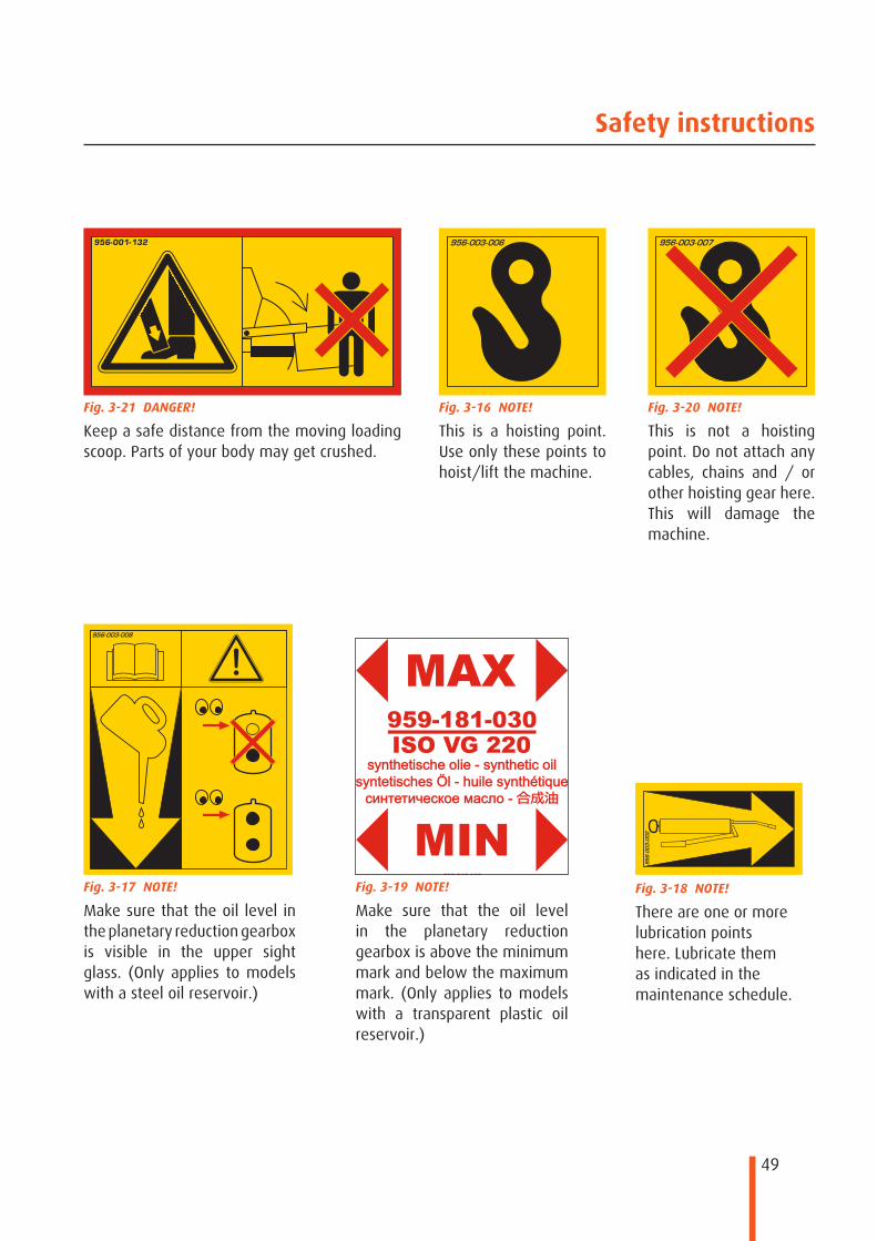
Fig. 3-16 NOTE!
This is a hoisting point. Use only these points to hoist/lift the machine.
Fig. 3-17 NOTE!
Make sure that the oil level in the planetary reduction gearbox is visible in the upper sight glass. (Only applies to models with a steel oil reservoir.)
Fig. 3-18 NOTE!
There are one or more lubrication points here. Lubricate them as indicated in the maintenance schedule.
Fig. 3-19 NOTE!
Make sure that the oil level in the planetary reduction gearbox is above the minimum mark and below the maximum mark. (Only applies to models with a transparent plastic oil reservoir.)
Fig. 3-20 NOTE!
This is not a hoisting point. Do not attach any cables, chains and / or other hoisting gear here. This will damage the machine.
Fig. 3-21 DANGER!
Keep a safe distance from the moving loading scoop. Parts of your body may get crushed.

50
Safety instructions
Fig. 3-22 NOTE!
The position of the loading scoop can be read out on the tow bar from the tractor, using the indicator rod and the above sticker. Position “0” indicates that the scoop has been lowered completely. Multiplying this value by 6 gives the scoop position in degrees. I.e. position 15 means that the scoop is at 90 degrees: closed.
Fig. 3-23 NOTE!
The position of the (front) unloading door(s) can be read out from the side of the tub via the indicator and the above sticker. Position 0 means that the door is closed, position 9 means that the door has been opened to its maximum extent.
Fig. 3-24 NOTE!
The position of the rear unloading door(s) can be read out on the front of the tub by means of the indicator and the above sticker. Position 0 means that the door is closed, position 9 means that the door has been opened to its maximum extent.

51
1
2
1
11
213
4
6
7
8
9
9
11
123 13
4
14
5
6
7
8
9
10
5
Safety instructions
3.5.2 Safety symbols on de machine
Fig. 3-25 Positions of the safety symbols
Fig. 3-26 safety symbols on the Biga Eco series
52
1
11
2
2
12
13 4
5
6
7
8
8
9
9
9
9
1 11 4
6
7
8
9
9
2
5
8
13
Safety instructions
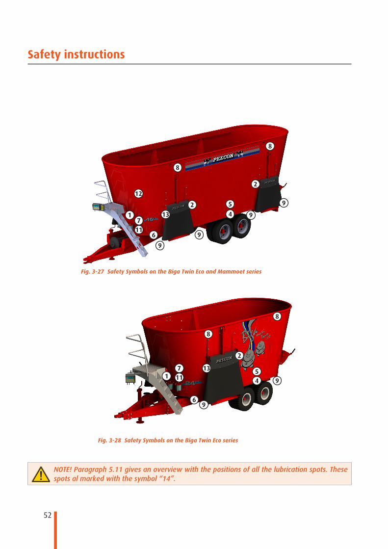
Fig. 3-27 Safety Symbols on the Biga Twin Eco and Mammoet series
Fig. 3-28 Safety Symbols on the Biga Twin Eco series
NOTE! Paragraph 5.11 gives an overview with the positions of all the lubrication spots. These spots al marked with the symbol “14”.

53
1
11
46
7
8
9 9
132
5
Safety instructions
Fig. 3-29 Veiligheidssymbolen
op Biga Eco Low modellen
3.6 Brake systemThe brake system of the tractor must match the brake system of the machine. If the machine does not work prop-erly, stop the towing vehicle immediately and have the fault repaired. Any repairs and adjustments to the brake system must only be carried out by experts and specialists in this field. Have the system checked regularly to prevent unexpected downtime. Grease all the grease nipples every 200 machine hours or once a year; this will extend your machine’s service life.
If you have to carry out any work, such as grinding, welding and/or drilling, in the direct vicinity of the brake system, then make sure that these vital parts have been screened off properly and cannot be damaged.
If you have a hand-braked axle, test it by pulling the brake lever. This should lock the wheels. This system should also be lubricated every 200 machine hours or once a year.
3.7 Extreme situationsThis section lists some extreme situations. Should you ever find yourself in such a situation, then please remember that the system may start to misfunction.
The recommended operating/ambient temperature is between -30°C and +40°C. Using the system at lower tempera-tures will lead to accelerated wear to hydraulic gaskets and it will increase the risk of hydraulic hoses being damaged and brittle fractures in the steel structure. If you work at temperatures lower than the recommended temperature, the maximum load that can be lifted is lower than what is normally allowed.
Before starting to work at a low temperature, have the oil circulate through the system for some minutes. Slowly repeat all actions several times so that the gaskets will become flexible before being exposed to full pressure.
If working in extremely high temperatures, remember that the hydraulic oil will heat up extremely. If the oil tem-perature exceeds +80°C, the oil will evaporate and the gaskets will be damaged

54
Function description
4 Function description4.1 Coupling the machine
Before driving the tractor/machine combination study the safety instructions and warnings. Make sure there are no people in the direct vicinity of the vehicle while operating the tractor or feed mixer. (See the danger zone section 3.2)
DANGER! If you hear any unusual noises, especially loud noises, this might be a sign of unsafe usage. Immediately stop your work and find and remedy the problem.
DANGER! There must not be any people in the direct vicinity of the vehicle while loading the machine (danger zone).
1. Prevent the machine from rolling away. Apply wheel chocks or engage the hand brake.2. When coupling the machine, check it for any visible defects.3. Couple the tow bar.4. Make the hydraulic connections.5. Connect the brake hoses. (optional)6. Connect the PTO shaft.7. Plug the control panel cable into the holder on the tractor. (optional)8. Connect the electrical power supply leads / lighting cable. (optional)9. Place the support in transport position. Refer to chapter 1.6.6 for this.10. Release the feed mixer hand brake. (optional)
You are now ready to drive off with the feed mixer.
4.2 Loading the machine
Heed the following warnings before loading. (Note the danger zone, section 3.2) Section 4.6 describes the recommended loading sequence. Refer to this sequence for the most effective and efficient procedure.

55
Function description
4.3 Mixing the feed.
This section provides an indication of the mixing cycle that can generally be followed. This will vary for the different configurations; set the time and cutting speed based on your own experience.
1. To achieve an optimally homogeneous mixture, leave the machine to mix and cut for another 5 to 8 minutes (depending on the product loaded) while the tub is full. Machines with a wide-angle PTO shaft (optional) also allow for mixing during transportation.
2. The cutting intensity of the knives can be adjusted by repositioning the two counter knives at the front and rear of the machine.
3. The speed of the mixing auger can be controlled by adjusting the speed of the tractor or the reduction gear unit.
1. Place the machine by the product to be loaded. If you wish to have the feed mixer mix while loading, place the tractor in front of the feed mixer, in a straight line.
2. Make sure that the machine has been set up fully horizontally.3. Check that the unloading slide valve has been closed.4. (Optional) Switch on the weighing system, set it to the right feed program if required.5. Switch on PTO shaft at a low speed without throttling down the motor speed while loading.6. Then load the machine from the side, centrally in the centre. Prevent overloading the auger: do not
load too much produce in the feed mixer as a single batch.7. Introduce the loading bucket or the fork into the tub as far as possible in order to minimise the
dropping distance of the product. This prevents the knives and the auger from being damaged. Make sure not to touch the auger with the loading bucket or the fork.
8. Mix the feed as described in section 4.3.
TIP! If you wish to use the feed mixer to process round or square bales, you should split them up instead of loading complete bales. This reduces the mixing time and prevents the auger from being overloaded.
TIP! Before mixing round bales, you should start at a low speed and increase this as the bale is cut up.
TIP! The machine can be fitted with special hay augers to prevent “boiling over” when mixing round bales and hay. The machine can also be fitted with a special ring to prevent “boiling over”.
DANGER! A shear pin protects the augers against overloading. The shear pin is located at the bottom of the feed mixer, where the PTO shaft is mounted to the support bearing. Only use original shear pins!

56
Function description
4.4 Unloading feed
1. Switch on the PTO shaft; this will cause the mixing auger to turn.2. (optional) If a conveyor belt is applied: Engage the conveyor belt.3. Open the unloading slide valve; you can determine the amount of feed to be dispensed by adjusting
the opening distance of this slide valve. The “cow / arrow” indicator indicates how far the unloading slide valve has opened.
4. When the tub is nearly empty, you can remove the last remnants of feed from the auger by increasing the PTO shaft (auger) speed.
5. Lower the tractor engine and auger speeds.6. (option) If a conveyor belt is used: Switch off the conveyor belt.7. Switch off the PTO shaft.8. Close the unloading slide valve.
DANGER! Abruptly stopping the auger at a high speed may damage your reduction gearbox(es). Always lower this speed before switching off the PTO shaft.
4.5 Parking the feed mixer
When driving the machine on public roads, it must have a hydraulic service brake if its empty weight is more 3,500 kg (this can differ when loaded and from country to country). The tractor and the machine must then be fitted with hydraulic brakes. In this case, connect the hydraulic brake clutch to the tractor's hydraulic brake system. When parking the machine, apply the hand brake by turning the hand brake spindle. Do not forget to release the hand brake when coupling the machine to the tractor and check that the brake system and the lights work before going out onto public roads.

57
Function description
4.6 Recommended loading sequence
A guideline for the loading sequence for different components is provided below. However, this is just a general guideline. Another sequence may be preferred for specific products in real-life situations.
1. Always load the longer / lighter structured products (hay) first. Try to load these products into the mixing compartment in a controlled manner, so as to prevent overloading the compartment. First rip round or square bales apart. “If possible” Always load bales between two augers to prevent the bales from rotating along on the auger. When loading several bales, always let the machine process the first bale before adding the next one. You can switch on the counter knives to improve the cutting action. This will not be necessary if you mainly feed maize or grass silage; in that case the counter knives had better not be used, since the use of activated counter knives requires extra power from your tractor.
2. Then load concentrated feed, feed pellets etc.3. Add any minerals.4. Load grass silage5. Load maize and/or cereal silage6. Load products with high moisture content (brewers' grain, beets, orange peels, etc.)7. Load any liquid components (molasses, etc)

58
Maintenance and inspection
5 Maintenance and inspection5.1 General
The best way to make sure that the hook arm system will continue to work proper and to minimise repair is by using it correctly and carefully. The required precautions to prevent accidents must be taken during all maintenance activities. The safety instructions must be complied with and any repairs may only be carried out by trained technicians.
NOTE! The engine/motor of the vehicle must be off during maintenance work and the ignition key must have been removed and taken away by the trained technician. The PTO must be off.
This operator's manual concerns the use of the machine in the state in which it was marketed, excluding any components added and/or modifications implemented by the end user at a later date. Any conversion of the installation not implemented by Peeters Landbouwmachines B.V. or the relevant dealer is not allowed.
If studying the machine reveals that damage will have to be repaired or that a preventative repair will be necessary, the component to be repaired must be replaced by an original component as detailed in the parts list. Any failure to respect this provision will remove any liability as regards such structural change.
While carrying out maintenance, the tipped frame must be made safe by placing a support under the rear tipping frame.

59
Maintenance and inspection
5.2 General inspection
Proper maintenance extends the service life of the hook system. Any defects can then be found at an early stage, so as to prevent any further or consequential damage or loss. Peeters Landbouwmachines B.V. does not accept any responsibility for direct or consequential damage or loss resulting from poor maintenance. Heed the following warnings before carrying out the necessary maintenance activities.
● Only carry out maintenance if the system has been placed in a straight and stable position and the tractor has been uncoupled.
● Never seal any holes or leaks in hydraulic hoses or pipes with your bare/covered fingers and/or hands. Replace the entire circuit.
● If you carry out repairs on a raised installation, always install a support under the tipping frame. (see chapter 5.1)
● Always wear safe clothing and shoes and work in an uncluttered and clean work environment. ● Only use water to clean the machine; do not use any aggressive cleaners.
5.3 Daily inspection
Before starting to work with the hook system, you must always do the following checks: ● Check the entire construction for visible tears and cracks and any deformation. ● Check that the unloading doors work properly. ● Check the operation/controls in combination with the hydraulic valve block for defects. ● Check the hydraulic hoses and circuits for leaks, damage and that they are not obstructed. ● Check the hydraulic cylinders for leaks. ● Check the rubber flaps at the unloading door for any cracks or fissures. ● Check that sufficient oil is available for the hydraulic system. ● (optional) Check that the discharge belt works properly. ● Check that the bolted connections on the auger are still intact and have not worn excessively.
NOTE! Never top up the oil in the oil tank if not all the cylinders have been extended. Changes in its level might otherwise cause the tank to flow over!
If any of the above items is found to not be okay, then contact the dealer or manufacturer before taking action!
5.4 Weekly maintenance items
Do not forget to also carry out the daily inspection in combination with these items! ● Lubricate all lubrication points. ● If present: Drain all liquid from the air brake system through the air tank. ● If present: clean the discharge belt thoroughly to prevent moulds and corrosion.

60
Maintenance and inspection
5.5 Monthly maintenance items
Do not forget to also carry out the weekly inspection in combination with these items! ● Clear the hydraulic valve block of any serious contamination, such as sand. ● If present: Check and clean the oil filter if it is visibly contaminated. ● Make sure that the oil tank's de-aeration valve is free from dirt; clean it if necessary.
5.6 Annual maintenance items
(or after 2,000 container changing cycles, whatever is reached the first) ● Replace the oil filter. ● Replace the oil if necessary. ● If present: Adjust the brakes if necessary.
5.7 After commissioning
● Do not clean the installation using a steam or pressure cleaner for the first six weeks after commissioning the installation, since the paint may still have not hardened to its full strength.
● When cleaning the machine, always make sure not to apply the jets of steam or pressure cleaners to the lubrication points, cylinder seals and steering/control valves at any time during the machine's lifetime. Apply new grease to all lubrication points after cleaning.
● All bolts, nuts and connections must be checked and, if necessary, tightened after about 8 machine hours.
5.8 Decommissioning for more than 1 month
● Thoroughly clean and dry the machine. ● Check all moving parts and the protection of the machine. Replace/Repair them if necessary. ● Check that all bolts and nuts have been tightened correctly. ● When not in use, the machine should preferably be parked in a covered, locked location.
5.9 Torques
A summary of the torques of the various bolts on the feed mixer is provided below.
Tab. 5-1 Torques for 8.8 bolts
Nominal dimensions Spanner width (mm) Torque (Nm)M8 13 27M10 17 57M12 19 101M14 22 148M16 24 230M18 27 348M20 30 464M22 32 634M24 36 798M27 41 1176M30 46 1597M18x1.5 (wheel nut) 27 270M20x1.5 (wheel nut) 30 350M22x1.5 (wheel nut) 32 450
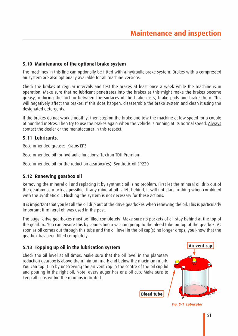
61
Maintenance and inspection
5.10 Maintenance of the optional brake system
The machines in this line can optionally be fitted with a hydraulic brake system. Brakes with a compressed air system are also optionally available for all machine versions.
Check the brakes at regular intervals and test the brakes at least once a week while the machine is in operation. Make sure that no lubricant penetrates into the brakes as this might make the brakes become greasy, reducing the friction between the surfaces of the brake discs, brake pads and brake drum. This will negatively affect the brakes. If this does happen, disassemble the brake system and clean it using the designated detergents.
If the brakes do not work smoothly, then step on the brake and tow the machine at low speed for a couple of hundred metres. Then try to use the brakes again when the vehicle is running at its normal speed. Always contact the dealer or the manufacturer in this respect.
5.11 Lubricants.
Recommended grease: Kratos EP3
Recommended oil for hydraulic functions: Textran TDH Premium
Recommended oil for the reduction gearbox(es): Synthetic oil EP220
5.12 Renewing gearbox oil
Removing the mineral oil and replacing it by synthetic oil is no problem. First let the mineral oil drip out of the gearbox as much as possible. If any mineral oil is left behind, it will not start frothing when combined with the synthetic oil. Flushing the system is not necessary for these actions.
It is important that you let all the oil drip out of the drive gearboxes when renewing the oil. This is particularly important if mineral oil was used in the past.
The auger drive gearboxes must be filled completely! Make sure no pockets of air stay behind at the top of the gearbox. You can ensure this by connecting a vacuum pump to the bleed tube on top of the gearbox. As soon as oil comes out through this tube and the oil level in the oil cup(s) no longer drops, you know that the gearbox has been filled completely.
5.13 Topping up oil in the lubrication system
Check the oil level at all times. Make sure that the oil level in the planetary reduction gearbox is above the minimum mark and below the maximum mark. You can top it up by unscrewing the air vent cap in the centre of the oil cup lid and pouring in the right oil. Note: every auger has one oil cup. Make sure to keep all cups within the margins indicated.
Fig. 5-1 Lubricator
Bleed tube
Air vent cap

62
12
3
4
5 6
Maintenance and inspection
Item Grease nipples Number of nipples1 Nipple block (four-fold) 1 per auger1.1 Top bearing 1 per auger1.2 Star bearing 1 per auger1.3 Top side bearing for auger 1 per auger1.4 Bottom side bearing for auger 1 per auger2 Support 23 PTO shaft (connection) 14 PTO shaft (link) 15 Drive roller 26 Tensioning roller 2
Tab. 5-2 Grease nipple locations
Fig. 5-2 Grease nipple locations on Biga Eco models Fig. 5-3 Grease nipple locations for the
optional side unloading belt
5.14 Lubrication points

63
Glossary
6 Glossary
Towing vehicle The vehicle that moves the feed mixer to another position. This will usually be a tractor.
Clutch shaft The drive shaft or power take-off shaft, also referred to as PTO. This connects the drive of the towing vehicle to the gearbox of the trailer.
Machine hours A machine hour is equal to a regular hour, i.e. 60 minutes. The machine hour is the active time of the machine; this designates effective hours of use.
Oil flow rate This value is usually expressed as l/min. This value indicates the oil volume per time unit.
Synthetic oil Synthetic oils offer improved performance since they have been produced through a higher cost chemical process than the process used when producing mineral oil.
Mineral oil Mineral base oils are derived from crude oil that has been refined in a refinery where the fractions with useful lubrication qualities have been separated and any unwanted ingredients, such as wax, have been removed.
Control slide valve A control slide valve is a slide valve that determines or changes the flow direction of the oil. A control slide valve always has a neutral position when it is inactive.
Shear pin A shear pin is a safety facility that has been designed to break under a mechanical overload, e.g. to prevent costly parts from being damaged. This means that the shear pin is sacrificed; it can be seen as the mechanical equivalent of an electric fuse.
Tab. 6-1 Glossary

64
Troubleshooting list
7 Troubleshooting listFaults and problems may still occur, even if proper maintenance is carried out at regular intervals. You will find the possible faults divided into two categories (mechanical/ hydraulic or electrical) plus a short description below to help you troubleshoot any faults yourself.
7.1 Mechanical/ hydraulic faultFault Cause Possible solutionNo hydraulic function
available
● The hydraulic hoses have not been
connected properly.
● The oil supply is blocked.
● The tractor's oil reservoir is empty.
● Oil pressure on the tractor too low.
● Connect the hoses correctly.
● Check the circuit.
● Top up the reservoir.
● Contact your dealer.
Irregular discharge ● The door opening is too large; ● reduce the door opening to achieve
an optimum, even discharge.The machine does not
mix properly
● Adjust the PTO shaft speed.
● If necessary, change the loading
sequence in order to optimise the
mixing process.
● Lower your speed by throttling
down.
● Check the loading sequence. (see
SS4.6).The side unloading belt
does not work.
● The oil supply is blocked.
● The tractor's oil reservoir is empty.
● Oil pressure on the tractor too low.
● The control slide valve is blocked.
● Check the circuit.
● Top up the reservoir.
● Contact your dealer.
● Check through manual operation.The shear pin breaks ● The feed mixer is overloaded
● The auger is blocked
● The PTO shaft was switched off too
abruptly.
● Check why the auger creates too
much resistance.
● Switch on your PTO shaft carefully.
The feed is cut too
finely.
● The mixing/cutting time is too long
● The counter knife has been adjusted too
harshly
● Shorten the mixing/cutting time.
● Adjust the counter knife to a less
harsh position.One of the functions is
not available
● The control slide valve is stuck.
● The oil supply is blocked.
● Check through manual operation.
● Check the circuit.Tab. 7-1 Mechanical / hydraulic faults list
7.2 Electrical faultFault Cause Possible solutionNo function available ● No voltage on the operation controls.
● Broken signal cable. ● Switch broken. ● A fuse has broken.
● Check the voltage. ● Get someone to test the cables. ● Replace the switch. ● Replace the fuse.
Hydraulic valve fails to respond
● No voltage on the operation controls. ● Broken signal cable. ● Electrical valve is broken. ● Switch broken.
● Check the voltage. ● Get someone to test the cables. ● Have the valve replaced. ● Replace the switch.
Tab. 7-2 Electrical faults list
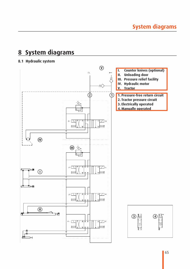
65
I
II
III
IV
V
12
3 4
System diagrams
8 System diagrams8.1 Hydraulic system
I. Counter knives (optional)II. Unloading doorIII. Pressure relief facilityIV. Hydraulic motorV. Tractor
1. Pressure-free return circuit2. Tractor pressure circuit3. Electrically operated4. Manually operated

66
I
II
III
IV
1
2
3
V
4
56
78
97 8
5 6
Troubleshooting list
8.2 Electrical system
I. hydraulic motorII. Unloading doorIII. Counter knife IV. Expansion / OptionalV. Weighing system
1. Green / yellow2. Fuse 8A3. Brown4. Blue5. Red6. Black7. Green8. White9. Protection
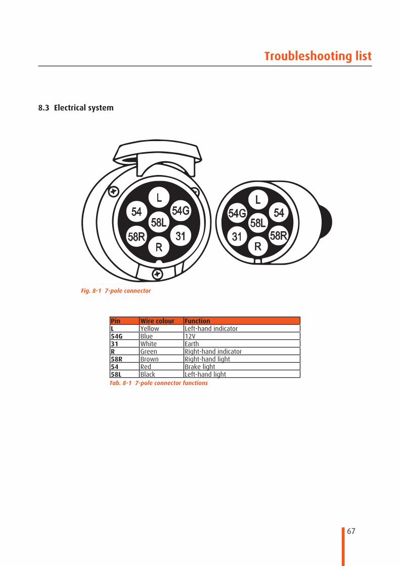
67
58R58R58L58L
54G54GLL
5454
3131RR
Troubleshooting list
8.3 Electrical system
Pin Wire colour FunctionL Yellow Left-hand indicator54G Blue 12V31 White EarthR Green Right-hand indicator58R Brown Right-hand light54 Red Brake light58L Black Left-hand lightTab. 8-1 7-pole connector functions
Fig. 8-1 7-pole connector

Peeters Landbouwmachines B.V.Tel +31 (0)76-504 66 66 Munnikenheiweg 47 www.peetersgroup.com
Fax +31 (0)76-504 66 99 4876NE Etten-Leur (NL) [email protected]