bim-odis / vse - csi internationalalternate,twasize=0 dfhpct...
TRANSCRIPT
(COPYRIGHT © 1995, B I MOYLE ASSOCIATES, INC.)
BIM-ODIS is a proprietary product of B I Moyle Associates, Inc. It cannot be reproduced, changed, copied,or stored in any form (including, but not limited to, copies on magnetic media) without the express priorwritten permission of B I Moyle Associates, Inc.
B I M - O D I S / V S E
ON-LINE CICS AND VSE SYSTEM STATUS DISPLAY
PROGRAM DESCRIPTIONAND
OPERATIONS MANUAL
Release 1.7

This documentation applies to Release 1.7of the program product BIM-ODIS.
Original Printing................................. 07/14/95Last Revised ....................................... 05/20/99

TABLE OF CONTENTS
GETTING STARTED .................................................................................................................................1Introduction ...........................................................................................................................................3New For This Release ...........................................................................................................................4Installation..............................................................................................................................................5
Loading Tape ..................................................................................................................................5CICS Table Entries .........................................................................................................................6Optional Entries..............................................................................................................................6ODISOPT Macro.............................................................................................................................7ODISOPT VM Parameters...........................................................................................................13
Terminal Support ................................................................................................................................13Release Dependencies.........................................................................................................................13
USING BIM-ODIS ....................................................................................................................................15How to Use ODIS ................................................................................................................................17
Fixed PF Keys ...............................................................................................................................17Variable PF Keys ..........................................................................................................................18Transaction Initiation By PF Key................................................................................................19Symbolic Unformatted Displays ................................................................................................20
Formatted Screen Descriptions..........................................................................................................22AID - CICS Automatic Initiate Descriptor ................................................................................23CHANQ - VSE Channel Queue..................................................................................................24COMREG - VSE Partition Communication Region .................................................................25CONSOL - VSE Console Display ...............................................................................................26CP - Issue VM CP Commands....................................................................................................27CSA - CICS Common System Area ...........................................................................................28DEMO - Demonstrate ODIS Displays .......................................................................................30DEST - CICS Destination Control Table....................................................................................31DLI - DL/I Online Control Blocks .............................................................................................32ENQ - CICS Enqueued Resources..............................................................................................33FILE - CICS File Control Table ...................................................................................................34FILE * - CICS File Control Table (Abbreviated) .......................................................................36FILE ** - CICS File Control Table Summary.............................................................................37ICE - CICS Interval Control Element.........................................................................................38LINE - Local and Remote Lines..................................................................................................39LOCK - VSE Lock Table ..............................................................................................................40LUB - VSE Logical Unit Block ....................................................................................................42MENU - List of All ODIS Displays ............................................................................................43PAM - CICS Page Allocation Map.............................................................................................45PART - VSE Partition Status .......................................................................................................47PF - Display Values of Variable PF Keys ..................................................................................48PIB - VSE Partition Information Block.......................................................................................49POWER - Issue POWER Commands.........................................................................................50PROB - Potential CICS Problems ...............................................................................................51PROG - CICS Processing Program Table ..................................................................................57PUB - VSE Physical Unit Block...................................................................................................58RESET - Reset Terminal Under VM...........................................................................................59SCAN - Scan Storage ...................................................................................................................60SEG - Segment CICS Printed Output.........................................................................................62SMCB - VSE Storage Management Control Block ...................................................................63SPACE - VSE Space Control Blocks ...........................................................................................64
TABLE OF CONTENTS
SR - CICS Shared Resources Control Block...............................................................................65SV - CICS Storage Violation Summary......................................................................................66SVA - VSE Shared Virtual Area..................................................................................................67SYSCOM - VSE System Communication Region .....................................................................68SYSTEM - Local and Remote Systems .......................................................................................69TABLES - CICS Table and Program Summary ........................................................................70TASK - CICS Active and Suspended Tasks ..............................................................................71TASK * - CICS Active and Suspended Tasks (Abbreviated) ..................................................73TERM - CICS Terminal Control Table .......................................................................................74TERM * - CICS Terminal Control Table (Abbreviated)...........................................................77TERM ** - CICS Terminal Control Table Summary.................................................................78TID - VSE Task-related Information ..........................................................................................79TRAK - Start or Stop ODISTRAK...............................................................................................81TRAN - CICS Program Control Table .......................................................................................82TRAN * - CICS Program Control Table (Abbreviated) ...........................................................83TS - CICS Temporary Storage.....................................................................................................84TSCOM - Temporary Storage Common Area ..........................................................................86VBUF - VTAM Buffer Pool Usage ..............................................................................................87VTAM - Issue VTAM Commands..............................................................................................88WATCH - Start or Stop Watchdog Mode..................................................................................90WHO - Identify the Terminal......................................................................................................91
Storage Display and Alteration .........................................................................................................92Storage Display.............................................................................................................................92Current Address Space ................................................................................................................93Cursor Positioning........................................................................................................................94Storage Alteration.........................................................................................................................94Storage Scan ..................................................................................................................................96
The ODISTRAK Feature .....................................................................................................................97ODISTRAK File Definition ..........................................................................................................97Selection of Time Intervals ..........................................................................................................98Starting ODISTRAK .....................................................................................................................98Batch Report JCL ..........................................................................................................................98Stopping ODISTRAK ...................................................................................................................99Parameter Card Syntax................................................................................................................99Parameter Cards ...........................................................................................................................99Archiving Data............................................................................................................................100Report Format .............................................................................................................................101Sample Reports ...........................................................................................................................101Resetting Statistics ......................................................................................................................104
Time-Initiated Mode .........................................................................................................................105Watchdog Mode.................................................................................................................................106
Message Suppression.................................................................................................................107Watchdog User Exits..................................................................................................................108
Using ODIS for Problem Determination.........................................................................................110Using ODIS to Analyze Storage Utilization...................................................................................115
Dynamic Storage Area ...............................................................................................................115Partition GETVIS Area...............................................................................................................117Resident Programs .....................................................................................................................117Resident Programs vs. Non-resident Programs .....................................................................118Transaction Storage....................................................................................................................119Temporary Storage.....................................................................................................................120

TABLE OF CONTENTS
Storage Violations ......................................................................................................................120Using ODIS as a Debugging Tool....................................................................................................122Using ODIS to Tune VSAM Files ....................................................................................................123
Control Interval Size ..................................................................................................................123Strings ..........................................................................................................................................124Buffers..........................................................................................................................................124Physical I/Os ..............................................................................................................................125Shared Resources .......................................................................................................................125GETVIS Usage ............................................................................................................................126Control Interval Splits................................................................................................................126Miscellaneous Considerations ..................................................................................................127Application Programming Considerations.............................................................................127
Ease of Use Features .........................................................................................................................129Features You May Have Missed......................................................................................................130Miscellaneous Considerations .........................................................................................................132Suspected Problems with ODIS.......................................................................................................134
MESSAGES ..............................................................................................................................................135


BIM-ODIS/VSE PROGRAM DESCRIPTION AND OPERATIONS MANUAL
Page 1
GETTING STARTED


BIM-ODIS/VSE PROGRAM DESCRIPTION AND OPERATIONS MANUAL
Introduction Page 3
IntroductionBIM-ODIS, or just “ODIS” (Online DISplay) is a CICS/VS program whose basicpurpose is to easily display, online, a wealth of realtime information about theoperation of the CICS system. As the operation of CICS is affected by othercomponents of the system, facilities are also provided to view some of the majorelements of VSE, VTAM, and DL/I.
In this document, BIM-ODIS is simply referred to as ODIS, DOS/VSE is referredto as VSE, OS/VS1 and MVS are referred to as MVS, and CICS/VS is referred toas CICS.
CICS maintains a surprisingly large amount of data in its various tables. As partof the shutdown process a small portion of this data is printed on SYSLST. ODISextends this facility to the online environment and provides the followingfeatures:
1. The amount of information available is many times greater than thatprovided in the shutdown report and the CSMT and CEMT transactions.
2. All of this information is instantly available online, at any time that it may beneeded.
3. Storage anywhere in the machine may be displayed (and even altered) inhexadecimal and character (“core dump” format).
4. Information about other system components is also available. This includesVSE, VTAM, and DL/I.
ODIS is useful not only for statistical purposes but also as an aid to tuning andproblem determination. And, since it reveals much of the internal operation ofCICS, it can function as a learning aid. ODIS is most useful for systemsprogrammers. However, some of its displays should also be helpful to a broadergroup of users including operators and programmers.
ODIS runs as a standard CICS transaction. It requires no modifications to anysoftware on the system and needs no “hooks” for its operation.
The objective behind ODIS is to give you a much information as you could everuse, and then some. For this reason, it is continually growing. Your suggestionsfor improvement are welcome, and all suggestions will be considered.
BIM-ODIS/VSE PROGRAM DESCRIPTION AND OPERATIONS MANUAL
Page 4 Summary of Enhancements
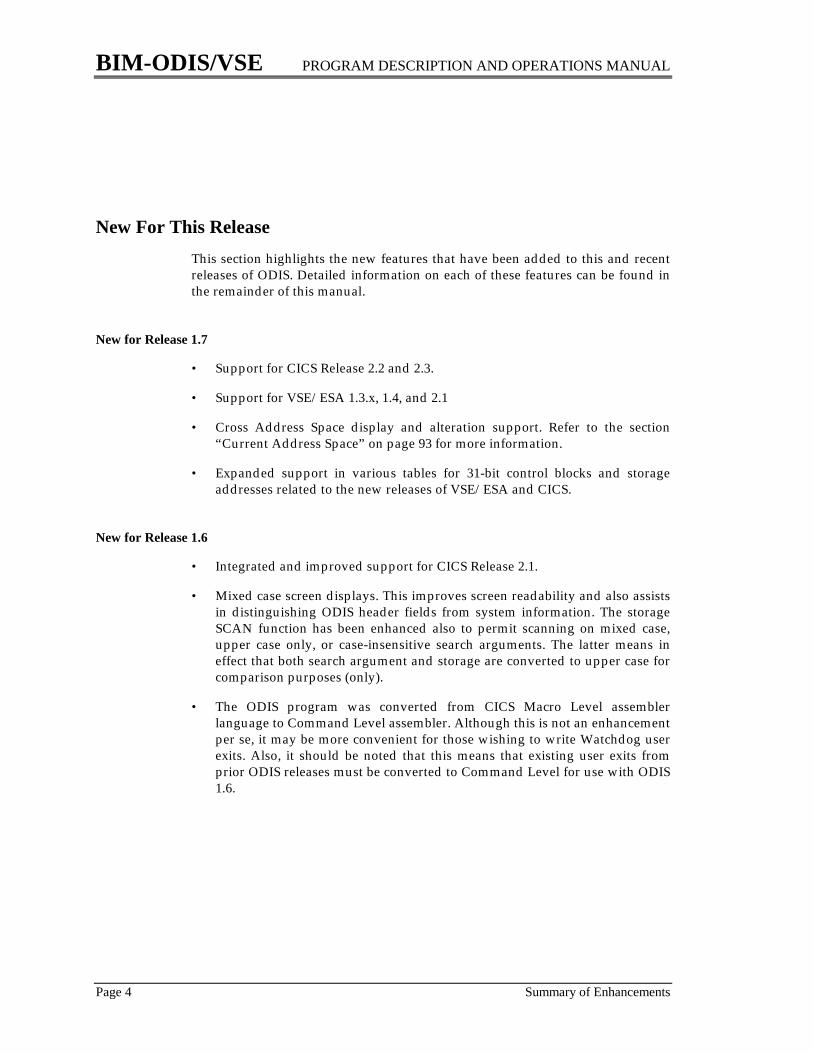
New For This ReleaseThis section highlights the new features that have been added to this and recentreleases of ODIS. Detailed information on each of these features can be found inthe remainder of this manual.
New for Release 1.7
• Support for CICS Release 2.2 and 2.3.
• Support for VSE/ESA 1.3.x, 1.4, and 2.1
• Cross Address Space display and alteration support. Refer to the section“Current Address Space” on page 93 for more information.
• Expanded support in various tables for 31-bit control blocks and storageaddresses related to the new releases of VSE/ESA and CICS.
New for Release 1.6
• Integrated and improved support for CICS Release 2.1.
• Mixed case screen displays. This improves screen readability and also assistsin distinguishing ODIS header fields from system information. The storageSCAN function has been enhanced also to permit scanning on mixed case,upper case only, or case-insensitive search arguments. The latter means ineffect that both search argument and storage are converted to upper case forcomparison purposes (only).
• The ODIS program was converted from CICS Macro Level assemblerlanguage to Command Level assembler. Although this is not an enhancementper se, it may be more convenient for those wishing to write Watchdog userexits. Also, it should be noted that this means that existing user exits fromprior ODIS releases must be converted to Command Level for use with ODIS1.6.
BIM-ODIS/VSE PROGRAM DESCRIPTION AND OPERATIONS MANUAL
Installation Page 5
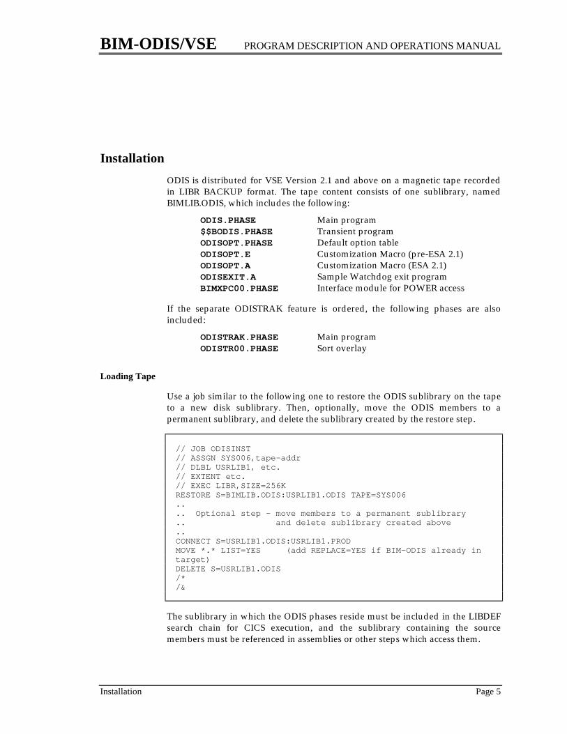
InstallationODIS is distributed for VSE Version 2.1 and above on a magnetic tape recordedin LIBR BACKUP format. The tape content consists of one sublibrary, namedBIMLIB.ODIS, which includes the following:
ODIS.PHASE Main program$$BODIS.PHASE Transient programODISOPT.PHASE Default option tableODISOPT.E Customization Macro (pre-ESA 2.1)ODISOPT.A Customization Macro (ESA 2.1)ODISEXIT.A Sample Watchdog exit programBIMXPC00.PHASE Interface module for POWER access
If the separate ODISTRAK feature is ordered, the following phases are alsoincluded:
ODISTRAK.PHASE Main programODISTR00.PHASE Sort overlay
Loading Tape
Use a job similar to the following one to restore the ODIS sublibrary on the tapeto a new disk sublibrary. Then, optionally, move the ODIS members to apermanent sublibrary, and delete the sublibrary created by the restore step.
// JOB ODISINST// ASSGN SYS006,tape-addr// DLBL USRLIB1, etc.// EXTENT etc.// EXEC LIBR,SIZE=256KRESTORE S=BIMLIB.ODIS:USRLIB1.ODIS TAPE=SYS006.... Optional step - move members to a permanent sublibrary.. and delete sublibrary created above..CONNECT S=USRLIB1.ODIS:USRLIB1.PRODMOVE *.* LIST=YES (add REPLACE=YES if BIM-ODIS already intarget)DELETE S=USRLIB1.ODIS/*/&
The sublibrary in which the ODIS phases reside must be included in the LIBDEFsearch chain for CICS execution, and the sublibrary containing the sourcemembers must be referenced in assemblies or other steps which access them.
BIM-ODIS/VSE PROGRAM DESCRIPTION AND OPERATIONS MANUAL
Page 6 Installation
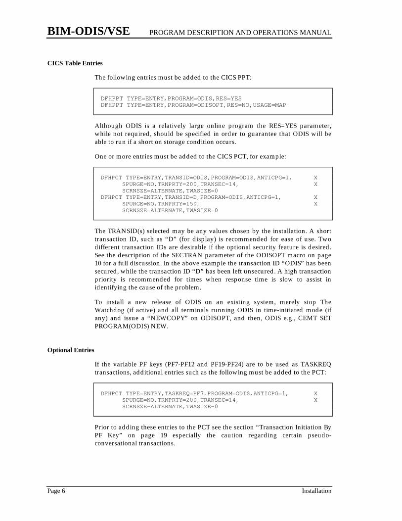
CICS Table Entries
The following entries must be added to the CICS PPT:
DFHPPT TYPE=ENTRY,PROGRAM=ODIS,RES=YESDFHPPT TYPE=ENTRY,PROGRAM=ODISOPT,RES=NO,USAGE=MAP
Although ODIS is a relatively large online program the RES=YES parameter,while not required, should be specified in order to guarantee that ODIS will beable to run if a short on storage condition occurs.
One or more entries must be added to the CICS PCT, for example:
DFHPCT TYPE=ENTRY,TRANSID=ODIS,PROGRAM=ODIS,ANTICPG=1, X SPURGE=NO,TRNPRTY=200,TRANSEC=14, X SCRNSZE=ALTERNATE,TWASIZE=0DFHPCT TYPE=ENTRY,TRANSID=D,PROGRAM=ODIS,ANTICPG=1, X SPURGE=NO,TRNPRTY=150, X SCRNSZE=ALTERNATE,TWASIZE=0
The TRANSID(s) selected may be any values chosen by the installation. A shorttransaction ID, such as “D” (for display) is recommended for ease of use. Twodifferent transaction IDs are desirable if the optional security feature is desired.See the description of the SECTRAN parameter of the ODISOPT macro on page10 for a full discussion. In the above example the transaction ID “ODIS” has beensecured, while the transaction ID “D” has been left unsecured. A high transactionpriority is recommended for times when response time is slow to assist inidentifying the cause of the problem.
To install a new release of ODIS on an existing system, merely stop TheWatchdog (if active) and all terminals running ODIS in time-initiated mode (ifany) and issue a “NEWCOPY” on ODISOPT, and then, ODIS e.g., CEMT SETPROGRAM(ODIS) NEW.
Optional Entries
If the variable PF keys (PF7-PF12 and PF19-PF24) are to be used as TASKREQtransactions, additional entries such as the following must be added to the PCT:
DFHPCT TYPE=ENTRY,TASKREQ=PF7,PROGRAM=ODIS,ANTICPG=1, X SPURGE=NO,TRNPRTY=200,TRANSEC=14, X SCRNSZE=ALTERNATE,TWASIZE=0
Prior to adding these entries to the PCT see the section “Transaction Initiation ByPF Key” on page 19 especially the caution regarding certain pseudo-conversational transactions.
BIM-ODIS/VSE PROGRAM DESCRIPTION AND OPERATIONS MANUAL
Installation Page 7
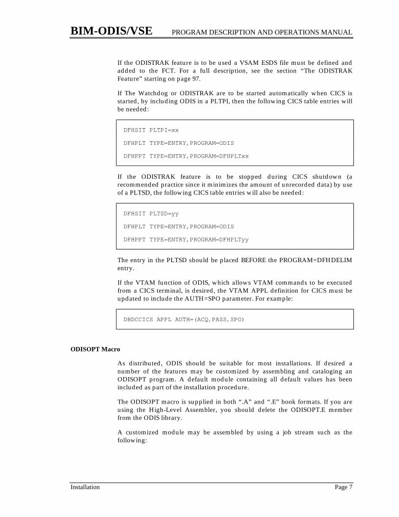
If the ODISTRAK feature is to be used a VSAM ESDS file must be defined andadded to the FCT. For a full description, see the section “The ODISTRAKFeature” starting on page 97.
If The Watchdog or ODISTRAK are to be started automatically when CICS isstarted, by including ODIS in a PLTPI, then the following CICS table entries willbe needed:
DFHSIT PLTPI=xx
DFHPLT TYPE=ENTRY,PROGRAM=ODIS
DFHPPT TYPE=ENTRY,PROGRAM=DFHPLTxx
If the ODISTRAK feature is to be stopped during CICS shutdown (arecommended practice since it minimizes the amount of unrecorded data) by useof a PLTSD, the following CICS table entries will also be needed:
DFHSIT PLTSD=yy
DFHPLT TYPE=ENTRY,PROGRAM=ODIS
DFHPPT TYPE=ENTRY,PROGRAM=DFHPLTyy
The entry in the PLTSD should be placed BEFORE the PROGRAM=DFHDELIMentry.
If the VTAM function of ODIS, which allows VTAM commands to be executedfrom a CICS terminal, is desired, the VTAM APPL definition for CICS must beupdated to include the AUTH=SPO parameter. For example:
DBDCCICS APPL AUTH=(ACQ,PASS,SPO)
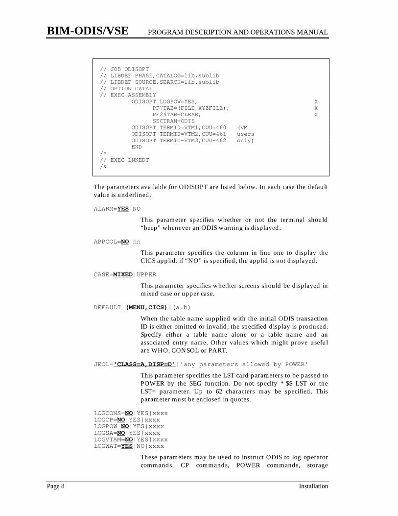
ODISOPT Macro
As distributed, ODIS should be suitable for most installations. If desired anumber of the features may be customized by assembling and cataloging anODISOPT program. A default module containing all default values has beenincluded as part of the installation procedure.
The ODISOPT macro is supplied in both “.A” and “.E” book formats. If you areusing the High-Level Assembler, you should delete the ODISOPT.E memberfrom the ODIS library.
A customized module may be assembled by using a job stream such as thefollowing:
BIM-ODIS/VSE PROGRAM DESCRIPTION AND OPERATIONS MANUAL
Page 8 Installation
// JOB ODISOPT// LIBDEF PHASE,CATALOG=lib.sublib// LIBDEF SOURCE,SEARCH=lib.sublib// OPTION CATAL// EXEC ASSEMBLY ODISOPT LOGPOW=YES, X PF7TAB=(FILE,XYZFILE), X PF24TAB=CLEAR, X SECTRAN=ODIS ODISOPT TERMID=VTM1,CUU=460 (VM ODISOPT TERMID=VTM2,CUU=461 users ODISOPT TERMID=VTM3,CUU=462 only) END/*// EXEC LNKEDT/&
The parameters available for ODISOPT are listed below. In each case the defaultvalue is underlined.
ALARM=YES|NO
This parameter specifies whether or not the terminal should“beep” whenever an ODIS warning is displayed.
APPCOL=NO|nn
This parameter specifies the column in line one to display theCICS applid. if “NO” is specified, the applid is not displayed.
CASE=MIXED|UPPER
This parameter specifies whether screens should be displayed inmixed case or upper case.
DEFAULT=(MENU,CICS)|(a,b)
When the table name supplied with the initial ODIS transactionID is either omitted or invalid, the specified display is produced.Specify either a table name alone or a table name and anassociated entry name. Other values which might prove usefulare WHO, CONSOL or PART.
JECL='CLASS=A,DISP=D'|'any parameters allowed by POWER'
This parameter specifies the LST card parameters to be passed toPOWER by the SEG function. Do not specify * $$ LST or theLST= parameter. Up to 62 characters may be specified. Thisparameter must be enclosed in quotes.
LOGCONS=NO|YES|xxxxLOGCP=NO|YES|xxxxLOGPOW=NO|YES|xxxxLOGSA=NO|YES|xxxxLOGVTAM=NO|YES|xxxxLOGWAT=YES|NO|xxxx
These parameters may be used to instruct ODIS to log operatorcommands, CP commands, POWER commands, storage

BIM-ODIS/VSE PROGRAM DESCRIPTION AND OPERATIONS MANUAL
Installation Page 9
alterations, VTAM commands and Watchdog messages.LOGxxx=YES will cause these messages to be written to the VSEconsole; in the current implementation of CICS they will also bewritten to SYSLST. LOGxxx=xxxx will cause these messages tobe logged to the Transient Data destination, xxxx. This may beany destination with variable length records and a maximumrecord length of at least 120 bytes. The standard destinationCSSL may be used to log messages to SYSLST. For each message,except Watchdog messages, the time, terminal ID and operatorID will be included in the messages. Note that Watchdogmessages are always written to the terminal specified by theWATTERM parameter; the LOGWAT parameter may be used tolog messages to an additional device. Note also that operatorcommands are always written (by VSE) to the console, makingthe specification of LOGCONS=YES unnecessary;LOGCONS=xxxx may be used, however, if it is desired to keep alog in Transient Data of all such commands.
LTA=NO|(a,b,c,d,e,f,g,h)
This parameter specifies the locations of additional LTAsprovided by non-IBM software. These will be displayed on theSYSCOM display. For installations without such a productLTA=NO should be specified. For installations with additionalLTAs specify the displacement of each LTA from the start of theIBM LTA. Up to eight additional LTAs may be specified. Forappropriate values see a Supervisor assembly listing or contactthe vendor.
PA2=PA2|PAn|PFnn
The PA2 key is used for the “toggle” feature. If this key has beengiven some other special use, such as the print request function,another PA or PF key may be used in its place.
PF1=(PF1,PF13)|(PFm,PFn)|PFmPF2=(PF2,PF14)|(PFm,PFn)|PFmPF3=(PF3,PF15)|(PFm,PFn)|PFmPF4=(PF4,PF16)|(PFm,PFn)|PFmPF5=(PF5,PF17)|(PFm,PFn)|PFmPF6=(PF6,PF18)|(PFm,PFn)|PFm
ODIS uses the fixed PF keys to facilitate changing displays. Theyare assigned in pairs for the convenience of those installationswith a mixture of 12-key and 24-key keyboards. Thus, with thedefault specification PF1 and PF13 are exactly equivalent.Installations without PF keys, or with a limited selection of PFkeys, or with many PF keys reserved for BMS paging functionsmay change the default values to any other PA or PF keys. Eachkey may have one (e.g. PF1=PF1), two (e.g. PF1=(PF1,PF13)), orno values (e.g. PF1=). It is the user's responsibility to insure thatthere is no duplication in the use of PA or PF keys. If the defaultvalues are modified the prompting line displayed at the bottomof the screen will not be changed. For an installation without PF

BIM-ODIS/VSE PROGRAM DESCRIPTION AND OPERATIONS MANUAL
Page 10 Installation
keys which must reduce the six PF keys (and one PA key) tothree (or less) PA keys the keys will probably prove to be mostuseful in the following order:
PF1 (the next key)PA2 (the toggle key)PF6 (the hex+char key)PF2 (the first key)PF3 (the miscellaneous key)PF4 and PF5 (the installation-defined keys)
PF4TAB=(CSA)|(a,b)PF5TAB=(TASK)|(c,d)
The PF4 and PF5 keys are used, by default, to display the CSAand TASK list, respectively. Any other display may be selectedby specifying a table name alone or a table name and anassociated entry name.
PF7TAB=(,)|(a,b)PF8TAB=(,)|(a,b)PF9TAB=(,)|(a,b)PF10TAB=(,)|(a,b)PF11TAB=(,)|(a,b)PF12TAB=(,)|(a,b)PF19TAB=(,)|(a,b)PF20TAB=(,)|(a,b)PF21TAB=(,)|(a,b)PF22TAB=(,)|(a,b)PF23TAB=(,)|(a,b)PF24TAB=(,)|(a,b)
The default ODISOPT macro does not define values for any ofthe variable PF keys. the installation may define its values forthese PF keys by specifying the desired table name alone or atable name and an associated entry name. As a convenience, oneof the variable PF keys may be used to clear the screen and endODIS operation on the terminal (just like the clear key) byspecifying CLEAR as the table name.
PLTPI=WATCH|(xxxxxx,yyyyyy)
This parameter specifies which processing is to be started whenODIS is executed from a startup PLT. Valid values are TRAK (forODISTRAK) and/or WATCH (for The WATCHDOG.)
SECHEX=NO|YES
NO specifies that all hexadecimal displays are to beunsecured and may be run under any transaction ID.
YES specifies that hexadecimal displays are secured and mayonly be run under the transaction ID specified in theSECTRAN parameter.
SECTRAN=NO|xxxx
Certain functions of ODIS may be secured. They are:

BIM-ODIS/VSE PROGRAM DESCRIPTION AND OPERATIONS MANUAL
Installation Page 11
storage alterationstorage display (if SECHEX=YES)CONSOL (commands)CPPOWERSEGTRAKVTAM commands (except for (D NET) commands)WATCH
The default is for all functions to be unsecured. The abovefunctions may be secured by specifying a CICS transaction ID(which must be in the PCT); in this case another transaction IDmay perform any non-secured functions, but an attempt toperform a secured function will be rejected with error messageODIS007. It is possible to completely disable the above functionsby specifying a transaction ID which does not exist in the PCT.
THxxxxx=
The following THxxxxx parameters specify threshold values which are used bythe PROB display and The Watchdog. A potential problem will be diagnosedonly if the associated threshold is exceeded. For a description of each problem seethe discussion of the PROB display on page 51.
parameter default problemname value unit of measure number
THAAMAX 75 of max active task limit 9THAMAX 75 % of max task limit 7THASOS 25 number of pages 2THAUXTS 90 % of capacity 24THCASPL 1 number of CA splits 25THCISPL 5 number of CI splits 26THDELAY 60 seconds 60THFETCH 3 number of times fetched 29THFREE 15 number of pages 23THSTOR 24 K bytes 18THVSOS 3 number of times VTAM was SOS 28THWBUFF 0 number of transactions 22THWCMAX 0 number of transactions 19THWENQ 0 number of transactions 15THWSTOR 0 number of transactions 12THWSTR 0 number of transactions 21
TIMMIN=0001|nnnn
This parameter specified the minimum value that can bespecified for the “Time-Initiated Mode”. See page 105.
BIM-ODIS/VSE PROGRAM DESCRIPTION AND OPERATIONS MANUAL
Page 12 Installation
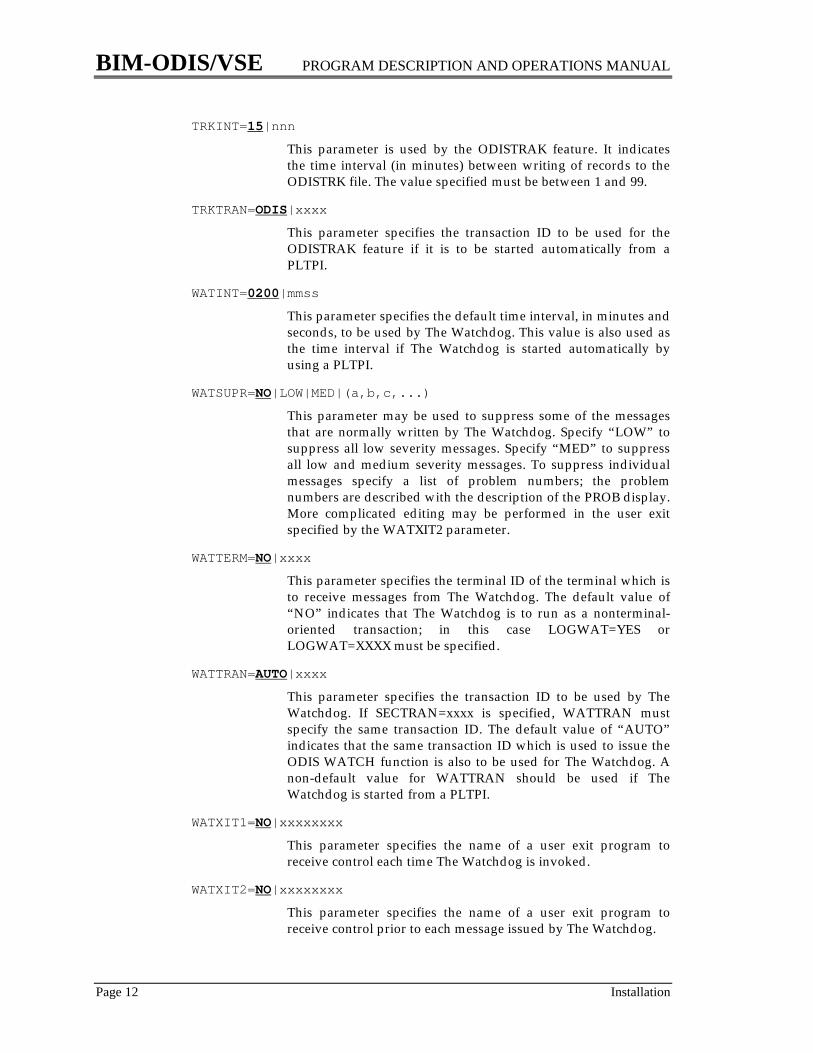
TRKINT=15|nnn
This parameter is used by the ODISTRAK feature. It indicatesthe time interval (in minutes) between writing of records to theODISTRK file. The value specified must be between 1 and 99.
TRKTRAN=ODIS|xxxx
This parameter specifies the transaction ID to be used for theODISTRAK feature if it is to be started automatically from aPLTPI.
WATINT=0200|mmss
This parameter specifies the default time interval, in minutes andseconds, to be used by The Watchdog. This value is also used asthe time interval if The Watchdog is started automatically byusing a PLTPI.
WATSUPR=NO|LOW|MED|(a,b,c,...)
This parameter may be used to suppress some of the messagesthat are normally written by The Watchdog. Specify “LOW” tosuppress all low severity messages. Specify “MED” to suppressall low and medium severity messages. To suppress individualmessages specify a list of problem numbers; the problemnumbers are described with the description of the PROB display.More complicated editing may be performed in the user exitspecified by the WATXIT2 parameter.
WATTERM=NO|xxxx
This parameter specifies the terminal ID of the terminal which isto receive messages from The Watchdog. The default value of“NO” indicates that The Watchdog is to run as a nonterminal-oriented transaction; in this case LOGWAT=YES orLOGWAT=XXXX must be specified.
WATTRAN=AUTO|xxxx
This parameter specifies the transaction ID to be used by TheWatchdog. If SECTRAN=xxxx is specified, WATTRAN mustspecify the same transaction ID. The default value of “AUTO”indicates that the same transaction ID which is used to issue theODIS WATCH function is also to be used for The Watchdog. Anon-default value for WATTRAN should be used if TheWatchdog is started from a PLTPI.
WATXIT1=NO|xxxxxxxx
This parameter specifies the name of a user exit program toreceive control each time The Watchdog is invoked.
WATXIT2=NO|xxxxxxxx
This parameter specifies the name of a user exit program toreceive control prior to each message issued by The Watchdog.

BIM-ODIS/VSE PROGRAM DESCRIPTION AND OPERATIONS MANUAL
Installation Page 13
DUMMY=DUMMY
This is optional, for those of you that like to end macros this way.
ODISOPT VM Parameters
On VM systems, if terminals which are not local BTAM 3270s are to be reset bythe RESET function of ODIS they must be defined in the ODISOPT specifications.To do so follow the above ODISOPT macro parameters with additional ODISOPTmacros, one per terminal, having the following format:
ODISOPT TERMID=xxxx,CUU=yyy
For each macro xxxx specifies the CICS terminal ID, and yyy specifies thecorresponding virtual address. There is no restriction on the number of terminalswhich can be specified in this manner.
Terminal SupportAll of the displays produced by ODIS are formatted for 80 byte wide terminals.ODIS will run on any of the 3270 family terminals (except 12-line model 1's), inSNA or non-SNA mode.
For many of its displays ODIS will take advantage of the larger screen sizes of themodel 3 and 4 screens (assuming SCRNSZE= ALTERNATE was specified in thePCT). On the model 5 ODIS will always run with the default (24x80) screen size.
ODIS will also run on any non-3270 terminal. However, if the terminal has awidth other than 80 columns the displays will be difficult to read because theyare formatted for 80 column terminals. The data stream does not contain newline, carriage return or other control characters.
Release DependenciesSince ODIS is deeply involved in the internal control blocks of CICS and VSE it isnormal for new releases of these products to require a corresponding new releaseof ODIS.
As of the time this manual was printed, there were releases of ODIS 1.7 availablefor VSE/ESA releases 1.1 through 2.1, and CICS releases 2.1 through 2.3.
Prior to upgrading to a new release of either VSE or CICS, contact your BIM salesrepresentative for the latest ODIS release requirements.

BIM-ODIS/VSE PROGRAM DESCRIPTION AND OPERATIONS MANUAL
Page 15
USING BIM-ODIS


BIM-ODIS/VSE PROGRAM DESCRIPTION AND OPERATIONS MANUAL
Using BIM-ODIS Page 17
How to Use ODISODIS is started by entering a transaction ID followed by a “table” name and,optionally, an “entry” name. These fields must be separated by a blank, commaor any other non-alphabetic, non-numeric character. For example:
ODIS FILE PAYMAST
The “table” name may be one of the following:
1. a table, such as CSA.2. the equivalent of a table, such as FILE or TERM.3. a 1-8 digit hexadecimal address or displacement, such as 4F6B99, 01000078,
or +2E. Both 24-bit and 31-bit addresses are supported.4. a symbol which is equivalent to a hexadecimal address, such as CWA or PC.
A full list of these symbols is found in the section “Symbolic UnformattedDisplays” on page 20.
5. a function to be performed, such as SCAN or WATCH.6. a static or dynamic partition ID such as BG, F1, F2, G1, etc.
The “entry” name is the name of the desired entry in the table. This would be afile name for the FILE table, a terminal ID for the TERM table, etc. If the “entry”name is omitted the first entry in the table will be displayed. For some tables,such as CSA, there is no entry name.
After the above information has been entered a display will be returned. Theformat of the displays and a sample of each screen are given in the section“Formatted Screen Descriptions” starting on page 22.
For non-3270 terminals ODIS will produce the specified display and endimmediately. For 3270 terminals ODIS will run in a conversational manner. Inthis case, the table and/or entry names at the top of the screen may be modifiedand the enter key hit to produce a different display.
Fixed PF Keys
For terminals with PF keys, PF keys are available as follows (unless changed bythe ODISOPT macro):
PF1 displays the next entry in the tablePF2 displays the first entry in the tablePF3 is used for special purposes and differs for each table.
BIM-ODIS/VSE PROGRAM DESCRIPTION AND OPERATIONS MANUAL
Page 18 Using BIM-ODIS
Note: For tables managed by the Table Management Program (TMP), the“next” entry, which is displayed by the PF1 key will not necessarily bethe next one in the assembly listing of the associated table. This affectsthe PROG, TRAN, and TERM displays.
For all displays, the following keys are always available:
PF4 displays the CSAPF5 displays the TASK listPF6 displays the same area of storage in hexadecimal and character
beginning at the address shown in the upper left hand corner ofthe screen
PA2 returns to the display just before the current display, thus givinga “toggle” function.
For terminals without PF keys, these may be simulated as follows:
PF1: setting the first character of the entry name to “+”PF2: setting the entry name to spaces or nullsPF3-PF6: setting the table and/or entry names as specifiedPA2: setting the first character of either the table name or entry
name to a period.
In the ODISOPT phase the above PA and PF keys may be changed to differentPA or PF keys; the tables displayed by the PF4 and PF5 keys may also bechanged. PF13-PF18 may also be used for the same purposes as PF1-PF6.
ODIS is terminated by hitting the clear key. If a variable PF key (see below) hasbeen set to “CLEAR” that PF key may also be used.
Variable PF Keys
The above PF keys (PF1-PF6 and PF13-PF18) are “fixed” in two respects:
1. Their meanings are predefined and cannot be changed, or can only bechanged by reassembling the ODISOPT macro.
2. Their meanings are the same for all terminals.
Variable PF keys (PF7-PF12 and PF19-PF24), on the other hand, have thefollowing characteristics:
1. Their values may be predefined in the ODISOPT macro or dynamicallydefined during CICS operation as follows:
a. a particular table is displayedb. the character string “PF7”, “PF21”, etc. is entered as the table name
This value will be retained as long as CICS is active.
2. Once defined, a PF key's value may be redefined by repeating step 1 above.
3. ODIS maintains a separate set of variable PF keys for each terminal.
BIM-ODIS/VSE PROGRAM DESCRIPTION AND OPERATIONS MANUAL
Using BIM-ODIS Page 19
It is possible to display the values assigned to a particular terminal's variable PFkeys by entered PF as the table name. It is possible to clear all of a particularterminal's PF keys by entering “PF CLEAR” and to reset all of a particularterminal's PF keys to the default values specified in the ODISOPT macro byentering “PF RESET”.
This usage of PF keys allows the terminal user to have multiple fingers toremember multiple displays and to easily switch from any one of these displaysto any other.
Transaction Initiation By PF Key
After the variable PF keys have been defined for a particular terminal, ODIS maybe initiated by hitting one of the variable PF keys. The table and entry which willbe displayed are the ones defined for the selected variable PF key at thatterminal. There are two ways to accomplish this:
1. Enter the ODIS transaction ID without a table or entry name, and instead ofhitting the enter key hit the desired variable PF key.
2. If the desired variable PF key has been defined in the PCT as a transaction:
DFHPCT TYPE=ENTRY,TASKREQ=PF24,PROGRAM=ODIS,...
merely hit the desired PF key. Caution: Some installations may not be able touse this method. If an installation uses pseudo-conversational transactionswhich place a transaction ID in the upper left hand corner of the screen,return to CICS and wait for a PF key to be hit, that PF key cannot be used as aTASKREQ transaction in the PCT by ODIS (or by any other transaction).Note that this restriction is not caused by ODIS; it is a consequence of thisparticular programming technique. This restriction does not apply to pseudo-conversational transactions which use the “return with next trans ID”method.
BIM-ODIS/VSE PROGRAM DESCRIPTION AND OPERATIONS MANUAL
Page 20 Using BIM-ODIS
Symbolic Unformatted Displays
In addition to those tables and control blocks which ODIS displays as formattedscreens, many others can be displayed in hexadecimal and character (“coredump” format). To do this enter the symbolic name of the tables as the tablename. ODIS will locate the table and display it. The following areas may bedisplayed in this manner:
ATCVT VTAM Communication Vector TableAVT VTAM Address Vector TableCVT VTAM Communication Vector Table (same as ATCVT)CWA CICS Common Work AreaDLIAL DLI Address ListDIB VSE Disk Information BlockGETVIS VSE System GETVIS area in SVAICCF ICCF Vector TableJA VSE Job Accounting Common TableJCT CICS Journal Control TableLTA VSE Logical Transient AreaMCT CICS Monitor Control TableOPFL CICS CSA Optional Features ListPC CICS Program Check/Abend Trace TablePCBA VSE Partition Control Block Address TablePMCOM VSE Page Management Communication AreaPSS VSE Partition Selection StringPTA VSE Physical Transient AreaPUBOWN VSE PUB Ownership TableRAS VSE Recoverability, Availability, Serviceability AreaSCBA VSE Space Control Block Address TableSDAID VSE SDAIDs Global TableSIT CICS System Initialization TableSMCOM VSE Storage Management Communication AreaSRT CICS System Recovery TableSSA CICS Static Storage Area Address ListTCTFX CICS Terminal Control Table PrefixTIBA VSE TIB Address TableTSBM CICS Temporary Storage Bit MapTST CICS Temporary Storage TableTSUT CICS Temporary Storage Unit Table (first such table)
Some of the formatted screens (documented in the section “Formatted ScreenDescriptions” starting on page 22) may also be accessed by an alternate name asfollows:
alternate standardBFRUSE VBUFCOMRG COMREGDCT DESTDL1 DLI
BIM-ODIS/VSE PROGRAM DESCRIPTION AND OPERATIONS MANUAL
Using BIM-ODIS Page 21
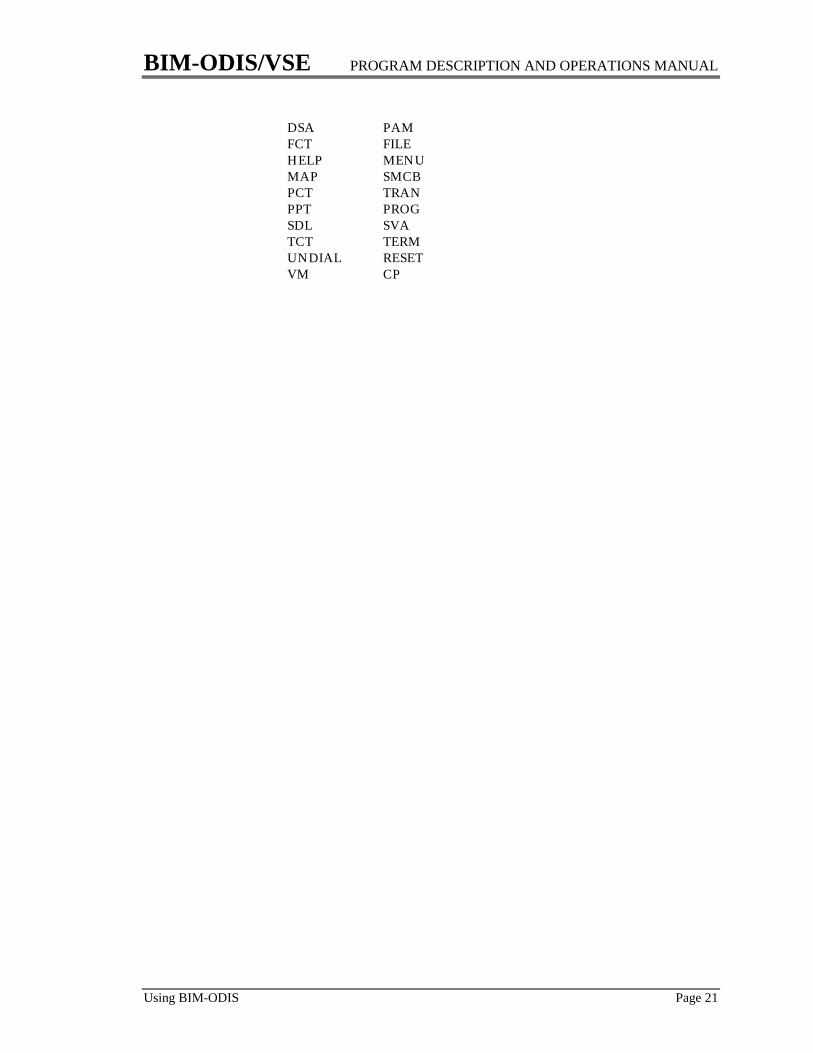
DSA PAMFCT FILEHELP MENUMAP SMCBPCT TRANPPT PROGSDL SVATCT TERMUNDIAL RESETVM CP

BIM-ODIS/VSE PROGRAM DESCRIPTION AND OPERATIONS MANUAL
Page 22 Formatted Screen Descriptions
Formatted Screen DescriptionsAll displays produced by ODIS have the following format:
1. The top line indicates the name of the table and entry being displayed alongwith the address in storage where it is located. If no address is appropriatethe address field will contain zeroes.
2. The body of the screen shows the detailed information contained in thespecified table and entry. There are two basic formats:
a. A columnar format with headings over each column. There will bemultiple entries on the screen with each entry occupying one line.
b. A field-by-field display where each field displayed has threecomponents:
i) its displacement into the tableii) an English description
iii) the value of the field
In addition, the bottom of the screen may contain a list of attributes.These are short English descriptions of the settings of individual bits, forexample whether a file is open or closed.
3. The bottom line is usually a prompting line which tells which PF keys areavailable and what functions they perform. If PF1, PF2 and PF3 areappropriate to the particular table they will be listed. PF4, PF5 and PF6 arealways available but are listed only if there is room for them on theprompting line. If the PF keys have been changed in the ODISOPT phase theprompting line will reflect the default values, not the installation-definedvalues.
On the following pages a sample of each screen produced by ODIS is given, inalphabetical order, along with a description of the table and its more useful andprominent fields. It must be recognized that this is an unofficial document. For anofficial description of these tables and fields the reader is directed to theappropriate IBM documentation.
Some of the tables produced by ODIS have been supplemented with informationthat does not exist in the table being displayed. These may generally be identifiedby the fact that they have no displacement associated with them. They have beenincluded because they are particularly valuable and would otherwise not bedisplayed by any ODIS screen. Examples are the CSA display fields 'CURRACTIVE TASKS' and 'CWA SIZE', and the fields labeled GETVIS ALLOC andGETVIS IN USE in the COMREG display.

BIM-ODIS/VSE PROGRAM DESCRIPTION AND OPERATIONS MANUAL
AID - CICS Automatic Initiate Descriptor Page 23
AID - CICS Automatic Initiate Descriptor
An AID describes a transaction which is to be started automatically. This istypically accomplished by the trigger level facility of Transient Data or by anInterval Control INITIATE or PUT (or Command Level START). In fact, an ICE(also displayed by ODIS) becomes an AID when it expires. Generally speaking anAID exists only for a short period of time and disappears. If this display showsany AIDs it probably indicates that there is some problem which is preventingthe associated work from being performed, for example:
The terminal or line is out of serviceThe transaction is disabledThe system is SOS or at maximum tasksAnother transaction is active at the terminalThe terminal is not in transceive or receive status
The number of AIDs in the system should rarely be so large that they will not fiton a single screen; however, if this happens, an entry name may be specified toindicate the number of AIDs to be skipped before the display begins.
Addr B0891C (3 ) Online DISplay of AID BIMCICST 08:41:19 V1.7G Owner of Addr Term Tran Data ID Origin System Term Tran Oper check
00AF8F80 PIRC CRSR ........ ICP INIT PIRC
PF3: ICE PF4: CSA PF5: Task list PF6: Hex+Char PA2: Toggle
BIM-ODIS/VSE PROGRAM DESCRIPTION AND OPERATIONS MANUAL
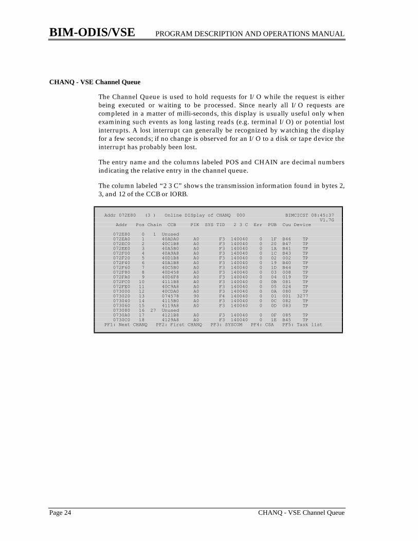
Page 24 CHANQ - VSE Channel Queue
CHANQ - VSE Channel Queue
The Channel Queue is used to hold requests for I/O while the request is eitherbeing executed or waiting to be processed. Since nearly all I/O requests arecompleted in a matter of milli-seconds, this display is usually useful only whenexamining such events as long lasting reads (e.g. terminal I/O) or potential lostinterrupts. A lost interrupt can generally be recognized by watching the displayfor a few seconds; if no change is observed for an I/O to a disk or tape device theinterrupt has probably been lost.
The entry name and the columns labeled POS and CHAIN are decimal numbersindicating the relative entry in the channel queue.
The column labeled “2 3 C” shows the transmission information found in bytes 2,3, and 12 of the CCB or IORB.
Addr 072E80 (3 ) Online DISplay of CHANQ 000 BIMCICST 08:45:37 V1.7G Addr Pos Chain CCB PIK SYS TID 2 3 C Err PUB Cuu Device
072E80 0 1 Unused 072EA0 1 40ADA0 A0 F3 140040 0 1F B46 TP 072EC0 2 40C1B8 A0 F3 140040 0 20 B47 TP 072EE0 3 40A5B0 A0 F3 140040 0 1A B41 TP 072F00 4 40A9A8 A0 F3 140040 0 1C B43 TP 072F20 5 40D1B8 A0 F3 140040 0 02 002 TP 072F40 6 40A1B8 A0 F3 140040 0 19 B40 TP 072F60 7 40C5B0 A0 F3 140040 0 1D B44 TP 072F80 8 40D458 A0 F3 140040 0 03 008 TP 072FA0 9 40D6F8 A0 F3 140040 0 04 019 TP 072FC0 10 4111B8 A0 F3 140040 0 0B 081 TP 072FE0 11 40C9A8 A0 F3 140040 0 05 024 TP 073000 12 40CDA0 A0 F3 140040 0 0A 080 TP 073020 13 074578 90 F4 140040 0 01 001 3277 073040 14 4115B0 A0 F3 140040 0 0C 082 TP 073060 15 4119A8 A0 F3 140040 0 0D 083 TP 073080 16 27 Unused 0730A0 17 4121B8 A0 F3 140040 0 0F 085 TP 0730C0 18 4129A8 A0 F3 140040 0 1E B45 TPPF1: Next CHANQ PF2: First CHANQ PF3: SYSCOM PF4: CSA PF5: Task list

BIM-ODIS/VSE PROGRAM DESCRIPTION AND OPERATIONS MANUAL
COMREG - VSE Partition Communication RegionPage 25
COMREG - VSE Partition Communication Region
The Communication Region is the main control block for each partition. (Othersare the PCB, PIB, and PIB2.)
The status of each partition is shown in the field(s) labeled RUN CODES. Eachtask has a two digit hexadecimal number that describes the state of the task.Some of the more common values are:
81 Waiting for the Logical Transient Area82 Waiting for an ECB or XECB (typically an I/O event)83 Ready to run
The TID display also shows the name of each task and an English description ofits run code.
The fields labeled GETVIS ALLOC and GETVIS IN USE tell how much of thepartition GETVIS area is being used. This is especially useful for determining theGETVIS requirements for CICS and VTAM. When the values of EXEC SIZE andGETVIS ALLOC are added together the sum will be about 2K less than thepartition size. This is not an error; it is caused by the fact that the first part of theGETVIS area is used for various control information and is not available forgeneral use.
The field labeled MAX FREE AREA indicates the size of the largest contiguousarea of free GETVIS storage. Since requests for storage must be allocatedcontiguously, a low value here may reveal insufficient GETVIS storage evenwhen there is a significant amount of unused storage.
Addr 004750 (3 ) Online DISplay of COMREG F9 BIMCICST 08:50:08 V1.7G00 Job date 06/09/95 40 PUB 32B0 ----- JCL options -----4F Sys date 060995160 48 FICL 15F8 ACANCL No LIST Yes0C User ........... 4A NICL 1605 ALIGN Yes LISTX No 00000000000 4C LUB 1AC4 CATAL No LOG No 00000000000 5A PIB 1528 CHARST 48C RLD No17 UPSI 00000000 60 DIB 4C44 DECK No SUBLIB AE18 Job name BIM-EDIT 7C PIB2 1458 DUMP Yes SXREF NoD8 Phase name BIMEDIT 74 JA table 00379D80 EDECK No SYM Yes20 PrbProgEnd 00827FFF A8 LUB extsn 0037C540 ERRS Yes SYSDMP No2E PIK 0040 C8 GETVIS ctl 009FC000 FASTTR YES TERM No6C Space ID 2 PCB Addr 00042CA0 JCANCL No XREF No8F Proc name ------ POWER ------ LINK No LINECT 56A0 POWER PCB 003B6F20 Pages spooled 0B8 Phase list 003824E0 Lines spooled 15 EXEC size= 160K SYSPARM Cards spooled 0 GETVIS alloc 1888K Ptn start 00800000 In use 1648KRun codes: 82 82 Max used 1680KTask IDs: 45 2A Free space 240KFeatures supported: CHANSW DASDFP TRKHOLD RPS Max ctg free 240KAttributes:
PF1: Next partition PF2: BG COMREG PF3: SYSCOM PF4: CSA PF5: Task list
BIM-ODIS/VSE PROGRAM DESCRIPTION AND OPERATIONS MANUAL
Page 26 CONSOL - VSE Console Display
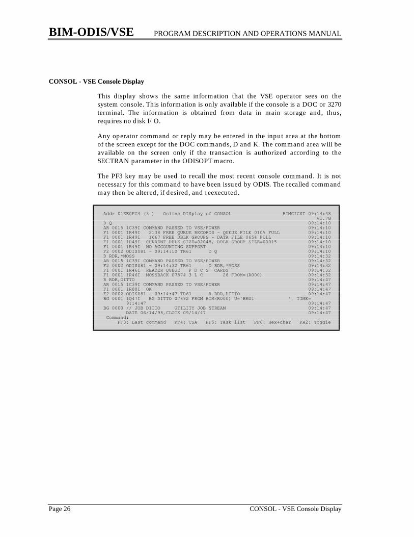
CONSOL - VSE Console Display
This display shows the same information that the VSE operator sees on thesystem console. This information is only available if the console is a DOC or 3270terminal. The information is obtained from data in main storage and, thus,requires no disk I/O.
Any operator command or reply may be entered in the input area at the bottomof the screen except for the DOC commands, D and K. The command area will beavailable on the screen only if the transaction is authorized according to theSECTRAN parameter in the ODISOPT macro.
The PF3 key may be used to recall the most recent console command. It is notnecessary for this command to have been issued by ODIS. The recalled commandmay then be altered, if desired, and reexecuted.
Addr 01EE0FC4 (3 ) Online DISplay of CONSOL BIMCICST 09:14:48 V1.7GD Q 09:14:10AR 0015 1C39I COMMAND PASSED TO VSE/POWER 09:14:10F1 0001 1R49I 2138 FREE QUEUE RECORDS - QUEUE FILE 010% FULL 09:14:10F1 0001 1R49I 1667 FREE DBLK GROUPS - DATA FILE 065% FULL 09:14:10F1 0001 1R49I CURRENT DBLK SIZE=02048, DBLK GROUP SIZE=00015 09:14:10F1 0001 1R49I NO ACCOUNTING SUPPORT 09:14:10F2 0002 ODIS081 - 09:14:10 TR61 D Q 09:14:10D RDR,*MOSS 09:14:32AR 0015 1C39I COMMAND PASSED TO VSE/POWER 09:14:32F2 0002 ODIS081 - 09:14:32 TR61 D RDR,*MOSS 09:14:32F1 0001 1R46I READER QUEUE P D C S CARDS 09:14:32F1 0001 1R46I MOSSBACK 07874 3 L C 26 FROM=(R000) 09:14:32R RDR,DITTO 09:14:47AR 0015 1C39I COMMAND PASSED TO VSE/POWER 09:14:47F1 0001 1R88I OK 09:14:47F2 0002 ODIS081 - 09:14:47 TR61 R RDR,DITTO 09:14:47BG 0001 1Q47I BG DITTO 07892 FROM BIM(R000) U='BM01 ', TIME= 9:14:47 09:14:47BG 0000 // JOB DITTO UTILITY JOB STREAM 09:14:47 DATE 06/14/95,CLOCK 09/14/47 09:14:47 Command: PF3: Last command PF4: CSA PF5: Task list PF6: Hex+char PA2: Toggle
BIM-ODIS/VSE PROGRAM DESCRIPTION AND OPERATIONS MANUAL
CP - Issue VM CP Commands Page 27
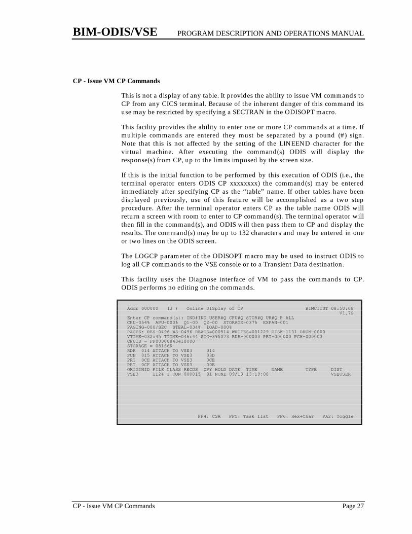
CP - Issue VM CP Commands
This is not a display of any table. It provides the ability to issue VM commands toCP from any CICS terminal. Because of the inherent danger of this command itsuse may be restricted by specifying a SECTRAN in the ODISOPT macro.
This facility provides the ability to enter one or more CP commands at a time. Ifmultiple commands are entered they must be separated by a pound (#) sign.Note that this is not affected by the setting of the LINEEND character for thevirtual machine. After executing the command(s) ODIS will display theresponse(s) from CP, up to the limits imposed by the screen size.
If this is the initial function to be performed by this execution of ODIS (i.e., theterminal operator enters ODIS CP xxxxxxxx) the command(s) may be enteredimmediately after specifying CP as the “table” name. If other tables have beendisplayed previously, use of this feature will be accomplished as a two stepprocedure. After the terminal operator enters CP as the table name ODIS willreturn a screen with room to enter to CP command(s). The terminal operator willthen fill in the command(s), and ODIS will then pass them to CP and display theresults. The command(s) may be up to 132 characters and may be entered in oneor two lines on the ODIS screen.
The LOGCP parameter of the ODISOPT macro may be used to instruct ODIS tolog all CP commands to the VSE console or to a Transient Data destination.
This facility uses the Diagnose interface of VM to pass the commands to CP.ODIS performs no editing on the commands.
Addr 000000 (3 ) Online DISplay of CP BIMCICST 08:50:08 V1.7GEnter CP command(s): IND#IND USER#Q CPU#Q STOR#Q UR#Q P ALLCPU-054% APU-000% Q1-00 Q2-00 STORAGE-037% EXPAN-001PAGING-000/SEC STEAL-034% LOAD-000%PAGES: RES-0496 WS-0496 READS=000514 WRITES=001229 DISK-1131 DRUM-0000VTIME=032:45 TTIME=046:44 SIO=395073 RDR-000003 PRT-000000 PCH-000003CPUID = FF00000843410000STORAGE = 08166KRDR 014 ATTACH TO VSE3 014PUN 015 ATTACH TO VSE3 03DPRT 0CE ATTACH TO VSE3 0CEPRT 0CF ATTACH TO VSE3 00EORIGINID FILE CLASS RECDS CPY HOLD DATE TIME NAME TYPE DISTVSE3 1124 T CON 000015 01 NONE 09/13 13:19:00 VSEUSER
PF4: CSA PF5: Task list PF6: Hex+Char PA2: Toggle
BIM-ODIS/VSE PROGRAM DESCRIPTION AND OPERATIONS MANUAL
Page 28 CSA - CICS Common System Area
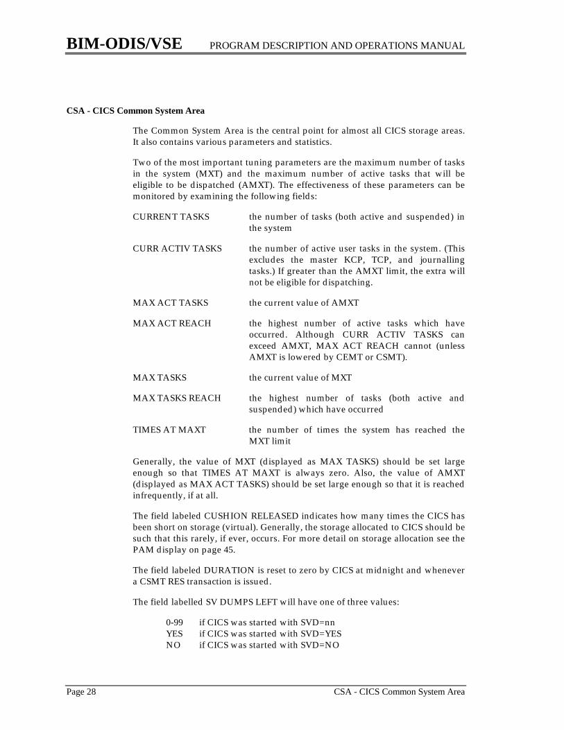
CSA - CICS Common System Area
The Common System Area is the central point for almost all CICS storage areas.It also contains various parameters and statistics.
Two of the most important tuning parameters are the maximum number of tasksin the system (MXT) and the maximum number of active tasks that will beeligible to be dispatched (AMXT). The effectiveness of these parameters can bemonitored by examining the following fields:
CURRENT TASKS the number of tasks (both active and suspended) inthe system
CURR ACTIV TASKS the number of active user tasks in the system. (Thisexcludes the master KCP, TCP, and journallingtasks.) If greater than the AMXT limit, the extra willnot be eligible for dispatching.
MAX ACT TASKS the current value of AMXT
MAX ACT REACH the highest number of active tasks which haveoccurred. Although CURR ACTIV TASKS canexceed AMXT, MAX ACT REACH cannot (unlessAMXT is lowered by CEMT or CSMT).
MAX TASKS the current value of MXT
MAX TASKS REACH the highest number of tasks (both active andsuspended) which have occurred
TIMES AT MAXT the number of times the system has reached theMXT limit
Generally, the value of MXT (displayed as MAX TASKS) should be set largeenough so that TIMES AT MAXT is always zero. Also, the value of AMXT(displayed as MAX ACT TASKS) should be set large enough so that it is reachedinfrequently, if at all.
The field labeled CUSHION RELEASED indicates how many times the CICS hasbeen short on storage (virtual). Generally, the storage allocated to CICS should besuch that this rarely, if ever, occurs. For more detail on storage allocation see thePAM display on page 45.
The field labeled DURATION is reset to zero by CICS at midnight and whenevera CSMT RES transaction is issued.
The field labelled SV DUMPS LEFT will have one of three values:
0-99 if CICS was started with SVD=nnYES if CICS was started with SVD=YESNO if CICS was started with SVD=NO
BIM-ODIS/VSE PROGRAM DESCRIPTION AND OPERATIONS MANUAL
CSA - CICS Common System Area Page 29
Addr A09600 (3 ) Online DISplay of CSA BIMCICST 09:12:34 V1.7G Tot tasks 621 58 Stall intrvl 60.000 74 Partn strt 00A000001CC Curr task # 621 64 Part exit 2.000 78 Partn end 013FFFFF1C8 Current tasks 4 8A Term scan dely .000 9C Op system VSE/ESA Curr activ tasks 5 9D Op system releas 61 C0 Max act tasks 12 CC Activ KP freq .201 9F CICS release 23 C2 Max act reach 4 1C4 Activ keypoints 1 C8 Opt.feat. 00A09A00 4A Max tasks 12 Runaway int 0.234 CWA size 5121CA Max tasks reach 6 1B4 Runaway tasks 01C0 Times at maxt 0 70 Cushion size 98K ------- VTAM ------ 7C Date 95/160 1D7 Cushion released 0 Appl ID BIMCICST 50 Time 09:12:34 1CF Getmains 24,177 Max RPLs posted 1 Duration 1:00:46 1D3 Freemains 22,627 Times at max 691B6 Relative day 0 1D9 Getm req queued 0 Dynam ACB opens 01DF Program checks 1 1F0 TD tracks used 0 Times VTAM SOS 01E1 Dumps taken 2 SV dumps left Yes Dump data set A
---------------------------------- Attributes ----------------------------------
PF3: SYSCOM PF4: CSA PF5: Task list PF6: Hex+char PA2: Toggle
BIM-ODIS/VSE PROGRAM DESCRIPTION AND OPERATIONS MANUAL
Page 30 DEMO - Demonstrate ODIS Displays
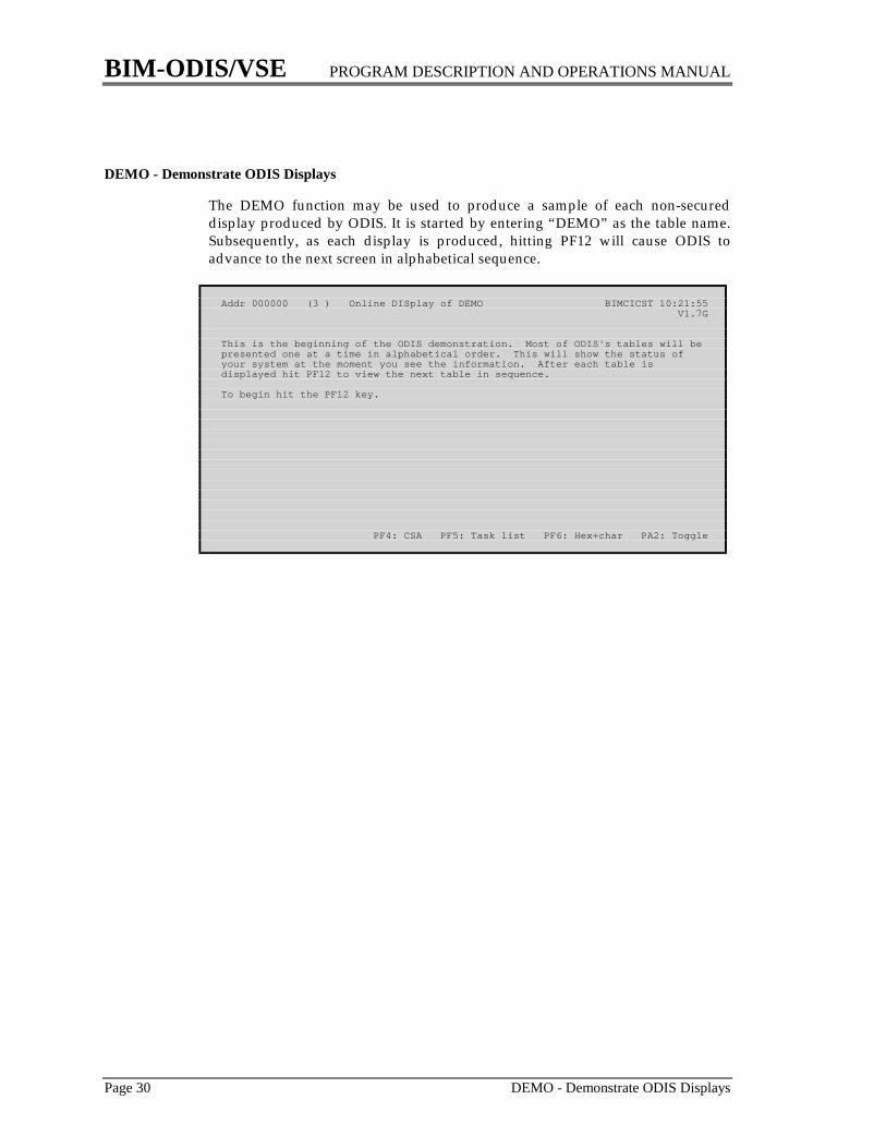
DEMO - Demonstrate ODIS Displays
The DEMO function may be used to produce a sample of each non-secureddisplay produced by ODIS. It is started by entering “DEMO” as the table name.Subsequently, as each display is produced, hitting PF12 will cause ODIS toadvance to the next screen in alphabetical sequence.
Addr 000000 (3 ) Online DISplay of DEMO BIMCICST 10:21:55 V1.7G
This is the beginning of the ODIS demonstration. Most of ODIS's tables will bepresented one at a time in alphabetical order. This will show the status ofyour system at the moment you see the information. After each table isdisplayed hit PF12 to view the next table in sequence.
To begin hit the PF12 key.
PF4: CSA PF5: Task list PF6: Hex+char PA2: Toggle

BIM-ODIS/VSE PROGRAM DESCRIPTION AND OPERATIONS MANUAL
DEST - CICS Destination Control Table Page 31
DEST - CICS Destination Control Table
The Destination Control Table is used to control Transient Data destinations.Each Transient Data destination represents a sequential file on disk, tape, card, orprinter.
The field labeled “MAX L” is the maximum data length.The field labeled “I TCA” is the address of the input TCA.The field labeled “O TCA” is the address of the output TCA.
Addr A89D50 (3 ) Online DISplay of DEST CSSL BIMCICST 10:23:58 V1.7G ----------- Intrapartition ------------ ---- Extra ----Name Type RSL Sta Writes Queue Trig Tran Term I TCA O TCA Open Res DTF
CSSL Extra 0 Ena 360 Init Y 00A88070CSSM Extra 0 Ena 0 Defr Y 00A88310CSSN Extra 0 Ena 0 Defr Y 00A88BF8BIMD Extra 0 Ena 0 Init Y 00A894E0CPLI Extra 0 Ena 0 Init Y 00A88150CPLD Extra 0 Ena 0 Init Y 00A88230L86P Intra 0 Ena 0 0 1 I$$6 L86P 00000000 00000000RCPH Intra 0 Ena 0 0 0 00000000 00000000RCLG Intra 0 Ena 0 0 0 00000000 00000000$TW$ Intra 0 Ena 0 0 0 00000000 00000000CADL Indir 0 Ena 180 Dest=CSSLCSDL Indir 0 Ena 0 Dest=CSSLCSMT Indir 0 Ena 134 Dest=CSSLCSTL Indir 0 Ena 34 Dest=CSSLCSML Indir 0 Ena 11 Dest=CSSLIESL Intra PU Ena 0 0 1 IESX 00000000 00000000IESM Indir 0 Ena 0 Dest=IESNIESN Indir 0 Ena 0 Dest=CSSLPF1: Next dest PF2: First dest PF4: CSA PF5: Task list PF6: Hex+char
BIM-ODIS/VSE PROGRAM DESCRIPTION AND OPERATIONS MANUAL
Page 32 DLI - DL/I Online Control Blocks
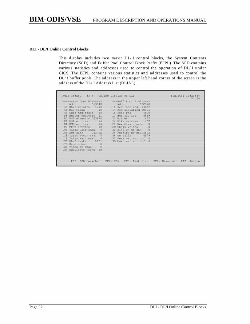
DLI - DL/I Online Control Blocks
This display includes two major DL/I control blocks, the System ContentsDirectory (SCD) and Buffer Pool Control Block Prefix (BFPL). The SCD containsvarious statistics and addresses used to control the operation of DL/I underCICS. The BFPL contains various statistics and addresses used to control theDL/I buffer pools. The address in the upper left hand corner of the screen is theaddress of the DL/I Address List (DLIAL).
Addr C63AF0 (3 ) Online DISplay of DLI BIMCICST 10:23:58 V1.7G------Sys Cont Dir----- ---Buff Pool Prefix--- Addr C63940 Addr C3C570 60 DL/I Version 1.70 10 Req received 93642 66 Max tasks 10 14 Req satisfied 60891 68 Curr max tasks 10 18 Read req 6500 D8 Buffer subpools 11 1C Buf alt req 4869 DC PSB directry C63BA0 20 Writes 457 E2 PSB entries 14 24 Blks written 457 EA DMB entries 14 28 New blks creatd 0 F2 PPST entries 10 2C Chain writes 0106 Tasks wait cmax 0 30 Blks on wt chn 0108 Act addr C6379A 34 Retriev by key13572118 Tasks assgn PPST 0 38 GN calls 497911A Tasks wait maxt 0 3C Perm wrt err buf 0178 DL/I tasks 2831 3D Max wrt err buf 017C Deadlocks 0180 Times at cmax 0184 Duplicate PSB'S 19
PF3: SCD hex+char PF4: CSA PF5: Task list PF6: Hex+char PA2: Toggle

BIM-ODIS/VSE PROGRAM DESCRIPTION AND OPERATIONS MANUAL
ENQ - CICS Enqueued Resources Page 33
ENQ - CICS Enqueued Resources
Information about enqueued resources is maintained as a chain of QueueElement Areas (QEAs) and does not form a proper table as such. An enqueue isperformed by an application program when it is necessary to insure that only onetask is accessing a particular resource. If tasks are waiting for a resource for anextended period of time it probably, but not necessarily, represents a problem tobe investigated.
The resource name displayed is restricted to 18 characters; if the name is longer itis truncated on the right and followed by a plus (+) sign to indicate that fact.Similarly, if more than 10 tasks are waiting for a resource, only the first 10 aredisplayed, and a plus (+) sign appears at the end.
The USE field indicates how many times the owning task has enqueued on theresources and is almost always set to one.
The OWNER and TASKS WAITING indicate the terminal ID for terminal-oriented tasks and the transaction ID for non terminal-oriented tasks.
The number of enqueues in the system should rarely be so large that they will notfit on a single screen; however, if this happens, an entry name may be specified toindicate the number of enqueues to be skipped before the display begins.
Addr AD1730 (3 ) Online DISplay of ENQ BIMCICST 10:31:05 V1.7GName of resource Owner Use ----------------- Tasks waiting -----------------
BIMSWAPX SWAX 1 No tasks waitingBIMECHOX ECHX 1 No tasks waitingBETA M206 1 M205 M214 M203 M210 M212GAMMA M020 2 No tasks waitingALPHA M213 1 M206
PF4: CSA PF5: Task list PF6: Hex+char PA2: Toggle
BIM-ODIS/VSE PROGRAM DESCRIPTION AND OPERATIONS MANUAL
Page 34 FILE - CICS File Control Table
FILE - CICS File Control Table
The FCT contains one entry for each file that is accessed through CICS. Fileswhich are accessed by non-standard methods without using the CICS Macro orCommand Level interfaces will probably not be found in the FCT.
The READ REQUESTS field includes only random reads. The BROWSEREQUESTS field includes the READNEXT and READPREV commands; it doesnot include the STARTBR, ENDBR and RESETBR commands.
The center column is only displayed if the file is a non-DL/I VSAM file. Most ofthe fields in the right hand column are only displayed for open VSAM files. Thisinformation is taken from VSAM (not CICS) control blocks which are built byVSAM at the time the file is opened under CICS. Since these control blocks do notexist for a closed file, this area of the screen will be blank if the file is closed. Thefields from % FREE SPACE through TOTAL RECS are determined at the time thefile is opened and will not change until the file is closed. The fields from DELETRECS through CA SPLITS reflect just the activity by CICS since the file wasopened. These fields can be particularly valuable for tuning VSAM files. ForVSAM files that use Shared Resources additional information from the SharedResources Control Block is available in the SR display.
The fields relating to VSAM strings and buffers should be of particular interest.Generally, speaking, these should be maintained so that tasks rarely, if ever, waitfor strings or buffers. For more information, see the section “Using ODIS to TuneVSAM Files” starting on page 123.
The attribute ACB OPEN (or ACB CLOSED) is taken directly from the VSAMACB and is correct. The attribute OPEN (or CLOSED) is taken from CICS's FCTand should match the VSAM ACB. If not, it probably indicates a problem in CICSor VSAM.
If any tasks are waiting for exclusive control (of a VSAM control interval), VSAMstrings, or VSAM buffers, the attributes portion of the display will indicate thisfact and, if running on a 3270, sound the alarm.

BIM-ODIS/VSE PROGRAM DESCRIPTION AND OPERATIONS MANUAL
FILE - CICS File Control Table Page 35
Addr A78248 (3 ) Online DISplay of FILE IESCNTL BIMCICST 10:48:37 VSE.CONTROL.FILE -------- VSAM -------- Data Index10 Record length 1,000 5C EXCPAD wait ECB 40 % free space CI 0 016 Rel key positn 0 63 CI split wt ECB 44 % free space CA 0 012 Key length 12 4C Buffer wait ECB 00 CI size 4096 51220 Active DWEs 0 50 Curr wait buff 0 Index levels - 214 Max str wait ECB 40 52 High wait buff 0 Extents 2 115 Psudo max str wt 40 54 Totl wait buff 0 Share option 2 218 User journal ID 0 68 Active strings 0 Buffers 35 424 Read requests 0 6C Max strings 2 Total recs 204 328 Add requests 0 6E Upt/add max str 2 Delet recs 0 02C Updt requests 0 6A Curr wait str 0 Insrt recs 0 038 Get updt reqs 0 78 High wait str 0 Updat recs 0 03C Browse reqsts 0 70 Totl wait str 0 Retrv recs 0 074 Deletes 0 90 ACB begin A782D8 EXCPs 0 0 Total I/O 0 CI splits 0 0 CA splits 0 0Valid accesses: Read Update Add Browse Delete---------------------------------- Attributes ----------------------------------VSAM KSDS Enabled Open by CEMT OpenACB open Var length recs Unblocked recs
PF1: Next file PF2: First file PF3: File summary PF4: CSA PF5: Task list
BIM-ODIS/VSE PROGRAM DESCRIPTION AND OPERATIONS MANUAL
Page 36 FILE * - CICS File Control Table (Abbreviated)
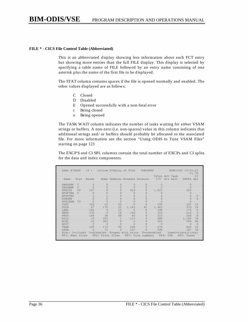
FILE * - CICS File Control Table (Abbreviated)
This is an abbreviated display showing less information about each FCT entrybut showing more entries than the full FILE display. This display is selected byspecifying a table name of FILE followed by an entry name consisting of oneasterisk plus the name of the first file to be displayed.
The STAT column contains spaces if the file is opened normally and enabled. Theother values displayed are as follows:
C ClosedD DisabledE Opened successfully with a non-fatal errorc Being closedo Being opened
The TASK WAIT column indicates the number of tasks waiting for either VSAMstrings or buffers. A non-zero (i.e. non-spaces) value in this column indicates thatadditional strings and/or buffers should probably be allocated to the associatedfile. For more information see the section “Using ODIS to Tune VSAM Files”starting on page 123
The EXCP'S and CI SPL columns contain the total number of EXCPs and CI splitsfor the data and index components.
Addr A79D68 (3 ) Online DISplay of FILE *DBUGPRF BIMCICST 10:51:21 V1.7G Total Act Task CI Name Stat Reads Adds Updates Browses Deletes I/O str wait EXCPs spl
DBUGPRF C 0 0 0 0 0 0 0DBUGEMP C 0 0 0 0 0 0 0DFHCSD CU 107 0 0 914 0 1,021 225APSFTRH C 0 0 0 0 0 0 0APSFTRD 2 1 0 0 1 4 6 0BIMJMS 0 0 0 0 0 0 4 0DOSISAM CU 0 0 0 0 0 0 0CUST 126 12 52 0 0 190 231 12CDIR 67 170 22 1,183 41 1,483 970 14LABL 183 0 15 0 0 198 175 0REFR 170 5 18 150 0 343 216 3PROD 184 38 48 40 0 310 244 8BILL 10 352 1 113 9 485 1,194 78RCAL 10 303 0 0 9 322 594 46ACCT 0 0 0 0 0 0 0 0TRAN 169 172 96 238 3 678 844 33LEGR 0 71 0 227 0 298 347 18Stat: C=closed D=disabled E=open with error U=unenabled Lower=transitionalPF1: Next files PF2: First files PF3: File summary PF4: CSA PF5: Tasks
BIM-ODIS/VSE PROGRAM DESCRIPTION AND OPERATIONS MANUAL
FILE ** - CICS File Control Table Summary Page 37
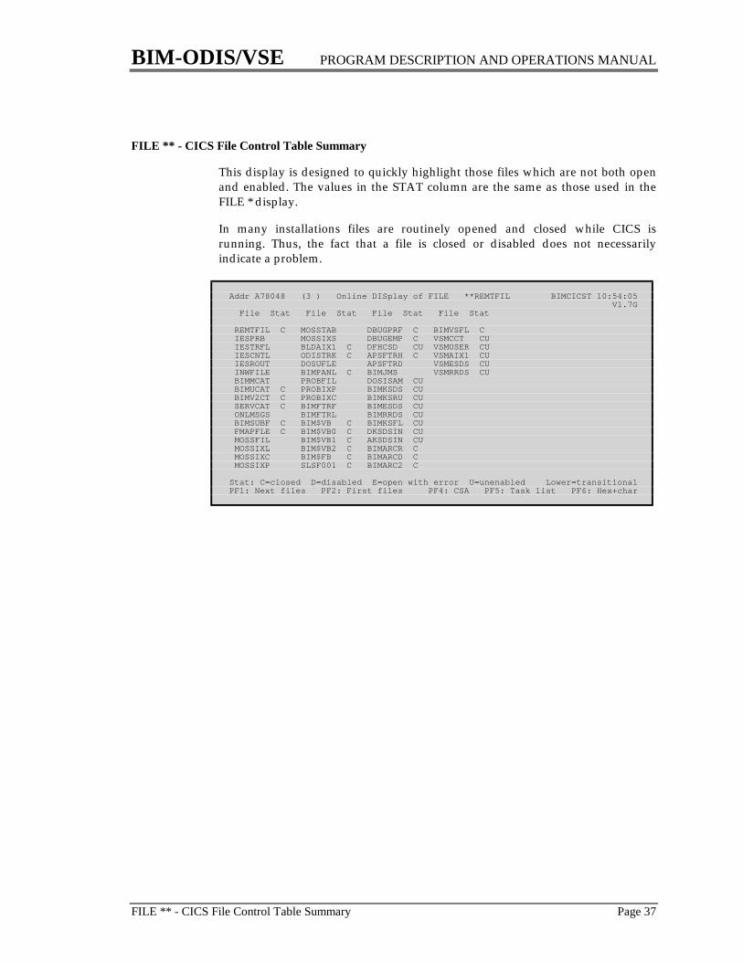
FILE ** - CICS File Control Table Summary
This display is designed to quickly highlight those files which are not both openand enabled. The values in the STAT column are the same as those used in theFILE * display.
In many installations files are routinely opened and closed while CICS isrunning. Thus, the fact that a file is closed or disabled does not necessarilyindicate a problem.
Addr A78048 (3 ) Online DISplay of FILE **REMTFIL BIMCICST 10:54:05 V1.7G File Stat File Stat File Stat File Stat
REMTFIL C MOSSTAB DBUGPRF C BIMVSFL C IESPRB MOSSIXS DBUGEMP C VSMCCT CU IESTRFL BLDAIX1 C DFHCSD CU VSMUSER CU IESCNTL ODISTRK C APSFTRH C VSMAIX1 CU IESROUT DOSUFLE APSFTRD VSMESDS CU INWFILE BIMPANL C BIMJMS VSMRRDS CU BIMMCAT PROBFIL DOSISAM CU BIMUCAT C PROBIXP BIMKSDS CU BIMV2CT C PROBIXC BIMKSRU CU SERVCAT C BIMFTRF BIMESDS CU ONLMSGS BIMFTRL BIMRRDS CU BIMSUBF C BIM$VB C BIMKSFL CU FMAPFLE C BIM$VB0 C DKSDSIN CU MOSSFIL BIM$VB1 C AKSDSIN CU MOSSIXL BIM$VB2 C BIMARCR C MOSSIXC BIM$FB C BIMARCD C MOSSIXP SLSF001 C BIMARC2 C
Stat: C=closed D=disabled E=open with error U=unenabled Lower=transitionalPF1: Next files PF2: First files PF4: CSA PF5: Task list PF6: Hex+char

BIM-ODIS/VSE PROGRAM DESCRIPTION AND OPERATIONS MANUAL
Page 38 ICE - CICS Interval Control Element
ICE - CICS Interval Control Element
An ICE describes a transaction which is to be started at some time in the future.(When the time expires the ICE becomes an AID; see the description of AID onpage 23.)
The DATA ID will also be found in Temporary Storage (on the TS display) if thetask is to be started with data (via a Macro Level DFHIC TYPE=PUT orCommand Level START with data). If auxiliary Temporary Storage is notsupported this data will be placed in main storage where it can be viewed inhexadecimal and character format.
The number of ICEs in the system should rarely be so large that they will not fiton a single screen; however, if this happens, an entry name may be specified toindicate the number of ICEs to be skipped before the display begins.
Addr AD1510 (3 ) Online DISplay of ICE BIMCICST 10:57:50 V1.7G Owner of Addr Term Tran Data ID Expires Time left Type Term Tran Status
00AD1510 .... PRTA DTA*AUTO 10:58:29 :39 INIT On chain00AD1560 .... AFXT DF000012 10:59:04 1:14 INIT On chain00AD1690 .... CRSQ DF000008 18:46:31 7:48:41 INIT On chain
PF3: AID PF4: CSA PF5: Task list PF6: Hex+char PA2: Toggle

BIM-ODIS/VSE PROGRAM DESCRIPTION AND OPERATIONS MANUAL
LINE - Local and Remote Lines Page 39
LINE - Local and Remote Lines
This display shows the totals for each line in the system. Lines are defined asfollows:
1. a remote BTAM line2. a local BTAM line, which does not represent a physical line but a group of
terminals defined in the TCT as a line3. all VTAM terminals are considered to be part of a single line4. all other terminals are generally defined as one terminal per line
For the VTAM line the STAT column indicates whether the VTAM ACB is OPENor CLOSed; for other lines it indicates whether the line is IN service or OUT ofservice.
In systems with a mixture of pseudo-conversational and true conversationaltransactions, the INPUT and OUTPUT MESSAGE totals may be a more accurateindication of system activity than the total number of transactions.
The ACTIVE TERMS column is an attempt to indicate how many terminals arecurrently in use. It includes the number of terminals with transactions running orwith the “next trans ID” field set; this should include all transactions except thosewhich utilize the method of placing the next trans ID in the upper left handcorner of the screen. The ACTIVE USERS column indicates how many users havesigned on (using CSSN).
See the description of the TERM display on page 74 for peculiarities of thetransaction and message counts.
Addr 000000 (3 ) Online DISplay of LINE BIMCICST 11:00:54 V1.7G First Terms ---Messages-- Xmit ---Active--- Line term Stat OS Trans Input Output errs Polls Users Terms
00A00DE0 CNSL In 0 0 0 0 0 0 0 00A00E3C L001 In 4 0 0 0 0 0 0 0 00A00EAC T001 Out 0 0 0 0 0 0 0 0 PIRC TR1 0 0 0 0 0 0 0 VTAM BE03 Open 0 9 27 30 0 1 2
Total 4 9 27 30 0 0 1 2
PF4: CSA PF5: Task list PF6: Hex+char PA2: Toggle
BIM-ODIS/VSE PROGRAM DESCRIPTION AND OPERATIONS MANUAL
Page 40 LOCK - VSE Lock Table
LOCK - VSE Lock Table
The Lock Table contains information used to control access to certain resources.Its function is similar to the ENQ facilities of CICS. The main user of locks isVSAM; VSAM resources are those which begin with “V”. Generally, resourcesare locked and unlocked in such a manner that they are not a concern for aninstallation. However, when a partition is waiting for a resource it may bedesirable to identify the owner and, possibly, the resource.
A resource may be locked within one VSE system or across multiple VSEsystems. The Lock Table on a given VSE system contains the control informationfor those resources, internal and external, which it owns. The entries for externalresources which it owns (but not those it is waiting for) are also stored on the lockfile.
A partition (or task) waiting for an internal resource will be shown on the PARTor TID display with a status of 8E WAIT LOCK FREE. A partition (or task)waiting for an external resource will be shown on the PART or TID display witha status of 82, 83, or 8B; unfortunately, these are common status values and donot uniquely describe this condition.
The entry name may be one of the following:
1. a 1-3 digit relative position in the Lock Table2. EXCL to restrict the display to resources which are owned exclusively3. NONVSAM to restrict the display to nonVSAM resources4. VSAM to restrict the display to VSAM resources5. WAIT to restrict the display to those resources for which one or more tasks
are waiting. For this display only, tasks waiting for external resources whichare not recorded in this VSE system's lock table, if any, will follow the entriesfrom the lock table; in this case the ADDR column indicates the address ofthe DTL instead of the address of an entry in the Lock Table. Only partitionswhich are addressable to the CICS system running ODIS will be shown; thisincludes partitions running in the same space plus partitions running in theshared space.
The POS column indicates the position of the associated entry relative to the firstentry in the lock table. Entries which are not in use will not be displayed; thus,there may be gaps in the numbers shown in the POS column.
The RESOURCE NAME is the name of the resource. Non-displayable charactersare represented as periods. The category of the resource may be identified by thefirst character of the name:
A basic access methods e.g. VTOC maintenanceB data securityC LibrarianDLB label area routinesI POWERV VSAM

BIM-ODIS/VSE PROGRAM DESCRIPTION AND OPERATIONS MANUAL
LOCK - VSE Lock Table Page 41
For more information on the names of VSAM resources see VSE/VSAM VSAMLogic, Volume 1 (LY24-5191).
The LO column indicates the resource's lock option.
The C column indicates E for exclusive control and S for shared control. Thisexclusive control is not related to the exclusive control facility used by CICS FileControl Program which is shown on the FILE display.
The X SYS column indicates whether this is or is not a cross-system (external)resource.
The OWNERS and WAITING columns indicate which partitions own, or arewaiting for the resource and whether it uses exclusive (E) or shared (S) control. Asubtask will be shown with its TID instead of its partition ID.
Addr 04F3B8 (3 ) Online DISplay of LOCK 000 BIMCICST 11:07:07 V1.7G L Excl XPos Addr Resource O C user sys ------ Owners ------ ----- Waiting -----
1 0004F3D8 BIMEDIT 1 E 1 No F9=E None 2 0004F3F8 VDSKC03..... 4 S 0 No F2=S F4=S G1=S Y1=S+ None 3 0004F418 VDSKC03..... 4 S 0 No F2=S F4=S G1=S Y1=S+ None 4 003A9000 VDSKC03..... 4 S 0 No F2=S F4=S G1=S Y1=S+ None 5 003A9020 VDSKC03..... 4 S 0 No F2=S F4=S G1=S Y1=S+ None 6 003A9040 VDSKC03..... 2 S 0 No F2=S F4=S Y1=S F2=S None 7 003A9060 VDSKC03..... 2 S 0 No F2=S F4=S Y1=S F2=S None 8 003A90A0 BIMEDIT EXT 1 E 1 No F9=E None 9 003A9100 VDSKC03..&.. 2 E 1 No F4=E None 10 003A9120 VDSKC03..... 2 E 1 No F4=E None 11 003A9160 VDSKC03..... 1 E 1 No F4=E None 12 003A9180 VDSKC03..+.. 2 E 1 No F4=E None 13 003A91C0 VDSKC03..... 2 E 1 No F4=E None 14 003A91E0 VDSKC03..... 2 E 1 No F4=E None 15 003A9220 VDSKC03..... 2 E 1 No F4=E None 16 003A9280 VDSKC03..... 2 E 1 No F4=E None 17 003A92C0 VBIMVI2..... 2 E 1 No F4=E None 18 003A92E0 VBIMVI2..... 4 S 0 No F4=S NonePF1: Next locks PF2: First locks PF3: LOCK WAIT PF4: CSA PF5: Task list
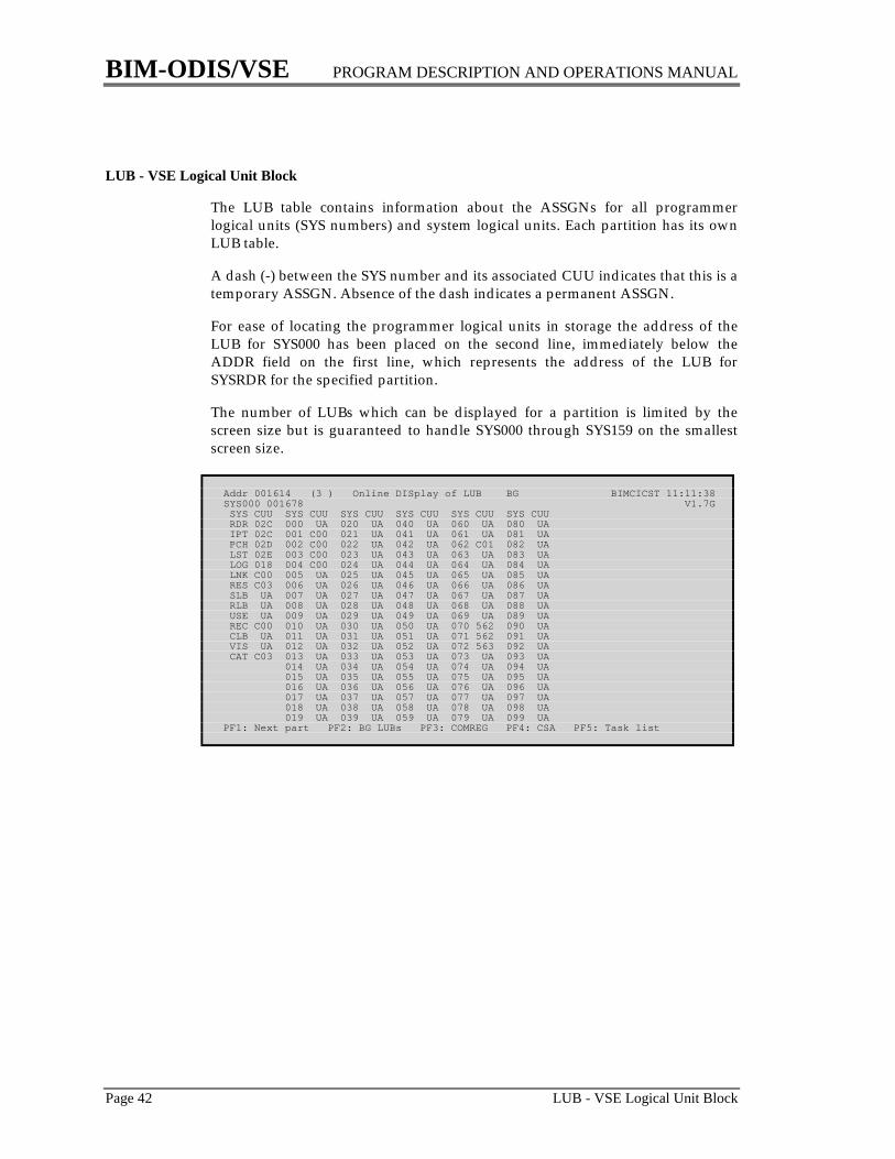
BIM-ODIS/VSE PROGRAM DESCRIPTION AND OPERATIONS MANUAL
Page 42 LUB - VSE Logical Unit Block
LUB - VSE Logical Unit Block
The LUB table contains information about the ASSGNs for all programmerlogical units (SYS numbers) and system logical units. Each partition has its ownLUB table.
A dash (-) between the SYS number and its associated CUU indicates that this is atemporary ASSGN. Absence of the dash indicates a permanent ASSGN.
For ease of locating the programmer logical units in storage the address of theLUB for SYS000 has been placed on the second line, immediately below theADDR field on the first line, which represents the address of the LUB forSYSRDR for the specified partition.
The number of LUBs which can be displayed for a partition is limited by thescreen size but is guaranteed to handle SYS000 through SYS159 on the smallestscreen size.
Addr 001614 (3 ) Online DISplay of LUB BG BIMCICST 11:11:38SYS000 001678 V1.7G SYS CUU SYS CUU SYS CUU SYS CUU SYS CUU SYS CUU RDR 02C 000 UA 020 UA 040 UA 060 UA 080 UA IPT 02C 001 C00 021 UA 041 UA 061 UA 081 UA PCH 02D 002 C00 022 UA 042 UA 062 C01 082 UA LST 02E 003 C00 023 UA 043 UA 063 UA 083 UA LOG 018 004 C00 024 UA 044 UA 064 UA 084 UA LNK C00 005 UA 025 UA 045 UA 065 UA 085 UA RES C03 006 UA 026 UA 046 UA 066 UA 086 UA SLB UA 007 UA 027 UA 047 UA 067 UA 087 UA RLB UA 008 UA 028 UA 048 UA 068 UA 088 UA USE UA 009 UA 029 UA 049 UA 069 UA 089 UA REC C00 010 UA 030 UA 050 UA 070 562 090 UA CLB UA 011 UA 031 UA 051 UA 071 562 091 UA VIS UA 012 UA 032 UA 052 UA 072 563 092 UA CAT C03 013 UA 033 UA 053 UA 073 UA 093 UA 014 UA 034 UA 054 UA 074 UA 094 UA 015 UA 035 UA 055 UA 075 UA 095 UA 016 UA 036 UA 056 UA 076 UA 096 UA 017 UA 037 UA 057 UA 077 UA 097 UA 018 UA 038 UA 058 UA 078 UA 098 UA 019 UA 039 UA 059 UA 079 UA 099 UAPF1: Next part PF2: BG LUBs PF3: COMREG PF4: CSA PF5: Task list
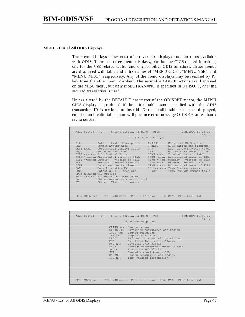
BIM-ODIS/VSE PROGRAM DESCRIPTION AND OPERATIONS MANUAL
MENU - List of All ODIS Displays Page 43
MENU - List of All ODIS Displays
The menu displays show most of the various displays and functions availablewith ODIS. There are three menu displays, one for the CICS-related functions,one for the VSE-related tables, and one for other ODIS functions. These menusare displayed with table and entry names of “MENU CICS”, “MENU VSE”, and“MENU MISC”, respectively. Any of the menu displays may be reached by PFkey from the other menu displays. The securable ODIS functions are displayedon the MISC menu, but only if SECTRAN=NO is specified in ODISOPT, or if thesecured transaction is used.
Unless altered by the DEFAULT parameter of the ODISOPT macro, the MENUCICS display is produced if the initial table name specified with the ODIStransaction ID is omitted or invalid. Once a valid table has been displayed,entering an invalid table name will produce error message ODIS019 rather than amenu screen.
Addr 000000 (3 ) Online DISplay of MENU CICS BIMCICST 11:14:19 V1.7G CICS Status Displays
AID Auto Initiate Descriptors SYSTEM Connected CICS systemsCSA Common System Area TABLES CICS tables and programsDEST xxxx Destination Control Table TAS List of active+susp tasksENQ Enqueued resources TAS * Abbreviated versn of taskFILE xxxxxxx File Control Table TERM xxxx Terminal Control TableFILE *xxxxxx Abbreviated versn of FILE TERM *xxxx Abbreviated versn of TERMFILE **xxxxx Summary version of FILE TERM **xxxx Summary version of TERMICE Interval Control Elements TRAN xxxx Program Control TableLINE Local and remote lines TRAN *xxxx Abbreviated versn of TRANPAM Page Allocation Map TS xxxxxxxx Temp Storage queuesPROB Potential CICS problems TSCOM Temp Storage common tablePROF xxxxxxx PCT profilePROG xxxxxxx Processing Program TableSR Shared Resources control blockSV Storage Violation summary
PF1: CICS menu PF2: VSE menu PF3: Misc menu PF4: CSA PF5: Task list
Addr 000000 (3 ) Online DISplay of MENU VSE BIMCICST 11:15:23 V1.7G VSE status displays
CHANQ xxx Channel queue COMREG xx Partition communications region LOCK xxx Locked resources LUB xx Logical Unit Blocks PART Information about all partitions PIB Partition Information Blocks PUB xxx Physical Unit Blocks SMCB Storage Management Control Blocks SPACE Space control blocks SVA Shared Virtual Area + SDL SYSCOM System communications region TID xx Task-related information
PF1: CICS menu PF2: VSE menu PF3: Misc menu PF4: CSA PF5: Task list

BIM-ODIS/VSE PROGRAM DESCRIPTION AND OPERATIONS MANUAL
Page 44 MENU - List of All ODIS Displays
Addr 000000 (3 ) Online DISplay of MENU MISC BIMCICST 11:16:09 V1.7G Miscellaneous displays CONSOL Current VSE console display DEMO Demonstrate most tables DLI DL/I SCD and BFPL PF Show the variable PF keys SCAN Scan storage in hex+char T=mmss Repeat display every mm:ss VBUF VTAM buffer pool usage WHO Identify this terminal xxxxxxxx 1-8 digit hexadecimal address +xxxxxxx 1-7 digit hexadecimal displacement
Securable features CP Issue VM CP commands POWER Issue POWER commands RESET UnDIAL your VM special terminal SEG Segment CICS SYSLST TRAK ON|OFF Start or stop ODISTRAK recording VTAM Issue VTAM commands WATCH MMSS|Off Start or stop The Watchdog
PF1: CICS menu PF2: VSE menu PF3: Misc menu PF4: CSA PF5: Task list

BIM-ODIS/VSE PROGRAM DESCRIPTION AND OPERATIONS MANUAL
PAM - CICS Page Allocation Map Page 45
PAM - CICS Page Allocation Map
The Page Allocation Map provides an overview of the Dynamic Storage Area.This is the area referred to at startup time by mesage DFH1500 - SUBPOOL SIZEIS nnnK. The DSA is divided into the subpools shown in the left hand column.The most important of these are:
TP used for TIOAsISO used for CLASS=LONG transactionsMIX used for CLASS=SHORT transactionsPGM used for non-resident programs
Examining these numbers will show how the DSA has been suballocated. Thenumber of pages allocated for PGM PAGES can (and probably should) beminimized by increasing the storage allocated to CICS and defining mostprograms as RES=YES in the PPT. The PROG display will show these (non-resident) programs as either RES=NO or RES=TEMP thus making it possible tosee exactly which non-resident programs are currently resident; the LENGTHfield of the PROB display will also show the exact size of each such program.
The dynamic storage allocated to CICS should be maintained at a high enoughlevel so that the field TOTAL REQ QUEUED is zero, the field PAGES B4 SOSdoes not reach zero, and CUSHION RELEASED field is zero. For a detaileddiscussion of CICS's use of storage and how the PAM display can be utilized seethe section “Using ODIS to Analyze Storage Utilization” starting on page 115.
The field FREE PAGES in DSA is calculated by ODIS. It is the PAGES IN DSAminus all of the XXX PAGES fields in the left hand column. This should be equalto the sum of CUSHION PAGES and PAGES B4 SOS.
The field labeled SCR ENTERED indicates how many storage violations haveoccurred. This is something which should never happen.
The field labeled MAX FREE AREA indicates the size of the largest contiguousarea of free storage. It represents the maximum amount of storage that atransaction can acquire in a single GETMAIN request.
The bottom portion of the PAM display is a map of the DSA. This is especiallyuseful for detecting storage fragmentation. Each character represents one page(usually 2048 bytes for VSE systems and 4096 for OS and VM systems) andcontains a value indicating which subpool owns the page:
C Control subpoolI Isolated subpoolK Transaction subpoolR RPL subpoolS Shared subpoolT TP subpool. unused

BIM-ODIS/VSE PROGRAM DESCRIPTION AND OPERATIONS MANUAL
Page 46 PAM - CICS Page Allocation Map
A lower case “p” is used for pages in the program subpool which Storage ControlProgram has indicated should be deleted when the program is no longer in use.This occurs when storage for the program subpool has been allocated below (i.e.at lower addresses than) storage used for one of the other subpools. Thiscondition will result in programs being fetched from the disk library morefrequently. While this will cause no problems to the CICS system, it would be agood idea to increase the size of the DSA if possible. If any of the pages in theDSA are deleted pages, the left hand side of the screen will show “Deleted PagesExist” as an additional reminder.
If the DSA map will not fit on the screen it is possible to display just the DSAmap by entering “PAM MAP”.
Addr ACFDF0 (3 ) Online DISplay of PAM BIMCICST 11:18:49 V1.7G00 CTL pages 3 70 Page size 2048 78 DSA Start 00AD100010 TP pages 1 74 Pages in DSA 1352 DSA end 00D74FFF 84 Cushion pages 49 7C Page map 1 00AD001030 TSK pages 26 88 Pages B4 SOS 468 Page map 2 00AD055840 SHR pages 107 Free pages 517 Max free area 1002K50 RPL pages 1 EC SCR entered 060 PGM pages 697 82 Curr req queued 0 Pages in use 835 Cushion released 0 High req queued 0 Totl req queued 0
Key to DSA subpool map: C=CTL K=TSK P=PGM p=Del PGM R=RPL S=SHR T=TP .=FreeCSTS.SKKSKKKKKKSSKSSSSSKSSSKSKKKSSSSSSSSSSSSSSSSSSKSSSSSSSSSSSSSSSSSSSSSSSSSSRSCKKKKSSSSSSSSSSSSSKKKKS.SSSS.SSS.S.SSSCSS.SS.S.SSSSSKKK.SSSS.......SSSSSSSS.....................................................................................................................................................................................................................................................................................................................................................................................................................................................................................................................PPPPPPPPPPPPPPPPPPPPPPPPPPPPPPPPPPPPPPPPPPPPPPPPPPPPPPPPPPPPPPPPPPPPPPPPPPPPPPPPPPPPPPPPPPPPPPPPPPPPPPPPPPPPPPPPPPPPPPPPPPPPPPPPPPPPPPPPPPPPPPPPPPPPPPPPPPPPPPPPPPPPPPPPPPPPPPPPPPPPPPPPPPPPPPPPPPPPPPPPPPPPPPPPPPPPPPPPPPPPPPPPP
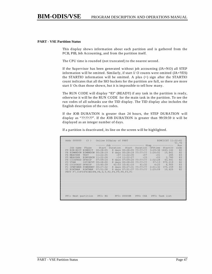
BIM-ODIS/VSE PROGRAM DESCRIPTION AND OPERATIONS MANUAL
PART - VSE Partition Status Page 47
PART - VSE Partition Status
This display shows information about each partition and is gathered from thePCB, PIB, Job Accounting, and from the partition itself.
The CPU time is rounded (not truncated) to the nearest second.
If the Supervisor has been generated without job accounting (JA=NO) all STEPinformation will be omitted. Similarly, if start I/O counts were omitted (JA=YES)the STARTIO information will be omitted. A plus (+) sign after the STARTIOcount indicates that all the SIO buckets for the partition are full, so there are morestart I/Os than those shown, but it is impossible to tell how many.
The RUN CODE will display “83” (READY) if any task in the partition is ready,otherwise it will be the RUN CODE for the main task in the partition. To see therun codes of all subtasks use the TID display. The TID display also includes theEnglish description of the run codes.
If the JOB DURATION is greater than 24 hours, the STEP DURATION willdisplay as “??:??:??”. If the JOB DURATION is greater than 99:59:59 it will bedisplayed as an integer number of days.
If a partition is deactivated, its line on the screen will be highlighted.
Addr 000000 (3 ) Online DISplay of PART BIMCICST 11:22:42 V1.7G ------ Job ------ --------------- Step -------------- Run Job name Phase Start Duration Start Duration CPUtime StartIO codeF9 BIM-EDIT BIMEDIT 00:28:05 8 days 00:28:05 ??:??:?? 3:29:38 1443,142 82F8 BIMWNDOW BIMWNDOW 00:28:19 8 days 00:28:18 ??:??:?? 1:26:02 15,861 82F6 MEAVSHR TEST 11:22:35 :07 11:22:35 :07 :01 285 83F5 MEAVSHR BIMVSBCM 11:22:28 :14 11:22:27 :15 :03 2,780 83F4 CICSPROD DFHSIP 07:09:14 8 days 07:09:20 ??:??:?? 1:32:28 43,541 82F3 VTAM ISTINCVT 00:28:00 8 days 00:28:00 ??:??:?? 57:13 970,219 82F2 CICSTEST DFHSIP 10:40:39 42:03 10:41:10 41:32 4:25 8,905 83F1 IPWPOWER POWERNET 00:27:32 8 days 00:27:31 ??:??:?? 2:01:32 375,159 82Y1 BIMTMAN BIMTMAN 07:51:38 8 days 07:51:37 ??:??:?? 1:25:09 10,625 82PRTY F7,C=F5=F6=BG=FB,FA,G,Y,F2,F4,F9,F8,F3,F1
PF1: Next partition PF2: BG PF3: SYSCOM PF4: CSA PF5: Task list
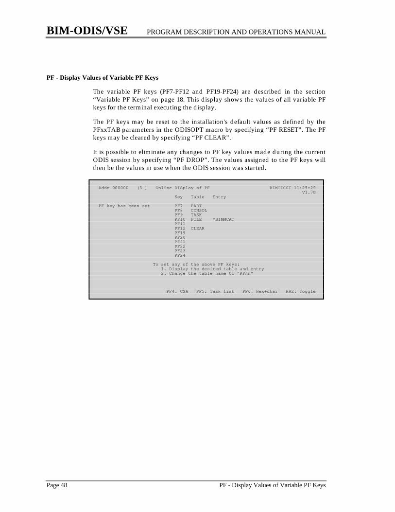
BIM-ODIS/VSE PROGRAM DESCRIPTION AND OPERATIONS MANUAL
Page 48 PF - Display Values of Variable PF Keys
PF - Display Values of Variable PF Keys
The variable PF keys (PF7-PF12 and PF19-PF24) are described in the section“Variable PF Keys” on page 18. This display shows the values of all variable PFkeys for the terminal executing the display.
The PF keys may be reset to the installation's default values as defined by thePFxxTAB parameters in the ODISOPT macro by specifying “PF RESET”. The PFkeys may be cleared by specifying “PF CLEAR”.
It is possible to eliminate any changes to PF key values made during the currentODIS session by specifying “PF DROP”. The values assigned to the PF keys willthen be the values in use when the ODIS session was started.
Addr 000000 (3 ) Online DISplay of PF BIMCICST 11:25:29 V1.7G Key Table Entry
PF key has been set PF7 PART PF8 CONSOL PF9 TASK PF10 FILE *BIMMCAT PF11 PF12 CLEAR PF19 PF20 PF21 PF22 PF23 PF24
To set any of the above PF keys: 1. Display the desired table and entry 2. Change the table name to "PFnn"
PF4: CSA PF5: Task list PF6: Hex+char PA2: Toggle

BIM-ODIS/VSE PROGRAM DESCRIPTION AND OPERATIONS MANUAL
PIB ----- VSE Partition Information Block Page 49
PIB - VSE Partition Information Block
The PIB and PIB extension (or PIB2) contain information about each partition.
The SYS LUBS field includes the fourteen standard system logical units plusadditional logical units for LIBDEF processing.
The MODE column indicates whether a partition is currently running in VIRTualor REAL mode.
Addr 001528 (3 ) Online DISplay of PIB BIMCICST 11:44:01PIB2 001458 V1.7G
------------------ PIB ----------------- ---------- PIB2 ---------- Orig Sys Prog Flag stat ID V part LUBs LUBs Mode COMREG TID PCB PIK
80 00 AR 000000 50 30 Virt 003CA0 0020 041BC0 0000 00 82 BG 600000 50 100 Virt 0005B8 0021 043240 0010 00 00 FB 800000 50 100 Virt 0049B0 002C 043060 0020 00 00 FA A00000 50 100 Virt 004880 002B 042E80 0030 00 00 F9 800000 50 100 Virt 004750 002A 042CA0 0040 00 00 F8 600000 50 100 Virt 004620 0029 042AC0 0050 00 00 F7 C00000 50 100 Virt 0044F0 0028 0428E0 0060 00 82 F6 800000 50 100 Virt 0043C0 0027 042700 0070 00 82 F5 600000 50 100 Virt 004290 0026 042520 0080 00 00 F4 C00000 50 100 Virt 004160 0025 042340 0090 00 00 F3 600000 50 100 Virt 004030 0024 042160 00A0 00 83 F2 A00000 50 100 Virt 003F00 0023 041F80 00B0 00 00 F1 600000 50 100 Virt 003DD0 0022 041DA0 00C0 00 00 Y1 620000 50 100 Virt 430520 002D 430088 00D0 00 00 G1 620000 50 100 Virt 42B520 002E 42B088 00E0 ++++ (More Partitions) ++++ PF3: SYSCOM PF4: CSA PF5: Task list PF6: Hex+char PA2: Toggle

BIM-ODIS/VSE PROGRAM DESCRIPTION AND OPERATIONS MANUAL
Page 50 POWER - Issue POWER Commands
POWER - Issue POWER Commands
This is not a display of any table. It provides the ability to issue commands toPOWER from a CICS terminal. Because of the potential consequences of thiscommand its use may be restricted by specifying a SECTRAN in the ODISOPTmacro.
When initially starting ODIS the POWER command may follow the keywordPOWER (e.g. ODIS POWER A RDR,ABCJOB,PRI=4). Subsequently, use of thisfacility is a two step procedure. After entering POWER as the table name a screenwill be returned with room to enter a POWER command on the third line. Afterfilling in the appropriate command and hitting the enter key ODIS will pass thecommand to POWER and display POWER's response (which is limited to oneline).
The LOGPOW parameter of the ODISOPT macro may be used to instruct ODISto log all POWER commands to the VSE console or to a Transient Datadestination.
This facility uses the CTLSPOOL facility of POWER which will not allow certaincommands to be executed. These include PGO (G), PFLUSH (F), PSTART (S),PSTOP (P) and PEND.
Addr 000000 (3 ) Online DISplay of POWER BIMCICST 11:48:03 V1.7GEnter command: A LST,BIMASSEM,CLASS=A,DISP=D
POWER Response: 1R88I OK
PF3: SYSCOM PF4: CSA PF5: Task list PF6: Hex+char PA2: Toggle
BIM-ODIS/VSE PROGRAM DESCRIPTION AND OPERATIONS MANUAL
PROB - Potential CICS Problems Page 51
PROB - Potential CICS Problems
This display is designed to collect in one place many of the various potentialproblems in CICS. The column labeled IMPACTS contains one of the followingvalues:
SYSTEM indicates that the problem is capable of affecting nearly everytask in the system, for example being Short On Storage (virtual).
TASKS indicates that the problem will probably affect only some of thetasks in the system, for example a VSAM file's strings all being inuse.
The SEV column on the PROB display gives a rough indication of how severe theproblem may be. It will be HIGH, MED, LOW or NOTE. NOTE is used toindicate past problems which have been dealt with. The TABLE column gives anindication of another ODIS display which gives more information about theproblem.
ODIS checks for the potential problems listed below. The number before eachdescription matches the NUM column on the PROB display and may be used toprevent some of these messages from being reported by The Watchdog. (They arealways reported on the PROB display.) Also, the severity assigned to eachmessage is shown. Messages may also be suppressed categorically by severitylevel. Message suppression is accomplished by using the WATSUPR parameterof the ODISOPT macro or the ENABLE and DISABL functions. The ODISOPTmacro also contains a number of user-defined thresholds which determine whensome of these problems are to be reported by ODIS. See the THxxxxx parametersof the ODISOPT macro on page 11.
1. Short On (Virtual) Storage (Severity: HIGH)The CICS system is currently Short On Storage. For a more detaileddiscussion of this problem see the section “Using ODIS to Analyze StorageUtilization” starting on page 115.
2. Approaching Short On (Virtual) Storage (Severity: LOW)The number of unused pages in the DSA (in addition to the storage cushion)is below the threshold specified by the THASOS parameter of the ODISOPTmacro; the default is 25 pages. This does not represent an actual problem butdoes indicate that the CICS system may soon be Short On Storage. For a moredetailed discussion of this problem see the section “Using ODIS to AnalyzeStorage Utilization” starting on page 115.
3. Short On (Virtual) Storage Has Occurred (Severity: NOTE)The CICS system has been Short On Storage but is not currently Short OnStorage (unless problem number 1 is also reported.) While this may not havecaused any serious problems, steps should be taken to prevent this conditionin the future. For a more detailed discussion of this problem see the section“Using ODIS to Analyze Storage Utilization” starting on page 115.
4. Storage Violations Have Occurred (Severity: NOTE)

BIM-ODIS/VSE PROGRAM DESCRIPTION AND OPERATIONS MANUAL
Page 52 PROB - Potential CICS Problems
CICS has detected and recovered from one or more storage violations.Because these are potentially severe they should be diagnosed and resolvedas quickly as possible. For a more detailed discussion of this problem see thesection “Using ODIS to Analyze Storage Utilization” starting on page 115.
5. Runaway Tasks Have Occurred (Severity: NOTE)CICS has detected and cancelled one or more runaway tasks. These do notcause any particular problems to the CICS system except for a mysterious,but temporary, increase in response for all tasks.
6. Maximum Task Limit (Severity: MED)The CICS system is currently at the maximum task limit. CICS will not allowany new transactions to be started until some existing transactions end. Thiscondition should generally be avoided by setting the MXT value in the SIT toa number which will never be reached.
7. Approaching Maximum Task Limit (Severity: LOW)The number of active and suspended tasks in the CICS system exceeds apercentage of the maximum task limit. This percentage is specified by theTHAMAX parameter of the ODISOPT macro; the default is 75%.
8. Maximum Active Task Limit (Severity: MED)The CICS system is currently at the maximum active task limit. Generally,this will slow down some transactions in the system but will not preventthem from executing.
9. Approaching Maximum Active Task Limit (Severity: LOW)The number of active tasks in the CICS system exceeds a percentage of themaximum active task limit. This percentage is specified by the THAAMAXparameter of the ODISOPT macro; the default is 75%
10. Runaway Task Control is Turned Off (Severity: NOTE)This will not cause a problem unless a runaway task occurs in which caseCICS will not be able to terminate the runaway task, and it may be necessaryto cancel CICS.
11. Auxiliary Temporary Storage Has Been Exhausted (Severity: NOTE)The DFHTEMP data set has been filled at least once. It should be enlarged.
12. Tasks Waiting For (Virtual) Storage (Severity: HIGH)One or more tasks have issued unconditional GETMAIN requests whichcannot be satisfied. This will probably occur at the same time as problemnumber 1.
13. DL/I Maximum Task Limit (Severity: HIGH)The number of DL/I transactions has reached the DL/I MAXTASK limit(which is initially specified in the DL/I ACT, not in the CICS SIT). DL/I willnot allow any additional transactions to issue SCHEDULE commands.
14. DL/I Current Maximum Task Limit (Severity: HIGH)The number of DL/I transactions has reached the DL/I CMAXTSK limit(which is initially specified in the DL/I ACT, not in the CICS SIT). DL/I willnot allow any additional transactions to issue SCHEDULE commands.
BIM-ODIS/VSE PROGRAM DESCRIPTION AND OPERATIONS MANUAL
PROB - Potential CICS Problems Page 53
15. Tasks Waiting For Enqueued Resources (Severity: HIGH)One or more tasks are waiting for access to user-defined or CICS-definedresources. Generally, this should be a temporary condition; when theowner(s) of the resource(s) issues a DEQ the first waiting task will be givenaccess to the resource. This problem is recognized only if the number ofwaiting tasks exceeds the value specified by the THWENQ parameter of theODISOPT macro; the default is zero.
16. Tasks Have Been Stall Purged (Severity: NOTE)CICS has been Short On Storage for the length of time specified by stallinterval and has canceled one or more transactions. This condition should beavoided. For a more detailed discussion of this problem see the section“Using ODIS to Analyze Storage Utilization” starting on page 115.
17. Transaction Running at a Terminal Which is Out of Service (Severity: HIGH)A transaction is running at a terminal which is out of service, not connectedto VTAM, or whose line or control unit is out of service. This can happenonly if an error occurs after the transaction has been started. The transactionwill not be serviced by CICS until the condition is corrected.
18. Transaction Using Too Much Storage (Severity: LOW)A transaction is using more storage than the value specified by the THSTORparameter of the ODISOPT macro; the default is 24K. This will impact theCICS system only if the storage cushion is reached; however, it is advisableto examine the program to see if it is wasting storage or failing to free storagethat it no longer needs. In some cases it may be impractical or impossible tochange the program(s) involved. In fact, the transaction may work well withthe relatively large amount of storage. In this case, the installation shouldinsure that the DSA contains enough storage to support the transaction,particularly if it is a frequently used, true conversational transaction.
19. Tasks Waiting for Class Maximum Task Limits (Severity: HIGH)One or more transactions are unable to execute because their associatedtransaction class is at its limit. Other transactions are totally unaffected. Sincethese limits are established by the installation this condition is probablyintentional. This condition will be recognized only if the number of waitingtasks exceeds the value specified by the THWCMAX parameter specified inthe ODISOPT macro; the default is zero.
20. (Removed for CICS 1.7.)
21. Tasks Waiting For VSAM Strings (Severity: HIGH)One or more transactions are waiting for a VSAM string. This condition willbe recognized only if the number of waiting tasks for one file exceeds thevalue specified by the THWSTR parameter specified in the ODISOPT macro;the default is zero. For a more detailed discussion see the section “UsingODIS to Tune VSAM Files” starting on page 123.
22. Tasks Waiting For VSAM Buffers (Severity: HIGH)One or more transactions are waiting for a VSAM buffer. This condition willbe recognized only if the number of waiting tasks for one file exceeds thevalue specified by the THWBUFF parameter specified in the ODISOPT
BIM-ODIS/VSE PROGRAM DESCRIPTION AND OPERATIONS MANUAL
Page 54 PROB - Potential CICS Problems
macro; the default is zero. For a more detailed discussion see the section“Using ODIS to Tune VSAM Files” starting on page 123.
23. Largest Contiguous Free Area in DSA is Too Small (Severity: LOW)The largest contiguous free area in the DSA is less than the value specified bythe THFREE parameter of the ODISOPT macro. This is the largest amount ofstorage currently available for a GETMAIN or for loading a non-residentprogram. There is no immediate problem, however. For a more detaileddiscussion of this problem see the section “Using ODIS to Analyze StorageUtilization” starting on page 115.
24. Auxiliary Temporary Storage is Near Capacity (Severity: LOW)The percentage of the DFHTEMP data set which is in use exceeds the valuespecified by the THAUXTS parameter of the ODISOPT macro; the default is90%.
25. Too Many Control Area Splits (Severity: NOTE)The number of CA splits for a file exceeds the value specified by THCASPLparameter of the ODISOPT macro; the default is 1. For a more detaileddiscussion see the section “Using ODIS to Tune VSAM Files” starting onpage 123.
26. Too Many Control Interval Splits (Severity: NOTE)The number of CI splits for a file exceeds the value specified by THCISPLparameter of the ODISOPT macro; the default is 5. For a more detaileddiscussion see the section “Using ODIS to Tune VSAM Files” starting onpage 123.
27. VTAM ACB Is Closed (Severity: MED)The VTAM ACB is closed. CICS cannot access any of its VTAM terminalswhile CICS'S VTAM ACB is closed.
28. VTAM Has Been Temporarily Short On Storage (Severity: NOTE)The number of VTAM requests issued by CICS which have been rejected byVTAM due to a temporary short on storage condition in VTAM exceeds thevalue specified by the THVSOS parameter of the ODISOPT macro; thedefault is 3.
29. Non-resident Programs Have Been Fetched Too Many Times (Severity:NOTE)Since CICS records the number of times the system has been Short OnStorage but not the number of times the storage cushion has been reachedthis is an attempt to estimate this latter number. It indicates that one or morereusable (RELOAD=NO), non-resident (RES=NO) programs (not maps) havebeen fetched more times than the value specified by the THFETCHparameter of the ODISOPT macro; the default is 3. This indicates thatprograms may be being fetched too many times. This is an attempt to detectthe situation where a small DSA forces CICS to release the non-residentprograms many times each day causing an excessive number of fetches;however, the fetch count can also be increased by issuing several CSMTNEWCOPYs for a program, in which case this message must not beconstrued to mean that the DSA is too small. The number of program fetches
BIM-ODIS/VSE PROGRAM DESCRIPTION AND OPERATIONS MANUAL
PROB - Potential CICS Problems Page 55
may be reduced by making more programs resident or by increasing the sizeof the DSA, but both of these options require more virtual storage. This maybe a minor inefficiency but does not cause any problems. For a more detaileddiscussion of this problem see the section “Using ODIS to Analyze StorageUtilization” starting on page 115.
In addition to the above problems, The Watchdog is able to detect the occurrenceof the following events during the time interval between executions of TheWatchdog.
60. Delay in Initiating The WatchdogAfter the time interval used by The Watchdog expired, The Watchdog wasnot invoked until after another time interval, specified by the THDELAYparameter of the ODISOPT macro, expired; the default is one minute. This isa broad indicator and may be caused by a number of factors such as:a. the operator stopping the CPUb. CICS not being dispatched due to other higher priority
partitions/regionsc. CICS conditions such as maximum task limits, Short On Storage storage
violation dumps, etc.d. the WATTERM terminal being used by another transaction
61. Storage ViolationA storage violation has been detected, and CICS has recovered successfully.For a more detailed discussion of this problem see the section “Using ODIS toAnalyze Storage Utilization” starting on page 115.
62. Short On (Virtual) StorageThe CICS system was SOS but is not currently SOS (unless problem 1 is alsoreported). For a more detailed discussion of this problem see the section“Using ODIS to Analyze Storage Utilization” starting on page 115.
63. Maximum Task LimitThe CICS system was at the maximum task limit but is now below the limit(unless problem 6 is also reported).
Miscellaneous Notes
1. The IMPACTS and SEV columns are somewhat subjective and should betreated as such.
2. This display is not capable of detecting every possible error situation.
3. Some of the conditions detected on this display may not, in fact, be errors, forexample tasks waiting for enqueued resources. This display shows potentialproblems as well as guaranteed problems.
4. This display is limited to one screen.
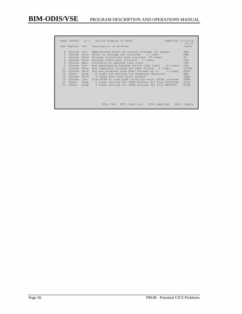
BIM-ODIS/VSE PROGRAM DESCRIPTION AND OPERATIONS MANUAL
Page 56 PROB - Potential CICS Problems
Addr 000000 (3 ) Online DISplay of PROB BIMCICST 12:14:16 V1.7GNum Impacts Sev Description of problem Table
2 System Low Approaching short on virtual storage (21 pages) PAM 3 System Note Short on storage has occurred 2 times PAM 4 System Note Storage violations have occurred 20 times SV 5 System Note Runaway tasks have occurred 3 times CSA 6 System Med Currently at maximum task limit CSA 9 System Low Now approaching maximum active task limit (4 tasks) CSA 11 System Note Aux temporary storage has been filled 4 times TSCOM 29 System Note Non-res programs have been fetched up to 9 times PROG 15 Tasks High 8 tasks are waiting for enqueued resources ENQ 16 System Note 9 tasks have been stall purged TRAN 18 System Low Tran BIGM at term QQ4B using too much (280k) storage TERM 22 Tasks High 1 tasks waiting for VSAM buffers for file CUSTFILE FILE 21 Tasks High 3 tasks waiting for VSAM strings for file MASTFIL FILE
PF4: CSA PF5: Task list PF6: Hex+Char PA2: Toggle
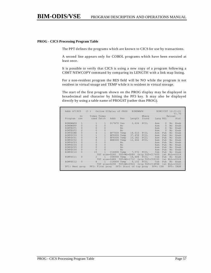
BIM-ODIS/VSE PROGRAM DESCRIPTION AND OPERATIONS MANUAL
PROG - CICS Processing Program Table Page 57
PROG - CICS Processing Program Table
The PPT defines the programs which are known to CICS for use by transactions.
A second line appears only for COBOL programs which have been executed atleast once.
It is possible to verify that CICS is using a new copy of a program following aCSMT NEWCOPY command by comparing its LENGTH with a link map listing.
For a non-resident program the RES field will be NO while the program is notresident in virtual stoage and TEMP while it is resident in virtual storage.
The start of the first program shown on the PROG display may be displayed inhexadecimal and character by hitting the PF3 key. It may also be displayeddirectly by using a table name of PROGST (rather than PROG).
Addr A719C0 (3 ) Online DISplay of PROG BIMSWAPX BIMCICST 12:31:21 V1.7G In Times Times Where ReloadProgram use used fetch Addr Res Length found Lang RSL Stat
BIMSWAPX 1 1 1 D17A70 Yes 2,634 PCIL Asm 0 No EnabBIMSWSFP 0 0 0 No Asm 0 No EnabBIMTEST1 0 0 0 No Asm 0 No EnabBIMTEST2 0 0 0 No Asm 0 No EnabBIMVSCMO 0 4 1 BF7008 Temp 18,610 PCIL Asm Pub No EnabBIMVSC00 0 1 1 BFD808 Temp 37,458 PCIL Asm Pub No EnabBIMVSC01 0 4 1 BF4008 Temp 10,362 PCIL Asm Pub No EnabBIMVSC02 0 8 1 BEE008 Temp 12,466 PCIL Asm Pub No EnabBIMVSC03 0 0 0 No Asm Pub No EnabBIMVSC04 0 0 0 No Asm Pub No EnabBIMVSC05 0 0 0 No Asm Pub No EnabBIMVSC06 0 0 0 No Asm Pub No EnabBIMVSC10 0 15 1 C16808 Temp 7,572 PCIL Cob Pub No Enab TGT size=0280 TGT+WS=0D84 Orig TGT=C17400 1st BLL=+0224BIMVSC11 0 2 1 C08008 Temp 16,608 PCIL Cob Pub No Enab TGT size=04E8 TGT+WS=171C Orig TGT=C09330 1st BLL=+0324BIMVSC12 0 8 1 C14808 Temp 6,152 PCIL Cob Pub No Enab TGT size=0298 TGT+WS=0924 Orig TGT=C14F88 1st BLL=+022CPF1: Next prog PF2: First prog PF3: Start of top prog PF4: CSA PF5: TASK
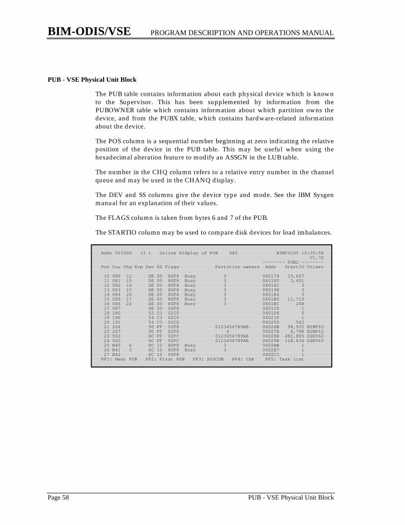
BIM-ODIS/VSE PROGRAM DESCRIPTION AND OPERATIONS MANUAL
Page 58 PUB - VSE Physical Unit Block
PUB - VSE Physical Unit Block
The PUB table contains information about each physical device which is knownto the Supervisor. This has been supplemented by information from thePUBOWNER table which contains information about which partition owns thedevice, and from the PUBX table, which contains hardware-related informationabout the device.
The POS column is a sequential number beginning at zero indicating the relativeposition of the device in the PUB table. This may be useful when using thehexadecimal alteration feature to modify an ASSGN in the LUB table.
The number in the CHQ column refers to a relative entry number in the channelqueue and may be used in the CHANQ display.
The DEV and SS columns give the device type and mode. See the IBM Sysgenmanual for an explanation of their values.
The FLAGS column is taken from bytes 6 and 7 of the PUB.
The STARTIO column may be used to compare disk devices for load imbalances.
Addr 003300 (3 ) Online DISplay of PUB 080 BIMCICST 12:35:58 V1.7G -------- PUB2 --------Pos Cuu Chq Erp Dev SS Flags Partition owners Addr StartIO Volser
10 080 12 DE 00 80F8 Busy 3 060174 15,657 11 081 10 DE 00 80F8 Busy 3 060180 3,651 12 082 14 DE 00 80F8 Busy 3 06018C 3 13 083 15 DE 00 80F8 Busy 3 060198 3 14 084 20 DE 00 80F8 Busy 3 0601A4 3 15 085 17 DE 00 80F8 Busy 3 0601B0 11,719 16 086 22 DE 00 80F8 Busy 3 0601BC 268 17 087 DE 00 00F8 0601C8 1 18 180 52 C3 02C0 0601D4 0 19 190 54 C3 02C0 060230 1 20 191 54 C3 02C0 060250 562 21 266 90 FF 02F8 0123456789AB 06026B 98,935 BIMVIO 22 267 90 FF 02F8 4 06027B 6,798 BIMVI2 23 562 6C FF 02FC 0123456789AB 06028B 482,805 DSK562 24 563 6C FF 02FC 0123456789AB 06029B 128,836 DSK563 25 B40 6 DC 10 80F8 Busy 3 0602AB 1 26 B41 3 DC 10 80F8 Busy 3 0602B7 1 27 B42 DC 10 00F8 0602C3 1PF1: Next PUB PF2: First PUB PF3: SYSCOM PF4: CSA PF5: Task list
BIM-ODIS/VSE PROGRAM DESCRIPTION AND OPERATIONS MANUAL
RESET - Reset Terminal Under VM Page 59
RESET - Reset Terminal Under VM
This is not a display of any table. It provides the ability to issue the CP RESETcommand for any CICS terminal running under VM. The purpose of this featureis to allow a VM “special” terminal to disconnect itself from its virtual machineand return control to CP. It provides the inverse of the CP DIAL command. Theterminal that is reset is the terminal issuing the ODIS RESET command. To reseta different terminal issue the ODIS CP command. The RESET feature is notsecured.
For local BTAM 3270 terminals ODIS is able to determine the correct virtualdevice address to be reset. Other terminals may be reset if they are specified in anODISOPT macro as described in the section “ODISOPT Macro” on page 7.
After successfully resetting the terminal the operator will be signed off theterminal just as if a “CSSF” transaction had been entered. This may besuppressed by specifying RESET KEEP.

BIM-ODIS/VSE PROGRAM DESCRIPTION AND OPERATIONS MANUAL
Page 60 SCAN - Scan Storage
SCAN - Scan Storage
The scan facility provides the ability to scan storage, in hexadecimal or character,looking for a specific character string. Use of this facility is a two step procedure.After entering SCAN as the table name and hitting ENTER, a screen will bereturned showing the hexadecimal and character information most recentlydisplayed, if any. Entry fields are provided for a new scan argument and methodof search.
The “Format” field is used to specify whether the scan data argument is incharacter (c) or hexadecimal (h or x) format. The “Case” field indicates themanner in which ODIS compares the storage being scanned and the scanargument.
1. U (upper) indicates that the supplied scan data is to be translated to uppercase. ODIS will look for an exact match on this string.
2. M (mixed) indicates that the supplied scan data is to be accepted “as is”. Itmay contain any combination of upper and lower case characters. ODIS willlook for an exact match on this string.
3. I (ignore) indicates that ODIS is to look for a match by ignoring thedistinction between upper and lower case characters. For example,} the string“banana” would be matched by “banana”, “BANANA”, and “BaNaNa”.
The scan data may contain up to 64 characters or hexadecimal digits. ODIS willbegin with the first address on the screen (plus one), in the “Current AddressSpace”, and scan for the first occurrence of the specified data. Upon encounteringthe data ODIS will display the area containing the data. The scan may berepeated by hitting the enter key again. For more information on “CurrentAddress Space”, refer to page 93.
During the scan ODIS will display its progress after processing each 64K bytes ofstorage. It will scan the entire machine if necessary and will skip over any invalidaddress spaces.
A scan will be terminated when one of the following conditions occurs:
1. The string is found2. The highest virtual storage address of the machine is reached3. The end of the CICS partition/region is reached4. The operator hits the clear key on a non-SNA terminal5. The operator hits the ATTN key on an SNA terminal6. A megabyte boundary is reached while scanning above the 16MB boundary
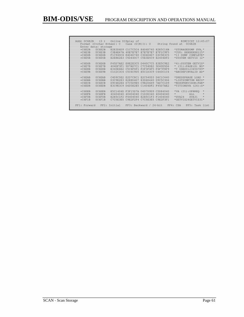
BIM-ODIS/VSE PROGRAM DESCRIPTION AND OPERATIONS MANUAL
SCAN - Scan Storage Page 61
Addr 0C6E2B (3 ) Online DISplay of BIMCICST 12:45:07 Format (C=char H=hex): C Case (U|M|I): U String found at 0C6E2B Enter data: storage +C6E2B 0C6E2B E2E3D6D9 C1C7C5C4 E4D4D740 E2E5C16B *STORAGEDUMP SVA,* +C6E3B 0C6E3B C3E4E47A 40E7E7E7 E7E7E7E7 E7F1C9F5 *CUU: XXXXXXXX1I5* +C6E4B 0C6E4B F1C940C4 E4D4D740 C3D6D4D7 D3C5E3C5 *1I DUMP COMPLETE* +C6E5B 0C6E5B E2E8E2E3 C5D440C7 C5E3E5C9 E2404DF2 *SYSTEM GETVIS (2*
+C6E6B 0C6E6B F45D7AE2 E8E2E3C5 D440C7C5 E3E5C9E2 *4):SYSTEM GETVIS* +C6E7B 0C6E7B 404DF3F1 5D7AD7C1 C7C54DE2 5D40D5D6 * (31):PAGE(S) NO* +C6E8B 0C6E8B E340E4E2 C5C4F0F1 F2F3F4F5 F6F7F8F9 *T USED0123456789* +C6E9B 0C6E9B C1C2C3C4 C5C6C9D5 E5C1D3C9 C440C1C4 *ABCDEFINVALID AD*
+C6EAB 0C6EAB C4D9C5E2 E2D7C8C1 E2C540D3 D6C1C440 *DRESSPHASE LOAD * +C6EBB 0C6EBB D3C9E2E3 E2E8D4D7 E3D6D440 D9C5C3D6 *LISTSYMPTOM RECO* +C6ECB 0C6ECB D9C4E2E4 D7C5D9E5 C9E2D6D9 7AD7C1D9 *RDSUPERVISOR:PAR* +C6EDB 0C6EDB E3C9E3C9 D6D5E2E5 C1404DF2 F45D7AE2 *TITIONSVA (24):S*
+C6EEB 0C6EEB E5C1404D F3F15D7A D6D7D9D9 C5D84040 *VA (31):OPRREQ * +C6EFB 0C6EFB 40404040 40404040 C1D3D340 40404040 * ALL * +C6F0B 0C6F0B E2E5C1F2 F4404040 E2E5C1F3 F1404040 *SVA24 SVA31 * +C6F1B 0C6F1B C7C5E3E5 C9E2F2F4 C7C5E3E5 C9E2F3F1 *GETVIS24GETVIS31*
PF1: Forward PF2: Initial PF3: Backward / 24-bit PF4: CSA PF5: Task list

BIM-ODIS/VSE PROGRAM DESCRIPTION AND OPERATIONS MANUAL
Page 62 SEG - Segment CICS Printed Output
SEG - Segment CICS Printed Output
This is not a display of any table. It provides the ability to segment the printedoutput from CICS, thus placing it in POWER LST queue where it may be printedand examined immediately without being required to shut down CICS. Becauseof the disruptive effect this may have on CICS reports its use may be restricted byspecifying a SECTRAN in the ODISOPT macro.
The “entry” name may be LST (to segment SYSLST) or a 1-3 digit decimalnumber (to segment SYSNNN). The default is SYSLST.
This feature uses the SEGMENT macro. The LST card associated with it isspecified by the JECL parameter in the ODISOPT macro. This will apply to theoutput created after the SEGMENT is issued, not to the output alreadyaccumulated.
Addr 000000 (3 ) Online DISplay of SEG LST BIMCICST 12:47:31 V1.7GSEGMENT macro has been issued RC=X'00'* $$ LST CLASS=A,DISP=D
PF3: SYSCOM PF4: CSA PF5: Task list PF6: Hex+char PA2: Toggle
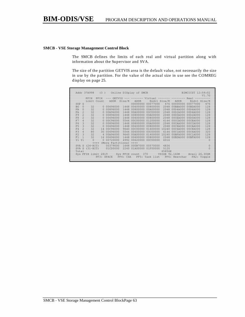
BIM-ODIS/VSE PROGRAM DESCRIPTION AND OPERATIONS MANUAL
SMCB - VSE Storage Management Control BlockPage 63
SMCB - VSE Storage Management Control Block
The SMCB defines the limits of each real and virtual partition along withinformation about the Supervisor and SVA.
The size of the partition GETVIS area is the default value, not necessarily the sizein use by the partition. For the value of the actual size in use see the COMREGdisplay on page 25.
Addr 37A998 (3 ) Online DISplay of SMCB BIMCICST 12:59:02 V1.7G PFIX PFIX --- GETVIS --- ------- Virtual ------- -------- Real --------- Limit Count ADDR Size/K ADDR End+1 Size/K ADDR End+1 Size/KSUP S 00000000 00077000 476 00000000 00077000 476BG 0 32 0 00696000 1448 00600000 00800000 2048 00BBA000 00BDA000 128FB 0 32 0 00896000 1448 00800000 00A00000 2048 00D4A000 00D6A000 128FA 2 32 0 00A96000 1448 00A00000 00C00000 2048 00D2A000 00D4A000 128F9 2 32 0 00896000 1448 00800000 00A00000 2048 00D0A000 00D2A000 128F8 2 32 0 00696000 1448 00600000 00800000 2048 00CEA000 00D0A000 128F7 4 32 0 00C96000 5544 00C00000 01200000 6144 00CCA000 00CEA000 128F6 3 32 0 00896000 1448 00800000 00A00000 2048 00CAA000 00CCA000 128F5 3 32 0 00696000 1448 00600000 00800000 2048 00C8A000 00CAA000 128F4 2 32 14 00C96000 9640 00C00000 01600000 10240 00C6A000 00C8A000 128F3 4 80 30 00696000 5544 00600000 00C00000 6144 00C1A000 00C6A000 320F2 3 32 4 00A96000 9640 00A00000 01400000 10240 00BFA000 00C1A000 128F1 1 32 16 00696000 1448 00600000 00800000 2048 00BDA000 00BFA000 128Y1 Y1 0 0 00720000 4992 00620000 00C00000 6016 0 ++++ (More Partitions) ++++SVA S (24-BIT) 00379000 1648 000B7000 00570000 4836 0SVA S (31-BIT) 01CD0000 2240 01A00000 01F00000 5120 0Total 65856KSys PFIX limit 2819 Sys PFIX count 370 VSIZE 92,160K Avail 26,304K PF3: SPACE PF4: CSA PF5: Task list PF6: Hex+char PA2: Toggle
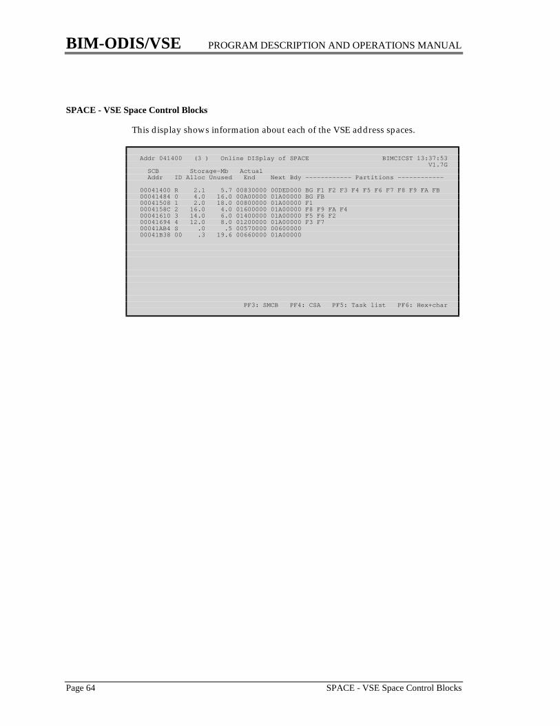
BIM-ODIS/VSE PROGRAM DESCRIPTION AND OPERATIONS MANUAL
Page 64 SPACE - VSE Space Control Blocks
SPACE - VSE Space Control Blocks
This display shows information about each of the VSE address spaces.
Addr 041400 (3 ) Online DISplay of SPACE BIMCICST 13:37:53 V1.7G SCB Storage-Mb Actual Addr ID Alloc Unused End Next Bdy ------------ Partitions ------------
00041400 R 2.1 5.7 00830000 00DED000 BG F1 F2 F3 F4 F5 F6 F7 F8 F9 FA FB00041484 0 4.0 16.0 00A00000 01A00000 BG FB00041508 1 2.0 18.0 00800000 01A00000 F10004158C 2 16.0 4.0 01600000 01A00000 F8 F9 FA F400041610 3 14.0 6.0 01400000 01A00000 F5 F6 F200041694 4 12.0 8.0 01200000 01A00000 F3 F700041AB4 S .0 .5 00570000 0060000000041B38 00 .3 19.6 00660000 01A00000
PF3: SMCB PF4: CSA PF5: Task list PF6: Hex+char

BIM-ODIS/VSE PROGRAM DESCRIPTION AND OPERATIONS MANUAL
SR - CICS Shared Resources Control Block Page 65
SR - CICS Shared Resources Control Block
The Shared Resources Control Block contains information used to manage theuse of VSAM Shared Resources for those files which are defined in the FCT withSERVREQ=SHARE. The major resources which are shared are strings andbuffers. For more information on Shared Resources see the section “Using ODISto Tune VSAM Files” starting on page 123.
Addr A7B1D8 (3 ) Online DISplay of SR BIMCICST 13:41:40 V1.7G18 Percentile 50 Buffer Total2C Max key length 128 size Number storage1A String wait ECB 402E Total strings 35 512 24 12,2881C Activ strings 0 1,024 14 14,33630 High active str 0 2,048 21 43,0081E Curr wait str 0 4,096 13 53,24832 High wait str 0 8,192 5 40,96034 Totl wait str 0 12,288 9 110,592 BLDVRP beg 00A7B2F8 Total 86 274,4320E Open ACBs 12
---------------------------------- Attributes ----------------------------------Calc STRNO Calc KEYLEN Calc CI sizes Pool built
PF3: File summary PF4: CSA PF5: Task list PF6: Hex+char PA2: Toggle
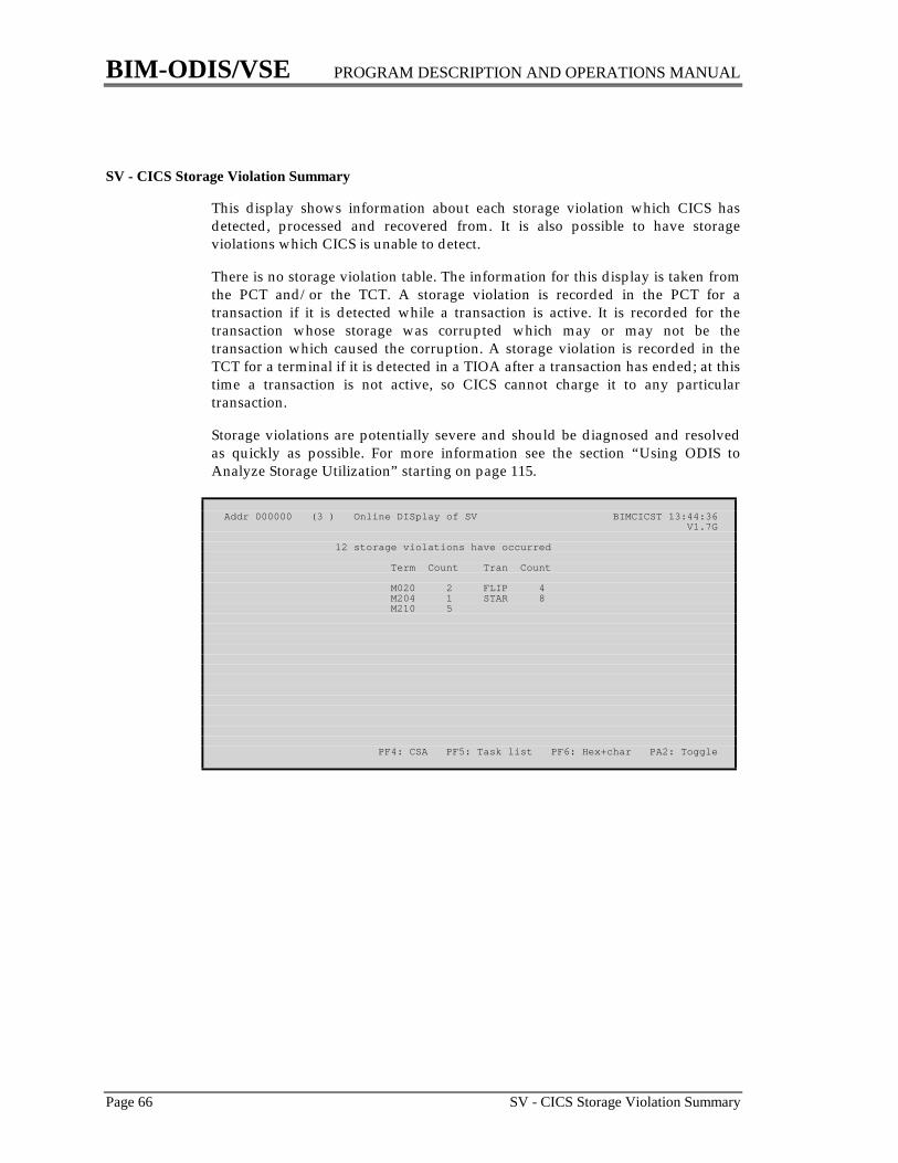
BIM-ODIS/VSE PROGRAM DESCRIPTION AND OPERATIONS MANUAL
Page 66 SV - CICS Storage Violation Summary
SV - CICS Storage Violation Summary
This display shows information about each storage violation which CICS hasdetected, processed and recovered from. It is also possible to have storageviolations which CICS is unable to detect.
There is no storage violation table. The information for this display is taken fromthe PCT and/or the TCT. A storage violation is recorded in the PCT for atransaction if it is detected while a transaction is active. It is recorded for thetransaction whose storage was corrupted which may or may not be thetransaction which caused the corruption. A storage violation is recorded in theTCT for a terminal if it is detected in a TIOA after a transaction has ended; at thistime a transaction is not active, so CICS cannot charge it to any particulartransaction.
Storage violations are potentially severe and should be diagnosed and resolvedas quickly as possible. For more information see the section “Using ODIS toAnalyze Storage Utilization” starting on page 115.
Addr 000000 (3 ) Online DISplay of SV BIMCICST 13:44:36 V1.7G
12 storage violations have occurred
Term Count Tran Count
M020 2 FLIP 4 M204 1 STAR 8 M210 5
PF4: CSA PF5: Task list PF6: Hex+char PA2: Toggle

BIM-ODIS/VSE PROGRAM DESCRIPTION AND OPERATIONS MANUAL
SVA - VSE Shared Virtual Area Page 67
SVA - VSE Shared Virtual Area
The Shared Virtual Area is used to hold programs and other storage which isavailable to all partitions. It is composed of three areas:
1. The System Directory List (SDL), which contains directory entries forfrequently used phases.
2. The Shared Virtual Area (SVA), which contains common programs whichcan be used simultaneously by all partitions.
3. The GETVIS area, which contains storage which may be dynamicallyacquired and used by any partition or by the VSE Supervisor.
The size of the SVA is established during IPL; it is loaded during or after IPL. Itcontains all storage necessary for IBM software plus any other products requiredby the installation. This display may be used to insure that the allocations of theSVA statement during IPL to not waste virtual storage. Since the contents of theSVA are somewhat dynamic, particularly the GETVIS area, each of the threeareas should contain some unused space; as a guideline 10% may be left unused.
Addr 0B7000 (3 ) Online DISplay of SVA BIMCICST 13:48:15 V1.7G--------- SDL -------- --- SVA-24 Programs -- ---- GETVIS-24 ----08 Start addr 0B7050 0C Start addr 0C3000 Start Addr 37900018 Next avail 0BE9D4 10 Next avail 2082B8 End Addr 514FFF End addr 0C2FFF 20 Prog End 363A9F Length 1648K Length 49,072 14 End addr 378FFF In use 836K Unused entries 249 Length 2776K Max used 956K1C Used entries 432 Unused space 1390K Free space 812K Total entries 681 VPOOL size 256K Max ctg free 800K
--- SVA-31 Programs -- ---- GETVIS-31 ---- 24 Start addr 01A00000 Start Addr 01CD0000 28 Next avail 01BCD66B End Addr 01EFFFFF 2C Prog End 01C5C117 Length 2240K 30 End Addr 01CCFFFF In use 1968K Length 2416K Max used 2124K Unused space 571K Free space 1920K Max ctg free 1088K
InUse(above) 1132KThe SVA was last updated 06/09/95 10:30:51 Free(above) 1108K
PF3: SYSCOM PF4: CSA PF5: Task list PF6: Hex+char PA2: Toggle
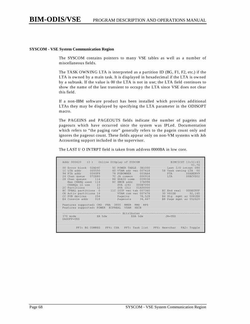
BIM-ODIS/VSE PROGRAM DESCRIPTION AND OPERATIONS MANUAL
Page 68 SYSCOM - VSE System Communication Region
SYSCOM - VSE System Communication Region
The SYSCOM contains pointers to many VSE tables as well as a number ofmiscellaneous fields.
The TASK OWNING LTA is interpreted as a partition ID (BG, F1, F2, etc.) if theLTA is owned by a main task. It is displayed in hexadecimal if the LTA is ownedby a subtask. If the value is 00 the LTA is not in use; the LTA field continues toshow the name of the last transient to occupy the LTA since VSE does not clearthis field.
If a non-IBM software product has been installed which provides additionalLTAs they may be displayed by specifying the LTA parameter in the ODISOPTmacro.
The PAGEINS and PAGEOUTS fields indicate the number of pageins andpageouts which have occurred since the system was IPLed. Documentationwhich refers to “the paging rate” generally refers to the pagein count only andignores the pageout count. These fields appear only on non-VM systems with JobAccounting support included in the supervisor.
The LAST I/O INTRPT field is taken from address 0000BA in low core.
Addr 000420 (3 ) Online DISplay of SYSCOM BIMCICST 13:51:43 V1.7G00 Error block 02AD4C 5C POWER TABLE 3B1000 Last I/O intrpt 0861C LTA addr 005550 60 VTAM adr vec 007418 58 Task owning LTA 0094 PTA addr 0060F8 78 PUBOWNER 003AA4 PTA $$ABERV924 Chan queue 072E80 7C JA common 000918 LTA $$BCVS0228 Chan queues 114 88 SDAID comm 009038 Max CHANQ used 114 DC SMCB addr 37A998 CHANQs in use 23 SVA (24) 000B70002C Partitions 12 SVA (31) 01A00000BC TPBAL partitions 0 11C ICCF vec tab 007360 EC End real 00DECFFFCE Activ partitions 14 VTAM com vec 007478 30 VSIZE 92,160CC PUB devices 254 Pageins 78,528 B4 Stg mgmt ar 0082E8E4 Console addr 018 Pageouts 34,467 B8 Page mgmt ar 052620
Features supported: CKD FBA 3800 RMSR RMS RPSFeatures supported: POWER ECPREAL VSAM XECB
---------------------------------- Attributes ----------------------------------370 mode XA hdw ESA hdw JA=YESDASDFP=YES
PF3: BG COMREG PF4: CSA PF5: Task list PF6: Hex+char PA2: Toggle

BIM-ODIS/VSE PROGRAM DESCRIPTION AND OPERATIONS MANUAL
SYSTEM - Local and Remote Systems Page 69
SYSTEM - Local and Remote Systems
This display shows the status of the local CICS system and any remote (ISE andMRO) CICS systems which are connected to it.
Addr B0E0A4 (3 ) Online DISplay of SYSTEM BIMCICST 13:54:59 V1.7G Sys Term Sessions ---Links-- TCTSE idnt Netname Type I/Os Rec Send Recv Send Connected
00B0E0A4 BATC WBYBTCH1 LUC 0 00B0E534 BIMX BIMAPPL LUC 0 00B0F004 FTRC TR20A LUC 0 00B0DFE4 LI2C LI2C LUC 0 00B063E4 PIRC PIRC MRO 0 3 3 TR1 TS1 No 00B065B4 PISC BIMCICSP LU6 0 00B06664 PROD BIMCICSP LUC 0 00B0F0C4 RXCH BIMRCXHB LUC 0 00B064A4 SUNG WBYCICS LUC 0 00AD3DF4 TEST BIMCICST Loc 0 00B0F184 TR30 TR30A LUC 0 00B0F244 TR40 TR40A LUC 0 00B0F304 TR50 TR50D LUC 0 00B09004 VSHR WBYCICST LUC 0
PF4: CSA PF5: Task list PF6: Hex+char PA2: Toggle
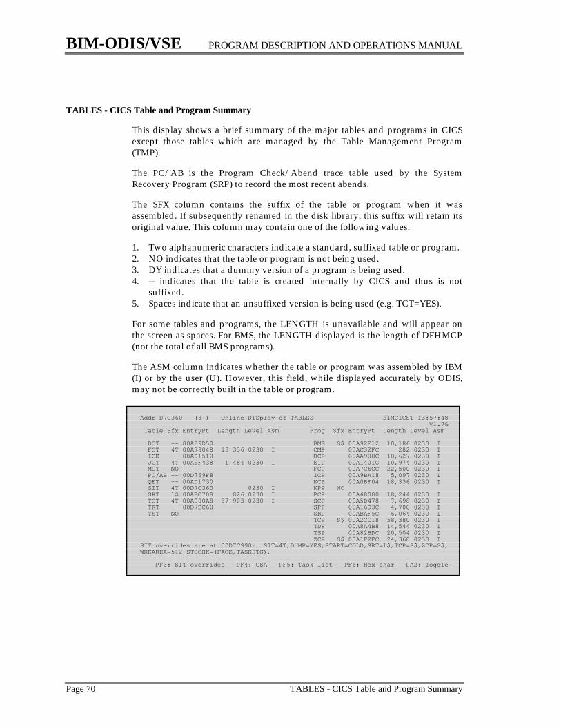
BIM-ODIS/VSE PROGRAM DESCRIPTION AND OPERATIONS MANUAL
Page 70 TABLES - CICS Table and Program Summary
TABLES - CICS Table and Program Summary
This display shows a brief summary of the major tables and programs in CICSexcept those tables which are managed by the Table Management Program(TMP).
The PC/AB is the Program Check/Abend trace table used by the SystemRecovery Program (SRP) to record the most recent abends.
The SFX column contains the suffix of the table or program when it wasassembled. If subsequently renamed in the disk library, this suffix will retain itsoriginal value. This column may contain one of the following values:
1. Two alphanumeric characters indicate a standard, suffixed table or program.2. NO indicates that the table or program is not being used.3. DY indicates that a dummy version of a program is being used.4. -- indicates that the table is created internally by CICS and thus is not
suffixed.5. Spaces indicate that an unsuffixed version is being used (e.g. TCT=YES).
For some tables and programs, the LENGTH is unavailable and will appear onthe screen as spaces. For BMS, the LENGTH displayed is the length of DFHMCP(not the total of all BMS programs).
The ASM column indicates whether the table or program was assembled by IBM(I) or by the user (U). However, this field, while displayed accurately by ODIS,may not be correctly built in the table or program.
Addr D7C360 (3 ) Online DISplay of TABLES BIMCICST 13:57:48 V1.7G Table Sfx EntryPt Length Level Asm Prog Sfx EntryPt Length Level Asm
DCT -- 00A89D50 BMS S$ 00A92E12 10,186 0230 I FCT 4T 00A78048 13,336 0230 I CMP 00AC32FC 282 0230 I ICE -- 00AD1510 DCP 00AA908C 10,627 0230 I JCT 4T 00A9F438 1,484 0230 I EIP 00A1401C 10,974 0230 I MCT NO FCP 00A7C6CC 22,500 0230 I PC/AB -- 00D769F8 ICP 00A9BA18 5,097 0230 I QET -- 00AD1730 KCP 00A0BF04 18,336 0230 I SIT 4T 00D7C360 0230 I KPP NO SRT 1$ 00ABC708 826 0230 I PCP 00A68000 18,244 0230 I TCT 4T 00A000A8 37,903 0230 I SCP 00A5D478 7,698 0230 I TRT -- 00D7BC60 SPP 00A16D3C 4,700 0230 I TST NO SRP 00ABAF5C 6,064 0230 I TCP S$ 00A2CC18 58,380 0230 I TDP 00A8A4B8 14,544 0230 I TSP 00A82BDC 20,504 0230 I ZCP S$ 00A1F2FC 24,368 0230 ISIT overrides are at 00D7C990: SIT=4T,DUMP=YES,START=COLD,SRT=1$,TCP=S$,ZCP=S$,WRKAREA=512,STGCHK=(FAQE,TASKSTG),
PF3: SIT overrides PF4: CSA PF5: Task list PF6: Hex+char PA2: Toggle

BIM-ODIS/VSE PROGRAM DESCRIPTION AND OPERATIONS MANUAL
TASK - CICS Active and Suspended Tasks Page 71
TASK - CICS Active and Suspended Tasks
This display shows the tasks on the active and suspended DCA (DispatchControl Area) chains. An active task is one which is running, ready to run orwaiting for an event which should be completed in a short period of time, such asa file I/O. A suspended task is one which is waiting for an event which may becompleted in a longer period of time, such as a read from a terminal.
The active tasks will be displayed in priority sequence. The suspended tasks willbe displayed in LIFO sequence.
The TERM column will contain “----” if the task is not running at a terminal.
The MOD column indicates which service module of CICS is active on behalf ofthe task, for example TCP for Terminal Control Program. If this column contains“---” no CICS module is currently serving this task. In some cases, two CICSservice modules will be active simultaneously. These are shown as follows:
B+T BMS and TCPF+K FCP and KCPI+K ICP and KCPT+K TSP and KCP
The LAST REQ column indicates the last CICS request made to Task ControlProgram by the task. This may have been done by either the user's program itselfor by a CICS service module on behalf of the user's program. If this columncontains “--NONE--” the task has not issued a CICS service request which hasbeen recorded in its TCA.
The DISPATCH CNTL column indicates the task's current dispatching status.When a new task is placed on the active DCA chain, CICS sets its dispatchingstatus to either “waiting for AMAX task limit” or “waiting for CMAX task limit”.This is done for internal purposes and does not necessarily indicate that theselimits have been exceeded.
The RESOURCE column indicates, if possible, which resource the task is waitingfor. It may be one of the following:
1. For file I/O or access to a file, this shows the file name.2. For a single ECB this shows the address of the ECB.3. For a list of ECBs this shows the address of the list.4. For an ENQ this shows the name of the resource.5. For a VSAM file waiting for a shared string this shows “SR STRING”.
A plus sign (+) between the TRAN and TERM columns indicates that there aremore active or suspended tasks to be displayed but there is no more room on thescreen to display them. If this happens, three methods may be used to display theadditional tasks:
1. A numeric entry name may be specified to indicate the number oftransactions to be skipped before the display begins.
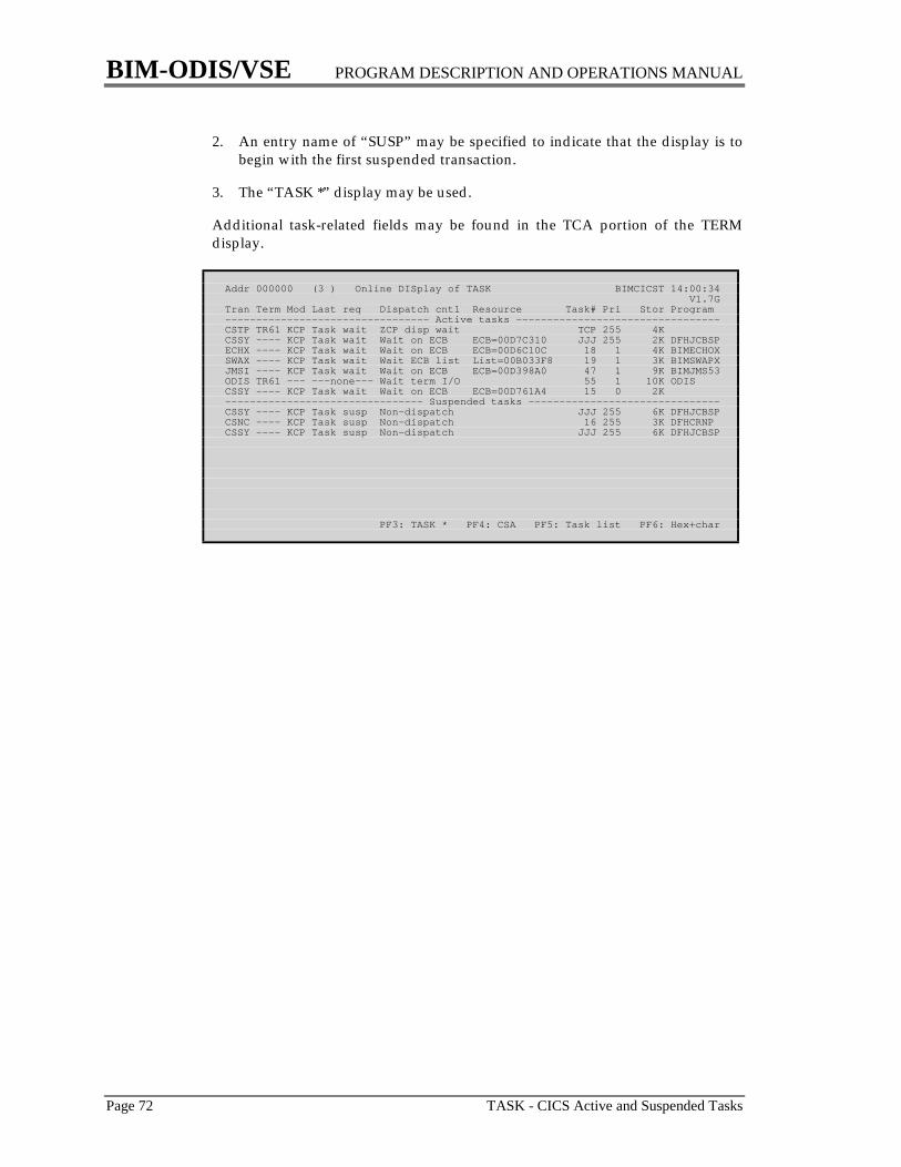
BIM-ODIS/VSE PROGRAM DESCRIPTION AND OPERATIONS MANUAL
Page 72 TASK - CICS Active and Suspended Tasks
2. An entry name of “SUSP” may be specified to indicate that the display is tobegin with the first suspended transaction.
3. The “TASK *” display may be used.
Additional task-related fields may be found in the TCA portion of the TERMdisplay.
Addr 000000 (3 ) Online DISplay of TASK BIMCICST 14:00:34 V1.7GTran Term Mod Last req Dispatch cntl Resource Task# Pri Stor Program--------------------------------- Active tasks ---------------------------------CSTP TR61 KCP Task wait ZCP disp wait TCP 255 4KCSSY ---- KCP Task wait Wait on ECB ECB=00D7C310 JJJ 255 2K DFHJCBSPECHX ---- KCP Task wait Wait on ECB ECB=00D6C10C 18 1 4K BIMECHOXSWAX ---- KCP Task wait Wait ECB list List=00B033F8 19 1 3K BIMSWAPXJMSI ---- KCP Task wait Wait on ECB ECB=00D398A0 47 1 9K BIMJMS53ODIS TR61 --- ---none--- Wait term I/O 55 1 10K ODISCSSY ---- KCP Task wait Wait on ECB ECB=00D761A4 15 0 2K-------------------------------- Suspended tasks -------------------------------CSSY ---- KCP Task susp Non-dispatch JJJ 255 6K DFHJCBSPCSNC ---- KCP Task susp Non-dispatch 16 255 3K DFHCRNPCSSY ---- KCP Task susp Non-dispatch JJJ 255 6K DFHJCBSP
PF3: TASK * PF4: CSA PF5: Task list PF6: Hex+char
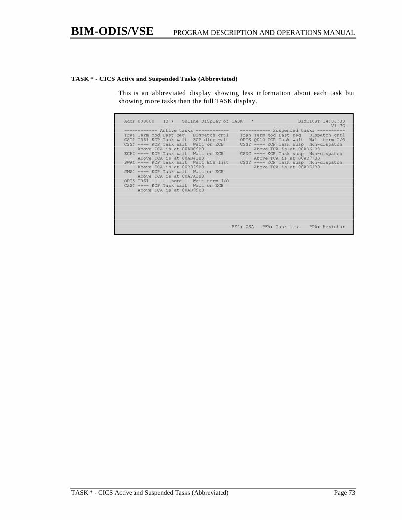
BIM-ODIS/VSE PROGRAM DESCRIPTION AND OPERATIONS MANUAL
TASK * - CICS Active and Suspended Tasks (Abbreviated) Page 73
TASK * - CICS Active and Suspended Tasks (Abbreviated)
This is an abbreviated display showing less information about each task butshowing more tasks than the full TASK display.
Addr 000000 (3 ) Online DISplay of TASK * BIMCICST 14:03:30 V1.7G------------ Active tasks ------------ ----------- Suspended tasks ----------Tran Term Mod Last req Dispatch cntl Tran Term Mod Last req Dispatch cntlCSTP TR61 KCP Task wait ZCP disp wait ODIS Q010 TCP Task wait Wait term I/OCSSY ---- KCP Task wait Wait on ECB CSSY ---- KCP Task susp Non-dispatch Above TCA is at 00ADC9B0 Above TCA is at 00AD61B0ECHX ---- KCP Task wait Wait on ECB CSNC ---- KCP Task susp Non-dispatch Above TCA is at 00AD41B0 Above TCA is at 00AD79B0SWAX ---- KCP Task wait Wait ECB list CSSY ---- KCP Task susp Non-dispatch Above TCA is at 00B029B0 Above TCA is at 00ADE9B0JMSI ---- KCP Task wait Wait on ECB Above TCA is at 00AFA1B0ODIS TR61 --- ---none--- Wait term I/OCSSY ---- KCP Task wait Wait on ECB Above TCA is at 00AD99B0
PF4: CSA PF5: Task list PF6: Hex+char
BIM-ODIS/VSE PROGRAM DESCRIPTION AND OPERATIONS MANUAL
Page 74 TERM - CICS Terminal Control Table
TERM - CICS Terminal Control Table
The TCT contains one entry for each terminal that is defined to CICS. If a task isrunning at the terminal this display will also show information from the task'sTCA (Transaction Control Area).
The “USER AREA” field shows the length and beginning address of the TerminalUser Area (TUA) for the terminal.
The “SK” field shows the operator's security keys. This is a combination of twodifferent fields in the TCTTE, TCTTESK (keys 1-24) and TCTESKE (keys 25-64).The leftmost bit represents key 64, and the rightmost bit represents key 1.
The TRANSACTIONS field indicates the number of transactions run since thelast terminal operator signed off; if only one (or no) terminal operator has signedon, this will also be the number of transactions run since CICS was started. Forsome terminal types CICS does not record transaction statistics.
For some terminal types CICS does not record message statistics.
The lower portion of the center column is displayed only for 3270 displayterminals and 328x printers. In addition, a few fields apply to only VTAM orBTAM terminals.
The DSA ADDR is the address of a block of storage which is unique to thetransaction running at the terminal. (This is not related to the DSA which ismanaged by the PAM). Its use is dependent upon the programming language asfollows:
1. For Macro Level COBOL programs it is a copy of the TGT (an area definedby the COBOL compiler, not by CICS).
2. For Command Level COBOL programs it is a copy of WORKING-STORAGEplus the TGT.
3. For Command Level assembler programs it is the DFHEISTG area.
4. For PL/I programs it is the chain of PL/I DSAs.
5. For RPG programs it is the entire program.
The EIS ADDR is the address of the EXEC (Command Level) Interface Structure,which contains the EIB (Exec Interface Block).
The LOCK ECB ADR is taken from TCALCKAD. The WAIT ECB ADR is takenfrom TCATCEA. These fields will be useful when the task is waiting for an ENQor ECB.
For a description of the DC, LAST REQ and SERVICE MODULE fields see theTASK display on page 71.
BIM-ODIS/VSE PROGRAM DESCRIPTION AND OPERATIONS MANUAL
TERM - CICS Terminal Control Table Page 75
The REG 14 field is taken from the save area at TCACCRS+0 and often containsthe address in the program where the last CICS macro level instruction wasissued.
USER STORAGE shows the total amount of storage chained off the TCA,rounded to the nearest 1K bytes. This includes the TCA itself, TWA, user storage,file I/O areas, temporary storage I/O areas, etc. For transactions defined withCLASS=SHORT, it includes only storage which has been GETMAINed. Sincestorage for CLASS=LONG transactions is allocated by full pages, there may beadditional storage in one or more pages which has been reserved for thetransaction but which has not yet been GETMAINed.
TIOA STORAGE shows the total amount of TIOA storage chained off the TCTTE,rounded to the nearest 1K bytes.
Special Entry Names
After a display for a terminal has been displayed it is possible to symbolicallyaddress many of its related storage areas and display them in hexadecimal andcharacter (“core dump” format). To do this enter one of the following specialnames in the entry field on the top of the screen (overstriking the terminal ID):
DCA Dispatch Control AreaDSA Dynamic Storage AreaEIB Exec Interface BlockEIS Exec Interface StructureHLL High Level Language save areaLECB Lock ECBNIB Node Initialization Block (VTAM only)RPL Request Parameter List (VTAM only)R14 Contents of register 14 from the save areaPST DL/I Partition Specification TableSTCA System area of TCATCA User area of TCATCTLE TCT line entry for this terminalTCTSE TCT system entry for this terminalTCTX TCTTE extensionTIOA Current Terminal I/O AreaTWA Transaction Work AreaUTCA User area of TCAWECB Wait ECBWS COBOL WORKING-STORAGE
Note that the WS special entry name is valid only for Command Level COBOLprograms. The LECB and WECB special entry names may be used to determinethe resource that the task is waiting for. It may be necessary to examine thestorage immediately preceding these addresses to find further information. Forexample, when a task is waiting for VSAM strings for a file the ECB address willpoint X'1A' bytes into the file's FCT entry. The file name may thus be found atX'1A' bytes before the ECB.

BIM-ODIS/VSE PROGRAM DESCRIPTION AND OPERATIONS MANUAL
Page 76 TERM - CICS Terminal Control Table
MRO Considerations
In a Multi-Region Operation (MRO) environment, CICS builds a number ofdifferent types of TCTTEs. ODIS processes them as follows:
1. Relay TCTTEs are used for the transmission of data between CICS partitions.They can be viewed on all of the TERM displays.
2. Surrogate TCTTEs are built dynamically by CICS when a cross systemtransaction is started and removed when the transaction ends. They can beviewed on the TERM display while they exist. (But since they are not in thestandard TCTTE chain, they cannot be viewed on the TERM * and TERM **displays, nor can they be viewed sequentially using the PF1 key.)
3. Skeleton TCTTEs are used to identify the remote terminals which may beconnected to a CICS system. They are very short and are not in the standardTCTTE format. They may be viewed by explicitly specifying TERM XXXX,but they cannot be viewed on the TERM * and TERM ** displays.
Addr B01154 (3 ) Online DISplay of TERM TR61 BIMCICST 14:11:27 V1.7G04 Terminal type R3277 B1 Input msgs 70 ----- System TCA -----05 Terminal model 2 B5 Outpt msgs 79 11 Task number 5508 First TIOA 00AD2580 B9 Transmit errs 0 14 Trans ID ODIS0C Activ TIOA 00000000 BB Transactions 3 34 Program ODIS18 User 0/00000000 C5 Access method VTAM 40 DSA addr 00B12800 User ID Storage violatns 0 7C EIS addr 00AF9B4025 Operator ID SK 0000000000000001 -------- 3270 -------- ------ User TCA ------ Oper RSL key 000000 30 Cursor addr 48 Address 00AF91B02B Oper priority 0 32 Attention ID Enter 04 Lock ECB 00000000AF Term priority 0 34 BMS map 14 Wait ECB 00B0115470 RPL addr 00AF7CF4 48 Default buffer 1920 1A Priority 17C Next trans ID 4A Default size 24x 80 18 DC Wait term I/O 4C Altern buffer 0 19 Last req ---none--- LU name TR61 4E Altern size 0x 0 1D Service module ---6C NIB addr 00B01314 A0 Reg 14 00A1574A07 Status: In service Transceive User storage 10KC6 Last op: TIOA storage 0K33 3270 features: ALARM UCTRAN EXTDS COLOR Strings in use 0Other attributes: Shippable Transient term Connected to VTAM
PF1: Next term PF2: First term PF3: Term summary PF4: CSA PF5: Task list
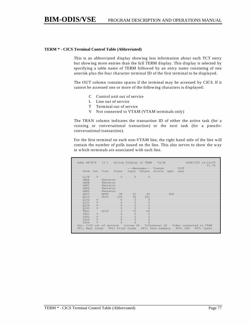
BIM-ODIS/VSE PROGRAM DESCRIPTION AND OPERATIONS MANUAL
TERM * - CICS Terminal Control Table (Abbreviated) Page 77
TERM * - CICS Terminal Control Table (Abbreviated)
This is an abbreviated display showing less information about each TCT entrybut showing more entries than the full TERM display. This display is selected byspecifying a table name of TERM followed by an entry name consisting of oneasterisk plus the four character terminal ID of the first terminal to be displayed.
The OUT column contains spaces if the terminal may be accessed by CICS. If itcannot be accessed one or more of the following characters is displayed:
C Control unit out of serviceL Line out of serviceT Terminal out of serviceV Not connected to VTAM (VTAM terminals only)
The TRAN column indicates the transaction ID of either the active task (for arunning or conversational transaction) or the next task (for a pseudo-conversational transaction).
For the first terminal on each non-VTAM line, the right hand side of the line willcontain the number of polls issued on the line. This also serves to show the wayin which terminals are associated with each line.
Addr AE7A74 (3 ) Online DISplay of TERM *LL7B BIMCICST 14:14:09 V1.7G ---Messages-- Transm ICCF Term Out Tran Trans Input Output errors Oper user
LL7B V 0 0 0 LM0A Skeleton LM0B Skeleton LM0C Skeleton LM0X Skeleton LM00 Skeleton Q003 AFAX 38 41 44 SYA Q010 ODIS 104 92 291 Q152 V 0 0 0 Q153 V 0 0 0 Q254 V 0 0 0 Q255 V 0 0 0 TR61 ODIS 3 75 84 TS01 V 0 0 0 TS02 V 0 0 0 TS03 V 0 0 0 TS04 V 0 0 0Out: C=CU out of service L=Line OS T=Terminal OS V=Not connected to VTAMPF1: Next terms PF2: First terms PF3: Term summary PF4: CSA PF5: Tasks
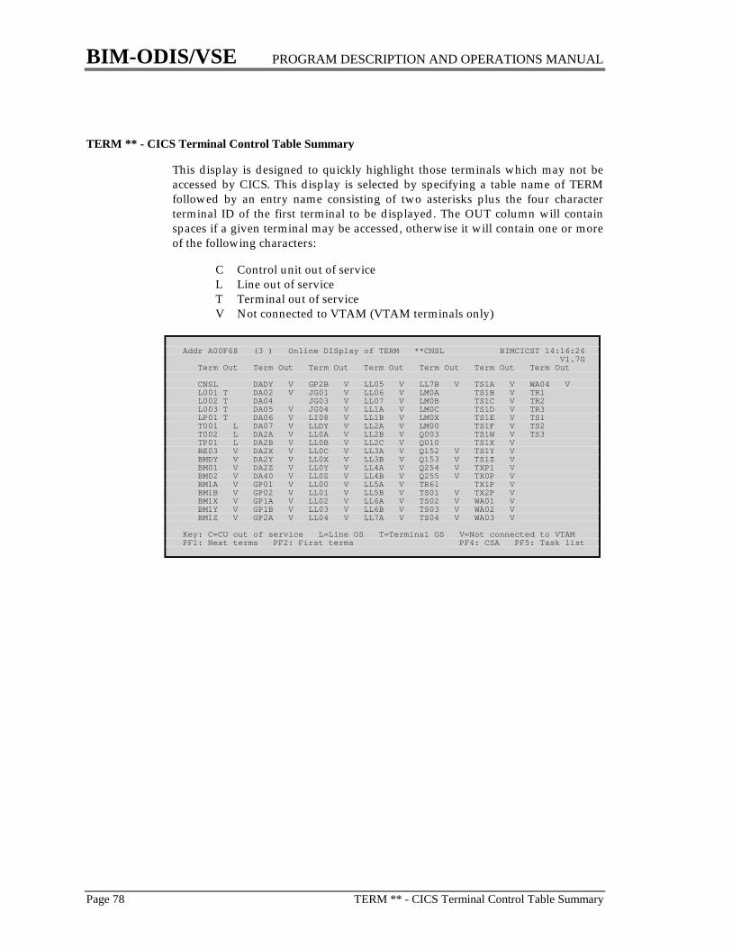
BIM-ODIS/VSE PROGRAM DESCRIPTION AND OPERATIONS MANUAL
Page 78 TERM ** - CICS Terminal Control Table Summary
TERM ** - CICS Terminal Control Table Summary
This display is designed to quickly highlight those terminals which may not beaccessed by CICS. This display is selected by specifying a table name of TERMfollowed by an entry name consisting of two asterisks plus the four characterterminal ID of the first terminal to be displayed. The OUT column will containspaces if a given terminal may be accessed, otherwise it will contain one or moreof the following characters:
C Control unit out of serviceL Line out of serviceT Terminal out of serviceV Not connected to VTAM (VTAM terminals only)
Addr A00F68 (3 ) Online DISplay of TERM **CNSL BIMCICST 14:16:26 V1.7G Term Out Term Out Term Out Term Out Term Out Term Out Term Out
CNSL DADY V GP2B V LL05 V LL7B V TS1A V WA04 V L001 T DA02 V JG01 V LL06 V LM0A TS1B V TR1 L002 T DA04 JG03 V LL07 V LM0B TS1C V TR2 L003 T DA05 V JG04 V LL1A V LM0C TS1D V TR3 LP01 T DA06 V LI08 V LL1B V LM0X TS1E V TS1 T001 L DA07 V LLDY V LL2A V LM00 TS1F V TS2 T002 L DA2A V LL0A V LL2B V Q003 TS1W V TS3 TP01 L DA2B V LL0B V LL2C V Q010 TS1X V BE03 V DA2X V LL0C V LL3A V Q152 V TS1Y V BMDY V DA2Y V LL0X V LL3B V Q153 V TS1Z V BM01 V DA2Z V LL0Y V LL4A V Q254 V TXP1 V BM02 V DA40 V LL0Z V LL4B V Q255 V TX0P V BM1A V GP01 V LL00 V LL5A V TR61 TX1P V BM1B V GP02 V LL01 V LL5B V TS01 V TX2P V BM1X V GP1A V LL02 V LL6A V TS02 V WA01 V BM1Y V GP1B V LL03 V LL6B V TS03 V WA02 V BM1Z V GP2A V LL04 V LL7A V TS04 V WA03 V
Key: C=CU out of service L=Line OS T=Terminal OS V=Not connected to VTAMPF1: Next terms PF2: First terms PF4: CSA PF5: Task list
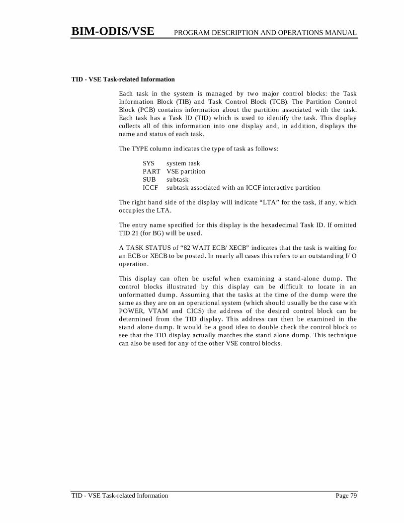
BIM-ODIS/VSE PROGRAM DESCRIPTION AND OPERATIONS MANUAL
TID - VSE Task-related Information Page 79
TID - VSE Task-related Information
Each task in the system is managed by two major control blocks: the TaskInformation Block (TIB) and Task Control Block (TCB). The Partition ControlBlock (PCB) contains information about the partition associated with the task.Each task has a Task ID (TID) which is used to identify the task. This displaycollects all of this information into one display and, in addition, displays thename and status of each task.
The TYPE column indicates the type of task as follows:
SYS system taskPART VSE partitionSUB subtaskICCF subtask associated with an ICCF interactive partition
The right hand side of the display will indicate “LTA” for the task, if any, whichoccupies the LTA.
The entry name specified for this display is the hexadecimal Task ID. If omittedTID 21 (for BG) will be used.
A TASK STATUS of “82 WAIT ECB/XECB” indicates that the task is waiting foran ECB or XECB to be posted. In nearly all cases this refers to an outstanding I/Ooperation.
This display can often be useful when examining a stand-alone dump. Thecontrol blocks illustrated by this display can be difficult to locate in anunformatted dump. Assuming that the tasks at the time of the dump were thesame as they are on an operational system (which should usually be the case withPOWER, VTAM and CICS) the address of the desired control block can bedetermined from the TID display. This address can then be examined in thestand alone dump. It would be a good idea to double check the control block tosee that the TID display actually matches the stand alone dump. This techniquecan also be used for any of the other VSE control blocks.
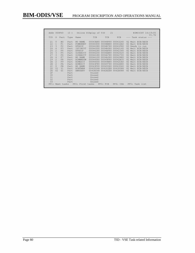
BIM-ODIS/VSE PROGRAM DESCRIPTION AND OPERATIONS MANUAL
Page 80 TID - VSE Task-related Information
Addr 000FD0 (3 ) Online DISplay of TID 21 BIMCICST 14:19:05 V1.7GTID S Part Type Name TIB TCB PCB --- Task status ---
21 0 BG Part NO NAME 00043E80 00048F80 00043240 82 Wait ECB/XECB 22 1 F1 Part POWERNET 00044400 0004BB80 00041DA0 82 Wait ECB/XECB 23 3 F2 Part DFHSIP 00044380 0004B780 00041F80 83 Ready to run 24 4 F3 Part ISTINCVT 00044300 0004B380 00042160 82 Wait ECB/XECB 25 2 F4 Part DFHSIP 00044280 0004AF80 00042340 82 Wait ECB/XECB 26 3 F5 Part $JOBACCT 00044200 0004AB80 00042520 82 Wait ECB/XECB 27 3 F6 Part $JOBACCT 00044180 0004A780 00042700 82 Wait ECB/XECB 28 4 F7 Part NO NAME 00044100 0004A380 000428E0 82 Wait ECB/XECB 29 2 F8 Part BIMWNDOW 00044080 00049F80 00042AC0 82 Wait ECB/XECB 2A 2 F9 Part BIMEDIT 00044000 00049B80 00042CA0 82 Wait ECB/XECB 2B 2 FA Part BIMEDIT 00043F80 00049780 00042E80 82 Wait ECB/XECB 2C 0 FB Part NO NAME 00043F00 00049380 00043060 82 Wait ECB/XECB 2D Y1 Y1 Part BIMTMAN 00430268 004302E8 00430088 82 Wait ECB/XECB 2E G1 G1 Part AW8SERV 0042B268 0042B2E8 0042B088 82 Wait ECB/XECB 2F Part Unused 30 Part Unused 31 Part Unused 32 Part Unused 33 Part UnusedPF1: Next tasks PF2: First tasks PF3: PIB PF4: CSA PF5: Task list
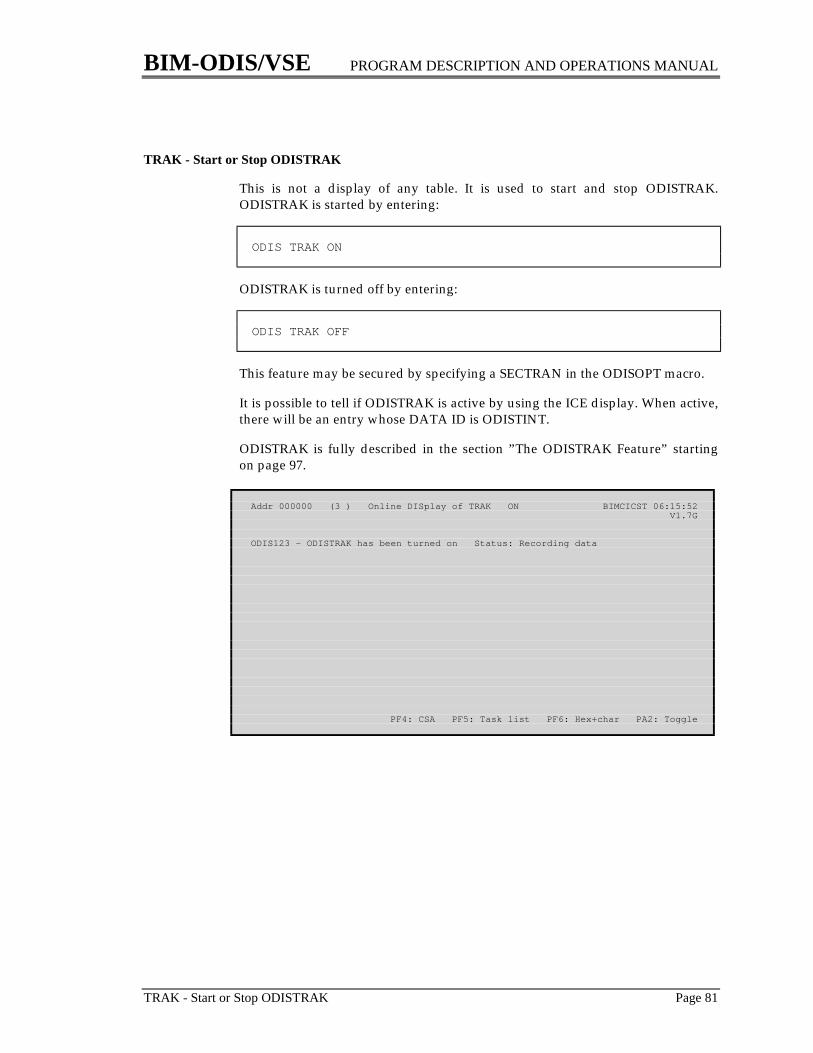
BIM-ODIS/VSE PROGRAM DESCRIPTION AND OPERATIONS MANUAL
TRAK - Start or Stop ODISTRAK Page 81
TRAK - Start or Stop ODISTRAK
This is not a display of any table. It is used to start and stop ODISTRAK.ODISTRAK is started by entering:
ODIS TRAK ON
ODISTRAK is turned off by entering:
ODIS TRAK OFF
This feature may be secured by specifying a SECTRAN in the ODISOPT macro.
It is possible to tell if ODISTRAK is active by using the ICE display. When active,there will be an entry whose DATA ID is ODISTINT.
ODISTRAK is fully described in the section ”The ODISTRAK Feature” startingon page 97.
Addr 000000 (3 ) Online DISplay of TRAK ON BIMCICST 06:15:52 V1.7G
ODIS123 - ODISTRAK has been turned on Status: Recording data
PF4: CSA PF5: Task list PF6: Hex+char PA2: Toggle
BIM-ODIS/VSE PROGRAM DESCRIPTION AND OPERATIONS MANUAL
Page 82 TRAN - CICS Program Control Table
TRAN - CICS Program Control Table
The PCT contains one entry for each transaction (not program) defined to CICS.
The STORAGE VIOLATNS field indicates how many times CICS determinedthat a storage violation has occurred for this transaction. The storage violationmay or may not have been caused by this transaction. Similarly, it is possible forthis transaction to cause a storage violation for another transaction; this eventwould not be recorded for this transaction.
The STORAGE FREEZE field is not defined by the systems programmer in theDFHPCT TYPE=ENTRY macro. It is set during execution by the CSFE transactionwhich is documented in the CICS Operator's Guide.
If a PCT has been assembled with a TWA SIZE that is too small it is a simple (andrelatively safe) matter to correct by using the storage alteration facilities of ODIS.Most other parameters can also be changed in this way, thus making itunnecessary to take CICS down and up again just to make a simple table change.
Addr A64970 (3 ) Online DISplay of TRAN SPOL BIMCICST 06:18:38 V1.7G08 Times used 0 14 Init prog BIMSPPRT 0D Command level No0C Class 0 0D Storage freeze No0E Tran priority 1 28 Msg journal ID 0 0D Trans dump Yes0F Security key 1 29 NEP class 0 3F ASRA dump No10 Resourc sec lvl 0 2E Anticip pages 0 3F ASRB dump No12 TWA size 0 34 Extra stg req 0 11 External sec No1D Times restarted 0 40 Deadlock TO 0 11 RSL check No1E Stall purged 0 07 Read timeout 0 1C Term err purge No20 Storage violatns 0 1C Stall purge No50 Partn set (none)58 Profile ID 3E DTB No 1C Status Enabled 3E Restart No 3E Alt screen size No 24 Devices All 0D Trace Yes 27 Read ahead Q No
PF1: Next tran PF2: First tran PF3: First prog PF4: CSA PF5: Task list

BIM-ODIS/VSE PROGRAM DESCRIPTION AND OPERATIONS MANUAL
TRAN * - CICS Program Control Table (Abbreviated) Page 83
TRAN * - CICS Program Control Table (Abbreviated)
This is an abbreviated display showing less information about each PCT entrybut showing more entries than the full TRAN display. This display is selected byspecifying a table name of TRAN followed by an asterisk plus the four charactertransaction ID of the first transaction to be displayed.
Addr AFF574 (3 ) Online DISplay of TRAN *CNSL BIMCICST 06:22:09 V1.7G Stall Stg Tran Program Used Cl Pri Sec RSL purged vio Profile
CNSL BIMCNSOL 42 0 1 1 0 0 0 ALT CNST SJACNSOL 0 0 1 1 0 0 0 DFHCICST CORE DFHBUG 0 0 1 1 0 0 0 CPMI DFHMIRS 0 0 1 1 0 0 0 DFHCICSA CQRY DFHQRY 2 0 255 1 0 0 0 DFHCICST CRSQ DFHCRQ 9 0 1 1 0 0 0 DFHCICSA CRSR DFHCRS 0 0 1 1 0 0 0 DFHCICSA CRSY DFHRMSY 0 0 1 1 0 0 0 DFHCICST CRTE DFHRTE 0 0 1 1 0 0 0 DFHCICST CSAC DFHACP 1 0 255 1 0 0 0 DFHCICST CSCY DFHCPY 0 0 1 1 0 0 0 DFHCICST CSFE DFHFEP 0 0 255 1 0 0 0 DFHCICST CSFR DFHFED1 0 0 255 1 0 0 0 DFHCICST CSFU DFHFCU 1 0 1 1 0 0 0 DFHCICST CSGM DFHGMM 0 0 1 1 0 0 0 DFHCICST CSIR DFHCRR 0 0 1 1 0 0 0 DFHCICSA CSJC DFHJCBSP 0 0 255 1 0 0 0 DFHCICST CSKP DFHAKP 0 0 1 1 0 0 0 DFHCICSTPF1: Next trans PF2: First trans PF4: CSA PF5: Task list PF6: Hex+char
BIM-ODIS/VSE PROGRAM DESCRIPTION AND OPERATIONS MANUAL
Page 84 TS - CICS Temporary Storage
TS - CICS Temporary Storage
Temporary Storage is a facility used as a “scratch” pad to store data outside of atask; it remains available after the task which created it has terminated. TheTemporary Storage Table (TST) does not control all of temporary storage asmight be suspected; it only defines those elements which are recoverable orremote. ODIS does not examine the TST if one exists.
In order to facilitate displays of Temporary Storage data IDs which containhexadecimal characters, the entry name is assumed to be generic. For example,specifying TS ABC would cause the display to begin with the first data ID havingABC as its first three characters; the last five characters of the data ID would beignored.
The RECORDS WRITTEN and RECORDS READ fields only apply to temporarystorage queues; they are not applicable to single element entries. The RECORDSWRITTEN field indicates how many records have been written. The RECORDSREAD field indicates the next sequential record to be read.
The LENGTH field is always a multiple of the segment size (see the TSCOMdisplay on page 86) if the data is stored on auxiliary temporary storage.
For data in MAIN temporary storage, the DATA ADDR field points to itslocation in main storage. This address may be used to display the data by usingthe hexadecimal and character display of ODIS.
Some of the entries in Temporary Storage may be written by various CICSmanagement programs. Some of these may be identified by the following DATAIDs:
** Basic Mapping SupportX'FA'+NXQ+ Used for Temporary Storage records larger than CI size
numberX'FE' FERSX'FF'+DTB Dynamic Transaction backout

BIM-ODIS/VSE PROGRAM DESCRIPTION AND OPERATIONS MANUAL
TS - CICS Temporary Storage Page 85
Addr ADF750 (3 ) Online DISplay of TS AXQ003V6 BIMCICST 06:25:44 V1.7G TSUTE ---Records-- Data addr Data ID- -Data ID in hex- Type Written Read Length Fac addr
00ADF750 AXQ003V6 C1E7D8F0F0F3E5F6 Queue 1 2 14 Main 0125280000ADF740 AXQ00340 C1E7D8F0F0F3F4F0 Queue 11 12 143 Main 01252B8000ADF730 IEOPADDQ C9C5D6D7C1C4C4D8 Queue 1 1 20 Main 01252F0000ADF720 ITIDKV89 C9E3C9C4D2E5F8F9 Queue 1 2 1,252 Main 01187B0000ADF710 ODISTRAK D6C4C9E2E3D9C1D2 Queue 1 1 128 Aux 00010002
PF1: Next data ID PF2: First data ID PF3: TSCOM PF4: CSA PF5: Task list
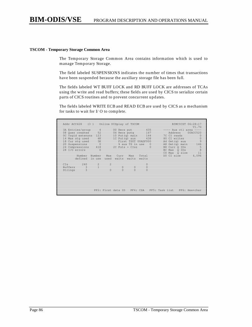
BIM-ODIS/VSE PROGRAM DESCRIPTION AND OPERATIONS MANUAL
Page 86 TSCOM - Temporary Storage Common Area
TSCOM - Temporary Storage Common Area
The Temporary Storage Common Area contains information which is used tomanage Temporary Storage.
The field labeled SUSPENSIONS indicates the number of times that transactionshave been suspended because the auxiliary storage file has been full.
The fields labeled WT BUFF LOCK and RD BUFF LOCK are addresses of TCAsusing the write and read buffers; these fields are used by CICS to serialize certainparts of CICS routines and to prevent concurrent updates.
The fields labeled WRITE ECB and READ ECB are used by CICS as a mechanismfor tasks to wait for I/O to complete.
Addr ACC428 (3 ) Online DISplay of TSCOM BIMCICST 06:28:17 V1.7G3A Entries/group 4 00 Recs put 435 ---- Aux ctl area ----08 Ques created 52 04 Recs putq 147 Address 00ACC5200C Tsgid extensns 123 10 Put(q) main 144 7C CI reads 014 Max stg used 4K 1C Put(q) aux 438 80 CI writes 018 Cur stg used 3K First TSUT 00ADF000 A4 Get(q) aux 920 Suspensions 0 % aux TS in use 0 A8 Get(q) main 14624 Compressions 418 2C Puts > CIsz 0 B8 Curr Q IDs 528 I/O errors 0 BC Max Q IDs 8 C0 Max Q size 11 Number Number Max Curr Max Total D0 CI size 4,096 defined in use used waits waits waits
CIs 240 2 2 0Buffers 3 1 0 0 0Strings 3 0 0 0 0
PF2: First data ID PF4: CSA PF5: Task list PF6: Hex+char
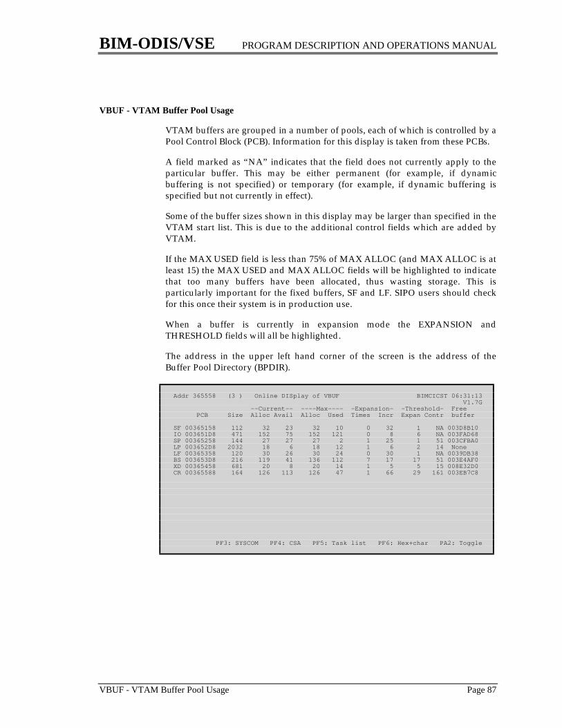
BIM-ODIS/VSE PROGRAM DESCRIPTION AND OPERATIONS MANUAL
VBUF - VTAM Buffer Pool Usage Page 87
VBUF - VTAM Buffer Pool Usage
VTAM buffers are grouped in a number of pools, each of which is controlled by aPool Control Block (PCB). Information for this display is taken from these PCBs.
A field marked as “NA” indicates that the field does not currently apply to theparticular buffer. This may be either permanent (for example, if dynamicbuffering is not specified) or temporary (for example, if dynamic buffering isspecified but not currently in effect).
Some of the buffer sizes shown in this display may be larger than specified in theVTAM start list. This is due to the additional control fields which are added byVTAM.
If the MAX USED field is less than 75% of MAX ALLOC (and MAX ALLOC is atleast 15) the MAX USED and MAX ALLOC fields will be highlighted to indicatethat too many buffers have been allocated, thus wasting storage. This isparticularly important for the fixed buffers, SF and LF. SIPO users should checkfor this once their system is in production use.
When a buffer is currently in expansion mode the EXPANSION andTHRESHOLD fields will all be highlighted.
The address in the upper left hand corner of the screen is the address of theBuffer Pool Directory (BPDIR).
Addr 365558 (3 ) Online DISplay of VBUF BIMCICST 06:31:13 V1.7G --Current-- ----Max---- -Expansion- -Threshold- Free PCB Size Alloc Avail Alloc Used Times Incr Expan Contr buffer
SF 00365158 112 32 23 32 10 0 32 1 NA 003D8B10IO 003651D8 471 152 75 152 121 0 8 6 NA 003FAD68SP 00365258 144 27 27 27 2 1 25 1 51 003CFBA0LP 003652D8 2032 18 6 18 12 1 6 2 14 NoneLF 00365358 120 30 26 30 24 0 30 1 NA 0039DB38BS 003653D8 216 119 41 136 112 7 17 17 51 003E4AF0XD 00365458 681 20 8 20 14 1 5 5 15 008E32D0CR 00365588 164 126 113 126 47 1 66 29 161 003EB7C8
PF3: SYSCOM PF4: CSA PF5: Task list PF6: Hex+char PA2: Toggle
BIM-ODIS/VSE PROGRAM DESCRIPTION AND OPERATIONS MANUAL
Page 88 VTAM - Issue VTAM Commands
VTAM - Issue VTAM Commands
This function is not, in and of itself, a display of any table. It provides the abilityto issue commands to VTAM from a CICS terminal. Because of the potentialconsequences of this function the non-display commands (such as VARY andMODIFY) may be secured by specifying a SECTRAN in the ODISOPT macro; theDISPLAY command is never secured.
When initially starting ODIS the VTAM command may follow the keyword“VTAM” (e.g. ODIS VTAM D NET,ID=LU1). Subsequently, use of this facility isa two step procedure. After entering VTAM as the table name a screen will bereturned with room to enter a VTAM command on the third line of the screen.After the operator fills in the appropriate command and hits the enter key ODISwill pass the command to VTAM and display VTAM's response. The size of theresponse is limited to the size of the screen. Unfortunately, it is not possible forODIS to know for sure if it has received the entire response from VTAM. If theterminal operator suspects that the response is not yet complete, he or she mayuse an asterisk as the first character of the command; this will cause ODIS torequest additional responses from VTAM, if any, without executing a newVTAM command.
Since ODIS does not allow the terminal operator to reply to messages issued byVTAM no commands should be issued which may require a reply. There arevery few such commands, and they are used infrequently, e.g., dumping an NCP.
The LOGVTAM parameter of the ODISOPT macro may be used to instruct ODISto log all VTAM commands to the system console or to a Transient Datadestination.
This function uses the Program Operator interface to VTAM which does notallow certain commands to be executed; these include START (S) and HALT (Z).This function also requires that:
1. the CICS system includes at least one VTAM terminal
2. the CICS ACB is open
3. the APPL definition for CICS in VTAM includes the AUTH=SPO parameter
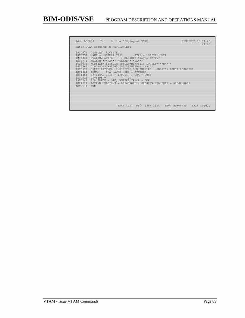
BIM-ODIS/VSE PROGRAM DESCRIPTION AND OPERATIONS MANUAL
VTAM - Issue VTAM Commands Page 89
Addr 000000 (3 ) Online DISplay of VTAM BIMCICST 06:34:40 V1.7GEnter VTAM command: D NET,ID=TR61
IST097I DISPLAY ACCEPTEDIST075I NAME = USBIM01.TR61 , TYPE = LOGICAL UNITIST486I STATUS= ACT/S , DESIRED STATE= ACTIVIST977I MDLTAB=***NA*** ASLTAB=***NA***IST861I MODETAB=ISTINCLM USSTAB=BIMUSSTS LOGTAB=***NA***IST934I DLOGMOD=SNX32702 USS LANGTAB=***NA***IST597I CAPABILITY-PLU INHIBITED,SLU ENABLED ,SESSION LIMIT 00000001IST136I LOCAL SNA MAJOR NODE = ATCTOK6IST135I PHYSICAL UNIT = TRPU06 , CUA = 0086IST082I DEVTYPE = LUIST654I I/O TRACE = OFF, BUFFER TRACE = OFFIST171I ACTIVE SESSIONS = 0000000001, SESSION REQUESTS = 0000000000IST314I END
PF4: CSA PF5: Task list PF6: Hex+char PA2: Toggle

BIM-ODIS/VSE PROGRAM DESCRIPTION AND OPERATIONS MANUAL
Page 90 WATCH - Start or Stop Watchdog Mode
WATCH - Start or Stop Watchdog Mode
This is not a display of any table. It is used to start and stop Watchdog mode.Watchdog mode is started by entering:
ODIS WATCH mmss
Where mmss is the time interval in minutes and seconds. Leading zeroes may beomitted. If a time interval is not specified, the value specified by the WATINTparameter of the ODISOPT macro is used. Watchdog mode is turned off byentering:
ODIS WATCH OFF
This feature may be secured by specifying a SECTRAN in the ODISOPT macro.
It is possible to determine if The Watchdog is active by using the ICE display.When active there will be an entry whose DATA ID is ODISWDOG.
Watchdog mode is fully described in the section “Watchdog Mode” starting onpage 106.
Addr 000000 (3 ) Online DISplay of WATCH 0200 BIMCICST 06:45:03 V1.7G
The Watchdog has been started
PF4: CSA PF5: Task list PF6: Hex+char PA2: Toggle
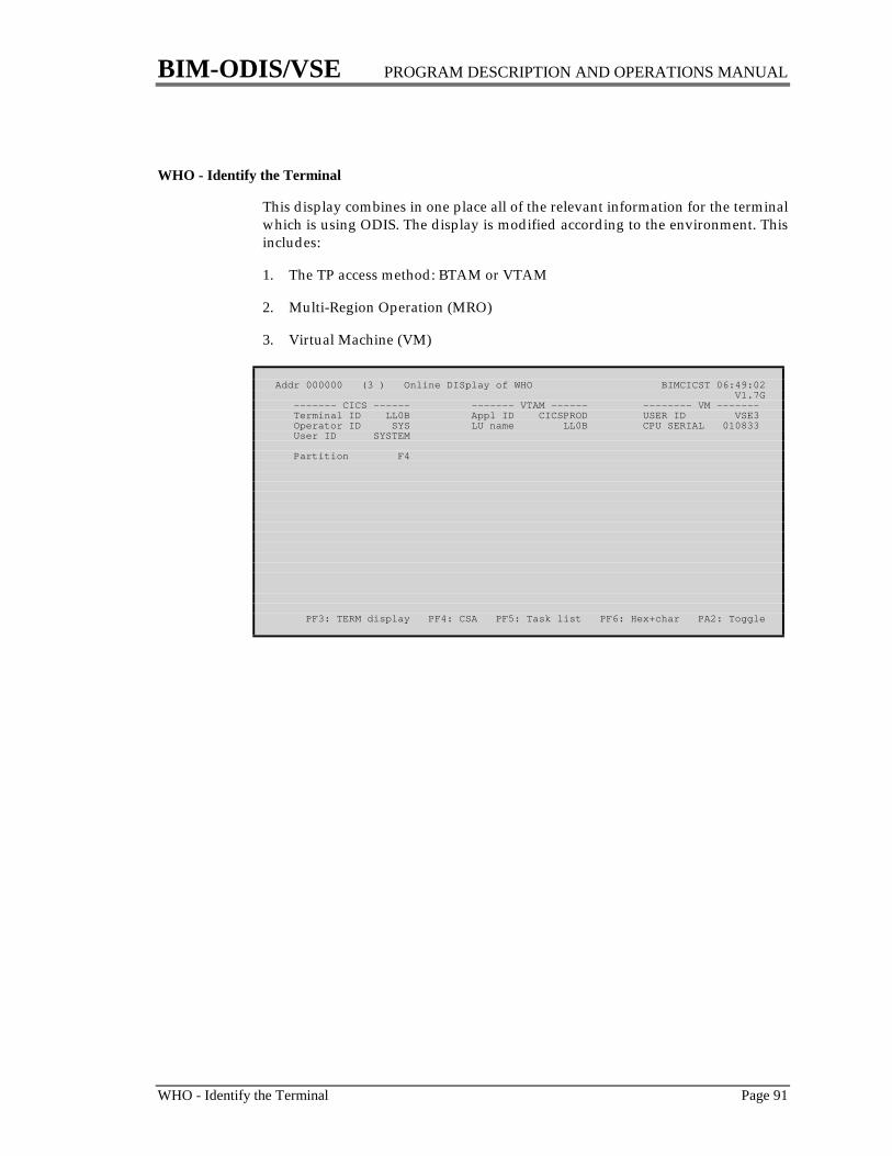
BIM-ODIS/VSE PROGRAM DESCRIPTION AND OPERATIONS MANUAL
WHO - Identify the Terminal Page 91
WHO - Identify the Terminal
This display combines in one place all of the relevant information for the terminalwhich is using ODIS. The display is modified according to the environment. Thisincludes:
1. The TP access method: BTAM or VTAM
2. Multi-Region Operation (MRO)
3. Virtual Machine (VM)
Addr 000000 (3 ) Online DISplay of WHO BIMCICST 06:49:02 V1.7G ------- CICS ------ ------- VTAM ------ -------- VM ------- Terminal ID LL0B Appl ID CICSPROD USER ID VSE3 Operator ID SYS LU name LL0B CPU SERIAL 010833 User ID SYSTEM
Partition F4
PF3: TERM display PF4: CSA PF5: Task list PF6: Hex+char PA2: Toggle

BIM-ODIS/VSE PROGRAM DESCRIPTION AND OPERATIONS MANUAL
Page 92 Storage Display and Alteration
Storage Display and AlterationODIS provides the ability to access storage anywhere in the machine inhexadecimal and character format. This includes the Supervisor, real partitions,virtual partitions and the SVA. The following functions are available.
1. display storage
2. alter storage
3. scan storage
Storage Display
A hexadecimal and character display of storage may be initiated in any of thefollowing ways:
1. Enter a 1-8 digit hexadecimal address as the “table” name. Leading zeroesare not necessary. This may optionally be followed by an address spacenumber or partition id. See “Current Address Space” on page 93.
2. Enter a 1-7 digit displacement preceded by a plus or minus sign as the“table” name. The displacement is added to the current address.
3. Enter a static or dynamic partition ID such as F1, BG, G1, etc. to display thebeginning address of the specified partition. This will also set the “currentaddress space”, as discussed below, to the address space containing thespecified partition.
4. Hitting the PF6 or PF18 key at any time will display the storage beginning atthe address in the upper left hand corner of the screen. The PF6 and PF18keys may be changed for an installation by the ODISOPT macro.
5. Some displays (for example PROG) use PF3 or PF15 to initiate a hexadecimaland character display related to the contents of the screen.
6. The abbreviation of an area of storage may be entered. Select from the list inthe section “Symbolic Unformatted Displays” on page 20.
When a hexadecimal and character display is initiated by one of the abovemethods (except number 2) ODIS remembers the address. This is called the“initial” address and is used for the PF2 or PF14 key.
BIM-ODIS/VSE PROGRAM DESCRIPTION AND OPERATIONS MANUAL
Storage Display and Alteration Page 93
Addr 01A00000 (3 ) Online DISplay of BIMCICST 09:40:05 V1.7G
+00000 01A00000 47F0F110 01261EC9 D1C2C3D5 E2C6C96B *.01....IJBCNSFI,* +00010 01A00010 F9F561F0 F361F3F1 6BF1F5C3 60C4E8F0 *95/03/31,15C-DY0* +00020 01A00020 F0F0F0F0 40F5F6F8 F660F0F6 F6404DC3 *0000 5686-066 (C* +00030 01A00030 5D40C396 97A89989 8788A340 C9C2D440 *) Copyright IBM *
+00040 01A00040 C3969997 4B40F1F9 F9F46B40 F1F9F9F4 *Corp. 1994, 1994* +00050 01A00050 4B40C193 9340D989 8788A3A2 40D985A2 *. All Rights Res* +00060 01A00060 8599A585 844B40E4 E240C796 A5859995 *erved. US Govern* +00070 01A00070 948595A3 40E4A285 99A240D9 85A2A399 *ment Users Restr*
+00080 01A00080 8983A385 8440D989 8788A3A2 406040E4 *icted Rights - U* +00090 01A00090 A2856B40 84A49793 898381A3 89969540 *se, duplication * +000A0 01A000A0 96994084 89A28393 96A2A499 85409985 *or disclosure re* +000B0 01A000B0 A2A39989 83A38584 4082A840 C7E2C140 *stricted by GSA *
+000C0 01A000C0 C1C4D740 E2838885 84A49385 40C39695 *ADP Schedule Con* +000D0 01A000D0 A3998183 A340A689 A38840C9 C2D440C3 *tract with IBM C* +000E0 01A000E0 9699974B 40D38983 8595A285 8440D481 *orp. Licensed Ma* +000F0 01A000F0 A3859989 8193A240 6040D799 96978599 *terials - Proper*
PF1: Forward PF2: Initial PF3: Backward / 24-bit PF4: CSA PF5: Task list
Whenever a hexadecimal and character screen is displayed the PF keys have thefollowing meaning:
PF1 and PF13 advance forward by the number of bytes displayed on one screen(which will vary with the terminal model)
PF2 and PF14 reset the display to the “initial” address
PF3 and PF15 move the display backward by the number of bytes on one screen
PF6 and PF18 reset the “initial” address to the address in the upper left handcorner of the screen (as is done for all of the ODIS displays). Thisresults in the displacements being reset without changing theaddress being displayed.
The ability to display storage may be secured by specifying SECHEX=YES andSECTRAN=xxxx in the ODISOPT macro.
Current Address Space
All entered addresses are assumed to be in the “current address space”, whichnormally is the address space in which ODIS is executing. The current addressspace is displayed following the current address on the top line of screen, “(3 )”in the above example. If the current address space is a dynamic partition, thepartition ID is displayed, such as (G1). You can switch to a different addressspace using any of the following methods:
1. Enter the ID of a partition in the desired address space.
2. Enter the ID of the address space following the address:
100078 1 (This will display address 100078 in address space 1.)100078 3 (This will display address 100078 in address space 3.)
3. Enter the ID of a partition within the desired address space following theaddress:
BIM-ODIS/VSE PROGRAM DESCRIPTION AND OPERATIONS MANUAL
Page 94 Storage Display and Alteration
100078 BG (This will display address 100078 in address spacecontaining static partition BG.)
100078 G1 (This will display address 100078 in address spacecontaining dynamic partition G1.)
Once you change the “current address space”, all storage displays, alterations,and SCANs will occur in the new address space.
When you request the next CICS or VSE table to be displayed, the “currentaddress space” will revert back to the one in which ODIS is executing.
Cursor Positioning
After a hexadecimal and character screen has been displayed anotherhexadecimal and character screen may be selected by simply positioning thecursor and hitting the enter key. This may be done in one of two ways:
1. Position the cursor beneath any portion of an address in the hexadecimalportion of the display. For this purpose an address is defined as a four bytefield (eight hexadecimal digits) which begins on a full word boundary(xxxxx0, xxxxx4, xxxxx8 or xxxxxC). The top byte of the address is ignored.The next display will begin at the selected address.
2. Position the cursor in column one of any row. The next display will begin atthe selected line.
If the cursor is positioned at an unsupported screen location it will be ignored,and the same display will be repeated.
Storage Alteration
When running on a 3270 terminal any area of storage which can be displayed inhexadecimal and character can also be modified in hexadecimal and/orcharacter. This includes the Supervisor, all partitions and the SVA. Because of therisks involved with storage alteration this function may be secured by specifyinga SECTRAN parameter in the ODISOPT macro.
Before an area of storage can be altered it must be displayed. It may then bealtered by simply moving the cursor to the desired location(s) on the screen andmaking the alteration(s) in hexadecimal and/or character. Any amount of data,from one byte to the capacity of the screen, can be altered in this manner. Thesmallest amount of data that can be altered is one byte. When altering data on the“character” part of the screen (right hand side), be sure to enter the data in theintended case, since lower case data will not be translated by ODIS to upper case.
While this feature can be as dangerous as it is useful, a number of safeguardshave been included to make it as safe as possible. Storage will be altered only ifall of the following conditions are met:
1. The transaction ID matches that in the SECTRAN parameter of the ODISOPTmacro if specified.

BIM-ODIS/VSE PROGRAM DESCRIPTION AND OPERATIONS MANUAL
Storage Display and Alteration Page 95
2. No characters on the screen have been deleted (by the DEL, ERASE EOF orERASE INPUT keys)
3. The addresses in the left hand column on the screen have not been altered.
4. The table name at the top of the screen has been left unchanged (i.e. blank)
5. The ENTER key was hit, not a PA or PF key.
For those desiring an exact description of the method of operation the followingdescription is included. This will only be important when dealing with volatiledata. First of all, there are three versions of the area of storage:
1. The “old” version as originally displayed on the screen2. The “new” version on the screen as altered by the terminal operator3. The “current” version as it exists at any moment in storage
ODIS compares the “old” and “new” versions on a byte by byte basis inhexadecimal and character and performs the following:
1. If the “old” and “new” versions are identical (in both hexadecimal andcharacter) the “current” version of the byte is left unchanged.
2. If the “old” and “new” versions are different (in either hexadecimal orcharacter) the “current” version is altered to the new version.
3. After all bytes on the screen have been processed, the “current” version isdisplayed.
The net result of this method is that bytes altered by the terminal user will bealtered by ODIS. Bytes not altered by the terminal user will not be altered byODIS; they may, however, have been altered by VSE or another programbetween the time the data was displayed and the time the terminal operatorrequested the alteration.
Storage alteration is a facility which should be used with care, and its use shouldbe restricted to those who know the details about the area of storage (CICS,Supervisor, VSAM, database, user program, etc.) being altered. The following is apartial list of uses for this feature:
1. modifying assembler programs without reassembly
2. modifying an instruction in a program which causes it to abend at aparticular point during its execution and produce a dump for debuggingpurposes
3. modifying WORKING-STORAGE in a command level COBOL program(This may be located by the DSA ADDR in the TERM display or by using the“WS” special name)
4. making minor changes to CICS tables such as TWA SIZE on the TRANdisplay or NEXT TRANSID on the TERM display
5. modifying instructions or data in batch partitions/regions
BIM-ODIS/VSE PROGRAM DESCRIPTION AND OPERATIONS MANUAL
Page 96 Storage Display and Alteration
6. applying emergency APARs to the Supervisor without performing an IPL
7. changing ASSGNs which were specified incorrectly when CICS was started
The LOGSA parameter of the ODISOPT macro may be used to instruct ODIS tolog all storage alterations to the system console or to a Transient Data destination.
Storage Scan
Use of this feature is documented in the section “SCAN - Scan Storage” startingon page 60.
BIM-ODIS/VSE PROGRAM DESCRIPTION AND OPERATIONS MANUAL
The ODISTRAK Feature Page 97
The ODISTRAK FeatureODISTRAK is a special feature where ODIS records the major CICS statistics andperiodically writes them to a VSAM file. Later, batch reports may be run usingthis data. After initiation, ODISTRAK runs independently of other ODIStransactions. The data may be archived to tape for historical purposes. Use ofODISTRAK requires the following preparatory work:
1. DEFINE the file using IDCAMS2. Add an entry to the FCT3. Select a time interval to be used between successive writes to the file4. Select a frequency at which the ODISTRK file is to be archived to tape5. Select a method to start and stop ODISTRAK
ODISTRAK File Definition
The file used by ODISTRAK is a standard VSAM ESDS file. It should beDEFINEd by running an IDCAMS job similar to the following:
// EXEC IDCAMS,SIZE=AUTO DEFINE CLUSTER( - NAME(ODISTRAK.ESDS) - CISZ(4096) - NONINDEXED - RECORDS(pppp ssss) - RECSZ (1000 2000) - REUSE - SHR(2) - VOL (VOLSER)) - DATA(NAME(ODISTRAK.DATA)) - CATALOG(xxxxxxxxxxxx))/*
A file size of 5-20 cylinders or 5,000 - 20,000 FBA blocks is usually sufficient.Secondary allocation is recommended. A more precise estimate of the file sizeinvolves the following factors:
1. The number of records written at one time. This will be the sum of:one record for every 247 destinationsone record for every 31 filesone record for every 139 programsone record for every 98 terminalsone record for every 66 transactionsone record for every Watchdog message (if any)one record for overall system information
BIM-ODIS/VSE PROGRAM DESCRIPTION AND OPERATIONS MANUAL
Page 98 The ODISTRAK Feature
2. The time interval between successive writes to the file (see below).
3. The frequency at which the file is to be archived to tape, at which time the fileon disk is cleared.
After the file has been DEFINEd, an entry similar to the following should beadded to the FCT:
DFHFCT TYPE=DATASET, X DATASET=ODISTRK, X ACCMETH=(VSAM,ESDS), X SERVREQ=(ADD,REUSE), X STRNO=1, X BUFND=2
Additional data buffers may be allocated if desired.
Selection of Time Intervals
The TRKINT parameter of the ODISOPT macro controls the interval at whichrecords are written. Since ODISTRAK is intended to be used to measure long-term activity, a medium to large interval such as the default value of 15 minutes,should be appropriate under most circumstances. A smaller value may be usedfor more precise timings, but this increases the overhead of writing the recordsand increases the amount of disk space required.
The statistics recorded by ODISTRAK should be retained on disk for a reasonablelength of time and then purged or archived to tape. While this may be done asfrequently as once per CICS startup, a longer period, such as once per week maybe more convenient from an operational viewpoint.
Starting ODISTRAK
When initially testing ODISTRAK, it may be started and stopped manually byusing the TRAK ON and TRAK OFF functions. For long term production use,however, ODISTRAK should probably be started automatically by using a PLT.Instructions for doing so are documented in the section “CICS Table Entries”starting on page 6. The PLTPI paramter of the ODISOPT table must include avalue of TRAK. Also, if a nonstandard transaction ID is to be used, theTRKTRAN parameter must be specified accordingly.
Batch Report JCL
Batch reports may be produced by running a job step similar to the following:

BIM-ODIS/VSE PROGRAM DESCRIPTION AND OPERATIONS MANUAL
The ODISTRAK Feature Page 99
// DLBL ODISTRK,'ODISTRAK.ESDS',,VSAM,CAT=xxxxxxx// ASSGN SYS001,DISK,...// DLBL SORTWK1,...// EXTENT SYS001,...// EXEC ODISTRAK,SIZE=(ODISTRAK,64K) parameter cards/*
If the CICS system associated with the file is running, then ODISTRAK should beturned off with the TRAK function and the ODISTRK file should be closed beforethe report step is run. If the ODISTRK file is still open, the reports will probablyomit numerous records that are not yet reflected in the VSAM catalog.
Stopping ODISTRAK
In order to minimize data lost during the last interval prior to CICS shutdownODISTRAK should be included in a shutdown PLT. Instructions for doing so aredocumented in the section “CICS Table Entries” starting on page 6.
Parameter Card Syntax
Parameter cards must observe the folowing conventions:
1. An asterisk in column 1 indicates a comment card.
2. The keyword (such as REPORT) may be preceded by one or more spaces andmust be followed by one or more spaces.
3. The parameters must have no imbedded spaces.
4. Parameters and values are terminated by a space. Comments may follow.
5. Only columns 1 - 72 are examined. Columns 73 - 80 are ignored.
6. Cards cannot be continued.
Parameter Cards
The RANGE card indicates which records from the input file are to be used whenproducing the reports indicated by subsequent REPORT cards. The format is:
RANGE START=(MM/DD/YY,HH:MM:SS),END=(MM/DD/YY,HH:MM:SS)
The default for START and END are the first and last records in the file. The timespecification in each case is optional. START defaults to 00:00:00 and ENDdefaults to 23:59:59.
The REPORT card indicates which report(s) are to be produced. There is nodefault. The format is:
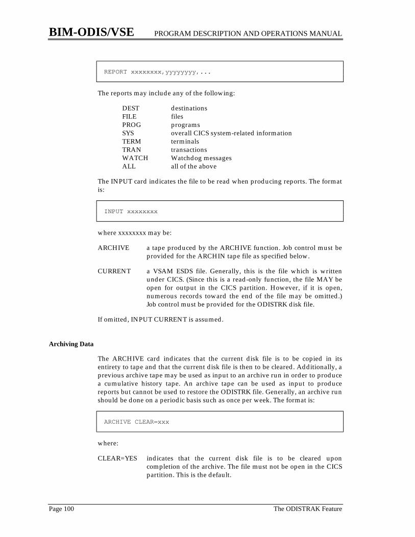
BIM-ODIS/VSE PROGRAM DESCRIPTION AND OPERATIONS MANUAL
Page 100 The ODISTRAK Feature
REPORT xxxxxxxx,yyyyyyyy,...
The reports may include any of the following:
DEST destinationsFILE filesPROG programsSYS overall CICS system-related informationTERM terminalsTRAN transactionsWATCH Watchdog messagesALL all of the above
The INPUT card indicates the file to be read when producing reports. The formatis:
INPUT xxxxxxxx
where xxxxxxxx may be:
ARCHIVE a tape produced by the ARCHIVE function. Job control must beprovided for the ARCHIN tape file as specified below.
CURRENT a VSAM ESDS file. Generally, this is the file which is writtenunder CICS. (Since this is a read-only function, the file MAY beopen for output in the CICS partition. However, if it is open,numerous records toward the end of the file may be omitted.)Job control must be provided for the ODISTRK disk file.
If omitted, INPUT CURRENT is assumed.
Archiving Data
The ARCHIVE card indicates that the current disk file is to be copied in itsentirety to tape and that the current disk file is then to be cleared. Additionally, aprevious archive tape may be used as input to an archive run in order to producea cumulative history tape. An archive tape can be used as input to producereports but cannot be used to restore the ODISTRK file. Generally, an archive runshould be done on a periodic basis such as once per week. The format is:
ARCHIVE CLEAR=xxx
where:
CLEAR=YES indicates that the current disk file is to be cleared uponcompletion of the archive. The file must not be open in the CICSpartition. This is the default.

BIM-ODIS/VSE PROGRAM DESCRIPTION AND OPERATIONS MANUAL
The ODISTRAK Feature Page 101
CLEAR=NO indicates that the current disk file is to be left unchanged by thearchive. The file may be open in the CICS partition, but if so,numerous records near the end of the file will be omitted fromthis run.
Job control must specify:
1. A TLBL for an old archive tape named ARCHIN and an ASSGN for SYS004.If an input tape is not to be used, assign SYS004 to IGN.
2. A TLBL for a new archive tape named ARCHOUT and an ASSGN forSYS005. If no output tape is desired, assign SYS005 to IGN.
Report Format
The title of each report includes the following information:
1. The date and time of first and last records encountered within the rangespecified.
2. The number of intervals observed within the range specified.
3. The VTAM application ID except under certain circumstances when it isunavailable.
Under certain circumstances for the System and Watchdog reports the aboveinformation will appear at the bottom of the report.
Specific comments concerning some of the information shown on these reportsappears following the sample reports.
Sample Reports
Destinations
ODISTRAK V1.7G HISTORICAL DESTINATION DATA FROM 08/02/94 22:07:36 REPORT PRODUCED 01/08/95 22:14:23 PAGE 1 CICSPROD TO 08/09/94 21:26:22 BASED UPON 44 INTERVALS DEST WRITES DEST WRITES DEST WRITES DEST WRITES DEST WRITES DEST WRITES DEST WRITES DEST WRITES
CPLD 0 CPLI 0 CSML 0 CSMT 174 CSSL 546 CSSM 0 CSSN 0 CSTL 372 L86P 0 RCLG 0 RCPH 0TOTAL 1,092

BIM-ODIS/VSE PROGRAM DESCRIPTION AND OPERATIONS MANUAL
Page 102 The ODISTRAK Feature
Files
ODISTRAK V1.7G HISTORICAL FILE DATA FROM 08/02/94 22:07:36 REPORT PRODUCED 01/08/95 22:14:23 PAGE 1 CICSPROD TO 08/09/94 21:26:22 BASED UPON 44 INTERVALS GET --STR WAIT-- --BUFF WAIT-- FILE READ ADD UPDATE UPDATE BROWSE DELETE TOTAL HIGH TOTAL HIGH TOTAL
FMAPFLE 0 0 8 8 0 0 8 ODISTRK 0 324 0 0 0 0 324 ONLMSGS 0 0 0 0 19 0 19 STAGER 0 0 0 0 0 0 0 TOTALS 0 324 8 8 19 0 351 0 0 0 0
Programs
ODISTRAK V1.7G HISTORICAL PROGRAM DATA FROM 08/02/94 22:07:36 REPORT PRODUCED 01/08/95 22:14:23 PAGE 1 CICSPROD TO 08/09/94 21:26:22 BASED UPON 43 INTERVALS PROGRAM USED FETCH PROGRAM USED FETCH PROGRAM USED FETCH PROGRAM USED FETCH
BIMCMDR 2 2 BIMCNDEF 19,628 2 BIMCNEXT 217 2 BIMCNSOL 19,646 2 BIMCSDT 2 2 BIMCSED 0 0 BIMCSPS 1,269 2 BIMCSTAT 0 0 BIMCXDEF 2 2 BIMCXENA 2 2 BIMCXTCP 2 2 BIMDEVC 0 0 BIMDPWR 36 1 BIMECHO 0 0 BIMECHOC 47 2 BIMECHOI 2 2 BIMECHOX 2 2 BIMECHO1 0 0 BIMECHO2 0 0 BIMEXDIS 0 0 BIMEXENA 0 0 BIMGETSP 4 2 BIMGMM17 61 2 BIMLIBTB 1 1 BIMMNDEF 4 2 BIMMNTR 31 1 BIMPRDEF 3 2 BIMPRINT 0 0 BIMPXENA 2 2 BIMPXICP 4 2 BIMP3270 0 0 BIMSERV 2 1 BIMSMS 0 0 BIMSNDEF 1 1 BIMSPCTL 33 1 BIMSPDEF 23 2 BIMSPEXT 26 1 BIMSPINT 2 2 BIMSPLSR 25 1 BIMSPLXT 0 0 BIMSPMSG 60 2 BIMSPOON 0 0 BIMSPPRT 5,063 2 BIMSUBMT 0 0 BIMSWAP 0 0 BIMSWAPM 0 0 BIMSWAPP 2 2 BIMSWAPX 2 2 BIMTEST1 0 0 BIMVTCMD 344 2 CMPRDRIV 0 0 DFHACP 23 2 DFHEIGDS 0 0 DFHEITAB 0 0 DFHEITMT 13 2 DFHEITOT 0 0 DFHEITSP 0 0 DFHEITST 0 0 DFHEMA 0 0 DFHEMB 18 2 . . . IBMFPGDA 0 0 IBMFPMRA 0 0 IBMFSTVA 0 0 ODIS 96 3 ODISOPT 3 2 TOTALS 47,576 109
System
ODISTRAK V1.7G HISTORICAL CICS SYSTEM DATA FROM 08/02/94 22:07:36 REPORT PRODUCED 01/08/95 22:14:23 PAGE 1STARTUP 08/02/94 21:17:17 CICSPROD TO 08/09/94 21:26:22 BASED UPON 43 INTERVALS TOTAL TIMES PROG DUMPS R'WAY TIMES STG DSA WDOG TSMAIN PUT(Q) PUT(Q) DATE TIME TASKS MXT CHECKS TAKEN TASKS SOS VIO FREE GETMAIN MSGS IN USE MAIN AUX
08/02/94 22:07:36 0 0 0 0 0 0 0 1056K 0 0 K 0 0 08/02/94 22:08:00 2 0 0 0 0 0 0 1068K 43 0 K 1 2 08/02/94 22:10:00 12 0 1 1 0 0 0 1056K 134 0 K 1 7 . . . 08/02/94 22:38:00 17 0 2 2 0 0 0 1056K 89 0 K 1 7 08/02/94 22:40:00 8 0 0 0 0 0 0 1056K 92 0 K 1 7 TOTAL OF ABOVE 141 0 3 3 0 0 0 1,685 0 19 114 ENDING VALUE 335 0 3 3 0 0 0 1056K 7,784 K 22 262 MAXIMUM VALUE 13 0 2 2 0 0 0 1068K 167 0 K 2 7
The fields shown on the system report fall into two categories. The followingfields are snapshots which show the value of the field at the time shown:
DSA FREETSMAIN IN USE
These fields will be blank in the total lines.

BIM-ODIS/VSE PROGRAM DESCRIPTION AND OPERATIONS MANUAL
The ODISTRAK Feature Page 103
All other fields show the number of times an event occurred within the interval.The time shown is that of the end (not the beginning) of the interval.
Terminals
ODISTRAK V1.7G HISTORICAL TERMINAL DATA FROM 08/02/94 22:07:36 REPORT PRODUCED 01/08/95 22:14:23 PAGE 1 CICSPROD TO 08/09/94 21:26:22 BASED UPON 16 INTERVALS TRANS --- MESSAGES --- XMIT STG TRANS --- MESSAGES --- XMIT STG TRANS --- MESSAGES --- XMIT STG TERM ACTIONS INPUT OUTPUT ERRS VIO TERM ACTIONS INPUT OUTPUT ERRS VIO TERM ACTIONS INPUT OUTPUT ERRS VIO
BMDY 0 0 0 0 BM01 0 0 0 0 BM02 0 0 0 0 BM1A 0 0 0 0 BM1B 0 0 0 0 BM1X 0 0 0 0 BM1Y 0 0 0 0 BM1Z 0 0 0 0 CNSL 2 4 2 0 DADY 0 0 0 0 DA02 281 14 24 0 DA04 4,815 0 71 0 1 . 0 . 0 . 0 LL7A 49 357 354 0 LL7B 0 0 1 1 TS01 0 0 0 0 TS1A 0 161 298 24 TS1B 0 27 35 8 TS1C 0 3 368 8 TS1W 0 0 0 0 TS1X 0 0 0 0 TS1Y 0 0 0 0 TS1Z 0 0 0 0 WA01 0 428 845 0TOTAL 5,858 1,922 21,846 57 1
Transactions
ODISTRAK V1.7G HISTORICAL TRANSACTION DATA FROM 08/02/94 22:07:36 REPORT PRODUCED 01/08/95 22:14:23 PAGE 1 CICSPROD TO 08/09/94 21:26:22 BASED UPON 44 INTERVALS RE STALL STG RE STALL STG RE STALL STG TRAN USED START PURGE VIO TRAN USED START PURGE VIO TRAN USED START PURGE VIO
$ATT 0 $BIM 0 PF10 0 PF11 0 PF12 0 BCST 0 BIMC 0 BIMP 0 BMGM 62 . . . LOG2 0 MNTR 31 MSG 1 ODIS 42 POWC 33 POWM 0 RXLS 0 SERV 2 SPOL 5,068 2 SWAP 0 SWAX 3 TEST 0 VCMD 342 XDIS 0 XENA 0 PF1 0 PF4 0 PF5 0 PF6 12 PF7 0 PF8 0 PF9 0 TOTALS 12,879 0 0 2
Watchdog
ODISTRAK V1.7G HISTORICAL WATCHDOG DATA REPORT PRODUCED 01/08/95 14:24:07 PAGE 1STARTUP 01/07/95 09:41:48 CICSPROD PROBLEM DATE TIME NUMBER IMPACTS DESCRIPTION OF PROBLEM
01/07/95 10:02:15 18 SYSTEM TRAN CEMT AT TERM LL0B USING TOO MUCH (39K) STORAGE 01/07/95 11:25:00 61 SYSTEM ***** STORAGE VIOLATION HAS OCCURRED ***** DATA FROM 01/07/95 19:44:28 TO 01/08/95 14:22:28 BASED UPON 36 INTERVALS
This report shows all Watchdog messages which have not been suppressed bythe WATSUPR parameter of the ODISOPT macro. It is unaffected by theLOGWAT and WATTERM parameters.
BIM-ODIS/VSE PROGRAM DESCRIPTION AND OPERATIONS MANUAL
Page 104 The ODISTRAK Feature
Resetting Statistics
ODISTRAK attempts to detect the resetting of statistics which occurs when theCSTT AOC transaction is executed. Whenever this occurs, there will probably besome activity which cannot be recorded by ODISTRAK.

BIM-ODIS/VSE PROGRAM DESCRIPTION AND OPERATIONS MANUAL
Time-Initiated Mode Page 105
Time-Initiated ModeWhen running on a 3270 terminal, any of the ODIS displays may beautomatically redisplayed by ODIS at regular time intervals, without requiringany action by the operator. To do this, first display the desired screen. Then,modify either the table name or the entry name to one of the following:
T=mmssT=mssT=ssT=s
to specify the time interval in minutes and seconds. To indicate that ODIS isautomatically refreshing the display, the top line of the screen will have the timeinterval added.
The minimum time interval can be controlled using the TIMMIN parameter ofthe ODISOPT customization macro. Refer to page 11 for more information.
During time-initiated mode the 3270 entry keys may be used as follows:
1. The enter key redisplays the screen immediately and remains in time-initiated mode.
2. The clear key terminates ODIS.
3. Any other key terminates time-initiated mode but leaves ODIS running at theterminal.
In Multi-Region Operation (MRO) environment, time-initiated mode is notpossible if the ODIS transaction is being routed by CRTE, but is possible if theODIS transaction is explicitly routed by its own entry in the PCT.
BIM-ODIS/VSE PROGRAM DESCRIPTION AND OPERATIONS MANUAL
Page 106 Watchdog Mode
Watchdog ModeWatchdog mode is a method of operation where ODIS is periodically invoked toexamine the CICS system and look for potential problems. If any problems aredetected they will be reported at a CICS terminal; if no problems are detectedthere will be no messages. Thus, Watchdog mode reports on an exception basis.The Watchdog is capable of writing its messages to one or two locationsaccording to the specifications in the ODISOPT macro:
1. A CICS terminal, such as the operator's console as specified by theWATTERM parameter.
2. The operator's console (LOGWAT=YES) or a Transient Data destination(LOGWAT=XXXX).
The preferred, and default method of operation is to run as a nonterminal-oriented transaction with the output directed to the operator's console. If aterminal is selected by the WATTERM parameter, The Watchdog will be madesubject to the availability of that terminal.
The Watchdog runs just like any other CICS transaction. However, its operationis restricted in two ways:
1. It never issues a read to the terminal. This allows The Watchdog to run on aprinter.
2. It may not issue any I/O to the terminal, that is, it will only do I/O if anexception condition occurs.
The potential problems which are reported are those detected by the PROBdisplay except for those with a severity of NOTE (which are generally historicalmessages that do not indicate a current problem). The Watchdog transaction is astandard CICS transaction; therefore it is subject to all of the restrictions imposedupon CICS transactions including the following:
The AMAX and MAXT limits must not be reached.The system must not be short on storage.
If a terminal is specified by the WATTERM parameter, the following additionalrestrictions apply:
The terminal must be in service.The terminal's control unit (if any) must be in service.The terminal's line (non-VTAM) must be in service.A transaction must not be running at the terminal.The terminal's security key must match the transaction security key (if any)defined in the PCT for ODIS.
BIM-ODIS/VSE PROGRAM DESCRIPTION AND OPERATIONS MANUAL
Watchdog Mode Page 107
In addition to the problems detected by the PROB feature, The Watchdog is ableto detect the occurrence of some of the above problems during the intervalbetween executions of The Watchdog. In this case the message will indicate thetime The Watchdog detected the problem, which is not necessarily the time theproblem occurred.
The time interval selected determines how often The Watchdog is invoked. A lowinterval allows The Watchdog to detect more transient problems but increases theoverhead associated with The Watchdog. Since this overhead is relatively small alow time interval may be selected at times when problems are expected. Forgeneral use a time interval of approximately two minutes is recommended.
It is highly recommended that The Watchdog by automatically initiated whenCICS is started. This may be done in one of two ways:
1. in a CRLP terminal as documented in the section “MiscellaneousConsiderations” on page 132.
2. by including ODIS in a Program List Table during program initialization.This requires the following CICS table entries:
DFHPLT TYPE=ENTRY,PROGRAM=ODISDFHPPT TYPE=ENTRY,PROGRAM=DFHPLTxxDFHSIT PLTPI=xx
In this case the default time interval (two minutes) will be used. This may bechanged later, if desired, by issuing the WATCH command with the desiredtime interval.
Use of this feature may be restricted by specifying a SECTRAN in the ODISOPTmacro.
Message Suppression
The Watchdog normally issues messages for all problems with a severity ofLOW, MED, or HIGH (but not those with a severity of NOTE). However, at someinstallations certain conditions which ODIS considers to be potential problemsmay be considered by the installation to be normal. The Watchdog may bedirected to suppress the messages for such conditions, either permanently ortemporarily, as follows:
1. To permanently suppress a message specify the message number in theWATSUPR parameter of the ODISOPT macro.
2. To temporarily suppress a message execute an ODIS transaction using the“table” name of DISABL and the “entry” name as the number of the problemto be suppressed, for example:
ODIS DISABL 17

BIM-ODIS/VSE PROGRAM DESCRIPTION AND OPERATIONS MANUAL
Page 108 Watchdog Mode
At a future point in time the message may be allowed by entering:
ODIS ENABLE 17
The ENABLE and DISABL functions may also be used to override thespecifications of the WATSUPR parameter of the ODISOPT macro.
Watchdog User Exits
In order to allow the installation to customize the operation of The Watchdog twouser exits are provided. These are standard CICS Command Level assemblerprograms. If used, they must be included in the PPT in the same manner as allother CICS programs. The parameters of the DFHPPT macro may be chosen inany manner desired by the installation, although RES=YES is recommended.
ODIS LINKs to the first user exit at the start of each execution of The Watchdog.This exit may perform any of its own checks for special conditions and may issueits own messages to the terminal. This exit is selected by specifyingWATXIT1=xxxxxxxx in the ODISOPT macro.
ODIS LINKs to the second user exit prior to writing each message issued by TheWatchdog. This exit may examine the message, change the text of the message orsuppress writing of the message entirely. If a message has been suppressed bythe WATSUPR parameter of the ODISOPT macro it will not be presented to thisuser exit. This exit is selected by specifying WATXIT2=xxxxxxxx in the ODISOPTmacro.
ODIS follows standard CICS linkage conventions. If The Watchdog is running ata terminal, the exit program may issue output to the terminal via any of thestandard CICS methods (e.g. EXEC CICS SEND). Return to ODIS is via thestandard RETURN command. WATXIT1 is entered without a COMMAREA.WATXIT2 is entered with a COMMAREA which contains:
0 message number (a one byte binary field)1-2 message number (a two byte character field)
5-10 “impacts” field: SYSTEM or TASKS13-16 “severity” field: HIGH, MED or LOW19-71 text of message
The message number is the number described with the PROB display. Themessage may be suppressed by changing the binary message number to X'00'.
Some possible uses for user exits are as follows:performing CICS checks beyond those performed by ODISchecking user application systemsconditionally suppressing certain messagesconditionally changing message textsrecording statisticsmonitoring non-IBM softwarecorrecting some problems, for example placing a terminal in service
BIM-ODIS/VSE PROGRAM DESCRIPTION AND OPERATIONS MANUAL
Watchdog Mode Page 109
A sample user exit is provided during installation in source format under thename ODISEXIT.A. This program may be assembled by running a job stepsimilar to:
// LIBDEF SOURCE,SEARCH=lib.sublib// EXEC ASSEMBLY COPY ODISEXIT END/*

BIM-ODIS/VSE PROGRAM DESCRIPTION AND OPERATIONS MANUAL
Page 110 Using ODIS for Problem Determination
Using ODIS for Problem DeterminationOne area where ODIS can be particularily valuable is in problem determination.Generally speaking, the better an understanding the user has of CICS (and VSE)processing the more useful ODIS will prove to be. At the same time a carefulexamination of the tables provided by ODIS can help supply some of thisunderstanding. At all times a familiarity with IBM manuals will prove to bevaluable. While the number of user-related problems is obviously very large andimpossible to document completely, this section illustrates some of the ways thatODIS can help in problem determination.
1. PROBLEM: A terminal is “stuck”; other terminals are able to operatenormally.
PROCEDURE: Begin with the TERM display. Look for OUT OF SERVICE,CU OUT SERVICE, LINE OUT SERVICE or NOT CONNECT VTAM; if oneof these is displayed this is probably the source of the problem. A task shouldbe running; if so, the third column on the screen will be in use. In the TASKdisplay look at the MOD, LAST REQ, DISPATCH CNTL, and RESOURCE tofind the current state of the transaction. For example, if the task is running inKCP and WAIT FOR ENQ the task is waiting for an enqueued resource; lookat the ENQ display to see which task owns the resource. If the task is runningin FCP and waiting for I/O, VSAM strings or buffers, the name of the fileshould be shown. If the task is one of the ACTIVE TASKS it may be in a looprequesting the same CICS service repeatedly; for example, if the task isrunning in TSP check the TS and TSCOM displays to see if the I/O count isincreasing rapidly.
2. PROBLEM: The screen displayed by a transaction is partially scrambled.There seems to be a problem with attribute bytes, SBA sequences, non-display fields, etc.
PROCEDURE: If this is a pseudo-conversational transaction it will probablybe necessary to use the storage alteration facility to modify an instruction sothe program will abend at a potential error location in the program. If this isa true conversational transaction it will stop when it issues a READ to theterminal. At this point any of the TIOAs on the TIOA chain may beexamined. Begin with the TERM display. Either look at the CURRENT TIOAor chase the TIOA chain which begins at FIRST TIOA using the hexadecimaland character display. If the transaction has issued a FREEMAIN for anyTIOAs they cannot be displayed since they no longer exist. The storage freezefunction of the CSFE transaction will cause CICS to ignore all FREEMAINrequests, thus making it possible to view all TIOAs with ODIS. Thistransaction is documented in the CICS Operator's Guide.

BIM-ODIS/VSE PROGRAM DESCRIPTION AND OPERATIONS MANUAL
Using ODIS for Problem Determination Page 111
3. PROBLEM: A transaction is behaving strangely; the programmer would liketo look at WORKING-STORAGE.
PROCEDURE: The only practical time to examine a running transaction iswhile it is in a long term wait such as a ter terminal read. During this wait,begin with the TERM display. To view the transaction's WORKING-STORAGE change the entry name at the top of the screen (which nowcontains the terminal ID) to “WS”. The Data Division map produced by theCOBOL comiler will describe the contents of this area. In a similar mannerthe EIB, TIOAs, TCA and other task-related fields may be displayed. Ifdesired the contents of WORKING - STORAGE may be altered by using thestorage alteration facility.
4. PROBLEM: A whole room full of terminals, all running the same transaction,is “stuck”; terminals running different transactions are operating normally.
PROCEDURE: One task is probably holding a resource required by the othertasks. This is most likely an ENQ or an ECB which represents VSAM stringsor buffers. The PROB display will probably indicate that there are taskswaiting for enqueued resources or that some tasks are waiting for aparticular file. For more detail look at the appropriate ODIS displaymentioned on the right hand side of the screen. For this example, assume thatthe problem lies with an enqueued resource. Use the ENQ display to seewhich terminal owns the resource; all other terminals should be listed aswaiting for the same resource. Use the TERM display to determine the statusof the terminal which owns the resource. In a manner similar to that forproblem 1 above, determine what must be done to cause this transaction tocontinue processing, end, and/or DEQ the resource. In some cases it may benecessary to cancel the task. Once the resource is freed the other tasks at theother terminals should continue normally.
5. PROBLEM: Response time for a particular transaction is erratic. This doesnot seem to be related to any significant variation in work being performed,but seems to depend on the number of terminal operators using thistransaction simultaneously.
PROCEDURE: This is may be caused by insufficient VSAM strings orbuffers. Another alternative would be an enqueued resource; this isdescribed as problem 4 above. Begin with the PROB display (while theproblem is occurring). If ODIS does not detect any potential problems hit theenter key periodically. If this is a problem with VSAM strings or buffers thePROB display will indicate which file is causing the problem. Using the FILEdisplay for the particular file will provide more detail such as the number ofstrings available, number in use and number of tasks waiting. If this is theproblem the number of strings or buffers should probably (but notnecessarily) be increased.
6. PROBLEM: Users are complaining about poor response time.
PROCEDURE: This can be one of the more difficult problems to addressbecause of the many potential causes of poor response time. If only sometransactions are affected some of the other problems described in this section
BIM-ODIS/VSE PROGRAM DESCRIPTION AND OPERATIONS MANUAL
Page 112 Using ODIS for Problem Determination
should be investigated. If all transactions are affected the first course ofaction should be to examine those factors which affect the entire system.These include the CPU usage, paging rate, disk channel utilization and CICSpartition/region priority. A batch performance monitor may be useful inperforming this analysis. Assuming that the problem seems to lie withinCICS and is not caused by an overall system degradation there are a numberof possible approaches. The PROB display will simultaneously check formany potential problems. The various limits (maximum tasks, maximumactive tasks, time intervals, etc.) may be examined with the CSA display. Thestorage-related items (such as short on storage) may be examined with thePAM display. A list of all active and suspended tasks may be displayed withthe TASK display. With a knowledge of the transactions running it may bepossible to detect a high priority transaction that is consuming adisproportionate share of the system's resources. It may be CPU bound orperforming a very long file browse. In this case lowering the transaction'spriority may be a satisfactory way to deal with the situation.
7. PROBLEM: A pseudo-conversational transaction will not stop executing. Nomatter what the terminal operator enters the transaction is reinvoked thuspreventing any other transaction from using the terminal. Furthermore, sinceit is pseudo-conversational, it runs so quickly that there isn't enough time tocancel it.
PROCEDURE: This problem can easily occur when a program that isdesigned to run on a 3270 terminal is run on another terminal. Lacking aclear key, there may be no alternate way of ending the transaction. Beginwith the TERM display for the affected terminal. The NEXT TRANS ID fieldwill contain something other than spaces. Using the displacement for thisfield (currently X'7C') locate it in the hexadecimal and character displayproduced by hitting the PF6 key. Using the storage alteration facility changeit to spaces. The terminal will then be free.
8. PROBLEM: A minor mistake was made in one of the CICS tables. While it ispossible to bring CICS down and up in order to fix the problem it would bebetter to avoid this.
PROCEDURE: Before considering any changes to any tables the risks mustbe assessed. Certain changes, such as changing a transaction's TWA size,may be made very safely. Other changes, such as changing a program'slanguage, may be more difficult and entail some risk. Other changes, such ascompletely replacing a PCT entry, are very difficult and perhaps impossible.Furthermore, anyone modifying internal CICS control blocks shouldunderstand all related factors and must be willing to assume responsibilityfor the consequences. Also, before making any changes, the appropriate CICSdocumentation should be consulted. After the above precautions have beentaken the mechanics of making the change becomes relatively simple. First,display the desired table entry. The displacement displayed with the field isthen used to find the exact location of the field in the associated hexadecimaland character display (which is most easily displayed by using the PF6 key).The change should then be double checked by repeating the formatteddisplay; the PA2 (toggle) key may be used for this purpose.

BIM-ODIS/VSE PROGRAM DESCRIPTION AND OPERATIONS MANUAL
Using ODIS for Problem Determination Page 113
9. PROBLEM: A batch partition seems to be “stuck”.
PROCEDURE: The partition may be waiting for access to a locked resource;if so, the partition will be included in the WAITING portion of the LOCKWAIT display. If this is not the cause of the problem, examine the PARTdisplay for a period of time. If it is executing I/O commands its STARTIOcount will keep increasing. If it is executing CPU instructions its CPU TIMEwill keep increasing. (Note that this field is accurate to the nearest second).Examining bytes 8-15 at the start of the partition will show the PSW, whichshould probably change frequently. The RUN CODE in the PART orCOMREG display will show the dispatching status of the partition. Thesecodes are documented in the Supervisor listing and in the SupervisorDiagnosis Reference manual. A value other than 83 indicates that thepartition is waiting for something. For example, 81 indicates that thepartition is waiting for the LTA; 82 indicates that the program is waiting forI/O to complete. If the RUN CODE is consistently 82 and the CPU TIME andSTARTIO fields remain constant a lost interrupt may be the cause. Todetermine this look at the PUB display, especially for disk devices. Except forTP devices the CHQ field should not remain constant for any length of time.If this field remains constant for a disk device, it is probably due to a lostinterrupt. Unfortunately, there is no satisfactory way to resolve this problem.Cancelling the affected partition should allow the rest of the system tocontinue normally without the need for an IPL. The CHANQ display for theappropriate entry will show which partition is affected. It is likely that otherpartitions have requested the use of this device (if it is a disk) and are alsowaiting for the first partition's I/O to complete. They may be identified byfollowing the CHAIN field. An alternative to cancelling the partition may beto ready the device by turning it off and on, hitting the attention button,“popping the plug”, etc., but if this doesn't work it will probably benecessary to cancel the partition.
10. PROBLEM: A batch partition is running much longer than expected. ThePART display shows that the CPU TIME and STARTIO counts areincreasing, so the program is executing. It is just running too long.
PROCEDURE: Most programs contain some field(s) in WORKING -STORAGE which indicate the progress of the program. This may be a recordcounter, a key, a page number or some similar field. Using a listing of theprogram with a Data Division may and a hexadecimal and character displayof the partition these fields may be located. They may indicate that theprogram is in a loop, is processing more data than expected, or some othersituation. It might also be useful to examine the COMREG display for thepartition and look at the LINES SPOOLED to see if the job is producing toomuch or too little printed output.
11 PROBLEM: The operator has cancelled a batch partition, but it won't come toend of job.
PROCEDURE: If the system is producing a core dump the partition'sCOMREG display will show that the LINES SPOOLED count is increasingrapidly. If so, the dump should finish eventually. In order to produce a coredump and come to end of job the partition must be able to use the LTA. If

BIM-ODIS/VSE PROGRAM DESCRIPTION AND OPERATIONS MANUAL
Page 114 Using ODIS for Problem Determination
another partition is occupying the LTA this could be the cause of the delay.In this case the RUN CODE field for this partition in the PART and COMREGdisplay will be set to 81. The SYSCOM display will show the TASKOWNING LTA and the name of the transient last running in the LTA. Thepartition which owns the LTA is probably waiting for an operator response.Answering the message should allow the affected partition to continue withthe cancellation. Failure to cancel could also be caused by a lost interrupt forthis or another partition. Follow the procedure for problem 7 above.
BIM-ODIS/VSE PROGRAM DESCRIPTION AND OPERATIONS MANUAL
Using ODIS to Analyze Storage Utilization Page 115
Using ODIS to Analyze Storage UtilizationOne of the more important, yet difficult, system-wide CICS facilities to bemanaged is virtual storage. (CICS does not directly manage real storage.) ODISprovides the tools to experimentally determine how CICS is utilizing storage andhow storage should be allocated.
Before discussing how to use ODIS for this purpose it is necessary to discuss themanner in which CICS uses storage. Within the VSE partition CICS is given anamount of storage equal to:
1. the size specified on the EXEC DFHSIP,SIZE=nnnnK statement if CICS is notrun under ICCF
2. the size of interactive partition number zero if CICS is run under ICCF.
During initialization CICS uses most of its storage as a static area for its programsand tables plus resident application programs; the rest of the storage forms theDynamic Storage Area (DSA), which is allocated dynamically as needed. It isused to hold working storage, nonresident programs, Temporary Storage dataand other miscellaneous items. It is this DSA which is a potential source ofproblems.
Dynamic Storage Area
When the unused storage remaining in the DSA drops to a limit, called thestorage cushion, CICS takes steps to increase the amount of available storage inthe DSA. It does this by reusing all storage allocated to all non-resident programswhich are not currently in use. This action does not have immediate, negativeimpact on the operation of the CICS system. However, if CICS is unable toincrease the amount of unused storage above the size of the storage cushion thesystem is said to be short on storage, or SOS (an appropriate acronym). Message:
DFH0506 CICS/VS IS UNDER STRESS - SHORT-ON-STORAGE
will be displayed on the operator console. At this point CICS will not start anynew transactions. If this condition exists for a period of time, called the stallinterval, and if no activity takes place in the CICS system during this period,CICS takes drastic steps to correct the situation. This involves cancellingtransactions defined in the PCT as stall purgeable (SPURGE=YES) until the SOScondition no longer exists. Each time a transaction is cancelled message:
DFH2011 - SYSTEM STRESS, TRANS ID=xxxx, TERM ID=xxxx, ABEND=AKCP
BIM-ODIS/VSE PROGRAM DESCRIPTION AND OPERATIONS MANUAL
Page 116 Using ODIS to Analyze Storage Utilization
is displayed on the operator console. (A stall condition will also occur if thesystem is at the maximum task limit and no activity takes place during the stallinterval.) When the storage cushion is reestablished, message:
DFH0507 CICS/VS IS NO LONGER SHORT-ON-STORAGE
will be displayed on the operator console.
The CICS control block which is used to control the DSA is the Page AllocationMap (PAM). It may be displayed by ODIS using PAM as the table name. Thefollowing fields are useful in determining the size required for the DSA:
PGM PAGES tells how many pages (2048 or 4096 bytes each, depending onoperating system environment), are used for nonresidentprograms which are temporarily resident in virtual storage.
PAGES IN DSA gives the size of the DSA.
CUSHION PAGES gives the size of the storage cushion. (CICS does notguarantee that these pages will be contiguous.)
PAGES B4 SOS tells how much storage remains before the cushion is released. Ifthe system is short on storage this will be negative.
CUSHION RELEASED tells how many times the storage cushion has beenreleased, i.e. the number of times the system has been SOS.
MAX FREE AREA indicates the size of the largest contiguous area of free storage.It represents the maximum amount of storage that a transactioncan acquire in a single GETMAIN request. This is also themaximum size non-resident program that can be loaded.
In addition, the PROB display tells how many tasks were stall purged. (If notasks were stall purged the PROB display does not mention this count.) TheTRAN display tells how many times a particular transaction has been stallpurged. The PROB display (and The Watchdog) will tell if the size of the largestcontiguous area of free storage drops below the limit defined by the THFREEparameter in the ODISOPT macro.
Using the above displays the size of the DSA should be maintained at a size largeenough so that:
1. CICS is never forced to stall purge any transactions because the system isshort on storage. If necessary, the cushion size should be increased. A valuein the 20K to 50K range should be sufficient for most installations.
2. The storage cushion should rarely, if ever, be released.
3. The PROB display does not detect problem number 29.
4. The TOTL REQ QUEUED field on the PAM display is always zero.
In addition, the following factors should be considered:
BIM-ODIS/VSE PROGRAM DESCRIPTION AND OPERATIONS MANUAL
Using ODIS to Analyze Storage Utilization Page 117
1. The system should be able to handle peak loads imposed by circumstancessuch as high activity periods during the day, end of month processing andunexpected workload increases.
2. If a CEMT SET PROGRAM(xxxxxxxx) NEWCOPY or CSMT NEWCOPY isissued and the new version of the program is larger than the old version, theprogram will become nonresident, thus requiring space in the DSA. Thestatic storage formerly used for the program will be unused; it will never bereclaimed.
3. An extra amount of storage should be allocated to the DSA to allow forfuture growth.
The simplest way to increase (or decrease) the size of the DSA is to increase (ordecrease) the amount of storage allocated to CICS. However, if this size isincreased, the amount of storage allocated to the partition GETVIS area issimultaneously decreased (see below). It is also possible to reduce the usage ofthe DSA by lowering the maximum task and class maximum task limits (but notthe active task limit) but this is not recommended because it restricts the numberof transactions that can be processed.
Partition GETVIS Area
The partition GETVIS area is that part of the partition which is allocated but notincluded within the SIZE parameter on the EXEC card (for either CICS or ICCF).This area is available for use by any program in the partition which requests it. Inthe CICS environment it is used almost exclusively by the access methods,especially VSAM. The size of the GETVIS area, the amount of GETVIS storagecurrently in use and the size of the largest contiguous unused area are shown onthe COMREG display (for the CICS partition). The best time to examine thesefigures is when the CICS system is heavily used and all files are open.
If there is insufficient contiguous free space in the GETVIS area it will probablybe evidenced by a VSAM open error (such as X'B4') when attempting to open aVSAM file. There is no facility for the GETVIS area which is analogous to thestorage cushion used by CICS for the DSA. Thus it is important to insure that thisarea never becomes full or too fragmented because there is no way for CICS todetect and remedy this type of situation. The size of the GETVIS area may beincreased (or decreased) by increasing (or decreasing) the size of the VSEpartition or by decreasing (or increasing) the amount of storage within thepartition that is allocated to CICS by the SIZE parameter of the EXEC statement.Many installations will find that their GETVIS area for the CICS partition hasbeen made too large. If this is the case it may be reduced, allowing more storagefor CICS, other partitions, or the SVA.
Resident Programs
Storage for resident programs is allocated at static locations within the partitionduring CICS initialization. This storage is used exclusively for this purpose and isnever overlayed. Nonresident programs are loaded into the DSA as needed and
BIM-ODIS/VSE PROGRAM DESCRIPTION AND OPERATIONS MANUAL
Page 118 Using ODIS to Analyze Storage Utilization
remain there, effectively becoming resident programs, until the storage is neededwhen the storage cushion is reached. If needed again it will be necessary for CICSto load the programs again. In general, programs should be defined as resident inthe PPT (RES=YES) for the following reasons:
1. It is more efficient to load the program once at initialization time and allowthe program to be paged out and then paged in as needed, than it is to loadthe program many times.
2. The amount of storage required for the DSA is reduced, thus making it moremanageable, more consistent in size and less likely to be a source of problemsas described above.
3. The exact program size will be used instead of a number of full pages; thismakes a slightly more efficient use of virtual storage.
If almost all programs are defined as resident, the size of the CICS partition maybecome relatively large. In some installations with the maximum 16M bytes ofvirtual storage in use it will not be possible to fully implement this suggestionbecause it may be impossible to increase the size of the CICS partition. In thiscase a compromise will be necessary. ODIS can help deal with this situation in anumber of ways. The PROG display gives the following information for eachprogram:
1. length
2. residence attribute (Note that any program shown with RES equal to YES,ALIGN, PGOUT or PFIX is resident. A nonresident program will be shownas NO if it is not resident and TEMP if it is temporarily resident.)
3. the number of times the program has been used
4. the number of times the program has been fetched
The PAM display gives the following information for the overall CICS system:
1. the number of pages in the DSA currently in use for all nonresidentprograms (PGM PAGES)
2. the number of times the system has been Short on Storage
If any non-resident program has been fetched more than a few times (as reportedby problem 29 on the PROB display) or if the system has been SOS at least once,it is advisable to increase the size of the DSA by either allocating more storage toCICS or by making some resident programs non-resident.
Resident Programs vs. Non-resident Programs
Because non-resident programs remain in virtual storage until the storagecushion is reached the distinction between resident and non-resident programs isnot as significant as it might appear to be. When determining which programs
BIM-ODIS/VSE PROGRAM DESCRIPTION AND OPERATIONS MANUAL
Using ODIS to Analyze Storage Utilization Page 119
should be resident and which should be non-resident the following guidelinesmay be used:
1. Programs which are used most frequently should be made resident. Thus, ifthe storage cushion is reached and all non-resident programs are removed,the DSA will fill slowly as the infrequently used programs are needed.
2. Programs must be loaded into contiguous storage. If sufficient contiguousstorage is not available in the DSA to load a non-resident program, CICSmust go through the process of removing the non-resident programs whichare not in use. Since large programs are more likely to cause this condition itmay be better to make them resident.
3. The exact program size will be used instead of a number of full pages; thismakes a slightly more efficient use of virtual storage.
Note that the PROG display shows all of the important statistics for making thesedecisions.
Transaction Storage
All transactions require that some storage be allocated to them. Such storage istaken from the DSA and is returned to the DSA when the task either terminatesor issues a FREEMAIN. This includes the TWA, TIOA and User Storage. It alsoincludes such less obvious areas as the TCA, file I/O areas, temporary storageI/O areas and register storage areas. Most transactions use a modest (1K to 10K)amount of storage. Consequently, even if there are a number of trueconversational transactions in the system there is likely to be adequate storage inthe DSA. However, unlike program storage (discussed above) there is noharmless way for CICS to release transaction storage that is in use by an activetransaction (unless the transaction issues a FREEMAIN). This is the reason whythe Short on Storage condition should be avoided.
ODIS can be useful in determining the status of the system as a whole as well ason an individual transaction basis. The left side of the PAM display shows theamount of storage allocated to each of the seven subpools in the DSA. The mostuseful for this discussion are the following:
TP PAGES are used for terminal I/O. Technically, these belong to theterminals, but they may also be thought of as belonging to thetransactions running at the terminals.
TSK PAGES are used for all transaction storage which is not included in TPPAGES
Generally speaking, the absolute size of these numbers is not particularlyimportant. As long as the system is never SOS this should not be a source ofproblems. The above fields may be used to examine the relative size of thevarious subpools and as a rough indicator of future needs. For example, if thenumber of terminals on the system is to be doubled without adding any newtransactions it is likely that these sizes for transaction storage will also bedoubled.
BIM-ODIS/VSE PROGRAM DESCRIPTION AND OPERATIONS MANUAL
Page 120 Using ODIS to Analyze Storage Utilization
While a transaction is active at a terminal the TERM display will show theamount of storage in use by the transaction. The USER STORAGE field indicateshow much storage is chained from the TCA, and the TIOA STORAGE fieldindicates how much is chained from the TCTTE. If the total of these two numbersexceeds the threshold specified by the THSTOR parameter of the ODISOPTmacro for any transaction in the system the PROB display (or The Watchdog) willindicate the condition. One possible cause for this condition is a trueconversational program which fails to FREEMAIN requests for unused storage.The hexadecimal display facility of ODIS may be used to chase the storage chainsanchored in the TCA and TCTTE to see the exact type and size of each area ofstorage allocated for the transaction.
Temporary Storage
One way the DSA can become too full is by improper use of main TemporaryStorage. Main storage can and should be used to store data which is small orlikely to be used within a few seconds. For data which is large or likely to be usedminutes or hours later auxiliary Temporary Storage should be used. Placing toomuch inappropriate data in main Temporary Storage may cause the DSA tobecome too full. When the storage cushion is reached CICS can reclaim programstorage and transaction storage (by canceling transactions) but data inTemporary Storage can only be deleted by an explicit request from a program.
The TSCOM display contains the following fields to show the use of mainTemporary Storage:
MAX STG USED shows the highest amount of storage in the DSA which hasbeen used for main Temporary Storage
CUR STG USED shows the amount of storage in the DSA which is currentlyin use for main Temporary Storage
PUT(Q) MAIN shows the number of PUT and PUTQ requests (includingCommand Level WRITEQ TS requests) to main TemporaryStorage
For a detailed display of the data in Temporary Storage the TS display will show,for each item:
LENGTH shows the size of the data. If this is a queue it will be thesize of the first (and, presumably, the subsequent) records.
FAC shows whether the data is in MAIN or AUXiliary (VSAM)storage
Storage Violations
A storage violation is a condition where Storage Control Program detects thatstorage has been corrupted. Since this can potentially occur anywhere in theCICS partition and can be done by any transaction the consequences arepotentially severe. Therefore, storage violations should be diagnosed and

BIM-ODIS/VSE PROGRAM DESCRIPTION AND OPERATIONS MANUAL
Using ODIS to Analyze Storage Utilization Page 121
resolved as quickly as possible. A storage violation may be detected by one of thefollowing:
1. CICS abends
2. The dump data set includes one or more large dumps identified on the firstpage as being produced due to a storage violation
3. The CICS shutdown statistics record the event
4. The PAM, PROB, SV, TERM and TRAN displays of ODIS show the event
5. The Watchdog issues an informative message
Fortunately, CICS is able to recover from most storage violations. In this case atransaction may be cancelled or some storage may be lost from the DSA, butCICS will continue to run. Also, most storage violations are caused by atransaction corrupting its own storage, thus leaving other transactionsunaffected. The main concern with storage violations is that they can potentiallyaffect any part of the CICS system and that the effect may not be known until alater point in time at which point debugging may be extremely difficult. Until aparticular storage violation is diagnosed and resolved it is possible to minimizeits impact upon the system by defining the transaction in the PCT asCLASS=LONG or ANTICPG=n. This will cause the transaction's storage to bekept separate from the storage for other transactions. The TRAN display may beused to show these parameters. It may also be advantageous to place some of theCICS management modules in the SVA where they cannot be altered by erranttransactions; for information on how to implement this see the CICS Installationand Operations Guide.
A storage violation is recorded in the PCT for a transaction if it is detected whilea transaction is active. It is recorded for the transaction whose storage wascorrupted which may or may not be the transaction which caused the corruption.A storage violation is recorded in the TCT for a terminal if it is detected in aTIOA after a transaction has ended; at this time a transaction is not active, soCICS cannot charge it to any particular transaction.
The selection of Storage Control Recovery is done by specifying SVD=nn in theSIT. A value of SVD=NO should not normally be used since this will cause anystorage violation to bring CICS down.

BIM-ODIS/VSE PROGRAM DESCRIPTION AND OPERATIONS MANUAL
Page 122 Using ODIS as a Debugging Tool
Using ODIS as a Debugging ToolMost of the displays will prove useful for debugging purposes. Some techniques,however, will prove especially useful for debugging CICS programs.
To monitor the execution of a transaction at one terminal run ODIS at a secondterminal. The TERM display provides the focus for information about theterminal and the transaction running at the terminal. In addition to the fieldsdisplayed directly on the TERM display it is often useful to examine the storagein use by the transaction. The TIOAs associated with the transaction may beviewed by chasing the chain beginning with FIRST TIOA. One TIOA is chainedto the next by the pointer at TIOA+4. All user storage may be viewed by chasingthe chain beginning with the system area of the TCA. (Use the special entry nameSTCA to find the system area of the TCA.) One area of storage is chained to thenext by the pointer at a displacement of +4. This chain includes not only userstorage but other areas of storage such as FIOA, FWAs, and Temporary Storagerecords. The class of storage may be determined by examining the first byte ofthe area.
If some areas of storage cannot be displayed because of the transaction releasesthe storage too quickly it is possible to prevent all FREEMAINs by using storagefreeze as documented in the CICS Operator's Guide.
The status of the transaction can be determined by the fields DC, LAST REQ, andSERVICE MODULE. The user program being executed is labeled PROGRAM.The address in the program where the last CICS macro level instruction wasissued may often be determined from the REG 14 field.
The storage alteration feature may be used to make changes to a programwithout reassembly. It can also be used to put “traps” into a program causing itto abend at a particular instruction. This can be a convenient way to produce atransaction dump or to determine if a particular instruction is being executed.
Whenever a transaction abends due to a program check (such as a “trap”mentioned above) or to an error detected by VSE, CICS records informationabout the transaction, including the PSW and registers, in an area called theProgram Check/Abend Trace Table. This area may be displayed by enteringtable name “PC”. It is quicker and often more convenient to examine this area forsimple abends than it is to print a transaction dump. The table contains a fixednumber of entries, and when the last entry is used the first entry is overlayed.Each entry in this table begins with the characters “PC” for a program check or“AB” for a VSE abend followed by a sequential number for each type of entry.The most recent entry is the one with the highest number. At a displacement ofX'30' into each entry is a constant “REGS&PSW”. The registers (0-15) and PSW atthe time of the abend may be examined immediately following this constant.
BIM-ODIS/VSE PROGRAM DESCRIPTION AND OPERATIONS MANUAL
Using ODIS to Tune VSAM Files Page 123
Using ODIS to Tune VSAM FilesOne of the major purposes of an online system such as CICS is to provide accessto files, and in most installations VSAM files tend to be among the most heavilyused files. VSAM provides a number of parameters which can influence theperformance of VSAM files. Some of these parameters, such as the number ofbuffers, affect only one particular job; these may be easily adjusted to achieveoptimum performance in the CICS environment. Other parameters, such as theControl Interval size affect all jobs which access the file; in many cases a changemade to improve performance under CICS will produce a performancedegradation for batch jobs. In this case some sort of compromise must be made.In addition, as the processing environment changes, a well tuned system maybecome less well tuned. For this reason it is advisable to occasionally review theperformance of the VSAM environment, making changes as needed.
Control Interval Size
Generally, the CI size for the data component should be in the range from 1K to4K. The CI SIZE field on the FILE display for an open VSAM file shows the CIsize. Some factors which influence the optimum CI size are:
1. If most accesses are random select a small CI size to reduce the data transfertime and the storage needed for buffers. If most accesses are sequential selecta large CI size to minimize the number of physical I/Os required. Todetermine whether most accesses are random or sequential compare theBROWSE REQSTS (sequential) and READ REQUESTS (random) on the FILEdisplay.
2. If the file has a large number of updates (ADD REQSTS, UPDT REQUESTSand DELETES on the FILE display) select a small CI size to minimizelockouts caused by the exclusive control ENQs performed by CICS if it islikely that a number of transactions will be updating the file simultaneously.
3. If the file contains relatively large logical records (RECORD LENGTH on theFILE display) a larger CI size is advisable.
4. If a file is accessed and updated mostly randomly under CICS but is accessedmostly sequentially in batch, a small CI size can be selected for best CICSperformance with a large number of buffers used for batch processing.
5. On devices with large track capacities, such as the 3350, larger CI sizes maybe used.
6. For all but the smallest files a CI size which is a reasonably good “blockingfactor” should be chosen, allowing for the extra control bytes in each CI. For
BIM-ODIS/VSE PROGRAM DESCRIPTION AND OPERATIONS MANUAL
Page 124 Using ODIS to Tune VSAM Files
example, if a file has 600 byte records, 1024 bytes would be a poor CI sizewhile 2048 would be better.
Generally speaking, the CI size for the index component should be either 512 or1024 bytes.
Strings
A string is a software entity used to maintain position in a file. It uses a rathermodest amount of virtual storage, about 500 bytes. A file with five strings may beaccessed simultaneously at five different locations. Generally, each transactionaccessing a file will use one string per file although some transactions may,correctly or incorrectly, use more than one string. During a browse operation thestring is acquired when the initial STARTBR (or DFHFC TYPE=SETL) is issuedand held until an ENDBR (or DFHFC TYPE=ESETL) or UNLOCK (or DFHFCTYPE=RELEASE) is issued (or the transaction ends).
If a transaction requires the use of a string but one is not available, the transactionmust wait (on the active chain where it participates in the AMXT limit) untilanother transaction releases a string. Depending upon the environment this delaycould last from a fraction of a second to many minutes. Since strings arerelatively inexpensive resources, enough strings should be allocated sotransactions never wait for strings. The number of strings initially allocatedshould be based upon an understanding of the application. For example, if anAccounts Payable system has four terminal operators and the files are usedexclusively by Accounts Payable, four strings should be allocated for each file.(There is one more complication: CICS will reserve 20% of a file's strings for read-only access. So, in this example, if all transactions will require write access to thefile, 5 strings should be allocated.) On the FILE display the MAX STRINGS fieldshows the number of strings allocated, and the TOTL WAIT STR shows thenumber of times transactions have have waited for strings. If the TOTL WAITSTR field is not zero the number of strings (DFHFCTTYPE=DATASET,STRNO=n) should be increased. While strings are relativelyinexpensive, care must be taken to avoid allocating too many unused stringsbecause this can unnecessarily increase the default amount of storage allocated tobuffers.
Buffers
The default number of buffers is as follows:
index (BUFNI): number of strings (STRNO)data (BUFND): number of strings (STRNO) plus 1
The above values are almost always too low and should not be used. For randomprocessing the following values are recommended:
index: If the INDEX LEVELS field in the FILE display is 1 or 2 specify thenumber of strings plus one. If the INDEX LEVELS field is 3 or greaterspecify the number of strings plus 5-10. (Technically, this is the

BIM-ODIS/VSE PROGRAM DESCRIPTION AND OPERATIONS MANUAL
Using ODIS to Tune VSAM Files Page 125
number of records in the index set, but this can be difficult tocalculate).
data: Specify the number of strings plus 1.
For sequential processing the following values are recommended:
index: Specify the number of strings plus 1.
data: Specify at least five. The number of strings is not particularlyimportant although it is advisable to allocate at least as many buffersas there are strings.
Note that for random processing the number of index buffers is increased fromthe default and for sequential processing the number of data buffers is increasedfrom the default.
The BUFFERS field (for both DATA and INDEX) on the FILE display shows thenumber of buffers allocated. The TOTL WAIT BUFF field shows the number oftimes transactions have waited for buffers. If this field is not zero additionalbuffers should be allocated.
Physical I/Os
The reason for allocating more than the minimum number of buffers is tominimize the number of physical I/Os (EXCPs) without causing a significantincrease in the paging rate. The EXCP's field on the FILE display shows thenumber of physical I/Os that VSAM has issued since the file was opened.Ideally, this value should be significantly less than the TOTAL I/O field,especially for sequential processing. Without changing the application programs,the number of physical I/Os can probably be decreased by:
1. increasing the number of buffers2. increasing the Control Interval size3. implementing VSAM Shared Resources (see below)
Of the first two options it is probably easier to increase the number of buffers. Ifthis does not produce an appreciable decrease in the number of physical I/Os(assuming the transaction activity is unchanged) the number of buffers should bereduced to its original value; this will avoid allocating storage for unprofitablebuffers.
Shared Resources
VSAM Shared Resources is an optional facility which allows different files toshare a pool of resources which includes, strings, buffers, I/O control blocks andchannel programs. This will result in a significant savings of virtual and realstorage, thus reducing the paging rate. In addition, due to the nature of poolingbuffers, the more active files may effectively have more buffers, thus significantlyreducing the number of physical I/Os. The cost of this feature is an increase inCPU time to process those files which use Shared Resources. Thus, Shared
BIM-ODIS/VSE PROGRAM DESCRIPTION AND OPERATIONS MANUAL
Page 126 Using ODIS to Tune VSAM Files
Resources should not generally be used in systems with high CPU utilization,and its effect on CPU usage should be watched.
To implement Shared Resources the FCT should be updated as follows:
1. For each file which is to use Shared Resources specify SERVREQ=SHARE
2. Add a DFHFCT TYPE=SHRCTL macro. Initially, specify RSCLMT=25 anduse default values for the other parameters. These may be adjusted later asappropriate.
The FCT will then contain a Shared Resources Control Block which may beviewed with the SR display. Since there are fewer strings (and fewer buffers)allocated it is possible for transactions to be required to wait for the sharedstrings. (This is in addition to the value specified by DFHFCT TYPE=DATASET,DATASET=xxxxxxx,STRNO=n.) If the SR display shows TOTAL STR WAIT to bezero (and HIGH ACTIVE STR to be less than TOTAL STRINGS) the number ofstrings allocated is not too small. After implementing Shared Resources comparethe new and old EXCP'S values from the FILE display to see if this has beenreduced.
GETVIS Usage
All of the storage used by VSAM within a partition is allocated from the GETVISarea. Storage is allocated for VSAM'S I/O routines, buffers, strings, controlblocks, channel programs, etc. The GETVIS ALLOC and GETVIS IN USE fieldson the COMREG display (for the CICS partition) can be used to tell how much ofthe GETVIS area is in use. From this it is possible to determine if there issufficient free space to add additional buffers or files. Conversely, if virtualstorage constraints force a reduction in the size of the CICS partition's GETVISarea, this display can help determine how VSAM buffers, etc. will be affected, ifat all. Generally speaking, the GETVIS area should never be full; there shouldalways be some unused space and some reserved for future expansion. For moreinformation on the GETVIS area see the section “Using ODIS to Analyze StorageUtilization” starting on page 115.
Control Interval Splits
Control Interval splits are possible when records are inserted into a file. Theycause a significant, but mostly temporary, loss of performance. A CI split mayalso cause a Control Area split or a secondary allocation, which cause an evenlonger delay. A certain number of CI splits is tolerable. The CI SPLITS field onthe FILE display shows how many CI splits have occurred since the file wasopened. This should be much smaller than the UPDAT RECS field. To reduce thenumber of CI splits, the CI free space percentage (show on the FILE display as %FREE SPACE CI) may be increased. But this is a tradeoff; it will increase the diskstorage required for the file and will cause each Control Interval to contain lessuseful information which will likely increase the number of physical I/Os used tosequentially read from and write to the file. An alternative would be toperiodically reorganize the file (using IDCAMS REPRO or another program); this
BIM-ODIS/VSE PROGRAM DESCRIPTION AND OPERATIONS MANUAL
Using ODIS to Tune VSAM Files Page 127
will distribute the free space evenly across the file and increase the likelihoodthat a CI will contain enough free space to hold the record(s) to be inserted.
The above considerations also apply to Control Area splits. The FILE displaycontains CA SPLITS and % FREE SPACE CA fields to examine CA splits.
When all of the Control Areas in an extent are in use and a CA split occurs,VSAM allocates a secondary extent. Generally, a file should be defined so theprimary extent can contain all of the records when the file is initially loaded.Then, if additional records are added additional extents may be allocated. Itshould not be necessary to allocate more than a few secondary extents. TheEXTENTS field on the FILE display shows how may extents (primary andsecondary) are allocated. If this number is too high it indicates a large number ofCA/CI splits or poor primary/secondary allocations.
Miscellaneous Considerations
CICS is affected by all of the factors which affect batch partitions such as CPUload, paging rate, channel utilization and contention for disk devices. WhileODIS is not a batch performance monitor the PUB display can be useful forbalancing I/O load across disk volumes. The STARTIO column on the PUBdisplay may be examined to compare the activity of all disk drives on the system.Ideally, all drives should be approximately equally used. VSAM is relativelyeconomical in its use of disk I/Os; thus, it is normal for a volume consistingmainly of VSAM space to have a lower STARTIO count than other volumes.
ODIS can also be of some use in measuring the paging rate. The SYSCOM displayshows the number of pageins and pageouts for the entire VSE system since themost recent IPL.
Application Programming Considerations
There are a number of things which an application programmer can do to affectthe performance of transactions which use VSAM files. One thing to avoid, if atall possible, is long browses. A transaction which browses a small number - say100 or less - records should perform adequately; however, longer browses mayproduce excessive response time. While certain things can be done to make longbrowses less inefficient, such as using large CI sizes and many data buffers,transactions using long browses must expect long response times. In those caseswhere long browses are really necessary, these transactions should be given lowpriority in order to minimize their effect upon other transactions.
Transactions which perform browses should end each browse as soon as possibleto avoid holding a string unnecessarily. For pseudo-conversational transactionsthis will generally be done automatically when the transaction ends. For trueconversational transactions this is generally done by the programmer, who mustbe careful to avoid the use of too may strings.
Transactions which read a record and update it should either perform the updateor release the record as soon as possible. This is important because it not only ties

BIM-ODIS/VSE PROGRAM DESCRIPTION AND OPERATIONS MANUAL
Page 128 Using ODIS to Tune VSAM Files
up a string but prevents other transactions from updating any record in the sameControl Interval. For the same reasons a transaction should not request updateaccess to a record unless it might actually be updated.
BIM-ODIS/VSE PROGRAM DESCRIPTION AND OPERATIONS MANUAL
Ease of Use Features Page 129
Ease of Use FeaturesODIS has been designed to be not only useful but easy to use. This sectionsummarizes those features which are designed to achieve this objective.
1. If an entry name is omitted, the first entry in the table will be displayed.
2. PF keys are defined as follows:
Keys Alternate MeaningPF1 and PF13 + next table entryPF2 and PF14 spaces or nulls first table entryPF3 and PF15 manual differs for each tablePF4 and PF16 manual CSA (unless changed inPF5 and PF17 manual TASK the ODISOPT macro)PF6 and PF18 manual hexadecimal + characterPF7 thru PF12 manual differs for each terminalPF19 thru PF24 manual differs for each terminal
3. ODIS may be initiated, if desired by merely hitting a variable key.
4. A display may be repeated by hitting the enter key.
5. The previous display may be repeated by hitting the PA2 key. This “toggle”feature may also be performed by setting the first character of either the tablename or entry name to a period.
6. A display may be automatically refreshed by ODIS by using the time-indicated (T=MMSS) mode.
7. Various parameters, such as PA/PF keys may be customized for aninstallation by the ODISOPT macro.
8. Hexadecimal + character displays may be selected by several methodsincluding:
a specific addressa displacementPF keyscursor positioningsymbolically

BIM-ODIS/VSE PROGRAM DESCRIPTION AND OPERATIONS MANUAL
Page 130 Features You May Have Missed
Features You May Have MissedODIS contains a number of features which even experienced users may not havenoticed. This section lists many of these features in one location. It isrecommended that you first acquaint yourself with ODIS and then return to thissection at a later date. For a full description of each feature, see the appropriatesection of this manual.
1. When a hexadecimal and character display is on the screen, two methods ofcursor positioning may be used to easily select another hexadecimal andcharacter display. The cursor can either be placed underneath a 4-byteaddress value currently shown in the hexadecimal storage display, or it canbe positioned to column one of a screen display row. Hit enter in either caseto reposition the display beginning at the indicated storage address.
2. After a formatted display has been selected the same area of storage may bedisplayed in hexadecimal and character format by hitting the PF6 or PF18key. (The display will begin at the address shown in the upper left handcorner of the formatted display.)
3. The PA2 (“toggle”) key may be used to alternate between two differentdisplays or to back up one screen if you've gone past it too quickly.
4. The variable PF keys (PF7-PF12 and PF19-PF24) may be set dynamically byeach terminal operator.
5. In order to support terminals with either 12 or 24 PF keys:
a. PF1-PF6 are exactly equal to PF13-PF18.b. PF7-PF12 and PF19-PF24 may be used for variable PF keys.
6. The TERM display includes a number of “special” entry names which can beused to easily select a display of control blocks related to the terminal inquestion.
7. For some installations which do not need all the “bells and whistles” ofNCCF, the VTAM feature of ODIS may be a suitable alternative (at noadditional cost).
8. The Watchdog feature can be very useful, in general. It is definitely worth theeffort involved to automate the start of the Watchdog in the CICS startup.
9. The COMREG display shows how much of the selected partition's GETVISarea is in use. This is especially useful for CICS and VTAM partitions.
10 CICS sends a number of informative messages to the Transient Datadestinations CSCS, CSML, CSMT, CSSN, and CSTL. These are usually
BIM-ODIS/VSE PROGRAM DESCRIPTION AND OPERATIONS MANUAL
Features You May Have Missed Page 131
assigned to SYSLST, in which case they cannot normally be seen until CICS isshut down. The SEG function of ODIS can be used to segment the CICSlisting so that it is available in the POWER LST queue where it may beprinted while CICS is still up.
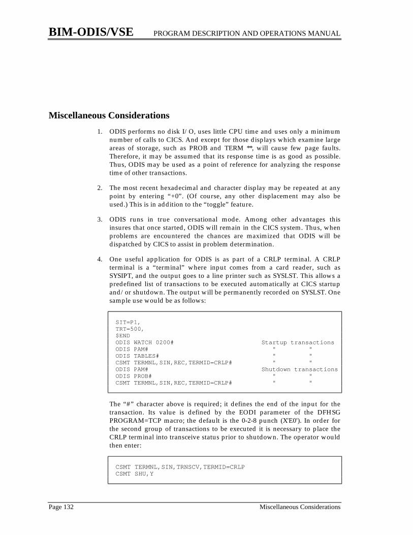
BIM-ODIS/VSE PROGRAM DESCRIPTION AND OPERATIONS MANUAL
Page 132 Miscellaneous Considerations
Miscellaneous Considerations1. ODIS performs no disk I/O, uses little CPU time and uses only a minimum
number of calls to CICS. And except for those displays which examine largeareas of storage, such as PROB and TERM **, will cause few page faults.Therefore, it may be assumed that its response time is as good as possible.Thus, ODIS may be used as a point of reference for analyzing the responsetime of other transactions.
2. The most recent hexadecimal and character display may be repeated at anypoint by entering “+0”. (Of course, any other displacement may also beused.) This is in addition to the “toggle” feature.
3. ODIS runs in true conversational mode. Among other advantages thisinsures that once started, ODIS will remain in the CICS system. Thus, whenproblems are encountered the chances are maximized that ODIS will bedispatched by CICS to assist in problem determination.
4. One useful application for ODIS is as part of a CRLP terminal. A CRLPterminal is a “terminal” where input comes from a card reader, such asSYSIPT, and the output goes to a line printer such as SYSLST. This allows apredefined list of transactions to be executed automatically at CICS startupand/or shutdown. The output will be permanently recorded on SYSLST. Onesample use would be as follows:
SIT=P1,TRT=500,$ENDODIS WATCH 0200# Startup transactionsODIS PAM# " "ODIS TABLES# " "CSMT TERMNL,SIN,REC,TERMID=CRLP# " "ODIS PAM# Shutdown transactionsODIS PROB# " "CSMT TERMNL,SIN,REC,TERMID=CRLP# " "
The “#” character above is required; it defines the end of the input for thetransaction. Its value is defined by the EODI parameter of the DFHSGPROGRAM=TCP macro; the default is the 0-2-8 punch (X'E0'). In order forthe second group of transactions to be executed it is necessary to place theCRLP terminal into transceive status prior to shutdown. The operator wouldthen enter:
CSMT TERMNL,SIN,TRNSCV,TERMID=CRLPCSMT SHU,Y
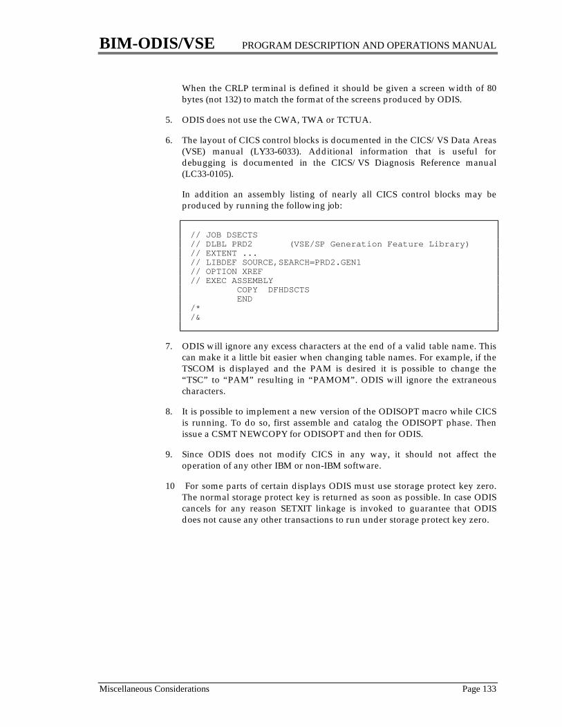
BIM-ODIS/VSE PROGRAM DESCRIPTION AND OPERATIONS MANUAL
Miscellaneous Considerations Page 133
When the CRLP terminal is defined it should be given a screen width of 80bytes (not 132) to match the format of the screens produced by ODIS.
5. ODIS does not use the CWA, TWA or TCTUA.
6. The layout of CICS control blocks is documented in the CICS/VS Data Areas(VSE) manual (LY33-6033). Additional information that is useful fordebugging is documented in the CICS/VS Diagnosis Reference manual(LC33-0105).
In addition an assembly listing of nearly all CICS control blocks may beproduced by running the following job:
// JOB DSECTS// DLBL PRD2 (VSE/SP Generation Feature Library)// EXTENT ...// LIBDEF SOURCE,SEARCH=PRD2.GEN1// OPTION XREF// EXEC ASSEMBLY COPY DFHDSCTS END/*/&
7. ODIS will ignore any excess characters at the end of a valid table name. Thiscan make it a little bit easier when changing table names. For example, if theTSCOM is displayed and the PAM is desired it is possible to change the“TSC” to “PAM” resulting in “PAMOM”. ODIS will ignore the extraneouscharacters.
8. It is possible to implement a new version of the ODISOPT macro while CICSis running. To do so, first assemble and catalog the ODISOPT phase. Thenissue a CSMT NEWCOPY for ODISOPT and then for ODIS.
9. Since ODIS does not modify CICS in any way, it should not affect theoperation of any other IBM or non-IBM software.
10 For some parts of certain displays ODIS must use storage protect key zero.The normal storage protect key is returned as soon as possible. In case ODIScancels for any reason SETXIT linkage is invoked to guarantee that ODISdoes not cause any other transactions to run under storage protect key zero.
BIM-ODIS/VSE PROGRAM DESCRIPTION AND OPERATIONS MANUAL
Page 134 Suspected Problems with ODIS
Suspected Problems with ODISODIS, like all other software products, can make no claim to infallability. Giventhe vast amount of data displayed by ODIS there is an equally vast number ofpossibilities for error. Although every attempt is made to see that this does notoccur it obviously must be anticipated. Before reporting a suspected problemplease review the following procedures:
1. Insure that the release level of ODIS matches the release levels of CICS andVSE.
2. ODIS displays exactly what it sees. Therefore, it must be determined if theproblem lies with the original data or with the manner in which ODISdisplays the data. To do this display the field with the normal formatteddisplay. Then display the same field in hexadecimal and character to see ifODIS has displayed the field correctly. The appropriate IBM documentationshould be consulted at this point.
3. Review the detailed descriptions in the section “Formatted ScreenDescriptions” starting on page 22. There may be special circumstances for thefield in question.
4. Certain fields may be accurately displayed by ODIS but give incorrect ormisleading information. If doubt exists that ODIS is displaying a valuecorrectly, in most cases the source of the information may be determined anddisplayed using the hexadecimal and character display function.
5. To insure the integrity of ODIS a number of internal checks are performed. Ifan unusual condition occurs ODIS will abend (producing a transactiondump). Contact your supplier of BIM-ODIS for assistance.
BIM-ODIS/VSE PROGRAM DESCRIPTION AND OPERATIONS MANUAL
Page 135
MESSAGES


BIM-ODIS/VSE PROGRAM DESCRIPTION AND OPERATIONS MANUAL
Messages Page 137
ODIS001 - 3270 terminals must have 80 column screen sizeODIS requires that 3270 terminals have either a default or alternate screen width of 80 bytes.The only IBM-defined 3270 terminal not supported by ODIS is the 3277 model 1 which has ascreen width of 40 bytes.
ODIS002 - ODISOPT disabled or not defined in PPT - default options usedThis message also appears on the operator's console. It indicates that the ODISOPT phasedoes not exist in the PPT or that it exists but is disabled. ODIS has used the default valuesdescribed in this manual.
ODIS003 - Invalid ODISOPT phase - default options usedThis message also appears on the operator's console. It indicates that some part of theODISOPT phase cannot be recognized by ODIS. Instead of using an invalid set of optionsODIS has used the default values described in this manual.
ODIS004 - Incorrect version of ODISOPT - default options usedThis message also appears on the operator's console. The ODISOPT phase contains a versionnumber. This mesage indicates that the version of ODIS being executed does not support theversion of the ODISOPT phase. The ODISOPT phase should be reassembled with a currentODISOPT macro. ODIS has used the default valued described in this manual.
ODIS005 - 3270 terminals must have 24, 32 or 43 row screen sizeODIS requires that 3270 terminals have either a default or alternate screen length of 24, 32 or43 rows. (The 27 row 3278-5 will always be used in its 24 row default mode.) The only 3270terminal not supported by ODIS is the 3277 model 1 which has a screen length of 12 rows.
ODIS006 - SCAN is permitted only on 3270 terminalsThe hexadecimal and character scan facility may only be utilized on 3270 terminals.
ODIS007 - Feature requires a security specificationThe text of this message has been intentionally been made somewhat vague in order to avoidgiving clues to potential security risks. It indicates that the ODISOPT phase has specified theSECTRAN parameter which requires users of certain features to initiate ODIS with aparticular transaction ID. The user receiving this message has used a different transaction IDand, thus, is prevented from using these features.
ODIS010 - Last entry in table has been processedAfter the last entry in a table has been displayed the operator requested the next entry byhitting the PF1 key.
ODIS011 - Invalid PA or PF keyThe operator has hit a PA key, PF key or other attention indicator (such as a magnetic stripereader) which is not currently allowed. With the default ODISOPT values the PF4, PF5, PF6,PF16, PF17, PF18, PA2, enter and clear keys are always valid. PF1, PF2, PF3, PF13, PF14and PF15 are often, but not always valid. The prompting line at the bottom of the screenshould be consulted for PF1, PF2 and PF3. The installation may have changed the PA and PFkey specifications in the ODISOPT macro. This message will also occur if a variable PF key(PF7-PF12 and PF19-PF24) is used at a terminal where it has not been previously given avalue.
BIM-ODIS/VSE PROGRAM DESCRIPTION AND OPERATIONS MANUAL
Page 138 Messages
ODIS012 - PF3 is permitted only for PCT TYPE=ENTRYThe transaction being displayed on the TRAN display is not defined as TYPE=ENTRY. ThePF3 key may not be used for such PCT entries.
ODIS013 - There is no data in Temp StorageThe operator has requested a TS display, but there is no data in Temporary Storage at thepresent time.
ODIS014 - All data ids are below XXXXXXXXThe operator has requested a Temporary Storage (TS) display beginning at xxxxxxxx. Thereis data in Temporary Storage, but all data IDs are below the specified value.
ODIS015 - There are no AIDs at this timeThe operator has requested an AID display, but there are no AIDs to be displayed.
ODIS016 - There are no ICEs at this timeThe operator has requested an ICE display, but there are no ICEs to be displayed.
ODIS017 - CICS was initiated without a DCTThe operator has requested a DEST display, but the Destination Control Table does not existbecause CICS was started with DCT=NO.
ODIS018 - No resources are currently enqueuedThe operator has requested an ENQ display, but there are no resources that are currentlyenqueued.
ODIS019 - Invalid table name specified - For a list of valid tables enter "MENU"The table name (first parameter) specified is invalid. To obtain a list of all of the formatteddisplays which are not security sensitive specify a table name of “MENU”.
ODIS020 - File not found in FCT: XXXXXXXXODIS021 - Program not found in PCT: xxxxxxxxODIS022 - Terminal not found in TCT: xxxxODIS023 - Trans id not found in PCT: XXXXODIS024 - Device address not found in PUB: XXXODIS025 - Channel queue contains only XXX entriesODIS026 - System contains only X'xx' task id'sODIS027 - Supervisor contains only XXX entries in Lock TableODIS028 - Destination not found in DCT: xxxx
The operator has requested a FILE, PROG, TERM, TRAN, PUB, CHANQ, TID, LOCK orDEST display. The entry specified does not exist.
ODIS030 - Address specified is not a valid virtual addressThe operator has specified an address for a hexadecimal and character display, but the addressdoes not currently exist. A valid address must be located in one of the following areas:1. The Supervisor2. A virtual partition in the same address space as CICS when the partition is running in
virtual mode3. A real partition in the same address space as CICS when the partition is running in real
mode4. The Shared Virtual Area (SVA)5. A partition in the Shared address space
BIM-ODIS/VSE PROGRAM DESCRIPTION AND OPERATIONS MANUAL
Messages Page 139
ODIS031 - Data was deleted from screen - Storage alteration has been suppressedThe operator has modified the lower portion of a hexadecimal character screen, presumablywhile using the storage alteration facility. But one or more characters were deleted using the3270 DEL, ERASE EOF or ERASE INPUT keys. To prevent unintended storage alterationODIS has performed no alterations and has redisplayed the data.
ODIS032 - Address on screen is no longer valid - storage alterationThe operator has requested storage alteration, but the data originally displayed is no longervalid. See message ODIS030 for more information.
ODIS033 - Address XXXXXX on screen was modified - Storage alteration terminatedWhile performing a storage alteration the operator has modified one of the addresses on theleft hand side of the screen. Since these addresses do not play an active role in storagealteration, ODIS assumes that the operator has done something incorrectly and stops anyfurther storage alteration.
ODIS034 - Invalid hex data at address XXXXXX - Storage alteration terminatedWhile performing a storage alteration the operator has entered data into the hexadecimalportion of the display which is not valid hexadecimal digits (0 through 9 or A through F).ODIS stops any further storage alteration.
ODIS035 - No scan data was enteredThe operator has requested a SCAN of storage, and ODIS has responded by providing ascreen for entering the scan type and data, but the operator did not enter any scan data.
ODIS036 - Scan data contains non-hexadecimal digit(s)While entering SCAN parameters the operator has specified a hexadecimal (H) scan, but thedata contains one or more characters which are not valid hexadecimal digits (0 through 9 or Athrough F).
ODIS037 - Hexadecimal scan data must contain an even number of digitsWhile entering SCAN parameters the operator has specified a hexadecimal (H) scan, but thedata contains an odd number of otherwise valid digits. Since the scan data must represent anumber of full bytes there must be an even number of digits.
ODIS038 - Scan format must be C (char) or H (hexadecimal)While entering SCAN parameters the operator has either failed to enter the scan format orentered a value other than C or H.
ODIS039 - Scan case must be U (upper), M (mixed) or I (ignore)While entering SCAN parameters the operator has entered an invalid case specification.
ODIS040 - Invalid time intervalThe operator has requested time-initiated mode or Watchdog mode but has specified a timeinterval that is zero, non-numeric or less than the value specified by the TIMEMIN parameterof the ODISOPT macro.
ODIS044 - Invalid partition id: XXThe operator has entered a partition ID which is not valid (BG or Fn) or does not exist for theSupervisor being used (e.g. F9 in an 8 partition system).
ODIS045 - Invalid decimal number: XXXThe operator has entered the specified data, but it contains nondecimal digits.
BIM-ODIS/VSE PROGRAM DESCRIPTION AND OPERATIONS MANUAL
Page 140 Messages
ODIS046 - Toggle is not valid until there have been two different displaysThe operator has attempted to use the toggle (PA2) feature before two different screens havebeen displayed.
ODIS048 - Unable to locate console buffer in SupervisorThis is probably caused by a conflict in release levels of CICS and VSE or by unusualSupervisor generation parameters.
ODIS049 - POWER command was omittedAn operator on a non-3270 terminal has requested a POWER function but has neglected tosupply the POWER command.
ODIS050 - Unable to define SPMXECB after 30 seconds - Hit enter to continueODIS uses the standard CTLSPOOL interface to POWER. This facility is currently being usedby another user. This may be another CICS transaction, ICCF or a batch partition.
ODIS051 - CTLSPOOL error X'xx'POWER has rejected the command submitted by ODIS. See the appropriate POWERdocumentation for an explanation of the return code.
ODIS052 - Unable to delete SPMXECB - RC=X'xx'This is probably caused by an error in ODIS or by some unusual occurrence in the CICSpartition.
ODIS053 - SYSxxx is not defined in the CICS partitionThe operator has requested a SEG function but has specified a SYS number greater than themaximum defined in the Supervisor for the CICS partition.
ODIS054 - SYSxxx is not assigned to a printerThe operator has requested a SEG function but the SYS number specified is not ASSGNed toa printer.
ODIS056 - XXXXXX does not exist for this terminalThe operator has requested one of the special hexadecimal and character displays for aparticular terminal; however, the desired control block does not currently exist for thespecified terminal. For example, the EIB does not exist for macro level programs, the NIBdoes not exist for BTAM terminals, and the TCA does not exist if a task is not running at theterminal.
ODIS057 - XXXXXX does not exist in this systemThe operator has symbolically requested a hexadecimal and character display, but the controlblock does not currently exist. For example, the JCT exists only if Journalling is generated.
ODIS058 - VTAM is not activeThe operator has requested a VBUF display, but VTAM is not currently active.
ODIS059 - DL/I is not active in the CICS partitionThe operator has requested a DLI display, but DL/I is not supported in the CICS partition, i.e.DLI=NO in the SIT. Operation of DL/I in batch partitions does not affect this message.
ODIS060 - VM is not activeThe operator has attempted to issue a CP command, but VSE is not running under the controlof VM.

BIM-ODIS/VSE PROGRAM DESCRIPTION AND OPERATIONS MANUAL
Messages Page 141
ODIS062 - CP command was omittedAn operator on a non-3270 terminal has requested a CP function but has neglected to supplythe CP command(s).
ODIS063 - WATCHDOG is not activeThe operator has attempted to turn The Watchdog facility off, but it is not currently active.
ODIS064 - Previous WATCHDOG has been turned offThe operator has requested that The Watchdog facility be turned on, but a previous Watchdogwas active. It has been turned off. The new command will take place as if this situation hadnot occurred.
ODIS065 - Invalid terminal id for The Watchdog: xxxxThe operator has requested that The Watchdog facility be turned on, but the terminal IDspecified by the WATTERM parameter of the ODISOPT macro does not exist in the CICSsystem. After reassembling ODISOPT it will be necessary to issue a CSMT NEWCOPY onboth ODISOPT and ODIS.
ODIS066-xx - hh:mm:ss problem descriptionThis message is produced by The Watchdog facility at the terminal specified by theWATTERM parameter of the ODISOPT macro. It describes a potential problem that mayneed corrective action. xx is a two digit number that uniquely describes the potential problemas discussed in the description of the PROB display. This number may be used in theWATSUPR parameter of the ODISOPT macro or with the DISABL function to suppresscertain messages.
ODIS067 - Terminal is neither local BTAM 3277 nor defined in ODISOPTThe operator has requested that a VM RESET command be issued for the terminal, but theterminal is not a local BTAM 3277 terminal. Furthermore, the ODISOPT macro has not beengenerated to include this terminal. All other terminals, such as local VTAM terminals, may beRESET by specifying ODISOPT macros with the TERMID and CUU parameters.
ODIS068 - Unsupported VTAM release (XXXX)The release levels of ODIS and ACF/VTAM do not match. The field (xxxx) is taken from thefirst four bytes of the ATCVT and indicates the release level of VTAM. Please order amatching release of ODIS.
ODIS069 - Security key at terminal XXXX will not allow YYYY to runThe operator has issued a WATCH request to turn The Watchdog on which will usetransaction ID yyyy, which is secured (DFHPCT TYPE=ENTRY,TRANSEC=n). However,the security key of the terminal ID, xxxx, specified in the WATTERM parameter of theODISOPT macro is such that it will not allow transaction yyyy to be initiated. One of thefollowing actions must be performed before a retry of the WATCH request can be performedat terminal xxxx:1. Assemble a new TCT specifying the required OPERSEC parameter for the terminal2. Sign on to the terminal with the CSSN transaction3. Remove or alter the transaction security key of yyyy to match the security key of the
terminal4. Use the storage alteration facility of ODIS to change the security key of the terminal
BIM-ODIS/VSE PROGRAM DESCRIPTION AND OPERATIONS MANUAL
Page 142 Messages
ODIS070 - Screen image has been lost - reenterThe operator has cleared the data on a 3270 screen without hitting the clear key. This can becaused by turning the power to the terminal off and on or by switching the test/normal switch.In VM environments this can be caused by DETACHing and ATTACHing the virtualterminal. In VTAM environments this can be caused by hitting the SYS REQ key while ODISis active at a terminal. This message will usually occur as the terminal operator attempts toenter what is believed to be a new transaction (which is not necessarily an ODIS transaction).
ODIS072 - Invalid PF key - only PF7-PF12 and PF19-PF24 are allowedThe operator has requested that the current table and entry name be assigned to a PF key buthas specified something besides PF7-PF12 or PF19-PF24.
ODIS073 - Error in VSAM control blocks: X XXXXXX XXXXXX XXXXXXWhile examining VSAM control blocks for a FILE display ODIS has detected an apparenterror. All unaffected fields are displayed normally.
ODIS074 - No file uses VSAM shared resourcesThe operator has requested an SR display, but this is not possible because none of the files inthe FCT uses VSAM Shared Resources (which is defined by DFHFCTTYPE=DATASET,SERVREQ=(SHARE,...)
ODIS075 - WRITEQ TD error X'xx' for function yyyyy destination zzzzWhile writing to Transient Data ODIS received return code X'xx'. yyyyyy will be CP,POWER, STGALT, VTAM or WATCH to indicate which function is being performed. zzzzis the Transient Data destination from the LOGCP, LOGPOW, LOGSA, LOGVTAM orLOGWAT parameter of the ODISOPT macro.
ODIS076 - Watchdog exit routine #1 disabled or not defined in PPTThe Watchdog has attempted to link to the user exit program defined by the WATXIT1parameter in the ODISOPT macro, but this program does not exist in the PPT or it exists butis disabled. ODIS will not attempt to invoke this user exit again until a CEMT NEWCOPY isissued for ODIS. This message appears on the operator's console.
ODIS077 - Watchdog exit routine #2 disabled or not defined in PPTSame as ODIS076, for WATXIT2.
ODIS078 - Unable to locate SDAIDS save areaODIS cannot locate the SDAIDS SAVE AREA table in the Supervisor and is, thereforeunable to produce the LOCK or TID display. This may be due to a nonstandard Supervisormodification or to a software product modifying the field in the SYSCOM (IJBSAVSD)which points to the SDAIDS save area.
ODIS079 - Invalid hexadecimal number: XXThe operator has entered the specified data, but it contains nonhexadecimal digits.
ODIS080 - Invalid cursor position - cursor ignoredThe operator has attempted to select a hex+character display based on cursor positioning buthas placed the cursor at an invalid location. The cursor has been ignored, and the original datahas been redisplayed.
ODIS081 - hh:mm:ss termid operid messagetextThis message appears on the VSE console if LOGCP=YES, LOGPOW=YES, LOGSA=YESor LOGVTAM=YES was specified in the ODISOPT macro. The time, terminal ID and
BIM-ODIS/VSE PROGRAM DESCRIPTION AND OPERATIONS MANUAL
Messages Page 143
operator ID are added to the text of the CP command, POWER command, storage alterationrequest or VTAM command.
ODIS082 - Invalid problem number: XXThe operator has attempted to ENABLE or DISABL a Watchdog message, but the problemnumber is either non-numeric or outside the range 1-64.
ODIS083 - Time-initiated mode has been terminatedThe terminal had been running in time-initiated mode, and the terminal is now returning tonormal operation. This may be due to the operator hitting a PA or PF key or by the TIMEITparameter of the ODISOPT macro being exceeded.
ODIS084 - Unable to locate lock table - Reason=nODIS cannot locate the lock table in the Supervisor and is, therefore, unable to display thelocks in the LOCK display.
ODIS085 - Mismatch in time-initiated dataThis is almost certainly caused during the installation of a new release of ODIS and is causedby issuing a CSMT NEWCOPY for ODIS while a transaction is running in time-initiated orWatchdog mode.
ODIS086 - VTAM command was omittedAn operator on a non-3270 terminal has requested a VTAM function but has neglected tosupply the VTAM command.
ODIS087 - This CICS system does not support VTAMThe operator has requested a VTAM function, but it cannot be executed because the CICSsystem does not use VTAM.
ODIS088 - The CICS VTAM ACB is closedThe operator has requested a VTAM function, but it cannot be executed because CICS's ACBis currently closed.
ODIS089 - CICS was not defined to VTAM with AUTH=SPOThe operator has requested a VTAM function, but it cannot be executed because the APPLstatement defining CICS to VTAM does not include AUTH=SPO.
ODIS090 - GENCB error X'nn'ODIS has issued a GENCB macro and has received the specified return code. This is probablycaused by running ODIS under an unsupported release of VSE or VTAM.
ODIS091 - SENDCMD error X'nn'ODIS has issued a SENDCMD macro and has received the specified return code. This isprobably caused by an error in ODIS.
ODIS092 - RCVCMD error X'nnnn'ODIS has issued a RCVCMD macro and has received the specified return code. This isprobably caused by an error in ODIS.
ODIS096 - Program is not currently in storageThe operator has requested that the start of a program be displayed by using the PF3 key onthe PROG display, but the program is not currently in storage. Therefore, it cannot bedisplayed.
BIM-ODIS/VSE PROGRAM DESCRIPTION AND OPERATIONS MANUAL
Page 144 Messages
ODIS097 - Attempt to start ODIS by an invalid methodThe operator has attempted to start ODIS by a method not described in this manual, forexample executing an EXEC CICS START with the CECI transaction.
ODIS100 - Abend xxxx has been detected in The Watchdog - RecoveredAbend XXXX has been detected during execution of the Watchdog. In order to prevent thisfrom terminating The Watchdog, the actual abend has been intercepted and will not occur,although a transaction dump with the abend code of WDOG will be taken. If XXXX is AICA,this represents a runaway task and is probably the result of some environmental factor, such ashitting STOP on the CPU, and is probably not due to a programming error in The Watchdog.If XXXX is any other value, it probably represents a programming error in The Watchdog orin a Watchdog user exit. This message appears on the operator's console. Although somepotential problems may go unreported this time, The Watchdog will continue to run.
ODIS101 - No TCTSEs in systemThe operator has requested a SYSTEM display, but the CICS system contains no TCTSEs.This should not occur.
ODIS102 - PF1 is not allowed for this surrogate TCTTEThe operator has displayed a surrogate TCTTE (one representing a terminal attached toanother CICS system) which does not have a corresponding surrogate TCTTE. The PF1 keyfunction is not available for this terminal.
ODIS103 - Time-initiated mode is not allowed when using CRTEThe operator has requested that time-initiated be started; however, due to the technique usedby CRTE, this cannot be performed.
ODIS104 - Error N in low storageAn integrity check has shown that a pointer in the low storage area of the Supervisor is not setas expected. The requested action cannot be performed.
ODIS105 - Cross-space display is not permittedThe operator has entered a table name which is a valid partition ID, but the partition's storagecannot be displayed because it resides in a different space than CICS.
ODIS106 - Only NNNNN entries currently existThe operator has requested that a number of entries be skipped on an AID, ENQ or ICEdisplay, but there are fewer entries in existence than the number specified.
ODIS107 - Invalid trans id for Watchdog: XXXXThe operator has requested that The Watchdog facility be turned on, but the transaction IDspecified by the WATTRAN parameter of the ODISOPT macro does not exist in the CICSsystem. After reassembling ODISOPT it will be necessary to issue a CEMT or CSMTNEWCOPY for both ODIS and ODISOPT.
ODIS108 - Invalid TRAK function: XXXThe operator has requested a TRAK function, but the entry name is not one of the valid ones.
ODIS109 - ODISTRAK is already onThe operator has requested that ODISTRAK be turned on, but ODISTRAK is already on.

BIM-ODIS/VSE PROGRAM DESCRIPTION AND OPERATIONS MANUAL
Messages Page 145
ODIS110 - ODISTRAK is not currently onThe operator has requested that ODISTRAK be turned off, but ODISTRAK does not need tobe turned off because it is not currently on.
ODIS111 - ODISTRAK is now activeThe ODISTRAK feature has been turned on by either PLTPI processing or by entering TRAKON. This message is written to the operator console.
ODIS112 - ODISTRK not in FCT or not usableThe ODISTRAK feature cannot be turned on because the FCT does not contain an entry forODISTRK or the file is disabled or closed.
ODIS113 - messageAn unusual error has occurred during ODISTRAK processing. This message is written to theoperator console.
ODIS114 - ODISTRK WRITE error X'xxxxxxxx' RC=yy EC=zzThe ODISTRAK feature has encountered the indicated error while trying to write to theODISTRK file. 'yy' and 'zz' are the VSAM return code and error code; under somecircumstances these will not appear.
ODIS115 - ODISTRK file is fullThe ODISTRK file has become full including the primary and secondary allocations, if any.The file should archived to preserve the data already written and/or reDEFINEd.
ODIS116 - ODISTRK file has been closed - ODISTRAK continuesThe ODISTRK file has been closed (probably by using CEMT) during normal processing.Unless ODISTRK is explicitly turned off, writing will automatically resume when the file isopened.
ODIS118 - Final ODISTRK records have been writtenThis message is written to the console after the final set of ODISTRAK records have beenwritten during CICS shutdown, or when TRAK OFF is issued.
ODIS120 - Shared Resource pool #X does not existThe operator has requested the display of a shared resource pool which is not used by any ofthe currently defined files.
ODIS121 - CICS was started with FCT=NOThe operator has requested an SR display, which is meaningless in a CICS system with nofiles.
ODIS123 - ODISTRAK has been turned on STATUS: XXXXXXXXXXODISTRAK has been successfully initiated. It will write data periodically to the ODISTRKfile unless the status of the file is such that it is not possible to do so. The status value may be:RECORDING DATA The first set of records has been written successfully.UNKNOWN At this point in time it is not known if records have been written
successfully.OTHER An error message which also appears on the console.If an error has occurred which prevents writing of records at this time, ODISTRAK willcontinue to attempt to write its records at the expiration of its time interval.
BIM-ODIS/VSE PROGRAM DESCRIPTION AND OPERATIONS MANUAL
Page 146 Messages
ODIS124 - Final ODISTRAK records could not be writtenODISTRAK has been turned off successfully. However, the status of the ODISTRK file issuch that the final set of records could not be written. For example, the file may be disabled.
ODIS125 - Unexpected return code XXXXXXXXXXXX to YYYYYYYYYYYYODIS has issued a CICS command and has received an unexpected response. This should notoccur.
ODIS126 - Watchdog initiation error XXXXXXXXXXXX - Unable to continue The WatchdogThe Watchdog has been running successfully for a period of time, but an error has occurredwhich prevents subsequent invocations.
ODIS127 - ODISTRAK Temp Storage contains XXX items - Attemping to continueAn internal error has been detected in ODISTRAK's usage of Temporary Storage.
(ODIS7nn messages are produced by ODISTRAK batch program)
ODIS701 - INVALID KEYWORD: xxxxxxxxThe first “word” on the card is not one of the valid keywords such as Range, Report, ect.
ODIS703 - INVALID PARAMETER NAME: xxxxxxxxThe specified parameter name is not valid for the keyword with which it appears.
ODIS704 - INVALID TYPE OF xxxxxxxx PARAMETERThe specified parameter name, while valid, is used improperly. For example, it is not followedby an equal sign.
ODIS705 - INVALID xxxxxxxx VALUE: yyyyyyyyThe value assigned to the xxxxxxxx parameter is invalid. For example, MAYBE is not a validvalue for the CLEAR parameter of the ARCHIVE statement.
ODIS707 - xxxxxxxx yyyyyyyy APPEARS MORE THAN ONCEThe yyyyyyyy parameter on the xxxxxxxx statement has been specified more than once.
ODIS708 - INVALID xxxxxxxx PARAMETER value: yyyyyyyyThe xxxxxxxx statement contains an invalid parameter
ODIS709 - INVALID RANGE START�END DATE�TIMEThe specified parameter contains nonumeric characters or is not in the proper format.
ODIS710 - SYNTAX ERROR IN xxxxxxxx PARAMETER NEAR COLUMN yyThe rules for coding parameter values have been violated. For example, two commas appearin succession..
ODIS721 - INPUT FILE IS EMPTYA REPORT has been attempted, but the input file (either ODISTRAK or an archive tape)contains no records.
ODIS722 - THE SPECIFIED RANGE DOES NOT ENCOMPASS AT LEAST TWO INTERVALSIn order to report activity within a given range, at least two intervals (or a startup followed byone interval) must exist, but either zero or one interval has been observed. Rerun the reportwith a wider range.
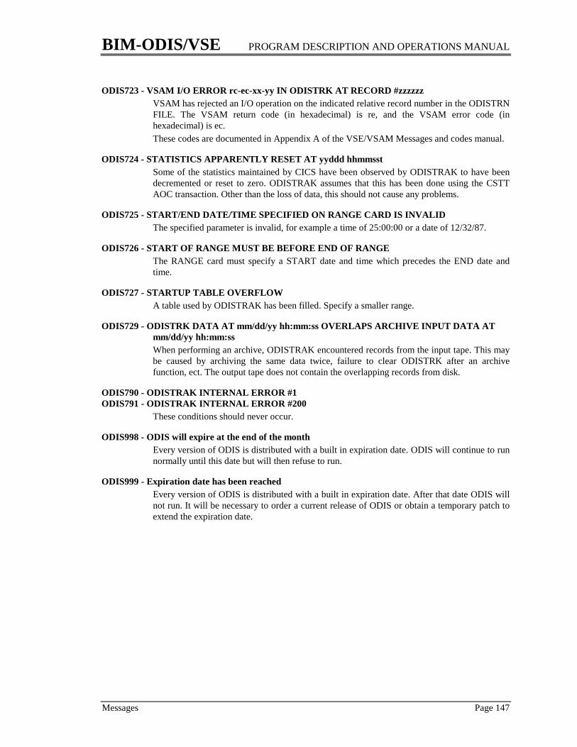
BIM-ODIS/VSE PROGRAM DESCRIPTION AND OPERATIONS MANUAL
Messages Page 147
ODIS723 - VSAM I/O ERROR rc-ec-xx-yy IN ODISTRK AT RECORD #zzzzzzVSAM has rejected an I/O operation on the indicated relative record number in the ODISTRNFILE. The VSAM return code (in hexadecimal) is re, and the VSAM error code (inhexadecimal) is ec.These codes are documented in Appendix A of the VSE/VSAM Messages and codes manual.
ODIS724 - STATISTICS APPARENTLY RESET AT yyddd hhmmsstSome of the statistics maintained by CICS have been observed by ODISTRAK to have beendecremented or reset to zero. ODISTRAK assumes that this has been done using the CSTTAOC transaction. Other than the loss of data, this should not cause any problems.
ODIS725 - START/END DATE/TIME SPECIFIED ON RANGE CARD IS INVALIDThe specified parameter is invalid, for example a time of 25:00:00 or a date of 12/32/87.
ODIS726 - START OF RANGE MUST BE BEFORE END OF RANGEThe RANGE card must specify a START date and time which precedes the END date andtime.
ODIS727 - STARTUP TABLE OVERFLOWA table used by ODISTRAK has been filled. Specify a smaller range.
ODIS729 - ODISTRK DATA AT mm/dd/yy hh:mm:ss OVERLAPS ARCHIVE INPUT DATA ATmm/dd/yy hh:mm:ssWhen performing an archive, ODISTRAK encountered records from the input tape. This maybe caused by archiving the same data twice, failure to clear ODISTRK after an archivefunction, ect. The output tape does not contain the overlapping records from disk.
ODIS790 - ODISTRAK INTERNAL ERROR #1ODIS791 - ODISTRAK INTERNAL ERROR #200
These conditions should never occur.
ODIS998 - ODIS will expire at the end of the monthEvery version of ODIS is distributed with a built in expiration date. ODIS will continue to runnormally until this date but will then refuse to run.
ODIS999 - Expiration date has been reachedEvery version of ODIS is distributed with a built in expiration date. After that date ODIS willnot run. It will be necessary to order a current release of ODIS or obtain a temporary patch toextend the expiration date.

Index
BIM-ODIS Page 149
A
AID ............................................................23, 38AMXT............................................................124
CSA Screen ..............................................28ARCHIVE .....................................................100ASSGN ............................................................42ATCVT ............................................................20AUTH=SPO......................................................7AVT .................................................................20
B
BFPL ................................................................32BFRUSE...........................................................20BTAM
LINE Screen.............................................39Buffers ...........................................................124
C
CHANQ ....................................................24, 58COMREG........................................................25COMRG ..........................................................20CONSOL.........................................................26Control
Area ........................................................127PROB #25...............................................54
Interval...........................................123, 125PROB #26...............................................54
Interval Splits ........................................126CP ..............................................................27, 59
SECTRAN................................................10CRLP .............................................................132Cross Address Space Access ........................93CSA..................................................................28Current Address Space .................................93Cursor Positioning.........................................94Cushion...........................See Storage CushionCVT..................................................................20CWA........................................................20, 133
D
DCA...........................................................71, 75DCT ...........................................................20, 31Debugging ....................................................122DEMO .............................................................30DEST................................................................31DIB...................................................................20Dispatch Control Area ..................................71DLI.............................................................20, 32
FILE Screen..............................................34PROB #13.................................................52
PROB #14.................................................52DLIAL .............................................................20DSA................................................................115
Alternate Names.....................................20Page Allocation Map..............................45PROB #18.................................................53PROB #2...................................................51PROB #23.................................................54PROB #29.................................................54Res vs Non-Res Programs ...................118Special Entry Names ..............................75Storage Alteration...................................95Storage Violation ..................................120Temporary Storage...............................120TERM Screen...........................................74Transaction Storage..............................119
DSECTS.........................................................133Dynamic Storage Area .............. 115. See DSA
E
EIB....................................................................75EIS ....................................................................75Enhancements ..................................................4ENQ.................................................................33Enqueue ..........................................................33Exclusive Control.........................................123
F
FCT ..................................................................20FILE Screen..............................................34FILE* Screen ............................................36
FILE .................................................................34FILE*................................................................36FILE** ..............................................................37Formatted Screen Descriptions ....................22Freeze ......................................................82, 122
G
GETVIS..................................20, 25, 63, 67, 117GETVIS Usage..............................................126
H
HELP ...............................................................20HLL..................................................................75
I
ICCF...........................................20, 79, 115, 117ICE .............................................................23, 38Installation ........................................................5
Index
Page 150 BIM-ODIS
J
JA............................................................... 20, 47JCT .................................................................. 20Job Accounting........................................ 20, 47
L
LECB............................................................... 75LINE ............................................................... 39LOCK.............................................................. 40Logging
ODIS Command....................................... 8Logical Unit ................................................... 42LTA ................................................. 9, 20, 68, 79lub ................................................................... 49LUB................................................................. 42
M
MAP................................................................ 20Maximum
Active TasksCSA Screen ............................................ 28
TasksCSA Screen ............................................ 28PROB #6 ................................................ 52PROB #63 .............................................. 55
MCT................................................................ 20MENU ............................................................ 43Message Suppression ................................. 107Messages ...................................................... 137MRO ....................................................... 76, 105Multiple Address Space Access .................. 93Multi-Region Operation....................... 76, 105MXT
CSA Screen ............................................. 28
N
NamesAlternate ................................................. 20Special ..................................................... 75
NEWCOPY .................................... 57, 117, 133CICS Table Entries................................... 6PROB #29................................................ 54
NIB.................................................................. 75
O
ODISEXIT................................................. 5, 109ODISOPT ........................... 5, 7, 13, 18, 51, 133ODISTRAK .................................................... 97
File Definition......................................... 97PLTPI....................................................... 10Report Formats..................................... 101
Resetting Statistics ............................... 104SECTRAN ............................................... 10Start and Stop ......................................... 81TRKINT................................................... 12TRKTRAN............................................... 12
OPFL............................................................... 20
P
Page Allocation Map .................................... 45Paging............................................................. 68PAM................................................ 45, 116, 118
Transaction Storage ............................. 119PART............................................................... 47Partition
control block ........................................... 79Information Block .................................. 49Status ................................................. 47, 49
PC.................................................................... 20PCB ................................................................. 79PCBA .............................................................. 20pct.................................................................... 82PCT ................................................................. 20PF Keys
Bottom Screen Line................................ 22Ease of Use............................................ 129Fixed PF Keys ......................................... 17Optional Entries ....................................... 6PA2 ............................................................ 9PF Screen................................................. 48PFn ............................................................. 9PFnTAB ................................................... 10Storage Display ...................................... 93Transaction Initiation ............................ 19Variable PF Keys.................................... 18
Physical I/Os ............................................... 125Physical Unit Block ....................................... 58PIB................................................................... 49PLTPI .......................................................... 7, 12
Watchdog Mode................................... 107PLTSD............................................................... 7PMCOM ......................................................... 20POWER..................................................... 50, 62
SECTRAN ............................................... 10PPT............................................................ 20, 57PROB............................................................... 51Problem Numbers......................................... 51
Message Suppression .......................... 107WATSUPR .............................................. 12
Problems......................................................... 51Message Suppression .......................... 107Problem Determination....................... 110

Index
BIM-ODIS Page 151
Suspected with ODIS ...........................134Watchdog Mode ...................................106
PROG.......................................................57, 118Program Check/Abend Trace Table...70, 122Program Control Table .................................82PROGST ..........................................................57PSS ...................................................................20PST...................................................................75PTA..................................................................20PUB..........................................................58, 127PUBOWN .................................................20, 58
R
R14 ...................................................................75RAS..................................................................20Release Dependencies...................................13RESET..............................................................59RPL ..................................................................75Runaway Tasks
PROB #10.................................................52PROB #5...................................................52
S
Scan Storage ...................................................60SCBA ...............................................................20SCD..................................................................32SDAID .............................................................20SDL ............................................................20, 67SECHEX..........................................................10SECTRAN.......................................................10
CICS Table Entries....................................6CP Screen.................................................27SEG Screen ..............................................62Storage Alteration ..................................94Storage Display.......................................93VTAM Screen..........................................88WATCH Screen ......................................90Watchdog Mode ...................................107WATTRAN..............................................12
Security .....................................................27, 62CICS Table Entries....................................6SECTRAN................................................10Storage Alteration ..................................94Storage Display.......................................93VTAM Screen..........................................88WATCH Screen ......................................90Watchdog Mode ...................................107
SEG ..................................................................62SECTRAN................................................10
Segment...........................................................62SECTRAN................................................10
Shared Resources...........................65, 125, 126Shared Virtual Area.......................................67Short On Storage................................. See SOSSIT....................................................................20SMCB...............................................................63SMCOM ..........................................................20SOS
AID Screen...............................................23CICS Table Entries....................................6CSA Screen ..............................................28Dynamic Storage Area .........................115PROB # 1..................................................51PROB #28.................................................54PROB #29.................................................54PROB #62.................................................55Transaction Storage..............................119Watchdog Mode ...................................107
SPACE.............................................................64SR .....................................................65, 125, 126SRT...................................................................20SSA...................................................................20Stall Purge.............................................115, 116STCA .......................................................75, 122Storage
Alteration.........................................94, 122SECTRAN ..............................................10
Cushion..................................115, 117, 118CSA Screen.............................................28PROB #29...............................................54
Display .....................................................92SECTRAN ..............................................10
Freeze ...............................................82, 122Scan...........................................................60Utilization ..............................................115Violation...............................45, 66, 82, 120
PROB #4.................................................51PROB #60...............................................55
Strings....................................124, 125, 126, 127Suffix ...............................................................70SV.....................................................................66SVA..................................................................67Symbolic Unformatted Displays..................20SYSCOM .................................................68, 127SYSTEM ..........................................................69System Communication Region...................68
T
TABLES...........................................................70Task
Control Block...........................................79Displays .............................................71, 73

Index
Page 152 BIM-ODIS
Information Block .................................. 79TASKREQ ........................................................ 6TCA................................................................. 75TCB ................................................................. 79TCT ............................................... 20, 74, 77, 78TCTFX ............................................................ 20TCTLE ............................................................ 75TCTSE............................................................. 75TCTUA ......................................................... 133Temporary Storage ......................... 84, 86, 120
PROB #11................................................ 52PROB #24................................................ 54
Terminal Status Displays ................. 74, 77, 78Terminal Support.......................................... 13Threshold Values .......................................... 11THSTOR
PROB #18................................................ 53TIB................................................................... 79TIBA................................................................ 20TID .................................................................. 79Time-Initiated Mode................................... 105TIOA ............................................................... 75Toggle ............................... 10, 18, 112, 129, 132
PA2 ............................................................ 9TRAK.................................81. See ODISTRAKTRAN.............................................................. 82Transient Data ............................................... 31TS .................................................................... 84TSBM .............................................................. 20TSCOM................................................... 86, 120TST.................................................................. 20TSUT............................................................... 20Tuning VSAM ............................................. 123TWA ....................................................... 75, 133
U
UNDIAL......................................................... 20UTCA.............................................................. 75
V
VBUF .............................................................. 87VM ...................................................... 13, 20, 59
SECTRAN ............................................... 10VM commands .............................................. 27VSAM
Appl Prog Considerations .................. 127Buffers ................................................... 124FILE Screen............................................. 34FILE* Screen ........................................... 36LOCK Screen .......................................... 40Physical I/Os........................................ 125
Special Entry Names ............................. 75SR Screen................................................. 65Strings.................................................... 124Tuning ................................................... 123
VTAM............................................................. 88Installation ................................................ 7LINE Screen............................................ 39PROB #27 ................................................ 54SECTRAN ............................................... 10VBUF Screen........................................... 87
W
Watchdog ..................................................... 106LOGxxxx ................................................... 8Message Suppression .......................... 107PLTPI ......................................................... 7PROB #60-63........................................... 55PROB Screen........................................... 51SECTRAN ............................................... 10Start and Stop ......................................... 90Storage Utilization ............................... 116THxxxxx .................................................. 11Transaction Storage ............................. 120User Exits .............................................. 108WATINT ................................................. 12WATSUPR .............................................. 12WATTERM ............................................. 12WATTRAN ............................................. 12WATXIT1 ................................................ 12WATXIT2 ................................................ 12
WATINT......................................................... 12WATCH Screen...................................... 90
WATSUPR ..................................................... 12WATTERM .................................................... 12
PROB #60 ................................................ 55WATTRAN .................................................... 12WATXIT1 ............................................... 12, 108WATXIT2 ............................................... 12, 108WECB ............................................................. 75WHO............................................................... 91WS ................................................................... 75