bimification -...
TRANSCRIPT

Faculty of Civil Engineering, Institute of Construction Informatics, Prof. Dr.-Ing. Raimar J. Scherer
BIMificationeine neue Herausforderung an die Bauinformatik
FBI, Dresden 6.9.2017
Prof. Raimar Scherer
2TU Dresden, Institute of Construction Informatics, Prof. Dr.-Ing. Raimar J. Scherer
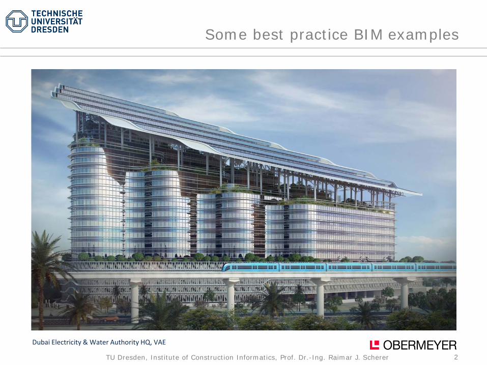
Some best practice BIM examples
Dubai Electricity & Water Authority HQ, VAE
3TU Dresden, Institute of Construction Informatics, Prof. Dr.-Ing. Raimar J. Scherer
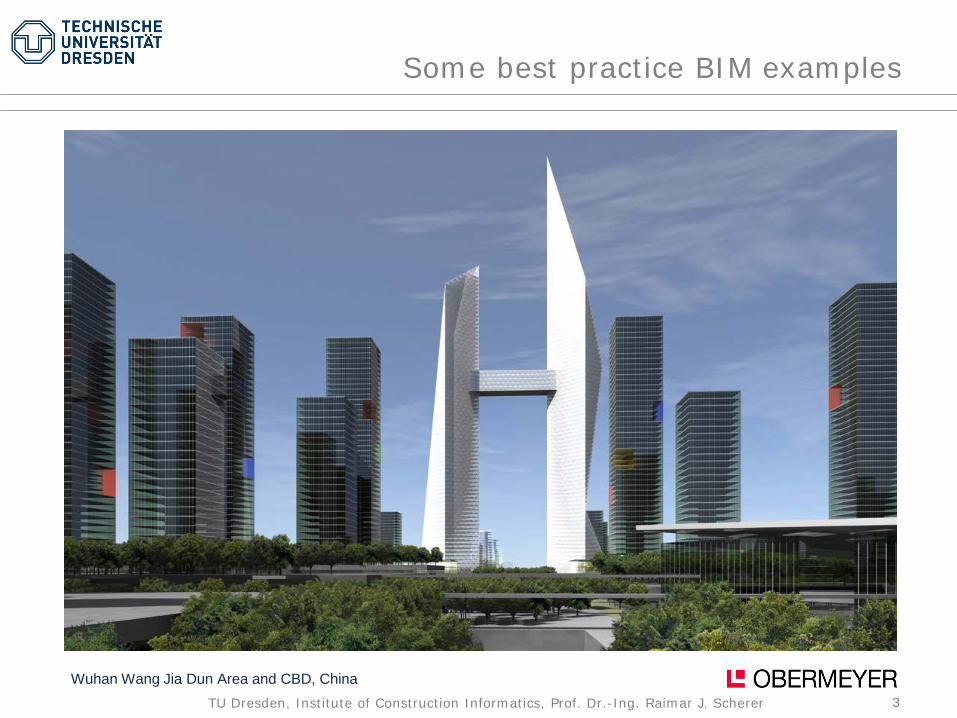
Some best practice BIM examples
Wuhan Wang Jia Dun Area and CBD, China
4TU Dresden, Institute of Construction Informatics, Prof. Dr.-Ing. Raimar J. Scherer
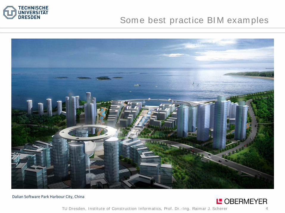
Some best practice BIM examples
Dalian Software Park Harbour City, China
5TU Dresden, Institute of Construction Informatics, Prof. Dr.-Ing. Raimar J. Scherer
Was ist BIM ?

6TU Dresden, Institute of Construction Informatics, Prof. Dr.-Ing. Raimar J. Scherer
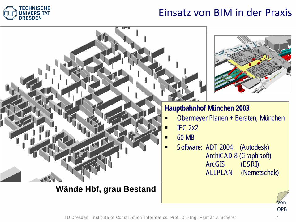
BIM Einsatz in der PraxisEinbindung des Transrapid in den HBF München
Hauptbahnhof München 2003 Obermeyer Planen + Beraten, München IFC 2x2 60 MB Software: ADT 2004 (Autodesk)
ArchiCAD 8 (Graphisoft)ArcGIS (ESRI)ALLPLAN (Nemetschek)
STAND 2003
Von OPB
7TU Dresden, Institute of Construction Informatics, Prof. Dr.-Ing. Raimar J. Scherer
Wände Hbf, grau Bestand
Bsp: Ausschreibung Hbf München / 2003 Komplexes (Um-) Bauvorhaben
und Infrastrukturmaßnahmen Vollständiges Modell in IFC 2x2
(Obermeyer Planen + Beraten) Modellvolumen: ca. 60 MB Software: ADT 2004 (Autodesk)
ArchiCAD 8 (Graphisoft)ArcGIS (ESRI)
Hauptbahnhof München 2003 Obermeyer Planen + Beraten, München IFC 2x2 60 MB Software: ADT 2004 (Autodesk)
ArchiCAD 8 (Graphisoft)ArcGIS (ESRI)ALLPLAN (Nemetschek)
Einsatz von BIM in der Praxis
Von OPB
8TU Dresden, Institute of Construction Informatics, Prof. Dr.-Ing. Raimar J. Scherer
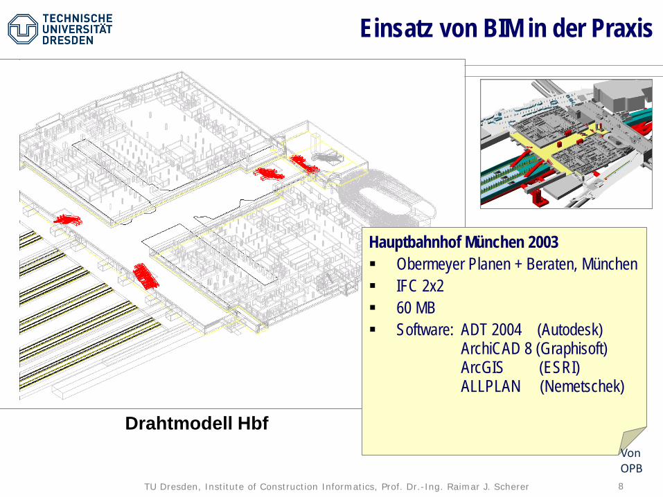
Drahtmodell Hbf
Hauptbahnhof München 2003 Obermeyer Planen + Beraten, München IFC 2x2 60 MB Software: ADT 2004 (Autodesk)
ArchiCAD 8 (Graphisoft)ArcGIS (ESRI)ALLPLAN (Nemetschek)
Einsatz von BIM in der Praxis
Von OPB
9TU Dresden, Institute of Construction Informatics, Prof. Dr.-Ing. Raimar J. Scherer
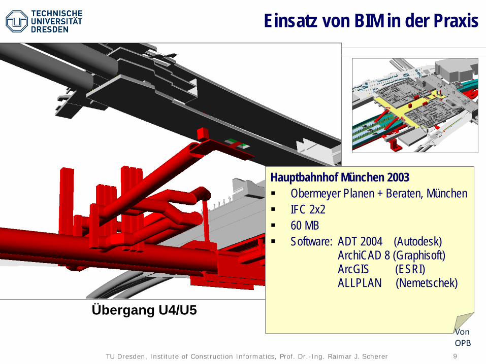
Übergang U4/U5
Hauptbahnhof München 2003 Obermeyer Planen + Beraten, München IFC 2x2 60 MB Software: ADT 2004 (Autodesk)
ArchiCAD 8 (Graphisoft)ArcGIS (ESRI)ALLPLAN (Nemetschek)
Einsatz von BIM in der Praxis
Von OPB

10TU Dresden, Institute of Construction Informatics, Prof. Dr.-Ing. Raimar J. Scherer
AufgangWest
Express-aufzüge
ÜbergangU1 / U2
AufgangOst
AufgangMitte
Das 3D-Modell ist für die Planung und Koordination
Die 2D-Pläne sind zur Bauausführung
Einsatz von BIM in der Praxis
Von OPB
Vom 3D-Modell können unterschiedliche Sichten abgeleitet werden
Integration mit Umgebungsmodell Integration mit 2D-Modell
11TU Dresden, Institute of Construction Informatics, Prof. Dr.-Ing. Raimar J. Scherer
Was soll BIM sein?
12TU Dresden, Institute of Construction Informatics, Prof. Dr.-Ing. Raimar J. Scherer
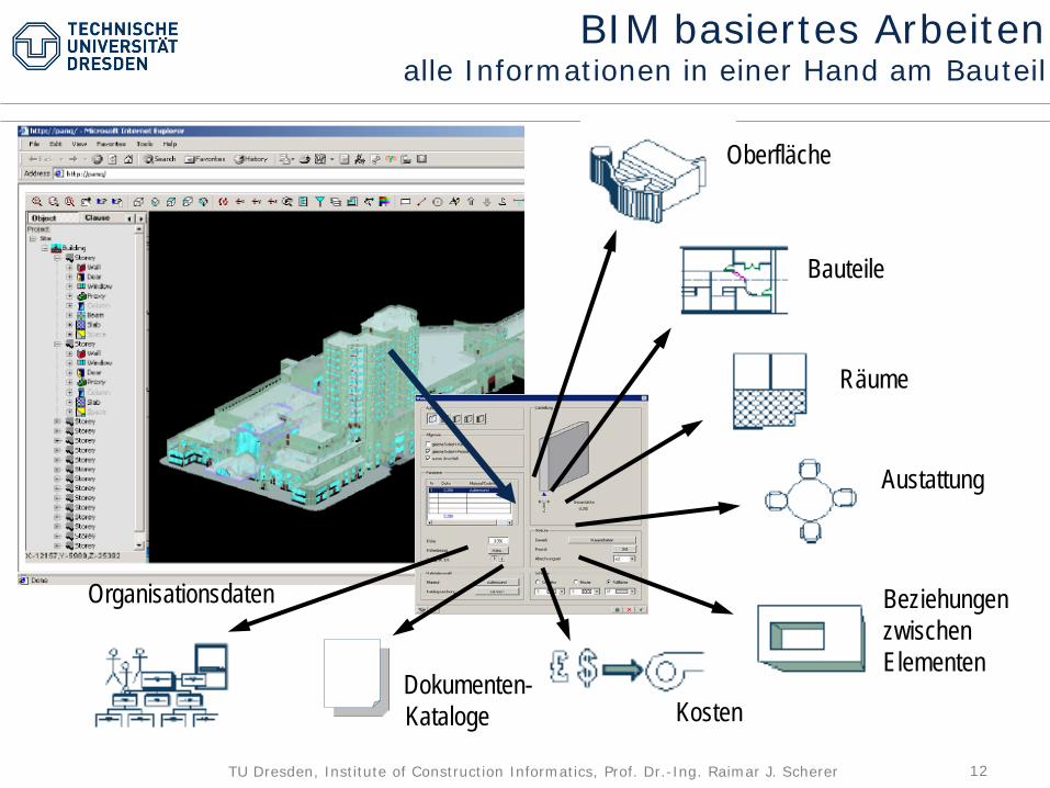
nD GUI
Oberfläche
Bauteile
Räume
Austattung
BeziehungenzwischenElementen
KostenDokumenten-Kataloge
Organisationsdaten
BIM basiertes Arbeitenalle Informationen in einer Hand am Bauteil
13TU Dresden, Institute of Construction Informatics, Prof. Dr.-Ing. Raimar J. Scherer
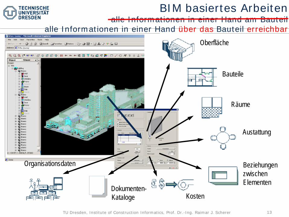
nD GUI
BIM basiertes Arbeitenalle Informationen in einer Hand am Bauteil
alle Informationen in einer Hand über das Bauteil erreichbarOberfläche
Bauteile
Räume
Austattung
BeziehungenzwischenElementen
KostenDokumenten-Kataloge
Organisationsdaten
14TU Dresden, Institute of Construction Informatics, Prof. Dr.-Ing. Raimar J. Scherer
BIM ist die ganzheitliche Arbeitsweise mit allen Informationen des gesamten Baulebenszyklus in strukturierter, digitaler Form.
Raimar Scherer, 2015
Was soll BIM sein
15TU Dresden, Institute of Construction Informatics, Prof. Dr.-Ing. Raimar J. Scherer
BIM ist die ganzheitliche Arbeitsweise mit allen Daten des gesamten Baulebenszyklus in strukturierter, digitaler Form.
In dieser Aussage stecken zwei wesentliche Ansprüche.
Zum einen sollen alle Daten in digitaler Form und damit in digitalen Modellen vorhanden sein,
so dass die Modelle ausgetauscht, modifiziert und zusätzlich durch den Computer, d. h. durch Softwaresysteme geprüft, validiert und mit weiteren Informationen manuell und automatisch angereichert werden können.
Was soll BIM sein

16TU Dresden, Institute of Construction Informatics, Prof. Dr.-Ing. Raimar J. Scherer
BIM ist die ganzheitliche Arbeitsweise mit allen Daten des gesamten Baulebenszyklus in strukturierter, digitaler Form.
In dieser Aussage stecken zwei wesentliche Ansprüche.
Zum anderen soll eine ganzheitliche Arbeitsweise möglich sein.
Dies bedeutet, dass die digitalen Daten, sprich digitale Modelle, miteinander in Verbindung stehen und die Modelle keine singulären Informationsinseln bilden. Die Modelle müssen einerseits interoperabel sein, d. h. ihre Daten müssen gegenseitig austauschbar und vergleichbar sein. Somit müssen gleiche oder gegenseitig überführbare Datenmodelle und Datenformate vorliegen. Die Modelle und damit die Daten müssen andererseits untereinander verlinkt sein, um eineindeutig zu wissen, welche Daten und welche Informationen eine holistische, ganzheitliche Informationseinheit bilden. Erst damit ist sowohl ein anspruchsvolles, effizientes und ganzheitliches Arbeiten mit den Daten und den dazugehörigen Informationen als auch deren Management möglich.
Was ist BIM
17TU Dresden, Institute of Construction Informatics, Prof. Dr.-Ing. Raimar J. Scherer
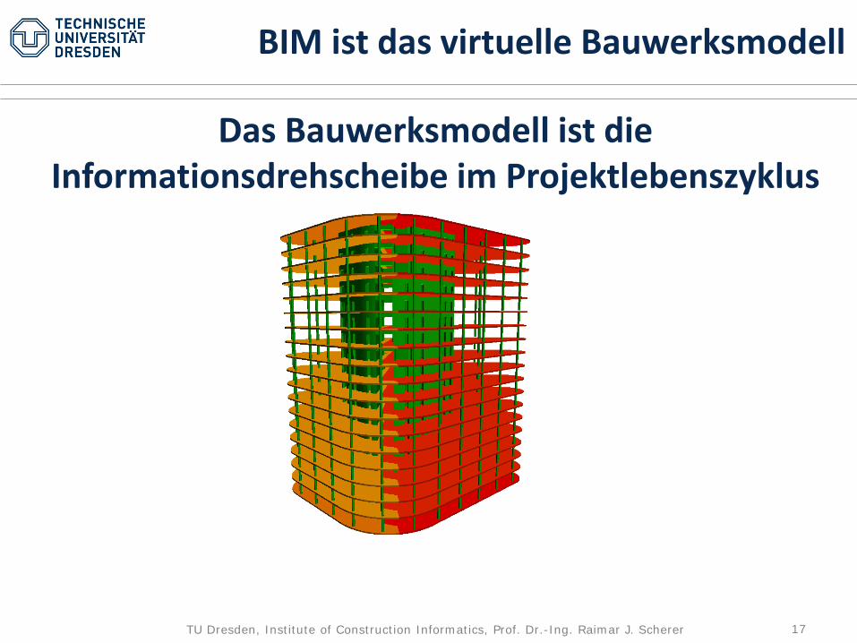
BIM ist das virtuelle Bauwerksmodell
Das Bauwerksmodell ist die Informationsdrehscheibe im Projektlebenszyklus

18TU Dresden, Institute of Construction Informatics, Prof. Dr.-Ing. Raimar J. Scherer
Basisinformation eines BIM Modells
1.
Geometriemodell

19TU Dresden, Institute of Construction Informatics, Prof. Dr.-Ing. Raimar J. Scherer
2.Topologiemodelle
•Räumliche(z.B. Wand – Raum –Geschoss – Bauwerk)
•Zeitliche(Vorgänger –Nachfolger)
•Finanzielle(Finanzierung – Kosten – Rechnung)
•Organisatorische(Bauherr – Architekt –Fachplaner – Behörden – Baufirma –Unterauftragnehmer –Zulieferer)
Basisinformation eines BIM Modells
1.Geometriemodell

20TU Dresden, Institute of Construction Informatics, Prof. Dr.-Ing. Raimar J. Scherer
Basisinformation eines BIM Modells
2.Topologiemodelle
•Räumliche(z.B. Wand – Raum –Geschoss – Bauwerk)
•Zeitliche(Vorgänger –Nachfolger)
•Finanzielle(Finanzierung – Kosten – Rechnung)
•Organisatorische(Bauherr – Architekt –Fachplaner – Behörden – Baufirma –Unterauftragnehmer –Zulieferer)
3.Semantikmodell
Alle Bauteile müssen einen Namen haben
Allgemeingültige Datenstruktur
z.B. Klassenname nach IFC
1.Geometriemodell

21TU Dresden, Institute of Construction Informatics, Prof. Dr.-Ing. Raimar J. Scherer
4.Kataloge:
- Fertigteile- Einbauteile- Fassaden- Techn.
AusbauSemantik?
Basisinformation eines BIM Modells
2.Topologiemodelle
•Räumliche(z.B. Wand – Raum –Geschoss – Bauwerk)
•Zeitliche(Vorgänger –Nachfolger)
•Finanzielle(Finanzierung – Kosten – Rechnung)
•Organisatorische(Bauherr – Architekt –Fachplaner – Behörden – Baufirma –Unterauftragnehmer –Zulieferer)
3.Semantikmodell
Alle Bauteile müssen einen Namen haben
Allgemeingültige Datenstruktur
z.B. Klassenname nach IFC
1.Geometriemodell

22TU Dresden, Institute of Construction Informatics, Prof. Dr.-Ing. Raimar J. Scherer
1. Geometrie (Das ist die Eintrittskarte in BIM)2. Semantik (Bezeichnung, Grundbemusterung, Katalogelemente)3. Topologie (räumlich => Raumbuch)4. Verhalten (erweiterte Semantik, Bemusterung)5. Interoperabilität (Datenformate => Sprachproblem)6. Verlinkung im Modell (Topologien, Gruppierungen) 7. Verlinkung zwischen Modellen (Partnerschaftlich)8. Ontologie (mit Fachwissen schlussfolgern)9. System (Vollständigkeit prüfen => Qualitätskontrolle)10. Modelltransformation (Synchronisation)
Informationsaufbausystem für BIM
Stufe 1
Stufe 2
Stufe 4
Stufe 3

23TU Dresden, Institute of Construction Informatics, Prof. Dr.-Ing. Raimar J. Scherer
Geometrie
24TU Dresden, Institute of Construction Informatics, Prof. Dr.-Ing. Raimar J. Scherer
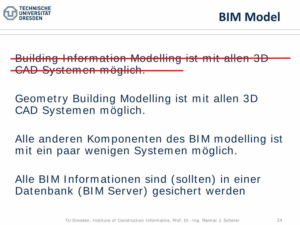
Building Information Modelling ist mit allen 3D CAD Systemen möglich.
Geometry Building Modelling ist mit allen 3D CAD Systemen möglich.
Alle anderen Komponenten des BIM modelling ist mit ein paar wenigen Systemen möglich.
Alle BIM Informationen sind (sollten) in einer Datenbank (BIM Server) gesichert werden
BIM Model

25TU Dresden, Institute of Construction Informatics, Prof. Dr.-Ing. Raimar J. Scherer
Brückenplanung in BIM
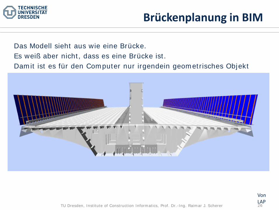
IFC für Brücken gibt es nicht.Eine Brücke kann aber mit der IFC Proxy Klasse modelliert werden (= die semantiklose IFC Klasse)
Von LAP
26TU Dresden, Institute of Construction Informatics, Prof. Dr.-Ing. Raimar J. Scherer
Brückenplanung in BIM
Das Modell sieht aus wie eine Brücke.Es weiß aber nicht, dass es eine Brücke ist.Damit ist es für den Computer nur irgendein geometrisches Objekt
Von LAP

27TU Dresden, Institute of Construction Informatics, Prof. Dr.-Ing. Raimar J. Scherer
Gebäudeplanung in BIMIFC Gebäude gibt es => ein Sematikmodell kann erstellt werden.Der Computer weiß exakt was für ein Gebäude es ist und welche Elemente es besitzt.Der Computer kann für Sie tätig werden
Junge Semperoper, Dresden
Von LAP

28TU Dresden, Institute of Construction Informatics, Prof. Dr.-Ing. Raimar J. Scherer
Initial stream linesStream lines lower level
Stream lines upper level
The computer can do an indoor CFD simulation for you – and much more

29TU Dresden, Institute of Construction Informatics, Prof. Dr.-Ing. Raimar J. Scherer13.09.2017
iVEL- integrated Virtual Engineering LabAutomatische Analysen aus dem BIM Modell
IntegratedDesign Cycle
IntegratedAnalysis
Cycle
BIMManagement
System- Filter, Mapper,….
NumericalEngineering
AnalysisManager
- FEM,..
Modeller - CAD, Viewer

30TU Dresden, Institute of Construction Informatics, Prof. Dr.-Ing. Raimar J. Scherer13.09.2017
(5) domain model repositories
(9) simulation management
(7) collaboration manager, (8) platform kernel (10) numerical analysis management
IntegratedDesign Cycle
IntegratedAnalysis
Cycle
(1) Modelling, (2) Management
(3) Inspection(4) Control
(6) BIM data management
BIMManagement
System- Filter, Mapper,….
NumericalEngineering
AnalysisManager
- FEM,..
iVEL- integrated Virtual Engineering LabAutomatische Analysen aus dem BIM Modell

31TU Dresden, Institute of Construction Informatics, Prof. Dr.-Ing. Raimar J. Scherer13.09.2017
IntegratedDesign Cycle
IntegratedAnalysis
Cycle
BIMManagement
System- Filter, Mapper,….
NumericalEngineering
AnalysisManager
- FEM,..KPI Überprüfung
Modeller - CAD, Viewer
Gesteuert mit KPI
iVEL- integrated Virtual Engineering Labentwickelt zum BIM Design Lab
32TU Dresden, Institute of Construction Informatics, Prof. Dr.-Ing. Raimar J. Scherer
Semantik
Die Sprache der virtuellen Welt

33TU Dresden, Institute of Construction Informatics, Prof. Dr.-Ing. Raimar J. Scherer
Kein freies Modellieren mehr möglich. Die Eingabe aller Bauwerkselemente erfolgt über vorgegebene Begriffe.
Die Eingabe der Semantik erfolgt i.d.R. zusammen mit der Geometrieeingabe.
Nur wenige CAD Programme weltweit sprechen eine einheitliche Sprache (Semantik).
Die Baucomputersprache heißt IFCSie ist genormt in der ISO 16739+und wird ergänzt durch GAEB, das es nur in Deutschland gibt
Semantikmodell
34TU Dresden, Institute of Construction Informatics, Prof. Dr.-Ing. Raimar J. Scherer
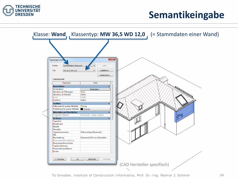
Klasse: Wand Klassentyp: MW 36,5 WD 12,0 (= Stammdaten einer Wand)
(CAD Hersteller spezifisch)
Semantikeingabe

35TU Dresden, Institute of Construction Informatics, Prof. Dr.-Ing. Raimar J. Scherer
Klasse: Wand Klassentyp: MW 36,5 WD 12,0 (= Stammdaten einer Wand)
(CAD Hersteller spezifisch)
Semantikeingabe
Wand ist eine IFC KlasseMW 36,5 WD 12,0 ist die weitere Spezialisierung der Klasse Wand in Unterklassen.
Dies ist in IFC durch die Klasse Klassentyp realisiert. Klassentype ist eine allgemeine Klasse deren Benennung bei der Verwendung durch den Anwender festgelegt wird. Dieser Name ist damit nicht Bestandteil der Sprache IFC und damit für andere nicht bekannt, d.h. ohne Bedeutung.Eine Standardisierung solche Klassentypen könnte über Industrievereinigungen oder Herstellerkataloge erfolgen. Der Anwender würde dann aus vorgegebenen Listen, die Industriestandards bilden, auswählen.

36TU Dresden, Institute of Construction Informatics, Prof. Dr.-Ing. Raimar J. Scherer
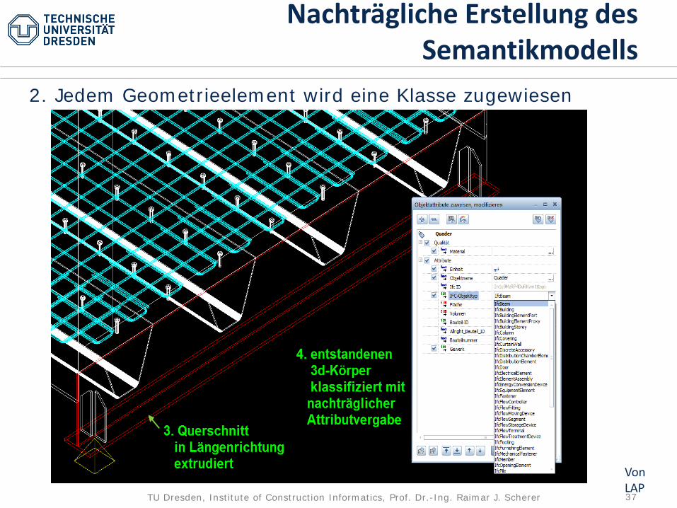
Nachträgliche Erstellung des Semantikmodells
Von LAP
1. Eingabe der Elemente als reine Geometrieelemente mit ifcProxy
37TU Dresden, Institute of Construction Informatics, Prof. Dr.-Ing. Raimar J. Scherer
2. Jedem Geometrieelement wird eine Klasse zugewiesen
Nachträgliche Erstellung des Semantikmodells
Von LAP
38TU Dresden, Institute of Construction Informatics, Prof. Dr.-Ing. Raimar J. Scherer
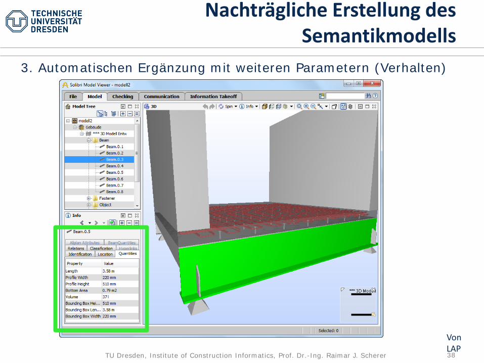
3. Automatischen Ergänzung mit weiteren Parametern (Verhalten)
Nachträgliche Erstellung des Semantikmodells
Von LAP
39TU Dresden, Institute of Construction Informatics, Prof. Dr.-Ing. Raimar J. Scherer
Verhalten
40TU Dresden, Institute of Construction Informatics, Prof. Dr.-Ing. Raimar J. Scherer
Festlegen des Verhaltens durch Eingabe weiterer Parameter
Bspw. Eingabe der Materialeigenschaften des thermischen oder tragenden Verhaltens oder die Kosteneigenschaften, wie Aufwandswerte und Einheitskosten
Verhalten

41TU Dresden, Institute of Construction Informatics, Prof. Dr.-Ing. Raimar J. Scherer
z.B. der Tragfähigkeit in Form von Bewehrungsinformationen
Eingabe von Verhaltensinformationen
(aus Autodesk Revit)
42TU Dresden, Institute of Construction Informatics, Prof. Dr.-Ing. Raimar J. Scherer
Topologie
43TU Dresden, Institute of Construction Informatics, Prof. Dr.-Ing. Raimar J. Scherer
Für die organisierte Verwaltung ist es wichtig, dass alle Bauteile Räumen zugeordnet werden.
Mehrere Räume bilden ein Stockwerk.
Mehrere Stockwerke bilden das Gebäude
Daneben gibt es noch weitere, wichtige organisatorische Zuordnungen, s. Verlinken
Topologie

44TU Dresden, Institute of Construction Informatics, Prof. Dr.-Ing. Raimar J. Scherer
(aus einem Markt CAD)
Topologie
Die umschließenden Wände und Decken bilden das Objekt Raum.Das Objekt Raum ist die Verlinkung zum Raumbuch.
45TU Dresden, Institute of Construction Informatics, Prof. Dr.-Ing. Raimar J. Scherer
(aus einem Markt CAD)
Topologie
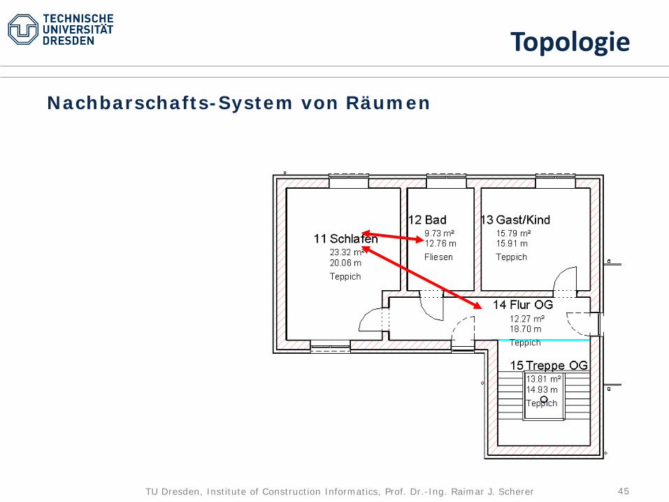
Nachbarschafts-System von Räumen
46TU Dresden, Institute of Construction Informatics, Prof. Dr.-Ing. Raimar J. Scherer
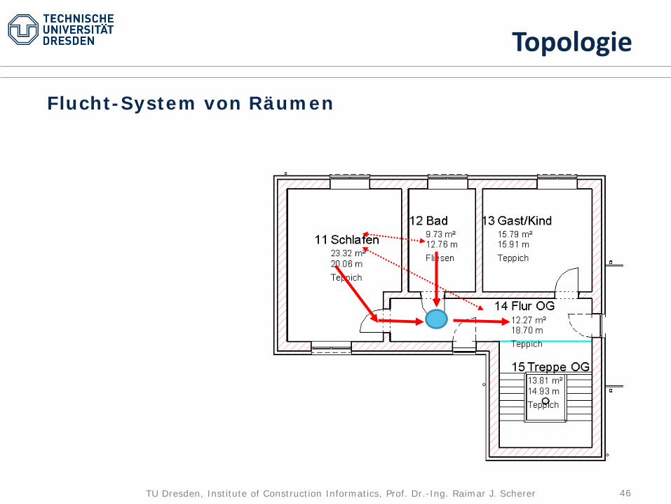
(aus einem Markt CAD)
Topologie
Flucht-System von Räumen
47TU Dresden, Institute of Construction Informatics, Prof. Dr.-Ing. Raimar J. Scherer
Verlinkung

48TU Dresden, Institute of Construction Informatics, Prof. Dr.-Ing. Raimar J. Scherer
Mo Di Mi Do Fr Sa So
€Leistungsmodell
Terminmodell
Gebäudemodell
BIM sind mehrere Modelle - 5D
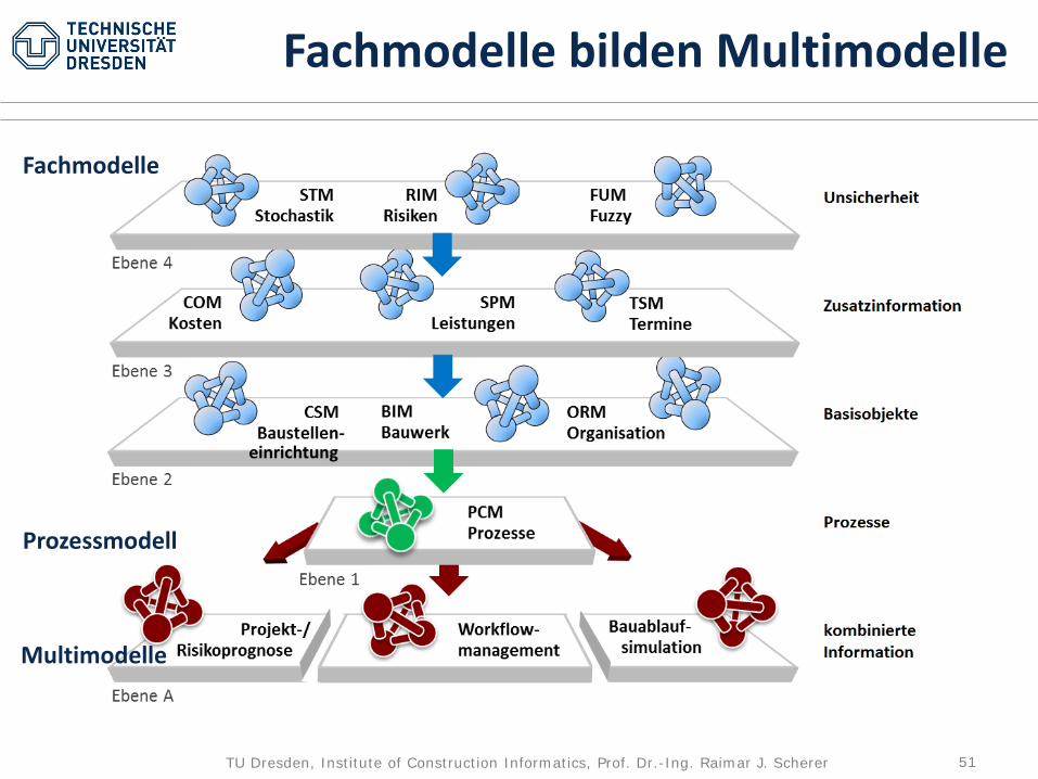
Alle nur denkbaren Informationen in ein Modell zu legen, führt zu einem nicht mehr beherrschbaren Informationswust.
Informationen sind in Fachmodelle zu bündeln sind von Fachpersonen zu pflegen sind einer eindeutigen
Verantwortung zu unterstellen.
Das virtuelle Gebäude wird i.d.R. als Informationsdrehscheibe benutzt
49TU Dresden, Institute of Construction Informatics, Prof. Dr.-Ing. Raimar J. Scherer
Mo Di Mi Do Fr Sa So
€Leistungsmodell
Terminmodell
Gebäudemodell
Linkmodell
Multimodell
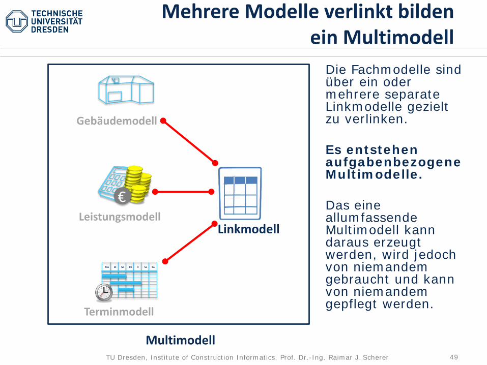
Mehrere Modelle verlinkt bilden ein Multimodell
Die Fachmodelle sind über ein oder mehrere separate Linkmodelle gezielt zu verlinken.
Es entstehen aufgabenbezogene Multimodelle.
Das eine allumfassende Multimodell kann daraus erzeugt werden, wird jedoch von niemandem gebraucht und kann von niemandem gepflegt werden.
50TU Dresden, Institute of Construction Informatics, Prof. Dr.-Ing. Raimar J. Scherer
Mo Di Mi Do Fr Sa So
€Leistungsmodell
Terminmodell
Gebäudemodell
Linkmodell
Multimodell
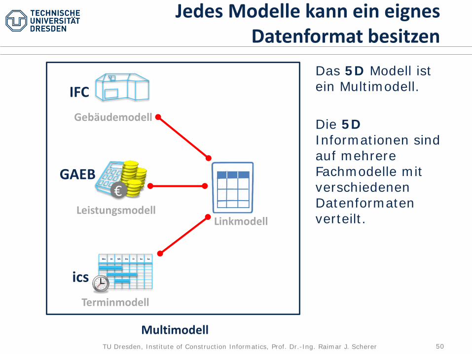
Jedes Modelle kann ein eignes Datenformat besitzen
IFC
GAEB
ics
Das 5D Modell ist ein Multimodell.
Die 5DInformationen sind auf mehrere Fachmodelle mit verschiedenen Datenformaten verteilt.
51TU Dresden, Institute of Construction Informatics, Prof. Dr.-Ing. Raimar J. Scherer
Fachmodelle bilden Multimodelle
Fachmodelle
Prozessmodell
Multimodelle

52TU Dresden, Institute of Construction Informatics, Prof. Dr.-Ing. Raimar J. Scherer
Modellzustände
LODLevel of Detail
LoDLevel of Development
53TU Dresden, Institute of Construction Informatics, Prof. Dr.-Ing. Raimar J. Scherer
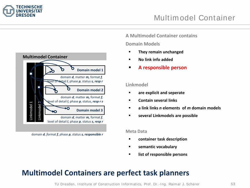
Multimodel Container
Domain model 2
Domain model 1
Domain model 3
Multimodel Container
domain d, matter m, format f, level of detail l, phase p, status s, resp r
domain d, matter m, format f, level of detail l, phase p, status, resp r s
domain d, matter m, format f, level of detail l, phase p, status s, resp r
domain d, format f, phase p, status s, responsible r
Link
mod
el 2
A Multimodel Container containsDomain Models They remain unchanged
No link info added
A responsible person
Linkmodel are explicit and seperate
Contain several links
a link links n elements of m domain models
several Linkmodels are possible
Meta Data container task description
semantic vocabulary
list of responsible persons
Link
mod
ell
Link
mod
el 1
Multimodel Containers are perfect task planners

54TU Dresden, Institute of Construction Informatics, Prof. Dr.-Ing. Raimar J. Scherer
A Multimodel querry
Multimodels are going to become a buildingSMART and an ISO standard.
Provide the price of the column of story 16 errected on 21.06.2013
Not several querries are necessary but only oneand an automatic search in several models will happen
55TU Dresden, Institute of Construction Informatics, Prof. Dr.-Ing. Raimar J. Scherer
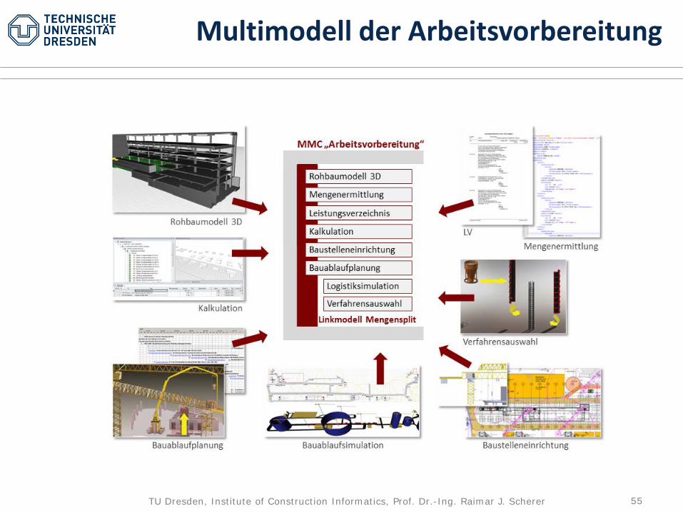
Multimodell der Arbeitsvorbereitung
56TU Dresden, Institute of Construction Informatics, Prof. Dr.-Ing. Raimar J. Scherer
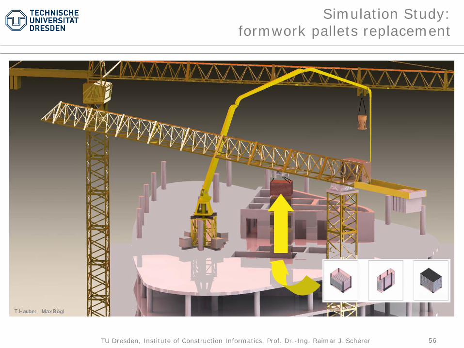
Simulation Study: formwork pallets replacement
57TU Dresden, Institute of Construction Informatics, Prof. Dr.-Ing. Raimar J. Scherer
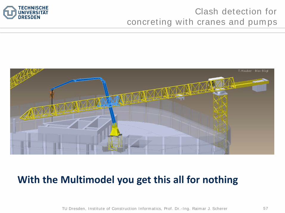
Clash detection for concreting with cranes and pumps
With the Multimodel you get this all for nothing

58TU Dresden, Institute of Construction Informatics, Prof. Dr.-Ing. Raimar J. Scherer
Composition of a cranefrom crane library of components
Who will provide this equipement catalog?
59TU Dresden, Institute of Construction Informatics, Prof. Dr.-Ing. Raimar J. Scherer
BIM für Umbau und
Ertüchtigung
benötigt einen neuen
Arbeitsprozess zum
Aufbau eines BIM
60TU Dresden, Institute of Construction Informatics, Prof. Dr.-Ing. Raimar J. Scherer
BIM for Retrofitting
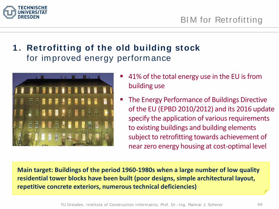
41% of the total energy use in the EU is frombuilding use
The Energy Performance of Buildings Directive of the EU (EPBD 2010/2012) and its 2016 update specify the application of various requirements to existing buildings and building elements subject to retrofitting towards achievement of near zero energy housing at cost-optimal level
1. Retrofitting of the old building stock for improved energy performance
Main target: Buildings of the period 1960-1980s when a large number of low quality residential tower blocks have been built (poor designs, simple architectural layout, repetitive concrete exteriors, numerous technical deficiencies)

61TU Dresden, Institute of Construction Informatics, Prof. Dr.-Ing. Raimar J. Scherer
BIM for Retrofitting
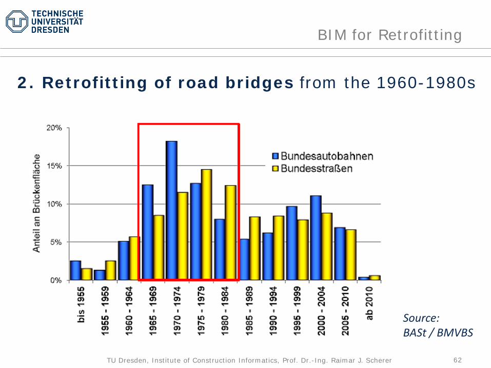
2. Retrofitting of road bridges from the 1960-1980s
Example Germany Number of bridges : 39,106 Total length: 2,089,020 m Total area: 30,033,018 m2
62TU Dresden, Institute of Construction Informatics, Prof. Dr.-Ing. Raimar J. Scherer
BIM for Retrofitting
Source:BASt / BMVBS
2. Retrofitting of road bridges from the 1960-1980s

63TU Dresden, Institute of Construction Informatics, Prof. Dr.-Ing. Raimar J. Scherer
BIM for Retrofitting
~40% require urgently retrofitting measureswith another nearly 40%to join soon
2. Retrofitting of road bridges from the 1960-1980s
64TU Dresden, Institute of Construction Informatics, Prof. Dr.-Ing. Raimar J. Scherer
BIM for Retrofitting
Efficient retrofitting (or refurbishment) strategies require a solid information basis about the facility and its past and future use, including the expected usage behaviour in the planned new technological environment. Such an information basis can be provided by BIM

65TU Dresden, Institute of Construction Informatics, Prof. Dr.-Ing. Raimar J. Scherer
BIM for Retrofitting
Efficient retrofitting (or refurbishment) strategies require a solid information basis about the facility and its past and future use, including the expected usage behaviour in the planned new technological environment. Such an information basis can be provided by BIM
66TU Dresden, Institute of Construction Informatics, Prof. Dr.-Ing. Raimar J. Scherer
BIM for Retrofitting
Efficient retrofitting (or refurbishment) strategies require a solid information basis about the facility and its past and future use, including the expected usage behaviour in the planned new technological environment.
Unfortunately, for most existing facilities BIM documentation does not exist.
Therefore, it is necessary to first create the BIM model of the facility, correctly interpreting its actual state.
67TU Dresden, Institute of Construction Informatics, Prof. Dr.-Ing. Raimar J. Scherer
The BIMification Process
68TU Dresden, Institute of Construction Informatics, Prof. Dr.-Ing. Raimar J. Scherer
BIM for Retrofitting
Definition BIMification is the process to obtain from an
existing real facility a 3D BIM, preferably based on the standard ISO 16739 data schema (IFC), while taking into account the actual state and performance parameters of the facility
Note BIMification is more than just
(re-)constructing the model from old 2D drawings or laser point clouds

69TU Dresden, Institute of Construction Informatics, Prof. Dr.-Ing. Raimar J. Scherer
The BIMification Process
Three-stage design process of existing buildings is
Anamnesis – Diagnosis – Therapy (ADT)
adapting and redefining a contemporary approach for the rehabilitation of cultural heritage(see: van Balen & Vestringe, 2016: Structural Analysis of Historical Constructions: Anamnesis, Diagnosis, Therapy, Controls; Proc. 10th Int. Conference on Structural Analysis of Historical Constructions, Leuven, Belgium, 13-15 Sep. 2016)
Anamnesis Diagnosis Therapy
InspectionSemantic Model
Building System Behaviour Rehabilitation StrategiesRetrofitting AlternativesDecision Making
BIMification BIM

70TU Dresden, Institute of Construction Informatics, Prof. Dr.-Ing. Raimar J. Scherer
AnamnesisDiagnosis
Therapy
BIMification BIM
GeoNeighborhood
ElementBehavior
Gap
Variability
PotentialAlternatives
Decision FinalDetailing
NewMethods
A1A2
A3
D1
D2
T1T2
T3T4
A4
basic advanced extended
Enhanced Methods
Enhanced Methods
BIMification and BIM process for building renovation defining the ADT processes

71TU Dresden, Institute of Construction Informatics, Prof. Dr.-Ing. Raimar J. Scherer
AnamnesisDiagnosis
Therapy
BIMification BIM
GeoNeighborhood
ElementBehavior
Gap
Variability
PotentialAlternatives
Decision FinalDetailing
NewMethods
A1A2
A3
D1
D2
T1T2
T3T4
A4
basic advanced extended
Enhanced Methods
Enhanced Methods
Controll
BIMC
BIMification and BIM and CPS process for buildings defining the ADTC processes
• robust• nachhaltig• …• …
BIM EntwurfundBIM AusführungBIM FM
72TU Dresden, Institute of Construction Informatics, Prof. Dr.-Ing. Raimar J. Scherer
The BIMification Process
The Result of implementing the suggested process will be
a BIM Retrofitting Lab

73TU Dresden, Institute of Construction Informatics, Prof. Dr.-Ing. Raimar J. Scherer
Anamnesis
74TU Dresden, Institute of Construction Informatics, Prof. Dr.-Ing. Raimar J. Scherer
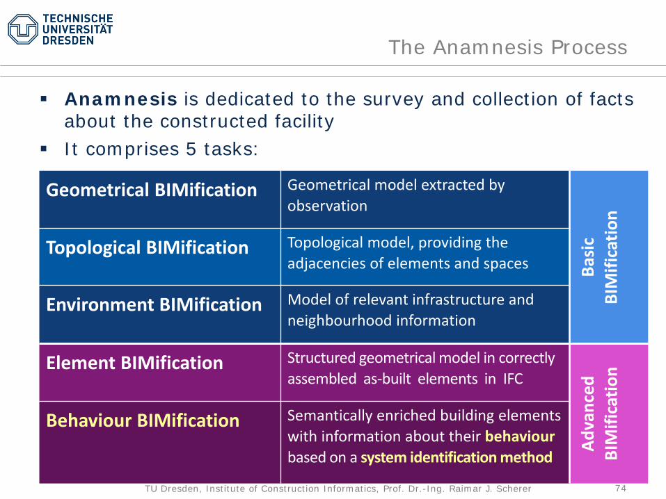
The Anamnesis Process
Anamnesis is dedicated to the survey and collection of facts about the constructed facility
It comprises 5 tasks:
Geometrical BIMification Geometrical model extracted by observation
Basi
c BI
Mifi
catio
n
Topological BIMification Topological model, providing the adjacencies of elements and spaces
Environment BIMification Model of relevant infrastructure and neighbourhood information
Element BIMification Structured geometrical model in correctly assembled as-built elements in IFC
Adva
nced
BIM
ifica
tion
Behaviour BIMification Semantically enriched building elements with information about their behaviourbased on a system identification method

75TU Dresden, Institute of Construction Informatics, Prof. Dr.-Ing. Raimar J. Scherer
The Anamnesis Processin Building Energy Performance Retrofitting
Using Point Cloud Data from 3D Laser Scanning
Source: TrueCADDEducational Centre, London, UK
Laser Point Cloud
Geometricalmodel

76TU Dresden, Institute of Construction Informatics, Prof. Dr.-Ing. Raimar J. Scherer
The Anamnesis Processin Building Energy Performance Retrofitting
Source: Sahin C. (2915): Planar segmentation of indoor terrestrial laser scanning point clouds viadistance function from a point to a plane,Optics and Lasers in Engineering 01/2015
Automated geometric reconstruction of office data set
(1) point cloudsegmentation
(2) topologyprimitives
(3) inducedcell complex
(4) wireframe model& overlaid point cloud (5) final 3D model
77TU Dresden, Institute of Construction Informatics, Prof. Dr.-Ing. Raimar J. Scherer
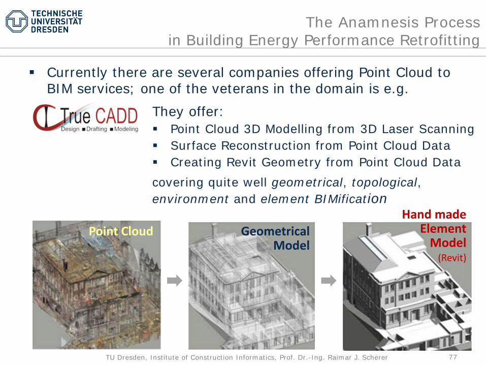
The Anamnesis Processin Building Energy Performance Retrofitting
Currently there are several companies offering Point Cloud to BIM services; one of the veterans in the domain is e.g.
They offer: Point Cloud 3D Modelling from 3D Laser Scanning Surface Reconstruction from Point Cloud Data Creating Revit Geometry from Point Cloud Datacovering quite well geometrical, topological, environment and element BIMification
Point Cloud GeometricalModel
Hand madeElement
Model(Revit)
78TU Dresden, Institute of Construction Informatics, Prof. Dr.-Ing. Raimar J. Scherer
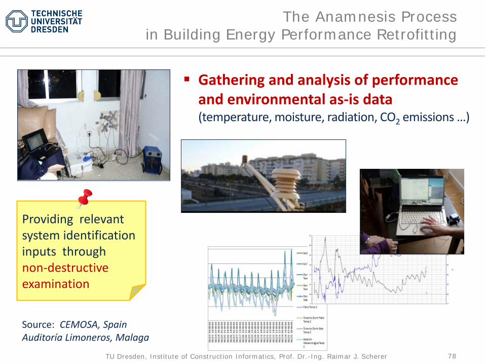
The Anamnesis Processin Building Energy Performance Retrofitting
Gathering and analysis of performance and environmental as-is data(temperature, moisture, radiation, CO2 emissions …)
Source: CEMOSA, Spain Auditoría Limoneros, Malaga
Providing relevant system identification inputs throughnon-destructiveexamination

79TU Dresden, Institute of Construction Informatics, Prof. Dr.-Ing. Raimar J. Scherer
Unknown information is provided viaknowledge templates (materials used,element composition, façade and roof construction, insulations, MEP system parameters etc.)
Greyhound model approach combininga simplified physical system with a datamining method
The Anamnesis Processin Building Energy Performance Retrofitting
Draft Building Model with appropriately identified building elements (Element BIMification)

80TU Dresden, Institute of Construction Informatics, Prof. Dr.-Ing. Raimar J. Scherer
The Anamnesis Processin Building Energy Performance Retrofitting
BIM-CAD BIMAnnotator
KnowledgeTemplatesRetrieval
OntologyGenerator
SimulationModel
Mapping
Geometrical to Element BIMification
Semantic model enrichment & model transformation (BIM to SIM)
81TU Dresden, Institute of Construction Informatics, Prof. Dr.-Ing. Raimar J. Scherer
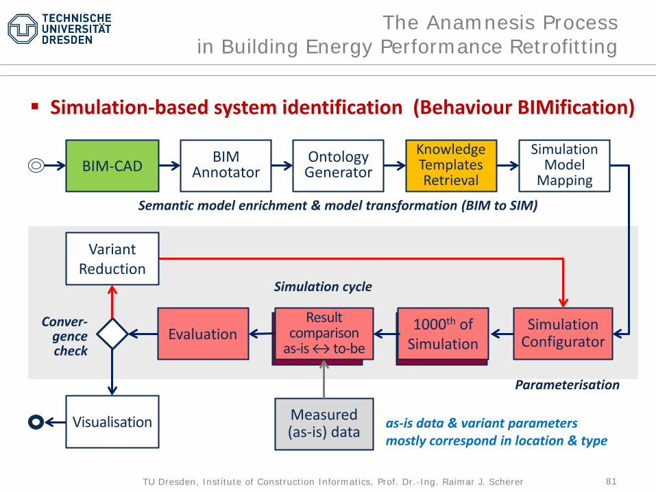
The Anamnesis Processin Building Energy Performance Retrofitting
BIM-CAD
SimulationConfigurator
Visualisation
1000th ofSimulationEvaluation
Measured(as-is) data
VariantReduction
Result comparison
as-is ↔ to-be
BIMAnnotator
KnowledgeTemplatesRetrieval
OntologyGenerator
SimulationModel
Mapping
Simulation-based system identification (Behaviour BIMification)
Semantic model enrichment & model transformation (BIM to SIM)
Parameterisation
as-is data & variant parametersmostly correspond in location & type
Simulation cycle
Conver-gencecheck

82TU Dresden, Institute of Construction Informatics, Prof. Dr.-Ing. Raimar J. Scherer
The Anamnesis Processin Bridge Retrofitting
Inspecting the bridge structure Studying existing drawings
Sources: LAP, GermanyBranch office Dresden& TU Dresden
83TU Dresden, Institute of Construction Informatics, Prof. Dr.-Ing. Raimar J. Scherer
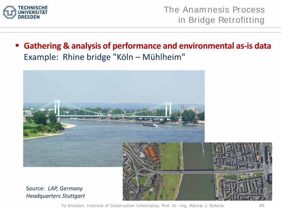
The Anamnesis Processin Bridge Retrofitting
Gathering & analysis of performance and environmental as-is dataExample: Rhine bridge "Köln – Mühlheim"
Source: LAP, GermanyHeadquarters Stuttgart
84TU Dresden, Institute of Construction Informatics, Prof. Dr.-Ing. Raimar J. Scherer
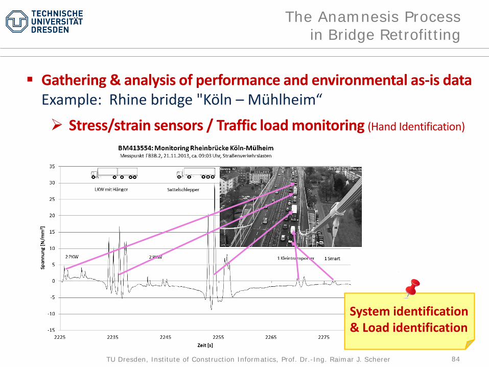
The Anamnesis Processin Bridge Retrofitting
Gathering & analysis of performance and environmental as-is dataExample: Rhine bridge "Köln – Mühlheim“ Stress/strain sensors / Traffic load monitoring (Hand Identification)
System identification& Load identification

85TU Dresden, Institute of Construction Informatics, Prof. Dr.-Ing. Raimar J. Scherer
The Anamnesis Processin Bridge Retrofitting
Gathering & analysis of performance and environmental as-is dataExample: Rhine bridge "Köln – Mühlheim“ Dedicated load tests for model calibration Vollsperrung der Brücke notwendig
86TU Dresden, Institute of Construction Informatics, Prof. Dr.-Ing. Raimar J. Scherer
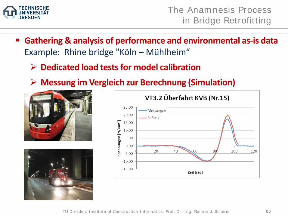
The Anamnesis Processin Bridge Retrofitting
Gathering & analysis of performance and environmental as-is dataExample: Rhine bridge "Köln – Mühlheim“ Dedicated load tests for model calibration Messung im Vergleich zur Berechnung (Simulation)
87TU Dresden, Institute of Construction Informatics, Prof. Dr.-Ing. Raimar J. Scherer
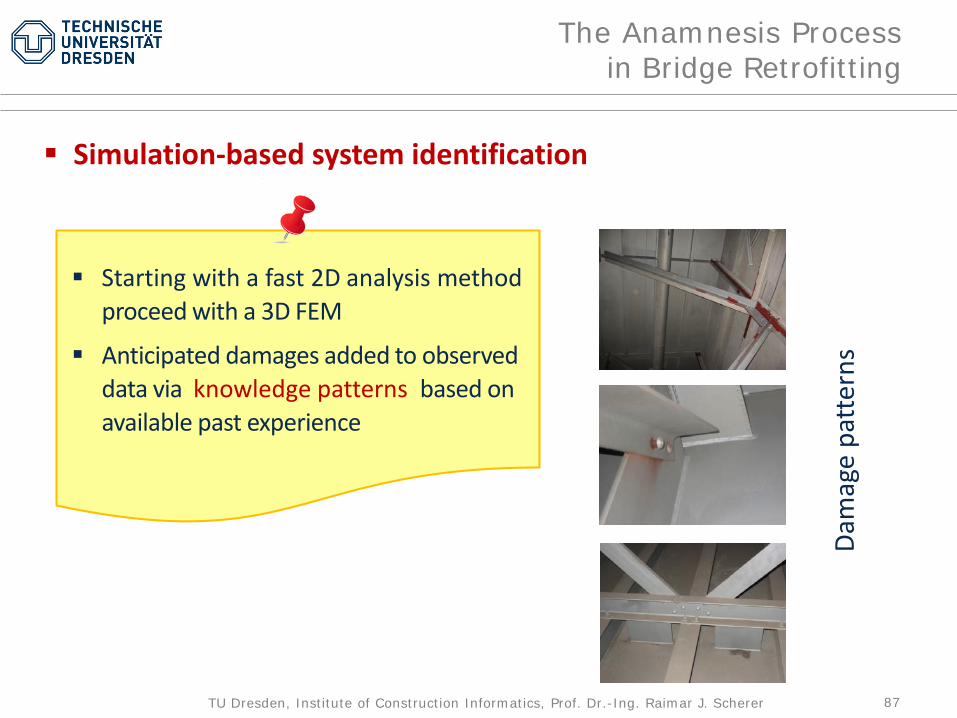
The Anamnesis Processin Bridge Retrofitting
Simulation-based system identification
Starting with a fast 2D analysis methodproceed with a 3D FEM
Anticipated damages added to observed data via knowledge patterns based on available past experience
Dam
age
patt
erns
88TU Dresden, Institute of Construction Informatics, Prof. Dr.-Ing. Raimar J. Scherer
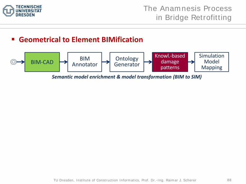
The Anamnesis Processin Bridge Retrofitting
BIM-CAD BIMAnnotator
Knowl.-baseddamagepatterns
OntologyGenerator
SimulationModel
Mapping
Geometrical to Element BIMification
Semantic model enrichment & model transformation (BIM to SIM)

89TU Dresden, Institute of Construction Informatics, Prof. Dr.-Ing. Raimar J. Scherer
The Anamnesis Processin Bridge Retrofitting
BIM-CAD
SimulationConfigurator
Visualisation
Evaluation
Monitored(as-is) data
VariantReduction
Result comparison
as-is ↔ to-be
BIMAnnotator
Knowl.-baseddamagepatterns
OntologyGenerator
SimulationModel
Mapping
Simulation-based system identification (Behaviour BIMification)
Semantic model enrichment & model transformation (BIM to SIM)
Parameterisation
as-is data & variant parametersdiffer in location and type!
Simulation cycle
Conver-gencecheck
1000th ofSimulation
90TU Dresden, Institute of Construction Informatics, Prof. Dr.-Ing. Raimar J. Scherer
Diagnosis
91TU Dresden, Institute of Construction Informatics, Prof. Dr.-Ing. Raimar J. Scherer
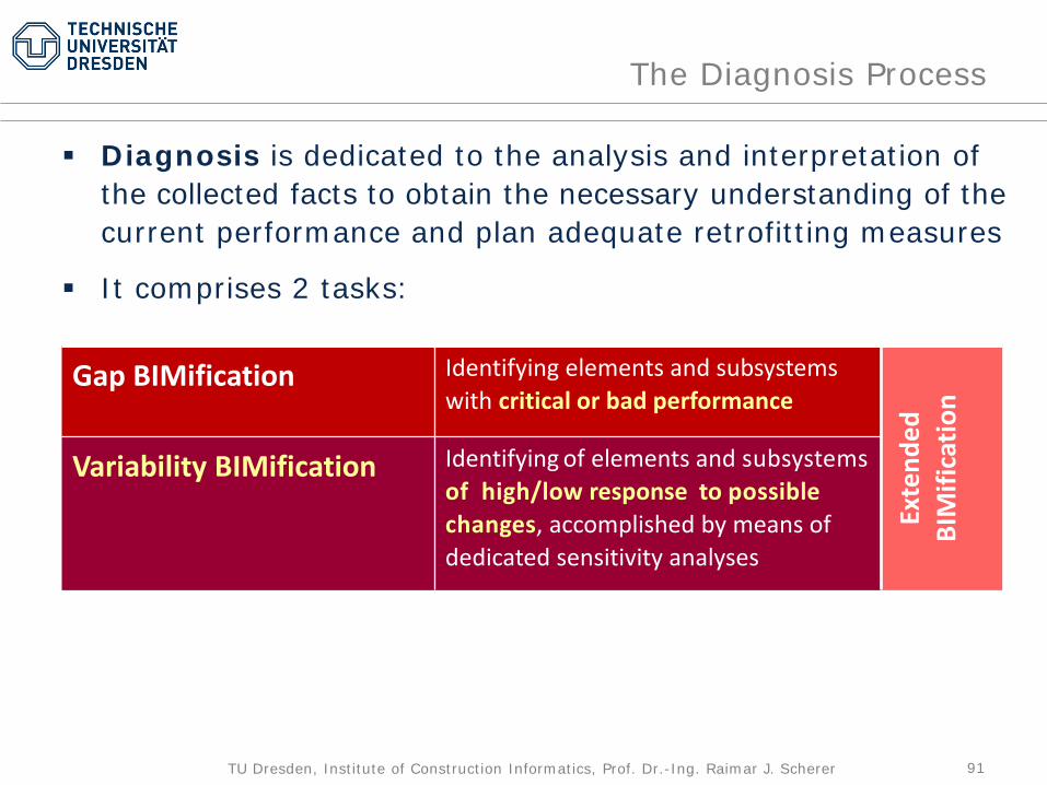
The Diagnosis Process
Diagnosis is dedicated to the analysis and interpretation of the collected facts to obtain the necessary understanding of the current performance and plan adequate retrofitting measures
It comprises 2 tasks:
Gap BIMification Identifying elements and subsystems with critical or bad performance
Exte
nded
BIM
ifica
tion
Variability BIMification Identifying of elements and subsystems of high/low response to possiblechanges, accomplished by means of dedicated sensitivity analyses
92TU Dresden, Institute of Construction Informatics, Prof. Dr.-Ing. Raimar J. Scherer
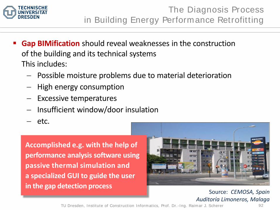
The Diagnosis Processin Building Energy Performance Retrofitting
Gap BIMification should reveal weaknesses in the construction of the building and its technical systemsThis includes:− Possible moisture problems due to material deterioration− High energy consumption− Excessive temperatures− Insufficient window/door insulation− etc.
Source: CEMOSA, Spain Auditoría Limoneros, Malaga
Accomplished e.g. with the help ofperformance analysis software usingpassive thermal simulation anda specialized GUI to guide the userin the gap detection process

93TU Dresden, Institute of Construction Informatics, Prof. Dr.-Ing. Raimar J. Scherer
The Diagnosis Processin Building Energy Performance Retrofitting
Detecting operative temperature problems on zone level

94TU Dresden, Institute of Construction Informatics, Prof. Dr.-Ing. Raimar J. Scherer
The Diagnosis Processin Building Energy Performance Retrofitting
Source: EU Project ISESYoung Opera HouseDresden, Germany
Detecting heat conductiongains on zone level

95TU Dresden, Institute of Construction Informatics, Prof. Dr.-Ing. Raimar J. Scherer
The Diagnosis Processin Building Energy Performance Retrofitting
Source: T. Grillo, itemlive.com, 26 July 2016 (left)A. Perschk & Schünemann C., TU Dresden,Internal Report, 2015 (right)
Detecting gaps by means ofthermographic analysis usinga thermal camera
96TU Dresden, Institute of Construction Informatics, Prof. Dr.-Ing. Raimar J. Scherer
The Diagnosis Processin Building Energy Performance Retrofitting
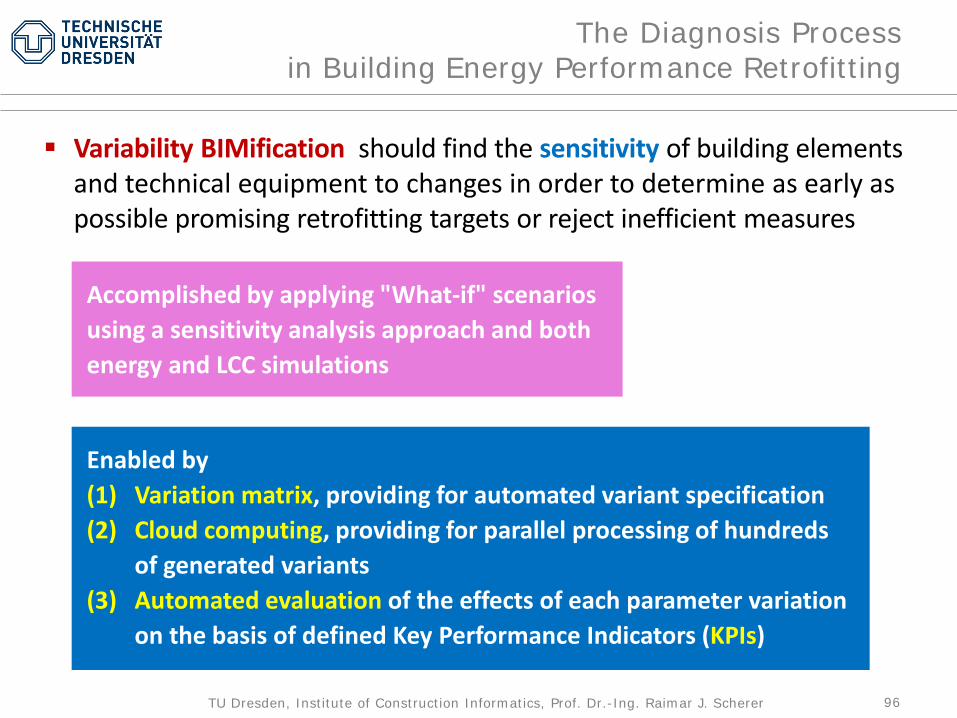
Variability BIMification should find the sensitivity of building elementsand technical equipment to changes in order to determine as early as possible promising retrofitting targets or reject inefficient measures
Accomplished by applying "What-if" scenarios using a sensitivity analysis approach and bothenergy and LCC simulations
Enabled by (1) Variation matrix, providing for automated variant specification(2) Cloud computing, providing for parallel processing of hundreds
of generated variants(3) Automated evaluation of the effects of each parameter variation
on the basis of defined Key Performance Indicators (KPIs)
97TU Dresden, Institute of Construction Informatics, Prof. Dr.-Ing. Raimar J. Scherer
The Diagnosis Processin Building Energy Performance Retrofitting
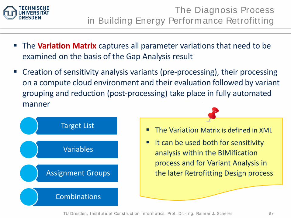
The Variation Matrix captures all parameter variations that need to be examined on the basis of the Gap Analysis result
Creation of sensitivity analysis variants (pre-processing), their processing on a compute cloud environment and their evaluation followed by variant grouping and reduction (post-processing) take place in fully automated manner
Target List
Variables
Assignment Groups
Combinations
The Variation Matrix is defined in XML
It can be used both for sensitivity analysis within the BIMification process and for Variant Analysis in the later Retrofitting Design process
98TU Dresden, Institute of Construction Informatics, Prof. Dr.-Ing. Raimar J. Scherer
The Diagnosis Processin Building Energy Performance Retrofitting
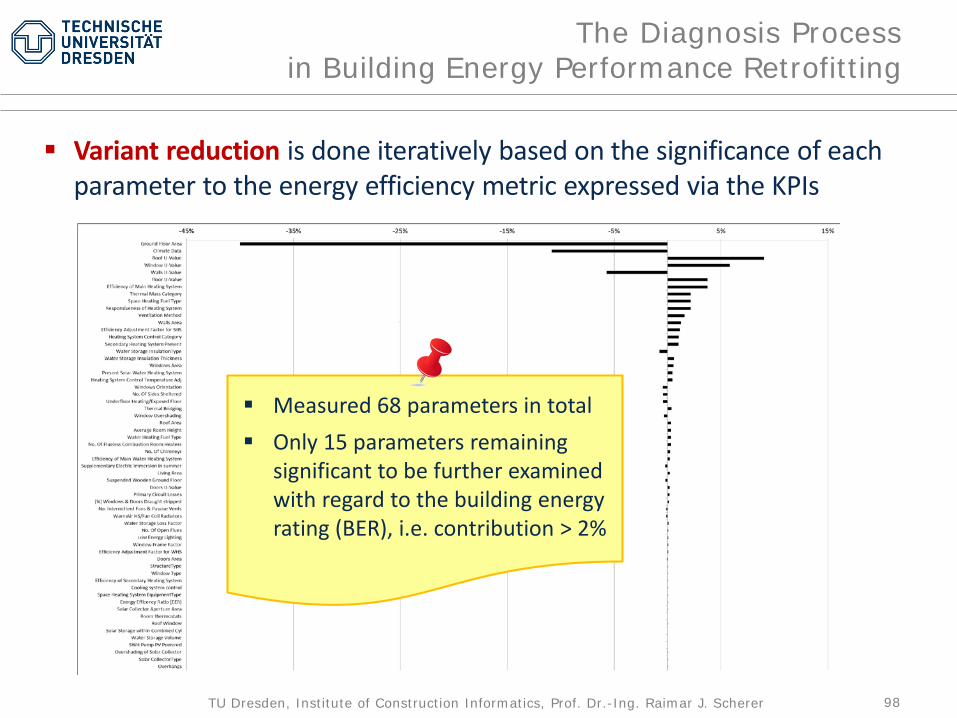
Variant reduction is done iteratively based on the significance of eachparameter to the energy efficiency metric expressed via the KPIs
Measured 68 parameters in total Only 15 parameters remaining
significant to be further examined with regard to the building energy rating (BER), i.e. contribution > 2%
99TU Dresden, Institute of Construction Informatics, Prof. Dr.-Ing. Raimar J. Scherer
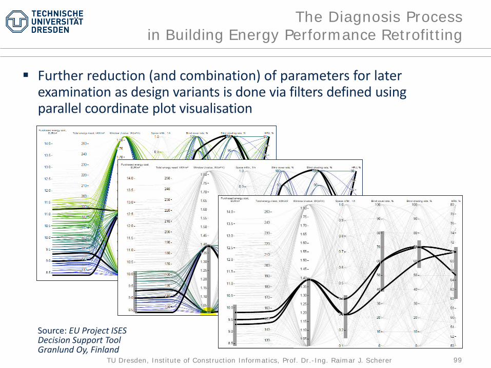
The Diagnosis Processin Building Energy Performance Retrofitting
Further reduction (and combination) of parameters for laterexamination as design variants is done via filters defined usingparallel coordinate plot visualisation
Source: EU Project ISESDecision Support ToolGranlund Oy, Finland

100TU Dresden, Institute of Construction Informatics, Prof. Dr.-Ing. Raimar J. Scherer
The Diagnosis Processin Bridge Retrofitting
Basically, the Diagnosis Process in Bridge Retrofitting follows the same steps as shown for building energy performance retrofitting above
However:− Potential weak points are determined through continuous monitoring
and/or querying a knowledge base of bridge structure types and relateddamage patterns and occurrence probability
− Sensitivity analysis is carried out in similar manner as for system identi-fication but taking into account damage development over time
Some possible damage areasbox girder bridge
101TU Dresden, Institute of Construction Informatics, Prof. Dr.-Ing. Raimar J. Scherer
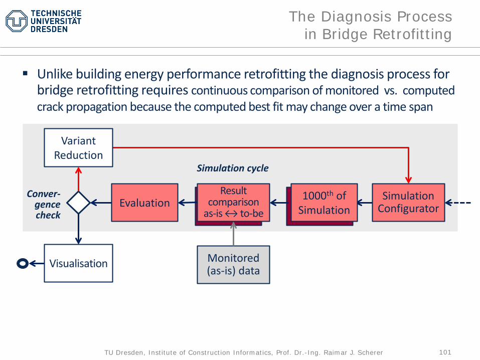
The Diagnosis Processin Bridge Retrofitting
Unlike building energy performance retrofitting the diagnosis process forbridge retrofitting requires continuous comparison of monitored vs. computed crack propagation because the computed best fit may change over a time span
SimulationConfigurator
Visualisation
Evaluation
Monitored(as-is) data
VariantReduction
Result comparison
as-is ↔ to-be
Simulation cycle
Conver-gencecheck
1000th ofSimulation
102TU Dresden, Institute of Construction Informatics, Prof. Dr.-Ing. Raimar J. Scherer
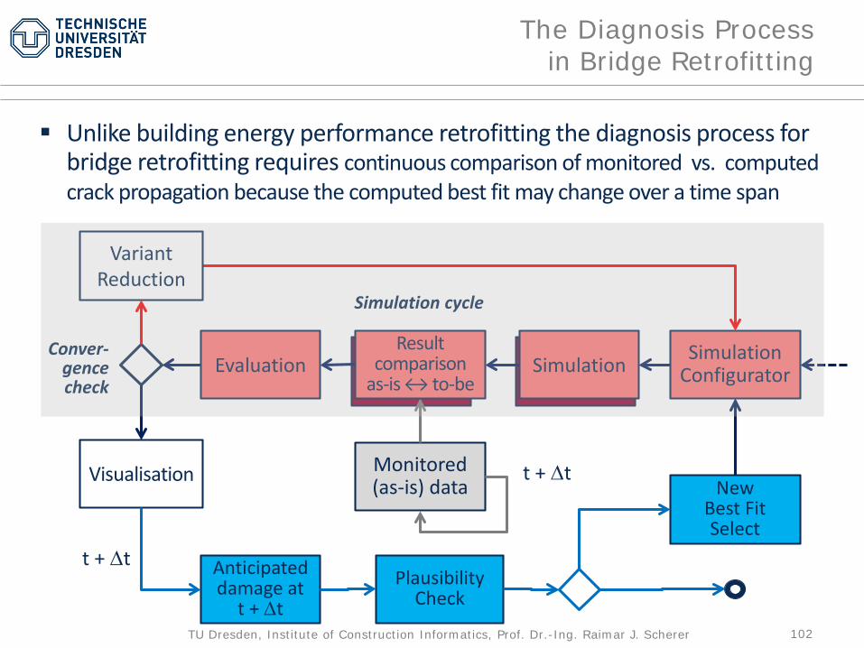
The Diagnosis Processin Bridge Retrofitting
Unlike building energy performance retrofitting the diagnosis process forbridge retrofitting requires continuous comparison of monitored vs. computed crack propagation because the computed best fit may change over a time span
SimulationConfigurator
Visualisation
SimulationEvaluation
Monitored(as-is) data
VariantReduction
Result comparison
as-is ↔ to-be
Simulation cycle
Conver-gencecheck
Anticipateddamage at
t + ∆tPlausibility
Check
New Best FitSelect
t + ∆t
t + ∆t

103TU Dresden, Institute of Construction Informatics, Prof. Dr.-Ing. Raimar J. Scherer
Therapy
104TU Dresden, Institute of Construction Informatics, Prof. Dr.-Ing. Raimar J. Scherer
The Therapy Process
Once created, BIM can be used in theTherapy Process in much the sameway as in the design of new facilities
The difference is that, because the model has not been created directly in CAD, use of knowledge templates for exploration of design variants may be more necessary,especially in the early design phase

105TU Dresden, Institute of Construction Informatics, Prof. Dr.-Ing. Raimar J. Scherer
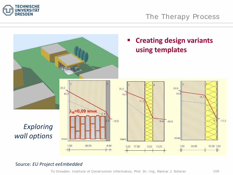
The Therapy Process
Creating design variants using templates
Source: EU Project eeEmbedded
106TU Dresden, Institute of Construction Informatics, Prof. Dr.-Ing. Raimar J. Scherer
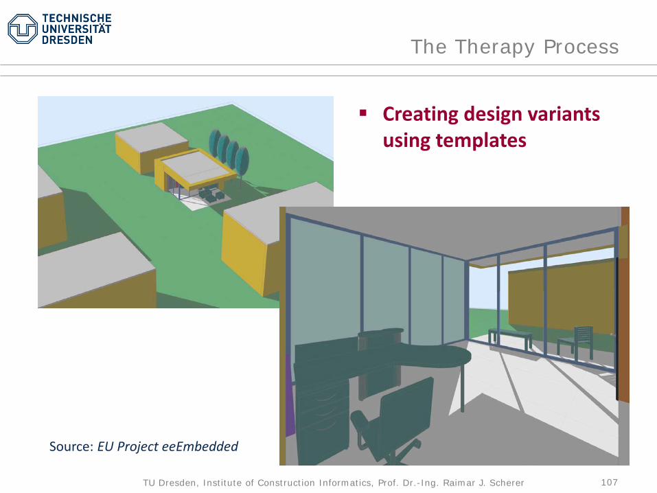
The Therapy Process
Creating design variants using templates
λR=0,09 W/mK
Exploringwall options
Source: EU Project eeEmbedded
107TU Dresden, Institute of Construction Informatics, Prof. Dr.-Ing. Raimar J. Scherer
The Therapy Process
Creating design variants using templates
Source: EU Project eeEmbedded

108TU Dresden, Institute of Construction Informatics, Prof. Dr.-Ing. Raimar J. Scherer
The Therapy Process
Creating design variants using templates
Source: EU Project eeEmbedded
109TU Dresden, Institute of Construction Informatics, Prof. Dr.-Ing. Raimar J. Scherer
Functional ICT Concept
110TU Dresden, Institute of Construction Informatics, Prof. Dr.-Ing. Raimar J. Scherer
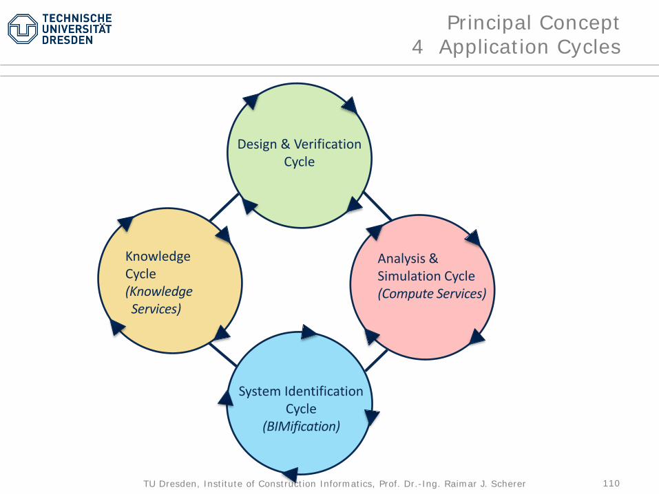
Principal Concept4 Application Cycles
Design & Verification Cycle
Knowledge Cycle(KnowledgeServices)
Analysis & Simulation Cycle(Compute Services)
System Identification Cycle
(BIMification)

111TU Dresden, Institute of Construction Informatics, Prof. Dr.-Ing. Raimar J. Scherer
System & ModelManagementCycleBIM Services
Principal Concept1 supporting Kernel Cycle = BIM Services
Design & Verification Cycle
Knowledge Cycle(KnowledgeServices)
Analysis & Simulation Cycle(Compute Services)
System Identification Cycle
(BIMification)
112TU Dresden, Institute of Construction Informatics, Prof. Dr.-Ing. Raimar J. Scherer13.09.2017
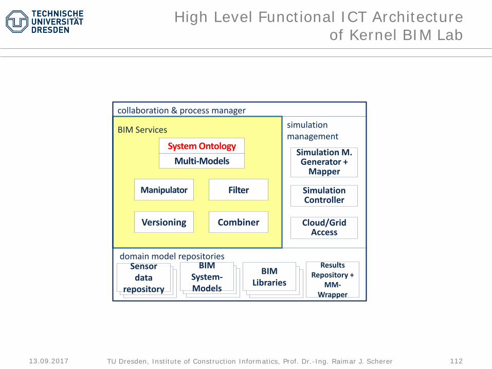
High Level Functional ICT Architectureof Kernel BIM Lab
domain model repositories
simulation management
collaboration & process manager
Combiner
Filter
Versioning
Manipulator
BIMLibraries
Multi-ModelsSystem Ontology
BIMSystem-Models
Sensor data
repository
Simulation M. Generator +
Mapper
Simulation Controller
Cloud/GridAccess
ResultsRepository +
MM-Wrapper
BIM Services

113TU Dresden, Institute of Construction Informatics, Prof. Dr.-Ing. Raimar J. Scherer
High Level Functional ICT Architecture
Domain model repositoriesBIM, ESIM, BEM etc.
Simulation managementservices
NumericalComputation
Tools:- Thermal - Moisture- Fluid dyn.- Structural- LCA- LCC
BIM Navigationand Steering
BIM Services
BIM - I/O
BIM Kernel Platform
Model Management
Cycle
NumericalComponent
BIM-CAD Modelling
NumericalCycle
Design Cycle
Collaboration & process management services
CAD-based Virtual Design Lab
114TU Dresden, Institute of Construction Informatics, Prof. Dr.-Ing. Raimar J. Scherer
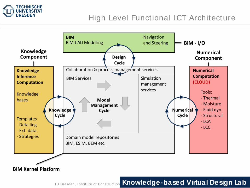
High Level Functional ICT Architecture
Domain model repositoriesBIM, ESIM, BEM etc.
Simulation managementservices
NumericalComputation(CLOUD)
Tools:- Thermal - Moisture- Fluid dyn.- Structural- LCA- LCC
BIM Navigationand Steering
KnowledgeInferenceComputation
Knowledge bases
Templates- Detailing- Ext. data- Strategies
BIM Services
BIM - I/O
BIM Kernel Platform
KnowledgeComponent
Model Management
Cycle
NumericalComponent
BIM-CAD Modelling
NumericalCycle
Design Cycle
KnowledgeCycle
Collaboration & process management services
Knowledge-based Virtual Design Lab

115TU Dresden, Institute of Construction Informatics, Prof. Dr.-Ing. Raimar J. Scherer
High Level Functional ICT Architecture BIM Lab
Domain model repositoriesBIM, ESIM, BEM etc.
Simulation managementservices
NumericalComputation(CLOUD)
Tools:- Thermal - Moisture- Fluid dyn.- Structural- LCA- LCC
BIM Navigation,Inspectionand Steering
KnowledgeInferenceComputation
Knowledge bases
Templates- Detailing- Ext. data- Strategies- Old Constr.
BIM Services
BIM - I/O
BIM Kernel Platform
KnowledgeComponent
Model Management
Cycle
Anamnesis DiagnosisBIMification
NumericalComponent
TherapyBIM-CAD Modelling
BIMificationCycle
NumericalCycle
Design Cycle
KnowledgeCycle
Collaboration & process management services
BIMification Lab

116TU Dresden, Institute of Construction Informatics, Prof. Dr.-Ing. Raimar J. Scherer
Virtual Lab Platform for ee-Design
Source: eeEmbedded project

117TU Dresden, Institute of Construction Informatics, Prof. Dr.-Ing. Raimar J. Scherer
Support behind
118TU Dresden, Institute of Construction Informatics, Prof. Dr.-Ing. Raimar J. Scherer
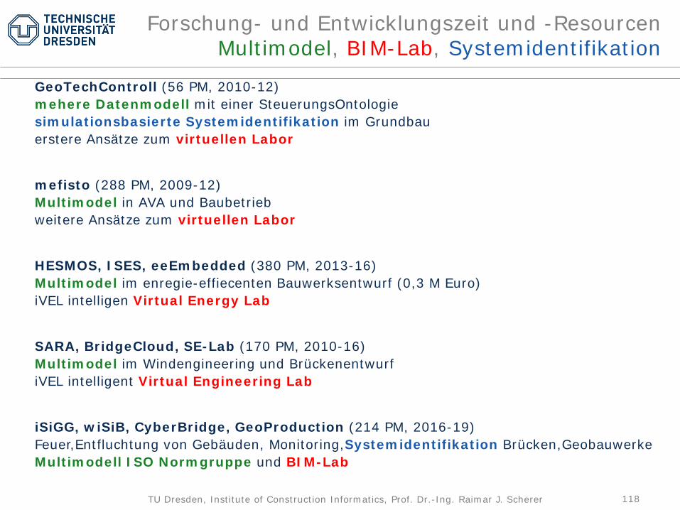
Forschung- und Entwicklungszeit und -ResourcenMultimodel, BIM-Lab, Systemidentifikation
GeoTechControll (56 PM, 2010-12)mehere Datenmodell mit einer SteuerungsOntologiesimulationsbasierte Systemidentifikation im Grundbauerstere Ansätze zum virtuellen Labor
mefisto (288 PM, 2009-12)Multimodel in AVA und Baubetriebweitere Ansätze zum virtuellen Labor
HESMOS, ISES, eeEmbedded (380 PM, 2013-16)Multimodel im enregie-effiecenten Bauwerksentwurf (0,3 M Euro)iVEL intelligen Virtual Energy Lab
SARA, BridgeCloud, SE-Lab (170 PM, 2010-16)Multimodel im Windengineering und BrückenentwurfiVEL intelligent Virtual Engineering Lab
iSiGG, wiSiB, CyberBridge, GeoProduction (214 PM, 2016-19)Feuer,Entfluchtung von Gebäuden, Monitoring,Systemidentifikation Brücken,GeobauwerkeMultimodell ISO Normgruppe und BIM-Lab
119TU Dresden, Institute of Construction Informatics, Prof. Dr.-Ing. Raimar J. Scherer
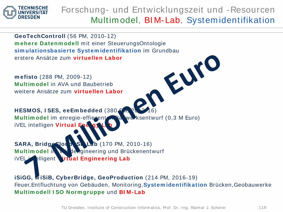
Forschung- und Entwicklungszeit und -ResourcenMultimodel, BIM-Lab, Systemidentifikation
GeoTechControll (56 PM, 2010-12)mehere Datenmodell mit einer SteuerungsOntologiesimulationsbasierte Systemidentifikation im Grundbauerstere Ansätze zum virtuellen Labor
mefisto (288 PM, 2009-12)Multimodel in AVA und Baubetriebweitere Ansätze zum virtuellen Labor
HESMOS, ISES, eeEmbedded (380 PM, 2013-16)Multimodel im enregie-effiecenten Bauwerksentwurf (0,3 M Euro)iVEL intelligen Virtual Energy Lab
SARA, BridgeCloud, SE-Lab (170 PM, 2010-16)Multimodel im Windengineering und BrückenentwurfiVEL intelligent Virtual Engineering Lab
iSiGG, wiSiB, CyberBridge, GeoProduction (214 PM, 2016-19)Feuer,Entfluchtung von Gebäuden, Monitoring,Systemidentifikation Brücken,GeobauwerkeMultimodell ISO Normgruppe und BIM-Lab