binary instruction format specification for nogap788082/fulltext01.pdf · binary instruction...
TRANSCRIPT

Institutionen för systemteknikDepartment of Electrical Engineering
Examensarbete
Binary Instruction Format Specification for NoGap
Examensarbete utfört i Datorteknikvid Tekniska högskolan vid Linköpings universitet
av
Yaochuan Chen
LiTH-ISY-EX--12/4609--SE
Linköping 2012
Department of Electrical Engineering Linköpings tekniska högskolaLinköpings universitet Linköpings universitetSE-581 83 Linköping, Sweden 581 83 Linköping


Binary Instruction Format Specification for NoGap
Examensarbete utfört i Datorteknik
vid Tekniska högskolan i Linköpingav
Yaochuan Chen
LiTH-ISY-EX--12/4609--SE
Handledare: Per Karlström
isy, Linköpings universitet
Examinator: Andreas Ehliar
isy, Linköpings universitet
Linköping, 29 June, 2012


Avdelning, Institution
Division, Department
Division of Computer EngineeringDepartment of Electrical EngineeringLinköpings universitetSE-581 83 Linköping, Sweden
Datum
Date
2012-006-29
Språk
Language
� Svenska/Swedish
� Engelska/English
�
⊠
Rapporttyp
Report category
� Licentiatavhandling
� Examensarbete
� C-uppsats
� D-uppsats
� Övrig rapport
�
⊠
URL för elektronisk version
http://www.da.isy.liu.se
ISBN
—
ISRN
LiTH-ISY-EX--12/4609--SE
Serietitel och serienummer
Title of series, numberingISSN
—
Titel
Title Binary Instruction Format Specification for NoGap
Författare
AuthorYaochuan Chen
Sammanfattning
Abstract
Nowadays, hardware designers want to get a powerful and friendly tool to speedup the design flow and design quality. The new development suit NoGap is pro-posed to meet those requirements. NoGap is a design automation tool for ASIP,it helps users to focus on the design stage, free them from module connection andsignal assignment, or integration. Different from the normal ADL tools which limitusers’ design ideas to some template frameworks, NoGap allow designers to im-plement what they want with NoGap Common Language (NoGapCL). However,NoGap is still not perfect, some important functionalities are lacking, but withthe flexible generator component structure, NoGap and NoGapCL can easily beextended.
This thesis will firstly investigate the structure of Novel Generator of Acceler-ators and Processors (NoGap) from software prospective view, and then present anew NoGap generator, OpCode Assignment Generator (OpAssignGen), which al-lows users to assign operation code values, exclude operation codes and customizethe operation code size or instruction size.
A simple example based on the Microprocessor without Interlocked PipelineStages (MIPS) instructions sets will be mentioned to give users a brief view ofhow to use OpAssignGen. After that, the implementation of the new generatorwill be explained in detail.
What’s more, some of NoGap’s flaws will be exposed, but more suggestionsand improvements for NoGap will be given.
At last, a successful synthesis result based on the simple MIPS hardware im-plementation will be shown to prove the new generator is well implemented. Moreresults and the final conclusion will be given at the end of the thesis.
Nyckelord
Keywords ASIP, NoGap, Parser, generator


Abstract
Nowadays, hardware designers want to get a powerful and friendly toolto speed up the design flow and design quality. The new development suitNoGap is proposed to meet those requirements. NoGap is a design au-tomation tool for ASIP, it helps users to focus on the design stage, freethem from module connection and signal assignment, or integration. Dif-ferent from the normal ADL tools which limit users’ design ideas to sometemplate frameworks, NoGap allow designers to implement what they wantwith NoGapCL. However, NoGap is still not perfect, some important func-tionalities are lacking, but with the flexible generator component structure,NoGap and NoGapCL can easily be extended.
This thesis will firstly investigate the structure of NoGap from softwareprospective view, and then present a new NoGap generator, OpAssignGen,which allows users to assign operation code values, exclude operation codesand customize the operation code size or instruction size.
A simple example based on the MIPS instructions sets will be mentionedto give users a brief view of how to use OpAssignGen. After that, theimplementation of the new generator will be explained in detail.
What’s more, some of NoGap’s flaws will be exposed, but more sugges-tions and improvements for NoGap will be given.
At last, a successful synthesis result based on the simple MIPS hard-ware implementation will be shown to prove the new generator is well im-plemented. More results and the final conclusion will be given at the endof the thesis.
v


Acknowledgments
Finally, I finished my thesis work. The completion of my thesis projectis really a good lesson for me. Although the work is tough, I definitelyget lots of experience about hardware design, programming and academicwriting.
Firstly I would like to give my gratitude to my supervisor Per Karlströmand examiner Andreas Ehliar. During my thesis project, I got lots of helpsfrom them. Without their helps, I cannot complete my project successfully.They give me lots of suggestions and advises which help me to improve mythesis significantly.
I deeply appreciate that Linköping University gave me a good studyenvironment. The appreciation also goes to my family, my girlfriend andall of my friends. Thank you for your supports.
vii


Contents
1 Introduction 3
1.1 Background . . . . . . . . . . . . . . . . . . . . . . . . . . . 3
1.2 Operation Code Generator . . . . . . . . . . . . . . . . . . . 4
1.3 Thesis and Chapter Overview . . . . . . . . . . . . . . . . . 4
2 Related Work 7
2.1 OpCode assignments in Other Architecture Description Lan-guage (ADL)s . . . . . . . . . . . . . . . . . . . . . . . . . . 7
2.1.1 Instruction Definition in LISA . . . . . . . . . . . . 7
2.1.2 Instruction Definition in ArchC . . . . . . . . . . . . 8
3 NoGap Architecture 11
3.1 NoGap System Overview . . . . . . . . . . . . . . . . . . . 11
3.2 NoGap Scanner . . . . . . . . . . . . . . . . . . . . . . . . . 14
3.3 NoGap Parser . . . . . . . . . . . . . . . . . . . . . . . . . . 14
3.4 Construcion of Abstract Syntax Tree (AST) in NoGap . . . 17
3.5 Symbol Talbe in NoGap . . . . . . . . . . . . . . . . . . . . 19
3.6 Parser Units . . . . . . . . . . . . . . . . . . . . . . . . . . . 19
3.7 Generator and Generator Registration . . . . . . . . . . . . 19
3.8 Flow Control and Error Handling . . . . . . . . . . . . . . . 23
4 Operation Code Assignment Introduction 27
4.1 Operation Code and Instruction Format in NoGap . . . . . 27
4.1.1 Character OpCode . . . . . . . . . . . . . . . . . . . 28
4.1.2 Instruction Format . . . . . . . . . . . . . . . . . . . 28
4.2 Purpose of Operation Code Assignment . . . . . . . . . . . 29
4.3 A Tutorial for OpCode Assignment . . . . . . . . . . . . . . 29
4.3.1 Define the Instruction and OpCode Size . . . . . . . 32
4.3.2 How to assign OpCode . . . . . . . . . . . . . . . . . 32
4.3.3 Auto-completion and Range Assignment . . . . . . . 32
ix

x Contents
4.3.4 OpCode Exclusion . . . . . . . . . . . . . . . . . . . . 344.4 OpAssignGen Configuration . . . . . . . . . . . . . . . . . . 36
5 OpCode Assignment Syntax 37
5.1 Introduction . . . . . . . . . . . . . . . . . . . . . . . . . . . 375.2 Design of Assignment Grammars . . . . . . . . . . . . . . . 375.3 Grammar for Assigning OpCode . . . . . . . . . . . . . . . . 38
5.3.1 Opcode Block . . . . . . . . . . . . . . . . . . . . . . 385.3.2 Operation Code Definition . . . . . . . . . . . . . . . 395.3.3 Grammar for define OpCode and instruction size . . 40
6 OpCode Assignment Generator 41
6.1 Procedures of OpCode assignment . . . . . . . . . . . . . . . 416.2 Scanner and Parser Extension for OpAssignGen . . . . . . . 426.3 Representation of OpCode . . . . . . . . . . . . . . . . . . . 436.4 Data Structure in OpAssignGen . . . . . . . . . . . . . . . 446.5 OpAssignGen Process Flow . . . . . . . . . . . . . . . . . . 466.6 Structure of AssignOpHandler . . . . . . . . . . . . . . . . 49
6.6.1 Processing Flow for AssignOpCodeHandler . . . . . 506.7 Instruction and OpCode Size Definition . . . . . . . . . . . . 546.8 OpAssignGen Registration . . . . . . . . . . . . . . . . . . . 54
7 NoGap Improvements and suggestions 57
7.1 NoGap Error Detection and Handling . . . . . . . . . . . . 577.2 Better Application Programmer Interface (API) and Inter-
face for NoGap . . . . . . . . . . . . . . . . . . . . . . . . . 58
8 Results 61
8.1 Results of Synthesizing . . . . . . . . . . . . . . . . . . . . . 62
9 Conclusions 63
10 Future Work 65
A Implementaion for Part of MIPS Instructions 67
B OpCode Assignment Definiton for the Parser 73
C The Implementation of OpAssignGen 75
Bibliography 77

List of Figures
3.1 NoGapCL Flow from Dr Karlström’s thesis [4] . . . . . . . . 123.2 NoGap system architecture from Dr Karlström’s thesis [4] . 133.3 Small binary trees generated with the functions in Listing 3.3 173.4 Graph vertexs (Vs) inheritance diagram . . . . . . . . . . . 183.5 Symbol table architecture . . . . . . . . . . . . . . . . . . . 193.6 Generator Flowchart . . . . . . . . . . . . . . . . . . . . . . 22
4.1 Instruction format example from Dr Karlström’s thesis [4] . 29
6.1 OpCode representation UML . . . . . . . . . . . . . . . . . 456.2 OpCode Assignment Flowchart . . . . . . . . . . . . . . . . . 486.3 AssignOpHandler and AssignOpCodes Unified Modeling Lan-
guage (UML) . . . . . . . . . . . . . . . . . . . . . . . . . . 496.4 A Simple AST generated from the Assignment in Listing 6.5 52

Contents 1
List of Tables
4.1 Instructions’ OpCodes in MIPS Architecture . . . . . . . . . 284.2 All possible OpCodes generated by the incomplete OpCode
definition . . . . . . . . . . . . . . . . . . . . . . . . . . . . 33
6.1 Vertex type . . . . . . . . . . . . . . . . . . . . . . . . . . . 44
8.1 Synthesizing Results . . . . . . . . . . . . . . . . . . . . . . 62


Chapter 1
Introduction
1.1 Background
There is a dream of designing hardware quickly and implementing designseasily just like software development. In the past several years, some de-velopment tools and hardware languages have tried to realize this dream.However, those tools have problems to balance the different requirements:rich/powerful design possibilities and a simple design procedure. The clas-sic examples are some ADL tools. Predefined templates are used to simplifythe design flow, which give designers an abstract HW view and free themfrom connection details. However, the price of such convenience is highsometimes. Designers cannot touch the architecture detail and their cre-ativity are restricted by templates. This limitation is not good for novelHW designs.
On the other hand, Hardware Description Language (HDL)s such asVerilog allow designers completely control what they want. Then designershave a relative open space to turn their ideas to reality, but sometimes itis not convenient and efficient either, especially for the instruction drivenarchitectures. Designers have to take care all details, assign every controlsignal bit, check every instruction and merge them into the architecture .What’s more, HDLs are really not friendly for the beginner or people whohaven’t so much hardware knowledge.
The new hardware design tool NoGap is proposed to solve above prob-lem. NoGap tries to give designers possibilities to manage micro architec-ture details and convenient templates to simplify the design procedure atthe same time.
Like the Transaction-level modeling [5], NoGap separates the details ofcommunication from the details of functional implementation. All function
3
4 Introduction
units in the system contains two different part, Micro Architecture Gener-ation Essentials (Mage) which describes the component functionality, andanother part Micro Architecture Structure Expression (Mase) describingthe connection details between the function units.
From the software view, NoGap is similar to a compiler, which con-tains three levels: front-end, intermediate representation and back-end. InNoGap, the back-end is made up of generators and spawner’s. This back-end interface is fairly flexible. NoGap’s functionality can be extended easilyby adding new generators.
1.2 Operation Code Generator
In this thesis, I will mainly focus on the back-end and introduce, the OpCode
Assignment Generator, a new NoGap generator which allows designers tocustomize operation code value, exclude unused operation units and defineinstruction or opcode length.
After the operation code customization, the processor modeled by NoGap
may recognize and execute multiple instruction sets. In other words, theexecutable binary file compiled in other instruction sets can be executed bythat processor. This new generator improves designs’ customization abilityand extends the compatibility at the same time.
However, during the design of OpCode assignment generator, we have toface these questions: how to extend NoGapCL, how to design and simplifyoperation code assignment, what new features we should achieve for thesecustomization, and what the structure of new generator we should use fromsoftware view. Next chapters in this these will show our implementation indetail and explain reason inside.
1.3 Thesis and Chapter Overview
This thesis will explain the architecture of NoGap from a programmer’s per-spective, introduce the new OpCode Assignment Generator, and illustratehow to use the new functionality with some use cases.
The goals I want to achieve in this thesis are listed below:
1. Explain the architecture of NoGap
2. Illustrate how to assign OpCode by some examples
3. Introduce the OpAssignGen
4. Explain the implementation of the new generator in detail

1.3 Thesis and Chapter Overview 5
5. Give some possible software improvement suggestions for NoGap
6. Show system synthesis results
The following list shows every chapter’s content in brief:
• Chapter 1 gives introduction about the thesis.
• Chapter 2 shows the comparison among different hardware designtools.
• Chapter 3 explains the NoGap architecture from a software perspec-tive
• Chapter 4 introduces the OpCode assignment and shows some ex-amples.
• Chapter 5 describes the implementation of OpCode Assignment Gen-erator in detail
• Chapter 6 offers improvement suggestions aboutNoGap.
• Chapter 7 gives a result about the synthesist hardware report.
• Chapter 8 makes a conclusion of the OpCode Assignment Generator
• Chapter 9 shows the future work.


Chapter 2
Related Work
When we design new processors, a good instruction sets is very importantIn this chapter, I will discuss issues about instruction size and OpCode
size. After that, OpCode assignments in other ADL will be shown as acomparison.
2.1 OpCode assignments in Other ADLs
Currently, there are lots of ADLs developed to simplify the hardware de-sign. The ADLs can help designers to generate multiple outputs includingcompiler, simulator, assembler and debugger. All these outputs are basedon the abstract hardware description. These ADLs require designers tospecify the architecture of processor, memory and the connection of com-ponents [7]. I will not compare these ADLs with NoGap here, becausesuch comparisons have been shown in Dr Karlström’s thesis [4]. Becauseof the importance of instruction description for hardware design, I want tofirstly talk about the instruction definition in other ADLs. The followingexamples will show how to define OpCode in LISA [10] and ArchC [11].
2.1.1 Instruction Definition in LISA
Lisa is an ADL mixing with the features of structural and behavioral ADLs.This means Lisa may touch the lower to RTL abstraction level and hidethe gate-implementation, but it is also possible to abstract behavioral in-formation to simplify the instruction sets extraction [6].
The operation definition in LISA uses an operation tree to show therelation among different operation declarations. Different with NoGap,LISA focuses on an Instruction Set Architecture (ISA) which captures all
7

8 Related Work
of information of instructions such as syntax, behavior and encoding [6].Then, designers can add or map structural descriptions based on theseinstruction description. Listing 2.1 shows how to define the ADDI instructionin LISA. We may notice the operation code value and instruction formatare defined in CODING block. Furthermore, with the keywords SYNTAX andBEJAVIOR the instruction name and behavior are also defined at the sametime.
There is no doubt that the LISA’s instruction definition grammar ismore powerful than NoGap’s. Currently, we can not set instruction formatin NoGap. Operation code definition grammar can only assign the numer-ical value to operation code, and instruction names and behaviour have tobe assigned in different place. Actually, NoGap has a different view withLISA, which describes and abstracts hardware through their functions andoperations. In other words, designers define instruction sets after hardwarestructures and functionalities have been defined.
So, the instruction definition is not the most important part in NoGap.On the contrary, all structural or further descriptions in LISA are based onISA. The instruction definition grammar must be powerful to make sureinstruction sets can be described in detail.
Listing 2.1. Instruction Definition in LISA from the paper [9]
1 /*
2 * The o p e r a t i o n ADDI is defined
3 * Its instruction format is clearly shown in list.
4 * The p i p e l i n e or the execution phase has shown.
5 * Its OpCode is 01100 in binary format.
6 */
7 OPERATION ADDI IN pipe.DC {
8 DECLARE {
9 GROUP rs1 , rd = fix_register;
10 LABEL immediate;
11 }
12 CODING { 0b001000 rs1 rd immediate =0bx[16] }
13 SYNTAX { "ADDI" rd "," rs1 "," immediate =%d }
14 BEHAVIOR { rd = rs1 + immediate; }
15 }
2.1.2 Instruction Definition in ArchC
ArchC is an open-source ADL based on SystemC. It can be used to describea large range of processors. Mostly ArchC is used to verify and explorea new architecture instead of the real hardware implementation. ArchC

2.1 OpCode assignments in Other ADLs 9
can also automatically generated tools such as simulator, compiler andassembler to help designers experiment and evaluate new ISAs [1].
The final outputs of ArchC is SytemC programs. We can find thatthe syntax style of ArchC are heavily borrowed from C++/SystemC. Thisinputs relies both structural and instruction-level information [7]. Nor-mally, the ArchC inputs are composed with two parts: Architecture Re-sources starting with AC_ARCH and Instruction Set Architecture startingwith AC_ISA.
Listing 2.2 shows how to define the instruction format and declare in-struction in ArchC. In the block AC_ISA, all information are provided toconstruct a decoder. We can find that from line 2 to 3, two different in-struction formats are defined. After that, two instructions, add and load,are declared. On line 11, the add instruction’s operation code value is as-signed. The notable thing is designers may define multiple OpCode fieldsand assign them easily. The grammar and functionality for instruction def-inition is powerful also and well designed. Although instruction size andoperation code can be customized with new generator, the adjuration ofinstruction format is still not flexible in NoGap. Compared with ArchC,the operation code definition in NoGap is more clear and simple to use, butit is necessary to improve current grammar and add more functionalities,and ArchC is a good reference for the improvement of NoGap.
Listing 2.2. Instruction Definition in ArchC from the manual [1]
1 AC_ISA(mips){
2 ac_format Type_R = "%op1:6␣%rs:5␣%rt:5␣%rd:5␣0x00:5␣%op2:6";
3 ac_format Type_I = "%op1:6␣%rs:5␣%rt:5␣%imm :16";
4
5 \\ Declare the instruction
6 ac_instr <Type_R > add;
7 ac_inst <Type_I > load;
8
9 ISA_CTOR(mips) {
10 add.set_asm("add␣%reg ,␣%reg ,␣%reg", rd , rs , rt);
11 add.set_decoder(op1=0x00 , op2=0x20);
12 load.set_asm("lw␣%reg ,␣%imm(%reg)", rt , imm , rs);
13 load.set_decoder(op1=0x23);
14 }
15 }


Chapter 3
NoGap Architecture
Because the implementation of the operation code generator (OpAssignGen),need to touch NoGap deeply, it is better to firstly understand what NoGap
is and how NoGap works. In this Chapter, NoGap’s architecture will beexplained in brief. I will mainly focus on the parser, symbol table, AST,parser unit, generator, control flow and error handling in NoGap.
3.1 NoGap System Overview
NoGap is ADL tool for hardware designers. “The underlying design princi-ple in NoGap is based on the assumption that designing individual modules,e.g. adders, multipliers, or Arithmetic Logic Unit (ALU)s of a pipelinedarchitecture is generally a fairly simple task for a human, even for relativelyinexperienced designer.” – – from Dr Karlström’s thesis [4]
NoGap simplifies designers’ work, improves the design quality and gen-erates multiple outputs, such as assemblers, simulators, and synthesizableRegister Transfer Language (RTL) code. The working flow of NoGap isshown in Figure 3.1. [4]
The idea behind NoGap is to let computer finish the repeated and com-plex works such as instructions merging for a pipelined Application SpecificInstruction-set Processor (ASIP) architecture, assigning control signals andmanaging delays. Designers just need to finish simple or creative workslike instructions definition, specific the modules and the relations betweenthese modules. This strategy helps designers focus on innovation and nov-elty. To realize such idea, NoGap use a input which has the descriptionsof hardware functionality, detailed data path structure and definitions ofinstruction sets.
The architecture of NoGap is split into three parts. They are facets,
11

12 NoGap Architecture
Figure 3.1. NoGapCL Flow from Dr Karlström’s thesis [4]
NoGap-core, and spawners. Figure 3.2 shows an overview of NoGap. Fromthis figure, we may notice that NoGap is really like a compiler. A normalcompiler is composed by three parts: front-end, intermediate representa-tion and back-end. Then, the parser in the facet corresponds to the frontend which scans, parses the input, and generates the intermediate repre-sentation. The input files for NoGap are normally some HW descriptionswritten in NoGapCL. NoGapCL is used to describe the construction inNoGap. The usage of the language is not important in my thesis, andthe detail introduction about NoGapCL can be found in [4]. NoGap Com-mon Description (NoGapCD) is the intermediate representation in NoGap,which contains a collection of Parse Units (PUs). In NoGap, a PU is rep-resented by the class ParseUnit. This class has not only the AST but alsosome other important members, such as the annotated data flow graphMase, information needed by instruction decoders construction or certaindata needed by various generators.
A spawner is arranged to complete a task. The idea of spawner is justa design concept. Normally, a spawner is made up of multiple generatorswhich will process the intermediate representation data and finally gen-erate some outputs, such as Verilog files, simulator or instruction table.Generators are components in NoGap and they are independent with eachother. They can be configured and registered separately in NoGap system,which means generators can be added or removed easily. In other words,the functionality in NoGap can be extended easily also.
There is no doubt NoGap is similar with compiler, but it is not just acompiler. In the following sections, I will dive into NoGap’s processing flowand explain why NoGap is different from a compiler. At the same time,the generator architecture, NoGap’s data structure and some important

3.1 NoGap System Overview 13
Figure 3.2. NoGap system architecture from Dr Karlström’s thesis [4]

14 NoGap Architecture
classes, functions in the source codes will be illustrated as well.
3.2 NoGap Scanner
Same with the normal compiler, NoGap front-end is composed by two parts:scanner and parser. First of all, NoGap will break down the input into alist of tokens. The NoGapCL grammar is borrowed from C++ and Verilogheavily, so the syntax elements in NoGapCL are similar with the languagesmentioned above, which includes identifiers, integer numbers, operatorsand so on. NoGap uses flex to generate the scanner. Flex [8], the fastlexical analyzer, is a tool for generating scanners, which uses pairs of regularexpressions and C/C++ code to describe lexical patterns. The NoGap
scanner descriptions are defined in one file. Listing 3.1 shows part of scannerdefinition. On line 2 to 5, they defines how the comment types are handled.From line 9, some return types, or in other words returned tokens aredefined for digital and certain NoGapCL keywords. When the scanner getssuch keywords from the inputs, the tokens will be returned and passed tothe parser for further processing.
Listing 3.1. Scanner Definition
1 //comment type d e f i n i t i o n s2 "/*" BEGIN(comment );
3 <comment >"\n" {ncdlloc.first_line ++;}
4 <comment >"*/" BEGIN(INITIAL );
5 <comment >. {}
6 //comment type d e f i n i t i o n s end7
8 // keyword d e f i n i t i o n s9 "fu" { r e t u r n TT_FU; }
10 "template" { r e t u r n TT_TEMPLATE; }
11 "main" { r e t u r n TT_MAIN; }
12 ...
3.3 NoGap Parser
The parser is most important part of the front-end in NoGap. In thischapter, I will explain how the parser is generated in detail and illustratethe generation of AST, because my new generator highly relays on theparser and AST. To implement the OpCode customization functionality,the scanner and parser in NoGap have to be extended, so some illustrations

3.3 NoGap Parser 15
such as how to define new rules in NoGap parser, and how to insert nodesor edges in the AST are necessary.
The parser in NoGap is generated by Bison [2], which is a LR parser.The definition is a BNF grammar which declares the makeup of some keyconcepts in NoGapCL such as statements, expressions and clauses. Bisonuses rules to express the grammar. Normally, a rule is composed by severalterminal or non terminal symbols. The terminal symbol in Bison is tokentype which stand for keywords in the language. In Bison, there are twotypes of terminal representation. One is identifier name and another is Cstring constant characters. The rule will follow a set of of actions whichare executed when the rule matches the input. All rules defined for thegrammar will execute and merge recursively. Normally, the parser willgenerate a tree in the end. In our case, we will get an abstract syntax treerepresented with boost graph [12].
Listing 3.2 defines if and else if statements. I will utilize some ex-amples to explain how nodes and edges are inserted into the AST. Line1 defines how to get the if_stmt node. When the parser gets a key wordif, the parser will try to match the remaining terminal or non terminalsymbols with the inputs. If they are matched, the following action will beexecuted. The function insertNode will be invoked to insert a node of typeIf into the AST. We might notice that there are some special variableslike $$ and $3 in the action. These variables represent the correspondingpositions in the rule. The $$ means the start symbol in the rule. In ourcase, the start symbol is if_stmt, and $1 stands for TT_IF where is thefirst place after the colon in the rule. $3 to $5 represent the correspondingsymbols on that places. $$ is given a value which is returned by functioninsertNode. I will explain that function and the AST in detail later. Theelseif_stmt is more complex than if_stmt, because the elseif_stmt hasmore possibilities. In NoGapCL, we may use multiple elseif blocks or justend with one else block. From line 12 to line 27 in Listing 3.2, all possibleelse_if statements are listed. Their actions are similar with the action inthe if statement.
The if_stmt and elseif_stmt are assigned to a value returned byfunction insertNode. The type returned by insertNode is a vertex de-scriptor. I will illustrate the descriptor later in NoGap AST. In the List-ing 3.3, two versions of insertNode function are defined. The first versionaccepts two nodes and edges as input arguments and finally generate asmall binary tree. Figure 3.3 shows two types of trees generated by thattwo version of insertNode functions. The second argument, EdgeOrder,is an index for edges. It is used to traverse the tree from one node to an-

16 NoGap Architecture
Listing 3.2. parser definition
1 // d e f i n e s a r u l e about how to handle the i f s tatement2 if_stmt: TT_IF ’(’ expr ’)’ statement
3 {
4 $$ = insertNode(parse_data.ast(),info::If(),
5 info:: EdgeOrder (),$3 ,$5 ,@$.first_line );
6 };
7
8 /∗9 ∗ d e f i n e s a l l p o s s i b l e e l s e i f s ta tements
10 ∗ and t h e i r corresponding a c t i o n s11 ∗/12 elseif_stmt: TT_ELSEIF ’(’ expr ’)’ statement
13 {
14 $$ = insertNode(parse_data.ast(),
15 info:: ElseIf(),
16 info:: EdgeOrder (),
17 $3 , $5 , @$.first_line );
18 }
19 | TT_ELSEIF ’(’ expr ’)’ statement elseif_stmt
20 {
21 $$ = insertNode ...
22
23 }
24 | TT_ELSE statement
25 {
26 $$ = insertNode ...
27 }
Listing 3.3. Function insertNode Definition
1 /∗2 ∗ t h i s func t io n generated a smal l b inary t r e e3 ∗ which the root node has two c h i l d nodes .4 ∗/5 vdesc_t parser ::ast:: insertNode(Graph &g, const info:: Statement &ninf ,
6 const info:: EdgeOrder &einf1 ,
7 const vdesc_t &child1 ,
8 const info:: EdgeOrder &einf2 ,
9 const vdesc_t &child2 ,
10 const uns igned i n t &line)
11
12 // t h i s func t io n g e t a s imple t r e e which has only two nodes at a l l .13 vdesc_t parser ::ast:: insertNode(Graph &g, const info:: Statement &ninf ,
14 const info:: EdgeOrder &einf ,
15 const vdesc_t &child ,
16 const uns igned i n t &line)

3.4 Construcion of AST in NoGap 17
Figure 3.3. Small binary trees generated with the functions in Listing 3.3
other one. The argument ninf in the function designate the current rootnode of the tree. In the case I mentioned above, the root node is the classparser::ast::info::If which inherits from the class Statement. Thatclass is the base class for all node types. The last function argument, line,means the line number of root node in the input file. We may use this linenumber later to tell users where the problem is when an error is caught.
3.4 Construcion of AST in NoGap
In NoGap, the AST normally represents as Mage. We use symbol Mage
Vertex (VMage) and Mage Edge (EMage) to stand for the node type andedge type in the Mage. The AST in NoGap is represented with boostadjacency graph. The types of edge and node in the AST are representedwith info::Edge and info::Statement.
However, as the base class of VMage, class info::Statement has manysub types. Figure 3.4 shows the major of Vs derived from the Statement.This figure is relative small, but it shows that most of statements andkeywords in NoGapCL have corresponding node type in the AST. Althoughthese nodes have different names, they are almost the same except someof the nodes have extra attributes such as the node name or number ofstatements.
What’s more, the class Statement inherits some methods from inter-face OutStreamable and PolyNewClonable. The interface OutStreamable
contains a print method. The object which implements this interface mayreturn a string representation of the object. The PolyNewClonable inter-face is used to clone an instance. There are multiple methods implementedin the class Statement. More detailed information about Statement canbe found in [4].

18 NoGap Architecture
Figure 3.4. Vs inheritance diagram

3.5 Symbol Talbe in NoGap 19
3.5 Symbol Talbe in NoGap
The symbol table representation in NoGap is the class parser::SymbolTable.The core element in this table is class parser::Symbol, which records theessential symbol attributes such as type, name, and values. All clausesin NoGapCL locate in the same level without hierarchical structure. Fig-ure 3.5 shows the architecture of symbol table with an UML diagram, thesymbol object is basic element in the symbol table. Most of statementsgotten by the parser will be represented with the type symbol and kept bythe symbol table.
Figure 3.5. Symbol table architecture
3.6 Parser Units
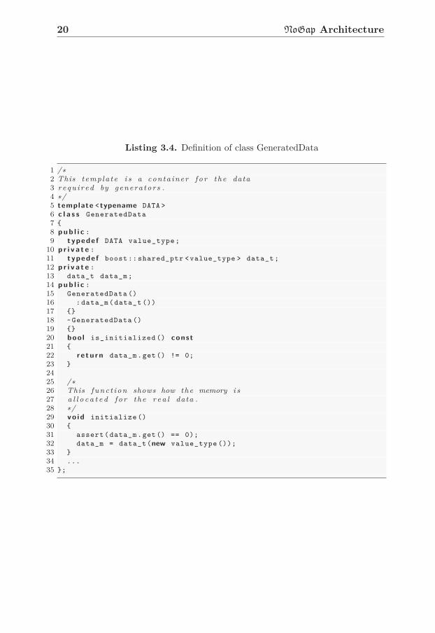
The PU is a core element in NoGap, for every Functional Unit (FU) inthe input file. It must exist a corresponding PU which contains all infor-mation for that FU. The PU is represented as class parser::ParseUnit.Notable members in the PU are AST graph ast_m, Mase graph, operationinfo, and the Mage dependency graph. Most of these members in the PUare wrapped by the container generator::GeneratedData<Data>. Thiscontainer will keep an uninitialized boost shared pointer which point tothe type DATA when the ParseUnit is generated. The memory used bythe DATA type will be allocated by a generator when it handles the PU.Some important methods in this container are shown in Listing 3.4. Themethod is_initialized is used to check whether the data is initialized.Normally, this method will be called by some generators to verify whetherthe pre-dependency data type is initialized. The initialize function, online 29, is used to allocate memory for the data and initialize the sharedpointer.
3.7 Generator and Generator Registration
A generator is a software component that processes PUs [4]. Generators areresponsible to perform most of tasks in NoGap, such as the symbol table
20 NoGap Architecture
Listing 3.4. Definition of class GeneratedData
1 /∗2 This templa te i s a conta iner f o r the data3 r equ i r ed by genera tors .4 ∗/5 template < typename DATA >
6 c l a s s GeneratedData
7 {
8 p u b l i c :
9 typede f DATA value_type;
10 p r i v a t e :
11 typede f boost :: shared_ptr <value_type > data_t;
12 p r i v a t e :
13 data_t data_m;
14 p u b l i c :
15 GeneratedData ()
16 :data_m(data_t ())
17 {}
18 ~GeneratedData ()
19 {}
20 boo l is_initialized () const
21 {
22 r e t u r n data_m.get() != 0;
23 }
24
25 /∗26 This func t io n shows how the memory i s27 a l l o c a t e d f o r the r e a l data .28 ∗/29 vo id initialize ()
30 {
31 assert(data_m.get() == 0);
32 data_m = data_t(new value_type ());
33 }
34 ...
35 };

3.7 Generator and Generator Registration 21
generation, syntax validation check, or even drawing abstract syntax trees.Generators may be independent with each other. They are initialized,released at the beginning of NoGap processing stage, implemented with thegenerator interface and managed under the generator registration strategy.Based on this strategy, we may easily add new generator to NoGap. Inthe next chapter, I will introduce a new generator that extends NoGap’sfunctionality.
Listing 3.5. Generator interface
1 c l a s s Generator
2 {
3 pro tec ted :
4 v i r t u a l const boo l
5 /∗6 ∗ The p r e d i c a t i o n func t io n i s used to7 ∗ v e r i f y the e x i s t e n c e o f dependencies8 ∗/9 generate_predicate ( const parser :: ParseUnit &) const ;
10 v i r t u a l vo id ope ra to r ()( parser :: ParseUnit& pu) = 0;
11 p u b l i c :
12 Generator ();
13 v i r t u a l ~Generator ();
14 boo l generate(parser :: ParseUnit& pu);
15 v i r t u a l vo id initialize ();
16 v i r t u a l vo id finalize ();
17 v i r t u a l vo id reset ();
18 };
All generators are derived from the base class generator::Generator.Listing 3.5 shows most methods in that base class. For every generator,they may override these methods to do their own tasks without takingcare how these methods are invoked. The method generate_predicate
on line 9 is used to check whether the generator should process this PU.A generator will normally override the method on line 10 to implementthe processing on the PUs. The method generate on line 14 will call thevirtual method operator() to process PUs, and the reset function willreset the generator when the process is finished. Different with the methodsmentioned above, the methods initialize and finalize will only run onetime when the generator is initialized and released respectively. These twofunctions may do some extra works for the generator, such as initialize orclear global variables.
The flowchart shown in Figure 3.6 displays a normal generator process-ing flow.
Besides the universal generator interface, all generator are registered

22 NoGap Architecture
Figure 3.6. Generator Flowchart

3.8 Flow Control and Error Handling 23
in NoGap. The generator registration helps NoGap to call generatorsfrom string. Listing 3.6 gives an simple example showing how the Ver-ilog generator is registered in NoGap. The string argument in the methodregister_generator is the generator name which will be used in the flowcontrol file to configure the generator processing flow. For more informationabout the generator usage, you may find them from [4].
Listing 3.6. Generator registration
1 vo id default_registration(Register& reg)
2 {
3 ...
4 reg.register_generator <generator ::Verilog >("gen_verilog");
5 ...
6 }
3.8 Flow Control and Error Handling
In NoGap, the configuration file is called flow control file or flow-configurationfile. This file controls the generator processing flow and set generators’ op-tions at the same time.
An XML based flow-configuration file is used to configure the generatorsin NoGap. Listing 3.7 shows what the eXtensible Markup Language (XML)configuration file looks like. We can use the generator element with type
attribute to specify what generator we want to run (line 4). A more specialcase on line 7 uses the extra attribute enabled to specify whether the gen-erator will be run. On line 10, we may use the element option to set someoptions in the generator, if that generator offers such options. The finish
element on line 12 will halt the execution flow. The generators after thefinish element will be ignored. For example, the generator gen_assemblerand gen_simulator on line 13 and 14 are excluded from the flow. Becauseof the limited space, the more detailed guidelines about the XML configu-ration file can be found in Dr Karlström’s paper. [3]
To handle errors in NoGap, some exceptions have been defined in NoGap
Listing 3.8 shows the usage of macro NOGAP_NORMAL_ERROR. This macro willinstantiate an exception error::Normal which contains an error message,file name and line number.
On the other hand, the class CompileIssueHandler is used to holdand handle issues. These issues will pass information to users directlyduring the NoGap compilation stage. The issue is represented as class

24 NoGap Architecture
Listing 3.7. XML flow file example
1 <?xml v e r s i o n ="1.0" ?>
2 <!DOCTYPE flow SYSTEM "flow_format.dtd">
3 <flow>
4 <generator type="gen_set_file_name " />
5 <generator type="dot_parsed_ast" />
6 <generator type="gen_symbol_table" />
7 <generator enabled="no" type="validate_identifiers" />
8 <generator enabled="no" type="validate_identifiers" />
9 <generator type="gen_op_classes">
10 <option >verbose </option >
11 </generator >
12 <finish />
13 <generator type="gen_assembler " />
14 <generator type="gen_simulator " />
15 </flow>
Listing 3.8. Exception in NoGap
1 ...
2 throw NOGAP_NORMAL_ERROR ("Vertex␣is␣neither␣input␣nor␣output␣port");
3 ...
nogap_system::Issue. There are three types of issue: error, warning andnote. The error issue will stop the NoGap compilation after the currentgenerator finishing its work.
The issue handler structure works like a stack, which issues are put andpop from the handler in order. The handler will reset itself when a gen-erator starts work. The issues raised by that generator during processingare kept by the handler. When the generator completes its work, the han-dler would check whether there is an issue. If issues are found, they willbe processed according the insertion order, which means the message andissue type will be printed one by one. If the handler found an error issue,it would call a method to stop the NoGap compilation. The definitionsof Issue and CompileIssueHandler are shown in Listing 3.9. The classCompileIssueHandler is a special type. For the hole NoGap global space,only one issue handler instance would be instantiated. Although techni-cally not correct, the CompileIssueHandler can be thought of a staticclass. Line 13 shows this issue handler is also non-copyable. To get thehandler in a generator, we can use the static method get() on line 31 toget the handler pointer. The get() method allocates memory for issuehandler if the static shared pointer defined on line 29 is not initialized, and

3.8 Flow Control and Error Handling 25
then returns the shared pointer directly.
Listing 3.9. Definition of Issue and Handler
1 // D e f i n i t i o n o f I s sue2 s t r u c t Issue
3 {
4 s t r u c t severity_t { enum enum_t {INFO=2, WARNING =1, ERROR =0}; };
5 const std:: string file_m;
6 const uns igned i n t line_m;
7 const severity_t :: enum_t severity_m; // the l e v e l o f I s sue8 Issue( const std:: string& file , const uns igned i n t & line ,
9 const severity_t :: enum_t& severity );
10
11 };
12
13 c l a s s CompileIssueHandler : p r i v a t e boost :: noncopyable ,
14 p u b l i c policy :: OutStreamable
15 {
16 p r i v a t e :
17 // the conta iner f o r h o l d ing a l l I s s u e s18 typede f std::multimap <Issue ,
19 boost :: shared_ptr <std:: stringstream > > issues_t;
20 ...
21 p r i v a t e :
22 issues_t issues_m;
23 boost ::optional <issues_t ::iterator > curr_issue_m;
24
25 /∗26 ∗ The s t a t i c l i n k i s used to make sure t h a t27 ∗ t h er e i s only one issue_hanler ins tance in NoGAP.28 ∗/29 s t a t i c boost :: shared_ptr <CompileIssueHandler > compile_issue_handler_m ;
30 p u b l i c :
31 s t a t i c CompileIssueHandler & get();
32
33 ...
34 };


Chapter 4
Operation Code Assignment
Introduction
In this chapter, I will explain the OpCode and introduce the purpose of oper-ation code assignment. Then an implementation which is partly compatiblewith MIPS instructions will be shown to illustrate OpCode assignment.
4.1 Operation Code and Instruction Format in
NoGap
The operation code, which is known as OpCode, is a part of instructionwhich specifies the operations to be executed. The operation code containsmultiple bits, and the OpCode value is normally represented as a binarynumber. Figure 4.1 displays the position of operation code in MIPS, andTable 4.1 shows certain I-type MIPS instructions and their OpCode values.The I-type instruction in MIPS has an immediate operand and supportableinstruction format by NoGap.
opcode(6) rs(5) rt(5) immediate(16)
With my new generator in NoGap, the size/length of OpCode can bedefined by users. On the other hand, the OpCode size decides the maximumvalue for OpCodes. If users do not set the OpCode size manually, A defaultOpCode size will be set based on the total number of OpCodes. For example,if there are 2 OpCodes totally, then we only need one bit to represent theseOpCodes. For 3 OpCodes, 2 bits are required.
27

28 Operation Code Assignment Introduction
Table 4.1. Instructions’ OpCodes in MIPS Architecture
Instruction Operation Code Explanation
ADDI 001000 ADD with sign-extension and over-flow detection
ADDIU 001001 ADD without overflow detection andsign-extension
ANDI 001100 AND without overflow detection andsign-extension
ORI 001001 OR without overflow detection andsign-extension
XORI 001110 XOR without overflow detection andsign-extension
4.1.1 Character OpCode
In NoGap, the character format OpCode is a string representation for theoperation code. It is a human readable format to help users define and printOpCodes. The character format OpCode is also used in my OpAssignGento define different OpCodes, and then the generator may distinguish whatOpCodes are going to be assigned by users.
The character OpCode is composed with multiple sub operations, andone sub operation has a function unite name and usage name. For example,operation code [t1.%AND, t2.%OR] denotes that the instruction will per-form AND operation in the FU t1 and OR operation in the FU t2. Actually,every sub operation in the OpCode defines what operation should to be per-formed in the corresponding phase/pipeline. More information about thedefinition of FU and its usage are shown in Section 4.3. Some importantguidelines should be mentioned: an OpCode may contain one or more suboperations, but every FU is only allowed to use one time in that OpCode.For instance, the [t1.%AND, t1.%OR, t2.%SUB] is not a correct OpCode.The operations’ order in OpCode is not an issue. [t2.%SUB, t1.%AND] and[t1.%ADD, t2.%SUB] is the same OpCode.
4.1.2 Instruction Format
The instruction in NoGap has a fixed format, Figure 4.1 shows that format,and an OpCode always places at the beginning of instruction. Except thepadding bits, the remaining bits in an instruction are immediate data whichcould be constant numbers, operands or register addresses. Normally, the

4.2 Purpose of Operation Code Assignment 29
instruction size is up to the longest instruction. The shorter instructionswill be padded by padding bits, in order to make sure every instruction inNoGap has the same size.
Figure 4.1. Instruction format example from Dr Karlström’s thesis [4]
With the OpAssignGen, users may customize the instruction size/length,but the position of OpCode and immediate data can not be changed in cur-rent version of NoGap.
4.2 Purpose of Operation Code Assignment
My thesis project is to implement a NoGap generator that allows users tocustomize or exclude the operation code and adjust instruction as well asOpCode size.
Based on the operation code customization, a processor modeled byNoGap can extend its compatibility. A typical example is a new processordesigned by NoGap can execute different instruction sets. However, thisnew generator is only first step to realize such compatibility. Some supportsfrom the decoder, compiler and assembler are necessary. In Section 4.3,I will use MIPS instruction sets as an example to guide users assigningoperation codes.
4.3 A Tutorial for OpCode Assignment
Listing 4.1 shows the implementation for some MIPS instructions, the fulllist of this example can be found in Appendix A. The pipelined operations isdefined in Listing 4.1. In that operation block, signals are assigned and FUusage lists are declared at every phase which starts with symbol @. The FUusage list defines which FU should be used and what possible operations areable to be executed in a pipelined operation. All sub operations mentionedin Section 4.1.1 are gotten from the FU usage list. Then NoGap combinesthose sub operations randomly and generates all possible combinations, theOpCodes.
The target I want to achieve is to make sure instructions in new designedprocessor have same operations and operation codes with those of instruc-
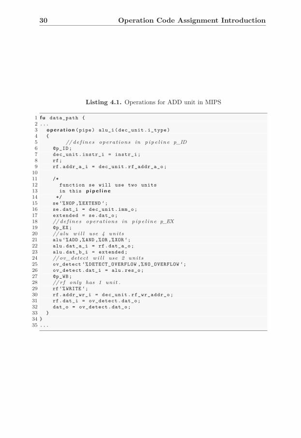
30 Operation Code Assignment Introduction
Listing 4.1. Operations for ADD unit in MIPS
1 fu data_path {
2 ...
3 o p e r a t i o n (pipe) alu_i(dec_unit.i_type)
4 {
5 // d e f i n e s opera t ions in p i p e l i n e p_ID6 @p_ID;
7 dec_unit.instr_i = instr_i;
8 rf;
9 rf.addr_a_i = dec_unit.rf_addr_a_o;
10
11 /*
12 function se will use two units
13 in this p i p e l i n e
14 */
15 se ‘%NOP ,%EXTEND ‘;
16 se.dat_i = dec_unit.imm_o;
17 extended = se.dat_o;
18 // d e f i n e s opera t ions in p i p e l i n e p_EX19 @p_EX;
20 // a lu w i l l use 4 u n i t s21 alu ‘%ADD ,%AND ,%OR ,%XOR ‘;
22 alu.dat_a_i = rf.dat_a_o;
23 alu.dat_b_i = extended;
24 // ov_detect w i l l use 2 u n i t s25 ov_detect ‘% DETECT_OVERFLOW ,% NO_OVERFLOW ‘;
26 ov_detect.dat_i = alu.res_o;
27 @p_WB;
28 // r f only has 1 un i t .29 rf ‘%WRITE ‘;
30 rf.addr_wr_i = dec_unit.rf_wr_addr_o;
31 rf.dat_i = ov_detect.dat_o;
32 dat_o = ov_detect.dat_o;
33 }
34 }
35 ...

4.3 A Tutorial for OpCode Assignment 31
tions listed in Table 4.1. In other words, the processor modeled by NoGap
may get the compatibility with MIPS instructions sets. Since NoGap is notable to accept all formats of MIPS instructions, I just implemented part ofMIPS instructions sets.
The instructions in this table are only I-type instructions, because theother types of instructions in MIPS have different instruction format whichcan not be supported by the current version of NoGap. For instance, theformat of R-type 1 instruction is not supported by NoGap, because thereis no immediate value in that type of instructions.
According the inputs in Listing 4.1, NoGap will finally generated 16 in-structions. Listing 4.2 shows these instructions with default OpCode valueswithout OpCode customization. The immediate data, port numbers andtiming have been ignored for simplification.
Listing 4.2. Operations for ADD unit
1 /*
2 * The first filed before the colon is opcode value ,
3 * for example 5<16>u00 shows the opcode value is 00 in
4 * hexadecimal format and its length is 5.
5 * The next part is the character opcode
6 * showing what the instruction is.
7 */
8
9 /* opcode value ************** character opcode *********************/
10
11 5<16>u00: alu.%ADD ,ov_detect .% DETECT_OVERFLOW ,rf.%WRITE ,se.%NOP
12 5<16>u01: alu.%ADD ,ov_detect .% DETECT_OVERFLOW ,rf.%WRITE ,se.% EXTEND
13 5<16>u02: alu.%ADD ,ov_detect .% NO_OVERFLOW ,rf.%WRITE ,se.%NOP
14 5<16>u03: alu.%ADD ,ov_detect .% NO_OVERFLOW ,rf.%WRITE ,se.% EXTEND
15 5<16>u04: alu.%AND ,ov_detect .% DETECT_OVERFLOW ,rf.%WRITE ,se.%NOP
16 5<16>u05: alu.%AND ,ov_detect .% DETECT_OVERFLOW ,rf.%WRITE ,se.% EXTEND
17 5<16>u06: alu.%AND ,ov_detect .% NO_OVERFLOW ,rf.%WRITE ,se.%NOP
18 5<16>u07: alu.%AND ,ov_detect .% NO_OVERFLOW ,rf.%WRITE ,se.% EXTEND
19 5<16>u08: alu.%OR ,ov_detect .% DETECT_OVERFLOW ,rf.%WRITE ,se.%NOP
20 5<16>u09: alu.%OR ,ov_detect .% DETECT_OVERFLOW ,rf.%WRITE ,se.% EXTEND
21 5<16>u0a: alu.%OR ,ov_detect .% NO_OVERFLOW ,rf.%WRITE ,se.%NOP
22 5<16>u0b: alu.%OR ,ov_detect .% NO_OVERFLOW ,rf.%WRITE ,se.% EXTEND
23 5<16>u0c: alu.%XOR ,ov_detect .% DETECT_OVERFLOW ,rf.%WRITE ,se.%NOP
24 5<16>u0d: alu.%XOR ,ov_detect .% DETECT_OVERFLOW ,rf.%WRITE ,se.% EXTEND
25 5<16>u0e: alu.%XOR ,ov_detect .% NO_OVERFLOW ,rf.%WRITE ,se.%NOP
26 5<16>u0f: alu.%XOR ,ov_detect .% NO_OVERFLOW ,rf.%WRITE ,se.% EXTEND
1This group instructions have no immediate data field and their OpCodes have the
same values. A function code at the end of instruction is used to differentiate this type
of instructions

32 Operation Code Assignment Introduction
4.3.1 Define the Instruction and OpCode Size
The OpCode size in Listing 4.2 is 5 which is not we expect of. Table 4.1shows OpCodes in MIPS have size 6, so we should define the size in the fu
data_path block as following:opcode_size 6;.
I always suggest users to firstly consider and configure the size of OpCode
and instruction before any operation code assignments. Because The OpCode
size limits the maximum number you may use on OpCode assignment, andthe instruction size must be greater than the OpCode size. For example, ifOpCode size is 20, then the maximum value of the OpCode is 220-1. Fur-thermore, the generator has a default OpCode size calculated with the totalamount of OpCodes in the current Mase, so the OpCode size must be notless than the default size also.
4.3.2 How to assign OpCode
Next, we need to assign the OpCodes in Table 4.1 manually. These assign-ments have been shown in Listing 4.3. An operation code assignment shouldalways be in the operation block and start with the keyword opcode. Thecharacter OpCode is used to define what OpCodes are going to be assigned.In Listing 4.3, values on the right hand side of the expression are decimalnumbers, but the binary or hexadecimal number can be used as assigningvalue also. For example, 6<2>000001 defines a value with 6 bit length inbinary format.
4.3.3 Auto-completion and Range Assignment
The operation code assignment generator also support auto-completion andrange assignment. The auto-completion functionality allows users to ignoresome sub operations in anOpCode assignment. For example, the sub oper-ation rf.%WRITE can be ignored in the assignment on line 13, because theFU rf under the phase p_WB only has one operation WRITE and the genera-tor can detect there is a missing sub operation and complete the definitionautomatically.
However, if we ignore a sub operation which has more than one possibleusages, the generator with auto-completion will finally generates all possibleOpCodes. For instance, if the assignment on line 15 in Listing 4.3 ignoressub operations in the alu, we will get all possible candidate OpCodes whichare combined
se.%NOP,ov_detect.%NO_OVERFLOW,rf.%WRITE

4.3 A Tutorial for OpCode Assignment 33
Listing 4.3. Operation Code Assignment for instructions in the ADD unit
1 fu data_path {
2 ...
3 o p e r a t i o n (pipe) alu_i(dec_unit.i_type) {
4 ...
5 /*
6 * The following FU names and their possible operations
7 * have been declared in the FU usage lists under phases
8 * These declarations can be found
9 * in Listing 4.1
10 */
11 opcode{
12 //ADDI ( with over f l ow )13 {se.%EXTEND ,alu.%ADD ,ov_detect .% DETECT_OVERFLOW ,rf.% WRITE} = 8;
14 //ADDIU ( no over f l ow )15 {se.%NOP ,alu.%ADD ,ov_detect .% NO_OVERFLOW ,rf.% WRITE} = 9;
16 //ANDI ( no over f l ow )17 {se.%NOP ,alu.%AND ,ov_detect .% NO_OVERFLOW ,rf.% WRITE} = 12;
18 //ORI ( no over f l ow )19 {se.%NOP ,alu.%OR ,ov_detect .% NO_OVERFLOW ,rf.%WRITE} = 13;
20 //XORI ( no over f l ow )21 {se.%NOP ,alu.%XOR ,ov_detect .% NO_OVERFLOW ,rf.% WRITE} = 14;
22 }
23 }
24 }
with operations in the FU alu. All possible completed OpCodes are shownin Table 4.3.3, it is notable that the only difference for these completedOpCodes is the sub operations from FU alu.
se.%NOP,ov_detect.%NO_OVERFLOW,rf.%WRITE
se.%NOP,alu.%ADD,ov_detect.%NO_OVERFLOW,rf.%WRITE
se.%NOP,alu.%AND,ov_detect.%NO_OVERFLOW,rf.%WRITE
se.%NOP,alu.%XOR,ov_detect.%NO_OVERFLOW,rf.%WRITE
se.%NOP,alu.%OR,ov_detect.%NO_OVERFLOW,rf.%WRITE
Table 4.2. All possible OpCodes generated by the incomplete OpCode definition
To finish the incomplete assignment se.%NOP,ov_detect.%NO_OVERFLOW,
rf.%WRITE, users have to use a range of values as the right hand side op-erator, because there are four OpCodes waiting for assigning. Listing 4.4shows the range assignments for the incomplete OpCode. There are totalfive available values in the range [14:10]. The range assignment can becompleted successfully, except a warning message will be arise to inform

34 Operation Code Assignment Introduction
users that only four values in the range have been used.The size of range should be always greater than the amount of assigning
OpCodes. For example, if the range [14:12] 2 is used to assign OpCodeslisted in Table 4.3.3, an critical error will terminate the processing, becausethe amount of values in the range [14:12] are not enough for all OpCodes.The values assigned to OpCodes in range assignment are not in order and
Listing 4.4. Operation Code Assignment with Auto-completion
1 ...
2 opcode{
3 /*
4 * The range [14:10] means there are 5 decimal
5 * numbers in that range . They are 10, 11, 12,
6 * 13 and 14.
7 */
8 {se.%NOP ,ov_detect .% NO_OVERFLOW ,rf.% WRITE} = [14:10];
9 }
may be any numbers in the range. The range assignment only helps usersto specify certain OpCodes in a range space. If users want to assign specificvalues to OpCodes precisely, they should assign values to OpCodes one byone.
Some important guidelines should be followed for the assignment. Usersmay overwrite operation codes in OpCode assignment, but they should checkthe assigned value carefully, guarantee assigned values are unique and valid.When users define a range for the assignment, the range upper limit shouldalways be greater than the lower limit, if not an error will be generated.What’s more, the range size must be large enough to make sure all OpCodescan get a value from the range.
After the operation code customization, OpCode’s values in these in-structions are same as values in MIPS architecture. The results are listedin Listing 4.5. We can find that OpCodes on line 3, 5, 10, 15, 20 havebeen assigned with correct values. The size of OpCode has been 6 now, andthe instruction size can be set with keyword instruction_size as well.But the default instruction size has been 32 bits, it is no necessary to setinstruction size again.
4.3.4 OpCode Exclusion
In Listing 4.5, there are still some unnecessary instructions. OpAssignGenoffers exclusion functionality to eliminate the OpCodes we don’t want to
2the range size is 3, the range has number 12, 13 and 14.

4.3 A Tutorial for OpCode Assignment 35
Listing 4.5. Instructions after Operation Code Assignment
1 6<16>u00: alu.%ADD ,ov_detect .% DETECT_OVERFLOW ,rf.%WRITE ,se.%NOP
2 //ADDI3 6<16>u08: alu.%ADD ,ov_detect .% DETECT_OVERFLOW ,rf.%WRITE ,se.% EXTEND
4 //ADDIU5 6<16>u09: alu.%ADD ,ov_detect .% NO_OVERFLOW ,rf.%WRITE ,se.%NOP
6 6<16>u01: alu.%ADD ,ov_detect .% NO_OVERFLOW ,rf.%WRITE ,se.% EXTEND
7 6<16>u02: alu.%AND ,ov_detect .% DETECT_OVERFLOW ,rf.%WRITE ,se.%NOP
8 6<16>u03: alu.%AND ,ov_detect .% DETECT_OVERFLOW ,rf.%WRITE ,se.% EXTEND
9 //ANDI10 6<16>u0c: alu.%AND ,ov_detect .% NO_OVERFLOW ,rf.%WRITE ,se.%NOP
11 6<16>u04: alu.%AND ,ov_detect .% NO_OVERFLOW ,rf.%WRITE ,se.% EXTEND
12 6<16>u05: alu.%OR ,ov_detect .% DETECT_OVERFLOW ,rf.%WRITE ,se.%NOP
13 6<16>u06: alu.%OR ,ov_detect .% DETECT_OVERFLOW ,rf.%WRITE ,se.% EXTEND
14 //ORI15 6<16>u0d: alu.%OR ,ov_detect .% NO_OVERFLOW ,rf.%WRITE ,se.%NOP
16 6<16>u07: alu.%OR ,ov_detect .% NO_OVERFLOW ,rf.%WRITE ,se.% EXTEND
17 6<16>u0a: alu.%XOR ,ov_detect .% DETECT_OVERFLOW ,rf.%WRITE ,se.%NOP
18 6<16>u0b: alu.%XOR ,ov_detect .% DETECT_OVERFLOW ,rf.%WRITE ,se.% EXTEND
19 //XORI20 6<16>u0e: alu.%XOR ,ov_detect .% NO_OVERFLOW ,rf.%WRITE ,se.%NOP
21 6<16>u0f: alu.%XOR ,ov_detect .% NO_OVERFLOW ,rf.%WRITE ,se.% EXTEND
keep. For example, MIPS instruction sets have no instructions XOR andOR with overflow detection, so OpCodes on line 17 and 12 are useless. Wecan exclude these OpCodes easily with the symbol ‘!’. Listing 4.6 showshow to exclude OpCodes. When we exclude an OpCode, we should check the
Listing 4.6. Operation Code Exclusion
1 ...
2 opcode{
3 !{alu.%XOR ,ov_detect .% DETECT_OVERFLOW ,rf.%WRITE ,se.%NOP};
4 !{alu.%OR ,ov_detect .% DETECT_OVERFLOW ,rf.%WRITE ,se.% NOP};
5 }
existence of OpCode firstly and make sure the OpCode has not been assignedpreviously. Excluding OpCodes which have been excluded or assigned arevalid, but certain warnings messages will prompt to inform the abnormalbehaviors. One important thing is we cannot use incomplete OpCode toexclude multiple OpCodes in one statement, because excluding OpCodes isdangerous action for the generator. To make sure all OpCodes are excludedcorrectly, all exclusions should be defined clearly
With the Verilog generator in NoGap, the example in Listing 4.1 willfinally get the hardware implementation. In Chapter 8, the output will be

36 Operation Code Assignment Introduction
synthesized to verify the hardware implementation.
4.4 OpAssignGen Configuration
Finally, I want to introduce how to configure the OpAssignGen. As men-tioned in Section 3.8, the generator can be configured with an XML controlflow file. In this file we may set what generator we want to use and which op-tions will be used on the generator. OpAssignGen has two options: verbose
and autocomplete. Listing 4.7 shows how to configure the OpAssignGen.
Listing 4.7. OpAssignGen Configuration
1 <generator type="gen_assign_opcodes " >
2 <option >verbose </option >
3 <option >autocomplete </option >
4 </generator >
OpAssignGen is specified with name: “gen_assign_opcodes” in the flowfile. The <option> label marks what options are enabled. When the ver-bose option is set, all level of information will be printed by the generator.The autocomplete option will turn on the auto-complete functionality, anincomplete OpCode declaration will be completed automatically.

Chapter 5
OpCode Assignment Syntax
5.1 Introduction
To customize the operation code value, exclude operations, and adjust in-struction and OpCode size in NoGap, current NoGapCL must be extended.This chapter aims to introduce the new OpCode assignment grammar, anddescribe the idea behind the grammar.
5.2 Design of Assignment Grammars
When we extend grammar for some languages, the most important guide-line is to follow the syntax style in the old language. The new OpCode
assignment grammars should be familiar by users easily, so I need to makesure the new grammar is integrated well.
An OpCode assignment is made up of two parts: OpCode definition andvalue or range. The OpCode definition is left hand side operator, and thevalue or range is right hand side operator. These two operators are con-nected with the symbol ‘=’, so the operation code assignment looks like avariable assignment.
The format of OpCode definition borrows from the character OpCode
format in the instruction manual generated by NoGap. The characterOpCode format is used by NoGap globally to help users distinguish dif-ferent OpCodes. It is readable well for human, although this format is notconvenient when assigning lots of OpCodes. The detailed explanation aboutcharacter OpCode can be found in Section 4.1.1.
A typical OpCode definition is composed by one or more sub operations,and a sub operation contains a FU name and usage name, e.g. t1.%ADD. FUand usage name are connected with operator ‘ . ’, the dot operator is a good
37

38 OpCode Assignment Syntax
connector, because it shows the relation that the usage is one of elementsin the FU. A pair of curly brackets around the OpCode definition helpscompiler to find the beginning and end of definition. The original characterOpCode format use square brackets to mark the definition, e.g. [t1.%add,
t2.%sub], but the symbol, square bracket, has been used to declare a valuerange in NoGapCL. If the square bracket was used in OpCode definition,a shift reduce error would be arise by the compiler, since the syntax isambiguous for the compiler.
When users eliminates OpCodes, an OpCode definition starts with symbol‘!’ tells the generator what OpCode should be excluded from operations.This symbol clearly shows the intention of the statement, and it is alsosimple to use for those who are familiar with C-like languages.
Anyhow, all OpCode assignments and exclusion should be in a blockstarts with the keyword opcode. This keyword tells the compiler and gener-ator that the following statements are OpCode assignment statements. Theopcode block is placed in the operation block, and different operation
block has their own opcode block also. This strategy helps user to handlethe right OpCodes in the right place.
On the other hand, the instruction size and OpCode size are differentwith the OpCode assignment. I consider both of two sizes as constant vari-ables in NoGap. These two variables are important attributes for Mase
unit. In other words, the instruction size and operation code size can onlybe initialized at the beginning and overwritten is not allowed. Like what atypical programming languages does for the initializing, the two keywords,instruction_size and opcode_size, are also constant variable names andfollow a numerical number as initial value. This two variables are globalvariables, in other words, they can only be initialized one time. What’smore, all FUs have the same operation code and instruction size.
5.3 Grammar for Assigning OpCode
As mentioned before, the grammar for OpCode assignment is clear andsimple to use. The following sections will show the assignment and exclusiongrammar in Backus-Naur Form (BNF) format.
5.3.1 Opcode Block
Grammar 5.1 opcode statement
〈opcode_cons〉→opcode{ 〈opdef_stmts〉 }

5.3 Grammar for Assigning OpCode 39
Grammar 5.1 shows how to start OpCode assignment with the opcode key-word. All OpCode assignments or exclusions in NoGapCL take place withinan opcode block and the opcode block is in an operation block whichdefines the pipelined operation. An example of operation block can befound in Listing 4.1 (And more examples of completed operation bolckscan be found in [4].)
5.3.2 Operation Code Definition
Grammar 5.2 opcode assignment grammar
〈opdef_stmts〉→〈opdef_stmts〉 〈opdef_stmt〉| 〈opdef_stmt〉 | ∅
〈opdef_stmt〉→〈opdef_list〉 = 〈const_num〉| 〈opdef_list〉 = 〈range〉| 〈opdef_list〉 = 〈op_const_list〉| !〈opdef_list〉
The operation code assignment within opcode block assigns one or morevalues to the OpCodes. This assignment grammar is shown in Grammar 5.2.All operation code assignments and exclusions in the opcode block arenamed as opdef_stmts. One or more opdef_stmt construct the opdef_stmts,and an opdef_stmt stands for one operation code assignment or exclusion.
Moreover, the last line on Grammar 5.2 shows how to exclude theOpCode which users do not want to use. All excluded OpCodes will bedeleted from the Mase and never be assigned.
Grammar 5.3 OpCode definition grammar
〈opdef_list〉→{ 〈opdef_list〉 , 〈opdef〉 }〈opdef〉→ 〈fu_id〉.〈clause_name〉
The opdef_list in Grammar 5.3 declares which OpCode will be usedin the assignment. The opdef_list is composed by multiple opdef ele-ments. These elements defines what FU and which usage will be used inthis OpCode.
More OpCode assignment examples and some notices are shown in Sec-tion 4.3.

40 OpCode Assignment Syntax
5.3.3 Grammar for define OpCode and instruction size
The size of OpCode and instruction is the length of bits in OpCode valueand instruction respectively. This size definition is placed in the FU block.Grammar 5.4 shows how to use the two keywords instruction_size andopcode_size to set the size of instruction and OpCode.
Grammar 5.4 OpCode and instruction size definition grammar
〈instruction_size〉→ instrucion_size 〈const_num〉〈opcode_size〉→opcode_size 〈const_num〉

Chapter 6
OpCode Assignment
Generator
The OpAssignGen is implemented to complete three tasks:
• Instruction and OpCode size customization
• OpCode assignment
• OpCode exclusion
The first task is to allow users to adjust the instruction or operation codesize. For example, setting the instruction size to 64 will get a 64bit lengthinstruction sets at last.
The OpCode assignment is core business for my generator, which userscan define OpCodes’ value according their own requirements.
The last task, OpCode exclusion, is to allow users to eliminate OpCodesfrom Mase, Normally, we can exclude unused OpCodes or any OpCodes.Excluded OpCodes will never appear in the instruction sets. This exclusionaction will also decrease the number of final instruction in the processors.
6.1 Procedures of OpCode assignment
As mentioned in Chapter 4, The declaration of FU usage list defines thecorresponding operations for every phase/pipeline in the operation block.OpCodes are combination of these operations and represent all of possibleinstructions can be executed by the processor.
OpCodes are assigned automatically by NoGap. If we want to customizecertain OpCode values, the first important thing is let NoGap knows whatOpCodes are going to be assigned and what their values are. Because we
41

42 OpCode Assignment Generator
havenf’t such grammars to allow users assign OpCodes, the first step is toextend current grammars. The extended grammars have been explained inChapter 5. At next step, we need to extend NoGap scanner and parser, thenNoGap can understand the new assignment grammar and add new nodesto ASTs. The extension of scanner and parser are shown in Section 6.2.Next, a new generator should be implemented to process corresponding newassignment nodes in every PU’s AST and finally complete the assignmentsor report errors.
The process of operation code assignment can be split into three steps:get OpCode assignments, verify assignments and finish assignments.
Getting OpCode assignments from AST is relative simple, the new gen-erator only needs to traverse the AST in all PUs to detect if there is OpCode
assignment and fetch corresponding assignment statement nodes to get nec-essary data such as what the type of OpCode assignment is, which OpCodesare going to be assigned and what the values are. At this point, the newgenerator will also handle the semantic error due to incorrect OpCode as-signments.
When the assignment data have been known, verifying these assign-ments is the next important step for the generator. The verification ofassignment can also be split into two steps: verify the definitions of OpCode
in assignments and check if assigned values are valid. Before the processof operation code assignments, all OpCodes in every Mase have been gener-ated. A container at PU keeps all OpCode objects represented by the classOpCode. Then, the verification of OpCodes is just to search the containerand check the existence of OpCodes. For the validity of assigning values,the generator should make sure these values are unique and unused. Onthe other hand, if the OpCode assignment is range assignment, the amountof available values will be check also. Actually, there are more verificationprocedures during OpCode assignments. For example, the generator needsto check if the OpCode has been assigned. The assignment processing flowand most of verification procedures will be explained in Section 6.5.
The new generator will finally assign values to corresponding OpCode
objects mentioned above, if the assignment passes all checks. Then, othergenerators in NoGap continue to process PUs and combine OpCode andimmediate data to an instruction at last.
6.2 Scanner and Parser Extension for OpAssignGen
Because of the new elements and grammars in NoGapCL, the scanner andparser should be extended. Firstly, the keywords used in the new grammar

6.3 Representation of OpCode 43
are added to the lex file, then these keywords can be recognized as tokensin the parser later. The three new keywords and their returned tokenshave been shown in the Listing 6.1. The keyword instruction_size andopcode_size have been introduced in Section 5.3.3. The keyword opcode
on line 3 marks the beginning of operation code assignment.
Listing 6.1. Keyword Definitions for OpCode Assignment
1 "instruction_size" { r e t u r n TT_INSTRUCTION_SIZE ; }
2 "opcode_size" { r e t u r n TT_OPCODE_SIZE; }
3 "opcode" { r e t u r n TT_OPCODE; }
The next step is to configure the parser. Then the parser can recognizethe new grammar and insert corresponding nodes into the AST. As men-tioned in Section 3.3, Bison is used to construct the NoGap parser. List-ing 6.2 shows a part of definitions for the new OpCode assignment grammar.
Listing 6.2. OpCode Assignment Definition in the Parser
1 opdef_stmt: opdef_simple_stmt ’=’ const_num ’;’
2 {
3 | opdef_simple_stmt ’=’ op_const_stmt ’;’
4 {
5 $$ = insertNode(parse_data.ast(),info:: OpAssignList (),
6 info:: EdgeOrder (),$1 ,$3 ,@$.first_line );
7 }
8 ...
The inserNode function on line 5 will insert a node named OpAssignList
into the AST. The information about node insertion and parser rule defini-tion have been listed in Section 3.3. All statements, identifiers and keywordsfor the OpCode assignment will be inserted into AST as nodes. The moredetailed list about the definition for the parser extension can be found inAppendix B. Table 6.1 shows all node types for the operation code assign-ment.
6.3 Representation of OpCode
The representation of OpCode is kept in the OperationInfo class. Beforethe OpAssignGen starts its process, all possible OpCode combinations havebeen saved in the data structure arch_data::v2::OperationCodes. As

44 OpCode Assignment Generator
Table 6.1. Vertex type
Node Type Explanation
InstructionSize The root node for instruction size definitionOpCodeSize The root node for OpCode size definitionOpCode The root node for OpCode assignment blockOpAssignStmts The root node for all OpCode assignments and exclusionsOpAssign The root node for one value OpCode assignmentOpAssignList The root node for list OpCode assignmentOpAssignRange The root node for range OpCode assignmentOpExclude The root node for OpCode exclusionOpCodeDec The node for OpCode declarationOpConstList The root node for a list of constant number
mentioned in Section 6.1, the OperationCodes will be searched by mygenerator to find the matched OpCode objects.
From Figure 6.1, we know the vector container operation_codes_m
in OperationCodes holds the operation code objects. And the operationcode is represented with OpCode class. This class is composed by multipleOpCodeSlices. The slice looks like t1.%ADD which is represented with theFuUsage class. On the other hand, the numerical OpCode is representedwith the class NumericOpCode.
The friend class AssignOpHandler is instantiated by my generator,which will be introduced in Section 6.6. This handler is responsible forprocessing OpCodes in the OperationCodes.
6.4 Data Structure in OpAssignGen
As mentioned in Section 3.6, the data and tables containing assigned andexcluded OpCodes are kept by another class separated with the genera-tor action part. A simple type, arch_data::AssignOpCodes, wrappedby Generated<DATA>1 is used to hold all data for OpAssignGen. Ex-cept the operation codes table, some methods are implemented in theAssignOpCodes class as the operation interface. Line 5 in Listing 6.3 showsthe most important table, the operation code table, which keeps all OpCodescustomized by users. This table uses the bimap in boost library [12] asOpCode container. A bimap is a data structure that represents bidirec-
1This wrapper has been explained in Section 3.6.

6.4 Data Structure in OpAssignGen 45
Figure 6.1. OpCode representation UML
Listing 6.3. AssignOpCodes Definition
1 c l a s s AssignOpCodes : p u b l i c policy :: OutStreamable
2 {
3 ...
4 typede f boost :: bimaps ::bimap <boost :: bimaps ::set_of <utils ::BitNum >,
5 boost :: bimaps :: unordered_set_of <table_entry_t > > optable_t;
6 ...
7 };

46 OpCode Assignment Generator
tional relations between elements of two collections. The left collection,BitNum, in the container represents a big int. The value of BitNum can beprinted in hexadecimal or decimal easily with fixed or unfixed length. Themain reason I use bimap is due to the bidirectional constraints between theOpCode and its value. Both OpCode and its value are key elements, whichmeans they must be unique in the map.The mapping relation between thetwo mapped types are same. The mapping from value to OpCode is injectiveand vice versa.
There are some important assignment rules I need to mention again.The OpCode value can be overwritten multiple times, but only the last as-signed value is valid and kept in the table. If the assigned value has been inthe table, the generator would raise an error issue and terminate processing.Listing 6.4 shows some OpCode overwriting examples. The overwriting online 3 to line 7 are correct. However, the value 3 used in the assignment online 13 has been assigned to the OpCode t1.%ADD,t2.%ADD,jump_cond.%F0,which leads to an error issue finally.
Listing 6.4. operation code overwriting examples
1 ...
2 opcode {
3 {t1.%ADD ,t2.%ADD ,jump_cond .%F0} = 0;
4 {t1.%ADD ,t2.%ADD ,jump_cond .%F0} = 2;
5 // the OpCode : [ t1 .%ADD, t2 .%ADD, jump_cond.%F0 ] f i n a l l y has va lue 36 {t1.%ADD ,t2.%ADD ,jump_cond .%F0} = 3;
7 {t1.%SUB ,t2.%OR ,jump_cond .%F0} = 2;
8 /*
9 * Value 3 is not valid number.
10 * Overwriting OpCode is allowed ,
11 * but OpCodes should have a unique value.
12 */
13 {t1.%SUB ,t2.%OR ,jump_cond .%F0} = 3;
14 }
15 ...
16 }
6.5 OpAssignGen Process Flow
The OpAssignGen is made up of two classes, Generator::AssignOpCodes
and Generator::AssignOpHandler. The AssignOpCodes represents theoperation code assignment generator. The AssignOpHandler is a help classwhich helps the generator to perform the OpCode assignment and verifica-tion. In a normal input file, one Mase has one or more operation blocks.

6.5 OpAssignGen Process Flow 47
To save the resource, the AssignOpHandler will only be initialized, whena valid operation code assignment is found in the operation block. Afterthe handler finishes its work, it will be released immediately.
Figure 6.2 shows the generator processing flow. All generators regis-tered in the default_registration will be initialized when NoGap starts.Then, in the flowchart, it assumes the operation code assignment genera-tor has been initialized. As mentioned in Section 3.7, every generator willperform initializing as well as finalizing work after generator initializationand before generator release. The flowchart ignores these two stages, be-cause there is nothing to do for the OpAssignGen in the initialization andfinalization stage. When the generator starts and prepares to process PUs,it will firstly detect whether the data member MaseOperation in the PU
has been initialized. The instance of type MaseOperation contains all pos-sible operation codes combinations and operation information. The moredetailed introduction about MaseOperation has been shown in Section 6.3
If everything is fine, the operator() function in the generator will beinvoked, which marks the processing stage starts. The first operation inthis stage for the OpAssignGen is to calculate how many bits we need torepresent a numerical OpCode. The calculation method has been shownin Section 4.3.1. Next, the generator checks whether there is a valid usercustomized OpCode length. If the user defined length is less than the defaultvalue, the generator will terminate immediately and report an error.
Next, the generator will try to search a symbol type info::Operation
in the symbol table. If no Operation symbol is found, it means there isno operation and opcode block in the current PU , then the generatorgoes to END step directly. Assuming the generator finds the Operation
symbol, it will get the corresponding operation vertex descriptors fromthe symbol table, and then save all operation vertex descriptors into a listfor further processing. After that, the generator goes to check the generatoroptions setting in the XML based control file. There are two options forthe OpAssignGen: verbose and autocomplete. Option verbose asks thegenerator to print the info messages in all levels. When autocomplete
turns on, the generator can handle incomplete OpCode assignments.
After checking these options, the generator will pick one operation ver-tex from the list and do further checks. The first check is to find whetherthe operation vertex has one or more sub vertices named OpAssignStmts
and then check further if there is a sub vertex under the OpAssignStmts.These checks make sure that current PU has operation code assignment.Then the AssignOpCodes initializes an AssignOpHandler to process theoperation code assignments one by one. For example, the handler needs

48 OpCode Assignment Generator
Figure 6.2. OpCode Assignment Flowchart

6.6 Structure of AssignOpHandler 49
to process 3 OpCode assignments and one exclusion in List A.2. The de-tailed assignment validation and processing will show in Section 6.6. Afterprocessing the OpCode assignments in the current operation block, the gen-erator will pick a new operation vertex and repeat the checks mentionedabove. When all operation vertices have been handled, the generator willassign values to the remaining OpCodes which are not assigned by users.
Finally, the generator will print all user customized operation codes andtheir values if the option verbose has been set, and reset the generator forprocessing the next PU.
6.6 Structure of AssignOpHandler
Figure 6.3 shows the UML diagram of AssignOpCodes and AssignOpHandler.The most important attributes, methods and the relationship between theseclasses have been listed in the figure. As mentioned in the Section 6.5, after
Figure 6.3. AssignOpHandler and AssignOpCodes UML

50 OpCode Assignment Generator
some initialization works, the OpAssignGen will try to traverse the ASTto find a vertex named operation. The member method find_operation
in class AssignOpCodes is used to find the corresponding operation vertex.When we get the operation vertex and verify the operation vertex has subvertices named OpAssignStmts, the AssignOpHandler will be initialized bythe generator. The UML figure shows the associate relationship betweenthe handler and generator class.
The class AssignOpHandler is the core for the OpAssignGen. It verifiesthe user defined OpCodes as well as their assigned values, handles errors andwarnings and saves the assigned and excluded OpCodes to the correspondingcontainers. The constructor of class AssignOpHandler can be found inListing C.2 at Appendix C.
In Figure 6.3, the two assign_opcode functions in AssignOpHandler
are both used to assign the user customized OpCode value. The difference isthe first version of assign_opcode only accepts one value and assigns oneOpCode, while the second version accepts a list of values and also handlesmultiple OpCodes. Actually, the process flow of this two version of functionsare similar.
6.6.1 Processing Flow for AssignOpCodeHandler
Listing 6.5. Simple OpCode Assignment Example
1 fu data_path
2 {
3 ...
4 o p e r a t i o n (pipe) op3(dec_unit.type_b)
5 %OP3 {
6 ...
7 @P0;
8 @P1;
9 t1 ‘%SUB ‘;
10 @P2;
11 t2 ‘%AND ‘;
12 @P3;
13
14 opcode
15 {
16 {t1.%SUB ,t2.%AND} = 20;
17 }
18 }
19 ...
20 }
Listing 6.5 shows a simple operation code assignment. The AST gener-

6.6 Structure of AssignOpHandler 51
ated from this input is shown in Figure 6.4. I will use this simple exampleto illustrate how the operation code assignment is processed by the handler.To simplify the example, other nodes in the AST have been ignored. Beforeillustrating the processing flow in the handler, I hope to repeat the OpCode
assignment flow. When users want to do OpCode assignment, they shoulddesignate what OpCode they want to assign. Next, they should give one ormore values to corresponding OpCodes. In Section 6.1, we have known thattwo key points for OpCode assignment. They are OpCode and value verifi-cation respectively. The following check list shows what will be verified bythe handler.
• The customized OpCodes exist.
• OpCodes are not assigned previously (if OpCode have been assigned,the generator will return a warning)
• The values assigned to OpCodes are correct
• The assigned OpCodes value are unique.
To finish the OpCode assignment shown in Listing 6.5, the handler needsthe following steps to verify and assign value.
1. check whether the value assigned to OpCode is valid. For example, inthe Listing 6.5, the handler will search the opcode table to verify thatvalue 20 is not in the table and less than the maximum number.
2. check the amount of sub operation for the OpCode is correct.
The format of sub operation has been introduced in Section 6.3. Nor-mally, OpCode is composed of multiple sub operaton. And the numberof sub operation in the OpCode is decided by the amount of operationunits declared in advance under the phases block. We also call suboperation as OpCode slice.
In Listing 6.5, there are only two units declared in the phase P1 andP2. So a valid OpCode declaration in the assignment should onlycontain two sub operations.
The handler will scan the AST to get the number of sub operationsused in the assignment statement. Figure 6.4 shows of there are twosub operations under the OpCodeDec nodes, which is t1.%SUB andt2.%AND respectively.
3. if the number of sub operation in the assignment statement is greaterthan the correct number, the warning_handler is invoked to termi-nate processing and report error

52 OpCode Assignment Generator
Figure 6.4. A Simple AST generated from the Assignment in Listing 6.5

6.6 Structure of AssignOpHandler 53
If the number is less than we expect, the generator will assume thereis an incomplete assignment, and then the generator starts to to gen-erate all possible OpCode combinations.
4. In this step, the handler generates the character format OpCodes basedon the AST traverse result. This character format, table_entry_t,has been introduced in Section 6.4.
5. The handler checks the validation of OpCodes in character format. Ifthe handler doesn’t find any matching OpCode in the OperationCodes,an error is reported. If the corresponding OpCode in the OperationCodes
is found, the reference to that entry will be passed to the handler.
6. check whether the OpCode has been assigned previously.
If the OpCode has been assigned, raise the OVERWRITING warning
7. if the statement is a range or constant list assignment, the handlerwill check that the available amount of values in that range or list isno less than the number of OpCodes in the assignment.
For example, if we use the range [1:0] to assign 3 OpCodes in a rangeOpCode assignment, this assignment will cause the RANGE_SMALL error.
8. check that the assigned value is not used previously, and raise an errorif the value is not unique. The handler will check the used_op_code
table in the arch_data::AssignOpCodes.
9. if every step above is OK, a class NumericOpCode will be instantiatedwith the assigned value in the corresponding OpCode object.
In List 6.5, the handler will finally insert the OpCode, t1.%SUB,t2.%AND,and its value into the optable locating at arch_data::AssignOpCodes.
Now, the OpCode assignment in the current operation block Op3 is fin-ished, the handler will be released, and a new handler instance will beinitialized by the generator if there are more operation blocks in the PU.
For OpCode exclusion, it is similar with assignment. The same checksare used on the exclusion to make sure the OpCodes trying to be excludedare valid. When everything is fine, the corresponding OpCode entries in theOperationCodes are removed. At the same time, the excluded opcode tablein arch_data::AssignOpCodes will keep the deleted OpCode as a backup.The notable thing for exclusion is we cannot use auto-complete in OpCode
exclusion, since deleting an OpCode from Mase is a dangerous behavior, anexplicit definition is necessary.

54 OpCode Assignment Generator
6.7 Instruction and OpCode Size Definition
As I introduced previously, the instruction and OpCode size can be cus-tomized by the user. With the size definitions, the length of instructionand numerical OpCode can be customized by user. This customization isvery important, especially for the OpCode assignment, because the lengthof numerical OpCode determines the greatest number of OpCode we mayassigned. For example, if we set the OpCode size equals to 3 , then the max-imum numerical OpCode is 0x7 and the total amount of OpCodes should beless than or equal to 8. These two definitions are defined out of operationblock. Users can only define these two sizes at one time. Overwriting orredefining them will result an error and terminate generator immediately.
The OpAssignGen processes the length assignment before it process-ing the OpCode assignment. The instruction and OpCode length are han-dled by two methods: get_and_assign_custom_instruction_size andget_and_assign_opcode_size in AssignOpCodes. The declaration of thesetwo methods have been shown in Figure 6.3.
Before handling the OpCode size defined by users, the generator will in-voke the function determine_opcode_size to calculate the default OpCode
size. After that, the two methods in the generator will search the AST toget the two nodes named OpCodeSize and InstructionSize respectively.After analyzing these two nodes, the generator will make sure there is noredefinition and that OpCode length is shorter than the instruction length.What’s more, the operation code size should be greater than the defaultoperation code size calculated previously. Finally, these two values will bepassed to current PU and kept as PU attributes. The default OpCode sizewill be replaced by the customizing value, but the instruction size will behandled later by the instruction format generator.
6.8 OpAssignGen Registration
Listing 6.6. OpAssignGen Registration
1 vo id default_registration(Register& reg)
2 {
3 ...
4 reg.register_generator <generator :: AssignOpCodes >
5 ("gen_assign_opcodes ");
6 ...
7 }
6.8 OpAssignGen Registration 55
If we want to use the OpAssignGen, it should be registered in NoGap
firstly. The generator register has been introduced in Section 3.7. List-ing 6.6 shows the generator registration for OpAssignGen. The functionregister_generator on line 5 instantiates the generator, and then insertsthe pointer of generator as well as the generator name into a map. The gen-erator registration is finished at the beginning of NoGap processing flow.Users can utilize the generator name gen_assign_opcodes to configure theOpAssignGen in the control flow file.


Chapter 7
NoGap Improvements and
suggestions
In this chapter, some improvements and suggestions will be given. I will fo-cus on the improvements about software functionality, such as the interface,API and error handling.
7.1 NoGap Error Detection and Handling
The error I mention here is caused by user inputs. The user inputs can causetwo types of error. They are syntax error and semantic error respectively.A syntax error is normally due to the spelling mistake or missing symbols.In NoGap, the syntax error is detected during the compile-time. Listing 7.1shows an input with the syntax error. On line 3, the semicolon is missed.NoGap can detect the syntax error successfully.
Listing 7.1. Input with Syntax Error
1 fu mage_test
2 {
3 i n p u t [31:0] dat_a_i
4 i n p u t [31:0] dat_b_i;
5 i n p u t [1:0] op_i;
6 output [31:0] res_o;
7 }
Listing 7.2 shows the prompting message returned by NoGap for thesyntax error. The message on line 1 indicates there is a syntax error and itsline number in the input file, but the line number is incorrect. What’s more,
57

58 NoGap Improvements and suggestions
the message on line 2 is not meaningful. An improvement for the NoGap
front-end should be made to give users more friendly information aboutwhat and where the error is. This improvement can be implemented simplywith certain Bison options. For instance, the macro YYERROR_VERBOSE
in Bison can generate more meaningful message except the plain Syntax
error message. After using this macro, the error message in list 7.1 willbecome Error: ’syntax error, unexpected IDENTIFIER, expecting
SEMICOLON’.
Listing 7.2. Syntax Error Information
1 4: Syntax error
2 nogap: parser.y:106: int ncdparse (): Assertion ‘false ’ failed.
3 Aborted
On the other hand, the semantic error detection is more complex thanthe syntax error detection. The semantic error may be detected by NoGap
parser during the compile-time, or generators during their parsing PUs.In NoGap, the ValidateIdentifiers generator is specified to validateidentifiers. According the predefined rules or actions, the validation gen-erator search identifier nodes in ASTs and validate nodes with recordingsin the symbol table. Currently, these validations are relative simple. Er-rors among different FU, and the instantiating a non-existing FU are notdetectable. The semantic error detection for various statements is hugework, one possible method to simplify the implementation is to requirethe generators to detect errors during their performance. Since generatorsmay developed by different developers, the error detection work can be dis-tributed easily. Actually, the identifier validations in the operation codeassignment are performed by the OpAssignGen.
Another possible improvement is the error handler CompileIssueHandler.Sometimes, the generator want to terminate its work immediately whenthere is a critical error. However, the generator can not terminate process-ing in real time, because all issues are handled until the generator finishingits work. A critical error issue may be added for the emergency termina-tion. When the critical error is raised, the handler may throw an exceptionto terminate processing right away.
7.2 Better API and Interface for NoGap
I think a good platform must have a good API. NoGap has offered aserious of API to traverse ASTs, visit PUs and do some conversions, most of

7.2 Better API and Interface for NoGap 59
containers in NoGap have exposed the iterators for read and write accesses.But APIs in NoGap are not categorized well. All help functions are putinto the same namespace without hierarchies, some assessors are missed orhidden in the implementation. For developers, a clean and multi-functionalAPIs are expected.
The generator structure gives NoGap a flexible layout to extend func-tionality. Generators are implemented as static libraries and configured bythe flow configuration file. This method also grantees that unused gen-erators will not be initialized, which saves the system resource, such asmemory on the heap. But this layout may be not a good method for com-mercial development. The NoGap system have to recompiled when a newgenerator is added. In addition, installing a new generator and making itswork is also not simple for normal users. I think the dynamical loading isgood alternative for current structure. With the dynamical loading, gener-ators may be complied to a single object file and loaded at run time. Thismechanism grantees the installation of generators is easy, the developmentof generator is independent and the loading of generators is controllable.
Furthermore, the interface of generator in NoGap should be extendedalso. Developers may easily implement a generator to extend NoGap func-tionality based on the simple interface. However, the generator interfaceis too simple to fulfill the further demands from developers. Developershave to implement their own data structures or methods to improve thegenerator. Normally, these behaviors will destroy the software encapsu-lation. For instance, current interface dose not define how to share dataamong different generators. If a generator want to pass data to anothergenerator, developers have to hack other generator and the PU structuresby themselves.


Chapter 8
Results
To introduce the new NoGap generator OpAssignGen for operation codeassignment, we firstly explained NoGap structure (Chapter 3) and the pur-pose of operation code assignment (Section 5.1). Secondly, we illustratednew grammars in Section 5.3 for operation code assignment and some mod-ifications in NoGap scanner and parser (Chapter 6). What’s more, we alsoexplained the idea of operation code assignment syntax format and whatits advantage is in Section 4.1. The implementation of OpAssignGen isintroduced in Chapter 6. To assistant users to use new OpAssignGen, asimple tutorial presented in Section 4.3. After that we will show somesynthesizing results which prove the customized operation code assignmentby OpAssignGen has only tiny effect for the logic HW design in next Sec-tion 8.1. Finally, we will mention some NoGap drawbacks and possibleimprovements in Chapter 7.
61

62 Results
8.1 Results of Synthesizing
After the operation code assignment for the input in Listing 4.1, we canfinally get some hardware implementation with the Verilog generator. Toverify the design, I synthesized the hardware implementation and decoderimplementation. Table 8.1 shows the two results which are implementa-tion with operation code customization and without customization respec-tively. The target device for synthesizing is Field Programmable Gate Ar-ray (FPGA) xc2v4000. We can find that the synthesized result for thedecoder implementation with customization has a tiny increase, comparedwith the result without operation code customization. This change showsthe operation code customization almost has no effect for the logic utilizein the decoder implementation.
Table 8.1. Synthesizing Results
Name Number of 4 input LUTs
HW Implementation (customized) 32 out of 46,080Decoder Implementation (customized) 29 out of 46,080HW Implementation 32 out of 46,080Decoder Implementation 28 out of 46,080

Chapter 9
Conclusions
Chapter 8 shows a successful result that the amount of used LUTs has a rea-sonable value compared with the result without operation code customiza-tion, Based this result, I can get the conclusion that my OpAssignGen isimplemented successfully. Due to the time limitation, I can not simulatethe hardware implementation and verify the result further. What’s more,the compatibility of MIPS instruction sets in my hardware implementa-tion is not verified also, since there is no possible simulator solution now.Anyhow, the operation code customization is a good extension for NovelGenerator of Accelerators and Processors (NoGap). It gives users morepossibilities to create a novel Hardware (HW) design. There is no doubtcurrent customization capability can not fulfill the designers’ requirements.Besides the operation code customization, NoGap needs a more flexibleinstruction format. Designers can not only adjust the size of instructionbut also alter the structure of instruction. For example, designer can addor remove bit fields in an instruction. NoGap has shown a good future forhardware design. Although this tool is still not maturity, it has a goodpotential to be improved.
63


Chapter 10
Future Work
Currently, the OpAssignGen lacks an important functionality: changing theposition of OpCode in the instruction. The instruction format in NoGap isnot adjustable now. This format has been explained in Section 4.1. Usersare not allowed to change the position of OpCode. This limitation effects theflexibility of NoGap and weaken compatibility. So, I will try to implementthis functionality in the future.
The initial idea is using the range assignment to display the positionduring the OpCode size customization. In Listing 10.1, I firstly defines the
Listing 10.1. Define the Position of OpCode in the Instructions
1 // the number used in the range i s decimal number .2 instruction_size 32;
3 opcode_size [31:28];
instruction size, so the length of instructions is 32 bit. Then, an operationcode size definition with a range is used on line 3 The range [31:28] in thisOpCode size definition has different meaning. This size definition finish twothings at the same time. It defines the OpCode is 4 bit length, and tellNoGap that OpCode should placed at bit 31 to bit 28, the beginning of theinstruction. This change of grammar allows users to set the position ofOpCode. The range upper limit and lower limit defines the beginning bitposition and end bit position respectively, while the size of range definesthe OpCode length.
Because instruction generation are not processed by OpAssignGen, cer-tain generators need to be modified to accept new OpCode position optionand generate corresponding instructions.
65


Appendix A
Implementaion for Part of
MIPS Instructions
Listing A.2 shows a simple example which implements certain MIPS in-structions. 1
Listing A.1. Implementation of ADD unit in MIPS
1 fu alu
2 {
3 i n p u t [31:0] dat_a_i;
4 i n p u t [31:0] dat_b_i;
5
6 output [32:0] res_o;
7
8 i n p u t [2:0] op_i;
9
10 i n p u t foo_or_bar_i;
11 output foo_bar_o;
12
13 s i g n a l [32:0] tmp_res;
14
15
16
17 comb
18 {
19 sw i t ch (op_i)
20 {
21 0: %ADD. d e f a u l t {
22 tmp_res = dat_a_i + dat_b_i;
23 }
24 1: %SUB {
25 tmp_res = dat_a_i - dat_b_i;
26 }
27 2: %AND {
28 tmp_res = dat_a_i & dat_b_i;
30
1This implementation is mainly written by Dr Karlström.
67

68 Implementaion for Part of MIPS Instructions
29 }
31 3: %OR {
32 tmp_res = dat_a_i | dat_b_i;
33 }
34 4: %XOR {
35 tmp_res = dat_a_i ^ dat_b_i;
36 }
37 5: %NOR {
38 tmp_res = !( dat_a_i | dat_b_i );
39 }
40 }
41 }
42
43 comb
44 {
45 res_o = tmp_res [31:0];
46 // overf low_o = 0;47 }
48 }
49
50 fu detect_overflow
51 {
52 i n p u t signal_overflow_i ;
53 i n p u t [32:0] dat_i;
54 output [31:0] dat_o;
55 output overflow_o;
56
57 comb
58 {
59 sw i t ch (signal_overflow_i )
60 {
61 0: %DETECT_OVERFLOW
62 {
63 overflow_o = dat_i [32];
64 }
65 1: %NO_OVERFLOW
66 {
67 overflow_o = 0;
68 }
69 }
70 dat_o = dat_i [31:0];
71 }
72
73 }
74
75 fu register_file
76 {
77 i n p u t [4:0] addr_a_i;
78 output [31:0] dat_a_o;
79
80 i n p u t [4:0] addr_b_i;
81 output [31:0] dat_b_o;
82
83 i n p u t [4:0] addr_wr_i;
84 i n p u t [31:0] dat_i;
85 i n p u t wr_en_i;
86
87 s i g n a l auto (" dat_i "):[31:0] regs;

69
88
89 c y c l e
90 {
91 sw i t ch (wr_en_i)
92 {
93 0: %NOP{}
94 1: %WRITE
95 {
96 regs[addr_wr_i] = dat_i;
97 }
98 }
99 }
100
101 comb
102 {
103 i f (addr_a_i == 0)
104 {
105 dat_a_o = 0;
106 }
107 e l s e
108 {
109 dat_a_o = regs[addr_a_i ];
110 }
111
112 i f (addr_b_i == 0)
113 {
114 dat_b_o = 0;
115 }
116 e l s e
117 {
118 dat_b_o = regs[addr_b_i ];
119 }
120 }
121 }
122
123 fu : template <INSTRUCTION > mips_decoder
124 {
125 i n p u t auto ("#") INSTRUCTION;
126 output [4:0] rf_wr_addr_o;
127 output [4:0] rf_addr_a_o;
128 output [15:0] imm_o;
129
130 immediate [4:0] rf_wr_addr;
131 immediate [4:0] rf_addr_a;
132 immediate [4:0] rf_addr_b;
133 immediate [15:0] imm_data;
134
135
136 instruction r_type
137 {
138 source{
139 rf_addr_a_o=rf_addr_a;
140 }
141 destination{
142 rf_wr_addr_o = rf_wr_addr;
143 }
144 }
145

70 Implementaion for Part of MIPS Instructions
146 instruction i_type
147 {
148 source{
149 rf_addr_a_o = rf_addr_a;
150 imm_o = imm_data;
151 }
152 destination
153 {
154 rf_wr_addr_o = rf_wr_addr;
155 }
156 }
157
158 instruction type_nop
159 {}
160 }
161
162 fu sign_extend
163 {
164 i n p u t op_i;
165 i n p u t [15:0] dat_i;
166 output [31:0] dat_o;
167
168 comb
169 {
170 sw i t ch (op_i)
171 {
172 0: %NOP {
173 dat_o = &{16<2>0, dat_i }&;
174 }
175 1: %EXTEND{
176 dat_o = &{R{16, dat_i [15]}R,dat_i }&;
177 }
178 }
179 }
180 }
181
182
183 fu data_path
184 {
185 i n p u t auto(internal) instr_i;
186 output [31:0] dat_o;
187
188 phase p_ID;
189 phase p_EX;
190 phase p_MEM;
191 phase p_WB;
192
193 s tage ff(){ c y c l e {ffo = ffi;}}
194
195 p i p e l i n e pipe
196 {
197 p_ID -> ff -> p_EX -> ff -> p_MEM -> ff -> p_WB;
198 }
199
200 fu ::alu(%ADD) alu;
201 fu :: mips_decoder <instr_i >() dec_unit;
202 fu :: register_file (%NOP) rf;
203 fu :: sign_extend (%NOP) se;

71
204 fu :: detect_overflow (% NO_OVERFLOW) ov_detect;
205
206 o p e r a t i o n (pipe) nop_op(dec_unit.type_nop)
207 {
208 @p_ID;
209 dec_unit.instr_i = instr_i;
210 }
211
212 s i g n a l [31:0] extended;
213
214 opcode_size = 6;
215
216 o p e r a t i o n (pipe) alu_i(dec_unit.i_type)
217 {
218 @p_ID;
219 dec_unit.instr_i = instr_i;
220 rf;
221 rf.addr_a_i = dec_unit.rf_addr_a_o;
222 se ‘%NOP ,%EXTEND ‘;
223 se.dat_i = dec_unit.imm_o;
224 extended = se.dat_o;
225 @p_EX;
226 alu ‘%ADD ,%AND ,%OR ,%XOR ‘;
227 alu.dat_a_i = rf.dat_a_o;
228 alu.dat_b_i = extended;
229 ov_detect ‘% DETECT_OVERFLOW ,% NO_OVERFLOW ‘;
230 ov_detect.dat_i = alu.res_o;
231 @p_WB;
232 rf ‘%WRITE ‘;
233 rf.addr_wr_i = dec_unit.rf_wr_addr_o;
234 rf.dat_i = ov_detect.dat_o;
235 dat_o = ov_detect.dat_o;
236 opcode{
237 {se.%EXTEND ,alu.%ADD ,ov_detect .% DETECT_OVERFLOW ,rf.% WRITE} = 8;
238 // addiu ( no over f l ow )239 {se.%NOP ,alu.%ADD ,ov_detect .% NO_OVERFLOW ,rf.% WRITE} = 9;
240 // andi ( no over f l ow )241 {se.%NOP ,alu.%AND ,ov_detect .% NO_OVERFLOW ,rf.% WRITE} = 12;
242 // o r i ( no over f l ow )243 {se.%NOP ,alu.%OR ,ov_detect .% NO_OVERFLOW ,rf.%WRITE} = 13;
244 // x o r i ( no over f l ow )245 {se.%NOP ,alu.%XOR ,ov_detect .% NO_OVERFLOW ,rf.% WRITE} = 14;
246 }
247 }
248 }
Listing A.2 shows another simple example for OpCode assignment.

72 Implementaion for Part of MIPS Instructions
Listing A.2. operation code assignment examples
1 o p e r a t i o n (pipe) ex_op(dec.ex_op)
2 {
3 ...
4 // s i g n a l ass ignments are ignored .5 @P1;
6 t1 ‘%ADD ,%SUB ‘;
7 ...
8 @P2;
9 t2 ‘%ADD ‘;
10 ...
11 @P3;
12 jump_cond ‘%F0 ‘;
13 ...
14 opcode {
15 //A t y p i c a l OpCode s p e c i f i c a t i o n16 {t1.%ADD ,t2.%ADD ,jump_cond .%F0} = 1;
17 //Range Assignment with incomplete OpCode d e f i n i t o n18 {t1.any ,jump_cond .%F0} = [4:2];
19 //OpCode e x c l u s i o n20 !{t1.%SUB ,t2.%ADD ,jump_cond .%F0};
21 }
22 ...
23 }

Appendix B
OpCode Assignment
Definiton for the Parser
Listing B.1 shows a part of definitions for the new OpCode assignmentgrammar.
Listing B.1. OpCode Assignment Definition for the Parser
1 opdef_stmt: opdef_simple_stmt ’=’ const_num ’;’
2 {
3 $$ = insertNode(parse_data.ast(),info:: OpAssign(),
4 info:: EdgeOrder (),$1 ,$3 ,@$.first_line );
5 }
6 | opdef_simple_stmt ’=’ op_const_stmt ’;’
7 {
8 $$ = insertNode(parse_data.ast(),info:: OpAssignList (),
9 info:: EdgeOrder (),$1 ,$3 ,@$.first_line );
10 }
11 | opdef_simple_stmt ’=’ range ’;’
12 {
13 $$ = insertNode(parse_data.ast(),info:: OpAssignRange (),
14 info:: EdgeOrder (),$1 ,$3 ,@$.first_line );
15 }
16 | ’!’ opdef_simple_stmt ’;’
17 {
18 $$ = insertNode(parse_data.ast(),info:: OpExclude (),
19 info:: EdgeOrder (),$2 ,@$.first_line );
20 };
The opdef_simple_stmt in Listing B.1 is OpCode definition. Line 3shows that a node named OpAssign is inserted into the AST, when a con-stant value is assigned to an OpCode. The opdef_simple_stmt in the defi-nition is a declaration which announces what OpCode is assigned for. Theoperation code range and list assignment are shown on line 6 to line 11.
73

74 OpCode Assignment Definiton for the Parser
Line 16 shows the definition of OpCode exclusion. The function insertNode
in every action block is used to insert one or more nodes into the AST.These nodes correspond to the assignment type, keyword, identifier andOpCode definition.
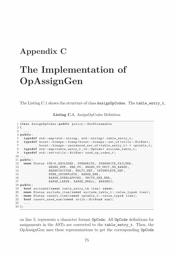
Appendix C
The Implementation of
OpAssignGen
The Listing C.1 shows the structure of class AssignOpCodes. The table_entry_t,
Listing C.1. AssignOpCodes Definition
1 c l a s s AssignOpCodes : p u b l i c policy :: OutStreamable
2 {
3 ...
4 p u b l i c :
5 typede f std::map <std::string , std::string > table_entry_t ;
6 typede f boost :: bimaps ::bimap <boost :: bimaps ::set_of <utils ::BitNum >,
7 boost :: bimaps :: unordered_set_of <table_entry_t > > optable_t;
8 typede f std::map <table_entry_t ,v2::OpCode > exclude_table_t ;
9 typede f std::set <utils ::BitNum > used_op_codes_t ;
10 ...
11 p u b l i c :
12 enum Status {OK=0,EXCLUDED , OVERWRITE , OVERWRITE_FAILURE ,
13 WRONG_NUM , ERR_FU , WRONG_FU_UNIT ,NO_RANGE ,
14 REDEFINITION , MULTI_DEF , INCOMPLETE_DEF ,
15 NONE_INCOMPLETE , RANGE_ERR ,
16 RANGE_OVERLAPPING , UNITS_GEN_ERR ,
17 RANGE_LARGE , RANGE_SMALL , ERASED };
18 p u b l i c :
19 boo l excluded( const table_entry_t & item) const ;
20 enum Status exclude_item( const exclude_table_t :: value_type& item);
21 enum Status insert_item( const optable_t :: value_type& item);
22 boo l insert_used_num ( const utils :: BitNum& num);
23 ...
24 };
on line 5, represents a character format OpCode. All OpCode definitions forassignments in the ASTs are converted to the table_entry_t. Then, theOpAssignGen uses these representations to get the corresponding OpCode
75

76 The Implementation of OpAssignGen
objects in the OperationCodes.Line 8 in Listing C.1shows the structure of table containing all excluded
OpCodes. The type of mapped value, class OpCode, is a standard represen-tation of OpCode. This class keeps both numerical and character operationcodes.
If the operation in AssignOpCodes succeeds, it returns a zero value.When an operation fails, the value in the enumeration Status on line 12 isreturned to indicates the cause of the failure.
The set, used_op_t , on line 9 contains all used OpCode values. It dosenot only includes the values assigned by users, but also the default valuesassigned automatically by the generator. Furthermore, if a range of valuesare assigned to some OpCodes, all values in that range are kept by the set,even not every value in that range is used. The main purpose for this setis to control the value space, when users want to limit the possible valuesused by OpCodes.
Listing C.2 shows the constructor of the handler. All necessary data,such as the list of operation vertices, the reference to the OperationInfo
and the current PU are passed to the handler from AssignOpCodes.
Listing C.2. AssignOpHandler Constructor
1 AssignOpHandler ( const parser ::ast:: vdesc_t& operation ,
2 arch_data ::v2:: OperationInfo & operation_info ,
3 parser :: ParseUnit& pu ,
4 boo l verbose );

Bibliography
[1] Rodolfo Azevedo. The archc architecture description language andtools. International Journal of Parallel Programming, 33:453–484, oct2005.
[2] Charles Donnelly and Richard Stallman. Bison, The Yacc-compatibleParser Generator, 2.3 edition, May 2006.
[3] Per Karlström and Wenbiao Zhou. An XML configurable design pat-tern used in NoGAP. 2010.
[4] Per A. Karlström. NoGAP: Novel Generator of Accelerators and Pro-cessors. PhD thesis, Linköping UniversityLinköping University, Com-puter Engineering, The Institute of Technology, 2010.
[5] Daniel Gajski Lukai Cai. Transaction level modeling in system leveldesign. In CECS Technical Report 03-10, 2003.
[6] Prabhat Mishra and Nikil Dutt. Architecture description languagesfor programmable embedded systems. In In IEE Proceedings on Com-puters and Digital Techniques, pages 285–297. IET, 2005.
[7] Prabhat Mishra and Nikil Dutt, editors. Processor Description Lan-guages, volume 1. Morgan Kaufmann, June 2008.
[8] Vern Paxon. Flex, A fast scanner generator.http://flex.sourceforge.net/manual/, 2.5 edition, March 1995.
[9] Stefan Pees. Modeling embedded processors and generating fast simu-lations using the machine description language lisa. TODAES, 5:815–834, oct 2002.
[10] Stefan Pees, Andreas Hoffmann, Vojin Zivojnovic, and Heinrich Meyr.LISA—machine description language for cycle-accurate models of pro-grammable DSP architectures. In DAC ’99: Proceedings of the 36th
77

78 Bibliography
annual ACM/IEEE Design Automation Conference, pages 933–938.ACM, 1999.
[11] S. Rigo, G. Araujo, M. Bartholomeu, and R. Azevedo. ArchC: ASystemC-based architecture description language. In Computer Ar-chitecture and High Performance Computing, 2004. SBAC-PAD 2004.16th Symposium on, pages 66–73, 2004.
[12] J. Siek, L. Lee, and A. Lumsdaine. Boost graph libraryhttp://www.boost.org/libs/graph acc. 070411.