binary phase of layered nanotubes - physics.nus.edu.sgphybcb/publications...350 oc for 15 min in an...
TRANSCRIPT
Binary Phase of Layered Nanotubes
R.L.D. Whitby,1 W.K. Hsu,1 C.B. Boothroyd,2 P.K. Fearon,1 H.W. Kroto1 and D.R.M. Walton1
1 School of Chemistry, Physics and Environmental Science, University of Sussex, Brighton,
BN1 9QJ, UK.2 Department of Materials Science & Metallurgy, University of Cambridge, Pembroke Street,
Cambridge, CB2 3QZ, UK.
ABSTRACT
A binary phase of layered nanotubes, where MWCNs (Multi-walled carbon nanotubes) are
coated by WS2, are generated by pyrolysing WO3-coated MWCNs in an H2S/N2 atmosphere at
900 oC. TGA and TEM show that WS2 acts as an antioxidant to the MWCN core.
INTRODUCTION
It has been demonstrated that MWCNs can act as templates for the generation of other types of
nanotubes,[1, 2] despite problems associated with their high surface tension.[3] Previous methods
for coating MWCNs with WO3 involved surface oxidation, which generated –COOH or –OH
groups[2, 4] and the MWCNs were often found uncapped and peeled.[4] Here we describe a
technique for depositing WO3 onto the surface of MWCNs and conversion to WS2 without
affecting the carbon template.
EXPERIMENT
H2WO4 (250 mg) and MWCNs (50 mg) were mixed at –78 oC in liquid NH3 (~20 cm3) and the
mixture was set aside in order to attain room temperature. The solid residue was then heated at
350 oC for 15 min in an air flow (100 cm3 min-1) to convert H2WO4 to WO3 and then further
heated at 900 oC for 15 min in a mixture of H2S and N2 (ca. 1:3 ratio, total 50 cm3 min-1) to
convert WO3 into WS2. The products were ultrasonically dispersed in acetone and mounted on
lacey carbon films (Cu support grids) for TEM analysis. The following equipment was employed
as appropriate: high-resolution transmission electron microscopy (HRTEM, JEOL 4000 EX II
operated at 400 kV, Philips CM 200 operated at 200 kV) equipped with an energy dispersive X-
ray probe and line mapping (EDX), and thermogravametric analysis (Perkin Elmer TGA-7,
heating rate of 10 K min-1).

DISCUSSION
HRTEM showed that 60 % of the MWCNs were either partly or fully coated with dark
material, typically with 1 to 3 layers (Figure 1). A number of features are distinguishable in the
HRTEM images of the sample: 1) the d-spacing of MWCN layers is maintained after the
experiment at ca. 3.4 Å; 2) the d-spacing of the dark layers is ca. 6.2 Å, consistent with separate
WS2 nanotubes; 3) the distance between the centres of the outermost C layer and the innermost
WS2 layer is ca. 4.4 Å; 4) the residual amorphous layer coating both the partly and fully coated
MWCN is WO3-x, resulting from the incomplete conversion of WO3 to WS2.
Figure 1. HRTEM image of MWCNs and polyhedral carbon particle coated with WS2.
EDX analysis was carried out on both partly and fully coated MWCNs. Only a C signal was
detected when the probe was focused on the uncoated sections of a partly coated MWCN. C, W
and S, together with a trace of O, were detected when the EDX probe was focused on the coated
section (Figure 2). Quantitative analysis showed the atomic ratio of W to S was 1:2 (± 0.1),
implying a WS2 structure.

Figure 2. EDX profile for a fully WS2-coated MWCN.
Line mapping analysis was carried out on a fully WS2-coated MWCN. The C, W and S
mappings were taken from C-Ka, W-Ma1 and S-Ka states respectively (from the EDX probing
results). The mapping profile intensity was found to be W > S > C. The width of W and S profiles
was greater than the C profile and indicates that the MWCNs are actually sheathed within WS2
tubes.
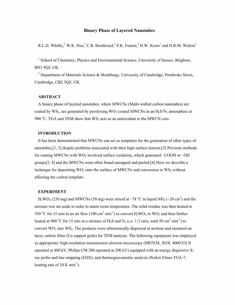
A diffractogram (Figure 3b) was derived from Fourier Transform calculations on the WS2-
coated region of Figure 3a. Two sets of diffraction spots appear in hexagonal arrays, which match
the diffraction pattern for the hexagonal WS2 structure. Two hexagonal arrays result from the
electron beam scattering by the front and rear coated sections of the MWCN, which are rotated
from each other by ca. 17 o. Therefore the WS2 nanotube is helical and inclined at ca. 8.5 o.
Above the white arrows (Figure 3a) part of the WS2 coat is extended away from the overlap of the
front and rear coating sections. Striations, inclined at 8.5 o, are observed extending from one side
of the WS2 coat to the other, which are comprised of spots separated by ca. 3.1 Å. This is
represented in Figure 3c (upper), where the spots correspond to the positions of W atoms, in
hexagonal WS2, in which they are separated by 3.153 Å (3c, lower). By enhancing the HRTEM
image (Figure 3a) by computer, the bonding structure of WS2 can be clearly observed (Figure 3d).
Figure 3a) HRTEM image of a partly WS2-coated MWCN (below white arrows), insert shows
electron diffraction pattern from a WS2-coated MWCN. b) diffractogram obtained from the lattice
image of Figure 3a showing the tube helicity to be ca. 8.5 o. c) a simulated dark spot array from
the excess of WS2 coating the rear of the tube; the W-W distance is ca. 3.1 Å. d) an enhanced
HRTEM image of WS2 coating the rear of the MWCN.
Previous reports showed that MWCNs are significantly damaged when heated at 700 –750 oC
for 30 min and lose about 99 % mass. The remaining 1 % are significantly damaged and
decapped.[5] For comparative purposes, TGA analyses were performed on MWCNs, WS2-
nanostructures and WS2-coated MWCNs. In Figure 4, the TGA curve of MWCNs (red line)

shows that the onset of oxidation begins ca. 700 oC and drastic mass loss occurs between 700 and
900 oC. At ca. 910 oC their mass loss is ca. 99 %. The TGA curve of WS2-nanostructures (green
line) exhibits a 3.4 % mass loss at ca. 530 oC. This is attributed to the conversion of WS2 into
WO3. No further mass loss is recorded towards the end of the experiment. The TGA of WS2-
coated MWCNs (blue line) shows a stepwise profile. The first mass loss is around 450 oC,
attributed to the WS2 converting to WO3. This occurs at a slightly lower temperature than
separate WS2-nanostructures, possibly due to the thinner and more defective WS2 layers coating
the MWCN allowing easier diffusion of gases between the layers. The second mass loss occurs
between 550 and 850 oC, attributed to the oxidation of MWCNs. The resulting dark-green powder
(WO3 is a light green powder, therefore the darker green colour arises from the presence of
MWCNs mixed with WO3) was subjected to TEM analysis and revealed the presence of MWCNs
that are slightly thinned and decapped (Figure 5).
Figure 4. TGA of MWCNs, WS2-nanostructures and WS2-coated MWCNs.

Figure 5. TEM image of WS2-coated MWCNs after TGA. Selected MWCNs exhibit a
reduction in the number of carbon layers towards the tip due to peeling (arrows).
CONCLUSIONS
We have demonstrated the facile way in which WO3 can be deposited onto MWCN surfaces
and converted to WS2. Interestingly, this transformation converts disordered WO3 into layered
WS2 nanotubular sheaths. Due to its composite nature, we have improved the ability of MWCNs
to withstand oxidation, which may find application as fire-retardant strengthening additives.
ACKNOWLEDGEMNTS
We thank the Leverhulme Trust, the Royal Society and the EPSRC (UK) for financial support.
We are also grateful to D. Randall and J. Thorpe (University of Sussex) for assistance with TEM
analysis and N. Billingham (University of Sussex) for TGA discussions.
REFERENCES
1. P.M. Ajayan, O. Stephan, P. Redlich, C. Colliex, Nature 1995, 375, 564.
2. B.C. Satishkumar, A. Govindaraj, M. Nath, C.N.R. Rao, J. Mater. Chem. 2000, 10, 2115.
3. E. Dujardin, T.W. Ebbesen, H. Hiura, K. Tanigaki, Science 1994, 265, 1850.
4. W.K. Hsu, Y.Q. Zhu, H.W. Kroto, D.R.M. Walton, R. Kamalakaran, M. Terrones, Appl.
Phys. Lett. 2000, 77, 4130.
5. T.W. Ebbesen, P.M. Ajayan, H. Hiura, K. Tanigaki, Nature 1994, 367, 519.