biomatic+ 50 - jsa oyfiles.ariterm.fi/pelletti/kattilat/biomatic+ 50 eng v0906_web.pdf · thanks to...
TRANSCRIPT
ARITERM SWEDEN AB Installation, Operation & Maintenance - 2009.02.18- 1/24
INSTALLATION, OPERATION AND MAINTENANCE
• Biomatic+ 50
ARITERM SWEDEN AB Installation, Operation & Maintenance - 2009.02.18- 2/24
CONTENTS
Keep this instruction manual readily available for future use.• Read the instructions carefully before taking your pellets installation into service.• The capacity of the burner is calculated according to the maximum volume of • pellets that can be fed to and burnt in the burn pot during 1 hour (based on a normal, average wood pellets quality as described in our fuel specification)Follow these instructions carefully and carry out care and maintenance work as • recommended.
Notification to building authority Attention! When you change heating installation this must always be communicated to the local building authorities.
SweepingAccording to the fire protection laws a chimney shall be swept regularly. This is done by the local chimneysweep. Sweeping of the boiler shall be carried out in such a manner that good operating economy is achieved. (see under ”Maintenance”) Prepare to chimney-sweeping by turning off the boiler at least one hour before cleaning to minimize the amount of glowing ash.
Warning! Make sure to cut the power supply to the boiler before removing the burner housing.
Maintenance contract Ariterm recommends the boiler installation to be made by a company with professio-nal competence. For more information please contact your Ariterm retailer.
Replacing of spare parts Ariterm recommends that replacing of spare parts is made by authorized serviceman of Ariterm retailer. The retailer supplies required spare parts and authorized service-man makes the necessary adjustments and combustion gas analysis when replacing spare parts.
DisposalThe metal parts of the burner and the boiler can be scrapped, the plastic parts shall be disposed of in accordance with the regulations in force.
IMPORTANT INFORMATION
Important Information .....................................................................2Dimensions / Items Included / Technical Data ............................3Operating Principle ..........................................................................4Safety and Alarms .............................................................................5Installation .........................................................................................6Water Piping ................................................................................. 6-7Filling of Water .................................................................................8Wiring Diagram ................................................................................9Start-up in OFF Mode ...................................................................10Start-up in Operating Mode .........................................................10Settings ............................................................................................11Burner Overview .............................................................................11Control Panel ..................................................................................12Control Computer and Menus ......................................................12Displayed Messages ..................................................................13-14Actions Chart ..................................................................................15Troubleshooting ........................................................................16-17Maintenance, Care, Sweeping ..................................................18-20Advice about Fuel Pellets ...............................................................21Guarantee ........................................................................................21Storage Planning .............................................................................21Feeding System .........................................................................22-24Declaration of Conformity ............................................................25Installation Protocol.... ...................................................................26Notes ...............................................................................................27
ARITERM SWEDEN AB Installation, Operation & Maintenance - 2009.02.18- 3/24
DIMENSIONS / ITEMS INCLUDED IN THE DELIVERY / TECHNICAL DATA
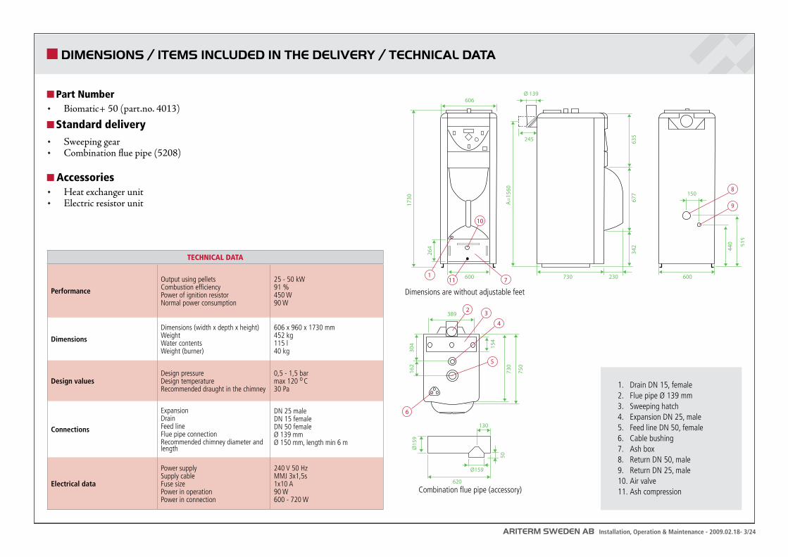
Part NumberBiomatic+ 50 (• part.no. 4013)
Standard delivery Sweeping gear• Combination flue pipe (5208)•
Accessories Heat exchanger unit• Electric resistor unit•
730600 600
245
606
1730
264
230
342 44
0 515
677
635
Ø 139
389
750
730
304
162
A=1
560
150
154
1
2
4
7
5
6
3
9
8
620
130
Ø159
Ø15
9
50
11
10
1. Drain DN 15, female2. Flue pipe Ø 139 mm3. Sweeping hatch4. Expansion DN 25, male5. Feed line DN 50, female6. Cable bushing7. Ash box8. Return DN 50, male9. Return DN 25, male10. Air valve11. Ash compression
TECHNICAL DATA
Performance
Output using pelletsCombustion efficiency Power of ignition resistor Normal power consumption
25 - 50 kW91 %450 W90 W
Dimensions
Dimensions (width x depth x height)WeightWater contentsWeight (burner)
606 x 960 x 1730 mm452 kg115 l40 kg
Design valuesDesign pressureDesign temperatureRecommended draught in the chimney
0,5 - 1,5 barmax 120 o C30 Pa
Connections
ExpansionDrainFeed lineFlue pipe connectionRecommended chimney diameter and length
DN 25 maleDN 15 femaleDN 50 femaleØ 139 mmØ 150 mm, length min 6 m
Electrical data
Power supplySupply cableFuse sizePower in operationPower in connection
240 V 50 HzMMJ 3x1,5s1x10 A90 W600 - 720 W
Dimensions are without adjustable feet
Combination flue pipe (accessory)
ARITERM SWEDEN AB Installation, Operation & Maintenance - 2009.02.18- 4/24
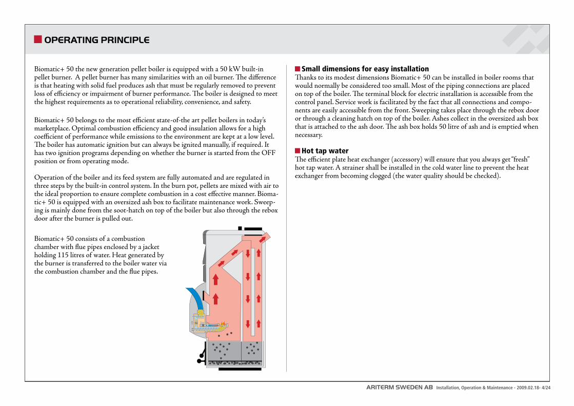
Biomatic+ 50 the new generation pellet boiler is equipped with a 50 kW built-in pellet burner. A pellet burner has many similarities with an oil burner. The difference is that heating with solid fuel produces ash that must be regularly removed to prevent loss of efficiency or impairment of burner performance. The boiler is designed to meet the highest requirements as to operational reliability, convenience, and safety.
Biomatic+ 50 belongs to the most efficient state-of-the art pellet boilers in today’s marketplace. Optimal combustion efficiency and good insulation allows for a high coefficient of performance while emissions to the environment are kept at a low level. The boiler has automatic ignition but can always be ignited manually, if required. It has two ignition programs depending on whether the burner is started from the OFF position or from operating mode.
Operation of the boiler and its feed system are fully automated and are regulated in three steps by the built-in control system. In the burn pot, pellets are mixed with air to the ideal proportion to ensure complete combustion in a cost effective manner. Bioma-tic+ 50 is equipped with an oversized ash box to facilitate maintenance work. Sweep-ing is mainly done from the soot-hatch on top of the boiler but also through the rebox door after the burner is pulled out.
Biomatic+ 50 consists of a combustion chamber with flue pipes enclosed by a jacket holding 115 litres of water. Heat generated by the burner is transferred to the boiler water via the combustion chamber and the flue pipes.
Small dimensions for easy installationThanks to its modest dimensions Biomatic+ 50 can be installed in boiler rooms that would normally be considered too small. Most of the piping connections are placed on top of the boiler. The terminal block for electric installation is accessible from the control panel. Service work is facilitated by the fact that all connections and compo-nents are easily accessible from the front. Sweeping takes place through the rebox door or through a cleaning hatch on top of the boiler. Ashes collect in the oversized ash box that is attached to the ash door. The ash box holds 50 litre of ash and is emptied when necessary.
Hot tap waterThe efficient plate heat exchanger (accessory) will ensure that you always get “fresh” hot tap water. A strainer shall be installed in the cold water line to prevent the heat exchanger from becoming clogged (the water quality should be checked).
OPERATING PRINCIPLE
ARITERM SWEDEN AB Installation, Operation & Maintenance - 2009.02.18- 5/24
SAFETY AND ALARMS
The boiler is designed according to the same main principles as an oil heated system. The advantage of this pelletsystem is easy and comfortable handling, as the location of the fuel store does not depend on the layout of the boiler room. From the safety point of view, the separation of fuel store and burner in combination with interrupted fuel supply between the two means high security.
In the event of temperature sensor failure, the high-limit thermostat stops ope-• ration to prevent the boiler from overheating. The burner automatically resumes normal operation after power failure or interrupted fuel supply. Equipment failure leading to operation stop is indicated by a red LED combined • with a message on the display panel indicating the cause of the failure. In case of fuel shortage, there is also an audible alarm. The boiler design is outstanding with safety as an integral part of the function. As • the fuel supply is interrupted and corrected in the burner auger pipe before the boiler wall, there is no continuous fuel line capable of transferring heat outside the boiler wall which means that you do not have to rely on extra safety devices.
For details about the various alarm conditions please refer to ”Troubleshooting”.
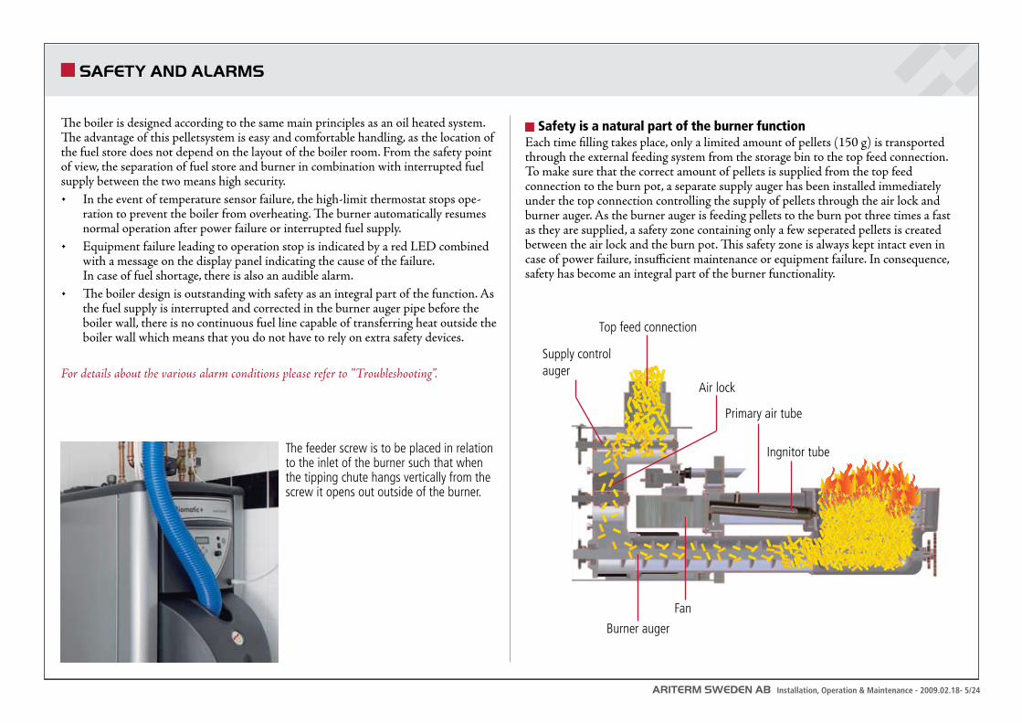
Safety is a natural part of the burner functionEach time filling takes place, only a limited amount of pellets (150 g) is transported through the external feeding system from the storage bin to the top feed connection. To make sure that the correct amount of pellets is supplied from the top feed connection to the burn pot, a separate supply auger has been installed immediately under the top connection controlling the supply of pellets through the air lock and burner auger. As the burner auger is feeding pellets to the burn pot three times a fast as they are supplied, a safety zone containing only a few seperated pellets is created between the air lock and the burn pot. This safety zone is always kept intact even in case of power failure, insufficient maintenance or equipment failure. In consequence, safety has become an integral part of the burner functionality.
The feeder screw is to be placed in relation to the inlet of the burner such that when the tipping chute hangs vertically from the screw it opens out outside of the burner.
Top feed connection
Air lock
Primary air tube
Ingnitor tube
Burner auger
Fan
Supply control auger
ARITERM SWEDEN AB Installation, Operation & Maintenance - 2009.02.18- 6/24
INSTALLATION
The boiler shall be positioned and installed according to the building rules in force. Before installing the boiler, the chimney must be controlled for underpressure and possible risk of condensation. It is possible that an air draught compensator has to be installed. Inner pipe is recommended for minimizing the risk of condensation. Space needed for installation: Minimum clearance in front of the boiler (burner included) is 1 m. Clearence by the other side of the boiler shall be at least 0,8 m. Minimum clearence on the top of the boiler shall be 0,5 m. The boiler must be level. If the floor is uneven, adjustments can be made with the help of four adjusting bolts (enclosed with the boiler) that shall be fitted to the bottom plate of the boiler. The air intake duct to the boiler room must have at least the same area as the flues.
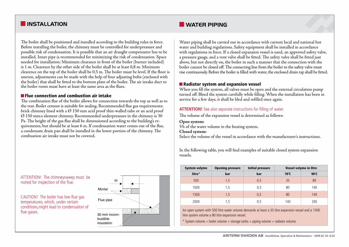
Flue connection and combustion air intakeThe combination flue of the boiler allows for connection towards the top as well as to the rear. Boiler cement is suitable for sealing. Recommended flue gas requirements: brick chimney lined with a Ø 150 mm acid proof thin-walled tube or an acid proof Ø 150 mm:s element chimney. Recommended underpressure in the chimney is 30 Pa. The height of the gas flue shall be dimensioned according to the building’s re-quirements, but should be at least 6 m. If condensation water comes out of the flue, a condensate drain pan shall be installed in the lower portion of the chimney. The combustion air intake must not be covered.
ATTENTION! The chimneysweep must be notied for inspection of the flue.
CAUTION! The boiler has low flue gas temperatures, which, under certain conditions,might lead to condensation of flue gases.
30
Mortar
Flue pipe
30 mm incom-bustibleinsulation
Imbedment into chimney
A = 1560 mm(exkl ställbarafötter)
Golv
Ø200 mm
Water piping shall be carried out in accordance with current local and national hot water and building regulations. Safety equipment shall be installed in accordance with regulations in force. If a closed expansion vessel is used, an approved safety valve, a pressure gauge, and a vent valve shall be fitted. The safety valve shall be fitted just above, but not directly on, the boiler in such a manner that the connection with the boiler cannot be closed off. The connecting line from the boiler to the safety valve must rise continuously. Before the boiler is filled with water, the enclosed drain tap shall be fitted.
Radiator system and expansion vesselWhen you fill the system, all valves must be open and the external circulation pump turned off. Bleed the system carefully while filling. When the installation has been in service for a few days, it shall be bled and refilled once again.
ATTENTION! See also separate instructions for filling of water. The volume of the expansion vessel is determined as follows:Open system: 5% of the water volume in the heating system.Closed system: Select the volume of the vessel in accordance with the manufacturer’s instructions.
In the following table, you will find examples of suitable closed system expansion vessels.
WATER PIPING
System volyme Opening pressure Initial pressure Vessel volyme in litre
litre* bar bar 70˚C 90˚C
500 1,5 0,5 35 80
1000 1,5 0,5 80 140
1500 1,5 0,5 80 140
2000 1,5 0,5 140 200
An open system with 500 litre water volume demands at least a 35 litre expansion vessel and a 1500 litre system volume a 80 litre expansion vessel.
* System volume = boiler volume + storage tanks + piping volume + radiator volume.
ARITERM SWEDEN AB Installation, Operation & Maintenance - 2009.02.18- 7/24
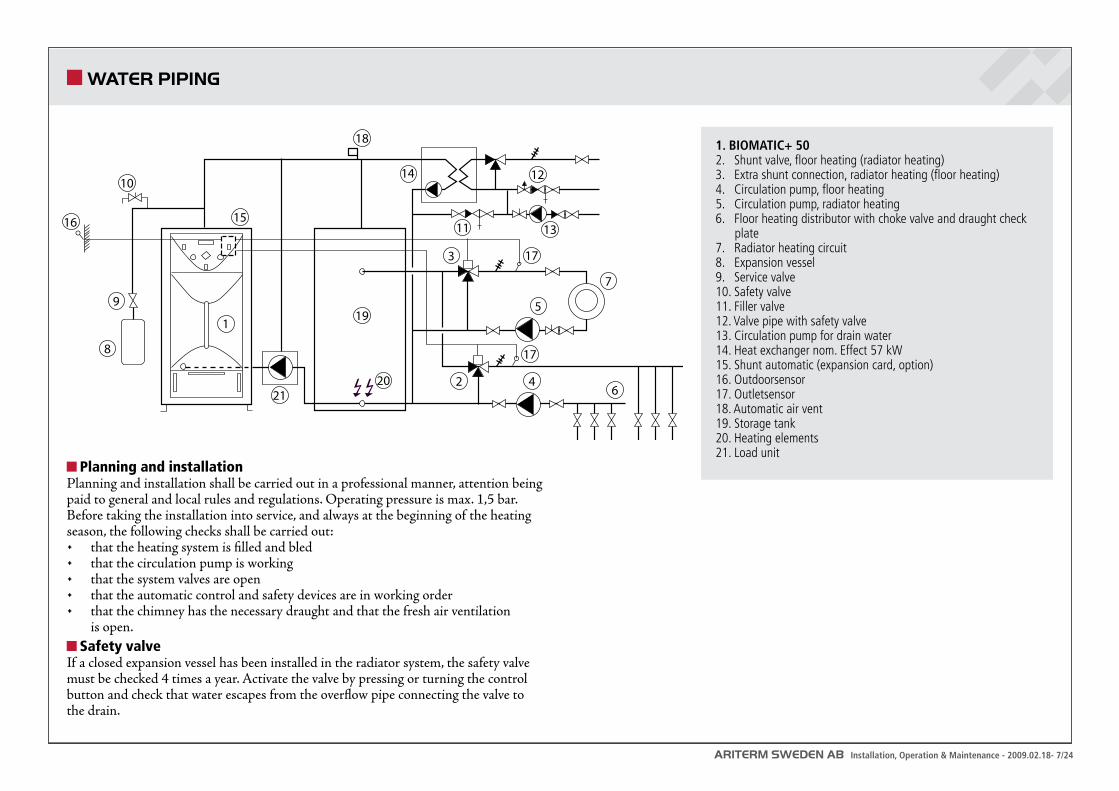
Planning and installationPlanning and installation shall be carried out in a professional manner, attention being paid to general and local rules and regulations. Operating pressure is max. 1,5 bar. Before taking the installation into service, and always at the beginning of the heating season, the following checks shall be carried out:
that the heating system is filled and bled• that the circulation pump is working• that the system valves are open• that the automatic control and safety devices are in working order• that the chimney has the necessary draught and that the fresh air ventilation • is open.
Safety valveIf a closed expansion vessel has been installed in the radiator system, the safety valve must be checked 4 times a year. Activate the valve by pressing or turning the control button and check that water escapes from the overflow pipe connecting the valve to the drain.
8
9
3
2 46
5
7
10
15
14 12
13
17
17
18 1. BIOMATIC+ 50 eller BIOMATIC 50 2. Shuntventil, golvvärme 3. Shuntventil, radiatorvärme 4. Cirkulationspump, golvvärme 5. Cirkulationspump, radiatorvärme 6. Golvvärmefördelare med stryp- och reglerventiler 7. Radiatorvärmekrets 8. Expansionskärl 9. Serviceventil10. Säkerhetsventil11. Påfyllningsventil12. Ventilrör med blandnings- och säkerhetsventil13. VVC-pump14. Värmeväxlarpaket 15. Shuntautomatik (expansionskort tillbehör)16. Utegivare17. Framledningsgivare18. Avluftning19. Ackumulatortank20. Elpatroner21. Laddpumpkoppel
2120
1116
119
1. BIOMATIC+ 502. Shunt valve, floor heating (radiator heating)3. Extra shunt connection, radiator heating (floor heating)4. Circulation pump, floor heating5. Circulation pump, radiator heating6. Floor heating distributor with choke valve and draught check plate7. Radiator heating circuit8. Expansion vessel9. Service valve10. Safety valve11. Filler valve12. Valve pipe with safety valve13. Circulation pump for drain water14. Heat exchanger nom. Effect 57 kW15. Shunt automatic (expansion card, option)16. Outdoorsensor17. Outletsensor18. Automatic air vent19. Storage tank20. Heating elements21. Load unit
WATER PIPING
ARITERM SWEDEN AB Installation, Operation & Maintenance - 2009.02.18- 8/24
Before you begin heating, the heating system must be filled with water.To fill the system, do as follows:1. Open all shut-off valves, including the shunt valve. The pump must be switched off. 2. Fill the boiler and the radiator system with water. Bleed the system at the radia-
tors. 3. Once the system is filled completely, the circulation pump can be started and
heating can begin. 4. When the boiler water has reached its pre-set operating temperature, the pump
should be stopped and the system bled at the radiators once again. This should be repeated several times.
Remember that much air is enclosed in tap water. The enclosed air volume may reach as much as 10%, which explains why bleeding takes time – especially where there are large water volumes. A closed system shall be filled until the pressure gauge indicates the correct system pressure, i.e. the distance from the pressure gauge to the highest radiator in meter times 0,1 which gives the system pressure in bar.
FILLING OF WATER
ARITERM SWEDEN AB Installation, Operation & Maintenance - 2009.02.18- 9/24
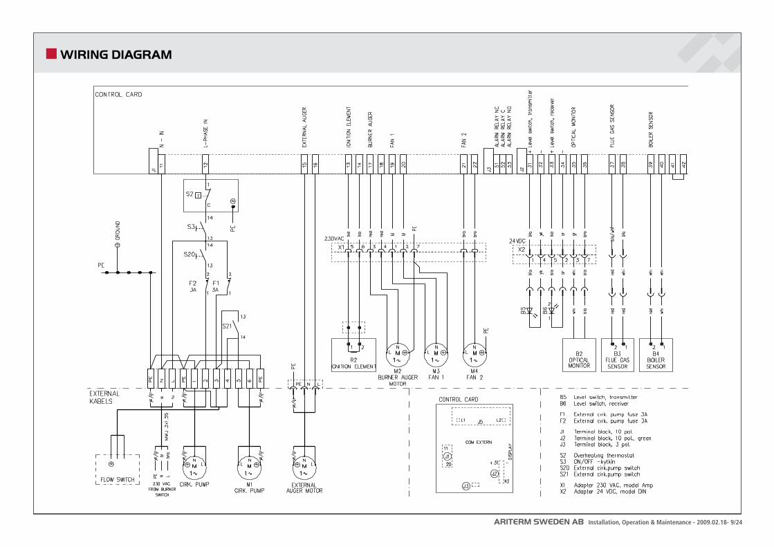
WIRING DIAGRAM
ARITERM SWEDEN AB Installation, Operation & Maintenance - 2009.02.18- 10/24
START-UP IN OFF MODE START-UP IN OPERATING MODE
Start-up in OFF mode (cold burner start with electrical ignition) You can only start up in this way when the burner has been switched off at the control panel or when the power is restored after a power cut. The boiler temperature must be 8 degrees below its set-point value.Attention! When the boiler is started for the first time after installation this must be done by an authorised installer.
If the external feed system has been emptied of pellets, it must be refilled before • you can start. The easiest way to refill the system is to remove the filling hose from the burner top coupling letting it hang freely over a container. Switch on the power to the burner control unit so that the operation indicating light is red. Operating mode shall be OFF. Scroll through menu 1 with the arrow-forward key until you reach EXTERNAL AUGER MANUAL and time (15 min). Start the external auger by pressing the plus-key. Remaining operating time is indicated on the display panel. The external auger can be stopped with the minus-key before the programmed time has elapsed.
To start the burner, scroll through menu 1 with the arrow-forward key until you • reach ON/OFF. Select ON with the pluskey. This starts the motor of the bur-ner auger feeding fuel to the burn pot. After another 3 min the fan and ignition element will become activated. When the fuel level has reached about the height of the ignition element’s hot air outlet, the feeding rate will be reduced and after a total of some 6-7 minutes the pellet fuel will ignite.
The boiler ’s optical monitor detects when the fuel has ignited and switches off the • ignition element. The red light goes out and the green comes on to confirm that the burner is operating. Fan speed is reduced. At the same time the fuel feed mo-tor stops for three minutes to allow all the pellets in the burn pot to ignite. After that pellets will be fed at reduced speed for another 5 minutes. After a subsequent wait time of 10 minutes, the burner control cuts in and controls the operation of the burner. If ignition fails, this is indicated by red light and an alarm message on the display panel.
Attention! Sometimes, when the burner is started for the first time, or if there are no pellets in the burner, a fire-start might be necessary after some 3 minutes operation. It is always possible to light the fuel manually using fire-lighting fluid.
Start and stop in operating modeThe green LED indicates that the burner is in operating mode. During operation, start and stop is regulated by the boiler temperature sensor. When the water temperature falls to 5 degrees below its set-point value, the burner starts in the programmed low power mode. If the water temperature falls by an additional 2 degrees to 7 degrees below the set-point value, the programmed high power mode is activated. The burner will then operate in this mode until the temperature has risen to 4 degrees below set-point value when it returns to low power mode. When the burner is working, the green LED is lit. A red light indicates that the burner is not in opera-tion (see ”Troubleshooting” )
OFFTo switch o the burner open menu 1 and go to ON/OFF using the arrow-forward key. Select OFF using the minus key. When the burner is switched OFF, a red light is lit on the control panel to indicate that power is connected.
Attention! Always switch off the power to the burner during service work.
ARITERM SWEDEN AB Installation, Operation & Maintenance - 2009.02.18- 11/24
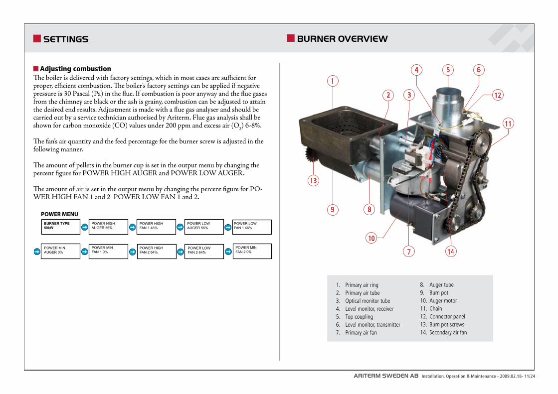
BURNER OVERVIEW
1. Primary air ring2. Primary air tube3. Optical monitor tube4. Level monitor, receiver5. Top coupling6. Level monitor, transmitter7. Primary air fan
8. Auger tube9. Burn pot10. Auger motor11. Chain12. Connector panel13. Burn pot screws14. Secondary air fan
10
1
2
5
8
4 6
12
9
7
3
11
13
14
SETTINGS
Adjusting combustion The boiler is delivered with factory settings, which in most cases are sufficient for proper, efficient combustion. The boiler’s factory settings can be applied if negative pressure is 30 Pascal (Pa) in the flue. If combustion is poor anyway and the flue gases from the chimney are black or the ash is grainy, combustion can be adjusted to attain the desired end results. Adjustment is made with a flue gas analyser and should be carried out by a service technician authorised by Ariterm. Flue gas analysis shall be shown for carbon monoxide (CO) values under 200 ppm and excess air (O2) 6-8%.
The fan’s air quantity and the feed percentage for the burner screw is adjusted in the following manner.
The amount of pellets in the burner cup is set in the output menu by changing the percent figure for POWER HIGH AUGER and POWER LOW AUGER.
The amount of air is set in the output menu by changing the percent figure for PO-WER HIGH FAN 1 and 2 POWER LOW FAN 1 and 2.
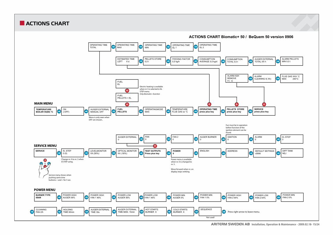
TEMPERATUREBOILER 55(80) °C
ON(-OFF)
AUGER EXTERNALMANUAL OFF
OPERATINGMODEMAX
TEMPERATUREFLUE GAS xx °C
OPERATING TIMEpress plus key
OPERATING TIMETOTAL
OPERATING TIMEMAX
OPERATING TIMEMIN
OPERATING TIMEEL 1
PELLETS STOREpress plus key
SERVICEpress plus key
ESTIMATED TIMELEFT X d
PELLETS STORE0,0 t
FEEDING FAKTOR 0,0 kg/h
CONSUMPTIONAVERAGE 0,0 kg/d
CONSUMPTIONTOTAL 0,0 t
AUGER EXTERNALTOTAL XX h
ALARM PELLETSMIN 0,0 t
ALARMCLEANING 0( Xh)
FLUE GAS XXX °CMAX 240°C
BURNER TYPE50kW
POWER HIGHAUGER 56%
POWER HIGH FAN 1 46%
POWER LOWAUGER 56%
POWER LOWFAN 1 46%
POWER MINAUGER 0%
POWER MINFAN 1 0%
SERVICE EL STEP0 (0)
LEVELMONITORXX (50%)
OPTICAL MONITORXX ( 50%)
TEST OUTPUTSPress plus key
POWER0
ENGLISH ADDRESS DEFAULT SEITINGSv0906
DIFF TANKNEJ
AUGER EXTERNAL0
FAN0
FAN 20
AUGER BURNER0
IGNITION0
ALARM0
EL STEP0
Service meny shows when pushing same time buttoms < and > for 5 sec.
MAIN MENU
SERVICE MENU
POWER MENU
Menu is only seen when OFF-set chosen..
FUELPELLETS
FUELPELLETS + EL
FUELEL
AUGER EXTERNALTIME MAN. 15min
HOT STARTSBURNER X
COLD STARTSBURNER X
SEQUENCE
Not used!
ACTIONS CHART Biomatic+ 50 / BeQuem 50 version 0906
CLEANINGFAN 2/h
HOLDINGTIME 60min
AUGER EXTERNALTIME 30s
OPERATING TIMEEL 2
POWER HIGHFAN 2 64%
POWER LOWFAN 2 64%
POWER MINFAN 2 0%
Power menu is available when nr. 0 is changed to nr. 5.
Move forward when nr. on display stops winking.
Fun must be in operation before function of the ignition element can be found.
Change nr. 0 to nr. 3 when El STEP using.
Electric heating is available when nr 3 is selected in EL STEP menu. Only Biomatic+ function
Press right arrow to leave menu.
ALARM ASH REMOVEX ( x)
ARITERM SWEDEN AB Installation, Operation & Maintenance - 2009.02.18- 12/24
CONTROL PANEL CONTROL COMPUTER AND MENUS
Default SettingsThe settings made at the factory cover most of the control system functions. Normally only the following adjustments have to be made.:
Selection of operating mode (heat source)1. Adjustment of set-point value for boiler temperature (desired temperature of 2. boiler water).Programming of desired value for reminder alarm.3.
Service LevelsThe control unit has different menu levels for the adjustment and viewing of the control system parameters. The tables on pages 15-16 will give you a detailed description of the menus shown on the control unit display panel. Normally the control unit is at menu level 1. To reach menu level 2 ”Service”, do the following:
Press arrow forward and arrow backward at the same time for 5 seconds.• The message ”Service” is shown on the display panel. The control unit is now at the service menu.Move forward in the service menu by pressing ”arrow forward” .•
If you do not press any of the control keys, the control unit will revert to menu 1automatically after 8 minutes. There are two more service levels, but they are reserved for the service technician only.
1
2
1. Display for set values2. Display of operation and active alarms with indi cation light
Green: Burner in operation Red: Alarm (burner not in operation) Flashing: Warning light (does not switch off the burner) Browsing forward in the menu Browsing backward in the menu Increases the set values Decreases the set values
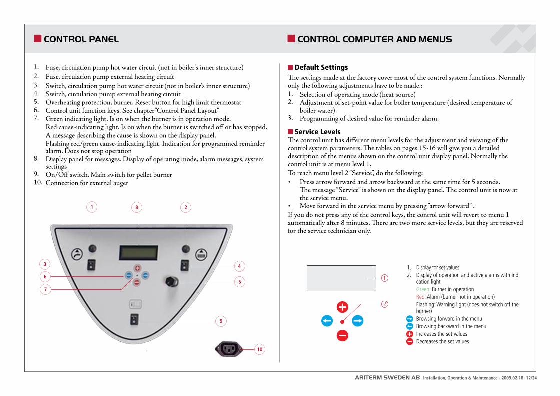
Fuse, circulation pump hot water circuit (not in boiler's inner structure)1. Fuse, circulation pump external heating circuit 2. Switch, circulation pump hot water circuit (not in boiler's inner structure) 3. Switch, circulation pump external heating circuit 4. Overheating protection, burner. Reset button for high limit thermostat 5. Control unit function keys. See chapter”Control Panel Layout” 6. Green indicating light. Is on when the burner is in operation mode. 7. Red cause-indicating light. Is on when the burner is switched off or has stopped.A message describing the cause is shown on the display panel. Flashing red/green cause-indicating light. Indication for programmed reminder alarm. Does not stop operationDisplay panel for messages. Display of operating mode, alarm messages, system 8. settings On/Off switch. Main switch for pellet burner9. Connection for external auger 10.
1 28
4
5
9
6
3
7
10
ARITERM SWEDEN AB Installation, Operation & Maintenance - 2009.02.18- 13/24
DISPLAY MESSAGES AND POSSIBLE ADJUSTMENTS
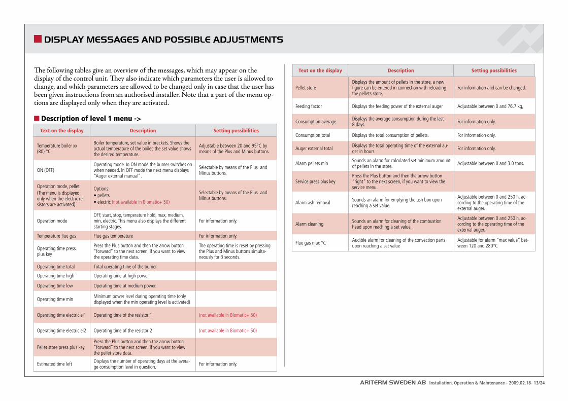
The following tables give an overview of the messages, which may appear on the display of the control unit. They also indicate which parameters the user is allowed to change, and which parameters are allowed to be changed only in case that the user has been given instructions from an authorised installer. Note that a part of the menu op-tions are displayed only when they are activated.
Description of level 1 menu ->
Text on the display Description Setting possibilities
Temperature boiler xx (80) °C
Boiler temperature, set value in brackets. Shows the actual temperature of the boiler, the set value shows the desired temperature.
Adjustable between 20 and 95°C by means of the Plus and Minus buttons.
ON (OFF)Operating mode. In ON mode the burner switches on when needed. In OFF mode the next menu displays “Auger external manual”.
Selectable by means of the Plus and Minus buttons.
Operation mode, pellet(The menu is displayed only when the electric re-sistors are activated)
Options:• pellets• electric (not available in Biomatic+ 50)
Selectable by means of the Plus and Minus buttons.
Operation modeOFF, start, stop, temperature hold, max, medium, min, electric. This menu also displays the different starting stages.
For information only.
Temperature flue gas Flue gas temperature For information only.
Operating time press plus key
Press the Plus button and then the arrow button “forward” to the next screen, if you want to view the operating time data.
The operating time is reset by pressing the Plus and Minus buttons simulta-neously for 3 seconds.
Operating time total Total operating time of the burner.
Operating time high Operating time at high power.
Operating time low Operating time at medium power.
Operating time min Minimum power level during operating time (only displayed when the min operating level is activated)
Operating time electric el1 Operating time of the resistor 1 (not available in Biomatic+ 50)
Operating time electric el2 Operating time of the resistor 2 (not available in Biomatic+ 50)
Pellet store press plus keyPress the Plus button and then the arrow button “forward” to the next screen, if you want to view the pellet store data.
Estimated time left Displays the number of operating days at the avera-ge consumption level in question. For information only.
Text on the display Description Setting possibilities
Pellet storeDisplays the amount of pellets in the store, a new figure can be entered in connection with reloading the pellets store.
For information and can be changed.
Feeding factor Displays the feeding power of the external auger Adjustable between 0 and 76.7 kg,
Consumption average Displays the average consumption during the last 8 days. For information only.
Consumption total Displays the total consumption of pellets. For information only.
Auger external total Displays the total operating time of the external au-ger in hours For information only.
Alarm pellets min Sounds an alarm for calculated set minimum amount of pellets in the store. Adjustable between 0 and 3.0 tons.
Service press plus keyPress the Plus button and then the arrow button “right” to the next screen, if you want to view the service menu.
Alarm ash removal Sounds an alarm for emptying the ash box upon reaching a set value.
Adjustable between 0 and 250 h, ac-cording to the operating time of the external auger.
Alarm cleaning Sounds an alarm for cleaning of the combustion head upon reaching a set value.
Adjustable between 0 and 250 h, ac-cording to the operating time of the external auger.
Flue gas max °C Audible alarm for cleaning of the convection parts upon reaching a set value
Adjustable for alarm “max value” bet-ween 120 and 280°C
ARITERM SWEDEN AB Installation, Operation & Maintenance - 2009.02.18- 14/24
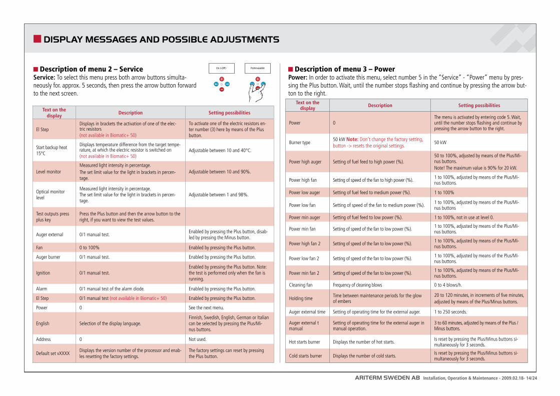
DISPLAY MESSAGES AND POSSIBLE ADJUSTMENTS
Description of menu 2 – ServiceService: To select this menu press both arrow buttons simulta-neously for. approx. 5 seconds, then press the arrow button forward to the next screen.
Text on the display Description Setting possibilities
El StepDisplays in brackets the activation of one of the elec-tric resistors(not available in Biomatic+ 50)
To activate one of the electric resistors en-ter number (3) here by means of the Plus button.
Start backup heat 15°C
Displays temperature difference from the target tempe-rature, at which the electric resistor is switched on (not available in Biomatic+ 50)
Adjustable between 10 and 40°C.
Level monitorMeasured light intensity in percentage.The set limit value for the light in brackets in percen-tage.
Adjustable between 10 and 90%.
Optical monitor level
Measured light intensity in percentage. The set limit value for the light in brackets in percen-tage.
Adjustable between 1 and 98%.
Test outputs press plus key
Press the Plus button and then the arrow button to the right, if you want to view the test values.
Auger external 0/1 manual test.Enabled by pressing the Plus button, disab-led by pressing the Minus button.
Fan 0 to 100% Enabled by pressing the Plus button.
Auger burner 0/1 manual test. Enabled by pressing the Plus button.
Ignition 0/1 manual test.Enabled by pressing the Plus button. Note: the test is performed only when the fan is running.
Alarm 0/1 manual test of the alarm diode. Enabled by pressing the Plus button.
El Step 0/1 manual test (not available in Biomatic+ 50) Enabled by pressing the Plus button.
Power 0 See the next menu.
English Selection of the display language.Finnish, Swedish, English, German or Italian can be selected by pressing the Plus/Mi-nus buttons.
Address 0 Not used.
Default set vXXXXDisplays the version number of the processor and enab-les resetting the factory settings.
The factory settings can reset by pressing the Plus button.
Description of menu 3 – PowerPower: In order to activate this menu, select number 5 in the “Service” - “Power” menu by pres-sing the Plus button. Wait, until the number stops flashing and continue by pressing the arrow but-ton to the right.
Text on the display Description Setting possibilities
Power 0The menu is activated by entering code 5. Wait, until the number stops flashing and continue by pressing the arrow button to the right.
Burner type50 kW Note: Don’t change the factory setting, button -> resets the original settings.
50 kW
Power high auger Setting of fuel feed to high power (%).50 to 100%, adjusted by means of the Plus/Mi-nus buttons.Note! The maximum value is 90% for 20 kW.
Power high fan Setting of speed of the fan to high power (%). 1 to 100%, adjusted by means of the Plus/Mi-nus buttons.
Power low auger Setting of fuel feed to medium power (%). 1 to 100%
Power low fan Setting of speed of the fan to medium power (%). 1 to 100%, adjusted by means of the Plus/Mi-nus buttons
Power min auger Setting of fuel feed to low power (%). 1 to 100%, not in use at level 0.
Power min fan Setting of speed of the fan to low power (%). 1 to 100%, adjusted by means of the Plus/Mi-nus buttons.
Power high fan 2 Setting of speed of the fan to low power (%). 1 to 100%, adjusted by means of the Plus/Mi-nus buttons.
Power low fan 2 Setting of speed of the fan to low power (%). 1 to 100%, adjusted by means of the Plus/Mi-nus buttons.
Power min fan 2 Setting of speed of the fan to low power (%). 1 to 100%, adjusted by means of the Plus/Mi-nus buttons.
Cleaning fan Frequency of cleaning blows 0 to 4 blows/h.
Holding time Time between maintenance periods for the glow of embers
20 to 120 minutes, in increments of five minutes, adjusted by means of the Plus/Minus buttons.
Auger external time Setting of operating time for the external auger. 1 to 250 seconds.
Auger external t manual
Setting of operating time for the external auger in manual operation.
3 to 60 minutes, adjusted by means of the Plus /Minus buttons.
Hot starts burner Displays the number of hot starts. Is reset by pressing the Plus/Minus buttons si-multaneously for 3 seconds.
Cold starts burner Displays the number of cold starts. Is reset by pressing the Plus/Minus buttons si-multaneously for 3 seconds.
On (-O�) Poltinsäädöt
ARITERM SWEDEN AB Installation, Operation & Maintenance - 2009.02.18- 15/24
ACTIONS CHART
TEMPERATUREBOILER 55(80) °C
ON(-OFF)
AUGER EXTERNALMANUAL OFF
OPERATINGMODEMAX
TEMPERATUREFLUE GAS xx °C
OPERATING TIMEpress plus key
OPERATING TIMETOTAL
OPERATING TIMEMAX
OPERATING TIMEMIN
OPERATING TIMEEL 1
PELLETS STOREpress plus key
SERVICEpress plus key
ESTIMATED TIMELEFT X d
PELLETS STORE0,0 t
FEEDING FAKTOR 0,0 kg/h
CONSUMPTIONAVERAGE 0,0 kg/d
CONSUMPTIONTOTAL 0,0 t
AUGER EXTERNALTOTAL XX h
ALARM PELLETSMIN 0,0 t
ALARMCLEANING 0( Xh)
FLUE GAS XXX °CMAX 240°C
BURNER TYPE50kW
POWER HIGHAUGER 56%
POWER HIGH FAN 1 46%
POWER LOWAUGER 56%
POWER LOWFAN 1 46%
POWER MINAUGER 0%
POWER MINFAN 1 0%
SERVICE EL STEP0 (0)
LEVELMONITORXX (50%)
OPTICAL MONITORXX ( 50%)
TEST OUTPUTSPress plus key
POWER0
ENGLISH ADDRESS DEFAULT SEITINGSv0906
DIFF TANKNEJ
AUGER EXTERNAL0
FAN0
FAN 20
AUGER BURNER0
IGNITION0
ALARM0
EL STEP0
Service meny shows when pushing same time buttoms < and > for 5 sec.
MAIN MENU
SERVICE MENU
POWER MENU
Menu is only seen when OFF-set chosen..
FUELPELLETS
FUELPELLETS + EL
FUELEL
AUGER EXTERNALTIME MAN. 15min
HOT STARTSBURNER X
COLD STARTSBURNER X
SEQUENCE
Not used!
ACTIONS CHART Biomatic+ 50 / BeQuem 50 version 0906
CLEANINGFAN 2/h
HOLDINGTIME 60min
AUGER EXTERNALTIME 30s
OPERATING TIMEEL 2
POWER HIGHFAN 2 64%
POWER LOWFAN 2 64%
POWER MINFAN 2 0%
Power menu is available when nr. 0 is changed to nr. 5.
Move forward when nr. on display stops winking.
Fun must be in operation before function of the ignition element can be found.
Change nr. 0 to nr. 3 when El STEP using.
Electric heating is available when nr 3 is selected in EL STEP menu. Only Biomatic+ function
Press right arrow to leave menu.
ALARM ASH REMOVEX ( x)
ARITERM SWEDEN AB Installation, Operation & Maintenance - 2009.02.18- 16/24
TROUBLESHOOTING
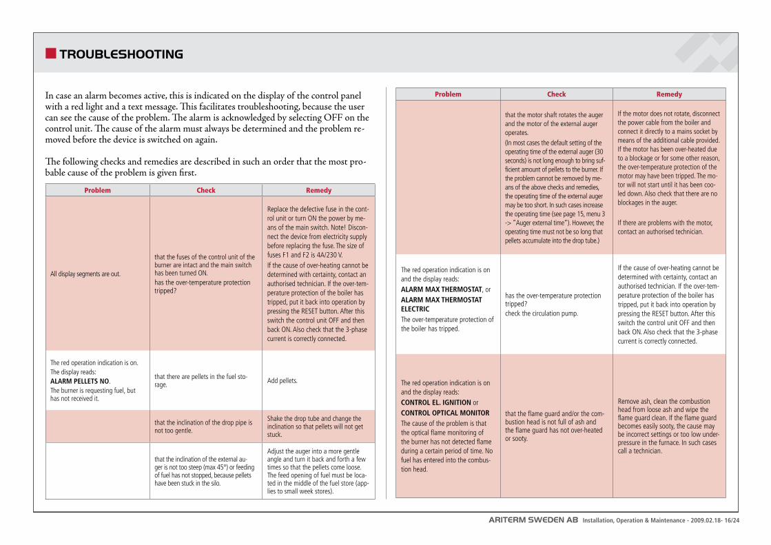
Problem Check Remedy
All display segments are out.
that the fuses of the control unit of the burner are intact and the main switch has been turned ON.has the over-temperature protection tripped?
Replace the defective fuse in the cont-rol unit or turn ON the power by me-ans of the main switch. Note! Discon-nect the device from electricity supply before replacing the fuse. The size of fuses F1 and F2 is 4A/230 V.If the cause of over-heating cannot be determined with certainty, contact an authorised technician. If the over-tem-perature protection of the boiler has tripped, put it back into operation by pressing the RESET button. After this switch the control unit OFF and then back ON. Also check that the 3-phase current is correctly connected.
The red operation indication is on.The display reads: ALARM PELLETS NO.The burner is requesting fuel, but has not received it.
that there are pellets in the fuel sto-rage. Add pellets.
that the inclination of the drop pipe is not too gentle.
Shake the drop tube and change the inclination so that pellets will not get stuck.
that the inclination of the external au-ger is not too steep (max 45°) or feeding of fuel has not stopped, because pellets have been stuck in the silo.
Adjust the auger into a more gentle angle and turn it back and forth a few times so that the pellets come loose. The feed opening of fuel must be loca-ted in the middle of the fuel store (app-lies to small week stores).
In case an alarm becomes active, this is indicated on the display of the control panel with a red light and a text message. This facilitates troubleshooting, because the user can see the cause of the problem. The alarm is acknowledged by selecting OFF on the control unit. The cause of the alarm must always be determined and the problem re-moved before the device is switched on again.
The following checks and remedies are described in such an order that the most pro-bable cause of the problem is given first.
Problem Check Remedy
that the motor shaft rotates the auger and the motor of the external auger operates.(In most cases the default setting of the operating time of the external auger (30 seconds) is not long enough to bring suf-ficient amount of pellets to the burner. If the problem cannot be removed by me-ans of the above checks and remedies, the operating time of the external auger may be too short. In such cases increase the operating time (see page 15, menu 3 -> ”Auger external time”). However, the operating time must not be so long that pellets accumulate into the drop tube.)
If the motor does not rotate, disconnect the power cable from the boiler and connect it directly to a mains socket by means of the additional cable provided. If the motor has been over-heated due to a blockage or for some other reason, the over-temperature protection of the motor may have been tripped. The mo-tor will not start until it has been coo-led down. Also check that there are no blockages in the auger.
If there are problems with the motor, contact an authorised technician.
The red operation indication is on and the display reads:ALARM MAX THERMOSTAT, orALARM MAX THERMOSTAT ELECTRICThe over-temperature protection of the boiler has tripped.
has the over-temperature protection tripped?check the circulation pump.
If the cause of over-heating cannot be determined with certainty, contact an authorised technician. If the over-tem-perature protection of the boiler has tripped, put it back into operation by pressing the RESET button. After this switch the control unit OFF and then back ON. Also check that the 3-phase current is correctly connected.
The red operation indication is on and the display reads:CONTROL EL. IGNITION orCONTROL OPTICAL MONITORThe cause of the problem is that the optical flame monitoring of the burner has not detected flame during a certain period of time. No fuel has entered into the combus-tion head.
that the flame guard and/or the com-bustion head is not full of ash and the flame guard has not over-heated or sooty.
Remove ash, clean the combustion head from loose ash and wipe the flame guard clean. If the flame guard becomes easily sooty, the cause may be incorrect settings or too low under-pressure in the furnace. In such cases call a technician.
ARITERM SWEDEN AB Installation, Operation & Maintenance - 2009.02.18- 17/24
TROUBLESHOOTING
Problem Check Remedy
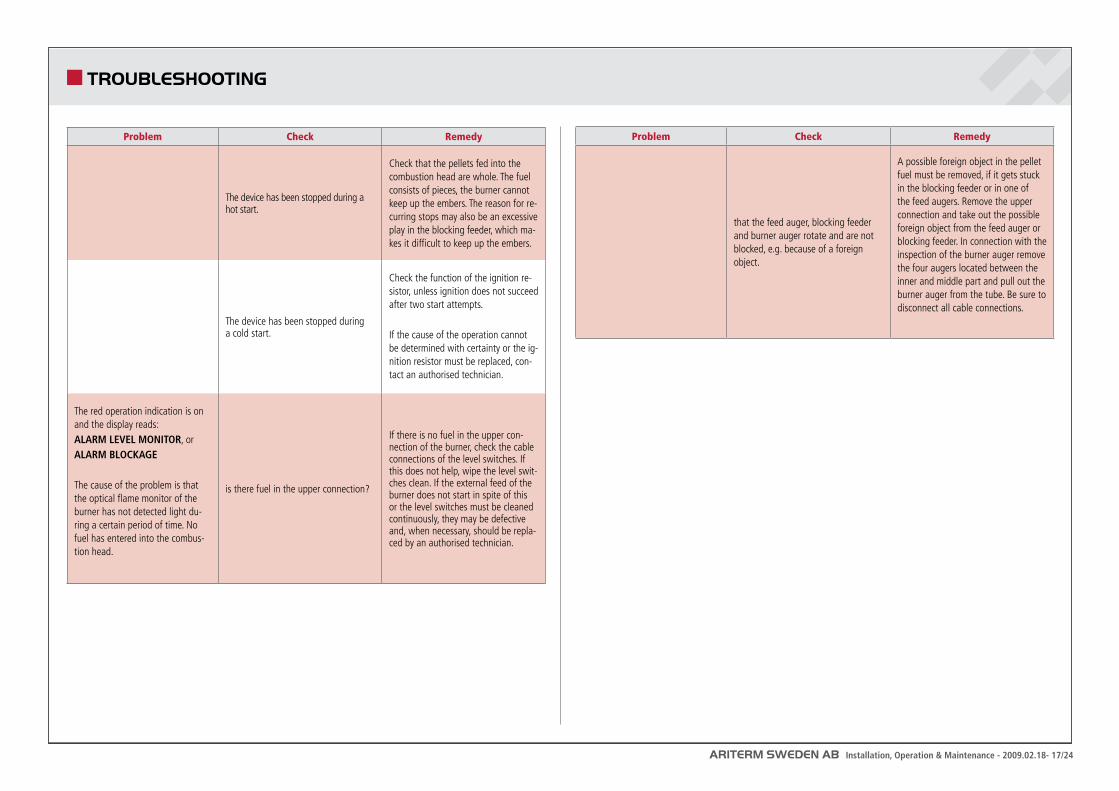
The device has been stopped during a hot start.
Check that the pellets fed into the combustion head are whole. The fuel consists of pieces, the burner cannot keep up the embers. The reason for re-curring stops may also be an excessive play in the blocking feeder, which ma-kes it difficult to keep up the embers.
The device has been stopped during a cold start.
Check the function of the ignition re-sistor, unless ignition does not succeed after two start attempts.
If the cause of the operation cannot be determined with certainty or the ig-nition resistor must be replaced, con-tact an authorised technician.
The red operation indication is on and the display reads: ALARM LEVEL MONITOR, orALARM BLOCKAGE
The cause of the problem is that the optical flame monitor of the burner has not detected light du-ring a certain period of time. No fuel has entered into the combus-tion head.
is there fuel in the upper connection?
If there is no fuel in the upper con-nection of the burner, check the cable connections of the level switches. If this does not help, wipe the level swit-ches clean. If the external feed of the burner does not start in spite of this or the level switches must be cleaned continuously, they may be defective and, when necessary, should be repla-ced by an authorised technician.
Problem Check Remedy
that the feed auger, blocking feeder and burner auger rotate and are not blocked, e.g. because of a foreign object.
A possible foreign object in the pellet fuel must be removed, if it gets stuck in the blocking feeder or in one of the feed augers. Remove the upper connection and take out the possible foreign object from the feed auger or blocking feeder. In connection with the inspection of the burner auger remove the four augers located between the inner and middle part and pull out the burner auger from the tube. Be sure to disconnect all cable connections.
ARITERM SWEDEN AB Installation, Operation & Maintenance - 2009.02.18- 18/24
Boiler cleaningBurning solid fuels, even if operation is automated, normally calls for a little more care and maintenance than oil heating. For Biomatic+ 20/30 maintenance has been mini-mized as the result of well planned design and a big ash box holding 50 litres. Ash is removed when necessary. The convection parts of the boiler are to be cleaned when the flue gas temperature has risen by 20-30˚C above the temperature of a newly swept boiler. An alarm reminding you of cleaning can be programmed on the control panel.
ATTENTION! Pay special attention to the pellets quality when you receive a new delivery or when you change supplier.
ATTENTION! Show a great care when emptying the ash as it might be glowing hot. Ash must be kept in a fireproof container.
The burner Carry out checks and measures when needed or in connection with boiler cleaning according to the following:
Normally, the burn pot does not demand any particular care, but should be • checked for carbon build-up in connection with ash removal. If necessary scrape off any carbonisation.Put the burner back into place - check carefully that no sealing is damaged. •
Once a year to once every second yearClean the primary ring and primary air tube on the inside to remove dust and • chips. Check the pins of the metering wheel, the toothed wheel and the back stop for wear. Adjust and replace if necessary. Lubricate the driving chain with a little thin oil.
When new pellet fuel is used, always check the burn pot for sintered ashes (crust of ash or gravel and stone-like particles). Such particles must be removed from the burn pot at very short intervals to prevent the primary ring from getting overheated and damaged. Sintering is caused by impurities in the pellet fuel and a claim should be sent to the supplier at once.
For more information please refer to ”Advice about Fuel Pellets”.
MAINTENANCE, CARE, SWEEPING
ARITERM SWEDEN AB Installation, Operation & Maintenance - 2009.02.18- 19/24
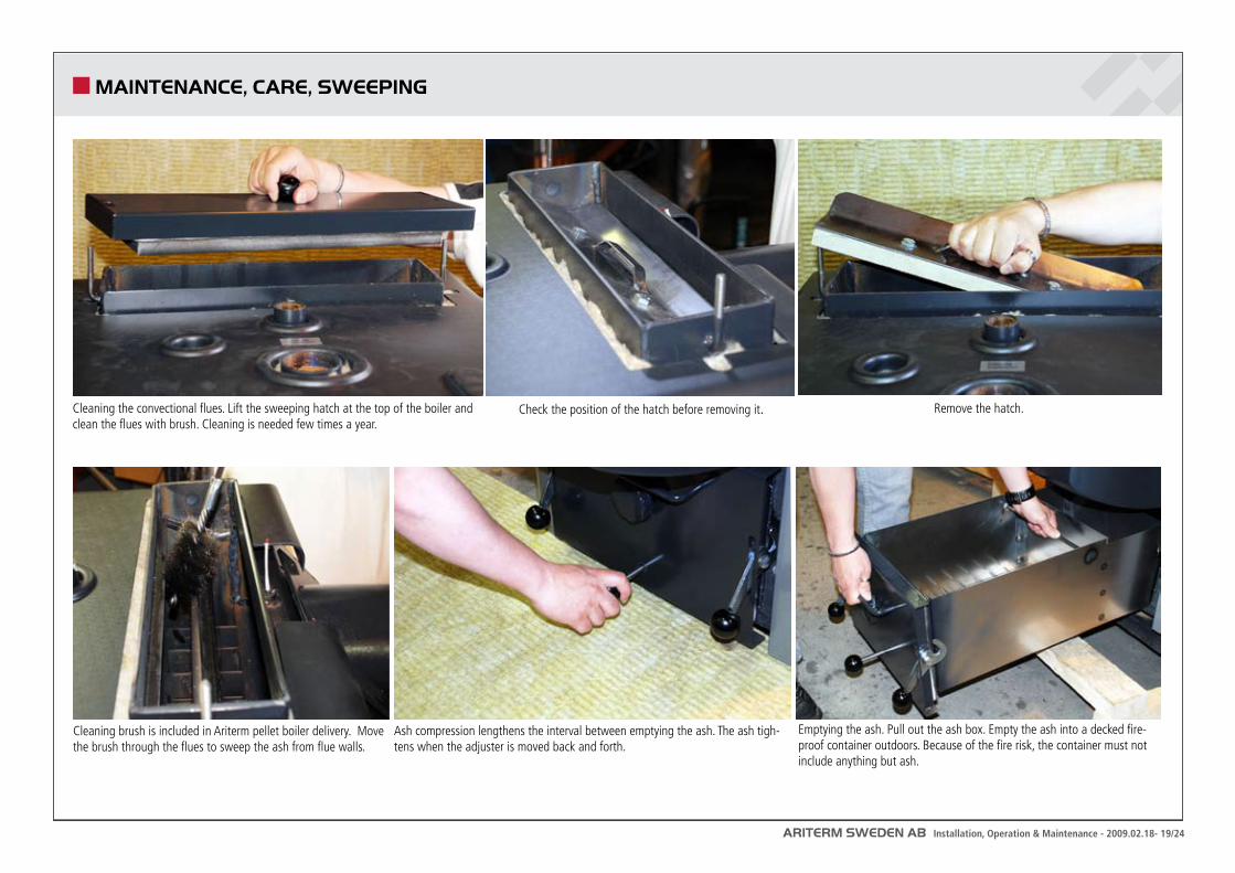
Cleaning the convectional flues. Lift the sweeping hatch at the top of the boiler and clean the flues with brush. Cleaning is needed few times a year.
Check the position of the hatch before removing it. Remove the hatch.
MAINTENANCE, CARE, SWEEPING
Cleaning brush is included in Ariterm pellet boiler delivery. Move the brush through the flues to sweep the ash from flue walls.
Ash compression lengthens the interval between emptying the ash. The ash tigh-tens when the adjuster is moved back and forth.
Emptying the ash. Pull out the ash box. Empty the ash into a decked fire-proof container outdoors. Because of the fire risk, the container must not include anything but ash.
ARITERM SWEDEN AB Installation, Operation & Maintenance - 2009.02.18- 20/24
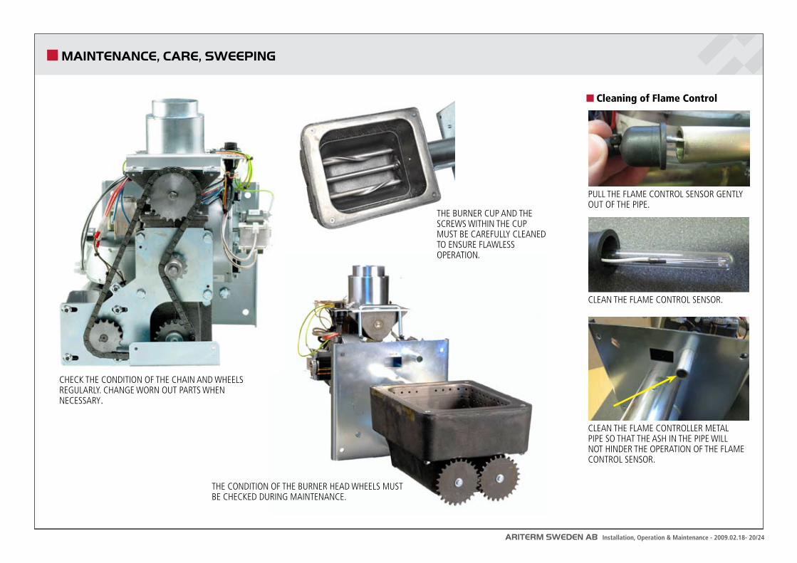
CHECK THE CONDITION OF THE CHAIN AND WHEELS REGULARLY. CHANGE WORN OUT PARTS WHEN NECESSARY.
Cleaning of Flame Control
THE CONDITION OF THE BURNER HEAD WHEELS MUST BE CHECKED DURING MAINTENANCE.
THE BURNER CUP AND THE SCREWS WITHIN THE CUP MUST BE CAREFULLY CLEANED TO ENSURE FLAWLESS OPERATION.
PULL THE FLAME CONTROL SENSOR GENTLY OUT OF THE PIPE.
CLEAN THE FLAME CONTROL SENSOR.
CLEAN THE FLAME CONTROLLER METAL PIPE SO THAT THE ASH IN THE PIPE WILL NOT HINDER THE OPERATION OF THE FLAME CONTROL SENSOR.
MAINTENANCE, CARE, SWEEPING
ARITERM SWEDEN AB Installation, Operation & Maintenance - 2009.02.18- 21/24
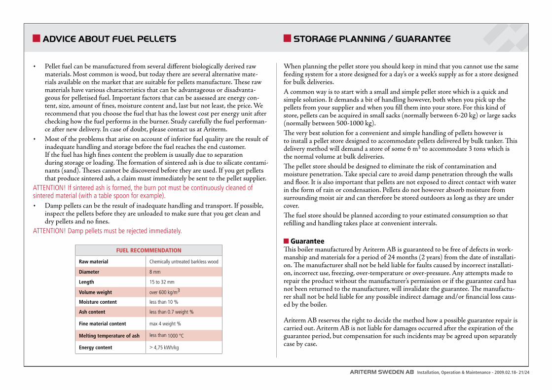
Pellet fuel can be manufactured from several different biologically derived raw • materials. Most common is wood, but today there are several alternative mate-rials available on the market that are suitable for pellets manufacture. These raw materials have various characteristics that can be advantageous or disadvanta-geous for pelletised fuel. Important factors that can be assessed are energy con-tent, size, amount of fines, moisture content and, last but not least, the price. We recommend that you choose the fuel that has the lowest cost per energy unit after checking how the fuel performs in the burner. Study carefully the fuel performan-ce after new delivery. In case of doubt, please contact us at Ariterm.Most of the problems that arise on account of inferior fuel quality are the result of • inadequate handling and storage before the fuel reaches the end customer. If the fuel has high fines content the problem is usually due to separation during storage or loading. The formation of sintered ash is due to silicate contami-nants (sand). Theses cannot be discovered before they are used. If you get pellets that produce sintered ash, a claim must immediately be sent to the pellet supplier.
ATTENTION! If sintered ash is formed, the burn pot must be continuously cleaned of sintered material (with a table spoon for example).
Damp pellets can be the result of inadequate handling and transport. If possible, • inspect the pellets before they are unloaded to make sure that you get clean and dry pellets and no fines.
ATTENTION! Damp pellets must be rejected immediately.
ADVICE ABOUT FUEL PELLETS
FUEL RECOMMENDATION
Raw material Chemically untreated barkless wood
Diameter 8 mm
Length 15 to 32 mm
Volume weight over 600 kg/m3
Moisture content less than 10 %
Ash content less than 0.7 weight %
Fine material content max 4 weight %
Melting temperature of ash less than 1000 °C
Energy content > 4,75 kWh/kg
STORAGE PLANNING / GUARANTEE
When planning the pellet store you should keep in mind that you cannot use the same feeding system for a store designed for a day’s or a week’s supply as for a store designed for bulk deliveries.A common way is to start with a small and simple pellet store which is a quick and simple solution. It demands a bit of handling however, both when you pick up the pellets from your supplier and when you fill them into your store. For this kind of store, pellets can be acquired in small sacks (normally between 6-20 kg) or large sacks (normally between 500-1000 kg). The very best solution for a convenient and simple handling of pellets however is to install a pellet store designed to accommodate pellets delivered by bulk tanker. This delivery method will demand a store of some 6 m3 to accommodate 3 tons which is the normal volume at bulk deliveries.The pellet store should be designed to eliminate the risk of contamination and moisture penetration. Take special care to avoid damp penetration through the walls and floor. It is also important that pellets are not exposed to direct contact with water in the form of rain or condensation. Pellets do not however absorb moisture from surrounding moist air and can therefore be stored outdoors as long as they are under cover. The fuel store should be planned according to your estimated consumption so that refilling and handling takes place at convenient intervals.
GuaranteeThis boiler manufactured by Ariterm AB is guaranteed to be free of defects in work-manship and materials for a period of 24 months (2 years) from the date of installati-on. The manufacturer shall not be held liable for faults caused by incorrect installati-on, incorrect use, freezing, over-temperature or over-pressure. Any attempts made to repair the product without the manufacturer’s permission or if the guarantee card has not been returned to the manufacturer, will invalidate the guarantee. The manufactu-rer shall not be held liable for any possible indirect damage and/or financial loss caus-ed by the boiler.
Ariterm AB reserves the right to decide the method how a possible guarantee repair is carried out. Ariterm AB is not liable for damages occurred after the expiration of the guarantee period, but compensation for such incidents may be agreed upon separately case by case.
ARITERM SWEDEN AB Installation, Operation & Maintenance - 2009.02.18- 22/24
FEEDING SYSTEM DEPO / FEEDO
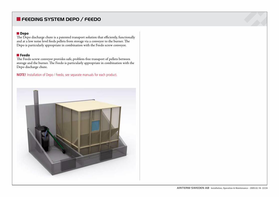
DepoThe Depo discharge chute is a patented transport solution that efficiently, functionally and at a low noise level feeds pellets from storage via a conveyor to the burner. The Depo is particularly appropriate in combination with the Feedo screw conveyor.
FeedoThe Feedo screw conveyor provides safe, problem-free transport of pellets between storage and the burner. The Feedo is particularly appropriate in combination with the Depo discharge chute.
NOTE! Installation of Depo / Feedo, see separate manuals for each product.
ARITERM SWEDEN AB Installation, Operation & Maintenance - 2009.02.18- 23/24
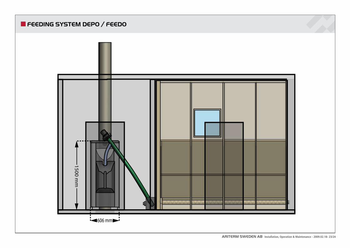
FEEDING SYSTEM DEPO / FEEDO
606 mm
1500 mm
ARITERM SWEDEN AB Installation, Operation & Maintenance - 2009.02.18- 24/24
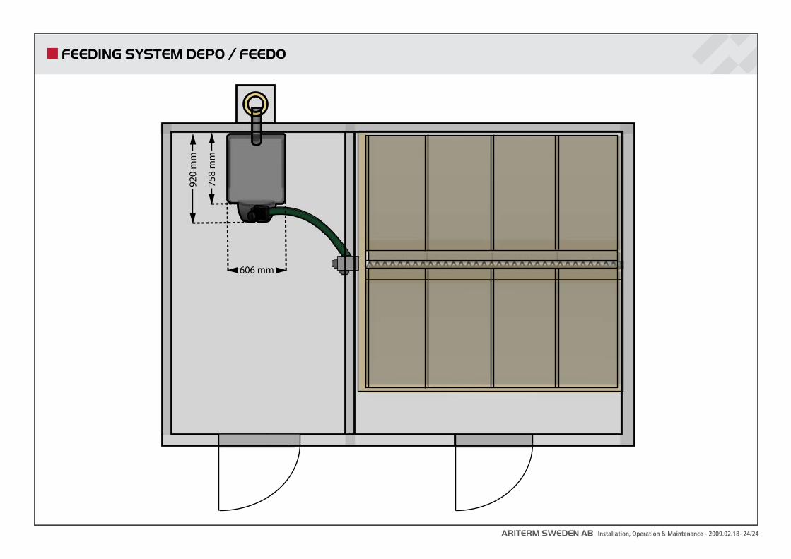
FEEDING SYSTEM DEPO / FEEDO
606 mm
758
mm
920
mm
ARITERM SWEDEN AB Installation, Operation & Maintenance - 2009.02.18- 25/24
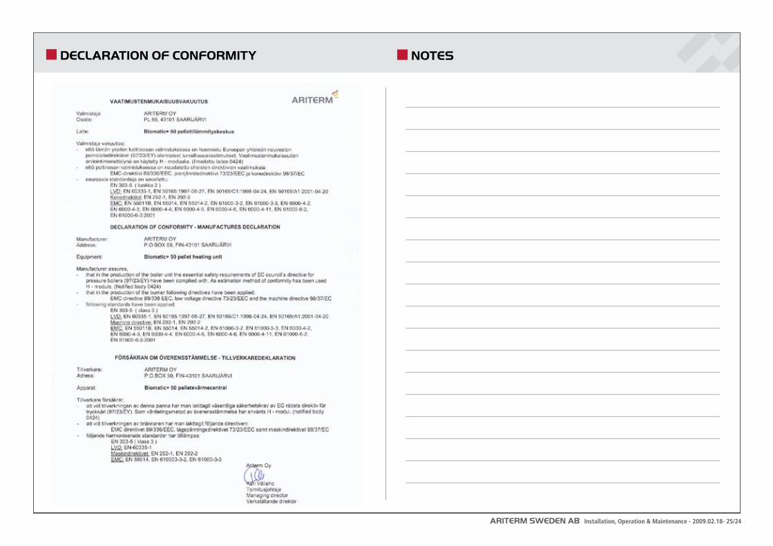
DECLARATION OF CONFORMITY NOTES
ARITERM SWEDEN AB Installation, Operation & Maintenance - 2009.02.18- 26/24
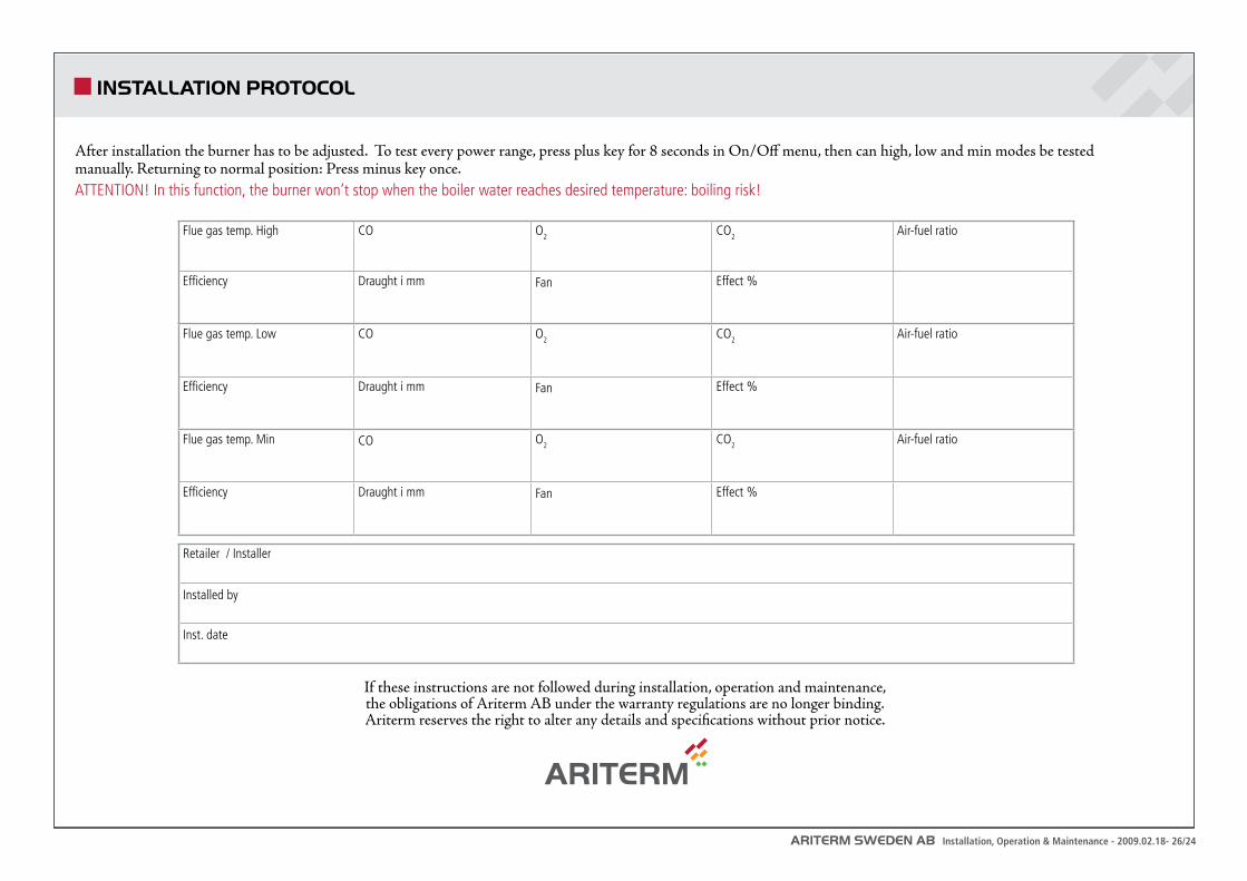
INSTALLATION PROTOCOL
After installation the burner has to be adjusted. To test every power range, press plus key for 8 seconds in On/Off menu, then can high, low and min modes be tested manually. Returning to normal position: Press minus key once.ATTENTION! In this function, the burner won’t stop when the boiler water reaches desired temperature: boiling risk!
If these instructions are not followed during installation, operation and maintenance, the obligations of Ariterm AB under the warranty regulations are no longer binding. Ariterm reserves the right to alter any details and specifications without prior notice.
Flue gas temp. High CO O2 CO2 Air-fuel ratio
Efficiency Draught i mm Fan Effect %
Flue gas temp. Low CO O2 CO2 Air-fuel ratio
Efficiency Draught i mm Fan Effect %
Flue gas temp. Min CO O2 CO2 Air-fuel ratio
Efficiency Draught i mm Fan Effect %
Retailer / Installer
Installed by
Inst. date
ARITERM SWEDEN AB Installation, Operation & Maintenance - 2009.02.18- 27/24
NOTES

ARITERM SWEDEN AB Installation, Operation & Maintenance - 2009.02.18- 28/24
Ariterm Sweden AB | Flottilvägen 15 39241 Kalmar Sweden www.ariterm.se | +46 480 442850