biomonitor iii technical manual
TRANSCRIPT

BIOMONITOR III Technical Manual

© 2020 BIOTRONIK, Inc., All rights reserved.
CAUTIONFederal (U.S.A.) law restricts this device to sale by, or on the order of, a physician. (or properly
licensed practitioner).
BIOMONITOR IIIInsertable Monitor
BIOMONITOR IIIX-Ray identification
Radiopaque IdentificationA radiopaque identification code is visible on standard X-ray, and identifies the insertable monitor:
BIOMONITOR IIITechnical Manual
BIOMONITOR III

BIOMONITOR III Technical Manual
Contents
Chapter 1: Device Description 1
Chapter 2: Indications 3
Chapter 3: Contraindications 5
Chapter 4: Warnings and Precautions 7
4.1 MRI SAFETY INFORMATION 74.1.1 Patient Pre-MRI Conditions 7
4.1.2 MRI Scanner Limitations 7
4.1.3 Restrictions during the MR Scan 8
4.2 Implanted Pacemakers and Defibrillators 8
4.3 Medical Therapy 8
4.4 Storage and Handling 9
4.5 Home Monitoring 10
4.6 Electromagnetic Interference (EMI) 104.6.1 Home and Occupational Environments 10
4.6.2 Cellular Phones 11
4.6.3 Hospital and Medical Environments 12
4.7 Insertable Cardiac Monitor Explant and Disposal 12
Chapter 5: Programmable Parameters 13
5.1 Parameters 135.1.1 ProgramConsult 13
5.1.2 Atrial Fibrillation (AF) 15
5.1.3 High Ventricular Rate (HVR) 19
5.1.4 Bradycardia 20
5.1.5 Sudden Rate Drop (SRD) 21
5.1.6 Asystole Duration 22
5.1.7 Patient Trigger 22
5.1.8 Resting Rate Period 23

BIOMONITOR III Technical Manual
5.2 Home Monitoring (HM) 235.2.1 HM PID 23
5.2.2 Home Monitoring 23
5.2.3 Time of Transmission 23
5.2.4 Periodic Subcutaneous Electrocardiogram (sECG) 24
5.2.5 Last Message 24
5.2.6 Episode Recording/Transmission 25
5.3 Patient Data 255.3.1 ID 25
5.3.2 First / Last Name 25
5.3.3 Date of Birth 26
5.3.4 Gender 26
5.3.5 Date of Implant 26
5.3.6 Hospital, City 26
5.3.7 Physician 26
5.3.8 NYHA 26
5.3.9 Symptom 27
5.3.10 Etiology 27
5.3.11 Remark 27
5.4 Sensitivity Settings 285.4.1 SensingConsult 28
5.4.2 Sensing High Pass Filter 29
5.4.3 Input Signal Polarity 30
5.4.4 Input High-Pass Filter 30
Chapter 6: Diagnostics 31
6.1 Diagnostics Overview 31
6.2 General Statistical Information 31
6.3 Activity 316.3.1 Rate Trends 32
6.3.2 Rate Histogram 32
6.3.3 Activity Trend 33
6.4 AF Details 336.4.1 AF Trends 33
6.4.2 AF Time of Occurrence 34
6.4.3 AF Duration 34
6.4.4 Ventricular Rate During AF 35

BIOMONITOR III Technical Manual
6.5 Sensing 356.5.1 R-wave Trend 35
6.5.2 Noise Duration Trend 36
Chapter 7: Other Functions/Features 37
7.1 Home Monitoring 37
7.2 Transmission of Information 37
7.3 Patient Data 37
7.4 Transmitting Data 37
7.5 Types of Report Transmissions 38
7.6 Description of Transmitted Data 38
7.7 Patient Data Memory 39
7.8 Position Indicator 40
Chapter 8: Product Storage and Handling 41
8.1 Sterilization and Storage 41
Chapter 9: Follow-up Procedures 43
9.1 General Considerations 43
9.2 Real-time sECG Transmission 43
9.3 Follow-up Page 43
9.4 Recordings 44
9.5 sECG 449.5.1 Atrial Fibrillation 45
9.5.2 High Ventricular Rate 45
9.5.3 Bradycardia 46
9.5.4 Asystole 46
9.5.5 Patient Trigger 46
Chapter 10: Elective Replacement Indication (ERI) 47
Chapter 11: Insertion/Removal 49
11.1 Opening the Sterile Container 49

BIOMONITOR III Technical Manual
11.2 Insertion 49
11.3 Removal 52
11.4 Reasons to Remove an Insertable Monitor 52
Chapter 12: Remote Assistant III 53
12.1 General Information on the Remote Assistant III 53
12.2 Remote Assistant III Functional Testing 53
12.3 Getting to Know the Remote Assistant III 53
12.4 Triggering a Manual Recording 54
12.5 Battery LED Indicator Explained 54
12.6 Signal Transmission LED Explained 54
Chapter 13: Technical Data 55
13.1 Parameters 5513.1.1 Atrial Fibrillation 55
13.1.2 High Ventricular Rate 55
13.1.3 Bradycardia 55
13.1.4 Sudden Rate Drop (SRD) 56
13.1.5 Asystole Duration 56
13.1.6 Patient Trigger 56
13.1.7 Resting Rate Period 56
13.1.8 Home Monitoring 57
13.2 Materials in Contact with Human Tissue 57
13.3 Electrical Data/Battery 57
13.4 Mechanical Data 57
Chapter 14: AF Detection Study Results 59
14.1 BioMonitor 2 Pilot Study Results 59
14.2 BioInsight Study Results 60
Chapter 15: Order Information 61

Chapter 1BIOMONITOR III Technical Manual
1
Chapter 1: Device Description
BIOMONITOR III is a programmable, subcutaneous insertable monitor able to record subcutaneous ECGs (sECGs) and other physiological parameters.The BIOMONITOR III is designed to automatically record the occurrence of arrhythmias in a patient. Arrhythmia may be classified as atrial fibrillation (AF), bradyarrhythmia, asystole, sudden rate drop, or high ventricular rate. In addition, the BIOMONITOR III can be activated by the patient to record cardiac rhythm during symptomatic episodes.The BIOMONITOR III system consists of three main components:
1. BIOMONITOR III insertable cardiac monitor - The BIOMONITOR III is a small, leadless device that is typically inserted under the skin, in the chest. The device uses two electrodes on the body of the device to continuously monitor the patient’s subcutaneous ECG. The device memory can store up to 30 min of subcutaneous ECG (sECG) recordings from automatically detected arrhythmias and up to 30 min of sECG recordings from patient-triggered episodes. When a patient experiences symptoms, the sECG recordings can be manually triggered by placing the Remote Assistant III over the BIOMONITOR III. The insertable monitor is provided preloaded in an insertion tool. An incision tool is also provided.
Note - The BIOMONITOR III subcutaneous ECG may differ from a surface ECG due to differences in electrode separation and device placement in the body.BIOMONITOR III detects a subcutaneous ECG from a pair of electrodes. These signals are filtered in two different ways. For detection of QRS complexes, the signals are filtered with a passband of 10-40 Hz in order to suppress T-waves, artifacts, and baseline drift at low frequencies, and myoptentials and EMI at high frequencies. The resulting signal is appropriate for QRS detection as other components of the signal have been suppressed. This signal naturally does not have a typical ECG morphology due to the bandpass. For waveform display (real-time streaming sECG with the physician’s programmer and snapshots for review by the physician), a different passband is utilized to retain signal features that may have diagnostic value. This passband is 0.5 – 40 Hz, which is designed to retain morphological features of a typical ECG while still rejecting large low frequency artifacts and baseline drift.
2. BIOTRONIK Renamic / ICS 3000 Programmer – The programmer is used to set up the BIOMONITOR III to detect arrhythmias. It also allows you to view, save, or print the stored information.
3. BIOTRONIK CardioMessenger® Smart is a telemetry patient device that forwards the data from the BIOMONITOR III to BIOTRONIK’s Home Monitoring Service Center.
BIOMONITOR III may be used with BIOTRONIK Home Monitoring® technology, which is an automatic, wireless, remote monitoring system for management of patients with insertable cardiac monitors. When active, Home Monitoring enables the exchange of information about a patient’s cardiac status from the implant. The information is transmitted to the Home Monitoring Service Center (HMSC), where the physician may log in to review. The HMSC can be used to provide the physician with advanced reports from the implanted device and process them into a graphical and tabular format

Chapter 1BIOMONITOR III Technical Manual
2
that is accessible via the internet platform HMSC. This information may help the physician optimize the therapy process, possibly providing earlier notification of clinically relevant events to help guide future therapy.BIOTRONIK conducted the TRUST study to evaluate the safety and effectiveness of Home Monitoring. With the TRUST study, BIOTRONIK was able to show the following with regards to Home Monitoring:
• BIOTRONIK Home Monitoring information may be used as a replacement for device interrogation during in-office follow-up visits.
• A strategy of care using BIOTRONIK Home Monitoring with office visits when needed has been shown to extend the time between routine, scheduled in-office follow-ups of BIOTRONIK implantable devices in many patients. Home Monitoring data is helpful in determining the need for additional in-office follow-up.
• BIOTRONIK Home Monitoring provides early detection of arrhythmias.• BIOTRONIK Home Monitoring provides early detection of silent, asymptomatic
arrhythmias.• Automatic early detection of arrhythmias and device system anomalies by BIOTRONIK
Home Monitoring allows for earlier intervention than conventional in-office follow-ups.• BIOTRONIK Home Monitoring allows for improved access to patient device data
compared to conventional in-office follow-ups since device data is automatically collected and reported on a daily basis.
The implanted device’s Home Monitoring function can be used for the entire operational life of the implanted device (prior to ERI). NOTE: When ERI mode is reached, this status is transmitted and Home Monitoring® will be discontinued after two weeks.
Chapter 2BIOMONITOR III Technical Manual
3
Chapter 2: Indications
The BIOMONITOR III is indicated to detect the following cardiac arrhythmias:• atrial fibrillation• bradycardia• sudden rate drop• high ventricular rate (HVR)• asystole
The BIOMONITOR III is indicated for use in:• Patients with clinical syndromes or situations at increased risk of cardiac arrhythmias• Patients who experience transient symptoms that may suggest a cardiac arrhythmia
The device has not been tested for and it is not intended for pediatric use

Chapter 2BIOMONITOR III Technical Manual
4
This page left intentionally blank

Chapter 3BIOMONITOR III Technical Manual
5
Chapter 3: Contraindications
There are no known contraindications for the insertion of the BIOMONITOR III. However, the patient’s particular physical or medical condition may dictate whether or not a subcutaneous, chronically inserted device can be tolerated.

Chapter 3BIOMONITOR III Technical Manual
6
This page left intentionally blank

Chapter 4BIOMONITOR III Technical Manual
7
Chapter 4: Warnings and Precautions
Consult the technical manuals for information about other devices used with the BIOMONITOR III, including the CardioMessenger Smart or Renamic Programmer, and related accessories.Please keep technical manuals for later use. Certain therapeutic and diagnostic procedures may cause undetected damage to an insertable cardiac monitor (ICM), resulting in malfunction or failure at a later time. Please note the following warnings and precautions:
MR Conditional - The cardiac monitor is labeled and certified MR conditional.
4.1 MRI SAFETY INFORMATION
Conditions for an MRI scan are provided below. Failure to adhere to to provided patient position or scan time limitations may result in excessive tissue warming during an MR scan.Cardiac data recorded by the implanted device during an MR scan may include artifacts that are due to the MR scan and not the patient’s cardiac function. Exercise care when interpreting any such data.
4.1.1 Patient Pre-MRI ConditionsThe following requirements must always be fulfilled in order to perform an MR scan using BIOTRONIK’s BIOMONITOR III:
• There are no other active or abandoned cardiac implants (e.g., lead extensions, lead adapters or abandoned leads) in the patient’s body.
• Other active or passive implants are permitted if they are identified as MR conditional by the manufacturer.
NOTE: An MRI scan is permitted only if the product-specific conditions are met for all implants and if no metal implantable device longer than 5 cm is in the vicinity of the BIOTRONIK cardiac monitor within a distance of less than 4 cm.
• The device is located in the patient’s chest area.
4.1.2 MRI Scanner LimitationsThe MRI scanner has to meet the following conditions:
• Use of a clinical MRI system with a cylindrical bore and a static magnetic field strength of:
ο 1.5 Tesla or 3.0 Tesla • The slew rate of the MRI scanner’s gradient fields should not exceed
200 T/m/s per axis.• Use of local transmit coils is permitted when used for the head or extremities. Local
receive coils can be used without restriction.
Chapter 4BIOMONITOR III Technical Manual
8
• Only local receiver coils may be used for the thorax.• Maximum spatial gradient of the static magnetic field specification must be ≤ 100T/m
(10,000 gauss/cm).• Under worst case conditions, the BIOMONITOR III is expected to produce a maximum
temperature rise of <4.5° C after 30 minutes of continuous scanning.• Image artifact and distortion can result from the presence of the BIOMONITOR III
device within the field of view. Image artifact and distortion resulting from the presence of the device within the field of view must be considered when selecting the field of view and imaging parameters. These factors must also be considered when interpreting the MRI images.
4.1.3 Restrictions during the MR ScanThe following conditions must be met during the MR scan:
• The mean specific absorption rate (SAR) for the whole body as displayed by the MRI scanner must not exceed 4.0 W/kg.
• The head absorption rate displayed by the MR scanner must not exceed 3.2 W/kg.
4.2 Implanted Pacemakers and Defibrillators
The BIOMONITOR III is not intended for use in patients with an implanted pacemaker or defibrillator. If the patient has a co-implanted pacemaker or defibrillator, the automatic detection of arrhythmic episodes in the BIOMONITOR III may be affected by the paced heart rhythm.
4.3 Medical Therapy
Before applying one of the following procedures, a detailed analysis of the advantages and risks should be made. Following the procedures, insertable cardiac monitor function must be checked.Therapeutic Diathermy Equipment - Use of therapeutic diathermy equipment is to be avoided for insertable cardiac monitor patients due to possible heating effects of the insertable cardiac monitor and at the implant site. If diathermy therapy must be used, it should not be applied in the immediate vicinity of the insertable cardiac monitor.Transcutaneous Electrical Nerve Stimulation (TENS) - Transcutaneous electrical nerve stimulation may interfere with insertable cardiac monitor function and is therefore not recommended. If necessary, the following measures may reduce the possibility of interference:
• Place the TENS electrodes as close to each other as possible.• Place the TENS electrodes as far from the insertable cardiac monitor as possible.
Defibrillation - The following precautions are recommended to minimize the inherent risk of insertable cardiac monitor operation being adversely affected by defibrillation:
• The paddles should not be placed directly over the implant.• The paddles should be placed anterior-posterior or along a line perpendicular to the
axis formed by the insertable cardiac monitor.

Chapter 4BIOMONITOR III Technical Manual
9
• The energy setting should not be higher than required to achieve defibrillation.• After defibrillation, evaluate the BIOMONITOR III for proper function.
Radiation - Insertable cardiac monitor electronics may be damaged by exposure to radiation during radiotherapy. To minimize this risk when using such therapy, the insertable cardiac monitor should be protected with local radiation shielding.Lithotripsy - Lithotripsy treatment should be avoided for insertable cardiac monitor patients since electrical and/or mechanical interference with the insertable cardiac monitor is possible. If this procedure must be used, the greatest possible distance from the point of electrical and mechanical strain should be chosen (25 cm minimum) in order to minimize a potential interference with the insertable cardiac monitor.Ablation/Electrocautery - Position the grounding pad so that the current path does not pass through or near the device. When possible, a bipolar electrocautery system should be used. After ablation or electrocautery, evaluate the BIOMONITOR III for proper function.Transurethral resection of the prostate - It is recommended that the cautery ground plate be placed under the buttocks or around the thigh, but not in the thoracic area where the current pathway could pass through or near the cardiac monitor.Hyperbaric Oxygen Therapy (HBOT) - Hyperbaric oxygen therapy (HBOT) for patients with BIOTRONIK CRM devices is not recommended due to the potential for damage or impaired function of the implant after exposure. The physician should conduct a risk-benefit analysis if HBOT treatment is necessary. The device specified in this manual has been tested to be in compliance with ISO 14708-2:2012, where the device is exposed to 40 cycles of ambient pressure up to 450 kPa (4.5 bar).Therapeutic Ultrasound - The BIOMONITOR III should not be exposed to therapeutic levels of ultrasound energy, as the active implantable medical device can inadvertently concentrate the ultrasound field and cause harm.
4.4 Storage and Handling
Failure to adhere to storage and handling recommendations may result in device damage or malfunction.Storage (temperature) - Recommended storage temperature range is -10° to 45°C (14°-113°F). Exposure to temperatures outside this range may result in insertable cardiac monitor malfunction (see Section 8.1).Handling - Do not drop. The monitor is preloaded into the insertion tool. If the tool is dropped onto a hard surface, return it to BIOTRONIK (see Section 8.1).FOR SINGLE USE ONLY - Do not resterilize the insertable cardiac monitor, incision tool or insertion tool; they are intended for one-time use.Device Packaging - Do not use the device if the packaging is wet, punctured, opened or damaged because the integrity of the sterile packaging may be compromised. Return the device to BIOTRONIK.Storage - Store the device in a clean area, away from sources of disturbance to avoid damage to the device.Temperature Stabilization - Allow the device to reach room temperature before programming or implanting the device. Temperature extremes may affect the initial device function.Use Before Date - Do not implant the device after the USE BEFORE DATE because the device sterility and longevity may be compromised.

Chapter 4BIOMONITOR III Technical Manual
10
Sharp - Packaging includes an incision tool that is sharp and should be handled with care.
4.5 Home Monitoring
All BIOMONITOR III devices can be used with BIOTRONIK’s Home Monitoring® system. The Home Monitoring system enables wireless automatic transmission of information about a patient’s cardiac status from the implanted device to the physician remotely.
Programming OverviewBIOTRONIK’s Home Monitoring system is designed to notify clinicians in less than 24 hours of changes to the patient’s condition or status of the implanted device. Updated data may not be available if:
• The patient’s CardioMessenger® is unplugged or damaged and is not able to connect to the Home Monitoring system through an active telephone link or cellular network.
• The CardioMessenger cannot establish a connection to the implanted device.• The telephone or cellular network is not operational or the patient lives in a
geographical area not covered by landline or cellular networks.• The Home Monitoring Service Center is off-line (upgrades are typically completed in
less than 24 hours).Patient’s Ability - Use of the Home Monitoring system requires the patient and/or caregiver to follow the system instructions and cooperate fully when transmitting data.If the patient cannot understand or follow the instructions because of physical or mental challenges, another adult who can follow the instructions will be necessary for proper transmission.Use in Cellular Phone Restricted Areas - The CardioMessenger (transmitter/receiver) should not be utilized in areas where cellular phones are restricted or prohibited (i.e., commercial aircraft). Cellular or telephone network outages (including poor signal strength) prevent reliable connections.
4.6 Electromagnetic Interference (EMI)
The operation of any insertable cardiac monitor can be affected by certain environmental sources generating signals that resemble cardiac activity. In some cases the disturbance sources can couple sufficient energy to damage the insertable cardiac monitor.BIOTRONIK insertable cardiac monitors have been designed to significantly reduce susceptibility to disturbance sources. However, due to the variety and complexity of sources creating interference, there is no absolute protection against disturbance sources. Generally, it is assumed that disturbance sources produce only minor effects, if any, in insertable cardiac monitor patients. If the patient presumably will be exposed to one of the following environmental conditions, then the patient should be given the appropriate warnings.
4.6.1 Home and Occupational EnvironmentsThe following equipment (and similar devices) may affect normal insertable cardiac monitor operation: electric arc welders, electric melting furnaces, radio/television and radar transmitters, power generating facilities, high voltage transmission lines, electrical ignition systems (also
Chapter 4BIOMONITOR III Technical Manual
11
of gasoline powered devices) if protective hoods, shrouds, etc., are removed, electrical tools, anti-theft devices of shopping centers and electrical appliances, if not in proper condition or not correctly grounded and encased.Patients should exercise reasonable caution in avoidance of devices which generate a strong electric or magnetic field. Some potential EMI sources include:
• High Voltage Power Transmission Lines - High voltage power transmission lines may generate enough EMI to interfere with insertable cardiac monitor operation if approached too closely.
• Home Appliances - Home appliances normally do not affect insertable cardiac monitor operation if the appliances are in proper condition and correctly grounded and encased. There are reports of insertable cardiac monitor disturbances caused by electrical tools and by electric razors that have touched the skin directly over the insertable cardiac monitor.
• Communication Equipment - Communication equipment such as microwave transmitters, linear power amplifiers, or high-power amateur transmitters may generate enough EMI to interfere with insertable cardiac monitor operation if approached too closely.
• Commercial Electrical Equipment - Commercial electrical equipment such as arc welders, induction furnaces, or resistance welders may generate enough EMI to interfere with insertable cardiac monitor operation if approached too closely.
• Electrical Appliances - Electric hand-tools and electric razors (used directly over the skin of the insertable cardiac monitor) have been reported to cause insertable cardiac monitor disturbances. Home appliances that are in good working order and properly grounded do not usually produce enough EMI to interfere with the insertable cardiac monitor operation.
• Electronic Article Surveillance (EAS) - Equipment such as retail theft prevention systems may interact with the insertable cardiac monitor devices. Patients should be advised to walk directly through and not to remain near an EAS system longer than necessary.
4.6.2 Cellular PhonesRecent studies have indicated there may be a potential interaction between cellular phones and insertable cardiac monitor operation. Potential effects may be due to the radio frequency signal when the phone is within close proximity (within 6 inches [15 centimeters]) to the insertable cardiac monitor.Based on testing to date, effects resulting from an interaction between cellular phones and the insertable cardiac monitors have been temporary. Simply moving the phone away from the inserted device will return it to its previous state of operation.To minimize such interactions, patients having an inserted cardiac monitor who operate a cellular phone should:
• Maintain a minimum separation of 6 inches (15 centimeters) between a hand-held personal cellular phone and the inserted device. Portable and mobile cellular phones

Chapter 4BIOMONITOR III Technical Manual
12
generally transmit at higher power levels compared to hand held models. For phones transmitting above 3 watts, maintain a minimum separation of 12 inches (30 centimeters) between the antenna and the inserted device.
• Patients should hold the phone to the ear opposite the side of the inserted device. Patients should not carry the phone in a breast pocket or on a belt over or within 6 inches (15 centimeters) of the inserted device as some phones emit signals when they are turned ON but not in use (i.e., in the listen or standby mode). Store the phone in a location opposite the side of the cardiac monitor.
4.6.3 Hospital and Medical EnvironmentsElectrosurgical Cautery - Electrosurgical Cautery may inhibit insertable cardiac monitor sensing operation. If use of electrocautery is necessary, the current path (ground plate) should be kept as far away from the insertable cardiac monitor as possible. Lithotripsy - Lithotripsy may damage the insertable cardiac monitor. If lithotripsy must be used, do not focus the beam near the insertable cardiac monitor.External Defibrillation - External defibrillation may damage the insertable cardiac monitor. Attempt to minimize current flowing through the insertable cardiac monitor by following the precautions.High Radiation Sources - High radiation sources such as cobalt 60 or gamma radiation should not be directed at the insertable cardiac monitor. If a patient requires radiation therapy in the vicinity of the insertable cardiac monitor, place lead shielding over the device to prevent radiation damage.
4.7 Insertable Cardiac Monitor Explant and Disposal
Device Incineration - Never incinerate an insertable cardiac monitor. Be sure the insertable cardiac monitor is explanted before a patient who has died is cremated (see Section 11.2).Explanted Devices - Return all explanted devices to BIOTRONIK.

Chapter 5BIOMONITOR III Technical Manual
13
Chapter 5: Programmable Parameters
For a complete list of programmable parameters and the available settings, see Sections 5 or 13. Refer to the programmer manual for additional information.
5.1 Parameters
The Diagnostics/Home Monitoring page under Parameters, shown in Figure 1, allows set-up of the recording criteria of the device to include atrial fibrillation (AF), high ventricular rate (HVR), bradycardia, sudden rate drop, asystole, and patient triggered events. With the BIOMONITOR III, there are preconfigured programming sets that can be selected under program sets to automatically manage these recording parameters based on patient indication through the ProgramConsult. This feature, as well as the other programming options for the recording criteria will be discussed in detail below.
Figure 1: Main parameter screen
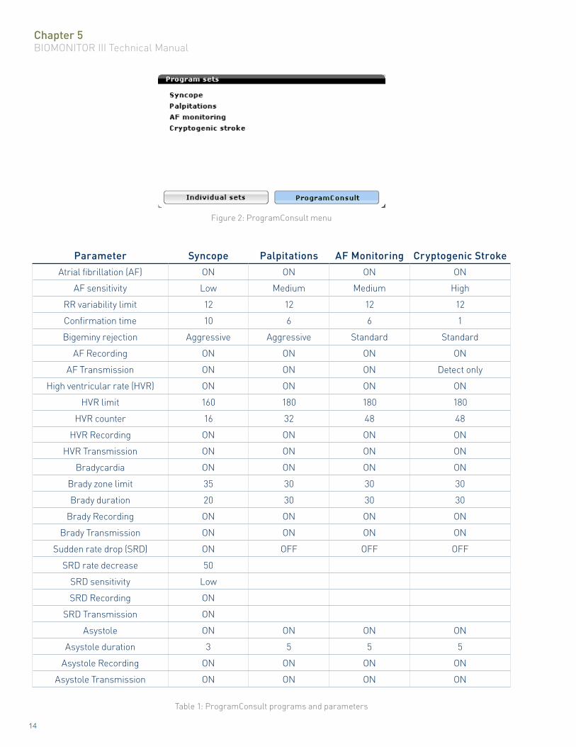
5.1.1 ProgramConsultThe ProgramConsult menu is located under Program sets and allows for the selection of a preconfigured programming set based on common patient indications. Selecting one of these options provides programming assistance by bundling the suggested recording criteria parameters to a single choice. The preconfigured programs, as well as their associated parameters are summarized in Table 1.
Chapter 5BIOMONITOR III Technical Manual
14
Figure 2: ProgramConsult menu
Parameter Syncope Palpitations AF Monitoring Cryptogenic StrokeAtrial fibrillation (AF) ON ON ON ON
AF sensitivity Low Medium Medium High
RR variability limit 12 12 12 12
Confirmation time 10 6 6 1
Bigeminy rejection Aggressive Aggressive Standard Standard
AF Recording ON ON ON ON
AF Transmission ON ON ON Detect only
High ventricular rate (HVR) ON ON ON ON
HVR limit 160 180 180 180
HVR counter 16 32 48 48
HVR Recording ON ON ON ON
HVR Transmission ON ON ON ON
Bradycardia ON ON ON ON
Brady zone limit 35 30 30 30
Brady duration 20 30 30 30
Brady Recording ON ON ON ON
Brady Transmission ON ON ON ON
Sudden rate drop (SRD) ON OFF OFF OFF
SRD rate decrease 50
SRD sensitivity Low
SRD Recording ON
SRD Transmission ON
Asystole ON ON ON ON
Asystole duration 3 5 5 5
Asystole Recording ON ON ON ON
Asystole Transmission ON ON ON ON
Table 1: ProgramConsult programs and parameters
Chapter 5BIOMONITOR III Technical Manual
15
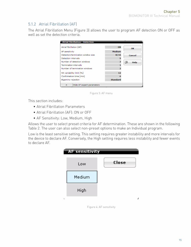
5.1.2 Atrial Fibrillation (AF)The Atrial Fibrillation Menu (Figure 3) allows the user to program AF detection ON or OFF as well as set the detection criteria.
Figure 3: AF menu
This section includes:• Atrial Fibrillation Parameters• Atrial Fibrillation (AF): ON or OFF• AF Sensitivity: Low, Medium, High
Allows the user to select preset criteria for AF determination. These are shown in the following Table 2. The user can also select non-preset options to make an Individual program.Low is the least sensitive setting. This setting requires greater instability and more intervals for the device to declare AF. Conversely, the High setting requires less instability and fewer events to declare AF.
Figure 4: AF sensitivity

Chapter 5BIOMONITOR III Technical Manual
16
Parameter Range Low Medium (Default) High
Atrial fibrillation detection OFF, ON On On On
Detection/termination window size 8/16, 16/24, 24/32 16/24 8/16 8/16
Detection intervals 5...(2)...23 11 5 5
Number of detection windows 1...(1)...4 3 2 1
Termination intervals 1...(2)...7 5 1 1
Number of termination windows 1...(1)...4 2 2 3
RR variability limit 6, 9, 12, 15, 18 % 12 12 12
Confirmation time 1...(1)...6; 10, 20, 30 min 6 6 6
Bigeminy rejection OFF, Standard, Aggressive Standard Standard Standard
Table 2: Parameter summary for AF sensitivity
RR VariabilityThis parameter represents the maximum percentage of variation between Vs-Vs cycle lengths to be considered stable by the device. The smaller the value, the greater the likelihood of AF being declared. Intervals greater than the RR Variability value from the mean cycle length will be considered AF intervals and count towards the detection and termination threshold.
Figure 5: RR variability limit
Detection/Termination Window SizeThe number of cycle lengths used to determine detection and termination of AF. Figure 6 shows the selectable values for Detection and Termination. For example, a Detection value of 8 means the device monitors groups of 8 cycle lengths to determine the RR variability by comparing each of those 8 events to the variability limit value.

Chapter 5BIOMONITOR III Technical Manual
17
If the number of events that are determined to be unstable exceed the programmed Detection interval value, AF suspicion criterion is met.A Termination criterion of 16 means the device is monitoring groups of 16 events. If the number of unstable events is greater than the programmed Termination value, the rhythm will continue to be considered unstable (AF).The Detection/Termination windows are not sliding windows, but consecutive windows.
Figure 6: Detection/termination window
Number of Detection WindowsNumber of consecutive windows that are required to be determined unstable for the device to start the confirmation time.
Figure 7: Number of detection windows
Chapter 5BIOMONITOR III Technical Manual
18
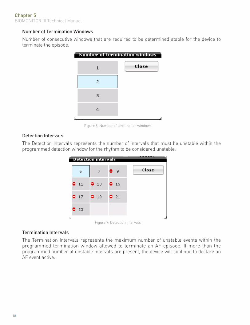
Number of Termination WindowsNumber of consecutive windows that are required to be determined stable for the device to terminate the episode.
Figure 8: Number of termination windows
Detection IntervalsThe Detection Intervals represents the number of intervals that must be unstable within the programmed detection window for the rhythm to be considered unstable.
Figure 9: Detection intervals
Termination IntervalsThe Termination Intervals represents the maximum number of unstable events within the programmed termination window allowed to terminate an AF episode. If more than the programmed number of unstable intervals are present, the device will continue to declare an AF event active.

Chapter 5BIOMONITOR III Technical Manual
19
Figure 10: Termination Intervals
Confirmation timeThe time before a recording of the AF event occurs. If the events are detected but do not reach the confirmation time period (suspicion phase), the event will not be counted.
Figure 11: Confirmation time
Bigeminy RejectionShort-long interval patterns indicative of bigeminy may be detected as AF. The bigeminy rejection parameter is designed to recognize these periodic interval patterns. When enabled to Standard, the bigeminy rhythms are recognized and prevented from triggering AF detections. The Aggressive setting is provided for more comprehensive filtering of complex bigeminy rhythms. The default setting for the bigeminy rejection parameter is Standard.NOTE: If bigeminy rejection is set to the parameter Aggressive, the AF sensitivity may be reduced.
5.1.3 High Ventricular Rate (HVR)BIOMONITOR III may be programmed to record high ventricular rate events using a rate limit and counter for criteria. Both the HVR limit and HVR counter criteria must be met for an event to be classified as a HVR episode. An event meeting the criteria would record an sECG and update the counters on the Diagnostics section of the device.

Chapter 5BIOMONITOR III Technical Manual
20
HVR LimitThis parameter value represents the lower rate limit required to be considered a HVR episode.
Figure 12: HVR limit
HVR CounterThis parameter value represents the count limit for high ventricular rate classification. This is an up/ down counter. Each event slower than the HVR limit decreases the count by 1, while each event faster than the HVR limit increments the counter by 1.
Figure 13: HVR counter
5.1.4 BradycardiaBradycardia Zone LimitRates determined to be below the programmed Bradycardia Zone Limit will be classified as a bradycardia event. In addition to the rate limit, the rate must also meet the bradycardia duration limit. This prevents single slow events from being classified as a bradycardia episode.
Figure 14: Bradycardia Zone Limit
Bradycardia DurationThe Brady Duration is the time over which the average heart rate is calculated. When the average heart rate is below the programmed bradycardia zone limit for the device, bradycardia is confirmed.

Chapter 5BIOMONITOR III Technical Manual
21
Figure 15: Brady duration
5.1.5 Sudden Rate Drop (SRD)SRD Rate DecreaseThis parameter value represents the percentage in rate decrease that triggers a Sudden Rate Drop event. The device compares the average rate of the most recent events (rate-drop intervals) and compares it to the average rate of the previous events (baseline intervals).
Figure 16: SRD rate decrease
SRD SensitivityThis parameter programs preset value setting for baseline intervals and rate-drop intervals.
Figure 17: SRD Sensitivity
Baseline IntervalsThis parameter value represents the number of averaged intervals to determine a baseline rate for sudden rate drop determination.
Figure 18: Baseline intervals

Chapter 5BIOMONITOR III Technical Manual
22
Rate-drop IntervalsThis parameter value represents the number of averaged intervals to determine a change in the heart rate. It uses the most recent events and determines the average rate of those events to determine the rate-drop rate value.
Figure 19: Rate-drop intervals
5.1.6 Asystole DurationAsystole DurationThe minimum total duration in seconds between R waves for the device to declare an Asystole event.
Figure 20: Asystole duration
5.1.7 Patient TriggerPatient TriggerThis is an ON/OFF feature which allows a patient to record an sECG by placing the Remote Assistant III over the device and pressing the button.
Figure 21: Patient trigger
Chapter 5BIOMONITOR III Technical Manual
23
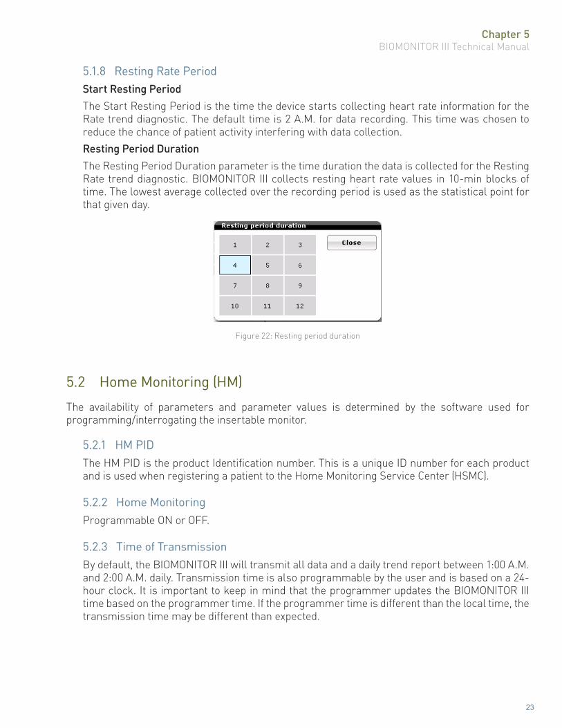
5.1.8 Resting Rate PeriodStart Resting PeriodThe Start Resting Period is the time the device starts collecting heart rate information for the Rate trend diagnostic. The default time is 2 A.M. for data recording. This time was chosen to reduce the chance of patient activity interfering with data collection.Resting Period DurationThe Resting Period Duration parameter is the time duration the data is collected for the Resting Rate trend diagnostic. BIOMONITOR III collects resting heart rate values in 10-min blocks of time. The lowest average collected over the recording period is used as the statistical point for that given day.
Figure 22: Resting period duration
5.2 Home Monitoring (HM)
The availability of parameters and parameter values is determined by the software used for programming/interrogating the insertable monitor.
5.2.1 HM PIDThe HM PID is the product Identification number. This is a unique ID number for each product and is used when registering a patient to the Home Monitoring Service Center (HSMC).
5.2.2 Home MonitoringProgrammable ON or OFF.
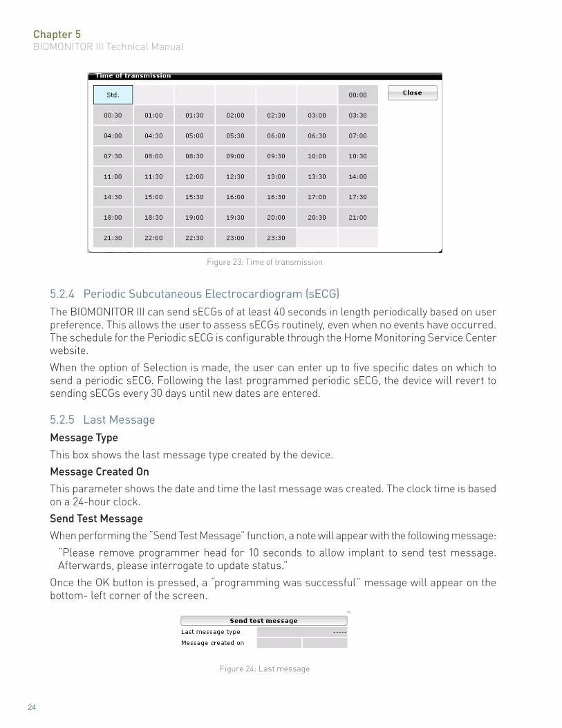
5.2.3 Time of TransmissionBy default, the BIOMONITOR III will transmit all data and a daily trend report between 1:00 A.M. and 2:00 A.M. daily. Transmission time is also programmable by the user and is based on a 24-hour clock. It is important to keep in mind that the programmer updates the BIOMONITOR III time based on the programmer time. If the programmer time is different than the local time, the transmission time may be different than expected.
Chapter 5BIOMONITOR III Technical Manual
24
Figure 23: Time of transmission
5.2.4 Periodic Subcutaneous Electrocardiogram (sECG)The BIOMONITOR III can send sECGs of at least 40 seconds in length periodically based on user preference. This allows the user to assess sECGs routinely, even when no events have occurred. The schedule for the Periodic sECG is configurable through the Home Monitoring Service Center website.When the option of Selection is made, the user can enter up to five specific dates on which to send a periodic sECG. Following the last programmed periodic sECG, the device will revert to sending sECGs every 30 days until new dates are entered.
5.2.5 Last MessageMessage TypeThis box shows the last message type created by the device.Message Created OnThis parameter shows the date and time the last message was created. The clock time is based on a 24-hour clock.Send Test MessageWhen performing the “Send Test Message” function, a note will appear with the following message:
“Please remove programmer head for 10 seconds to allow implant to send test message. Afterwards, please interrogate to update status.”
Once the OK button is pressed, a “programming was successful” message will appear on the bottom- left corner of the screen.
Figure 24: Last message

Chapter 5BIOMONITOR III Technical Manual
25
5.2.6 Episode Recording/TransmissionThis section provides an overview of which triggers are currently programmed ON for recordings, and also what triggers are set to transmit. Only if the device has recordings enabled for a particular trigger can the HM transmission option be selectable.
Figure 25: HM episode trigger
The user can modify the Recording and Transmission options. The only programmable options are ON and OFF with the exception of Atrial Fibrillation transmissions which also includes a Detect Only option. This option will transmit just the sECG for detection and not the one for termination.
Figure 26: Atrial fibrillation transmission options
5.3 Patient Data
This section allows the user to add patient, physician, hospital and other information. This information is stored in the device and can be accessed with any compatible programmer.The data in this section can be modified at any time.
5.3.1 IDThis section allows the user to input up to a 12-digit alphanumeric code to serve as a patient identifier. This may be a medical records number or a study number if the patient is enrolled in a study.
5.3.2 First / Last NameThese sections allow the user to input the patient’s first and last name into the memory of the device. This is a free text box, allowing up to 20 characters for the first name, as well as for the last name.Enter the patient’s name and select the enter key.

Chapter 5BIOMONITOR III Technical Manual
26
5.3.3 Date of BirthThis section allows the user to input the patient’s birth date. The birth date is entered as MM/DD/YYYY. When initially accessed, the current day will be displayed. The date can be changed using the following methods:
• Selecting the keypad icon to the left of the OK button will bring up a number keypad allowing the user to manually input the date.
• The day can be selected simply by touching the appropriate day on the screen.• Pressing the month will bring up a listing of the 12 months, and the user can select the
appropriate month.• Selecting the year will bring up a numeric keypad, allowing the user to enter a year.• The double arrow will change the year by one value each time it is touched. The left
double arrows decrease the value and the right double arrows increase the value.• The single arrow will change the month by one. The left arrow decreases the value and
the right arrow increases the value.Once the date is entered, select the OK button.
5.3.4 GenderThis section allows the user to select the patient’s gender.
5.3.5 Date of ImplantThe implantation date is entered by the user.
5.3.6 Hospital, CityThe hospital name and city name can be added. As with entering the patient’s name, up to 20 characters are available to add hospital and city information.
5.3.7 PhysicianThe physician name can be added. As with the patient name, up to 20 characters are available to add physician information. It is a good idea to add the physician’s first name also to help prevent confusion.
5.3.8 NYHAThis refers to the New York Heart Association classification. A value can be entered if it is known.
Figure 27: NYHA

Chapter 5BIOMONITOR III Technical Manual
27
5.3.9 SymptomThis section allows the user to select one or multiple symptoms related to the patient. Selecting a symptom will result in a check mark appearing in the box to the left. Once completed, press the OK button. The selection(s) will appear on the main patient page.
Figure 28: Symptom
5.3.10 EtiologyThis section allows the user to select an etiology related to the patient.
Figure 29: Etiology
5.3.11 RemarkThis section allows the user to input a remark for the patient up to 42 characters in length.

Chapter 5BIOMONITOR III Technical Manual
28
5.4 Sensitivity Settings
This section allows the user to change the SensingConsult, sensing filter settings, and stored/real-time signal choices.
Figure 30: Sensitivity setting
5.4.1 SensingConsultSensingConsult is a feature that allows the user to select a sensing profile to match the patient condition. Selecting one of these options results in the device automatically adjusting the threshold decay, reduction time, and threshold percentages to optimize sensing for that particular patient presentation. A preview image of the sensing profile is included on the left side of the screen.

Chapter 5BIOMONITOR III Technical Manual
29
Figure 31: SensingConsult options
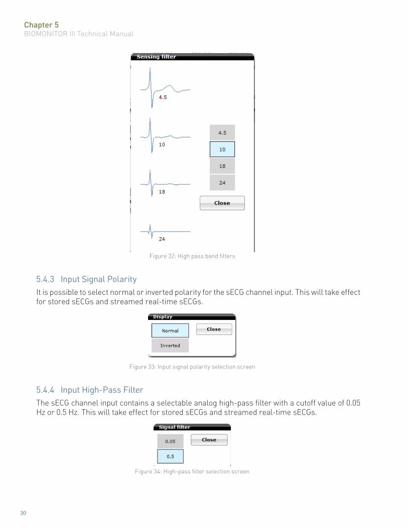
5.4.2 Sensing High Pass FilterThis section allows the user to change the filter setting of the signal. The higher the value, the more of the baseline and T-wave signals are removed from the sensing signal. This may be used if the baseline signal wanders or if oversensing from T-waves or P-waves occurs.
Chapter 5BIOMONITOR III Technical Manual
30
Figure 32: High pass band filters
5.4.3 Input Signal PolarityIt is possible to select normal or inverted polarity for the sECG channel input. This will take effect for stored sECGs and streamed real-time sECGs.
Figure 33: Input signal polarity selection screen
5.4.4 Input High-Pass FilterThe sECG channel input contains a selectable analog high-pass filter with a cutoff value of 0.05 Hz or 0.5 Hz. This will take effect for stored sECGs and streamed real-time sECGs.
Figure 34: High-pass filter selection screen

Chapter 6BIOMONITOR III Technical Manual
31
Chapter 6: Diagnostics
6.1 Diagnostics Overview
BIOMONITOR III can store a variety of statistical information. The various statistics consist of such features as rate histograms, rate trends, and activity trends, which are described in the following sections.AF Details
• AF Trends• AF Time of Occurrence• AF Duration• Ventricular rate during AF
Activity• Rate trends• Rate histograms• Activity trend
Sensing• R-wave trend• Noise duration trend
6.2 General Statistical Information
The BIOMONITOR III statistics modes are always in operation and cannot be selected OFF.The counters within the statistic features are reset each time the insertable monitor is permanently programmed.The histogram information is a 240-day duration. Afterwards, the oldest data are overwritten. Ongoing episodes are not counted.
6.3 Activity
The Activity diagnostic provides information related to heart rate, heart rate at rest, variability, rate histograms and activity.Data is collected for the most recent 240 days. The user can look at information for a specific day by using the left/right arrows on the lower left screen or by simply touching on the screen. The date is listed at the bottom of the graph with the data results at the top of the graph.

Chapter 6BIOMONITOR III Technical Manual
32
6.3.1 Rate TrendsHeart rate trends provide information related to heart rate, mean heart rate at rest and heart rate variability. Data is collected for the most recent 240 days. The user can look at information for a specific day by using the left/right arrows on the lower left screen or by simply touching on the screen. The date is listed at the bottom of the graph with the data results at the top of the graph.Heart rate information is based on the daily average heart rate and is displayed as a single data point for the day.BIOMONITOR III collects resting heart rate values in 10-minute blocks of time during the mean heart rate at rest recording time. The lowest average collected over the recording period is used as the statistical point for that given day.Heart rate variability is calculated using SDANN. Data is collected in five minute windows and calculated as a single daily data point.
Figure 35: Rate trends
6.3.2 Rate HistogramThe Rate histogram, shown in Figure 36, provides the percentage of activity in each rate bin for the BIOMONITOR III. Rate bins are divided into 10 bpm increments.
Figure 36: Rate histograms

Chapter 6BIOMONITOR III Technical Manual
33
6.3.3 Activity TrendThe Activity trend, shown in Figure 37, displays the daily percentage of activity as detected by the motion sensor of the device.
Figure 37: Activity trend
6.4 AF Details
6.4.1 AF TrendsThe AF trends diagnostic provides information related to the number and duration in hours of AF events on a daily basis.
Figure 38: AF trends

Chapter 6BIOMONITOR III Technical Manual
34
6.4.2 AF Time of OccurrenceThe time of occurrence, shown in Figure 39, summarizes the times of day that atrial tachyarrhythmia episodes began and is broken into three-hour time blocks. Knowing the time of day when atrial tachyarrhythmias begin may help determine whether a particular event will precipitate the tachyarrhythmia.The total number of events is listed at the bottom of the graph.
Figure 39: Time of occurrence
6.4.3 AF DurationAF duration shows the length of each AF episode in time bins and provides a percentage of the episodes which occur in each time bin versus the total number of episodes. Ongoing episodes are not counted on the graph.
Figure 40: AF duration

Chapter 6BIOMONITOR III Technical Manual
35
6.4.4 Ventricular Rate During AFThe ventricular rate during AF graph provides the mean and the maximum heart rate during AF. Large differences in the mean and maximum rates may indicate an irregular ventricular response during the AF while small differences may imply that ventricular rate is more stable during AF.
Figure 41: Ventricular rate during AF
6.5 Sensing
6.5.1 R-wave TrendThe R-wave trend provides average daily R-wave measurement values for up to 240 days.
Figure 42: R-wave trend

Chapter 6BIOMONITOR III Technical Manual
36
6.5.2 Noise Duration TrendThe noise duration trend provides the amount of noise sensed daily by the device, expressed as a percentage of time per day by the BIOMONITOR III. A high percentage of noise events could interfere with the BIOMONITOR III’s ability to detect arrhythmias.
Figure 43: Noise duration trend

Chapter 7BIOMONITOR III Technical Manual
37
Chapter 7: Other Functions/Features
BIOMONITOR III insertable monitors offer many additional functions and features to assist the physician in the care of the patient.
7.1 Home Monitoring
Home Monitoring enables the exchange of information about a patient’s cardiac status from the cardiac monitor to the physician. Home Monitoring can be used to provide the physician with reports from the BIOMONITOR III and can process them into graphical and tabular format called a Cardio Report. This information helps the physician optimize the diagnostic process, as it allows the patient to be scheduled for additional clinical appointments between regular follow-up visits if necessary.
7.2 Transmission of Information
The cardiac monitor transmits information with a small transmitter, which has a range of about 6 feet (2 meters). The patient’s cardiac monitor data are sent daily to the corresponding patient device and periodic sECGs are sent in configurable intervals when Home Monitoring is programmed ON.The minimal distance between the cardiac monitor and the patient device must be 8 inches (20 cm).
7.3 Patient Data
The patient device is designed for use in or away from the home. Power is supplied by a standard wall plug. The patient device can be placed on the patient’s nightstand or within 6 ft of where data transmission is to occur. Patient devices are either cell capable or plugged into a standard phone line.For additional information about the patient device, please refer to its manual.
7.4 Transmitting Data
The cardiac monitor’s information is digitally formatted by the BIOTRONIK Service Center and processed into a concise report called a Cardio Report. The Cardio Report, which is adjusted to the individual needs of the patient, contains current and previous cardiac monitor data. The Cardio Report is sent to the attending physician over the Internet. For more information on registering for Home Monitoring, contact your BIOTRONIK sales representative.The password protected BIOTRONIK Home Monitoring website can be accessed at the following URL:www.biotronik-homemonitoring.comAn online help menu is available in order to assist with the use of the Home Monitoring website.

Chapter 7BIOMONITOR III Technical Manual
38
Additionally, the attending physician may register to be informed of the occurrence of an Event Triggered Message through email or SMS (i.e., mobile phone) with a brief text message. If registered for Internet availability, the patient’s detailed cardiac monitor data can then be viewed by logging onto the Home Monitoring website.
7.5 Types of Report Transmissions
When the Home Monitoring function is activated, the transmission of a report (Cardio Report) from the implant can be triggered as follows:
• Trend report—the time period (daily) initiates the report.• Event report—the BIOMONITOR III detects certain events, which initiate a report.
Trend ReportThe time of the report transmission is programmable. For periodic messages, the time can be set anywhere between 00:00 and 23:30 hours. It is recommended to select a time between 0:00 and 4:00.The length of the time interval (monitoring interval) is preset to “daily.” For each monitoring interval, a data set is generated in the cardiac monitor and the transmission is initiated at the designated time.Event ReportWhen certain cardiac and technical events are detected by the cardiac monitor, a report transmission is automatically triggered. This is described as an “event message” as part of the daily transmission.The following clinical and technical events initiate a Home Monitoring message transmission:
• Event recording• ERI detected
NOTE: The attending physician can go to the Home Monitoring website to change or modify or modify the events he/she wishes to be informed.
7.6 Description of Transmitted Data
The Monitoring IntervalThe monitoring interval is the time period since the last periodic message was transmitted. In a periodic report, the monitoring interval since the previous periodic report is 24 hours.The following data are transmitted for the Cardio Report by the Home Monitoring system, when activated. In addition to the medical data, the serial number of the BIOMONITOR III is also transmitted.Device Status & Home Monitoring SettingsContains device and message identifying values that pertain to the cardiac monitor and Home Monitoring:
• Implantation Date• Device Status• Remaining capacity for ERI calculation (done by the Service Center)• Last follow-up
Chapter 7BIOMONITOR III Technical Manual
39
• Device Serial Number• Message Creation Date/Time• Device settings
Physiologic data• Heart rate• Heart rate variability• Patient activity• Temperature• Number of recordings and episode list
The temperature measurement feature alerts the physician to increased average temperature over 1-5 days compared to a 30-day baseline. This may indicate fever and allow physicians to determine whether further screening or follow-up is needed. Comparison of temperature measurements using this device and a conventional thermometer in swine warmed to increase their temperature by 1°C to mimic fever showed agreement within 0.1°C. Comparison of subcutaneous temperature measurements in humans to a conventional thermometer has not been performed.
7.7 Patient Data Memory
Individual patient data can be stored in the insertable monitor’s memory. The stored data is automatically displayed upon each interrogation. The patient data memory contains the following data categories:
• Patient ID (Code)• Patient Name• Date of Birth• Gender• Symptom• Etiology• Physician• Implantation Date• NYHA Class• Hospital• City• Phone• Remark

Chapter 7BIOMONITOR III Technical Manual
40
Symptom and etiology are specified using the European PASSPORT code system. The PASSPORT code is an identification system of two character codes that represent specific conditions. A listing of the codes available with definitions is displayed on the screen of the programmer when patient data is selected.When the patient data screen is entered symptom or etiology may be entered, and can be accessed following interrogation to check code definition.When the patient data screen is printed, the date of last follow-up is automatically given on the print-out.
7.8 Position Indicator
The position indicator facilitates positioning of the programmer head. The programmer optically and acoustically indicates whether the programmer head is in communication with the insertable monitor.
CAUTIONEMI – Computerized systems are subject to EMI or “noise”. In the sources of such disturbance, telemetry communication
may be interrupted and prevent programming.

Chapter 8BIOMONITOR III Technical Manual
41
Chapter 8: Product Storage and Handling
8.1 Sterilization and Storage
The insertable monitor is shipped in a cardboard box, equipped with a quality control seal, and product information label. The label contains the model specifications, technical data, serial number, expiration date, and sterilization and storage information of the insertable monitor. The monitor is preloaded in the insertion tool and an incision tool is also included in the package.The insertable monitor and its accessories have been sealed in a container and gas sterilized with ethylene oxide. To assure sterility, the container should be checked for integrity prior to opening. If a breach of sterility is suspected, return the insertable monitor to BIOTRONIK.
CAUTIONStorage (temperature) – Recommended storage temperature
range is -10° to 45°C (14°-113°F). Exposure to temperatures outside this range may result in cardiac monitor malfunction.
Handling – Do not drop. If an unpackaged insertable monitor is dropped onto a hard surface, return it to BIOTRONIK.
SHARP - Packaging includes an incision tool that is sharp and should be handled with care.
CAUTIONFOR SINGLE USE ONLY – Do not resterilize the
insertable monitor or accessories packaged with the cardiac monitor, they are intended for one-time use.
Device Packaging – Do not use the device if the packaging is wet, punctured, opened or damaged
because the integrity of the sterile packaging may be compromised. Return the device to BIOTRONIK.
Storage – Store the device in a clean area, away from sources of electromagnetic interference (EMI) to avoid
damage to the device. Use Before Date – Do not implant the device after
the USE BEFORE DATE because the device may have reduced longevity.
If a replacement insertable monitor is needed, contact your local BIOTRONIK representative.

Chapter 8BIOMONITOR III Technical Manual
42
This page left intentionally blank

Chapter 9BIOMONITOR III Technical Manual
43
Chapter 9: Follow-up Procedures
9.1 General Considerations
The insertable monitor follow-up serves to monitor and provide information related to the patient’s rhythm.The follow-up intervals are, therefore, primarily determined by medical judgment.The following notes are meant to stress certain product features, which are of importance for follow-up visits. For detailed information on follow-up procedures and medical aspects, please refer to the pertinent medical literature.NOTE: In order to enable full device functionality, including statistics functions and ERI detection, transmit a permanent program after insertion by pressing the [Transmit/Program] button.
9.2 Real-time sECG Transmission
The insertable monitors provide real-time transmission of the subcutaneous electrogram (sECG) to the programmer. The sECGs may be transmitted to the programmer via the programming head positioned over the inserted monitor. They are then displayed together with surface ECG and markers on the programmer screen and printed on the ECG recorder.
9.3 Follow-up Page
The follow-up page shown in Figure 44 provides information including the last follow-up date, the battery status, number of the diagnostics recordings and Home Monitoring status.
Figure 44: Follow-up page
The ECG and sECG signal display may be adjusted to make viewing easier by pressing on the icon shown in Figure 44.

Chapter 9BIOMONITOR III Technical Manual
44
9.4 Recordings
The Recordings page provides a list of stored episodes since the last time it was cleared. Information includes the time and date of the event, the duration, the type of event, mean heart rate and a sECG link to the recording.
Figure 45: Recordings page
9.5 sECG
BIOMONITOR III can store 60 minutes of sECGs. The types of sECG recording include HVR, Bradycardia, SRD, AF, Asystole and Patient triggered events.If sECG snapshots of all arrhythmia types are available, the minimum number of each type of snapshot in the device is the following:
Arrhythmia Type Number of Snapshots Episode recording scheme
AF 3 Oldest, newest, longest
High Ventricular Rate 3 Oldest, newest, longest
Bradycardia 3 Oldest, newest, longest
SRD 3 Two newest, oldest
Asystole 3 Two newest, oldest
Patient trigger 4 Four most recent
Table 3: Minimum number of episode snapshots

Chapter 9BIOMONITOR III Technical Manual
45
Examples of the different recordings are provided in the following sections. Figures 46-50 are for demonstration purposes only and are not clinically derived.
9.5.1 Atrial FibrillationFigure 46 shows an example of an atrial fibrillation recording with the sECG and marker channels. The device will record both when the episode meets detection criteria and when it meets termination cirteria. The user can scroll through the Holter and print only a section or the entire recording may be printed.
Figure 46: Atrial fibrillation sECG
9.5.2 High Ventricular RateFigure 47 shows an example of a high ventricular rate sECG. The black vertical bar indicates when the HVR criteria was met.
Figure 47: High ventricular rate sECG

Chapter 9BIOMONITOR III Technical Manual
46
9.5.3 BradycardiaFigure 48 shows an example of a bradycardia recording.
Figure 48: Bradycardia
9.5.4 AsystoleFigure 49 shows an Asystole recording.
Figure 49: Asystole
9.5.5 Patient TriggerFigure 50 shows a sECG recording from a patient trigger event.
Figure 50: Patient trigger
Chapter 10BIOMONITOR III Technical Manual
47
Chapter 10: Elective Replacement Indication (ERI)
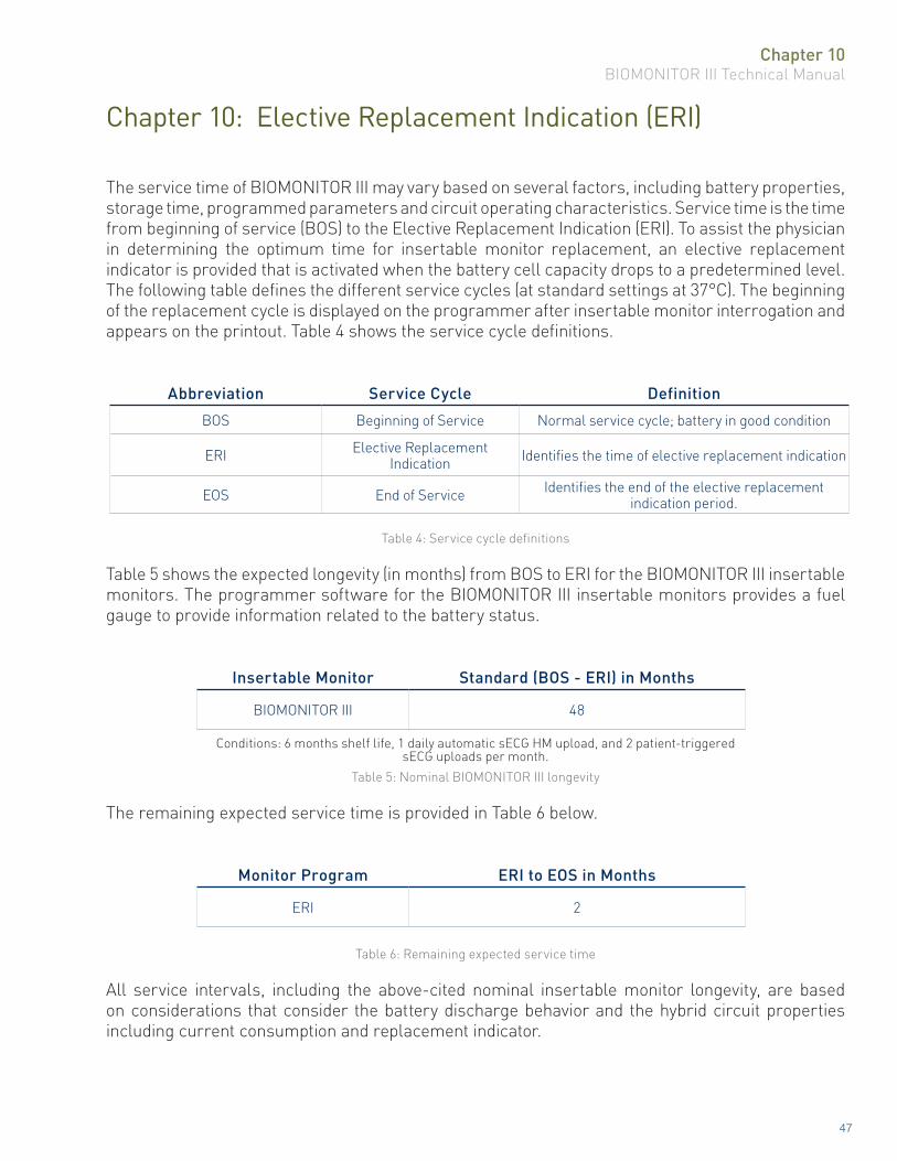
The service time of BIOMONITOR III may vary based on several factors, including battery properties, storage time, programmed parameters and circuit operating characteristics. Service time is the time from beginning of service (BOS) to the Elective Replacement Indication (ERI). To assist the physician in determining the optimum time for insertable monitor replacement, an elective replacement indicator is provided that is activated when the battery cell capacity drops to a predetermined level. The following table defines the different service cycles (at standard settings at 37°C). The beginning of the replacement cycle is displayed on the programmer after insertable monitor interrogation and appears on the printout. Table 4 shows the service cycle definitions.
Abbreviation Service Cycle Definition
BOS Beginning of Service Normal service cycle; battery in good condition
ERI Elective Replacement Indication Identifies the time of elective replacement indication
EOS End of Service Identifies the end of the elective replacement indication period.
Table 4: Service cycle definitions
Table 5 shows the expected longevity (in months) from BOS to ERI for the BIOMONITOR III insertable monitors. The programmer software for the BIOMONITOR III insertable monitors provides a fuel gauge to provide information related to the battery status.
Insertable Monitor Standard (BOS - ERI) in Months
BIOMONITOR III 48
Conditions: 6 months shelf life, 1 daily automatic sECG HM upload, and 2 patient-triggered sECG uploads per month.
Table 5: Nominal BIOMONITOR III longevity
The remaining expected service time is provided in Table 6 below.
Monitor Program ERI to EOS in Months
ERI 2
Table 6: Remaining expected service time
All service intervals, including the above-cited nominal insertable monitor longevity, are based on considerations that consider the battery discharge behavior and the hybrid circuit properties including current consumption and replacement indicator.

Chapter 10BIOMONITOR III Technical Manual
48
This page left intentionally blank
Chapter 11BIOMONITOR III Technical Manual
49
Chapter 11: Insertion/Removal
11.1 Opening the Sterile Container
The BIOMONITOR III is preloaded in the insertion tool and is packaged with an incision tool in a single container sterilized with ethylene oxide.
Peel off the sealing paper of the outer container as indicated by the arrow.
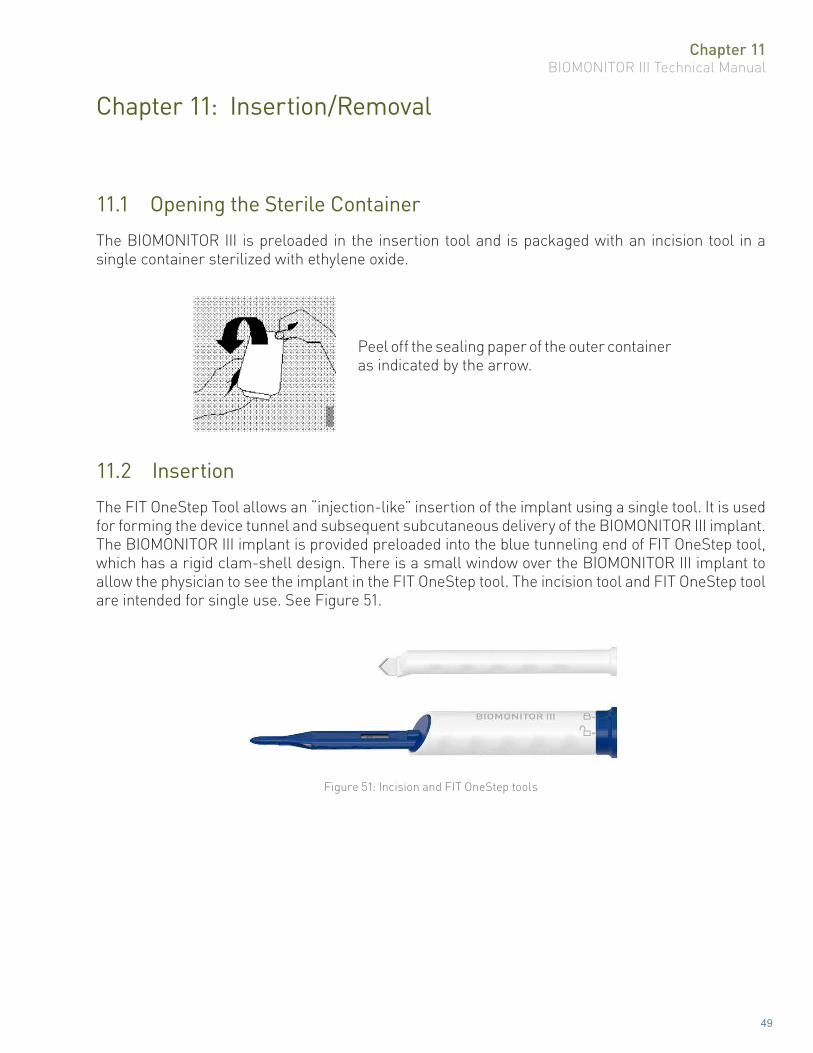
11.2 Insertion
The FIT OneStep Tool allows an “injection-like” insertion of the implant using a single tool. It is used for forming the device tunnel and subsequent subcutaneous delivery of the BIOMONITOR III implant. The BIOMONITOR III implant is provided preloaded into the blue tunneling end of FIT OneStep tool, which has a rigid clam-shell design. There is a small window over the BIOMONITOR III implant to allow the physician to see the implant in the FIT OneStep tool. The incision tool and FIT OneStep tool are intended for single use. See Figure 51.
Figure 51: Incision and FIT OneStep tools

Chapter 11BIOMONITOR III Technical Manual
50
BIOMONITOR III has been developed to be inserted in a close-fitting subcutaneous tunnel, preferably in or around the left side of the chest. Recommended locations are those areas close to the heart where the implant will be exposed to minimal movement from body positional changes or from arm movement. Suitable implant locations are shown below in Figure 52. In position A, a location between the suprasternal notch and the left nipple is shown. Position B shows an implant location of approximately 45° with respect to the midline. The choice of placement location is to be decided by the physician, on the basis of individual patient anatomy and comfort, as well as cosmetic considerations. The insertion process consists of four (4) intuitive steps: Incision, Tunneling, Unlocking and Retraction, see Table 7.
Figure 52: Two recommended positions for the placement for BIOMONITOR III

Chapter 11BIOMONITOR III Technical Manual
51
Step 1Local anesthetic agent is injected at the selected anatomical position, both along the incision line, and along the length of the planned tunnel. After an appropriate delay to allow the local anesthetic agent to take effect, the incision tool is used to make an incision through the skin. The physician is advised to consider the patient’s anatomy when making the incision.
Step 2The FIT OneStep Tool with the preloaded BIOMONITOR III implant is then advanced within a sub-dermal plane until the skin reaches the insertion stopping point, to create a tunnel for the BIOMONITOR III implant.
Step 3Once the tunneling part of the tool is fully inserted, the knob at the proximal end of the handle is turned counter-clockwise to the unlocked icon.
Step 4Holding the outer white portion of the handle stationary against the incision, retract the blue inner portion by pulling back and away from the white portion. The implant will remain in place within the tunnel.
ICM insertion has been associated with a small risk of device migration and loss through the incision. To help promote healing and device integrity, closure of the incision, in addition to skin dressing, should be considered for at risk patients. The protection of the wound from environmental influences finalizes the insertion procedure for BIOMONITOR III.
Table 7: BIOMONITOR III insertion procedure

Chapter 11BIOMONITOR III Technical Manual
52
11.3 Removal
Removed cardiac monitors or accessories may not be reused. Removed cardiac monitors can be sent either to the local BIOTRONIK representative or the BIOTRONIK home office for expert disposal. If possible, the removed cardiac monitor should be cleaned with a sodium-hyperchlorite solution of at least 1% chlorine and, thereafter, washed with water prior to shipping.The insertable monitor should be removed before the cremation of a deceased patient.
CAUTIONDevice Incineration – Never incinerate a removed cardiac
monitor. Be sure the insertable cardiac monitor is explanted before a patient who has died is cremated.
Removed Devices – Return all removed devices to BIOTRONIK.
11.4 Reasons to Remove an Insertable Monitor
An insertable monitor may be removed emergently or at a physician’s discretion at any time subsequent to an implant procedure. Reasons for removal include, but are not limited to: patient death; loss of sensing; inability to program/interrogate the inserted monitor; infection, ERI/EOS (normal or premature); system upgrade; physician preference for another insertable monitor model; and/or other reason(s) which may or may not be known to the insertable monitor manufacturer. Complications related to other portions of the insertable monitor system (i.e., patient) may also result in insertable monitor removal.Table 8 summarizes some of the more common reasons for insertable monitor removal.
Source Cause Possible Effect
Battery Premature depletion or other cause(s) resulting in excessive battery current drain. Inability to program/interrogate; sensing difficulty.
Circuitry
Electrical parameter changes due to shorts, opens, or component parametric drift
Electromagnetic Interference (EMI) from large power tools, industrial equipment, electrocautery, defibrillation, radiation
therapy, RF ablation therapy, etc.
Reversion to “Elective Replacement” or electrical reset parameters; inability to program/ interrogate;
other damage to circuit components resulting in permanent or temporary parameter changes.
Patient
Normal medical complication Infection
Body rejection phenomena Fluid accumulation; migration; erosion.
Physician preference Upgrade to an implantable cardiac pacemaker or implantable cardioverter defibrillator.
Table 8: Common reasons to remove an insertable monitor
Chapter 12BIOMONITOR III Technical Manual
53
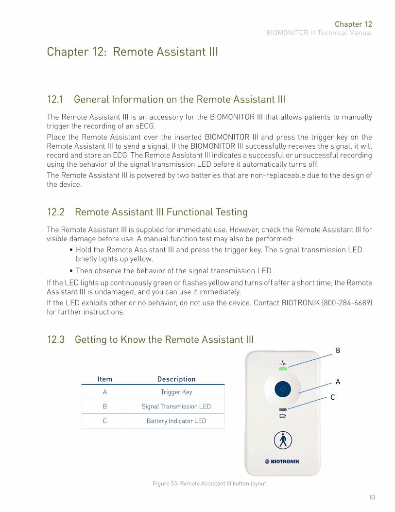
Chapter 12: Remote Assistant III
12.1 General Information on the Remote Assistant III
The Remote Assistant III is an accessory for the BIOMONITOR III that allows patients to manually trigger the recording of an sECG.Place the Remote Assistant over the inserted BIOMONITOR III and press the trigger key on the Remote Assistant III to send a signal. If the BIOMONITOR III successfully receives the signal, it will record and store an ECG. The Remote Assistant III indicates a successful or unsuccessful recording using the behavior of the signal transmission LED before it automatically turns off.The Remote Assistant III is powered by two batteries that are non-replaceable due to the design of the device.
12.2 Remote Assistant III Functional Testing
The Remote Assistant III is supplied for immediate use. However, check the Remote Assistant III for visible damage before use. A manual function test may also be performed:
• Hold the Remote Assistant III and press the trigger key. The signal transmission LED briefly lights up yellow.
• Then observe the behavior of the signal transmission LED.If the LED lights up continuously green or flashes yellow and turns off after a short time, the Remote Assistant III is undamaged, and you can use it immediately.If the LED exhibits other or no behavior, do not use the device. Contact BIOTRONIK (800-284-6689) for further instructions.
12.3 Getting to Know the Remote Assistant III
Item Description
A Trigger Key
B Signal Transmission LED
C Battery Indicator LED
Figure 53: Remote Assistant III button layout

Chapter 12BIOMONITOR III Technical Manual
54
12.4 Triggering a Manual Recording
1. The patient holds the Remote Assistant III over his or her chest as close as possible to the location where the BIOMONITOR III was implanted. Make sure that the Remote Assistant III lies with its backside flat on the chest without a gap or finger in between.
2. The trigger key is pressed and the Remote Assistant III is kept over the implanted cardiac monitor for at least three seconds.
The device emits an acoustic signal, and the signal transmission LED lights up continuously yellow for approximately three seconds.3. If the recording has been successfully triggered in the BIOMONITOR III, the signal
transmission LED lights up continuously green for a maximum of 30 seconds before the device automatically turns off. If the signal transmission LED flashes yellow, no recording was triggered in the BIOMONITOR III. In this case, re-position the Remote Assistant III and try again.
12.5 Battery LED Indicator Explained
LED behavior Explanation
LED is not lit The battery in the Remote Assistant III has sufficient capacity.
LED flashes yellow The battery’s capacity is only sufficient for another approx. 20 trigger attempts.
LED is continuously lit yellow The device is defective or the battery’s capacity is depleted.
12.6 Signal Transmission LED Explained
LED behavior Explanation
LED is continuously lit yellow The trigger key has been pressed.
LED flashes yellow Recording in the BIOMONITOR III was not successfully triggered.
LED is continuously lit green Recording in the BIOMONITOR III was triggered successfully.
Chapter 13BIOMONITOR III Technical Manual
55
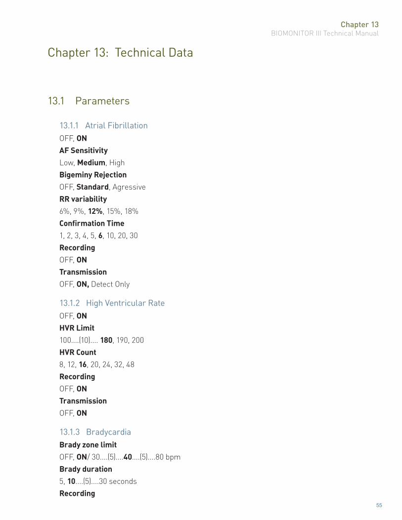
Chapter 13: Technical Data
13.1 Parameters
13.1.1 Atrial FibrillationOFF, ON AF Sensitivity Low, Medium, High Bigeminy RejectionOFF, Standard, AgressiveRR variability6%, 9%, 12%, 15%, 18%Confirmation Time1, 2, 3, 4, 5, 6, 10, 20, 30RecordingOFF, ONTransmissionOFF, ON, Detect Only
13.1.2 High Ventricular RateOFF, ONHVR Limit100....(10).... 180, 190, 200HVR Count8, 12, 16, 20, 24, 32, 48RecordingOFF, ONTransmissionOFF, ON
13.1.3 BradycardiaBrady zone limitOFF, ON/ 30....(5)....40....(5)....80 bpmBrady duration5, 10....(5)....30 secondsRecording
Chapter 13BIOMONITOR III Technical Manual
56
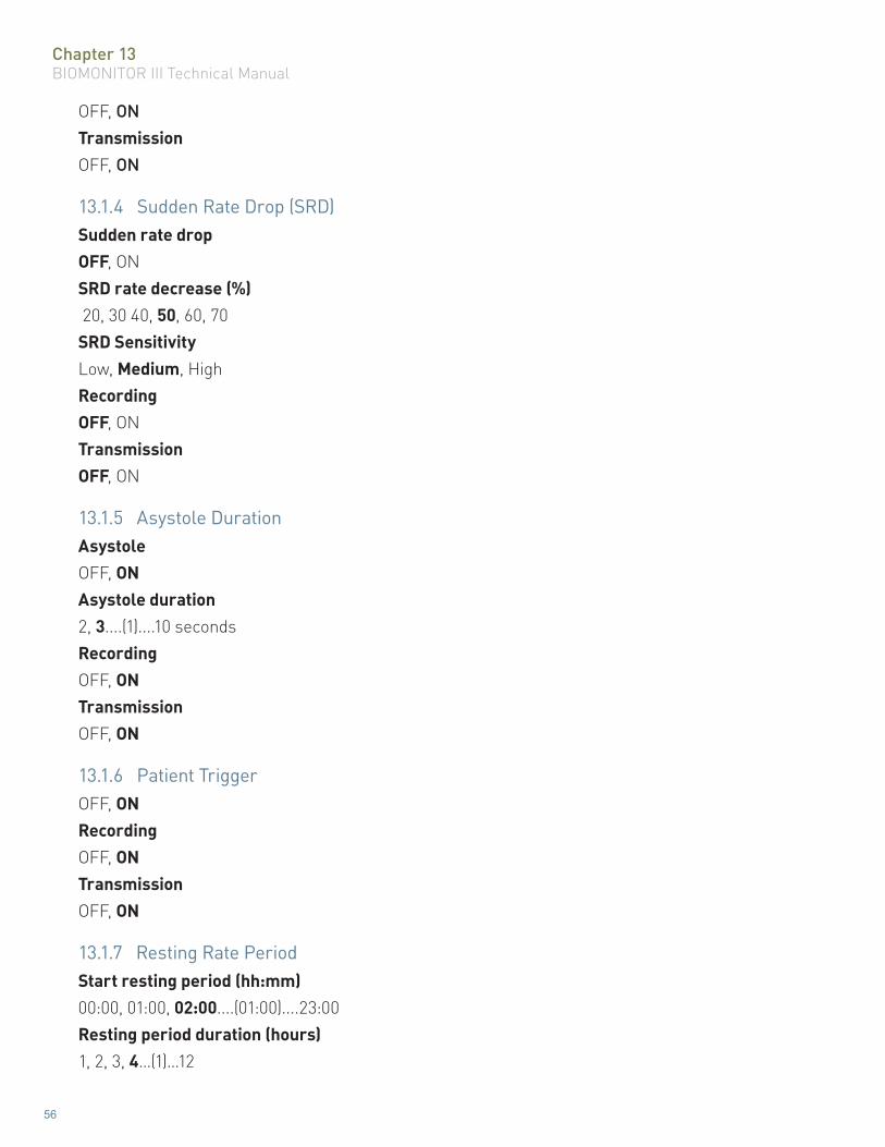
OFF, ONTransmissionOFF, ON
13.1.4 Sudden Rate Drop (SRD)Sudden rate dropOFF, ONSRD rate decrease (%) 20, 30 40, 50, 60, 70SRD SensitivityLow, Medium, HighRecordingOFF, ONTransmissionOFF, ON
13.1.5 Asystole DurationAsystoleOFF, ONAsystole duration2, 3....(1)....10 secondsRecordingOFF, ONTransmissionOFF, ON
13.1.6 Patient TriggerOFF, ONRecordingOFF, ONTransmissionOFF, ON
13.1.7 Resting Rate PeriodStart resting period (hh:mm)00:00, 01:00, 02:00....(01:00)....23:00Resting period duration (hours)1, 2, 3, 4…(1)…12
Chapter 13BIOMONITOR III Technical Manual
57
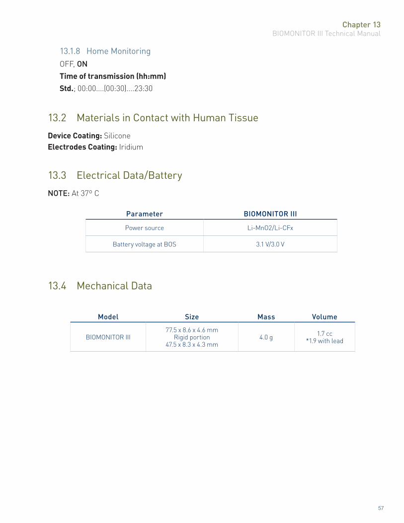
13.1.8 Home MonitoringOFF, ON Time of transmission (hh:mm) Std.; 00:00....(00:30)....23:30
13.2 Materials in Contact with Human Tissue
Device Coating: SiliconeElectrodes Coating: Iridium
13.3 Electrical Data/Battery
NOTE: At 37º C
Parameter BIOMONITOR III
Power source Li-MnO2/Li-CFx
Battery voltage at BOS 3.1 V/3.0 V
13.4 Mechanical Data
Model Size Mass Volume
BIOMONITOR III77.5 x 8.6 x 4.6 mm
Rigid portion 47.5 x 8.3 x 4.3 mm
4.0 g 1.7 cc*1.9 with lead

Chapter 13BIOMONITOR III Technical Manual
58
This page left intentionally blank

Chapter 14BIOMONITOR III Technical Manual
59
Chapter 14: AF Detection Study Results
In order to evaluate BioMonitor AF detection performance, clinical data was collected in a single-center, prospective, nonrandomized study. The ability of BioMonitor to detect episodes of AF was quantified in comparison with the gold standard, expert-annotated, external Holter ECG recorder. Sixty-six (66) participants with suspected paroxysmal or persistent atrial fibrillation who had been implanted with a BioMonitor were additionally equipped with an external Holter ECG recorder. Of these 66 participants, 39 showed at least one true AF episode during the two-day Holter period. A total of 146 AF episodes were annotated from 2,878 hours of Holter ECG data.False positive AF episodes (i.e., non-AF periods falsely detected as AF by BioMonitor), resulting in positive predictive values less than 100%, were predominantly associated with episodes of ectopic beats.False negative AF episodes (i.e., true AF episodes undetected by BioMonitor), resulting in sensitivity values less than 100%, were mainly attributed to R-R interval variability that did not exceed the BioMonitor-programmed limit of 12.5% for a sufficient fraction of intervals. All of these FN patients had AF documented by the BioMonitor in another episode and were thus identified as AF positive patients.Table 9 summarizes the mean episode sensitivity and a mean episode PPV.
Sensitivity (%) ± SD PPV (%) ± SD
95.4 ± 13.3 76.3 ± 38.7
Table 9: Mean BioMonitor AF detection performance statistics.
14.1 BioMonitor 2 Pilot Study Results
The objective of this study was to provide clinical data of the insertion procedure and the sensing quality of BIOTRONIK’s second generation of Insertable Cardiac Monitor (ICM) BioMonitor 2. Data of 30 patients from five Australian clinical sites from December 18, 2014 through July 06, 2015 are included in this summary.There were 22 male and 8 female subjects enrolled with a mean age of 63 years. The most common indications for insertion of the BioMonitor 2 were syncope and symptomatic or asymptomatic atrial fibrillation.The median time between first skin cut to final successful positioning of BioMonitor 2 was 2.5 minutes. The mean time of the entire implantation procedure was 9.9 minutes. Inserting investigators evaluated the tunneling procedure with the FIT 1 tool related to the needed force and grip on the tool, which resulted in a rating of good or acceptable in 83% and 100% of the cases respectively. The FIT 2 tool was evaluated by the inserting investigator for implant loading, insertion, removal and overall handling. All assessment were good or acceptable.
Chapter 14BIOMONITOR III Technical Manual
60
The mean R-wave amplitude at the 1-week and 1-month follow-up visit was 0.7 ± 0.4 mV and 0.8± 0.4 mV respectively. The results show significant superiority to the mean R-wave amplitude of the predecessor BioMonitor (0.3 mV). The mean noise burden was 1.3 ± 2.3 % and 2.3 ± 3.1 % at the 1-week and 1-month follow-up respectively. The results are significantly improved compared to the predecessor device (5.5%). Five patients reported pain in the pocket during the first week afterimplantation. Medical treatment was not needed. One patient had a wound infection which was treated with oral antibiotics.The results demonstrate safety and efficacy of the insertion procedure and the study device.
14.2 BioInsight Study Results
The BioInsight study was designed to evaluate the safety and feasibility of performing the BioMonitor 2 insertion procedure in an office setting. All subjects enrolled in the study had an approved indication for continuous arrhythmia monitoring with an ICM and were implanted with a US market released BIOTRONIK BioMonitor 2. The primary objective was to characterize all insertion procedure-related adverse events requiring additional invasive intervention to resolve though the 90-day follow-up. Secondary objectives included characterization of all insertion procedure-related adverse events not included in the primary objective, characterization of the insertion procedure, and characterization of device functionality post-insertion. Of 82 subjects enrolled at 6 study sites in the U.S., 77 patients underwent an insertion procedure in an office setting. All insertion procedure attempts were successful. There were no reported adverse events that met the criteria for primary objective 1; therefore, the rate of all insertion procedure-related adverse events that required additional invasive intervention to resolve is 0%, 95% CI: (0.0%, 5.0%).Only two adverse events were reported and both were classified as insertion procedure-related that did not require additional invasive intervention to resolve. The overall event rate for all reported adverse events was 2.7%, 95% CI: (0.3%, 9.5%) and is similar to in-office ICM insertion rates reported in literature. The average R-wave amplitude was 0.77 ± 0.5 mV at insertion and 0.67 ± 0.3 mV at 90 days. The average noise burden was 2.5 ± 4.64 % at wound check and 2.7 ± 5.79% at 90 days.Daily BIOTRONIK Home Monitoring® transmissions for 76 subjects showed stable R-wave amplitudes and noise burden through the 90-days post-insertion with an overall average of 0.68 mV and 2.7%, respectively.

Chapter 15BIOMONITOR III Technical Manual
61
Chapter 15: Order Information
Insertable Monitor Type Order Number
BIOMONITOR III 436066
FCC Statement: (FCC ID: QRIBM2): This transmitter is authorized by rule under the Medical Device Radiocommunication Service (in part 95 of the FCC Rules) and must not cause harmful interference to stations operating in the 400.150-406.000 MHz band in the Meteorological Aids (i.e., transmitters and receivers used to communicate weather data), the Meteorological Satellite, or the Earth Exploration Satellite Services and must accept interference that may be caused by such stations, including interference that may cause undesired operation. This transmitter shall be used only in accordance with the FCC Rules governing the Medical Device Radiocommunication Service. Analog and digital voice communications are prohibited. Although this transmitter has been approved by the Federal Communications Commission, there is no guarantee that it will not receive interference or that any particular transmission from this transmitter will be free from interference.This device complies with part 15 of the FCC Rules. Operation is subject to the following two conditions:
(1) This device may not cause harmful interference, and(2) This device must accept any interference received, including interference that may
cause undesired operation

Chapter 15BIOMONITOR III Technical Manual
62
This page left intentionally blank

Chapter 15BIOMONITOR III Technical Manual
63
This page left intentionally blank

BIOTRONIK, Inc.6024 Jean RoadLake Oswego, OR 97035-5369(800) 547-0394 (24-hour) (800) 291-0470 (fax)www.biotronik.com
M4220-C 12/20© 2020 BIOTRONIK, Inc. All rights reserved. MN086r4 12/10/20