bioness inc rye canyon loop valencia, ca usa telephone: or
TRANSCRIPT

Manufacturer:Bioness Inc25103 Rye Canyon LoopValencia, CA 91355 USATelephone: 800.211.9136 or 661.362.4850Email: [email protected]: www.bioness.com
European Authorized Representative:NESS Europe B.V. Stationsweg 413331 LR Zwijndrecht, The NetherlandsTelephone: +31.78.625.6088 Email: [email protected]: www.bioness.com
612-00624-001 Rev. A06/2013
Vector Gait and Safety SystemTM, Bioness, the Bioness Logo®, and LiveOn® are registered trademarks of Bioness Inc. in the United States or other countries | www.bioness.com
©2013 Bioness Inc.All Rights Reserved
No part of this publication may be reproduced, transmitted, transcribed, stored in a retrieval system, or translated into any language or any computer language, in any form or by any third party, without the prior written permission of Bioness Inc. DisclaimerBioness Inc and its affiliates shall not be liable for any injury or damage suffered by any person, either directly or indirectly, as a result of the unauthorized use or repair of Bioness Inc products. Bioness Inc and its affiliates do not accept any responsibility for any damage caused to its products, either directly or indirectly, as a result of use and/or repair by unauthorized personnel.

Clinician's Guide
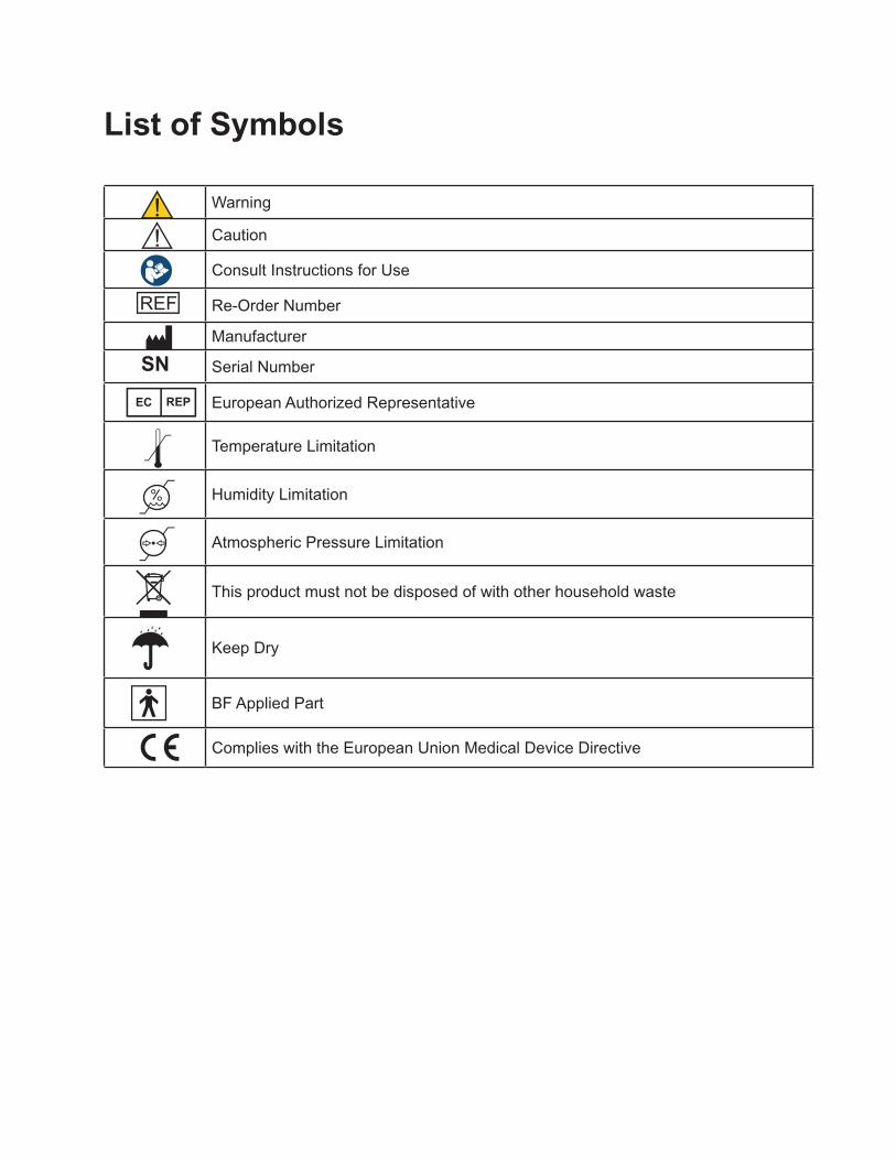
List of Symbols
Warning
Caution
Consult Instructions for Use
Re-Order Number
Manufacturer
SN Serial Number
European Authorized Representative
Temperature Limitation
Humidity Limitation
Atmospheric Pressure Limitation
This product must not be disposed of with other household waste
Keep Dry
BF Applied Part
Complies with the European Union Medical Device Directive

Table of ContentsChapter 1: Introduction ........................................................................................................ 1
Device Description .......................................................................................................................................1
Chapter 2: Warnings and Cautions ....................................................................................... 3
Intended Use ...............................................................................................................................................3
Contraindications .........................................................................................................................................3
Precautions ..................................................................................................................................................3
Warnings .....................................................................................................................................................3
Chapter 3: Patient Harness Fitting ....................................................................................... 5
Selecting a Harness Size ............................................................................................................................5
Donning a Patient Harness ..........................................................................................................................5
Chapter 4: Starting the Vector Elite System and Software ................................................... 7
Turning the system on and off ......................................................................................................................7
Launching the Vector Gait and Safety Software ...........................................................................................8
Chapter 5: Patient Training Menu ...................................................................................... 11
Creating a New Patient Account ................................................................................................................ 11
Opening an Existing Patient Account .........................................................................................................12
Training Session Screen ............................................................................................................................13
Manual Control ...........................................................................................................................................14
Attaching a Patient Harness to the Spreader Bar .......................................................................................14
Training Controls ........................................................................................................................................16
Trolley Tracking ...................................................................................................................................16
Dynamic Body Weight Support ............................................................................................................17
Dynamic Unloading ..............................................................................................................................17
Fall Limit ...............................................................................................................................................18
Session Status Section ...............................................................................................................................18
Starting a Training Session .........................................................................................................................18
Fall Limit Detection .....................................................................................................................................20
Stopping a Training Session .......................................................................................................................21
Emergency Stop and Emergency Lower Buttons .......................................................................................21
Session Summary Screen ..........................................................................................................................22

Vector Elite Time Out Feature ....................................................................................................................23
Chapter 6: Manual Controls, Summaries, and Reference Material Menus .......................... 25
Manual Control Menu .................................................................................................................................25
Patient Summaries Menu ...........................................................................................................................26
Reference Material Library Menu ...............................................................................................................29
Chapter 7: Vector Elite Remote Control ............................................................................ 31
Remote Control Software Navigation .........................................................................................................31
Manual Control Screen ...............................................................................................................................32
Training Controls Screen ............................................................................................................................33
Session Status Screen ...............................................................................................................................34
Take Control Screen ...................................................................................................................................35
Using the Remote Control for a Patient Training Session ......................................................................... 37
Using the Remote Control to Operate System without Patient Data ........................................................ 38
Chapter 8: Vector Elite Software Administrator Menu ........................................................ 41
Accessing the Administrator Menu .............................................................................................................39
Patient Database .................................................................................................................................41
Add User ..............................................................................................................................................41
Backup and Restore Database Menu ..................................................................................................42
Chapter 9: Service and Maintenance .................................................................................. 45
Chapter 10: Technical Specifications ................................................................................. 47

1Chapter
1Chapter 1 - Introduction
Introduction Introduction of Vector Gait and Safety System™
The Vector Elite is a body weight support system designed to accelerate physical rehabilitation of patients with severe gait or balance impairment. The system provides dynamic body weight support and trolley tracking, enabling the patient to practice gait and balance training with less than a full body weight. When using the Vector Elite System a computer controlled motor keeps the trolley at a desired location relative to the patient, and a separate computer controlled motor ensures that the rope tension is kept at a desired value. The patient may walk along a predetermined path or on a treadmill. The system receives control signals through an encrypted WiFi signal from a PC or remote control.
Figure 1-1: Vector Elite Trolley
Device Description:
The Vector Elite System consists of a mechanical track, a power rail, a power station, a motorized trolley with rope, a spreader bar, PC computer with proprietary software and an optional remote control.
Mechanical Track and Power Rail
The mechanical track is mounted overhead, typically attached to a support beam, floor or truss, and the trolley runs along the track. The mechanical track defines the horizontal aspect of the walking path of the patient. The track includes straight and curved portions that form a closed loop track.
Mechanical Track
Trolley Rope
Spreader Bar
Vector Elite Trolley
Power Rail
2 Clinician's Guide
The power rail is also mounted overhead, and runs parallel to the mechanical track. The power rail delivers electricity to the Elite trolley.
Power Station
The power station is mounted to a wall and plugs into an outlet. It converts electrical power from the building to a predetermined power level, which is supplied to the trolley through the power rail. The power station also contains an electrical isolation transformer, as a safety feature of the system.
Elite Trolley
The Elite Trolley consists of two motors and a rope that attaches to the spreader bar. When using the Vector Elite System a computer controlled motor keeps the trolley at a desired location relative to the patient, and a separate computer controlled motor ensures that the rope tension is kept at a desired value. The trolley moves along the entire length of the track.
Spreader Bar
The spreader bar is a device that enables the attachment of a patient harness to the trolley rope. The spreader bar attaches to a patient harness at two points. On each side of the spreader bar there are three holes built to accommodate patients of different widths.
PC
The touch screen PC contains the software that controls the Vector Elite System and manages the secure patient database. The Vector Gait and Safety System Software is password protected and communicates with the trolley through an encrypted WiFi signal.
Remote Control
The remote control is an optional accessory that may be used to control the System once a training session has begun. This accessory is not necessary to operate the Vector Elite System. The remote control uses an Android Operating System with a Vector Gait and Safety System Application and communicates with the trolley through an encrypted WiFi signal.
Chapter
3
Warnings and Cautions Intended Use
The Vector Elite System is a body weight support system designed to accelerate physical rehabilitation of patients with severe gait and/or balance impairment. The system unloads a programmed amount of the patient’s weight thus enabling the patient to practice walking with less than a full body weight.
Contraindications
Prior to use all patients need to be deemed medically stable and appropriate by a Vector Gait and Safety System trained healthcare professional. Patients with the following diagnoses or symptoms should not use the Vector Base System:
• Patients that weigh more than 400 lbs (181.4 kg)
• Unstable fractures
• Halo neck supports
• Uncontrolled hypertension
• Uncontrolled diabetes
• Severe osteoporosis
Precautions
• Pulling down on the spreader bar and then letting go could cause injury; use with caution.
• For correct usage, ensure that the patient harness connection to the spreader bar is not too narrow or too wide.
• Use care when assisting patients into/out of a harness as they can get tangled and fall.
• Follow instructions carefully to prevent pulling or jerking of the patient in the equipment.
• Carefully measure and fit a harness to the patient. Incorrect sizing may cause discomfort and/or injury to the patient.
• Use care when attaching a patient harness to the spreader bar. If not attached correctly, there is a risk of the patient falling.
Warnings
• Incorrect patient data entry or incorrect patient retrieval may cause the patient to fall and/or serious injury.
• Do not place a patient that weighs more than 400 lbs (181.4kg) in the Vector Gait and Safety System.
Chapter 2 - Warnings and Cautions
2

4 Clinician's Guide
• Do not exceed recommended weight limits or otherwise misuse the equipment as the equipment can dislocate and fall causing serious injury.
• Do not lift the patient too high or have the patient ascend/descend high stairs where they might be injured from the trolley.
• Do not touch the motorized Elite trolley during a training session. The trolley contains moving parts that could cause injury if touched.
• In an emergency such as an electrical outage, stop exercise immediately to avoid injury and turn off the power switch located on the power station.
• Do not attempt to service or repair the Vector Elite System or electrocution may occur.
• Do not modify the Vector Elite System equipment; doing so would void the warranty.
• Do not use the Vector Elite System if maintenance is required; serious injury may occur.
• In the event of power failure, carefully remove patient from the harness and step away from the equipment.
• Do not use equipment if the Elite trolley has become wet (e.g. with sprinklers) as there is a risk of electrocution. Servicing is required before the equipment may be used.
• To avoid risk of electric shock, this equipment must only be connected to a supply mains with protective earth.
• The Vector Elite System is not intended for patient transport. Using the system as a transport could cause serious patient injury.
• Do not manually move the trolley along the track by pulling on the trolley rope this could damage the Vector Elite System.
• The Vector Gait and Safety System may only be operated by a trained healthcare professional.
• The use of accessories not specified by the manufacturer may result in increased emissions by, or decreased immunity of the equipment, affecting its performance.
• There is a possibility of electromagnetic interference with other devices. When there is suspicion of possible EMC interference to Vector Gait and Safety System, it is recommended to shut down the electrical devices nearby, one-by-one, to locate the possible interference source.

Chapter
5
Patient Harness Fitting The Vector Elite System is used with a patient harness. The sizing chart and fitting instructions in this chapter are for the Maine Anti-Gravity Systems patient harness and are for demonstration purposes only. Instructions for other patient harness devices may vary, please refer to device label for further information.
Selecting a Harness Size
It is important to make sure that the proper size harness is selected for a patient to ensure safety and effectiveness while using the Vector Base System. Refer to Table 3-1 for harness sizing.
Harness Size Waist Size 1 Harness Color Code
X-Small 24”-28” (60 cm - 71 cm) Gray
Small 28”-32” (71 cm - 81 cm) Yellow
Medium 32”-36” (81 cm - 91 cm) Red
Double Medium 34”-38” (91 cm - 96 cm) Purple
Large 36”-40” (96 cm - 101 cm) Blue
X-Large 40”-44” (101 cm - 111 cm) Green
2X-Large 44”-48” (111 cm - 121 cm) White
3X-Large 48”-52” (121 cm - 132 cm) Orange
4X-Large 52”56” (132 cm - 142 cm) Brown
5X-Large 56”-60” (142 cm - 152 cm) Pink1 Waist Size is determined by measuring 2 in (5 cm) below the umbilicus (belly button) tightly around the torso.
Table 3-1: Maine Anti-Gravity Systems Patient Harness Sizing Chart.
Donning a Patient Harness
CAUTION: Inspect the harness prior to use. Do not use if harness straps are torn, if there is separation in the harness stitching, or if the Velcro is unable to adhere. Contact Bioness.
1. Detach all Velcro attachments to open the vest.
2. Make sure the patient is in a secured position.
3. Have the patient put their arms through the shoulder straps to put on the vest. The open side of the vest will face the front.
4. Secure the lower abdominal support first by attaching the Velcro. Make sure the support is as tight as possible.
5. Next secure the upper abdominal support by attaching the Velcro. Note: This is the middle support with the netting material on the back.
6. Securely attach the top torso support.
Chapter 3 - Patient Harness Fitting
3
6 Clinician's Guide
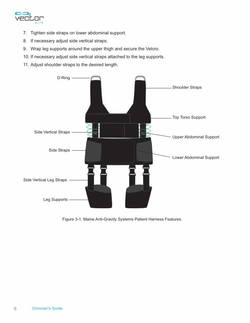
7. Tighten side straps on lower abdominal support.
8. If necessary adjust side vertical straps.
9. Wrap leg supports around the upper thigh and secure the Velcro.
10. If necessary adjust side vertical straps attached to the leg supports.
11. Adjust shoulder straps to the desired length.
Figure 3-1: Maine Anti-Gravity Systems Patient Harness Features.
Shoulder Straps
Lower Abdominal Support
Upper Abdominal Support
Top Torso Support
Side Straps
Side Vertical Straps
Side Vertical Leg Straps
Leg Supports
D-Ring
Chapter
7
Starting the Vector Elite System and Software
Turning the system on and off
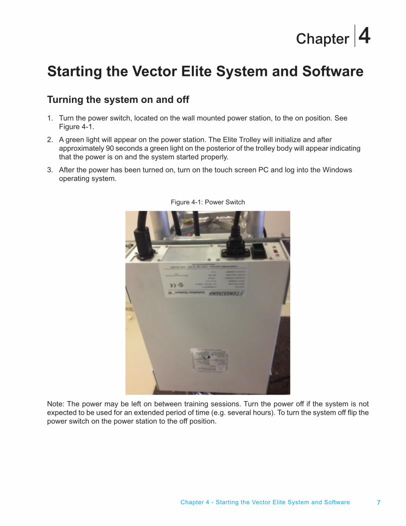
1. Turn the power switch, located on the wall mounted power station, to the on position. See Figure 4-1.
2. A green light will appear on the power station. The Elite Trolley will initialize and after approximately 90 seconds a green light on the posterior of the trolley body will appear indicating that the power is on and the system started properly.
3. After the power has been turned on, turn on the touch screen PC and log into the Windows operating system.
Figure 4-1: Power Switch
Note: The power may be left on between training sessions. Turn the power off if the system is not expected to be used for an extended period of time (e.g. several hours). To turn the system off flip the power switch on the power station to the off position.
4
Chapter 4 - Starting the Vector Elite System and Software

8 Clinician's Guide
Launching the Vector Gait and Safety Software
1. To launch the Vector Elite Software click on the icon labeled “Vector Gait and Safety System” located on the computer screen.
2. The Login screen will appear, enter in your username and password. Click on the green arrow to login and proceed to the Main Menu. See Figure 4-2.
Note: Login username will be set up when the administrator creates new user accounts.
Figure 4-2: Login Screen
3. After logging into the software the Main Menu screen will appear. See Figure 4-3. There are four menu options to choose from on the Main Menu screen:
• Patient Training Menu – This option is to access the patient database, create a new patient account and start a training session.
• Manual Control Menu – This option allows the clinician to control the Vector Elite Trolley manually without needing to select a patient account.
• Summaries Menu – This option allows the clinician to view a patient’s training history data.
• Reference Library Menu- This is the location of training videos of examples of patients using the product and of the Vector Elite Clinician’s Guide.
Note: Log-out arrow is used to return to the login screen. Use after a session has ended.
Note: You can always quit the Vector Elite software any time by simply clicking on the ‘X’ mark in the upper right hand side of the screen.

9Chapter 4 - Starting the Vector Elite System and Software
Figure 4-3: Main Menu Screen
Patient Training
Summaries
Manual Control
Reference Material Library
Log Out

10 Clinician's Guide
Chapter
11
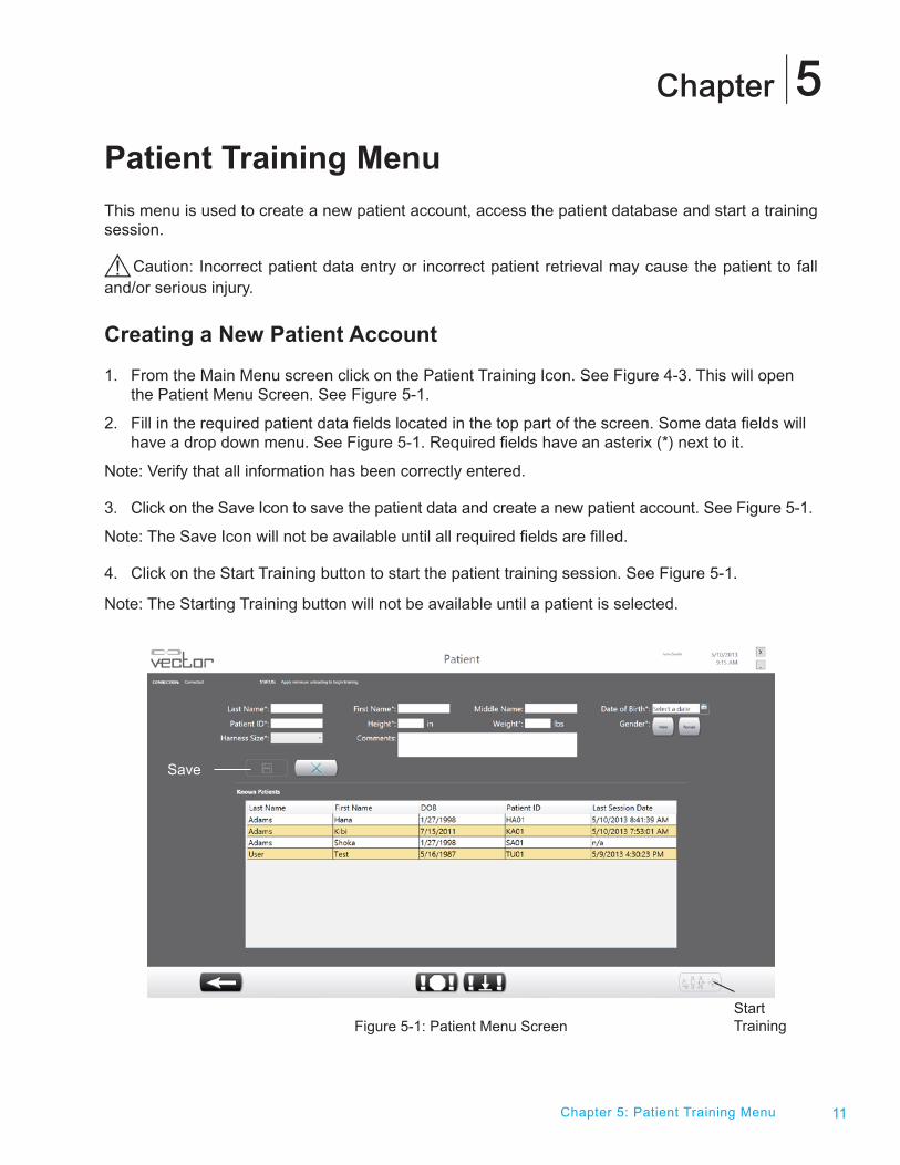
Patient Training Menu This menu is used to create a new patient account, access the patient database and start a training session.
Caution: Incorrect patient data entry or incorrect patient retrieval may cause the patient to fall and/or serious injury.
Creating a New Patient Account
1. From the Main Menu screen click on the Patient Training Icon. See Figure 4-3. This will open the Patient Menu Screen. See Figure 5-1.
2. Fill in the required patient data fields located in the top part of the screen. Some data fields will have a drop down menu. See Figure 5-1. Required fields have an asterix (*) next to it.
Note: Verify that all information has been correctly entered.
3. Click on the Save Icon to save the patient data and create a new patient account. See Figure 5-1.
Note: The Save Icon will not be available until all required fields are filled.
4. Click on the Start Training button to start the patient training session. See Figure 5-1.
Note: The Starting Training button will not be available until a patient is selected.
Figure 5-1: Patient Menu Screen
Chapter 5: Patient Training Menu
5
Save
Start Training

12 Clinician's Guide
Opening an Existing Patient Account
1. From the Main Menu screen click on the Patient Training Icon. See Figure 4-3. This will open the Patient Menu Screen.
2. The screen will display patients currently in the database under “Known Patients”.
3. Select patient from list shown on the screen by clicking on the patient’s name highlighting that row. Use the scroll up/down if there are more patients that fit in one screen or start typing in the patient’s name in the blank fields above the list. The database will filter and display only the names that match the typed information. See Figure 5-2.
4. Once the patient has been selected the data fields will automatically be filled in with the patient’s information. At this time if appropriate the patient’s information can be edited by clicking the Edit button. All patient data fields can be cleared by clicking the Clear button. See Figure 5-3.
5. Click on the Start Training Button to open the Training Session Screen. See Figure 5-3.
Figure 5-2: Filtered Patient Menu
A

13Chapter 5: Patient Training Menu
Figure 5-3: Selecting a Patient
Training Session Screen
The Training Session screen is divided into 3 sections: Manual Controls, Training Controls, and Session Status. See Figure 5-4.
Figure 5-4: Training Session Screen
Edit
Start Training
Clear

14 Clinician's Guide
Manual Controls
Warning: The Vector Elite System is not intended for patient transport. Using the system as a transport could cause serious patient injury.
When the Training Session screen opens only the Manual Controls section is enabled. See Figure 5-4. The Manual Control section allows the user to winch the rope up and down and to move the trolley along the track in either direction. See Table 5-1.
Manual Control Button Definition
When pressed this button will continue to winch up the trolley rope with spreader bar attached until the button is released.
When pressed this button will continue to winch down the trolley rope with spreader bar attached until the button is released.
When pressed this button will continue to move the trolley along the track in the direction indicated until the button is released. Reference the trolley icon to determine the direction of the movement.
When pressed this button will continue to move the trolley along the track in the direction indicated until the button is released. Reference the trolley icon to determine the direction of the movement.
When pressed this button will move the trolley 18 inches (45.7 cm) along the track in the direction indicatedand then stop. Reference the trolley icon to determine the direction of the movement.
When pressed this button will move the trolley 18 inches (45.7 cm) along the track in the direction indicated and then stop. Reference the trolley icon to determine the direction of the movement.
Table 5-1: Manual Control Button Definitions
The Manual Control buttons are used to position the trolley along the track, lower the trolley rope in order to connect the patient harness to the spreader bar, and winch up the trolley rope to the desired tension for the patient harness straps.
Attaching a Patient Harness to the Spreader Bar
After a patient harness has been securely placed and adjusted on the patient, the harness will need to be attached to the spreader bar.
1. Make sure the patient is in a secured position.
2. Use the Manual Control Winch Down button to lower the rope with spreader bar attached.
15Chapter 5: Patient Training Menu
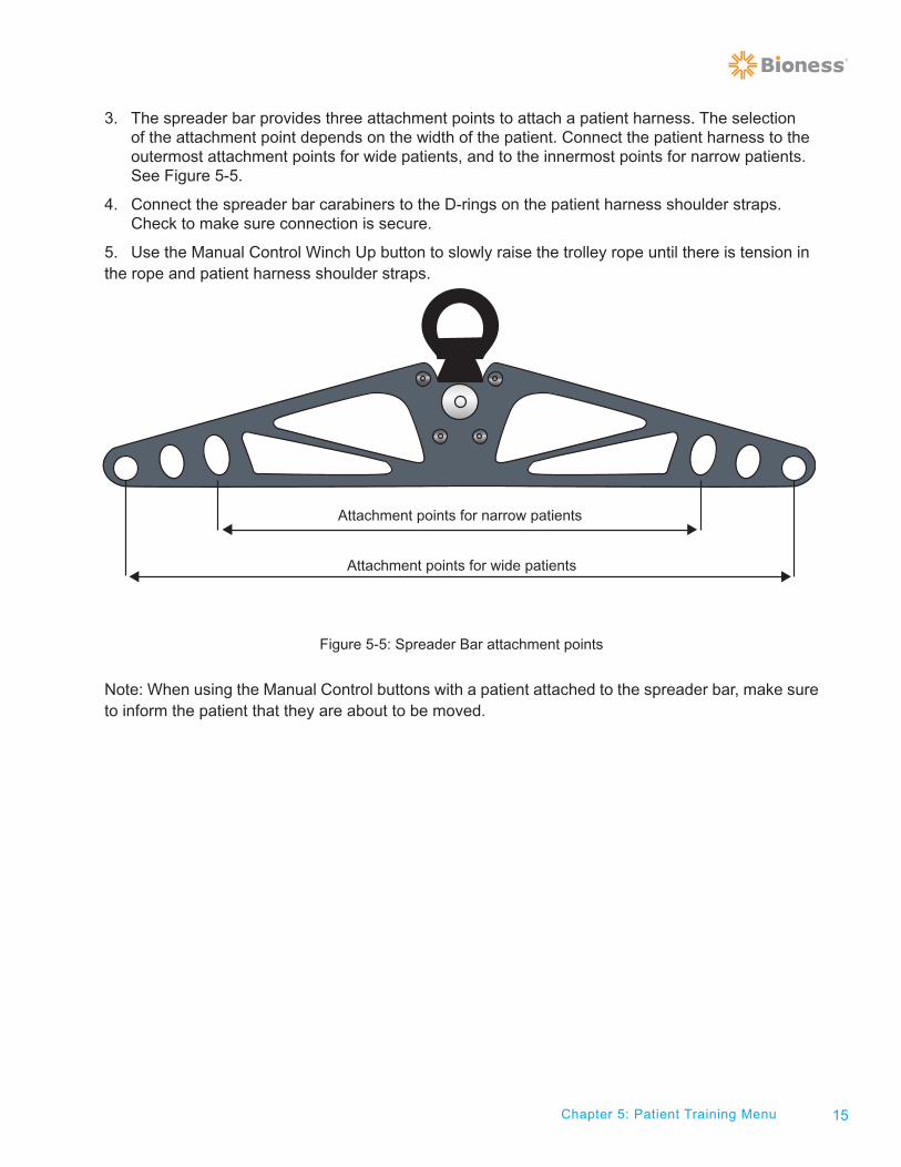
3. The spreader bar provides three attachment points to attach a patient harness. The selection of the attachment point depends on the width of the patient. Connect the patient harness to the outermost attachment points for wide patients, and to the innermost points for narrow patients. See Figure 5-5.
4. Connect the spreader bar carabiners to the D-rings on the patient harness shoulder straps. Check to make sure connection is secure.
5. Use the Manual Control Winch Up button to slowly raise the trolley rope until there is tension in the rope and patient harness shoulder straps.
Figure 5-5: Spreader Bar attachment points
Note: When using the Manual Control buttons with a patient attached to the spreader bar, make sure to inform the patient that they are about to be moved.
Attachment points for narrow patients
Attachment points for wide patients
16 Clinician's Guide
Training Controls
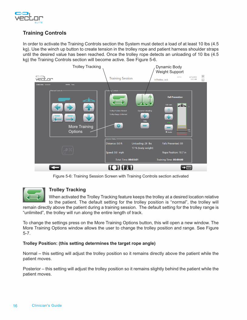
In order to activate the Training Controls section the System must detect a load of at least 10 lbs (4.5 kg). Use the winch up button to create tension in the trolley rope and patient harness shoulder straps until the desired value has been reached. Once the trolley rope detects an unloading of 10 lbs (4.5 kg) the Training Controls section will become active. See Figure 5-6.
Figure 5-6: Training Session Screen with Training Controls section activated
Trolley Tracking
When activated the Trolley Tracking feature keeps the trolley at a desired location relative to the patient. The default setting for the trolley position is “normal”, the trolley will
remain directly above the patient during a training session. The default setting for the trolley range is “unlimited”, the trolley will run along the entire length of track.
To change the settings press on the More Training Options button, this will open a new window. The More Training Options window allows the user to change the trolley position and range. See Figure 5-7.
Trolley Position: (this setting determines the target rope angle)
Normal – this setting will adjust the trolley position so it remains directly above the patient while the patient moves.
Posterior – this setting will adjust the trolley position so it remains slightly behind the patient while the patient moves.
Trolley Tracking Dynamic Body Weight Support
More Training Options

17Chapter 5: Patient Training Menu
Trolley Range:
Unlimited – this setting will allow the trolley to run along the entire length of the track.
Specified – this setting will only allow the trolley to run along a specified range on the track. Use the plus and minus buttons to adjust the range. The starting point of the range is determined when it is set. For example, if a range is set to 8 feet, trolley can move from the current location of the trolley to 8 feet in both directions.
Note: Minimum trolley range is 6 inches (15.2 cm) and maxiumum trolley range is 10 feet (3m).
Figure 5-7: More Training Options Window
Dynamic Body Weight Support (DBWS)
When activated the Dynamic Body Weight Support (DBWS) feature keeps the rope tension at a desired value. As the patient moves the trolley will make adjustments to
the rope to keep the dynamic unloading at the desired value. The amount of dynamic unloading is controlled by the plus “+” and minus “-“ buttons and is shown in pounds (kilograms) and percent of body weight. Each tap of the plus and minus buttons equals a one unit (lbs or kg) change. Holding the button allows the clinician to ramp units quickly, up or down.
Once activated the DBWS will remain on until the button has been turned off, a fall is dected or until the dynamic unloading force falls below 10 lbs (4.5 kg). This is a safety feature that ensures that if the spreader bar is released while in dynamic BWS, the system does not rapidly winch the spreader bar up and cause injury.
Dynamic Unloading
The default dynamic unloading setting is 10 lbs (4.5 kg). Dynamic unloading can be adjusted between 10 lbs (4.5 kg) to 200 lbs (90.7 kg). To change the setting use the plus or minus button and the change will appear in the text between the buttons.

18 Clinician's Guide
Fall Limit
The Fall Limit is a safety feature that prevents the patient from falling. The programmed fall limit value is the amount of descent that the patient can travel before the system locks the rope winch, deactivates trolley tracking (if enabled) and detects a fall.
The default Fall Limit setting is 4.0 inches (10.1 cm). The Fall Limit setting can be adjusted from 4.0 inches (10.1 cm) to 36 inches (91.4 cm), depending on the training activity. To adjust the setting, use the plus and minus buttons to increase the Fall Limit in increments of 1 inch (2.5 cm) and click on the Save button. The revised setting will appear in the text between the buttons. Make sure the Fall Limit value is in green color. If not, click on the Save button to ensure that the fall limit value has been set properly.
The fall limit could also be disabled for certain circumstances such as performing pre-gait activities. To disable the fall limit check the box next to the word “Disable” and press the Save button. A window will appear to confirm that the clinician wants to disable the fall limit. Press the OK button.
Caution: Extra precautions should be taken with the patient when the fall limit is disabled, due to the possibility of patient injury.
The animated graphic bar next to the fall limit visually shows how close to the Fall Limit the patient is at any given time during a training session.
Session Status Section
The Session Status section displays real-time information during a training session. See Figure 5-8. It displays the amount of weight unloaded, total session time, training time, walking speed, rope position, number of falls prevented and total distance walked during the training session.
Starting a Training Session
Note: During a training session a clinician should stay by the PC computer in order to operate the Vector Elite System software controls. Another clinician/assistant should stay by the patient to ensure their safety during the session.
1. At a start of a training session the dynamic unloading amount will be the default setting of 10 lbs (4.5 kg). To adjust the dynamic unloading value, use the plus and minus buttons. The revised value will display in the text between the buttons.
2. At a start of a training session the fall limit value will be the default setting of 4.0 inches (10.1 cm). If necessary adjust the fall limit value using the plus and minus buttons. Then press the save button to save the revised value, which will display in the text between the buttons.
3. To activate the Trolley Tracking, apply at least 10 lbs (4.5 kg) of load and press the button. The Trolley Tracking button will go from green to red indicating that the feature is turned on. See Figure 5-8.
Note: The Trolley Tracking feature should be activated if the patient is practicing over-ground walking. It is suggested not to activate the Trolley Tracking feature for certain exercise activities such as deep knee bends and sit-to-stand activities.
19
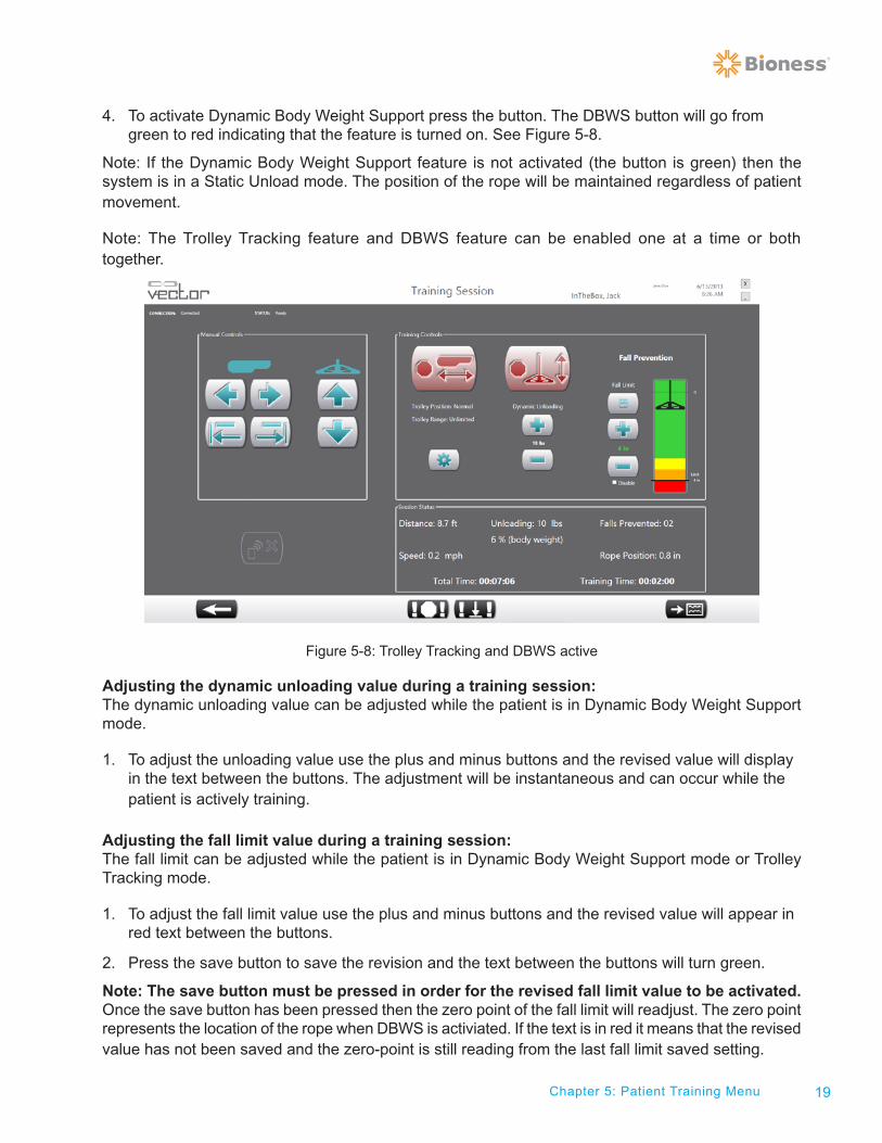
4. To activate Dynamic Body Weight Support press the button. The DBWS button will go from green to red indicating that the feature is turned on. See Figure 5-8.
Note: If the Dynamic Body Weight Support feature is not activated (the button is green) then the system is in a Static Unload mode. The position of the rope will be maintained regardless of patient movement.
Note: The Trolley Tracking feature and DBWS feature can be enabled one at a time or both together.
Figure 5-8: Trolley Tracking and DBWS active
Adjusting the dynamic unloading value during a training session:The dynamic unloading value can be adjusted while the patient is in Dynamic Body Weight Support mode.
1. To adjust the unloading value use the plus and minus buttons and the revised value will display in the text between the buttons. The adjustment will be instantaneous and can occur while the patient is actively training.
Adjusting the fall limit value during a training session: The fall limit can be adjusted while the patient is in Dynamic Body Weight Support mode or Trolley Tracking mode.
1. To adjust the fall limit value use the plus and minus buttons and the revised value will appear in red text between the buttons.
2. Press the save button to save the revision and the text between the buttons will turn green.
Note: The save button must be pressed in order for the revised fall limit value to be activated. Once the save button has been pressed then the zero point of the fall limit will readjust. The zero point represents the location of the rope when DBWS is activiated. If the text is in red it means that the revised value has not been saved and the zero-point is still reading from the last fall limit saved setting.
Chapter 5: Patient Training Menu

20 Clinician's Guide
Note: It is suggested that at the start of each exercise that the save button is pressed to ensure that the zero-point of the fall limit value has been readjusted.
Figure 5-9: Training Session Screen
Fall Limit Detection
During a training session the Vector Elite System will detect and prevent a fall when the fall distance from the zero point is greater than the set Fall Limit value. When the system detects and prevents a fall the trolley is locked and placed into Static Unload mode.
1. Vector Elite System detects a fall and the Fall Prevented window appears in the software. See Figure 5-10.
2. Press the Manual Controls winch up button to help the patient regain control, so they are in a standing position. Or if necessary use the Emergency Lower button to lower the patient to the ground.
3. Close the Fall Prevented window and if the patient is in a standing position press the Dynamic Body Weight Support button and (if applicable) the Trolley Tracking button to resume the training session.
Previous Screen Emergency LowerEmergency Stop Session Summary Screen

21Chapter 5: Patient Training Menu
Figure 5-10: Fall Prevented Window
Stopping a Training Session
To stop a training session both the DBWS feature and the Trolley Tracking feature must be turned off, both buttons need to be green. See Figure 5-9. If the Previous Screen Button (See Figure 5-9) is pressed, this will also end a training session. Once a training session is ended the fall limit setting and dynamic unloading setting will go back to the default value.
Emergency Stop and Emergency Lower Buttons
At the bottom of the training session screen are the Emergency Stop and Emergency Lower buttons. See Figure 5-9. At any given time these buttons can be used for emergency situations.
Emergency Stop Button
When the Emergency Stop Button is pressed the trolley stops moving and is in a locked position. The system is in Static Unload mode.
Emergency Lower Button
If a patient becomes medically unstable the Emergency Lower Button can be pressed. Once pressed the system will continue to winch down the rope, with controlled velocity, until the patient has reached the ground or until the dynamic unload force goes below the default value.

22 Clinician's Guide
Session Summary Screen
The Session Summary screen shows plots of the key session parameters that were captured during a patient training session.
1. From the Training Session Screen press the Session Summary Screen button. See Figure 5-9.
2. The Session Summary Screen will open in the Current Session Screen. See Figure 5-11. The Current Session Screen shows information, as a line graph, for the patient session in progress.
3. Press the All Sessions Button to switch to the All Sessions screen. See Figure 5-12. This screen shows a summary, as bar graphs, of all training sessions for the active patient.
4. Press the Previous Screen Button (See Figure 5-11) to return to the Training Session Screen.
Figure 5-11: Session Summary Screen with Current Session Screen active
Previous Screen
All SessionsCurrent Session

23Chapter 5: Patient Training Menu
Figure 5-12: Session Summary Screen with All Sessions Screen active
Vector Elite Time Out Feature
If the Software detects no activity for 15 minutes, the system will log out and the motors will power off. A window will appear on the PC notifying the user that the System has timed out. See Figure 5-13. The clinician will need to press the check box on the Warning dialog and then log back in, to use the Vector Elite System.
Figure 5-13: Vector Time Out Window

24 Clinician's Guide

Chapter
25
Manual Control, Summaries, and Reference Material Menus The Manual Control, Summaries, and Reference Material Library Menus can be accessed from the Main Menu Screen. See Figure 6-1.
Figure 6-1: Main Menu Screen
Manual Control Menu
From the Main Menu Screen press the Manual Control Button (See Figure 6-1) to open the Manual Control Menu. This menu allows the operator to control the trolley manually without needing to select a patient from the patient database. See Figure 6-2. The Manual Control menu should be used for product demo and moving the trolley when the user does not need to capture any data.
Manual Control Button Definition
When pressed this button will continue to winch up the trolley rope with spreader bar attached until the button is released.
When pressed this button will continue to winch down the trolley rope with spreader bar attached until the button is released.
When pressed this button will continue to move the trolley along the track in the direction indicated until the button is released. Reference the trolley icon to determine the direction of the movement.
Chapter 6: Manual Control, Summaries, and Reference Material Menus
6
Patient Training
Summaries
Manual Control
Reference Material Library

26 Clinician's Guide
When pressed this button will continue to move the trolley along the track in the direction indicated until the button is released. Reference the trolley icon to determine the direction of the movement.
When pressed this button will move the trolley 18 inches (45.7 cm) along the track in the direction indicated, with a single press of a button. Reference the trolley icon to determine the direction of the movement.
When pressed this button will move the trolley 18 inches (45.7 cm) along the track in the direction indicated, with a single press of a button. Reference the trolley icon to determine the direction of the movement.
Table 6-1: Manual Control Button Definitions
Figure 6-2: Manual Control Menu
Patient Summaries Menu
From the Main Menu Screen press the Summaries Menu Button (See Figure 6-1) to open the Patient Summaries Menu Screen. This menu allows the clinician to view the training sessions of any given patient.
1. Select a patient from the “Known Patients” list, by clicking on the name. See Figure 6-3.
2. Once a patient has been selected a list of their training sessions will appear in the “Sessions” list. See Figure 6-3.
3. To view data from a single training session select the session date from the “Sessions” list and press the Single Session Button. See Figure 6-3.

27Chapter 6: Manual Control, Summaries, and Reference Material Menus
Figure 6-3: Patient Summaries Menu Screen
4. A new window will appear displaying data from that training session as a line graph. See Figure 6-4. To return to the Patient Summaries Menu Screen press the back button.
Figure 6-4: Single Session Screen
Training HistorySingle Session
Back

28 Clinician's Guide
5. From the Patient Summaries Menu Screen select a patient and press on the Training History button. This screen will show the key parameters (as bar graphs) from multiple sessions for the selected patient. See Figure 6-5.
Figure 6-5: Training History Screen
The Single Session and Training History Screens have several buttons on the bottom of the screen. These buttons allow the user to return to the training session, return to the patient database, export session data to a CSV file (which is stored on the PC hard drive), return to the main menu, and log out of the system.
Back Export Log OutMain MenuPatientDatabase

29Chapter 6: Manual Control, Summaries, and Reference Material Menus
Reference Material Library Menu
From the Main Menu Screen press the Reference Material Library Menu Button (See Figure 6-1) to open the Reference Material Library Menu Screen (See Figure 6-6).
Figure 6-6: Reference Material Library Menu Screen
Press the Training Videos button to access a folder where various training videos are stored. Press the Instruction Guides Button to access a folder where pdf files of system instructions including a electronic version of this guide are stored.
Training VideosInstruction Guides

30 Clinician's Guide

Chapter
31Chapter 7 - Vector Elite Remote Control
Vector Elite Remote Control The Remote Control has a large subset of the PC capabilities. The Remote Control is a Samsung Galaxy S3 (or equivalent) with Vector Elite software application. The Remote Control is an accessory device and is not required to operate the System, but does provide convience for the clinician. During a training session the remote control allows the clinician to operate the Vector Elite System, while being able to be next to the patient.
Note: The remote control has not been evaluated by UL and therefore is not covered under the UL Classification of the system.
Remote Control Software Navigation
Starting the Vector Elite Remote Control
1. Turn on the Vector Elite Remote Control.
2. To start the Vector Elite Software, press the Vector Elite Software application icon on the home screen. See Figure 7-1.
Figure 7-1: Starting the Remote Control Software Application
7
Software Application Icon
32 Clinician's Guide
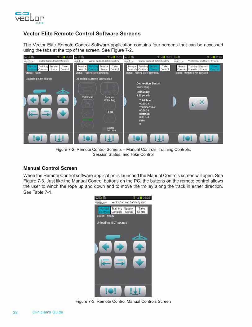
Vector Elite Remote Control Software Screens
The Vector Elite Remote Control Software application contains four screens that can be accessed using the tabs at the top of the screen. See Figure 7-2.
Figure 7-2: Remote Control Screens – Manual Controls, Training Controls, Session Status, and Take Control
Manual Control Screen
When the Remote Control software application is launched the Manual Controls screen will open. See Figure 7-3. Just like the Manual Control buttons on the PC, the buttons on the remote control allows the user to winch the rope up and down and to move the trolley along the track in either direction. See Table 7-1.
Figure 7-3: Remote Control Manual Controls Screen

33Chapter 7 - Vector Elite Remote Control
Manual Control Button Definition
When pressed this button will continue to winch up the trolley rope with spreader bar attached until the button is released.
When pressed this button will continue to winch down the trolley rope with spreader bar attached until the button is released.
When pressed this button will continue to move the trolley along the track in the direction indicated until the button is released. Reference the trolley icon to determine the direction of the movement.
When pressed this button will continue to move the trolley along the track in the direction indicated until the button is released. Reference the trolley icon to determine the direction of the movement.
When pressed this button will move the trolley 18 inches (45.7 cm) along the track in the direction indicated, with a single press of a button. Reference the trolley icon to determine the direction of the movement.
When pressed this button will move the trolley 18 inches (45.7 cm) along the track in the direction indicated, with a single press of a button. Reference the trolley icon to determine the direction of the movement.
Table 7-1: Remote Control Manual Control Button Definitions
Training Controls Screen
The Training Controls Screen allows the user to activate and de-active the Trolley Tracking and Dynamic Body Weight Support features. See Figure 7-4.
Figure 7-4: Remote Control Training Controls Screen
Trolley TrackingDynamic Body Weight Support

34 Clinician's Guide
Adjusting the dynamic unloading value during a training session:The dynamic unloading value can be adjusted while the patient is in Dynamic Body Weight Support mode.
1. To adjust the dynamic unloading value, use the up arrow button to increase the amount and the down arrow button to decrease. The revised value will display in the text between the buttons. The adjustment will be instantaneous.
Adjusting the fall limit value during a training session: The fall limit can be adjusted while the patient is in Dynamic Body Weight Support mode or Trolley Tracking mode.
1. To adjust the fall limit value, use the up arrow button to increase the amount and the down arrow button to decrease. The revised value will appear in red text between the buttons.
2. Press the save button to save the revised value and the text between the buttons will turn green.
Note: The save button must be pressed in order for the revised fall limit value to be activated. Once the save button has been pressed then the zero point of the fall limit will readjust. If the text is in red it means that the revised value has not been saved and the zero-point is still reading from the last fall limit saved setting.
Disabling the Fall LimitThe fall limit can also be disabled from the remote control.
1. Check the “Disable Fall Limit” box.
2. Press the Save button.
3. A window will appear to confirm that the clinician wants to disable the fall limit. Press OK.
Caution: Extra precautions should be taken with the patient when the fall limit is disabled, due to the possibility of patient injury.
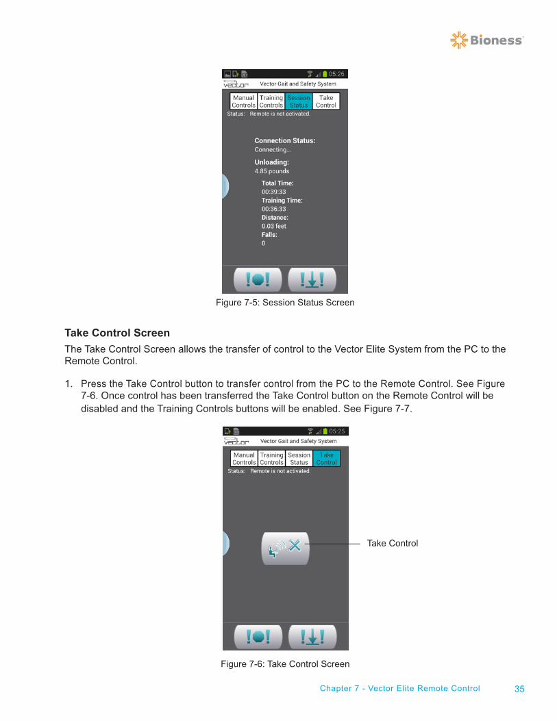
Session Status Screen
The Session Status Screen displays the following information the unloading value, training time of session, distance traveled, and number of prevented falls. The data that is shown on this screen is for the current training session only; it does not show a summary of sessions for that patient.
35Chapter 7 - Vector Elite Remote Control
Figure 7-5: Session Status Screen
Take Control Screen
The Take Control Screen allows the transfer of control to the Vector Elite System from the PC to the Remote Control.
1. Press the Take Control button to transfer control from the PC to the Remote Control. See Figure 7-6. Once control has been transferred the Take Control button on the Remote Control will be disabled and the Training Controls buttons will be enabled. See Figure 7-7.
Figure 7-6: Take Control Screen
Take Control

36 Clinician's Guide
Controlling Device Status
Only one device (PC or Remote Control) can be in control of the Vector Elite System at any given time. This is a safety feature designed to prevent potentially conflicting commands from being issued by different clinicians on separate devices. Both devices display on the screens whether they are or are not in control. To ensure that only one device is in control, the buttons on the device will only be active/enabled if that device is in control. See Figure 7-7.
Figure 7-7: Example of Status Displays for Remote Control
(Left) Remote is not in control of Trolley, (Right) Remote is in control of Trolley
In order to transfer control from one device to the other, the non controlling device must take control by pressing the Take Control button. The exception to this rule is the fact that the Emergency Stop and Emergency Lower buttons are enabled on both devices at all times.
If the controlling device loses communication with the Trolley, the Trolley will automatically transfer control to the other device. For example, if the Remote Control battery dies while in use, the Trolley will automatically transfer control to the PC. If both the PC and the Remote Control lose communication with the Trolley, then the Trolley enters a safe state where both motors stop moving until a recognized device is in control again.

37Chapter 7 - Vector Elite Remote Control
Using the Remote Control for a Patient Training Session
A patient training session has to always be started from the PC in order for the Vector Elite System to capture patient data.
1. Select a patient from the Patient Menu Screen. See “Patient Training Menu” section of this guide.
2. Press the Start Training Button to open the Training Session Screen. See “ Training Session Screen” section of this guide.
3. Turn on the Remote Control, press the Take Control tab.
4. To transfer system control from the PC to the Remote Control, press the Take Control button from the Remote Control. See Figure 7-8.
5. Once the Remote Control establishes connection with the Trolley the status display will state “Ready”.
6. Press the Training Controls tab. See Figure 7-9
7. If needed adjust Dynamic Unloading and Fall Limit settings.
8. Press the Trolley Tracking and/or Dynamic Body Weight Support buttons to start patient training session.
Figure 7-8: Take Control Button on the Remote Control
Take Control

38 Clinician's Guide
Figure 7-9: Training Controls Screen
Emergency Stop and Emergency Lower
At any time the Emergency Stop or the Emergency Lower button can be pressed from the Remote Control. See Figure 7-9. When the Emergency Stop Button is pressed the trolley stops moving and is in a locked position. The system is in Static Unload mode. When the Emergency Lower Button is pressed the system will continue to winch down the rope until the patient has reached the ground or until the dynamic unload force goes below the minimum unload value.
Using the Remote Control to Operate System without Patient Data
When turning on the Vector Elite System if the Remote Control establishes a connection with the trolley before the PC does then any training data will not be saved. A patient account must be selected in order for training data to be saved to a session summary.
For certain circumstances the user will want to control the Vector Elite System without capturing training data.
1. Connect the Remote Control to the Vector Elite Trolley.
2. If the Trolley Tracking and/or Dynamic Body Weight Support buttons are pressed, without the PC establishing connection to the trolley, then a warning box stating that “Data is not being saved” will appear. Press the OK button to proceed with using the Remote Control.
Charging the Remote Control
The Remote Control should be charged daily. It is shipped with a AC adaptor and micro USB cable for charging.
Trolley TrackingDynamic Body Weight Support
Emergency Stop Emergency Lower

Chapter
39Chapter 8 - Vector Elite Software Administrator Menu
Vector Elite Software Administrator Menu The administrator has a higher level of privileges within the Vector Elite software. Administrator privileges include:
• Managing the Patient Database
• Managing User Accounts (create and close accounts)
• Data Backup and Restore
• Troubleshooting
• System Settings
Accessing the Administrator Menu
1. Log In to the Vector Elite Software with an Administrator log in. See Figure 8-1.
2. The Main Menu Screen will open. Press the Admin Mode Button. See Figure 8-2.
3. The Administration Screen will open. See Figure 8-3.
Figure 8-1: Log In Screen
8

40 Clinician's Guide
Figure 8-2: Admin Mode Button
Figure 8-3: Administrator Menu Screen
Admin Mode
Backup and Restore
PatientDatabase
Add User
System SettingsTroubleshooting

41Chapter 8 - Vector Elite Software Administrator Menu
Administration Menu
Patient Database
The Patient Database is used to manage patient records.
1. From the Administrator Menu Screen press on the Patient Database button. See Figure 8-3.
2. This will open the Manage Patients Screen. See Figure 8-4.
3. Select patient from list and if applicable click on the edit button.
4. Press the Exit button to return to the Administration Menu screen.
Figure 8-4: Manage Patient Records Screen
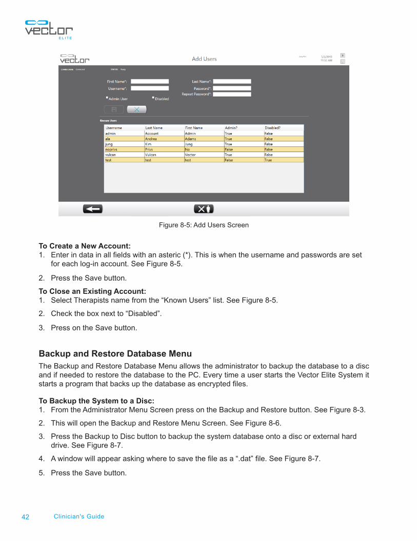
Add User
The Add User Screen allows the administrator to create, edit, and close clinician accounts.
1. Press on the Account Management button. See Figure 8-3.
2. This will open the Add Users Screen. See Figure 8-5.
Exit
42 Clinician's Guide
Figure 8-5: Add Users Screen
To Create a New Account:1. Enter in data in all fields with an asteric (*). This is when the username and passwords are set for each log-in account. See Figure 8-5.
2. Press the Save button.
To Close an Existing Account:1. Select Therapists name from the “Known Users” list. See Figure 8-5.
2. Check the box next to “Disabled”.
3. Press on the Save button.
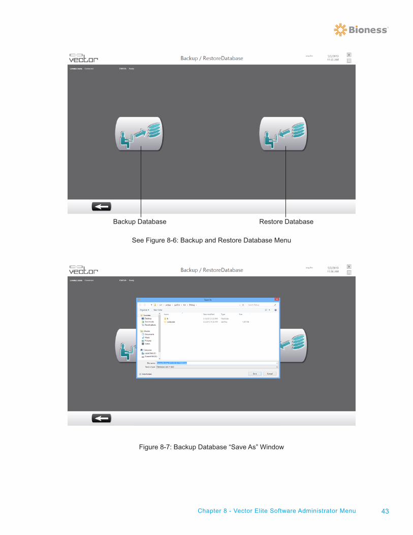
Backup and Restore Database MenuThe Backup and Restore Database Menu allows the administrator to backup the database to a disc and if needed to restore the database to the PC. Every time a user starts the Vector Elite System it starts a program that backs up the database as encrypted files.
To Backup the System to a Disc:1. From the Administrator Menu Screen press on the Backup and Restore button. See Figure 8-3.
2. This will open the Backup and Restore Menu Screen. See Figure 8-6.
3. Press the Backup to Disc button to backup the system database onto a disc or external hard drive. See Figure 8-7.
4. A window will appear asking where to save the file as a “.dat” file. See Figure 8-7.
5. Press the Save button.
43Chapter 8 - Vector Elite Software Administrator Menu
See Figure 8-6: Backup and Restore Database Menu
Figure 8-7: Backup Database “Save As” Window
Backup Database Restore Database

44 Clinician's Guide
To Restore the Database to the PC:1. From the Backup and Restore Database Menu Screen, press the Restore Database button. See Figure 8-6.
2. A window will appear, search for file and press Open button. See Figure 8-8.
Figure 8-8: Restore Databse
Troubleshooting MenuThe troubleshooting menu displays frequently asked troubleshooting topics with solutions.
System Settings MenuThe System Settings Menu is used by the administrator to change language settings, measurement units, and will state which version of software is installed. To change the language settings, select the language from the drop-down menu and press the save button.

Chapter
45Chapter 9 - Service and Maintenance
Service and Maintenance
Routine maintenance is critical for the safety and effectiveness of this device.
Check the following items before each use of the Vector Elite System:
• Inspect the rope. If the rope is worn, frayed or damaged call Bioness for a service appointment to replace the rope.
• Inspect the rope tail to make sure it is visible, see Figure 9-1. If it is not visible then the rope knot has been compromised, call Bioness for a service appointment.
• Inspect the patient harness for tears, material separation and Velcro degradation.
• Inspect the spreader bar before each use.
• Inspect the carabiners before each use.
Figure 9-1: Rope Tail
Inspect the mechanical track quarterly. Clean debris and/or dirt when necessary, using a cloth.
Items to be inspected and maintained on an annual basis:
• Visually inspect the trolley wheels for wear.
• Replace the rope connecting the trolley to the spreader bar annually. Call Bioness for a service appointment.
9
Rope Tail

46 Clinician's Guide

Chapter
47Chapter 10 - Technical Specifications
Technical Specifications
Vector Elite System Technical Specifications
Trolley Dimensions 36 inches (91.4 cm) long, 25 inches (63.5 cm)wide, and 11 inches (27.9 cm) tall
Trolley Material Cover is ABS V0 plastic, base is Aluminum grade 60601-T6
Trolley Patient Weight Limit 400 lbs (181.4 kg)
Trolley Rope Material 8mm diameter HMPE (High Modulus Polyethylene)
Spreader Bar Material Anodized Aluminum
Environmental conditions for operation Temperature Range :15C to 35CAtmospheric Pressure Range: up to 80kPaRelative Humidity range: 20% to 60%.
Environmental conditions for transport and storage
Temperature Range :-25C to 70CAtmospheric Pressure Range: up to 67kPaRelative Humidity range: 5% to 95%
The system consists of mechanical and electronic components. Inadequate handling of those components may cause health hazards. Disposal of the system must comply with local regulations.
10