bioprocessing & pharmaceutical - parker...
TRANSCRIPT

Bioprocessing & PharmaceuticalProduct Catalogue

This document is available in ELECTRONIC FORMAT ONLY.
Parker domnick hunter have a continuous environment policy.

filtration sensorsautomated systems
Parker Hannifin Manufacturing Ltd
domnick hunter Process Filtration - EuropeDurham RoadBirtley, Co. DurhamDH3 2SF, Englandphone +44 (0)191 4105121fax +44 (0)191 4105312email: [email protected]/dhpharma
Parker Hannifin Corporation
domnick hunter Process Filtration - North America2340 Eastman Avenue,Oxnard, California, USA 93030toll free: 877 784 2234phone: +1 805 604 3400fax: +1 608 824 0509email: [email protected]/dhpharma
Contents
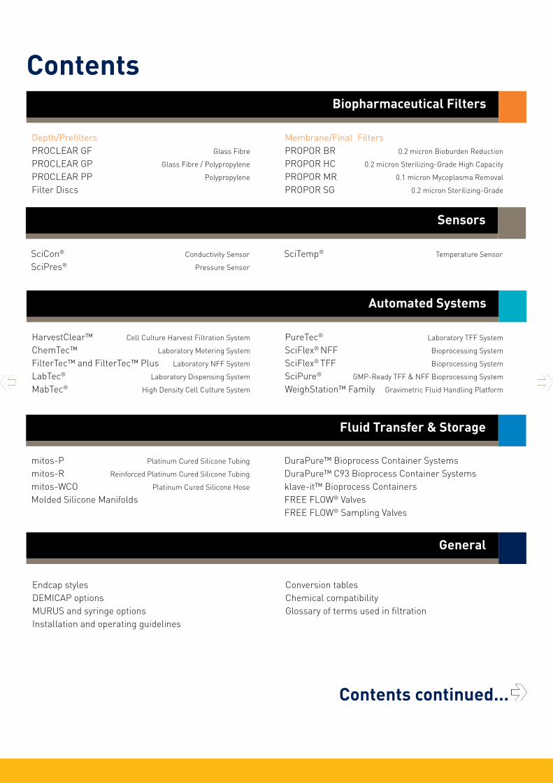
Fluid Transfer & Storage
mitos-P Platinum Cured Silicone Tubing
mitos-R Reinforced Platinum Cured Silicone Tubing
mitos-WCO Platinum Cured Silicone Hose
Molded Silicone Manifolds
DuraPure™ Bioprocess Container SystemsDuraPure™ C93 Bioprocess Container Systemsklave-it™ Bioprocess ContainersFREE FLOW® ValvesFREE FLOW® Sampling Valves
Depth/PrefiltersPROCLEAR GF Glass Fibre
PROCLEAR GP Glass Fibre / Polypropylene
PROCLEAR PP Polypropylene
Filter Discs
Membrane/Final FiltersPROPOR BR 0.2 micron Bioburden Reduction
PROPOR HC 0.2 micron Sterilizing-Grade High Capacity
PROPOR MR 0.1 micron Mycoplasma Removal
PROPOR SG 0.2 micron Sterilizing-Grade
Biopharmaceutical Filters
HarvestClear™ Cell Culture Harvest Filtration System
ChemTec™ Laboratory Metering System
FilterTec™ and FilterTec™ Plus Laboratory NFF System
LabTec® Laboratory Dispensing System
MabTec® High Density Cell Culture System
PureTec® Laboratory TFF System
SciFlex® NFF Bioprocessing System
SciFlex® TFF Bioprocessing System
SciPure® GMP-Ready TFF & NFF Bioprocessing System
WeighStation™ Family Gravimetric Fluid Handling Platform
Automated Systems
SciCon® Conductivity Sensor
SciPres® Pressure Sensor
SciTemp® Temperature Sensor
Sensors
General
Endcap stylesDEMICAP optionsMURUS and syringe optionsInstallation and operating guidelines
Conversion tablesChemical compatibilityGlossary of terms used in filtration
Contents continued...
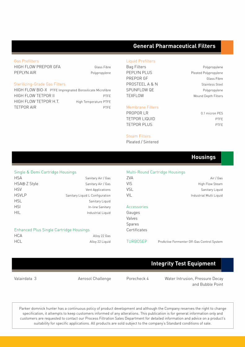
Valairdata 3 Aerosol Challenge Porecheck 4 Water Intrusion, Pressure Decay and Bubble Point
Integrity Test Equipment
Single & Demi Cartridge HousingsHSA Sanitary Air / Gas
HSA⊕ Z Style Sanitary Air / Gas
HSV Vent Applications
HSVLP Sanitary Liquid L Configuration
HSL Sanitary Liquid
HSI In-line Sanitary
HIL Industrial Liquid
Enhanced Plus Single Cartridge HousingsHCA Alloy 22 Gas
HCL Alloy 22 Liquid
Multi-Round Cartridge HousingsZVA Air / Gas
VIS High Flow Steam
VSL Sanitary Liquid
VIL Industrial Multi Liquid
AccessoriesGaugesValvesSparesCertificates
TURBOSEP ProActive Fermenter Off-Gas Control System
Housings
Parker domnick hunter has a continuous policy of product development and although the Company reserves the right to change specification, it attempts to keep customers informed of any alterations. This publication is for general information only and
customers are requested to contact our Process Filtration Sales Department for detailed information and advice on a product’s suitability for specific applications. All products are sold subject to the company’s Standard conditions of sale.
Gas PrefiltersHIGH FLOW PREPOR GFA Glass Fibre
PEPLYN AIR Polypropylene
Sterilizing-Grade Gas FiltersHIGH FLOW BIO-X PTFE Impregnated Borosilicate Microfibre
HIGH FLOW TETPOR II PTFE
HIGH FLOW TETPOR H.T. High Temperature PTFE
TETPOR AIR PTFE
Liquid PrefiltersBag Filters Polypropylene
PEPLYN PLUS Pleated Polypropylene
PREPOR GF Glass Fibre
PROSTEEL A & N Stainless Steel
SPUNFLOW QE Polypropylene
TEXFLOW Wound Depth Filters
Membrane FiltersPROPOR LR 0.1 micron PES
TETPOR LIQUID PTFE
TETPOR PLUS PTFE
Steam FiltersPleated / Sintered
General Pharmaceutical Filters

PROCLEAR GF filters are designed for reliable and economical removal of particulate and microorganisms from pharmaceutical fluids.
The non-fibre releasing glass microfibre filter media gives excellent dirt holding capacity and high flow rates for long service life and efficient and cost-effective filter system design.
PROCLEAR GF filters have low extractable levels making them ideal for general clarification and prefiltration duties in pharmaceutical processing.
Features and Benefits
• Excellent dirt holding capacity
• Non-fibre releasing glass microfibre media
• Long service life for maximum throughput
• MURUS and DEMICAPs can be gamma-irradiated and autoclaved
Performance Characteristics
PROCLEAR GF Filters
• liquid filters• glass microfibre
Note: PROCLEAR and DEMICAP are registered trademarks of Parker Hannifin Corporation.
10¨ size (250 mm) Cartridge
60
50
40
30
20
10
0
Diff
eren
tial
Pre
ssur
e (m
bar)
0.8
0.6
0.4
0.2
0
Diff
eren
tial
Pre
ssur
e (p
si)
0 10 20 30
Flow (L / min) for liquid @ 20 °C and 1 cp
Flow (gpm (US))0 2 4 6 8
B size (65 mm) Cartridge and Capsule
90
80
70
60
50
40
30
20
10
0
Diff
eren
tial
Pre
ssur
e (m
bar)
1.2
1.0
0.8
0.6
0.4
0.2
0
Diff
eren
tial
Pre
ssur
e (p
si)
0 2 4 6 8 10
Flow (L / min) for liquid @ 20 °C and 1 cp
Flow (gpm (US))0 0.5 1.0 1.5 2.0 2.5
2.0 µm
5.0 µm
10.0 µm
7.0 µm
1.0 µm
0.6 µm
For K size for a given flow rate multiply 10¨ size differential pressure by 2 For A size for a given flow rate divide B size differential pressure by 2For E size for a given flow rate multiply B size differential pressure by 2
2.0 µm
5.0 µm
10.0 µm
7.0 µm
1.0 µm
0.6 µm

SpecificationsMaterials of Construction Filtration Media: Glass Microfibre Upstream Support: Polypropylene Downstream Support: Polypropylene
Filter Cartridges Inner Support Core: Polypropylene Outer Protection Cage: Polypropylene End Caps: Polypropylene End Caps Insert: 316L Stainless Steel *Not available in B & L endcap variants
MURUS Disposable Filter Capsules Core: Polypropylene Sleeve: Polypropylene End Caps Insert: 316L Stainless Steel Standard o-rings/gaskets: Silicone Capsule Body: Polypropylene Capsules Vent Seals: Silicone
DEMICAP Filter Capsules Core: Polypropylene Sleeve: Polypropylene Capsule Body: Polypropylene Capsules Vent Seals: Silicone Filling Bell: Polycarbonate
Syringe Filters Body: Polypropylene
Recommended Operating ConditionsFilter CartridgesUp to 70 °C (158 °F) continuous operating temperature and higher short-term temperatures during CIP to the following limits:
MURUS Disposable Filter CapsulesUp to 25 °C ( 77 °F) @ 5.5 barg (79.7 psig)Up to 60 °C (140 °F) @ 2.8 barg (40.6 psig)
Parker Hannifin certify that this product complies with the European Council Pressure Equipment Directive (PED) 97/23/EC Article 3, Paragraph 3 - Sound Engineering Practice (SEP). This product is intended for use with Group 1 & 2 Dangerous and Harmless Liquids and Group 2 Harmless Gases at the operating conditions stated in this document : In compliance with PED Article 3, Paragraph 3, SEP, this product does not bear the CE mark.
DEMICAP Filter CapsulesUp to 40 °C (104 °F) at line pressures up to 5.0 barg (72 psig).
Effective Filtration Area (EFA)10¨ (250 mm): 0.56 m2 (6.0 ft2)K Size: 0.27 m2 (2.9 ft2)A Size: 0.20 m2 (2.2 ft2)B Size: 0.10 m2 (1.1 ft2)E Size: 0.05 m2 (0.6 ft2)Syringe ø50 mm: 14.50 cm2 (2.25 in2)
Sterilization
PROCLEAR GF filter cartridges can be sanitized with hot water at up to 90 °C (194 °F) and are compatible with a wide range of chemicals.
For detailed operational procedures and advice on cleaning and sterilization, please contact the Technical Support Group through your usual Parker domnick hunter contact. Biological SafetyMaterials conform to the relevant requirements of 21CFR Part 177 and current USP Plastics Class VI - 121 °C and ISO10993 equivalents.
Quality StandardsPharmaceutical grade products are manufactured in accordance with cGMP, 100% flushed with pharmaceutical grade purified water.
Gamma-IrradiationPROCLEAR GF MURUS & DEMICAP disposable filters can be gamma-irradiated up to a maximum dosage of 40 kGy.
Temperature Max. Forward dP °C °F (bar) (psi)
20 68 5.0 72.5
40 104 4.0 58.0
60 140 3.0 43.5
80 176 2.0 29.0
90 194 1.5 21.7
PROCLEAR GF Filters
Autoclave Steam-in-Place Cycles Temp Cycles Temp (30 min.)
Cartridges 10 130 °C (266 °F) 10 121 °C (249.8 °F)
MURUS 5 130 °C (266 °F) - -
DEMICAP 10 130 °C (266 °F) - -
Syringe 1 130 °C (266 °F) - -

Performance CharacteristicsTOC / ConductivityThe filtrate quality from a 10¨ (250 mm) PROCLEAR GF conforms to the requirements of current USP <643> (TOC) and USP <645> (conductivity) within the first 200 ml flush of purified water.
EndotoxinsAqueous extracts from the 10¨ (250 mm) PROCLEAR GF contain < 0.25 EU / ml when tested in accordance with the Limulus Amoebocyte Lysate test.
Non-Volatile Extractables (NVE)Total NVEs extracted in the first 5 litre flush of purified water for a 10¨ (250 mm)cartridge are <10 mg.
Total NVEs extracted in the first 5 litre flush of purified water for an A size 7.9¨ (200 mm) DEMICAP capsule are <5 mg.
Pharmaceutical ValidationA full validation guide is available upon request from Laboratory Services Group (LSG).
Oxidizable SubstancesPROCLEAR GF filter cartridges meet current USP and EP quality standards for sterile purified water for oxidizable substances following a <1 litre water flush.
PROCLEAR GF Filters

PROCLEAR GF Filters
Ordering Information
PCGF - -
Code ǀ Length (Nominal)
B* 2.5¨ (65 mm)A* 5¨ (125 mm)K 5¨ (125 mm)1 10¨ (250 mm)2 20¨ (500 mm)3 30¨ (750 mm)4 40¨ (1000 mm)
Code ǀ Micron
96 0.6 µm01 1.0 µm02 2.0 µm05 5.0 µm07 7.0 µm10 10.0 µm
Code ǀ Variant
P Pharmaceutical
Code ǀ O-rings
E EPDMP PTFE Encapsulated SiliconeS SiliconeV Viton
PLGF -
Code ǀ Length (Nominal)
K 5¨ (125 mm)1 10¨ (250 mm)2 20¨ (500 mm)3 30¨ (750 mm)
Code ǀ Micron
96 0.6 µm01 1.0 µm02 2.0 µm05 5.0 µm07 7.0 µm10 10.0 µm
Code ǀ Inlet Connection
A 3/4¨ Tri-ClampB 11/2¨ Tri-ClampD 1¨ HosebarbT 1¨ Tri-Clamp
Code ǀ Variant
P Pharmaceutical
MURUS Capsules
Code ǀ Outlet Connection
A 3/4¨ Tri-ClampB 11/2¨ Tri-ClampD 1¨ HosebarbT 1¨ Tri-Clamp
Code ǀ Grade
N Non-sterileS Pre-sterilised γ (>25 kGy)
Code ǀ Design
L In-LineT* T-Port
Cartridges
PEGF -
Code ǀ Length (Nominal)
E 4.4¨ (113 mm)B 5.5¨ (140 mm)A 7.9¨ (200 mm)
Code ǀ Micron
96 0.6 µm01 1.0 µm02 2.0 µm05 5.0 µm07 7.0 µm10 10.0 µm
Code ǀ Inlet Connection
T 1¨ Tri-ClampN 1/2¨ NPT MaleH 1/2¨ HosebarbG Stepped HosebarbM 1/4¨ NPT MaleQ Walther QCR Grommel / QCV 3/8¨ NPT Female
Code ǀ Variant
P Pharmaceutical
DEMICAP Capsules
Code ǀ Outlet Connection
T 1¨ Tri-ClampN 1/2¨ NPT MaleH 1/2¨ HosebarbG Stepped HosebarbM 1/4¨ NPT MaleQ Walther QCR Grommel / QCV 3/8¨ NPT Female
Code ǀ Grade
N Non-sterileS Pre-sterilized γ (>25 kGy)
Code ǀ Pack N°
3 Pack of 3
Code ǀ O-rings
E EPDMP PTFE Encapsulated SiliconeS* SiliconeV Viton
-
- -
Code ǀ Accessory
FB Filling Bell
-
G & H connections only
PSGF -
Code ǀ Diameter
050 50 mm
Code ǀ Micron
96 0.6 µm01 1.0 µm02 2.0 µm05 5.0 µm07 7.0 µm10 10.0 µm
Code ǀ Inlet Connection
F Female Luer LockG Stepped Hosebarb
Code ǀ Variant
P Pharmaceutical
Syringe Filters
Code ǀ Grade
N Non-sterile
Code ǀ Options
S Standard
-
Code ǀ Pack N°
025 25 per box
Ratings based on efficiencies of > or = 99.98% using internal test procedure SOP018 based on ASTM F795-88 1993
Ratings based on efficiencies of > or = 99.98% using internal test procedure SOP018 based on ASTM F795-88 1993
Ratings based on efficiencies of > or = 99.98% using internal test procedure SOP018 based on ASTM F795-88 1993
DS_P_01_05/12 Rev. 4B
* Only available with a 1¨ Tri-Clamp
Code ǀ Outlet Connection
F Female Luer LockG Stepped Hosebarb
Code ǀ Endcap (10¨)
B* dh DOEC BF / 226 BayonetD Fin / 222E Flat Top / 222G Recess / 222H UF RetrofitJ SOE (no o-ring)L* dh DOEN Internal 213R BF / 222 Bayonet
Code ǀ Endcap (Demi)
T TRUESEALY Demi StubZ Demi A & B Std
* Supplied in packs of 3.
* EPDM gaskets supplied as standard
Ratings based on efficiencies of > or = 99.98% using internal test procedure SOP018 based on ASTM F795-88 1993
* Silicone o-ring supplied as standard without having to specify the ‘S’ code.
Parker domnick hunter has a continuous policy of product development and although the Company reserves the right to change specifications, it attempts to keep customers informed of any alterations. This publication is for general information only and customers are requested to contact our Process Filtration Sales Department for detailed information and advice on a products suitability for specific applications. All products are sold subject to the company’s Standard conditions of sale.
Euro
pe:
+44
(0)1
91 4
1051
21
dhp
roce
ss@
park
er.c
om -
Nor
th A
mer
ica:
✆ to
ll fr
ee 8
77 7
84 2
234
✆ +
1 80
5 60
4 34
00
dhp
sale
s.na
@pa
rker
.com
w
ww.
park
er.c
om/d
hpha
rma

PROCLEAR GP filters combine glass microfibre and polypropylene media to provide maximum protection to downstream filter membranes and equipment.
Dirt holding capacity is maximized through use of a graded density media making PROCLEAR GP cartridge filters an economical and reliable choice for prefiltration.
PROCLEAR GP filters have low extractable levels and are suitable for bioburden reduction and fine prefiltration of pharmaceutical fluids and are ideal for high contamination applications.
Features and Benefits
• Dual layer media or increased capacity and assurance
• Maximizes retention for protection of downstream membranes
• Ideal for difficult to filter solutions
• MURUS and DEMICAPs can be gamma-irradiated and autoclaved
Performance Characteristics
PROCLEAR GP Filters
• liquid filters• glass microfibre / polypropylene
Note: PROCLEAR and DEMICAP are registered trademarks of Parker Hannifin Coporation.
10¨ size (250 mm) Cartridge
450
400
350
300
250
200
150
100
50
0
Diff
eren
tial
Pre
ssur
e (m
bar)
6
5
4
3
2
1
0
Diff
eren
tial
Pre
ssur
e (p
si)
0 10 20 30
Flow (L / min) for liquid @ 20 °C and 1 cp
Flow (gpm (US))0 2 4 6 8
B size (65 mm) Cartridge and Capsule
800
700
600
500
400
300
200
100
0
Diff
eren
tial
Pre
ssur
e (m
bar)
11
10
9
8
7
6
5
4
3
2
1
0
Diff
eren
tial
Pre
ssur
e (p
si)
0 2 4 6 8 10
Flow (L / min) for liquid @ 20 °C and 1 cp
Flow (gpm (US))0 0.5 1.0 1.5 2.0 2.5
0.6 µm
For K size for a given flow rate multiply 10¨ size differential pressure by 2 For A size for a given flow rate divide B size differential pressure by 2For E size for a given flow rate multiply B size differential pressure by 2
0.5 µm0.5 µm
0.6 µm

SpecificationsMaterials of Construction Filtration Media: Glass Microfibre / Polypropylene Upstream Support: Polypropylene Downstream Support: Polypropylene
Filter Cartridges Inner Support Core: Polypropylene Outer Protection Cage: Polypropylene End Caps: Polypropylene End Caps Insert: 316L Stainless Steel *Not available in B & L endcap variants
MURUS Disposable Filter Capsules Core: Polypropylene Sleeve: Polypropylene End Caps Insert: 316L Stainless Steel Standard o-rings/gaskets: Silicone Capsule Body: Polypropylene Capsules Vent Seals: Silicone
DEMICAP Filter Capsules Core: Polypropylene Sleeve: Polypropylene Capsule Body: Polypropylene Capsules Vent Seals: Silicone
Syringe Filters Body: Polypropylene
Recommended Operating ConditionsFilter CartridgesUp to 70 °C (158 °F) continuous operating temperature and higher short-term temperatures during CIP to the following limits:
MURUS Disposable Filter CapsulesUp to 25 °C ( 77 °F) @ 5.5 barg (79.7 psig)Up to 60 °C (140 °F) @ 2.8 barg (40.6 psig)
Parker Hannifin certify that this product complies with the European Council Pressure Equipment Directive (PED) 97/23/EC Article 3, Paragraph 3 - Sound Engineering Practice (SEP). This product is intended for use with Group 1 & 2 Dangerous and Harmless Liquids and Group 2 Harmless Gases at the operating conditions stated in this document : In compliance with PED Article 3, Paragraph 3, SEP, this product does not bear the CE mark.
DEMICAP Filter CapsulesUp to 40 °C (104 °F) at line pressures up to 5.0 barg (72 psig).
Effective Filtration Area (EFA)10¨ (250 mm): 0.34 m2 (3.7 ft2)K Size: 0.16 m2 (1.7 ft2)A Size: 0.12 m2 (1.3 ft2)B Size: 0.06 m2 (0.6 ft2)E Size: 0.03 m2 (0.3 ft2)Syringe ø50 mm: 14.50 cm2 (2.25 in2)
Sterilization
PROCLEAR GP filter cartridges can be sanitized with hot water at up to 90 °C (194 °F) and are compatible with a wide range of chemicals.
For detailed operational procedures and advice on cleaning and sterilization, please contact the Technical Support Group through your usual Parker domnick hunter contact. Biological SafetyMaterials conform to the relevant requirements of 21CFR Part 177 and current USP Plastics Class VI - 121 °C and ISO10993 equivalents.
Quality StandardsPharmaceutical grade products are manufactured in accordance with cGMP, 100% flushed with pharmaceutical grade purified water.
Gamma-IrradiationPROCLEAR GP MURUS & DEMICAP disposable filters can be gamma-irradiated up to a maximum dosage of 40 kGy.
Temperature Max. Forward dP °C °F (bar) (psi)
20 68 5.0 72.5
40 104 4.0 58.0
60 140 3.0 43.5
80 176 2.0 29.0
90 194 1.5 21.7
PROCLEAR GP Filters
Autoclave Steam-in-Place Cycles Temp Cycles Temp (30 min.)
Cartridges 10 130 °C (266 °F) 10 121 °C (249.8 °F)
MURUS 5 130 °C (266 °F) - -
DEMICAP 10 130 °C (266 °F) - -
Syringe 1 130 °C (266 °F) - -

Performance CharacteristicsTOC / ConductivityThe filtrate quality from a 10¨ (250 mm) PROCLEAR GP conforms to the requirements of current USP <643> (TOC) and USP <645> (conductivity) within the first 200 ml flush of purified water.
EndotoxinsAqueous extracts from the 10¨ (250 mm) PROCLEAR GP contain < 0.25 EU / ml when tested in accordance with the Limulus Amoebocyte Lysate test.
Non-Volatile Extractables (NVE)Total NVEs extracted in the first 5 litre flush of purified water for a 10¨ (250 mm)cartridge are <10 mg.
Total NVEs extracted in the first 5 litre flush of purified water for an A size 7.9¨ (200 mm) DEMICAP capsule are <5 mg.
Pharmaceutical ValidationA full validation guide is available upon request from Laboratory Services Group (LSG).
Oxidizable SubstancesPROCLEAR GP filter cartridges meet current USP and EP quality standards for sterile purified water for oxidizable substances following a <1 litre water flush.
PROCLEAR GP Filters

PROCLEAR GP Filters
Ordering Information
PCGP - -
Code ǀ Length (Nominal)
B* 2.5¨ (65 mm)A* 5¨ (125 mm)K 5¨ (125 mm)1 10¨ (250 mm)2 20¨ (500 mm)3 30¨ (750 mm)4 40¨ (1000 mm)
Code ǀ Micron
95 0.5 µm96 0.6 µm
Code ǀ Variant
P Pharmaceutical
PLGP -
Code ǀ Length (Nominal)
K 5¨ (125 mm)1 10¨ (250 mm)2 20¨ (500 mm)3 30¨ (750 mm)
Code ǀ Micron
95 0.5 µm96 0.6 µm
Code ǀ Inlet Connection
A 3/4¨ Tri-ClampB 11/2¨ Tri-ClampD 1¨ HosebarbT 1¨ Tri-Clamp
Code ǀ Variant
P Pharmaceutical
MURUS Capsules
Code ǀ Outlet Connection
A 3/4¨ Tri-ClampB 11/2¨ Tri-ClampD 1¨ HosebarbT 1¨ Tri-Clamp
Code ǀ Grade
N Non-sterileS Pre-sterilized γ (>25 kGy)
Code ǀ Design
L In-LineT* T-Port
Cartridges
PEGP -
Code ǀ Length (Nominal)
E 4.4¨ (113 mm)B 5.5¨ (140 mm)A 7.9¨ (200 mm)
Code ǀ Micron
95 0.5 µm96 0.6 µm
Code ǀ Inlet Connection
T 1¨ Tri-ClampN 1/2¨ NPT MaleH 1/2¨ HosebarbG Stepped HosebarbM 1/4¨ NPT MaleV 3/8¨ NPT Female
Code ǀ Variant
P Pharmaceutical
DEMICAP Capsules
Code ǀ Outlet Connection
T 1¨ Tri-ClampN 1/2¨ NPT MaleH 1/2¨ HosebarbG Stepped HosebarbM 1/4¨ NPT MaleV 3/8¨ NPT Female
Code ǀ Grade
N Non-sterileS Pre-sterilised γ (>25 kGy)
Code ǀ Pack N°
3 Pack of 3
Code ǀ O-rings
E EPDMP PTFE Encapsulated SiliconeS* SiliconeV Viton* Silicone o-ring supplied as standard without having to specify the ‘S’ code.
-
- -
PSGP -
Code ǀ Diameter
050 50 mm
Code ǀ Micron
95 0.5 µm96 0.6 µm
Code ǀ Variant
P Pharmaceutical
Syringe Filters
Code ǀ Grade
N Non-sterile
Code ǀ Options
S Standard
-
Code ǀ Pack N°
025 25 per box
Ratings based on efficiencies of > or = 99.98% using internal test procedure SOP018 based on ASTM F795-88 1993
Ratings based on efficiencies of > or = 99.98% using internal test procedure SOP018 based on ASTM F795-88 1993
Ratings based on efficiencies of > or = 99.98% using internal test procedure SOP018 based on ASTM F795-88 1993
DS_P_02_05/12 Rev. 4B
* Only available with a 1¨ Tri-Clamp
Code ǀ Inlet Connection
F Female Luer LockG Stepped Hosebarb
Code ǀ Outlet Connection
F Female Luer LockG Stepped Hosebarb
Code ǀ Endcap (10¨)
B* dh DOEC BF / 226 BayonetD Fin / 222E Flat Top / 222G Recess / 222H UF RetrofitJ SOE (no o-ring)L* dh DOEN Internal 213R BF / 222 Bayonet
Code ǀ Endcap (Demi)
T TRUESEALY Demi StubZ Demi A & B Std
* Supplied in packs of 3.
* EPDM gaskets supplied as standard
Code ǀ Accessory
FB Filling Bell
G & H connections only
-
Parker domnick hunter has a continuous policy of product development and although the Company reserves the right to change specifications, it attempts to keep customers informed of any alterations. This publication is for general information only and customers are requested to contact our Process Filtration Sales Department for detailed information and advice on a products suitability for specific applications. All products are sold subject to the company’s Standard conditions of sale.
Code ǀ O-rings
E EPDMP PTFE Encapsulated SiliconeS SiliconeV Viton
Euro
pe:
+44
(0)1
91 4
1051
21
dhp
roce
ss@
park
er.c
om -
Nor
th A
mer
ica:
✆ to
ll fr
ee 8
77 7
84 2
234
✆ +
1 80
5 60
4 34
00
dhp
sale
s.na
@pa
rker
.com
w
ww.
park
er.c
om/d
hpha
rma
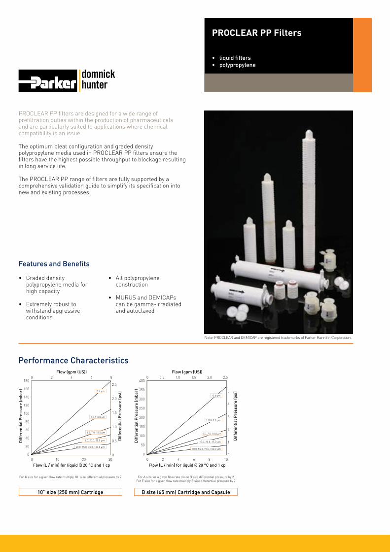
PROCLEAR PP filters are designed for a wide range of prefiltration duties within the production of pharmaceuticals and are particularly suited to applications where chemical compatibility is an issue.
The optimum pleat configuration and graded density polypropylene media used in PROCLEAR PP filters ensure the filters have the highest possible throughput to blockage resulting in long service life.
The PROCLEAR PP range of filters are fully supported by a comprehensive validation guide to simplify its specification into new and existing processes.
Features and Benefits
• Graded density polypropylene media for high capacity
• Extremely robust to withstand aggressive conditions
• All polypropylene construction
• MURUS and DEMICAPs can be gamma-irradiated and autoclaved
Performance Characteristics
PROCLEAR PP Filters
• liquid filters• polypropylene
Note: PROCLEAR and DEMICAP are registered trademarks of Parker Hannifin Corporation.
10¨ size (250 mm) Cartridge
180
160
140
120
100
80
60
40
20
0
Diff
eren
tial
Pre
ssur
e (m
bar)
2.5
2.0
1.5
1.0
0.5
0
Diff
eren
tial
Pre
ssur
e (p
si)
0 10 20 30
Flow (L / min) for liquid @ 20 °C and 1 cp
Flow (gpm (US))0 2 4 6 8
B size (65 mm) Cartridge and Capsule
Diff
eren
tial
Pre
ssur
e (m
bar)
Diff
eren
tial
Pre
ssur
e (p
si)
For K size for a given flow rate multiply 10¨ size differential pressure by 2 For A size for a given flow rate divide B size differential pressure by 2For E size for a given flow rate multiply B size differential pressure by 2
5.0, 7.0, 10.0 µm
400
350
300
250
200
150
100
50
0
5
4
3
2
1
00 2 4 6 8 10
Flow (L / min) for liquid @ 20 °C and 1 cp
Flow (gpm (US))0 0.5 1.0 1.5 2.0 2.5
15.0, 20.0, 25.0 µm
40.0, 55.0, 75.0, 100.0 µm
0.6 µm
1.0 & 3.0 µm
0.6 µm
1.0 & 3.0 µm
5.0, 7.0, 10.0 µm
15.0, 20.0, 25.0 µm
40.0, 55.0, 75.0, 100.0 µm

SpecificationsMaterials of Construction Filtration Membrane: Polypropylene Upstream Support: Polypropylene Downstream Support: Polypropylene
Filter Cartridges Inner Support Core: Polypropylene Outer Protection Cage: Polypropylene End Caps: Polypropylene End Caps Insert: 316L Stainless Steel *Not available in B & L endcap variants
MURUS Disposable Filter Capsules Core: Polypropylene Sleeve: Polypropylene End Caps Insert: 316L Stainless Steel Standard o-rings/gaskets: Silicone Capsule Body: Polypropylene Capsules Vent Seals: Silicone
DEMICAP Filter Capsules Core: Polypropylene Sleeve: Polypropylene Capsule Body: Polypropylene Capsules Vent Seals: Silicone Filling Bell: Polycarbonate
Syringe Filters Body: Polypropylene
Recommended Operating ConditionsFilter CartridgesUp to 70 °C (158 °F) continuous operating temperature and higher short-term temperatures during CIP to the following limits:
MURUS Disposable Filter CapsulesUp to 25 °C ( 77 °F) @ 5.5 barg (79.7 psig)Up to 60 °C (140 °F) @ 2.8 barg (40.6 psig)
Parker Hannifin certify that this product complies with the European Council Pressure Equipment Directive (PED) 97/23/EC Article 3, Paragraph 3 - Sound Engineering Practice (SEP). This product is intended for use with Group 1 & 2 Dangerous and Harmless Liquids and Group 2 Harmless Gases at the operating conditions stated in this document : In compliance with PED Article 3, Paragraph 3, SEP, this product does not bear the CE mark.
DEMICAP Filter CapsulesUp to 40 °C (104 °F) at line pressures up to 5.0 barg (72 psig).
Effective Filtration Area (EFA)10¨ (250 mm) up to 0.79 m2 (8.5 ft2)
SterilizationPROCLEAR PP filter cartridges can be sanitized with hot water at up to 90 °C (194 °F) and are compatible with a wide range of chemicals.
For detailed operational procedures and advice on cleaning and sterilization, please contact the Technical Support Group through your usual Parker domnick hunter contact. Biological SafetyMaterials conform to the relevant requirements of 21CFR Part 177 and current USP Plastics Class VI - 121 °C and ISO10993 equivalents.
Quality StandardsPharmaceutical grade products are manufactured in accordance with cGMP, 100% flushed with pharmaceutical grade purified water.
Gamma-IrradiationPROCLEAR PP MURUS & DEMICAP disposable filters can be gamma-irradiated up to a maximum dosage of 40 kGy.
Temperature Max. Forward dP °C °F (bar) (psi)
20 68 5.0 72.5
40 104 4.0 58.0
60 140 3.0 43.5
80 176 2.0 29.0
90 194 1.5 21.7
PROCLEAR PP Filters
Autoclave Steam-in-Place Cycles Temp Cycles Temp (30 min.)
Cartridges 10 130 °C (266 °F) 30 135 °C (275 °F)
MURUS 5 130 °C (266 °F) - -
DEMICAP 10 130 °C (266 °F) - -
Syringe 1 130 °C (266 °F) - -

Performance CharacteristicsTOC / ConductivityThe filtrate quality from a 10¨ (250 mm) PROCLEAR PP conforms to the requirements of current USP <643> (TOC) and USP <645> (conductivity) within the first 200 ml flush of purified water.
EndotoxinsAqueous extracts from the 10¨ (250 mm) PROCLEAR PP contain < 0.25 EU / ml when tested in accordance with the Limulus Amoebocyte Lysate test.
Non-Volatile Extractables (NVE)Total NVEs extracted in the first 5 litre flush of purified water for a 10¨ (250 mm)cartridge are <10 mg.
Total NVEs extracted in the first 5 litre flush of purified water for an A size 7.9¨ (200 mm) DEMICAP capsule are <5 mg.
Pharmaceutical ValidationA full validation guide is available upon request from Laboratory Services Group (LSG).
Oxidizable SubstancesPROCLEAR PP filter cartridges meet current USP and EP quality standards for sterile purified water for oxidizable substances following a <1 litre water flush.
PROCLEAR PP Filters

PROCLEAR PP Filters
Ordering Information
PCPP - -
Code ǀ Length (Nominal)
B* 2.5¨ (65 mm)A* 5¨ (125 mm)K 5¨ (125 mm)1 10¨ (250 mm)2 20¨ (500 mm)3 30¨ (750 mm)4 40¨ (1000 mm)
Code ǀ Micron
96 0.6 µm01 1.0 µm03 3.0 µm05 5.0 µm07 7.0 µm10 10.0 µm15 15.0 µm20 20.0 µm25 25.0 µm40 40.0 µm55 55.0 µm75 75.0 µm100* 100.0 µm
Code ǀ Variant
P Pharmaceutical
PLPP -
Code ǀ Length (Nominal)
K 5¨ (125 mm)1 10¨ (250 mm)2 20¨ (500 mm)3 30¨ (750 mm)
Code ǀ Micron
96 0.6 µm01 1.0 µm03 3.0 µm05 5.0 µm07 7.0 µm10 10.0 µm15 15.0 µm20 20.0 µm25 25.0 µm40 40.0 µm55 55.0 µm75 75.0 µm100 100.0 µm
Code ǀ Inlet Connection
A 3/4¨ Tri-ClampB 11/2¨ Tri-ClampD 1¨ HosebarbT 1¨ Tri-Clamp
Code ǀ Variant
P Pharmaceutical
MURUS Capsules
Code ǀ Outlet Connection
A 3/4¨ Tri-ClampB 11/2¨ Tri-ClampD 1¨ HosebarbT 1¨ Tri-Clamp
Code ǀ Grade
N Non-sterileS Pre-sterilized γ (>25 kGy)
Code ǀ Design
L In-LineT* T-Port
Cartridges
PEPP -
Code ǀ Length (Nominal)
E 4.4¨ (113 mm)B 5.5¨ (140 mm)A 7.9¨ (200 mm)
Code ǀ Micron
96 0.6 µm01 1.0 µm03 3.0 µm05 5.0 µm07 7.0 µm10 10.0 µm15 15.0 µm20 20.0 µm25 25.0 µm40 40.0 µm55 55.0 µm75 75.0 µm
Code ǀ Inlet Connection
T 1¨ Tri-ClampN 1/2¨ NPT MaleH 1/2¨ HosebarbG Stepped HosebarbM 1/4¨ NPT MaleQ Walther QCR Grommel / QCV 3/8¨ NPT Female
Code ǀ Variant
P Pharmaceutical
DEMICAP Capsules
Code ǀ Outlet Connection
T 1¨ Tri-ClampN 1/2¨ NPT MaleH 1/2¨ HosebarbG Stepped HosebarbM 1/4¨ NPT MaleQ Walther QCR Grommel / QCV 3/8¨ NPT Female
Code ǀ Grade
N Non-sterileS Pre-sterilized γ (>25 kGy)
Code ǀ Pack N°
3 Pack of 3
Code ǀ O-rings
E EPDMP PTFE Encapsulated SiliconeS* SiliconeV Viton
-
- -
PSPP -
Code ǀ Diameter
050 50 mm
Code ǀ Micron
96 0.6 µm01 1.0 µm03 3.0 µm05 5.0 µm07 7.0 µm10 10.0 µm15 15.0 µm20 20.0 µm25 25.0 µm40 40.0 µm55 55.0 µm75 75.0 µm
Code ǀ Variant
P Pharmaceutical
Syringe Filters
Code ǀ Grade
N Non-sterile
Code ǀ Options
S Standard
-
Code ǀ Pack N°
025 25 per box
Ratings based on efficiencies of > or = 99.98% using internal test procedure SOP018 based on ASTM F795-88 1993
Ratings based on efficiencies of > or = 99.98% using internal test procedure SOP018 based on ASTM F795-88 1993
Ratings based on efficiencies of > or = 99.98% using internal test procedure SOP018 based on ASTM F795-88 1993
DS_P_03_05/12 Rev. 4B
* Only available with a 1¨ Tri-Clamp
*Not available with A and B Size formats
Code ǀ Inlet Connection
F Female Luer LockG Stepped Hosebarb
Code ǀ Outlet Connection
F Female Luer LockG Stepped Hosebarb
Code ǀ Endcap (10¨)
B* dh DOEC BF / 226 BayonetD Fin / 222E Flat Top / 222G Recess / 222H UF RetrofitJ SOE (no o-ring)L* dh DOEN Internal 213R BF / 222 Bayonet
Code ǀ Endcap (Demi)
T TRUESEALY Demi StubZ Demi A & B Std
* Supplied in packs of 3.
* EPDM gaskets supplied as standard
* Silicone o-ring supplied as standard without having to specify the ‘S’ code.
Code ǀ Accessory
FB Filling Bell
G & H connections only
-
Parker domnick hunter has a continuous policy of product development and although the Company reserves the right to change specifications, it attempts to keep customers informed of any alterations. This publication is for general information only and customers are requested to contact our Process Filtration Sales Department for detailed information and advice on a products suitability for specific applications. All products are sold subject to the company’s Standard conditions of sale.
Code ǀ O-rings
E EPDMP PTFE Encapsulated SiliconeS SiliconeV Viton
Euro
pe:
+44
(0)1
91 4
1051
21
dhp
roce
ss@
park
er.c
om -
Nor
th A
mer
ica:
✆ to
ll fr
ee 8
77 7
84 2
234
✆ +
1 80
5 60
4 34
00
dhp
sale
s.na
@pa
rker
.com
w
ww.
park
er.c
om/d
hpha
rma

PROPOR BR filters have been specifically designed for the fast and cost-effective bioburden reduction of pharmaceutical solutions.
PROPOR BR filters feature an integral meltblown prefilter layer to maximize dirt holding capacity whilst the polyethersulphone membrane guarantees a bioburden log reduction of greater than 5 giving excellent microbial protection. This makes PROPOR BR filters ideal for bioburden reduction of LVPs prior to terminal sterilization.
PROPOR BR filters are also ideally suited to prefiltration and bioburden reduction prior to sterilizing grade membrane filters. The robust construction of PROPOR BR filters guarantees consistent performance on multiple batches.
Features and Benefits
Cartridge flow rates
• Brevundimonas diminuta retention of LRV >5 for efficient bioburden reduction
• Additional prefilter layer gives excellent throughput to blockage
• Low binding for minimal product loss
• MURUS and DEMICAPs can be gamma-irradiated and autoclaved
Performance Characteristics
PROPOR BR Filters
• liquid filters• polyethersulphone
Note: PROPOR and DEMICAP are registered trademarks of Parker Hannifin Corporation.
300
250
200
150
100
50
0
Diff
eren
tial
Pre
ssur
e (m
bar)
4
3
2
1
0
Diff
eren
tial
Pre
ssur
e (p
si)
0 5 10 15 20
Flow (L / min) for liquid @ 20 °C and 1 cp
Flow (gpm (US))0 1 2 3 4 5
MURUS flow rates (10¨ Size (250 mm))
300
250
200
150
100
50
0
Diff
eren
tial
Pre
ssur
e (m
bar)
4
3
2
1
0
Diff
eren
tial
Pre
ssur
e (p
si)
0 10 20 30
Flow (L / min) for liquid @ 20 °C and 1 cp
Flow (gpm (US))0 2 4 6 8
DEMICAP flow rates
600
500
400
300
200
100
0
Diff
eren
tial
Pre
ssur
e (m
bar)
8
7
6
5
4
3
2
1
0
Diff
eren
tial
Pre
ssur
e (p
si)
0 2 4 6 8 10
Flow (L / min) for liquid @ 20 °C and 1 cp
E Size
B Size
A Size
Flow (gpm (US))0 0.5 1.0 1.5 2.0 2.5
B Size
K Size
10¨ (250 mm)
A Size

SpecificationsMaterials of Construction Filtration Membrane: Polyethersulphone Prefilter Layer: Polyester Upstream Support: Polyester Downstream Support: Polyester
Filter Cartridges Inner Support Core: Polypropylene Outer Protection Cage: Polypropylene End Caps: Nylon End Caps Insert: 316L Stainless Steel
MURUS Disposable Filter Capsules Core: Polypropylene Sleeve: Polypropylene End Caps Insert: 316L Stainless Steel Standard o-rings/gaskets: Silicone Capsule Body: Polypropylene Capsules Vent Seals: Silicone
DEMICAP Filter Capsules Core: Polypropylene Sleeve: Polypropylene End Caps: Nylon Capsule Body: Nylon Capsules Vent Seals: Silicone Filling Bell: Polycarbonate
Syringe Filters Body: Polypropylene
Recommended Operating ConditionsFilter CartridgesUp to 70 °C (158 °F) continuous operating temperature and higher short-term temperatures during CIP to the following limits:
MURUS Disposable Filter CapsulesUp to 25 °C ( 77 °F) @ 5.5 barg (79.7 psig)Up to 60 °C (140 °F) @ 2.8 barg (40.6 psig)
Parker Hannifin certify that this product complies with the European Council Pressure Equipment Directive (PED) 97/23/EC Article 3, Paragraph 3 - Sound Engineering Practice (SEP). This product is intended for use with Group 1 & 2 Dangerous and Harmless Liquids and Group 2 Harmless Gases at the operating conditions stated in this document : In compliance with PED Article 3, Paragraph 3, SEP, this product does not bear the CE mark.
DEMICAP Filter CapsulesUp to 40 °C (104 °F) at line pressures up to 5.0 barg (72 psig).
Effective Filtration Area (EFA)10¨ (250 mm): 0.55 m2 (5.92 ft2)K Size: 0.26 m2 (2.79 ft2)A Size: 0.20 m2 (2.15 ft2)B Size: 0.10 m2 (1.07 ft2)E Size: 0.05 m2 (0.53 ft2)Syringe ø50 mm: 14.50 cm2 (2.25 in2)
Sterilization
PROPOR BR filter cartridges can be sanitized with hot water at up to 90 °C (194 °F) and are compatible with a wide range of chemicals.
For detailed operational procedures and advice on cleaning and sterilization, please contact the Technical Support Group through your usual Parker domnick hunter contact. Biological SafetyMaterials conform to the relevant requirements of 21CFR Part 177 and current USP Plastics Class VI - 121 °C and ISO10993 equivalents.
Quality StandardsPharmaceutical grade products are manufactured in accordance with cGMP, 100% flushed with pharmaceutical grade purified water and integrity tested prior to despatch. A sample of each lot is tested to demonstrate conformity to validated claims.
Gamma-IrradiationPROPOR BR MURUS & DEMICAP disposable filters can be gamma-irradiated up to a maximum dosage of 40 kGy.
Temperature Max. Forward dP °C °F (bar) (psi)
20 68 5.0 72.5
40 104 4.0 58.0
60 140 3.0 43.5
80 176 2.0 29.0
90 194 1.7 24.6
PROPOR BR Filters
Autoclave Steam-in-Place Cycles Temp Cycles Temp (30 min.)
Cartridges 10 130 °C (266 °F) 30 130 °C (266 °F)
MURUS 5 130 °C (266 °F) - -
DEMICAP 10 130 °C (266 °F) - -
Syringe 1 130 °C (266 °F) - -

Performance CharacteristicsTOC / ConductivityThe filtrate quality from a 10¨ (250 mm) PROPOR BR conforms to the requirements of current USP <643> (TOC) and USP <645> (conductivity) within the first 200 ml flush of purified water.
EndotoxinsAqueous extracts from the 10¨ (250 mm) PROPOR BR contain < 0.25 EU / ml when tested in accordance with the Limulus Amoebocyte Lysate test.
Non-Volatile Extractables (NVE)Total NVEs extracted in the first 5 litre flush of purified water for a 10¨ (250 mm)cartridge are <10 mg.
Total NVEs extracted in the first 5 litre flush of purified water for an A size 7.9¨ (200 mm) DEMICAP capsule are <5 mg.
Pharmaceutical ValidationA full validation guide is available upon request from Laboratory Services Group (LSG).
Oxidizable SubstancesPROPOR BR filter cartridges meet current USP and EP quality standards for sterile purified water for oxidizable substances following a <1 litre water flush.
Integrity Test DataAll filters are integrity testable to the following limits when wet with water and using air as the test gas.
Retention CharacteristicsPROPOR BR filter cartridges are validated to an LRV > 5 by bacterial challenge testing with Brevundimonas diminuta to current ASTM F838-05 methodology (107 organisms / cm2 EFAminimum) with typical in-house challenge levels being 1011 organisms per 10¨ (250 mm) module.
PROPOR BR Filters
Protein binding on membrane materials
140
120
100
80
60
40
20
0
Pro
tein
Ads
orpt
ion
(mg
/ cm
2 )
Nylon Polypropylene Polysulphone PVDF Pdh PES
Membrane Material
HSA
g-globulin
InsulinMicron Rating 0.2
Filter Cartridges / MURUS / DEMICAP
Min. Bubble Point (barg) 2.5
(psig) 36.0
Filter Cartridges / MURUS / DEMICAP / Syringe Filters
Diffusional Flow (barg) 1.7
Test Pressure (psig) 24.7
Filter Cartridges / MURUS / DEMICAP / Syringe Filters
Max. Diffusional Flow (10¨) 16.0
(ml / min) (K) 7.4
(A) 6.0
(B) 2.9
(E) 1.2
Flow rate comparison for bioburden reduction filters
180
160
140
120
100
80
60
40
20
0Diff
eren
tial
Pre
ssur
e @
10
L /
min
(mba
r)
Competitor A Competitor B PROPOR BR Nylon PVDF
Membrane Material

PROPOR BR Filters
Ordering Information
ZCBR - -
Code ǀ Length (Nominal)
B* 2.5¨ (65 mm)A* 5¨ (125 mm)K 5¨ (125 mm)1 10¨ (250 mm)2 20¨ (500 mm)3 30¨ (750 mm)4 40¨ (1000 mm)
Code ǀ Micron
020 0.20 µm
Code ǀ Variant
P Pharmaceutical
Code ǀ O-rings
E EPDMS SiliconeV Viton
ZLBR -
Code ǀ Length (Nominal)
K 5¨ (125 mm)1 10¨ (250 mm)2 20¨ (500 mm)3 30¨ (750 mm)
Code ǀ Micron
020 0.2 µm
Code ǀ Inlet Connection
A 3/4¨ Tri-ClampB 11/2¨ Tri-ClampD 1¨ HosebarbT 1¨ Tri-Clamp
Code ǀ Variant
P Pharmaceutical
MURUS Capsules
Code ǀ Outlet Connection
A 3/4¨ Tri-ClampB 11/2¨ Tri-ClampD 1¨ HosebarbT 1¨ Tri-Clamp
Code ǀ Grade
N Non-sterileS Pre-sterilized γ (>25 kGy)
Code ǀ Design
L In-LineT* T-Port
Cartridges
ZEBR -
Code ǀ Length (Nominal)
E 4.4¨ (113 mm)B 5.5¨ (140 mm)A 7.9¨ (200 mm)
Code ǀ Micron
020 0.2 µm
Code ǀ Inlet Connection
T 1¨ Tri-ClampN 1/2¨ NPT MaleH 1/2¨ HosebarbG Stepped HosebarbM 1/4¨ NPT MaleQ Walther QCR Grommel / QC
Code ǀ Variant
P Pharmaceutical
DEMICAP Capsules
Code ǀ Outlet Connection
T 1¨ Tri-ClampN 1/2¨ NPT MaleH 1/2¨ HosebarbG Stepped HosebarbM 1/4¨ NPT MaleQ Walther QCR Grommel / QC
Code ǀ Grade
N Non-sterileS Pre-sterilized γ (>25 kGy)
Code ǀ Pack N°
3 Pack of 3
Code ǀ O-rings
E EPDMS* SiliconeV Viton
-
- -
Code ǀ Accessory
FB Filling Bell
-
G & H connections only
ZSBR -
Code ǀ Diameter
050 50 mm
Code ǀ Micron
020 0.2 µm
Code ǀ Variant
P Pharmaceutical
Syringe Filters
Code ǀ Grade
N Non-sterile
Code ǀ Options
S Standard
-
Code ǀ Pack N°
025 25 per box
DS_P_04_02/14 Rev. 4C
* Only available with a 1¨ Tri-Clamp
Code ǀ Inlet Connection
F Female Luer LockG Stepped Hosebarb
Code ǀ Outlet Connection
F Female Luer LockG Stepped Hosebarb
Code ǀ Endcap (10¨)
C BF / 226 BayonetD Fin / 222E Flat Top / 222G Recess / 222R BF / 222 Bayonet
Code ǀ Endcap (Demi)
T TRUESEALY Demi StubZ Demi A & B Std
* Supplied in packs of 3.
* Silicone o-ring supplied as standard without having to specify the ‘S’ code.
Parker domnick hunter has a continuous policy of product development and although the Company reserves the right to change specifications, it attempts to keep customers informed of any alterations. This publication is for general information only and customers are requested to contact our Process Filtration Sales Department for detailed information and advice on a products suitability for specific applications. All products are sold subject to the company’s Standard conditions of sale.
Euro
pe:
+44
(0)1
91 4
1051
21
dhp
roce
ss@
park
er.c
om -
Nor
th A
mer
ica:
✆ to
ll fr
ee 8
77 7
84 2
234
✆ +
1 80
5 60
4 34
00
dhp
sale
s.na
@pa
rker
.com
w
ww.
park
er.c
om/d
hpha
rma

PROPOR HC sterilizing grade filters have been specifically designed for the effective and economical processing of difficult to filter solutions.
The optimized PROPOR HC PES membrane configuration features a highly asymmetric membrane prefilter layer, which significantly extends throughput and prevents the problems associated with premature filter blockage with complex solutions.
PROPOR HC filters are high capacity and fast flowing. The PES membrane is inherently low binding, which minimizes product loss due to protein or preservative adsorption. The filters have low extractable levels and broad chemical compatibility.
Features and Benefits
Cartridge flow rates
• Optimized membrane configuration allows up to ten times the throughput compared to single layer membrane products
• Integral prefilter layer can condense filter trains for greater processing economy
• Incorporates a fully validated and integrity testable 0.2 micron membrane for assurance of sterility
• Low binding for minimal product loss
Performance Characteristics
PROPOR HC Filters
• liquid filters• polyethersulphone
300
250
200
150
100
50
0
Diff
eren
tial
Pre
ssur
e (m
bar)
4
3
2
1
0
Diff
eren
tial
Pre
ssur
e (p
si)
0 2 4 6 8 10
Flow (L / min) for liquid @ 20 °C and 1 cp
Flow (gpm (US))0 0.5 1.0 1.5 2.0 2.5
MURUS flow rates (10¨ Size (250 mm))
300
250
200
150
100
50
0
Diff
eren
tial
Pre
ssur
e (m
bar)
4
3
2
1
0
Diff
eren
tial
Pre
ssur
e (p
si)
0 10 20 30
Flow (L / min) for liquid @ 20 °C and 1 cp
Flow (gpm (US))0 2 4 6 8
DEMICAP flow rates
600
500
400
300
200
100
0
Diff
eren
tial
Pre
ssur
e (m
bar)
8
7
6
5
4
3
2
1
0
Diff
eren
tial
Pre
ssur
e (p
si)
0 2 4 6 8 10
Flow (L / min) for liquid @ 20 °C and 1 cp
E Size
B Size
A Size
Flow (gpm (US))0 0.5 1.0 1.5 2.0 2.5
B Size
A Size
K Size
10¨ (250 mm)
Note: PROPOR and DEMICAP are registered trademarks of Parker Hannifin Corporation.

SpecificationsMaterials of Construction Filtration Membrane: Polyethersulphone Prefilter Membrane: Polyethersulphone Upstream Support: Polyester Downstream Support: Polyester
Filter Cartridges Inner Support Core: Polypropylene Outer Protection Cage: Polypropylene End Caps: Nylon End Caps Insert: 316L Stainless Steel
MURUS Disposable Filter Capsules Core: Polypropylene Sleeve: Polypropylene End Caps Insert: 316L Stainless Steel Standard o-rings/gaskets: Silicone Capsule Body: Polypropylene Capsules Vent Seals: Silicone
DEMICAP Filter Capsules Core: Polypropylene Sleeve: Polypropylene End Caps: Nylon Capsule Body: Nylon Capsules Vent Seals: Silicone Filling Bell: Polycarbonate
Syringe Filters Body: Polypropylene
Recommended Operating ConditionsFilter CartridgesUp to 70 °C (158 °F) continuous operating temperature and higher short-term temperatures during CIP to the following limits:
MURUS Disposable Filter CapsulesUp to 25 °C ( 77 °F) @ 5.5 barg (79.7 psig)Up to 60 °C (140 °F) @ 2.8 barg (40.6 psig)
Parker Hannifin certify that this product complies with the European Council Pressure Equipment Directive (PED) 97/23/EC Article 3, Paragraph 3 - Sound Engineering Practice (SEP). This product is intended for use with Group 1 & 2 Dangerous and Harmless Liquids and Group 2 Harmless Gases at the operating conditions stated in this document : In compliance with PED Article 3, Paragraph 3, SEP, this product does not bear the CE mark.
DEMICAP Filter CapsulesUp to 40 °C (104 °F) at line pressures up to 5.0 barg (72 psig).
Effective Filtration Area (EFA)10¨ (250 mm): 0.55 m2 (5.92 ft2)K Size: 0.26 m2 (2.79 ft2)A Size: 0.20 m2 (2.15 ft2)B Size: 0.10 m2 (1.07 ft2)E Size: 0.05 m2 (0.53 ft2)Syringe ø50 mm: 14.50 cm2 (2.25 in2)
Sterilization
PROPOR HC filter cartridges can be sanitized with hot water at up to 90 °C (194 °F) and are compatible with a wide range of chemicals.
For detailed operational procedures and advice on cleaning and sterilization, please contact the Technical Support Group through your usual Parker domnick hunter contact. Biological SafetyMaterials conform to the relevant requirements of 21CFR Part 177 and current USP Plastics Class VI - 121 °C and ISO10993 equivalents.
Quality StandardsPharmaceutical grade products are manufactured in accordance with cGMP, 100% flushed with pharmaceutical grade purified water and integrity tested prior to despatch. A sample of each lot is tested to demonstrate conformity to validated claims.
Gamma-IrradiationPROPOR HC MURUS & DEMICAP disposable filters can be gamma-irradiated up to a maximum dosage of 40 kGy.
Temperature Max. Forward dP °C °F (bar) (psi)
20 68 5.0 72.5
40 104 4.0 58.0
60 140 3.0 43.5
80 176 2.0 29.0
90 194 1.7 24.6
PROPOR HC Filters
Autoclave Steam-in-Place Cycles Temp Cycles Temp (30 min.)
Cartridges 10 130 °C (266 °F) 30 130 °C (266 °F)
MURUS 5 130 °C (266 °F) - -
DEMICAP 10 130 °C (266 °F) - -
Syringe 1 130 °C (266 °F) - -

Performance CharacteristicsTOC / ConductivityThe filtrate quality from a 10¨ (250 mm) PROPOR HC conforms to the requirements of current USP <643> (TOC) and USP <645> (conductivity) within the first 200 ml flush of purified water.
EndotoxinsAqueous extracts from the 10¨ (250 mm) PROPOR HC contain < 0.25 EU / ml when tested in accordance with the Limulus Amoebocyte Lysate test.
Non-Volatile Extractables (NVE)Total NVEs extracted in the first 5 litre flush of purified water for a 10¨ (250 mm)cartridge are <10 mg.
Total NVEs extracted in the first 5 litre flush of purified water for an A size 7.9¨ (200 mm) DEMICAP capsule are <5 mg.
Pharmaceutical ValidationA full validation guide is available upon request from Laboratory Services Group (LSG).
Oxidizable SubstancesPROPOR HC filter cartridges meet current USP and EP quality standards for sterile purified water for oxidizable substances following a <1 litre water flush.
Integrity Test DataAll filters are integrity testable to the following limits when wet with water and using air as the test gas.
Retention CharacteristicsPROPOR HC filter cartridges are validated by bacterial challenge testing with Brevundimonas diminuta to current ASTM F838-05 methodology (107 organisms / cm2 EFA minimum) with typical in-house challenge levels being 1011 organisms per 10¨ (250 mm) filter cartridge.
PROPOR HC Filters
Total volume throughput (g) vs time (s) for an insulin intermediate solution
160
140
120
100
80
60
40
20
0
Volu
me
Thro
ughp
ut (g
)
0 250 500 750 1000 1250
Time (s)
Dual layer PROPOR HC PES 0.2 µm
PVDF 0.2 µm
Protein binding on membrane materials
140
120
100
80
60
40
20
0
Pro
tein
Ads
orpt
ion
(mg
/ cm
2 )
Nylon Polypropylene Polysulphone PVDF Pdh PES
Membrane Material
HSA
g-globulin
InsulinMicron Rating 0.2
Filter Cartridges / MURUS / DEMICAP / Syringe Filters
Min. Bubble Point (barg) 3.4
(psig) 49.0
Filter Cartridges / MURUS / DEMICAP / Syringe Filters
Diffusional Flow (barg) 2.8
Test Pressure (psig) 40.6
Filter Cartridges / MURUS / DEMICAP / Syringe Filters
Max. Diffusional Flow (10¨) 18.0
(ml / min) (K) 8.4
(A) 6.7
(B) 3.2
(E) 1.4

PROPOR HC Filters
Ordering Information
ZCHC - -
Code ǀ Length (Nominal)
B* 2.5¨ (65 mm)A* 5¨ (125 mm)K 5¨ (125 mm)1 10¨ (250 mm)2 20¨ (500 mm)3 30¨ (750 mm)4 40¨ (1000 mm)
Code ǀ Micron
620 0.20 µm
Code ǀ Variant
P Pharmaceutical
Code ǀ O-rings
E EPDMS SiliconeV Viton
ZLHC -
Code ǀ Length (Nominal)
K 5¨ (125 mm)1 10¨ (250 mm)2 20¨ (500 mm)3 30¨ (750 mm)
Code ǀ Micron
620 0.2 µm
Code ǀ Inlet Connection
A 3/4¨ Tri-ClampB 11/2¨ Tri-ClampD 1¨ HosebarbT 1¨ Tri-Clamp
Code ǀ Variant
P Pharmaceutical
MURUS Capsules
Code ǀ Outlet Connection
A 3/4¨ Tri-ClampB 11/2¨ Tri-ClampD 1¨ HosebarbT 1¨ Tri-Clamp
Code ǀ Grade
N Non-sterileS Pre-sterilized γ (>25 kGy)
Code ǀ Design
L In-LineT* T-Port
Cartridges
ZEHC -
Code ǀ Length (Nominal)
E 4.4¨ (113 mm)B 5.5¨ (140 mm)A 7.9¨ (200 mm)
Code ǀ Micron
620 0.2 µm
Code ǀ Inlet Connection
T 1¨ Tri-ClampN 1/2¨ NPT MaleH 1/2¨ HosebarbG Stepped HosebarbM 1/4¨ NPT MaleQ Walther QCR Grommel / QC
Code ǀ Variant
P Pharmaceutical
DEMICAP Capsules
Code ǀ Outlet Connection
T 1¨ Tri-ClampN 1/2¨ NPT MaleH 1/2¨ HosebarbG Stepped HosebarbM 1/4¨ NPT MaleQ Walther QCR Grommel / QC
Code ǀ Grade
N Non-sterileS Pre-sterilized γ (>25 kGy)
Code ǀ Pack N°
3 Pack of 3
Code ǀ O-rings
E EPDMS* SiliconeV Viton
-
- -
Code ǀ Accessory
FB Filling Bell
-
G & H connections only
ZSHC -
Code ǀ Diameter
050 50 mm
Code ǀ Micron
620 0.2 µm
Code ǀ Variant
P Pharmaceutical
Syringe Filters
Code ǀ Grade
N Non-sterile
Code ǀ Options
S Standard
-
Code ǀ Pack N°
025 25 per box
DS_P_05_01/11 Rev. 4A
* Only available with a 1¨ Tri-Clamp
Code ǀ Inlet Connection
F Female Luer LockG Stepped Hosebarb
Code ǀ Outlet Connection
F Female Luer LockG Stepped Hosebarb
Code ǀ Endcap (10¨)
C BF / 226 BayonetD Fin / 222E Flat Top / 222G Recess / 222R BF / 222 Bayonet
Code ǀ Endcap (Demi)
T TRUESEALY Demi StubZ Demi A & B Std
* Supplied in packs of 3.
* Silicone o-ring supplied as standard without having to specify the ‘S’ code.
Parker domnick hunter has a continuous policy of product development and although the Company reserves the right to change specifications, it attempts to keep customers informed of any alterations. This publication is for general information only and customers are requested to contact our Process Filtration Sales Department for detailed information and advice on a products suitability for specific applications. All products are sold subject to the company’s Standard conditions of sale.
Euro
pe:
+44
(0)1
91 4
1051
21
dhp
roce
ss@
park
er.c
om -
Nor
th A
mer
ica:
✆ to
ll fr
ee 8
77 7
84 2
234
✆ +
1 80
5 60
4 34
00
dhp
sale
s.na
@pa
rker
.com
w
ww.
park
er.c
om/d
hpha
rma

PROPOR MR filters have been specifically designed for fast, effective and economical removal of mycoplasma from cell culture media in the biopharmaceutical industry.
Incorporating a highly retentive 0.1 micron rated PES membrane, PROPOR MR is validated against the industry standard Brevundimonas diminuta as well as Acholeplasma laidlawii, a common mycoplasma species found in contaminated cell cultures.
An asymmetric integral membrane prefilter layer provides PROPOR MR with the optimal membrane configuration for maximum capacity and flow rate. Quick processing times minimize the risk of contamination while still offering maximum protection from mycoplasma.
Features and Benefits
• Fully validated and integrity testable for assurance of sterility
• A typical LRV of >10 for Acholeplasma laidlawii for effective mycoplasma control
• Integral prefilter layer increases throughputs for reduction of filter trains
• Exceptional flow rates for quick processing of cell culture media
PROPOR MR Filters
• liquid filters• polyethersulphone
Note: PROPOR and DEMICAP are registered trademarks of Parker Hannifin Corporation.
Cartridge & MURUS flow rates
Performance Characteristics
500
400
300
200
100
0
Diff
eren
tial
Pre
ssur
e (m
bar)
7
6
5
4
3
2
1
0
Diff
eren
tial
Pre
ssur
e (p
si)
0 2 4 6 8 10
Flow (L / min) for liquid @ 20 °C and 1 cp
Flow (gpm (US))0 0.5 1.0 1.5 2.0 2.5
30¨ (750 mm)
20¨ (500 mm)
K Size
10¨ (250 mm)
DEMICAP flow rates
400
300
200
100
0
Diff
eren
tial
Pre
ssur
e (m
bar) 5
4
3
2
1
0
Diff
eren
tial
Pre
ssur
e (p
si)
0 1 2 3 4 5
Flow (L / min) for liquid @ 20 °C and 1 cp
Flow (gpm (US))0 0.2 0.4 0.6 0.8 1.0 1.2
E Size
B Size
A Size

PROPOR MR Filters
SpecificationsMaterials of Construction Core: Polypropylene Sleeve: Polypropylene End Caps: Nylon Filtration Membrane: Polyethersulphone Prefilter Membrane: Polyethersulphone
Filter Cartridges Upstream Support: Polypropylene / Polyester Downstream Support: Polyester Standard o-rings/gaskets: Silicone
MURUS Disposable Filter Capsules Upstream Support: Polypropylene / Polyester Downstream Support: Polyester Standard o-rings/gaskets: Silicone Capsule Body: Polypropylene Capsules Vent Seals: Silicone
DEMICAP Disposable Filter Capsules Upstream Support: Polyester Downstream Support: Polyester Membrane Separation Layer: Polyester Capsule Body: Nylon Capsules Vent Seals: Silicone Filling Bell: Polycarbonate
Recommended Operating ConditionsFilter CartridgesUp to 70 °C (158 °F) continuous operating temperature and higher short-term temperatures during CIP to the following limits:
MURUS Disposable Filter CapsulesUp to 25 °C ( 77 °F) @ 5.5 barg (79.7 psig)Up to 60 °C (140 °F) @ 2.8 barg (40.6 psig)
Parker Hannifin certify that this product complies with the European Council Pressure Equipment Directive (PED) 97/23/EC Article 3, Paragraph 3 - Sound Engineering Practice (SEP). This product is intended for use with Group 1 & 2 Dangerous and Harmless Liquids and Group 2 Harmless Gases at the operating conditions stated in this document : In compliance with PED Article 3, Paragraph 3, SEP, this product does not bear the CE mark.
DEMICAP Disposable Filter CapsulesUp to 40 °C 104 °F) at line pressures up to 5.0 barg (72 psig).
Effective Filtration Area (EFA)10¨ (250 mm): 0.50 m2 (5.38 ft2)K Size: 0.24 m2 (2.58 ft2)A Size: 0.19 m2 (2.09 ft2)B Size: 0.10 m2 (1.03 ft2)E Size: 0.05 m2 (0.49 ft2)
SterilizationPROPOR MR filter cartridges can be sanitized with hot water at up to 90 °C (194 °F) and are compatible with a wide range of chemicals.
For detailed operational procedures and advice on cleaning and sterilisation, please contact the Technical Support Group through your usual Parker domnick hunter contact. Food and Biological SafetyMaterials conform to the relevant requirements of 21CFR Part 177 and current USP Plastics Class VI - 121 °C and ISO10993 equivalents.
Quality StandardsPharmaceutical grade products are manufactured in accordance with cGMP, 100% flushed with pharmaceutical purified water and integrity tested prior to despatch. A sample of each lot is tested to demonstrate conformity to validated claims.
Gamma-IrradiationPROPOR MR MURUS disposable filters can be gamma-irradiated up to a maximum dosage of 40 kGy.
Temperature Max. Forward dP °C °F (bar) (psi)
20 68 5.0 72.5
40 104 4.0 58.0
60 140 3.0 43.5
80 176 2.0 29.0
90 194 1.7 24.6
Autoclave Steam-in-Place Cycles Temp Cycles Temp (30 min.)
Cartridges 10 130 °C (266 °F) 5 130 °C (266 °F)
MURUS 10 130 °C (266 °F) - -
DEMICAP 3 130 °C (266 °F) - -
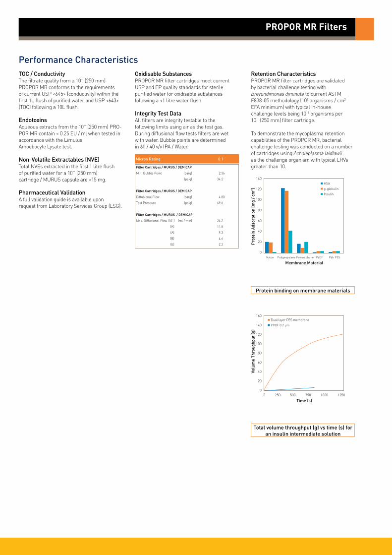
Performance CharacteristicsTOC / ConductivityThe filtrate quality from a 10¨ (250 mm) PROPOR MR conforms to the requirements of current USP <645> (conductivity) within the first 1L flush of purified water and USP <643> (TOC) following a 10L flush.
EndotoxinsAqueous extracts from the 10¨ (250 mm) PRO-POR MR contain < 0.25 EU / ml when tested in accordance with the Limulus Amoebocyte Lysate test.
Non-Volatile Extractables (NVE)Total NVEs extracted in the first 1 litre flush of purified water for a 10¨ (250 mm) cartridge / MURUS capsule are <15 mg.
Pharmaceutical ValidationA full validation guide is available upon request from Laboratory Services Group (LSG).
Oxidisable SubstancesPROPOR MR filter cartridges meet current USP and EP quality standards for sterile purified water for oxidisable substances following a <1 litre water flush.
Integrity Test DataAll filters are integrity testable to the following limits using air as the test gas. During diffusional flow tests filters are wet with water. Bubble points are determined in 60 / 40 v/v IPA / Water.
Retention CharacteristicsPROPOR MR filter cartridges are validated by bacterial challenge testing with Brevundimonas diminuta to current ASTM F838-05 methodology (107 organisms / cm2 EFA minimum) with typical in-house challenge levels being 1011 organisms per 10¨ (250 mm) filter cartridge.
To demonstrate the mycoplasma retention capabilities of the PROPOR MR, bacterial challenge testing was conducted on a number of cartridges using Acholeplasma laidlawii as the challenge organism with typical LRVs greater than 10.
PROPOR MR Filters
Total volume throughput (g) vs time (s) for an insulin intermediate solution
160
140
120
100
80
60
40
20
0
Volu
me
Thro
ughp
ut (g
)
0 250 500 750 1000 1250
Time (s)
Dual layer PES membrane
PVDF 0.2 µm
Protein binding on membrane materials
140
120
100
80
60
40
20
0P
rote
in A
dsor
ptio
n (m
g /
cm2 )
Nylon Polypropylene Polysulphone PVDF Pdh PES
Membrane Material
HSA
g-globulin
Insulin
Micron Rating 0.1
Filter Cartridges / MURUS / DEMICAP
Min. Bubble Point (barg) 2.36
(psig) 34.2
Filter Cartridges / MURUS / DEMICAP
Diffusional Flow (barg) 4.80
Test Pressure (psig) 69.6
Filter Cartridges / MURUS / DEMICAP
Max. Diffusional Flow (10¨) (ml / min) 24.2
(K) 11.5
(A) 9.3
(B) 4.6
(E) 2.2

PROPOR MR Filters
Ordering Information
ZCMR - -
Code ǀ Length (Nominal)
K 5¨ (125 mm)1 10¨ (250 mm)2 20¨ (500 mm)3 30¨ (750 mm)4 40¨ (1000 mm)
Code ǀ Micron
610 0.1 µm
Code ǀ Endcap (10¨)
B dh DOEC BF / 226 BayonetG Recess / 222R BF / 222 Bayonet
Code ǀ Variant
P Pharmaceutical
Code ǀ O-rings1
E EPDM2
S SiliconeV Viton
ZLMR -
Code ǀ Length (Nominal)
K 5¨ (125 mm)1 10¨ (250 mm)2 20¨ (500 mm)3 30¨ (750 mm)
Code ǀ Micron
610 0.1 µm
Code ǀ Inlet Connection
A 3/4¨ Tri-ClampB 11/2¨ Tri-ClampD 1¨ HosebarbT 1¨ Tri-Clamp
Code ǀ Variant
P Pharmaceutical
MURUS Capsules
Code ǀ Outlet Connection
A 3/4¨ Tri-ClampB 11/2¨ Tri-ClampD 1¨ HosebarbT 1¨ Tri-Clamp
Code ǀ Grade
N Non-sterileS Pre-sterilized γ (>25 kGy)
Code ǀ Design
L In-LineT* T-Port
Cartridges
1 Silicone o-ring supplied as standard without having to specify the ‘S’ code2 EPDM - Ethylene Propylene Diene Monomer Rubber
Code ǀ O-rings1
E EPDM2
S SiliconeV Viton
1 Silicone o-ring supplied as standard without having to specify the ‘S’ code2 EPDM - Ethylene Propylene Diene Monomer Rubber
- -
DS_P_10_10/12 Rev. 1B
* Only available with a 1¨ Tri-Clamp
Parker domnick hunter has a continuous policy of product development and although the Company reserves the right to change specifications, it attempts to keep customers informed of any alterations. This publication is for general information only and customers are requested to contact our Process Filtration Sales Department for detailed information and advice on a products suitability for specific applications. All products are sold subject to the company’s Standard conditions of sale.
ZEMR -
Code ǀ Length (Nominal)
E 4.4¨ (113 mm)B 5.5¨ (140 mm)A 7.9¨ (200 mm)
Code ǀ Micron
610 0.1 µm
Code ǀ Inlet Connection
T 1¨ Tri-ClampN 1/2¨ NPT MaleH 1/2¨ HosebarbG Stepped Hosebarb
Code ǀ Variant
P Pharmaceutical
DEMICAP Capsules
Code ǀ Outlet Connection
T 1¨ Tri-ClampN 1/2¨ NPT MaleH 1/2¨ HosebarbG Stepped Hosebarb
Code ǀ Grade
N Non-sterileS Pre-sterilized γ (>25 kGy)
Code ǀ Pack N°
3 Pack of 3
-
Code ǀ Accessory
FB Filling Bell
-
G & H connections only
Syringe Filters
ZSMR -
Code ǀ Diameter
050 50 mm
Code ǀ Micron
610 0.1 µm
Code ǀ Variant
P Pharmaceutical
Code ǀ Grade
N Non-sterile
Code ǀ Options
S Standard
-
Code ǀ Pack N°
025 25 per box
Code ǀ Inlet Connection
F Female Luer LockG Stepped Hosebarb
Code ǀ Outlet Connection
F Female Luer LockG Stepped Hosebarb
Euro
pe:
+44
(0)1
91 4
1051
21
dhp
roce
ss@
park
er.c
om -
Nor
th A
mer
ica:
✆ to
ll fr
ee 8
77 7
84 2
234
✆ +
1 80
5 60
4 34
00
dhp
sale
s.na
@pa
rker
.com
w
ww.
park
er.c
om/d
hpha
rma

PROPOR SG sterilizing grade filters feature a microbially retentive polyethersulphone membrane for fast, reliable and cost-effective sterile filtration of pharmaceutical fluids.
The asymmetric pore structure and high voids volume of the PROPOR SG membrane allow high throughputs and exceptionally high flow rates compared with competitive PES and alternative membranes. Low protein and preservativebinding properties minimize product loss due to adsorption.
PROPOR SG filters are optimized for pharmaceutical processing. They have low extractable levels and broad chemical compatibility across the full pH range including organic solvents.
Features and Benefits
Cartridge flow rates0.2 µm Cartridge
• Up to 3.5 times higher flow rates than competitive sterilizing grade filters
• Fully validated and integrity testable membrane for assurance of sterility
• Low binding for minimal product loss
• MURUS and DEMICAPs can be gamma-irradiated and autoclaved
Performance Characteristics
PROPOR SG Filters
• liquid filters• polyethersulphone
Note: PROPOR and DEMICAP are registered trademarks of Parker Hannifin Corporation.
300
250
200
150
100
50
0
Diff
eren
tial
Pre
ssur
e (m
bar)
4
3
2
1
0
Diff
eren
tial
Pre
ssur
e (p
si)
0 2 4 6 8 10
Flow (L / min) for liquid @ 20 °C and 1 cp
Flow (gpm (US))0 0.5 1.0 1.5 2.0 2.5
MURUS flow rates (10¨ Size (250 mm)) 0.2 µm Capsule
250
200
150
100
50
0
Diff
eren
tial
Pre
ssur
e (m
bar)
2.5
2.0
1.5
1.0
0.5
0
Diff
eren
tial
Pre
ssur
e (p
si)
0 10 20 30
Flow (L / min) for liquid @ 20 °C and 1 cp
Flow (gpm (US))0 2 4 6 8
DEMICAP flow rates0.2 µm Capsule
600
500
400
300
200
100
0
Diff
eren
tial
Pre
ssur
e (m
bar)
8
7
6
5
4
3
2
1
0
Diff
eren
tial
Pre
ssur
e (p
si)
0 2 4 6 8 10
Flow (L / min) for liquid @ 20 °C and 1 cp
E Size
B Size
A Size
Flow (gpm (US))0 0.5 1.0 1.5 2.0 2.5
B Size
A Size
K Size
10¨ (250 mm)

SpecificationsMaterials of Construction Filtration Membrane: Polyethersulphone Upstream Support: Polyester Downstream Support: Polyester
Filter Cartridges Inner Support Core: Polypropylene Outer Protection Cage: Polypropylene End Caps: Nylon End Caps Insert: 316L Stainless Steel
MURUS Disposable Filter Capsules Core: Polypropylene Sleeve: Polypropylene End Caps Insert: 316L Stainless Steel Standard o-rings/gaskets: Silicone Capsule Body: Polypropylene Capsules Vent Seals: Silicone
DEMICAP Filter Capsules Core: Polypropylene Sleeve: Polypropylene End Caps: Nylon Capsule Body: Nylon Capsules Vent Seals: Silicone Filling Bell: Polycarbonate
Syringe Filters Body: Polypropylene
Recommended Operating ConditionsFilter CartridgesUp to 70 °C (158 °F) continuous operating temperature and higher short-term temperatures during CIP to the following limits:
MURUS Disposable Filter CapsulesUp to 25 °C ( 77 °F) @ 5.5 barg (79.7 psig)Up to 60 °C (140 °F) @ 2.8 barg (40.6 psig)
Parker Hannifin certify that this product complies with the European Council Pressure Equipment Directive (PED) 97/23/EC Article 3, Paragraph 3 - Sound Engineering Practice (SEP). This product is intended for use with Group 1 & 2 Dangerous and Harmless Liquids and Group 2 Harmless Gases at the operating conditions stated in this document : In compliance with PED Article 3, Paragraph 3, SEP, this product does not bear the CE mark.
DEMICAP Filter CapsulesUp to 40 °C (104 °F) at line pressures up to 5.0 barg (72 psig).
Effective Filtration Area (EFA)10¨ (250 mm): 0.55 m2 (5.92 ft2)K Size: 0.26 m2 (2.79 ft2)A Size: 0.20 m2 (2.15 ft2)B Size: 0.10 m2 (1.07 ft2)E Size: 0.05 m2 (0.53 ft2)Syringe ø50 mm: 14.50 cm2 (2.25 in2)
Sterilization
PROPOR SG filter cartridges can be sanitized with hot water at up to 90 °C (194 °F) and are compatible with a wide range of chemicals.
For detailed operational procedures and advice on cleaning and sterilization, please contact the Technical Support Group through your usual Parker domnick hunter contact. Biological SafetyMaterials conform to the relevant requirements of 21CFR Part 177 and current USP Plastics Class VI - 121 °C and ISO10993 equivalents.
Quality StandardsPharmaceutical grade products are manufactured in accordance with cGMP, 100% flushed with pharmaceutical grade purified water and integrity tested prior to despatch. A sample of each lot is tested to demonstrate conformity to validated claims.
Gamma-IrradiationPROPOR SG MURUS & DEMICAP disposable filters can be gamma-irradiated up to a maximum dosage of 40 kGy.
Temperature Max. Forward dP °C °F (bar) (psi)
20 68 5.0 72.5
40 104 4.0 58.0
60 140 3.0 43.5
80 176 2.0 29.0
90 194 1.7 24.6
PROPOR SG Filters
Autoclave Steam-in-Place Cycles Temp Cycles Temp (30 min.)
Cartridges 10 130 °C (266 °F) 30 130 °C (266 °F)
MURUS 5 130 °C (266 °F) - -
DEMICAP 10 130 °C (266 °F) - -
Syringe 1 130 °C (266 °F) - -

Performance CharacteristicsTOC / ConductivityThe filtrate quality from a 10¨ (250 mm) PROPOR SG conforms to the requirements of current USP <643> (TOC) and USP <645> (conductivity) within the first 200 ml flush of purified water.
EndotoxinsAqueous extracts from the 10¨ (250 mm) PROPOR SG contain < 0.25 EU / ml when tested in accordance with the Limulus Amoebocyte Lysate test.
Non-Volatile Extractables (NVE)Total NVEs extracted in the first 5 litre flush of purified water for a 10¨ (250 mm)cartridge are <10 mg.
Total NVEs extracted in the first 5 litre flush of purified water for an A size 7.9¨ (200 mm) DEMICAP capsule are <5 mg.
Pharmaceutical ValidationA full validation guide is available upon request from Laboratory Services Group (LSG).
Oxidizable SubstancesPROPOR SG filter cartridges meet current USP and EP quality standards for sterile purified water for oxidizable substances following a <1 litre water flush.
Integrity Test DataAll filters are integrity testable to the following limits when wet with water and using air as the test gas.
*Bubble point for 0.1 µm product is in 60/40 v/v IPA/Water .
Retention CharacteristicsPROPOR SG filter cartridges are validated by bacterial challenge testing with Brevundimonas diminuta to current ASTM F838-05 methodology (107 organisms / cm2 EFA minimum) with typical in-house challenge levels being 1011 organisms per 10¨ (250 mm) filter cartridge.
PROPOR SG Filters
Protein binding on membrane materials
140
120
100
80
60
40
20
0
Pro
tein
Ads
orpt
ion
(mg
/ cm
2 )
Nylon Polypropylene Polysulphone PVDF Pdh PES
Membrane Material
HSA
g-globulin
InsulinMicron Rating 0.1 0.2 0.45
Filter Cartridges / MURUS / DEMICAP / Syringe FIlters
Min. Bubble Point* (barg) 2.36 3.38 2.48
(psig) 34.2 49.0 36.0
Filter Cartridges / MURUS / DEMICAP / Syringe Filters
Diffusional Flow (barg) 4.8 2.8 1.7
Test Pressure (psig) 69.6 40.6 24.9
Filter Cartridges / MURUS / DEMICAP / Syringe Filters
Max. Diffusional Flow (10¨) 27.0 16.0 16.0
(ml / min) (K) 12.6 7.5 7.5
(A) 10.1 5.8 5.8
(B) 4.9 2.9 2.9
(E) 2.1 1.4 1.4
Differential pressure comparison of 10¨ (250 mm) sterilising grade filters
350
300
250
200
150
100
50
0Diff
eren
tial
Pre
ssur
e @
10
L /
min
(mba
r)
Competitor A Competitor B Competitor A PROPOR SG Nylon PVDF PES
Membrane Material

PROPOR SG Filters
Ordering Information
ZCSG - -
Code ǀ Length (Nominal)
B* 2.5¨ (65 mm)A* 5¨ (125 mm)K 5¨ (125 mm)1 10¨ (250 mm)2 20¨ (500 mm)3 30¨ (750 mm)4 40¨ (1000 mm)
Code ǀ Micron
010 0.10 µm020 0.20 µm045 0.45 µm
Code ǀ Variant
P Pharmaceutical
Code ǀ O-rings
E EPDMS SiliconeV Viton
ZLSG -
Code ǀ Length (Nominal)
K 5¨ (125 mm)1 10¨ (250 mm)2 20¨ (500 mm)3 30¨ (750 mm)
Code ǀ Micron
010 0.10 µm020 0.20 µm045 0.45 µm
Code ǀ Inlet Connection
A 3/4¨ Tri-ClampB 11/2¨ Tri-ClampD 1¨ HosebarbT 1¨ Tri-Clamp
Code ǀ Variant
P Pharmaceutical
MURUS Capsules
Code ǀ Outlet Connection
A 3/4¨ Tri-ClampB 11/2¨ Tri-ClampD 1¨ HosebarbT 1¨ Tri-Clamp
Code ǀ Grade
N Non-sterileS Pre-sterilized γ (>25 kGy)
Code ǀ Design
L In-LineT* T-Port
Cartridges
ZESG -
Code ǀ Length (Nominal)
E 4.4¨ (113 mm)B 5.5¨ (140 mm)A 7.9¨ (200 mm)
Code ǀ Micron
010 0.10 µm020 0.20 µm045 0.45 µm
Code ǀ Inlet Connection
T 1¨ Tri-ClampN 1/2¨ NPT MaleH 1/2¨ HosebarbG Stepped HosebarbM 1/4¨ NPT MaleQ Walther QCR Grommel / QC
Code ǀ Variant
P Pharmaceutical
DEMICAP Capsules
Code ǀ Outlet Connection
T 1¨ Tri-ClampN 1/2¨ NPT MaleH 1/2¨ HosebarbG Stepped HosebarbM 1/4¨ NPT MaleQ Walther QCR Grommel / QC
Code ǀ Grade
N Non-sterileS Pre-sterilized γ (>25 kGy)
Code ǀ Pack N°
3 Pack of 3
Code ǀ O-rings
E EPDMS* SiliconeV Viton
-
- -
Code ǀ Accessory
FB Filling Bell
-
G & H connections only
ZSSG -
Code ǀ Diameter
050 50 mm
Code ǀ Micron
010 0.10 µm020 0.20 µm045 0.45 µm
Code ǀ Variant
P Pharmaceutical
Syringe Filters
Code ǀ Grade
N Non-sterile
Code ǀ Options
S Standard
-
Code ǀ Pack N°
025 25 per box
DS_P_07_07/13 Rev. 4C
* Only available with a 1¨ Tri-Clamp
Code ǀ Inlet Connection
F Female Luer LockG Stepped Hosebarb
Code ǀ Outlet Connection
F Female Luer LockG Stepped Hosebarb
Code ǀ Endcap (10¨)
C BF / 226 BayonetD Fin / 222E Flat Top / 222G Recess / 222R BF / 222 Bayonet
Code ǀ Endcap (Demi)
SK RetrofitT TRUESEALY Demi StubZ Demi A & B Std
* Supplied in packs of 3.
* Silicone o-ring supplied as standard without having to specify the ‘S’ code.
Parker domnick hunter has a continuous policy of product development and although the Company reserves the right to change specifications, it attempts to keep customers informed of any alterations. This publication is for general information only and customers are requested to contact our Process Filtration Sales Department for detailed information and advice on a products suitability for specific applications. All products are sold subject to the company’s Standard conditions of sale.
Euro
pe:
+44
(0)1
91 4
1051
21
dhp
roce
ss@
park
er.c
om -
Nor
th A
mer
ica:
✆ to
ll fr
ee 8
77 7
84 2
234
✆ +
1 80
5 60
4 34
00
dhp
sale
s.na
@pa
rker
.com
w
ww.
park
er.c
om/d
hpha
rma
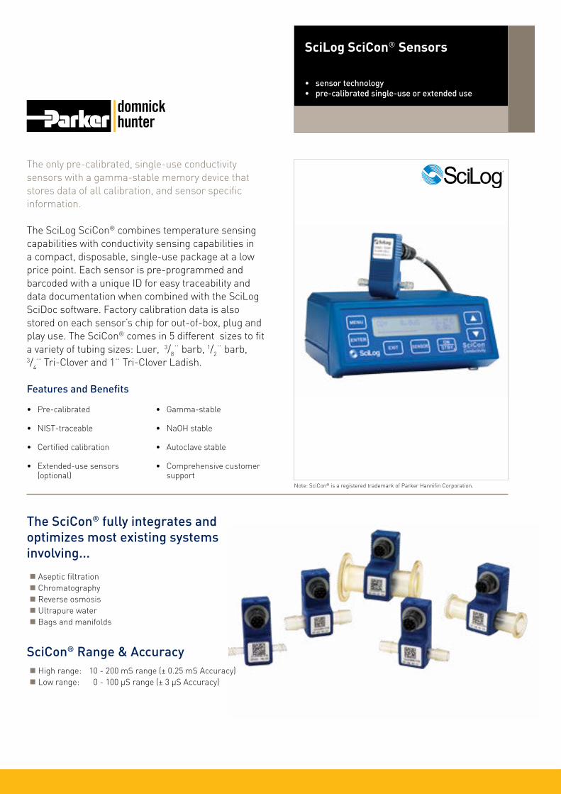
The only pre-calibrated, single-use conductivity sensors with a gamma-stable memory device that stores data of all calibration, and sensor specific information.
The SciLog SciCon® combines temperature sensing capabilities with conductivity sensing capabilities in a compact, disposable, single-use package at a low price point. Each sensor is pre-programmed and barcoded with a unique ID for easy traceability and data documentation when combined with the SciLog SciDoc software. Factory calibration data is also stored on each sensor’s chip for out-of-box, plug and play use. The SciCon® comes in 5 different sizes to fit a variety of tubing sizes: Luer, 3/8¨ barb, 1/2¨ barb, 3/4¨ Tri-Clover and 1¨ Tri-Clover Ladish.
Features and Benefits
• Pre-calibrated
• NIST-traceable
• Certified calibration
• Extended-use sensors (optional)
• Gamma-stable
• NaOH stable
• Autoclave stable
• Comprehensive customer support
SciLog SciCon® Sensors
• sensor technology• pre-calibrated single-use or extended use
Note: SciCon® is a registered trademark of Parker Hannifin Corporation.
SciCon® Range & Accuracy High range: 10 - 200 mS range (± 0.25 mS Accuracy) Low range: 0 - 100 µS range (± 3 µS Accuracy)
The SciCon® fully integrates and optimizes most existing systems involving...
Aseptic filtration Chromatography Reverse osmosis Ultrapure water Bags and manifolds
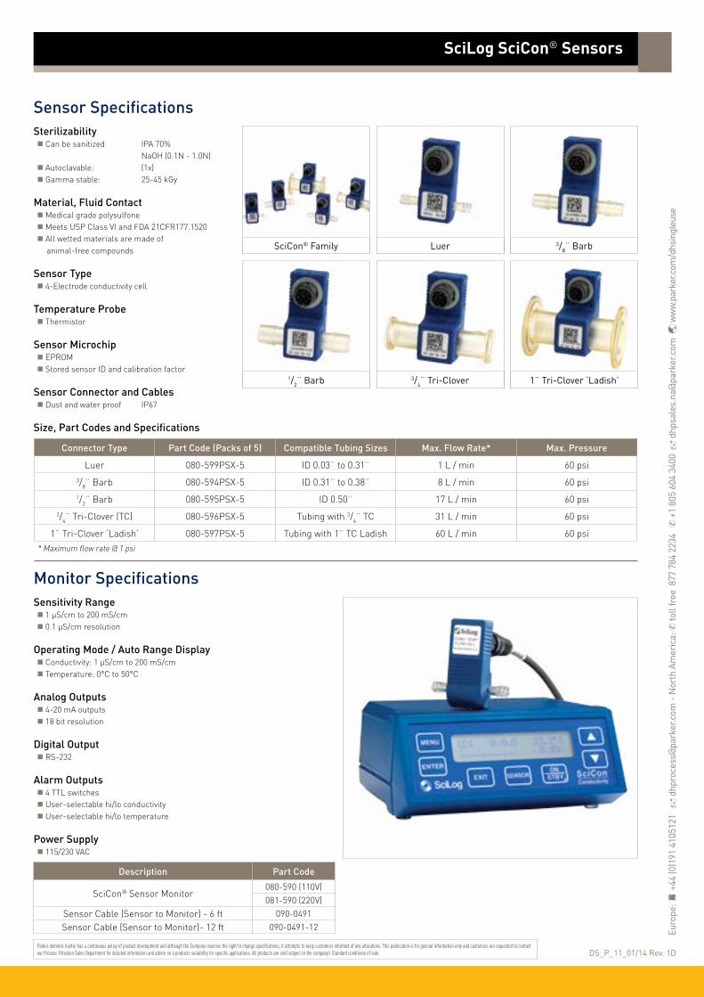
SciLog SciCon® Sensors
Sensor SpecificationsSterilizability Can be sanitized IPA 70% NaOH (0.1N - 1.0N) Autoclavable: (1x) Gamma stable: 25-45 kGy
Material, Fluid Contact Medical grade polysulfone Meets USP Class VI and FDA 21CFR177.1520 All wetted materials are made of animal-free compounds
Sensor Type 4-Electrode conductivity cell
Temperature Probe Thermistor
Sensor Microchip EPROM Stored sensor ID and calibration factor
Sensor Connector and Cables Dust and water proof IP67
Size, Part Codes and Specifications
Monitor SpecificationsSensitivity Range 1 µS/cm to 200 mS/cm 0.1 µS/cm resolution
Operating Mode / Auto Range Display Conductivity: 1 µS/cm to 200 mS/cm Temperature: 0°C to 50°C
Analog Outputs 4-20 mA outputs 18 bit resolution
Digital Output RS-232
Alarm Outputs 4 TTL switches User-selectable hi/lo conductivity User-selectable hi/lo temperature
Power Supply 115/230 VAC
Luer 3/8¨ Barb
1/2¨ Barb 3/4¨ Tri-Clover 1¨ Tri-Clover ‘Ladish’
SciCon® Family
Connector Type Part Code (Packs of 5) Compatible Tubing Sizes Max. Flow Rate* Max. Pressure
Luer 080-599PSX-5 ID 0.03¨ to 0.31¨ 1 L / min 60 psi3/8¨ Barb 080-594PSX-5 ID 0.31¨ to 0.38¨ 8 L / min 60 psi1/2¨ Barb 080-595PSX-5 ID 0.50¨ 17 L / min 60 psi
3/4¨ Tri-Clover (TC) 080-596PSX-5 Tubing with 3/4¨ TC 31 L / min 60 psi
1¨ Tri-Clover ‘Ladish’ 080-597PSX-5 Tubing with 1¨ TC Ladish 60 L / min 60 psi
* Maximum flow rate @ 1 psi
DS_P_11_01/14 Rev. 1DParker domnick hunter has a continuous policy of product development and although the Company reserves the right to change specifications, it attempts to keep customers informed of any alterations. This publication is for general information only and customers are requested to contact our Process Filtration Sales Department for detailed information and advice on a products suitability for specific applications. All products are sold subject to the company’s Standard conditions of sale.
Description Part Code
SciCon® Sensor Monitor 080-590 (110V)081-590 (220V)
Sensor Cable (Sensor to Monitor) - 6 ft 090-0491
Sensor Cable (Sensor to Monitor)- 12 ft 090-0491-12 Euro
pe:
+44
(0)1
91 4
1051
21
dhp
roce
ss@
park
er.c
om -
Nor
th A
mer
ica:
✆ to
ll fr
ee 8
77 7
84 2
234
✆ +
1 80
5 60
4 34
00
dhp
sale
s.na
@pa
rker
.com
w
ww.
park
er.c
om/d
hsin
gleu
se

The only pre-calibrated, single-use pressure sensors with with a gamma-stable memory device that stores data of all calibration, and sensor specific information.
The SciLog SciPres® combines pressure sensing capabilities and the convenience of disposability with easy setup. Each sensor is preprogrammed and barcoded with a unique ID for easy traceability and data documentation when combined with the SciLog SciDoc software. Factory calibration data is also stored on each sensor’s chip for out-of-box, plug and play use. The SciPres® comes in 5 different sizes to fit a variety of tubing sizes: Luer, 3/8¨ barb, 1/2¨ barb, 3/4¨ Tri-Clover and 1¨ Tri-Clover Ladish.
Features and Benefits
• Pre-calibrated
• NIST-traceable
• Certified calibration
• Extended-use sensors (optional)
• Gamma-stable
• NaOH stable
• Autoclave stable
• Comprehensive customer support
SciLog SciPres® Sensors
• sensor technology• pre-calibrated single-use or extended use
Note: SciPres® is a registered trademark of Parker Hannifin Corporation.
SciPres® Range & Accuracy Pressure range: -5 to 60 psi Pressure accuracy: ± 0.30 psi
The SciPres® fully integrates and optimizes most existing systems involving...
Filtration Chromatography Reverse osmosis Fermentation Bags and manifolds

SciLog SciPres® Sensors
Sensor SpecificationsSterilizability Can be sanitized IPA 70% NaOH (0.1N - 1.0N) Autoclavable: (1x) Gamma stable: 25-45 kGy
Material, Fluid Contact Medical grade polysulfone Meets USP Class VI and FDA 21CFR177.1520 All wetted materials are made of animal-free compounds
Sensor Type Medical grade Resistive Sensing element with on-chip temperature compensation
Sensor Microchip EPROM Stored sensor ID and calibration factor
Sensor Connector and Cables Dust and water proof IP67
Size, Part Codes and Specifications
Monitor SpecificationsSensor Inputs Up to three simultaneously
Sensor Readout P1, P2 and P3 Differential pressure (dP) Transmembrane pressure (TMP) Display of dP and TMP are user-selectable
Analog Outputs 4-20 mA outputs for P1, P2, P3 and dP or TMP 18 bit resolution
Digital Output RS-232
Alarm Outputs 4 TTL switches User-selectable hi/lo pressure limit settings for P1, P2, P2 and dP or TMP
Power Supply 115/230 VAC
Luer 3/8¨ Barb
1/2¨ Barb 3/4¨ Tri-Clover 1¨ Tri-Clover ‘Ladish’
SciPres® Family
Connector Type Part Code (Packs of 5) Compatible Tubing Sizes Max. Flow Rate* Max. Pressure
Luer 080-699PSX-5 ID 0.03¨ to 0.31¨ 1 L / min 60 psi3/8¨ Barb 080-694PSX-5 ID 0.31¨ to 0.38¨ 8 L / min 60 psi1/2¨ Barb 080-695PSX-5 ID 0.50¨ 17 L / min 60 psi
3/4¨ Tri-Clover (TC) 080-696PSX-5 Tubing with 3/4¨ TC 31 L / min 60 psi
1¨ Tri-Clover ‘Ladish’ 080-697PSX-5 Tubing with 1¨ TC Ladish 60 L / min 60 psi
* Maximum flow rate @ 1 psi
DS_P_13_01/14 Rev. 1DParker domnick hunter has a continuous policy of product development and although the Company reserves the right to change specifications, it attempts to keep customers informed of any alterations. This publication is for general information only and customers are requested to contact our Process Filtration Sales Department for detailed information and advice on a products suitability for specific applications. All products are sold subject to the company’s Standard conditions of sale.
Euro
pe: ✆
+44
(0)1
91 4
1051
21
dhp
roce
ss@
park
er.c
om -
Nor
th A
mer
ica:
✆ +
1 60
8 82
4 05
00
dhp
sale
s.na
@pa
rker
.com
w
ww
.par
ker.c
om/d
hsin
gleu
se
Description Part Code
SciPres® Sensor Monitor 080-690 (110V)081-690 (220V)
Sensor Cable (Sensor to Monitor) - 6 ft 090-0491
Sensor Cable (Sensor to Monitor)- 12 ft 090-0491-12
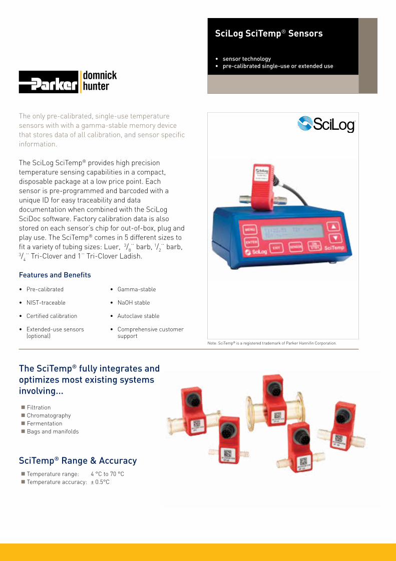
The only pre-calibrated, single-use temperature sensors with with a gamma-stable memory device that stores data of all calibration, and sensor specific information.
The SciLog SciTemp® provides high precision temperature sensing capabilities in a compact, disposable package at a low price point. Each sensor is pre-programmed and barcoded with a unique ID for easy traceability and data documentation when combined with the SciLog SciDoc software. Factory calibration data is also stored on each sensor’s chip for out-of-box, plug and play use. The SciTemp® comes in 5 different sizes to fit a variety of tubing sizes: Luer, 3/8¨ barb, 1/2¨ barb, 3/4¨ Tri-Clover and 1¨ Tri-Clover Ladish.
Features and Benefits
• Pre-calibrated
• NIST-traceable
• Certified calibration
• Extended-use sensors (optional)
• Gamma-stable
• NaOH stable
• Autoclave stable
• Comprehensive customer support
SciLog SciTemp® Sensors
• sensor technology• pre-calibrated single-use or extended use
Note: SciTemp® is a registered trademark of Parker Hannifin Corporation.
SciTemp® Range & Accuracy Temperature range: 4 °C to 70 °C Temperature accuracy: ± 0.5°C
The SciTemp® fully integrates and optimizes most existing systems involving...
Filtration Chromatography Fermentation Bags and manifolds

SciLog SciTemp® Sensors
Sensor SpecificationsSterilizability Can be sanitized IPA 70% NaOH (0.1N - 1.0N) Autoclavable: (1x) Gamma stable: 25-45 kGy
Material, Fluid Contact Medical grade polysulfone Meets USP Class VI and FDA 21CFR177.1520 All wetted materials are made of animal-free compounds
Sensor Type Thermistor Epoxy coated 2252 Ohms
Sensor Microchip EPROM Stored sensor ID and calibration factor
Sensor Connector and Cables Dust and water proof IP67
Size, Part Codes and Specifications
Monitor SpecificationsSensor Inputs Up to two simultaneously
Sensor Readout T1 and T2 Differential temperature (DT)
Analog Outputs 4-20 mA outputs for T1 and T2 18 bit resolution
Digital Output RS-232
Alarm Outputs 3 TTL switches User-selectable hi/lo pressure limit settings for T1, T2 and DT
Power Supply 115/230 VAC
Luer 3/8¨ Barb
1/2¨ Barb 3/4¨ Tri-Clover 1¨ Tri-Clover ‘Ladish’
SciTemp® Family
Connector Type Part Code (Packs of 5) Compatible Tubing Sizes Max. Flow Rate* Max. Pressure
Luer 080-799PSX-5 ID 0.03¨ to 0.31¨ 1 L / min 60 psi3/8¨ Barb 080-794PSX-5 ID 0.31¨ to 0.38¨ 8 L / min 60 psi1/2¨ Barb 080-795PSX-5 ID 0.50¨ 17 L / min 60 psi
3/4¨ Tri-Clover (TC) 080-796PSX-5 Tubing with 3/4¨ TC 31 L / min 60 psi
1¨ Tri-Clover ‘Ladish’ 080-797PSX-5 Tubing with 1¨ TC Ladish 60 L / min 60 psi
* Maximum flow rate @ 1 psi
DS_P_12_01/14 Rev. 1DParker domnick hunter has a continuous policy of product development and although the Company reserves the right to change specifications, it attempts to keep customers informed of any alterations. This publication is for general information only and customers are requested to contact our Process Filtration Sales Department for detailed information and advice on a products suitability for specific applications. All products are sold subject to the company’s Standard conditions of sale.
Euro
pe: ✆
+44
(0)1
91 4
1051
21
dhp
roce
ss@
park
er.c
om -
Nor
th A
mer
ica:
✆ +
1 60
8 82
4 05
00
dhp
sale
s.na
@pa
rker
.com
w
ww
.par
ker.c
om/d
hsin
gleu
se
Description Part Code
SciTemp® Sensor Monitor 080-790 (110V)081-790 (220V)
Sensor Cable (Sensor to Monitor) - 6 ft 090-0491
Sensor Cable (Sensor to Monitor)- 12 ft 090-0491-12

The HarvestClear™ Filtration System is a complete solution for cell culture harvest that provides fast, automated clarification of bioreactor outputs up to 20L. The system integrates SciLog fluid handling and pressure sensing expertise with the filtration excellence of Parker domnick hunter.
Simply connect your bioreactor to the sterile, ready-to-use filtration manifold, comprised of Parker domick hunter filters and SciPres® pressure sensors. Filtration is controlled by the FilterTec™ software-driven laboratory-scale normal flow filtration (NFF) system, teamed with a SciPres® pressure monitor. Three single-use filtration manifold sizes are available to clarify high cell density bioreactor outputs from 1L to 20L. The system can be connected to an optional WeighStation™ holding a single-use sterile bioprocess container to provide filtrate quantitation and precision flow metering.
Features and Benefits
• Walk-away automation reduces hands-on time, and optimizes filtration outputs.
• In-line SciPres® pressure sensors coupled with FilterTec™ controller ensure operator safety.
• Fully assembled, sterile filtration manifolds are ready-to-use with pre-flushed filters.
• Three filter manifold sizes to handle high density cell concentrations from 1-20L.
• Sterile single-use bioprocess containers are also available.
HarvestClear™ Filtration System
• intelligent bioprocessing system• automated bioreactor clarification
Single-Use Filtration ManifoldsThe three sizes of single-use, sterile filtration manifolds are gamma irradiated and are comprised of the pre-flushed filters indicated, with Luer connectors, tubing and SciPres® pressure sensors. Sterile single-use bioprocess containers to collect the filtrate are available separately.
Bioreactor Output
PROCLEAR GF(Prefiltration)
PROPOR HC (Sterilizing-Grade)
1-5L 10¨ 10¨
5-10L 20¨ 10¨
10-20L 30¨ 10¨
Walk-Away AutomationThe FilterTec™ controller offers four operational modes, constant rate, constant pressure, R/P Stat and manual modes. Using input from the in-line SciPres® pressure sensors, the FilterTec™ controller automatically adjusts and documents prefilter back pressure, as well as permeate flow rate to optimize filtration speed and maximize filter throughput. User selectable alarms allow automatic stopping once a given filter back pressure or minimum filtrate flow rate is reached. The patented R/P Stat Method has been proven to increase filter throughput by up to 30%. The automatic documentation and alarm /pump stop settings allow the user to focus on other tasks while the system is running. Integration of a balance with the system enables gravimetric end point control.
Increased SafetyThe automated HarvestClear™ Filtration System also increases operator safety. The FilterTec™ controller can be programmed to shut down at a maximum pressure, ensuring no damage to the filters or manifold, which could otherwise lead to operator injury, or potent proteins being discharged into the working environment.
Note: HarvestClear™, FilterTec™ and SciPres® are trademarks of Parker Hannifin Corporation.

Ordering Information
HarvestClear™ Filtration System
R/P Stat ModeThe FilterTec™ controller incorporates the patented R/P Stat Method, an innovation which offers significant improvements in filter output. The R/P Stat Method enables constant pressure or constant rate NFF via a pump / monitor PID loop including disposable inline pressure sensors. This is done by selecting three simple process variables including initial flow rate, maximum inlet pressure and minimum flow rate. By using the R/P Stat Method, the FilterTec™ controller operates at constant rate until it reaches the maximum pressure, then the controller switches to constant pressure and dynamically adjusts the flow rate as the membrane begins to foul. This allows additional product to pass through the filter and is shown graphically in Figure 1.
DS_P_29_07/13 Rev. 1BParker domnick hunter has a continuous policy of product development and although the Company reserves the right to change specifications, it attempts to keep customers informed of any alterations. This publication is for general information only and customers are requested to contact our Process Filtration Sales Department for detailed information and advice on a products suitability for specific applications. All products are sold subject to the company’s Standard conditions of sale.
18 -
16 -
14 -
12 -
10 -
8 -
6 -
4 -
2 -
0 -
- 25
- 20
- 15
- 10
- 5
- 00 200 400 600 800 1000 1200
Pum
p R
ate
(ml/
min
)
Pre
ssur
e (p
si)
Time (sec)
Pump Rate vs Time Pressure vs Time
Const. Rate Region Const. Pressure Region
Figure 1 - Dead-end filtration by R/P Stat Method
HarvestClear™ Filtration System ComponentsThe complete HarvestClear™ Filtration System solution consists of a programmable fluid handling system and a single-use filtration manifold. The system and manifolds are ordered separately.
HarvestClear™ Fluid Handling System FilterTec™ controller with a 600RPM motor and 1081 pump head SciPres® pressure sensor monitor Communication cables SciDoc data acquisition software
Filter Manifold Components 1 x PROCLEAR GF 5 µm glass-fibre prefilter 1 x PROPOR HC 0.2 µm polyethersulphone high capacity sterilizing-grade membrane filter 2 x SciPres® pre-calibrated pressure sensors (1¨ Tri-Clover) 1 x set of platinum-cured #17 silicone tubing (1/4¨ I.D, 3/8¨ O.D.) Luer connectors at each end, with sealing cups; bagged and zip-tied
FilterTec™ Specifications Dimension / Weight: Width: 5.75¨ (146 mm) Height: 8.5¨ (2126 mm) Depth: 11¨ (279 mm): 14 lbs (6.4 Kg) Enclosure & Rating: 16 Ga, aluminium baked epoxy blue 4-40dC, 0-100% Humidity Pressure Sensors: Accommodates up to three (3) disposable pressure sensors. The calibrated pressure range is 0 - 60 psi. Any point within this range can be recalibrated using an external pressure reference source. Power: 115 / 220-240 VAC, 60 / 50 Hz, 75 Watts, double fused: T1AL 250V (CE: IR35A 250VAC) Motor / Encoder: 600 RPM, 30 VDC, 3.8A, 100 ppr I/O Ports: Male DB9 scale connections (RS-232), female DB9 printer or PC connection (RS-232), external IO DB37 connector, 1 TTL input, 4 TTL output, 3 4-20mA Operational Mode: Constant rate, constant pressure, R/P Stat and manual mode Pump Head: 1081 flow rate (ml/min): 0.03 – 1515 Pressure: 25 psi continuous, 45 psi max.
Accessories Single-use bioprocess containers WeighStation™
Specifications
975-30 - 0
Code
0 1
Electricity Output
120 VAC 220 VAC
HarvestClear™ Fluid Handling System
Volume | Prefilter | Sterilizing Filter
1 - 5L 10¨ 5µm PROCLEAR GF 10¨ 0.2µm PROPOR HC 5 -10L 20¨ 5µm PROCLEAR GF 10¨ 0.2µm PROPOR HC 10 -20L 30¨ 5µm PROCLEAR GF 10¨ 0.2µm PROPOR HC
975-300-0
Code
CH2 CH10 CH20
-
HarvestClear™ Filtration System Manifolds
Please contact your local Parker domnick hunter representative to discuss alternative configurations for your system.
Euro
pe: ✆
+44
(0)1
91 4
1051
21
dhp
roce
ss@
park
er.c
om -
Nor
th A
mer
ica:
✆ +
1 60
8 82
4 05
00
dhp
sale
s.na
@pa
rker
.com
w
ww
.par
ker.c
om/d
hsin
gleu
se

The SciLog ChemTec™ is a high precision metering system that provides application specific automation for chemical and biological application.
The precision metering is achieved by using high resolution optical motor encoders for volumetric applications as well as connection to a balance for gravimetric applications. Applications range from programmable dispensing strategies, reactor biomass and pH maintenance, analog control, as well as solution weight maintenance or diafiltration control.
The automatic documentation and alarm / pump stop settings allow the user to focus on other tasks while the system is running. Programmable end points ensure the system ceases operation when run stops command or application target endpoints are reached. The ChemTec™ is available with peristaltic, piston and magnetic gear models. When sold with SciDoc software or a printer, documentation capabilities include 10 real-time filtration parameters.
Features and Benefits
• Volumetric or gravimetric operation
• Compatible with most 3rd party balances
• Real-time data collection
• Dispense accuracy <0.5% error
• Intuitive application interface
• Safe, walk-away systems operation
SciLog ChemTec™
• intelligent bioprocessing system• metering system
Metering The ChemTec™ provides user-definable feed either by volume or by weight. Volumes are calculated by a high resolution optical encoder or if connected to an electronic scale, the ChemTec™ becomes a self-calibrating metering system. The feed rates are executed on a user-programmable time schedule.
Linear and exponential feed gradients are readily implemented from the ChemTec™ front panel or programs can be prepared, stored and transferred from a PC.
Applications
Pump Rate (ml/min) vs. Time (hours)
120
100
80
60
40
20
0
Pum
p R
ate
(ml/
min
)
0 2 4 6 8 10 12 14 16
Time (hrs)
ChemTec™ - Mass Flow Feed Program000 START Start of ChemTec™ Program001 CW Clockwise Motor Direction002 RUN Pump Motor Turned ON003 RATE=35.60 Start Pump Rate, gr./min004 EXTP=96:48 Pump Rate is Increased from005 TIME=04:00 35.60 to 96.48 over 4 hours006 EXTP=97.65 Pump Rate is Increased from007 TIME=11:00 96.48 to 97.65 over 11 hours008 STOP Pump Stop009 COUNT=1 Program Runs on time010 END End of Program
Note: ChemTec™ is a trademark of Parker Hannifin Corporation.
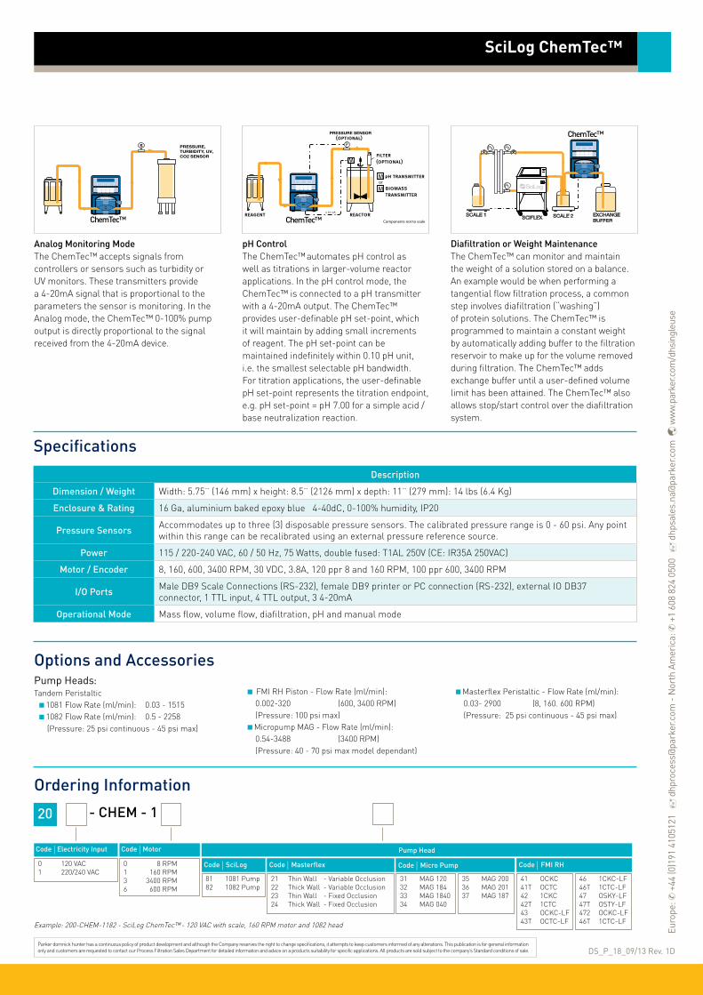
Ordering Information
20 - CHEM - 1
Code | Electricity Input
0 120 VAC 1 220/240 VAC
Code | Motor
0 8 RPM 1 160 RPM 3 3400 RPM 6 600 RPM
SciLog ChemTec™
Example: 200-CHEM-1182 - SciLog ChemTec™ - 120 VAC with scale, 160 RPM motor and 1082 head
SpecificationsDescription
Dimension / Weight Width: 5.75¨ (146 mm) x height: 8.5¨ (2126 mm) x depth: 11¨ (279 mm): 14 lbs (6.4 Kg)
Enclosure & Rating 16 Ga, aluminium baked epoxy blue 4-40dC, 0-100% humidity, IP20
Pressure Sensors Accommodates up to three (3) disposable pressure sensors. The calibrated pressure range is 0 - 60 psi. Any point within this range can be recalibrated using an external pressure reference source.
Power 115 / 220-240 VAC, 60 / 50 Hz, 75 Watts, double fused: T1AL 250V (CE: IR35A 250VAC)
Motor / Encoder 8, 160, 600, 3400 RPM, 30 VDC, 3.8A, 120 ppr 8 and 160 RPM, 100 ppr 600, 3400 RPM
I/O Ports Male DB9 Scale Connections (RS-232), female DB9 printer or PC connection (RS-232), external IO DB37 connector, 1 TTL input, 4 TTL output, 3 4-20mA
Operational Mode Mass flow, volume flow, diafiltration, pH and manual mode
Options and Accessories
Analog Monitoring ModeThe ChemTec™ accepts signals from controllers or sensors such as turbidity or UV monitors. These transmitters provide a 4-20mA signal that is proportional to the parameters the sensor is monitoring. In the Analog mode, the ChemTec™ 0-100% pump output is directly proportional to the signal received from the 4-20mA device.
pH ControlThe ChemTec™ automates pH control as well as titrations in larger-volume reactor applications. In the pH control mode, the ChemTec™ is connected to a pH transmitter with a 4-20mA output. The ChemTec™ provides user-definable pH set-point, which it will maintain by adding small increments of reagent. The pH set-point can be maintained indefinitely within 0.10 pH unit, i.e. the smallest selectable pH bandwidth. For titration applications, the user-definable pH set-point represents the titration endpoint, e.g. pH set-point = pH 7.00 for a simple acid /base neutralization reaction.
Diafiltration or Weight MaintenanceThe ChemTec™ can monitor and maintain the weight of a solution stored on a balance. An example would be when performing a tangential flow filtration process, a common step involves diafiltration (“washing”) of protein solutions. The ChemTec™ is programmed to maintain a constant weight by automatically adding buffer to the filtration reservoir to make up for the volume removed during filtration. The ChemTec™ adds exchange buffer until a user-defined volume limit has been attained. The ChemTec™ also allows stop/start control over the diafiltration system.
Parker domnick hunter has a continuous policy of product development and although the Company reserves the right to change specifications, it attempts to keep customers informed of any alterations. This publication is for general information only and customers are requested to contact our Process Filtration Sales Department for detailed information and advice on a products suitability for specific applications. All products are sold subject to the company’s Standard conditions of sale.
Pump Head
Code | SciLog
81 1081 Pump 82 1082 Pump
Code | Masterflex
21 Thin Wall - Variable Occlusion 22 Thick Wall - Variable Occlusion 23 Thin Wall - Fixed Occlusion 24 Thick Wall - Fixed Occlusion
Code | Micro Pump
31 MAG 120 32 MAG 184 33 MAG 1840 34 MAG 040
35 MAG 200 36 MAG 201 37 MAG 187
Code | FMI RH
41 OCKC 41T OCTC 42 1CKC 42T 1CTC 43 OCKC-LF 43T OCTC-LF
46 1CKC-LF 46T 1CTC-LF 47 OSKY-LF 47T OSTY-LF 472 OCKC-LF 46T 1CTC-LF
PRESSURE,TURBIDITY, UV, CO2 SENSOR
S
Pump Heads: Tandem Peristaltic 1081 Flow Rate (ml/min): 0.03 - 1515 1082 Flow Rate (ml/min): 0.5 - 2258 (Pressure: 25 psi continuous - 45 psi max)
FMI RH Piston - Flow Rate (ml/min): 0.002-320 (600, 3400 RPM) (Pressure: 100 psi max) Micropump MAG - Flow Rate (ml/min): 0.54-3488 (3400 RPM) (Pressure: 40 - 70 psi max model dependant)
Masterflex Peristaltic - Flow Rate (ml/min): 0.03- 2900 (8, 160. 600 RPM) (Pressure: 25 psi continuous - 45 psi max)
DS_P_18_09/13 Rev. 1D
ChemTec™
ChemTec™ ChemTec™
Euro
pe: ✆
+44
(0)1
91 4
1051
21
dhp
roce
ss@
park
er.c
om -
Nor
th A
mer
ica:
✆ +
1 60
8 82
4 05
00
dhp
sale
s.na
@pa
rker
.com
w
ww
.par
ker.c
om/d
hsin
gleu
se

The SciLog FilterTec™ is an automated laboratory scale normal flow filtration (NFF) system that monitors, adjusts and documents filter back pressure and filtrate.
The result is a system that can optimize filtration parameters, maximize filter throughput and can also be used as a tool to evaluate / compare different filters by calculating Vmax. The system also offers the patented R/P Stat (rate/pressure) method, which has been proven to increase filter throughput up to 30%.
The automatic documentation and alarm / pump stop settings allow the user to focus on other tasks while the system is running. Programmable end points ensure the system stops operating when a given back pressure, filtrate rate or total filtrate limit has been reached. When sold with SciDoc software, documentation capabilities include collection of 15 real-time filtration parameters. The FilterTec™ is also an integral component in the HarvestClear™ Filtration System, a complete solution for clarifying bioreactor outputs up to 20L.
Features and Benefits• Safe, walk-away system
operation
• Filterability studies and Vmax determination
• Real-time data collection of 15 filtration parameters
• Increased NFF filter efficiency up to 30%
• 3 pressures sensor connections for serial or parallel filter trains
• Compatible with all filters
• Optional scale enables gravimetric control
SciLog FilterTec™ / FilterTec™ Plus
• intelligent bioprocessing system• dead-end single / multi-filtration system
FilterTec™ PlusTriple your NFF productivity with the FilterTec™ Plus and enjoy the same features of the SciLog FilterTec™ for filterability studies, filter size determination and filter scale-up. The FilterTec™ Plus has expanded upon the capabilities of the FilterTec™ to communicate with up to three electronic balances and control three pump heads simultaneously. This product allows for testing of three identical NFF filters at the same rates or three different filters at the same pressure. Parallel processing of a solution through three filters provides statistical verification of filter capacity. The FilterTec™ Plus is compatible with all manufacturers' filters.
Note: FilterTec™ is a trademark of Parker Hannifin Corporation.

Performance Characteristics
Fig. 1 - Normal Flow Filtration by R/P Stat Method
18
16
14
12
10
8
6
4
2
0
Pum
p R
ate
(ml/
min
)
2.5
2.0
1.5
1.0
0.5
0
Diff
eren
tial P
ress
ure
(psi
)
0 200 400 600 800 1000 1200
Time (sec)
Fig. 2 - FilterTec™ R/P Programmable ModeTime-Programmable Pump Pressure
Pum
p Pr
essu
re (p
si)
Cellulose Acetate Membrane FilterPorosity: 0.45 micron, Filter Area: 17.3 cm2
Solution: Fat Free Skim Milk, 20 x Diluted
25
20
15
10
5
00 5.0 10.0 15.0 20.0 25.0
Time (min)
Fig. 3 - V max: NFF Capacity Determination
Tim
e / W
eigh
t (se
c/gr
)
Cellulose Actate Membrane Discs, 47 mmPorsity: 0.45 micron Surrogate Sample; 30 x Skim Milk,
Pump: #14 Silicone Tubing, FilterTec™ ‘P-State Mode’, 20 psi
1.2
1.0
0.8
0.6
0.4
0.2
00 50 100 150 200 250 300 350
Time (sec)
Const. Rate Region Const. Pressure Region
Slope = 0.002961 1/gr1/Slope = V max. = 338ml
Pump Rate vs TimePressure vs Time Pressure vs Time
V maxDI Water
SciLog FilterTec™ / FilterTec™ Plus
Applications
SpecificationsDescription
Dimension / Weight Width: 5.75¨ (146 mm) x Height: 8.5¨ (2126 mm) x Depth: 11¨ (279 mm): 14 lbs (6.4 Kg)
Enclosure & Rating 16 Ga, aluminium baked epoxy blue 4-40dC, 0-100% humidity
Pressure Sensors Accommodates up to three (3) disposable pressure sensors. The calibrated pressure range is 0 - 60 psi. Any point within this range can be recalibrated using an external pressure reference source.
Power 115 / 220-240 VAC, 60 / 50 Hz, 75 Watts, double fused: T1AL 250V (CE: IR35A 250VAC)
Motor / Encoder 8, 160, 600 RPM, 30 VDC, 3.8A, 120 ppr 8 and 160 RPM, 100 ppr 600 RPM
I/O Ports Male DB9 scale connections (RS-232), female DB9 printer or PC connection (RS-232), external IO DB37 connector, 1 TTL input, 4 TTL output, 3 4-20mA
Operational Mode Constant rate (can be used to perform R/P Stat Method), constant pressure, R/P programmable and manual mode
Normal Flow Filtration (NFF)The FilterTec™ uses a pressure sensor and scale feedback to perform normal flow operations by constant rate or constant pressure. The end point controls ensure the system shuts off when a user defined maximum filter pressure, minimum filtrate rate or maximum filtrate limit is reached.
Normal Flow Filtration (NFF) - OptimizedThe FilterTec™ achieves optimized normal flow operations by utilizing the patented R/P Stat Method. This automated procedure maintains a selected pump rate until a user-defined upper pressure limit has been attained as a result of filter plugging. The system automatically switches from a constant rate to a constant pressure fluid delivery (see Fig. 1). The pump continuously reduces the flow rate to maintain the pressure across the filter until a user-defined minimum filtrate rate is attained. This method allows full utilization of the existing filter capacity and is accompanied by a significant increase in total filter throughput upwards of 30% compared to constant pressure or constant flow throughput data.
Filterability StudiesThe FilterTec™ is capable of simultaneously monitoring three pressure points. This capability is particularly useful in monitoring the pressure differentials of multiple filters in a serial or a parallel filter train. Excessive pressure build-up across a filtration stage element typically indicates the need for a larger porosity and/or a larger area filter element. The FilterTec™’s R/P programmable mode allows you to modify the pump rate and/ or pressure over a selected time interval, in a stair-step (Step) or ramped (Scan) manner, (see Fig. 2) until the user defined filtrate weight has been attained.
Vmax DeterminationWhen used with an electronic scale, the FilterTec™ collects and documents the filtrate weight in the constant pressure, constant rate or R/P Stat Method. The parameter T/W (Time / Filtrate Weight) is plotted against time. The inverse of the resulting slope represents Vmax. The FilterTec™ reports the instantaneous Vmax from the slope of the neighboring data points. (see Fig. 3).

Ordering Information
20 - FLTR -
Code | Electricity Input
0 120 VAC 1 220 VAC
Code |Scale
5 None 7 Scale Included
Code | Motor
0 8 RPM 1 160 RPM 6 600 RPM
Code | Pump Head
81 1081 Pump 82 1082 Pump
SciLog FilterTec™ / FilterTec™ Plus
Example: 200-FLTR-7181 - SciLog FilterTec™ - 120 VAC with scale, 160 RPM motor and 1081 head
FilterTec™ Pump Heads:SciLog TandemPressure: 25 psi continuous 45 psi max.1081 Flow Rate (ml/min): 0.03 - 1515 1082 Flow Rate (ml/min): 0.5 - 2258
FilterTec™ Plus Pump Heads:MasterFlex Easyload II3 heads (thin walled tubing) with 8 RPM motor. Flow rate*: 0.03 to 24 ml/min.3 heads (thin walled tubing) with 160 RPM motor. Flow rate*: 0.5 to 554 ml/min.
3 heads (thin walled tubing) with 600 RPM motor. Flow rate*: 2 to 1515 ml/min.3 heads (thick walled tubing) with 600 RPM motor. Flow rate*: 59 to 2258 ml/min.
Electronic Scales 8 RPM System: 2100g capacity x 0.01g resolution160 or 600 RPM System: 8100g capacity x 0.1g resolution
Options and Accessories
DS_P_19_07/13 Rev. 1CParker domnick hunter has a continuous policy of product development and although the Company reserves the right to change specifications, it attempts to keep customers informed of any alterations. This publication is for general information only and customers are requested to contact our Process Filtration Sales Department for detailed information and advice on a products suitability for specific applications. All products are sold subject to the company’s Standard conditions of sale.
20 - FLTR -
Code | Electricity Input
0 120 VAC 1 220 VAC
Code |Scale
6 None 8 Scale Included
Code | Motor
0 8 RPM 1 160 RPM 6 600 RPM
Code | Pump Head
21 Easyload II, thin walled tubing 22 Easyload II, thick walled tubing
Example: 200-FLTR-8121- SciLog FilterTec™ Plus - 120 VAC with scale, 160 RPM motor and 3 MasterFlex Easyload II heads for thin walled tubing.
FilterTec™
FilterTec™ Plus
Euro
pe: ✆
+44
(0)1
91 4
1051
21
dhp
roce
ss@
park
er.c
om -
Nor
th A
mer
ica:
✆ +
1 60
8 82
4 05
00
dhp
sale
s.na
@pa
rker
.com
w
ww
.par
ker.c
om/d
hsin
gleu
se
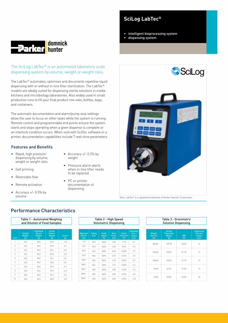
The SciLog LabTec® is an automated laboratory scale dispensing system by volume, weight or weight ratio.
The LabTec® automates, optimizes and documents repetitive liquid dispensing with or without in-line filter sterilization. The LabTec® models are ideally suited for dispensing sterile solutions in media kitchens and microbiology laboratories. Also widely used in small production runs to fill your final product into vials, bottles, bags, and containers.
The automatic documentation and alarm/pump stop settings allow the user to focus on other tasks while the system is running. Remote control and programmable end points ensure the system starts and stops operating when a given dispense is complete or an interlock condition occurs. When sold with SciDoc software or a printer, documentation capabilities include 7 real-time parameters.
Features and Benefits• Rapid, high prevision
dispensing by volume, weight or weight ratio
• Self priming
• Reversible flow
• Remote activation
• Accuracy +/- 0.5% by volume
• Accuracy +/- 0.3% by weight
• Pressure alarm alerts when in-line filter needs to be replaced
• PC or printer documentation of dispensing
SciLog LabTec®
• intelligent bioprocessing system• dispensing system
Note: LabTec® is a registered trademark of Parker Hannifin Corporation.
Performance Characteristics
Table 1 - Automated Weighing and Dilution of Food Samples
Table 2 - High Speed Volumetric Dispensing
Table 3 - Gravimetric Solution Dispensing
Trial
SampleWeight
(g)
TheoreticalDiluentWeight
(g)
Actual DiluentWeight
(g)Errors
(g)
1 10.0 90.0 90.0 0.0
2 10.0 90.0 89.9 -0.1
3 10.0 90.0 90.1 +0.1
4 10.0 90.0 89.8 -0.2
5 10.0 90.0 90.1 +0.1
6 10.0 90.0 90.0 +0.1
7 10.0 90.0 89.9 -0.1
8 10.0 90.0 90.2 +0.2
9 10.0 90.0 90.1 +0.1
10 10.0 90.0 89.8 -0.2
Dispensed Volume
(ml)
TubingSize
PumpSpeed
(%)
SlowFactor
(ml)
TypicalPrecision
(%)
DispensingTime /Aliquot
(sec)
5.0 #15 100% 2.50 1.7% 2.1
10.0 #15 100% 2.50 0.5% 2.0
25.0 #15 100% 2.50 0.20% 2.7
25.0 #24 100% 4.75 0.15% 2.9
50.0 #24 100% 4.75 0.50% 3.9
100.0 #24 100% 4.75 0.35% 6.3
100.0 #35 100% 5.00 <0.5% 4.5
200.0 #35 100% 5.00 <0.5% 6.0
300.0 #35 100% 5.00 <0.5% 12.0
WeightEntered
(g)
AvergeDispensed
Weight(g)
RSD(%)
Dispensing Time perAliquot
(sec)
200.00 199.95 0.03% 16
150.00 150.01 0.11% 14
100.00 100.01 0.11% 13
50.00 49.96 0.18% 12
25.00 25.05 0.25% 10

Ordering Information
20 - LABT-1
Code | Electricity Input
0 120 VAC 1 220 VAC
Code | Motor
0 8 RPM 1 160 RPM 3 3400 RPM 6 600 RPM
Pump Head
Code | SciLog
SciLog LabTec®
Example: 200-LABT-1181 - SciLog LabTec® - 120 VAC,160 RPM motor and 1081 head
Applications
Pump Heads: Tandem Peristaltic 1081 flow rate (ml/min): 0.03 - 1515 1082 flow rate (ml/min): 0.5 - 2258 (Pressure: 25 psi continuous - 45 psi max)
FMI RH piston: 0.002-320 (600, 3400 RPM) (Pressure: 100 psi max) Micropump MAG: 0.54-3488 (3400 RPM) (Pressure: 40 - 70 psi max[model dependant] )
Masterflex peristaltic: 0.03- 2900 (8, 160. 600 RPM) (Pressure: 25 psi continuous - 45 psi max)
Specifications
Options and Accessories
The LabTec® significantly increases the productivity of any microbiology laboratory. The dispensing system automates weighing and diluting of food samples, in preparation for bacteriological analysis. Only an approximate sample size is needed. The LabTec® dispenser calculates and rapidly dispenses the media required to achieve a user-selected diluent factor. See Table 1. Costly and time-consuming autoclaving of media is avoided with in-line filter sterilization of diluents using a filter capsule. A disposable pressure sensor monitors filter backpressure and provides an alarm signal when a failing sterilizing filter (high backpressure) needs to be replaced. An optional printer or PC hook-up automatically documents all sample and diluent weights. The LabTec® dispenser improves the speed, precision and accuracy of the entire sample preparation process by automating the weighing, dilution and documentation process.
Parker domnick hunter has a continuous policy of product development and although the Company reserves the right to change specifications, it attempts to keep customers informed of any alterations. This publication is for general information only and customers are requested to contact our Process Filtration Sales Department for detailed information and advice on a products suitability for specific applications. All products are sold subject to the company’s Standard conditions of sale.
LabTec Performance Data: Automated Weighing and Dilution of Food Samples
Trial#
SampleWeight
TheoreticalDiluent Weight
ActualDiluent Weight
Error(grams)
1 10.0gr . 90.0gr 90.0gr 0.02 10.0 90.0 89.9 - 0.13 10.0 90.0 90.1 + 0.14 10.0 90.0 89.8 - 0.25 10.0 90.0 90.1 + 0.16 10.0 90.0 90.0 + 0.17 10.0 90.0 89.9 - 0.1 8 10.0 90.0 90.2 + 0.2 9 10.0 90.0 90.1 + 0.110 10.0 90.0 89.8 - 0.2 _________ A VE: 89.99 SD: 0.14 RSD: 0.15%
LabTec Dispensing Parameters: Weight Factor = 9.00, Slow Factor = 25gr, Pump Rate = 50% #24 Silicone pump tubing was used for all dispensed aliquots. All solutions were dispensed through a Pall SuporCap 50 sterilizing �lter. Cycle Time: 25 sec.; Diluent Dispensing Time:14 sec.
The LabTec® Smart Dispensing System is capable of high speed, high precision batch dispensing. The LabTec® comes with a 1082 Tandem peristaltic pump head. Up to 10 different dispensing volumes can be stored and easily retrieved for quick batch volume dispensing. An optional sterilizing filter and disposable pressure sensor provide for in-line buffer sterilization and reliable detection of filter plug-up conditions. Typical performance results including dispensing times are summarized in Table 2. The LabTec® is easy to calibrate. A stored calibration curve is provided for each pump head/pump tubing combination. From a stored menu, you select the pump tubing you have installed in the LabTec®. For high accuracy dispensing applications, you may want to use the LabTec®’s single-point re-cal feature.
In this configuration, the LabTec® is connected to an electronic scale for high accuracy filling applications. A sterilizing filter and a disposable pressure transducer provide a safe and effective in-line filter sterilization capability. The LabTec® continuously monitors the filter backpressure and alarms when a user-defined pressure level has been exceeded, which indicates a filter plug-up condition. See Table 3. The high dispensing accuracy is achieved by reducing the pump rate as final target weight is being approached. The slow-down avoids overshooting the target weight. After slow-down, the LabTec® pump stops briefly when 99% of the final target weight has been dispensed. The electronic scale is allowed to come to a steady-state readout and the LabTec® slowly starts up again to dispense the remaining solution.
4. Biopharmaceutical GMP Fil l ing Application: High Accuracy Dispensing with In-Line Filter Sterilization
LabTec Performance Data: Gravimetric Solution Dispensing
Weight Entered
Avg. DispensedWeight
RSD(%)
Dispensing TimePer Aliquot
200.00 gr 199.95 gr 0.03% 16 Sec 150.00 gr 150.01 gr 0.11% 14 Sec 100.00 gr 100.01 gr 0.11% 13 Sec 50.00 gr 49.96 gr 0.18% 12 Sec 25.00 gr 25.05 gr 0.25% 10 Sec
Note: The above data set was generated with a LabTec CP 200 , 600 RPM Motor, Tandem 1082 peristaltic pump head, and #24 (thick-walled) pump tubing. A Mettler PG-5002-S, readability 0.01 gram, was connected to the LabTec.Note: Distilled water was used as a diluent; �ve (5) separate measurements were made for each of the sample weights. Each aliquot was dispensed onto the balance. The average Delivered Diluent Weight and the Relative Standard Deviation (RSD) and the Dispensing Time per Aliquot are summarized.
Description
Dimension / Weight Width: 5.75¨ (146 mm) x height: 8.5¨ (2126 mm) x depth: 11¨ (279 mm): 14 lbs (6.4 kg)
Enclosure & Rating 16 Ga, aluminium baked epoxy blue 4-40dC, 0-100% humidity, IP20
Pressure Sensors Accommodates one (1) disposable pressure sensor. The calibrated pressure range is 0 - 60 psi. Any point within this range can be recalibrated using an external pressure reference source.
Power 115 / 220-240 VAC, 60 / 50 Hz, 75 Watts, double fused: T1AL 250V (CE: IR35A 250VAC)
Motor / Encoder 8, 160, 600, 3400 RPM, 30 VDC, 3.8A, 100 ppr
I/O Ports Male DB9 scale connections (RS-232), female DB9 printer or PC connection (RS-232), external IO DB37 connector, 1 TTL input, 4 TTL output, 3 4-20mA
Operational Mode Dispense by volume, weight or weight ratio. Store up to 10 programs per mode. Pump re-calibration.
81 1081 Pump 82 1082 Pump
Code | Masterflex
21 Thin Wall 22 Thick Wall 62 Hi Performance L/S
Code | Micro Pump
31 MAG 120 32 MAG 201 33 MAG 1840 34 MAG 040
35 MAG 200 36 MAG 201 37 MAG 187
Code | FMI RH
41 OCKC 42 1CKC
2. High Speed, High Precision Volumetric Batch Dispensing
LabTec Performance Data: High Speed Volumetric Dispensing
DispensedVolume (ml)
TubingSize:
PumpSpeed:
SlowFactor:
TypicalPrecision:
DispensingTime/Aliquot
5.00 ml #15 100% 2.50 ml 1.7% 2.1 Sec 10.00 ml #15 100% 2.50 ml 0.5% 2.0 Sec 25.00 ml #15 100% 2.50 ml 0.20% 2.7 Sec
25.00 ml #24 100% 4.75 ml 0.15% 2.9 Sec 50.00 ml #24 100% 4.75 ml 0.50% 3.9 Sec 100.00 ml #24 100% 4.75 ml 0.35% 6.3 Sec
100.00 ml #35 100% 5.00 ml <0.5 % 4.5 Sec 200.00 ml #35 100% 5.00 ml <0.5 % 6.0 Sec 450.00 ml #35 100% 5.00 ml <0.5 % 12.0 Sec
Note: This performance data was generated with a 600 RPM pump motor and Tandem 1082 peristaltic pump head. The pump tubing was made of Silicone
Weighing, Dilution and Sterilization Precision Batch Dispensing Fast, Accurate Dispensing and Sterilization
DS_P_17_07/13 Rev. 1C
LabTec®
LabTec® LabTec®
Euro
pe: ✆
+44
(0)1
91 4
1051
21
dhp
roce
ss@
park
er.c
om -
Nor
th A
mer
ica:
✆ +
1 60
8 82
4 05
00
dhp
sale
s.na
@pa
rker
.com
w
ww
.par
ker.c
om/d
hsin
gleu
se

The SciLog MabTec® is an automated high density cell culture system.
The MabTec® high density cell culture system is a fully automated gravimetric bioreactor maintenance system. Its capabilities include automated feed, harvest or recirculation in fully disposable or hybrid bioreactor flow paths. The system also includes the ability to conduct unattended bioreactor inoculations, bolus feed and/or pump flow reversals (to prevent filter fouling) all on one unit with run times from hours to months.
The MabTec® is available with a choice of pump heads and can feed bioreactor sizes from 50mL to 2000L. The MabTec® is engineered to fit seamlessly with any bioreactor and enhance its performance. A laboratory scale, available separately, must be connected to use the MabTec®’s gravimetric features.
Features and Benefits
• Safe, walk-away system operation
• Maintains a steady state bioreactor weight / volume within +/- 0.5%
• Real-time data collection with optimization tools
• Small, lightweight and mobile
• Works with any bioreactor
• Eliminates bioractor addition errors
• Reduces aggregation of cells in the perfusion filter
• Intuitive application interface
SciLog MabTec®
• intelligent bioprocessing system• automated high density cell culture system
Note: MabTec® is a registered trademark of Parker Hannifin Corporation.
MabTec® motor size, pump head and tubing recommendationsvs reactor size and reactor exchanges per day
8 RPM with 1081 and #13 tubing8 RPM with 1082 and #15 tubing8 RPM with 1082 and #24 tubing160 RPM with 1081 and #14 tubing160 RPM with 1081 and #16 tubing160 RPM with 1082 and #15 tubing160 RPM with 1082 and #24 tubing600 RPM with 1082 and #15 tubing600 RPM with 1082 and #24 tubing600 RPM with 1082 and #35 tubing
Reactor Volume Size
0.05 0.25 0.5 1 1.5 2 2 2.2 3 3 4 4 5 5 10 20 50 100 250 500 1000 2000
#Ex
chan
ge p
er d
ay
1 0.03 0.17 0.35 0.69 1.04 1 2 2 3 3 7 14 35 69 174 347 694 1389
2 0.07 0.35 0.69 1 2 3 3 4 6 6 7 14 28 69 139 347 694 1389
3 0.10 0.52 1 2 3 4 4 5 6 8 8 10 10 21 42 104 208 521 1042 2083
4 0.14 0.69 1 3 4 6 6 6 8 8 11 11 14 14 28 56 139 278 694 1389
5 0.17 0.87 2 3 5 7 7 8 10 10 14 14 17 17 35 69 174 347 868 1736
10 0.35 2 3 7 10 14 14 15 21 21 28 28 21 35 69 139 347 694 1736
15 0.52 3 5 10 16 21 21 23 31 31 42 52 104 208 521 1042
20 0.69 3 7 14 21 28 31 63 56 69 139 278 694 1389
#13 #15 #24 #16 #14 #15 #14 #16 #24 #15 #24 #15 #24 #35
8 RPM 160 RPM 8 160 RPM 600 RPM
1081 1082 1081 1082 1081 1082
*Flow rates in grams per minute
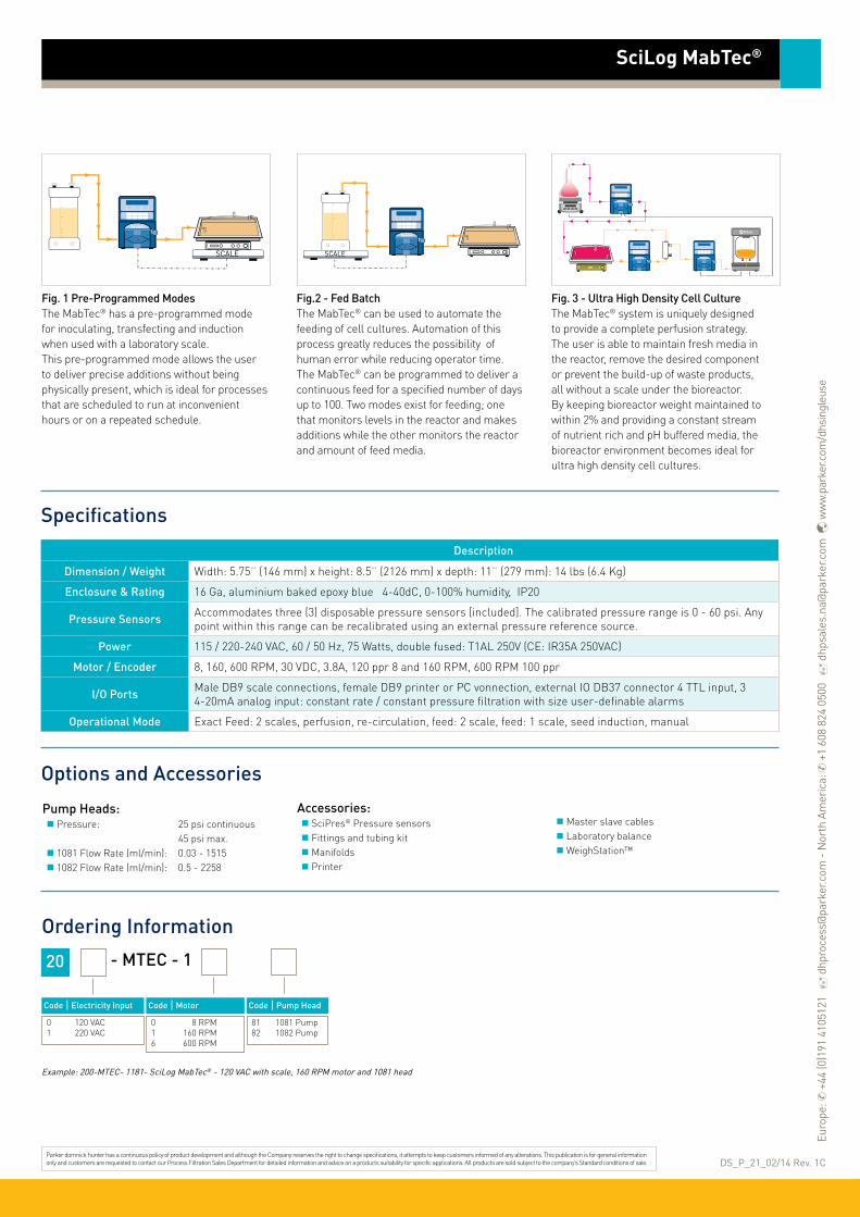
Ordering Information
20 - MTEC - 1
Code | Electricity Input
0 120 VAC 1 220 VAC
SciLog MabTec®
Example: 200-MTEC- 1181- SciLog MabTec® - 120 VAC with scale, 160 RPM motor and 1081 head
Specifications
Description
Dimension / Weight Width: 5.75¨ (146 mm) x height: 8.5¨ (2126 mm) x depth: 11¨ (279 mm): 14 lbs (6.4 Kg)
Enclosure & Rating 16 Ga, aluminium baked epoxy blue 4-40dC, 0-100% humidity, IP20
Pressure Sensors Accommodates three (3) disposable pressure sensors [included]. The calibrated pressure range is 0 - 60 psi. Any point within this range can be recalibrated using an external pressure reference source.
Power 115 / 220-240 VAC, 60 / 50 Hz, 75 Watts, double fused: T1AL 250V (CE: IR35A 250VAC)
Motor / Encoder 8, 160, 600 RPM, 30 VDC, 3.8A, 120 ppr 8 and 160 RPM, 600 RPM 100 ppr
I/O Ports Male DB9 scale connections, female DB9 printer or PC vonnection, external IO DB37 connector 4 TTL input, 3 4-20mA analog input: constant rate / constant pressure filtration with size user-definable alarms
Operational Mode Exact Feed: 2 scales, perfusion, re-circulation, feed: 2 scale, feed: 1 scale, seed induction, manual
Options and Accessories
Fig. 1 Pre-Programmed ModesThe MabTec® has a pre-programmed mode for inoculating, transfecting and induction when used with a laboratory scale. This pre-programmed mode allows the user to deliver precise additions without being physically present, which is ideal for processes that are scheduled to run at inconvenient hours or on a repeated schedule.
Fig.2 - Fed BatchThe MabTec® can be used to automate the feeding of cell cultures. Automation of this process greatly reduces the possibility of human error while reducing operator time. The MabTec® can be programmed to deliver a continuous feed for a specified number of days up to 100. Two modes exist for feeding; one that monitors levels in the reactor and makes additions while the other monitors the reactor and amount of feed media.
Fig. 3 - Ultra High Density Cell CultureThe MabTec® system is uniquely designed to provide a complete perfusion strategy. The user is able to maintain fresh media in the reactor, remove the desired component or prevent the build-up of waste products, all without a scale under the bioreactor. By keeping bioreactor weight maintained to within 2% and providing a constant stream of nutrient rich and pH buffered media, the bioreactor environment becomes ideal for ultra high density cell cultures.
DS_P_21_02/14 Rev. 1CParker domnick hunter has a continuous policy of product development and although the Company reserves the right to change specifications, it attempts to keep customers informed of any alterations. This publication is for general information only and customers are requested to contact our Process Filtration Sales Department for detailed information and advice on a products suitability for specific applications. All products are sold subject to the company’s Standard conditions of sale.
Pump Heads: Pressure: 25 psi continuous 45 psi max. 1081 Flow Rate (ml/min): 0.03 - 1515 1082 Flow Rate (ml/min): 0.5 - 2258
Accessories: SciPres® Pressure sensors Fittings and tubing kit Manifolds Printer
Master slave cables Laboratory balance WeighStation™
Code | Motor
0 8 RPM 1 160 RPM 6 600 RPM
Code | Pump Head
81 1081 Pump 82 1082 Pump
Euro
pe: ✆
+44
(0)1
91 4
1051
21
dhp
roce
ss@
park
er.c
om -
Nor
th A
mer
ica:
✆ +
1 60
8 82
4 05
00
dhp
sale
s.na
@pa
rker
.com
w
ww
.par
ker.c
om/d
hsin
gleu
se
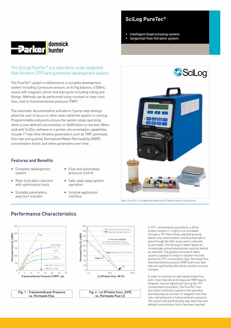
The SciLog PureTec® is a laboratory-scale tangential flow filtration (TFF) and parameter development system.
The PureTec® system is delivered as a complete development system including 3 pressure sensors, an 8.1kg balance, a 500mL vessel with magnetic stirrer and startup kit including tubing and fittings. Methods can be performed using constant or step cross flow, inlet or transmembrane pressure (TMP). The automatic documentation and alarm / pump stop settings allow the user to focus on other tasks while the system is running. Programmable end points ensure the system stops operating when a user defined concentration or diafiltration is reached. When sold with SciDoc software or a printer, documentation capabilities include 17 real-time filtration parameters such as TMP, permeate flow rate and quantity, Normalized Water Permeability (NWP), concentration factor, and other parameters over time.
Features and Benefits
• Complete development system
• Real-time data collection with optimization tools
• Scalable parameters, easy tech transfer
• Flow and automated pressure control
• Safe, walk away system operation
• Intuitive application interface
SciLog PureTec®
• intelligent bioprocessing system• tangential flow filtration system
Note: PureTec® is a registered trademark of Parker Hannifin Corporation.
Performance Characteristics
Fig. 1 - Transmembrane Pressure vs. Permeate Flux
300
250
200
150
100
50
0
Perm
eate
Flu
x (J
), LM
2H
0 5 10 15 20 25 30 35
Transmembrane Pressure (TMP)*, psi
Fig. 2 - Ln [Protein Conc, (CP)]vs. Permeate Flux (J)
Perm
eate
Flu
x (J
), LM
2H
180
160
140
120
100
80
60
40
20
01.0 10.0 100.0
Ln (Protein Conc. Wt %)
In TFF, concentration procedures, a dilute protein solution (~1.0 g/L) is re-circulated, through a TFF filter whose selected porosity allows only solvent (water) and dissolved salt to pass through the filter pores and is collected as permeate. The removal of water leaves an increasingly concentrated protein solution behind as retentate. The gradual removal of water causes a gradual increase in solution viscosity during the TFF concentration step. Permeate flux, transmembrane pressure (TMP) and cross flow rate are significantly affected by solution viscosity changes.
In order to maintain an optimal permeate flux, both cross flow rate and measured TMP require frequent, manual adjustment during the TFF concentration procedure. The PureTec® has the control methods to perform the operation automatically via constant or stepped cross flow rate, inlet pressure or transmembrane pressure. The system will automatically stop when the user defined concentration factor has been reached.
WFI
3 wt% Protein
5 wt%
8 wt%
*TMP = [(P1 + P2) / 2] - P3
TMP max ~ 17 psi
J = Flux = K Ln [Cp/Cm]Cp = Protein Concentration in SolutionCm = Protein Concentration at membrane
Slope 1 = k’ = Mass Transfer Co-efficient
Slope 2 = k¨
Cm
Retentate Flow Rate: 80 ml/minRetentate Flow Rate: 50 ml/min

Ordering Information
20 - PURE-
Code |Electricity Input
0 120 VAC 1 220 VAC
Code | Scale
7 Scale Included
Code |Motor
0 8 RPM 1 160 RPM 6 600 RPM
Code |Pump Head
SciLog
SciLog PureTec®
Example: 200-PURE-7181 - SciLog PureTec® - 120 VAC with scale, 160 RPM motor and 1081 head
Applications
Pump Heads: SciLog Tandem Pressure: 25 psi continuous 45 psi max.1081 flow rate (ml/min): 0.03 - 1515 1082 flow rate (ml/min): 0.5 - 2258
Accessories Ohaus balance 8100g 0.1g resolution Vessel 500 mL Magnetic mixer
Pressure sensors (3x)Fittings & tubing kit
Specifications
Options and Accessories
In the constant pump rate or pressure modes, you can implement your selected pump rate or pressures and use some or all of five alarm conditions. The pump rate or pressures can be increased or decreased “on-the-fly” without stopping the pump action.
In the constant rate mode, increasing the feed rate in a stepwise fashion and simultaneously monitoring the permeate collection rate allows you to readily determine the optimal feed rate with the highest permeate yield (See figure 2). In the constant pressure mode, increasing the trans-membrane pressure (TMP) in a step-wise fashion and simultaneously monitoring the permeate collection rate allows you to determine the optimal TMP with the highest permeate yield (See figure 1).
Parker domnick hunter has a continuous policy of product development and although the Company reserves the right to change specifications, it attempts to keep customers informed of any alterations. This publication is for general information only and customers are requested to contact our Process Filtration Sales Department for detailed information and advice on a products suitability for specific applications. All products are sold subject to the company’s Standard conditions of sale.
In diafiltration procedures, a protein solution is “washed”, i.e. de-salted, using an exchange buffer to remove undesirable electrolyte (dissolved salt). The concentrated protein solution is re-circulated, through a TFF filter whose selected porosity allows only the undesirable electrolyte to pass through the filter pores, which is collected as permeate. The permeate volume (undesirable electrolyte) that has been removed from the concentrated protein solution (retentate) is replaced with an (desirable) exchange buffer. In constant volume diafiltration or “washing” procedure, the collected electrolyte is automatically replaced by an equal volume of exchange buffer. Approximately ten (10x) volume exchanges are typically required for substantial removal of undesirable electrolyte from the concentrated protein solution.
Diafiltration via suction:For small volumes a SciLog pressure vessel stored with buffer can be connected to the secondary inlet port on the retentate vessel. While keeping a closed system the retentate vessel will automatically draw out buffer to replace the salt and solvent that has been removed by the filter. The process will continue until the PureTec® has reached its programmable end points.
Diafiltration via ChemTec®:For larger volumes the SciLog ChemTec® system and an appropriately sized balance will monitor and maintain the fluid in the PureTec®’s retentate vessel. The ChemTec® will maintain the level until a user defined volume exchange has been reached.
Description
Dimension / Weight Width: 5.75¨ (146 mm) x height: 8.5¨ (2126 mm) x depth: 11¨ (279 mm): 14 lbs (6.4 kg)
Enclosure & Rating 16 Ga, aluminium baked epoxy blue 4-40dC, 0-100% humidity, IP20
Pressure Sensors Accommodates three (3) disposable pressure sensors. The calibrated pressure range is 0 - 60 psi. Any point within this range can be recalibrated using an external pressure reference source.
Power 115 / 220-240 VAC, 60 / 50 Hz, 75 Watts, double fused: T1AL 250V (CE: IR35A 250VAC)
Motor / Encoder 8, 160, 600 30 VDC, 3.8A, 120 ppr 8 & 160 RPM, 100 ppr 600 RPM
I/O PortsMale DB9 scale connections (RS-232), female DB9 printer or PC connection (RS-232), external IO DB37 connector, 1 TTL input, 4 TTL output, 3 4-20mA Analog Input: Constant rate / constant pressure filtration with size user-definable alarms
Operational Mode Constant pump rate, constant inlet or transmembrane pressure (TMP)
81 1081 Pump 82 1082 Pump
Concentration Diafiltration via Suction Diafiltration via ChemTec®
DS_P_20_07/13 Rev. 1C
Components not to scale
Components not to scale
Components not to scale
Components not to scale
CHEMTEC PURETECChemTec® PureTec®
Euro
pe: ✆
+44
(0)1
91 4
1051
21
dhp
roce
ss@
park
er.c
om -
Nor
th A
mer
ica:
✆ +
1 60
8 82
4 05
00
dhp
sale
s.na
@pa
rker
.com
w
ww
.par
ker.c
om/d
hsin
gleu
se

The SciLog SciFlex® NFF is a proven semi-automated single-use platform to use in discovery to production-scale normal flow applications.
The SciFlex® NFF automated single-use normal flow filtration (NFF) system automatically monitors, adjusts and documents pressures and flow rate to optimize processing times, and maximize filter life and efficiency. Using the onboard sensors and automation we eliminate the need for constant monitoring during production runs. The SciFlex® system’s ‘Open Architecture’ design means there is no need to change existing filter or membrane types / manufacturers because this system will work with any supplier’s filter.
Via a colour, touch screen and pre-installed operational software, users have the ability to execute a normal flow filtration process via four different control methods. User-selectable end points and alarms enable walk-away operation and ensure safe, consistent process performance. Patented, proprietary technology enables automated system response to in-line SciPres® pressure sensor feedback and the selectable maintenance of a user-definable flow rate, inlet filter pressure, or both. The system can optimize your filtration throughput by up to 30% while communicating real time process parameters via OPC to a plant historian. Up to two optional integrated scales can be used to deliver filtration precision by gravimetrically controlling operations.
Features and Benefits•Walk-away automation
improves filter throughput using patented rate pressure controlled feed
•Options for fully disposable, semi-disposable, or stainless CIP flowpaths
•Configurable for multiple or flexible processes
•Accommodates any commercially available filter
•Touch-screen interface with optional OPC connectivity for process documentation or remote control
•Mobile and compact base
•User configurable alarms and interlocks
•Optional integrated scale for highly accurate filtration endpoints
SciLog SciFlex® NFF
• intelligent bioprocessing system• semi-automated NFF
Note: SciFlex® and SciPres® are registered trademarks of Parker Hannifin Corporation.
The SciFlex® NFF semi-automated system offers four modes of process control:Constant Rate NFF: Maintain rate, monitor pressure. The system will ensure pressure does not exceed a high limit set point.Constant Pressure NFF: Maintain pressure, monitor rate. The system will ensure rate does not exceed a minimum set point.R/P Stat Method: The system maintains a constant rate, monitoring pressure until a selectable pressure is reached. At this pressure, the system immediately switches to constant pressure, monitoring rate (see Figure 1.) until a minimum set point is reached. Manual Operation: User definable motor set point
Batch control is ensured:Recipes can be conveniently stored and recalled at the time of execution to save time and reduce the risk of parameters being installed incorrectly.Up to 10 sequential steps can be stored to provide continuous processing.
Applications
Viral filtration
Cell harvesting
Chromatography column loading
Clarification and sterilization
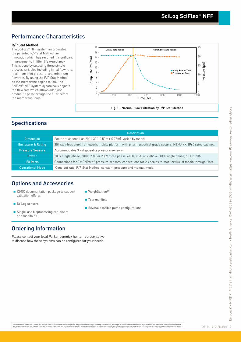
Ordering Information
SciLog SciFlex® NFF
Specifications
Description
Dimension Footprint as small as 20” x 30” (0.50m x 0.76m), varies by model.
Enclosure & Rating 304 stainless steel framework, mobile platform with pharmaceutical grade casters, NEMA 4X, IP65 rated cabinet.
Pressure Sensors Accommodates 3 x disposable pressure sensors.
Power 208V single phase, 60Hz, 20A; or 208V three phase, 60Hz, 20A; or 220V +/- 10% single phase, 50 Hz, 20A.
I/O Ports Connections for 3 x SciPres® pressure sensors, connections for 2 x scales to monitor flux of media through filter.
Operational Mode Constant rate, R/P Stat Method, constant pressure and manual mode.
DS_P_14_01/14 Rev. 1CParker domnick hunter has a continuous policy of product development and although the Company reserves the right to change specifications, it attempts to keep customers informed of any alterations. This publication is for general information only and customers are requested to contact our Process Filtration Sales Department for detailed information and advice on a products suitability for specific applications. All products are sold subject to the company’s Standard conditions of sale.
Please contact your local Parker domnick hunter representative to discuss how these systems can be configured for your needs.
R/P Stat MethodThe SciFlex® NFF system incorporates the patented R/P Stat Method, an innovation which has resulted in significant improvements in filter life expectancy. This is done by selecting three simple process variables including initial flow rate, maximum inlet pressure, and minimum flow rate. By using the R/P Stat Method, as the membrane begins to foul, the SciFlex® NFF system dynamically adjusts the flow rate which allows additional product to pass through the filter before the membrane fouls.
Options and AccessoriesIQ/OQ documentation package to support validation efforts
SciLog sensors
Single-use bioprocessing containers and manifolds
WeighStation™
Test manifold
Several possible pump configurations
Performance Characteristics
18 -
16 -
14 -
12 -
10 -
8 -
6 -
4 -
2 -
0 -
- 25
- 20
- 15
- 10
- 5
- 00 200 400 600 800 1000 1200
Pum
p R
ate
(ml/
min
)
Pre
ssur
e (p
si)
Time (sec)
Pump Rate vs Time Pressure vs Time
Const. Rate Region Const. Pressure Region
Fig. 1 - Normal Flow Filtration by R/P Stat Method
Euro
pe: ✆
+44
(0)1
91 4
1051
21
dhp
roce
ss@
park
er.c
om -
Nor
th A
mer
ica:
✆ +
1 60
8 82
4 05
00
dhp
sale
s.na
@pa
rker
.com
w
ww
.par
ker.c
om/d
hsin
gleu
se

The SciLog SciFlex® TFF is an automated tangential flow filtration system.
The SciFlex® TFF is a semi-automated, single-use tangential flow filtration (TFF) system that automatically monitors, adjusts and documents pressures and flow rate to optimize filtration speed and maximize filter life and efficiency, eliminating the need for constant monitoring during runs.
The SciFlex® system’s ‘Open Architecture’ design means there is no need to change filter or membrane types because this system will work with any supplier’s filter. An integrated scale can be used to gravimetrically control concentration, while the inline SciPres® pressure sensors monitor transmembrane pressure to prevent extreme pressure over the membrane.
Features and Benefits• Automated onboard
filtration methods
• OPC data collection via ethernet, or on a USB flash memory in CSV format
• Integrated SciPres® pressure sensors
• Safe, walk-away system operation
• Intuitive application interface
• ‘Open Architecture’ engineering enables this system to work with most filters or membranes
SciLog SciFlex® TFF
• intelligent bioprocessing system• semi-automated TFF
Note: SciFlex® and SciPres® are registered trademarks of Parker Hannifin Corporation.
The SciFlex® TFF semi-automated system offers three modes of process control:Constant Rate TFF: Maintain rate, monitor pressure. The system will ensure pressure does not exceed set point.Constant Pressure TFF: Maintain pressure, monitor rate. The system will ensure rate does not exceed set point.Manual Operation: User definable motor set point.Constant Rate / Constant Pressure TFF is available as an optional upgrade: Maintain rate set by user as well as transmembrane pressure by modulating a nonproduct contact proportional valve in the retentate line. The system will ensure pressure does not exceed set point.
Batch control is ensured:Recipes can be conveniently stored and recalled at the time of execution to save time and reduce the risk of parameters being installed incorrectly.Up to 10 sequential steps can be stored to provide continuous processing.
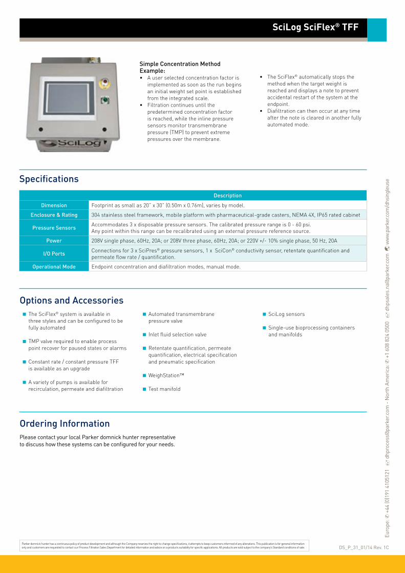
Ordering Information
SciLog SciFlex® TFF
Specifications
Description
Dimension Footprint as small as 20” x 30” (0.50m x 0.76m), varies by model.
Enclosure & Rating 304 stainless steel framework, mobile platform with pharmaceutical-grade casters, NEMA 4X, IP65 rated cabinet
Pressure Sensors Accommodates 3 x disposable pressure sensors. The calibrated pressure range is 0 - 60 psi. Any point within this range can be recalibrated using an external pressure reference source.
Power 208V single phase, 60Hz, 20A; or 208V three phase, 60Hz, 20A; or 220V +/- 10% single phase, 50 Hz, 20A
I/O Ports Connections for 3 x SciPres® pressure sensors, 1 x SciCon® conductivity sensor, retentate quantification and permeate flow rate / quantification.
Operational Mode Endpoint concentration and diafiltration modes, manual mode.
DS_P_31_01/14 Rev. 1CParker domnick hunter has a continuous policy of product development and although the Company reserves the right to change specifications, it attempts to keep customers informed of any alterations. This publication is for general information only and customers are requested to contact our Process Filtration Sales Department for detailed information and advice on a products suitability for specific applications. All products are sold subject to the company’s Standard conditions of sale.
Please contact your local Parker domnick hunter representative to discuss how these systems can be configured for your needs.
Simple Concentration Method Example:• A user selected concentration factor is
implemented as soon as the run begins an initial weight set point is established from the integrated scale.
• Filtration continues until the predetermined concentration factor is reached, while the inline pressure sensors monitor transmembrane pressure (TMP) to prevent extreme pressures over the membrane.
• The SciFlex® automatically stops the method when the target weight is reached and displays a note to prevent accidental restart of the system at the endpoint.
• Diafiltration can then occur at any time after the note is cleared in another fully automated mode.
Options and AccessoriesThe SciFlex® system is available in three styles and can be configured to be fully automated
TMP valve required to enable process point recover for paused states or alarms
Constant rate / constant pressure TFF is available as an upgrade
A variety of pumps is available for recirculation, permeate and diafiltration
Automated transmembrane pressure valve
Inlet fluid selection valve
Retentate quantification, permeate quantification, electrical specification and pneumatic specification
WeighStation™
Test manifold
SciLog sensorsSingle-use bioprocessing containers and manifolds
Euro
pe: ✆
+44
(0)1
91 4
1051
21
dhp
roce
ss@
park
er.c
om -
Nor
th A
mer
ica:
✆ +
1 60
8 82
4 05
00
dhp
sale
s.na
@pa
rker
.com
w
ww
.par
ker.c
om/d
hsin
gleu
se

Accelerate to market and reduce your purification costs with the SciLog SciPure® TFF and NFF Systems.
The SciPure® system’s user-friendly interface and menu-driven operation with data acquisition (21 CFR Part 11) make them ideal for GMP manufacturing. Systems come with a comprehensive documentation package that drastically reduces validation times.
Semi-manual to fully-automated operation makes tech transfer seamless and accommodates existing processes. The SciPure® ‘Open Architecture’ design allows you to use any manufacturer’s filters.
Contact Parker domnick hunter to discuss how the SciPure® system can be quickly configured to accommodate your TFF and NFF needs. We have one of the shortest lead times in the industry.
Features and Benefits• Maintains optimal TFF
or NFF conditions with fully-automated control
• User-friendly with full colour graphical display, touch-screen and menu-driven operation
• User definable recipes and parameters, or real-time control
• Reduces purification costs by optimizing, controlling and documenting your processes
• Batch method generator
• Configured single-use or stainless steel manifolds with minimum hold-up volume
• Can be used with any manufacturer’s filters
• Ethernet, OPC
• User administrative controls
SciLog SciPure®
• fully-automated bioprocessing system• GMP-ready TFF and NFF
Note: SciPure® and SciPres® are registered trademarks of Parker Hannifin Corporation.
Applications
Concentration
Diafiltration
Clarification / sterilization
Media and buffer preparation
Fluid transfer
Mixing
Chromatography and column loading
Harvest
Desalting
Viral filtration

Ordering Information
SciLog SciPure®
Specifications
Description
Dimension 50” L x 30” W x 48” H (127cm L x 76.2cm W x 121.9cm H) other configurations available as system requires
Enclosure & Rating 304 Stainless Steel framework, Mobile platform with pharmaceutical grade casters, NEMA 4X, IP65 rated cabinet
Pneumatics Compressed air, Nitrogen @ 35 psi
Power 208VAC 1/3 Ph, 480VAC 3Ph
I/O Ports Standard connections for 3 SciPres® pressure sensors, 1 SciCon® conductivity sensor, retentate quantification and permeate flow rate / quantification. Additional I/O and digital communications available.
Operational Mode Endpoint concentration and diafiltration modes, manual mode
International Quality Standards RoHS, CE, ETL, CSA and UL
Plant Communications OPC DA 2.0
DS_P_15_07/13 Rev. 1BParker domnick hunter has a continuous policy of product development and although the Company reserves the right to change specifications, it attempts to keep customers informed of any alterations. This publication is for general information only and customers are requested to contact our Process Filtration Sales Department for detailed information and advice on a products suitability for specific applications. All products are sold subject to the company’s Standard conditions of sale.
Please contact your local Parker domnick hunter representative to discuss how these systems can be configured for your needs.
Configured Single-Use ManifoldsIndividualized, pre-packaged and presterilized manifolds not only reduce cleaning and cleaning validation times, but also reduce setup time by engineering your application and ensuring installation success. You can set up recurring orders for just-in-time delivery of manifolds or they can be stored in secure inventory and atmosphere controlled warehouses. All flowpath designs are individually configured and drawn by in-house engineers.
Integrated with filters, sensors, and bioprocess containers, single-use manifolds can be pre-assembled and sterilized with SciLog SciPres® pressure sensors, Parker domnick hunter filters (or filters of your choice), as well as single-use bioreactor, collection or hanging bioprocess containers.
Manifolds for TFFManifolds can be provided pre-assembled with sensors and integrated filter plate insert for flat sheet membranes or gamma-stable hollow fiber filters.
Euro
pe: ✆
+44
(0)1
91 4
1051
21
dhp
roce
ss@
park
er.c
om -
Nor
th A
mer
ica:
✆ +
1 60
8 82
4 05
00
dhp
sale
s.na
@pa
rker
.com
w
ww
.par
ker.c
om/d
hsin
gleu
se

The SciLog WeighStation™ family is an assortment of mobile, compact, bioprocessing container holders with integrated scales for gravimetric fluid handling.
The SciLog WeighStation™ serves as a flexible platform that provides quantitative and reproducible fluid measurement for a wide range of upstream and downstream applications.
With several biocontainer options, there is a WeighStation™ to match your process. Systems are available to accommodate 5L to 200L bags and are available with optional display heads.
All SciLog WeighStations™ can also be readily integrated into Parker domnick hunter or other manufacturers’ systems, making them a convenient gravimetric solution for existing processes. The WeighStation™ can interface with your data historian, local display, printer or spreadsheet.
Features and Benefits
• Mobile design / small footprint
• Gravimetric application control
• Optional displays
• Multiple configurations
• Operator friendly design
• Easily integrates with existing systems
SciLog WeighStation™
• gravimetric fluid handling platform• mobile bioprocessing workstation
Note: WeighStation™ is a trademark of Parker Hannifin Corporation.
WeighStation™ Configuration
Maximum Load Practical Limits Resolution Footprint
WeighStation™ 50Kg* < 49.99Kg 10g 29¨x 29¨
WeighStation™ Dual 100Kg* < 49.99Kg each 10g 29¨x 29¨
WeighStation™ Triple 150Kg* < 49.99Kg each 10g 29¨x 29¨
WeighPro™ 50Kg* < 49.99Kg 10g 29¨x 29¨
WeighCart™ 100 200Kg < 100L or < 100Kg 2g 24¨ x 36¨
WeighCart™ 200 300Kg < 200L or < 200Kg 3g 30¨ x 42¨
WeighSmart™ 50Kg each* < 49.99Kg 10g 12¨ x 28¨
* Recommended volume < 35L per bioprocess container

Ordering Information
900 - WSTN -
Code | Model
SINGLE WeighStation™ DUAL WeighStation™ Dual TRP WeighStation™ Triple PRO WeighPro™ CART 100 WeighCart™ 100 CART 200 WeighCart™ 200 RCART WeighSmart™
SciLog WeighStation™
Example: 900-WSTN - SINGLE SciLog WeighStation™
Specifications
Description
Materials of Construction 304 Stainless Steel, Pharmaceutical Grade Casters
Power US 120 VAC 1 Phase 60 HZ < 2 AMP: EU 230 +/- 10% 50 HZ <2 AMP
Communications IP 65 Communication Ports, RS232, Analog, RS485, Mettler SISC, Modbus, Profibus, ethernet: custom options available
WeighStation™The WeighStation™ is a vertical bioprocess container (BPC) holder with gravimetric feedback. The base model can accommodate one to three (3) 50Kg single-use hanging BPC. Even when fully loaded, the four locking castors enable a single user to move the unit from location to location with ease. This mobile hanging balance eliminates the tiresome balancing of BPCs on mobile carts and provides safe complete drainage or 100% sample recovery without requiring a second operator to hold the BPC.
DS_P_16_10/13 Rev. 1BParker domnick hunter has a continuous policy of product development and although the Company reserves the right to change specifications, it attempts to keep customers informed of any alterations. This publication is for general information only and customers are requested to contact our Process Filtration Sales Department for detailed information and advice on a products suitability for specific applications. All products are sold subject to the company’s Standard conditions of sale.
WeighCart™WeighCart™ is a mobile BPC with gravimetric feedback that easily accommodates 100L or 200L bioprocess containers. These two options are typically assembled with a 150Kg balance or a 300Kg balance. Stock system include a worktop and supports to mount a SciLog laboratory automated liquid handling system. Other accessories and balance options are available.
WeighPro™The WeighPro™ is a mobile bioprocessing workstation that can be configured to any application.The unit includes a 50Kg vertical bioprocess container holder with gravimetric feedback and optional adjustable filter, tubing, sensor and pump mounts. The system can be quickly configured for various bioprocessing projects without sacrificing space or capital.
WeighSmart™The WeighSmart™ is a vertical BPC holder with gravimetric feedback that can be used with a GE ReadyKart. The units may also be integrated on your existing systems or wall mounted in your laboratory. The WeighSmart™ can handle up 50Kg and includes a height adjustable foot for easy integration and added stability.
Model Options
ModelsEu
rope
: ✆ +
44 (0
)191
410
5121
dhp
roce
ss@
park
er.c
om -
Nor
th A
mer
ica:
✆ +
1 60
8 82
4 05
00
dhp
sale
s.na
@pa
rker
.com
w
ww
.par
ker.c
om/d
hsin
gleu
se

mitos-P is a nonreinforced platinum-cured silicone tubing with lot and part number etched directly onto the tubing. mitos-P is well suited for performance in applications requiring use of peristaltic pumps and / or molded assemblies.
This precision tubing is manufactured with an automated control system that repeatedly measures the inner bore and wall thickness, maintaining a 0.002¨ to 0.008¨ tolerance.
mitos-P
Features and Benefits
• Lot number, tube ID and wall thickness marked on each tube
• Tightest wall tolerance available (0.002¨ to 0.008¨)
• Ideal for molding with other silicones into manifold assemblies (Ts, Ys, crosses, elbows and reducers)
• Certificate of conformance included with each order
• Manufactured in ISO Class 7 cleanroom
• Can be chemically or mechanically cleaned and can be sterilized by chemicals, autoclave or gamma-irradiation
• Available in four different wall thicknesses and internal diameters up to 1¨
• Platinum-cured silicone tubing• Ideal for manifold assemblies
Ideal for use in peristaltic pumps and molded assemblies
mitos-P is the preferred platinum-cured silicone tubing for use in peristaltic pumps and molded assemblies because of its consistency in dimensions. This consistency delivers optimum performance in both applications by providing steady flow rates during pumping and by ensuring better bonding during molding, giving greater integrity to the assembly.
Applications
Single-use applications
Molded manifold assemblies
Peristaltic pumps
Bioprocess container systems
Low pressure transfer lines
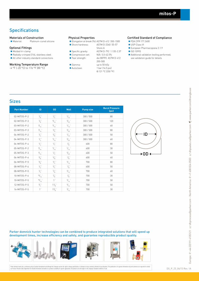
SpecificationsMaterials of Construction Material: Platinum-cured silicone
Optional Fittings Molded tri-clamp Radially-crimped 316L stainless steel All other industry standard connections
Working Temperature Range-4 °F (-20 °C) to 176 °F (80 °C)
Physical Properties Elongation at break (%): ASTM D-412 550-1500 Shore hardness: ASTM D-2240 55-57 Shore A Specific gravity: ASTM D-792 1.135-2.37 Compression set: N/A 5.0-42.5% Tear strength: die B(PPI) ASTM D-412 200-500 Gamma: up to 50 kGy Autoclave: 1 bar (14.5 psi) @ 121 °C (250 °F)
Certified Standard of Compliance FDA CFR 177.2600 USP Class VI European Pharmacopoeia 3.1.9 ISO 10993 Additional validation testing performed, see validation guide for details
mitos-P
Sizes
Part Number ID OD Wall Pump size Burst Pressure (psi)
02-MITOS-P-2 1/8¨1/4¨
1/16¨ 300 / 500 80
02-MITOS-P-3 1/8¨5/16¨
3/32¨ 300 / 500 120
03-MITOS-P-2 3/16¨5/16¨
1/16¨ 300 / 500 60
03-MITOS-P-3 3/16¨3/8¨
3/32¨ 300 / 500 80
04-MITOS-P-2 1/4¨3/8¨
1/16¨ 300 / 500 50
04-MITOS-P-3 1/4¨7/16¨
3/32¨ 300 / 500 60
04-MITOS-P-4 1/4¨1/7¨
1/8¨ 600 80
05-MITOS-P-2 5/16¨7/16¨
1/16¨ 600 30
05-MITOS-P-3 5/16¨1/2¨
3/32¨ 600 50
06-MITOS-P-4 3/8¨5/8¨
1/8¨ 600 60
06-MITOS-P-5 3/8¨3/4¨
3/16¨ 700 80
08-MITOS-P-4 1/2¨3/4¨
1/8¨ 600 50
08-MITOS-P-5 1/2¨7/8¨
3/16¨ 700 60
10-MITOS-P-4 10/16¨7/8¨
1/8¨ 700 30
10-MITOS-P-5 10/16¨ 1¨ 3/16¨ 700 50
12-MITOS-P-5 3/4¨ 11/8¨3/16¨ 700 50
16-MITOS-P-5 1¨ 13/8¨3/16¨ 700 30
OD
ID
DS_P_23_04/13 Rev. 1AParker domnick hunter has a continuous policy of product development and although the Company reserves the right to change specifications, it attempts to keep customers informed of any alterations. This publication is for general information only and customers are requested to contact our Process Filtration Sales Department for detailed information and advice on a products suitability for specific applications. All products are sold subject to the company’s Standard conditions of sale.
Parker domnick hunter technologies can be combined to produce integrated solutions that will speed up development times, increase efficiency and safety, and guarantee reproducible product quality.
Euro
pe: ✆
+44
(0)1
91 4
1051
21
dhp
roce
ss@
park
er.c
om -
Nor
th A
mer
ica:
✆ +
1 60
8 82
4 05
00
dhp
sale
s.na
@pa
rker
.com
w
ww
.par
ker.c
om/d
hsin
gleu
se

mitos-R is a platinum-cured silicone hose with polyester fibre braid reinforcement structure to maintain flexibility, withstand high pressure and resist kinking.
This hose can be molded with other silicones into manifold assemblies with molded tri-clamp, creating seamless and crevice-free fittings. It can also be used in radially-crimped hose assemblies.
mitos-R
Features and Benefits
• Lot number and customized information directly on hose with CLEAR-mark® label*
• Can be molded with other silicones into manifold assemblies (Ts, Ys, crosses, elbows and reducers)
• Animal derived component free
• Certificate of conformance with each order
• Manufactured in ISO Class 7 clean room
• Can be chemically or mechanically cleaned and can be sterilized by chemicals, autoclave or gamma-irradiation
• SIP / CIP capable
• Available with internal diameter up to 1¨
• Reinforced platinum-cured silicone tubing• Withstands high pressure, resists kinking
*CLEAR-mark® is a registered trademark of Integra Companies.
Molded silicone fittings
Molded silicone fittings are the ideal option when there is need for an easily cleanable assembly, or to reduce the risk of cross-contamination. In each molded fitting, the elastomer chains of the platinum-cured silicone are cross-linked to create a permanent molecular bond to the tubing. A special feature of our molded tri-clamp is an integrated gasket that, when connected to another fitting, eliminates 50% of the sealing faces creating seamless and crevice-free fittings. For extra support, we offer a full stainless steel or polysulfone back-up cup on the outside of each molded fitting. Our plastic back-up cups have a unique wraparound design that fully encases the tri-clamp mold.
Applications
Molded manifold assemblies
High pressure transfer lines
Single-use applications
Radially-crimped hose assemblies

SpecificationsMaterials of Construction Material: Platinum-cured silicone with fibre braid reinforcement
Available Fittings Molded tri-clamp Radially-crimped 316L stainless steel All other industry standard connections
Sterilization Gamma Irradiation: Maximum of 50 kGy Autoclave: 1 bar (14.5 psi) @ 121°C (250°F)
Physical Properties Elongation at break (%): ASTM D-412 425% Shore hardness: ASTM D-2240 60 Shore A Tear strength: ASTM D-412 100 die B (PPI) Tensile strength: 1200 psi General temperature range: -100°F (-73.3°C) to 302°F (150°C) Brittle temperature: -100°F (-73.3°C) Max. operating temperature: 400°F (204.4°C)
Certified Standard of Compliance FDA CFR 177.2600 USP Class VI European Pharmacopoeia 3.1.9 ISO 10993 Additional validation testing performed, see validation guide for details
mitos-R
Sizes
Part Number ID OD *Recommended working pressure (psi) @ 68 °F
Minimum burst pressure (psi) @ 68 °F
02-MITOS-R 1/8¨3/8¨ 175 700
03-MITOS-R 3/16¨ 0.462¨ 170 650
04-MITOS-R 1/4¨1/2¨ 160 575
06-MITOS-R 3/8¨5/8¨ 150 550
08-MITOS-R 1/2¨7/8¨ 140 420
10-MITOS-R 5/8¨ 1¨ 115 400
12-MITOS-R 3/4¨ 11/4¨ 90 350
16-MITOS-R 1¨ 13/8¨ 60 225OD
ID Polyester braid
DS_P_22_04/13 Rev. 1AParker domnick hunter has a continuous policy of product development and although the Company reserves the right to change specifications, it attempts to keep customers informed of any alterations. This publication is for general information only and customers are requested to contact our Process Filtration Sales Department for detailed information and advice on a products suitability for specific applications. All products are sold subject to the company’s Standard conditions of sale.
* Note: If part of a molded assembly, maximum operating pressure would change.
Parker domnick hunter technologies can be combined to produce integrated solutions that will speed up development times, increase efficiency and safety, and guarantee reproducible product quality.
Euro
pe: ✆
+44
(0)1
91 4
1051
21
dhp
roce
ss@
park
er.c
om -
Nor
th A
mer
ica:
✆ +
1 60
8 82
4 05
00
dhp
sale
s.na
@pa
rker
.com
w
ww
.par
ker.c
om/d
hsin
gleu
se

mitos-WCO is a platinum-cured silicone hose with multi-ply fibre braids, 316 stainless steel helical wire reinforcement and a convoluted exterior. The convoluted exterior provides excellent bend radius and resistance to kinking.
mitos-WCO
Features and Benefits
• Lot number and customized information directly on hose with CLEAR-mark® label*
• Animal derived component free
• Certificate of conformance with each order
• Smooth inner bore
• Superior bend radius and resistance to kinking
• Can be sterilized by autoclave or gamma-irradiation
• SIP / CIP capable
• Available with internal diameter up to 3¨
• Platinum-cured silicone hose, stainless steel wire reinforced, with convoluted exterior
• For high pressure or vacuum applications with excellent bend radius
*CLEAR-mark® is a registered trademark of Integra Companies.
Radially-crimped stainless steel
Parker domnick hunter offers a comprehensive line of industry standard connection options. All stainless steel fittings are 316 stainless steel and are available in an electropolished (<15 Ra) or standard machine finish (20 Ra). Our stainless steel fittings are manufactured in a U.S. based facility dedicated exclusively to fabricating sanitary fittings for the biotech industry. Parker domnick hunter fittings are unparalleled in material consistency, dimensions, surface finish, and craftsmanship. All fittings feature a heat identifier which allow them to be fully traceable. Styles include tri-clamp, elbow, NPT, flange, and other industry standard connections.
Applications
Hose assemblies
Bulk transfer lines
High pressure transfer lines
Vacuum applications
SIP / CIP carts
Load cells
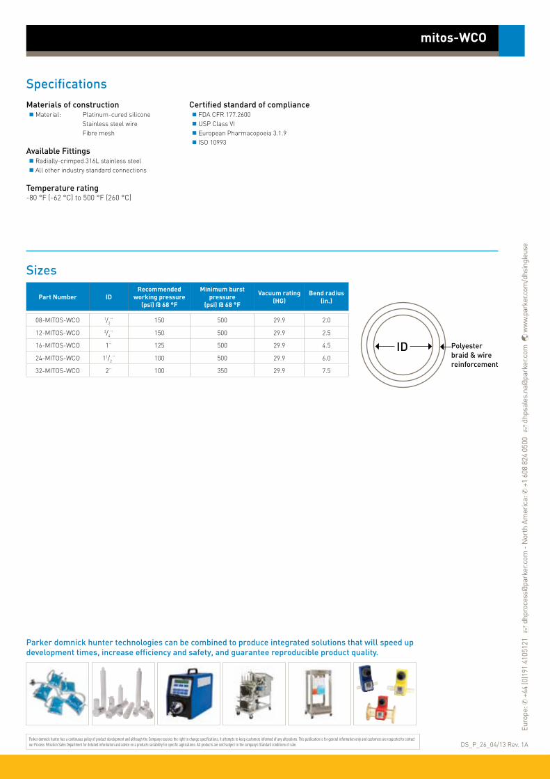
SpecificationsMaterials of construction Material: Platinum-cured silicone Stainless steel wire Fibre mesh
Available Fittings Radially-crimped 316L stainless steel All other industry standard connections
Temperature rating-80 °F (-62 °C) to 500 °F (260 °C)
Certified standard of compliance FDA CFR 177.2600 USP Class VI European Pharmacopoeia 3.1.9 ISO 10993
mitos-WCO
Sizes
ID Polyester braid & wire reinforcement
Part Number IDRecommended
working pressure (psi) @ 68 °F
Minimum burst pressure
(psi) @ 68 °F
Vacuum rating(HG)
Bend radius(in.)
08-MITOS-WCO 1/2¨ 150 500 29.9 2.0
12-MITOS-WCO 3/4¨ 150 500 29.9 2.5
16-MITOS-WCO 1¨ 125 500 29.9 4.5
24-MITOS-WCO 11/2¨ 100 500 29.9 6.0
32-MITOS-WCO 2¨ 100 350 29.9 7.5
DS_P_26_04/13 Rev. 1AParker domnick hunter has a continuous policy of product development and although the Company reserves the right to change specifications, it attempts to keep customers informed of any alterations. This publication is for general information only and customers are requested to contact our Process Filtration Sales Department for detailed information and advice on a products suitability for specific applications. All products are sold subject to the company’s Standard conditions of sale.
Parker domnick hunter technologies can be combined to produce integrated solutions that will speed up development times, increase efficiency and safety, and guarantee reproducible product quality.
Euro
pe: ✆
+44
(0)1
91 4
1051
21
dhp
roce
ss@
park
er.c
om -
Nor
th A
mer
ica:
✆ +
1 60
8 82
4 05
00
dhp
sale
s.na
@pa
rker
.com
w
ww
.par
ker.c
om/d
hsin
gleu
se

With custom-designed manifolds, Parker domnick hunter molds imagination into reality. Whether a foot-long piece of tubing with sanitary ends or a manifold with over 100 junctions, Parker domnick hunter can mold single- or multi-use systems tailored to your application.
Our proprietary overmolding technology allows for any configuration of Ys, Ts, crosses, reducers, elbows and molded tri-clamps with unlimited lengths between molds. Inside diameters are available from 1/8¨ to 1¨.
Each mold is molecularly bonded to the tubing by cross-linking of the elastomer chains. This permanent connection prevents product loss and contamination commonly experienced with hose barb failures. Internally, molds are seamless and crevice-free to eliminate entrapment areas and potential contamination.
Molded silicone manifolds can be created out of mitos-P or mitos-R tubing. Parker domnick hunter molded manifolds are fully validated and delivered with a certificate of conformance.
Molded silicone manifolds
• Permanent connection prevents product loss• Seamless, crevice-free, eliminates entrapment areas
Features and Benefits
• Stronger, seamless molded junctions eliminate entrapment areas
• Configured for your requirements
• All materials used in the manufacture of the single manifolds are fully traceable
• Molded silicone manifolds are manufactured free from known
animal components
• Single manifolds can be gamma irradiated
• Storing at room temperature (~65-70 °F) is recommended for silicone manifolds. Shelf-life: physical property test data is available for product stored after irradiation
• Manufactured in a Class 7 (10,000) cleanroom
Molded silicone fittings
Molded silicone fittings are the ideal option when there is need for an easily cleanable assembly, or to reduce the risk of cross-contamination. In each molded fitting, the elastomer chains of the platinum-cured silicone are cross-linked to create a permanent molecular bond to the tubing. A special feature of our molded tri-clamp is an integrated gasket that, when connected to another fitting, eliminates 50% of the sealing faces creating seamless and crevice-free fittings. For extra support, we offer a full stainless steel or polysulfone back-up cup on the outside of each molded fitting. Our plastic back-up cups have a unique wraparound design that fully encases the tri-clamp mold.
T MoldY MoldCross Mold
Reducer MoldSilicone Molded Stopper

DS_P_27_01/14 Rev. 1BParker domnick hunter has a continuous policy of product development and although the Company reserves the right to change specifications, it attempts to keep customers informed of any alterations. This publication is for general information only and customers are requested to contact our Process Filtration Sales Department for detailed information and advice on a products suitability for specific applications. All products are sold subject to the company’s Standard conditions of sale.
Molded silicone manifolds
Euro
pe: ✆
+44
(0)1
91 4
1051
21
dhp
roce
ss@
park
er.c
om -
Nor
th A
mer
ica:
✆ +
1 60
8 82
4 05
00
dhp
sale
s.na
@pa
rker
.com
w
ww
.par
ker.c
om/d
hsin
gleu
se
Parker domnick hunter technologies can be combined to produce integrated solutions that will speed up development times, increase efficiency and safety, and guarantee reproducible product quality. Visit www.parker.com/dhsingleuse
SpecificationsMechanical properties of mitos-P tubing: Elongation at break: ASTM D-412 550-1500% Shore hardness: ASTM D-2240 55-57 Shore A Specific gravity: ASTM D-792 1.135-2.37 Compression set: 5.0 - 42.5% Tear strength: die B (PPI) ASTM D-412 200-500
Services
Samples and prototypes of silicone manifolds to fit your application are available upon request.
Open Architecture allows us to work with existing specifications or upgrade to fit your application needs.
mitos-P biocompatibility, physicochemical and particulate test resultsTest Description Test Reference Results Details
Biocompatibility tests
Biological reactivity test, in vivo Class VI USP <88> Pass Extraction conditions 70 °C
Hemolysis test ISO 10993-4ASTM F756-00 Pass
The test article is considered non-hemolytic under the experimental
conditions employed
Cytotoxicity ISO 10993-5 Pass Test item considered non-cytoxic
Implantation test ISO 10993-6 Pass Did not produce a biological response
Irritation & sanitization ISO 10993-10 PassThe skin treated with the test article extracts exhibited no reaction to the
challenge (0% sensitization)
Acute systemic toxicity test ISO 10993-11 Pass Extraction conditions 70 °C ± 2 °C for 24 hrs
Physicochemical tests
Test for plastics; Silicone elastomer EU PH 6th 2009,3.1.9 Pass N/A
Bacterial Endotoxins - LAL test USP <85> Report 100 cm2 of the test article contains 0.6505 EU (0.0121 EU/ml)
TOC analysis USP 32, NF 27,2009 <643> Report 1.992 mg C/L
USP particulate / microscopic particulate count
USP 32, NF 27,2009 <788> Report 5 particulates / mL with size › 25 µm
Summary of extractables results for gamma-irradiated platinum-cured silicone manifold*
Volatile Extractables Semi-Volatile & Non-Volatile Extractables Acetate & Formate
Water
Trimethyl silanol: 0.7 ppmLow molecular weight
alcohol residues: 8ppm, e.g. ethanol, IPA
• Plasticizers / residues: 1.1 ppm Formate: 19 ppmAcetate: 9 ppm
PBS, pH 3Trimethyl silanol: 0.5 ppm
Low molecular weight alcohol residues: 8ppm
• Plasticizers: 1ppm Formate: 19 ppmAcetate: 35 ppm
PBS, pH 10Trimethyl silanol: 0.7 ppm
Low molecular weight alcohol residues: 6ppm
• Plasticizers / residues: 2.2 ppm• Fatty acid slip agents: 5.9 ppm
Formate: 28 ppmAcetate: 11 ppm
20% Ethanol None detected• Plasticizers / residues: 12.6 ppm• Paraffin oils: 0.8 ppm• Residual solvent: 0.8 ppm
Formate: 18 ppmAcetate: 9 ppm
* The data below is derived from a gamma irradiated, complete molded tubing system, including representative junctions and fittings. Extraction volume: 100 mL. Surface area: 930 cm2. Extractions were conducted under accelerated conditions for 3 days at 40 °C with water; PBS, pH3; PBS, pH 10; or 20% ethanol, to simulate 24 day exposure. Please note, that although values are quantitative, they are meant to be qualitative as a starting point for customer leachables studies.
Detailed data and testing are available upon request. Please contact your local Parker domnick hunter representative.
Regulatory statementsStatement Available Result
REACH Compliant Yes
RoHS Compliant Yes
Drug Master File (Listing numbers available) Yes
Latex No
Phthalates No
PVC No
Animal Derived Components No

Parker domnick hunter has expanded its DuraPure™ bioprocess container line into an integrated fluid-handling system designed for durability and purity.
Each system is designed to seamlessly integrate with the rest of your process, whether it is going from media prep to cell culture, or ultra-filtration to final fill. DuraPure™ bioprocess container systems are available with the 2-ply DuraPure films, or the single-ply DuraPure™ C93 film.
DuraPure™ containers are offered in sizes ranging from 1L to 2000L in 3 dimensional bag designs. For 2 dimensional pillow bags the sizes range from 50ml to 200L. The product contact layer of the 2-ply DuraPure™ container is made of a LDPE (Low Density Polyethylene) film, and the external layer is made of a LLDPE film (Lineal Low Density Polyethylene) film.
DuraPure™ C93 film is a high purity coextruded biopharmaceutical-grade film designed to provide the best combination of strength, flexibility, inert product contact and gas barrier. The product contact layer is ultra low density polyethylene (ULDPE). The gas barrier layer is polyethylene vinyl acetate copolymers (EVOH).
DuraPure™ Bioprocess container systems
Features and Benefits• 2D & 3D DuraPure™
and DuraPure™ C93 containers are available in 15L to 2000L sizes
• A range of ports is available from 1/8¨ to 1¨
• mitos-P platinum-cured tubing with molded junctions and sanitary fittings
• Single-use liquid handling systems• Customized for your requirements
Ideal for use in peristaltic pumps and molded assemblies
mitos-P is the preferred platinum-cured silicone tubing for use in peristaltic pumps and molded assemblies because of its consistency in dimensions. This consistency delivers optimum performance in both applications by providing steady flow rates during pumping and by ensuring better bonding during molding, giving greater integrity to the assembly.
Purity
USP Class VI
LAL testing
Systemic toxicity testing
Intracutaneous reactivity testing
Muscle implantation testing
System Integration
Peristaltic pumps
Filters
Sampling systems
Sensors
Note: DuraPure™ is a trademark of Parker Hannifin Corporation.

SpecificationsDuraPure™ Bioprocess Container films Outer layer filmProperty test protocol average values Material: Lineal low density polyethylene (LLDPE) Physical properties: - Specific gravity: ASTM D-792 0.96 Film strength: - Tensile Strength: ASTM D-882 3,100 psi - Elongation: ASTM D-882 >650% - Elastic Modulus: ASTM D-882 1,100 psi - Tear Resistance: ASTM D-1004 550 lbf/in - Puncture Resistance: FTMS 101B 22.4 lbf Barrier: - Water vapor transmission rate: ASTM E-96-80 0.11 g / (100 in2*day) - Oxygen permeability: ASTM D-3985 0.28 cm3 / (100 in2*day*atm) - Carbon dioxide permeability: ASTM D-1434 0.58 cm3 / (100 in2*day*atm)
Inner layer filmProperty test protocol average values Material: Low density polyethylene (LDPE) Physical properties: - Film Thickness: N/A 4 mil Film strength: - Tensile Strength: ASTM D-882 2,900 psi - Elongation: ASTM D-882 400% - Elastic Modulus: ASTM D-882 25,000 psi
DuraPure™ C93 film Material: The product contact layer is ultra low density polyethylene (ULDPE) and the gas barrier layer is polyethylene vinyl acetate copolymers (EVOH) Physical properties: - Film Thickness: N/A 0.325mm - Specific gravity: ASTM D-792 0.9 g/cm3 Film Strength - Tensile Strength: ASTM D-882 13.5 MPa - Elongation: ASTM D-882 290% - Elastic Modulus: ASTM D-882 360 MPa Barrier - Water vapor transmission rate: ASTM F-1249 0.33 g/(m2*day) - Oxygen permeability: ASTM D-3985 <0.05 cm3/(m2*day*atm) - Carbon dioxide permeability: ASTM F-2476 <0.02 cm3/(m2*day*atm)
DS_P_28_05/13 Rev. 1BParker domnick hunter has a continuous policy of product development and although the Company reserves the right to change specifications, it attempts to keep customers informed of any alterations. This publication is for general information only and customers are requested to contact our Process Filtration Sales Department for detailed information and advice on a products suitability for specific applications. All products are sold subject to the company’s Standard conditions of sale.
DuraPure™ Bioprocess container systems
Parker domnick hunter technologies can be combined to produce integrated solutions that will speed up development times, increase efficiency and safety, and guarantee reproducible product quality.
ConnectorsWe provide a full line of connectors from many manufacturers that are all compatible with Parker domnick hunter components and systems. With every different type of connector option available, it is our goal to be able to provide our customers with one-stop-shop convenience to meet all connection needs.
Euro
pe: ✆
+44
(0)1
91 4
1051
21
dhp
roce
ss@
park
er.c
om -
Nor
th A
mer
ica:
✆ +
1 60
8 82
4 05
00
dhp
sale
s.na
@pa
rker
.com
w
ww
.par
ker.c
om/d
hsin
gleu
se

Parker domnick hunter has expanded its DuraPure™ C93 single ply bioprocess container line into an integrated fluid-handling system designed for durability and purity.
Each system is designed to seamlessly integrate with the rest of your process, whether it is going from media prep to cell culture, or ultrafiltration to final fill.
DuraPure™ C93 film is a high clarity medical film designed to provide the best combination of strength, flexibility, gas barrier and low extractables. The product contact layer of this 5-layer film is ultra low density polyethylene (ULDPE). The gas barrier layer is ethylene vinyl alcohol (EVOH). The recommended working temperature range of DuraPure™ C93 film is 0 °C to 60 °C, but it has been used in applications for short term exposures at temperatures less than -45 °C and up to 80 °C.
DuraPure™ C93 Bioprocess container systems
Features and Benefits• 2D & 3D DuraPure™ C93
containers are available in 50ml to 2000L sizes
• A range of ports is available from 1/8¨ to 1¨
• mitos-P platinum-cured silicone tubing with molded junctions and sanitary fittings, or TPE tubing and fittings
• DuraPure™ C93 bioprocessing containers are manufactured free from known animal derived components
• All materials used in the manufacture of the DuraPure™ C93 BPCs are fully traceable
• DuraPure™ C93 BPCs can be gamma irradiated
• Storing at room temperature (~65-70 °F) is recommended for DuraPure™ C93 BPCs. Shelf-life: physical property test data is available for product stored after irradiation
• Manufactured in a Class 7 (10,000) cleanroom
• Single-use liquid handling systems• Customized for your requirements
The 5 co-extruded layers of the 13 mil, ( 0.325 mm) thick DuraPure™ C93 film are shown at right. Ultra low density polyethylene is the fluid contact layer, ethylene vinyl alcohol is the gas barrier layer, and low density polyethylene is the outer layer. Together, these layers offer the best combination of strength, flexibility, gas barrier and low extractables.
Fluid Contact Side
ULDPE
TIE
EVOH
TIE
LDPE
Purity
USP Class VI
LAL testing
Systemic toxicity testing
Intracutaneous reactivity testing
Muscle implantation testing
System Integration
Peristaltic pumps
Filters
Sampling systems
Sensors
Note: DuraPure™ is a trademark of Parker Hannifin Corporation.
DuraPure™ C93 film is a 5-layer co-extruded film
Clean room manufacturing
Extremely good extractables profile

SpecificationsMechanical properties of DuraPure™ C93 BPC filmMechanical properties: Film thickness: 0.325mm Specific gravity: ASTM D-792 0.9 g/cm3
Film strength: - Tensile strength: ASTM D-882 13.5 MPa - Elongation: ASTM D-882 290% - Elastic modulus: ASTM D-882 360 MPa Optical properties: - Haze: ASTM D-1003 7% - Clarity: ASTM D-1003 97% - Transmittance: ASTM D-1003 93% Barrier: - Water vapor transmission rate: ASTM F-1249 0.33 g / (m2*day) - Oxygen permeability: ASTM D-3985 <0.05 cm3 / (m2*day*atm) - Carbon dioxide permeability: ASTM F-2476 <0.02 cm3 / (m2*day*atm)
Services
Samples and prototypes of BPCs to fit your application are available upon request.
Open Architecture allows us to work with existing specifications or upgrade to fit your application needs.
DS_P_68_01/14 Rev. 1AParker domnick hunter has a continuous policy of product development and although the Company reserves the right to change specifications, it attempts to keep customers informed of any alterations. This publication is for general information only and customers are requested to contact our Process Filtration Sales Department for detailed information and advice on a products suitability for specific applications. All products are sold subject to the company’s Standard conditions of sale.
DuraPure™ C93 Bioprocess container systems
Parker domnick hunter technologies can be combined to produce integrated solutions that will speed up development times, increase efficiency and safety, and guarantee reproducible product quality. Visit www.parker.com/dhsingleuse
Euro
pe: ✆
+44
(0)1
91 4
1051
21
dhp
roce
ss@
park
er.c
om -
Nor
th A
mer
ica:
✆ +
1 60
8 82
4 05
00
dhp
sale
s.na
@pa
rker
.com
w
ww
.par
ker.c
om/d
hsin
gleu
se
Biocompatibility and physicochemical test results
Test Description Test Reference Results for Gamma-Irradiated DuraPure C93 Film
Biocompatibility tests
USP VI for plastic USP <88> Pass
Hemolysis test ISO 10993-4 Pass
Cytotoxicity USP <87> Pass
Implantation test ISO 10993-6 Pass
Irritation & sanitization ISO 10993-10 Pass
Acute systemic toxicity test ISO 10993-11 Pass
Physicochemical tests
Physicochemical test for plastics USP <661> Pass
European Pharmacopoeia 3.1.5 EP 5, 2005 chapter 3.1.5 Pass
LAL bacterial endotoxins assay USP <85> Report
Summary of extractables results for DuraPure™ C93 BPC*
Volatile Extractables Semi-Volatile & Non-Volatile Extractables Acetate & Formate
Water None detected • Stabilizer: 0.5 ppm Formate: None detectedAcetate: 0.7 ppm
PBS, pH 3 Acetaldehyde: 0.15 ppm• Fatty acid slip agents: 15 ppm e.g. Hexanoic acid at 8 ppm• Polyethylene constituents: 0.8 ppm e.g. 2-Octanone at 0.5 ppm• Stabilizers: 0.3 ppm
Formate: 1.4 ppmAcetate: 7.6 ppm
PBS, pH 10 None detected• Fatty acid slip agents: 1.1 ppm• Polyethylene constituents: 0.3 ppm• Stabilizers: 1ppm e.g. Irgafos at 0.7 ppm
Formate: 1.8 ppmAcetate: 8.0 ppm
10% Ethanol Acetaldehyde: 3.0 ppm• Fatty acid slip agents: 20.5 ppm• Polyethylene constituents: 1.4 ppm• Stabilizers: 1ppm
Formate: 0.2 ppmAcetate: 0.2 ppm
* The data shown is derived from a gamma irradiated, complete bioprocessing system, including representative tubing, connectors and elastomers. Extraction volume: 500 mL. Surface area: 1150 cm2. Extractions were conducted under accelerated conditions for 91 days at 40 °C, with water: PBS, pH3; PBS, pH 10; or 10% ethanol, to simulate 2 year exposure. Please note, although values are quantitative, they are meant to be qualitative as a starting point for customer leachables studies.
Detailed data and test reports are available upon request. Please contact your local Parker domnick hunter representative.
Regulatory statementsStatement Available Result
REACH Compliant Yes
RoHS Compliant Yes
Drug Master File (Listing numbers available) Yes
Latex No
Phthalates No
PVC No
Animal Derived Components No

klave-it™ autoclavable bioprocess containers from Parker domnick hunter are made of a select Kynar® PVDF film designed to maintain flexibility, strength and impact resistance after sterilization by autoclave.
Autoclaving bioprocess container systems in-house provides greater control and more adaptive sampling procedures. klave-it™ bioprocess containers can also be filled and then autoclaved. Because klave-it™ film is constructed of a fluorinated polymer, it has excellent chemical resistance to minimize leachables, making it safe for use with critical products.
klave-it™ Bioprocess Containers
• Autoclavable single-use containers• Kynar® PVDF film for strength and flexibility
Features and Benefits
• Low TOC (total organic carbon)
• Low permeability
• USP Class VI
• Animal derived component free
• Available in pillow style
• Ports are available in 1/8¨, 1/4¨, 3/8¨ and 1/2¨ sizes
Applications
Any application in which pre- or post-filling sterilization by autoclaving is required
SpecificationsMaterials of Construction Material: Kynar® PVDF film
Fittings All standard industry connections
Working Temperature Range-20°C (-4°F) to +80°C (176°F)
Physical Properties Elongation at Break (%:) ASTM D-638 50-200 Shore Hardness: ASTM D-2240 65-70 Shore D Specific Gravity: ASTM D-792 1.76-1.79 Tensile Break Strength: ASTM D-638 (psi) 2,500-5,000
Sterilization Gamma Irradiation: Maximum of 50 kGy Autoclave: 1 bar (14.5 psi) @ 121°C (250°F)
Barrier Oxygen Permeability: ASTM D-3985 3.8 - 4.6 x 10⁻⁶ g/100 in2/day
Carbon Dioxide ASTM D-1434 Permeability: 2.3 x 10⁻⁵ cm3/100 in2/day
Water Vapor ASTM E96-80 Transmission Rate: 4.2 x 10⁻⁶ cm3/100 in2/day
Certified Standard of Compliance USP Class VI testing LAL testing Systematic toxicity testing
DS_P_32_04/13 Rev. 1AParker domnick hunter has a continuous policy of product development and although the Company reserves the right to change specifications, it attempts to keep customers informed of any alterations. This publication is for general information only and customers are requested to contact our Process Filtration Sales Department for detailed information and advice on a products suitability for specific applications. All products are sold subject to the company’s Standard conditions of sale.
Parker domnick hunter technologies can be combined to produce integrated solutions that will speed up development times, increase efficiency and safety, and guarantee reproducible product quality.
Euro
pe: ✆
+44
(0)1
91 4
1051
21
dhp
roce
ss@
park
er.c
om -
Nor
th A
mer
ica:
✆ +
1 60
8 82
4 05
00
dhp
sale
s.na
@pa
rker
.com
w
ww
.par
ker.c
om/d
hsin
gleu
se
Note: klave-it™ is a trademark of Parker Hannifin Corporation.
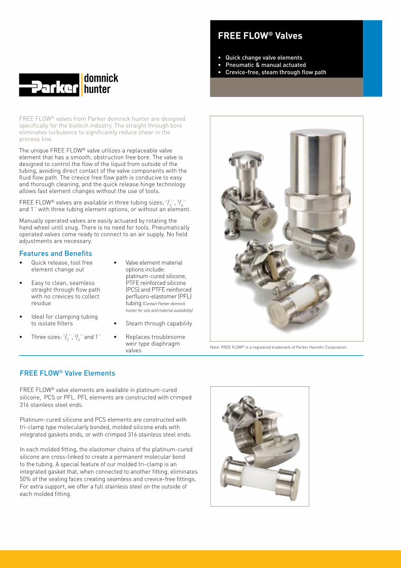
FREE FLOW® valves from Parker domnick hunter are designed specifically for the biotech industry. The straight through bore eliminates turbulence to significantly reduce shear in the process line.
The unique FREE FLOW® valve utilizes a replaceable valve element that has a smooth, obstruction free bore. The valve is designed to control the flow of the liquid from outside of the tubing, avoiding direct contact of the valve components with the fluid flow path. The crevice free flow path is conducive to easy and thorough cleaning, and the quick release hinge technology allows fast element changes without the use of tools.
FREE FLOW® valves are available in three tubing sizes; 1/2¨, 3/4¨ and 1¨ with three tubing element options, or without an element.
Manually operated valves are easily actuated by rotating the hand wheel until snug. There is no need for tools. Pneumatically operated valves come ready to connect to an air supply. No field adjustments are necessary.
Features and Benefits• Quick release, tool free
element change out
• Easy to clean, seamless straight through flow path with no crevices to collect residue
• Ideal for clamping tubing to isolate filters
• Three sizes: 1/2¨, 3/4¨ and 1¨
• Valve element material options include: platinum-cured silicone, PTFE reinforced silicone (PCS) and PTFE reinforced perfluoro-elastomer (PFL) tubing (Contact Parker domnick
hunter for size and material availability)
• Steam through capability
• Replaces troublesome weir type diaphragm valves
FREE FLOW® Valves
• Quick change valve elements• Pneumatic & manual actuated• Crevice-free, steam through flow path
FREE FLOW® Valve Elements
FREE FLOW® valve elements are available in platinum-cured silicone, PCS or PFL. PFL elements are constructed with crimped 316 stainless steel ends.
Platinum-cured silicone and PCS elements are constructed with tri-clamp type molecularly bonded, molded silicone ends with integrated gaskets ends, or with crimped 316 stainless steel ends.
In each molded fitting, the elastomer chains of the platinum-cured silicone are cross-linked to create a permanent molecular bond to the tubing. A special feature of our molded tri-clamp is an integrated gasket that, when connected to another fitting, eliminates 50% of the sealing faces creating seamless and crevice-free fittings. For extra support, we offer a full stainless steel on the outside of each molded fitting.
Note: FREE FLOW® is a registered trademark of Parker Hannifin Corporation.
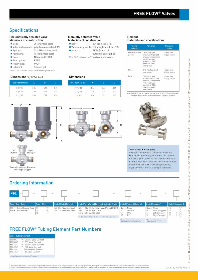
BC
SpecificationsPneumatically actuated valveMaterials of construction Body: 304 stainless steel Valve sealing anvils: polyphenylene sulfide (PPS) Springs: 17-4PH stainless steel Fasteners: 18-8 stainless steel Seals: Nitrile and EPDM Stem guides: PEEK Piston stop: PVDF Lubricant: Silicone gelNote: 316L stainless steel is available by special order.
Dimensions (1/8¨ NPT air inlet)
Ordering Information
FREE FLOW® Valves
Tube element size A B C
1/2¨(3/8¨ID) 3.36 5.18 5.76
3/4¨(5/8¨ID) 3.90 5.80 6.45
1¨(7/8¨ID) 4.40 7.94 8.63
Manually actuated valve Materials of construction Body: 304 stainless steel Valve sealing anvils: polyphenylene sulfide (PPS) Inserts: PEEK (standard, autoclave compatible)Note: 316L stainless steel is available by special order.
Dimensions
Tube element size A B C
1/2¨(3/8¨ID) 3.36 3.23 3.81
3/4¨(5/8¨ID) 3.90 4.07 4.72
1¨(7/8¨ID) 4.40 5.54 6.23
A
BC
A
Elementmaterials and specifications
Tubing Port ends Pressure material rating
Platinum-cured silicone
Tri-clamp type, molecularly bonded, molded silicone ends with integrated gaskets or 316L stainless steel crimp ends
45 psig line, 30 psig steam
PFL 316 stainless steel crimp ends
60 psig line, 40 psig steam
PCS Tri-clamp type, molecularly bonded, molded silicone ends with integrated gaskets or 316L stainless steel crimp ends
60 psig line, 40 psig steam
Note: Elements can be cleaned and sterilized by SIP / CIP and autoclave. Element materials are animal free and USP class VI approved
FFL -
Code ǀ Body Type
QR Quick Release BodyBlank Bolted Body
Code ǀ Body Material
SS 304 Stainless SteelS6 316 Stainless Steel
Code ǀ Top Works Material & Actuator Style
SAM 304 SS, Autoclaveable, Manual (PEEK)SSFC 304 SS, Fail CloseSSFO 304 SS, Fail Open
Code ǀ Snugger*
Blank NoneB Both SnuggersL Left SnuggerR Right Snugger
Code ǀ Snugger ID
10 5/8¨14 7/8¨20 1 - 1/4¨22 1 - 3/8¨
---
* Only used with continuous tubing elements
-
Code ǀ Element Material
Blank NoneSI SiliconeSP PCSCS PFL
* Contact Parker domnick hunter for material availability in specific sizes
-
Certification & PackagingEach valve element is shipped in sealed bag with a label denoting part number, lot number and description. A certificate of conformance is included with each shipment to certify that each element passes USP Class VI, cytotoxicity, physiochemical and visual inspection tests.
Code ǀ Size
08 1/2¨12 3/4¨16 1¨
-
* Contact Parker domnick hunter for high and low pressure options.
DS_P_30_01/13 Rev. 1AParker domnick hunter has a continuous policy of product development and although the Company reserves the right to change specifications, it attempts to keep customers informed of any alterations. This publication is for general information only and customers are requested to contact our Process Filtration Sales Department for detailed information and advice on a products suitability for specific applications. All products are sold subject to the company’s Standard conditions of sale.
LeftSnugger
RightSnugger
Valve orientation to determine left & right snugger
FREE FLOW® Tubing Element Part NumbersCode ǀ Tubing Element
FFL08SI 1/2¨ Silicone Valve ElementFFL08SP 1/2¨ PCS Valve ElementFFL12SI 3/4¨ Silicone Valve ElementFFL12SP 3/4¨ PCS Valve ElementFFL16SI 1¨ Silicone Valve ElementFFL16SP 1¨ PCS Valve Element
* Contact Parker domnick hunter for PFL options.
Euro
pe:
+44
(0)1
91 4
1051
21
dhp
roce
ss@
park
er.c
om -
Nor
th A
mer
ica:
✆ to
ll fr
ee 8
77 7
84 2
234
✆ +
1 80
5 60
4 34
00
dhp
sale
s.na
@pa
rker
.com
w
ww.
park
er.c
om/d
hsin
gleu
se

FREE FLOW® sampling valves from Parker domnick hunter have a standard three port configuration consisting of manually actuated parent and child valves in a stainless steel housing.
The smooth bored tubing element is molded into a seamless T shape to convey fluid through the three ports. Valve sealing anvils along with compression bars control the flow from outside the tubing, never having contact with the media. Quick release hinge technology allows fast element changes without the use of tools.
Each port has a molded tri-clamp end with an integrated gasket to reduce sealing faces and potential contamination. Custom continuous tubing elements are also available.
Manually operated valves are easily actuated by rotating the hand wheel until snug. There is no need for tools. Pneumatically operated valves come ready to connect to an air supply. No field adjustments are necessary.
Features and Benefits
• Quick release, tool free element change out
• Easy to clean, seamless straight through flow path
• Ideal for large volume sampling, additions, and block and bleed applications
• Valve element material is platinum cured silicone
• Completely drainable in any position
• Steam through capability
FREE FLOW® Sampling Valves
• Manually actuated parent and child valves• Multiple ports with smooth flow paths
and steam through capability
Note: FREE FLOW® is a registered trademark of Parker Hannifin Corporation.
FREE FLOW® Sampling Valve Tubing Elements
The tube element material is molded into a T configuration providing a seamless fluid path with no areas of entrapment. Custom elements can be molded with a continuous leg for connection to tubing and bag systems.
Parker domnick hunter’s FREE FLOW® sampling valves feature quick release hinge technology for fast element changes. It is as simple as loosening the locking screws, unhinging the valve bodies, and removing the tubing element. Then all product contact surfaces can be disposed without the need for cleaning or sanitizing the stainless steel parts.

SpecificationsFREE FLOW® sampling valvesMaterials of construction Tube element: USP Class VI platinum cured silicone tubing (animal free) Body: Metal components are 304 stainless steel* Valve sealing anvils: polyphenylene sulfide (PPS)Note: 316L stainless steel is available by special order.
Dimensions
Ordering Information
FREE FLOW® Sampling Valves
Tube element size
1/2¨(3/8¨ID)
Elementmaterials and specifications
Tubing Port ends Pressure material rating
Platinum-cured silicone
Tri-clamp type, molecularly bonded, molded silicone ends with integrated gaskets
45 psig line, 30 psig steam
Note: Elements can be cleaned and sterilized by SIP / CIP and autoclave. Elements materials are animal free and USP class VI approved.
FFLQR2P -
Code ǀ Size
08 1/2¨
Code ǀ Body Material
SS 304 Stainless SteelS6 316 Stainless Steel
Code ǀ Top Works Material & Actuator Style
SAM 304 SS, Autoclaveable, Manual (PEEK)
--
Code ǀ Element Material
Blank NoneSI Silicone
2.98
10◦
1.34
2.82
3.63
Tubing Element
Certification & PackagingEach valve element is shipped in sealed bag with a label denoting part number, lot number and description. A certificate of conformance is included with each shipment to certify that each element passes USP Class VI, cytotoxicity, physiochemical and visual inspection tests.
-
Code ǀ Child Valve
Blank None CL Child Valve
DS_P_31_02/14 Rev. 1AParker domnick hunter has a continuous policy of product development and although the Company reserves the right to change specifications, it attempts to keep customers informed of any alterations. This publication is for general information only and customers are requested to contact our Process Filtration Sales Department for detailed information and advice on a products suitability for specific applications. All products are sold subject to the company’s Standard conditions of sale.
FREE FLOW® Sampling Valve Element Part NumberCode ǀ Tubing Element
FFL2P08SI 1/2¨ Element Ported FREE FLOW® Valve
Euro
pe:
+44
(0)1
91 4
1051
21
dhp
roce
ss@
park
er.c
om -
Nor
th A
mer
ica:
✆ to
ll fr
ee 8
77 7
84 2
234
✆ +
1 80
5 60
4 34
00
dhp
sale
s.na
@pa
rker
.com
w
ww.
park
er.c
om/d
hsin
gleu
se

Process and analytical filter discs from Parker domnick hunter are available in a range of pore size and a choice of five materials.
Membrane discs:• Cellulose mixed esters• Polyethersulphone• Nylon
Fibrous media discs:• Glass microfibre• Polypropylene
The discs are supplied interleaved between two protecting layers with the feed surface oriented upwards in the box.
Features and Benefits
• High throughput rates
• Superior flow characteristics
• Easy to handle
• Reduced filtration time
• Low protein binding
Filter Discs
• liquid filters• various membrane / media
Standard diameters 047 mm.Diameters 025mm, 090 mm & 142 mm
are also available.For full ordering information, variants,
quantities and availability,please contact Parker domnick hunter.
Parker domnick hunter has a continuous policy of product development and although the Company reserves the right to change specifications, it attempts to keep customers informed of any alterations. This publication is for general information only and customers are requested to contact our Process Filtration Sales Department for detailed information and advice on a products suitability for specific applications. All products are sold subject to the company’s Standard conditions of sale.
Euro
pe:
+44
(0)1
91 4
1051
21
dhp
roce
ss@
park
er.c
om -
Nor
th A
mer
ica:
✆ +
1 60
8 82
4 05
00
dhp
sale
s.na
@pa
rker
.com
w
ww.
park
er.c
om/d
hpha
rma
DS_P_33_07/13 Rev. 1A
Product Code | Micron Code ǀ Quantity
Biopharmaceutical Filters
Code ǀ Product
PDGF PROCLEAR GFPDGP PROCLEAR GPPDPP PROCLEAR PPZDBR PROPOR BRZDHC PROPOR HCZDMR PROPOR MRZDSG PROPOR SG
Code ǀ Diameter
047 ø47 Y 50 Y 50 Y 50 Y 50 Y 50 Y 50
PROCLEAR GF 96 0.6 µm 01 1.0 µm 02 2.0 µm 05 5.0 µm 07 7.0 µm 10 10.0 µm
Y 50 Y 50
PROCLEAR GP 95 0.5 µm 96 0.6 µm
Y 50PROPOR MR 610 0.1 µm
Z 100 Z 100 Z 100
PROPOR SG 010 0.10 µm 020 0.20 µm 045 0.45 µm
Y 50 Y 50 Y 50 Y 50 Y 50 Y 50 Y 50 Y 50 Y 50 Y 50 Y 50 Y 50 Y 50
PROCLEAR PP 96 0.6 µm 01 1.0 µm 03 3.0 µm 05 5.0 µm 07 7.0 µm 10 10.0 µm 15 15.0 µm 20 20.0 µm 25 25.0 µm 40 40.0 µm 55 55.0 µm 75 75.0 µm 100 100.0 µm
Y 50PROPOR BR 020 0.20 µm
Y 50PROPOR HC 620 0.20 µm

HIGH FLOW PREPOR GFA is a high capacity glass fibre prefilter specifically designed for the removal of bulk particulate from compressed air and gases.
It is used extensively for prefiltration duties in dry compressed air systems and provides excellent protection for final sterile filters.
HIGH FLOW PREPOR GFA utilizes pleated glass fibre filter media encased within an upstream and downstream expanded polypropylene mesh filter support. The pleat pack is supported by an inner stainless steel core and outer heat stabilized polypropylene cage, heat bonded to heat stabilized polypropylene end caps.
The combination of high voids volume filter media andpleated construction results in a filter cartridge with exceptional dirt holding capacity, able to operate at very low differential pressures.
Features and Benefits
Cartridge flow rates20¨ Size (500 mm)
• High surface area and voids volume filter media
• Exceptionally high flow rates with low pressure drops
• Reliable efficient protection of final sterilization filters
• Heat stabilized componentry to allow operation at elevated temperatures
Performance Characteristics
HIGH FLOW PREPOR GFAFilters• air / gas filters• glass microfibre
Note: PREPOR is a registered trademark of Parker Hannifin Corporation.
200
180
160
140
120
100
80
60
40
20
0
Diff
eren
tial
Pre
ssur
e (m
bar) 2.5
2.0
1.5
1.5
0.5
0
Diff
eren
tial
Pre
ssur
e (p
si)
0 100 200 300 400 500 600 700
Flow (Nm3 / hr) (air @ 21 °C)
Cartridge flow rates10¨ Size (250 mm)
400
350
300
250
200
150
100
50
0
Diff
eren
tial
Pre
ssur
e (m
bar) 5
4
3
2
1
0
Diff
eren
tial
Pre
ssur
e (p
si)
0 100 200 300 400 500 600 700
Flow (Nm3 / hr) (air @ 21 °C)
2 barg
0 barg 0 barg
2 barg

SpecificationsMaterials of Construction Filtration Media: Glass Microfibre Upstream Support: Polypropylene Downstream Support: Polypropylene Inner Support Core: 316L Stainless Steel Outer Protection Cage: Polypropylene End Caps: Polypropylene End Cap Insert: Stainless Steel Standard o-rings/gaskets: Silicone
Biological SafetyMaterials conform to the relevant requirements of 21CFR Part 177, EC1935 / 2004 and current USP Plastics Class VI - 121 °C and ISO10993 equivalents.
Recommended Operating ConditionsThe maximum differential pressure in direction of flow (outside to in) is 3.5 barg (50.76 psig) at 20 °C (68 °F). The maximum recommended continuous operating temperature is 70 °C (158 °F).Note: For temperatures from 70 °C (158 °F) to 100 °C (212 °F)
a special product with polyester supports is available.
Effective Filtration Area (EFA)10¨ (250 mm) 0.48 m2 (5.16 ft2)
Ordering Information
ZCHP - -
Code ǀ Length (Nominal)
1 10¨ (250 mm)2 20¨ (500 mm)3 30¨ (750 mm)
Code ǀ Micron
1.0 1.0 µm
Code ǀ Endcap (10¨)
C BF / 226 BayonetP BIO-X Retrofit
Code ǀ O-rings
E EPDMS SiliconeV Viton
HIGH FLOW PREPOR GFA Filters
Code ǀ Variant*
S4* High Temperature
* Only available with Silicone o-rings.
Parker domnick hunter has a continuous policy of product development and although the Company reserves the right to change specifications, it attempts to keep customers informed of any alterations. This publication is for general information only and customers are requested to contact our Process Filtration Sales Department for detailed information and advice on a products suitability for specific applications. All products are sold subject to the company’s Standard conditions of sale.
Euro
pe:
+44
(0)1
91 4
1051
21
dhp
roce
ss@
park
er.c
om -
Nor
th A
mer
ica:
✆ +
1 60
8 82
4 05
00
dhp
sale
s.na
@pa
rker
.com
w
ww.
park
er.c
om/d
hpha
rma
DS_P_34_07/13 Rev. 1A

PEPLYN AIR filter cartridges have been specifically designed to guarantee removal of particulate from gas streams.
They can be used to protect sterilizing grade filters in pressurized systems or in exhaust gas vent applications.
PEPLYN AIR is particularly suitable for:
• Inlet gas in the fermentation industry as protection to sterilizing grade filters where polypropylene media is preferred
• As protection to sterilizing grade filters in exhaust gas systems
• Vent applications
• Systems where high particulate loading is expected
PEPLYN AIR has the ability to be steam sterilized and has a broad range of chemical compatibility
Features and Benefits
Cartridge flow rates @ 0 barg10¨ Size (250 mm)
• Cost-effective prefiltration
• Absolute micron rating range from 1.0 - 25 micron
• High flow rates and long life
• Steam sterilizable
• Graded density for excellent particle retention
• No release of particles even during system pressure fluctuations
Performance Characteristics
PEPLYN AIR Filters
• air / gas filters• meltblown polypropylene
Note: PEPLYN is a registered trademark of Parker Hannifin Corporation.
600
500
400
300
200
100
0
Diff
eren
tial
Pre
ssur
e (m
bar)
8
7
6
5
4
3
2
1
0
Diff
eren
tial
Pre
ssur
e (p
si)
0 100 200 300 400 500 600 700
Flow (Nm3 / hr)
Flow rates for other sizes available upon request
Cartridge flow rates @ 2 barg10¨ Size (250 mm)
250
200
150
100
50
0
Diff
eren
tial
Pre
ssur
e (m
bar)
3
2
1
0
Diff
eren
tial
Pre
ssur
e (p
si)
Flow rates for other sizes available upon request
1 µm
0 100 200 300 400 500 600 700
Flow (Nm3 / hr)
10 µm
25 µm
5 µm
1 µm
25 µm
10 µm
5 µm

SpecificationsMaterials of Construction Filtration Media: Meltblown Polypropylene Upstream Support: Polypropylene Downstream Support: Polypropylene Inner Support Core: 316L Stainless Steel Outer Protection Cage: Polypropylene End Caps: Polypropylene Standard o-rings/gaskets: Silicone
Biological SafetyMaterials conform to the relevant requirements of 21CFR Part 177 and current USP Plastics Class VI - 121 °C and ISO10993 equivalents.
Recommended Operating ConditionsThe maximum differential pressure in direction of flow (outside to in) is 3.5 barg (50.76 psig) at 20 °C (68 °F).
The maximum recommended continuous operating temperature is 50 °C (122 °F).
Effective Filtration Area (EFA)*10¨ (250 mm) 0.49 m2 (5.27 ft2)*Varies with micron rating
Cleaning and SterilizationPEPLYN AIR cartridges can be repeatedly in situ steam sterilized or autoclaved up to142 °C (287.6 °F). Determination of Micron RatingsParticle removal efficiencies of PEPLYN AIR cartridges have been determined independently by challenging with a cut silica test dust, generated by BUS1701 dust injector used in conjunction with laser particle counters.
Micron Efficiency Ratings
Ordering Information
ZCPH - -
Code ǀ Length (Nominal)
B* 2.5¨ (65 mm)A* 5¨ (125 mm)K 5¨ (125 mm)1 10¨ (250 mm)2 20¨ (500 mm)3 30¨ (750 mm)
Code ǀ Micron
1.0 1.0 µm005 5.0 µm010 10.0 µm025 25.0 µm
Code ǀ Endcap (10¨)
C BF / 226 BayonetH UF Retrofit
Code ǀ O-rings
E EPDMP PTFE Encapsulated SiliconeS* SiliconeV Viton
PEPLYN AIR Filters
120
100
80
60
40
20
0
Ret
enti
on E
ffici
ency
0 2 4 6 8 10
Particle Diameter
1 µm
120
100
80
60
40
20
0R
eten
tion
Effi
cien
cy0 5 10 15 20 25 30 35 40 45
Particle Diameter
5 µm
10 µm 25 µm
Code ǀ Endcap (Demi)
T TRUESEALY Demi StubZ Demi A & B Std
DS_P_35_07/13 Rev. 1A
* Supplied in Packs of 3.
* Silicone o-ring supplied as standard without having to specify the ‘S’ code.
Parker domnick hunter has a continuous policy of product development and although the Company reserves the right to change specifications, it attempts to keep customers informed of any alterations. This publication is for general information only and customers are requested to contact our Process Filtration Sales Department for detailed information and advice on a products suitability for specific applications. All products are sold subject to the company’s Standard conditions of sale.
Euro
pe:
+44
(0)1
91 4
1051
21
dhp
roce
ss@
park
er.c
om -
Nor
th A
mer
ica:
✆ +
1 60
8 82
4 05
00
dhp
sale
s.na
@pa
rker
.com
w
ww.
park
er.c
om/d
hpha
rma

HIGH FLOW BIO-X combines proven depth filter technology and a pleated construction to provide retention down to 0.01 micron in gas.
Flow rates typically 2-3 times that of membrane filters make HIGH FLOW BIO-X the filter that can dramatically reduce cartridge usage and installation size within the fermentation, food and beverage industries.
The specially developed PTFE impregnation process imparts greater strength and permanent hydrophobicity to the borosilicate microfibre media. This leads to excellent performance in applications such as the provision of sterile gas in filling machines.
Features and Benefits
10¨ Size (250 mm) Cartridge
• 94% voids volume PTFE impregnated microfibre
• Wide bore cartridge construction to maximize flow rate
• Stainless steel inner core
• Exceptionally high flow rates with low pressure drops
• Fully validated by aerosolized bacterial and viral challenge
Performance Characteristics
HIGH FLOW BIO-X Filters• air / gas filters• PTFE impregnated borosilicate microfibre
Note: BIO-X is a registered trademark of Parker Hannifin Corporation.
600
500
400
300
200
100
0
Diff
eren
tial
Pre
ssur
e (m
bar)
8
7
6
5
4
3
2
1
0
Diff
eren
tial
Pre
ssur
e (p
si)
0 100 200 300 400 500 600 700
Flow (Nm3 / hr) (air @ 21 °C)
Flow rates for other sizes available upon request
A Size (125 mm) Cartridge
200
150
100
50
0
Diff
eren
tial
Pre
ssur
e (m
bar)
1.5
1.0
0.5
0
Diff
eren
tial
Pre
ssur
e (p
si)
0 10 20 30 40 50 60 70 80 90
Flow (Nm3 / hr) (air @ 21 °C)
Flow rates for other sizes available upon request
0 barg
2 barg
0 barg
2 barg

SpecificationsMaterials of Construction Filtration Media: PTFE Impregnated Borosilicate Microfibre Upstream Support: Polypropylene Downstream Support: Polypropylene Inner Support Core: 316L Stainless Steel Outer Protection Cage: Polypropylene End Caps: Polypropylene End Cap Insert: 316L Stainless Steel Standard o-rings/gaskets: Silicone
Biological SafetyMaterials conform to the relevant requirements of 21CFR Part 177, EC1935 / 2004 and current USP Plastics Class VI - 121 °C and ISO10993 equivalents.
Recommended Operating ConditionsThe maximum differential pressure in direction of flow (outside to in) is 3.5 barg (50.76 psig) at 70 °C (158 °F).
The maximum recommended continuous operating temperature is 70 °C (158 °F).
Effective Filtration Area (EFA)10¨ (250 mm) 0.38 m2 (4.09 ft2) SterilizationHIGH FLOW BIO-X cartridges can be in situ steam sterilized or autoclaved up to 142 °C (287.6 °F) for a maximum of 150 steam cycles.
Retention CharacteristicsThe HIGH FLOW BIO-X range of cartridges has been fully validated by aerosol bacterial challenge levels of 1012 Brevundimonas diminuta per 10¨ (250 mm) filter cartridge. Independent test work also shows full retention to MS-2 Coliphage.
Integrity Test DataAll cartridges are integrity tested prior to despatch by the aerosol challenge test method using the Parker domnick hunter VALAIRDATA II.
Ordering Information
ZCHB -
Code ǀ Length (Nominal)
B* 2.5¨ (65 mm)A* 5¨ (125 mm)K 5¨ (125 mm)1 10¨ (250 mm)2 20¨ (500 mm)3 30¨ (750 mm)
Code ǀ Endcap (10¨)
C P-7P BIO-X RetrofitH UF Retrofit
HIGH FLOW BIO-X Filters
Code ǀ Endcap (Demi)
H UF RetrofitT TRUESEALY Demi MCYZ Demi A & B Std
DS_P_36_07/13 Rev. 1A
* Supplied in packs of 3.
Code ǀ O-rings
E EPDMS* SiliconeV Viton
* Silicone o-ring supplied as standard without having to specify the ‘S’ code.
-
Parker domnick hunter has a continuous policy of product development and although the Company reserves the right to change specifications, it attempts to keep customers informed of any alterations. This publication is for general information only and customers are requested to contact our Process Filtration Sales Department for detailed information and advice on a products suitability for specific applications. All products are sold subject to the company’s Standard conditions of sale.
Euro
pe:
+44
(0)1
91 4
1051
21
dhp
roce
ss@
park
er.c
om -
Nor
th A
mer
ica:
✆ +
1 60
8 82
4 05
00
dhp
sale
s.na
@pa
rker
.com
w
ww.
park
er.c
om/d
hpha
rma
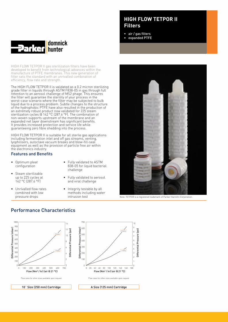
HIGH FLOW TETPOR II gas sterilization filters have been developed to benefit from technological advances within the manufacture of PTFE membranes. This new generation of filter sets the standard with an unrivalled combination of efficiency, flow rate and strength.
The HIGH FLOW TETPOR II is validated as a 0.2 micron sterilizing grade filter in liquids through ASTM F838-05 in gas through full retention to an aerosol challenge of MS2 phage. This ensures the filter will guarantee the sterility of your process in the worst-case scenario where the filter may be subjected to bulk liquid due to a process problem. Subtle changes to the structure of the hydrophobic PTFE have also resulted in the production of an extremely robust product now validated for 225 steam sterilization cycles @ 142 °C (287.6 °F). The combination of non-woven supports upstream of the membrane and an expanded net layer downstream has significant benefits. It provides increased protection and service life while guaranteeing zero fibre shedding into the process.
HIGH FLOW TETPOR II is suitable for all sterile gas applications including fermentation inlet and off gas streams, venting, lyophilisers, autoclave vacuum breaks and blow-fill-seal equipment as well as the provision of particle free air within the electronics industry.
Features and Benefits
10¨ Size (250 mm) Cartridge
• Optimum pleat configuration
• Steam sterilizable up to 225 cycles at 142 °C (287.6 °F)
• Unrivalled flow rates combined with low pressure drops
• Fully validated to ASTM 838-05 for liquid bacterial challenge
• Fully validated to aerosol and viral challenge
• Integrity testable by all methods including water intrusion test
Performance Characteristics
HIGH FLOW TETPOR IIFilters• air / gas filters• expanded PTFE
Note: TETPOR is a registered trademark of Parker Hannifin Corporation.
1000
900
800
700
600
500
400
300
200
100
0
Diff
eren
tial
Pre
ssur
e (m
bar)
14
12
10
8
6
4
2
0
Diff
eren
tial
Pre
ssur
e (p
si)
0 100 200 300 400 500 600 700
Flow (Nm3 / hr) (air @ 21 °C)
Flow rates for other sizes available upon request
A Size (125 mm) Cartridge
700
600
500
400
300
200
100
0
Diff
eren
tial
Pre
ssur
e (m
bar)
10
9
8
7
6
5
4
3
2
1
0
Diff
eren
tial
Pre
ssur
e (p
si)
0 20 40 60 80 100 120 140 160 180
Flow (Nm3 / hr) (air @ 21 °C)
Flow rates for other sizes available upon request
2 barg
0 barg
0 barg
2 barg

SpecificationsMaterials of Construction Filtration Membrane: Expanded PTFE Upstream Support: Polypropylene Downstream Support: Polypropylene Inner Support Core: 316L Stainless Steel Outer Protection Cage: Polypropylene End Caps: Polypropylene End Cap Insert: Polysulphone Standard o-rings: Silicone
Biological SafetyMaterials conform to the relevant requirements of 21CFR Part 177, EC1935 / 2004 and current USP Plastics Class VI - 121 °C and ISO10993 equivalents.
Recommended Operating ConditionsThe maximum differential pressure in direction of flow (outside to in) is 3.5 barg (50.76 psig) at 60 °C (140 °F).
The maximum recommended continuous inlet air temperature is 60 °C (140 °F).Note: HIGH FLOW TETPOR II cartridges can be used as WFI vents in heated housings if changed on a 4-6 monthly basis.
SterilizationHIGH FLOW TETPOR II cartridges can be in situ steam sterilized for up to 225 cycles at 142 °C (287.6 °F). Retention CharacteristicsHIGH FLOW TETPOR II cartridges have been fully validated as 0.2 micron sterilizing grade filter cartridges, for compressed air and gas applications. They exceed liquid bacterial challenge levels as recommended by ASTM+. In addition, HIGH FLOW TETPOR II is also validated by aerosol bacterial and MS-2 Coliphage challenge testing.+ASTM American Society for Testing and Materials
Integrity Test DataAll cartridges are integrity tested prior to despatch by the pressure decay and aerosol challenge test methods. Values are for cartridges wetted with 60 / 40 IPA / Water.
Ordering Information
ZHFT / -
Code ǀ Length (Nominal)
D* 1.5¨ (35 mm)C* 2.5¨ (65 mm)B* 2.5¨ (65 mm)A* 5¨ (125 mm)K 5¨ (125 mm)1 10¨ (250 mm)2 20¨ (500 mm)3 30¨ (750 mm)
Code ǀ Endcap (10¨)
C P-7P BIO-X RetrofitH UF Retrofit
Code ǀ O-rings
E EPDMP+ PTFE Encapsulated SiliconeS* SiliconeV Viton
HIGH FLOW TETPOR II Filters
Cartridge Test Diffusional Water Water Water Pressure Flow Intrusion Intrusion Flow Test Pressure (bar) (psi) (ml / min) (barg) (psig) (ml / 10 min) (µl / 10 min)
D 0.8 11.6 0.6 2.5 36.2 N / A N / A
C 0.8 11.6 1.1 2.5 36.2 N / A N / A
B 0.8 11.6 2.8 2.5 36.2 2.3 657
A 0.8 11.6 5.6 2.5 36.2 4.6 1314
K 0.8 11.6 7.70 2.5 36.2 6.4 1828
10¨ 0.8 11.6 16.50 2.5 36.2 13.5 3857
20¨ 0.8 11.6 33.00 2.5 36.2 27.0 7714
30¨ 0.8 11.6 49.50 2.5 36.2 40.5 11571
Code ǀ Endcap (Demi)
H UF RetrofitT TRUESEALW HF Demi C & DY Demi MCYZ Demi A & B Std
DS_P_37_07/13 Rev. 1A
* Supplied in packs of 3.
+ Not available on C and D length variants.* Silicone o-ring supplied as standard without having to specify the ‘S’ code.
Parker domnick hunter has a continuous policy of product development and although the Company reserves the right to change specifications, it attempts to keep customers informed of any alterations. This publication is for general information only and customers are requested to contact our Process Filtration Sales Department for detailed information and advice on a products suitability for specific applications. All products are sold subject to the company’s Standard conditions of sale.
Euro
pe:
+44
(0)1
91 4
1051
21
dhp
roce
ss@
park
er.c
om -
Nor
th A
mer
ica:
✆ +
1 60
8 82
4 05
00
dhp
sale
s.na
@pa
rker
.com
w
ww.
park
er.c
om/d
hpha
rma

HIGH FLOW TETPOR H.T. gas sterilization filter cartridges provide unrivalled performance in process industry applications where continuous cartridge operation of up to 100 °C (212 °F) is a requirement.
Applications include specific biological fermentations whichuse high inlet air temperatures and heated vent filters on storage tanks whose contents are at elevated temperatures >80 °C (176 °F), e.g. WFI tanks.
HIGH FLOW TETPOR H.T. cartridges utilize a proven inherently hydrophobic, expanded PTFE membrane validated as sterilizing grade in liquid in accordance with ASTM F838-05. This ensures the removal of all airborne bacteria, viruses and bacteriophage. Polyaramid membrane support layers facilitate continuous operation at temperatures up to 100 °C (212 °F).
Features and Benefits
10¨ Size (250 mm) Cartridge
• Long service life even at elevated temperatures 100 °C (212 °F)
• Assured biosecurity with absolute rated filtration
• Stainless steel inner core
• Steam sterilizable to 142 °C (287 °F)
• Exceptionally high flow rates with low pressure drops
Performance Characteristics
HF TETPOR H.T. Filters
• air / gas filters• expanded PTFE
Note: TETPOR is a registered trademark of Parker Hannifin Corporation.
800
700
600
500
400
300
200
100
0
Diff
eren
tial
Pre
ssur
e (m
bar)
11
10
9
8
7
6
5
4
3
2
1
0
Diff
eren
tial
Pre
ssur
e (p
si)
0 100 200 300 400 500 600
Flow (Nm3 / hr) @ 21 °C
0 barg
2 barg
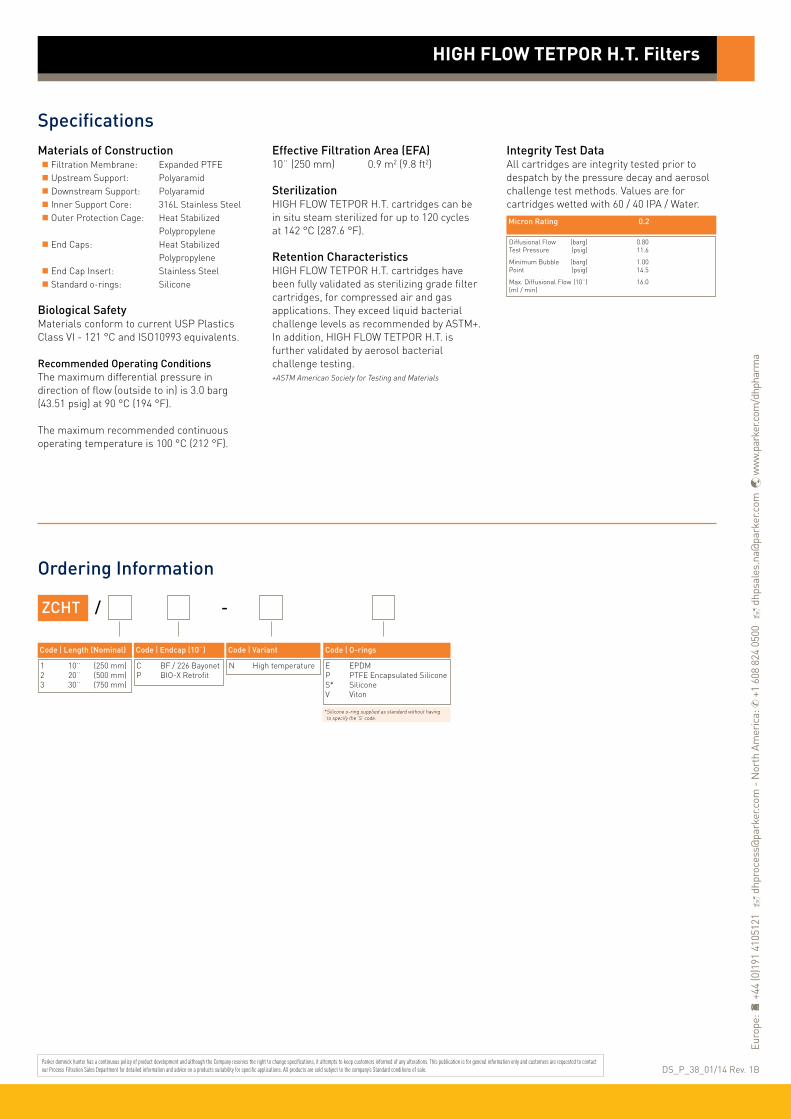
SpecificationsMaterials of Construction Filtration Membrane: Expanded PTFE Upstream Support: Polyaramid Downstream Support: Polyaramid Inner Support Core: 316L Stainless Steel Outer Protection Cage: Heat Stabilized Polypropylene End Caps: Heat Stabilized Polypropylene End Cap Insert: Stainless Steel Standard o-rings: Silicone
Biological SafetyMaterials conform to current USP Plastics Class VI - 121 °C and ISO10993 equivalents.
Recommended Operating ConditionsThe maximum differential pressure in direction of flow (outside to in) is 3.0 barg (43.51 psig) at 90 °C (194 °F).
The maximum recommended continuous operating temperature is 100 °C (212 °F).
Effective Filtration Area (EFA)10¨ (250 mm) 0.9 m2 (9.8 ft2)
SterilizationHIGH FLOW TETPOR H.T. cartridges can be in situ steam sterilized for up to 120 cycles at 142 °C (287.6 °F).
Retention CharacteristicsHIGH FLOW TETPOR H.T. cartridges have been fully validated as sterilizing grade filter cartridges, for compressed air and gas applications. They exceed liquid bacterial challenge levels as recommended by ASTM+.In addition, HIGH FLOW TETPOR H.T. is further validated by aerosol bacterial challenge testing.+ASTM American Society for Testing and Materials
Integrity Test DataAll cartridges are integrity tested prior to despatch by the pressure decay and aerosol challenge test methods. Values are for cartridges wetted with 60 / 40 IPA / Water.
Ordering Information
ZCHT / -
Code ǀ Length (Nominal)
1 10¨ (250 mm)2 20¨ (500 mm)3 30¨ (750 mm)
Code ǀ Endcap (10¨)
C BF / 226 BayonetP BIO-X Retrofit
Code ǀ Variant
N High temperature
Code ǀ O-rings
E EPDMP PTFE Encapsulated SiliconeS* SiliconeV Viton
HIGH FLOW TETPOR H.T. Filters
Micron Rating 0.2
Diffusional Flow (barg) 0.80Test Pressure (psig) 11.6
Minimum Bubble (barg) 1.00Point (psig) 14.5
Max. Diffusional Flow (10¨) 16.0(ml / min)
DS_P_38_01/14 Rev. 1B
* Silicone o-ring supplied as standard without having to specify the ‘S’ code.
Parker domnick hunter has a continuous policy of product development and although the Company reserves the right to change specifications, it attempts to keep customers informed of any alterations. This publication is for general information only and customers are requested to contact our Process Filtration Sales Department for detailed information and advice on a products suitability for specific applications. All products are sold subject to the company’s Standard conditions of sale.
Euro
pe:
+44
(0)1
91 4
1051
21
dhp
roce
ss@
park
er.c
om -
Nor
th A
mer
ica:
✆ +
1 60
8 82
4 05
00
dhp
sale
s.na
@pa
rker
.com
w
ww.
park
er.c
om/d
hpha
rma

TETPOR AIR sterilization filter cartridges offer exceptional filtration performance while providing the highest levels of biosecurity throughout the process industry.
Operating at ambient temperature conditions, TETPOR AIRfilter cartridges provide a cost-effective filtration solution. A unique polypropylene prefilter layer extends service life in heavily contaminated environments.
TETPOR AIR filter cartridges also utilize a well-proven, inherently hydrophobic expanded PTFE membrane validated as sterilizing grade in liquid in accordance with ASTM F838-05. This ensures the removal of all airborne bacteria, viruses and bacteriophage.
Features and Benefits
10¨ Size (250 mm) Cartridge
• Assured biosecurity with absolute rated filtration
• High flow rates with low pressure drops
• High voids volume PTFE membrane
• Steam sterilizable to 142 °C (287.6 °F)
• Unique prefilter layer
Performance Characteristics
TETPOR AIR Filters
• air / gas filters• expanded PTFE
Note: TETPOR is a registered trademark of Parker Hannifin Corporation.
900
800
700
600
500
400
300
200
100
0
Diff
eren
tial
Pre
ssur
e (m
bar)
12
11
10
9
8
7
6
5
4
3
2
1
0
Diff
eren
tial
Pre
ssur
e (p
si)
0 100 200 300 400 500 600 700
Flow (Nm3 / hr) (air @ 21 °C)
B Size (65 mm) Cartridge
1000
900
800
700
600
500
400
300
200
100
0
Diff
eren
tial
Pre
ssur
e (m
bar)
14
12
10
8
6
4
2
0
Diff
eren
tial
Pre
ssur
e (p
si)
0 20 40 60 80 100 120 140 160 180
Flow (Nm3 / hr) (air @ 21 °C)
0 barg 2 barg0 barg
2 barg

TETPOR AIR Filters
SpecificationsMaterials of Construction Filtration Membrane: Expanded PTFE Upstream Support: Polypropylene Downstream Support: Polypropylene
Filter Cartridges Inner Support Core: Polypropylene Outer Protection Cage: Polypropylene End Caps: Polypropylene End Caps Insert: 316L Stainless Steel Standard o-rings/gaskets: Silicone
MURUS Disposable Filter Capsules Core: Polypropylene Sleeve: Polypropylene Standard o-rings: Viton Capsule Body: Polypropylene Capsules Vent Seals: Silicone
DEMICAP Filter Capsules Core: Polypropylene Sleeve: Polypropylene End Caps: Polypropylene Capsule Body: Polypropylene Capsules Vent Seals: Silicone Filling Bell: Polycarbonate
Syringe Filters Body: Polypropylene
Recommended Operating ConditionsFilter CartridgesUp to 60 °C (140 °F) continuous operating temperature and higher short-term temperatures during CIP to the following limits:
MURUS Disposable Filter CapsulesUp to 25 °C ( 77 °F) @ 5.5 barg (79.7 psig)Up to 60 °C (140 °F) @ 2.8 barg (40.6 psig)
Parker Hannifin certify that this product complies with the European Council Pressure Equipment Directive (PED) 97/23/EC Article 3, Paragraph 3 - Sound Engineering Practice (SEP). This product is intended for use with Group 1 & 2 Dangerous and Harmless Liquids and Group 2 Harmless Gases at the operating conditions stated in this document : In compliance with PED Article 3, Paragraph 3, SEP, this product does not bear the CE mark.
DEMICAP Filter CapsulesUp to 40 °C (104 °F) at line pressures up to 5.0 barg (72 psig).
Effective Filtration Area (EFA)10¨ (250 mm): 0.77 m2 (8.28 ft2)K Size: 0.36 m2 (3.87 ft2)A Size: 0.25 m2 (2.69 ft2)B Size: 0.12 m2 (1.29 ft2)E Size: 0.06 m2 (0.64 ft2)Syringe ø50 mm: 14.50 cm2 (2.25 in2)
Sterilization
For detailed operational procedures and advice on cleaning and sterilization, please contact the Technical Support Group through your usual Parker domnick hunter contact. Biological SafetyMaterials conform to the relevant requirements of 21CFR Part 177 and current USP Plastics Class VI - 121 °C and ISO10993 equivalents.
Quality StandardsPharmaceutical grade products are manufactured in accordance with cGMP, 100% flushed with pharmaceutical grade purified water and integrity tested prior to despatch. A sample of each lot is tested to demonstrate conformity to validated claims.
Temperature Max. Forward dP °C °F (bar) (psi)
20 68 5.0 72.5
40 104 4.0 58.0
60 140 3.0 43.5
80 176 2.0 29.0
90 194 1.7 24.6
Autoclave Steam-in-Place Cycles Temp Cycles Temp (30 min.)
Cartridges 120 142 °C (287.6 °F) 120 142 °C (287.6 °F)
MURUS 5 130 °C (266 °F) - -
DEMICAP 100 135 °C (275 °F) - -
Syringe 1 130 °C (266 °F) - -

Performance CharacteristicsTOC / ConductivityThe filtrate quality from a 10¨ (250 mm) TETPOR AIR conforms to the requirements of current USP <643> (TOC) and USP <645> (conductivity).
EndotoxinsAqueous extracts from the 10¨ (250 mm) TETPOR AIR contain < 0.25 EU / ml when tested in accordance with the Limulus Amoebocyte Lysate test.
Non-Volatile Extractables (NVE)Total NVEs extracted in the first 5 litre flush of purified water for a 10¨ (250 mm)cartridge are <5 mg.
Pharmaceutical ValidationA full validation guide is available upon request from Laboratory Services Group (LSG).
Oxidizable SubstancesTETPOR AIR filter cartridges meet current USP and EP quality standards for sterile purified water for oxidizable substances following a <1 litre water flush.
Integrity Test DataAll filters are integrity testable to the following limits when wet with 60 / 40 : IPA /water and using air as the test gas.
Retention CharacteristicsTETPOR AIR filter cartridges are validated by bacterial challenge testing with Brevundimonas diminuta to current ASTM F838-05 methodology (107 organisms / cm2 EFA minimum) with typical in-house challenge levels being 1011 organisms per 10¨ (250 mm) filter cartridge.
TETPOR AIR Filters
Cartridge Test Diffusional Water Water Water Pressure Flow Intrusion Intrusion Flow Test Pressure (barg) (psig) (ml / min) (barg) (psig) (ml / 10 min) (µl / 10 min)
E 0.8 11.6 1.5 2.5 36.3 1.3 371
B 0.8 11.6 3.0 2.5 36.3 2.6 742
A 0.8 11.6 6.0 2.5 36.3 5.3 1514
K 0.8 11.6 8.3 2.5 36.3 7.2 2060
10¨ 0.8 11.6 17.7 2.5 36.3 15.3 4370

TETPOR AIR Filters
Ordering Information
ZLMT -
Code ǀ Length (Nominal)
K 5¨ (125 mm)1 10¨ (250 mm)2 20¨ (500 mm)3 30¨ (750 mm)
Code ǀ Micron
020 0.2 µm
Code ǀ Inlet Connection
A 3/4¨ Tri-ClampB 11/2¨ Tri-ClampD 1¨ HosebarbT 1¨ Tri-Clamp
Code ǀ Variant
A Air / Gas
MURUS Capsules
Code ǀ Outlet Connection
A 3/4¨ Tri-ClampB 11/2¨ Tri-ClampD 1¨ HosebarbT 1¨ Tri-Clamp
Code ǀ Grade
N Non-sterile
Code ǀ Design
L In-LineT* T-Port
Cartridges
DEMICAP Capsules
Code ǀ O-rings
E EPDMS* SiliconeV Viton
* Silicone o-ring supplied as standard without having to specify the ‘S’ code.
- -
Syringe Filters
ZCMT /
Code ǀ Length (Nominal)
B* 2.5¨ (65 mm)A* 5¨ (125 mm)K 5¨ (125 mm)1 10¨ (250 mm)2 20¨ (500 mm)3 30¨ (750 mm)
Code ǀ Micron
020 0.2 µm
Code ǀ Endcap (10¨)
B* dh DOEC BF / 226 BayonetD Fin / 222E Flat Top / 222F BF / 216/218G Recess / 222H UF RetrofitR BF / 222 Bayonet
Code ǀ O-rings
E EPDMP PTFE Encapsulated SiliconeS* SiliconeV Viton
Code ǀ Endcap (Demi)
SK RetrofitT TRUESEALX 116Y Demi StubZ Demi A & B Std
ZEMT -
Code ǀ Length (Nominal)
E 4.4¨ (113 mm)B 5.5¨ (140 mm)A 7.9¨ (200 mm)
Code ǀ Micron
020 0.2 µm
Code ǀ Inlet Connection
T 1¨ Tri-ClampN 1/2¨ NPT MaleH 1/2¨ HosebarbG Stepped HosebarbM 1/4¨ NPT MaleQ Walther QCR Grommel / QCV 3/8¨ NPT Female
Code ǀ Variant
A Air / Gas
Code ǀ Outlet Connection
T 1¨ Tri-ClampN 1/2¨ NPT MaleH 1/2¨ HosebarbG Stepped HosebarbM 1/4¨ NPT MaleQ Walther QCR Grommel / QCV 3/8¨ NPT Female
Code ǀ Pack N°
3 Pack of 3
-
Code ǀ Grade
N Non-Sterile
ZSMT -
Code ǀ Diameter
050 50 mm
Code ǀ Micron
020 0.2 µm
Code ǀ Inlet Connection
G Stepped HosebarbL 1/8¨ NPT Male
Code ǀ Variant
P Pharmaceutical
Code ǀ Grade
N Non-sterile
Code ǀ Options
S Standard
-
Code ǀ Pack N°
025 25 per box
-
DS_P_39_09/13 Rev. 1B
* Supplied in packs of 3.
Code ǀ Variant
A Air / Gas
* Silicone o-ring supplied as standard without having to specify the ‘S’ code.
* EPDM gaskets supplied as standard.
* Only available with a 1¨ Tri-Clamp.
Code ǀ Outlet Connection
G Stepped HosebarbL 1/8¨ NPT Male
Parker domnick hunter has a continuous policy of product development and although the Company reserves the right to change specifications, it attempts to keep customers informed of any alterations. This publication is for general information only and customers are requested to contact our Process Filtration Sales Department for detailed information and advice on a products suitability for specific applications. All products are sold subject to the company’s Standard conditions of sale.
Euro
pe:
+44
(0)1
91 4
1051
21
dhp
roce
ss@
park
er.c
om -
Nor
th A
mer
ica:
✆ +
1 60
8 82
4 05
00
dhp
sale
s.na
@pa
rker
.com
w
ww.
park
er.c
om/d
hpha
rma

Parker domnick hunter’s range of bag filters are manufactured from a variety of filter media each specifically chosen for its compatibility with a wide range of process liquids. Parker bag filters are of a fully welded design rather than sewn. No process liquid can bypass through needle holes caused by the sewing process or around a sewn ring. Parker domnick hunter’s range of filter bags include:
Standard filter bagsAvailable in polypropylene, polyester and nylon from 1 to 1000µm.
Extended life bagsIncreased thickness of the filter media can increase lifetime by up to 5 times that of a standard bag.
The filtration mechanism employed within filter bags allows high flow rates and high dirt holding capacity, this combined with low maintenance cost and quick change-out makes bag filtration an extremely cost effective means of liquid filtration. Bags are available to suit most common filter housings.
Features and Benefits
• From 1 to 1000 microns • Low maintenance costs and quick change-out
Performance Characteristics
Bag Filters
• mixed media, mesh and felt
Felt Media
25
20
15
10
5
0
Diff
eren
tial
Pre
ssur
e (m
bar)
0.4
0.3
0.2
0.1
0
Diff
eren
tial
Pre
ssur
e (p
sid)
0 50 100 150 200 250 300 350 400 450
Flow (L / min) for water @ 20 °C and 1 cp
For double length bags multiply flow rate by 2.1 For triple length by 3.2
1 µm
150 µm
5 µm
10 µm
50 µm
100 µm
Flow rate is dependant upon media type, micron rating and the fluid being filtered
Bag size Diameter Length Surface Area Volume Max Flow Rate
1 7¨ (180 mm) 17¨ (435 mm ) 0.25 m2 11.0 ltr 20 m3/hr
2 7¨ (180 mm) 32¨ (810 mm ) 0.5 m2 20.5 ltr 40 m3/hr
1 (mini) 4¨ (104 mm) 9¨ (230 mm ) 0.07 m2 1.9 ltr 6 m3/hr
2 (mini) 4¨ (180 mm) 15¨ (380 mm ) 0.12 m2 3.2 ltr 10 m3/hr

SpecificationsMaterials of Construction Filtration Media: Polypropylene Felt Viscose Felt Nylon Felt Polyester Felt Nomex* Felt Nylon Mesh Ring: Electro Plated Steel Stainless Steel Moulded Polypropylene Polypropylene Moulded Santoprene
*Nomex is a registered trademark of E.I. du Pont de Numours and Co Inc.
Viscous Flow Correction Factors
Compatibility
Ordering Information
Bag Filters
Code ǀ Ring
Code ǀ Ring
E Electro Plated SteelS Stainless SteelM Moulded PPP Polypropylene
E Electro Plated SteelS Stainless SteelM Moulded PPG Moulded P/EstQ Moulded Santoprene
Code ǀ Diameter
Code ǀ Diameter
7 Standard4 Mini
7 Standard4 Mini
Code ǀ Yarn
Code ǀ Yarn
Code ǀ Ring
Code ǀ Ring
Code ǀ Media
Code ǀ Media
1 Single2 Double3 Triple
1 Single2 Double3 Triple
H HandlesL Loops
X PlainL Loops
P Polypropylene Felt V Viscose FeltN Nylon FeltS Polyester FeltT Nomex FeltM Nylon Mesh
G PP Extra LifeF PE Extra Life
Code ǀ Felt Rating
Code ǀ Felt Rating
Code ǀ Mesh Rating
001 1*005 5 010 10025 25050 50100 100150 150
001 1*005 5 010 10025 25050 50100 100
045 45100 100150 150250 250 500 500800 800 999 1000
Bag Filters Standard
Extended Life Bag Filters
Code ǀ Style
Code ǀ Style
SG RingSC Band
SG Standard
*Not viscose
*Not viscose
Viscous Correction Factors
Material Max Organic Oils and Alkalies Organic Mineral Oxidising Resistance Temperature Solvents Fats Acids Acids Agents micro-organisms
Fluid Viscosity (cps) 10000 8000 6000 4000 2000 1500 1000 800 600 400 200 100 1
Flow rate (% water) 2.1 2.6 3.5 5 8 11 16 17 25 35 58 58 100
Polypropylene 95°C (203°F) Good V. Good Good V. Good Good Fair Fair
Viscose 121°C (250°F) V. Good V. Good Good Good Poor Fair Fair
Polyester 150°C (302°F) V. Good V. Good Good Good Good Good Good
Nylon 135°C (275°F) V. Good V. Good Good Fair Poor Poor Poor
Nomex 220°C (428°F) V. Good V. Good Good Fair Fair Poor Poor
Parker domnick hunter has a continuous policy of product development and although the Company reserves the right to change specifications, it attempts to keep customers informed of any alterations. This publication is for general information only and customers are requested to contact our Process Filtration Sales Department for detailed information and advice on a products suitability for specific applications. All products are sold subject to the company’s Standard conditions of sale.
Euro
pe:
+44
(0)1
91 4
1051
21
dhp
roce
ss@
park
er.c
om -
Nor
th A
mer
ica:
✆ +
1 60
8 82
4 05
00
dhp
sale
s.na
@pa
rker
.com
w
ww.
park
er.c
om/d
hpha
rma
DS_P_40_07/13 Rev. 1A

PEPLYN PLUS liquid filter cartridges are utilized for the clarification and prefiltration of a wide range of products in the fermentation and fine chemical industries.
The all polypropylene construction ensures a broad range of chemical compatibility making PEPLYN PLUS cartridges particularly suitable for the filtration of aggressive and viscous chemicals and solvents. They do not suffer from hydrolysis inaggressive solutions which would result in the contamination of the process fluid.
Extensive research has resulted in filter media with continuously graded fibre density giving progressively finer particulate retention through the depth of the media. This combined with optimized media pleating density givesPEPLYN PLUS cartridges exceptional lifetime performance.
Features and Benefits
• Micron rating range from 0.6 to 100 micron
• Pleated media for high flow rates and long life
• Graded density for excellent particle retention
• Wide range of end caps to provide retrofitting of existing systems
• All polypropylene construction
Performance Characteristics
PEPLYN PLUS Filters
• liquid filters• polypropylene
Note: PEPLYN is a registered trademark of Parker Hannifin Corporation.
10¨ Size (250 mm) Cartridge
140
120
100
80
60
40
20
0
Diff
eren
tial
Pre
ssur
e (m
bar)
2.0
1.5
1.0
0.5
0
Diff
eren
tial
Pre
ssur
e (p
si)
0 5 10 15 20 25 30
Flow (L / min) for liquid @ 20 °C and 1 cp
For K size for a given flow rate multiply 10¨ size differential pressure by 2
B Size (65 mm) Cartridge
280260240220200180160140120100
80604020
0
Diff
eren
tial
Pre
ssur
e (m
bar)
4.0
3.0
2.0
1.0
0
Diff
eren
tial
Pre
ssur
e (p
si)
0 2 4 6 8 10
Flow (L / min) for liquid @ 20 °C and 1 cp
For A size for a given flow rate divide B size differential pressure by 2For E size for a given flow rate multiply B size differential pressure by 2
0.6 µm
1 &1.5 µm
3.0 µm
15 & 20 µm
40, 55, 75 & 100 µm
5 µm
7 & 10 µm
25 µm
0.6 µm
1 &1.5 µm
3.0 µm
15 & 20 µm
40, 55, 75 & 100 µm
5 µm
7 & 10 µm
25 µm

SpecificationsMaterials of Construction Filtration Media: Polypropylene Upstream Support: Polypropylene Downstream Support: Polypropylene Inner Support Core: Polypropylene Outer Protection Cage: Polypropylene End Caps: Polypropylene End Cap Insert (if applicable): 316L Stainless Steel* *Not available in B & L endcap variants
Standard o-rings/gaskets: Silicone / EPDM
Biological SafetyMaterials conform to the relevant requirements of 21CFR Part 177 and current USP Plastics Class VI - 121 °C and ISO10993 equivalents.
Recommended Operating ConditionsUp to 70 °C (158 °F) continuous operating temperature and higher short-term temperatures during CIP to the following limits:
Effective Filtration Area (EFA)10¨ (250 mm) Up to 0.79 m2 (8.50 ft2)
Cleaning and SterilizationPEPLYN PLUS cartridges can be repeatedly steam sterilized in situ or autoclaved at up to 135 °C (275 °F). They can be sanitized with hot water at up to 90 °C (194 °F) and are compatible with a wide range of chemicals.
Retention CharacteristicsThe retention characteristics of PEPLYN PLUS have been determined by a single-pass technique using suspensions of ISO 12103 Part 1 A2 Fine and A4 Coarse test dust in water. Micron Rating at Various Efficiencies Media >99.99% 99.98% 99.90% 99% 90% Code 10000 5000 1000 100 10
.60 0.60 0.57 0.54 0.32 0.20
1.0 1.00 0.95 0.90 0.70 0.50
1.5 1.50 1.40 1.10 0.80 0.60
003 3.00 2.80 1.80 1.00 0.70
005 5.00 4.70 4.50 3.50 1.00
007 7.00 6.70 6.30 4.50 2.50
010 10.00 8.00 7.00 4.80 2.80
015 15.00 12.00 10.00 7.20 4.50
020 20.00 16.00 14.00 10.00 6.00
025 25.00 20.00 17.00 12.00 7.00
Ordering Information
PEPLYN PLUS Filters
ZCPP -
Code ǀ Length (Nominal)
B* 2.5¨ (65 mm)A* 5¨ (125 mm)K 5¨ (125 mm)1 10¨ (250 mm)2 20¨ (500 mm)3 30¨ (750 mm)4 40¨ (1000 mm)
Code ǀ Micron
.60 0.6 µm1.0 1.0 µm1.5 1.5 µm003 3.0 µm005 5.0 µm007 7.0 µm010 10.0 µm
Code ǀ Endcap (10¨)
B* dh DOEC BF / 226 BayonetD Fin / 222E Flat Top / 222G Recess / 222H UF RetrofitJ SOE (no o-ring)L* dh DOEN Internal 213R BF / 222 Bayonet
Code ǀ O-rings
E EPDMP PTFE Encapsulated SiliconeS* SiliconeV Viton
Code ǀ Endcap (Demi)
SK RetrofitT TRUESEALY Demi StubZ Demi A & B Std
Cartridges
Code ǀ Micron
015 15.0 µm020 20.0 µm025 25.0 µm040 40.0 µm055 55.0 µm075 75.0 µm100* 100.0 µm
Code ǀ Variant
S Steam Sterilizable/ Standard
Temperature Max. Forward dP °C °F (bar) (psi)
20 68 5.0 72.5
40 104 4.0 58.0
60 140 3.0 43.5
80 176 2.0 29.0
90 194 1.0 14.5
>100 (steam) >212 (steam) 0.3 4.0
* Supplied in packs of 3. * Not available in B and A lengths.
* Silicone o-ring supplied as standard without having to specify the ‘S’ code.
* EPDM gaskets supplied as standard
For detailed operational procedures and advice on cleaning and sterilization, please contact the Technical Support Group through your usual Parker domnick hunter contact.
Parker domnick hunter has a continuous policy of product development and although the Company reserves the right to change specifications, it attempts to keep customers informed of any alterations. This publication is for general information only and customers are requested to contact our Process Filtration Sales Department for detailed information and advice on a products suitability for specific applications. All products are sold subject to the company’s Standard conditions of sale.
Euro
pe:
+44
(0)1
91 4
1051
21
dhp
roce
ss@
park
er.c
om -
Nor
th A
mer
ica:
✆ +
1 60
8 82
4 05
00
dhp
sale
s.na
@pa
rker
.com
w
ww.
park
er.c
om/d
hpha
rma
DS_P_41_07/13 Rev. 1A

PREPOR GF liquid filter cartridges are utilized for the clarification of aqueous solutions, media and biologicals.
These filters have a high dirt holding capacity and exhibitexceptional flow performance compared to polypropylene filters. The hydrophilic nature of PREPOR GF filter cartridges also makes them more suitable for gravity fed systems.
PREPOR GF utilizes a glass microfibre filter medium encased within an upstream polypropylene mesh and a downstream non-woven filter support material. PREPOR GF filter cartridges are dimensionally stable with no media migration. The pleat pack is supported by an inner polypropylene core and outer polypropylene cage, heat bonded to polypropylene end caps.
Features and Benefits
• Micron rating range from 0.6 to 10 micron
• Wide range of end caps to allow retrofitting of existing systems
• High filtration area
• High capacity filter media
• Heat bonded construction
Performance Characteristics
PREPOR GF Filters
• liquid filters• glass microfibre
Note: PREPOR is a registered trademark of Parker Hannifin Corporation.
10¨ Size (250 mm) Cartridge B Size (65 mm) Cartridge
60
50
40
30
20
10
0
Diff
eren
tial
Pre
ssur
e (m
bar)
0.8
0.6
0.4
0.2
0
Diff
eren
tial
Pre
ssur
e (p
si)
0 10 20 30
Flow (L / min) for liquid @ 20 °C and 1 cp
Flow (gpm (US))0 2 4 6 8
90
80
70
60
50
40
30
20
10
0
Diff
eren
tial
Pre
ssur
e (m
bar)
1.2
1.0
0.8
0.6
0.4
0.2
0
Diff
eren
tial
Pre
ssur
e (p
si)
0 2 4 6 8 10
Flow (L / min) for liquid @ 20 °C and 1 cp
Flow (gpm (US))0 0.5 1.0 1.5 2.0 2.5
2.0 µm
5.0 µm
10.0 µm
7.0 µm
1.0 µm
0.6 µm
For K size for a given flow rate multiply 10¨ size differential pressure by 2 For A size for a given flow rate divide B size differential pressure by 2For E size for a given flow rate multiply B size differential pressure by 2
2.0 µm
5.0 µm
10.0 µm
7.0 µm
1.0 µm
0.6 µm

SpecificationsMaterials of Construction Filtration Membrane: Glass Microfibre Upstream Support: Polypropylene Downstream Support: Polypropylene Inner Support Core: Polypropylene Outer Protection Cage: Polypropylene End Caps: Polypropylene End Cap Insert (if applicable): 316L Stainless Steel* *Not available in B & L endcap variants
Standard o-rings/gaskets: Silicone / EPDM
Biological SafetyMaterials conform to the relevant requirements of 21CFR Part 177 and current USP Plastics Class VI - 121 °C and ISO10993 equivalents.
Recommended Operating ConditionsUp to 70 °C (158 °F) continuous operating temperature and higher short-term temperatures during CIP to the following limits:
Effective Filtration Area (EFA)10¨ (250 mm) Up to 0.6 m2 (6.3 ft2)
Cleaning and SterilizationPREPOR GF cartridges can be repeatedly steam sterilized in situ or autoclaved at up to 121 °C (249.8 °F). They can be sanitized with hot water at up to 90 °C (194 °F) and are compatible with a wide range of chemicals.
Retention CharacteristicsThe retention characteristics of PREPOR GF have been determined through controlled laboratory tests challenging with a standard aqueous suspension of ACFTD (AC Fine Test Dust) using on-line laser particle counters.
Micron Rating at Various Efficiencies Efficiency >99.99% 99.98% 99.90% 99% 95% 90% ß Ratio 10000 5000 1000 100 20 10
0.6 & 0.8 µm 0.60 0.50 0.46 0.33 0.25 0.22
1.0 & 1.5 µm 1.0 0.80 0.60 0.52 0.42 0.35
2.0 µm 1.5 1.2 0.93 0.77 0.63 0.47
5.0 µm 2.0 1.6 1.5 1.2 0.82 0.73
7.0 µm 5.0 4.3 3.6 2.9 2.3 2.0
10.0 µm 10.0 9.2 7.9 5.9 4.4 4.0
Ordering Information
PREPOR GF Filters
ZCGF -
Code ǀ Length (Nominal)
B* 2.5¨ (65 mm)A* 5¨ (125 mm)K 5¨ (125 mm)1 10¨ (250 mm)2 20¨ (500 mm)3 30¨ (750 mm)4 40¨ (1000 mm)
Code ǀ Micron
.60 0.6 µm
.80 0.8 µm1.0 1.0 µm1.5 1.5 µm002 2.0 µm005 5.0 µm007 7.0 µm010 10.0 µm
Code ǀ O-rings
E EPDMP PTFE Encapsulated SiliconeS* SiliconeV Viton
Cartridges
Code ǀ Variant
S* Steam Sterilizable/ None
Temperature Max. Forward dP °C °F (bar) (psi)
20 68 5.0 72.5
40 104 4.0 58.0
60 140 3.0 43.5
80 176 2.0 29.0
90 194 1.0 14.5
>100 (steam) >212 (steam) 0.3 4.0
-
Code ǀ Endcap (10¨)
B* dh DOEC BF / 226 BayonetD Fin / 222E Flat Top / 222G Recess / 222H UF RetrofitJ SOE (no o-ring)L* dh DOEN Internal 213R BF / 222 Bayonet
Code ǀ Endcap (Demi)
SK RetrofitT TRUESEALY Demi StubZ Demi A & B Std
* EPDM gaskets supplied as standard
* Supplied in packs of 3.
* Silicone o-ring supplied as standard without having to specify the ‘S’ code.
* For detailed operational procedures and advice on cleaning and sterilization, please contact the Technical Support Group through your usual Parker domnick hunter contact.
Parker domnick hunter has a continuous policy of product development and although the Company reserves the right to change specifications, it attempts to keep customers informed of any alterations. This publication is for general information only and customers are requested to contact our Process Filtration Sales Department for detailed information and advice on a products suitability for specific applications. All products are sold subject to the company’s Standard conditions of sale.
Euro
pe:
+44
(0)1
91 4
1051
21
dhp
roce
ss@
park
er.c
om -
Nor
th A
mer
ica:
✆ +
1 60
8 82
4 05
00
dhp
sale
s.na
@pa
rker
.com
w
ww.
park
er.c
om/d
hpha
rma
DS_P_42_07/13 Rev. 1A

PROSTEEL filters provide the ideal solution in applications where traditional polymer based filters are limited by compatibility, exposure time or a combination of high temperature and viscosity.
They are ideally suited to filtration of solvents used in a wide range of processes in pharmaceutical production.
The Parker domnick hunter range of stainless steel filters provides the solution to compatibility issues while maintaining excellent flow rates for clarifying duties. The filters are available in two formats, in both absolute and nominal retention ratings and in a pleated or culindrical wrap construction. This allows a cost-effective selection depending on flow rate, retention and dirt holding requirements.
Features and Benefits
Pleated cartridge flow rates10¨ Size (250 mm) Cartridge
• Absolute and nominally rated stainless steel liquid filters
• Ideal for aggressive solvents, viscous and hot solutions
• PROSTEEL A available in 3, 5 and 10 micron removal ratings
• PROSTEEL N removal rating from 5 to 100 microns
• Compatible with most solvents
• Stainless steel mesh ensures excellent regeneration characteristics for extended service life
• Available in two formats; pleated and wrapped, for complete system optimization
Performance Characteristics
PROSTEEL A & N Filters
• liquid filters• 316L stainless steel
Cylindrically wrapped cartridge flow rates10¨ Size (250 mm) Cartridge
All micron ratings
120
100
80
60
40
20
0
Diff
eren
tial
Pre
ssur
e (m
bar)
1.75
1.50
1.25
1.0
0.75
0.50
0.25
0
Diff
eren
tial
Pre
ssur
e (p
sid)
0 20 40 60 80 100 120
Flow (L / min) for liquid @ 20 °C and 1 cp
3 µm
5 µm
10 µm
350
300
250
200
150
100
50
0
Diff
eren
tial
Pre
ssur
e (m
bar)
5
4
3
2
1
0
Diff
eren
tial
Pre
ssur
e (p
sid)
0 20 40 60 80 100 120
Flow (L / min) for liquid @ 20 °C and 1 cp
3 µm
5 µm
10 µm
All micron ratings
PROSTEEL A PROSTEEL N
PROSTEEL A PROSTEEL N

SpecificationsMaterials of Construction Filtration Media: 316L Stainless Steel Inner Support Core: 316L Stainless Steel Outer Protection Cage: 316L Stainless Steel End Caps: 316L Stainless Steel Standard o-rings/gaskets*:EPDM Assembly Method: TIG Welded*All o-rings are manufactured from FDA approved compounds.
Recommended Operating Conditions
Note: The maximum operating temperature is dependant on o-ring selection and properties of the liquid being filtered.
Effective Filtration Area (EFA) ZCCM Cylindrical Wrap 10¨ (250 mm) 0.05 m2 (0.53 ft2) ZCPM Pleated 10¨ (250 mm) 0.13 m2 (1.39 ft2)
PROSTEEL A Retention CharacteristicsThe retention characteristics of the stainless steel filters are determined using ACFTDin accordance with the single pass test ASTM 795-88.
Operating Maximum Maximum Temperature Forward DP Reverse DP °C °F (bar) (psi) (bar) (psi)
200 392 25 364 3 44
Ordering Information
ZC - -
Code ǀ Length (Nominal)
B 2.5¨ (65 mm)A 5¨ (125 mm)1 10¨ (250 mm)2 20¨ (500 mm)3 30¨ (750 mm)
Code ǀ O-rings
E* EPDMP PTFE Encapsulated SiliconeS SiliconeV Viton
PROSTEEL A & N Filters
Code ǀ Micron
005 5.0 µm010 10.0 µm020 20.0 µm040 40.0 µm100 100.0 µm
Code ǀ Type
CM WrappedPM Pleated
All cartridges are supplied as single items.
Code ǀ Endcap (10¨)
B dh DOEC 226 Bayonet
Code ǀ Endcap (Demi)
T TRUESEALZ Demi A & B Std
* EPDM o-ring supplied as standard without having to specify the ‘E’ code.
100
98
96
94
92
90
88
86
84
82
% R
eten
tion
Cha
ract
eris
tics
2 3 4 5 6 7 8 9 10 11 12
Particle Size (microns)
3 µm
5 µm
10 µm
ZC - -
Code ǀ Length (Nominal)
B 2.5¨ (65 mm)A 5¨ (125 mm)1 10¨ (250 mm)2 20¨ (500 mm)3 30¨ (750 mm)
Code ǀ Endcap (10¨)
B dh DOEC BF / 226 BayonetT TRUESEAL
Code ǀ O-rings
E EPDMP PTFE Encapsulated SiliconeS SiliconeV Viton*Z Demi A & B Std
Code ǀ Micron
003 3.0 µm005 5.0 µm010 10.0 µm
Code ǀ Type
CF WrappedMF Pleated
Prosteel A
Prosteel N
Parker domnick hunter has a continuous policy of product development and although the Company reserves the right to change specifications, it attempts to keep customers informed of any alterations. This publication is for general information only and customers are requested to contact our Process Filtration Sales Department for detailed information and advice on a products suitability for specific applications. All products are sold subject to the company’s Standard conditions of sale.
Euro
pe:
+44
(0)1
91 4
1051
21
dhp
roce
ss@
park
er.c
om -
Nor
th A
mer
ica:
✆ +
1 60
8 82
4 05
00
dhp
sale
s.na
@pa
rker
.com
w
ww.
park
er.c
om/d
hpha
rma
DS_P_43_01/14 Rev. 1B

SPUNFLOW QE are the economical choice for applications where high removal efficiency and low filtration costs are important. Graded density, high porosity, SPUNFLOW QE filter elements are manufactured from thermally bonded polypropylene microfibres. Offering high throughputs, low pressure loss, high dirt holding capacity and long onstream life, the bonded fibre construction minimises any possibility of fibre migration and is rugged enough to resist particle shedding, even under pulse conditions.
SPUNFLOW QE filters have excellent chemical resistance and contain no surfactants, resins, binders nor adhesives. The fibre matrix has been engineered to provide structural integrity throughout the long service life of the cartridge and finish free construction provides optimum fluid purity and eliminates foaming.
Features and Benefits
10¨ Size (250 mm) Cartridge
• Thermally bonded polypropylene
• 3 to 75 microns
• High dirt holding capacity
• High throughputs
• Low pressure loss
• 99% efficiency
Performance Characteristics
SPUNFLOW QE Filters
• liquid filters• polypropylene
150
125
100
75
50
25
0
Diff
eren
tial
Pre
ssur
e (m
bar)
2.0
1.5
1.0
0.5
0
Diff
eren
tial
Pre
ssur
e (p
sid)
0 2 4 6 8 10 12 14 16
Flow (L / min) for liquid @ 20 °C
3.0 µm
50.0 µm
75.0 µm
20.0 µm
10.0 µm
25.0 µm
5.0 µm
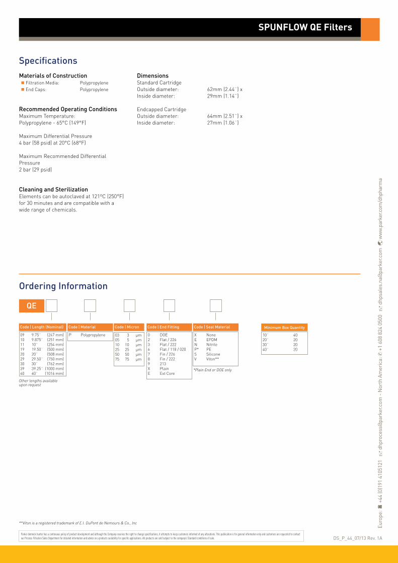
SpecificationsMaterials of Construction Filtration Media: Polypropylene End Caps: Polypropylene
Recommended Operating ConditionsMaximum Temperature:Polypropylene - 65°C (149°F) Maximum Differential Pressure 4 bar (58 psid) at 20°C (68°F)
Maximum Recommended Differential Pressure2 bar (29 psid)
Cleaning and SterilizationElements can be autoclaved at 121ºC (250°F) for 30 minutes and are compatible with a wide range of chemicals.
DimensionsStandard CartridgeOutside diameter: 62mm (2.44¨) xInside diameter: 29mm (1.14¨)
Endcapped CartridgeOutside diameter: 64mm (2.51¨) xInside diameter: 27mm (1.06¨)
Ordering Information
QE
Code ǀ Length (Nominal)
09 9.75¨ (247 mm)10 9.875¨ (251 mm)11 10¨ (254 mm)19 19.50¨ (500 mm)20 20¨ (508 mm)29 29.50¨ (750 mm)30 30¨ (762 mm)39 39.25¨ (1000 mm)40 40¨ (1016 mm)
Code ǀ Micron
03 3 µm05 5 µm10 10 µm25 25 µm50 50 µm75 75 µm
Code ǀ End FittingCode ǀ Material
0 DOE2 Flat / 2263 Flat / 2226 Flat / 118 / 0207 Fin / 2268 Fin / 2229 213X PlainE Ext Core
P Polypropylene
Code ǀ Seal Material
X NoneE EPDMN NitrileP* PES SiliconeV Viton**
SPUNFLOW QE Filters
Other lengths available upon request
*Plain End or DOE only
Minimum Box Quantity
10¨ 4020¨ 2030¨ 2040¨ 20
**Viton is a registered trademark of E.I. DuPont de Nemours & Co., Inc
Parker domnick hunter has a continuous policy of product development and although the Company reserves the right to change specifications, it attempts to keep customers informed of any alterations. This publication is for general information only and customers are requested to contact our Process Filtration Sales Department for detailed information and advice on a products suitability for specific applications. All products are sold subject to the company’s Standard conditions of sale.
Euro
pe:
+44
(0)1
91 4
1051
21
dhp
roce
ss@
park
er.c
om -
Nor
th A
mer
ica:
✆ +
1 60
8 82
4 05
00
dhp
sale
s.na
@pa
rker
.com
w
ww.
park
er.c
om/d
hpha
rma
DS_P_44_07/13 Rev. 1A

TEXFLOW precision wound depth filter cartridges are manufactured to provide considerable dirt holding capacity coupled with high flow rates and low pressure loss. TEXFLOW elements consist of a perforated support core of plastic or metal onto which yarn is wound at a pre-set rate, providing each rating of element with its own distinctive winding pattern and performance.
Polypropylene, polyester and nylon fibres offer a range of temperature resistance and chemical compatibility characteristics. For very high temperatures and for very strong oxidizing agents, baked glass fibre elements are used. Glass fibre elements are fitted with voiles and stainless steel cores as standard, other cartridges can also be fitted with voiles where necessary.
Features and Benefits
• Protection of absolute filters
• High dirt holding capacity
• Wide chemical compatibility
• Filter ratings from 1 to 100 microns
Performance Characteristics
TEXFLOW Filters
• liquid filters• wound depth filters
10¨ Size (248 mm) Cartridge
400
350
300
250
200
150
100
50
0
Diff
eren
tial
Pre
ssur
e (m
bar)
6
5
4
3
2
1
0
Diff
eren
tial
Pre
ssur
e (p
sid)
0 10 20 30
Flow (L / min) for water @ 20 °C and 1 cp
5 µm
1 µm
10 µm
25 µm

SpecificationsMaterials of Construction Filtration Media: Polyester (Various yarns) Polypropylene Glass Fibre Washed Polypropylene Nylon Inner Support Core: Polyester Polypropylene 316 Stainless Steel
Recommended Operating ConditionsMaximum Temperaturewith stainless core: Polypropylene : 93 °C (199 °F) Polyester : 121 °C (250 °F) Glass Fibre : 399 °C (750 °F)
with polypropylene core: Polypropylene : 60 °C (140 °F) Polyester : 60 °C (140 °F)
Maximum Operating Pressure4 barg (58 psi)
Recommended Changeout Pressure2 barg (29 psi)
Ordering Information
TEXFLOW Filters
E
Code ǀ Length (Nominal)
04 4¨ (100 mm)05 5¨ (125 mm)06 6¨ (160 mm)09 9.75¨ (248 mm)10 9.875¨ (251 mm)11 10¨ (254 mm)19 19.75¨ (500 mm)20 20¨ (508 mm)29 29.50¨ (750 mm)30 30¨ (762 mm)39 39.25¨ (1000 mm)40 40¨ (1016 mm)
Code ǀ Micron
01 1 µm05 5 µm10 10 µm20 20 µm50 50 µm75 75 µm99 100 µm
Code ǀ Yarn Code ǀ Core Type
01 Polyester02 Polypropylene06 Glass Fibre07 Nylon09 Washed Polypropylene
1 Polyester2 Polypropylene5 316 Stainless Steel
Code ǀ End Fitting
0 DOE2 Flat / 2263 Flat / 2227 Fin / 2268 Fin / 2229 213
Cartridges
Code ǀ Diameter
1 62 mm 2 50 mm6 100 mm
As with any addition to a process system, it is important to flush through new filter cartridges before running ‘on line’. Standard polypropylene cartridges contain traces of an FDA Glycol Ester Spin Finish which can cause ‘foaming’ when new. Where this may be a problem, washed polypropylene elements are recommended.
Parker domnick hunter has a continuous policy of product development and although the Company reserves the right to change specifications, it attempts to keep customers informed of any alterations. This publication is for general information only and customers are requested to contact our Process Filtration Sales Department for detailed information and advice on a products suitability for specific applications. All products are sold subject to the company’s Standard conditions of sale.
Euro
pe:
+44
(0)1
91 4
1051
21
dhp
roce
ss@
park
er.c
om -
Nor
th A
mer
ica:
✆ +
1 60
8 82
4 05
00
dhp
sale
s.na
@pa
rker
.com
w
ww.
park
er.c
om/d
hpha
rma
DS_P_45_01/14 Rev. 1B

PROPOR LR filters have been specifically designed for high flow and effective removal of Ralstonia pickettii and other diminutive organisms.
A number of studies have concluded that not all microorganisms are removed by 0.2 micron rated membranes under all conditions. PROPOR LR filters use a 0.1 micron rated membrane, which can remove diminutive organisms, while maintaining flow rates typical of a 0.2 micron filtration system.
Ralstonia pickettii is one organism that has frequently been shown to penetrate a 0.2 micron rated membrane and is a common contaminant in purified water systems. PROPOR LR filters have been validated directly against the removal of Ralstonia pickettii.
Features and Benefits
Cartridge flow rates
• Fully correlated against Ralstonia pickettii and integrity testable
• Increases retention efficiency whilst maintaining existing 0.2 micron rated system size
• Up to 2.5 times higher flow rate than competitive 0.1 micron rated filters
• MURUS and DEMICAPs can be gamma-irradiated and autoclaved
Performance Characteristics
PROPOR LR Filters
• liquid filters• polyethersulphone
Note: PROPOR and DEMICAP are registered trademarks of Parker Hannifin Corporation.
300
250
200
150
100
50
0
Diff
eren
tial
Pre
ssur
e (m
bar)
4
3
2
1
0
Diff
eren
tial
Pre
ssur
e (p
si)
0 2 4 6 8
Flow (L / min) for liquid @ 20 °C and 1 cp
Flow (gpm (US))0 0.5 1.0 1.5 2.0
MURUS flow rates (10¨ Size (250 mm))
200
150
100
50
0
Diff
eren
tial
Pre
ssur
e (m
bar)
3
2
1
0
Diff
eren
tial
Pre
ssur
e (p
si)
0 2 4 6 8
Flow (L / min) for liquid @ 20 °C and 1 cp
Flow (gpm (US))0 0.5 1.0 1.5 2.0
DEMICAP flow rates
600
500
400
300
200
100
0
Diff
eren
tial
Pre
ssur
e (m
bar)
8
7
6
5
4
3
2
1
0
Diff
eren
tial
Pre
ssur
e (p
si)
0 2 4 6 8
Flow (L / min) for liquid @ 20 °C and 1 cp
E Size
B Size
A Size
Flow (gpm (US))0 0.5 1.0 1.5 2.0
B Size
K Size
10¨ (250 mm)
A Size

SpecificationsMaterials of Construction Filtration Membrane: Polyethersulphone Upstream Support: Polyester Downstream Support: Polyester
Filter Cartridges Inner Support Core: Polypropylene Outer Protection Cage: Polypropylene End Caps: Nylon End Caps Insert: 316L Stainless Steel
MURUS Disposable Filter Capsules Core: Polypropylene Sleeve: Polypropylene End Caps Insert: 316L Stainless Steel Standard o-rings/gaskets: Silicone Capsule Body: Polypropylene Capsules Vent Seals: Silicone
DEMICAP Filter Capsules Core: Polypropylene Sleeve: Polypropylene End Caps: Nylon Capsule Body: Nylon Capsules Vent Seals: Silicone Filling Bell: Polycarbonate
Syringe Filters Body: Polypropylene
Recommended Operating ConditionsFilter CartridgesUp to 70 °C (158 °F) continuous operating temperature and higher short-term temperatures during CIP to the following limits:
MURUS Disposable Filter CapsulesUp to 25 °C ( 77 °F) @ 5.5 barg (79.7 psig)Up to 60 °C (140 °F) @ 2.8 barg (40.6 psig)
Parker Hannifin certify that this product complies with the European Council Pressure Equipment Directive (PED) 97/23/EC Article 3, Paragraph 3 - Sound Engineering Practice (SEP). This product is intended for use with Group 1 & 2 Dangerous and Harmless Liquids and Group 2 Harmless Gases at the operating conditions stated in this document : In compliance with PED Article 3, Paragraph 3, SEP, this product does not bear the CE mark.
DEMICAP Filter CapsulesUp to 40 °C (104 °F) at line pressures up to 5.0 barg (72 psig).
Effective Filtration Area (EFA)10¨ (250 mm): 0.55 m2 (5.92 ft2)K Size: 0.26 m2 (2.79 ft2)A Size: 0.20 m2 (2.15 ft2)B Size: 0.10 m2 (1.07 ft2)E Size: 0.05 m2 (0.53 ft2)Syringe ø50 mm: 14.50 cm2 (2.25 in2)
Sterilization
PROPOR LR filter cartridges can be sanitized with hot water at up to 90 °C (194 °F) and are compatible with a wide range of chemicals.
For detailed operational procedures and advice on cleaning and sterilization, please contact the Technical Support Group through your usual Parker domnick hunter contact. Biological SafetyMaterials conform to the relevant requirements of 21CFR Part 177 and current USP Plastics Class VI - 121 °C and ISO10993 equivalents.
Quality StandardsPharmaceutical grade products are manufactured in accordance with cGMP, 100% flushed with pharmaceutical grade purified water and integrity tested prior to despatch. A sample of each lot is tested to demonstrate conformity to validated claims.
Gamma-IrradiationPROPOR LR MURUS & DEMICAP disposable filters can be gamma-irradiated up to a maximum dosage of 40 kGy.
Temperature Max. Forward dP °C °F (bar) (psi)
20 68 5.0 72.5
40 104 4.0 58.0
60 140 3.0 43.5
80 176 2.0 29.0
90 194 1.7 24.6
PROPOR LR Filters
Autoclave Steam-in-Place Cycles Temp Cycles Temp (30 min.)
Cartridges 10 130 °C (266 °F) 30 130 °C (266 °F)
MURUS 5 130 °C (266 °F) - -
DEMICAP 10 130 °C (266 °F) - -
Syringe 1 130 °C (266 °F) - -

Performance CharacteristicsTOC / ConductivityThe filtrate quality from a 10¨ (250 mm) PROPOR LR conforms to the requirements of current USP <643> (TOC) and USP <645> (conductivity) within the first 200 ml flush of purified water.
EndotoxinsAqueous extracts from the 10¨ (250 mm) PROPOR LR contain < 0.25 EU / ml when tested in accordance with the Limulus Amoebocyte Lysate test.
Non-Volatile Extractables (NVE)Total NVEs extracted in the first 5 litre flush of purified water for a 10¨ (250 mm)cartridge are <10 mg.
Total NVEs extracted in the first 5 litre flush of purified water for an A size 7.9¨ (200 mm) DEMICAP capsule are <5 mg.
Pharmaceutical ValidationA full validation guide is available upon request from Laboratory Services Group (LSG).
Oxidizable SubstancesPROPOR LR filter cartridges meet current USP and EP quality standards for sterile purified water for oxidizable substances following a <1 litre water flush.
Integrity Test DataAll filters are integrity testable to the following limits when wet with water (diffusional flow) and 60 / 40 : IPA / Water (bubble point) using air as the test gas.
(Maximum allowable diffusional flows are directly correlated to full retention of Ralstonia pickettii.)
Retention CharacteristicsPROPOR LR filters are validated by bacterial challenge testing with Ralstonia pickettii and Brevundimonas diminuta to current ASTM F838-05 methodology (107 organisms / cm2 EFA minimum) with typical in-house challenge levels being 1011 organisms per 10¨ (250 mm) filter cartridge.
PROPOR LR Filters
Micron Rating 0.1
Filter Cartridges / MURUS / DEMICAP
Min. Bubble Point (barg) 2.1
(psig) 30.0
Filter Cartridges / MURUS / DEMICAP / Syringe Filters
Diffusional Flow (barg) 4.2
Test Pressure (psig) 61.0
Filter Cartridges / MURUS / DEMICAP / Syringe Filters
Max. Diffusional Flow (10¨) 27.0
(ml / min) (K) 12.6
(A) 10.1
(B) 4.9
(E) 2.1
Differential pressure comparison of 10¨ (250 mm) sterilising grade filters
450
400
350
300
250
200
150
100
50
0Diff
eren
tial
Pre
ssur
e @
10
L /
min
(mba
r)
0.1 µm Typical 0.1 µm 0.2 µm PROPOR PVDF PES PVDF LR
Membrane Material

PROPOR LR Filters
Ordering Information
ZCLR - -
Code ǀ Length (Nominal)
B* 2.5¨ (65 mm)A* 5¨ (125 mm)K 5¨ (125 mm)1 10¨ (250 mm)2 20¨ (500 mm)3 30¨ (750 mm)4 40¨ (1000 mm)
Code ǀ Micron
010 0.1 µm
Code ǀ Variant
P Pharmaceutical
Code ǀ O-rings
E EPDMS SiliconeV Viton
ZLLR -
Code ǀ Length (Nominal)
K 5¨ (125 mm)1 10¨ (250 mm)2 20¨ (500 mm)3 30¨ (750 mm)
Code ǀ Micron
010 0.1 µm
Code ǀ Inlet Connection
A 3/4¨ Tri-ClampB 11/2¨ Tri-ClampD 1¨ HosebarbT 1¨ Tri-Clamp
Code ǀ Variant
P Pharmaceutical
MURUS Capsules
Code ǀ Outlet Connection
A 3/4¨ Tri-ClampB 11/2¨ Tri-ClampD 1¨ HosebarbT 1¨ Tri-Clamp
Code ǀ Grade
N Non-sterileS Pre-sterilized γ (>25 kGy)
Code ǀ Design
L In-LineT* T-Port
Cartridges
ZELR -
Code ǀ Length (Nominal)
E 4.4¨ (113 mm)B 5.5¨ (140 mm)A 7.9¨ (200 mm)
Code ǀ Micron
010 0.1 µm
Code ǀ Inlet Connection
T 1¨ Tri-ClampN 1/2¨ NPT MaleH 1/2¨ HosebarbG Stepped HosebarbM 1/4¨ NPT MaleQ Walther QCR Grommel / QC
Code ǀ Variant
P Pharmaceutical
DEMICAP Capsules
Code ǀ Outlet Connection
T 1¨ Tri-ClampN 1/2¨ NPT MaleH 1/2¨ HosebarbG Stepped HosebarbM 1/4¨ NPT MaleQ Walther QCR Grommel / QC
Code ǀ Grade
N Non-sterileS Pre-sterilized γ (>25 kGy)
Code ǀ Pack N°
3 Pack of 3
Code ǀ O-rings
E EPDMS* SiliconeV Viton
-
- -
Code ǀ Accessory
FB Filling Bell
-
G & H connections only
ZSLR -
Code ǀ Diameter
050 50 mm
Code ǀ Micron
010 0.1 µm
Code ǀ Variant
P Pharmaceutical
Syringe Filters
Code ǀ Grade
N Non-sterile
Code ǀ Options
S Standard
-
Code ǀ Pack N°
025 25 per box
DS_P_06_01/11 Rev. 4A
* Only available with a 1¨ Tri-Clamp
Code ǀ Inlet Connection
F Female Luer LockG Stepped Hosebarb
Code ǀ Outlet Connection
F Female Luer LockG Stepped Hosebarb
Code ǀ Endcap (10¨)
C BF / 226 BayonetD Fin / 222E Flat Top / 222G Recess / 222R BF / 222 Bayonet
Code ǀ Endcap (Demi)
T TRUESEALY Demi StubZ Demi A & B Std
* Supplied in packs of 3.
* Silicone o-ring supplied as standard without having to specify the ‘S’ code.
Parker domnick hunter has a continuous policy of product development and although the Company reserves the right to change specifications, it attempts to keep customers informed of any alterations. This publication is for general information only and customers are requested to contact our Process Filtration Sales Department for detailed information and advice on a products suitability for specific applications. All products are sold subject to the company’s Standard conditions of sale.
Euro
pe:
+44
(0)1
91 4
1051
21
dhp
roce
ss@
park
er.c
om -
Nor
th A
mer
ica:
✆ +
1 60
8 82
4 05
00
dhp
sale
s.na
@pa
rker
.com
w
ww.
park
er.c
om/d
hpha
rma

TETPOR LIQUID filters are particularly suitable for sterilization and particulate removal from aggressive chemicals (including acids, bases and solvents) within a wide range of critical processing industries.
The superior performance, strength and durability of TETPOR LIQUID filters stems from the use of a single layer, high security PTFE membrane, which has a high dirt holding capacity due to its high voids volume. This results in low pressure drops and long service life.
High flow rates are achieved due to the optimized pleat pack density and the superior design construction of TETPOR LIQUID filters.
Features and Benefits
• Superior chemical resistance of PTFE membrane combined with polypropylene hardware
• Integrity tested prior to despatch
• Validated to ASTM F838-05 methodology
• Comprehensive range of end cap configurations for retrofitting
Performance Characteristics
TETPOR LIQUID Filters
• liquid filters• PTFE
Note: TETPOR is a registered trademark of Parker Hannifin Corporation.
10¨ Size (250 mm) Cartridge
300
250
200
150
100
50
0
Diff
eren
tial
Pre
ssur
e (m
bar)
4
3
2
1
0
Diff
eren
tial
Pre
ssur
e (p
si)
0 5 10 15 20 25 30
Flow (L / min) for liquid @ 20 °C and 1 cp
For K size for a given flow rate multiply 10¨ size differential pressure by 2
B Size (65 mm) Cartridge and Capsule
For A size for a given flow rate divide B size differential pressure by 2For E sie for a given flow rate multiply B size differential pressure by 2
0.1 µm
0.2 µm
0.45 µm
1.0 µm
450
400
350
300
250
200
150
100
50
0
Diff
eren
tial
Pre
ssur
e (m
bar)
6
5
4
3
2
1
0
Diff
eren
tial
Pre
ssur
e (p
si)
0 2 4 6 8 10
Flow (L / min) for liquid @ 20 °C and 1 cp
0.1 µm
0.2 µm
0.45 µm
1.0 µm

TETPOR LIQUID Filters
SpecificationsMaterials of Construction Filtration Membrane: PTFE Upstream Support: Polypropylene Downstream Support: Polypropylene
Filter Cartridges Inner Support Core: Polypropylene Outer Protection Cage: Polypropylene End Caps: Polypropylene End Caps Insert: 316L Stainless Steel *Not available in B endcap variant
Standard o-rings/gaskets: Viton
MURUS Disposable Filter Capsules Core: Polypropylene Sleeve: Polypropylene End Caps Insert: 316L Stainless Steel Standard o-rings/gaskets: Silicone Capsule Body: Polypropylene Capsules Vent Seals: Silicone
DEMICAP Filter Capsules Core: Polypropylene Sleeve: Polypropylene End Caps: Polypropylene Capsule Body: Polypropylene Capsules Vent Seals: Silicone Filling Bell: Polycarbonate
Syringe Filters Body: Polypropylene
Recommended Operating ConditionsFilter CartridgesUp to 70 °C (158 °F) continuous operating temperature and higher short-term temperatures during CIP to the following limits:
MURUS Disposable Filter CapsulesUp to 25 °C ( 77 °F) @ 5.5 barg (79.7 psig)Up to 60 °C (140 °F) @ 2.8 barg (40.6 psig)
Parker Hannifin certify that this product complies with the European Council Pressure Equipment Directive (PED) 97/23/EC Article 3, Paragraph 3 - Sound Engineering Practice (SEP). This product is intended for use with Group 1 & 2 Dangerous and Harmless Liquids and Group 2 Harmless Gases at the operating conditions stated in this document : In compliance with PED Article 3, Paragraph 3, SEP, this product does not bear the CE mark.
DEMICAP Filter CapsulesUp to 40 °C (104 °F) at line pressures up to 5.0 barg (72 psig).
Effective Filtration Area (EFA)10¨ (250 mm): 0.77 m2 (8.28 ft2)K Size: 0.36 m2 (3.87 ft2)A Size: 0.25 m2 (2.69 ft2)B Size: 0.12 m2 (1.29 ft2)E Size: 0.06 m2 (0.64 ft2)Syringe ø50 mm: 14.50 cm2 (2.25 in2)
Sterilization
TETPOR LIQUID filter cartridges can be sanitized with hot water at up to 90 °C (194 °F) and are compatible with a wide range of chemicals.
For detailed operational procedures and advice on cleaning and sterilization, please contact the Technical Support Group through your usual Parker domnick hunter contact. Biological SafetyMaterials conform to the relevant requirements of 21CFR Part 177 and current USP Plastics Class VI - 121 °C and ISO10993 equivalents.
Quality StandardsPharmaceutical grade products are manufactured in accordance with cGMP, 100% flushed with pharmaceutical grade purified water and integrity tested prior to despatch. A sample of each lot is tested to demonstrate conformity to validated claims.
Temperature Max. Forward dP °C °F (bar) (psi)
20 68 5.0 72.5
40 104 4.0 58.0
60 140 3.0 43.5
80 176 2.0 29.0
90 194 1.7 24.6
Autoclave Steam-in-Place Cycles Temp Cycles Temp (30 min.)
Cartridges 120 142 °C (287.6 °F) 120 142 °C (287.6 °F)
MURUS 5 130 °C (266 °F) - -
DEMICAP 10 135 °C (275 °F) - -
Syringe 1 130 °C (266 °F) - -

Performance CharacteristicsTOC / ConductivityThe filtrate quality from a 10¨ (250 mm) TETPOR LIQUID conforms to the requirements of current USP <643> (TOC) and USP <645> (conductivity).
EndotoxinsAqueous extracts from the 10¨ (250 mm) TETPOR LIQUID contain < 0.25 EU / ml when tested in accordance with the Limulus Amoebocyte Lysate test.
Non-Volatile Extractables (NVE)Total NVEs extracted in the first 5 litre flush of purified water for a 10¨ (250 mm)cartridge are <5 mg.
Pharmaceutical ValidationA full validation guide is available upon request from Laboratory Services Group (LSG).
Oxidizable SubstancesTETPOR LIQUID filter cartridges meet current USP and EP quality standards for sterile purified water for oxidizable substances following a <1 litre water flush.
Integrity Test DataAll filters are integrity testable to the following limits when wet with 60 / 40 IPA / Water and using air as the test gas.
Retention CharacteristicsTETPOR LIQUID filter cartridges are validated by bacterial challenge testing with Brevundimonas diminuta to current ASTM F838-05 methodology (107 organisms / cm2 EFA minimum) with typical in-house challenge levels being 1011 organisms per 10¨ (250 mm) filter cartridge.
TETPOR LIQUID Filters
Micron Rating 0.1 0.2 0.45 1.0
Filter Cartridges / MURUS / DEMICAP / Syringe Filters
Min. Bubble Point (barg) 1.3 1.0 0.7 -
(psig) 18.8 14.5 10.1 -
Filter Cartridges / MURUS / DEMICAP / Syringe Filters
Diffusional Flow (barg) 1.0 0.8 0.4 -
Test Pressure (psig) 14.5 11.6 5.8 -
Filter Cartridges / MURUS / DEMICAP / Syringe Filters
Max. Diffusional Flow (10¨) 27.0 18.0 18.0 -
(ml / min) (K) 12.7 8.5 8.5 -
(A) 9.0 6.0 6.0 -
(B) 4.5 3.0 3.0 -
(E) 2.3 1.5 1.5 -

TETPOR LIQUID Filters
Ordering Information
ZLMT -
Code ǀ Length (Nominal)
K 5¨ (125 mm)1 10¨ (250 mm)2 20¨ (500 mm)3 30¨ (750 mm)
Code ǀ Micron
010 0.1 µm020 0.2 µm045 0.45 µm100 1.0 µm
Code ǀ Inlet Connection
A 3/4¨ Tri-ClampB 11/2¨ Tri-ClampD 1¨ HosebarbT 1¨ Tri-Clamp
Code ǀ Variant
P Pharmaceutical
MURUS Capsules
Code ǀ Outlet Connection
A 3/4¨ Tri-ClampB 11/2¨ Tri-ClampD 1¨ HosebarbT 1¨ Tri-Clamp
Code ǀ Grade
N Non-sterile
Code ǀ Design
L In-LineT* T-Port
Cartridges
DEMICAP Capsules
Code ǀ O-rings
E EPDMS* SiliconeV Viton
- -
Syringe Filters
ZCMT -
Code ǀ Length (Nominal)
B* 2.5¨ (65 mm)A* 5¨ (125 mm)K 5¨ (125 mm)1 10¨ (250 mm)2 20¨ (500 mm)3 30¨ (750 mm)4 40¨ (1000 mm)
Code ǀ Micron
010 0.1 µm020 0.2 µm045 0.45 µm100 1.0 µm
Code ǀ O-rings
E EPDMP PTFE Encapsulated SiliconeS SiliconeV* Viton
Code ǀ Variant
L LiquidP PharmaceuticalS Steam Sterilizable
ZEMT -
Code ǀ Length (Nominal)
E 4.4¨ (113 mm)B 5.5¨ (140 mm)A 7.9¨ (200 mm)
Code ǀ Micron
010 0.1 µm020 0.2 µm045 0.45 µm100 1.0 µm
Code ǀ Inlet Connection
T 1¨ Tri-ClampN 1/2¨ NPT MaleH 1/2¨ HosebarbG Stepped HosebarbM 1/4¨ NPT MaleQ Walther QCR Grommel / QCV 3/8¨ NPT Female
Code ǀ Variant
P Pharmaceutical
Code ǀ Outlet Connection
T 1¨ Tri-ClampN 1/2¨ NPT MaleH 1/2¨ HosebarbG Stepped HosebarbM 1/4¨ NPT MaleQ Walther QCR Grommel / QCV 3/8¨ NPT Female
Code ǀ Pack N°
3 Pack of 3
-
Code ǀ Accessory
FB Filling Bell
G & H connections only
Code ǀ Grade
N Non-Sterile
ZSMT -
Code ǀ Diameter
050 50 mm
Code ǀ Micron
020 0.2 µm
Code ǀ Variant
P Pharmaceutical
Code ǀ Grade
N Non-sterile
Code ǀ Options
S Standard
-
Code ǀ Pack N°
025 25 per box
DS_P_08_01/11 Rev. 4A
* Only available with a 1¨ Tri-Clamp
Code ǀ Inlet Connection
F Female Luer LockG Stepped Hosebarb
Code ǀ Outlet Connection
F Female Luer LockG Stepped Hosebarb
* Viton o-ring supplied as standard without having to specify the ‘V’ code.
Code ǀ Endcap (10¨)
B* dh DOEC BF / 226 BayonetD Fin / 222E Flat Top / 222G Recess / 222R BF / 222 Bayonet
Code ǀ Endcap (Demi)
SK RetrofitT TRUESEALY Demi StubZ Demi A & B Std
* Supplied in packs of 3.
* EPDM gaskets supplied as standard Note: Viton supplied as standard on all other endcap options.
* Silicone o-ring supplied as standard without having to specify the ‘S’ code.
Parker domnick hunter has a continuous policy of product development and although the Company reserves the right to change specifications, it attempts to keep customers informed of any alterations. This publication is for general information only and customers are requested to contact our Process Filtration Sales Department for detailed information and advice on a products suitability for specific applications. All products are sold subject to the company’s Standard conditions of sale.
Euro
pe:
+44
(0)1
91 4
1051
21
dhp
roce
ss@
park
er.c
om -
Nor
th A
mer
ica:
✆ +
1 60
8 82
4 05
00
dhp
sale
s.na
@pa
rker
.com
w
ww.
park
er.c
om/d
hpha
rma

TETPOR PLUS filters are manufactured entirely from fluoropolymers making them extremely resistant to a wide range of aggressive chemicals.
TETPOR PLUS filter cartridges have been specifically designed for the filtration of liquids and gases in the bulk pharmaceutical, chemical and biopharmaceutical industry where particulate removal, bioburden reduction and guaranteed sterility is required.
The increasing use of ozonation for the treatment of WFI systems has highlighted compatibility issues with vent filters based on standard polypropylene components. The introduction of a fully validated 0.2 micron sterilizing grade TETPOR PLUS filter cartridge provides guaranteed long term performance in these applications with the additional benefit that the filters integrity can be validated by the water intrusion test method.
The high voids volume single layer PTFE membrane ensures an excellent combination of flow rate and retention.
Features and Benefits
10¨ Size (250 mm) Cartridge
• Sterile filtration of oxygen / oxygen enriched feeds in cell culture
• Exceptional resistance to solvents and oxidative environments
• Ideal for sterile venting on ozonated water systems
• Fully validated to ASTM F838-05 for sterilizing grade filters
• PTFE membrane
• Available in a wide range of micron ratings to suit all applications
Performance Characteristics
TETPOR PLUS Filters
• liquid filters• polytetrafluoroethylene
Note: TETPOR is a registered trademark of Parker Hannifin Corporation.
200
150
100
50
0
Diff
eren
tial
Pre
ssur
e (m
bar) 2.5
2.0
1.5
1.0
0.5
0
Diff
eren
tial
Pre
ssur
e (p
si)
0 5 10 15 20 25
Flow (L / min) for liquid @ 20 °C and 1 cp
10¨ Size (250 mm) Cartridge
100
90
80
70
60
50
40
30
20
10
0
Diff
eren
tial
Pre
ssur
e (m
bar)
1.4
1.2
1.0
0.8
0.6
0.4
0.2
0
Diff
eren
tial
Pre
ssur
e (p
si)
0 20 40 60 80 100 120
Flow (m3 / hr) for air @ 20 °C
0.1 µm
0.2 µm
0.45 µm
1.0 µm
0.2 µm

SpecificationsMaterials of Construction Filtration Membrane: Polytetrafluoroethylene Upstream Support: Polytetrafluoroethylene Downstream Support: Polytetrafluoroethylene Inner Support Core: PFA Outer Protection Cage: PFA End Caps: PFA
Biological SafetyMaterials conform to the relevant requirements of 21CFR Part 177 and current USP Plastics Class VI - 121 °C and ISO10993 equivalents.
Recommended Operating ConditionsUp to 125 °C (257 °F) continuous operating temperature and higher short-term temperatures during CIP to the following limits:
Effective Filtration Area (EFA)10¨ (250 mm) Up to 0.63 m2 (6.78 ft2)K Size (125 mm) Up to 0.32 m2 (3.44 ft2)
Cleaning and SterilizationTETPOR PLUS cartridges can be repeatedly steam sterilized in situ or autoclaved at up to 142 °C (287.6 °F) for a maximum of 30 cycles. Retention CharacteristicsTETPOR PLUS filter cartridges are validated by bacterial challenge testing with Brevundimonas diminuta to current ASTM F838-05 methodology (107 organisms / cm2 EFA minimum) with typical in-house challenge levels being 1011 organisms per 10¨ (250 mm) module.
Integrity Test DataThe following is the integrity test information for the micron ratings available within the TETPOR PLUS product range. Diffusional flow and bubble point values are given for cartridges wetted in 60:40 v/v IPA:Water solution.
Pharmaceutical ValidationA full validation guide is available upon request from Laboratory Services Group (LSG).
Temperature Max. Forward dP °C °F (bar) (psi)
20 68 5.5 80.0
75 167 3.8 55.0
125 257 2.0 30.0
Micron Rating 0.1 0.2 0.45 1.0
Diffusional Flow (barg) 1.45 1.0 0.45 3.0
Test Pressure (psig) 19.0 15.0 0.5 0.2
Max. Diffusional Flow (10¨) 35.0 16.5 50.0 -
(ml / min) (K) 16.3 7.7 23.3 -
Min. Bubble Point (barg) 1.45 1.0 0.48 3.0
(psig) 19.0 15.0 0.5 0.2
Water Intrusion (barg) - 2.5 - -
Test Pressure (psig) - 36.3 - -
Max. Water Intrusion (10¨) - 13.5 - -
(ml / 10 min) (K) - 6.4 - -
Ordering Information
ZCTP - -
Code ǀ Length (Nominal)
K 5¨ (125 mm)1 10¨ (250 mm)2 20¨ (500 mm)3 30¨ (750 mm)4 40¨ (1000 mm)
Code ǀ Micron
010 0.1 µm020 0.2 µm045 0.45 µm100 1.0 µm
Code ǀ Endcap (10¨)
CF Flat Top / 226C BF / 226 BayonetE Flat Top / 222D Fin / 222
Code ǀ Variant
P Pharmaceutical
Code ǀ O-rings
P FEP Encapsulated VitonK KalrezC ChemrazS Silicone
TETPOR PLUS Filters
Code ǀ Insert Option
N* No Insert
-
*Omit if 316L stainless steel insert required
Parker domnick hunter has a continuous policy of product development and although the Company reserves the right to change specifications, it attempts to keep customers informed of any alterations. This publication is for general information only and customers are requested to contact our Process Filtration Sales Department for detailed information and advice on a products suitability for specific applications. All products are sold subject to the company’s Standard conditions of sale.
Euro
pe:
+44
(0)1
91 4
1051
21
dhp
roce
ss@
park
er.c
om -
Nor
th A
mer
ica:
✆ +
1 60
8 82
4 05
00
dhp
sale
s.na
@pa
rker
.com
w
ww.
park
er.c
om/d
hpha
rma
DS_P_46_07/13 Rev. 1A

High quality steam for sterilization and heating purposes is a key element of many pharmaceutical manufacturing systems, ensuring effective and continuous operation of the process.
Parker domnick hunter STEAM filters are designed to provide high quality particulate removal in process steam (available with compliance to 3A Standard 609-03) together with high flow rates and dirt-holding capacity, thereby allowing long system lifetime and cost-effective operation.
STEAM Filters
• steam filters• 316L stainless steel
Features and Benefits
• 316L stainless steel filter cartridges
• Exceptionally high flow rates
• Available in compliance with 3A Standard 609-03 (culinary grade) 1 micron
• High dirt holding capacity
• ‘JUMBO’ filter configuration ensures maximum utilization of pipework capacity

STEAM Filters
Which Filter for Which Application ?
Process Steam
•Direct from boiler
•No direct contact with product being manufactured
Culinary Steam (3A Standard 609-03)
•95% retention of >2 micron particles in the liquid phase
•Manufactured from 300 series stainless steel
•Any additives to the boiler feed should conform to CFR Title 21, Chapter 1, Part 173, Section 173.310
Clean Steam (HTM 2031:1997)*
•Condensate to WFI standards
Applications
•General heating
•Steam jackets
•Bio waste kill systems
Applications
•Used in direct contact with food
•Direct contact with food processing equipment and HVAC systems
Applications
•Pharmaceutical products
•Pharmaceutical plant HVAC systems
Cartridges
•Required if steam is used to sterilize liquid and gas cartridge filters•Selection dependant on flow parameters
Cartridges
•Selection dependant on flow parameters
Cartridges
•For removal of magnetite particles generated from stainless steel pipes due to corrosive purity of steam
Sintered 25 µm(Selection Criteria)
Use for relatively low flow rates
Pleated 5 µm(Selection Criteria)
High flow rate and dirt holding capacity
Sintered 1 µm(Selection Criteria)
Use for relatively low flow rates
Culinary 1 µm(Selection Criteria)
Used to maximize steam capacity of pipe
JUMBO Filters(Selection Criteria)
Highest available capacity
HIGH FLOW TETPOR II(Selection Criteria)
PTFE membrane 100% removal of magetite particles generated from stainless steel pipes
Culinary 1µm(Selection Criteria)
To conform to HTM 2031 Point of Use filter rated at <5 µm
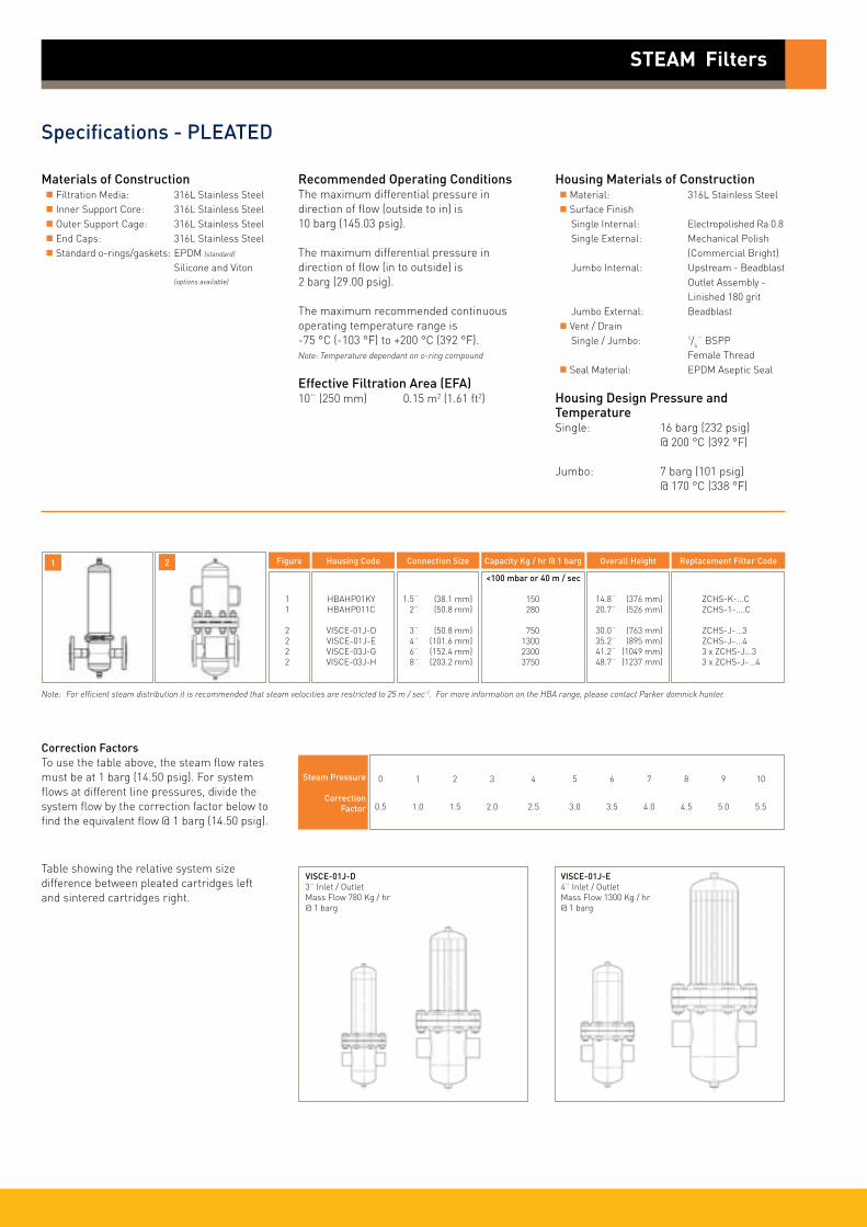
Specifications - PLEATED
STEAM Filters
Materials of Construction Filtration Media: 316L Stainless Steel Inner Support Core: 316L Stainless Steel Outer Support Cage: 316L Stainless Steel End Caps: 316L Stainless Steel Standard o-rings/gaskets: EPDM (standard)
Silicone and Viton (options available)
Recommended Operating ConditionsThe maximum differential pressure in direction of flow (outside to in) is 10 barg (145.03 psig).
The maximum differential pressure in direction of flow (in to outside) is 2 barg (29.00 psig).
The maximum recommended continuous operating temperature range is -75 °C (-103 °F) to +200 °C (392 °F).Note: Temperature dependant on o-ring compound
Effective Filtration Area (EFA)10¨ (250 mm) 0.15 m2 (1.61 ft2)
Housing Materials of Construction Material: 316L Stainless Steel Surface Finish Single Internal: Electropolished Ra 0.8 Single External: Mechanical Polish (Commercial Bright) Jumbo Internal: Upstream - Beadblast Outlet Assembly - Linished 180 grit Jumbo External: Beadblast Vent / Drain Single / Jumbo: 1/4¨ BSPP Female Thread Seal Material: EPDM Aseptic Seal
Housing Design Pressure and TemperatureSingle: 16 barg (232 psig) @ 200 °C (392 °F)
Jumbo: 7 barg (101 psig) @ 170 °C (338 °F)
Housing Code
HBAHP01KYHBAHP011C
VISCE-01J-DVISCE-01J-EVISCE-03J-GVISCE-03J-H
Connection Size
1.5¨ (38.1 mm) 2¨ (50.8 mm)
3¨ (50.8 mm) 4¨ (101.6 mm) 6¨ (152.4 mm) 8¨ (203.2 mm)
Capacity Kg / hr @ 1 barg
<100 mbar or 40 m / sec
150 280 750 1300 2300 3750
Overall Height
14.8¨ (376 mm) 20.7¨ (526 mm)
30.0¨ (763 mm) 35.2¨ (895 mm) 41.2¨ (1049 mm) 48.7¨ (1237 mm)
Replacement Filter Code
ZCHS-K-...C ZCHS-1-....C
ZCHS-J-...3 ZCHS-J-...4 3 x ZCHS-J...3 3 x ZCHS-J-...4
Note: For efficient steam distribution it is recommended that steam velocities are restricted to 25 m / sec-1. For more information on the HBA range, please contact Parker domnick hunter.
Steam Pressure
Correction Factor
0 1 2 3 4 5 6 7 8 9 10
0.5 1.0 1.5 2.0 2.5 3.0 3.5 4.0 4.5 5.0 5.5
Correction FactorsTo use the table above, the steam flow rates must be at 1 barg (14.50 psig). For system flows at different line pressures, divide the system flow by the correction factor below to find the equivalent flow @ 1 barg (14.50 psig).
Figure
11
2222
Table showing the relative system size difference between pleated cartridges left and sintered cartridges right.
VISCE-01J-D3¨ Inlet / OutletMass Flow 780 Kg / hr @ 1 barg
VISCE-01J-E4¨ Inlet / OutletMass Flow 1300 Kg / hr @ 1 barg
1 2

Ordering Information
ZCSS -
Code ǀ Length (Nominal)
B 2.5¨ (65 mm)A 5¨ (125 mm)K 5¨ (125 mm)1 10¨ (250 mm)2 20¨ (500 mm)3 30¨ (750 mm)
Code ǀ Nominal Micron Rating (Steam)
001 1.0 µm (Culinary)025 25.0 µm
STEAM Filters
SINTERED
ZCHS -
Code ǀ Length (Nominal)
B 2.5¨ (65 mm)A 5¨ (125 mm)K 5¨ (125 mm)1 10¨ (250 mm)2 20¨ (500 mm)3 30¨ (750 mm)J JUMBO
Code ǀ Nominal Micron Rating (Steam)
001 1.0 µm (Culinary) 005 5.0 µm
PLEATED
Specifications - SINTERED
Materials of Construction Filtration Media: Sintered Stainless Steel (316L) End Caps: Stainless Steel (316L) Standard o-rings/gaskets: EPDM (standard)
Silicone and Viton (options available)
Recommended Operating ConditionsThe maximum differential pressure in direction of flow (outside to in) is 10 barg (145.03 psig).
The maximum differential pressure in direction of flow (in to outside) is 5 barg (72.51 psig).
The maximum recommended continuous operating temperature range is -75 °C (-103 °F) to +200 °C (392 °F).Note: Temperature dependant on o-ring compound
Housing Materials of Construction Material: 316L Stainless Steel Surface Finish Internal: Electropolished Ra 0.8 External: Mechanical Polish (Commercial Bright) Vent / Drain: 1/4¨ BSPP Female Thread (Supplied with Plug) Seal Material: EPDM Aseptic Seal
Housing Design Pressure and Temperature16 barg (232 psig) @ 200 °C (392 °F)
Note: For efficient steam distribution it is recommended that steam velocities are restricted to 25 m / sec-1. For more information on the HBA range, please contact Parker domnick hunter.
Steam Pressure
Correction Factor
0 1 2 3 4 5 6 7 8 9 10
0.5 1.0 1.5 2.0 2.5 3.0 3.5 4.0 4.5 5.0 5.5
Correction FactorsTo use the table above, the steam flow rates must be at 1 barg (14.50 psig). For system flows at different line pressures, divide the system flow by the correction factor below to find the equivalent flow @ 1 barg (14.50 psig).
Housing Code
HBAHP01KYHBAHP011CHBAHP012C
Connection Size
1.5¨ (38.1 mm) 2¨ (50.8 mm) 2¨ (50.8 mm)
Capacity Kg / hr @ 1 barg
<100 mbar or 40 m / sec 1 µm 25 µm
21 45 40 160 82 280
Overall Height
14.8¨ (376 mm) 20.7¨ (526 mm) 30.5¨ (776 mm)
Replacement Filter Code
ZCSSK-...C ZCSS1-....C ZCSS2-....C
Figure
111
1
-
All cartridges supplied as single items.
All cartridges supplied as single items.
Code ǀ Endcap (10¨)
B dh DOEC 226 Bayonet
Code ǀ Endcap (Demi)
T TRUESEALZ Demi A & B Std
Code ǀ Endcap (10¨)
B dh DOEC 226 Bayonet3 3¨ JUMBO4 4¨ JUMBO
Code ǀ Endcap (Demi)
T TRUESEALZ Demi A & B Std
SINTERED Stainless Steel Retrofit Cartridge Part Numbers - 1.0 µm & 25 µmParker domnick hunter
Cartridge
Retrofit Cartridge
DS-R 3/1 DS-R 3/1.4 DS-R 4/1.5 DS-R 4/2.5 DS-R 5/2.5 DS-R 5/3 DS-R 10/3 DS-R 15/3 DS-R 20/3 DS-R 30/3 DS-R 30/5
GS3/1 GS3/1.5 GS4/1.5 GS4/2.5 GS5/2.5 GS5/3 GS10/3 GS15/3 GS20/3 GS30/3 GS30/5 SS3/1 SS3/1.5 SS4/1.5 SS4/2.5 SS5/2.5 SS5/3 SS10/3 SS15/3 SS20/3 SS30/3 SS30/5
Parker domnick hunter Cartridge
Retrofit Cartridge
DS-R 02/05 DS-R 02/10 DS-R 03/05 DS-R 03/10 DS-R 04/10 DS-R 04/20 DS-R 05/20 DS-R 05/25 DS-R 07/25 DS-R 07/30 DS-R 10/30 DS-R 15/30 DS-R 20/30 DS-R 30/30 DS-R 30/50
GS02/05 GS02/10 GS03/05 GS03/10 GS04/10 GS04/20 GS05/20 GS05/25 GS07/25 GS07/30 GS10/30 GS15/30 GS20/30 GS30/30 GS30/50 SS02/05 SS02/10 SS03/05 SS03/10 SS04/10 SS04/20 SS05/20 SS05/25 SS07/25 SS07/30 SS10/30 SS15/30 SS20/30 SS30/30 SS30/50
Parker domnick hunter Cartridge
Retrofit Cartridge
PDS-R 02/05 PDS-R 02/10 PDS-R 03/05 PDS-R 03/10 PDS-R 04/10 PDS-R 04/20 PDS-R 05/20 PDS-R 05/25 PDS-R 07/25 PDS-R 07/30 PDS-R 10/30 PDS-R 15/30 PDS-R 20/30 PDS-R 30/30 PDS-R 30/50
P-GS02/05 P-GS02/10 P-GS03/05 P-GS03/10 P-GS04/10 P-GS04/20 P-GS05/20 P-GS05/25 P-GS07/25 P-GS07/30 P-GS10/30 P-GS15/30 P-GS20/30 P-GS30/30 P-GS30/50 P-SS02/05 P-SS02/10 P-SS03/05 P-SS03/10 P-SS04/10 P-SS04/20 P-SS05/20 P-SS05/25 P-SS07/25 P-SS07/30 P-SS10/30 P-SS15/30 P-SS20/30 P-SS30/30 P-SS30/50

Ordering Information
Z
Code ǀ Length (Nominal)
02 2¨ (65 mm)03 3¨ (125 mm)04 4¨ (125 mm)05 5¨ (250 mm)07 7¨ (500 mm)10 10¨ (750 mm)15 15¨ (750 mm)20 20¨ (750 mm)30 30¨ (750 mm)
Code ǀ Diameter (Nominal)
05 1¨10 1¨20 2¨25 2.5¨30 3¨50 5¨
SINTERED retrofit cartridges
All cartridges supplied as single items.
Code ǀ Endcap (10¨)
UP 2 x o-ringUR 1 x o-ring & threadUI 2 x o-ring & thread
Specifications - SINTERED retrofit cartridges
Materials of Construction Filtration Media: Sintered Stainless Steel (316L) End Caps: Stainless Steel (316L) Standard o-rings/gaskets: EPDM (standard)
Silicone and Viton (options available)
Recommended Operating ConditionsThe maximum differential pressure in direction of flow (outside to in) is 10 barg (145.03 psig).
The maximum differential pressure in direction of flow (in to outside) is 5 barg (72.51 psig).
The maximum recommended continuous operating temperature range is -75 °C (-103 °F) to +200 °C (392 °F).Note: Temperature dependant on o-ring compound
Code ǀ Micron
P 1 micronS 25 micron
Code UP Code UR Code UI
STEAM Filters
Description L D Diagram
ZP/ZS 0210 UP -
ZP/ZS 0310 UP 86 35
ZP/ZS 0305 UP - -
ZP/ZS 0410 UP 114 35
ZP/ZS 0420 UP 117 40
ZP/ZS 0520 UP 141 40
ZP/ZS 0525 UP 141 54
ZP/ZS 0725 UP 193 54
ZP/ZS 0730 UP 196 76
ZP/ZS 1030 UP 269 76
ZP/ZS 1530 UP 396 76
ZP/ZS 2030 UP 523 76
ZP/ZS 3030 UP 775 76
ZP/ZS 3050 UP 775 76
øD
L
+1
Description L D Diagram
ZP/ZS 0205 UI 75 35
ZP/ZS 0210 UI 93 35
ZP/ZS 0305 UI 89 35
ZP/ZS 0310 UI 93 35
ZP/ZS 0410 UI 121 35
ZP/ZS 0420 UI 127 40
ZP/ZS 0520 UI 151 40
ZP/ZS 0525 UI 151 54
ZP/ZS 0725 UI 203 54
ZP/ZS 0730 UI 206 76
ZP/ZS 1030 UI 279 76
ZP/ZS 1530 UI 406 76
ZP/ZS 2030 UI 533 76
ZP/ZS 3030 UI 785 76
ZP/ZS 3050 UI 785 130
øD
L
+1
G
Description L D Diagram
ZP/ZS 0310 UR 88 40
ZP/ZS 0315 UR 88 40
ZP/ZS 0415 UR 124 40
ZP/ZS 0425 UR 125 54
ZP/ZS 0525 UR 152 54
ZP/ZS 0530 UR 148 76
ZP/ZS 1030 UR 269 76
ZP/ZS 1530 UR 405 76
ZP/ZS 2030 UR 532 76
ZP/ZS 3030 UR 784 76
ZP/ZS 3050 UR 774 130
øD
L
+1
G
Parker domnick hunter has a continuous policy of product development and although the Company reserves the right to change specifications, it attempts to keep customers informed of any alterations. This publication is for general information only and customers are requested to contact our Process Filtration Sales Department for detailed information and advice on a products suitability for specific applications. All products are sold subject to the company’s Standard conditions of sale. DS_P_47_07/13 Rev. 1A
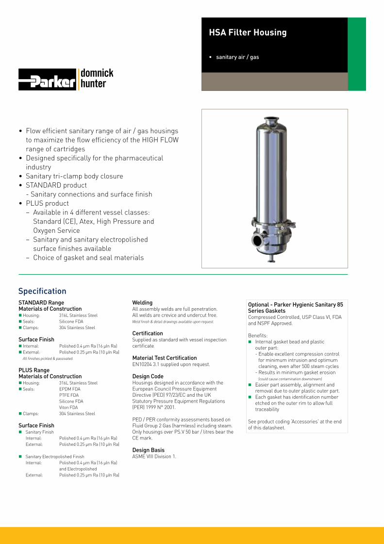
• Flow efficient sanitary range of air / gas housings to maximize the flow efficiency of the HIGH FLOW range of cartridges
• Designed specifically for the pharmaceutical industry
• Sanitary tri-clamp body closure• STANDARD product
- Sanitary connections and surface finish• PLUS product
− Available in 4 different vessel classes: Standard (CE), Atex, High Pressure and Oxygen Service
− Sanitary and sanitary electropolished surface finishes available
− Choice of gasket and seal materials
Specification
HSA Filter Housing
• sanitary air / gas
STANDARD RangeMaterials of Construction Housing: 316L Stainless Steel Seals: Silicone FDA Clamps: 304 Stainless Steel
Surface Finish Internal: Polished 0.4 µm Ra (16 µIn Ra) External: Polished 0.25 µm Ra (10 µIn Ra) All finishes pickled & passivated.
PLUS RangeMaterials of Construction Housing: 316L Stainless Steel Seals: EPDM FDA PTFE FDA Silicone FDA Viton FDA Clamps: 304 Stainless Steel
Surface Finish Sanitary Finish Internal: Polished 0.4 µm Ra (16 µIn Ra) External: Polished 0.25 µm Ra (10 µIn Ra)
Sanitary Electropolished Finish Internal: Polished 0.4 µm Ra (16 µIn Ra) and Electropolished External: Polished 0.25 µm Ra (10 µIn Ra)
WeldingAll assembly welds are full penetration. All welds are crevice and undercut free.Weld finish & detail drawings available upon request.
CertificationSupplied as standard with vessel inspection certificate.
Material Test CertificationEN10204 3.1 supplied upon request.
Design CodeHousings designed in accordance with the European Council Pressure Equipment Directive (PED) 97/23/EC and the UK Statutory Pressure Equipment Regulations (PER) 1999 N° 2001.
PED / PER conformity assessments based on Fluid Group 2 Gas (harmless) including steam. Only housings over PS.V 50 bar / litres bear the CE mark. Design BasisASME VIII Division 1.
Optional - Parker Hygienic Sanitary 85 Series GasketsCompressed Controlled, USP Class VI, FDA and NSPF Approved.
Benefits: Internal gasket bead and plastic outer part: - Enable excellent compression control for minimum intrusion and optimum cleaning, even after 500 steam cycles - Results in minimum gasket erosion (could cause contamination downstream)
Easier part assembly, alignment and removal due to outer plastic outer part. Each gasket has identification number etched on the outer rim to allow full traceability
See product coding ‘Accessories’ at the end of this datasheet.

HSA Filter Housings
Standard Range
Working Condition PED 97/23/EC
Non Dangerous
Dangerous
Fluid Group State Temperature
Gas / Vapour
Gas / Vapour
150 °C (302 °F)
150 °C (302 °F)
PED Conformity Assessment Category
Volume (litres)
01A 01B 01K 011 012
Maximum Pressure
10.00 barg 10.00 barg 10.00 barg 10.00 barg 10.00 barg (145.03 psig) (145.03 psig) (145.03 psig) (145.03 psig) (145.03 psig)
10.00 barg 10.00 barg 8.00 barg 8.00 barg 8.00 barg (145.03 psig) (145.03 psig) (116.03 psig) (116.03 psig) (116.03 psig)
SEP SEP SEP SEP SEP
0.75 0.5 1.9 3.1 5.0
Plus Range
ATEX Working Condition PED 97/23/EC
Non Dangerous
Dangerous
Fluid Group State Temperature
Gas / Vapour
Gas / Vapour
135 °C (275 °F)
135 °C (275 °F)
PED Conformity Assessment Category
Volume (litres)
CE Working Condition PED 97/23/EC
Non Dangerous
Dangerous
Fluid Group State Temperature
Gas / Vapour
Gas / Vapour
150 °C (302 °F)
150 °C (302 °F)
PED Conformity Assessment Category
Volume (litres)
High Pressure Working Condition PED 97/23/EC
Non Dangerous
Fluid Group State Temperature
Gas / Vapour 205 °C (401 °F)
PED Conformity Assessment Category
Volume (litres)
Oxygen Service Working Condition PED 97/23/EC
Dangerous
Fluid Group State Temperature
Gas / Vapour 150 °C (302 °F)
PED Conformity Assessment Category
Volume (litres)
01A 01B 01K 011 012 013 014
Maximum Pressure
10.00 barg 10.00 barg 10.00 barg 10.00 barg 10.00 barg 10.00 barg 10.00 barg (145.03 psig) (145.03 psig) (145.03 psig) (145.03 psig) (145.03 psig) (145.03 psig) (145.03 psig)
8.00 barg 8.00 barg 8.00 barg 8.00 barg 8.00 barg 7.20 barg 5.60 barg (116.03 psig) (116.03 psig) (116.03 psig) (116.03 psig) (116.03 psig) (104.42 psig) (81.22 psig)
SEP SEP SEP CAT I CAT I CAT I CAT I
0.75 0.5 1.9 3.1 5.0 6.9 8.8
01A 01B 01K 011 012 013 014
Maximum Pressure
10.00 barg 10.00 barg 10.00 barg 10.00 barg 10.00 barg 10.00 barg 10.00 barg (145.03 psig) (145.03 psig) (145.03 psig) (145.03 psig) (145.03 psig) (145.03 psig) (145.03 psig)
10.00 barg 10.00 barg 8.00 barg 8.00 barg 8.00 barg 7.20 barg 5.60 barg (145.03 psig) (145.03 psig) (116.03 psig) (116.03 psig) (116.03 psig) (104.42 psig) (81.22 psig)
SEP SEP SEP SEP CAT I CAT I CAT I
0.75 0.5 1.9 3.1 5.0 6.9 8.8
01A 01B 01K 011 012 013 014
Maximum Pressure
16.00 barg 16.00 barg 16.00 barg 16.00 barg 16.00 barg 16.00 barg 16.00 barg (232.06 psig) (232.06 psig) (232.06 psig) (232.06 psig) (232.06 psig) (232.06 psig) (232.06 psig)
SEP SEP SEP SEP CAT I CAT I CAT I
0.75 0.5 1.9 3.1 5.0 6.9 8.8
01A 01B 01K 011 012 013 014
Maximum Pressure
10.00 barg 10.00 barg 8.00 barg 8.00 barg 8.00 barg 7.20 barg 5.60 barg (145.03 psig) (145.03 psig) (116.03 psig) (116.03 psig) (116.03 psig) (104.42 psig) (81.22 psig)
SEP SEP SEP SEP CAT I CAT I CAT I
0.75 0.5 1.9 3.1 5.0 6.9 8.8
Note: All housings are fully vacuum rated.

HSA Filter Housing and Cartridge Performance
barg 1 2 3 4 5 6 7 8 9 10 11 12 13 14 15 16
Flow Correction Factors
15 29 44 58 73 87 100 116 131 145 160 174 189 203 218 232
0.4 0.5 0.65 0.75 0.85 0.95 1 1.15 1.25 1.40 1.50 1.60 1.75 1.90 2.00 2.15
psig
Correction Factor
LinePressure
Membrane FiltersHIGH FLOW TETPOR IIFood and Beverage sterile air / particulate free filtration
Sterile Air / ISO 8573.1:2001 - Class 1 Particulate Removal
Full retention of bacteria, viruses and particulate. Based on membrane technology. Retention correlated to a liquid bacterial challenge (ASTM 383-05) as well as bacterial and viral aerosol challenge. Used for the most critical of applications including medical, pharmaceutical / aseptic packaging and electronics.
Depth FiltersHIGH FLOW BIO-XProven depth filter technology and pleated construction to provide retention down to0.01 micron in gas.
10¨ Size (250 mm) Cartridge2¨ Line Size Housing
600
500
400
300
200
100
0
Diff
eren
tial
Pre
ssur
e (m
bar)
8
7
6
5
4
3
2
1
0
Diff
eren
tial
Pre
ssur
e (p
si)
0 100 200 300 400 500 600 700
Flow (Nm3 / hr) (air @ 21 °C)
Flow rates for other sizes available upon request
A Size (125 mm) Cartridge1¨ Lines Size Housing
200
150
100
50
0
Diff
eren
tial
Pre
ssur
e (m
bar)
1.5
1.0
0.5
0
Diff
eren
tial
Pre
ssur
e (p
si)
0 10 20 30 40 50 60 70 80 90
Flow (Nm3 / hr) (air @ 21 °C)
Flow rates for other sizes available upon request
0 barg
2 barg
0 barg
2 barg
10¨ Size (250 mm) Cartridge2¨ Line Size Housing
1000
900
800
700
600
500
400
300
200
100
0
Diff
eren
tial
Pre
ssur
e (m
bar)
14
12
10
8
6
4
2
0
Diff
eren
tial
Pre
ssur
e (p
si)
0 100 200 300 400 500 600 700
Flow (Nm3 / hr) (air @ 21 °C)
Flow rates for other sizes available upon request
A Size (125 mm) Cartridge1¨ Line Size Housing
700
600
500
400
300
200
100
0
Diff
eren
tial
Pre
ssur
e (m
bar)
10
9
8
7
6
5
4
3
2
1
0
Diff
eren
tial
Pre
ssur
e (p
si)
0 20 40 60 80 100 120 140 160 180
Flow (Nm3 / hr) (air @ 21 °C)
Flow rates for other sizes available upon request
2 barg
0 barg
0 barg
2 barg

HSA Filter Housings
Dim ‘A’
Dim ‘B’
Dim ‘C’Bowl Removal Height
Gauge Port11/2¨ Tri-Clamp
Bowl
Body Clamp
Tri-ClampBody Seal
Head
Outlet Port
Drain Port1/2¨ Tri-Clamp
Inlet / Outlet Port1¨ Tri-Clamp
The PLUS product range is available with many options of connections, vents, drains, surface finish, seals classification, etc. Please see product coding.
Physical Characteristics
Bowl Height
Dimensions shown are based on the STANDARD range. For accurate dimensions, please contact Parker domnick hunter.
A Size 125 mm (5¨)
B Size 65 mm (21/2¨)
125 mm (5¨)
250 mm (10¨)
500 mm (20¨)
152 mm (6.0¨) 227 mm (9.0¨) 130 mm (5.1¨)
152 mm (6.0¨) 172 mm (6.8¨) 70 mm (2.8¨)
157 mm (6.2¨) 337 mm (13.3¨) 194 mm (7.6¨)
157 mm (6.2¨) 487 mm (19.2¨) 313 mm (12.3¨)
157 mm (6.2¨) 737 mm (29.0¨) 561 mm (22.1¨)
1.3 Kg (2.86 lbs)
1.2 Kg (2.64 lbs)
5.1 Kg (11.22 lbs)
5.7 Kg (12.54 lbs)
6.7 Kg (14.74 lbs)
Dimensions ‘A’ ‘B’ ‘C’ Typical Weight
Example: Showing Demi A Size with 1¨ connections

STANDARD Range - K to 20¨
HSA -
Code ǀ Length (Nominal)
K 5¨ (125 mm)1 10¨ (250 mm)2 20¨ (500 mm)
Code ǀ Connection Size
Y 11/2¨ (38.1 mm)
Code ǀ Cartridge
C 226
HSA Filter Housings
Code ǀ Vessel Class
CE Standard
Code ǀ Standard
T Tri-Clamp
Code ǀ Seal
S Silicone
-01
DS_HS_47_10/12_2B
STANDARD Range - Demi A & B
HSA -
Code ǀ Length (Nominal)
A 5¨ (125 mm)B 21/2¨ (65 mm)
Code ǀ Connection Size
B 1¨
Code ǀ Cartridge
T 126
Code ǀ Vessel Class
CE Standard
Code ǀ Standard
T Tri-Clamp
Code ǀ Seal
S Silicone
-01
PLUS Range - K to 40¨
HSA
Code ǀ Length (Nominal)
K 5¨ (125 mm)1 10¨ (250 mm)2 20¨ (500 mm)
Code ǀ Connection Size
Y 11/2¨ (38.1 mm)
Code ǀ Cartridge
C 226
Code ǀ Vessel Class
CE StandardHP* High Pressure
Code ǀ Standard
T Tri-Clamp
Code ǀ Seal
E EPDMP* PTFES SiliconeV Viton
01
Code ǀ Vent
T 11/2¨ TCF Only
Code ǀ Drain
T 1/2¨ TCF
Code ǀ Surface Finish Internal External
B Sanitary 0.4 µm 0.25 µm Code ǀ Tagged
X No
- - -
For Tagged Options customer identification numbers required at time of ordering
* Double bolted clamp required
* Supplied complete with a double bolted clamp
PLUS Range - Demi A & B
HSA
Code ǀ Length (Nominal)
A 5¨ (125 mm)B 21/2¨ (65 mm)
Code ǀ Connection Size
B 1¨
Code ǀ Cartridge
T 126
Code ǀ Vessel Class
CE StandardHP* High Pressure
Code ǀ Standard
T Tri-Clamp
Code ǀ Seal
E EPDMP* PTFES SiliconeV Viton
01
Code ǀ Vent
T 11/2¨ TCF Only
Code ǀ Drain
T 1/2¨ TCF
Code ǀ Surface Finish Internal External
B Sanitary 0.4 µm 0.25 µm
Code ǀ Tagged
X No
- - -
For Tagged Options customer identification numbers required at time of ordering
* Double bolted clamp required
Parker domnick hunter has a continuous policy of product development and although the Company reserves the right to change specifications, it attempts to keep customers informed of any alterations. This publication is for general information only and customers are requested to contact our Process Filtration Sales Department for detailed information and advice on a products suitability for specific applications. All products are sold subject to the company’s Standard conditions of sale.
* Supplied complete with a double bolted clamp
Code ǀ Main Spare Parts Kits
XTCSS08SA Demi 2.5¨ clamp Standard 10 barg - single pinXTCSS08TC Demi 2.5¨ clamp HP high pressure - double boltXTCSS10SL Demi 4¨ clamp Standard 10 barg - single pinXTCSS10HP15 Demi 4¨ clamp HP high pressure - double boltXPGSS06TC4 Sanitary gauge 1.5¨ Tri-Clamp (ISO2852) connection 10 bargXVASS04TC6 Diaphragm drain valve 1/2¨ Tri-Clamp - silicone
For further information on these and other spares and accessories, please request datasheets.
Code | Demi Range
XGKEP08NA 2.5¨ Tri-Gasket EPDMXGKSI08 2.5¨ Tri-Gasket SiliconeXGKVI08SA 2.5¨ Tri-Gasket FKMXGKPT10SA 2.5¨ Tri-Gasket PTFEXGKPT08SA 2.5¨ Tri-Gasket PTFE TUF-FLEX
For further information on Parker hygienic gaskets for TUF-FLEX gaskets, please request datasheets.
Code | K - 40¨ Range
XTSEP10IL 4¨ Tri-Gasket EPDMXTSSI10SL 4¨ Tri-Gasket SiliconeXTSVI10SL 4¨ Tri-Gasket FKMXTSPT10SL 4¨ Tri-Gasket PTFEXGKPT10SA1 4¨ Tri-Gasket PTFE TUF-FLEX
Accessories (Other accessories available upon request)
85 Series Parker Hygienic Seals
Type B design, over moulded rubber to plastic clip design.
85
Code ǀ Rubber Material
1 Silicone / Rust2 FKM / Black3 EPDM / White4 Nitrile / Black5 Silicone / Clear6 EPDM / Black
Code ǀ Diameter
16 1¨24 1.5¨32 2¨40 2.5¨48 3¨64 4¨
-
Code ǀ Plastic Material
B BlueR Red
-
Standard Housing Gaskets - Kits (Qty = 1)
AT ATEXOX Oxygen Service 3 30¨ (750 mm)
4 40¨ (1000 mm)
C 2¨ (50.8 mm) C Rectus 21 VerticalH 11/2¨ TCF & HosebarbI 11/2¨ TCF & Staubli RBE03M 11/2¨ TCF & 1/2¨ TCFR 11/2¨ TCF & Rectus 21S Staubli RBE03 Vertical
H HosebarbR Rectus 21S Staubli RBE03
P Sanitary Electropolished 0.4 µm EP 0.25 µm
T Yes
T 3/4¨A 1/2¨AT ATEX
OX Oxygen Service
C Rectus 21 VerticalH 11/2¨ TCF & HosebarbI 11/2¨ TCF & Staubli RBE03M 11/2¨ TCF & 1/2¨ TCFR 11/2¨ TCF & Rectus 21S Staubli RBE03 Vertical
H HosebarbR Rectus 21S Staubli RBE03
P Sanitary Electropolished 0.4 µm EP 0.25 µm
T Yes
Delivery KeyStandarddelivery times
PLUSdelivery times
Euro
pe:
+44
(0)1
91 4
1051
21
dhp
roce
ss@
park
er.c
om -
Nor
th A
mer
ica:
✆ +
1 60
8 82
4 05
00
dhp
sale
s.na
@pa
rker
.com
w
ww.
park
er.c
om/d
hpha
rma

Specification
Demi HSA⊕ Z StyleFilter Housing• sanitary air / gas
Materials of Construction Housing: 316L Stainless Steel Body Seal: EPDM FDA PTFE FDA Silicone FDA Viton FDA Vent / Drain Seal: PTFE FDA
Surface Finish Options Sanitary Internal: Polished 0.4 µm Ra (16 µIn Ra) External: Polished 0.25 µm Ra (10 µIn Ra) Sanitary Electropolished Internal: Polished 0.4 µm Ra (16 µIn Ra) and Electropolished External: Polished 0.25 µm Ra (10 µIn Ra)
WeldingAll assembly welds are full penetration. All welds are crevice and undercut free.Weld finish & detail drawings available upon request.
Design CodeHousings designed in accordance with the European Council Pressure Equipment Directive (PED) 97/23/EC and the UK Statutory Pressure Equipment Regulations (PER) 1999 N° 2001.
Design BasisASME VIII Division 1.ATEX 94/9/EC (where applicable)
• Flow efficient range of air / gas housings
• Available in 4 different housing classes: Standard (CE), Atex, High Pressure & Oxygen Service
• Sanitary and sanitary electropolished surface finishes available
• A choice of connections, vents, drains, gaskets & surface finishes
• Parker domnick hunter ‘Z’ location
(PLUS product only - no STANDARD range)
ATEX Working Condition PED 97/23/EC
Non Dangerous &Dangerous
Fluid Group State Temperature 01A 01B
Maximum Pressure
Gas / Vapour 135 °C (275 °F) 10.00 barg 10.00 barg (145.03 psig) (145.03 psig)
PED Conformity Assessment Category SEP SEP
Volume (litres) 0.75 0.50
CE Working Condition PED 97/23/EC
Non Dangerous & Dangerous
Fluid Group State Temperature 01A 01B
Maximum Pressure
Gas / Vapour 150 °C (302 °F) 10.00 barg 10.00 barg (145.03 psig) (145.03 psig)
PED Conformity Assessment Category SEP SEP
Volume (litres) 0.75 0.50
High Pressure Working Condition PED 97/23/EC
Non Dangerous
Fluid Group State Temperature 01A 01B
Maximum Pressure
Gas / Vapour 205 °C (401 °F) 16.00 barg 16.00 barg (232.06 psig) (232.06 psig)
PED Conformity Assessment Category SEP SEP
Volume (litres) 0.75 0.50
Oxygen Service Working Condition PED 97/23/EC
Dangerous
Fluid Group State Temperature 01A 01B
Maximum Pressure
Gas / Vapour 150 °C (302 °F) 10.00 barg 10.00 barg (145.03 psig) (145.03 psig)
PED Conformity Assessment Category SEP SEP
Volume (litres) 0.75 0.50
Note: All housings are fully vacuum rated.

Physical Characteristics
Demi HSA⊕ Z Style Filter Housings
Vent Port
Bowl
Body ClampDouble bolted clamp required for PTFEseal or HP version
Body Seal
Head
Inlet Port
Dim ‘A’
Dim ‘B’
Dim ‘C’Bowl Removal Height
Drain Plug
Ordering Information
Vent Plug
Vent Seal
Drain PortDrain Seal
Outlet Port
HSA
Code ǀ Length (Nominal)
A 5¨ (125 mm)B 21/2¨ (65 mm)
Code ǀ Connection Size
B 1¨
Code ǀ Cartridge
Z 116
Code ǀ Vessel Class
CE StandardAT ATEXHP High PressureOX Oxygen Service
Code ǀ Standard
B BSPP (F)N NPT (F)T Tri-ClampW ISO / BS Pipe
Code ǀ Seal
E EPDMP* PTFES SiliconeV Viton
01
Code ǀ Vent
B 1/4¨ BSPP (F)N 1/4¨ NPT (F)
Code ǀ Drain
B 1/4¨ BSPPN 1/4¨ NPT
Code ǀ Surface Finish Internal External
B Sanitary 0.4 µm 0.25 µmP Sanitary Electropolished 0.4 µm EP 0.25 µm
Code ǀ Tagged
T YesX No
- - -
For Tagged Options customer identification numbers required at time of ordering
Bowl Dimensions (mm) Typical Height ‘A’ ‘B’ ‘C’ Weight Weld Tri-Clamp BSP/NPT (KG)
A Size 5¨ (125 mm) 106 149 172 295 177 1.5
B Size 21/2¨ (65 mm) 106 149 172 240 122 1.4
Dimensions are based on illustration shown.For accurate dimensions, please contact Parker domnick hunter.
* Double bolted clamp required
DS_HS_38_01/11_2AParker domnick hunter has a continuous policy of product development and although the Company reserves the right to change specifications, it attempts to keep customers informed of any alterations. This publication is for general information only and customers are requested to contact our Process Filtration Sales Department for detailed information and advice on a products suitability for specific applications. All products are sold subject to the company’s Standard conditions of sale.
Euro
pe:
+44
(0)1
91 4
1051
21
dhp
roce
ss@
park
er.c
om -
Nor
th A
mer
ica:
✆ +
1 60
8 82
4 05
00
dhp
sale
s.na
@pa
rker
.com
w
ww.
park
er.c
om/d
hpha
rma

Specification
HSV Filter Housings
• vent applications
STANDARD RangeMaterials of Construction Housing: 316L Stainless Steel Seals: Silicone FDA Clamps: 304 Stainless Steel
Surface Finish Internal: As welded External: Polished 0.8 µm (32 µIn Ra) All finishes pickled & passivated.
PLUS RangeMaterials of Construction Housing: 316L Stainless Steel Seals: EPDM FDA PTFE FDA Silicone FDA Viton FDA Note: Seal used only to position bowl clamp arrangement.
Clamps: 304 Stainless Steel
Surface Finish Standard Finish Internal: As Welded Pickled & Passivated External: Polished 0.8 µm Ra (32 µIn Ra) Sanitary Finish Internal: Polished 0.4 µm Ra (16 µIn Ra) External: Polished 0.25 µm Ra (10 µIn Ra) Sanitary Electropolished Finish Internal: Polished 0.4 µm Ra (16 µIn Ra) and Electropolished External: Polished 0.25 µm Ra (10 µIn Ra)
WeldingAll assembly welds are full penetration. All welds are crevice and undercut free.Weld finish & detail drawings available upon request.
CertificationSupplied as standard with vessel inspection certificate.
Material Test CertificationEN10204 3.1 supplied upon request.
Recommended Operation Guidelines SizingSizing vent vessels particulary for vacuum sensitive tanks can require specialist advice. It is important that VENT housings are sized on maximum gas flow capacity under actual operation conditions. Vacuum ProtectionWhere a tank is vacuum sensitive, there is a risk of tank collapse. In such cases the fitting of an appropriately rated bursting disc (or similar) and, if necessary a pressure relief valve, is highly recommended.
• Direct connection to tank boss allows housing to be self-supportive
• Easy assembly and maintenance• STANDARD product
- Standard surface finish & tri-clamp connection• PLUS product
− Available as STANDARD or for Atex applications − Standard, sanitary and sanitary electropolished
surface finishes available − Connection choices
(Also see HSVLP (L-Port) Datasheet)

HSV Filter Housings
The PLUS product range is available with many options of connections, vents, drains, surface finish, seals classification, etc. Please see product coding.
Physical Characteristics
Bowl Height
A Size 125 mm (5¨)
B Size 65 mm (21/2¨)
125 mm (5¨)
250 mm (10¨)
500 mm (20¨)
750 mm (30¨)
1000 mm (40¨)
75 mm (2.9¨) 195 mm (7.7¨) 130 mm (5.1¨)
75 mm (2.9¨) 140 mm (5.5¨) 70 mm (2.8¨)
132 mm (5.2¨) 242 mm (9.5¨) 194 mm (7.6¨)
132 mm (5.2¨) 392 mm (15.4¨) 313 mm (12.3¨)
132 mm (5.2¨) 642 mm (25.3¨) 561 mm (22.1¨)
132 mm (5.2¨) 890 mm (35.0¨) 809 mm (31.8¨)
132 mm (5.2¨) 1138 mm (44.8¨) 1057 mm (41.6¨)
1.0 Kg (2.2lbs)
0.9 Kg (1.9lbs)
2.2 Kg (4.8 lbs)
2.8 Kg (6.1 lbs)
3.8 Kg (8.3 lbs)
4.8 Kg (10.6 lbs)
5.8 Kg (12.8 lbs)
Dimensions (mm) ‘A’ ‘B’ ‘C’ Typical Weight
Example: Showing Demi A Size with 1¨ connections
Bowl
Body Clamp
Body Seal
Head
Dim ‘A’
Dim ‘B’
Dim ‘C’Bowl Removal Height
Dimensions shown are based on the STANDARD range. For accurate dimensions, please contact Parker domnick hunter.
Note: All housings are fully vacuum rated.

HSV Filter Housings
Parker domnick hunter has a continuous policy of product development and although the Company reserves the right to change specifications, it attempts to keep customers informed of any alterations. This publication is for general information only and customers are requested to contact our Process Filtration Sales Department for detailed information and advice on a products suitability for specific applications. All products are sold subject to the company’s Standard conditions of sale.
STANDARD Range - K to 20¨
HSV -
Code ǀ Length (Nominal)
K 5¨ (125 mm)1 10¨ (250 mm)2 20¨ (500 mm)
Code ǀ Connection Size
Y 11/2¨ (38.1 mm)
Code ǀ Cartridge
C 226
Code ǀ Vessel Class
DH Vent Housing
Code ǀ Standard
T Tri-Clamp
Code ǀ Seal
S Silicone
-01
STANDARD Range - Demi A & B
HSV -
Code ǀ Length (Nominal)
A 5¨ (125 mm)B 21/2¨ (65 mm)
Code ǀ Connection Size
B 1¨ (25.4 mm)
Code ǀ Cartridge
T 126
Code ǀ Vessel Class
DH Vent Housing
Code ǀ Standard
T Tri-Clamp
Code ǀ Seal
S Silicone
-01
PLUS Range - K to 40¨
HSV
Code ǀ Length (Nominal)
K 5¨ (125 mm)1 10¨ (250 mm)2 20¨ (500 mm)3 30¨ (750 mm)4 40¨ (1000 mm)
Code ǀ Connection Size
C 2¨ (50.8 mm)Y 11/2¨ (38.1 mm)
Code ǀ Cartridge
C 226
Code ǀ Vessel Class
DH StandardAT ATEX
Code ǀ Standard
B BSPP (F)D DIN11851(M)F ANSI RF150L BS4504 DIN2633N NPT (F)T Tri-ClampW BS / ISO Pipe
Code ǀ Seal
E EPDMP PTFES SiliconeV Viton
01
Code ǀ Surface Finish Internal External
B Sanitary 0.4 µm 0.25 µmI Standard As Welded 0.8 µmP Sanitary Electropolished 0.4 µm EP 0.25 µm
Code ǀ Tagged
T YesX No
- -
For Tagged Options customer identification numbers required at time of ordering
PLUS Range - Demi A & B
HSV
Code ǀ Length (Nominal)
A 5¨ (125 mm)B 21/2¨ (65 mm)
Code ǀ Connection Size
B 1¨ (25.4 mm)
Code ǀ Cartridge
T 126
Code ǀ Vessel Class
DH StandardAT ATEX
Code ǀ Standard
B BSPP (F)D DIN11851F ANSI RF150L BS4504 DIN2633N NPT (F)T Tri-Clamp
Code ǀ Seal
E EPDMP PTFES SiliconeV Viton
01
Code ǀ Surface Finish Internal External
B Sanitary 0.4 µm 0.25 µmI Standard As Welded 0.8 µmP Sanitary Electropolished 0.4 µm EP 0.25 µm
Code ǀ Tagged
T YesX No
- -
For Tagged Options customer identification numbers required at time of ordering
DS_HS_49_01/11_2A
Euro
pe:
+44
(0)1
91 4
1051
21
dhp
roce
ss@
park
er.c
om -
Nor
th A
mer
ica:
✆ +
1 60
8 82
4 05
00
dhp
sale
s.na
@pa
rker
.com
w
ww.
park
er.c
om/d
hpha
rma

Specification
HSVLP Filter Housings
• L configuration vent
Materials of Construction Housing: 316L Stainless Steel Seals: EPDM FDA PTFE FDA Silicone FDA Viton FDA Note: Seal used only to position bowl clamp arrangement.
Clamps: 304 Stainless Steel
Surface Finish Standard Finish Internal: As Welded Pickled & Passivated External: Polished 0.8 µm Ra (32 µIn Ra) Sanitary Finish Internal: Polished 0.4 µm Ra (16 µIn Ra) External: Polished 0.25 µm Ra (10 µIn Ra) Sanitary Electropolished Finish Internal: Polished 0.4 µm Ra (16 µIn Ra) and Electropolished External: Polished 0.25 µm Ra (10 µIn Ra)
WeldingAll assembly welds are full penetration. All welds are crevice and undercut free.Weld finish & detail drawings available upon request.
• Sanitary vent housing - L Port configuration
• Tri-clamp or weld end connection
• Standard, sanitary and sanitary electropolished surface finishes available
•Wide range of vents and drains
• Choice of gasket and seal materials
Working Condition PED 97/23/EC
Standard
Fluid Group State Temperature
Gas / Vapour 150 °C (302 °F)
Volume (litres)
01K 011 012 013 014
Maximum Pressure
10.00 barg 10.00 barg 10.00 barg 10.00 barg 10.00 barg (145.03 psig) (145.03 psig) (145.03 psig) (145.03 psig) (145.03 psig)
1.6 2.8 4.7 6.6 8.5
Note: All housings are fully vacuum rated.

HSVLP Filter Housings
Physical Characteristics
Bowl Height
Dimensions shown are based on the STANDARD range. For accurate dimensions, please contact Parker domnick hunter.
125 mm (5¨)
250 mm (10¨)
500 mm (20¨)
750 mm (30¨)
1000 mm (40¨)
190 mm (7.5¨) 213 mm (8.4¨) 216 mm (8.5¨)
340 mm (13.4¨) 363 mm (14.3¨) 366 mm (14.4¨)
590 mm (23.2¨) 613 mm (24.1¨) 616 mm (24.3¨)
835 mm (32.9¨) 858 mm (33.8¨) 861 mm (33.9¨)
1085 mm (42.7¨) 1108 mm (43.6¨) 1111 mm (53.7¨)
3.3 Kg (7.3 lbs)
3.9 Kg (8.6 lbs)
4.9 Kg (10.8 lbs)
5.9 Kg (13.0 lbs)
6.9 Kg (15.2 lbs)
Dimensions (mm) ‘A’ ‘B’ ‘C’ Typical Weight
Dim ‘A’ - No VentDim ‘B’ - 1/2¨ Tri-ClampDim ‘C’ - Staubli / Rectus Socket
54 m
m
Weld - 174 mmTri-Clamp - 137 mm
Bowl
Body Clamp
Body Seal
Head
Outlet Port
Sample Port
Sample Port
Double bolted clamp required with PTFE seal
DS_HS_45_01/11_2A
Ordering Information
HSVLP
Code ǀ Length (Nominal)
K 5¨ (125 mm)1 10¨ (250 mm)2 20¨ (500 mm)3 30¨ (750 mm)4 40¨ (1000 mm)
Code ǀ Connection Size
Y 11/2¨ (38.1 mm)
Code ǀ Cartridge
C 226
Code ǀ Standard
T Tri-ClampW BS / ISO Pipe
Code ǀ Seal
E EPDMP* PTFES SiliconeV Viton
01
Code ǀ Vent
H 11/2 ̈TCF & HosebarbR 11/2 ̈TCF & Rectus 21S Staubli RBE03 VerticalT 11/2 ̈TCF OnlyX No Vent
Code ǀ Drain
H Hosebarb InletR Rectus 21 InletS Staubli RBE03T 1/2¨ Tri-Clamp InletX No Drain
Code ǀ Surface Finish Internal External
B Sanitary 0.4 µm 0.25 µmI Standard As Welded 0.8 µmP Sanitary Electropolished 0.4 µm EP 0.25 µm Code ǀ Tagged
T YesX No
- - -
For Tagged Options customer identification numbers required at time of ordering
*Double bolted clamp must be used with PTFE seal
Parker domnick hunter has a continuous policy of product development and although the Company reserves the right to change specifications, it attempts to keep customers informed of any alterations. This publication is for general information only and customers are requested to contact our Process Filtration Sales Department for detailed information and advice on a products suitability for specific applications. All products are sold subject to the company’s Standard conditions of sale.
Euro
pe:
+44
(0)1
91 4
1051
21
dhp
roce
ss@
park
er.c
om -
Nor
th A
mer
ica:
✆ +
1 60
8 82
4 05
00
dhp
sale
s.na
@pa
rker
.com
w
ww.
park
er.c
om/d
hpha
rma

Specification
HSL Filter Housings
• sanitary liquid
STANDARD RangeMaterials of Construction Housing: 316L Stainless Steel Seals: Silicone FDA Clamps: 304 Stainless Steel
Surface Finish Internal: Polished 0.4 µm Ra (16 µIn Ra) External: Polished 0.25 µm Ra (10 µIn Ra) All finishes pickled & passivated.
PLUS RangeMaterials of Construction Housing: 316L Stainless Steel Seals: EPDM FDA PTFE FDA Silicone FDA Viton FDA Clamps: 304 Stainless Steel
Surface Finish Sanitary Finish Internal: Polished 0.4 µm Ra (16 µIn Ra) External: Polished 0.25 µm Ra (10 µIn Ra)
Sanitary Electropolished Finish Internal: Polished 0.4 µm Ra (16 µIn Ra) and Electropolished External: Polished 0.25 µm Ra (10 µIn Ra)
WeldingAll assembly welds are full penetration. All welds are crevice and undercut free.Weld finish & detail drawings available upon request.
CertificationSupplied as standard with vessel inspection certificate.
Material Test CertificationEN10204 3.1 supplied upon request.
Design CodeHousings designed in accordance with the European Council Pressure Equipment Directive (PED) 97/23/EC and the UK statutory Pressure Equipment Regulations (PER) 1999 N° 2001.
PED / PER conformity assessments based on Fluid Group 2 Gas (harmless) including steam. Only housings over PS.V 50 bar / litres bear the CE mark. Design BasisASME VIII Division 1.
• Single element sanitary liquid housing• Designed specifically for the food &
beverage and pharmaceutical industries• Sanitary tri-clamp body closure as standard• STANDARD product
− Sanitary surface finish − Tri-clamp connections
• PLUS product − Available in 3 different vessel classes:
Standard (CE), Atex and High Pressure − Sanitary or sanitary electropolished
surface finish options − Wide range of vent and drain connections − Choice of gasket and seal materials

HSL Filter Housings
Standard Range
Working Condition PED 97/23/EC
Non Dangerous
Dangerous
Fluid Group State Temperature
Liquid / Gas
Liquid / Gas
150 °C (302 °F)
150 °C (302 °F)
PED Conformity Assessment Category
Volume (litres)
01A 01B 011 012 013
Maximum Pressure
10.00 barg 10.00 barg 10.00 barg 10.00 barg 10.00 barg (145.03 psig) (145.03 psig) (145.03 psig) (145.03 psig) (145.03 psig)
10.00 barg 10.00 barg 5.00 barg 5.00 barg 5.00 barg (145.03 psig) (145.03 psig) (72.51 psig) (72.51 psig) (72.51 psig)
SEP SEP SEP SEP CAT I
0.75 0.5 2.9 4.8 6.7
Plus Range
High Pressure Working Condition PED 97/23/EC
Non Dangerous
Fluid Group State Temperature
Gas / Vapour / Liquid 205 °C (401 °F)
PED Conformity Assessment Category
Volume (litres)
01A 01B 01K 011 012 013 014
Maximum Pressure
16.00 barg 16.00 barg 16.00 barg 16.00 barg 16.00 barg 16.00 barg 16.00 barg (232.06 psig) (232.06 psig) (232.06 psig) (232.06 psig) (232.06 psig) (232.06 psig) (232.06 psig)
SEP SEP SEP SEP CAT I CAT I CAT I
0.75 0.5 1.7 2.9 4.8 6.7 8.6
ATEX Working Condition PED 97/23/EC
Non Dangerous
Dangerous
Non Dangerous
Dangerous
Fluid Group State Temperature
Gas / Vapour
Gas / Vapour
Liquid
Liquid
135 °C (275 °F)
135 °C (275 °F)
135 °C (275 °F)
135 °C (275 °F)
PED Conformity Assessment Category
Volume (litres)
01A 01B 01K 011 012 013 014
Maximum Pressure
10.00 barg 10.00 barg 10.00 barg 10.00 barg 10.00 barg 10.00 barg 10.00 barg (145.03 psig) (145.03 psig) (145.03 psig) (145.03 psig) (145.03 psig) (145.03 psig) (145.03 psig)
10.00 barg 10.00 barg 5.00 barg 5.00 barg 5.00 barg 5.00 barg 5.00 barg (145.03 psig) (145.03 psig) (72.51 psig) (72.51 psig) (72.51 psig) (72.51 psig) (72.51 psig)
SEP SEP SEP SEP SEP CAT I CAT I
0.75 0.5 1.7 2.9 4.8 6.7 8.6
CE Working Condition PED 97/23/EC
Non Dangerous
Dangerous
Non Dangerous
Dangerous
Fluid Group State Temperature
Gas / Vapour
Gas / Vapour
Liquid
Liquid
150 °C (302 °F)
150 °C (302 °F)
150 °C (302 °F)
150 °C (302 °F)
PED Conformity Assessment Category
Volume (litres)
01A 01B 01K 011 012 013 014
Maximum Pressure
10.00 barg 10.00 barg 10.00 barg 10.00 barg 10.00 barg 10.00 barg 10.00 barg (145.03 psig) (145.03 psig) (145.03 psig) (145.03 psig) (145.03 psig) (145.03 psig) (145.03 psig)
10.00 barg 10.00 barg 5.00 barg 5.00 barg 5.00 barg 5.00 barg 5.00 barg (145.03 psig) (145.03 psig) (72.51 psig) (72.51 psig) (72.51 psig) (72.51 psig) (72.51 psig)
10.00 barg 10.00 barg 10.00 barg 10.00 barg 10.00 barg 10.00 barg 10.00 barg (145.03 psig) (145.03 psig) (145.03 psig) (145.03 psig) (145.03 psig) (145.03 psig) (145.03 psig)
10.00 barg 10.00 barg 5.00 barg 5.00 barg 5.00 barg 5.00 barg 5.00 barg (145.03 psig) (145.03 psig) (72.51 psig) (72.51 psig) (72.51 psig) (72.51 psig) (72.51 psig)
SEP SEP SEP SEP SEP CAT I CAT I
0.75 0.5 1.7 2.9 4.8 6.7 8.6
Note: All housings are fully vacuum rated.

HSL Filter Housings
Physical Characteristics
Bowl Height
A Size 125 mm (5¨)
B Size 65 mm (21/2¨)
250 mm (10¨)
500 mm (20¨)
750 mm (30¨)
1000 mm (40¨)
117 mm (4.6¨) 191 mm (7.5¨) 130 mm (5.1¨)
117 mm (4.6¨) 136 mm (5.4¨) 70 mm (2.8¨)
156 mm (6.1¨) 417 mm (16.4¨) 313 mm (12.3¨)
156 mm (6.1¨) 667 mm (26.3¨) 561 mm (22.1¨)
156 mm (6.1¨) 912 mm (35.9¨) 809 mm (31.8¨)
156 mm (6.1¨) 1160 mm (45.7¨) 1057 mm (41.6¨)
2.0 Kg (4.4lbs)
1.8 Kg (3.9lbs)
3.8 Kg (8.3 lbs)
4.8 Kg (10.5 lbs)
5.7 Kg (12.5 lbs)
6.7 Kg (14.7 lbs)
Dimensions (mm) ‘A’ ‘B’ ‘C’ Typical Weight
Dim ‘A’
Dim ‘B’
Dim ‘C’Bowl Removal Height
The PLUS product range is available with many options of connections, vents, drains, surface finish, seals classification, etc. Please see product coding.
Vent / Gauge Port11/2¨ Tri-Clamp
Bowl
Body Clamp
Body Seal
Head
Drain Port1/2¨ Tri-Clamp
Inlet Port1¨ Tri-Clamp
Inlet Port1¨ Tri-Clamp
Dimensions shown are based on the STANDARD range. For accurate dimensions, please contact Parker domnick hunter.
Example: Showing Demi A Size with 1¨ connectionsNote: Demi vessels have 1/2¨ Tri-Clamp inlet drain as standard
K - 30¨ vessels have no drains as standard

HSL Filter Housings
STANDARD Range - 10¨ to 30¨
HSL -
Code ǀ Length (Nominal)
1 10¨ (250 mm)2 20¨ (500 mm)3 30¨ (750 mm)
Code ǀ Connection Size
B 1¨ (25.4 mm)
Code ǀ Cartridge
C 226
Code ǀ Vessel Class
CE Standard
Code ǀ Standard
T Tri-Clamp
Code ǀ Seal
S Silicone
-01
STANDARD Range - Demi A & B
HSL -
Code ǀ Length (Nominal)
A 5¨ (125 mm)B 21/2¨ (65 mm)
Code ǀ Connection Size
B 1¨
Code ǀ Cartridge
T 216
Code ǀ Vessel Class
CE Standard
Code ǀ Standard
T Tri-Clamp
Code ǀ Seal
S Silicone
-01
PLUS Range - K to 40¨HSL
Code ǀ Length (Nominal)
K 5¨ (125 mm)1 10¨ (250 mm)2 20¨ (500 mm)3 30¨ (750 mm)4 40¨ (1000 mm)
Code ǀ Connection Size
B 1¨ (25.4 mm)
Code ǀ Cartridge
C 226
Code ǀ Vessel Class
CE StandardAT ATEXHP* High Pressure
Code ǀ Standard
D DIN11851(M)F (1) (2) ANSI RF 150H (2) ANSI RF 300L (2) BS4504 DIN2633R RJT(M)S SMS Union (M)T Tri-ClampW ISO / BS Pipe
Code ǀ Seal
E EPDMP* PTFES SiliconeV Viton
01
Code ǀ Vent
A 11/2 ̈TCF & 2 x Rectus 21E 11/2 ̈TCF & 2 x Staubli RBE03H 11/2 ̈TCF & HosebarbI 11/2 ̈TCF & Staubli RBE03M 11/2 ̈TCF & 1/2 ̈TCFR 11/2 ̈TCF & Rectus 21S Staubli RBE03 VerticalT 11/2 ̈TCF Only
Code ǀ Drain
H Hosebarb Inlet OnlyR Rectus 21 Inlet OnlyS Staubli RBE03 Inlet OnlyX No DrainY 1¨ TCF Inlet OnlyZ 1¨ TCF Inlet & Outlet
Code ǀ Surface Finish Internal External
B Sanitary 0.4 µm 0.25 µmP Sanitary Electropolished 0.4 µm EP 0.25 µm
Code ǀ Tagged
T YesX No
- - -
For Tagged Options customer identification numbers required at time of ordering
(1) Not suited for High Pressure Vessels. HP Vessels to use ANSI RF 300.(2) Flanged vessels based on 1¨ O.D. pipe but use 3/4¨ or NW20 flanges.
* Double bolted clamp required
* Supplied complete with a double bolted clamp
PLUS Range - Demi A & B
HSL
Code ǀ Length (Nominal)
A 5¨ (125 mm)B 21/2¨ (65 mm)
Code ǀ Connection Size
B 1¨
Code ǀ Cartridge
T 126
Code ǀ Vessel Class
CE StandardAT ATEXHP High Pressure
Code ǀ Standard
D DIN11851F(1) (2) ANSI RF 150H(2) ANSI RF 300L BS4504 DIN2633R RJTS SMS Union (M)T Tri-ClampW ISO / BS Pipe
Code ǀ Seal
E EPDMP* PTFES SiliconeV Viton
01
Code ǀ Vent
A 11/2¨ TCF & 2 x Rectus 21B 11/2¨ TCF & 2 x Staubli RBE03 H 11/2¨ TCF & HosebarbI 11/2¨ TCF & Staubli RBE03M 11/2¨ TCF & 1/2¨ TCFR 11/2¨ TCF & Rectus 21S Staubli RBE03T 11/2¨ TCF Only
Code ǀ Drain
H Hosebarb Inlet OnlyR Rectus 21 Inlet OnlyS Staubli RBE03 Inlet OnlyT 1/2¨ TCF Inlet OnlyX No Drain
Code ǀ Surface Finish Internal External
B Sanitary 0.4 µm 0.25 µmP Sanitary Electropolished 0.4 µm EP 0.25 µm
Code ǀ Tagged
T YesX No
- - -
For Tagged Options customer identification numbers required at time of ordering
(1) Not suited for High Pressure Vessels. HP Vessels to use ANSI RF 300.(2) Only available in 3/4¨.
* Double bolted clamp required
Note: No drain(s) as standard.
Note: 1/2¨ Tri-Clamp inlet drain as standard.
DS_HS_50_12/11_2BParker domnick hunter has a continuous policy of product development and although the Company reserves the right to change specifications, it attempts to keep customers informed of any alterations. This publication is for general information only and customers are requested to contact our Process Filtration Sales Department for detailed information and advice on a products suitability for specific applications. All products are sold subject to the company’s Standard conditions of sale.
Euro
pe:
+44
(0)1
91 4
1051
21
dhp
roce
ss@
park
er.c
om -
Nor
th A
mer
ica:
✆ +
1 60
8 82
4 05
00
dhp
sale
s.na
@pa
rker
.com
w
ww.
park
er.c
om/d
hpha
rma

Specification
HSI Filter Housings
• in-line sanitary liquid & gas
Materials of Construction Housing: 316L Stainless Steel Seals: Silicone FDA Clamps: 304 Stainless Steel
STANDARD RangeSurface Finish Internal: Polished 0.4 µm Ra (16 µIn Ra) External: Polished 0.25 µm Ra (10 µIn Ra) All finishes pickled & passivated.
Materials of Construction Housing: 316L Stainless Steel Seals: EPDM FDA PTFE FDA Silicone FDA Viton FDA Clamps: 304 Stainless Steel
PLUS RangeSurface Finish Sanitary Finish Internal: Polished 0.4 µm Ra (16 µIn Ra) External: Polished 0.25 µm Ra (10 µIn Ra)
Sanitary Electropolished Finish Internal: Polished 0.4 µm Ra (16 µIn Ra) and Electropolished External: Polished 0.25 µm Ra (10 µIn Ra)
WeldingAll assembly welds are full penetration. All welds are crevice and undercut free.Weld finish & detail drawings available upon request.
CertificationSupplied as standard with vessel inspection certificate.
Material Test CertificationEN10204 3.1 supplied upon request.
Design CodeHousings designed in accordance with the European Council Pressure Equipment Directive (PED) 97/23/EC and the UK statutory Pressure Equipment Regulations (PER) 1999 N° 2001.
PED / PER conformity assessments based on Fluid Group 2 Gas (harmless) including steam. Only housings over PS.V 50 bar / litres bear the CE mark. Design BasisASME VIII Division 1.
• In-line sanitary liquid & gas housing• Designed specifically for the food and
beverage and pharmaceutical industry• Sanitary tri-clamp body closure as standard• STANDARD product
− Sanitary surface finish − Tri-clamp connections
• PLUS product − Available in 3 different vessel classes:
Standard (CE), Atex & High Pressure − Sanitary or sanitary electropolished surface
finish options − Wide range of vent and drain connections − Choice of gasket and seal materials
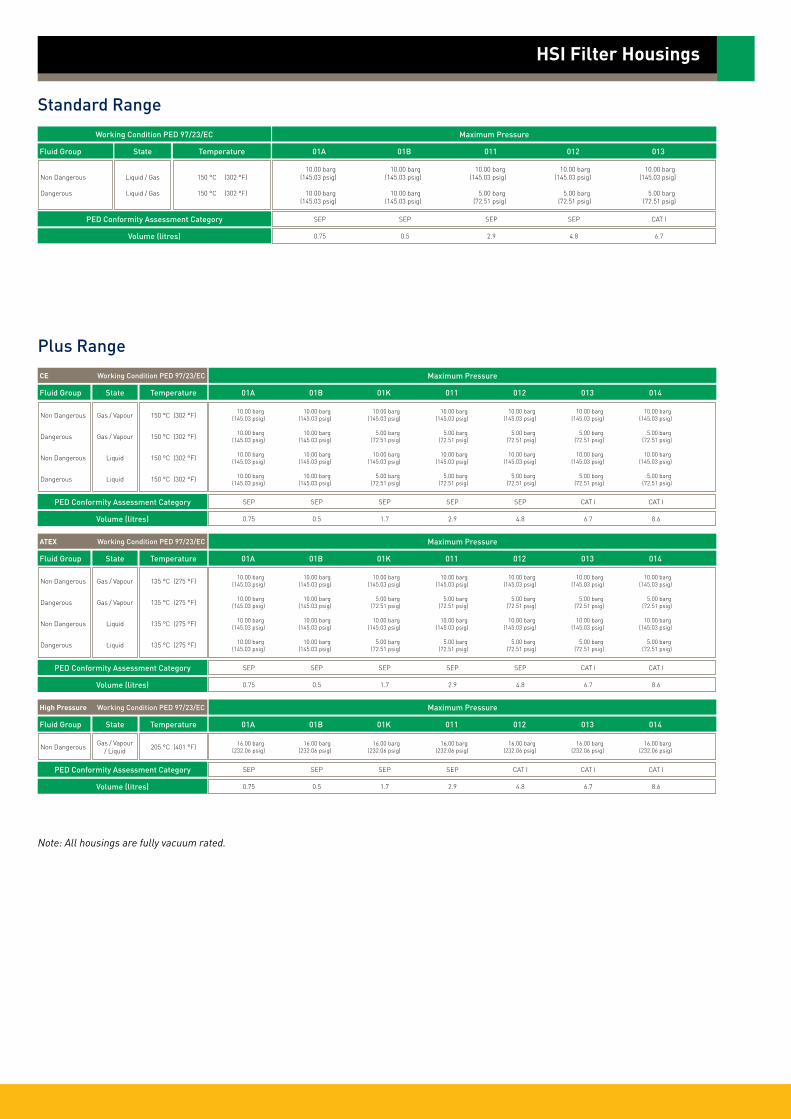
HSI Filter Housings
Standard Range
Working Condition PED 97/23/EC
Non Dangerous
Dangerous
Fluid Group State Temperature
Liquid / Gas
Liquid / Gas
150 °C (302 °F)
150 °C (302 °F)
PED Conformity Assessment Category
Volume (litres)
01A 01B 011 012 013
Maximum Pressure
10.00 barg 10.00 barg 10.00 barg 10.00 barg 10.00 barg (145.03 psig) (145.03 psig) (145.03 psig) (145.03 psig) (145.03 psig)
10.00 barg 10.00 barg 5.00 barg 5.00 barg 5.00 barg (145.03 psig) (145.03 psig) (72.51 psig) (72.51 psig) (72.51 psig)
SEP SEP SEP SEP CAT I
0.75 0.5 2.9 4.8 6.7
Plus Range
High Pressure Working Condition PED 97/23/EC
Non Dangerous
Fluid Group State Temperature
Gas / Vapour / Liquid 205 °C (401 °F)
PED Conformity Assessment Category
Volume (litres)
01A 01B 01K 011 012 013 014
Maximum Pressure
16.00 barg 16.00 barg 16.00 barg 16.00 barg 16.00 barg 16.00 barg 16.00 barg (232.06 psig) (232.06 psig) (232.06 psig) (232.06 psig) (232.06 psig) (232.06 psig) (232.06 psig)
SEP SEP SEP SEP CAT I CAT I CAT I
0.75 0.5 1.7 2.9 4.8 6.7 8.6
ATEX Working Condition PED 97/23/EC
Non Dangerous
Dangerous
Non Dangerous
Dangerous
Fluid Group State Temperature
Gas / Vapour
Gas / Vapour
Liquid
Liquid
135 °C (275 °F)
135 °C (275 °F)
135 °C (275 °F)
135 °C (275 °F)
PED Conformity Assessment Category
Volume (litres)
01A 01B 01K 011 012 013 014
Maximum Pressure
10.00 barg 10.00 barg 10.00 barg 10.00 barg 10.00 barg 10.00 barg 10.00 barg (145.03 psig) (145.03 psig) (145.03 psig) (145.03 psig) (145.03 psig) (145.03 psig) (145.03 psig)
10.00 barg 10.00 barg 5.00 barg 5.00 barg 5.00 barg 5.00 barg 5.00 barg (145.03 psig) (145.03 psig) (72.51 psig) (72.51 psig) (72.51 psig) (72.51 psig) (72.51 psig)
10.00 barg 10.00 barg 10.00 barg 10.00 barg 10.00 barg 10.00 barg 10.00 barg (145.03 psig) (145.03 psig) (145.03 psig) (145.03 psig) (145.03 psig) (145.03 psig) (145.03 psig)
10.00 barg 10.00 barg 5.00 barg 5.00 barg 5.00 barg 5.00 barg 5.00 barg (145.03 psig) (145.03 psig) (72.51 psig) (72.51 psig) (72.51 psig) (72.51 psig) (72.51 psig)
SEP SEP SEP SEP SEP CAT I CAT I
0.75 0.5 1.7 2.9 4.8 6.7 8.6
CE Working Condition PED 97/23/EC
Non Dangerous
Dangerous
Non Dangerous
Dangerous
Fluid Group State Temperature
Gas / Vapour
Gas / Vapour
Liquid
Liquid
150 °C (302 °F)
150 °C (302 °F)
150 °C (302 °F)
150 °C (302 °F)
PED Conformity Assessment Category
Volume (litres)
01A 01B 01K 011 012 013 014
Maximum Pressure
10.00 barg 10.00 barg 10.00 barg 10.00 barg 10.00 barg 10.00 barg 10.00 barg (145.03 psig) (145.03 psig) (145.03 psig) (145.03 psig) (145.03 psig) (145.03 psig) (145.03 psig)
10.00 barg 10.00 barg 5.00 barg 5.00 barg 5.00 barg 5.00 barg 5.00 barg (145.03 psig) (145.03 psig) (72.51 psig) (72.51 psig) (72.51 psig) (72.51 psig) (72.51 psig)
10.00 barg 10.00 barg 10.00 barg 10.00 barg 10.00 barg 10.00 barg 10.00 barg (145.03 psig) (145.03 psig) (145.03 psig) (145.03 psig) (145.03 psig) (145.03 psig) (145.03 psig)
10.00 barg 10.00 barg 5.00 barg 5.00 barg 5.00 barg 5.00 barg 5.00 barg (145.03 psig) (145.03 psig) (72.51 psig) (72.51 psig) (72.51 psig) (72.51 psig) (72.51 psig)
SEP SEP SEP SEP SEP CAT I CAT I
0.75 0.5 1.7 2.9 4.8 6.7 8.6
Note: All housings are fully vacuum rated.

Dim ‘A’
Dim ‘B’
Dim ‘C’Bowl Removal Height
HSI Filter Housings
Inlet Port11/2¨ Tri-Clamp
Bowl
Body Clamp
Body Seal
Head
Outlet Port11/2¨ Tri-Clamp
Drain Port1/2¨ Tri-Clamp
Physical Characteristics
Bowl Height
A Size 125 mm (5¨)
B Size 65 mm (21/2¨)
250 mm (10¨)
500 mm (20¨)
750 mm (30¨)
63.5 mm (2.5¨) 207 mm (8.1¨) 130 mm (5.1¨)
63.5 mm (2.5¨) 152 mm (6.0¨) 70 mm (2.8¨)
101.6 mm (4¨) 449 mm (17.7¨) 313 mm (12.3¨)
101.6 mm (4¨) 699 mm (27.5¨) 561 mm (22.1¨)
101.6 mm (4¨) 944 mm (37.2¨) 809 mm (31.9¨)
1.0 Kg (2.2lbs)
0.8 Kg (0.03lbs)
3.6 Kg (7.9 lbs)
4.6 Kg (10.1 lbs)
5.6 Kg (12.3 lbs)
Dimensions (mm) ‘A’ ‘B’ ‘C’ Typical Weight
The PLUS product range is available with many options of connections, vents, drains, surface finish, seals classification, etc. Please see product coding.
Example: Showing Demi A Size with 1¨ connections
Dimensions shown are based on the STANDARD range. For accurate dimensions, please contact Parker domnick hunter.

STANDARD Range - 10¨ to 30¨
HSI -
Code ǀ Length (Nominal)
1 10¨ (250 mm)2 20¨ (500 mm)3 30¨ (750 mm)
Code ǀ Connection Size
Y 11/2¨ (38.1 mm)
Code ǀ Cartridge
C 226
Code ǀ Vessel Class
CE Standard
Code ǀ Standard
T Tri-Clamp
Code ǀ Seal
S Silicone
-01
HSI Filter Housings
PLUS Range - K to 40¨
HSI
Code ǀ Length (Nominal)
K 5¨ (125 mm)1 10¨ (250 mm)2 20¨ (500 mm)3 30¨ (750 mm)4 40¨ (1000 mm)
Code ǀ Connection Size
Y 11/2¨ (38.1 mm)
Code ǀ Cartridge
C 226
Code ǀ Vessel Class
CE StandardAT ATEXHP* High Pressure
Code ǀ Standard
T Tri-Clamp
Code ǀ Seal
E EPDMP* PTFES SiliconeV Viton
01
Code ǀ Vent
H 11/2¨ TCF & HosebarbI 11/2¨ TCF & Staubli RBE03M 11/2¨ TCF & 1/2¨ TCFR 11/2¨ TCF & Rectus 21X No Vent
Code ǀ Drain
H HosebarbR Rectus 21S Staubli RBE03T 1/2¨ TCFX No Drain
Code ǀ Surface Finish Internal External
B Sanitary 0.4 µm 0.25 µmP Sanitary Electropolished 0.4 µm EP 0.25 µm
Code ǀ Tagged
T YesX No
- - -
For Tagged Options customer identification numbers required at time of ordering
* Double bolted clamp required
* Supplied complete with a double bolted clamp
PLUS Range - Demi A & B
HSI
Code ǀ Length (Nominal)
A 5¨ (125 mm)B 21/2¨ (65 mm)
Code ǀ Connection Size
Y 11/2¨
Code ǀ Cartridge
T 126
Code ǀ Vessel Class
CE StandardAT ATEXHP* High Pressure
Code ǀ Standard
T Tri-Clamp
Code ǀ Seal
E EPDMP* PTFES SiliconeV Viton
01
Code ǀ Vent
H(1) 11/2¨ TCF & HosebarbI (1) 11/2¨ TCF & Staubli RBE03M (1) 11/2¨ TCF & 1/2¨ TCFR (1) 11/2¨ TCF & Rectus 21X No Vent
Code ǀ Drain
H HosebarbR Rectus 21S Staubli RBE03 T 1/2¨ TCFX No Drain
Code ǀ Surface Finish Internal External
B Sanitary 0.4 µm 0.25 µmP Sanitary Electropolished 0.4 µm EP 0.25 µm
Code ǀ Tagged
T YesX No
- - -
For Tagged Options customer identification numbers required at time of ordering
(1) Vent is part of inlet connection
* Double bolted clamp required
STANDARD Range - Demi A & B
HSI -
Code ǀ Length (Nominal)
A 5¨ (125 mm)B 21/2¨ (65 mm)
Code ǀ Connection Size
Y 11/2¨
Code ǀ Cartridge
T 216
Code ǀ Vessel Class
CE Standard
Code ǀ Standard
T Tri-Clamp
Code ǀ Seal
S Silicone
-01
* Supplied complete with a double bolted clamp
DS_HS_51_01/11_2AParker domnick hunter has a continuous policy of product development and although the Company reserves the right to change specifications, it attempts to keep customers informed of any alterations. This publication is for general information only and customers are requested to contact our Process Filtration Sales Department for detailed information and advice on a products suitability for specific applications. All products are sold subject to the company’s Standard conditions of sale.
Euro
pe:
+44
(0)1
91 4
1051
21
dhp
roce
ss@
park
er.c
om -
Nor
th A
mer
ica:
✆ +
1 60
8 82
4 05
00
dhp
sale
s.na
@pa
rker
.com
w
ww.
park
er.c
om/d
hpha
rma

Specification
HIL Filter Housings
• industrial liquid
STANDARD RangeMaterials of Construction Housing: Cast Head - Stainless Steel Bowl - 316L Stainless Steel Seals: EPDM FDA Clamps: 304 Stainless Steel
Surface Finish Internal: As Welded External: Polished 0.8 µm Ra (32 µIn Ra) All finishes pickled & passivated.
PLUS RangeMaterials of Construction Housing: Cast Head - Stainless Steel Bowl - 316L Stainless Steel Seals: EPDM FDA PTFE FDA Silicone FDA Viton FDA Clamps: 304 Stainless Steel
Surface FinishTwo Finished Available: Standard Finish Head-Cast, Pickled & Passivated Bowl Internal: As Welded Pickled & Passivated Bowl External: Polished 0.8 µm Ra (32 µIn Ra) Standard Electropolished Finish Head-Cast, Pickled & Passivated Bowl Internal: Electropolished Bowl External: Polished 0.8 µm Ra (32 µIn Ra)
WeldingAll assembly welds are full penetration. All welds are crevice and undercut free.Weld finish & detail drawings available upon request.
CertificationSupplied as standard with vessel inspection certificate.
Material Test CertificationEN10204 3.1 supplied upon request.
Design CodeHousings designed in accordance with the European Council Pressure Equipment Directive (PED) 97/23/EC and the UK statutory Pressure Equipment Regulations (PER) 1999 N° 2001.
PED / PER conformity assessments based on Fluid Group 2 Gas (harmless) including steam. Only housings over PS.V 50 bar / litres bear the CE mark. Design BasisASME VIII Division 1.
• Industrial liquid housing for prefiltration and clarification duties
• STANDARD product − BSP (G) or NPT connections and standard finish
• PLUS product − Available in 3 different vessel classes:
Standard (CE), Atex & High Pressure − Standard and electropolished surface finishes
available − A number of inlet / outlet port connections − Choice of BSP, NPT or no vent − Choice of BSP or NPT drain − Option of C (226) location and fabricated
(not cast) head
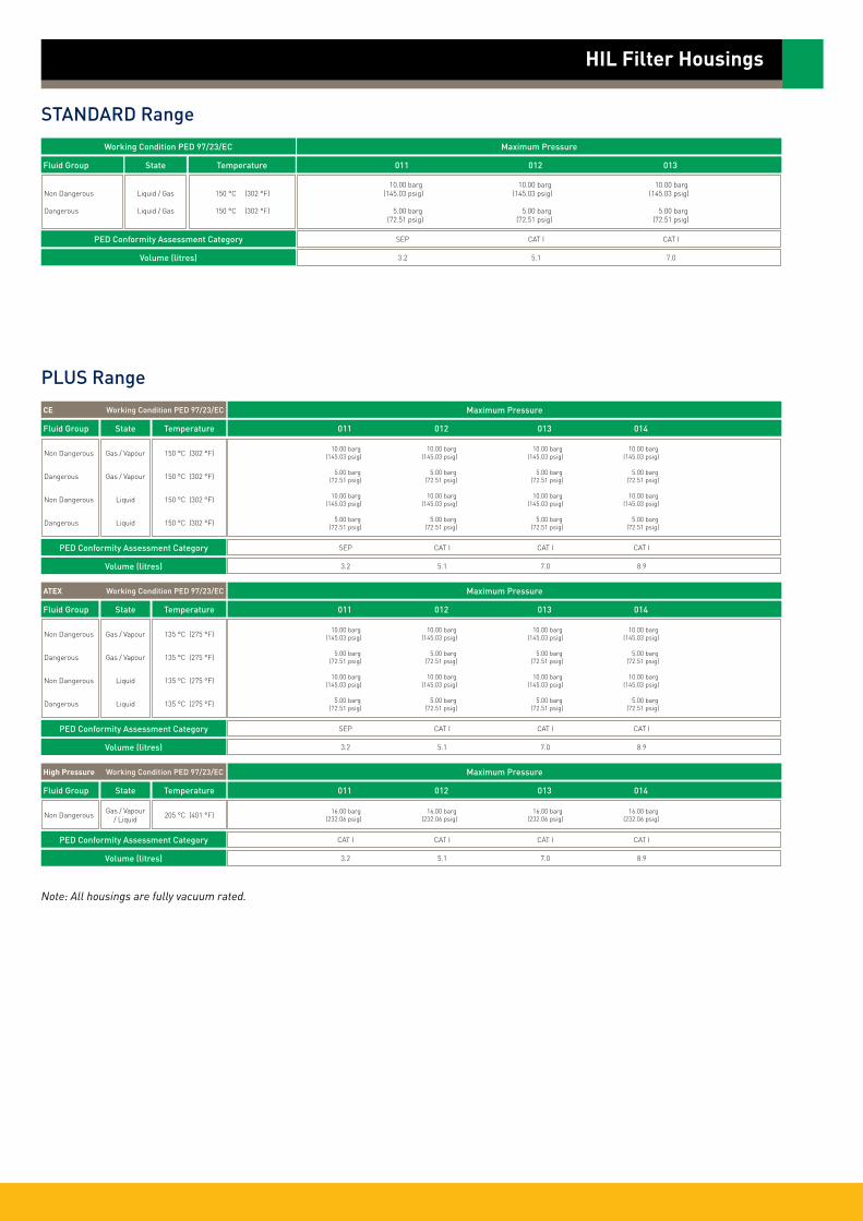
HIL Filter Housings
STANDARD Range
Working Condition PED 97/23/EC
Non Dangerous
Dangerous
Fluid Group State Temperature
Liquid / Gas
Liquid / Gas
150 °C (302 °F)
150 °C (302 °F)
PED Conformity Assessment Category
Volume (litres)
011 012 013
Maximum Pressure
10.00 barg 10.00 barg 10.00 barg (145.03 psig) (145.03 psig) (145.03 psig)
5.00 barg 5.00 barg 5.00 barg (72.51 psig) (72.51 psig) (72.51 psig)
SEP CAT I CAT I
3.2 5.1 7.0
PLUS Range
High Pressure Working Condition PED 97/23/EC
Non Dangerous
Fluid Group State Temperature
Gas / Vapour / Liquid 205 °C (401 °F)
PED Conformity Assessment Category
Volume (litres)
011 012 013 014
Maximum Pressure
16.00 barg 16.00 barg 16.00 barg 16.00 barg (232.06 psig) (232.06 psig) (232.06 psig) (232.06 psig)
CAT I CAT I CAT I CAT I
3.2 5.1 7.0 8.9
ATEX Working Condition PED 97/23/EC
Non Dangerous
Dangerous
Non Dangerous
Dangerous
Fluid Group State Temperature
Gas / Vapour
Gas / Vapour
Liquid
Liquid
135 °C (275 °F)
135 °C (275 °F)
135 °C (275 °F)
135 °C (275 °F)
PED Conformity Assessment Category
Volume (litres)
011 012 013 014
Maximum Pressure
10.00 barg 10.00 barg 10.00 barg 10.00 barg (145.03 psig) (145.03 psig) (145.03 psig) (145.03 psig)
5.00 barg 5.00 barg 5.00 barg 5.00 barg (72.51 psig) (72.51 psig) (72.51 psig) (72.51 psig)
10.00 barg 10.00 barg 10.00 barg 10.00 barg (145.03 psig) (145.03 psig) (145.03 psig) (145.03 psig)
5.00 barg 5.00 barg 5.00 barg 5.00 barg (72.51 psig) (72.51 psig) (72.51 psig) (72.51 psig)
SEP CAT I CAT I CAT I
3.2 5.1 7.0 8.9
CE Working Condition PED 97/23/EC
Non Dangerous
Dangerous
Non Dangerous
Dangerous
Fluid Group State Temperature
Gas / Vapour
Gas / Vapour
Liquid
Liquid
150 °C (302 °F)
150 °C (302 °F)
150 °C (302 °F)
150 °C (302 °F)
PED Conformity Assessment Category
Volume (litres)
011 012 013 014
Maximum Pressure
10.00 barg 10.00 barg 10.00 barg 10.00 barg (145.03 psig) (145.03 psig) (145.03 psig) (145.03 psig)
5.00 barg 5.00 barg 5.00 barg 5.00 barg (72.51 psig) (72.51 psig) (72.51 psig) (72.51 psig)
10.00 barg 10.00 barg 10.00 barg 10.00 barg (145.03 psig) (145.03 psig) (145.03 psig) (145.03 psig)
5.00 barg 5.00 barg 5.00 barg 5.00 barg (72.51 psig) (72.51 psig) (72.51 psig) (72.51 psig)
SEP CAT I CAT I CAT I
3.2 5.1 7.0 8.9
Note: All housings are fully vacuum rated.

Dim ‘A’
Dim ‘B’ Dim ‘C’Bowl Removal Height
Vent Plug
Cartridge Tie Rod
Bowl
Drain Port
Inlet Port
Vent Seal
Cast Head
Outlet Port
Cartridge Centralising Piece
Body Clamp
Body Seal
Cartridge Tie Rod Nut
Drain Seal
Drain Plug
Vent Port
Retention Spring
The PLUS product range is available with many options of connections, vents, drains, surface finish, seals classification, etc. Please see product coding.
Example: Showing 10¨ Size with 1¨ connections
Bowl Height
250 mm (10¨)
500 mm (20¨)
750 mm (30¨)
150 mm (5.9¨) 441 mm (17.4¨) 297 mm (11.7¨)
150 mm (5.9¨) 691 mm (27.2¨) 550 mm (21.7¨)
150 mm (5.9¨) 936 mm (26.9¨) 814 mm (32.0¨)
1.5 Kg (3.3 lbs) 1.2 Kg (2.6 lbs) 3.8 Kg (8.4 lbs)
2.5 Kg (5.5 lbs) 1.2 Kg (2.6 lbs) 4.9 Kg (10.8 lbs)
3.5 Kg (7.7 lbs) 1.2 Kg (2.6 lbs) 6.0 Kg (13.2 lbs)
Dimensions (mm) ‘A’ ‘B’ ‘C’
Typical Weight Bowl Head Total
HIL Filter Housings
Physical Characteristics
Dimensions shown are based on the STANDARD range. For accurate dimensions, please contact Parker domnick hunter.

STANDARD Range - 10¨ to 30¨
HIL -
Code ǀ Length (Nominal)
1 10¨ (250 mm)2 20¨ (500 mm)3 30¨ (750 mm)
Code ǀ Connection Size
B 1¨ (25.4 mm)
Code ǀ Cartridge
B DOED 222
Code ǀ Vessel Class
CE Standard
Code ǀ Standard
B BSPPN NPT
Code ǀ Seal
E EPDM
-01
PLUS Range - 10¨ to 40¨
HIL
Code ǀ Length (Nominal)
1 10¨ (250 mm)2 20¨ (500 mm)3 30¨ (750 mm)4 40¨ (1000 mm)
Code ǀ Connection Size
B 1¨ (25.4 mm)Y 11/2¨ (38.1 mm)
Code ǀ Cartridge
B DOEC 226 (Fabricated Head)
D 222
Code ǀ Vessel Class
CE StandardAT ATEXHP* High Pressure
Code ǀ Standard
B* BSPP (F)F ANSI RF150(1)
H ANSI RF 300L BS4504 DIN2633N* NPT (F)T*° Tri-clamp
Code ǀ Seal
E EPDMP* PTFES SiliconeV Viton
01
Code ǀ Vent
B 1/4¨ BSPPN 1/4¨ NPTX° No Vent
Code ǀ Drain
B 1/4¨ BSPP (G1/4̈ )N 1/4¨ NPT
Code ǀ Surface Finish Internal External
E Standard Electropolished Electropolished 0.8 µmI Standard As Welded 0.8 µm
Code ǀ Tagged
T YesX No
- - -
* Only available in 1¨connection(1) Not suited for High Pressure Vessels. HP Vessels to use ANSI RF 300.° Only available with ‘C’ Style cartridge configuration
For Tagged Options customer identification numbers required at time of ordering
°Only available with ‘C’ Style cartridge configuration
* Double bolted clamp required
* Supplied complete with a double bolted clamp
HIL Filter Housings
Bowl Height
250 mm (10¨)
500 mm (20¨)
750 mm (30¨)
1000 mm (40¨)
176 mm (6.9¨) 472 mm (18.6¨) 297 mm (11.7¨)
176 mm (6.9¨) 722 mm (28.4¨) 550 mm (25.4¨)
176 mm (6.9¨) 967 mm (38.1¨) 814 mm (32.0¨)
176 mm (6.9¨) 1217 mm (47.9¨) 1058 mm (41.7¨)
Dimensions (mm) ‘A’* ‘B’ ‘C’
*156 mm without vent
Dim ‘B’
Dim ‘C’
Dim ‘A’
ø101.6
Important Note: As shown on the coding chart above, the HIL is also available with an option ‘C’ (226) location. This design incorporates a machined, not cast, head and swept bend connections, as show in the diagram.
DS_HS_52_01/11_2AParker domnick hunter has a continuous policy of product development and although the Company reserves the right to change specifications, it attempts to keep customers informed of any alterations. This publication is for general information only and customers are requested to contact our Process Filtration Sales Department for detailed information and advice on a products suitability for specific applications. All products are sold subject to the company’s Standard conditions of sale.
Euro
pe:
+44
(0)1
91 4
1051
21
dhp
roce
ss@
park
er.c
om -
Nor
th A
mer
ica:
✆ +
1 60
8 82
4 05
00
dhp
sale
s.na
@pa
rker
.com
w
ww.
park
er.c
om/d
hpha
rma

Specification
HCA Enhanced PlusFilter Housing• Alloy 22 gas housings
Materials of Construction Housing: Alloy 22 (Stainless Steel non-wetted parts) Seals: PTFE, EPDM, Silicone or Viton (All FDA) Vent / Drain Seals: PTFE (BSP Only)
Surface Finish Internal: Polished 0.8 µm Ra External: Polished 0.8 µm Ra All finishes pickled & passivated. WeldingAll assembly welds are full penetration. All welds are crevice and undercut free.Weld finish & detail drawings available upon request.
CertificationSupplied as standard with vessel inspection certificate.
Material Test CertificationEN10204 3.1 supplied upon request.
Design CodeHousings designed in accordance with the European Council Pressure Equipment Directive (PED) 97/23/EC and the UK statutory Pressure Equipment Regulations (PER) 1999 N° 2001.
PED / PER conformity assessments based on Fluid Group 1 Gas (dangerous) liquid and gases. Only housings over PS.V 25 bar / litres bear the CE mark. Design BasisASME VIII Division 1.ATEX 94/9/EC (where applicable).
• Flow efficient range of gas housings
• Single element housing
• Designed to maximize flow and minimize pressure drop
• Designed specifically for aggressive gases and solvents
• Suitable for cartridge type 226, K to 30¨
•Wetted parts Alloy 22 - Non wetted parts 304 and 316 stainless steel
Non Dangerous
Dangerous
Fluid Group State Temperature 01K 011 012 013
Maximum Pressure
Liquid / Gas 150 °C (302 °F) 10.00 barg 10.00 barg 10.00 barg 10.00 barg (145.03 psig) (145.03 psig) (145.03 psig) (145.03 psig)
PED Conformity Assessment Category SEP SEP CAT I CAT 1
Volume (litres) 1.3 2.2 3.5 4.8
ATEX Working Condition PED 97/23/EC
Non Dangerous
Dangerous
Fluid Group State Temperature 01K 011 012 013
Maximum Pressure
Liquid / Gas 135 °C (275 °F) 10.00 barg 10.00 barg 10.00 barg 10.00 barg (145.03 psig) (145.03 psig) (145.03 psig) (145.03 psig)
PED Conformity Assessment Category SEP SEP CAT I CAT 1
Volume (litres) 1.3 2.2 3.5 4.8
C22 Working Condition PED 97/23/EC
Note: All housings are fully vacuum rated.
Important Note(Export restrictions may apply)In response to International Law, Parker Hannifin require that any orders for Alloy 22 products are accompanied by written notification from the end user stating their company name, address and product application.

Physical Characteristics
HCA Enhanced Plus Filter Housings
Bowl Dimensions (mm) Weight (Kg) Height ‘A’ Bowl Head Total
5¨ (125 mm) 250 2.0 3.0 5.0
10¨ (250 mm) 370 3.0 3.0 6.0
20¨ (500 mm) 615 5.0 3.0 8.0
30¨ (750 mm) 865 7.0 3.0 10.0
Dimensions are based on illustration shown.For accurate dimensions, please contact Parker domnick hunter.
DS_HS_43_01/11_2A
Ordering InformationHCA
Code ǀ Length (Nominal)
K 5¨ (125 mm)1 10¨ (250 mm)2 20¨ (500 mm)3 30¨ (750 mm)
Code ǀ Connection Size
C+ 2¨ (50.80 mm)Y* 11/2¨ (48.26 mm)
Code ǀ Cartridge
C 226
Code ǀ Material
22 C22
Code ǀ Standard
B BSPP (F)F (1) ANSI RF 150H (1) ANSI RF 300L (1) BS4504 DIN2633N NPT (F)T 2¨ Tri-Clamp
Code ǀ Seal
E EPDMP PTFES SiliconeV Viton
01
Code ǀ Vent
B 1/4¨ BSPP (F)N 1/4¨ NPT (F)
Code ǀ Drain
B 1/4¨ BSPPN 1/4¨ NPT
Code ǀ Surface Finish Internal External
E Electropolished Electropolished 0.8 µmI Standard As Welded 0.8 µm
Code ǀ Tagged
T YesX No
- - -
For Tagged Options customer identification numbers required at time of ordering
(1) Loose stainless 316 lap joint flange
224mm
Dim ‘A’
52m
m
Alloy 22 Lap Joint Flange (with loose 316 backing flange)
1/4¨ BSP (G1/4¨) or NPT Vent Plug
Inlet Port
Bowl
PTFE Drain Seal(BSP Only)
PTFE Vent Seal(BSP Only)
1/4¨ BSP (G1/4¨) or NPT Vent Plug
Double Bolted Tri-Clamp (304)
PTFE Tri-Clamp Body Seal
Outlet Port
22 Alloy 22AT ATEX
+ Tri-Clamp only* Nominal Bore
Parker domnick hunter has a continuous policy of product development and although the Company reserves the right to change specifications, it attempts to keep customers informed of any alterations. This publication is for general information only and customers are requested to contact our Process Filtration Sales Department for detailed information and advice on a products suitability for specific applications. All products are sold subject to the company’s Standard conditions of sale.
Euro
pe:
+44
(0)1
91 4
1051
21
dhp
roce
ss@
park
er.c
om -
Nor
th A
mer
ica:
✆ +
1 60
8 82
4 05
00
dhp
sale
s.na
@pa
rker
.com
w
ww.
park
er.c
om/d
hpha
rma

Specification
HCL Enhanced PlusFilter Housing• Alloy 22 liquid housings
Materials of Construction Housing: Alloy 22 (Stainless Steel non-wetted parts) Seals: PTFE, EPDM, Silicone or Viton (All FDA) Vent / Drain Seals: PTFE (BSP Only)
Surface Finish Internal: Polished 0.8 µm Ra External: Polished 0.8 µm Ra All finishes pickled & passivated. WeldingAll assembly welds are full penetration. All welds are crevice and undercut free.Weld finish & detail drawings available upon request.
CertificationSupplied as standard with vessel inspection certificate.
Material Test CertificationEN10204 3.1 supplied upon request.
Design CodeHousings designed in accordance with the European Council Pressure Equipment Directive (PED) 97/23/EC and the UK statutory Pressure Equipment Regulations (PER) 1999 N° 2001.
PED / PER conformity assessments based on Fluid Group 1 Gas (dangerous) liquid and gases. Only housings over PS.V 25 bar / litres bear the CE mark. Design BasisASME VIII Division 1.ATEX 94/9/EC (where applicable).
• Flow efficient range of liquid housings
• Range of inlet / outlet standard connections
• Designed specifically for aggressive liquids
• Suitable for cartridge types 226, K to 30¨
•Wetted parts Alloy 22 - Non wetted parts 304 and 316 stainless steel
C22 Working Condition PED 97/23/EC
Non Dangerous
Dangerous
Fluid Group State Temperature 01K 011 012 013
Maximum Pressure
Liquid / Gas 150 °C (302 °F) 10.00 barg 10.00 barg 10.00 barg 10.00 barg (145.03 psig) (145.03 psig) (145.03 psig) (145.03 psig)
PED Conformity Assessment Category SEP SEP CAT I CAT 1
Volume (litres) 1.3 2.2 3.5 4.8
ATEX Working Condition PED 97/23/EC
Non Dangerous
Dangerous
Fluid Group State Temperature 01K 011 012 013
Maximum Pressure
Liquid / Gas 135 °C (275 °F) 10.00 barg 10.00 barg 10.00 barg 10.00 barg (145.03 psig) (145.03 psig) (145.03 psig) (145.03 psig)
PED Conformity Assessment Category SEP SEP CAT I CAT 1
Volume (litres) 1.3 2.2 3.5 4.8
Note: All housings are fully vacuum rated.
Important Note(Export restrictions may apply)In response to International Law, Parker Hannifin require that any orders for Alloy 22 products are accompanied by written notification from the end user stating their company name, address and product application.

Physical Characteristics
HCL Enhanced Plus Filter Housings
224mm
Dim ‘A’
Bowl Dimensions (mm) Weight (Kg) Height ‘A’ Bowl Head Total
5¨ (125 mm) 240 2.0 3.0 5.0
10¨ (250 mm) 360 3.0 3.0 6.0
20¨ (500 mm) 607 5.0 3.0 8.0
30¨ (750 mm) 855 7.0 3.0 10.0
Double Bolted Tri-Clamp (304)
1/4¨ BSP (G1/4¨) or NPT Vent Plug
Inlet Port
23m
m
Tri-Clamp Body Seal
Bowl
PTFE Drain Seal(BSP Only)
PTFE Vent Seal(BSP Only)
Dimensions are based on illustration shown. For accurate dimensions, please contact Parker domnick hunter.
DS_HS_44_01/11_2A
Ordering Information
HCL
Code ǀ Length (Nominal)
K 5¨ (125 mm)1 10¨ (250 mm)2 20¨ (500 mm)3 30¨ (750 mm)
Code ǀ Connection Size
B* 1¨ (33.4 mm)Y+ 11/2¨ (38.1 mm)
Code ǀ Cartridge
C 226 (Fabricated Head)
Code ǀ Material
22 Alloy 22AT ATEX
Code ǀ Standard
B BSPP (F)F (1) ANSI RF150H (1) ANSI RF 300L (1) BS4504 DIN2633N NPT (F)T 11/2¨ Tri-Clamp
Code ǀ Seal
E EPDMP PTFES SiliconeV Viton
01
Code ǀ Vent
B 1/4¨ BSPPN 1/4¨ NPT
Code ǀ Drain
B 1/4¨ BSPPN 1/4¨ NPT
Code ǀ Surface Finish Internal External
E Electropolished Electropolished 0.8 µmI Standard As Welded 0.8 µm
Code ǀ Tagged
T YesX No
- - -
(1) Loose stainless steel 316 Lab Joint Flange
For Tagged Options customer identification numbers required at time of ordering
1/4¨ BSP (G1/4¨) or NPT Vent Plug
Outlet Port
C22 Lap Joint Flange (with loose 316 backing flange)
* Nominal Bore+ Tri-Clamp Only
Parker domnick hunter has a continuous policy of product development and although the Company reserves the right to change specifications, it attempts to keep customers informed of any alterations. This publication is for general information only and customers are requested to contact our Process Filtration Sales Department for detailed information and advice on a products suitability for specific applications. All products are sold subject to the company’s Standard conditions of sale.
Euro
pe:
+44
(0)1
91 4
1051
21
dhp
roce
ss@
park
er.c
om -
Nor
th A
mer
ica:
✆ +
1 60
8 82
4 05
00
dhp
sale
s.na
@pa
rker
.com
w
ww.
park
er.c
om/d
hpha
rma

Specification
ZVA Housings
• air / gas
Materials of Construction Housing: 316L Stainless Steel Seals: EPDM
Surface Finish Multis - Basic Specification Internal: Inside of outlet assy and distribution box to be mechanically polished 0.8 µm Ra. Immerse entire vessel to achieve 100% pickle and passivation. External: Grit blast 5 µm Ra mean
Multis - Full Specification Internal: Electropolish 0.6 µm Ra External: Bright Polished 0.4 µm Ra
Maximum Allowable Working Pressure (MAWP) PS6 barg ( 87.0 psig)
Maximum Allowable Working Temperature (MAWT) TS 120 °C (248 °F)
Maximum Allowable Working Pressure Steam3 barg (43.5 psig) @ 144 °C (291 °F)
Total Volume (litres)
Design CodeHousings designed in accordance with the European Council Pressure Equipment Directive (PED) 97/23/EC and the UK statutory Pressure Equipment Regulations (PER) 1999 N° 2001. PED / PER conformity assessments based on Fluid Group 2 Gas (harmless) including steam. Only housings over PS.V 50 bar / litres bear the CE mark.
Design BasisASME VIII Division 1.
Custom DesignParker domnick hunter offers a specialist and fabrication service allowing individual customer system specifications to be met.
• Sanitary range air / gas housing
• Specifically designed for the Pharmaceutical industry
• Laboratory and pilot scale to large industrial applications
• Flow efficient design with low pressure drop
• Steam jacketed and electrically heated options
031 032 033
31.0 40.0 49.0
051 052 053
45.0 58.0 72.0

ZVA Housings
Ordering Information
ZVA -
Code ǀ Length (Nominal)
1 10¨ (250 mm)2 20¨ (500 mm)3 30¨ (750 mm)
Code ǀ Connection Size
D 3¨E 4¨G 6¨H 8¨
Code ǀ Vent / Drain Conn. Type
B BSPP
Code ǀ Connection Standard
A NPT / ANSIN Nominal BoreI ISO
Code ǀ Surface Finish
C Economy SpecF Full Spec
--
Code ǀ Connection Type
F FlangedW Weld Prepared
-
Code ǀ N° of Cartridges
03 305 509 915 15
Physical Characteristics
Dim ‘A’
Dim ‘B’
Vent Plug
Dim ‘C’Bowl Removal Height
Vent / Gauge Port
Bowl
Body ClosureNut & Washer
Filter CartridgeSpider Plate
Body Seal
Body Closure Stud Bolt
Head
Outlet Port
Drain
Inlet Port
Drain Plug
Bowl Dimensions (mm) Typical Height ‘A’ ‘B’ ‘C’ Weight
10¨ (250 mm) 336 794 320 43.0
20¨ (500 mm) 336 1044 570 47.0
30¨ (750 mm) 336 1294 820 50.0
Dimensions shown are for a ZVACE 3 round, 3¨ ANSI inlet / outlet connections. For the full range of dimensions and weights, please contact Parker domnick hunter.
Code ǀ Vessel Class
CE Standard
Note: For accessories, i.e. gauges, please contact Parker domnick hunter - Process Division for full availability.
DS_HS_27_01/11_2A
Note: All housings are fully vacuum rated.
Parker domnick hunter has a continuous policy of product development and although the Company reserves the right to change specifications, it attempts to keep customers informed of any alterations. This publication is for general information only and customers are requested to contact our Process Filtration Sales Department for detailed information and advice on a products suitability for specific applications. All products are sold subject to the company’s Standard conditions of sale.
Euro
pe:
+44
(0)1
91 4
1051
21
dhp
roce
ss@
park
er.c
om -
Nor
th A
mer
ica:
✆ +
1 60
8 82
4 05
00
dhp
sale
s.na
@pa
rker
.com
w
ww.
park
er.c
om/d
hpha
rma

Specification
VIS Housings
• high flow steam
Materials of Construction Housing: 316L Stainless Steel Seals: EPDM
Surface Finish Internal: Inside of outlet and distribution box to be mechanically mirror polished 0.8 µm Ra. Immerse vessel to achieve 100% pickle and passivation. External: Grit blast 5 µm Ra mean
Maximum Allowable Working Pressure (MAWP) PS7 barg (101.5 psig)
Maximum Allowable Working Temperature (MAWT) TS 170.5 °C (339 °F)
Design CodeHousings designed in accordance with the European Council Pressure Equipment Directive (PED) 97/23/EC and the UK statutory pressure equipment regulations (PER) 1999 N° 2001. PED / PER Conformity assessments based on Fluid Group 2 Gas (harmless) allowing for in-situ steam sterilisation. Only housings over PS.V 50 bar / litres bear the CE mark.
Design BasisASME VIII Division 1.
• Specifically designed to maximize flow rates and minimize pressure drop
• Compatible with JUMBO element to maximize steam capacity

VIS Housings
Ordering Information
VIS
Code ǀ N° of Cartridges
01 103 3
Code ǀ Connection Size
D* 3¨E* 4¨G** 6¨H** 8¨
Code ǀ Connection Type
D BS4504 PN16 FlangeA ANSI cl. 150 Flange
-
Code ǀ Length (Nominal)
J Jumbo
-
Physical Characteristics
Dim ‘A’
Dim ‘B’
Dim ‘C’Bowl Removal Height
Vent Plug1/4¨ BSPP
Vent / Gauge Port 1/4¨ BSPP (F)
Bowl
Outlet Port3¨ BS4504 PN16
Inlet Port3¨ BS4504 PN16
Drain Plug1/4¨ BSPP
Body Seal
Body Closure Stud Bolt
Drain1/4¨ BSPP (F)
Body ClosureNut & Washer
Dimensions (mm) Typical Type ‘A’ ‘B’ ‘C’ Weight
VISCE-01J -DD 300 763 310 30.0
VISCE-01J -ED 330 895 140 50.0
VISCE-3J -DD 515 1049 410 100.0
VISCE-3J -ED 700 1237 490 150.0
Code ǀ Vessel Class
CE Standard
For the full range of dimensions and weights, please contact Parker domnick hunter.
* Single housings only ** Round housings only
Note: For accessories, i.e. gauges, please contact Parker domnick hunter - Process Division for full availability.
DS_HS_28_01/11_2A
Note: All housings are fully vacuum rated.
Parker domnick hunter has a continuous policy of product development and although the Company reserves the right to change specifications, it attempts to keep customers informed of any alterations. This publication is for general information only and customers are requested to contact our Process Filtration Sales Department for detailed information and advice on a products suitability for specific applications. All products are sold subject to the company’s Standard conditions of sale.
Euro
pe:
+44
(0)1
91 4
1051
21
dhp
roce
ss@
park
er.c
om -
Nor
th A
mer
ica:
✆ +
1 60
8 82
4 05
00
dhp
sale
s.na
@pa
rker
.com
w
ww.
park
er.c
om/d
hpha
rma

Specification
VSL Housings
• sanitary liquid
Materials of Construction Housing: 316L Stainless Steel Seals: EPDM
Surface Finish Internal: Electropolished 0.4 µm Ra External: Polished 0.25 µm Ra
Economy SpecAn economy version is available with a lower specification, external linished to 0.8 µm Ra.
Design CodeHousings designed in accordance with the European Council Pressure Equipment Directive (PED) 97/23/EC and the UK statutory pressure equipment regulations (PER) 1999 N° 2001. PED / PER Conformity assessments based on Fluid Group 2 Gas (harmless) allowing for in-situ steam sterilisation. Only housings over PS.V 50 bar / litres bear the CE mark.
Design BasisASME VIII.
Custom DesignParker domnick hunter offers a specialist and fabrication service allowing individual customer system specifications to be met.
•Multi-element sanitary liquid housing
• Designed specifically for the pharmaceutical industry
• Electropolished internal finish
Working Condition PED 97/23/EC
Non Dangerous
Dangerous / Non Dangerous
Fluid Group State Temperature 3 / 5 Round 3 / 5 Round 3 / 5 Round
Maximum Pressure
Liquids
Gas / Vapour
80 °C (176 °F)
144 °C (297 °F)
7.00 barg 7.00 barg 7.00 barg (101.50 psig) (101.50 psig) (101.50 psig)
3.00 barg 3.00 barg 3.00 barg (43.50 psig) (43.50 psig) (43.50 psig)
PED Conformity Assessment Category CAT I CAT II CAT II
Volume (litres) 10.7 18.5 26.3
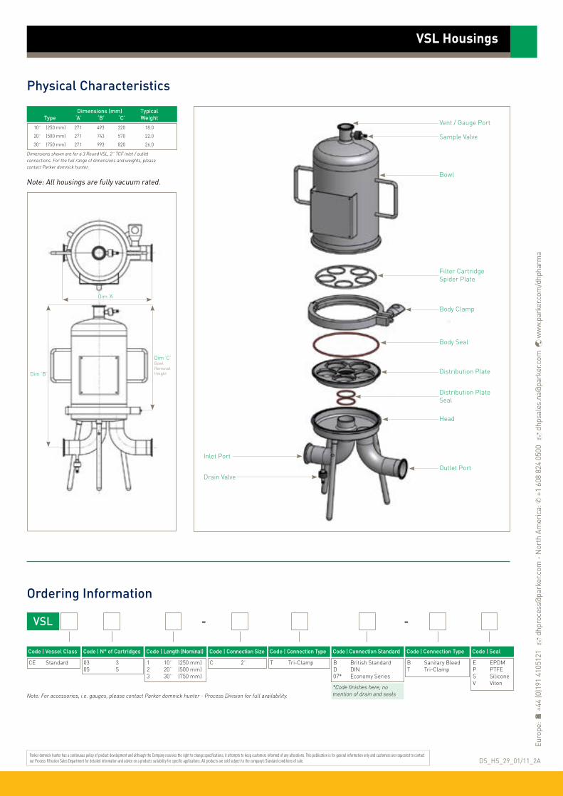
VSL Housings
Ordering Information
VSL -
Code ǀ Length (Nominal)
1 10¨ (250 mm)2 20¨ (500 mm)3 30¨ (750 mm)
Code ǀ Connection Size
C 2¨
Code ǀ N° of Cartridges
03 305 5
Code ǀ Connection Standard
B British StandardD DIN07* Economy Series
Code ǀ Seal
E EPDMP PTFES SiliconeV Viton
Code ǀ Connection Type
T Tri-Clamp
-
*Code finishes here, no mention of drain and seals
Code ǀ Connection Type
B Sanitary BleedT Tri-Clamp
Physical Characteristics
Dim ‘A’
Dim ‘B’
Dim ‘C’Bowl Removal Height
Vent / Gauge Port
Sample Valve
Bowl
Filter Cartridge Spider Plate
Body Clamp
Outlet Port
Inlet Port
Drain Valve
Body Seal
Distribution Plate
Distribution PlateSeal
Head
Dimensions (mm) Typical Type ‘A’ ‘B’ ‘C’ Weight
10¨ (250 mm) 271 493 320 18.0
20¨ (500 mm) 271 743 570 22.0
30¨ (750 mm) 271 993 820 26.0
Dimensions shown are for a 3 Round VSL, 2¨ TCF inlet / outlet connections. For the full range of dimensions and weights, please contact Parker domnick hunter.
Code ǀ Vessel Class
CE Standard
Note: For accessories, i.e. gauges, please contact Parker domnick hunter - Process Division for full availability.
DS_HS_29_01/11_2A
Note: All housings are fully vacuum rated.
Parker domnick hunter has a continuous policy of product development and although the Company reserves the right to change specifications, it attempts to keep customers informed of any alterations. This publication is for general information only and customers are requested to contact our Process Filtration Sales Department for detailed information and advice on a products suitability for specific applications. All products are sold subject to the company’s Standard conditions of sale.
Euro
pe:
+44
(0)1
91 4
1051
21
dhp
roce
ss@
park
er.c
om -
Nor
th A
mer
ica:
✆ +
1 60
8 82
4 05
00
dhp
sale
s.na
@pa
rker
.com
w
ww.
park
er.c
om/d
hpha
rma

Specification
VIL Multi Filter Housing
• industrial multi liquid
Materials of Construction Housing: 316L Stainless Steel Seals: EPDM
Surface Finish Internal / External: DOE Economy: As fabricated then pickled to remove weld discolouration DOE Standard: As fabricated then electropolished P-7 (226) o-ring: As fabricated then electropolished
Design CodeHousings designed in accordance with the European Council Pressure Equipment Directive (PED) 97/23/EC and the UK statutory Pressure Equipment Regulations (PER) 1999 N° 2001.
Design BasisASME VIII Division 1.
Custom DesignParker domnick hunter offers a specialist and fabrication service allowing individual customer system specifications to be met.
•Multi-element industrial liquid housing
• Laboratory and pilot scale to large industrial applications
• Flow efficient design with low pressure drop
Working Condition PED 97/23/EC
Non Dangerous
Fluid Group State Temperature 3 / 5 Round 8 Round 12 Round
Maximum Pressure
Liquids 80 °C (176 °F) 10.00 barg 8.50 barg 6.00 barg (145.00 psig) (123.00 psig) (87.00 psig)
PED Conformity Assessment Category SEP SEP SEP
Volume (litres)
031 032 033
14.0 19.0 24.0
051 052 053 054
20.0 28.0 36.0 44.0
082 083 084
70.0 87.0 104.0
122 123 124
98.0 122.0 146.0
Applications • General prefiltration duties of low hazard Group 2
chemicals including edible oils, coolants and cutting oils.
• General prefiltration of water and drinks in the Food & Beverage industry.

VIL Multi Filter Housings
Ordering Information
VIL
Code ǀ Length (Nominal)
1 10¨ (250 mm)2 20¨ (500 mm)3 30¨ (750 mm)4 40¨ (1000 mm)
Code ǀ Connection Size
C 2¨D 3¨ E 4¨
Code ǀ N° of Cartridges
03 305 508 812 1215° 15
Code ǀ Connection Style
B DOEC P-7
Code ǀ Seals
E EPDMP*** PTFES SiliconeV Viton
Code ǀ Connection Type
B BSPP FemaleF FlangedN NPT Female
Physical Characteristics
Dim ‘A’
Dim ‘B’
Vent Plug
Dim ‘C’Bowl Removal Height
Code ǀ Surface Finish
E ElectropolishedP** Pickled
Code ǀ Flange Type*
15 ANSI cl. 15045 BS4504
Vessel Cap
Tie-Rod Nut
Body Clamp
Filter Cartridge Spider PlateBody Seal
Bowl / Head
Outlet Port
Inlet Port
Partial Drain Plug
Full Drain Plug
Dimensions (mm) Typical Type ‘A’ ‘B’ ‘C’ Weight
10¨ (250 mm) 222 720 70 14.0
20¨ (500 mm) 222 970 70 16.0
30¨ (750 mm) 222 1220 70 18.0
40¨ (1000 mm) 222 1470 70 20.0
Dimensions shown are for a 3 Round VIL, 2¨ BSPP inlet / outlet connections. For the full range of dimensions and weights, please contact Parker domnick hunter.
Code ǀ Vessel Class
CE Standard
Note: * Only applicable for housings with flange connection type ** Pickled finish option only available for DOE housings *** PTFE seal option requires flanged closure
Code ǀ Cartridge Length (dh standard)
S Slimline L 10¨, 20¨, 30¨, 40¨
Note: For accessories, i.e. gauges, please contact Parker domnick hunter - Process Filtration for full availability.
DS_HS_30_02/12_2B
Note: All housings are fully vacuum rated.
Type Vent Drain
VILCE03 1/4¨ 1/2¨
VILCE05 1/4¨ 1/2¨
VILCE08 1/4¨ 1/2¨
VILCE12 1/2¨ 1¨
Upper Drain
Lower Drain
° Slimline only
Parker domnick hunter has a continuous policy of product development and although the Company reserves the right to change specifications, it attempts to keep customers informed of any alterations. This publication is for general information only and customers are requested to contact our Process Filtration Sales Department for detailed information and advice on a products suitability for specific applications. All products are sold subject to the company’s Standard conditions of sale.
Euro
pe:
+44
(0)1
91 4
1051
21
dhp
roce
ss@
park
er.c
om -
Nor
th A
mer
ica:
✆ +
1 60
8 82
4 05
00
dhp
sale
s.na
@pa
rker
.com
w
ww.
park
er.c
om/d
hpha
rma
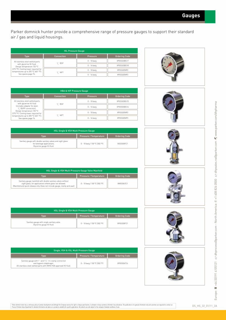
Parker domnick hunter provide a comprehensive range of pressure gauges to support their standard air / gas and liquid housings.
HIL Pressure Gauge
All stainless steel wetted parts with glycerine fill fluid.
Design temperature 135 °C (275 °F). Cooling tower required for temperatures up to 205 °C (401 °F).
See spares page 74.
Type Connection
1/4¨ BSP
Pressure
0 - 10 barg XPGSS03BS17
0 - 16 barg XPGSS03BS18
1/4¨ NPT0 - 10 barg XPGSS03NP2
0 - 16 barg XPGSS03NP3
Ordering Code
HBA & HIF Pressure Gauge
All stainless steel wetted parts with glycerine fill fluid
(includes adapter for plain1/4¨BSPP connection).
Design temperature 135 °C (275 °F). Cooling tower required for temperatures up to 205 °C (401 °F).
See spares page 74.
Type Connection
1/4¨ BSP
Pressure
0 - 10 barg XPGSS03BS15
0 - 16 barg XPGSS03BS16
1/4¨ NPT0 - 10 barg XPGSS03NP2
0 - 16 barg XPGSS03NP3
Ordering Code
HSL Single & VSH Multi Pressure Gauge
Sanitary gauge with double sanitary valves and sight glass for beverage applications. Glycerine gauge fill fluid.
Type Pressure / Temperature
0 - 10 barg / 150 °C (302 °F) XGSSS08TC1
Ordering Code
HSL Single & VSH Multi Pressure Gauge Valve Manifold
Sanitary gauge manifold with double sanitary valves without sight glass, for applications where glass not allowed.
(Manifold and quick release only. Does not include gauge, clamp and seal)
Type Pressure / Temperature
0 - 10 barg / 150 °C (302 °F) XMISS06TC1
Ordering Code
Gauges
HSL Single & VSH Multi Pressure Gauge
Sanitary gauge with single sanitary valve. Glycerine gauge fill fluid.
Type Pressure / Temperature
0 - 10 barg / 150 °C (302 °F) XPGSS08TC1
Ordering Code
Single, VSH & VSL Multi Pressure Gauge
Sanitary gauge with 1¨ and 11/2¨ tri-clamp connection and hygienic diaphragm.
All stainless steel wetted parts with KN92 FDA approved fill fluid.
Type Pressure / Temperature
0 - 10 barg / 150 °C (302 °F) XPGSS06TC4
Ordering Code
Parker domnick hunter has a continuous policy of product development and although the Company reserves the right to change specifications, it attempts to keep customers informed of any alterations. This publication is for general information only and customers are requested to contact our Process Filtration Sales Department for detailed information and advice on a products suitability for specific applications. All products are sold subject to the company’s Standard conditions of sale. DS_HS_32_01/11_2A
Euro
pe:
+44
(0)1
91 4
1051
21
dhp
roce
ss@
park
er.c
om -
Nor
th A
mer
ica:
✆ +
1 60
8 82
4 05
00
dhp
sale
s.na
@pa
rker
.com
w
ww.
park
er.c
om/d
hpha
rma

Parker domnick hunter provide a comprehensive range of manual valves to support their standard air / gas and liquid housings.
Industrial 1 Piece Ball Valve
316 stainless steel 1 piece ball valve with PTFE ball. Male / female.
Type Connection
1/4¨ BSP XVASS03BS
1/4¨ NPT XVASS03NP
Ordering Code
2 Piece Ball Valve
316 stainless steelsemi-sanitary ball valve.
(for use on up-stream connection on sanitary liquid beverage or
pharamceutical housings
Type Connection
1 / 11/2¨ Tri-Clamp - 20 mm Hosebarb XVASS06TC
Ordering Code
Valves
Butterfly Valves
Stainless steel butterfly valve with silicone seals and polymer handle.
Type Variant
1¨ OD x 1.6 Weld End XVASS05OD1/VHPL
Ordering Code
11/2¨ OD x 1.6 Weld End XVASS06OD1/VHPL
2¨ OD x 1.6 Weld End XVASS07OD1/VHPL
21/2¨ OD x 1.6 Weld End XVASS08OD1/VHPL
3¨ OD x 1.6 Weld End XVASS09OD1/VHPL
DN25 DIN11851 XVASS05DN1/VHPL
DN40 DIN11851 XVASS06DN1/VHPL
DN50 DIN11851 XVASS07DN1/VHPL
DN65 DIN11851 XVASS08DN1/VHPL
DN80 DIN11851 XVASS09DN1/VHPL
1¨ Tri-clamp Ferrule XVASS05TC4/VHPL
11/2¨ Tri-clamp Ferrule XVASS06TC4/VHPL
2¨ Tri-clamp Ferrule XVASS07TC4/VHPL
21/2¨ Tri-clamp Ferrule XVASS08TC4/VHPL
3¨ Tri-clamp Ferrule XVASS09TC4/VHPL
Sanitary Bleed Valve
316 stainless steel sanitary bleed valve with Neoprene grip.
Available with EPDM, Silicon, Vitonor Perlast Seals.
Available with Rectus 21, Staubli RBE03 or 8 mm hosebarb.
Type Variant
Staubli RBE03 Male XVASS30NA1
Ordering Code
Rectus 21 Male XVASS30RT
8 mm Hosebarb XVASS30HB
Staubli RBE03 Male XVASS30ST1
Rectus 21 Male XVASS30RT1
8 mm Hosebarb XVASS30HB1
Seals
EPDM
Silicone
Sample Valve
316 stainless steel sanitary valve with 1¨ / 11/2¨ tri-clamp connection
and 12 mm hosebarb.For use on down-stream connection
on sanitary liquid housings.
Type Connection
1 / 11/2¨ Tri-Clamp - Stepped 12 mm Hosebarb
XVASS05TC3
Ordering Code
Gemu Diaphragm Valve
316 stainless steel sanitary diaphragm valve with
1/2¨ (miniclamp) tri-clamp connection and silicone
or EPDM diaphragm.
Type Connection
1/2¨ (miniclamp) tri-clamp
Variant
Silicone XVASS04TC6
Ordering Code
EPDM XVASS04TC1
Viton XVASS04TC7
PTFE XVASS04TC8
Staubli RBE03 Male XVASS30NA4
Rectus 21 Male XVASS30RT2
8 mm Hosebarb XVASS30HB2
Staubli RBE03 Male XVASS30NA2
Rectus 21 Male XVASS30RT3
8 mm Hosebarb XVASS28SL15
Viton
Perlast
Parker domnick hunter has a continuous policy of product development and although the Company reserves the right to change specifications, it attempts to keep customers informed of any alterations. This publication is for general information only and customers are requested to contact our Process Filtration Sales Department for detailed information and advice on a products suitability for specific applications. All products are sold subject to the company’s Standard conditions of sale. DS_HS_33_01/11_2A
Euro
pe:
+44
(0)1
91 4
1051
21
dhp
roce
ss@
park
er.c
om -
Nor
th A
mer
ica:
✆ +
1 60
8 82
4 05
00
dhp
sale
s.na
@pa
rker
.com
w
ww.
park
er.c
om/d
hpha
rma

Parker domnick hunter provide a comprehensive range of spare parts to support their standard air / gas and liquid housings.
Spares
4¨ Spares
4¨ Single Pin Tri-Clamp4¨ Double Bolt Tri-Clamp
Size & Type Part Code
XTCSS10SLXTCSS10HP15
4¨ TCF Gasket EPDM4¨ TCF Gasket Silicone4¨ TCF Gasket Viton4¨ Gasket PTFE
XTSEP10ILXTSSI10SLXTSVI10SLXTSPT10SL
21/2¨ Spares
21/2¨ Single Pin Tri-Clamp21/2¨ Double Bolt Tri-Clamp
Size & Type Part Code
XTCSS08SAXTCSS08HP
21/2¨ TCF Gasket EPDM21/2¨ TCF Gasket Silicone21/2¨ TCF Gasket Viton21/2¨ Gasket PTFE
XGKEP08NAXGKSI08
XGKVI08SAXGKPT10SA
21/2¨ & 4¨ Spares
1/4¨ BSP Plug1/4¨ NPT Plug
Size & Type Part Code
XPLSS03BS4XPLSS03NP1
1/4¨ BSP PTFE Plug Seal XGKPT03BP
ATEX Earth Kit (Replacement) XEKSS00AT
11/2¨ Tri-Clamp Blanking Kit - EPDM11/2¨ Tri-Clamp Blanking Kit - Silicone11/2¨ Tri-Clamp Blanking Kit - Viton11/2¨ Tri-Clamp Blanking Kit - PTFE
XAKSS06TC6XAKSS06TC3XAKSS06TC7XAKSS06TC8
1/2¨ Tri-Clamp Blanking Kit - EPDM1/2¨ Tri-Clamp Blanking Kit - Silicone1/2¨ Tri-Clamp Blanking Kit - Viton1/2¨ Tri-Clamp Blanking Kit - PTFE
XAKSS04TC1XAKSS04TC2XAKSS04TC3XAKSS04TC4
11/2¨ Tri-Clamp Gasket - EPDM11/2¨ Tri-Clamp Gasket - Silicone11/2¨ Tri-Clamp Gasket - Viton11/2¨ Tri-Clamp Gasket - PTFE
XGKEPTCXTSSI06
XGKVI06TC2XGKPT06TC
1/2¨ Tri-Clamp Gasket - EPDM1/2¨ Tri-Clamp Gasket - Silicone1/2¨ Tri-Clamp Gasket - Viton1/2¨ Tri-Clamp Gasket - PTFE
XGKEP04TC1XGKSI04TCXGKVI04TCXGKPT04TC
Sanitary Seal Kit - EPDMSanitary Seal Kit - SiliconeSanitary Seal Kit - VitonSanitary Seal Kit - Perlast
XOREP30XORSI30XORVI30
XORPE30NA1
11/2¨ TC Blank11/2¨ TC Clamp
XTBSS05TCXTCSS05TC
1/2¨ TC Blank1/2¨ TC Clamp
XTBSS04TCXTCSS04TC
Parker domnick hunter provide a comprehensive range of certificates to support their standard air / gas and liquid housings.
Certificates
Certificate
Vessel Inspection Certificate (included with vessel)
Type
60 950 0013
Ordering Code
Vessel Inspection Certificate (replacement) 60 950 0013
Material Certification Pack (EN10204 3.1) 60 950 0014
Certificate of Conformity 60 950 0015
Passivation Report 60 950 0016
Cleanliness Certificate 60 950 0017
Surface Finish Certificate 60 950 0018
Weld Procedure Certificate Pack 60 950 0019
Quality Plan 60 950 0026
Replacement IOMI (Installation, Operation and Maintenance Instructions) 17 950 0769
3 Round VSH Spares
3 Round Body ‘V’ Clamp
Size & Type Part Code
XBCSS51BL
3 Round Spider Plate XSPSS51BL
Body O-Ring BS362 - Silicone XORSI12BL
11/2¨ Head to Elbow Gasket - PTFE XGKPT06BL
5 Round VSH Spares
5 Round Body ‘V’ Clamp
Size & Type Part Code
XBCSS52BL
5 Round Spider Plate XSCSS52BL
Body O-Ring BS370 - Silicone XORSI12BL1
2¨ Head to Elbow Gasket - PTFE XGKPT07
8 Round VSH Spares
8 Round Body ‘V’ Clamp
Size & Type Part Code
XBCSS53BL
8 Round Spider Plate XSPSS52BL
Body O-Ring BS378 - Silicone XORSI13BL
3¨ Head to Elbow Gasket - PTFE XGKPT09BL
VSH Spares
3, 5 & 8 Round Vent and Drain Clamp / Gasket Kit
Size & Type Part Code
XAKSS06TC5
HIL 222 SpringHIL DOE Nut
XSNSS07ODXNTSS01IL
Cooling Tower 1/4¨ BSPPCooling Tower 1/4¨ NPT
XCTSS03BSXCTSS03NP
Parker domnick hunter has a continuous policy of product development and although the Company reserves the right to change specifications, it attempts to keep customers informed of any alterations. This publication is for general information only and customers are requested to contact our Process Filtration Sales Department for detailed information and advice on a products suitability for specific applications. All products are sold subject to the company’s Standard conditions of sale. DS_HS_34_01/11_2A
Euro
pe:
+44
(0)1
91 4
1051
21
dhp
roce
ss@
park
er.c
om -
Nor
th A
mer
ica:
✆ +
1 60
8 82
4 05
00
dhp
sale
s.na
@pa
rker
.com
w
ww.
park
er.c
om/d
hpha
rma

TURBOSEP is a key part of Parker domnick hunter’s filtration solutions for fermentation applications.
Specifically designed for the removal of foam aggregate and aerosol from fermenter off-gas, TURBOSEP improves the overall efficiency of the fermentation process and facilitates the effective operation of final sterilizing grade filters.
This highly efficient mechanical separator has no moving parts and very low pressure drop. Foam, aerosol and entrained liquid removal from the off-gas are returned to the fermenter housing thereby minimizing product loss.
TURBOSEP is a patented product of Parker domnick hunter.
Features and Benefits
Installation of TURBOSEP
TURBOSEP
• mechanical separator• off-gas filtration
Typical InstallationWhen off-gas exits the fermenter it enters the TURBOSEP unit. Fixed turbine blades spin the incoming air forcing foam and liquid to the outer walls.
The off-gas then flows across a specially designed impingement plate and spirals down the wall of the TURBOSEP. The off-gas is now free of foam and entrained liquid and exits the TURBOSEP.
• Highly efficient separation of liquid and foam from off-gas
• Increases fermenter capacity by up to 30%
• Protection of off-gas filters for extended life
• Reduction in antifoam usage of up to 70%
• Continuous operation of the fermenter throughout the foaming process
• Improved downstream processing efficiency through reduced antifoam consumption
FERMENTER
AN
TIFO
AM
TURBOSEP™
CONTROLSYSTEM
STERILE AIRFILTER
STERILE AIRPREFILTER
(Optional for multi-batch protection)
dP Signal
dP Signal
Signal for Valve Actuation
Real-TimedP Output in
Control Room
Note: TURBOSEP is a registered trademark of Parker domnick hunter

TURBOSEP
Ordering Information
ApplicationsTURBOSEP can be employed in any fermentation application where the creation of foam is causing process control problems. This includes:
Healthcare products (e.g. penicillin, cephalosporin) Food and feed additives (e.g. lysine, M.S.G.) Organic chemicals (e.g. citric acid) Enzymes (e.g. proteases, carbohydrases)
Process OptimizationWhen employed with a differential pressuremonitoring unit, TURBOSEP optimizes the fermentation process by utilizing off-gas separation and antifoam injection.
When foam-over occurs, foam and liquid entering the TURBOSEP cause an increase in the differential pressure monitoring unit which triggers the controlled release of antifoam, at a predetermined level of foam-over, into the fermenter.
This process control system has proven to substantially reduce the levels of antifoam required to control foam-over and has led to fermenter capacity being increased in many applications.
Validated cleaning via internal spray balls
Typical Process Flow Rate (A l / min) (Acfm)
200 7.0 500 17.7 1000 35.0 2000 71.0 3000 105.0
TURBOSEP Code
ZVT-200-BTE ZVT-500-BTE ZVT-1K-BTE ZVT-2K-CTE ZVT-3K-CTE
Pipe Connection *1
3/4¨ Tri-Clamp 1¨ Tri-Clamp 11/2¨ Tri-Clamp 2¨ Tri-Clamp 21/2¨ Tri-Clamp
Typical Process Flow Rate (A m3 / min) (Acfm)
5 176 10 350 20 707 40 1414 60 2118 90 3177 120 4236
TURBOSEP Code
ZVT-5K ZVT-10K ZVT-20K ZVT-40K ZVT-60K ZVT-90K ZVT-120K
Pipe Connection *2
3¨ Weld Prepared 4¨ Weld Prepared 6¨ Weld Prepared 8¨ Weld Prepared 10¨ Weld Prepared 12¨ Weld Prepared 14¨ Weld Prepared
TURBOSEP sizing is normally based upon the completion of a TURBOSEP questionnaire available from Parker domnick hunter. Below we give an
indication of the product range based on the typical gas flow (actual rather than normalized) through the fermenter.
Each TURBOSEP is tailor made to its application to ensure maximum effectiveness in operation and overcome critical issues with respect to installation.
*1 Other connections styles available upon request.
*2 Pipe size is nominal bore. Connection style options include flange variants.
Parker domnick hunter has a continuous policy of product development and although the Company reserves the right to change specifications, it attempts to keep customers informed of any alterations. This publication is for general information only and customers are requested to contact our Process Filtration Sales Department for detailed information and advice on a products suitability for specific applications. All products are sold subject to the company’s Standard conditions of sale. DS_HS_36_11/12_1C ✆
+44
(0)1
91 4
1051
21
dhp
roce
ss@
park
er.c
om
ww
w.p
arke
r.com
/pro
cess
filtr
atio
n

The VALAIRDATA 3 is the next generation of fully automated, aerosol challenge integrity test unit, designed to test the integrity of sterile gas filters quickly and easily.
The VALAIRDATA 3 aerosol challenge test is fully correlated to aerosolized B.diminuta, B.subtilis and Enterobacteria phage MS2 challenges and is a recommended test methodology in the “PDA’s Sterilizing Filtration of Gas – Technical Report #40”.
The unit utilizes Parker domnick hunter’s 40 year experience in the provision of world leading sterile gas solutions by further improving the usability and sensitivity of the test process and offers significant savings in operator time.
Features
• 5.7” TFT LCD touch screen operation
• Multi-language menu availability
• Testing correlated to aerosol and viral challenges
• Developed to GAMP 5 guidelines
• Transfer of data via USB data stick
• 4GB internal memory storage
VALAIRDATA 3
• Integrity Test Unit
Note: VALAIRDATA is a registered trademark of Parker domnick hunter
Physical Parameters Languages: English, German, French, Swedish, Spanish, Italian, Portuguese & Danish Instrument size: 363mm x 155mm x 308mm Weight: 8 Kg Power supply: 3.2V / 16Ah & Mains 100-240 VAC : 50 / 60 Hz Inlet pressure required: 4.5 – 7 barg Pneumatic connections: Rectus 21 KA series Aerosol generation time: 5-600 seconds
Ordering Information
WVA-3 -
Code ǀ Description
ST StandardSE Secure
Instrument Options
Benefits
Easy to use
Portable for in-situ teting around the facility
Quick determination of filter’s ability to sterilize gas - 30 second time for 10¨ housing, 5 seconds for discs
Increased sensitivity compared to liquid based tests, especially on multi-cartridge systems
No unit specific PC software required
Standard Secure
Design Environment Approvals GAMP 5 GAMP 5
21CFR Part 11 No Yes (transferred data is user’s responsibility)
Security User LevelsOperator Operator - password protected
Administrator Administrator - password protected
Audit Trail No Yes
Parker domnick hunter has a continuous policy of product development and although the Company reserves the right to change specifications, it attempts to keep customers informed of any alterations. This publication is for general information only and customers are requested to contact our Process Filtration Sales Department for detailed information and advice on a products suitability for specific applications. All products are sold subject to the company’s Standard conditions of sale.
Euro
pe:
+44
(0)1
91 4
1051
21
dhp
roce
ss@
park
er.c
om -
Nor
th A
mer
ica:
✆ +
1 60
8 82
4 05
00
dhp
sale
s.na
@pa
rker
.com
w
ww.
park
er.c
om/d
hpha
rma
DS_P_48_07/13 Rev. 1A

The Porecheck 4 is configured for water intrusion testing, pressure decay and bubble point testing. The Porecheck 4 comes in two versions:
‘P’ Pharmaceutical (CFR) - Allows traceability and audit tracking capability‘C’ Certified - comes with password level protection
This market leading system incorporates a range of design features unique to the Porecheck 4 bringing true portability, enhanced ease of use, flexibility and reliability in challenging environments. All this within an instrument fully compliant with 21 CFR Part II.
Features and Benefits• Designed to 21 CFR Part
II and Annex II compliant environments
• Automatic compensation when used on housings located 10 metres above instrument
• Maintains resolution and accuracy regardless of filter system size 0.1 to 32 litres
• Highly portable and mains independent
• Configurable to automatically flush and drain filters
• Robust waterproof stainless steel casing
• Direct attachment to test disposable capsules
• 100 storable test programs defined in blocks
Porecheck 4 Integrity Test Unit
• water intrusion, pressure decay and bubble point testing
Note: Porecheck is a registered trademark of Parker Hannifin Corporation.

Porecheck 4 Integrity Test Unit
Physical Parameters
Water Intrusion Measurement Range (ul / t) ...
Resolution (µl) ......................................................................................
Accuracy (for a 10¨ cartridge @ 4000 µl / min)
Test Pressure (mbar) ...................................................................
Stabilisation Time ............................................................................
Test Time (t) ............................................................................................
Hardware Volume (ml) ...............................................................
100 - 99999
5
5%
350 - 6000
60 - 999 secs
30 - 999 secs
1 - 32000
Diffusional Flow Measurement (ml / min) ..........
Resolution (ml / min) ...................................................................
Accuracy (for a 10¨ cartridge @ 16 ml / min) ...
Test Pressure (mbar) ...................................................................
Stabilisation Time ............................................................................
Test Time (t) ............................................................................................
Upstream System Volume (ml) ........................................
1 - 999
0.1
5%
350 - 6000
60 - 999 secs
30 - 999 secs
1 - 32000
Bubble Point Measurement Range (mbar) .........
Resolution (mbar) ............................................................................
Accuracy......................................................................................................
450 - 5900 (min. 100 mbar above DF test pressure)
1
1% FS
‘P’ Pharmaceutical ‘C’ Certified Documentation
Storable Test Records .................................................................
USER Accounts ...................................................................................
Access USER ..........................................................................................
Access PROGRAMMER ..............................................................
Access ADMINISTRATOR .........................................................
Record Output ......................................................................................
Audit Trail Record ............................................................................
40 No Installation, Operating & Maintenance Manual
25 Unlimited Checklist of Supplied Components
Access Password & PIN Open Access Calibration & Pressure Vessel Certification
Access Password & PIN Access Password CE Declaration of Conformity
Access Password & PIN Access Password Operational Qualification Support Documentation
Printed Records & RS232 Transfer Printed Record Test Result Only Laboratory Qualification Results
256 Event Audit Trail No Suggested OQ Test Protocol
Instrument Material ......................................................................
Instrument Size ..................................................................................
Weight ............................................................................................................
Ingress Protection Class ..........................................................
Power Supply.........................................................................................
Keyboard .....................................................................................................
Inlet Pressure Required ............................................................
Test Pressure Range ....................................................................
Pneumatic Connectors ..............................................................
Storage Temperature ...................................................................
Ambient Humidity ............................................................................
Display ...........................................................................................................
Printer ...........................................................................................................
Languages ................................................................................................
Software Protection .......................................................................
Storable Test Programs ............................................................
Stainless Steel 1.4301 (AISI 304)
200 mm x 300 mm x 155 mm : 7.9¨ x 11.8¨ x 6.1¨
8.6 Kg : 20 lb
IP54
Re-chargeable Battery (12V / 3.8 Ah) & Mains (90 - 230 VAC : 50 / 60 Hz)
Remote Infrared - Alpha Numeric & Instrument Keypad - Numeric
6.5 - 8.0 barg (94 - 116 psig)
350 mbar to 6 barg (87 psig)
Stäubli RBE 0.3 Style : Stainless Steel 1.4404 (AISI 316L)
2 - 50 °C (35.5 - 122 °F)
1 - 80% RH
LCD - 20 Character x 4 Lines - Back Lit
Internally Housed Impact Dot Matrix , 24 Characters per Line
English, French, German, Spanish, Italian & Danish
Stored in Flash - EPROM
Up to 100 (in Flash - EPROM) Stored in 10 Blocks of 10 Programs
Test Accuracy
Instrument Options
Parker domnick hunter has a continuous policy of product development and although the Company reserves the right to change specifications, it attempts to keep customers informed of any alterations. This publication is for general information only and customers are requested to contact our Process Filtration Sales Department for detailed information and advice on a products suitability for specific applications. All products are sold subject to the company’s Standard conditions of sale.
Euro
pe:
+44
(0)1
91 4
1051
21
dhp
roce
ss@
park
er.c
om -
Nor
th A
mer
ica:
✆ +
1 60
8 82
4 05
00
dhp
sale
s.na
@pa
rker
.com
w
ww.
park
er.c
om/d
hpha
rma
DS_P_49_07/13 Rev. 1A

Endcap styles
A Style 223 o-rings B, L Style Flat Gaskets C Style 226 o-rings
D Style 222 o-rings E Style 222 o-rings F Style 216 / 218 o-rings
G Style 222 o-rings H Style 54 mm IDx 4 mm o-rings J Style S.O.E.
K Style 214 o-rings(internal)
N Style 213 o-rings(internal) P Style 227 o-rings
R Style 222 o-rings S Style Flat Gaskets SK Style(demi only)
T Style 126 o-rings(demi only) U Style 222 o-rings W Style 111 o-rings
(demi only)
X Style 116 o-rings(demi only)
Y Style 116 o-rings(internal) (demi only)
Z Style 116 o-rings(internal) (demi only)
Cartridge endcaps
Demi H Style 217 o-rings(demi only)
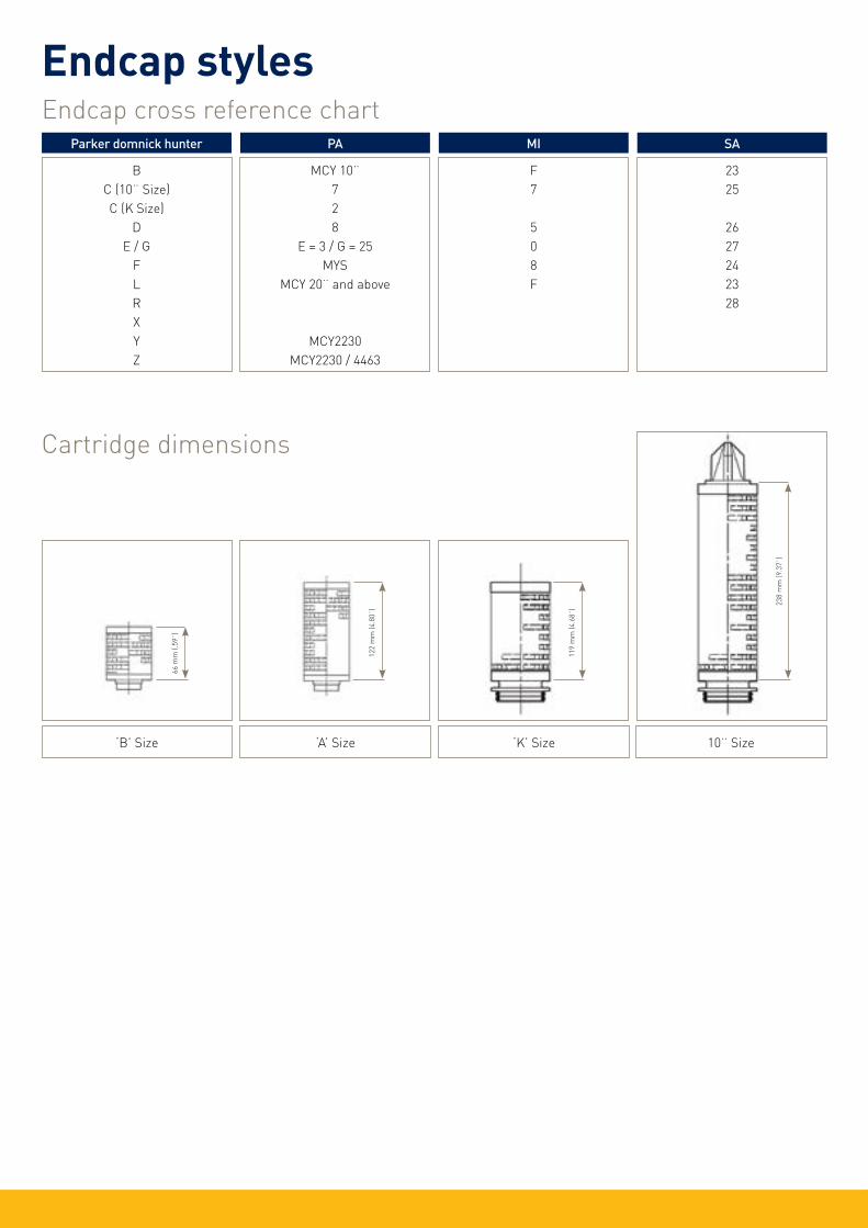
Endcap cross reference chartParker domnick hunter
BC (10¨ Size)C (K Size)
DE / G
FLRXYZ
PA MI SA
MCY 10¨728
E = 3 / G = 25MYS
MCY 20¨ and above
MCY2230MCY2230 / 4463
F7
508F
2325
2627242328
‘B’ Size ‘A’ Size ‘K’ Size 10¨ Size
Cartridge dimensions
119
mm
(4.6
8¨)
238
mm
(9.3
7¨)
122
mm
(4.8
0¨)
66 m
m (.
59¨)
Endcap styles

‘B’ Size
89 m
m (3
.5¨)
‘A’ Size
149
mm
(5.8
7¨)
‘E’ Size
64 m
m (2
.5¨)
1/2¨ Hosebarb (Code H) 1/4¨ NPT (Code N)Stepped Hosebarb (Code G)
1¨ Tri-clamp (Code T)
Gromelle (Code R)1/2¨ NPT (Code M) Walther Male (Code Q)
DEMICAP styles

27 mm (1.06¨)
Gromelle (Code R)
1/2¨ Hosebarb (Code H)
26 mm (1.02¨)
1/2¨ NPT (Code N)
23 mm (0.9¨)
Stepped Hosebarb (Code G)
34 mm (1.34¨)
1¨ Tri-clamp (Code T)
17 mm (0.67¨)
1/4¨ NPT (Code M)
26 mm (1.02¨)
Walther Male (Code Q)
28 mm (1.1¨)
DEMICAP styles

1¨ Hosebarb 3/4¨ Tri-clamp 1¨ Tri-clamp
11/2¨ Tri-clamp T-Port(1¨ Tri-Clamp only)
Large scale disposable inlet / outlet connection styles
Syringe filters
‘A’ ‘B’ ‘C’ 0.98¨ 25 mm 1.12¨ 28.5 mm 0.31¨ 8.0 mm 1.96¨ 50 mm 2.12¨ 54.0 mm 0.31¨ 8.0 mm
Example of Syringe filter marking
MURUS and syringe styles
Stepped HosebarbSuitable for tubing with 6 mm (1/4¨)
12 mm (1/2¨) internal diameterLuer Slip Male Luer Loc Female
5/16¨ Hosebarb 1/8¨ BSPM Thread
Lot N° stamped on side of filter
BC
A
Cartridge Type ‘A’ ‘B’ 10¨ 250 mm 13.07¨ 332 mm 10.30¨ 262 mm 20¨ 500 mm 22.79¨ 579 mm 20.04¨ 509 mm 30¨ 750 mm 32.56¨ 827 mm 29.80¨ 757 mm
A
B

Installation and operating guidelinesEndcap Styles
Cartridge endcaps
X Style 1/2¨ NPTM
Thread & Gasket
V Style BSPPThread & Gasket
Vent autoclave filter endcaps and dimensions0.5¨ BSPP
1826
ø30
ø63
152
25‘A’ Flats 0.5¨ BSPP
1826
ø30
88
ø63
‘B’ Size‘A’ Size
25‘A’ Flats
Cartridge dimensions
‘B’ Size‘A’ Size‘K’ Size10¨ Size
119 mm
(4.68¨)
238 mm
(9.37¨)
122 mm
(4.80¨)
66 mm
(.59¨)
IntroductionThese guidelines give the correct methods for using liquid and gas filter cartridges manufactured by Parker domnick hunter. If you have any queries, our process filtration specialists will be pleased to discuss your particular filtration requirements or answer any questions you may have. We may also be contacted at any of the addresses given on the reverse of this document or through our worldwide network of sales companies and distributors.
1. Storage1.1 Store cartridges in a clean and dry environment and avoid placing heavy objects on the top of the cartridge tube or packaging. The cartridges should not be exposed to temperatures below 5 °C (41 °F) or above 40 °C (104 °F) or to direct sunlight.1.2 Keep the cartridge in its sealed polyethylene bag until it is time to install it.1.3 The shelf-life for cartridge filters is as follows:- Liquid membrane cartridges 3 years Liquid depth cartridges 5 years TETPOR membrane variants 5 years Gas membrane cartridges 5 years Gas depth cartridges 5 years Gamma irradiated cartridges Consult Certificate of Conformance
2. InstallationThe various cartridge formats and end caps are shown on the end of this sheet. Please refer to this if you are unsure which cartridge format you have.2.1 New housings should be flushed out with clean water / air (dependant on the application) prior to installation of the cartridge to remove any debris. Ensure tie-rods / support plates are removed prior to flushing as vibration (especially in air) can cause components to loosen.2.2 Before changing or installing a liquid or gas cartridge filter ensure that the filter vessel is depressurized and any liquid has been drained off. (Most vent filter cartridges are open to atmosphere but if the filter is connected to a pressurised line then ensure that the filter vessel is depressurized before removing the filter bowl).2.3 Remove the filter bowl. For plastic housings the bowl is unscrewed and for stainless steel housings the bowl is held in place using a band clamp or a bolted flange.2.4 Cut open the polyethylene bag at the cartridge open end and check that the o-ring seals or gaskets are clean, intact, correctly located in their grooves and not damaged.2.5 Lubricate o-ring seals with a lubricant that is compatible with the process fluid (e.g. clean water) or use process liquid itself. Note: No lubricant should be used for oxygen applications.2.6 Using the bag as protection and holding the cartridge as near as possible to the open end as opposed to the main body of the cartridge or the top end cap, press the cartridge firmly into or onto the housing locations. Keep the cartridge vertical to prevent damage to the o-rings. a) If the vessel has a bayonet type cartridge location (A,C & R), slightly turn the cartridge clock-wise to locate the retaining lugs. b) For double open ended cartridges (B), take care to ensure that the cartridge gaskets on both the housing and cartridge are centred over the housing knife edge seals at both ends before closing the vessel. c) Cartridges with a threaded end cap (V) should be screwed in until the gasket is compressed. d) Threaded vent filters should be screwed into position until the flat gasket is compressed (BSPP) or the thread locks (NPT).2.7 Remove the polyethylene bag from the cartridge(s) before the vessel is closed.2.8 Some filter housings take more than one cartridge (multi-round) and they will have a support plate that locates on top of the cartridges and prevents movement and damage. Refer to the vessel instructions for the way that this plate is secured and ensure that it is always installed before the vessel bowl is located.
3. Operation (Liquid Cartridges)Filter cartridges should not be subjected to excessive hydraulic shock and should never be reverse pressurizedfrom the downstream to the upstream side (inside to out). (Except PEPLYN HA / HD).3.1 Slowly open the upstream valve and allow liquid into the filter vessel.3.2 The vent valve located at the top of the vessel should be cracked open to allow air to escape and to ensure that the filter vessel is full of liquid. The vent valve should be closed when liquid starts to exit the valve. N.B. If hazardous liquids are being filtered, please ensure that vent and drain valves are connected to a suitable drain line.3.3 Slowly open the downstream valve and allow the filtered liquid to flow. It is recommended that newly installed cartridges are briefly flushed to drain and remove any debris that may have been inadvertently generated during cartridge installation or to remove trace levels of surfactant that may be present in some filter media. Liquid cartridges are shown to be blocked when the differential pressure across the filter has significantly increased and / or the flow of liquid through them is reduced to an unacceptable level. If you do not have pressure gauges that indicate the differential pressure then please contact Parker domnick hunter or its representative.
4. Operation (Gas / Vent cartridges)Vent / gas filter cartridges are hydrophobic and they will not operate effectively if they are covered in water or steam condensate. This can lead to tank collapse or cartridge deformation so please ensure that if vent filters do come into contact with water they are replaced.
Gas cartridges are blocked when the differential pressure across the filter is high and/or the flow of gas throughthem is significantly reduced. In normal operation they should be changed at least annually.
5. Integrity TestingSome liquid and gas cartridges may be integrity tested by a number of manual or automatic methods. Please contact Parker domnick hunter or its representative for further information on which method is most suitable for your application or refer to the appropriate product datasheet.
6. Hot Water Sanitization (Liquid Hydrophilic Cartridges)Recirculate prefiltered water through the filter for 30 min at 80 °C (176 °F). The maximum differential pressure across the filter should be no more than 1 bar (14.5 psi). Open all system outlet valves to sanitize the system thoroughly.
7. Steam SterilizationPlease refer to the datasheets to find out if your cartridge filter and housing can be autoclaved or steamed in place (SIP) and the allowed maximum temperature. To minimize the risk of contamination to a sterile system the filter should be autoclaved or SIP’d immediately prior to use.N.B. Plastic housings cannot be steam sterilized or autoclaved.
Steam-in-Place (SIP)It is important that both liquid and gas filter cartridges do not have bulk steam flowed through them during SIP because excessive differential presure can cause damage to the cartridge at high temperatures. It is also usual to filter the steam so that any dirt it carries does not block or damage the filter.
Vacuum Autoclave SterilizationThe cartridge should be installed in the housing, the vent / drain valves left open and the housing bowl left slightly open. Do not allow the cartridge to support the vessel base or allow the bowl to rest on the cartridge during autoclaving. The assembly should be autoclaved on a cycle with a slow exhaust. Where possible liquid cartridges should be flushed with clean water prior to autoclaving.
Parker domnick hunter has detailed guidelines for the sanitization and steam sterilization of liquid and gas filters so if you are unsure of the procedures please contact Parker domnick hunter or it’s representative.
DisposalAll cartridge filters should be disposed of in a safe manner and in line with Health & Safety Guidelines.
English
Instrucciones de Manejo e Instalación
de los Cartuchos Filtrantes Para
Liquidos y Gases
Installation and Operating
Instructions for Liquid &
Gas Filter Cartridges
Manuel D’installation et D’utilisation
des Cartouches pour les Liquids
et les Gas
Installation und Bedienungsanleitung
Für Filterelemente zur Flüssigkeits-
und Gasfiltration
Ed
. 2010-09-29
Europe, Middle East, AfricaAE – United Arab Emirates, Dubai Tel: +971 4 8127100 [email protected]
AT – Austria, Wiener Neustadt Tel: +43 (0)2622 23501-0 [email protected]
AT – Eastern Europe, Wiener Neustadt Tel: +43 (0)2622 23501 900 [email protected]
AZ – Azerbaijan, Baku Tel: +994 50 2233 458 [email protected]
BE/LU – Belgium, Nivelles Tel: +32 (0)67 280 900 [email protected]
BY – Belarus, Minsk Tel: +375 17 209 9399 [email protected]
CH – Switzerland, Etoy Tel: +41 (0)21 821 87 00 [email protected]
CZ – Czech Republic, Klecany Tel: +420 284 083 111 [email protected]
DE – Germany, Kaarst Tel: +49 (0)2131 4016 0 [email protected]
DK – Denmark, Ballerup Tel: +45 43 56 04 00 [email protected]
ES – Spain, Madrid Tel: +34 902 330 001 [email protected]
FI – Finland, Vantaa Tel: +358 (0)20 753 2500 [email protected]
FR – France, Contamine s/Arve Tel: +33 (0)4 50 25 80 25 [email protected]
GR – Greece, Athens Tel: +30 210 933 6450 [email protected] – Hungary, Budapest Tel: +36 1 220 4155 [email protected]
IE – Ireland, Dublin Tel: +353 (0)1 466 6370 [email protected]
IT – Italy, Corsico (MI) Tel: +39 02 45 19 21 [email protected]
KZ – Kazakhstan, Almaty Tel: +7 7272 505 800 [email protected]
NL – The Netherlands, Oldenzaal Tel: +31 (0)541 585 000 [email protected]
NO – Norway, Asker Tel: +47 66 75 34 00 [email protected]
PL – Poland, Warsaw Tel: +48 (0)22 573 24 00 [email protected]
PT – Portugal, Leca da Palmeira Tel: +351 22 999 7360 [email protected]
RO – Romania, Bucharest Tel: +40 21 252 1382 [email protected]
RU – Russia, Moscow Tel: +7 495 645-2156 [email protected]
SE – Sweden, Spånga Tel: +46 (0)8 59 79 50 00 [email protected]
SK – Slovakia, Banská Bystrica Tel: +421 484 162 252 [email protected]
SL – Slovenia, Novo Mesto Tel: +386 7 337 6650 [email protected]
TR – Turkey, Istanbul Tel: +90 216 4997081 [email protected]
UA – Ukraine, Kiev Tel +380 44 494 2731 [email protected]
UK – United Kingdom, Warwick Tel: +44 (0)1926 317 878 [email protected] – South Africa, Kempton Park Tel: +27 (0)11 961 0700
Parker [email protected]
North AmericaCA – Canada, Milton, Ontario Tel: +1 905 693 3000
US – USA, Cleveland Tel: +1 216 896 3000
Asia PacificAU – Australia, Castle Hill Tel: +61 (0)2-9634 7777
CN – China, Shanghai Tel: +86 21 2899 5000
HK – Hong Kong Tel: +852 2428 8008
IN – India, Mumbai Tel: +91 22 6513 7081-85
JP – Japan, Tokyo Tel: +81 (0)3 6408 3901
KR – South Korea, Seoul Tel: +82 2 559 0400
MY – Malaysia, Shah Alam Tel: +60 3 7849 0800
NZ – New Zealand, Mt Wellington Tel: +64 9 574 1744
SG – Singapore Tel: +65 6887 6300
TH – Thailand, Bangkok Tel: +662 717 8140
TW – Taiwan, Taipei Tel: +886 2 2298 8987
South AmericaAR – Argentina, Buenos Aires Tel: +54 3327 44 4129
BR – Brazil, Sao Jose dos Campos Tel: +55 12 4009 3500
CL – Chile, Santiago Tel: +56 2 623 1216
MX – Mexico, Apodaca Tel: +52 81 8156 6000
VE – Venezuela, Caracas
Parker Hannifin Manufacturing Ltddomnick hunterProcess Filtration - EuropeDurham RoadBirtley, Co. DurhamDH3 2SF, Englandphone +44 (0)191 4105121fax +44 (0)191 4105312email: [email protected]/processfiltration
© 2011 Parker Hannifin Corporation. All rights reserved.
Stock N°: 17 950 0420Publication Reference: Rev. 2E 07/11
Parker Hannifin Corporationdomnick hunterProcess Filtration - North America2340 Eastman AvenueOxnard, California, USA 93030toll free: +1 877 784 2234phone: +1 805 604 3400fax: +1 805 604 3401email: [email protected]/processfiltration
A Style 223 o-ringsB, L Style Flat GasketsC Style 226 o-rings
D Style 222 o-ringsE Style 222 o-ringsF Style 216 / 218 o-rings
G Style 222 o-ringsH Style 54 mm IDx 4 mm o-ringsJ Style S.O.E.
K Style 214 o-rings(internal)
N Style 213 o-rings(internal)P Style 227 o-rings
R Style 222 o-ringsS Style Flat GasketsSK Style(demi only)
T Style 126 o-rings(demi only)U Style 222 o-ringsW Style 111 o-rings
(demi only)
X Style 116 o-rings(demi only)
Y Style 116 o-rings(internal) (demi only)
Z Style 116 o-rings(internal) (demi only)
Demi H Style 217 o-rings(demi only)
ConfigurationIntroductionThese guidelines give the correct methods for installing and operating Parker domnick hunter DEMICAP Capsules. If you have any queries please contact our process filtration specialists who will be pleased to discuss your particular filtration requirements or answer any questions you may have. We may also be contacted at any of the addresses given on the reverse of this document or through our worldwide network of distributors.
1. StorageStore Capsules in a clean and dry environment and avoid placing heavy objects on top of the Capsule box. Capsules should not be stored at temperatures below 5 °C (41 °F) or above 30 °C (86 °F) or in direct sunlight.1.1 The shelf-life for DEMICAP Capsules is as follows: Non-gamma irradiated 3 years Gamma irradiated 2 years PROPOR PES DEMICAP Capsules Consult Certificate of Conformance
2. Operating Conditions Liquid: Maximum 5 barg (72 psig) @ 40°C Gas: Maximum 4 barg (58 psig) @ 40°C If DEMICAP Capsules are used outside these operating conditions or with fluids that are not compatible with the materials of construction then the product body may fail and result in injury to the operator or damage to equipment.
3. Installation and OperationPlease ensure that the Capsule you have chosen is compatible with the fluid and system before installation and check that the product and part number etched on the base of the Capsule are as required.NB: If the capsule is to be used in a sterile environment please ensure that the capsule is either sterile packed by Parker domnick hunter or autoclaved prior to use. DEMICAP Capsules can not be steam sterilised in-situ.
A) Liquid Systems 1. Follow the arrows on the capsule label and ensure that the Capsule is installed in the correct direction and using the appropriate connections. 2. Before passing liquid through the capsule ensure that the vent valves are closed and the Capsule is mounted in a secure position. It is important that the Capsule is full of liquid during operation, so ensure that it is mounted so that the air can be vented in a safe manner. 3. The Capsule can be vented by turning the vent nut in an anti-clockwise direction. The valve is retained by the nut so do not undo the nut by more than 1 or 2 turns as this may result in wastage of the liquid within the Capsule or injury to the operator. After long term use of the Capsule, build up of residue on the seats of the vents valves may cause them to stick. Pulling gently on the hosebarbs after undoing the nut by a quarter turn will release them. NB: If hazardous fluids are to be passed through the Capsule, the vent valves should be connected to an appropriate drain line. 4. If the Capsule is connected into a pressurised system make sure that transient pressures do not exceed the maximum operating conditions.
B) Gas Systems 1. Follow the arrows on the capsule label and ensure that the capsule is installed in the correct direction and using the appropriate connections. For vent applications flow can be in either direction. 2. Gas filters are hydrophobic and may not allow the passage of water. It is also possible that condensation can collect in the Capsule and prevent the passage of gas. The Capsule should be mounted so that any water or condensate can be drained from the vent valves. In some cases it may be necessary to remove the Capsule and dry the membrane by passing dry air or nitrogen through it.
4. Integrity TestingSome DEMICAP Capsules can be integrity tested either off-line or in-situ. Please contact Parker domnick hunter or its representative for further information on the most appropriate method and equipment. Integrity test parameters are available in the product datasheets.
5. SterilisationDEMICAP Capsules can be autoclaved up to the maximum temperature marked on the product. Please contact Parker domnick hunter with the details of your sterilisation regime so we can advise the maximum number of cycles.NB: 1. The vent / drain valves should be left open during the autoclave cycle 2. DO NOT STEAM STERILISE DEMICAP CAPSULES IN-LINE !
6. DisposalAll Capsules should be disposed of in a safe manner and in line with Health and Safety Guidelines.
English
AE – United Arab Emirates, Dubai Tel: +971 4 8127100 [email protected]
AR – Argentina, Buenos Aires Tel: +54 3327 44 4129
AT – Austria, Wiener Neustadt Tel: +43 (0)2622 23501-0 [email protected]
AT – Austria, Wiener Neustadt Tel: +43 (0)2622 23501 970 [email protected]
AU – Australia, Castle Hill Tel: +61 (0)2-9634 7777
AZ – Azerbaijan, Baku Tel: +994 50 2233 458 [email protected]
BE/LU – Bélgica, Nivelles Tel: +32 (0)67 280 900 [email protected]
BR – Brazil, Cachoeirinha RS Tel: +55 51 3470 9144
BY – Belarus, Minsk Tel: +375 17 209 9399 [email protected]
CA – Canada, Milton, Ontario Tel: +1 905 693 3000
Tel: +41 (0) 21 821 02 30 [email protected]
CN – China, Shanghai Tel: +86 21 5031 2525
CZ – República Checa, Klecany Tel: +420 284 083 111 [email protected]
DE – Alemania, Kaarst Tel: +49 (0)2131 4016 0 [email protected]
DK – Denmark, Ballerup Tel: +45 43 56 04 00 [email protected]
ES – Spain, Madrid Tel: +34 902 33 00 01 [email protected]
FI – Finland, Vantaa Tel: +358 (0)20 753 2500 [email protected]
Sales Offices WorldwideFR – France,Contamine-sur-Arve Tel: +33 (0)4 50 25 80 25 [email protected] – Greece, Atnas
Tel: +30 210 933 6450 [email protected]
HK – Hong Kong Tel: +852 2428 8008
HU – Hungary, Budapest Tel: +36 1 220 4155 [email protected]
IE – Ireland, Dublin Tel: +353 (0)1 466 6370 [email protected]
IN – India, Mumbai Tel: +91 22 6513 7081-85
IT – Italy, Corsico (MI) Tel: +39 02 45 19 21 [email protected]
JP – Japan, Tokyo Tel: +(81) 3 6408 3901
KR – Korea, Seoul Tel: +82 2 559 0400
KZ – Kazakhstan, Almaty Tel: +7 7272 505 800 [email protected]
LV – Latvia, Riga Tel: +371 6 745 2601 [email protected]
MX – Mexico, Apodaca Tel: +52 81 8156 6000
MY – Malaysia, Subang Jaya Tel: +60 3 5638 1476
NL – The Netherlands, Oldenzaal Tel: +31 (0)541 585 000 [email protected]
NO – Norway, Ski Tel: +47 64 91 10 00 [email protected]
NZ – New Zealand, Mt Wellington Tel: +64 9 574 1744
PL – Poland, Varsovia Tel: +48 (0)22 573 24 00 [email protected]
PT – Portugal, Leca da Palmeira Tel: +351 22 999 7360 [email protected]
RO – Romania, Bucharest Tel: +40 21 252 1382 [email protected] – Russia, Moscow
Tel: +7 495 645-2156 [email protected]
SA – Republic of South Africa, Kempton Park Tel: +27 (0)11 961 0700 [email protected]
SE – Sweden, Spånga Tel: +46 (0)8 59 79 50 00 [email protected]
SG – Singapore Tel: +65 6887 6300
SK – Slovakia, Banská Bystrica Tel: +421 484 162 252 [email protected]
SL – Slovenia, Novo Mesto Tel: +386 7 337 6650 [email protected]
TH – Thailand, Bangkok Tel: +662 717 8140
TR – Turkey, Istanbul Tel: +90 216 4997081 [email protected]
TW – Taiwan, Taipei Tel: +886 2 2298 8987
UA – Ukraine, Kiev Tel +380 44 494 2731 [email protected]
UK – England, Warwick Tel: +44 (0)1926 317 878 [email protected]
US – USA, Cleveland Tel: +1 216 896 3000
VE – Venezuela, Caracas Tel: +58 212 238 5422
Stock N°: 17 950 1236 11/11 Rev. 2C
© 2011 Parker Hannifin Corporation
Instrucciones de Installaión Manejode las
Capsules DEMICAP
Installation and Operating Instructions
for DEMICAP Capsules
Instructions Pour la Mise en Service et le
Fonctionnement des Capsules DEMICAP
Installations- Und Betriebsanleitung Für
DEMICAP-Kapseln
1/2¨ Hosebarb (Code H)1/
4¨ NPT (Code M)
Stepped Hosebarb (Code G)1¨ Tri-clamp (Code T)
Gromelle (Code R)1/2¨ NPT (Code N)
Walther Male (Code Q)‘E’ Size
64 mm
(2.5¨)
‘B’ Size
89 mm
(3.5¨)
‘A’ Size
149 mm
(5.87¨)
Parker Hannifin Manufacturing Ltddomnick hunterProcess Filtration - EuropeDurham RoadBirtley, Co. DurhamDH3 2SF, Englandphone +44 (0)191 4105121fax +44 (0)191 4105312email: [email protected]/processfiltration
Parker Hannifin Corporationdomnick hunterProcess Filtration - North America2340 Eastman AvenueOxnard, California, USA 93030toll free: +1 877 784 2234phone: +1 805 604 3400fax: +1 805 604 3401email: [email protected]/processfiltration
Installation and Operating Instructionsfor MURUS Capsules
Instructions Pour la Mise en Service et leFonctionnement Des Capsules MURUS
Installations- Und Betriebsanleitung FürMURUS-Kapseln
Instrucciones de Installación Manejo de las Capsulas MURUS
Configuration
Dimensions shown are typical lengths for 11/2¨ Tri-Clamp.
Further dimensions available from Parker domnick hunter or your local representative.
1¨ Hosebarb3/4¨ Tri-Clamp
1¨ Tri-Clamp11/2¨ Tri-Clamp
1¨ Tri-Clamp (T-Port)
B
A
Dimensions
Cartridge TypeDimension ‘A’Dimension ‘B’
10¨ (250 mm)20¨ (500 mm)30¨ (750 mm)
10.30¨ (262 mm)20.04¨ (509 mm)29.80¨ (757 mm)
13.07¨ (332 mm)22.79¨ (579 mm)32.56¨ (827 mm)
English
Introduction These guidelines give the correct methods for installing and operating Parker domnick hunter MURUS Capsules. If you have any queries please contact our process filtration specialists who will be pleased to discuss your particular filtration requirements or answer any questions you may have. We may also be contacted at any of the addresses given on the reverse of this document or through our worldwide network of distributors.
1. StorageStore Capsules in a clean and dry environment and avoid placing heavy objects on top of the Capsule box. Capsules should not be stored at temperatures below 5 °C (41 °F) or above 30 °C (86 °F) or in direct sunlight.
2. Operating ConditionsParker Hannifin certify that this product complies with the European Council Pressure Equipment Directive (PED) 97/23/EC Article 3, Paragraph 3 – Sound Engineering Practise (SEP). This product is intended for use with Group 1 & 2 Dangerous and Harmless Liquids and Group 2 Harmless Gases at the following maximum operating conditions : Liquid: Maximum 5.5 barg (79.7 psig) @ 25 °C ( 77 °F) Maximum 2.8 barg (40.6 psig) @ 60 °C (140 °F) Gas: Maximum 4.0 barg (58.0 psig) @ 25 °C ( 77 °F)In compliance with PED Article 3, Paragraph 3, SEP, this product does not bear the CE mark.
3. Installation and OperationPlease ensure that the Capsule you have chosen is compatible with the fluid and system before installation and check that the product and part number etched on the base of the Capsule are as required.NB: If the capsule is to be used in a sterile environment please ensure that the capsule is either sterile packed by Parker domnick hunter or autoclaved prior to use. MURUS Capsules can not be steam sterilized in-situ.
a) Liquid Systems 1. Follow the arrows on the Capsule label and ensure that the Capsule is installed in the correct direction and using the appropriate connections. 2. Before passing liquid through the capsule ensure that the vent valves are closed and the Capsule is mounted in a secure position. It is important that the Capsule is full of liquid during operation, so ensure that it is mounted so that the air can be vented in a safe manner. 3. The Capsule can be vented by turning the vent nut in an anti-clockwise direction. The valve is retained by the nut so do not undo the nut by more than 1 or 2 turns as this may result in wastage of the liquid within the Capsule or injury to the operator. NB: If hazardous fluids are to be passed through the Capsule, the vent valves should be connected to an appropriate drain line. 4. If the Capsule is connected into a pressurized system make sure that transient pressures do not exceed the maximum operating conditions.
b) Gas Systems 1. Follow the arrows on the capsule label and ensure that the capsule is installed in the correct direction and using the appropriate connections. For vent applications flow can be in either direction. 2. Gas filters are hydrophobic and may not allow the passage of water. It is also possible that condensation can collect in the Capsule and prevent the passage of gas. The Capsule should be mounted so that any water or condensate can be drained from the vent valves. In some cases it may be necessary to remove the Capsule and dry the membrane by passing dry air or nitrogen through it.
4. Integrity TestingSome MURUS Capsules can be integrity tested either off-line or in-situ. Please contact Parker domnick hunter or its representative for further information on the most appropriate method and equipment. Integrity test parameters are available in the product datasheets.
5. SterilizationMURUS Capsules can be autoclaved up to the maximum temperature marked on the product. Please contact Parker domnick hunter with the details of your sterilization regime so we can advise the maximum number of cycles.NB: 1. The vent / drain valves should be left open during the autoclave cycle 2. DO NOT STEAM STERILIZE MURUS CAPSULES IN-LINE !
6. DisposalAll Capsules should be disposed of in a safe manner and in line with Health and Safety Guidelines.
Ed
. 2010-09-29
Europe, Middle East, AfricaAE – United Arab Emirates, Dubai Tel: +971 4 8127100 [email protected]
AT – Austria, Wiener Neustadt Tel: +43 (0)2622 23501-0 [email protected]
AT – Eastern Europe, Wiener Neustadt Tel: +43 (0)2622 23501 900 [email protected]
AZ – Azerbaijan, Baku Tel: +994 50 2233 458 [email protected]
BE/LU – Belgium, Nivelles Tel: +32 (0)67 280 900 [email protected]
BY – Belarus, Minsk Tel: +375 17 209 9399 [email protected]
CH – Switzerland, Etoy Tel: +41 (0)21 821 87 00 [email protected]
CZ – Czech Republic, Klecany Tel: +420 284 083 111 [email protected]
DE – Germany, Kaarst Tel: +49 (0)2131 4016 0 [email protected]
DK – Denmark, Ballerup Tel: +45 43 56 04 00 [email protected]
ES – Spain, Madrid Tel: +34 902 330 001 [email protected]
FI – Finland, Vantaa Tel: +358 (0)20 753 2500 [email protected]
FR – France, Contamine s/Arve Tel: +33 (0)4 50 25 80 25 [email protected]
GR – Greece, Athens Tel: +30 210 933 6450 [email protected] – Hungary, Budapest Tel: +36 1 220 4155 [email protected]
IE – Ireland, Dublin Tel: +353 (0)1 466 6370 [email protected]
IT – Italy, Corsico (MI) Tel: +39 02 45 19 21 [email protected]
KZ – Kazakhstan, Almaty Tel: +7 7272 505 800 [email protected]
NL – The Netherlands, Oldenzaal Tel: +31 (0)541 585 000 [email protected]
NO – Norway, Asker Tel: +47 66 75 34 00 [email protected]
PL – Poland, Warsaw Tel: +48 (0)22 573 24 00 [email protected]
PT – Portugal, Leca da Palmeira Tel: +351 22 999 7360 [email protected]
RO – Romania, Bucharest Tel: +40 21 252 1382 [email protected]
RU – Russia, Moscow Tel: +7 495 645-2156 [email protected]
SE – Sweden, Spånga Tel: +46 (0)8 59 79 50 00 [email protected]
SK – Slovakia, Banská Bystrica Tel: +421 484 162 252 [email protected]
SL – Slovenia, Novo Mesto Tel: +386 7 337 6650 [email protected]
TR – Turkey, Istanbul Tel: +90 216 4997081 [email protected]
UA – Ukraine, Kiev Tel +380 44 494 2731 [email protected]
UK – United Kingdom, Warwick Tel: +44 (0)1926 317 878 [email protected] – South Africa, Kempton Park Tel: +27 (0)11 961 0700 [email protected]
Parker WorldwideNorth AmericaCA – Canada, Milton, Ontario Tel: +1 905 693 3000
US – USA, Cleveland Tel: +1 216 896 3000
Asia PacificAU – Australia, Castle Hill Tel: +61 (0)2-9634 7777
CN – China, Shanghai Tel: +86 21 2899 5000
HK – Hong Kong Tel: +852 2428 8008
IN – India, Mumbai Tel: +91 22 6513 7081-85
JP – Japan, Tokyo Tel: +81 (0)3 6408 3901
KR – South Korea, Seoul Tel: +82 2 559 0400
MY – Malaysia, Shah Alam Tel: +60 3 7849 0800
NZ – New Zealand, Mt Wellington Tel: +64 9 574 1744
SG – Singapore Tel: +65 6887 6300
TH – Thailand, Bangkok Tel: +662 717 8140
TW – Taiwan, Taipei Tel: +886 2 2298 8987
South AmericaAR – Argentina, Buenos Aires Tel: +54 3327 44 4129
BR – Brazil, Sao Jose dos Campos Tel: +55 12 4009 3500
CL – Chile, Santiago Tel: +56 2 623 1216
MX – Mexico, Apodaca Tel: +52 81 8156 6000
VE – Venezuela, Caracas Tel: +58 212 238 5422
Parker Hannifin Manufacturing Ltd
Durham Road
Birtley, Co. Durham
DH3 2SF, England
phone +44 (0)191 4105121
fax +44 (0)191 4105312
email: [email protected]
www.parker.com/processfiltration
© 2012 Parker Hannifin Corporation. All rights reserved.
Stock N°: 17 951 0159Publication Reference: 11/12 Rev. 1E
Parker Hannifin Corporation
2340 Eastman Avenue
Oxnard, California, USA 93030
toll free: +1 877 784 2234
phone: +1 805 604 3400
fax: +1 805 604 3401
email: [email protected]
www.parker.com/processfiltration
www.parker.com/dhiomid
www.parker.com/dhiomim
www.parker.com/dhiomic

Conversion tables
litre / sec litre / hr m3 / sec m3 / hr ft3 / min ft3 / hr UK gal / min UK gal / hr US gal / min US gal / hr
litre / sec
litre / hr
m3 / sec
m3 / hr
ft3 / min
ft3 / hr
UK gal / min
UK gal / hr
US gal /min
US gal / hr
1. 3600. 0.001 3.6 2.118882 127.133 13.19814 791.8884 15.85032 951.019
0.000278 1. 0.00000028 0.001 0.000588 0.035315 0.003666 0.219969 0.004403 0.264172
1000. 3 600 000. 1. 3600. 2118.88 127 133. 13 198.1 791 889. 15 850.3 951 019.
0.27778 1000. 0.000278 1. 0.588578 35.3415 3.66615 219.969 4.402863 264.1718
0.471947 1699.017 0.000472 1.699017 1. 60. 6.228833 373.730 7.480517 448.8310
0.007866 28.3168 - 0.028317 0.01667 1. 0.103814 6.228833 0.124675 7.480517
0.0757 272.766 0.0000758 0.272766 0.160544 9.63262 1. 60. 1.20095 72.05700
0.001263 4.54609 - 0.004546 0.002676 0.160544 0.016667 1. 0.020016 1.20095
0.063090 226.8 0.0000631 0.227125 7.4805 448.8 0.832674 49.96045 1. 60.
0.001052 3.785411 - 0.003785 0.133681 0.133681 0.013878 0.832674 0.016667 1.
Multiplying FactorsCONVERTFROM TO ➜➜
Volume rate of flow
lb / in2 InH2O ftH2O inHg atmos. mmHg mbar kgf / cm2 N / m2 N / mm2
lb / in2
InH2O
ftH2O
inHg
atmos.
mmHg
mbar
kgf / cm2
N / m2
N / mm2
1. 27.6799 2.30667 2.03602 0.068046 51.7149 68.9476 0.070307 6894.76 0.0068948
0.036127 1. 0.083333 0.073556 0.0024583 1.86832 2.49089 0.002540 249.089 0.0002491
0.433528 12. 1. 0.882671 0.029500 22.4198 29.8907 0.03048 2989.07 0.0029891
0.491154 13.5951 1.13292 1. 0.033421 25.4 33.8639 0.034532 3386.39 0.003386
14.6959 406.781 33.8984 29.9213 1. 760.000 1013.25 1.03323 101 235. 0.101325
0.019337 0.535240 0.044603 0.03937 0.0013158 1. 1.33322 0.0013591 133.322 0.0001333
0.014504 0.401463 0.033455 0.029530 0.0009869 0.750062 1. 0.0010197 100. 0.0001
14.2233 393.700 32.8084 28.959 0.967841 735.559 980.655 1. 98 066.5 0.98066
0.000145 0.004015 0.0003345 0.0002953 0.000099 0.007501 0.01 0.0000102 1. 0.000001
145.038 4014.63 334.553 295.300 9.86923 7500.62 10 000. 10.1972 1 000 000. 1.
Multiplying FactorsCONVERTFROM TO ➜➜
Pressure (liquid column, atmospheric, etc.)
grain metric carat gram dram drachm (apoth) oz oz tr or oz apoth
grain
metric carat
gram
dram
drachm (apoth)
oz
oz tr or oz path
1. 0.323995 0.064799 0.36571 0.016667 0.002286 0.002083
3.08647 1. 0.2 0.112877 0.51441 0.007055 0.006430
15.4324 5. 1. 0.564383 0.257206 0.035274 0.032151
27.34375 8.85923 1.77185 1. 0.455729 0.0625 0.056966
60. 19.4397 3.88793 2.19429 1. 0.137143 0.125
437.5 141.748 28.3495 16. 7.29167 1. 0.911458
480. 155.517 31.1035 17.5543 8. 1.09714 1.
Multiplying FactorsCONVERTFROM TO ➜➜
Mass
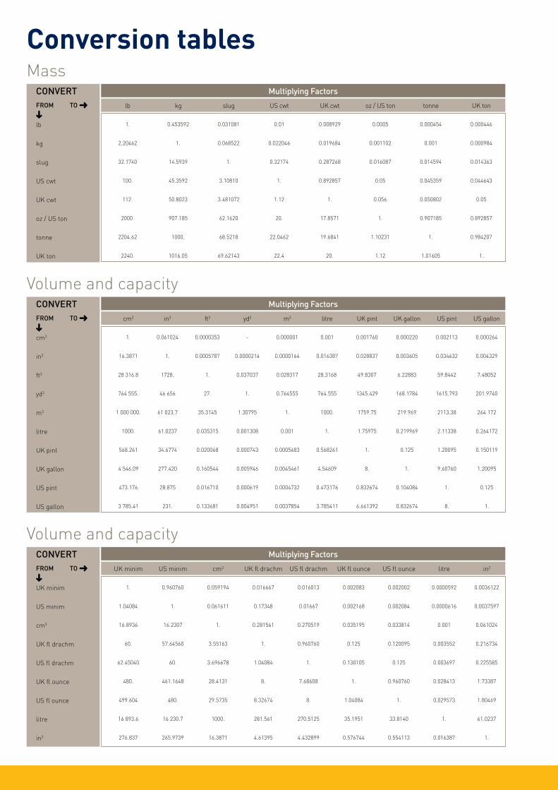
Conversion tables
lb kg slug US cwt UK cwt oz / US ton tonne UK ton
lb
kg
slug
US cwt
UK cwt
oz / US ton
tonne
UK ton
1. 0.453592 0.031081 0.01 0.008929 0.0005 0.000454 0.000446
2.20462 1. 0.068522 0.022046 0.019684 0.001102 0.001 0.000984
32.1740 14.5939 1. 0.32174 0.287268 0.016087 0.014594 0.014363
100. 45.3592 3.10810 1. 0.892857 0.05 0.045359 0.044643
112. 50.8023 3.481072 1.12 1. 0.056 0.050802 0.05
2000. 907.185 62.1620 20. 17.8571 1. 0.907185 0.892857
2204.62 1000. 68.5218 22.0462 19.6841 1.10231 1. 0.984207
2240. 1016.05 69.62143 22.4 20. 1.12 1.01605 1.
Multiplying FactorsCONVERTFROM TO ➜➜
Mass
cm3 in3 ft3 yd3 m3 litre UK pint UK gallon US pint US gallon
cm3
in3
ft3
yd3
m3
litre
UK pint
UK gallon
US pint
US gallon
1. 0.061024 0.0000353 - 0.000001 0.001 0.001760 0.000220 0.002113 0.000264
16.3871 1. 0.0005787 0.0000214 0.0000164 0.016387 0.028837 0.003605 0.034632 0.004329
28 316.8 1728. 1. 0.037037 0.028317 28.3168 49.8307 6.22883 59.8442 7.48052
764 555. 46 656 27. 1. 0.764555 764.555 1345.429 168.1784 1615.793 201.9740
1 000 000. 61 023.7 35.3145 1.30795 1. 1000. 1759.75 219.969 2113.38 264.172
1000. 61.0237 0.035315 0.001308 0.001 1. 1.75975 0.219969 2.11338 0.264172
568.261 34.6774 0.020068 0.000743 0.0005683 0.568261 1. 0.125 1.20095 0.150119
4 546.09 277.420 0.160544 0.005946 0.0045461 4.54609 8. 1. 9.60760 1.20095
473.176 28.875 0.016710 0.000619 0.0004732 0.473176 0.832674 0.104084 1. 0.125
3 785.41 231. 0.133681 0.004951 0.0037854 3.785411 6.661392 0.832674 8. 1.
Multiplying FactorsCONVERTFROM TO ➜➜
Volume and capacity
UK minim US minim cm3 UK fl drachm US fl drachm UK fl ounce US fl ounce litre in3
UK minim
US minim
cm3
UK fl drachm
US fl drachm
UK fl ounce
US fl ounce
litre
in3
1. 0.960760 0.059194 0.016667 0.016013 0.002083 0.002002 0.0000592 0.0036122
1.04084 1. 0.061611 0.17348 0.01667 0.002168 0.002084 0.0000616 0.0037597
16.8936 16.2307 1. 0.281561 0.270519 0.035195 0.033814 0.001 0.061024
60. 57.64560 3.55163 1. 0.960760 0.125 0.120095 0.003552 0.216734
62.45040 60. 3.696678 1.04084 1. 0.130105 0.125 0.003697 0.225585
480. 461.1648 28.4131 8. 7.68608 1. 0.960760 0.028413 1.73387
499.604 480. 29.5735 8.32674 8. 1.04084 1. 0.029573 1.80469
16 893.6 16 230.7 1000. 281.561 270.5125 35.1951 33.8140 1. 61.0237
276.837 265.9739 16.3871 4.61395 4.432899 0.576744 0.554113 0.016387 1.
Multiplying FactorsCONVERTFROM TO ➜➜
Volume and capacity

Chemical compatibility
NC = Not Compatible
LC = Limited Compatibility
C = Compatible
- = No Data
NC = Not CompatibileLC = Limited Compatibility C = Compatible - = No Data
Ace
tic
acid
3.5
N
Ace
tic
acid
8.7
5N
Ace
tic
acid
con
c. 1
7.5N
Ace
tone
Ace
toni
trile
Aci
dbri
te 4
(Div
erse
y) 3
.0%
v/v
Am
mon
ium
Hyd
roxi
de 8
N
Am
mon
ium
Oxa
late
0.0
7N
Am
yl A
ceta
te
Aqu
eous
Am
mon
ia 1
5.5N
Ben
zyl A
lcoh
ol
Ben
zyal
koni
um C
hlor
ide
0.1%
Bor
ic a
cid,
sat
urat
ed
But
an-1
-ol
But
an-2
-ol
Car
bon
Tetr
achl
orid
e
Chl
orof
orm
Cyc
lohe
xane
1,4
- D
ioxa
ne
Div
erfl
ow (D
iver
sey)
3%
v/v
Biopharmaceutical
PROCLEAR GF C C C C LC C C C LC LC NC C C C C NC NC NC LC NC
PROCLEAR GP - C C C LC C C C LC LC NC C C C C NC NC NC LC NC
PROCLEAR PP C C C C C C C C C C NC C C C C NC NC NC C C
PROPOR BR C - - NC - - LC - LC LC - - - C C - NC - - C
PROPOR HC C - - NC - - LC - LC LC - - - C C - NC - - C
PROPOR MR C - - NC - - LC - LC LC - - - C C - NC - - C
PROPOR SG C - - NC - - LC - LC LC - - - C C - NC - - C
Pharmaceutical
HIGH FLOW PREPOR GFA C C C C LC C C C LC LC NC C C C C NC NC NC LC NC
PEPLYN AIR C C C C C C C C C C NC C C C C NC NC NC C C
HIGH FLOW BIO-X C C C C C - C C C C C C C C C C C C C -
HIGH FLOW TETPOR II C C C C C - C C C C C C C LC C C C - C -
HIGH FLOW TETPOR H.T. C C C C C - C C C LC C C C LC C C C - C -
TETPOR AIR C C C C C - C C C C C C C NC C NC NC LC C -
Bag Filters (Polypropylene) C C C C C - C C C C - - - C C NC NC NC - -
PEPLYN PLUS C C C C C C C C C C NC C C C C NC NC NC C C
PROSTEEL A & N C C C C C C C C C C C C C C C C C C C C
SPUNFLOW QE C C C C C - C C C C - - - C C NC NC NC - -
TEXFLOW C C C C C - C C C C - - - C C NC NC NC - -
PROPOR LR C - - NC - - LC - LC LC - - - C C - NC - - C
TETPOR HP C C C C C - C C C C C C C NC C NC NC LC C -
TETPOR LIQUID C C C C C - C C C C C C C NC C NC NC LC C -
TETPOR PLUS C C C C C - C C C C C C C NC C NC NC LC C -
EPDM C LC LC C NC C C C NC C C C C C LC NC NC NC NC C
SILICONE C LC NC NC NC C C C NC C C C C C C C LC NC NC C
VITON C NC NC NC NC C C C LC C C C C C C NC NC NC NC LC

NC = Not CompatibileLC = Limited Compatibility C = Compatible - = No Data
Div
erse
y 21
2G 0
.6%
v/v
Div
osan
For
te 0
.5%
v/v
Div
osan
XT
1% v
/v
Etha
nol
Etha
nol 4
5%
Ethy
l Ace
tate
Form
alde
hyde
0.3
%
Form
alde
hyde
37%
Form
ic a
cid
conc
.
Gly
cero
l
Hex
ane
Hyd
roch
lori
c ac
id 1
N
Hyd
roch
lori
c ac
id c
onc.
Hyd
roch
lori
c ac
id c
onc.
13%
Hyd
roge
n P
erox
ide
Hyd
roge
n P
erox
ide
10%
Vol
ume
Hyd
roge
n P
erox
ide
100%
Vol
ume
Met
hano
l
Met
hyl-
Iso-
But
ylke
tone
Met
hyle
ne C
hlor
ide
@ 4
0°C
(104
°F)
Biopharmaceutical
PROCLEAR GF C C C C C LC C C NC C - C NC - - C C C C LC
PROCLEAR GP C C C C C LC C C NC C - C NC - - C C C C LC
PROCLEAR PP C C C C C LC C C C C NC C C - C C C C C LC
PROPOR BR - C - C C NC C - - C - C - - - C - C NC -
PROPOR HC - C - C C NC C - - C - C - - - C - C NC -
PROPOR MR - C - C C NC C - - C - C - - - C - C NC -
PROPOR SG - C - C C NC C - - C - C - - - C - C NC -
Pharmaceutical
HIGH FLOW PREPOR GFA C C C C C LC C C NC C - C NC - - C C C C LC
PEPLYN AIR C C C C C LC C C C C NC C C - C C C C C LC
HIGH FLOW BIO-X - - - C - LC C C C C C - - C C - - C C -
HIGH FLOW TETPOR II - - - C - LC C C C C C - - C - - C C C -
HIGH FLOW TETPOR H.T. - - - - - LC C C C C C - - C - - C C C -
TETPOR AIR - - - C C LC C C C C - C C - - C C C C -
Bag Filters (Polypropylene) - - - C C LC - - C C LC LC NC - - LC LC C C NC
PEPLYN PLUS C C C C C LC C C C C NC C C - C C C C C LC
PROSTEEL A & N C C C C C C C C C C C LC - - C C C C C C
SPUNFLOW QE - - - C C LC C C NC C - C C C C C C LC
TEXFLOW - - - C C LC - - C C NC C C - C C C C C LC
PROPOR LR - C - C C NC C - - C - C - - - C - C NC -
TETPOR HP - - - C C LC C C C C - C C - - C C C C -
TETPOR LIQUID - - - C C LC C C C C - C C - - C C C C -
TETPOR PLUS - - - C C LC C C C C - C C - - C C C C -
EPDM C C C C C C C C C C NC C NC NC C C C C NC -
SILICONE C C C C C NC C C NC C NC C NC NC C C C NC NC -
VITON C C C LC C LC C C NC C NC C NC NC C C C C LC -
Chemical compatibility

Chemical compatibility
NC = Not CompatibileLC = Limited Compatibility C = Compatible - = No Data
Nit
ric
acid
2N
14.
4%
Nit
ric
acid
15.
8N
Ozo
ne
Par
affin
Yel
low
Pen
tane
Per
acet
ic a
cide
0.5
% (1
0 w
k te
st)
Per
acet
ic a
cid
4%
Per
chlo
roet
hyle
ne
Pet
role
um s
piri
ts
Phe
nol (
aq) (
0.5N
)
Phe
nol 5
%
Phe
nol 0
.25%
Pol
yeth
ylen
e G
lyco
l 600
Pol
ygly
col 2
000-
E
Pot
assi
um D
ichr
omat
e 0.
1N
Pot
assi
um Io
dine
0.6
N
Pot
assi
um H
ydro
xide
10N
Pot
assi
um P
erm
anga
nate
0.1
N
Pro
pan-
1-ol
Pro
pan-
2-ol
Biopharmaceutical
PROCLEAR GF NC NC NC LC LC - C NC NC - C C NC - C C NC NC NC NC
PROCLEAR GP NC NC NC LC - - C NC - - - - NC - - - C C C C
PROCLEAR PP C C - C LC - C - NC - C C LC - C C C C C C
PROPOR BR C - NC - - - C NC - - - - NC - - - LC C C C
PROPOR HC C - NC - - - C NC - - - - NC - - - LC C C C
PROPOR MR C - NC - - - C NC - - - - NC - - - LC C C C
PROPOR SG C - NC - - - C NC - - - - NC - - - LC C C C
Pharmaceutical
HIGH FLOW PREPOR GFA C NC - LC LC - C - NC - C C NC - C C NC NC NC NC
PEPLYN AIR C C - C LC - C - NC - C C C - C C C C C C
HIGH FLOW BIO-X C C - LC C - C - - C - - LC - C C C C C C
HIGH FLOW TETPOR II C C - C - C C - C NC - - C - C C C C C C
HIGH FLOW TETPOR H.T. C NC - C - C C - C - - - C - C C C LC C C
TETPOR AIR C C - C LC - C - LC - C C - - C C C C C C
Bag Filters (Polypropylene) NC C NC C LC - - - NC - C C C - C C C C C C
PEPLYN PLUS C C - C LC - C - NC - C C C - C C C C C C
PROSTEEL A & N C C NC C C C C C C C C C C C C C C C C C
SPUNFLOW QE C C - C LC - - - NC - C C C - C C C C C C
TEXFLOW C C - C LC - - - NC - C C C - C C C C C C
PROPOR LR C - NC - - - C NC - - - - NC - - - LC C C C
TETPOR HP C C - C LC - C - LC - C C - - C C C C C C
TETPOR LIQUID C C - C LC - C - LC - C C - - C C C C C C
TETPOR PLUS C C - C LC - C - LC - C C - - C C C C C C
EPDM LC NC - NC NC C C - NC - C C - C C C C C C C
SILICONE C NC - C C C C - C - C C - C C C C C C C
VITON C NC - NC NC C C - NC - C C - C C C C C LC LC

NC = Not CompatibileLC = Limited Compatibility C = Compatible - = No Data
Pro
pan-
2-ol
, 60:
40 H
2O
Pyr
idin
e
Sodi
um C
hlor
ide
0.5N
Salin
e La
ctos
e B
roth
Sodi
um H
ydro
xide
1N
4%
Sodi
um H
ydro
xide
7N
28%
Sodi
um H
ypoc
hlor
ite (1
4% F
ree
Cl 2)
Sodi
um th
iosu
lpha
te
Sulp
huri
c ac
id 1
N
Sulp
huri
c ac
id c
onc.
Sulp
huri
c ac
id
Tolu
ene
1,1,
1 Tr
ichl
oroe
than
e
1,1,
2 Tr
ichl
oroe
than
e
Tric
hlor
oece
tic
Aci
d 80
%
Tric
hlor
oace
tic
Aci
d 5N
Xyle
ne
Biopharmaceutical
PROCLEAR GF NC NC C C C NC C C LC LC - NC - NC LC - NC
PROCLEAR GP C NC C C C NC C C C NC NC NC - NC LC - NC
PROCLEAR PP C C C C C C C C C LC - NC - LC C - NC
PROPOR BR C NC C C C NC C - C NC NC NC - NC - - LC
PROPOR HC C NC C C C NC C - C NC NC NC - NC - - LC
PROPOR MR C NC C C C NC C - C NC NC NC - NC - - LC
PROPOR SG C NC C C C NC C - C NC NC NC - NC - - LC
Pharmaceutical
HIGH FLOW PREPOR GFA NC NC C C C NC C C LC LC - NC - LC LC - NC
PEPLYN AIR C C C C C C C C C LC - NC - LC C - NC
HIGH FLOW BIO-X C C C C NC NC C C C NC - NC - C - C LC
HIGH FLOW TETPOR II C C C C C C C C C LC - NC - C - C LC
HIGH FLOW TETPOR H.T. C C C C C C C C C NC - NC - LC - C LC
TETPOR AIR C C C C C C C C - LC - - - LC C - NC
Bag Filters (Polypropylene) - C C - - C - C C LC - NC - LC C - NC
PEPLYN PLUS C C C C C C C C C LC - NC - LC C - NC
PROSTEEL A & N C C C C C C C C C C C C C C C C C
SPUNFLOW QE - C C - - C - C C LC - NC - LC C - NC
TEXFLOW - C C - - C - C C LC - NC - LC C - NC
PROPOR LR C NC C C C NC C - C NC NC NC - NC - - LC
TETPOR HP C C C C C C C C - LC - - - LC C - NC
TETPOR LIQUID C C C C C C C C - LC - - - LC C - NC
TETPOR PLUS C C C C C C C C - LC - - - LC C - NC
EPDM C C C C C C C C C - - NC - NC NC - C
SILICONE C NC C C C C C C C - - LC - LC LC - LC
VITON C C C C C LC C C C - - NC - LC NC - NC
The chemicals are arranged in alphabetical order using their most common or trade names. If the chemical in question does not appear to be listed, it may be found elsewhere in the table under a pseudonym, in particular its IUPAC11 name.
With regard to compatibility:•Any product that has
Limited Compatibility (LC) at ambient temperatures should not be used at a higher temperature.•The list of compatibilities
does not take into account any synergistic effects of more than one chemical present in the solution to be filtered.•Test Conditions - 72
hours at ambient temperature and pressure, unless otherwise stated.•Contact Parker
domnick hunter for confirmation of compatibility with specific operating conditions.
Chemical compatibility
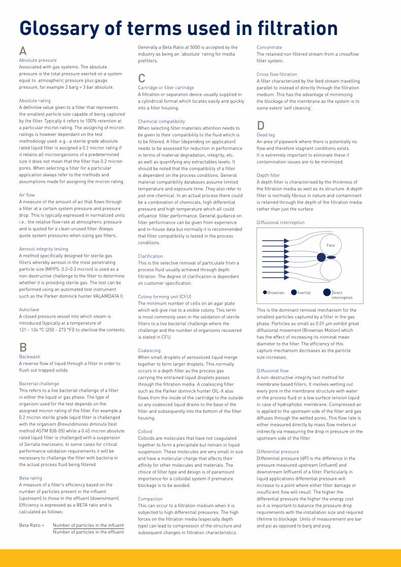
Glossary of terms used in filtrationAAbsolute pressureAssociated with gas systems. The absolute pressure is the total pressure exerted on a system equal to atmospheric pressure plus gauge pressure, for example 2 barg = 3 bar absolute.
Absolute ratingA definitive value given to a filter that represents the smallest particle size capable of being captured by the filter. Typically it refers to 100% retention at a particular micron rating. The assigning of micron ratings is however dependant on the test methodology used. e.g.: a sterile grade absolute rated liquid filter is assigned a 0.2 micron rating if it retains all microorganisms of a predetermined size it does not mean that the filter has 0.2 micron pores. When selecting a filter for a particular application always refer to the methods and assumptions made for assigning the micron rating.
Air flowA measure of the amount of air that flows through a filter at a certain system pressure and pressure drop. This is typically expressed in normalized units i.e.: the relative flow rate at atmospheric pressure and is quoted for a clean unused filter. Always quote system pressures when sizing gas filters.
Aerosol integrity testingA method specifically designed for sterile gas filters whereby aerosol in the most penetrating particle size (MPPS: 0.2–0.3 micron) is used as a non-destructive challenge to the filter to determine whether it is providing sterile gas. The test can be performed using an automated test instrument such as the Parker domnick hunter VALAIRDATA II.
AutoclaveA closed pressure vessel into which steam is introduced (typically at a temperature of 121 - 134 °C (250 - 273 °F)) to sterilise the contents.
BBackwashA reverse flow of liquid through a filter in order to flush out trapped solids.
Bacterial challengeThis refers to a live bacterial challenge of a filter in either the liquid or gas phase. The type of organism used for the test depends on the assigned micron rating of the filter. For example a 0.2 micron sterile grade liquid filter is challenged with the organism Brevundimonas diminuta (test method ASTM 838-05) while a 0.45 micron absolute rated liquid filter is challenged with a suspension of Serratia marcesens. In some cases for critical performance validation requirements it will be necessary to challenge the filter with bacteria in the actual process fluid being filtered.
Beta ratingA measure of a filter’s efficiency based on the number of particles present in the influent (upstream) to those in the effluent (downstream). Efficiency is expressed as a BETA ratio and is calculated as follows:
Beta Ratio = Number of particles in the influent Number of particles in the effluent
Generally a Beta Ratio at 5000 is accepted by the industry as being an ‘absolute’ rating for media prefilters.
CCartridge or filter cartridgeA filtration or separation device usually supplied in a cylindrical format which locates easily and quickly into a filter housing.
Chemical compatibilityWhen selecting filter materials attention needs to be given to their compatibility to the fluid which is to be filtered. A filter (depending on application) needs to be assessed for reduction in performance in terms of material degradation, integrity, etc. as well as quantifying any extractables levels. It should be noted that the compatibility of a filter is dependent on the process conditions. General material compatibility databases assume limited temperature and exposure time. They also refer to just one chemical. In an actual process there could be a combination of chemicals, high differential pressure and high temperature which all could influence filter performance. General guidance on filter performance can be given from experience and in-house data but normally it is recommended that filter compatibility is tested in the process conditions.
ClarificationThis is the selective removal of particulate from a process fluid usually achieved through depth filtration. The degree of clarification is dependant on customer specification.
Colony forming unit (CFU)The minimum number of cells on an agar plate which will give rise to a visible colony. This term is most commonly seen in the validation of sterile filters to a live bacterial challenge where the challenge and the number of organisms recovered is stated in CFU.
Coalescing When small droplets of aerosolized liquid merge together to form larger droplets. This normally occurs in a depth filter as the process gas carrying the entrained liquid droplets passes through the filtration media. A coalescing filter such as the Parker domnick hunter OIL-X also flows from the inside of the cartridge to the outside so any coalesced liquid drains to the base of the filter and subsequently into the bottom of the filter housing.
ColloidColloids are molecules that have not coagulated together to form a precipitate but remain in liquid suspension. These molecules are very small in size and have a molecular charge that affects their affinity for other molecules and materials. The choice of filter type and design is of paramount importance for a colloidal system if premature blockage is to be avoided.
CompactionThis can occur to a filtration medium when it is subjected to high differential pressures. The high forces on the filtration media (especially depth type) can lead to compression of the structure and subsequent changes in filtration characteristics.
ConcentrateThe retained non filtered stream from a crossflow filter system.
Cross flow filtrationA filter characterized by the feed stream travelling parallel to instead of directly through the filtration medium. This has the advantage of minimizing the blockage of the membrane as the system is to some extent ‘self cleaning’.
DDead legAn area of pipework where there is potentially no flow and therefore stagnant conditions exists. It is extremely important to eliminate these if contamination issues are to be minimized.
Depth filterA depth filter is characterised by the thickness of the filtration media as well as its structure. A depth filter is normally fibrous in nature and contaminant is retained through the depth of the filtration media rather than just the surface.
Diffusional interception
This is the dominant removal mechanism for the smallest particles captured by a filter in the gas phase. Particles as small as 0.01 µm exhibit great diffusional movement (Brownian Motion) which has the effect of increasing its nominal mean diameter to the filter. The efficiency of this capture mechanism decreases as the particle size increases.
Diffusional flowA non-destructive integrity test method for membrane based filters. It involves wetting out every pore in the membrane structure with water or the process fluid or a low surface tension liquid in case of hydrophobic membrane. Compressed air is applied to the upstream side of the filter and gas diffuses through the wetted pores. This flow rate is either measured directly by mass flow meters or indirectly via measuring the drop in pressure on the upstream side of the filter.
Differential pressureDifferential pressure (dP) is the difference in the pressure measured upstream (influent) and downstream (effluent) of a filter. Particularly in liquid applications differential pressure will increase to a point where either filter damage or insufficient flow will result. The higher the differential pressure the higher the energy cost so it is important to balance the pressure drop requirements with the installation size and required lifetime to blockage. Units of measurement are bar and psi as opposed to barg and psig.
Fibre
Brownian Inertial Directinterception

Glossary of terms used in filtrationEEffective filtration area (EFA)This is the area of filtration material available for filtration.
EffluentThe fluid which has passed through a filter.
ExtractablesWhen a filter is in contact with the process fluid, chemical components may leach from the materials of construction and deposited in the filtrate. The levels of non-volatile extractables for a limited number of fluids are quoted in the filter validation guide. The level of extractables is dependent on the process conditions. Filtration of solvents, high temperature fluids and steam sterilization are three areas where extractables can increase.
FFilter (noun) / filter cartridge / cartridgeAn apparatus which performs filtration.
Filter (verb)To pass a fluid or gas through a porous medium in order to remove solid particles.
Filter efficiencyFilter efficiency is a measure of the percentage of particles that are removed from the fluid by the filter. Typically these are given in terms of the % removal for a certain size of particle. A filter efficiency may also be given across a range of particle sizes . For a number of gas applications the efficiency of a filter may be quoted in relation to the filters ability to remove particles at the most penetrating particle size (MPPS) of 0.2-0.3 micron. Always ensure filter efficiency is matched to the requirements of the process.
Filterability indices (FI) and Vmax This is an indication of a filters capacity to process certain fluids. It generally gives a measure of the rate of blockage of a filter as well as the theoretical maximum throughput. The time required to flow two consecutive 200 ml fluid samples is recorded and the filterability indices are calculated from the results. The two formulae used are as follows:
(Vmax) = 400 + 400T1
(T2 - 2T1)
FI = (T2 - 2T1)
T1 = Time to filter first 200 mlT2 = Time to filter second 200 ml
It should be noted that these methods give a general indication of performance and are often more useful in comparative performance measurement between different filter types.
FiltrateAnother name for effluent.
Filter sterilizationSterilization is the act of making an organism barren or infertile (unable to reproduce). The sterilization of a filter can be achieved by a number of methods including dry heat, steam, ethylene oxide, hydrogen peroxide or irradiation. The method chosen depends on the process and
the materials of construction of the filter but by far the most widely used is that of steam, either in an autoclave or via steam-in-place (SIP).
FluxThe rate of fluid flow (gas or liquid) when expressed in terms of flow per unit area of the filter that removes the contaminants from the fluid stream. It can apply to both depth and membrane media.
GGauge pressureThe pressure of a system measured by a gauge, which excludes atmospheric pressure, for example 1 bar atmosphere (or 1 bar absolute) = 0 barg.
HHousingAn enclosure for a filter element, typically rated for pressure, that directs the fluid through the filter.
HydrophilicHydrophilicity is the ability of a filtration media to ‘wet out’, that is, for the porous structure to be completed filled with the liquid being filtered. This is an important characteristic as incomplete wetting of the structure can lead to a reduction in flow capacity and problems with integrity testing. All liquid filters are ‘hydrophilic’ apart from those that may have been selected for use with aggressive solvents. These filters are typically based on a fluoropolymer and their structure needs to be wetted with a low surface tension liquid such as isopropyl alcohol. Once the structure has been wet, the filter will process aqueous solutions without a problem.
IInertial impactionThis is a removal mechanism for particles captured by a filter in the gas phase. The particles follow the streamlines of gas between the filter fibres and membrane pores. Due to their mass the inertia of the particle will cause it to move out of the streamline and attach itself to a fibre or pore wall. The effect of this capture mechanism increases with particle size / mass.
InfluentThe fluid entering the filter system.
In vitroIn an unnatural position e.g. outside the body “ In vitro” is Latin for “in glass” an experiment performed without the involvement of a whole, living organism.
In vivoThe testing of a substance or experimentation in or using a living, whole organism.
LLog reduction value (LRV)This is a measurement of a filters removal efficiency for a specific contaminant. It is normally associated with the bacterial retention of a filter. The LRV is :
Log10 Number of bacteria in the influent Number of bacteria in the effluente.g. (Log10 1 x 10¹⁰
) = LRV of >10 1
It is always expressed as > (greater than) as 1 has to be used for the effluent even if there are no organisms present. This can also be expressed as a 10 log reduction or a titre reduction of 1010.
MMedium (Media)This is the component of the filter that removes the contaminants from the fluid stream. Also commonly referring to depth - type materials, in its more generic sense a filter medium / media can refer to either depth or membrane filter materials.
MicrofiltrationMicrofiltration is the process of removing particles from a liquid or gas by passing it through a porous medium. It generally involves removing particles between the sizes of 10 and 0.04 micron in liquids, and down to 0.01 micron in gases.
Micron (micrometer)Designated by the Greek letter µ a micron is 10-
3mm (millimeters) or 104 (Angstroms) or 0.00003937 inch. For a perspective on this size a human hair is approximately 70 microns thick and the limit of resolution of the naked eye is around 40 microns.
MembraneA membrane is a thin, porous film typically between 30 and 150 micron in thickness. It has of tens of millions of pores / cm2 through which the process fluid runs. The nature of the pore structure is determined by the manufacturing method. Solvent cast membranes such as Polyethersulphone (PES) and Mixed Esters of Cellulose (MEC) have a defined pore structure which can be asymmetric whilst membrane such as Polytetrafluoroethylene (PTFE) which is manufactured by ‘stretching’ have a fibrous appearance and a less defined pore structure.
NNanofiltrationFiltration that removes both particles and small dissolved molecules and ions. Finer than ultrafiltration, not as fine as Reverse Osmosis.
NanometerA nanometer is 10-9 meters
Nominal filter ratingThis rating is often quoted within the filtration industry but great care should be taken in ensuring the efficiency and test methodologies are completely understood. A 5 micron nominal filter could be 99% retentive at 5 micron, another could be 80%. It can be very misleading to compare the performance of filters on nominal ratings. When selecting a filter the duty required should be
Fibre
Brownian Inertial Directinterception

Glossary of terms used in filtrationcompared to the individual performance characteristics of filter. Parker domnick hunter has the experience to help select the most appropriate filter for the application.
OOleophobicOleophobic membranes and depth media have the capability to repel fluids such as oil and lubricants. This phenomena is used in some of the new generation oil coalescing filters.
OxidationThis refers to the degradation of materials in the presence of oxygen and high temperature. It is normally associated with high temperature gas systems where the combination of steam sterilization can lead to the onset of oxidation of polypropylene filtration components in as little as 3 months. For applications where continuous (1 year and above) exposure to high temperature is required the use of a special product with oxidation resistant filtration support materials such as the HIGH FLOW TETPOR H.T. is recommended.
Oxidation can also occur on filters used in ozonated water systems. In these instances careful selection of filter components is required.
PPleating Filtration media can be pleated or corregated to maximize the filtration area. By pleating filtration media it is possible to fit a large EFA in a relatively small cartridge volume.
Voids volume (porosity)This is a measurement of the free space in a filtration media. The more free space the less the resistance to flow. Typical values for a membrane are in the region of 50 – 80% and for depth type media between 60 - 95%.
Pressure decayA non-destructive integrity test method for membrane based filters. It involves wetting out every pore in the membrane structure with water or the process fluid or a low surface tension liquid in case of hydrophobic membrane. Compressed air is applied to the upstream side of the filter and gas diffuses through the wetted pores. This causes a pressure drop in the upstream side of the filter known as the pressure decay. The maximum allowable pressure decay for a filter is dependant on the upstream volume and therefore must be known.
Pressure Decay (mbar /min) =
Diffusional Flow (ml / min) Upstream Vol (l)
PyrogenicityPyrogenicity is the tendency of a substance to raise body temperature when injected into the body. Filtration materials that come in contact with injectable liquids must meet pyrogenicity standards and be classified as non-pyrogenic. Pyrogenicity can be determined by such standard tests as the Limulus Amoebocyte Lysate (LAL) test.
PermeateSynonymous with filtrate.
RRegeneration When a filter becomes blocked with protein based material it may be possible to regenerate, or clean the filter, so improving overall lifetime.
Reverse jettingThe application of high pressure compressed gas to the inside of a filter to release powder collected on its surface.
Reverse osmosisForcing a liquid through a non-porous membrane, removing particles, along with dissolved molecules and ions. Reverse osmosis is the finest form of membrane separation and is used to desalinate water for drinking, and in the preparation of ultrapure water for various industries.
SSanitizationReduction not elimination of a microbial population to render a fluid/system free from spoilage organisms and increase shelf-life of products.
Sedimentation The process by which suspended solid particles in a liquid phase gravitate downwards. Eventually they will settle on the bottom of the holding tank, pipework etc. The rate of sedimentation is governed by particle mass and fluid velocity.
SeparationSeparation is the process of dividing a fluid stream (either liquid or gas) into separate components. This can include separation of two phases (liquid from gas), separation of soluble impurities (known as purification) or solids from a fluid (filtration). The products of a separation can themselves be separated further in many cases.
Silt density index (SDI)This is another measure of the rate of blockage and is typically used when the system is relatively clean and the difference between T400 and T200 (see Filterability Indices) is so small that large inaccuracies can occur. The SDI uses the time taken for two 500 ml samples of fluid to pass though a 47 mm diameter 0.45 µm disc. There is typically a 15 minute gap between the two samples being taken.
Size exclusionThis is a removal mechanism for particles captured by a filter in either the liquid or gas phase. It applies to particles that are physically too large to pass through the filter structure. The mechanism is not affected by flow rate unless pressure drops cause deformation of the particle.
SoluteA solid which is dissolved in a solvent. For instance, the salt in salt water is a solute.
Solvent A liquid substance capable of dissolving other substances. The solvent does not change its state in forming a solution.
Stabilization This is the reduction in microbial loading in a fluid system and is generally associated with the beverage industry where partial rather than complete removal of spoilage organisms may be required to extend shelf-life. SterilizationIn terms of filtration this means the elimination of all living microorganisms from the influent stream.
SurfactantAcronym for a surface active agent. In filtration it is also sometimes called a wetting agent. If a filter is being used to filter aqueous solutions and incomplete wetting of the membrane pore structure is encountered a ‘wetting agent’ may be added to the membrane surface by flowing a quantity of surfactant through the filter. However, the use of a wetting agent is not desirable, especially in a pharmaceutical environment, as there is also the possibility of the surfactant leaching from the filter into the filtrate during processing or steam sterilization, etc.
TThermal stabilityThis is most important during sterilization of the filter. The majority of cartridge and disposable type filters are manufactured from polymers such as polypropylene and nylon. During sterilization the components of the filter expand and contract putting great strain on the device. The filter performance with respect to steam sterilization should be matched closely to the requirements of the process. It should be noted that some filter configurations cannot be in-situ steam sterilized but can only be autoclaved.
Titre reductionSee LRV.
TurbidityThis is a measurement of the amount of suspended particles in a fluid and is effectively a clarity index. It is measured in NTU ( Nephelometric Turbidity Units).
Fibre
Brownian Inertial Directinterception

Glossary of terms used in filtrationUUnloadingThe release of contaminants which had initially been captured by a filter. This is most likely to occur in filtration systems with are subjected to high pressure pulses such as high capacity filling lines.
UltrafiltrationFiltration of a liquid that separates suspended or dissolved substances based on their molecular weight or size. Ultrafiltration generally refers to separating everything larger than a large molecule. Compare to microfiltration, nanofiltration, reverse osmosis.
VViscosityViscosity is a measurement of the resistance to flow of a fluid. The more viscous the fluid, the greater the time required to filter. Viscosity will in general reduce with an increase in temperature. This is why very viscous solutions such as glucose are heated prior to filtration.
VmaxSee Filterability Indices.
WWater flowMeasure of the amount of water that flows through a filter. Related to the degree of contamination, differential pressure, total porosity, and filter area (ASTM:F317-72). Expressed in the membrane industry in units of millilitres / minute / square centimetre.
Water IntrusionA non-destructive integrity test method specifically designed for hydrophobic filters. It involves filling the upstream volume of a filter housing with water and applying a pressure, typically in the order 2.5 barg. As the membrane is hydrophobic the bulk water will not pass through. However, due to the difference in pressure between the upstream and downstream side of the filter there is a net loss of water from the upstream side due to evaporation and the slight penetration of water into the pore structure. This loss of water results in a pressure drop which is displayed as either a water intrusion value or a water flow value. The water intrusion is the measure of the increase in compressible gas volume expressed at atmospheric pressure and the water flow equates to the volume of water lost from the system.
Water flow = Water Intrusion / Absolute test pressure.


© 2014 Parker Hannifin Corporation. All rights reserved.
CAT_LifeSciences_02/14 Rev. 1D
Parker Hannifin Manufacturing Ltddomnick hunterProcess Filtration - EuropeDurham RoadBirtley, Co. DurhamDH3 2SF, Englandphone +44 (0)191 4105121fax +44 (0)191 4105312email: [email protected]/dhpharma
Parker Hannifin Corporationdomnick hunterProcess Filtration - North America2340 Eastman Avenue,Oxnard, California, USA 93030toll free: 877 784 2234phone: +1 805 604 3400fax: +1 805 604 3401email: [email protected]/dhpharma
Europe, Middle East, AfricaAE – United Arab Emirates, Dubai Tel: +971 4 8127100 [email protected]
AT – Austria, Wiener Neustadt Tel: +43 (0)2622 23501-0 [email protected]
AT – Eastern Europe, Wiener Neustadt Tel: +43 (0)2622 23501 900 [email protected]
AZ – Azerbaijan, Baku Tel: +994 50 2233 458 [email protected]
BE/LU – Belgium, Nivelles Tel: +32 (0)67 280 900 [email protected]
BG – Bulgaria, Sofia Tel: +359 2 980 1344 [email protected]
BY – Belarus, Minsk Tel: +375 17 209 9399 [email protected]
CH – Switzerland, Etoy Tel: +41 (0)21 821 87 00 [email protected]
CZ – Czech Republic, Klecany Tel: +420 284 083 111 [email protected]
DE – Germany, Kaarst Tel: +49 (0)2131 4016 0 [email protected]
DK – Denmark, Ballerup Tel: +45 43 56 04 00 [email protected]
ES – Spain, Madrid Tel: +34 902 330 001 [email protected]
FI – Finland, Vantaa Tel: +358 (0)20 753 2500 [email protected]
FR – France, Contamine s/Arve Tel: +33 (0)4 50 25 80 25 [email protected]
GR – Greece, Athens Tel: +30 210 933 6450 [email protected]
HU – Hungary, Budaörs Tel: +36 23 885 470 [email protected]
IE – Ireland, Dublin Tel: +353 (0)1 466 6370 [email protected]
IT – Italy, Corsico (MI) Tel: +39 02 45 19 21 [email protected]
KZ – Kazakhstan, Almaty Tel: +7 7273 561 000 [email protected]
NL – The Netherlands, Oldenzaal Tel: +31 (0)541 585 000 [email protected]
NO – Norway, Asker Tel: +47 66 75 34 00 [email protected]
PL – Poland, Warsaw Tel: +48 (0)22 573 24 00 [email protected]
PT – Portugal, Leca da Palmeira Tel: +351 22 999 7360 [email protected]
RO – Romania, Bucharest Tel: +40 21 252 1382 [email protected]
RU – Russia, Moscow Tel: +7 495 645-2156 [email protected]
SE – Sweden, Spånga Tel: +46 (0)8 59 79 50 00 [email protected]
SK – Slovakia, Banská Bystrica Tel: +421 484 162 252 [email protected]
SL – Slovenia, Novo Mesto Tel: +386 7 337 6650 [email protected]
TR – Turkey, Istanbul Tel: +90 216 4997081 [email protected]
UA – Ukraine, Kiev Tel +380 44 494 2731 [email protected]
UK – United Kingdom, Warwick Tel: +44 (0)1926 317 878 [email protected]
ZA – South Africa, Kempton Park Tel: +27 (0)11 961 0700 [email protected]
North AmericaCA – Canada, Milton, Ontario Tel: +1 905 693 3000
US – USA, Cleveland Tel: +1 216 896 3000
Asia PacificAU – Australia, Castle Hill Tel: +61 (0)2-9634 7777
CN – China, Shanghai Tel: +86 21 2899 5000
HK – Hong Kong Tel: +852 2428 8008
IN – India, Mumbai Tel: +91 22 6513 7081-85
JP – Japan, Tokyo Tel: +81 (0)3 6408 3901
KR – South Korea, Seoul Tel: +82 2 559 0400
MY – Malaysia, Shah Alam Tel: +60 3 7849 0800
NZ – New Zealand, Mt Wellington Tel: +64 9 574 1744
SG – Singapore Tel: +65 6887 6300
TH – Thailand, Bangkok Tel: +662 186 7000-99
TW – Taiwan, Taipei Tel: +886 2 2298 8987
South AmericaAR – Argentina, Buenos Aires Tel: +54 3327 44 4129
BR – Brazil, Sao Jose dos Campos Tel: +55 800 727 5374
CL – Chile, Santiago Tel: +56 2 623 1216
MX – Mexico, Apodaca Tel: +52 81 8156 6000
Parker Worldwide
European Product Information Centre
Free phone: 00 800 27 27 5374
(from AT, BE, CH, CZ, DE, DK, EE, ES, FI,
FR, IE, IL, IS, IT, LU, MT, NL, NO, PL, PT, RU,
SE, SK, UK, ZA)