bioretention (rain gardens) - mdeq - home
TRANSCRIPT
Filtration
Bioretention (Rain Gardens)
Practice Description
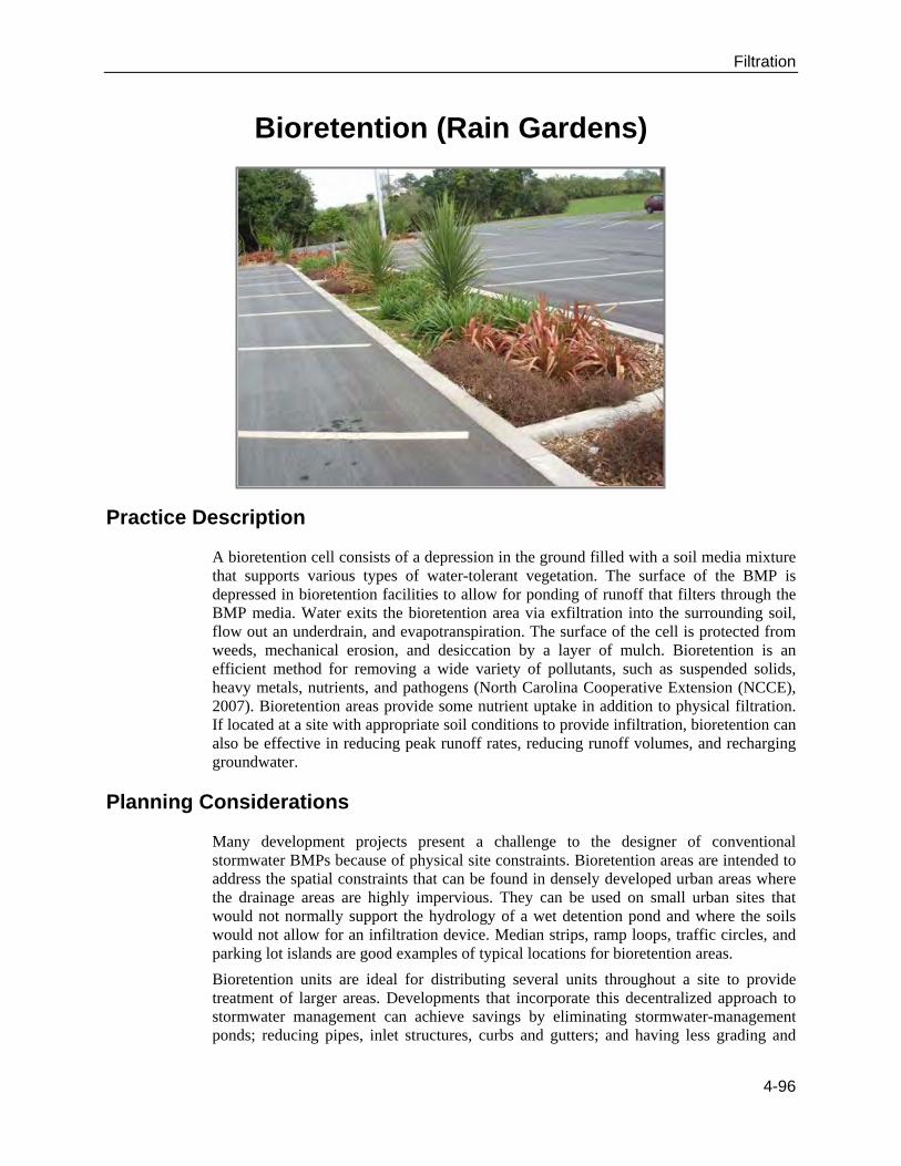
A bioretention cell consists of a depression in the ground filled with a soil media mixture that supports various types of water-tolerant vegetation. The surface of the BMP is depressed in bioretention facilities to allow for ponding of runoff that filters through the BMP media. Water exits the bioretention area via exfiltration into the surrounding soil, flow out an underdrain, and evapotranspiration. The surface of the cell is protected from weeds, mechanical erosion, and desiccation by a layer of mulch. Bioretention is an efficient method for removing a wide variety of pollutants, such as suspended solids, heavy metals, nutrients, and pathogens (North Carolina Cooperative Extension (NCCE), 2007). Bioretention areas provide some nutrient uptake in addition to physical filtration. If located at a site with appropriate soil conditions to provide infiltration, bioretention can also be effective in reducing peak runoff rates, reducing runoff volumes, and recharging groundwater.
Planning Considerations
Many development projects present a challenge to the designer of conventional stormwater BMPs because of physical site constraints. Bioretention areas are intended to address the spatial constraints that can be found in densely developed urban areas where the drainage areas are highly impervious. They can be used on small urban sites that would not normally support the hydrology of a wet detention pond and where the soils would not allow for an infiltration device. Median strips, ramp loops, traffic circles, and parking lot islands are good examples of typical locations for bioretention areas.
Bioretention units are ideal for distributing several units throughout a site to provide treatment of larger areas. Developments that incorporate this decentralized approach to stormwater management can achieve savings by eliminating stormwater-management ponds; reducing pipes, inlet structures, curbs and gutters; and having less grading and
4-96
Filtration
clearing. Depending on the type of development and site constraints, the costs for using decentralized bioretention stormwater-management methods can be reduced by 10 to 25 percent compared to stormwater and site development using other BMPs (Coffman, 1993).
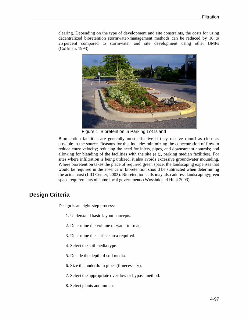
Figure 1 Bioretention in Parking Lot Island
Bioretention facilities are generally most effective if they receive runoff as close as possible to the source. Reasons for this include: minimizing the concentration of flow to reduce entry velocity; reducing the need for inlets, pipes, and downstream controls; and allowing for blending of the facilities with the site (e.g., parking median facilities). For sites where infiltration is being utilized, it also avoids excessive groundwater mounding. Where bioretention takes the place of required green space, the landscaping expenses that would be required in the absence of bioretention should be subtracted when determining the actual cost (LID Center, 2003). Bioretention cells may also address landscaping/green space requirements of some local governments (Wossink and Hunt 2003).
Design Criteria
Design is an eight-step process:
1. Understand basic layout concepts.
2. Determine the volume of water to treat.
3. Determine the surface area required.
4. Select the soil media type.
5. Decide the depth of soil media.
6. Size the underdrain pipes (if necessary).
7. Select the appropriate overflow or bypass method.
8. Select plants and mulch.
4-97
Filtration
Step 1: Understand Basic Layout Concepts
The layout of bioretention areas varies according to individual sites and to specific site constraints such as underlying soils, existing vegetation, drainage, location of utilities, sight distances for traffic, aesthetics, and ease of maintenance. Figure 2 illustrates a concept for a bioretention traffic island. These types of bioretention facilities typically take up no more space than what is required by typical zoning rules, and they provide stormwater treatment as well as site aesthetics. The following photographs are examples of existing bioretention cells that have been designed using these techniques. These cells blend into the landscape and appear to be typical flowerbeds or medians. Often, bioretention cells can be designed with flowering plants to enhance the landscape.
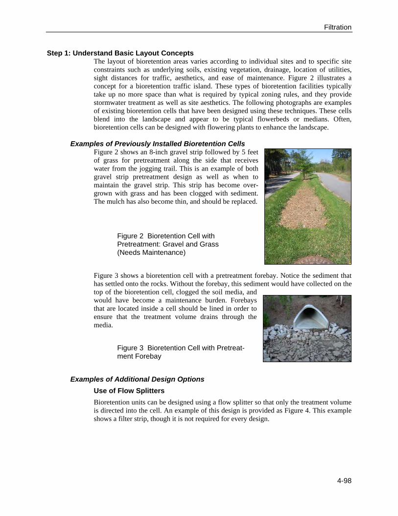
Examples of Previously Installed Bioretention Cells Figure 2 shows an 8-inch gravel strip followed by 5 feet of grass for pretreatment along the side that receives water from the jogging trail. This is an example of both gravel strip pretreatment design as well as when to maintain the gravel strip. This strip has become over-grown with grass and has been clogged with sediment. The mulch has also become thin, and should be replaced.
Figure 2 Bioretention Cell with Pretreatment: Gravel and Grass (Needs Maintenance)
Figure 3 shows a bioretention cell with a pretreatment forebay. Notice the sediment that has settled onto the rocks. Without the forebay, this sediment would have collected on the top of the bioretention cell, clogged the soil media, and would have become a maintenance burden. Forebays that are located inside a cell should be lined in order to ensure that the treatment volume drains through the media.
Figure 3 Bioretention Cell with Pretreat-ment Forebay
Examples of Additional Design Options
Use of Flow Splitters
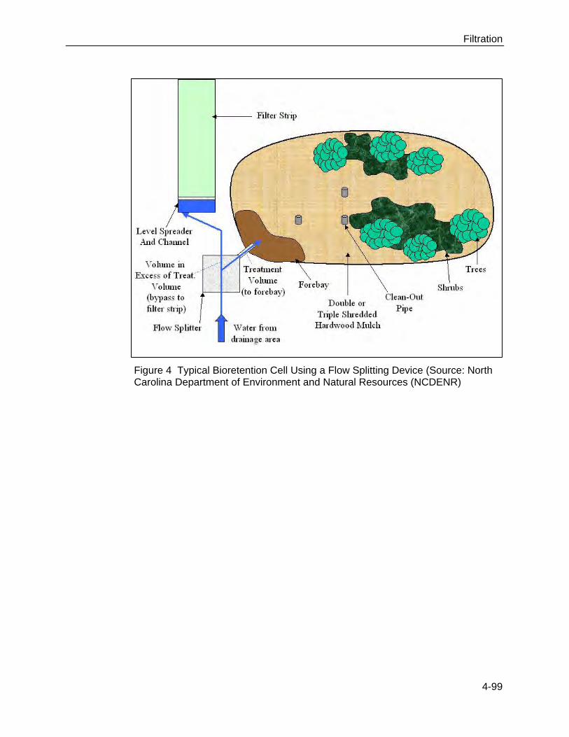
Bioretention units can be designed using a flow splitter so that only the treatment volume is directed into the cell. An example of this design is provided as Figure 4. This example shows a filter strip, though it is not required for every design.
4-98
Filtration
Figure 4 Typical Bioretention Cell Using a Flow Splitting Device (Source: North Carolina Department of Environment and Natural Resources (NCDENR)
4-99
Filtration
Use of Overflow Devices
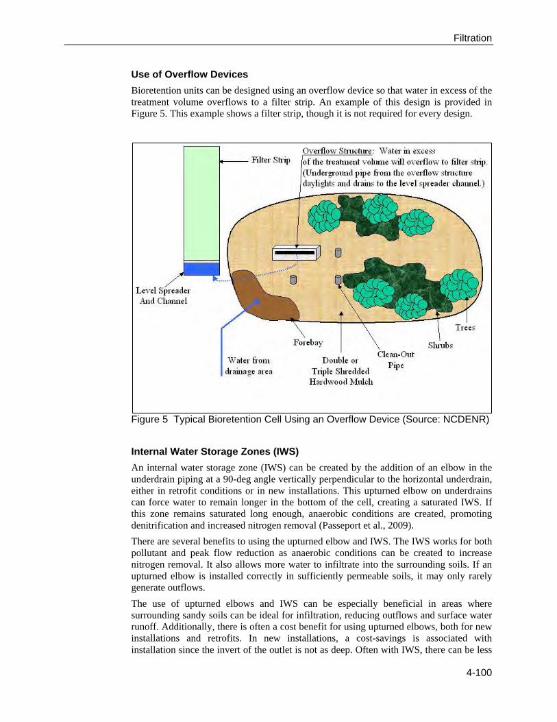
Bioretention units can be designed using an overflow device so that water in excess of the treatment volume overflows to a filter strip. An example of this design is provided in Figure 5. This example shows a filter strip, though it is not required for every design.
Figure 5 Typical Bioretention Cell Using an Overflow Device (Source: NCDENR)
Internal Water Storage Zones (IWS)
An internal water storage zone (IWS) can be created by the addition of an elbow in the underdrain piping at a 90-deg angle vertically perpendicular to the horizontal underdrain, either in retrofit conditions or in new installations. This upturned elbow on underdrains can force water to remain longer in the bottom of the cell, creating a saturated IWS. If this zone remains saturated long enough, anaerobic conditions are created, promoting denitrification and increased nitrogen removal (Passeport et al., 2009).
There are several benefits to using the upturned elbow and IWS. The IWS works for both pollutant and peak flow reduction as anaerobic conditions can be created to increase nitrogen removal. It also allows more water to infiltrate into the surrounding soils. If an upturned elbow is installed correctly in sufficiently permeable soils, it may only rarely generate outflows.
The use of upturned elbows and IWS can be especially beneficial in areas where surrounding sandy soils can be ideal for infiltration, reducing outflows and surface water runoff. Additionally, there is often a cost benefit for using upturned elbows, both for new installations and retrofits. In new installations, a cost-savings is associated with installation since the invert of the outlet is not as deep. Often with IWS, there can be less
4-100
Filtration
trenching and fewer materials associated with using it. In retrofits, upturned elbows can be cheaply added to existing bioretention cells where increased nitrogen and phosphorus removal rates are needed. Additionally, cells with IWS can be added as retrofits even in areas with restricted outlet depth.
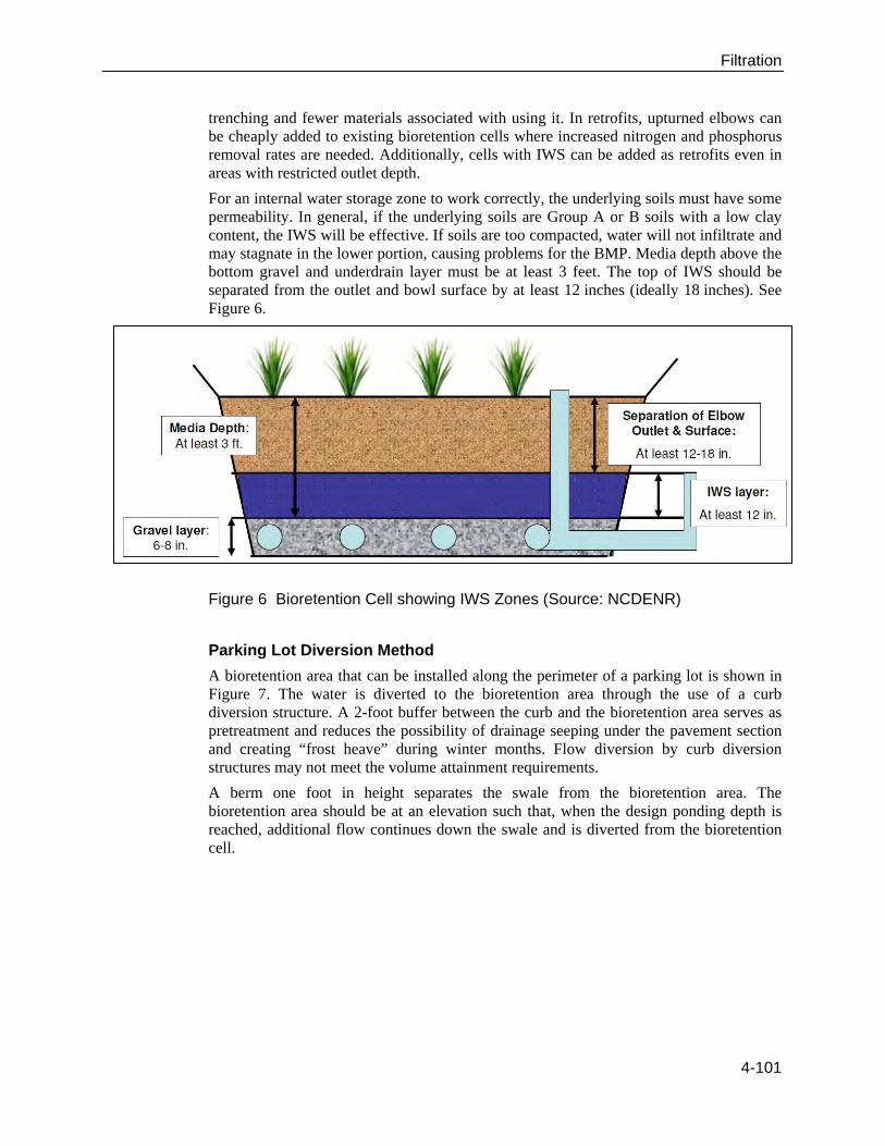
For an internal water storage zone to work correctly, the underlying soils must have some permeability. In general, if the underlying soils are Group A or B soils with a low clay content, the IWS will be effective. If soils are too compacted, water will not infiltrate and may stagnate in the lower portion, causing problems for the BMP. Media depth above the bottom gravel and underdrain layer must be at least 3 feet. The top of IWS should be separated from the outlet and bowl surface by at least 12 inches (ideally 18 inches). See Figure 6.
Figure 6 Bioretention Cell showing IWS Zones (Source: NCDENR)
Parking Lot Diversion Method
A bioretention area that can be installed along the perimeter of a parking lot is shown in Figure 7. The water is diverted to the bioretention area through the use of a curb diversion structure. A 2-foot buffer between the curb and the bioretention area serves as pretreatment and reduces the possibility of drainage seeping under the pavement section and creating “frost heave” during winter months. Flow diversion by curb diversion structures may not meet the volume attainment requirements.
A berm one foot in height separates the swale from the bioretention area. The bioretention area should be at an elevation such that, when the design ponding depth is reached, additional flow continues down the swale and is diverted from the bioretention cell.
4-101
Filtration
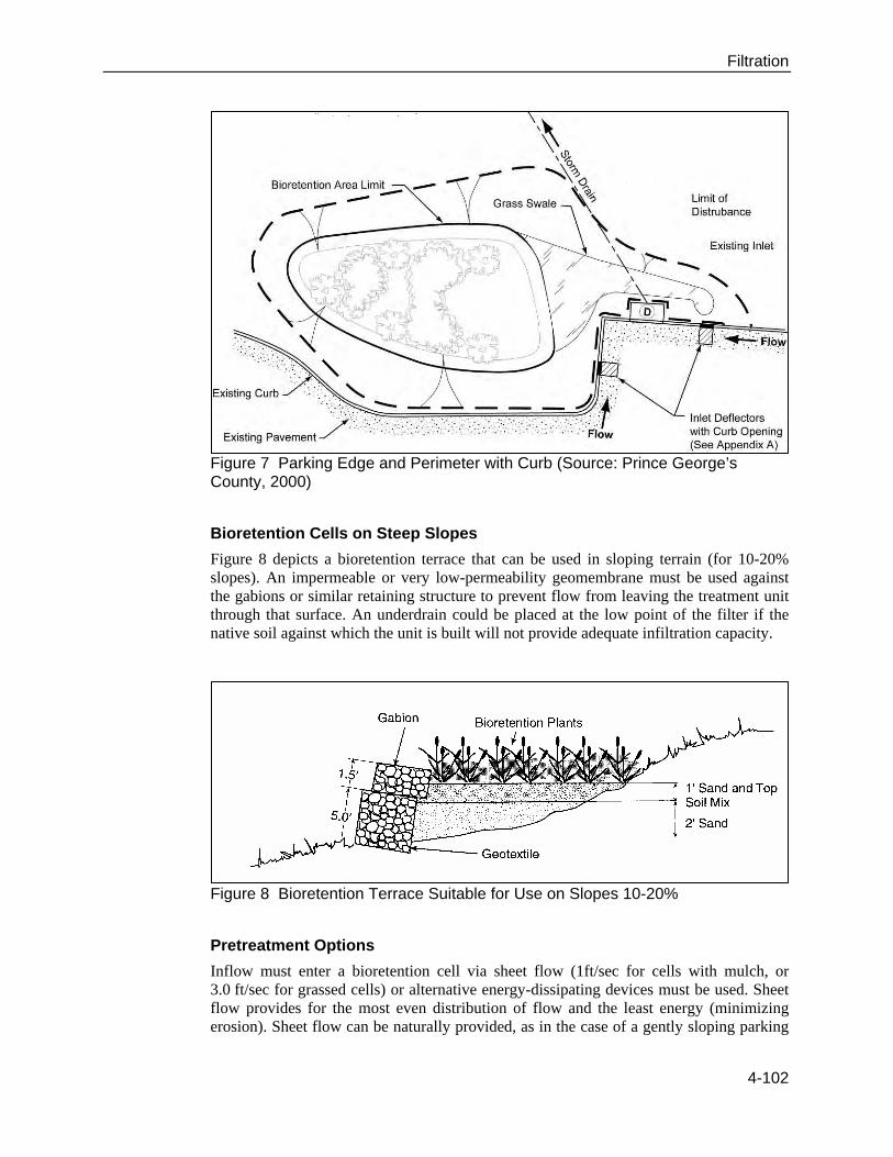
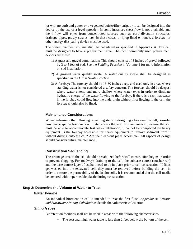
Figure 7 Parking Edge and Perimeter with Curb (Source: Prince George’s County, 2000)
Bioretention Cells on Steep Slopes
Figure 8 depicts a bioretention terrace that can be used in sloping terrain (for 10-20% slopes). An impermeable or very low-permeability geomembrane must be used against the gabions or similar retaining structure to prevent flow from leaving the treatment unit through that surface. An underdrain could be placed at the low point of the filter if the native soil against which the unit is built will not provide adequate infiltration capacity.
Figure 8 Bioretention Terrace Suitable for Use on Slopes 10-20%
Pretreatment Options
Inflow must enter a bioretention cell via sheet flow (1ft/sec for cells with mulch, or 3.0 ft/sec for grassed cells) or alternative energy-dissipating devices must be used. Sheet flow provides for the most even distribution of flow and the least energy (minimizing erosion). Sheet flow can be naturally provided, as in the case of a gently sloping parking
4-102
Filtration
lot with no curb and gutter or a vegetated buffer/filter strip, or it can be designed into the device by the use of a level spreader. In some instances sheet flow is not attainable and the inflow will enter from concentrated sources such as curb diversion structures, drainage pipes, grassy swales, etc. In these cases, a riprap-lined entrance, a forebay, or other energy-dissipating device must be used.
The water treatment volume shall be calculated as specified in Appendix A. The cell must be designed to have a pretreatment area. The most commonly used pretreatment devices are these:
1) A grass and gravel combination: This should consist of 8 inches of gravel followed by 3 to 5 feet of sod. See the Sodding Practice in Volume 1 for more information on sod installation.
2) A grassed water quality swale: A water quality swale shall be designed as specified in the Grass Swale Practice.
3) A forebay: The forebay should be 18-30 inches deep, and used only in areas where standing water is not considered a safety concern. The forebay should be deepest where water enters, and more shallow where water exits in order to dissipate hydraulic energy of the water flowing to the forebay. If there is a risk that water in the forebay could flow into the underdrain without first flowing to the cell, the forebay should also be lined.
Maintenance Considerations
When performing the following remaining steps of designing a bioretention cell, consider how landscape professionals will later access the site for maintenance. Because the soil must be able to accommodate fast water infiltration, it cannot be compacted by heavy equipment. Is the forebay accessible for heavy equipment to remove sediment from it without driving onto the cell? Are the clean-out pipes accessible? All aspects of design should consider future maintenance.
Construction Sequencing
The drainage area to the cell should be stabilized before cell construction begins in order to prevent clogging. For roadways draining to the cell, the subbase course (crusher run) and the base course layer of asphalt need to be in place prior to cell construction. If fines get washed into the excavated cell, they must be removed before building the cell, in order to restore the permeability of the in situ soils. It is recommended that the cell media be covered with impermeable plastic during construction.
Step 2: Determine the Volume of Water to Treat
Water Volume
An individual bioretention cell is intended to treat the first flush. Appendix A: Erosion and Stormwater Runoff Calculations details the volumetric calculation.
Siting Issues
Bioretention facilities shall not be used in areas with the following characteristics:
− The seasonal high water table is less than 2 feet below the bottom of the cell.
4-103

Filtration
− Slopes are 20 percent or greater, unless bioretention terraces are planned.
− Further construction is planned on either the immediately surrounding site or in outparcels that may drain to the bioretention site. (The upstream contributing drainage area must be completely and permanently stabilized, e.g., gravel base course driving surface (preferably paved), or a dense and vigorous vegetative cover. The heavy sediment load from a bare-earth construction site will cause premature failure of a bioretention BMP.)
− The cell is inaccessible for maintenance.
− The cell will not comply with local landscape ordinances.
Contributing Drainage Basin
Consider the effect of large storms on potential erosion within the cell as well as potential overflow and downhill erosion upon water leaving the cell. The contributing area to an individual bioretention cell will typically be 5 acres or less, because many large watersheds will not have an area that is large enough to serve the treatment volume while also being high enough above the water table.
Step 3: Determine the Surface Area and Depth Required
The cell can be designed to hold the first inch of rainfall from the entire drainage area. The required surface area of the bioretention cell is equal to the required treatment volume (as calculated using the Simple Method outlined in Appendix A) divided by the ponding depth. No dimension (width, length, or radius) can be less than 10 feet. This is to provide sufficient space for plants.
Step 4: Select the Soil Media Type
The soil mix should be uniform and free of stones, stumps, roots, or other similar material greater than 2 inches. It should be a homogenous soil mix of 85-88 percent by volume sand (USDA Soil Textural Classification), 8 to 12 percent fines (silt and clay), and 3 to 5 percent organic matter (such as peat moss). The higher (12 percent) fines content should be reserved for areas where total nitrogen is the target pollutant. In areas where phosphorus is the target pollutant, lower (8 percent) fines should be used. Additionally, the phosphorus (P) content of the soil mix should be low. The P-Index for bioretention soil media should always range between 10 and 30, regardless of the target pollutant (Hunt and Lord, 2006). The P-Index is an extremely important design element. Cells that are constructed of high P-Index soils can export phosphorus.
The media should be tested to determine an actual drainage rate after placement. The permeability should fall between 1 and 6 inches per hour, and 1-2 inches per hour is preferred. As a rule of thumb, using the above-specified media, the infiltration rates should be approximately 2 in./hr and 1 in./hr for 8% and 12% fines, respectively, depending on the target pollutant. An estimated drainage rate for percent fines between 8 and 12 can be approximated during design by linear interpolation. If total suspended solids (TSS) or pathogens are the target pollutant, the higher permeability can be used because these two pollutants are removed on the surface of the bioretention cell rather than within the cell.
4-104
Filtration
Step 5: Determine the Soil Media Depth
Different pollutants are removed in various zones of the bioretention cell using several mechanisms. The TSS are removed both in pretreatment and on the surface of the cell itself. For that reason, TSS removal is not a major factor in depth of the cell design. Depth is, however, an issue for other pollutants. Metals are removed in the top layer of mulch and the soil, as they are often bound to sediment. Additionally, two thirds of phosphorus entering the cell is attached to soil particles. As a result, this portion is removed on the surface. The remaining third is soluble and is removed 12 inches or more below the surface. Bacterial, viral, and protozoan pathogens can be killed on the surface and removed throughout the cell by several mechanisms: sun-exposure, drying, sedimentation, and filtration (Hathaway and Hunt, 2008). Temperature is reduced at approximately 48 inches below the surface. Nitrogen is removed 30 inches below the surface. Initial research at North Carolina State University shows that using an upturned underdrain pipe may increase nitrogen removal. The upturned piped creates an anaerobic zone that may facilitate nitrogen removal. (See the Internal Water Storage Zones section of this practice for more information.) Consider the types of pollutants to be removed, and select an appropriate media depth.
The ponding depth above the media and mulch shall be 12 inches or less (9 inches or less is preferred). This is based on both the typical inundation tolerance of the vegetation used in bioretention facilities as well as the ability of the ponded water to drain into the soil within the required time.
The depth of the media in a bioretention cell should be between 2 and 4 feet. This range reflects the fact that most of the pollutant removal occurs within the first 2 feet of soil, and excavations deeper than 4 feet become more expensive. The depth should accommodate the vegetation (shrubs or trees). If the minimum depth of 2 feet is used, only shallow-rooted plants can be planted. Grassed bioretention cells with no IWS can be as shallow as 2 feet. However, if nitrogen is the target pollutant, the cell should have at least 30 inches of media because, as previously discussed, nitrogen is removed 30 inches below the surface. Bioretention facilities where shrubs or trees are planted can be as shallow as 3 feet. If large trees are to be planted in deep fill media, care should be taken to ensure that they would be stable and not fall over. As stated above, if IWS is used, cells must have a minimum depth of 3 feet.
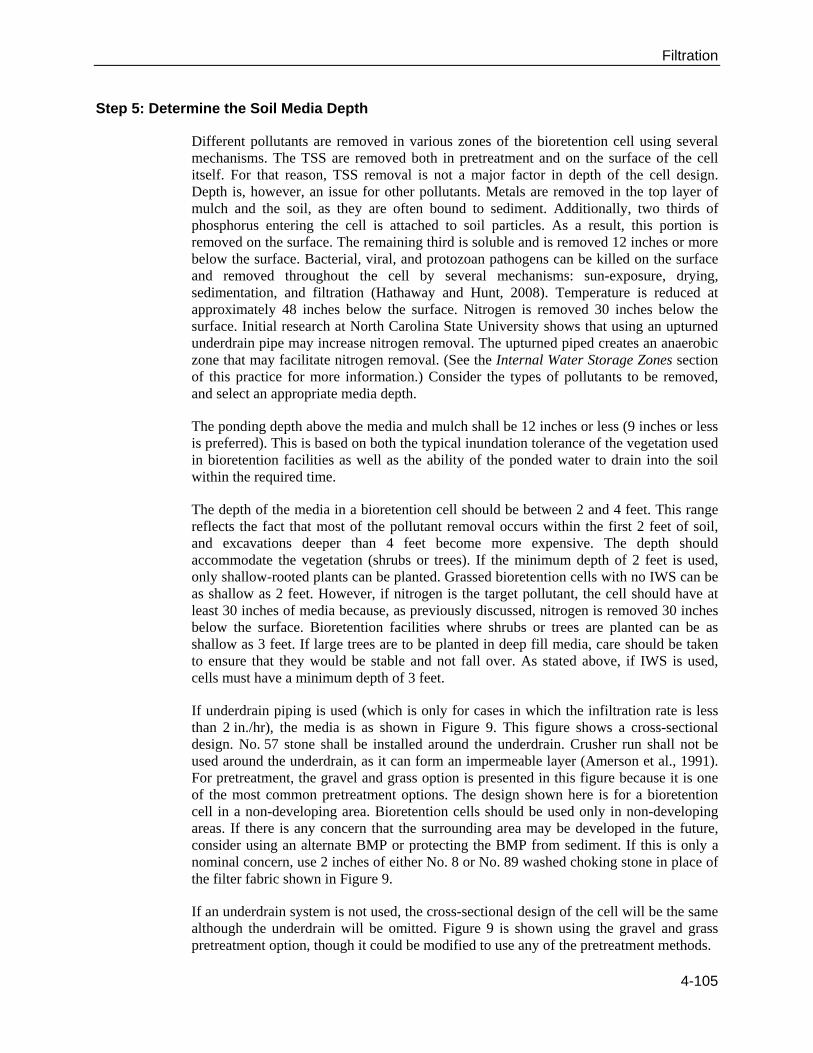
If underdrain piping is used (which is only for cases in which the infiltration rate is less than 2 in./hr), the media is as shown in Figure 9. This figure shows a cross-sectional design. No. 57 stone shall be installed around the underdrain. Crusher run shall not be used around the underdrain, as it can form an impermeable layer (Amerson et al., 1991). For pretreatment, the gravel and grass option is presented in this figure because it is one of the most common pretreatment options. The design shown here is for a bioretention cell in a non-developing area. Bioretention cells should be used only in non-developing areas. If there is any concern that the surrounding area may be developed in the future, consider using an alternate BMP or protecting the BMP from sediment. If this is only a nominal concern, use 2 inches of either No. 8 or No. 89 washed choking stone in place of the filter fabric shown in Figure 9.
If an underdrain system is not used, the cross-sectional design of the cell will be the same although the underdrain will be omitted. Figure 9 is shown using the gravel and grass pretreatment option, though it could be modified to use any of the pretreatment methods.
4-105
Filtration
This figure also shows an overflow structure. Typically, an overflow structure is adapted from an existing drainage culvert inlet.
In Figure 9, the vertical sides of the bioretention cell do not have to be at a specified angle. However, the surface area of the bottom of the cell should be maximized.
Figure 9: Bioretention Conceptual Layout: Cross-Section (Source: NCDENR)
Sediment Accumulation
There should be very little, if any, sediment accumulation in a bioretention cell, since the upstream drainage basin must be stabilized prior to bringing the bioretention cell into service, and since pretreatment is required prior to the BMP.
4-106
Filtration
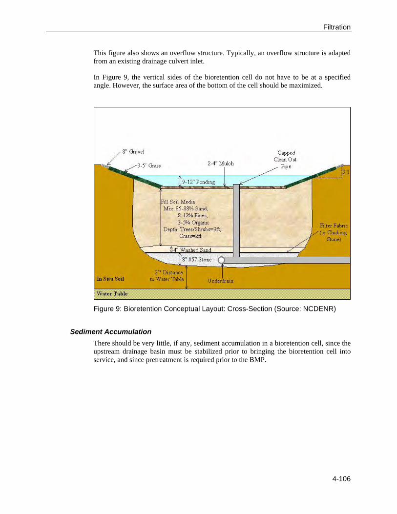
Drainage Considerations
Water shall pond above the cell for a maximum of 12 hours. Water must then drain to a level 24 inches below the surface of the cell within 48 hours (maximum) to allow the appropriate contact time for pollutant removal. This requirement is demonstrated in Figure 10. The time to drain the ponded volume is simply the depth of the ponding in inches, divided by the limiting drainage rate. If the cell has an underdrain, the length of time that it takes to drain the ponding volume of a bioretention cell is controlled by the infiltration rate of the media. If the cell does not have an underdrain and is an infiltration type system, it will be controlled by the lesser of the infiltration rate of the media or the infiltration rate of the native soil.
Figure 10: Bioretention Drain Time (Source: NCDENR)
Step 6: Size the Underdrains (if required)
The need for an underdrain is driven by the permeability of the in situ soil. If the in situ soil has a high permeability, the system can be designed as an infiltration type bioretention facility with no underdrains. If in situ soil permeability is less than 2 inches/hour, the bioretention facility will likely have an underdrain system. If the in situ soil drains more slowly than the planting media, the designer should include an explanation of how water will drain from the media. The underdrain system will connect to another BMP or to the conveyance system. Due to the risk of underdrain clogging, designers are encouraged to install more than one underdrain of smaller diameter in order to facilitate drainage. The minimum diameter of pipe for underdrain systems is four inches. As previously discussed, an upturned elbow may be used.
Clean-out pipes must be provided (minimum one per every 1,000 square feet of surface area). Clean-out pipes must be capped.
Step 7: Select the Appropriate Overflow Structure
The overflow structure should be sized to accommodate storm volumes in excess of the first flush. The first available outlet on the outlet structure should therefore be placed at
4-107
Filtration
the height of the first flush, which is the ponded level of the bioretention cell. Use the weir equation to consider the height of the water above the weir during overflow from large storm events. Typically, water can rise about 2 inches above the ponded water level. But, this height can be higher, about 4″-6″ above the ponded water level, if required by design restraints. A particular design storm is not specified for overflow structure design. Professional judgment should be used when considering potential flooding risks outside the bioretention cell.
Step 8: Select Plants and Mulch
Plants are an integral element of the bioretention system’s pollutant removal and water filtration process. Plant roots aid in the physical and chemical bonding of soil particles necessary to form stable aggregates, improve soil structure, and increase infiltration capacity. Vegetated soils are more capable of more effective degradation, removal, and mineralization of total petroleum hydrocarbons, polycyclic aromatic hydrocarbons, pesticides, chlorinated solvents, and surfactants than are nonvegetated soils (USEPA, 2000).
The primary design considerations for plant selection include the following:
1. Soil moisture conditions: Soil moisture conditions will vary widely within the bioretention facility from saturated (bottom of cell) to relatively dry (rim of cell), as well as over time. Therefore, the predominant plant material utilized should be facultative species adapted to stresses associated with both wet and dry conditions (MDER, 2002). In some cases, the in situ soil can be ripped and amended so that vegetation can grow.
2. Pollutant loadings: Since bioretention is often specified for use in impaired and/or nutrient-sensitive watersheds, strategic use of particular plants for phytoremediation purposes is crucial. Plants should tolerate typical pollutants and loadings from the surrounding land uses.
3. Above- and below-ground infrastructure in and near the bioretention facility: Plant selection should consider the surrounding conditions, including light pollution tolerance, wind, and above- and below-ground utilities. Slotted or perforated pipes should be more than 5 feet away from tree locations. Plants with taproots should not be used.
4. Adjacent plant communities and potential invasive species control.
5. Site distances and setbacks for roadway applications.
6. Visual buffering: Plants can be used to buffer structures from roads, enhance privacy among residences, and provide an aesthetic amenity for the site.
7. Aesthetics: Visually pleasing plant designs add to the property and encourage community and homeowner acceptance. Public education and participation in the plant selection and design should be encouraged to promote greater involvement in long-term care.
8. Grass may be used; however, grassed cells must be sodded (not seeded), and the sod must not be grown in soil that has an impermeable layer, such as clay.
4-108
Filtration
Planting design will vary with the surrounding landscape context and design objectives. For example, the use of plants in bioretention areas could replicate a variety of native terrestrial ecosystems, including forests, ornamental gardens, meadows, hedgerows, and wetlands, as well as wildlife habitats.
A minimum of one tree, three shrubs, and three herbaceous species should be incorporated in the bioretention planting plan unless it is a grassed cell. A diverse plant community is necessary to avoid susceptibility to insects and disease. A recommended minimum planting density is 400 stems/acre. Bacteria die-off occurs at the surface where stormwater is exposed to sunlight and the soil can dry out. Therefore, it is best for bioretention cells to not be too densely vegetated in order to allow greater exposure to sunlight and consequent die-off of bacteria (NCCE 2007).
The plants selected should be able to tolerate typical stormwater pollutant loads, variable (often very dry) soil moisture, temporary submergence, and extended wet conditions. Consult a design profession for the selection of plants.
To increase survival rates and ensure quality of plant materials, the following general guidelines for plantings within bioretention facilities are recommended:
All plant material should conform to the standards of the current edition of
American Standards for Nursery Stock as approved by the American Standards Institute, Inc. All plant grades shall be those established by the current edition of American Standards for Nursery Stock [http://www.anla.org/applications/Documents/Docs/ANLAStandard2004.pdf].
All plant materials should have normal, well-developed branches and vigorous root systems, and be free from physical defects, plant diseases, and insect pests.
All plant materials should be tagged for identification when delivered.
Optimum planting time is fall. Winter planting is acceptable. Spring is acceptable but will require more summer watering than fall planting. Summer planting is the least desirable, as it drastically increases plant mortality and requires regular watering immediately following installation.
− Plant size should be no less than 2.5″ diameter at breast height for trees; 3-gallon for shrubs; and 1-quart for herbaceous plants.
Woody vegetation should not be planted at inflow locations.
For best survival, trees should be planted with the top of the root ball partially out of the media. They should be planted to have from 1/3 to 1/2 of the root ball within the media. This would leave from 2/3 to 1/2 of the root ball above the media.
Local jurisdictions often have specific guidelines for the types and location of trees and other landscape plants planted along public streets or rights-of-way. Additionally, local landscape ordinances must be followed. Contact local authorities to determine if there are guidelines or restrictions to consider when making plant selections for your project.
4-109
Filtration
The mulch layer plays an important function in the performance of the bioretention system by reducing weed establishment; regulating soil temperatures and moisture; reducing soil compaction from rainfall; preventing erosion; and promoting an environment suitable for soil microorganisms at the mulch/soil interface (important for filtering nutrients and other pollutants). Mulches prevent soil and possible fungi from splashing on the foliage, reducing the likelihood of soil-borne diseases (Evans, 2000). Mulch serves as a pretreatment layer by trapping the finer sediments that remain suspended after the primary pretreatment. Additionally, most attenuation of heavy metals in bioretention facilities occurs in the first 1-2 inches of the mulch layer (Hinman, 2005). Other considerations related to mulch are these:
Mulch should be free of weed seeds, soil, roots, and other material that is not bole or branch wood or bark.
Use commercially available double- or triple-shredded hardwood mulch. This mulch has been found to be less likely to wash away than other forms of mulch (such as pine).
Mulch depth depends on the type of material used and the drainage and moisture-holding capacity of the soil. A 2-4 inch layer (after settling) is adequate for most applications. Excessive application of mulch can result in a situation where the plants are growing in the mulch and not the soil. Over-mulched plants are easily damaged during periods of drought stress. Mulching in an area that is poorly drained can aggravate the condition (Evans, 2000).
Mulch can be applied any time of year; however, the best time to mulch is late spring after the soil has warmed.
Mulch should be at least 6 months old (12 months is ideal). It should be placed uniformly, about 3 inches deep. Mulch should be renewed as needed to maintain a 2-4″ depth; on previously
mulched areas, apply a one-inch layer of new material. It should be added 1-2 times per year and completely removed/replaced once every two years.
Siting Considerations Some considerations for selecting a stormwater-management practice are the drainage area the practice will need to treat, the slopes both at the location of the practice and the drainage area, soil and subsurface conditions, and the depth of the seasonably high groundwater table. Bioretention can be applied on many sites, with its primary restriction being the need to apply the practice on small sites.
Drainage Area
Bioretention areas should, in general, be used on small sites (i.e., 5 acres or less). When used to treat larger areas, they tend to clog. In addition, it is difficult to convey flow from a large area to a bioretention area.
Slope
Bioretention areas are best applied to relatively shallow slopes (usually about 5 percent). However, sufficient slope is needed at the site to ensure that water that enters the bioretention area can be connected with the storm drain system. These stormwater-management practices are most often applied to parking lots or residential landscaped areas, which generally have shallow slopes.
4-110
Filtration
Soils/Topography
Bioretention areas can be applied in almost any soils or topography, since runoff percolates through a man-made soil bed and is returned to the stormwater system.
Groundwater
Bioretention should be separated somewhat from the groundwater to ensure that the groundwater table never intersects with the bed of the bioretention facility. This design consideration prevents possible groundwater contamination.
Design Variations
One design alternative to the traditional bioretention practice is the use of a “partial exfiltration” system, used to promote groundwater recharge. Other design modifications may make this practice more effective in arid or cold climates.
Partial Exfiltration
In one design variation of the bioretention system, the underdrain is installed on only part of the bottom of the system. This design alternative allows for some infiltration, with the underdrain acting as more of an overflow. This system can be applied only when the soils and other characteristics are appropriate for infiltration (see Infiltration Trench and Infiltration Basin).
Common Problems
Bioretention areas have a few limitations. Bioretention areas cannot be used to treat a large drainage area, limiting their usefulness for some sites. In addition, although the practice does not consume a large amount of space, incorporating bioretention into a parking lot design may reduce the number of parking spaces available if islands were not previously included in the design.
Maintenance
Common maintenance activities include re-mulching, treating diseased trees and shrubs, and mowing turf areas.
Newly planted vegetation should be watered regularly until properly established.
Erosion issues should be addressed immediately.
4-111
Filtration
Catch Basin Inserts
Practice Description
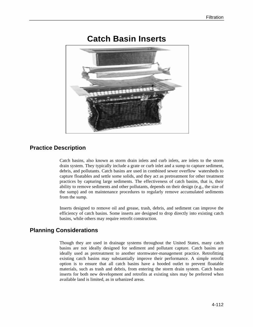
Catch basins, also known as storm drain inlets and curb inlets, are inlets to the storm drain system. They typically include a grate or curb inlet and a sump to capture sediment, debris, and pollutants. Catch basins are used in combined sewer overflow watersheds to capture floatables and settle some solids, and they act as pretreatment for other treatment practices by capturing large sediments. The effectiveness of catch basins, that is, their ability to remove sediments and other pollutants, depends on their design (e.g., the size of the sump) and on maintenance procedures to regularly remove accumulated sediments from the sump.
Inserts designed to remove oil and grease, trash, debris, and sediment can improve the efficiency of catch basins. Some inserts are designed to drop directly into existing catch basins, while others may require retrofit construction.
Planning Considerations
Though they are used in drainage systems throughout the United States, many catch basins are not ideally designed for sediment and pollutant capture. Catch basins are ideally used as pretreatment to another stormwater-management practice. Retrofitting existing catch basins may substantially improve their performance. A simple retrofit option is to ensure that all catch basins have a hooded outlet to prevent floatable materials, such as trash and debris, from entering the storm drain system. Catch basin inserts for both new development and retrofits at existing sites may be preferred when available land is limited, as in urbanized areas.
4-112

Filtration
Design Criteria
The performance of catch basins is related to the volume in the sump (i.e., the storage in the catch basin below the outlet). Lager et al. (1997) described an “optimal” catch basin sizing criterion, which relates all catch basin dimensions to the diameter of the outlet pipe (D):
The diameter of the catch basin should be equal to 4D. The sump depth should be at least 4D. This depth should be increased if cleaning
is infrequent or if the area draining to the catch basin has high sediment loads. The top of the outlet pipe should be 1.5D from the bottom of the inlet to the catch
basin.
Catch basins can also be sized to accommodate the volume of sediment that enters the system. Pitt et al., (1997) proposed a sizing criterion based on the concentration of sediment in stormwater runoff. The catch basin is sized, with a factor of safety, to accommodate the annual sediment load in the catch basin sump. This method is preferable where high sediment loads are anticipated, and where the optimal design described above is suspected to provide little treatment.
The basic design should also incorporate a hooded outlet to prevent floatable materials and trash from entering the storm drain system. Adding a screen to the top of the catch basin would not likely improve the performance of catch basins for pollutant removal, but it would help capture trash entering the catch basin (Pitt et al., 1997).
Several varieties of catch basin inserts exist for filtering runoff. One insert option consists of a series of trays, with the top tray serving as an initial sediment trap, and the underlying trays composed of media filters. Another option uses filter fabric to remove pollutants from stormwater runoff. Yet another option is a plastic box that fits directly into the catch basin. The box construction is the filtering medium. Hydrocarbons are removed as the stormwater passes through the box, while trash, rubbish, and sediment remain in the box itself as stormwater exits. These devices have a very small volume, compared to the volume of the catch basin sump, and would typically require very frequent sediment removal. Bench test studies found that a variety of options showed little removal of total suspended solids, partially due to scouring from relatively small (6-month) storm events (ICBIC, 1995).
One design adaptation of the standard catch basin is to incorporate infiltration through the catch basin bottom. Two challenges are associated with this design. The first is potential groundwater impacts, and the second is potential clogging, preventing infiltration. Infiltrating catch basins should not be used in commercial or industrial areas, because of possible groundwater contamination. While it is difficult to prevent clogging at the bottom of the catch basin, it might be possible to incorporate some pretreatment into the design.
Drainage Area The total maximum drainage area should be 5,000 square feet (+5%) per unit for new development projects and 7,000 feet per unit for redevelopment projects.
4-113
Filtration
Accessibility
The insert should be located so that is it readily accessible for maintenance requirements and so that it will not be blocked by parked vehicles.
Common Problems
Even ideally designed catch basins cannot remove pollutants as well as structural stormwater-management practices, such as wet ponds, sand filters, and stormwater wetlands.
Unless frequently maintained, catch basins can become a source of pollutants through resuspension.
Catch basins cannot effectively remove soluble pollutants or fine particles.
Maintenance
Typical maintenance of catch basins includes trash removal (if a screen or other debris-capturing device is used) and removal of sediment using a vacuum truck. Operators need to be properly trained in catch basin maintenance. Maintenance should include keeping a log of the amount of sediment collected and the date of removal. Some cities have incorporated the use of geographic information systems to track sediment collection and to optimize future catch basin cleaning efforts.
One study (Pitt, 1985) concluded that catch basins can capture sediments up to approximately 60 percent of the sump volume. When sediment fills greater than 60 percent of their volume, catch basins reach steady state. Storm flows can then re-suspend sediments trapped in the catch basin, and will bypass treatment. Frequent clean-out can retain the volume in the catch basin sump available for treatment of stormwater flows.
At a minimum, catch basins should be cleaned once or twice per year (Aronson et al., 1993). In some regions, it may be difficult to find environmentally acceptable disposal methods for collected sediments. The sediments may not always be land-filled, land-applied, or introduced into the sanitary sewer system due to hazardous waste, pretreatment, or groundwater regulations. This is particularly true when catch basins drain runoff from hot-spot areas.
4-114
Filtration
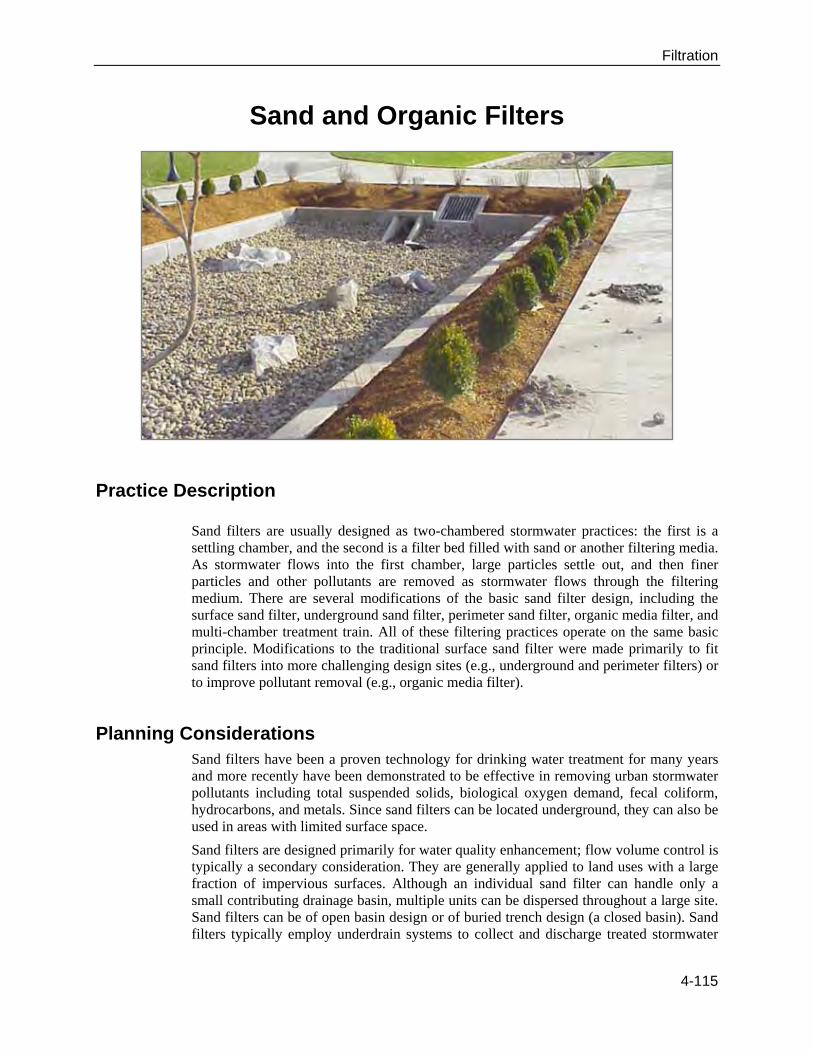
Sand and Organic Filters
Practice Description
Sand filters are usually designed as two-chambered stormwater practices: the first is a settling chamber, and the second is a filter bed filled with sand or another filtering media. As stormwater flows into the first chamber, large particles settle out, and then finer particles and other pollutants are removed as stormwater flows through the filtering medium. There are several modifications of the basic sand filter design, including the surface sand filter, underground sand filter, perimeter sand filter, organic media filter, and multi-chamber treatment train. All of these filtering practices operate on the same basic principle. Modifications to the traditional surface sand filter were made primarily to fit sand filters into more challenging design sites (e.g., underground and perimeter filters) or to improve pollutant removal (e.g., organic media filter).
Planning Considerations Sand filters have been a proven technology for drinking water treatment for many years and more recently have been demonstrated to be effective in removing urban stormwater pollutants including total suspended solids, biological oxygen demand, fecal coliform, hydrocarbons, and metals. Since sand filters can be located underground, they can also be used in areas with limited surface space.
Sand filters are designed primarily for water quality enhancement; flow volume control is typically a secondary consideration. They are generally applied to land uses with a large fraction of impervious surfaces. Although an individual sand filter can handle only a small contributing drainage basin, multiple units can be dispersed throughout a large site. Sand filters can be of open basin design or of buried trench design (a closed basin). Sand filters typically employ underdrain systems to collect and discharge treated stormwater
4-115

Filtration
but can also be designed as infiltration type systems when located in soils with sufficient permeability or infiltration rates.
Sand filters are a good option to achieve water quality goals in retrofit studies where space is limited, because they consume very little surface space and have few site restrictions. It is important to note, however, that sand filters cannot treat a very large drainage area. Using small-site BMPs in a retrofit may be the only option for a retrofit study in a highly urbanized area, but it is expensive to treat the drainage area of an entire watershed using many small-site practices, as opposed to one larger facility such as a pond.
Design Criteria Converting Erosion- and Sediment-Control Devices
A basin used for construction erosion and sediment control can be converted into an open basin-type sand filter if all sediment is removed from the basin prior to construction of the sand filter and proper sand filter design is followed. Buried trench-type sand filters are typically newly constructed after site construction and not placed in modified site construction sediment- and erosion-control basins. Sand filters are not to be brought on-line until site construction activities are completed and groundcover is fully stabilized.
Drainage Area
The maximum contributing drainage area to an individual sand filter shall be less than 5 acres; however, 1 acre or less is recommended. Multiple sand filters can be used throughout a development to provide treatment for larger sites.
Slope
Sand filters can be used on sites with slopes up to about 6 percent. It is challenging to use most sand filters in very flat terrain because they require a significant amount of elevation drop, or head (about 5 to 8 feet), to allow flow through the system. One exception is the perimeter sand filter, which can be applied with as little as 2 feet of head.
Soils/Topography
When sand filters are designed as a stand-alone practice, they can be used on almost any soil because they can be designed so that stormwater never infiltrates into the soil or interacts with the groundwater. Alternatively, sand filters can be designed as pretreatment for an infiltration practice, where soils do play a role.
Groundwater
Designers should provide at least 2 feet of separation between the bottom of the filter and the seasonally high groundwater table. This design feature prevents both structural damage to the filter and possibly, though unlikely, groundwater contamination.
Pretreatment
Erosive velocities and high sediment loads are a concern with sand filters. Sediment can quickly blind a sand filter and cause premature failure of the BMP. Two devices that reduce the impact of these factors on the sand filter are flow splitter devices and forebays.
Flow beyond the design flow can overload the hydraulic capacity of a sand filter (usually resulting in an overflow), cause erosion in open basin sand filters, and deliver more
4-116
Filtration
sediment to the sand filter than is necessary. Because of these issues, sand filters are required to be designed “off-line,” meaning only the design volume of the stormwater flow is sent from the conveyance system into the treatment unit, and the excess is diverted.
A forebay or sedimentation chamber is required on all sand filters, to protect the sand filter from clogging due to sediment and to reduce the energy of the influent flow. The forebay can be in the form of an open basin (typical with an open basin sand filter design), or a subsurface concrete chamber (typical with a buried trench design). The forebay must contain ponded water (not be drained down with the sand filter). If a subsurface concrete chamber is provided, appropriate means of removing accumulated sediment must be demonstrated. Since individual sand filters treat relatively small volumes of stormwater and the design of the forebay is a percent of the total design volume, the forebay can also be very small. The minimum width (measurement parallel to flow direction) of the sedimentation chamber or forebay shall be 1.5 feet.
Following the sedimentation chamber or forebay, stormwater flow may be distributed over the surface of the sand filter in a variety of ways. In an open design, it could flow onto the sand filter as sheet flow via a level spreader. Depending on the geometry of the sand filter, however, that may not provide enough flow distribution to prevent overloading and clogging of the leading edge of the sand filter. One common method of distributing flow onto sand filters, both the open basin and buried trench types, is through the use of a pipe distribution or weir system.
Length, Width and Geometry
The area required for a sand filter device is calculated similar to many other BMP types. Since a sand filter must be completely drained within 40 hours, the ponding depth is a function of the media’s infiltration rate. Once the ponding depth is known, the surface area can be calculated based on the design volume.
A sand filter consists of two parts, the sedimentation basin (which serves as a sort of forebay) and the sand filter itself. These two parts are collectively referred to as the “sand filter.” An open basin type sand filter can be rectangular, square, circular, or irregular. Buried trench systems (closed basin systems) are often very rectangular, approaching linear. The important factor is that incoming stormwater is distributed relatively evenly over the surface of the sand filter. The following series of steps are used to determine the appropriate sand filter size.
Step 1: Compute the water quality volume (WQV) using Schueler’s Simple Method, as described in Chapter 3 and summarized below, and the adjusted water quality volume (WQVAdj) as defined below (CWP, 1996).
in
ftx
inchRainRx
Acre
ftx
acresAx
unitlessRftWQV DDv
1211
560,43
1
)(
1
)()(
23
WQVftWQVAdj )75.0()( 3
WQV: Water Quality Volume (ft3). This is used to size the surface areas of
the sedimentation chamber and the sand filter.
4-117
Filtration
WQVAdj: Adjusted Water Quality Volume (ft3). This is used as the volume
that must be contained between the sedimentation chamber and the sand filter (above the sand).
AD: Drainage area to the sand filter (acres) Rv: Volumetric runoff coefficient (unitless) = 0.05 + 0.009(%Imp)
o %Imp: Percent of impervious of land draining to the sand filter
Step 2: Determine the maximum and average head on the sand filter, and determine the surface areas of the sand filter and the sedimentation chamber. Maximum Head on the Sand Filter
hMaxFilter(ft): Maximum head on the sand filter (ft). This head is typically measured from the top of the overflow weir, which separates the sediment chamber from the sand chamber, to the top of the sand and should be no more than 6 feet. Choose the maximum head so that the following equation is true:
)()(
)()(
22
3
ftAftA
ftWQVfth
fS
AdjMaxFilter
As: Surface area of the sedimentation basin (ft2) Af: Surface area of the sand filter bed (ft2)
2
)()(
fthfth MaxFilter
A
hA = Average head (ft). The average head on the sand filter is approximately equal to the average head on the sedimentation basin.
Sedimentation Basin Surface Area: The minimum surface area for the sedimentation basin is determined by the Camp Hazen Equation:
22
22
2
22
3
2
3
2
*)(*)(*240)(
)()(12
)(1
1
)(
)(
)(560,43
1
)(
1
)(066.0)(
)(066.0)(
)9.01ln(
sec0004.0
sec3600
1
24
)(
)(
1ln
sec
sec)(
ftRacresAunitlessRftA
ftin
ftx
inRx
Acre
ftx
AcresAx
unitlessRftA
ftWQVftA
xft
hrx
hr
ftWQV
ftA
Exft
w
ftQ
ftA
DDvS
DDvS
S
S
o
s
4-118
Filtration
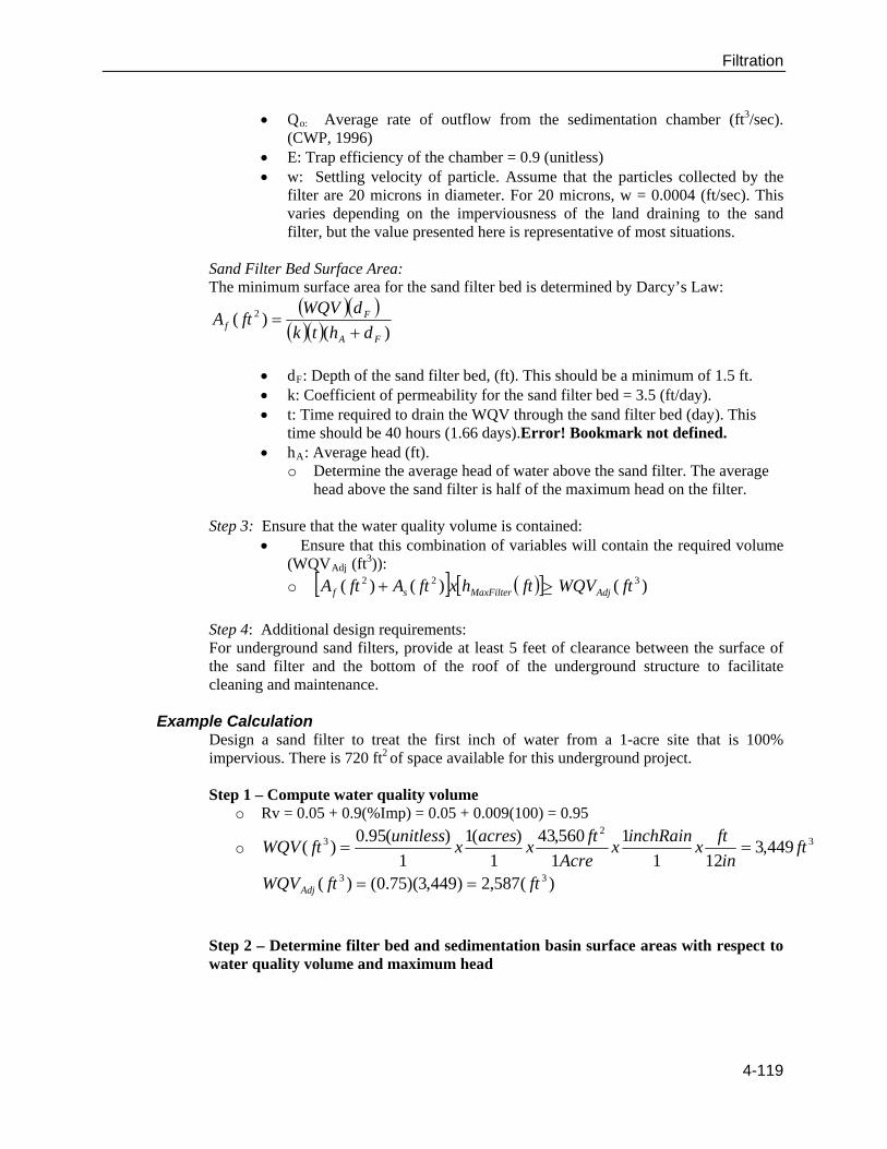
Qo: Average rate of outflow from the sedimentation chamber (ft3/sec).
(CWP, 1996) E: Trap efficiency of the chamber = 0.9 (unitless) w: Settling velocity of particle. Assume that the particles collected by the
filter are 20 microns in diameter. For 20 microns, w = 0.0004 (ft/sec). This varies depending on the imperviousness of the land draining to the sand filter, but the value presented here is representative of most situations.
Sand Filter Bed Surface Area: The minimum surface area for the sand filter bed is determined by Darcy’s Law:
)(
)( 2
FA
Ff dhtk
dWQVftA
dF: Depth of the sand filter bed, (ft). This should be a minimum of 1.5 ft. k: Coefficient of permeability for the sand filter bed = 3.5 (ft/day). t: Time required to drain the WQV through the sand filter bed (day). This
time should be 40 hours (1.66 days).Error! Bookmark not defined. hA: Average head (ft).
o Determine the average head of water above the sand filter. The average head above the sand filter is half of the maximum head on the filter.
Step 3: Ensure that the water quality volume is contained:
Ensure that this combination of variables will contain the required volume (WQVAdj (ft
3)):
o )()()( 322 ftWQVfthxftAftA AdjMaxFiltersf
Step 4: Additional design requirements: For underground sand filters, provide at least 5 feet of clearance between the surface of the sand filter and the bottom of the roof of the underground structure to facilitate cleaning and maintenance.
Example Calculation Design a sand filter to treat the first inch of water from a 1-acre site that is 100% impervious. There is 720 ft2 of space available for this underground project. Step 1 – Compute water quality volume
o Rv = 0.05 + 0.9(%Imp) = 0.05 + 0.009(100) = 0.95
o 32
3 449,3121
1
1
560,43
1
)(1
1
)(95.0)( ft
in
ftx
inchRainx
Acre
ftx
acresx
unitlessftWQV
)(587,2)449,3)(75.0()( 33 ftftWQVAdj
Step 2 – Determine filter bed and sedimentation basin surface areas with respect to water quality volume and maximum head
4-119
Filtration
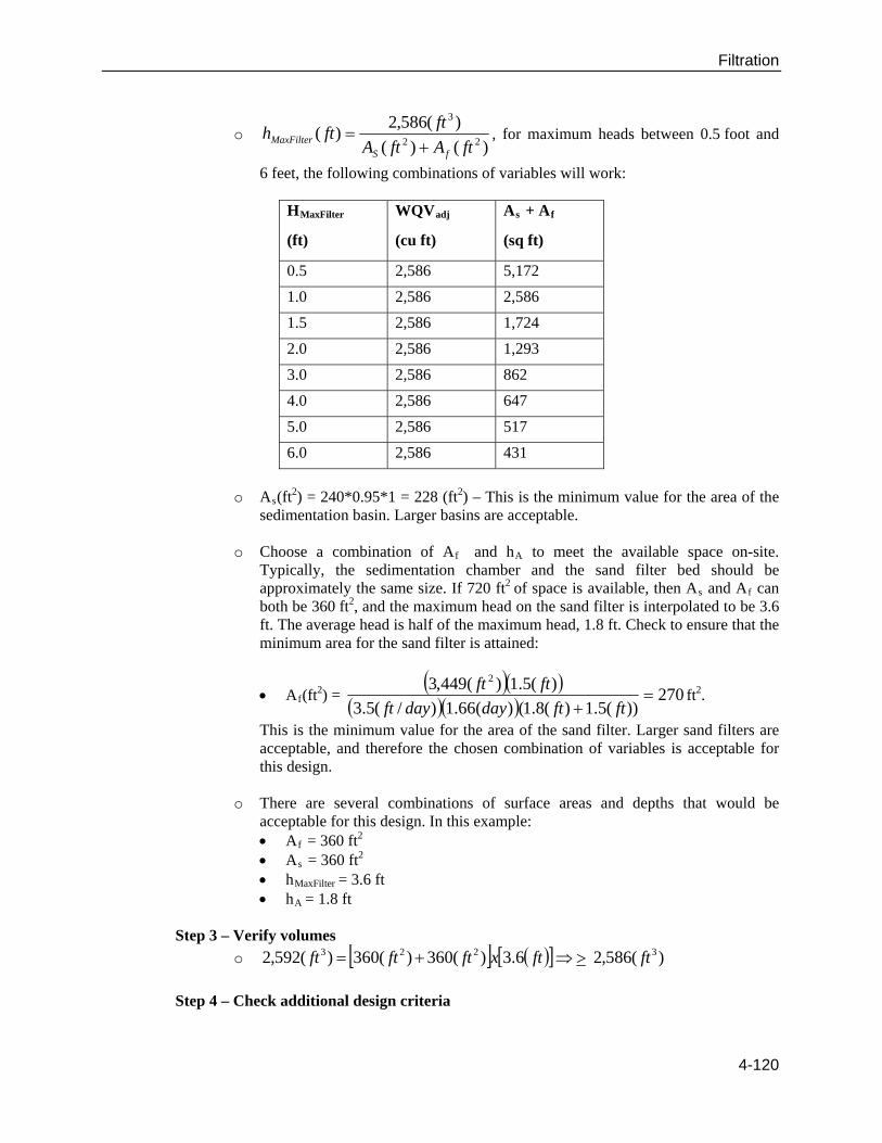
o )()(
)(586,2)(
22
3
ftAftA
ftfth
fSMaxFilter
, for maximum heads between 0.5 foot and
6 feet, the following combinations of variables will work:
HMaxFilter
(ft)
WQVadj
(cu ft)
As + Af
(sq ft)
0.5 2,586 5,172
1.0 2,586 2,586
1.5 2,586 1,724
2.0 2,586 1,293
3.0 2,586 862
4.0 2,586 647
5.0 2,586 517
6.0 2,586 431
o As(ft
2) = 240*0.95*1 = 228 (ft2) – This is the minimum value for the area of the sedimentation basin. Larger basins are acceptable.
o Choose a combination of Af and hA to meet the available space on-site.
Typically, the sedimentation chamber and the sand filter bed should be approximately the same size. If 720 ft2 of space is available, then As and Af can both be 360 ft2, and the maximum head on the sand filter is interpolated to be 3.6 ft. The average head is half of the maximum head, 1.8 ft. Check to ensure that the minimum area for the sand filter is attained:
Af(ft2) =
270
))(5.1)(8.1()(66.1)/(5.3
)(5.1)(449,3 2
ftftdaydayft
ftftft2.
This is the minimum value for the area of the sand filter. Larger sand filters are acceptable, and therefore the chosen combination of variables is acceptable for this design.
o There are several combinations of surface areas and depths that would be
acceptable for this design. In this example: Af = 360 ft2 As = 360 ft2 hMaxFilter = 3.6 ft hA = 1.8 ft
Step 3 – Verify volumes
o )(586,26.3)(360)(360)(592,2 3223 ftftxftftft
Step 4 – Check additional design criteria
4-120
Filtration
o Because this is an underground project, sufficient access must be provided to
facilitate cleaning and maintenance.
Treatment
Treatment design features help enhance the ability of a stormwater-management practice to remove pollutants. In filtering systems, designers should provide at least 75 percent of the water quality volume in the practice, including both the sand chamber and the sediment chamber. The filter bed should be sized using Darcy’s Law, which relates the velocity of fluids to the hydraulic head and the coefficient of permeability of a medium. In sand filters, designers should select a medium-sized sand as the filtering medium.
Media Requirements
The media in the sand filter shall be cleaned, washed, coarse masonry sand such as ASTM C33. The sand particles shall be less than 2 mm average diameter. The filter bed shall have a minimum depth of 18 inches, with a minimum depth of sand above the drainage pipe of 12 inches. The medium for organic filtering can be a combination of 50% peat and 50% sand or compost-only filter, both with a minimum depth of 18 inches. The peat/sand filter should be installed over a 6-inch layer of sand.
Conveyance
Conveyance of stormwater runoff into and through the filter should be conducted safely and in a manner that minimizes erosion potential. Ideally, some stormwater treatment can be achieved during conveyance to and from the filter. Since filtering practices are usually designed as “off-line” systems, meaning that they have the smaller water quality volume diverted to them only during larger storms, using a flow splitter, which is a structure that bypasses larger flows to the storm drain system or to a stabilized channel. One exception is the perimeter filter. In this design, all flows enter the system, but larger flows overflow to an outlet chamber and are not treated by the practice. All filtering practices, with the exception of exfilter designs, are designed with an underdrain below the filtering bed. An underdrain is a perforated pipe system in a gravel bed, installed on the bottom of filtering practices and used to collect and remove filtered runoff.
Drainage Considerations
The sand filter chamber shall drain completely within 40 hours. The length of time that it takes to drain the media of a filter is controlled by the infiltration rate of the media (or possibly the infiltration rate of the in situ soil if the system is designed as an infiltration type system).
Landscaping
Landscaping can add to both the aesthetic value and the treatment ability of stormwater practices. In sand filters, little landscaping is generally used on the practice, although surface sand filters and organic media filters may be designed with a grass cover on the surface of the filter. In all filters, designers need to ensure that the contributing drainage has dense vegetation to reduce sediment loads to the practice.
Common Problems When the filtering capacity diminishes substantially (e.g., when water ponds on the surface for more than 40 hours), remedial actions must be taken. One possible cause of this problem is that collection pipe systems have become clogged. Annual flushing of pipe clean-outs is recommended to facilitate unclogging of the pipes without disturbing
4-121
Filtration
the filter area. If the water still ponds above the sand filter bed for more than 40 hours, the top few inches of media should be removed and replaced with fresh media. The removed sediments should be disposed of in an acceptable manner (e.g., landfill). If the problem still persists, more extensive rebuilding is required.
Maintenance Typical annual maintenance requirements are:
● Check to see that the filter bed is clean of sediments, and the sediment chamber is no more than one-half full of sediment; remove sediment if necessary.
● Make sure that there is no evidence of deterioration, sailing, or cracking of concrete.
● Inspect grates (if used). ● Inspect inlets, outlets, and overflow spillway to ensure good condition and no
evidence of erosion. ● Repair or replace any damaged structural parts. ● Stabilize any eroded areas. ● Ensure that flow is not bypassing the facility.
4-122
Filtration
Vegetated Filter Strip
Practice Description
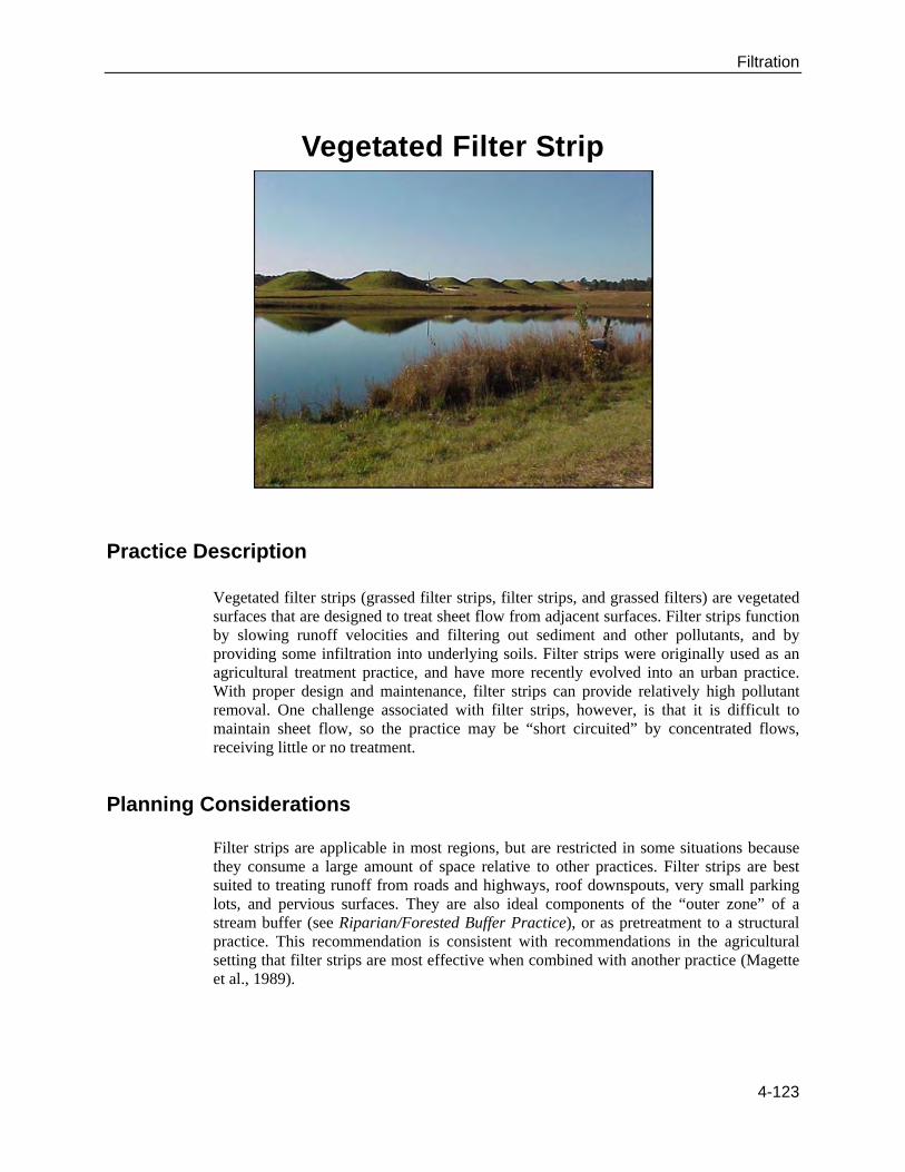
Vegetated filter strips (grassed filter strips, filter strips, and grassed filters) are vegetated surfaces that are designed to treat sheet flow from adjacent surfaces. Filter strips function by slowing runoff velocities and filtering out sediment and other pollutants, and by providing some infiltration into underlying soils. Filter strips were originally used as an agricultural treatment practice, and have more recently evolved into an urban practice. With proper design and maintenance, filter strips can provide relatively high pollutant removal. One challenge associated with filter strips, however, is that it is difficult to maintain sheet flow, so the practice may be “short circuited” by concentrated flows, receiving little or no treatment.
Planning Considerations Filter strips are applicable in most regions, but are restricted in some situations because they consume a large amount of space relative to other practices. Filter strips are best suited to treating runoff from roads and highways, roof downspouts, very small parking lots, and pervious surfaces. They are also ideal components of the “outer zone” of a stream buffer (see Riparian/Forested Buffer Practice), or as pretreatment to a structural practice. This recommendation is consistent with recommendations in the agricultural setting that filter strips are most effective when combined with another practice (Magette et al., 1989).
4-123
Filtration
Urban Areas
Urban areas are densely developed urban areas in which little pervious surface exists. Filter strips are impractical in ultra-urban areas because they consume a large amount of space.
Stormwater Hot Spots
Stormwater hot spots are areas where land use or activities generate highly contaminated runoff, with concentrations of pollutants in excess of those typically found in stormwater. A typical example is a gas station. Filter strips should not receive hot-spot runoff, because the practice encourages infiltration. In addition, it is questionable whether this practice can reliably remove pollutants. Therefore, it should definitely not be used as the sole treatment of hot-spot runoff.
Stormwater Retrofit
A stormwater retrofit is a stormwater-management practice (usually structural) put into place after development has occurred, to improve water quality, protect downstream channels, reduce flooding, or meet other specific objectives. Filter strips are generally a poor retrofit option because they consume a relatively large amount of space and cannot treat large drainage areas.
Design Criteria
Siting Considerations
In addition to the restrictions and modifications to adapting filter strips to different regions and land uses, designers need to ensure that this management practice is feasible at the site in question. The following section provides basic guidelines for siting filter strips.
Recommended distances (for the location of the filter strip from surface waters) depend on the applicable rules:
– An engineered filter strip may not be placed within either inner zone of a riparian buffer. However, it may be placed within a stormwater setback/buffer.
– Wetlands will be allowed within the filter strip only on a case-by-case basis.
Drainage Area
Typically, filter strips are used to treat very small drainage areas. The limiting design factor, however, is not the drainage area the practice treats but the length of flow leading to it. As stormwater runoff flows over the ground’s surface, it changes from sheet flow to concentrated flow. Rather than moving uniformly over the surface, the concentrated flow forms rivulets that are slightly deeper and cover less area than the sheet flow. When flow concentrates, it moves too rapidly to be effectively treated by a grassed filter strip. (The
4-124
Filtration
use of a level spreader may be helpful in cases with concentrated flows.) Furthermore, this concentrated flow can lead to scouring. As a rule, flow concentrates within a maximum of 75 feet for impervious surfaces and 150 feet for pervious surfaces (CWP, 1996). Using this rule, a filter strip can treat one acre of impervious surface per 580-foot length.
Slope
Filter strips should be designed on slopes between 2 and 6 percent. Greater slopes than this would encourage the formation of concentrated flow. Except in the case of very sandy or gravelly soil, runoff would pond on the surface of slopes flatter than 2 percent, creating potential mosquito-breeding habitat.
Soils /Topography
Filter strips should not be used on soils with high clay content, because they require some infiltration for proper treatment. Very poor soils that cannot sustain a grass cover crop are also a limiting factor.
Groundwater
Filter strips should be separated from the groundwater by between 2 and 4 ft to prevent contamination and to ensure that the filter strip does not remain wet between storms.
Design Considerations
Filter strips appear to be a minimal design practice because they are basically no more than a grassed slope. However, some design features are critical to ensure that the filter strip provides some minimum amount of water quality treatment.
A pea gravel diaphragm should be used at the top of the slope. The pea gravel diaphragm (a small trench running along the top of the filter strip) serves two purposes. First, it acts as a pretreatment device, settling out sediment particles before they reach the practice. Second, it acts as a level spreader, maintaining sheet flow as runoff flows over the filter strip.
The filter strip should be designed with a pervious berm of sand and gravel at the toe of the slope. This feature provides an area for shallow ponding at the bottom of the filter strip. Runoff ponds behind the berm and gradually flows through outlet pipes in the berm. The volume ponded behind the berm should be equal to the water quality volume. The water quality volume is the amount of runoff that will be treated for pollutant removal in the practice. Typical water quality volumes are the runoff from a 1-inch storm or ½-inch of runoff over the entire drainage area to the practice.
The filter strip should be at least 25 feet long to provide water quality treatment.
Designers should choose a grass that can withstand relatively high-velocity flows and both wet and dry periods.
Both the top and toe of the slope should be as flat as possible to encourage sheet flow and prevent erosion.
4-125
Filtration
4-126
Common Problems
Filter strips have several limitations related to their performance and space consumption:
The practice has not been shown to achieve high pollutant removal.
Filter strips require a large amount of space, typically equal to the impervious area they treat, making them often infeasible in urban environments where land prices are high.
If improperly designed, filter strips can allow mosquitoes to breed.
Proper design requires a great deal of finesse, and slight problems in the design, such as improper grading, can render the practice ineffective in terms of pollutant removal.
Maintenance Immediately after the filter strip is established, grass will be watered twice
weekly, if needed, until the plants become established (commonly six weeks).
Once a year, the filter strip will be reseeded to maintain a dense growth of vegetation
Stable groundcover will be maintained in the drainage area to reduce the sediment load to the vegetation.
Every two weeks during the growing season, the filter strip will be mowed. Turf grass should not be cut shorter than 3 to 5 inches and may be allowed to grow as tall as 12 inches depending on aesthetic requirements (NIPC, 1993). Forested filter strips do not require this type of maintenance.
Once a year, the soil will be aerated if necessary.
Once a year, soil pH will be tested and lime will be added if necessary.