bios setup program - viglen limited -...
TRANSCRIPT

43
BIOS Setup Program The Setup program is for viewing and changing the BIOS settings for a computer. Pressing the F2 key after the POST memory test begins and before the operating system boot begins accesses setup. In Table 9 the menus available from the menu bar at the top of the Setup screen are briefly explained.
Table 9 Setup Menu Screen Description Main Allocates resources for hardware components. Advanced Specifies advanced features available through the
chipset. Security Specifies passwords and security features. Server Specifies System Management and Console
Redirection options. Boot Specifies boot options. Exit Saves or discards changes to the Setup program
and default setting options. Table 10 shows the function keys available for use in the menu screens.
Table 10 Setup Key Description F1 Brings up a help screen for the current item. Esc Exits the menu. ←←←← or →→→→ Selects a different menu screen.
↑↑↑↑ and ↓↓↓↓ Moves the cursor up or down. Page Up and Page Down
Moves cursor to top or bottom of the window.
- Selects the previous value for a field.
+ Selects the next value for a field.
F9 Load the default configuration values for the whole BIOS.
F10 Save the current values and exits Setup.
Return (↵↵↵↵) Executes command or selects the submenu.

44
Main Menu This is what the main menu BIOS screen looks like. This is the first screen you will be presented with.
PhoenixBIOS Setup Utility
Main Advanced Security Server Boot Exit
System Time: [ 8:37:10 ]Item Specific helpSystem Date: [25/11/1999]
Legacy Diskette A: [1.44/1.25 MB 3½”]
<Tab>, <Shift-Tab>, or<Enter> selects field.
Legacy Diskette B: [Disable]
�Primary IDE Master
�Primary IDE Slave
�Secondary IDE Master
�Secondary IDE Slave
�Keyboard FeaturesProcessor Setting
Language: [English US]
F1 Help ↑=↓ Select Item +/- Change Values F9 Setup DefaultsEsc Exit ←→ Select menu Enter Select sub-menu F10 Save & Exit
�
[None]
[None]
[None]
[None]
Figure 9 Table 11 Feature Options Description System Time Hour, minute, and
second Specifies the current time.
System Date Month, day, and year
Specifies the current date.
Legacy Diskette A:
•= Disabled •= 360 KB, 5¼″ •= 1.2 MB, 5¼″ •= 720 KB, 3½″ •= 1.44/1.25 MB,
3½″″″″ (default) •= 2.88 MB, 3½″
Specifies the capacity and physical size of diskette drive A.
Legacy Diskette B:
As above apart from Disable is the default
As above but for drive B.
Primary IDE Master, submenu
No options Reports type of connected IDE device. When selected, displays the Primary IDE Master submenu.

45
Table 11 continued Primary IDE Slave, submenu
No options Reports type of connected IDE device. When selected, displays the Primary IDE Slave submenu.
Secondary IDE Master, submenu
No options Reports type of connected IDE device. When selected, displays the Secondary IDE Master submenu.
Secondary IDE Slave, submenu
No options Reports type of connected IDE device. When selected, displays the Secondary IDE Slave submenu.
Keyboard Features
No Options When selected, displays the Keyboard features submenu.
Processor Speed
No Options When selected, displays the Processor Speed features submenu.
Language English (US) Selects the default language used by the BIOS.

46
IDE Device Configuration Submenus This submenu is for configuring IDE devices, including:
•= Primary IDE master •= Primary IDE slave •= Secondary IDE master •= Secondary IDE slave Table 12 Feature Options Description Type •= Auto (default)
•= None •= CD-ROM •= IDE Removable •= ATAPI
Removable •= User
Specifies the IDE configuration mode for IDE devices. User allows the cylinders, heads, and sectors fields to be changed. Auto automatically fills in the values for the cylinders, heads, and sector fields.
Cylinders 0 to 65535 Specifies number of disk cylinders.
Heads 1 to 16 Specifies number of disk heads. Sectors 0 to 63 Specifies number of disk sectors. Maximum Capacity No options Reports the maximum capacity
for the hard disk. Value calculated from number of cylinders, heads, and sectors.
LBA Format No options Total Sectors No options This field is for information only Maximum Capacity No options This field is for information only Multi-Sector Transfers
•= Disabled (default)
•= 2 Sectors •= 4 Sectors •= 8 Sectors •= 16 Sectors
Specifies number of sectors per block for transfers from the hard drive to memory. Check the hard drive’s specifications for optimum setting.

47
Table 12 continued
LBA Mode Control •= Disabled (default)
•= Enabled
Enables or disables logical block addressing (LBA) in place of the Cylinders, Heads, and Sectors fields.
! CAUTION Changing the LBA Mode Control after a hard drive has been formatted can corrupt data on the drive.
32 Bit I/O •= Disabled (default)
•= Enabled
Enables or disables the 32 Bit input and output for the device.
Transfer Mode •= Standard •= Fast PIO 1 •= Fast PIO 2 •= Fast PIO 3 •= Fast PIO 4
(default) •= FPIO3 / DMA1 •= FPIO4 / DMA2
Specifies method for transferring data between the hard drive and system memory.
Ultra DMA •= Disabled (default)
•= Mode 0 •= Mode 1 •= Mode 2
Specifies the ultra DMA mode for the hard drive.
48
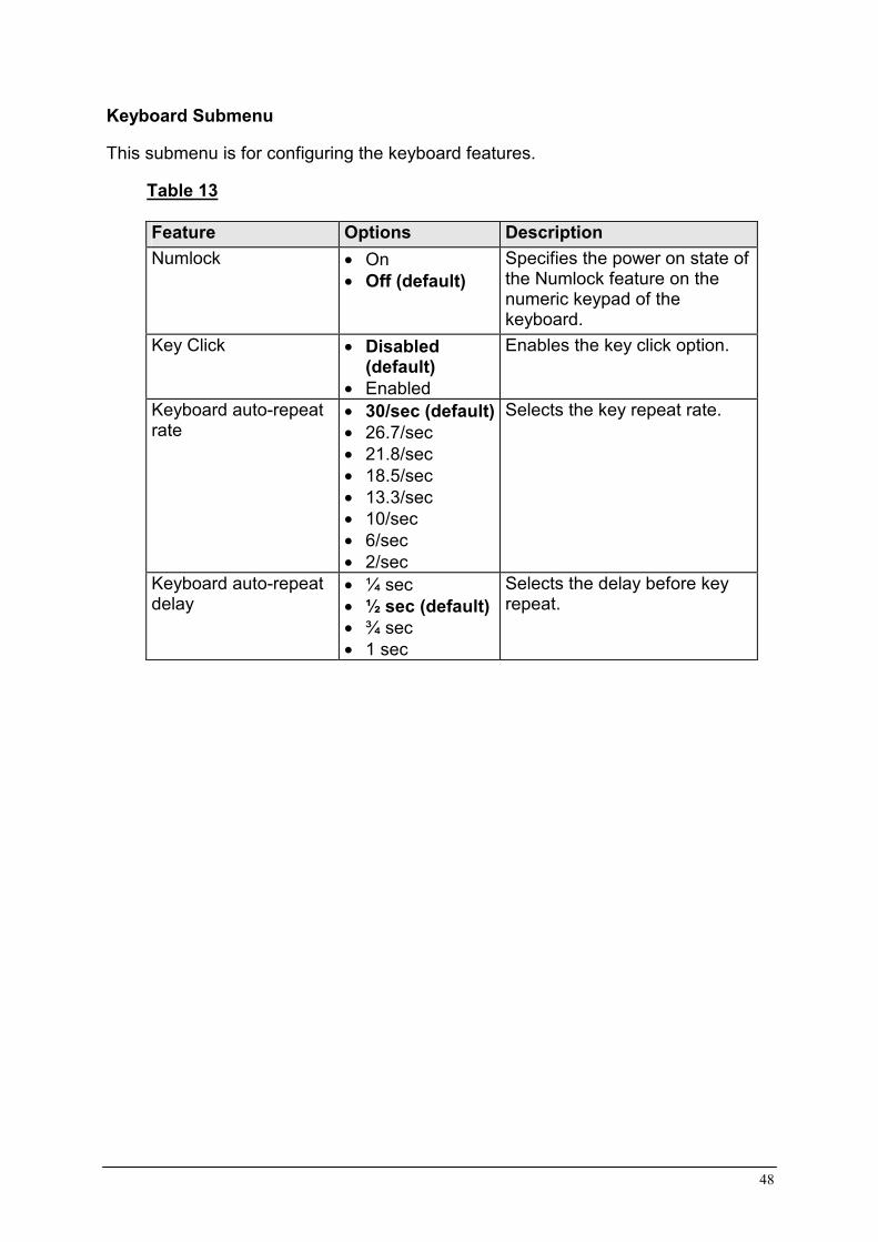
Keyboard Submenu This submenu is for configuring the keyboard features.
Table 13 Feature Options Description Numlock •= On
•= Off (default) Specifies the power on state of the Numlock feature on the numeric keypad of the keyboard.
Key Click •= Disabled (default)
•= Enabled
Enables the key click option.
Keyboard auto-repeat rate
•= 30/sec (default)•= 26.7/sec •= 21.8/sec •= 18.5/sec •= 13.3/sec •= 10/sec •= 6/sec •= 2/sec
Selects the key repeat rate.
Keyboard auto-repeat delay
•= ¼ sec •= ½ sec (default)•= ¾ sec •= 1 sec
Selects the delay before key repeat.

49
Processor Settings Submenu This submenu is for configuring the keyboard features.
Table 14 Feature Options Description CPU Speed Setting •= 350
•= 400 •= 450 •= 500 •= 550 •= 600 •= 650 •= 700
Sets the speed for the installed processor(s).
! CAUTION Attempting to set the higher that the proper speed for the installed processor(s) may cause damages to the processor(s) or prevent the server from booting until the CMOS clear is performed.
CPU POST Speed Settings
No options This field is for information only
Processor Retest •= Yes •= No
Yes tells BIOS to clear the historical processor status and retest all processors on the next boot. BIOS automatically resets to No in next boot.
Memory Cache •= Enabled •= Disabled
Enables processor cache.
Processor 1 Stepping ID
No options This field is for information only
Processor 1 L2 Cache Size
No options This field is for information only
Processor 2 Stepping ID
No options This field is for information only
Processor 2 L2 Cache Size
No options This field is for information only
50
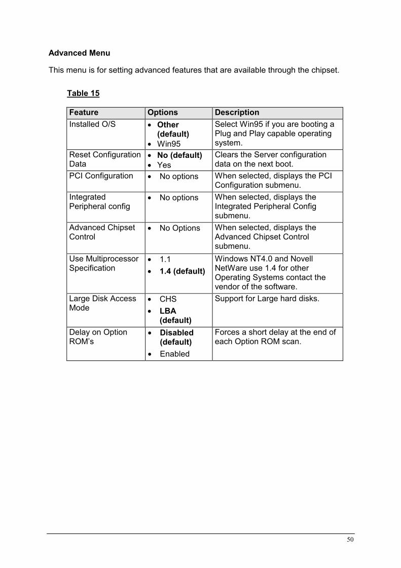
Advanced Menu This menu is for setting advanced features that are available through the chipset.
Table 15 Feature Options Description Installed O/S •= Other
(default) •= Win95
Select Win95 if you are booting a Plug and Play capable operating system.
Reset Configuration Data
•= No (default) •= Yes
Clears the Server configuration data on the next boot.
PCI Configuration •= No options When selected, displays the PCI Configuration submenu.
Integrated Peripheral config
•= No options When selected, displays the Integrated Peripheral Config submenu.
Advanced Chipset Control
•= No Options When selected, displays the Advanced Chipset Control submenu.
Use Multiprocessor Specification
•= 1.1 •= 1.4 (default)
Windows NT4.0 and Novell NetWare use 1.4 for other Operating Systems contact the vendor of the software.
Large Disk Access Mode
•= CHS •= LBA
(default)
Support for Large hard disks.
Delay on Option ROM’s
•= Disabled (default)
•= Enabled
Forces a short delay at the end of each Option ROM scan.

51
PCI Configuration Submenu This menu allows the selection of submenus to manually configure PCI device slots, and the on-board SCSI ROM. PCI Device Embedded SCSI Devices Submenu
Table 16 Feature Options Description Option ROM scan •= Enabled
(default) •= Disabled
Initialize device expansion ROM.
Enable Master •= Enabled (default)
•= Disabled
Enable the SCSI device as a PCI bus master.
Latency Timer •= Default •= 0020h •= 0040h
(default) •= 0060h •= 0080h •= 00A0h •= 00C0h •= 00E0h
Select the time slot allotted to the bus mastering in PCI bus clocks.
! CAUTION Do not change this setting unless you fully understand the priority of this device on the PCI bus.
PCI Device, slot 1 - 6 Submenu
Table 17 Feature Options Description Enable Master •= Enabled
(default) •= Disabled
Enable the selected device as a PCI bus master.
Latency Timer •= Default •= 0020h •= 0040h
(default) •= 0060h •= 0080h •= 00A0h •= 00C0h •= 00E0h
Select the time slot allotted to the bus mastering in PCI bus clocks.
! CAUTION Do not change this setting unless you fully understand the priority of this device on the PCI bus.

52
Integrated Peripheral Configuration Submenu This submenu is for the configuring the computer peripherals.
Table 18 Feature Options Description Com1 •= Disabled
•= Enabled (default)•= Auto •= OS Controlled
Auto forces BIOS to Configure the port. OS Controlled forces the OS to configure the port.
Base I/O address
•= 3F8 (default) •= 2F8 •= 3E8 •= 2E8
Options for Base I/O address for both of the serial ports.
Interrupt •= IRQ 3 •= IRQ 4 (default)
The interrupt settings for the two serial ports.
Com2 •= Disabled •= Enabled (default)•= Auto •= PnP OS
Auto forces BIOS to Configure the port. PnP OS forces the OS to configure the port.
Base I/O address
•= 3F8 •= 2F8 (default) •= 3E8 •= 2E8
Options for Base I/O address for both of the serial ports.
Interrupt •= IRQ 3 (default) •= IRQ 4
The interrupt settings for the two serial ports.
Parallel port •= Disabled •= Enabled (default)•= Auto •= PnP OS
Auto forces BIOS to Configure the port. OS Controlled forces the OS to configure the port.
Mode •= Output Only •= Bi-directional •= EPP •= ECP (default)
Selects the mode for the parallel port.
Base I/O address
•= 378 (default) •= 278
Select the base I/O address setting for the parallel port.
Interrupt •= IRQ 5 •= IRQ 7 (default)
Select the interrupt setting for the parallel port.
DMA channel •= DMA 1 (default) •= DMA 3
Set the DMA channel for the parallel port. Only for ECP mode.
Floppy disk controller
•= Disabled •= Enabled (default)
Configures the floppy disk controller.

53
Advanced Chipset Control Submenu This submenu is for setting advanced options that affect the running of the chipset.
Table 19 Feature Options Description 640-768K Memory Region
•= Disabled •= Enabled (default)
Enabled forwards ISA Master and DMA cycles to the PCI bus. Disabled forwards these cycles to memory.
Delayed Transaction
•= Disabled •= Enabled (default)
Enables the delayed transaction mechanism when the PIIX4e is the target of a PCI transaction.
Passive Release •= Disabled •= Enabled (default)
Enables the passive release mechanism on the PHOLD# signal when the PIIX4 is a PCI Master.

54
Security Menu You can make the following selections on the Security Menu itself. Enabling the Supervisor Password field requires a password for entering Setup. The passwords are not case-sensitive.
Table 20 Feature Options Description User Password is
•= Clear (Default)•= Set
Status only; user cannot modify. Once set, this can be disabled by setting it to a null string, or by clearing password jumper on server board.
Supervisor Password is
•= Clear (Default)•= Set
Status only; user cannot modify.
Set User password
Press Enter When the <Enter> key is pressed, you are prompted for a password; press ESC key to abort. Once set, this can be cleared by setting it to a null string, or by clearing password jumper on server board.
Set Supervisor password
Press Enter When the <Enter> key is pressed, you are prompted for a password; press ESC key to abort. Once set, this can be cleared by setting it to a null string, or by clearing password jumper on server board.
Password on Boot
•= Disabled (default)
•= Enabled
If enabled will ask for a password when booting up.
Fixed disk boot sector
•= Normal (default)
•= Write Protect
Write Protects boot sector on hard disk to protect against viruses.
Secure mode timer
•= Disabled •= 1 min (default)•= 2 min •= 5 min •= 10 min •= 20 min •= 1 hr •= 2 hr
Set’s the time of keyboard and mouse inactivity before the secure mode activates. A password must be entered for the secure mode to work.
Secure mode hot key
•= Nothing (default)
•= A, B, …, – Z
Any letter or number can be entered. Ctrl-Alt-? (? Being the chosen key) will now start the secure mode.

55
Table 20 continued
Secure mode Boot
•= Disabled (default)
•= Enabled
When enabled the system boots up and will go directly into secure mode, and the password must be entered to start the machine.
Video Blanking •= Disabled (default)
•= Enabled
Blanks the video when secure mode activates.
Floppy Write Protect
•= Disabled (default)
•= Enabled
Write protects the floppy drive when secure mode activates. Requires password to restore floppy writes.
Front Panel Lockout
•= Disabled (default)
•= Enabled
When secure mode is activated, the reset and power switches are locked. You must enter a password to unlock the system. Cannot be enabled unless at least one password is enabled.

56
Server Menu
This menu is for setting up server and system management features.
Table 21 Feature Options Description System Management
•= No options When selected, displays the System management submenu.
Console Redirection •= No options When selected, displays additional menus for configuring Remote console interface.
PEP Management No Options When selected, displays additional menus for configuring PEP.
Enable Sleep Button
•= Disabled (default)
•= Enabled
PCI IRQ’s to IO-APIC mapping
•= Disabled (default)
•= Enabled
Enabled - BIOS can describe all 24 IO APIC pins in the MP table for PCI interrupts. Not all MP operating systems and drivers can understand this description of the interrupts in the MP table. Disabled - BIOS will only use 16 IO APIC pins in the MP table for PCI interrupts. All PCI interrupts are routed to a standard ISA IRQ pins on IO APIC. All operating systems will work with standard ISA IRQ entries.
Processor Retest •= No (default) •= Yes
If yes is selected then the BIOS will rest all historical info on the processors and retest them.
Assert NMI on PERR
•= Disabled (default)
•= Enabled
Enabled generates an NMI on a parity error (PERR). To activate this feature, the system error (SERR) option must be enabled.
Assert NMI on SERR
•= Disabled •= Enabled
(default)
Enabled generates an NMI on SERR.

57
System Management Submenu Table 22 Feature Options Description Server Management Info
No options This option will allow you to view the system serial & part numbers, etc.
System Event Logging
•= Disabled •= Enabled
(default)
This option allows the user to log the system events.
Clear Event Log •= No (default) •= Yes
This will clear the system event log when Yes is selected.
EMP Password Switch
•= Disabled (default)
•= Enabled
This field enables or disables EMP Password
EMP Password [A..Z, 0..9] This field only shows up when the EMP password switch is enabled. Entering a password and pressing return will send the password immediately to the BMC. If a beep is heard the password was not accepted. If no password is entered, anyone has access to the server through the EMP Console.
EMP ESC Sequence
+++ Sets the escape sequence for the modem being used for EMP. This will force the modem to command mode. This is only used if the EMP direct connect/modem mode is set to modem.
EMP Hangup Line String
ATH Sets the Hangup Line Sequence for the modem being used for EMP. Used in EMP modem mode.
Modem Init String AT&F0S0=1S14=0&D
Sets the initialization string for the modem being used for EMP. Used in EMP modem mode. This field is only 16 characters long. The High Modem Init String field is a continuation of the Modem Init string so you can enter in another 4 characters.

58
Table 22 continued
High Modem Init String
0 This is a continuation of the Modem Init String. When 16 characters are typed into the Modem Init String field, this field will appear to allow another 4 characters to be typed in.
EMP Access Mode •= Pre-Boot Only(Default)
•= Always Active•= Disabled
This option allows you to choose if the EMP will be released after boot or not.
EMP Restricted Mode Access
•= Disabled (Default)
•= Enabled
EMP Direct Connect/Modem Mode
•= Direct Connect
•= Modem Mode (Default)
This field allows you to choose whether you access the EMP via a external modem link or a direct RS-232 serial cable

59
Console Redirection Submenu Table 23
Feature Options Description Com Port address •= Disabled (default)
•= 3F8 •= 2F8 •= 3E8
When enabled, console redirection uses the I/O port specified. 3F8 - typically is COM1 2F8 - typically is COM2 All keyboard/mouse and video will be directed to this port. This is designed to be used only under DOS in text mode.
IRQ # No Options This field in information onlyBaud Rate •= 9600
•= 19.2K (default) •= 38.4K •= 115.2K
Sets the Baud Rate to be used.
Flow Control •= No flow Control •= CTS/RTS •= XON/XOFF •= CTS/RTS + CD
(default)
None disallows flow control.CTS/RTS is hardware-flow control. XON/XOFF is software-flow control. CTS/RTS +CD is hardware plus carrier-detect flow control.

60
PEP Management Submenu Table 24
Feature Options Description PEP Filter Events No options Enters submenu. PEP Enable •= Disabled
(default) •= Enabled
Enables Platform Event Paging.
PEP Blackout Period
[0…9] Sets the amount of time between pages in minutes. Valid range is from 0 to 10.
PEP Page String Sets the string used to page you. Generally this is the attention command for your modem, followed by the number of your paging service, followed by the message you want to appear on your pager, followed by a modem hangup command. Use commas for 1second pauses. This field is only 16 characters long. The 16-31, 32-47, and 48-63 fields are a continuation of the PEP Page String Field so you can enter in another 48 characters for 64 characters total.
16-31 This is a continuation of the PEP Page String Field. When 16 characters are typed into the Modem Init String field, this field will appear to allow another 16 characters to be typed in.
32-47 This is a continuation of the PEP Page String Field. When 16 characters are typed into the Block #1 field, this field will appear to allow another 16 characters to be typed in.
48-63 This is a continuation of the PEP Page String Field. When 16 characters are typed into the Block #2 field, this field will appear to allow another 16 characters to be typed in.
Send Test Page Press Enter Send Test Page Now
To send a test page, select "Send Test Page Now" from the popup menu.

61
PEP Filter Submenu Table 25
Feature Options Description PEF Enable
•= Disabled (default)
•= Enabled
Enables the Platform Event Filtering. If this is enabled, and one of the events you enable below occurs, the server will page you using the Page String (NV) information.
Temperature Sensor
•= Disabled (default)
•= Enabled
Voltage Sensor •= Disabled (default)
•= Enabled
Fan Sensor •= Disabled (default)
•= Enabled
Chassis Sensor •= Disabled (default)
•= Enabled
Power Supply •= Disabled (default)
•= Enabled
BIOS (SMI Handle)
•= Disabled (default)
•= Enabled
BIOS POST •= Disabled (default)
•= Enabled
FRB Sensor •= Disabled (default)
•= Enabled
Fatal NMI •= Disabled (default)
•= Enabled
Watchdog Timer Reset
•= Disabled (default)
•= Enabled
System Restart Disabled (default) Enabled

62
Boot Menu
Table 26 Feature Options Description Boot-time Diagnostic screen
•= Disabled (default)•= Enabled
Extended RAM step
•= 1MB •= 1KB •= Every Location •= No memory test
1MB tests extended memory once per MegaByte 1KB tests extended memory once per KiloByte Every Location Tests all extended memory No Memory test No extended memory is tested
BIOS boot spec support
•= Enabled (default) •= Limited
Boot device Priority
No options This option will allow you to enter the Boot Device Priority Submenu.
Hard Drive No options This option will allow you to enter the Hard Drive Submenu.
Removable Devices
No options This option will allow you to enter the Removable Devices Submenu.
Boot Device Priority
Table 27 Boot Priority Options Description 1 Removable
Devices Attempts to boot from a removable media device.
2 Hard Drive Attempts to boot from a hard drive device.
3 ATAPI CD-ROM Drive
Attempts to boot from an ATAPI CD-ROM drive.
4 LANDesk Service Agent II
Attempts to boot from the local area network.

63
Hard Drive Submenu
Table 28 Options Description •= Installed hard
drive •= Other Bootable
Devices
Specifies the boot sequence for the hard drives attached to the computer. To specify boot sequence: 1. Select the boot device with <↑> or <↓>. 2. Press <+> to move the device up the list or <-> to
move the device down the list. The operating system assigns a drive letter to each device in the order listed. Changing the order of the devices changes the drive lettering.
Removable Devices Submenu
Table 29 Options Description •= Legacy Floppy
Drives
Specifies the boot sequence for removable devices attached to the computer. To specify boot sequence: 1. Select the boot device with <↑> or <↓>. 2. Press <+> to move the device up the list or <-> to
move the device down the list.
Exit Menu
Table 30 Feature Description Exit Saving Changes
Exits after writing all modified Setup item values to NVRAM.
Exit Discarding Changes
Exits leaving NVRAM unmodified.
Load Setup Defaults Loads values of all Setup items from previously saved custom defaults.
Load Custom Defaults
Loads default values for all Setup items.
Save Custom Defaults
Saves present Setup values to custom defaults.
Discard Changes Read previous values of all Setup items from NVRAM.Save Changes Writes all Setup item values to NVRAM.

64
Upgrading / Recovering the BIOS This chapter describes how to upgrade the BIOS and how to recover the BIOS if an upgrade fails. Preparing for the Upgrade Before you upgrade the BIOS, prepare for the upgrade by recording the current BIOS settings and obtaining the upgrade utility. Obtaining the Upgrade Utility You can upgrade to a new version of the BIOS using the new BIOS files and the BIOS upgrade utility, iFLASH.EXE. You can obtain the BIOS upgrade file and the iFLASH.EXE utility through Viglen’s World Wide Web site: http://www.viglen.com.
NOTE: Please review the instructions distributed with the upgrade utility before attempting a BIOS upgrade. This upgrade utility allows you to:
•= Upgrade the BIOS in flash memory. •= Update the language section of the BIOS.
The following steps explain how to upgrade the BIOS. Please follow all the step’s accurately.
Recording the Current BIOS Settings
1. As the computer boots, write down the BIOS identifier (version number) so a check can be made later to make sure the upgrade was successful.
2. Boot the computer and press <F2> when you see the message: Press <F2> Key if you want to run SETUP
3. Write down the current settings in the BIOS Setup program.
NOTE: Do not skip step 3. You will need these settings to configure your computer at the end of the procedure.

65
Creating a Bootable Floppy Diskette
1. Use a DOS or Windows 95/98 system to create the floppy disk. 2. Place an unformatted floppy diskette in the floppy drive and format the
floppy using the /S option. example: "Format a: /s" 3. Alternatively, place a formatted floppy in the floppy drive and use the "sys"
command. example: "sys a:" 4. Press <Enter>
Creating the BIOS Upgrade Floppy Diskette The BIOS upgrade file is a compressed self-extracting archive that contains the files you need to upgrade the BIOS.
1. Copy the BIOS upgrade file to a temporary directory on your hard disk. 2. From the C:\ prompt, change to the temporary directory. 3. To extract the file, type the name of the BIOS upgrade file, for example:
BIOS_10.EXE and press <Enter> or double click on the icon with the mouse in Windows NT.
4. Read the LICENSE.TXT file, which contains the software license agreement and the README.TXT file, which contains the instructions for the BIOS upgrade.
5. Insert the bootable floppy disk into drive A. 6. Copy the extracted files to the floppy disk. 7. The floppy disk now holds the BIOS upgrade and recovery files.
Upgrading the BIOS
1. Boot the computer with the floppy disk in drive A. The BIOS upgrade utility screen appears.
2. Select Update Flash Memory from a File. 3. Select Update System BIOS. Press <Enter>. 4. Use the arrow keys to select the correct .bio (Should only be one) file.
Press <Enter>. 5. When the utility asks for confirmation that you want to flash the new BIOS
into memory, select Continue with Programming. Press <Enter>. 6. When the utility displays the message upgrade is complete, remove the
floppy disk. Press <Enter>. 7. As the computer boots, check the BIOS identifier (version number) to make
sure the upgrade was successful. 8. To enter the Setup program, press <F2> when you see the message:
Press <F2> Key if you want to run SETUP 9. For proper operation, load the Setup program defaults. To load the
defaults, press <F9>. 10. To accept the defaults, press <Enter>.
66
11. Set the options in the Setup program to the settings you wrote down before the BIOS upgrade.
12. To save the settings, press <F10>. 13. To accept the settings, press <Enter>. 14. Turn off the computer and reboot.
Recovering the BIOS It is unlikely that anything will interrupt the BIOS upgrade, however if an interruption occurs, the BIOS could be damaged. The following steps explain how to recover the BIOS if an upgrade fails. The following procedures use recovery mode for the Setup program.
NOTE: Because of the small amount of code available in the non-erasable boot block area, there is no video support. You will not see anything on the screen during the procedure. Monitor the procedure by listening to the speaker and looking at the floppy drive LED.
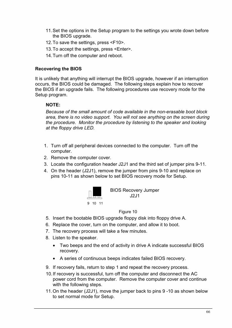
1. Turn off all peripheral devices connected to the computer. Turn off the computer.
2. Remove the computer cover. 3. Locate the configuration header J2J1 and the third set of jumper pins 9-11. 4. On the header (J2J1), remove the jumper from pins 9-10 and replace on
pins 10-11 as shown below to set BIOS recovery mode for Setup.
Figure 10 5. Insert the bootable BIOS upgrade floppy disk into floppy drive A. 6. Replace the cover, turn on the computer, and allow it to boot. 7. The recovery process will take a few minutes. 8. Listen to the speaker.
•= Two beeps and the end of activity in drive A indicate successful BIOS recovery.
•= A series of continuous beeps indicates failed BIOS recovery.
9. If recovery fails, return to step 1 and repeat the recovery process. 10. If recovery is successful, turn off the computer and disconnect the AC
power cord from the computer. Remove the computer cover and continue with the following steps.
11. On the header (J2J1), move the jumper back to pins 9 -10 as shown below to set normal mode for Setup.
9 10 11
BIOS Recovery JumperJ2J1

67
Figure 10.1
12. Replace the computer cover and reconnect the AC power cable; leave the
upgrade disk in drive A and turn on the computer. 13. Continue with the BIOS upgrade (see page 65 step 7).
BIOS Recovery JumperJ2J1
9 10 11

68
Chapter 5: Technical Information Note: This chapter is indented for experienced users only, and only to be used as a reference. Changes to or modify any of the components/ connectors listed herein can and will seriously damage your system, including the motherboard, CPU and/or any other hardware. SCSI Controller The embedded Adaptec AIC-7896 dual function SCSI controller provides both Ultra2 (LVDS) wide and Ultra wide SCSI interfaces as two independent PCI functions. PCI slot 4 is RAID-upgradeable, providing additional support for the ARO1130U2 RAIDport III controller by Adaptec. The SCSI bus is terminated on the server board with active terminators that cannot be disabled. The onboard device must always be at one end of the bus. The device at the end of the cable must be terminated. LVDS devices generally do not have termination capabilities. Non-LVDS devices generally are terminated through a jumper or resistor pack. The SCSI cable (Intel Part Number 745854-003) included with your server board (or integrator’s kit) has been modified to include active termination. The cable is capable of supporting both Ultra-2 and non-Ultra-2 SCSI devices. Proper termination of the SCSI bus is required for stable operation of SCSI devices. When attaching any SCSI device to the cable, verify that they are not terminated. This is usually a configurable option using a jumper or terminator block on the device. Check the documentation that came with your SCSI device to verify this option. Termination of the SCSI bus is implemented using the active termination on the server board along with the active termination at the end of the SCSI cable. IDE Controller IDE is a 16 bit interface for intelligent disk drives with disk controller electronics onboard. The PCI/ISA/IDE Accelerator, also known as PIIX4e, is a multifunction device on the server board that acts as a PCI based Fast IDE controller. The device controls:
•= PIO and IDE DMA/bus master operations •= Mode 4 timings •= Transfer rates up to 33 MB/s •= Buffering for PCI/IDE burst transfers •= Master/slave IDE mode •= Up to two devices per channel; two channels, IDE0 and IDE1
NOTE 18 inch maximum length of IDE cable on each channel: You can connect an IDE signal cable, up to a maximum of 18 inches each, to each IDE connector on the server board. Each cable can support two devices, one at the end of the cable and one 6 inches from the end of the cable.

69
Operating Systems and IDE hard drives Standard CHS is the translation that has been used for years. Its use limits IDE capacity to maximum of 528MB regardless of the size of the drive used. Logical Block mode overcomes the 528MB maximum size limitation imposed by the Standard CHS mode. It should be used only when the drive supports LBA (Logical Block Addressing), and the OS supports LBA, or uses the BIOS to access the disk. Extended CHS mode also overcomes the 528MB maximum size limitation imposed by Standard CHS mode. It can be used with drives, which are larger than 528MB that do not support LBA. Auto Detected allows the BIOS to examine the drive and determine the optimal mode. The first choice is to utilise Logical Block mode if it is supported by the drive. The second choice is to utilise Extended CHS mode if the drive topology allows. If neither of the above methods is possible, the Standard CHS mode is used. Different operating systems have different abilities regarding IDE translation mode. UNIX operating systems (as currently implemented) do not support either LBA or ECHS and must utilise the standard CHS method. UNIX can support drives larger than 528MB, but does so in its own way. OS/2 2.1 and OS/2 Warp can support LBA, ECHS or standard CHS methods. Note that LBA support may require a switch setting on an OS/2 driver in order to operate in that mode. OS/2 2.0 & Novel NetWare can support either ECHS or standard CHS methods. In order to use LBA with NetWare a driver that supports current parameters must be used. OS/2 2.0 does not support LBA. DOS & Windows can use LBA, ECHS or standard CHS methods. The '32-bit Disk Access' driver built into Windows WDCTRL.386 can only be used with the standard CHS method, to use either LBA or ECHS method and '32-bit Disk Access' an alternative .386 driver must be installed; this combination will also provide the best performance. If this driver is not installed and the drive fitted to the system supports Type F DMA on the ISA interface or Mode 3 on the PCI interface then higher performance will be achieved by NOT using '32-bit Disk Access'.

70
Network Controller The server board includes a 10BASE-T/100BASE-TX network solution based on the Intel 82559 single chip Fast Ethernet PCI Bus Controller. As a PCI bus master, the controller can burst data at up to 132 MB/s. The controller contains two receive and transmit FIFO buffers that prevent data overruns or underruns while waiting for access to the PCI bus. The controller has the following:
•= 32 bit PCI bus master interface (direct drive of bus), compatible with PCI Bus Specification, Revision 2.1
•= Chained memory structure with improved dynamic transmit chaining for enhanced performance
•= Programmable transmit threshold for improved bus utilization •= Early receive interrupt for concurrent processing of receive data •= Onchip counters for network management •= Autodetect and autoswitching for 10 or 100 Mbps network speeds •= Support for both 10 Mbps and 100 Mbps networks, capable of full or half
duplex, with back-to-back transmit at 100 Mbps
The network status LEDs on the server board indicate:
•= Transmit/receive activity on the LAN •= Valid link to the LAN •= 10/100 Mbps transfer mode
Video The onboard, integrated Cirrus Logic CL-GD5480 64 bit VGA chip contains an SVGA controller that is fully compatible with these video standards: CGA, EGA, Hercules Graphics, MDA, and VGA. The standard configuration comes with 2 MB of 10 ns onboard Synchronous Graphics Memory (SGRAM). The video controller supports pixel resolutions of up to 1600 x 1200 and up to 16.7 Million colors. The SVGA controller supports analog VGA monitors (single and multiple frequency, interlaced and non-interlaced) with a maximum vertical retrace non-interlaced frequency of 100 Hz. You cannot add video memory to the server board. Depending on the environment, the controller displays up to 16.7 M colors in some video resolutions. It also provides hardware accelerated bit block transfers (BITBLT) of data.

71
Connector signal details
Table 31 Fan Connector Pin-out Pin Signal Name 1 Ground 2 +12 V 3 Fan sensor
Table 32 PS/2 Keyboard/Mouse Connectors Pin Signal Name Description 1 KEYDAT / MSEDAT Data 2 NC No connect 3 GND Ground 4 FUSED_VCC +5 V (fused) 5 KEYCLK / MSECLK Clock 6 NC No connect Table 33 Serial Port Connectors Pin Signal Name 1 DCD 2 RXD 3 TXD 4 DTR# 5 GND 6 DSR 7 RTS 8 CTS 9 RIA Table 34 Parallel Port Connector Pin Signal Name Pin Signal Name 1 Strobe# 14 Auto Feed# 2 Data bit 0 15 Fault# 3 Data bit 1 16 INIT# 4 Data bit 2 17 SLCT IN# 5 Data bit 3 18 Ground 6 Data bit 4 19 Ground 7 Data bit 5 20 Ground 8 Data bit 6 21 Ground 9 Data bit 7 22 Ground 10 ACK# 23 Ground 11 Busy 24 Ground 12 Error 25 Ground 13 Select

72
Table 35 VGA Connector Pin Signal Name 1 Analog colour signal RED 2 Analog colour signal GREEN 3 Analog colour signal BLUE 4 No connect 5 Video ground (shield) 6 Video ground (shield) 7 Video ground (shield) 8 Video ground (shield) 9 No connect 10 Video ground 11 No connect 12 Monitor ID data 13 Horizontal Sync 14 Vertical Sync 15 Monitor ID clock Table 36 Floppy Drive Connector Pin-out Pin Signal Name Pin Signal Name 1 Ground 2 FD_DENSEL 3 Ground 4 NC 5 Key 6 FD_DRATE0 7 Ground 8 FD_INDEX_L 9 Ground 10 FD_MTR0_L 11 Ground 12 FD_DR1_L 13 Ground 14 FD_DR0_L 15 Ground 16 FD_MTR1_L 17 FD_MSEN1 18 FD_DIR_L 19 Ground 20 FD_STEP_L 21 Ground 22 FD_WDATA_L 23 Ground 24 FD_WGATE_L 25 Ground 26 FD_TRK0_L 27 FD_MSEN0 28 FD_WPROT_L 29 Ground 30 FD_RDATA_L 31 Ground 32 FD_HDSEL_L 33 Ground 34 FD_DSKCHG_L

73
Table 37 PCI IDE Connectors Pin Signal Name Pin Signal Name 1 Reset IDE 2 Ground 3 Data 7 4 Data 8 5 Data 6 6 Data 9 7 Data 5 8 Data 10 9 Data 4 10 Data 11 11 Data 3 12 Data 12 13 Data 2 14 Data 13 15 Data 1 16 Data 14 17 Data 0 18 Data 15 19 Ground 20 Key 21 DDRQ0 [DDRQ1] 22 Ground 23 I/O Write# 24 Ground 25 I/O Read# 26 Ground 27 IOCHRDY 28 P_ALE (Cable Select
pullup) 29 DDACK0# [DDACK1#] 30 Ground 31 IRQ 14 [IRQ 15] 32 Reserved 33 Address 1 34 Reserved 35 Address 0 36 Address 2 37 Chip Select 1P# [Chip Select 1S#] 38 Chip Select 3P# [Chip
Select 3S#] 39 Activity# 40 Ground
NOTE: Signal names in brackets ([ ]) are for the secondary IDE connector.

74
Table 38 Server Monitor Module Connector Pin Signal Name Description 1 CPU_SMI_L System Management Interrupt 2 LOCAL_I2C_SCL IMB clock line 3 Ground 4 Reserved - 5 PWR_CNTRL_SFC_L Host power supply on/off control 6 LOCAL_I2C_SDA IMB serial data line 7 5VSTNDBY +5V standby indicator (power OK) 8 KEYLOCK_SFC_L Keyboard lock signal 9 CPU_NMI Non-maskable interrupt indicator 10 VCC3 3.3V power supply status 11 RST_SFC_L Baseboard reset signal from Server
Monitor Module 12 Ground 13 Ground 14 Reserved - 15 SECURE_MODE_BMC Secure mode indicator 16 Ground 17 SFC_CHASSIS_INSTR
USION_L Chassis intrusion indicator
18 Reserved - 19 Reserved - 20 Ground 21 Reserved - 22 Reserved - 23 Reserved - 24 Reserved - 25 Key pin (n/c) Connector Key 26 Reserved -

75
Table 39 Main Power Supply Connector
Pin Signal Name 1 +5 V 2 +5 V 3 -5 V 4 -12 V 5 COM 6 COM 7 COM 8 COM 9 COM 10 +3.3 V 11 +12 V 12 +12 V 13 +5 V 14 +5 V 15 +5 V 16 +5 V 17 COM 18 COM 19 COM 20 COM 21 COM 22 +3.3 V 23 +3.3 V 24 +12 V

76
Other Information Reliability The mean time between failures (MTBF) prediction is calculated using component and subassembly random failure rates. The calculation is based on the Bellcore Reliability Prediction Procedure, TR-NWT-000332, Issue 4, September 1991. The MTBF prediction is for:
•= Redesigning the motherboard for alternate components if failure rates exceed reliability expectations
•= Estimating repair rates and spare parts requirements MTBF data is calculated from predicted data @ 35 °C. The MTBF prediction for the motherboard is 120,402 hours. Temperature
Temperature Specification Non-operating -55°C to +150°C Operating +5°C to +35°C

77
Chapter 6: Glossary A Ampere, This is a term of measurement for electric
current. AC Alternating Current used to describe the mains voltage. Ampere This is a term of measurement of electric current. Analog Pertaining to data in the form of continuously variable
quantities. Contrasts with Digital. ANSI American National Standards Institute. ASCII American Standard Coded for Information Interchange.
This is a special 7/8 bit code that is given to identify characters.
Asynchronous A method of transmission of data in which the bits
included in a character or block of characters occur during a specific time interval. The start of each character block can occur at any time during this interval. Contrasts with synchronous.
AUTOEXEC.BAT A special batch file, which contains a series of
commands that are to be executed when the computer is started up.
BASIC Beginner’s All-purpose Symbolic Instruction Code. This
is a simple programming language. Battery-Backed RAM A type of memory that holds information even when the
computer is switched off. Baud A term used to measure modem data rates. Binary Involving a choice of two conditions, such as "yes" or
"no", "1" or "0", base-2 mathematics. BIOS Basic Input Output System. This is the program held in
the computer's ROM which handles all the input and output functions.
Bit Synonym for Binary digit. A single unit of information
which can hold a value of 0 or 1.

78
Boot The name given to the program that runs on the computer when it is first switched on. Can also be a verb related to running the program.
BSI British Standards Institute. Bps Bits per second. Buffer An area of temporary storage. Bus One or more conductors used for transmitting signals. Byte A unit of data made up of eight Bits. C / C++ A programming language. Cache A small area of high-speed memory. Cathode Ray Normally referred to as a monitor or VDU. Tube (CRT) Character A symbol on the screen or same as a Byte. CMOS Complementary Metal Oxide Semiconductor. A logic
circuit family that uses very little power. COM1, COM2 The names given to the serial communications ports in COM3, COM4 DOS. CONFIG.SYS A special purpose file which has the configuration details
for the computer to set itself to when powered up. CPS Characters per second. CSA Canadian Standards Association. Cursor A bar on the screen that indicates where the input from
the keyboard will be displayed. DC Direct current. Normally associated with battery current. Digital Pertaining to data in the form of binary digits. Contrasts
with Analogue. DIN Deutsche Industrie Norm, specifies major connector
types. DIP Dual In-Line Package. ICs that have two parallel rows of
connections.

79
DMA Direct Memory Access. A method of transferring data between main storage and I/O devices without processor intervention.
Disk See Floppy Disk. DOS or MS-DOS® Disk Operating System or Microsoft Disk Operating
System. This is a low-level program that instructs the computer on basic file handling.#
DRAM Dynamic RAM. A type of RAM that requires a periodic
refresh to maintain data. DVD Digital Versatile Disk EMC ElectroMagnetic Compatibility EMI ElectroMagnetic Interference. EPROM Erasable Programmable Read-Only Memory. ESDI Enhanced Small Device Interface, which specifies a fast
hard disk interface. FCC Federal Communications Commission. Firmware A program that is resident in Read Only Memory (ROM). Floppy Disk A storage device consisting of a flexible magnetic disk
inside a protective cover. G A symbol used to represent the prefix Giga. i.e. GB
(Giga Byte). GB Giga Byte, represents 1,073,741,824 bytes (1024MB). Hard Disk A disk of rigid magnetic material used for mass storage. Hardware The physical equipment which makes up the computer
system. Hertz (Hz) A unit of measurement of frequency amounting to one
cycle per second. Hex Hexadecimal. Base-16 mathematics. IC Integrated Circuit. Icon A graphical symbol.

80
IDE Integrated device interface. An AT bus specification for a
fast hard disk. IEC International Electrotechnical Commission. Specifies
standards of safety. I/O Input/Output. Refers to data being sent to or received
from a computer. K Symbol used to represent Kilobyte which is 1024 bytes. KB Abbreviation for Kilobyte. i.e. 1024 bytes Kb Abbreviation for Kilo bit. i.e. 1024 bits. Keylock A locking device which can deactivate a keyboard. KHz KiloHertz. 1000 Hertz. LIM Lotus/Intel/ Microsoft Expanded Memory Manager
specification. LED Light Emitting Diode. These are normally used as the
lights on a computers front panel. LPT1, LPT2, LPT3 Names given to the printer ports by DOS. M Prefix mega. Equivalent to 1024K. mA Milliampere. 0.001 Ampere. MB Abbreviation for Mega Byte i.e. 1024K Bytes. Mb Abbreviation for Mega Bits i.e. 1024K bits. Memory An electronic component which remembers data stored
in it. MHz Mega Hertz. 1,000,000 Hertz. ns Nano Second 0.000 000 001 second. Pixel The smallest displayable unit on a monitor or picture
tube. POST Power-On Self Test. RAM Random Access Memory. Fast Read/Write memory.

81
RFI Radio Frequency Interface. ROM Read Only Memory. RS-232C A standard for asynchronous serial communication. SCSI Small Computer Systems Interface. A multimedia bus
and interface specification for fast Hard Disks, Tape Backup Units, CD ROMs and other Devices.
SIMM Single In-Line Memory Module. Software Another name for a computer program. SRAM Static RAM. Synchronous Transmission of data between
devices which are maintaining the same frequency relationship. Contrasts with asynchronous.
TPI Tracks Per Inch. TTL Transistor Transistor Logic. TUV Technischer Uberwachungs-Verein. Organisation which
tests and certifies electronic equipment. UL Underwriter Laboratories. American Organisation
specifying standards for safety of electronic equipment. USB Universal Serial Bus V Volt. Unit of measurement of potential difference. VAC Volts (Alternating Current). VDE Verband Deutscher Electrotechniker. German
organisation specifying EMI suppression. Video Computer data or graphics displayed on a monitor or
screen. W Watt. Watt Basic unit of measurement of electrical power. Word A number of bits or bytes making up an entity used in the
transfer and calculation of data in the computer architecture. Word=16 bits (2 bytes), long word= 32bits (4 bytes).

82
Notes

83
Suggestions Viglen is interested in continuing to improve the quality and information provided in their manuals. Viglen has listed some questions that you may like to answer and return to Viglen. This will help Viglen help to keep and improve the standard of their manuals. 1. Is the information provided in this and other manuals clear enough? 2. What could be added to the manual to improve it? 3. Does the manual go into enough detail? 4. Would you like an on-line version of this manual?

84
5. How do you rate the Viglen Technical support and Service departments? 6. Are there any technological improvements that could be made to the LX Server
system? 7. Other points you would like to mention? Please return this slip to: R&D Dept. Viglen Technology PLC, Viglen House, Alperton Lane, Alperton, Middlesex, HAO IDX.