bk-221 119bv25 ver12 multi9 - came danmark · - manual code: 1 1 9 b v 2 5119bv25 ... the bk-221...
TRANSCRIPT
BK-221
BK SER
IES
INSTALLATION MANUAL
AUTOMATION FOR SLIDING GATES
English EN
Pag
. 2
-
Man
ual
cod
e: 1
19
BV
25
119
BV
25
ver
. 1
.21
.2 0
8/2
011
©
CA
ME
cance
lli a
utom
atic
i s.p
.a.
- Th
e dat
a an
d in
form
atio
n re
por
ted
in t
his
inst
alla
tion
man
ual
are
susc
eptib
le t
o ch
ange
at a
ny t
ime
and
with
out
oblig
atio
n on
CA
ME
cance
lli a
utom
atic
i s.p
.a.
to n
otify
use
rs.
EN
GLIS
H
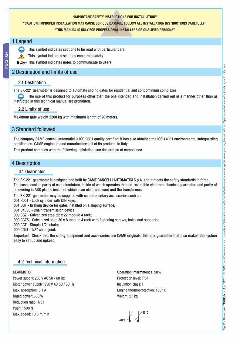
4.1 Gearmotor
The BK-221 gearmotor is designed and built by CAME CANCELLI AUTOMATICI S.p.A. and it meets the safety standards in force. The case consists partly of cast aluminium, inside of which operates the non-reversible electromechanical gearmotor, and partly of a covering in ABS plastic inside of which is an electronic card and the transformer.The BK-221 gearmotor may be supplied with complementary accessories such as:001 R001 - Lock cylinder with DIN keys;001 BSF - Braking device for gates installed on a sloping surface;001 B4353 - Chain transmission device;009 CGZ - Galvanized steel 22 x 22 module 4 rack;009 CGZS - Galvanized steel 30 x 8 module 4 rack with fastening screws, holes and supports;009 CCT - Simple 1/2” chain;009 CGIU - 1/2” chain joint.Important! Check that the safety equipment and accessories are CAME originals; this is a guarantee that also makes the system easy to set up and upkeep.
4 Description
2.1 Destination
1 Legend This symbol indicates sections to be read with particular care.
This symbol indicates sections concernig safety
This symbol indicates notes to communicate to users.
The company CAME cancelli automatici is ISO 9001 quality certifi ed; it has also obtained the ISO 14001 environmental safeguarding certifi cation. CAME engineers and manufactures all of its products in Italy. This product complies with the following legislation: see declaration of compliance.
2 Destination and limits of use
The BK-221 gearmotor is designed to automate sliding gates for residential and condominium complexes. The use of this product for purposes other than the one intended and installation carried out in a manner other than as instructed in this technical manual are prohibited.
3 Standard followed
“IMPORTANT SAFETY INSTRUCTIONS FOR INSTALLATION”
“CAUTION: IMPROPER INSTALLATION MAY CAUSE SERIOUS DAMAGE, FOLLOW ALL INSTALLATION INSTRUCTIONS CAREFULLY”
“THIS MANUAL IS ONLY FOR PROFESSIONAL INSTALLERS OR QUALIFIED PERSONS”
2.2 Limits of use
Maximum gate weight 2200 kg with maximum length of 20 meters.
4.2 Technical information
GEARMOTORPower supply: 230 V AC 50 / 60 HzMotor power supply: 230 V AC 50 / 60 HzMax. absorption: 5.1 A Rated power: 580 W Reduction ratio: 1/31Push: 1500 NMax. speed: 10,5 m/min
Operation intermittence: 50%Protection level: IP54Insulation class: IEngine thermoprotection: 150° CWeight: 21 kg

CAME
360
105
15
22 m
ax.
182.5 142.5 170
255
106
7
1
3
2
4 5
6
3
76
1
5
4
8
9
10
2
Pag
. 3
-
Man
ual
cod
e : 1
19
BV
25
119
BV
25
ver
. 1
.21
.2 0
8/2
011
©
CA
ME
cance
lli a
utom
atic
i s.p
.a.
- Th
e dat
a an
d in
form
atio
n re
por
ted
in t
his
inst
alla
tion
man
ual
are
susc
eptib
le t
o ch
ange
at a
ny t
ime
and
with
out
oblig
atio
n on
CA
ME
cance
lli a
utom
atic
i s.p
.a.
to n
otify
use
rs.
EN
GLIS
H
4.4 Overall dimensions
Measurements in mm
4.3 Parts description
GEARMOTOR UNIT
Gearmotor1. Board cover support2. End-stop fl aps3. ZBK10 basic control board4. Electric board front cover5. Release door6. Base plate7. Securing screws8. Plates for securing screws9. Nuts 10.
ACCESSORIES
R001 - Cylinder lock with DIN keys1. BSF - Braking device2. B4353 - Chain transmission device3. CCT - Simple 1/2” chain4. CGIU - 1/2” chain joint5. CGZ - Galvanized steel 22 x 22 module 4 rack6. CGZS - Galvanized steel 30 x 8 module 4 rack with fastening 7. screws, holes and supports

Pag
. 4
-
Man
ual
cod
e: 1
19
BV
25
119
BV
25
ver
. 1
.21
.2 0
8/2
011
©
CA
ME
cance
lli a
utom
atic
i s.p
.a.
- Th
e dat
a an
d in
form
atio
n re
por
ted
in t
his
inst
alla
tion
man
ual
are
susc
eptib
le t
o ch
ange
at a
ny t
ime
and
with
out
oblig
atio
n on
CA
ME
cance
lli a
utom
atic
i s.p
.a.
to n
otify
use
rs.
EN
GLIS
H
5.1 Preliminary checks
Before actually installing the gate operator, your are required to:• Check that the leaf is rigid and compact and that the rollers are in good working order and properly greased;• The gate track must be firmly set into the ground, above ground along its entire length and free of any foreign objects (debris) that may hamper the gate’s movement;• The top non-pinch rollers must not cause any friction;• See to installing physical stops at fully-opened and fully-closed positions and the power supply line trench as per the standard installation;• Make sure that the spot were the operator is mounted is located in an area that is protects it from any impacts, and that the mounting surface be solid; • See to installing a suitable all-pole disconnector switch, with power isolation contacts more than 3mm apart from each other;• Connections inside of the casing made to provide continuity to the protection circuit are allowed, as long as they have additional isolation compared to other internal conductive parts; • Set up suitable tubing and trenching to allow for electrical cables to pass, making sure they are free from any potential mechanical damage.
Only expert, qualified personnel must carry out the installation, in full compliance with the applicable law.
5 Installation
5.2 Tools and materials
Make sure you have all the tools and materials handy, to carry out the installation in total safety, according to the laws in-force. Below is a drawing of the tools you will need to install the operator.
N.B.: An evaluation of the size of the cables with lengths other than the data in the table must be made based on the eff ective absorption of the connected devices, according to the instructions indicated by the CEI EN 60204-1 standards.For connections that require several loads on the same line (sequential), the size given on the table must be re-evaluated based on actual absorption and distances.
5.3 Cable list and minimun thickness
Connections Type of cableLength of cable
1 < 10 m
Length of cable
10 < 20 m
Length of cable
20 < 30 m
120V-230V 2F power supply
FROR CEI 20-22 CEI EN
50267-2-1
3G x 1,5 mm2 3G x 2,5 mm2 3G x 4 mm2
230V flashing lamp 2 x 0,5 mm2 2 x 1 mm2 2 x 1,5 mm2
Photoelectric cells TX 2 x 0,5 mm2 2 x 0.5 mm2 2 x 0,5 mm2
Photoelectric cells RX 4 x 0,5 mm2 4 x 0,5 mm2 4 x 0,5 mm2
24V power supply accessory 2 x 0,5 mm2 2 x 0,5 mm2 2 x 1 mm2
Control button 2 x 0,5 mm2 2 x 0,5 mm2 2 x 0,5 mm2
Antenna connection RG58 max. 50 m
6
5
9
3
1
2
4
9
10
10
11
7
6
5
9
3
1
2
4 12
11
1010
8
4
CAME
Pag
. 5
-
Man
ual
cod
e : 1
19
BV
25
119
BV
25
ver
. 1
.21
.2 0
8/2
011
©
CA
ME
cance
lli a
utom
atic
i s.p
.a.
- Th
e dat
a an
d in
form
atio
n re
por
ted
in t
his
inst
alla
tion
man
ual
are
susc
eptib
le t
o ch
ange
at a
ny t
ime
and
with
out
oblig
atio
n on
CA
ME
cance
lli a
utom
atic
i s.p
.a.
to n
otify
use
rs.
EN
GLIS
H
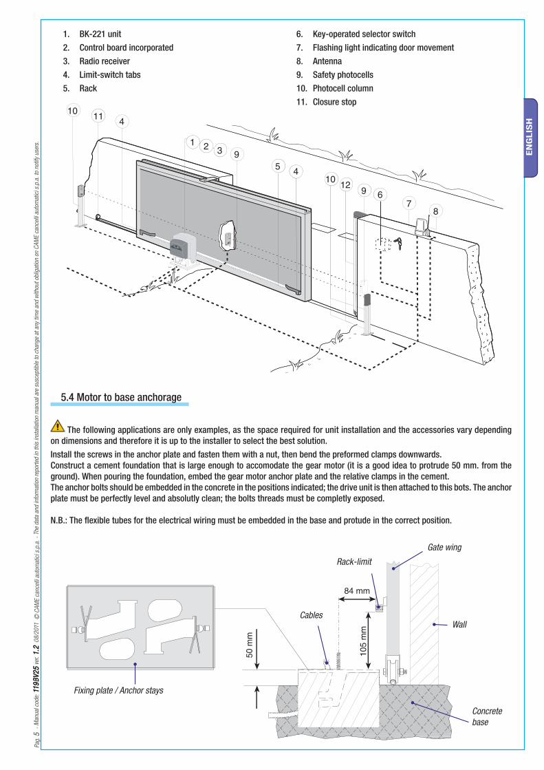
BK-221 unit 1. Control board incorporated2. Radio receiver3. Limit-switch tabs4. Rack5.
Key-operated selector switch6. Flashing light indicating door movement7. Antenna8. Safety photocells9. Photocell column10. Closure stop11.
The following applications are only examples, as the space required for unit installation and the accessories vary depending on dimensions and therefore it is up to the installer to select the best solution.Install the screws in the anchor plate and fasten them with a nut, then bend the preformed clamps downwards. Construct a cement foundation that is large enough to accomodate the gear motor (it is a good idea to protrude 50 mm. from the ground). When pouring the foundation, embed the gear motor anchor plate and the relative clamps in the cement.The anchor bolts should be embedded in the concrete in the positions indicated; the drive unit is then attached to this bots. The anchor plate must be perfectly level and absolutly clean; the bolts threads must be completly exposed.
N.B.: The fl exible tubes for the electrical wiring must be embedded in the base and protude in the correct position.
5.4 Motor to base anchorage
Fixing plate / Anchor stays
Cables
Concrete base
Rack-limit Gate wing
Wall

5÷10
mm
.
Pag
. 6
-
Man
ual
cod
e: 1
19
BV
25
119
BV
25
ver
. 1
.21
.2 0
8/2
011
©
CA
ME
cance
lli a
utom
atic
i s.p
.a.
- Th
e dat
a an
d in
form
atio
n re
por
ted
in t
his
inst
alla
tion
man
ual
are
susc
eptib
le t
o ch
ange
at a
ny t
ime
and
with
out
oblig
atio
n on
CA
ME
cance
lli a
utom
atic
i s.p
.a.
to n
otify
use
rs.
EN
GLIS
H
Horizontal adjustment and unit anchorage
Vertical adjustment and unit leveling
Cable entrances
Afstand tussen tandwiel en tandlatModule M6 = 1,5 mm speling
During the initial phase of installation, the feet should protrude by 5-10 mm. in order to allow for alignment, anchorage of the rack and further adjustments.Perfect alignment with the guide rail is made possible by the (paten-ted) built-in regulation system, which consists of: - slots for horizontal adjustment;- threaded steel feet for vertical adjustment and levelling;- plates and bolts for anchorage to the base.
5.5 Unit installation
5.6 Attaching the rack/limit
Attach the rack to the gate as described below:- Release the gearmotor (parag. 5.8);- position the rack on the pinion of the gearmotor and slide the gate manually in order to attach the rack along its entire length;- when the rack is attached to the gate, adjust the feet using a screwdriver until the play between the pinion and the rack is correct
(1÷2 mm.).N.B.: This position ensures that the weight of the gate does not rest on the gearmotor.- If the rack is already attached, proceed directly to the adju-stment of the rack/pinion coupling. - when the necessary adjustment have been completed, fasten the unit in position by tightening the two anchor bolts.
Pag
. 7
-
Man
ual
cod
e : 1
19
BV
25
119
BV
25
ver
. 1
.21
.2 0
8/2
011
©
CA
ME
cance
lli a
utom
atic
i s.p
.a.
- Th
e dat
a an
d in
form
atio
n re
por
ted
in t
his
inst
alla
tion
man
ual
are
susc
eptib
le t
o ch
ange
at a
ny t
ime
and
with
out
oblig
atio
n on
CA
ME
cance
lli a
utom
atic
i s.p
.a.
to n
otify
use
rs.
EN
GLIS
H
BLOCK
RELEASE
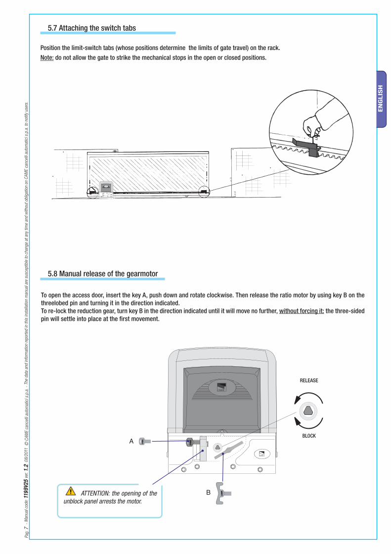
To open the access door, insert the key A, push down and rotate clockwise. Then release the ratio motor by using key B on the threelobed pin and turning it in the direction indicated. To re-lock the reduction gear, turn key B in the direction indicated until it will move no further, without forcing it: the three-sid ed pin will settle into place at the fi rst movement.
5.7 Attaching the switch tabs
Position the limit-switch tabs (whose positions determine the limits of gate travel) on the rack.Note: do not allow the gate to strike the mechanical stops in the open or closed positions.
5.8 Manual release of the gearmotor
ATTENTION: the opening of the unblock panel arrests the motor.

L N L1T L2T CT VS VF U V W E EX 26V 17V 0 10 11TS 1 2 3 3P 4 5 7 2 CX CY C7 C8 2 A B + E D FC FA F
4
10
11
6
812 13
9 1
7
5 2 3
Pag
. 8
-
Man
ual
cod
e: 1
19
BV
25
119
BV
25
ver
. 1
.21
.2 0
8/2
011
©
CA
ME
cance
lli a
utom
atic
i s.p
.a.
- Th
e dat
a an
d in
form
atio
n re
por
ted
in t
his
inst
alla
tion
man
ual
are
susc
eptib
le t
o ch
ange
at a
ny t
ime
and
with
out
oblig
atio
n on
CA
ME
cance
lli a
utom
atic
i s.p
.a.
to n
otify
use
rs.
EN
GLIS
H
FUSE TABLE ZBK10To protect: fuse:
Control board (line) 8 A-F
Accessories 1.6 A-F
Command devices 1 A-F
TECHNICAL INFORMATIONPower supply 230 V - 50 / 60 Hz
Absorption at rest 110 mA
Maximum power for 24V accessories 37 W
6 Control board
6.1 General description
6.2 Main components
Use 230V A.C. to power the electronic card using the L-N terminals, at a max 50/60Hz frequency.Use 24V to power the command devices and accessories. Careful! The accessories cannot exceed 37W of overall power.All connections are protected by quick-fuses – see table.The input and output contact functions, the timing settings and users’ management, are set and viewed on the display, which is run by software.
Warning! Before acting on the machinery, cut off the main power supply and disconnect any emergency batteries.
Display1. Card fuse2. Accessory fuse3. Line fuse4. AF card coupling for remote control5. RSE card coupling for paired connections6.
230 V-power signalling LED7. Connecting terminal board8. Programming buttons9. Display lighting adjustment trimmer10. Memory roll board connector11. Power supply terminals12. Antenna terminals13.

COM
COM
NC
NC
NC
NC
COM
COM
Pag
. 9
-
Man
ual
cod
e : 1
19
BV
25
119
BV
25
ver
. 1
.21
.2 0
8/2
011
©
CA
ME
cance
lli a
utom
atic
i s.p
.a.
- Th
e dat
a an
d in
form
atio
n re
por
ted
in t
his
inst
alla
tion
man
ual
are
susc
eptib
le t
o ch
ange
at a
ny t
ime
and
with
out
oblig
atio
n on
CA
ME
cance
lli a
utom
atic
i s.p
.a.
to n
otify
use
rs.
EN
GLIS
H
6.3 Electrical connections
230V (A.C.) motor with encoder
Closing microswitch
Gearmotor, endstop and encoder
Modifications to the electrical connections for right-hand installations
Invert the gearmotor (U-V) and (FA-FC) endstop phases.
Opening microswitch
Description of the standard electrical connections for left-hand installations
BlackRed
Terminals for powering the following accessories: - 24V A.C. Maximum allowed power: 37W
Power supply for accessories
230V (A.C.) Power, 50/60Hz frequency
Cable lug with bolt and washer for connecting to earth.
Orange
Orange
White
Red
White
Red
Capacitor
Capacitor

Pag
. 1
01
0
- M
anual
cod
e: 1
19
BV
25
119
BV
25
ver
. 1
.21
.2 0
8/2
011
©
CA
ME
cance
lli a
utom
atic
i s.p
.a.
- Th
e dat
a an
d in
form
atio
n re
por
ted
in t
his
inst
alla
tion
man
ual
are
susc
eptib
le t
o ch
ange
at a
ny t
ime
and
with
out
oblig
atio
n on
CA
ME
cance
lli a
utom
atic
i s.p
.a.
to n
otify
use
rs.
EN
GLIS
H
Open-gate status light (contact range: 24V – 3W max)
- Signal that gate is open; turns off when gate is closed.
Movement fl ashing light (Contact range: 230V – 25W max).- Flashes during the gate’s opening and closing phases.
Command and control devices
Warning devices
Cycle lamp (contact rating: 230V – 60W max.).- It lights up the driving area and stays on from the moment the gate begins to open until it is fully closed (including the automatic closing time). If automatic closing is not activated, the lamp stays on only during movement or for a set time of 5 minutes if used as a courtesy lamp.
Courtesy lamp (Contact output: 230 V - 60 W max.) - Auxiliary connection for suitably positioned external lamp to increase lighting of the steering area. It remain lit for a fi xed time of 5 minutes.
Stop button (N.C. contact) - Gate stop button. Excludes automatic closing. For motion to resume, press the command button or the remote control button.N.B.: if contact is unused, select OFF on the “FUNCTIONS” menu.
Key selector and/or opening button (N.O. contact) - Gate opening command.
Key selector and/or commands button (N.O.
contact) Commands for opening and closing the gate – pressing the button or turning the key-switch, inverts the gate’s movement or stops it depending on how it is set on the 2-7 command in the “FUNCTIONS” menu
Key selector and/or partial opening button (N.O.
contact) - Partial gate opening for pedestrian access.
Key selector and/or closing button (N.O. contact) - Gate closing command.
Antenna with RG58 cable for the remote
control.
or in alternative
or in alternative
RX TX
RX TX
Pag
. 1111
-
Man
ual
cod
e : 1
19
BV
25
119
BV
25
ver
. 1
.21
.2 0
8/2
011
©
CA
ME
cance
lli a
utom
atic
i s.p
.a.
- Th
e dat
a an
d in
form
atio
n re
por
ted
in t
his
inst
alla
tion
man
ual
are
susc
eptib
le t
o ch
ange
at a
ny t
ime
and
with
out
oblig
atio
n on
CA
ME
cance
lli a
utom
atic
i s.p
.a.
to n
otify
use
rs.
EN
GLIS
H
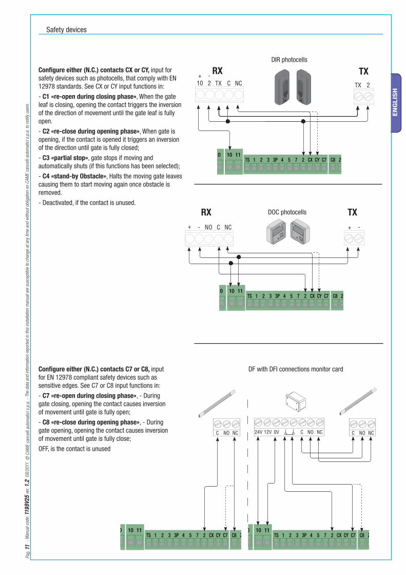
Safety devices
Confi gure either (N.C.) contacts CX or CY, input for safety devices such as photocells, that comply with EN 12978 standards. See CX or CY input functions in:- C1 «re-open during closing phase», When the gate leaf is closing, opening the contact triggers the inversion of the direction of movement until the gate leaf is fully open.- C2 «re-close during opening phase», When gate is opening, if the contact is opened it triggers an inversion of the direction until gate is fully closed;- C3 «partial stop», gate stops if moving and automatically shuts (if this functions has been selected);- C4 «stand-by Obstacle», Halts the moving gate leaves causing them to start moving again once obstacle is removed. - Deactivated, if the contact is unused.
DIR photocells
DOC photocells
Confi gure either (N.C.) contacts C7 or C8, input for EN 12978 compliant safety devices such as sensitive edges. See C7 or C8 input functions in:- C7 «re-open during closing phase», - During gate closing, opening the contact causes inversion of movement until gate is fully open;- C8 «re-close during opening phase», - During gate opening, opening the contact causes inversion of movement until gate is fully close;OFF, is the contact is unused
DF with DFI connections monitor card

(DOC) (DIR)
0 17
24
FR
EN
O
1 2 3 4
SP
UN
TO
L N L1T L2T CT VS VF U V W E EX 26V 17V 0 10 11TS
Pag
. 1
21
2
- M
anual
cod
e: 1
19
BV
25
119
BV
25
ver
. 1
.21
.2 0
8/2
011
©
CA
ME
cance
lli a
utom
atic
i s.p
.a.
- Th
e dat
a an
d in
form
atio
n re
por
ted
in t
his
inst
alla
tion
man
ual
are
susc
eptib
le t
o ch
ange
at a
ny t
ime
and
with
out
oblig
atio
n on
CA
ME
cance
lli a
utom
atic
i s.p
.a.
to n
otify
use
rs.
EN
GLIS
H
6.4 Electrical connection to operate the photocells’ safety test
At each open/close command, the card check the photocells’ effi ciency. Any problems with the photocells will cause the (PROG) Led to fl ash on the electronic card, which cancels any commands from the radio transmitter or push-button.
Electrical connection to operate the photocells’ safety test:
- The transmitter and receiver, must be connected as shown in the diagram;- from the functions menu, select “safety tests” and select either CX or CY input/s to activate the test.
6.5 Motor torque limiter
To vary the motor torque, move the shown faston (the one with the black wire) to one of the 4 positions: 1 min – 4 max.

WWW.CAME.IT
ZBK10
LANGUAGE
English
LANGUAGE
EnglishFUNCTIONS
EnglishTIMING ADJ.
A.C.T.
90sCycle Time
90s
Cycle Time
90s
Cycle Time
100s
LANGUAGE
Pag
. 1
31
3
- M
anual
cod
e : 1
19
BV
25
119
BV
25
ver
. 1
.21
.2 0
8/2
011
©
CA
ME
cance
lli a
utom
atic
i s.p
.a.
- Th
e dat
a an
d in
form
atio
n re
por
ted
in t
his
inst
alla
tion
man
ual
are
susc
eptib
le t
o ch
ange
at a
ny t
ime
and
with
out
oblig
atio
n on
CA
ME
cance
lli a
utom
atic
i s.p
.a.
to n
otify
use
rs.
EN
GLIS
H
N.B.: when the menu is active, the system cannot be used.
The ENTER key is for:- entering the menu
- confirming and memorising set values
The ESC key is for:- exiting the menu
- cancelling modifications
The <> keys are for:- shifting from one menu item to another
- increase or decrease values
the <...> symbols on the display are for:- pointing out the currently, selected item
To enter the menu, keep the ENTER key pressed for at least one second.
To select a menu item, mode using the greater than-lesser than keys...
...then press ENTER
also use the greater than-lesser than keys for the “sub-menus”...
If the <> are on the TIME function, you may modify the value.
To increase or reduce values, use the greater than-lesser than keys...
...then press ENTER to confirm...
...to exit the menu, wait 30 seconds, or press ESC, until start screen is displayed.
7 Programming
LANGUAGE
English
LANGUAGE
EnglishFUNCTIONS
EnglishTIMING ADJ.
A.C.T.
90sCycle Time
90s
Cycle Time
90s
Cycle Time
100s
LANGUAGE
7.1 Description of display commands
7.2 Browsing the menu

ENTER
>ENTER
>
>ENTER >
>
ENTER
>>
>ENTER
>
>ENTER
>
>ENTER
>
ENTER
>ENTER
ENTER
ENTER
ENTER
ENTER
>ENTER
ENTER
ENTER > >
>
>
>
>
>
>
>
>
>
>
>
ENTER>
>
>
>
>
>
>
>ENTER
>
>
>ENTER
>
>
ENTER
>
>
ENTER
ENTER >
>
ENTER>
>
ENTER>
>
>
>
>
>
>
>
>
>
>
>
>
>
>
< LANGUAGE >
<TIMING ADJ.>
<ADJUSTMENTS>
<English>
< INFO >
<Francais> <Deutsch>
<Espanol><Italiano>
< A.C.T. >
< Cycle Time >
<Preflashing T.>
<Partial A.C.T.>
< New User >
< Modify User >
< Remove Usr. >
< Backup data >
<Restore backup>
<Delete all Usr>
<Gate run Adj >
< Slowdown >
<Gate run sens.>
<Slowdown sens.>
< Partial op. >
< Encoder >
< NET address >
< Startup Msg >
< 10s >
< FUNCTIONS >
< 11s >
< 90s >
< 91s >
< 5s >
< 6s >
< 5s >
< 6s >
<2-7 Func>
<Only Open>
< RADIO USRS >
Do you conf.?< No >
< FW Version >
ver. 1.0
<Manoeuvres No.>
16480
<Partial>
Reading
ooooooo•••
Writing
ooooooo•••
n.001 In use
n.002 Empty
n.001 In use
n.002 Empty
< 10% >
< 11% >
< 10% >
< 11% >
< Disabled >
< Master >
< Slave >
WWW.CAME.IT
ZBK10
< ON >
< OFF >
<-oooooooo+>•
<-oooooooo+>•
< -oooo+ >•
< -oooo+ >•
Do you conf.?< Yes >
Pag
. 14
14
-
Man
ual
cod
e: 1
19
BV
25
119
BV
25
ver
. 1
.21
.2 0
8/2
011
©
CA
ME
cance
lli a
utom
atic
i s.p
.a.
- Th
e dat
a an
d in
form
atio
n re
por
ted
in t
his
inst
alla
tion
man
ual
are
susc
eptib
le t
o ch
ange
at a
ny t
ime
and
with
out
oblig
atio
n on
CA
ME
cance
lli a
utom
atic
i s.p
.a.
to n
otify
use
rs.
EN
GLIS
H
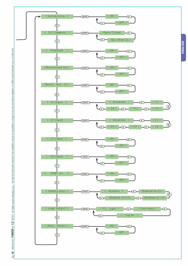
7.3 Menu structure
< LANGUAGE >
<TIMING ADJ.>
<ADJUSTMENTS>
<English>
< INFO >
<Francais> <Deutsch>
<Espanol><Italiano>
< A.C.T. >
< Cycle Time >
<Preflashing T.>
<Partial A.C.T.>
< New User >
< Modify User >
< Remove Usr. >
< Backup data >
<Restore backup>
<Delete all Usr>
<Gate run Adj >
< Slowdown >
<Gate run sens.>
<Slowdown sens.>
< Partial op. >
< Encoder >
< NET address >
< Startup Msg >
< 10s >
< FUNCTIONS >
< 11s >
< 90s >
< 91s >
< 5s >
< 6s >
< 5s >
< 6s >
<2-7 Func>
<Only Open>
< RADIO USRS >
Do you conf.?< No >
< FW Version >
ver. 1.0
<Manoeuvres No.>
16480
<Partial>
Reading
ooooooo•••
Writing
ooooooo•••
n.001 In use
n.002 Empty
n.001 In use
n.002 Empty
See detailed description on chap. 7.14
< 10% >
< 11% >
< 10% >
< 11% >
< Disabled >
< Master >
< Slave >
WWW.CAME.IT
ZBK10
< ON >
< OFF >
<-oooooooo+>•
<-oooooooo+>•
< -oooo+ >•
< -oooo+ >•
Do you conf.?< Yes >
ENTER
ENTER
ENTER
ENTER
ENTER
ENTER
ENTER
ENTER
ENTER
ENTER
ENTER
ENTER
ENTER
>
>
>
>
>
>>
>>
>
>
>
>
>
>
>
>
>>
>>
>
>
>
>
>
>
>
>
>
>
>
>
>
>
>
>
>
>
>
>
>
>
>
>
>
>
< ON >
< OFF >
<Op.-Stop-Cl.>
<Open Close>
< Disabled > < C1 >
< C2 >< C3 >< C4 >
< Disable > <Enabled on CX>
<Enabled on CY><Enabled CX+CY>
< Autom.Clos. >
< 2-7 Command >
< Preflash >
<Maintained Act>
<Maint. Act. Cl.>
< CY Input >
< C7 Input >
< C8 Input >
< STOP (1) >
< Safety test >
< Lamp Output >
< CX Input >
< ON >
< OFF >
< ON >
< OFF >
< ON >
< OFF >
< Disabled > < C1 >
< C2 >< C3 >< C4 >
< ON >
< OFF >
< ON >
< OFF >
< ON >
< OFF >
< Cycle >
< Courtesy >< Fl. light >
< Obst. Detect > < ON >
< OFF >
Pag
. 1
51
5
- M
anual
cod
e : 1
19
BV
25
119
BV
25
ver
. 1
.21
.2 0
8/2
011
©
CA
ME
cance
lli a
utom
atic
i s.p
.a.
- Th
e dat
a an
d in
form
atio
n re
por
ted
in t
his
inst
alla
tion
man
ual
are
susc
eptib
le t
o ch
ange
at a
ny t
ime
and
with
out
oblig
atio
n on
CA
ME
cance
lli a
utom
atic
i s.p
.a.
to n
otify
use
rs.
EN
GLIS
H
< ON >
< OFF >
<Op.-Stop-Cl.>
<Open Close>
< Disabled > < C1 >
< C2 >< C3 >< C4 >
< Disable > <Enabled on CX>
<Enabled on CY><Enabled CX+CY>
< Autom.Clos. >
< 2-7 Command >
< Preflash >
<Maintained Act>
<Maint. Act. Cl.>
< CY Input >
< C7 Input >
< C8 Input >
< STOP (1) >
< Safety test >
< Lamp Output >
< CX Input >
< ON >
< OFF >
< ON >
< OFF >
< ON >
< OFF >
< Disabled > < C1 >
< C2 >< C3 >< C4 >
< ON >
< OFF >
< ON >
< OFF >
< ON >
< OFF >
< Cycle >
< Courtesy >< Fl. light >
< Obst. Detect > < ON >
< OFF >
>

X 2
X 2
LANGUAGE
EnglishFUNCTIONS TIMING ADJ.
RADIO USRSADJUSTMENTSINFO
< LANGUAGE >
English
LANGUAGE
< English >LANGUAGE
< Francais >
LANGUAGE
< Deutsch >
LANGUAGE
< Espanol >
LANGUAGE
< Italiano >
< Autom.Clos. >
ON
Autom.Clos.
< ON >
Autom.Clos.
< OFF >
< 2-7 Command >
Op.-Stop-Cl.
2-7 Command
< Op.-Stop-Cl. >
2-7 Command
< Open Close >
FUNCTIONS
FUNCTIONS
Pag
. 1
61
6
- M
anual
cod
e: 1
19
BV
25
119
BV
25
ver
. 1
.21
.2 0
8/2
011
©
CA
ME
cance
lli a
utom
atic
i s.p
.a.
- Th
e dat
a an
d in
form
atio
n re
por
ted
in t
his
inst
alla
tion
man
ual
are
susc
eptib
le t
o ch
ange
at a
ny t
ime
and
with
out
oblig
atio
n on
CA
ME
cance
lli a
utom
atic
i s.p
.a.
to n
otify
use
rs.
EN
GLIS
H
7.4 Main menu
LANGUAGE
EnglishFUNCTIONS TIMING ADJ.
RADIO USRSADJUSTMENTSINFO
Press ENTER for 1 second
7.5 Language menu
Select language: selects among the languages displayed.
< LANGUAGE >
English
LANGUAGE
< English >LANGUAGE
< Francais >
LANGUAGE
< Deutsch >
LANGUAGE
< Espanol >
LANGUAGE
< Italiano >
FUNCTIONSFUNCTIONSFUNCTIONSFUNCTIONS
TIMING ADJ.TIMING ADJ.IMING ADJIMING ADJ
RADIO USRSRADIO USRSADIO USRSADIO USRS
ADJUSTMENTSADJUSTMENTSDJUSTMENTDJUSTMENT
7.6 Functions menu
< Autom.Clos. >
ON
Autom.Clos.
< ON >
Autom.Clos.
< OFF >
Automatic Closing: activates or deactivates the automatic closing function.The automatic closing timer activates at each opening endpoint. The predetermined time may be adjusted, and is in any case dependent on any safety devices that may activate; and it does not activate after a total safety “stop” or during a power outage.
2-7 Command: sets the sequential command.“Open-close” or “open-stop-close-stop” function with button [2-7] and radio transmitter (when radio-frequency card is inserted)
< 2-7 Command >
Op.-Stop-Cl.
2-7 Command
< Op.-Stop-Cl. >
2-7 Command
< Open Close >
INFOINFOINFOINFO
< LANGUAGE >< LANGUAGE >
EnglishEnglishhh
FUNCTIONS
TIMING ADJ.TIMING ADJ.IMING ADJIMING ADJ
RADIO USRSRADIO USRSRADIO USRRADIO USR
ADJUSTMENTSADJUSTMENTSDJUSTMENDJUSTMEN
INFOINFOINFOINFO
< LANGUAGE >< LANGUAGE >
EnglishEnglishhh
FUNCTIONS
TIMING ADJ.TIMING ADJ.TIMING ADTIMING AD
RADIO USRSRADIO USRSRADIO USRRADIO USR
ADJUSTMENTSADJUSTMENTSDJUSTMENDJUSTMEN
INFOINFOINFOINFO
X 2
X 2
X 2
X 2
X 3
X 2
X 4
X 5
< Preflash >
OFF
Preflash
< OFF >
Preflash
< ON >
< CX Input >
Disabled
CX Input
< Disabled >
CX Input
< C1 >
CX Input
< C2 >
CX Input
< C3 >
CX Input
< C4 >
Maintained Act
< OFF >
<Maintained Act>
OFF
Maintained Act
< ON >
Maint.Act. Cl.
< OFF >< Maint.Act. Cl. >
OFF
Maint.Act. Cl.
< ON >
FUNCTIONS
FUNCTIONS
FUNCTIONS
FUNCTIONS
Pag
. 1717
-
Man
ual
cod
e : 1
19
BV
25
119
BV
25
ver
. 1
.21
.2 0
8/2
011
©
CA
ME
cance
lli a
utom
atic
i s.p
.a.
- Th
e dat
a an
d in
form
atio
n re
por
ted
in t
his
inst
alla
tion
man
ual
are
susc
eptib
le t
o ch
ange
at a
ny t
ime
and
with
out
oblig
atio
n on
CA
ME
cance
lli a
utom
atic
i s.p
.a.
to n
otify
use
rs.
EN
GLIS
H
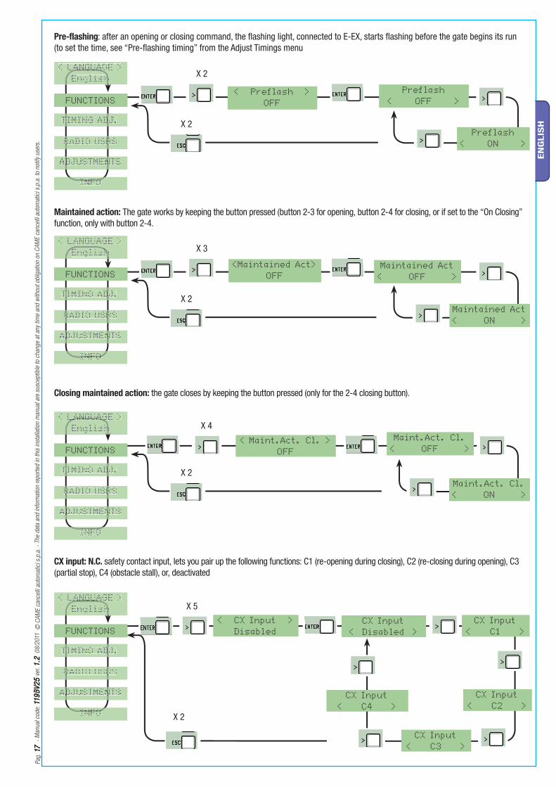
Pre-flashing: after an opening or closing command, the fl ashing light, connected to E-EX, starts fl ashing before the gate begins its run (to set the time, see “Pre-fl ashing timing” from the Adjust Timings menu
< Preflash >
OFF
Preflash
< OFF >
Preflash
< ON >
Maintained action: The gate works by keeping the button pressed (button 2-3 for opening, button 2-4 for closing, or if set to the “On Closing” function, only with button 2-4.
Closing maintained action: the gate closes by keeping the button pressed (only for the 2-4 closing button).
CX input: N.C. safety contact input, lets you pair up the following functions: C1 (re-opening during closing), C2 (re-closing during opening), C3 (partial stop), C4 (obstacle stall), or, deactivated
< CX Input >
Disabled
CX Input
< Disabled >
CX Input
< C1 >
CX Input
< C2 >
CX Input
< C3 >
CX Input
< C4 >
Maintained Act
< OFF >
<Maintained Act>
OFF
Maintained Act
< ON >
Maint.Act. Cl.
< OFF >< Maint.Act. Cl. >
OFF
Maint.Act. Cl.
< ON >
< LANGUAGE >< LANGUAGE >LANGUAANGUA
EnglishEnglishhh
FUNCTIONS
TIMING ADJ.TIMING ADJ.TIMING ADTIMING AD
RADIO USRSRADIO USRSRADIO USRRADIO USR
ADJUSTMENTSADJUSTMENTSDJUSTMENDJUSTMEN
INFOINFOINFOINFO
< LANGUAGE >< LANGUAGE >
EnglishEnglishEnglishh
FUNCTIONS
TIMING ADJ.TIMING ADJ.TIMING ADTIMING AD
RADIO USRSRADIO USRSRADIO USRRADIO USR
ADJUSTMENTSADJUSTMENTSDJUSTMENDJUSTMEN
INFOINFOINFOINFO
< LANGUAGE >< LANGUAGE >LANGUAGLANGUAG
EnglishEnglishhh
FUNCTIONS
TIMING ADJ.TIMING ADJ.TIMING ADTIMING AD
RADIO USRSRADIO USRSRADIO USRRADIO USR
ADJUSTMENTSADJUSTMENTSDJUSTMENDJUSTMEN
INFOINFOINFOINFO
< LANGUAGE >< LANGUAGE >ANGUAANGUA
EnglishEnglishhh
FUNCTIONS
TIMING ADJ.TIMING ADJ.TIMING ADTIMING AD
RADIO USRSRADIO USRSRADIO USRRADIO USR
ADJUSTMENTSADJUSTMENTSDJUSTMENDJUSTMEN
INFOINFOINFOINFO

X 2
X 8
X 2
X 6
X 2
X 7
X 2
X 9
C8 Input
< OFF >
< C8 Input >
OFF
C8 Input
< ON >
< CY Input >
Disabled
CY Input
< Disabled >
CY Input
< C1 >
CY Input
< C2 >
CY Input
< C3 >
CY Input
< C4 >
C7 Input
< OFF >
< C7 Input >
OFF
C7 Input
< ON >
STOP (1)
< ON >
< STOP (1) >
OFF
STOP (1)
< OFF >
FUNCTIONS
FUNCTIONS
FUNCTIONS
FUNCTIONS
Pag
. 1
81
8
- M
anual
cod
e: 1
19
BV
25
119
BV
25
ver
. 1
.21
.2 0
8/2
011
©
CA
ME
cance
lli a
utom
atic
i s.p
.a.
- Th
e dat
a an
d in
form
atio
n re
por
ted
in t
his
inst
alla
tion
man
ual
are
susc
eptib
le t
o ch
ange
at a
ny t
ime
and
with
out
oblig
atio
n on
CA
ME
cance
lli a
utom
atic
i s.p
.a.
to n
otify
use
rs.
EN
GLIS
H
CY input: N.C. safety contact input, lets you pair up the following functions: C1 (re-opening during closing), C2 (re-closing during opening), C3 (partial stop), C4 (obstacle stall), or, deactivated
C7 input: N.C. safety contact input (re-opening when closing). This input is for EN 12978-compliant safety devices, like sensitive edges. When the gate is closing, the open contact triggers an inversion in the gate’s movement until it is fully opened.
C8 input: N.C. safety contact input (re-closing during opening). This input is for EN 12978-compliant safety devices, like sensitive edges. When the gate is opening, the open contact triggers an inversion in the gate’s movement until it is fully closed.
C8 Input
< OFF >
< C8 Input >
OFF
C8 Input
< ON >
< CY Input >
Disabled
CY Input
< Disabled >
CY Input
< C1 >
CY Input
< C2 >
CY Input
< C3 >
CY Input
< C4 >
C7 Input
< OFF >
< C7 Input >
OFF
C7 Input
< ON >
STOP (1)
< ON >
< STOP (1) >
OFF
STOP (1)
< OFF >
< LANGUAGE >< LANGUAGE >
EnglishEnglishhh
FUNCTIONS
TIMING ADJ.TIMING ADJ.TIMING ADTIMING AD
RADIO USRSRADIO USRSRADIO USRRADIO USR
ADJUSTMENTSADJUSTMENTSDJUSTMENDJUSTMEN
INFOINFOINFOINFO
< LANGUAGE >< LANGUAGE >ANGUAANGUA
EnglishEnglishhh
FUNCTIONS
TIMING ADJ.TIMING ADJ.TIMING ADTIMING AD
RADIO USRSRADIO USRSRADIO USRRADIO USR
ADJUSTMENTSADJUSTMENTSDJUSTMENDJUSTMEN
INFOINFOINFOINFO
< LANGUAGE >< LANGUAGE >
EnglishEnglishhh
FUNCTIONS
TIMING ADJ.TIMING ADJ.TIMING ADTIMING AD
RADIO USRSRADIO USRSRADIO USRRADIO USR
ADJUSTMENTSADJUSTMENTSDJUSTMENDJUSTMEN
INFOINFOINFOINFO
< LANGUAGE >< LANGUAGE >
EnglishEnglishEnglishEnglish
FUNCTIONS
TIMING ADJ.TIMING ADJ.TIMING ADTIMING AD
RADIO USRSRADIO USRSRADIO USRRADIO USR
ADJUSTMENTSADJUSTMENTSDJUSTMENDJUSTMEN
INFOINFOINFOINFO
STOP (1): this function stops the gate and consequently excludes any automatic closing cycle; for movement to resume, you need to use the keypad or transmitter. Insert safety device on [1-2]; is unused, select “OFF” and confirm with ENTER.

X 2
X 12
X 2
X10
X 2
X 11
Obst. Detect
< OFF >
< Obst. Detect >
OFF
Obst. Detect
< ON >
< Safety Test >
Disable
< Lamp Output >
Courtesy
Safety Test
<Enabled on CX>
Safety Test
<Enabled on CY>
Safety Test
< En.on CX + CY >
Lamp Output
< Courtesy >
Lamp Output
< Fl. light >
Lamp Output
< Cycle >
Safety Test
< Disable >FUNCTIONS
FUNCTIONS
FUNCTIONS
Pag
. 1
91
9
- M
anual
cod
e : 1
19
BV
25
119
BV
25
ver
. 1
.21
.2 0
8/2
011
©
CA
ME
cance
lli a
utom
atic
i s.p
.a.
- Th
e dat
a an
d in
form
atio
n re
por
ted
in t
his
inst
alla
tion
man
ual
are
susc
eptib
le t
o ch
ange
at a
ny t
ime
and
with
out
oblig
atio
n on
CA
ME
cance
lli a
utom
atic
i s.p
.a.
to n
otify
use
rs.
EN
GLIS
H
Safety test: Allows the card to check the efficiency of any safety devices (i.e. photocells) after every opening or closing command.
Lamp output: to configure the lamp connected to E-Ex:- cycle: outdoor lamp, which can be positioned at leisure, for better illumination in the parking/driveway area.It stays on from the moment the gate leaf begins to open, until it is fully closed (including automatic closing time).In case the automatic closing function is not inserted, it stays on only during gate movement.- courtesy: outdoor lamp, which can be positioned at leisure, for better illumination in the parking/driveway area.It stays on for a set time of 5 minutes.- flashing light: signals the gate opening or closing movement.
Obstacle detected - When motor is stopped (gate closed or after a total stop command) it prevents any movement if safety devices, such as photocells, detect any obstacles.
Obst. Detect
< OFF >
< Obst. Detect >
OFF
Obst. Detect
< ON >
< Safety Test >
Disable
< Lamp Output >
Courtesy
Safety Test
<Enabled on CX>
Safety Test
<Enabled on CY>
Safety Test
< En.on CX + CY >
Lamp Output
< Courtesy >
Lamp Output
< Fl. light >
Lamp Output
< Cycle >
Safety Test
< Disable >
< LANGUAGE >< LANGUAGE >ANGUAANGUA
EnglishEnglishhh
FUNCTIONS
TIMING ADJ.TIMING ADJ.TIMING ADTIMING AD
RADIO USRSRADIO USRSRADIO USRRADIO USR
ADJUSTMENTSADJUSTMENTSDJUSTMENDJUSTMEN
INFOINFOINFOINFO
< LANGUAGE >< LANGUAGE >ANGUAANGUA
EnglishEnglishhh
FUNCTIONS
TIMING ADJ.TIMING ADJ.TIMING ADTIMING AD
RADIO USRSRADIO USRSRADIO USRRADIO USR
ADJUSTMENTSADJUSTMENTSDJUSTMENDJUSTMEN
INFOINFOINFOINFO
< LANGUAGE >< LANGUAGE >
EnglishEnglishhh
FUNCTIONS
TIMING ADJ.TIMING ADJ.TIMING ADTIMING AD
RADIO USRSRADIO USRSRADIO USRRADIO USR
ADJUSTMENTSADJUSTMENTSDJUSTMENDJUSTMEN
INFOINFOINFOINFO
X 2
X 2
X 2
X 2
X 2
X 3
< A.C.T >
10 s
A.C.T.
< 10 s >
A.C.T.
< 11 s >
< Cycle Time >
90 s
Cycle Time
< 90 s >
< Preflashing T. >
5 s
Preflashing T.
< 5 s >
< Partial A.C.T. >
5 sPartial A.C.T.
< 5 s >
TIMING ADJ.
Cycle Time
< 91 s >
Preflashing T.
< 6 s >
Partial A.C.T.
< 6 s >
TIMING ADJ.
TIMING ADJ.
TIMING ADJ.
Pag
. 2
02
0
- M
anual
cod
e: 1
19
BV
25
119
BV
25
ver
. 1
.21
.2 0
8/2
011
©
CA
ME
cance
lli a
utom
atic
i s.p
.a.
- Th
e dat
a an
d in
form
atio
n re
por
ted
in t
his
inst
alla
tion
man
ual
are
susc
eptib
le t
o ch
ange
at a
ny t
ime
and
with
out
oblig
atio
n on
CA
ME
cance
lli a
utom
atic
i s.p
.a.
to n
otify
use
rs.
EN
GLIS
H
< A.C.T >
10 s
A.C.T.
< 10 s >
A.C.T.
< 11 s >
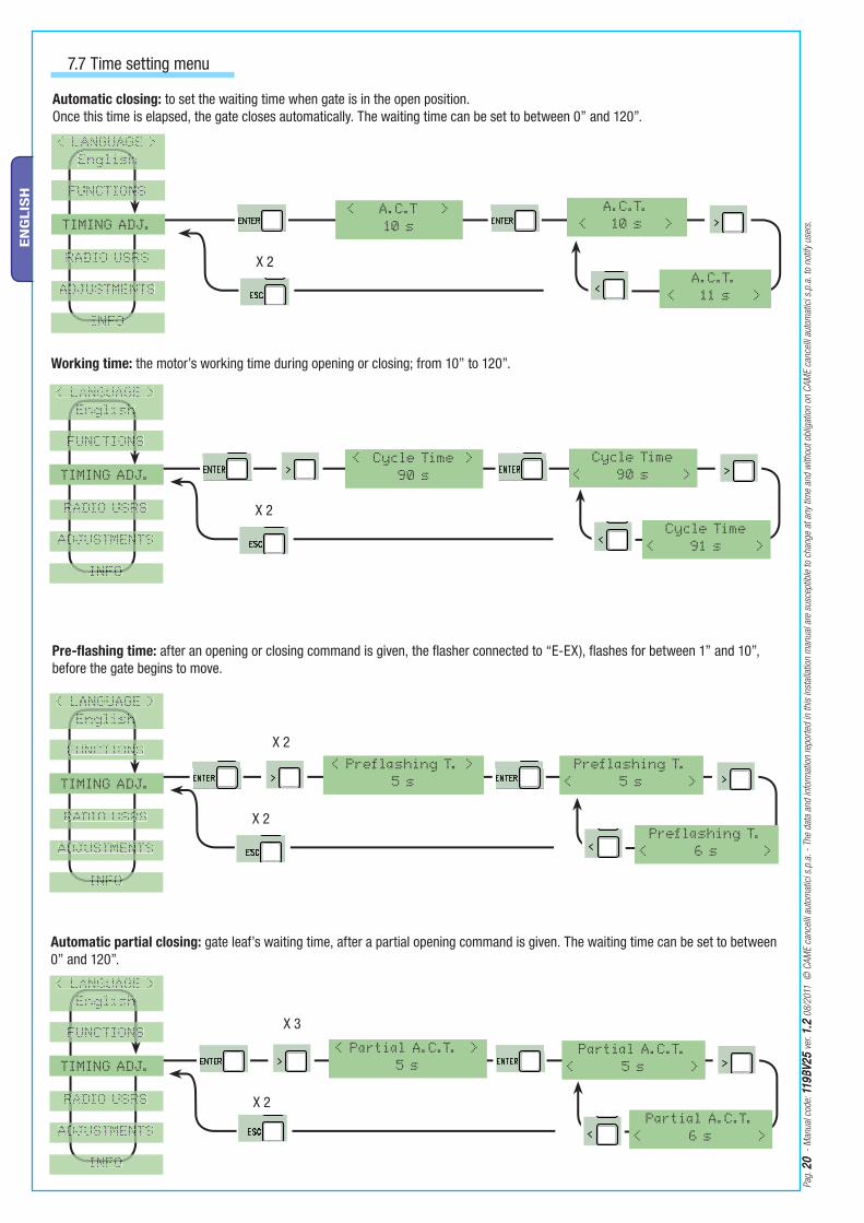
7.7 Time setting menu
Automatic closing: to set the waiting time when gate is in the open position.Once this time is elapsed, the gate closes automatically. The waiting time can be set to between 0” and 120”.
< Cycle Time >
90 s
Cycle Time
< 90 s >
Working time: the motor’s working time during opening or closing; from 10” to 120”.
< Preflashing T. >
5 s
Preflashing T.
< 5 s >
Pre-flashing time: after an opening or closing command is given, the flasher connected to “E-EX), flashes for between 1” and 10”, before the gate begins to move.
< Partial A.C.T. >
5 sPartial A.C.T.
< 5 s >
Automatic partial closing: gate leaf’s waiting time, after a partial opening command is given. The waiting time can be set to between 0” and 120”.
< LANGUAGE >< LANGUAGE >
EnglishEnglishhh
FUNCTIONSFUNCTIONSFUNCTIONFUNCTION
TIMING ADJ.
RADIO USRSRADIO USRSRADIO USRRADIO USR
ADJUSTMENTSADJUSTMENTSDJUSTMENDJUSTMEN
INFOINFOINFOINFO
Cycle Time
< 91 s >
Preflashing T.
< 6 s >
Partial A.C.T.
< 6 s >
< LANGUAGE >< LANGUAGE >
EnglishEnglishEnglishEnglish
FUNCTIONSFUNCTIONSFUNCTIONFUNCTION
TIMING ADJ.
RADIO USRSRADIO USRSRADIO USRRADIO USR
ADJUSTMENTSADJUSTMENTSDJUSTMENDJUSTMEN
INFOINFOINFOINFO
< LANGUAGE >< LANGUAGE >
EnglishEnglishEnglishEnglish
FUNCTIONSFUNCTIONSFUNCTIONFUNCTION
TIMING ADJ.
RADIO USRSRADIO USRSRADIO USRRADIO USR
ADJUSTMENTSADJUSTMENTSDJUSTMENDJUSTMEN
INFOINFOINFOINFO
< LANGUAGE >< LANGUAGE >
EnglishEnglishhh
FUNCTIONSFUNCTIONSFUNCTIONSFUNCTIONS
TIMING ADJ.
RADIO USRSRADIO USRSRADIO USRRADIO USR
ADJUSTMENTSADJUSTMENTSDJUSTMENDJUSTMEN
INFOINFOINFOINFO

X 2
X 2
X 2
X 2
X 3
< New User > Related Func.
< 2-7 Function >
Related Func.
< Only Open >
Related Func.
< Partial >
< Modify User > Modify User
< n.001 In use >
Modify User
< n.002 In use >
Modify User
< n.250 Empty >
< Remove Usr. > Remove Usr.
< n.001 In use >
Remove Usr.
< n.002 In use >
Remove Usr.
< n.250 Empty >
< Backup data > Writingoooooooo
Pag
. 2
12
1
- M
anual
cod
e : 1
19
BV
25
119
BV
25
ver
. 1
.21
.2 0
8/2
011
©
CA
ME
cance
lli a
utom
atic
i s.p
.a.
- Th
e dat
a an
d in
form
atio
n re
por
ted
in t
his
inst
alla
tion
man
ual
are
susc
eptib
le t
o ch
ange
at a
ny t
ime
and
with
out
oblig
atio
n on
CA
ME
cance
lli a
utom
atic
i s.p
.a.
to n
otify
use
rs.
EN
GLIS
H
7.8 Users Radio Menu
< New User > Related Func.
< 2-7 Function >
New user: to create a new user and assigned function (see detailed function on chap. 7.12).The user will be assigned a number (max. 250 users) with a function.
Related Func.
< Only Open >
Related Func.
< Partial >
< Modify User > Modify User
< n.001 In use >
Modify User
< n.002 In use >
Modify User
< n.250 Empty >
< Remove Usr. > Remove Usr.
< n.001 In use >
Remove user: to remove an exisiting user. Confirm the use you wish to remove with the ENTER key.
Remove Usr.
< n.002 In use >
Remove Usr.
< n.250 Empty >
< Backup data > Writingoooooooo
Save memory: to save the users in the memory roll. Confirm saving of users on the memory roll with ENTER.
< LANGUAGE >< LANGUAGE >
EnglishEnglishhh
FUNCTIONSFUNCTIONSFUNCTIONFUNCTION
TIMING ADJ.TIMING ADJ.TIMING ADTIMING AD
RADIO USRSRADIO USRSSSRRRR
ADJUSTMENTSADJUSTMENTSDJUSTMENDJUSTMEN
INFOINFOINFOINFO
•••
< LANGUAGE >< LANGUAGE >ANGUANGU
EnglishEnglishhh
FUNCTIONSFUNCTIONSNN
TIMING ADJ.TIMING ADJ.TIMING ADTIMING AD
RADIO USRSRADIO USRSRSRSRRRR
ADJUSTMENTSADJUSTMENTSADJUSTMENADJUSTMEN
INFOINFOINFOINFO
< LANGUAGE >< LANGUAGE >
EnglishEnglishshh
FUNCTIONSFUNCTIONSNN
TIMING ADJ.TIMING ADJ.TIMING ADTIMING AD
RADIO USRSRADIO USRSSRSRRRR
ADJUSTMENTSADJUSTMENTSADJUSTMENADJUSTMEN
INFOINFOINFOINFO
< LANGUAGE >< LANGUAGE >
EnglishEnglishshh
FUNCTIONSFUNCTIONSNN
TIMING ADJ.TIMING ADJ.TIMING ADTIMING AD
RADIO USRSRADIO USRSSSRR
ADJUSTMENTSADJUSTMENTSADJUSTMENADJUSTMEN
INFOINFOINFOINFO
Modify User: to modify a user’s assigned function (see detailed function on chap. 7.13)

X 4
X 2
X 2
X 5
< Gate run Adj >
< Delete all Usr > Do you confirm?
< No >
Readingooooooo
< Restore backup >
Do you confirm?
< Yes >
< Slowdown >
10%
Slowdown
< 10% >
Slowdown
< 11% >
Deletionooooooo
ADJUSTMENTS
ADJUSTMENTS
Pag
. 2
22
2
- M
anual
cod
e: 1
19
BV
25
119
BV
25
ver
. 1
.21
.2 0
8/2
011
©
CA
ME
cance
lli a
utom
atic
i s.p
.a.
- Th
e dat
a an
d in
form
atio
n re
por
ted
in t
his
inst
alla
tion
man
ual
are
susc
eptib
le t
o ch
ange
at a
ny t
ime
and
with
out
oblig
atio
n on
CA
ME
cance
lli a
utom
atic
i s.p
.a.
to n
otify
use
rs.
EN
GLIS
H
< Gate run Adj >
Load memory: to load the data saved on the memory roll onto card
< Delete all Usr > Do you confirm?
< No >
Cancel all: to cancel all registered users. Confirm cancellation of all users with ENTER.
Gate-run calibration: to calibrate the opening and closing gate-run.
7.9 Calibration Menu
Readingooooooo•••
< Restore backup >
Do you confirm?
< Yes >
See detailed description on chap. 7.14
< Slowdown >
10%
Slowdown
< 10% >
Deceleration: to adjust the deceleration’s starting point before the endstop, both when opening and closing.The deceleration is calculated in percentage terms (from 0% to 40%).
Slowdown
< 11% >
Deletionooooooo•••
< LANGUAGE >< LANGUAGE >
EnglishEnglishhh
FUNCTIONSFUNCTIONSFUNCTIONFUNCTION
TIMING ADJ.TIMING ADJ.TIMING ADTIMING AD
RADIO USRSRADIO USRSRADIO USRRADIO USR
ADJUSTMENTS
INFOINFOINFOINFO
< LANGUAGE >< LANGUAGE >ANGUAANGUA
EnglishEnglishhh
FUNCTIONSFUNCTIONSFUNCTIONFUNCTION
TIMING ADJ.TIMING ADJ.TIMING ADTIMING AD
RADIO USRSRADIO USRSSSRR
ADJUSTMENTSADJUSTMENTSDJUSTMENDJUSTMEN
INFOINFOINFOINFO
< LANGUAGE >< LANGUAGE >
EnglishEnglishhh
FUNCTIONSFUNCTIONSFUNCTIONFUNCTION
TIMING ADJ.TIMING ADJ.IMING ADJIMING ADJ
RADIO USRSRADIO USRSRSRSRR
ADJUSTMENTSADJUSTMENTSDJUSTMENDJUSTMEN
INFOINFOINFOINFO
< LANGUAGE >< LANGUAGE >
EnglishEnglishhh
FUNCTIONSFUNCTIONSFUNCTIONFUNCTION
TIMING ADJ.TIMING ADJ.TIMING ADTIMING AD
RADIO USRSRADIO USRSRADIO USRRADIO USR
ADJUSTMENTS
INFOINFOINFOINFO
X 2
X 5
X 2
X 2
X 2
X 3
X 2
X 4
Encoder
< OFF >
< Encoder>ON
Encoder
< ON >
< Gate run sens. >-oooo+•
Gate run sens.
< -oooo+ >•
Gate run sens.
< -oooo+ >•
<Slowdown sens.>-oooooooo+•
Slowdown sens.
< -oooooooo+ >•
Slowdown sens.
< -oooooooo+ >•
< Partial op. >
30%
Partial op.
< 30% >
Partial op.
< 31% >
ADJUSTMENTS
ADJUSTMENTS
ADJUSTMENTS
ADJUSTMENTS
Pag
. 2
32
3
- M
anual
cod
e : 1
19
BV
25
119
BV
25
ver
. 1
.21
.2 0
8/2
011
©
CA
ME
cance
lli a
utom
atic
i s.p
.a.
- Th
e dat
a an
d in
form
atio
n re
por
ted
in t
his
inst
alla
tion
man
ual
are
susc
eptib
le t
o ch
ange
at a
ny t
ime
and
with
out
oblig
atio
n on
CA
ME
cance
lli a
utom
atic
i s.p
.a.
to n
otify
use
rs.
EN
GLIS
H
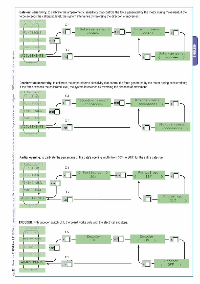
ENCODER: with Encoder switch OFF, the board works only with the electrical endstops.
Encoder
< OFF >
< Encoder>ON
Encoder
< ON >
Gate-run sensitivity: to calibrate the amperometric sensitivity that controls the force generated by the motor during movement; if the force exceeds the calibrated level, the system intervenes by reversing the direction of movement.
< Gate run sens. >-oooo+•
Gate run sens.
< -oooo+ >•
Gate run sens.
< -oooo+ >•
Deceleration sensitivity: to calibrate the amperometric sensitivity that control the force generated by the motor during decelerations; if the force exceeds the calibrated level, the system intervenes by reversing the direction of movement
<Slowdown sens.>-oooooooo+•
Slowdown sens.
< -oooooooo+ >•
Slowdown sens.
< -oooooooo+ >•
< Partial op. >
30%
Partial op.
< 30% >
Partial op.
< 31% >
Partial opening: to calibrate the percentage of the gate’s opening width (from 10% to 80%) for the entire gate-run.
< LANGUAGE >< LANGUAGE >
EnglishEnglishEnglishh
FUNCTIONSFUNCTIONSFUNCTIONFUNCTION
TIMING ADJ.TIMING ADJ.TIMING ADTIMING AD
RADIO USRSRADIO USRSRADIO USRRADIO USR
ADJUSTMENTS
INFOINFOINFOINFO
< LANGUAGE >< LANGUAGE >
EnglishEnglishhh
FUNCTIONSFUNCTIONSFUNCTIONFUNCTION
TIMING ADJ.TIMING ADJ.TIMING ADTIMING AD
RADIO USRSRADIO USRSRADIO USRRADIO USR
ADJUSTMENTS
INFOINFOINFOINFO
< LANGUAGE >< LANGUAGE >
EnglishEnglishhh
FUNCTIONSFUNCTIONSFUNCTIONFUNCTION
TIMING ADJ.TIMING ADJ.TIMING ADTIMING AD
RADIO USRSRADIO USRSRADIO USRRADIO USR
ADJUSTMENTS
INFOINFOINFOINFO
< LANGUAGE >< LANGUAGE >ANGUAANGUA
EnglishEnglishhh
FUNCTIONSFUNCTIONSFUNCTIONFUNCTION
TIMING ADJ.TIMING ADJ.TIMING ADTIMING AD
RADIO USRSRADIO USRSRADIO USRRADIO USR
ADJUSTMENTS
INFOINFOINFOINFO
X 2
X 7
X 8
< NET address >
Disabled
NET address
< Disabled >
NET address
< Master >
NET address
< Slave >
INFO
< Startup Msg >
Saved
- WWW.CAME.IT
ZBK10
< FW Version >
ver. 1.0
<Manoeuvres No.>
16480
ADJUSTMENTS
ADJUSTMENTS
Pag
. 2
42
4
- M
anual
cod
e: 1
19
BV
25
119
BV
25
ver
. 1
.21
.2 0
8/2
011
©
CA
ME
cance
lli a
utom
atic
i s.p
.a.
- Th
e dat
a an
d in
form
atio
n re
por
ted
in t
his
inst
alla
tion
man
ual
are
susc
eptib
le t
o ch
ange
at a
ny t
ime
and
with
out
oblig
atio
n on
CA
ME
cance
lli a
utom
atic
i s.p
.a.
to n
otify
use
rs.
EN
GLIS
H
< NET address >
Disabled
NET address
< Disabled >
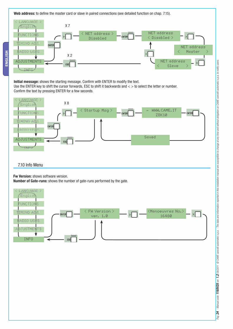
Web address: to define the master card or slave in paired connections (see detailed function on chap. 7.15).
NET address
< Master >
NET address
< Slave >
7.10 Info Menu
Fw Version: shows software version.Number of Gate-runs: shows the number of gate-runs performed by the gate.
< LANGUAGE >< LANGUAGE >
EnglishEnglishhh
FUNCTIONSFUNCTIONSFUNCTIONFUNCTION
TIMING ADJ.TIMING ADJ.TIMING ADTIMING AD
RADIO USRSRADIO USRSRADIO USRRADIO USR
ADJUSTMENTSADJUSTMENTSDJUSTMENDJUSTMEN
INFO
< Startup Msg >
Initial message: shows the starting message. Confirm with ENTER to modify the text.Use the ENTER key to shift the cursor forwards, ESC to shift it backwards and < > to select the letter or number.Confirm the text by pressing ENTER for a few seconds.
Saved
- WWW.CAME.IT
ZBK10
< FW Version >
ver. 1.0
<Manoeuvres No.>
16480
< LANGUAGE >< LANGUAGE >
EnglishEnglishEnglishEnglish
FUNCTIONSFUNCTIONSFUNCTIONFUNCTION
TIMING ADJ.TIMING ADJ.TIMING ADTIMING AD
RADIO USRSRADIO USRSRADIO USRRADIO USR
ADJUSTMENTS
INFOINFOINFOINFO
< LANGUAGE >< LANGUAGE >
EnglishEnglishhh
FUNCTIONSFUNCTIONSFUNCTIONFUNCTION
TIMING ADJ.TIMING ADJ.TIMING ADTIMING AD
RADIO USRSRADIO USRSRADIO USRRADIO USR
ADJUSTMENTS
INFOINFOINFOINFO

E EX 26V 17V 0 10 11TS 1 2 3 3P 4 5 7 2 CX CY C7 C8 2 A B + E D FC FA F
TFMCAME
CAME
CAME
CAME
CAME
CAME
TAM
CAMECAME
CAME
TOP
CAME
CAME
CAME
CAME
TOUCH
TWIN
ATOMO
CAME
CAMECAME
New UserRelated Func.
2-7 Function
n.001 Wait code
.......
Saved
n.001 Existing
Another usr.?
Yes
Another usr.?
No
New User
Related Func.
Only Open
Related Func.
Only Open
Pag
. 2
52
5
- M
anual
cod
e : 1
19
BV
25
119
BV
25
ver
. 1
.21
.2 0
8/2
011
©
CA
ME
cance
lli a
utom
atic
i s.p
.a.
- Th
e dat
a an
d in
form
atio
n re
por
ted
in t
his
inst
alla
tion
man
ual
are
susc
eptib
le t
o ch
ange
at a
ny t
ime
and
with
out
oblig
atio
n on
CA
ME
cance
lli a
utom
atic
i s.p
.a.
to n
otify
use
rs.
EN
GLIS
H
New UserRelated Func.
2-7 Function
1) From the Radio Users menu, select “ New User”.Press ENTER to confirm.
2) Choose the function you wish to assign to the user. Press ENTER to confirm ...
n.001 Wait code
.......
Saved
3) ...you will be prompted to input a code.Send the code using the transmitter button...
4) ...once the code is inputted, the read out will say “Saved”...
n.001 Existing
Another usr.?
Yes
5) ...then you will be asked whether you wish to input a new code or not.By selecting and confirming “No”, the user input procedure will be terminated.
6) ......by selecting and confirming “Yes”, you will begin again from point 2.
Another usr.?
No
7.11 Decoding card
Insert the AF radio card which command the operator and insert, modify or remove any users using the transmitter.Insert the memory roll to save and upload the registered users onto another card.
AF Card
Memory roll
7.12 Inputting users
...or “existing” (if the code has already been inputted).
New User
Related Func.
Only Open
Related Func.
Only Open
See instruction sheet in AF43SR radiofrequency card box
See instructions on packaging
Modify UserModify User
n.001 In use
n.002 Existing
2-7 Function
Modify User
n.002 In use
n.002 Existing
Only Open
Gate run Adj.Press a key
Please wait.... Please wait....
Modify User
Pag
. 2
62
6
- M
anual
cod
e: 1
19
BV
25
119
BV
25
ver
. 1
.21
.2 0
8/2
011
©
CA
ME
cance
lli a
utom
atic
i s.p
.a.
- Th
e dat
a an
d in
form
atio
n re
por
ted
in t
his
inst
alla
tion
man
ual
are
susc
eptib
le t
o ch
ange
at a
ny t
ime
and
with
out
oblig
atio
n on
CA
ME
cance
lli a
utom
atic
i s.p
.a.
to n
otify
use
rs.
EN
GLIS
H
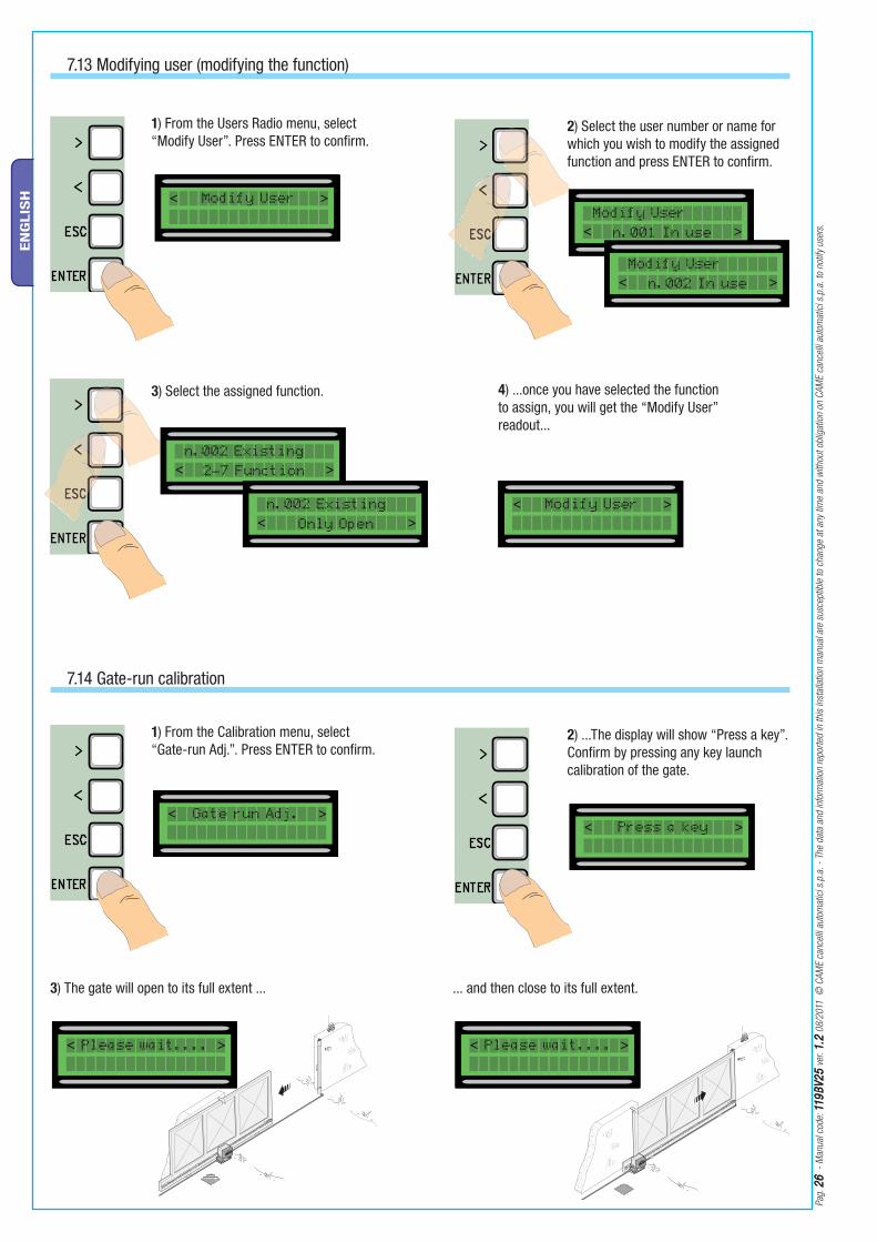
7.13 Modifying user (modifying the function)
7.14 Gate-run calibration
Modify UserModify User
n.001 In use
1) From the Users Radio menu, select “Modify User”. Press ENTER to confirm.
2) Select the user number or name for which you wish to modify the assigned function and press ENTER to confirm.
n.002 Existing
2-7 Function
3) Select the assigned function. 4) ...once you have selected the function to assign, you will get the “Modify User” readout...
Modify User
n.002 In use
n.002 Existing
Only Open
Gate run Adj.
1) From the Calibration menu, select “Gate-run Adj.”. Press ENTER to confirm.
2) ...The display will show “Press a key”. Confirm by pressing any key launch calibration of the gate.
3) The gate will open to its full extent ... ... and then close to its full extent.
Press a key
Please wait.... Please wait....
Modify User
3P 4 5 7 2 CX CY C7 C8 2 A B + E D FC FA 3P 4 5 7 2 CX CY C7 C8 2 A B + E D FC FA
NET address
Disabled
NET address
Disabled
NET address
Master
NET address
Disabled
NET address
Slave
Pag
. 2
72
7
- M
anual
cod
e : 1
19
BV
25
119
BV
25
ver
. 1
.21
.2 0
8/2
011
©
CA
ME
cance
lli a
utom
atic
i s.p
.a.
- Th
e dat
a an
d in
form
atio
n re
por
ted
in t
his
inst
alla
tion
man
ual
are
susc
eptib
le t
o ch
ange
at a
ny t
ime
and
with
out
oblig
atio
n on
CA
ME
cance
lli a
utom
atic
i s.p
.a.
to n
otify
use
rs.
EN
GLIS
H
7.15 Net address
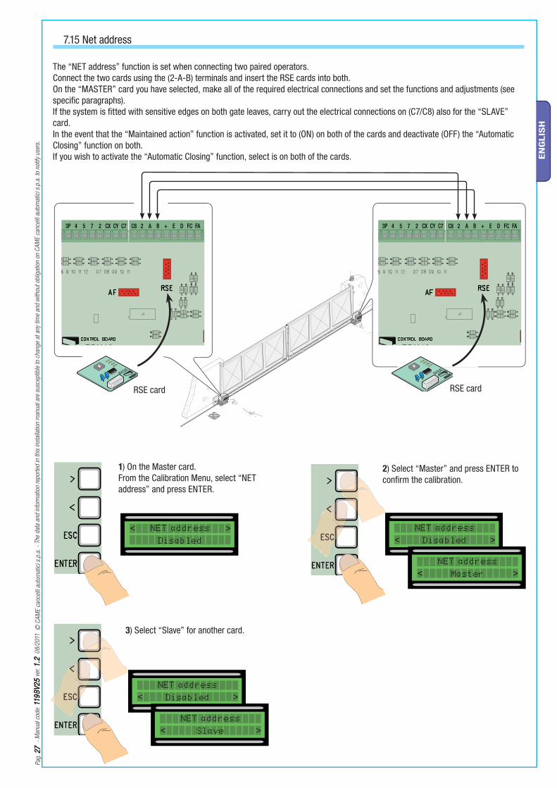
1) On the Master card.From the Calibration Menu, select “NET address” and press ENTER.
2) Select “Master” and press ENTER to confirm the calibration.
RSE card
The “NET address” function is set when connecting two paired operators.Connect the two cards using the (2-A-B) terminals and insert the RSE cards into both.On the “MASTER” card you have selected, make all of the required electrical connections and set the functions and adjustments (see specific paragraphs).If the system is fitted with sensitive edges on both gate leaves, carry out the electrical connections on (C7/C8) also for the “SLAVE” card.In the event that the “Maintained action” function is activated, set it to (ON) on both of the cards and deactivate (OFF) the “Automatic Closing” function on both.If you wish to activate the “Automatic Closing” function, select is on both of the cards.
RSE card
3) Select “Slave” for another card.
NET address
Disabled
NET address
Disabled
NET address
Master
NET address
Disabled
NET address
Slave
Pag
. 2
82
8
- M
anual
cod
e: 1
19
BV
25
119
BV
25
ver
. 1
.21
.2 0
8/2
011
©
CA
ME
cance
lli a
utom
atic
i s.p
.a.
- Th
e dat
a an
d in
form
atio
n re
por
ted
in t
his
inst
alla
tion
man
ual
are
susc
eptib
le t
o ch
ange
at a
ny t
ime
and
with
out
oblig
atio
n on
CA
ME
cance
lli a
utom
atic
i s.p
.a.
to n
otify
use
rs.
EN
GLIS
H
8 Safety instructions
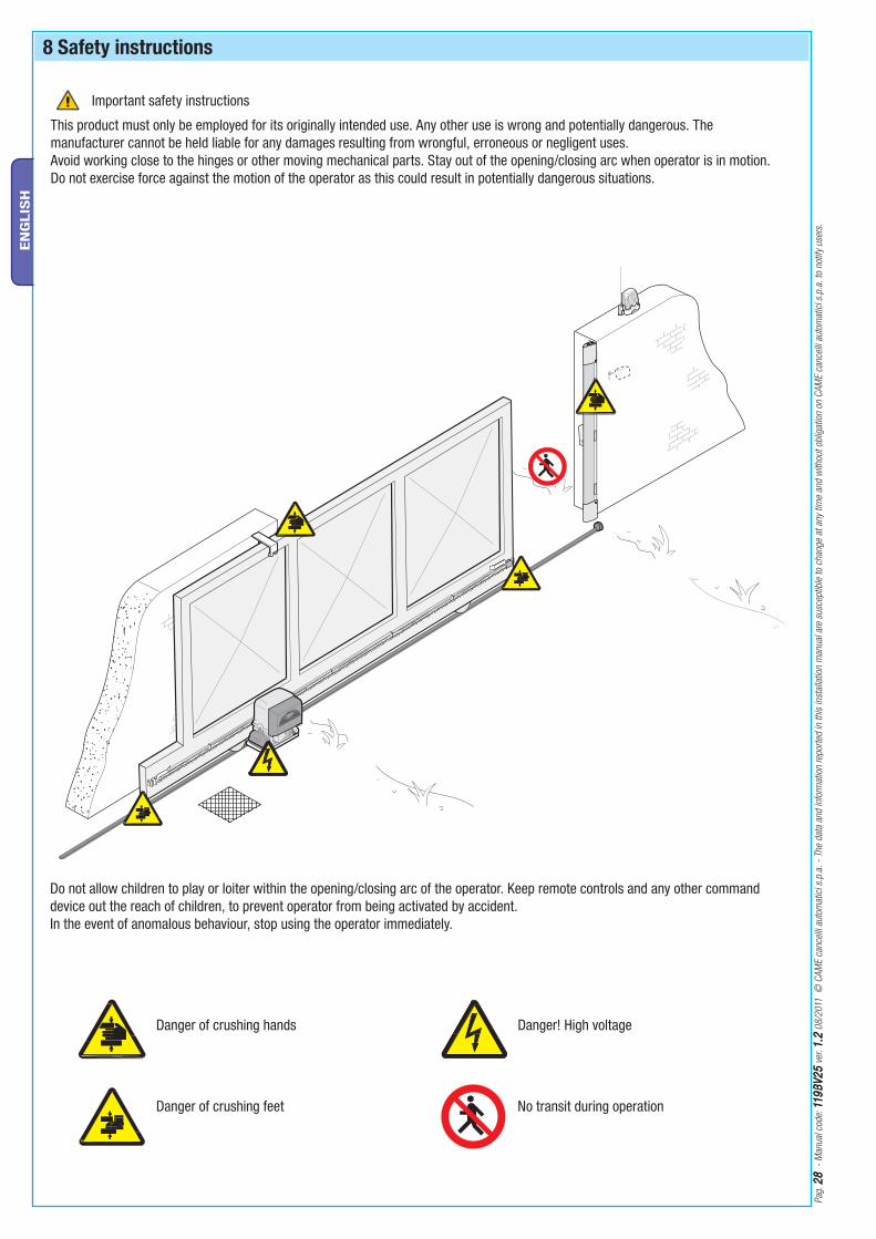
This product must only be employed for its originally intended use. Any other use is wrong and potentially dangerous. The manufacturer cannot be held liable for any damages resulting from wrongful, erroneous or negligent uses.Avoid working close to the hinges or other moving mechanical parts. Stay out of the opening/closing arc when operator is in motion.Do not exercise force against the motion of the operator as this could result in potentially dangerous situations.
Do not allow children to play or loiter within the opening/closing arc of the operator. Keep remote controls and any other command device out the reach of children, to prevent operator from being activated by accident.In the event of anomalous behaviour, stop using the operator immediately.
Danger of crushing hands
Danger of crushing feet
Danger! High voltage
No transit during operation
Important safety instructions

Pag
. 2
92
9
- M
anual
cod
e : 1
19
BV
25
119
BV
25
ver
. 1
.21
.2 0
8/2
011
©
CA
ME
cance
lli a
utom
atic
i s.p
.a.
- Th
e dat
a an
d in
form
atio
n re
por
ted
in t
his
inst
alla
tion
man
ual
are
susc
eptib
le t
o ch
ange
at a
ny t
ime
and
with
out
oblig
atio
n on
CA
ME
cance
lli a
utom
atic
i s.p
.a.
to n
otify
use
rs.
EN
GLIS
H
9 Maintenance
9.1 Periodic maintenance
Periodic maintenance to be carried out by the end-user is as follows: wipe clean the glass surface of the photocells; check that the safety devices work properly; remove any obstructions.We suggest checking the state of lubrication and tightness of the anchoring screws on the operator.-To check the efficiency of the safety devices, move an object in front of the photocells when gate is closing. If the operator inverts the motion or stops, the photocells are working properly.This is the only maintenance procedure to be carried out with the power source connected.-Before performing any maintenance procedures, cut off the main power, to prevent possible accidents due to gate movement.-To clean the photocells use a water dampened cloth. Do not use solvents or other chemical products which may ruin the devices.-In the event of any strange vibrations or squeaking, lubricate the joints with grease, as shown in the diagram.-Make sure there are no plants within the photocell’s beam, and that the gate motion is free of any obstacles.
9.2 Trouble shooting
MALFUNCTIONS POSSIBLE CAUSES CHECK AND REMEDIES
The gate will not open nor close
• There is no power• The gearmotor is in release mode and the release door is open • The transmitter’s batteries are run down• The transmitter is broken• The stop button is either stuck or broken• The opening/closing button or the key selector are stuck• Fhotocells in partial stop mode
• Check that the power is up• Lock the gearmotor (chap. 5.8)• Replace batteries• Call assistance• Call assistance• Call assistance• Call assistance
The gate opens but will not close
• The photocells are engaged
• Sensitive edge triggered
• Check that photocells are clean and in good working order
• Call assistance
The gate closes but will not open
• Sensitive edge triggered • Call assistance
The flasher does not work
• The bulb is burnt • Call assistance

Pag
. 3
03
0
- M
anual
cod
e: 1
19
BV
25
119
BV
25
ver
. 1
.21
.2 0
8/2
011
©
CA
ME
cance
lli a
utom
atic
i s.p
.a.
- Th
e dat
a an
d in
form
atio
n re
por
ted
in t
his
inst
alla
tion
man
ual
are
susc
eptib
le t
o ch
ange
at a
ny t
ime
and
with
out
oblig
atio
n on
CA
ME
cance
lli a
utom
atic
i s.p
.a.
to n
otify
use
rs.
EN
GLIS
H
9.3 Extra-ordinary maintenance
The following table serves to note down any extraordinary maintenance, repairs or improvements performed by specialised firms.N.B.: Any extraordinary maintenance must be performed by specialised technicians.
Extra-ordinary maintenance log
Date Notes Signature
Periodic maintenance log for end-user (every 6 moths)
Installer’s stamp Operator name
Date of job
Technician’s signature
Requester’s signature
Job performed __________________________________________________________________________________________________________________________________________________________________________________________
Installer’s stamp Operator name
Date of job
Technician’s signature
Requester’s signature
Job performed __________________________________________________________________________________________________________________________________________________________________________________________
Installer’s stamp Operator name
Date of job
Technician’s signature
Requester’s signature
Job performed __________________________________________________________________________________________________________________________________________________________________________________________
Pag
. 3
13
1
- M
anual
cod
e : 1
19
BV
25
119
BV
25
ver
. 1
.21
.2 0
8/2
011
©
CA
ME
cance
lli a
utom
atic
i s.p
.a.
- Th
e dat
a an
d in
form
atio
n re
por
ted
in t
his
inst
alla
tion
man
ual
are
susc
eptib
le t
o ch
ange
at a
ny t
ime
and
with
out
oblig
atio
n on
CA
ME
cance
lli a
utom
atic
i s.p
.a.
to n
otify
use
rs.
EN
GLIS
H
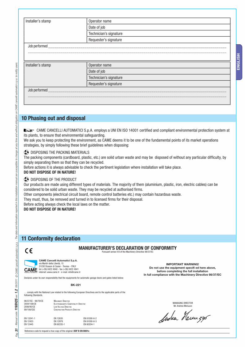
10 Phasing out and disposal
Installer’s stamp Operator name
Date of job
Technician’s signature
Requester’s signature
Job performed __________________________________________________________________________________________________________________________________________________________________________________________
Installer’s stamp Operator name
Date of job
Technician’s signature
Requester’s signature
Job performed __________________________________________________________________________________________________________________________________________________________________________________________
CAME CANCELLI AUTOMATICI S.p.A. employs a UNI EN ISO 14001 certified and compliant environmental protection system at its plants, to ensure that environmental safeguarding.We ask you to keep protecting the environment, as CAME deems it to be one of the fundamental points of its market operations strategies, by simply following these brief guidelines when disposing:
DISPOSING THE PACKING MATERIALSThe packing components (cardboard, plastic, etc.) are solid urban waste and may be disposed of without any particular difficulty, by simply separating them so that they can be recycled.Before actions it is always advisable to check the pertinent legislation where installation will take place.DO NOT DISPOSE OF IN NATURE!
DISPOSING OF THE PRODUCTOur products are made using different types of materials. The majority of them (aluminium, plastic, iron, electric cables) can be considered to be solid urban waste. They may be recycled at authorised firms. Other components (electrical circuit board, remote control batteries etc.) may contain hazardous waste. They must, thus, be removed and turned in to licensed firms for their disposal.Before acting always check the local laws on the matter.DO NOT DISPOSE OF IN NATURE!
CAME Cancelli Automatici S.p.A.
via Martiri della Libertà, 15 31030 Dosson di Casier - Treviso - ITALY tel (+39) 0422 4940 - fax (+39) 0422 4941 internet: www.came.it - e-mail: [email protected]
Declares under its own responsibility that the equipments for automatic garage doors and gates listed below:
… comply with the National Law related to the following European Directives and to the applicable parts of the following Standards.
98/37/CE - 98/79/CE MACHINERY DIRECTIVE
2004/108/CE ELECTROMAGNETIC COMPATIBILITY DIRECTIVE
2006/95/CE LOW VOLTAGE DIRECTIVE
89/106/CEE CONSTRUCTION PRODUCTS DIRECTIVE
EN 13241-1 EN 12635 EN 61000-6-2 EN 12453 EN 12978 EN 61000-6-3 EN 12445 EN 60335-1 EN 60204-1
BK-221
11 Conformity declaration
Reference code to request a true copy of the original: DDF B EN B001c
MANUFACTURER’S DECLARATION OF CONFORMITYPursuant annex II B of the Machinery Directive 98/37/EC
IMPORTANT WARNING!
Do not use the equipment specifi ed here above,
before completing the full installation
In full compliance with the Machinery Directive 98/37/EC
MANAGING DIRECTORMr. Andrea Menuzzo

CAMECAME FranceFrance S.a. S.a. FRANCE7, Rue Des HarasZ.i. Des Hautes Patures92737 Nanterre CedexNanterre Cedex
(+33) 0 825 825 874 (+33) 1 46 13 05 00
GERMANY CAME Gmbh Seefeld CAME Gmbh SeefeldAkazienstrasse, 9
16356 Seefeld Seefeld Bei Berlin (+49) 33 3988390
(+49) 33 39883985
CAME Automatismes S.a. CAME Automatismes S.a. FRANCE3, Rue Odette Jasse13015 MarseilleMarseille
(+33) 0 825 825 874 (+33) 4 91 60 69 05
U.A.E. CAME Gulf Fze CAME Gulf FzeOffi ce No: S10122a2o210
P.O. Box 262853 Jebel Ali Free Zone - Dubai Dubai
(+971) 4 8860046 (+971) 4 8860048
CAME Automatismos S.a. CAME Automatismos S.a. SPAINC/juan De Mariana, N. 17-local28045 Madrid Madrid
(+34) 91 52 85 009 (+34) 91 46 85 442
RUSSIA CAME Rus CAME RusUmc Rus LlcUmc Rus Llc
Ul. Otradnaya D. 2b, Str. 2, offi ce 219 127273, MoscowMoscow
(+7) 495 739 00 69 (+7) 495 739 00 69 (ext. 226)
CAME United Kingdom Ltd. CAME United Kingdom Ltd. GREAT BRITAINUnit 3 Orchard Business ParkTown Street, SandiacreNottingham Nottingham - Ng10 5bp
(+44) 115 9210430 (+44) 115 9210431
PORTUGAL CAME Portugal CAME Portugal Ucj Portugal Unipessoal LdaUcj Portugal Unipessoal Lda
Rua Liebig, nº 23 2830-141 BarreiroBarreiro
(+351) 21 207 39 67 (+351) 21 207 39 65
CAME Group Benelux S.a. CAME Group Benelux S.a. BELGIUMZoning Ouest 77860 Lessines Lessines
(+32) 68 333014 (+32) 68 338019
INDIA CAME India CAME India Automation Solutions Pvt. LtdAutomation Solutions Pvt. Ltd
A - 10, Green Park 110016 - New DelhiNew Delhi
(+91) 11 64640255/256 (+91) 2678 3510
CAME Americas Automation Llc CAME Americas Automation Llc U.S.A11345 NW 122nd St. MedleyMedley, FL 33178
(+1) 305 433 3307 (+1) 305 396 3331
ASIA CAME Asia Pacific CAME Asia Pacific 60 Alexandra Terrace #09-09
Block C, The ComTech118 502 SingaporeSingapore
(+65) 6275 0249 (+65) 6274 8426
CAME Gmbh CAME Gmbh GERMANYKornwestheimer Str. 3770825 Korntal Korntal Munchingen Bei Stuttgart
(+49) 71 5037830 (+49) 71 50378383
CAME Cancelli Automatici S.p.a. CAME Cancelli Automatici S.p.a. ITALYVia Martiri Della Libertà, 1531030 Dosson Di Casier Dosson Di Casier (Tv)
(+39) 0422 4940 (+39) 0422 4941
Informazioni Commerciali 800 848095
ITALY CAME Sud s.r.l.CAME Sud s.r.l.Via F. Imparato, 198
Centro Mercato 2, Lotto A/7 80146 Napoli Napoli
(+39) 081 7524455 (+39) 081 7529190
CAME Service Italia S.r.l. CAME Service Italia S.r.l. ITALYVia Della Pace, 2831030 Dosson Di Casier Dosson Di Casier (Tv)
(+39) 0422 383532 (+39) 0422 490044
Assistenza Tecnica 800 295830Assistenza Tecnica 800 295830
ITALY CAME Global Utilities s.r.l.CAME Global Utilities s.r.l.Via E. Fermi, 31
20060 GessateGessate (Mi) (+39) 02 95380366 (+39) 02 95380224
01_2011
www.came.com www.came.it
En
glish
En
glish
-
Man
ual
cod
e: 1
19
BV
25
119
BV
25
ver
. 1
.21
.2 0
8/2
011
© C
AM
E ca
nce
lli a
utom
atic
i s.p
.a.
The
dat
a an
d in
form
atio
n re
por
ted
in t
his
inst
alla
tion
man
ual
are
susc
eptib
le t
o ch
ange
at a
ny t
ime
and
with
out
oblig
atio
n on
CA
ME
cance
lli a
utom
atic
i s.p
.a.
to n
otify
use
rs.