blackout buster - produktinfo.conrad.com · manual. 2. general safety ... do not work alone in any...
TRANSCRIPT
LL
--
=
SONTRONIC
BLACKOUT BUSTER
OPERATION- UND SERVICEMANUAL
A

T
-
Ir
-
-
-
PK Electronics Blackout Buster
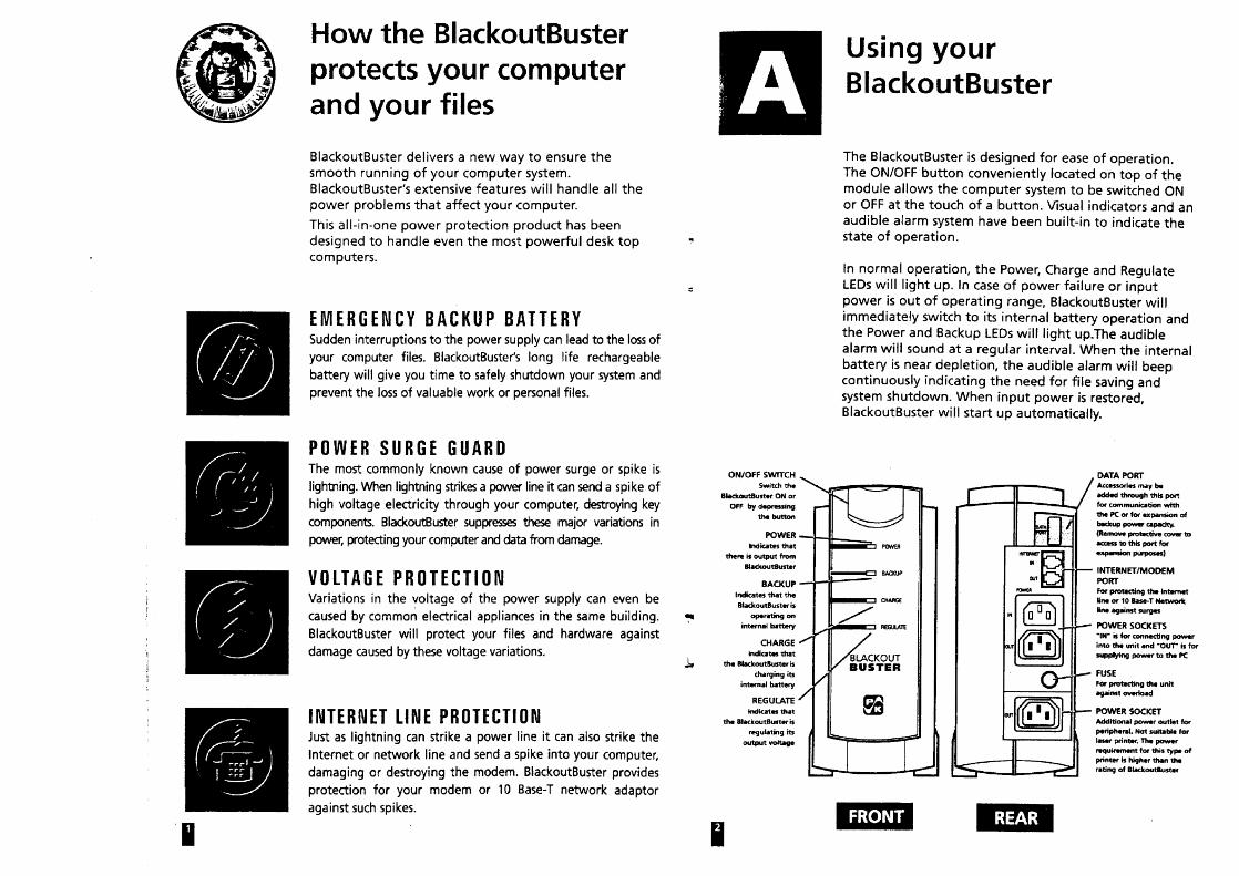
1. System Description
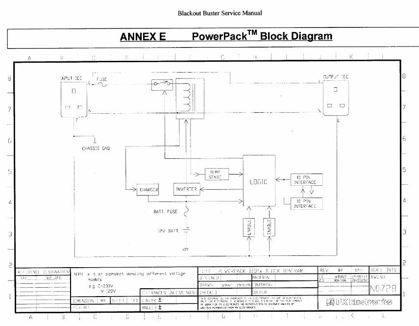
Please refer to BlackoutBuster’s Technical Specifications & Product DescriptionManual.
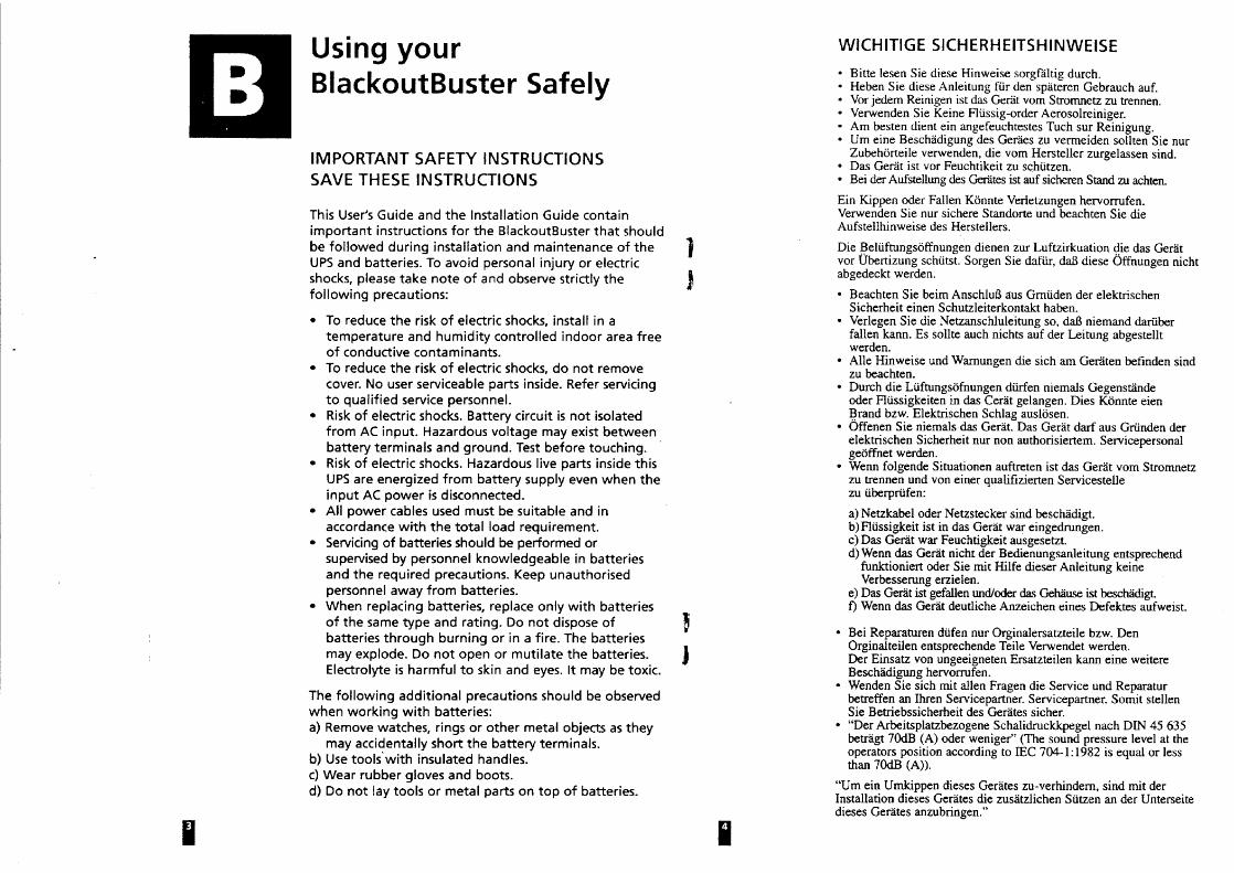
2. General Safety Considerations
Please observe the following guidelines:
Do not work alone in any potentially hazardous conditions.Always inform your co-workers of hazardous voltages or conditions that pose athreat to yours and/or their safety.Always be on the lookout for possible hazards such as worn-out insulation,moisture, non-grounded power source, faulty or poorly maintain electrical safetydevice such as circuit breakers and residual current breakers etc.Do not operate UPS without their safety covers.Before starting the UPS, ensure that all personnel are not exposed to any potentiallyhazardous voltages.Do not remove or bypass any safety device. Fuses & Circuit Breakers etc. aredesigned into the system for safety reasons.
ever assume rom a clrculwork. Always check with a test-pen or voltmeter. I
Always think about safety. With good housekeeping and preventive practices, we cankeep our workplace safe.
Care for our Environment:
3. Servicing & Maintaining BlackoutBusterTM
The Servicing and maintenance of Blackout Buster (BOB), PowerPack andaccessories is done at the board level. The only components that are replaceableare the surge protector- Metal Oxide Varistor (MOV), battery and fuses. For serviceand warranty policy, please consult PK Electronics’ Customer Service Center foryour country / region.
SCJNTRONIC GmbH Zur Deutschen Einheit 3/B D-81929 Mijnchen Tel.:089 99301160 Fax:089 9373113-
-
-
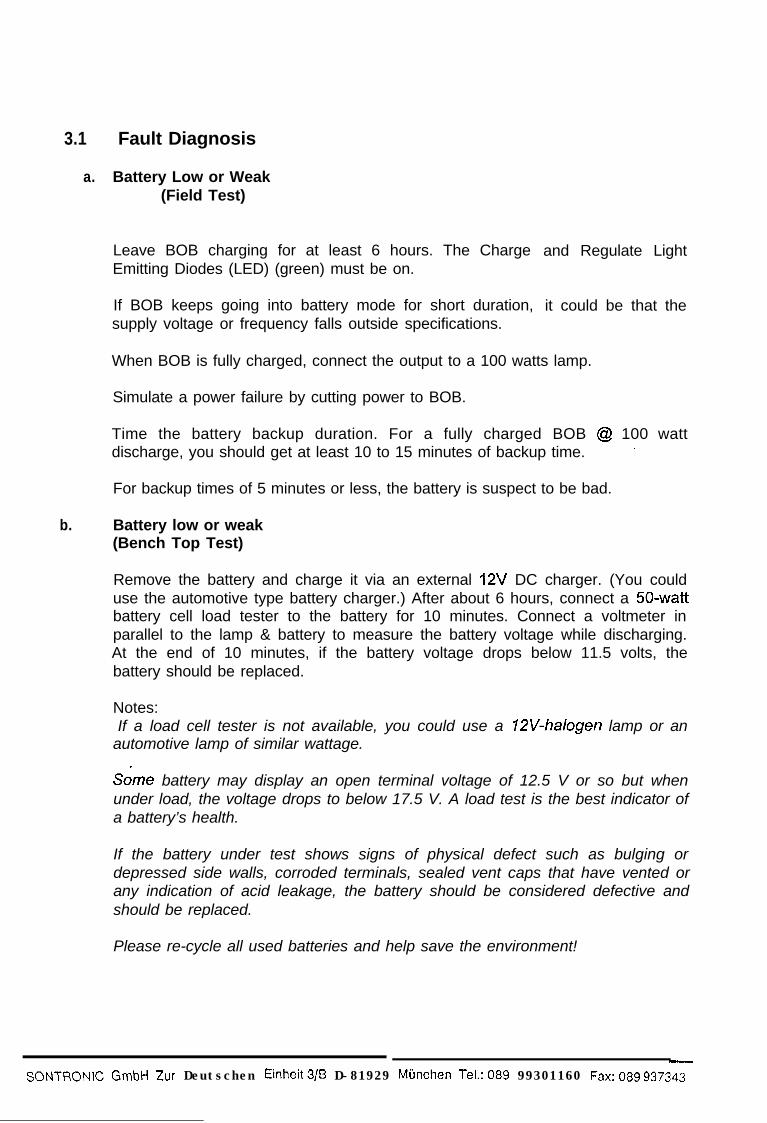
3.1 Fault Diagnosis
a. Battery Low or Weak(Field Test)
Leave BOB charging for at least 6 hours. The ChargeEmitting Diodes (LED) (green) must be on.
If BOB keeps going into battery mode for short duration,supply voltage or frequency falls outside specifications.
and Regulate Light
it could be that the
When BOB is fully charged, connect the output to a 100 watts lamp.
Simulate a power failure by cutting power to BOB.
Time the battery backup duration. For a fully charged BOB @ 100 wattdischarge, you should get at least 10 to 15 minutes of backup time. *
For backup times of 5 minutes or less, the battery is suspect to be bad.
b. Battery low or weak(Bench Top Test)
Remove the battery and charge it via an external 12V DC charger. (You coulduse the automotive type battery charger.) After about 6 hours, connect a 50-wattbattery cell load tester to the battery for 10 minutes. Connect a voltmeter inparallel to the lamp & battery to measure the battery voltage while discharging.At the end of 10 minutes, if the battery voltage drops below 11.5 volts, thebattery should be replaced.
Notes:
. .
If a load cell tester is not available, you could use a 12V-halogen lamp or anautomotive lamp of similar wattage.
Some battery may display an open terminal voltage of 12.5 V or so but whenunder load, the voltage drops to below 17.5 V. A load test is the best indicator ofa battery’s health.
If the battery under test shows signs of physical defect such as bulging ordepressed side walls, corroded terminals, sealed vent caps that have vented orany indication of acid leakage, the battery should be considered defective andshould be replaced.
Please re-cycle all used batteries and help save the environment!
-
- SC-JNTRONIC GmbH Zur Deutschen Einheit3/8 D-81929 Miinchen Tel.:089 99301160 Fax:089 937343
C. Battery Charger / Battery Fuse
h
Sympfom: Battery low or dead battery. Examp\e: while simulating a powerfailure, BOB shutdown immediately or battery backup time is very short. Note: afaulty charger if not corrected may damage the bsftery over time.
. _
-
To test charger, we need to connect a voltmeter afloss the battery and monitora rise in voltage when input power is supplied.
--_-
14
Ir
Open BOB (Refer to Annex A: Pictorial Guide on DisassemblingBlackoutBuster). Next connect the input power cord but do not energize (turnpower on). Place your voltmeter probes across the battery terminals. A goodbattery should indicate a reading of about 12.5 volts. Next supply input power toBOB. The charge LED should come on. Monitor the voltmeter readings, it shouldrise over the next few minutes. If there is no change at all, replace the batterywith a good battery and repeat the fest. If the voltage does not climb upwards,the charger is faulty. Change the main circuit board. Nofe: The rate of voltagerise when charging depends on the state of baftety under charge.
d.
Battery Fuse: Two* 30A fuses protect BOB’s battery. The only know p,ossiblecondition that could causes this fuz to blow is an overload of BOB in BatteryMode (DC Mode). Should this occur, please contact PK Electronics CustomerService Center listed on the back ofthis manual.
Voltage Regulator
Symptom: BOB keeps going into bttery backup mode when utility power is stillwithin specifications (170-270 VAG. The regulate LED does not light up.
You will need a variable transformer to do this test. Connect the output of thevariable transformer to the input 0: BOB. Connect the probes of a voltmeter tothe output of BOB. Set the variale transformer to 23OVac. Power on BOB.Monitor the reading of the voltmeter. It should show 230Vac. Now trim down thevariable transformer to about 200V and monitor the voltmeter reading. As youtrim up/down the variable transformer, the output of BOB will fluctuate between205 V and 245 V. If it is outside this range, the voltage regulator is faulty.Change the main circuit board.
3 e. lnverter Output
Symptom: When utility power fails, BOB shutdown immediately.
-
I_
-
After you have confirmed that this is not due to a battery fault or charger fault,connect a RMS (root mean square) voltmeter to the output of BOB. Power up inbattery mode. The voltmeter should read 230Vac. If the reading is low, below205 V or if BOB will not startup in battery mode (DC Mode) the inverter is faulty.Change the main circuit board.
*Revised on 3111198
---C-U,..-
SONTRONIC GmbH Zur Oeulschen Einheit 3/B D-81929 Mijnchen Tel.: 089 gg301160 ~~~~ 089 937342-
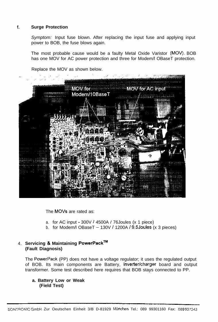
f. Surge Protection
Symptom: Input fuse blown. After replacing the input fuse and applying inputpower to BOB, the fuse blows again.
The most probable cause would be a faulty Metal Oxide Varistor (MOV). BOBhas one MOV for AC power protection and three for Modem/l OBaseT protection.
Replace the MOV as shown below.
4.
The MOVs are rated as:
a. for AC input - 300V / 4500A / 76Joules (x 1 piece)b. for Modem/l OBaseT - 130V / 1200A / 9.5Joules (x 3 pieces)
Servicing & Maintaining PowerPackTM(Fault Diagnosis)
The PowerPack (PP) does not have a voltage regulator; it uses the regulated outputof BOB. Its main components are Battery, inverter/charger board and outputtransformer. Some test described here requires that BOB stays connected to PP.
a. Battery Low or Weak(Field Test)
SONTRONIC GmbH Zur Oeutschen Einheit 3/B D-81929 Miinchen Tel.: 089 99301160 Fax: 089 937343
b.
C.
For backup times of 5
Battery low or weak(Bench Top Test)
Refer to section 3.1 b
Charger
Refer to section 3.1 c
Note: The PP gets its input power through BOB’s Voltage Regulator. Thecharge LED will only light up when connected to BOB and BOB is turned on.For testing, you could connect the input power directly to PP.
d. lnverter
To test a PP battery, you need* a custom-made connection cable. (Refer toAnnex C: Custom Made Cable for Testing PowerPack). Connect the cablebetween BOB & PP. Do not forget to connect the Data Cable between BOBand PP. Connect a loo-watt lamp to the output of PP. Simulate a utilitypower failure. BOB and PP should go into battery mode (DC Mode). Time thebattery backup duration. For a fully charged PP @ 100 watt discharge, youshould get at least 10 to 15 minutes of backup time.
minutes or less, the battery is suspect to be bad.
Sympfom: When utility power fails, BOB shutdown immediately or there is acontinues beep from BOB.
To test a PP inverter, you need to custom make a connection cable. (Refer toAnnex C: Custom Made Cable for Testing PowerPack). Connect the cablebetween BOB & PP. Next connect a 100 watt lamp to the output of PP. Inparallel to this lamp, connect a RMS (root mean square) voltmeter. Do notforget to connect the Data Cable between BOB and PP. Power up BOB inbattery mode. PP should also power up. The voltmeter should read 230VAC.If the reading is low, below 205 V or if BOB will not startup in battery mode(DC Mode) the inverter is faulty. Change the main circuit board.
5. ServiCing & Maintaining SmartPackTM
SmartPack contains no serviceable part within. The fuse is rated 5A, slow blow. Inmost cases, it is treated as a disposable accessory. However depending onconditions, the main circuit board may be replaceable. Please check with PKElectronics Customer Care Center as listed on the back of this manual.
a. Testing SmartPack
Connect SmartPack as in Annex B (How to use SmartPack to controlBlackoutBuster)
l
Revised on 20/10/98
s(yq~RoNlC GmbH Zur Deutschen Einheit3/B D-81929 Mijnchen Tel.:08999301160 Fax: 089 937343

--
m!m
I
6.
7.
If you are unable to establish communications with SmartPack and you arecertain that the serial port of the PC you are using is working correctly then it issafe to assume that SmartPack has cease to function.
Servicing & Maintaining MicroPackTMThe MicroPack contains no serviceable parts within. To test that the MicroPack isfunctioning correctly, carry out the following procedure:
Connect MicroPack to a PC that you know has run PowerMon II without anyproblems. If PowerMON II reports that BOB has a battery low signal but BOB isoperating in Utility Power Mode (AC Mode) then we can assume that MicroPack hasceased to function.
SummaryFor the information on servicing the BlackoutBuster, PowerPack and accessory,please contact PK Electronics Customer Service Cenfers listed on the back of thismanual. Alternatively, you could email to [email protected]
a-
SONTRONIC GmbH Zur Deutschen Einhei t 3 /B D-81929 Mfinchen Tel.:089 9 9 3 0 1 1 6 0 Fax:089 937&t:!
-
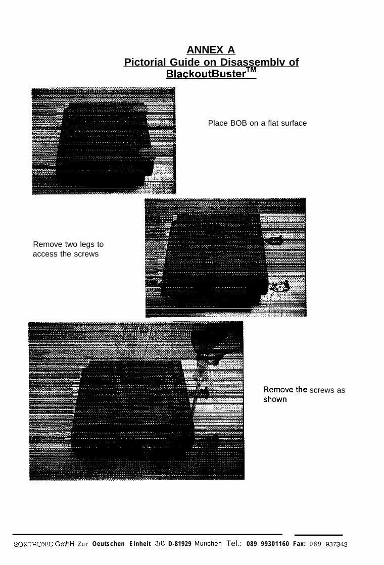
ANNEX APictorial Guide on Disassemblv of
BlackoutBusterTM
-
Place BOB on a flat surface
Remove two legs toaccess the screws
screws as
- SONTRON~C GmbH Zur Oeutschen Einheit 3/B D-81929 Mijnchen Tel.: 089 99301160 Fax: 089 937343
-
-
-
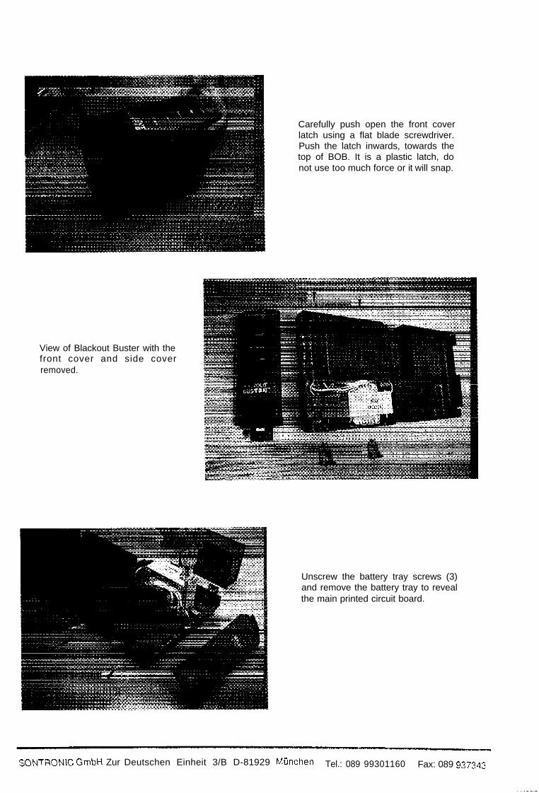
View of Blackout Buster with thefront cover and side coverremoved.
Carefully push open the front coverlatch using a flat blade screwdriver.Push the latch inwards, towards thetop of BOB. It is a plastic latch, donot use too much force or it will snap.
Unscrew the battery tray screws (3)and remove the battery tray to revealthe main printed circuit board.
SONTPCN\C GmbH Zur Deutschen Einheit 3/B D-81929 Mijnchen Tel.: 089 99301160 Fax: 089 937343-
-
-
-
mm
_
3
-
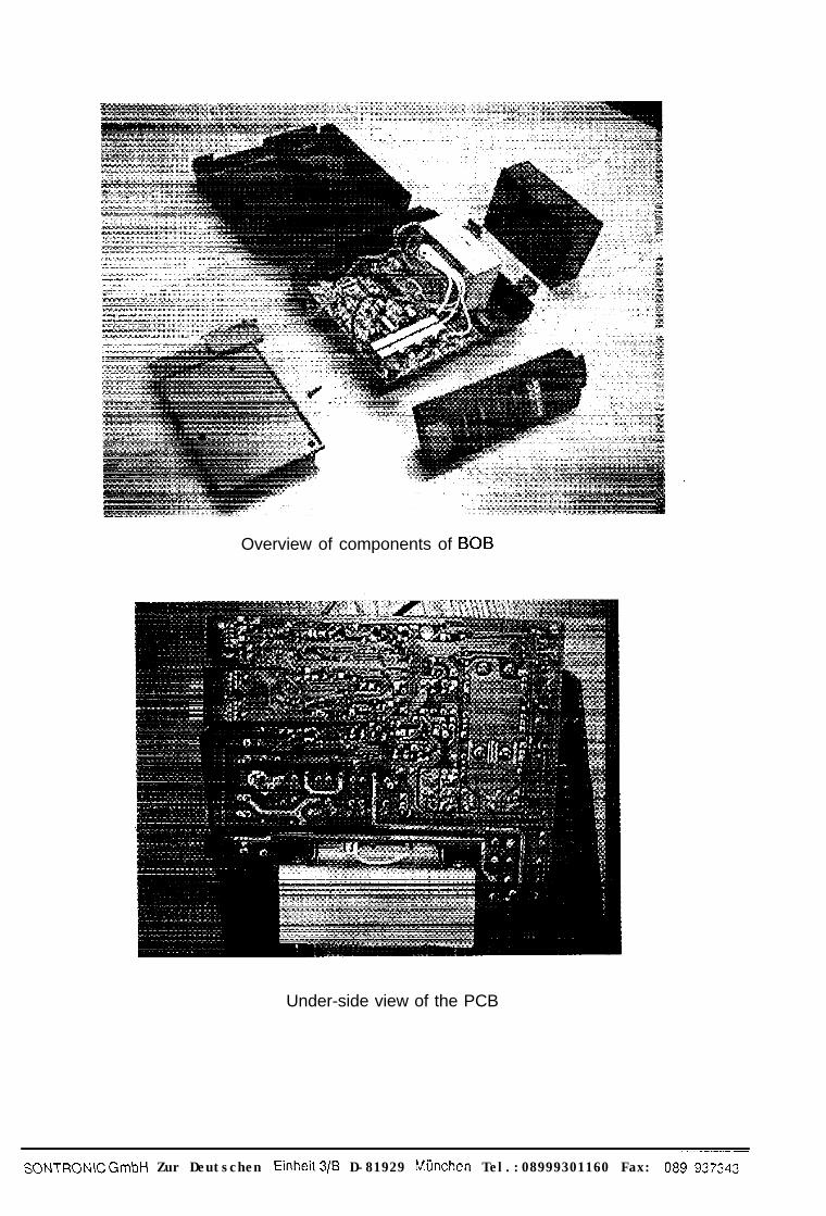
Overview of components of BC>B
Under-side view of the PCB
---.--_-_SONTRONIC GmbH Zur Deutschen Einheit3/B D-81929 Mijnchen Tel.:08999301160 Fax: 089 937343

Close-up view of the transformer
* Note: PowerPack disassembly is similar to BOB
_~. ~~ -~-.-
SONTRONIC GmbH Zur Deutschen Einheit3/B D-81929 Mijnchen Tel.:089993011 60 Fax:089 937343
I -
-
-
e=4
-
--
LI
3
-
--
-
-
-
-
-
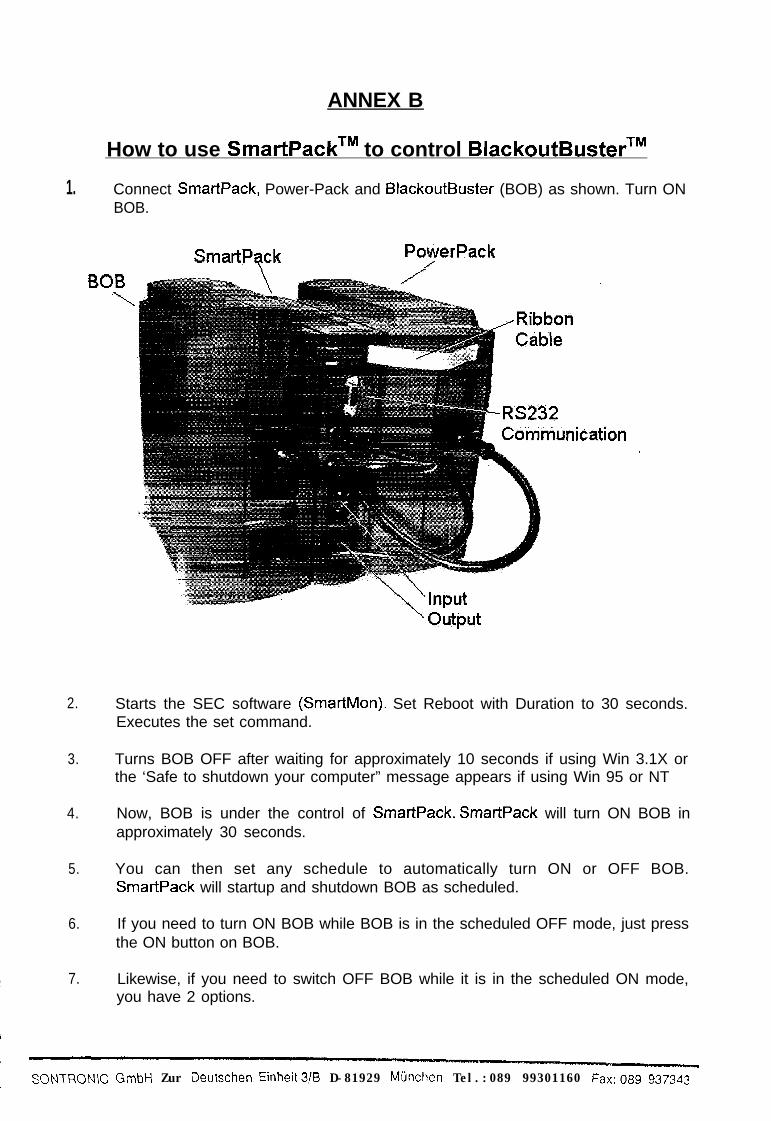
ANNEX B
How to use SmartPackTM to control BlackoutBusterTM
1. Connect SmartPack, Power-Pack and BlackoutBuster (BOB) as shown. Turn ONBOB.
SmartPack PotieiPack/BOB\
’ Output
2.
3.
4.
5.
6.
7.
Starts the SEC software (SmartMon). Set Reboot with Duration to 30 seconds.Executes the set command.
Turns BOB OFF after waiting for approximately 10 seconds if using Win 3.1X orthe ‘Safe to shutdown your computer” message appears if using Win 95 or NT
Now, BOB is under the control of SmartPack. SmartPack will turn ON BOB inapproximately 30 seconds.
You can then set any schedule to automatically turn ON or OFF BOB.SmartPack will startup and shutdown BOB as scheduled.
If you need to turn ON BOB while BOB is in the scheduled OFF mode, just pressthe ON button on BOB.
Likewise, if you need to switch OFF BOB while it is in the scheduled ON mode,you have 2 options.
SONTRON\C GmbH Zur Oeutschen Einheit3/8 D-81929 Mijnchen Tel.:089 99301160 Fax:089 937343

lli
--.-
a) Issues a OFF command (“Shutdown after Delay”) from SmartMon,
b) Remove the ribbon cable connecting BOB and SmartPack.
Note:7. To have SmartPack controls BOB again, you need to perform the above
steps I to 4. *2. SmattMon will not register any load readings if
output socket other than SmartPack.3. For software version 7.3, it allows BOB to start
failure shutdown. SmartPack is still in control.
the load is connected to
automa tically after power
l Revised on 20/10/98
- SC-JNTRONIC Gmbl-i Zur Deutschen Einheit3/B D-81929 Mijnchen Tel.:089 99301160 Fax:089 937343
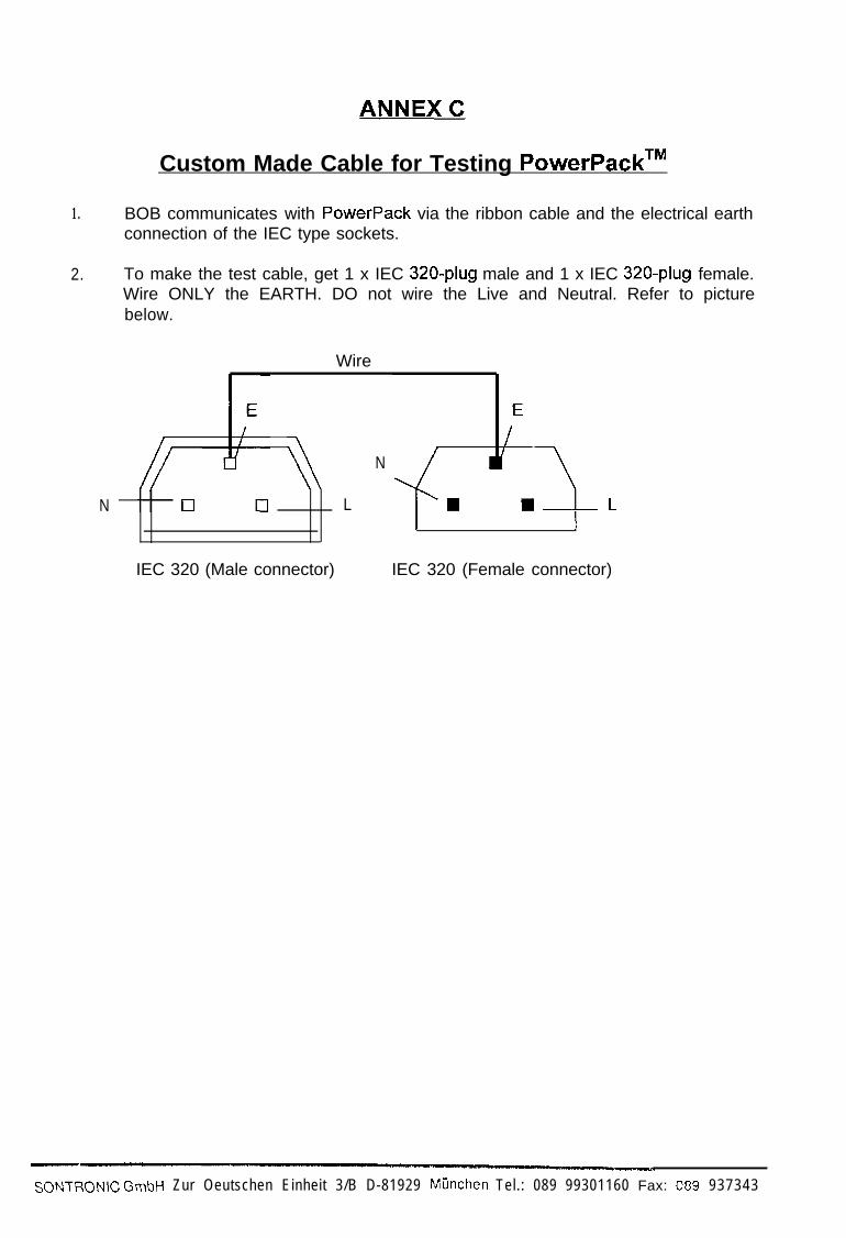
Custom Made Cable for Testing PowerPackTM
1. BOB communicates with PowerPack via the ribbon cable and the electrical earthconnection of the IEC type sockets.
2. To make the test cable, get 1 x IEC 320-plug male and 1 x IEC 320-plug female.Wire ONLY the EARTH. DO not wire the Live and Neutral. Refer to picturebelow.
N
Wire
IEC 320 (Male connector) IEC 320 (Female connector)
N
L
SONTRON\C GmbH Zur Oeutschen Einheit 3/B D-81929 Mijnchen Tel.: 089 99301160 Fax: 089 937343