blenderart_mag-14_eng
DESCRIPTION
Creating Cartoony animation Material Retouching Learning the BGE Issue 14 | Jan 2008 Blender learning made easy - Cristian Mihaescu ‘Hope for a dinner’TRANSCRIPT

Issue 14 | Jan 2008
Blender learning made easy
- Cristian Mihaescu ‘Hope for a dinner’
Making a Low Poly Character
Material Retouching
Creating Cartoony animation
Learning the BGE
Blender Game Networking
Case Study BRE
Gaurav Nawani [email protected]
Sandra Gilbert [email protected]
Nam Pham [email protected]
Gaurav, Sandra, Alex
Kevin BraunPhillip RyalsBruce WestfallJoshua LeungLynda SchemanskyEric PranauskNoah SummersJoshua ScottonMark WarrenWade BickPatrick O'DonnellBrian C. TreacyScott HillHenriel Veldtmann
Brian Cordell HyndsBrian TreacyHusam IbrahimIgor KrianovskijititrxJohn BureshMal DuffinNanmoRogério PerdizTobias Dahl Nielsen
Cristian Mihaescu ‘Hope for a dinner’
CONTENTS
Modeling & Rigging a Cartoon-looking Spider
Making a Low Poly Character from High Poly
Material Retouching using Node & Vertex Color
Creating a Cartoony animation with Blender
Learning the Blender Game Engine
Blender Game Networking
Making of Orion Tear
Making of Tenage Duck
Making of Monkey Game Project
www.blenderart.org Issue 14 | Jan 2008 - Cartoon & GE
2
8
15
19
21
23
43
50
60
65
Case Study Blender Realtime Engine 68
Even after years of using Blender, the wide scope of pos-sibilities for creativity in Blender still amazes me. Youcan create whatever you imagine, from cartoons togames. And in this issue, it is that very diversity that weare going to explore.
Growing up I was always fascinated by cartoons, and tothis day I still enjoy watching cartoons. Especially with allthe advancements in technology paving the way to evermore amazing feats of animation possibilities.
3D modeling programs have changed the look of car-toons and yet the basic concepts developed by the“cartoon masters" remain the same. 3D programs, in-cluding our beloved Blender, allow us the freedom tocreate cartoons in any style that appeals to us. Some-thing that, while possible, was far more difficult usingtraditional "cel" techniques. From the "traditional" look toanime, cartoons are becoming a popular medium of ar-tistic expression.
As 3D animation becomes more popular, the line be-tween cartoon and animation converges and continues toblur, causing the two words to become interchangeable.In fact with the growing number of full length 3D anima-tion movies being produced, the definition of cartoon isexpanding as fast as the imaginative minds of the anima-tors creating them. Decreasing costs of higher pricedmodeling software and free programs like Blender letanyone try their hand at creating their own cartoons andanimations, opening up the cartoon/animation field to anew wave of young cartoon lovers and would be crea-tors.
Building off the growing popularity of cartoons, gamesare quickly becoming an artistic force in their own right.These days, you can find games based on many popularcartoons, animations and movies as well as original con-cepts. In fact “gaming” has become a big industry withgrowing opportunities for those skilled in modeling, tex-turing and yes even character animation. Many game
companies are seriously in need of 3D artists, and I ambetting that need will continue to grow as technologyadvances and the possibility for more graphic intensegames grows. Game creation uses a lot of the same skillsand talents as animation. Knowledge of modeling, textur-ing and character animation is a great help whether youare creating your first game masterpiece or your hun-dredth.
Of special interest to us is the fact that Blender can beused to either create your game assets for exporting to aseparate game engine or you can create games rightwithin Blender itself. The Blender Game Engine has seena great number of improvements over the years, leadingto a growing segment of our community learning to de-velop game assets, demos and full games. As the com-munity grows, solutions are being found, new techniquesare being created and ways to use Blender's logic bricksmore effectively both with and without additional Pythoncoding has led to a growing number of games being cre-ated and released in the GE forums. The variety of gamesbeing created is as imaginative as the artists that havedevoted their time to the GE.
So whether you are an animator, budding game creatoror simply curious about areas of Blender that you haven'tyet learned, we have you covered. We have gathered upsome really great articles to get your creativity up andrunning.
Happy [email protected]
Managing Editor
EDITORIAL 3
www.blenderart.org Issue 14 | Jan 2008 - Cartoon & GE

After recently seeing Virgilio's blog post on compositionand framing, I realized that although I have known aboutthe "Rule of Thirds" for some time, that it was no longersomething I really thought about. Which is a shame, be-cause good composition can make a boring image standout and make you sit up and say 'Wow'!
To a certain extent, a lot of artists use the 'Rule of Thirds'subconsciously when they create their images, whichoddly enough isn't as strange as you would think. Thereare certain proportions and placing of focus points thathumans just instinctively respond to. So quite a few of usjust place objects instinctively and move them arounduntil it 'looks' right.
But like so many things in life, taking a moment to con-sider the impact of composition for your image or anima-tion shots, can create a more dynamic image that fullyengages the viewer.
Realizing that composition was no longer a conscious deci-sion when I sat down to create images, I went back andlooked at some of the images I have done over the years.Not surprisingly, images that I was really pleased withfollowed the 'Rule of Thirds' and images that never quiteseemed to work suffered from bad composition and a totallack of focal point.
I found the exercise extremely enlightening and encourageanyone seeking to improve their images and animations totry it for themselves. When you are done looking at yourown images, try it with other images, remembering to looka variety of images, both good and bad.
If you are not familiar with the 'Rule of Thirds', I suggestyou check out the following two articles. They both havewonderful explanations and visual examples of excellentcompositional practices.
Learning Composition with the New BlueSky Trailer
www.methart.com/tutorials/composition.html
Game Engine Resources, Games and DemosThe Game Engine forum has a number of excellent tutori-als and demos explaining various parts of the Game En-gine, as well as methods to set up a number of differenttypes of games assets such as menus, Computer/enemyAI, shooting projectiles, etc. The forums contain a wealthof information that would be far too lengthy to list here.So I am going to mention just a few that I have seen re-cently that have caught my eye as extremely useful andresourceful uses of GE abilities.
Level Editor Template
Autonomous bots without python
Simple AI
3rd Person Adventure Game Template
Ray sensor shooting tutorial
BGE FPS Template
Official Documentation can be found on the
Blender Wiki :
Game Engine Documentation
BSOD Introduction to the Game Engine
Good composition canmake a boring image
stand out and make yousit up and say 'Wow'!
IZZY SPEAKS : The Importance of Composition 4
www.blenderart.org Issue 14 | Jan 2008 - Cartoon & GE

Sampling of Games and Demos currently in pro-duction More information and updated progress on thesegames/demos can be found by clicking the listed links.
1st MBGP - Kart Racer! : actually a new learningproject that will last one month, at which point anew project will be started.
Project Echo
My First RPG Game (by Rusty246)
Duk! Duk!
GunFlash
My Tetris Game
Shoot'n'score
Good composition canmake a boring image
stand out and make yousit up and say 'Wow'!
IZZY SPEAKS : The Importance of Composition 5
www.blenderart.org Issue 14 | Jan 2008 - Cartoon & GE

Project PeachThe Peach Project is merrily truck-ing along, bringing exciting im-provements and features toBlender. My favorite, of course, isthe new hair/fur capabilities. Ifyou haven't yet seen the resultsof the new hair and fur, you are
surely missing out.
In order to use the same cool new features as the Peachteam, you will need to check out the development SVNrepository, since the needed features have all been addedsince 2.45
New Features Currently in SVNYou can already find some projects in the trunk of SVN.Testing and bug reporting is encouraged. You can readmore about them here.
Skinning Improvements
Rendering Features
Mesh Deform Modifier
Pole Target for IK
Glossy Reflection/Refraction
Raytraced Soft Shadows
QMC Sampling
Weight paint visualization and Multi Modifier
Render Baking and Normal Mapping
Particles and Strands
ProjectApricotProject Apri-cot teammembers willmeet 2ndweek of Janu-ary for a longweekend to prepare for production issues, but the realstart will be the first week of February. Only then will realdecisions be made on game concept, game design, andother targets. However, we do know it’ll be derived fromProject Peach's furry & crazy characters in a forest.
As for the previous open movies, a pre-sale campaign topurchase the DVD set in advance will be organized to al-low the Blender and Crystal Space communities to supportthis project. Again, there’s the ambitious target of reachinga 1000 DVDs sold in advance, before February 1st.
Expect on the DVD the complete game, all content in Crea-tive Commons Attribute, video blog material, clear exam-ples and/or tutorials for how to extend the game, addlevels, change characters, and so on. Early purchasers ofthe Apricot game will get their names credited on thegame intro and final credit roll.
And don’t forget: although we aim at a creating compellinggaming content, the real Apricot target is to improve theopen source pipeline for professional game creation. Thisfocused around Blender as a modeling and animation tool,Crystal Space as 3D engine and delivery platform, andsome Python scripting magic to tie it all together.
Thanks for the support!
-Ton-
BLENDER NEWS
Peac
h, A
pric
ot &
Pre
cisi
on m
odel
ing
6
www.blenderart.org Issue 14 | Jan 2008 - Cartoon & GE

Precision Modeling PDF GuideYou may remember RobertBurke from the excellent tuto-rial (Producing Models WithAccuracy) he wrote in Blend-erArt Magazine’s Issue #11(Mechanical). We are happyto announce and promote hisexpanded work with precisionmodeling in blender. It looksto be an excellent reference that we encourage all blenderusers to check out.
Description from Robert Burke's websiteThe Precision Modeling Guide to Blender is a 151 pagewalk-through of Blender's mesh modeling tools and designtechniques. Illustrated with over 600 images, it gives aclear and concise introduction to using Blender. By pro-gressing through the guide you will be introduced to manyof Blender's commonly used modeling tools and also a fewof the not so well known ones. The tools are presented ina real working design example with explanations of whythe tools are used and not merely a demonstration of thetools in use.
Don't be fooled by the name, the guide is useful to anyonewanting a clear introduction to Blenders mesh modelingtools.
Stats: 151 Pages ; 613 Images; 4.85 Mb
Download the Precision Modeling Guide here.
BLENDER NEWS
Peac
h, A
pric
ot &
Pre
cisi
on m
odel
ing
7
www.blenderart.org Issue 14 | Jan 2008 - Cartoon & GE
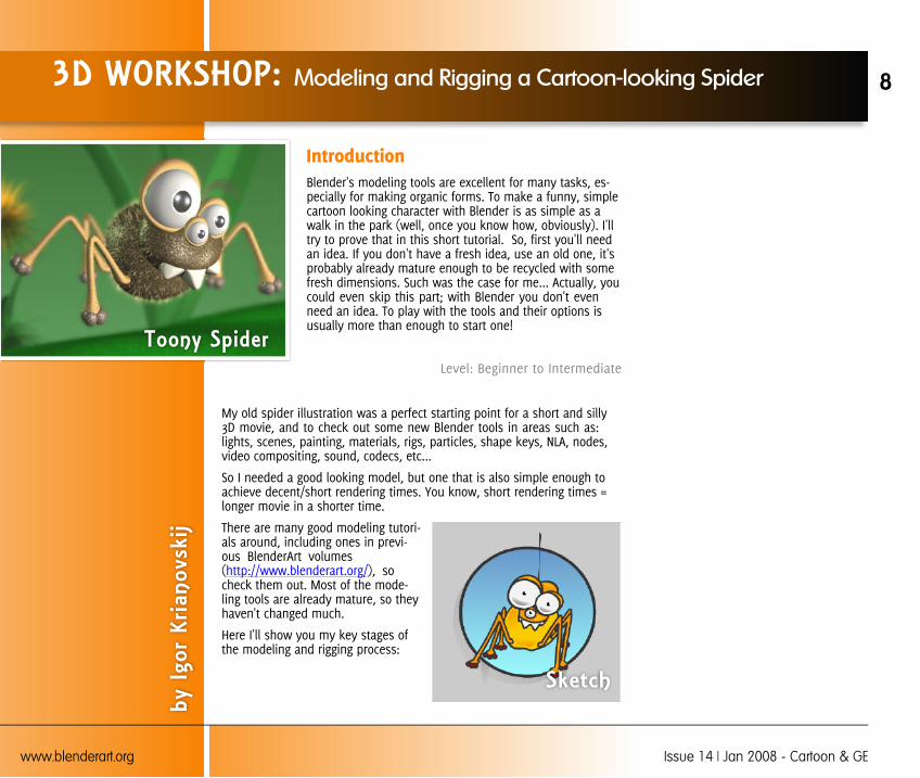
IntroductionBlender's modeling tools are excellent for many tasks, es-pecially for making organic forms. To make a funny, simplecartoon looking character with Blender is as simple as awalk in the park (well, once you know how, obviously). I'lltry to prove that in this short tutorial. So, first you'll needan idea. If you don't have a fresh idea, use an old one, it'sprobably already mature enough to be recycled with somefresh dimensions. Such was the case for me... Actually, youcould even skip this part; with Blender you don't evenneed an idea. To play with the tools and their options isusually more than enough to start one!
Level: Beginner to Intermediate
My old spider illustration was a perfect starting point for a short and silly3D movie, and to check out some new Blender tools in areas such as:lights, scenes, painting, materials, rigs, particles, shape keys, NLA, nodes,video compositing, sound, codecs, etc...
So I needed a good looking model, but one that is also simple enough toachieve decent/short rendering times. You know, short rendering times =longer movie in a shorter time.
There are many good modeling tutori-als around, including ones in previ-ous BlenderArt volumes(http://www.blenderart.org/), socheck them out. Most of the mode-ling tools are already mature, so theyhaven't changed much.
Here I'll show you my key stages ofthe modeling and rigging process:
3D WORKSHOP: Modeling and Rigging a Cartoon-looking Spider
by I
gor
Kria
novs
kij
Sketch
8
www.blenderart.org Issue 14 | Jan 2008 - Cartoon & GE
Toony Spider
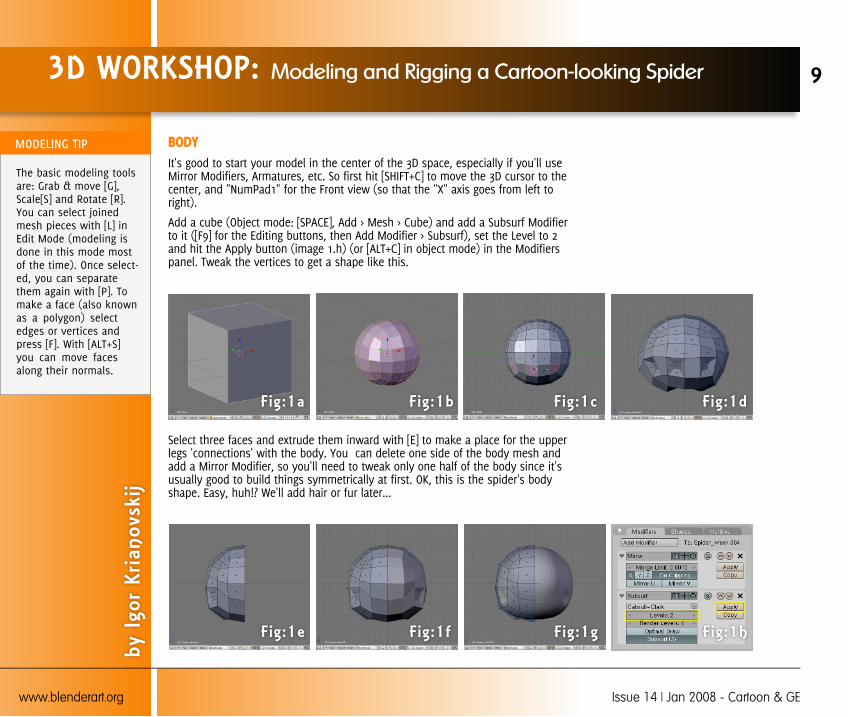
BODYIt's good to start your model in the center of the 3D space, especially if you'll useMirror Modifiers, Armatures, etc. So first hit [SHIFT+C] to move the 3D cursor to thecenter, and "NumPad1" for the Front view (so that the "X" axis goes from left toright).
Add a cube (Object mode: [SPACE], Add > Mesh > Cube) and add a Subsurf Modifierto it ([F9] for the Editing buttons, then Add Modifier > Subsurf), set the Level to 2and hit the Apply button (image 1.h) (or [ALT+C] in object mode) in the Modifierspanel. Tweak the vertices to get a shape like this.
Select three faces and extrude them inward with [E] to make a place for the upperlegs 'connections' with the body. You can delete one side of the body mesh andadd a Mirror Modifier, so you'll need to tweak only one half of the body since it'susually good to build things symmetrically at first. OK, this is the spider's bodyshape. Easy, huh!? We'll add hair or fur later...
3D WORKSHOP: Modeling and Rigging a Cartoon-looking Spider
by I
gor
Kria
novs
kij
Fig:1a Fig:1b
9
www.blenderart.org Issue 14 | Jan 2008 - Cartoon & GE
Fig:1d
The basic modeling toolsare: Grab & move [G],Scale[S] and Rotate [R].You can select joinedmesh pieces with [L] inEdit Mode (modeling isdone in this mode mostof the time). Once select-ed, you can separatethem again with [P]. Tomake a face (also knownas a polygon) selectedges or vertices andpress [F]. With [ALT+S]you can move facesalong their normals.
Fig:1c
Fig:1e Fig:1f Fig:1hFig:1g

HEADCheck the sketch to see how big the head must be to fit the style of the illustra-tion. You can be flexible here, making it bigger or smaller. Sometimes you get bet-ter results when you don't follow the sketch exactly.
There are many ways to build the head for a body. I used the topology of the bodyas the starting point for the head. So, I duplicated body faces (4x3) in Edit Modewith [SHIFT+D]. These 12 new faces are still part of the body mesh, so I separatedthem using [P].
You can make the head in the same way as the body above... from a cube. But byduplicating part of the already existing body mesh you get precise alignment ofvertices which are useful for quicker assembly of body parts (less tweaking, fasterresult!).
So, after a few extrusions [E] and some tweaking of some vertices, I came up withthis:
3D WORKSHOP: Modeling and Rigging a Cartoon-looking Spider
by I
gor
Kria
novs
kij
Fig:2a Fig:2b
10
www.blenderart.org Issue 14 | Jan 2008 - Cartoon & GE
Fig:2dFig:2c
Fig:2e Fig:2f Fig:2hFig:2g
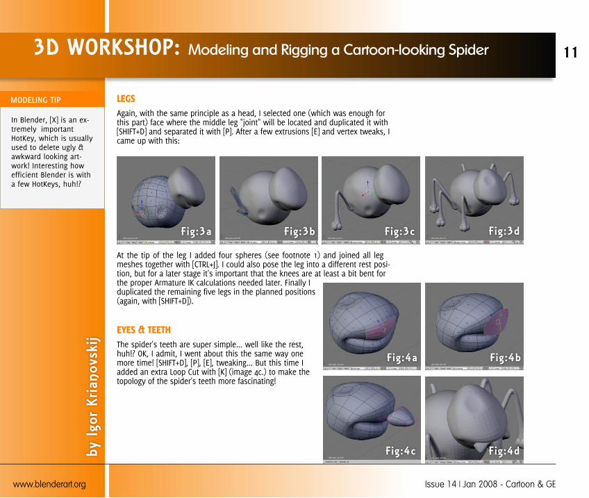
LEGSAgain, with the same principle as a head, I selected one (which was enough forthis part) face where the middle leg "joint" will be located and duplicated it with[SHIFT+D] and separated it with [P]. After a few extrusions [E] and vertex tweaks, Icame up with this:
At the tip of the leg I added four spheres (see footnote 1) and joined all legmeshes together with [CTRL+J]. I could also pose the leg into a different rest posi-tion, but for a later stage it's important that the knees are at least a bit bent forthe proper Armature IK calculations needed later. Finally Iduplicated the remaining five legs in the planned positions(again, with [SHIFT+D]).
EYES & TEETHThe spider's teeth are super simple... well like the rest,huh!? OK, I admit, I went about this the same way onemore time! [SHIFT+D], [P], [E], tweaking... But this time Iadded an extra Loop Cut with [K] (image 4c.) to make thetopology of the spider's teeth more fascinating!
3D WORKSHOP: Modeling and Rigging a Cartoon-looking Spider
by I
gor
Kria
novs
kij
Fig:3a Fig:3b
11
www.blenderart.org Issue 14 | Jan 2008 - Cartoon & GE
Fig:3dFig:3c
Fig:4a Fig:4b
Fig:4dFig:4c
In Blender, [X] is an ex-tremely importantHotKey, which is usuallyused to delete ugly &awkward looking art-work! Interesting howefficient Blender is witha few HotKeys, huh!?
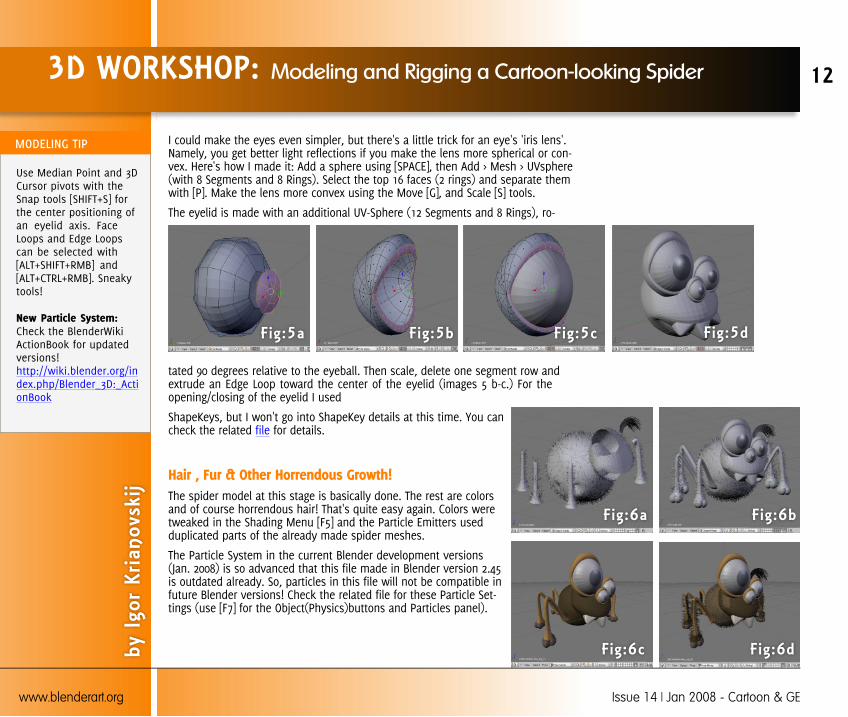
I could make the eyes even simpler, but there's a little trick for an eye's 'iris lens'.Namely, you get better light reflections if you make the lens more spherical or con-vex. Here's how I made it: Add a sphere using [SPACE], then Add > Mesh > UVsphere(with 8 Segments and 8 Rings). Select the top 16 faces (2 rings) and separate themwith [P]. Make the lens more convex using the Move [G], and Scale [S] tools.
The eyelid is made with an additional UV-Sphere (12 Segments and 8 Rings), ro-
tated 90 degrees relative to the eyeball. Then scale, delete one segment row andextrude an Edge Loop toward the center of the eyelid (images 5 b-c.) For theopening/closing of the eyelid I used
ShapeKeys, but I won't go into ShapeKey details at this time. You cancheck the related file for details.
Hair , Fur & Other Horrendous Growth!The spider model at this stage is basically done. The rest are colorsand of course horrendous hair! That's quite easy again. Colors weretweaked in the Shading Menu [F5] and the Particle Emitters usedduplicated parts of the already made spider meshes.
The Particle System in the current Blender development versions(Jan. 2008) is so advanced that this file made in Blender version 2.45is outdated already. So, particles in this file will not be compatible infuture Blender versions! Check the related file for these Particle Set-tings (use [F7] for the Object(Physics)buttons and Particles panel).
3D WORKSHOP: Modeling and Rigging a Cartoon-looking Spider
by I
gor
Kria
novs
kij
Fig:5a Fig:5b
12
www.blenderart.org Issue 14 | Jan 2008 - Cartoon & GE
Fig:5dFig:5c
Fig:6a Fig:6b
Fig:6dFig:6c
Use Median Point and 3DCursor pivots with theSnap tools [SHIFT+S] forthe center positioning ofan eyelid axis. FaceLoops and Edge Loopscan be selected with[ALT+SHIFT+RMB] and[ALT+CTRL+RMB]. Sneakytools!
New Particle System:Check the BlenderWikiActionBook for updatedversions!http://wiki.blender.org/index.php/Blender_3D:_ActionBook

Rig, Oil & Sweat!The next phase toward animation was rigging. This armature contains basic(version 1 - see footnote 2) use of IK constraints, but for an animation I didn't needa more complex rig. So, I added the first bone at the center (Object mode: [SPACE],then Add > Armature). I usually name this first bone Root_'something', in this caseRoot_Spider.
Afterward, I duplicated this bone in Edit Mode, extruded [E] the tips of the bonestwo times and positioned them again with Snapping tools [SHIFT+S].
Here is an example of setting a leg bone in the exact position, which is very hardto achieve by hand, especially when working with organic forms and exotic angles:
Add Bone ; Set pivot to Median Point; select Edges; [SHIFT+S], then chooseCursor -> Selection ; Select the tip of the bone in Edit Mode ; [SHIFT+S], thenchoose Selection -> Cursor
3D WORKSHOP: Modeling and Rigging a Cartoon-looking Spider
by I
gor
Kria
novs
kij
Fig:7a Fig:7b
13
www.blenderart.org Issue 14 | Jan 2008 - Cartoon & GE
Fig:7dFig:7c
If you want to avoidsome unpredictable Ar-mature behavior, start tobuild the rig in thecenter [SHIFT+C]!
If you want to save timein naming bones, nameonly 'important' bones(Root_*, Handle_*, Tag_*)and leave Blender toname the rest of thebones automagically!Only take care to add *.Ror *.L on the end of cer-tain bone names (forexample:Handle_Leg_01.L).Blender will recognizethis as a bone chain onthe Left side. This is alsouseful for Mirror Boneediting!
Fig:8a Fig:8b Fig:8dFig:8c

OK, back to the spider's rig. After I extruded and positioned all needed bones for aleg, I started with an IK chain logic setup. Bones with IK constraint solvers are yel-low colored. Every spider's leg has one IK solver (set to ChainLen:2) which I addedin a Pose Mode (image 9b.). After I duplicated the left/right side legs [SHIFT+D], Ithen added a bone for the head and one bone for a mouth/jaw. There is also anoptional handle for moving all legs simultaneously!
Finally all that was left to do was to attach the mesh to the Armature. That's alsoquite easy. I added an Armature Modifier to the mesh and assigned Vertex Groupsto each bone.
Download the Spider.blend here:
Spider in the park. - Notes1. Adding the spheres this way isn't optimal if you're building the model for agame. There must not be hidden faces in that case! This model was planned for ananimation, so these 'dense' spheres can be used as particle emitters if needed.
2. The Armature system in Blender was build in stages. Version 1 can do FK, IK andsome other basic constraints. Version 2 can do more advanced things (check Man-candy's rig made by Bassam Kurdali as an example). Version 3 is the latest andgreatest Armature system used for characters in the Blender Institute's next "OpenMovie"!
3D WORKSHOP: Modeling and Rigging a Cartoon-looking Spider
by I
gor
Kria
novs
kij
Fig:9a Fig:9b
14
www.blenderart.org Issue 14 | Jan 2008 - Cartoon & GE
Fig:9dFig:9c
You can switch betweenPose and Edit Modeswith [TAB], and Pose andObject Modes with[CTRL+TAB].
Don't forget to disableEnvelopes in the Arma-ture Modifier if you'reusing Vertex Groups!
FINAL MASTER TIP: Oneanimation per day keepsKaito away!
IntroductionThis is a short tutorial explaining a technique to modela low poly Game Engine character over a high polymodel. There are many techniques to accomplish this(box modeling, combing shapes, etc) so this is justone of them. Please use your favourite modeling tech-niques while following along.
Level: Beginner to Intermediate
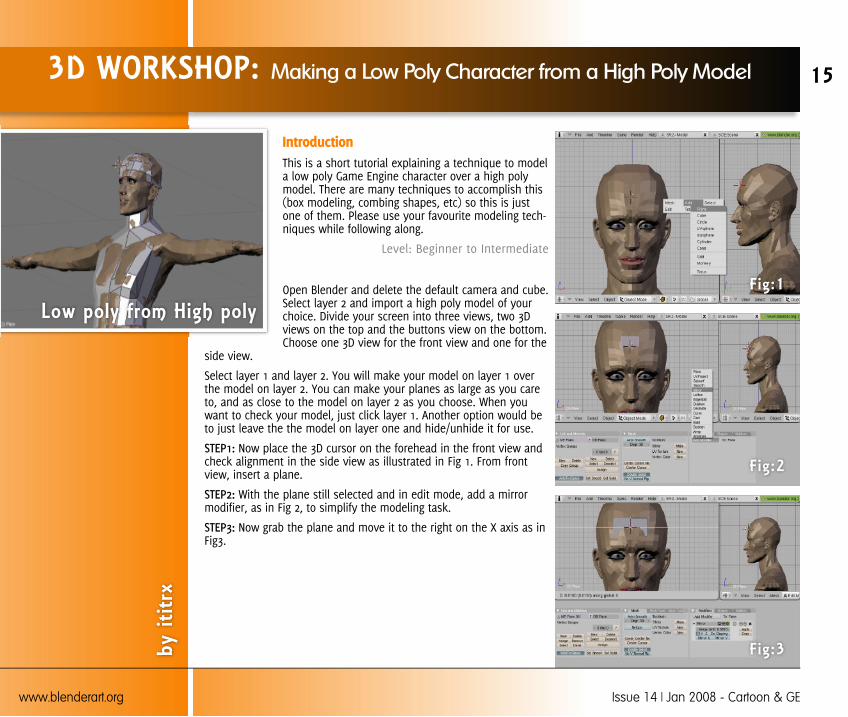
Open Blender and delete the default camera and cube.Select layer 2 and import a high poly model of yourchoice. Divide your screen into three views, two 3Dviews on the top and the buttons view on the bottom.Choose one 3D view for the front view and one for the
side view.
Select layer 1 and layer 2. You will make your model on layer 1 overthe model on layer 2. You can make your planes as large as you careto, and as close to the model on layer 2 as you choose. When youwant to check your model, just click layer 1. Another option would beto just leave the the model on layer one and hide/unhide it for use.
Now place the 3D cursor on the forehead in the front view andcheck alignment in the side view as illustrated in Fig 1. From frontview, insert a plane.
With the plane still selected and in edit mode, add a mirrormodifier, as in Fig 2, to simplify the modeling task.
Now grab the plane and move it to the right on the X axis as inFig3.
3D WORKSHOP: Making a Low Poly Character from a High Poly Model
by i
titrx
Low poly from High poly
15
www.blenderart.org Issue 14 | Jan 2008 - Cartoon & GE
Fig:1
Fig:2
Fig:3
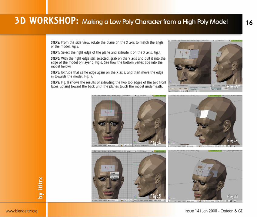
From the side view, rotate the plane on the X axis to match the angleof the model, Fig.4.
Select the right edge of the plane and extrude it on the X axis, Fig.5.
With the right edge still selected, grab on the Y axis and pull it into theedge of the model on layer 2, Fig 6. See how the bottom vertex tips into themodel below?
Extrude that same edge again on the X axis, and then move the edgein towards the model, Fig. 7.
Fig. 8 shows the results of extruding the two top edges of the two frontfaces up and toward the back until the planes touch the model underneath.
3D WORKSHOP: Making a Low Poly Character from a High Poly Model
by i
titrx
16
www.blenderart.org Issue 14 | Jan 2008 - Cartoon & GE
Fig:4
Fig:5
Fig:6
Fig:7
Fig:8

Continue in this manner, covering the model's head on layer 2, Fig 9.
Fig. 10 and Fig.11 illustrate the selection of layer 1 only to modify theexisting planes. Two points were selected and merged into one.
Fig. 12 and Fig. 13 illustrate face creation from the selected vertices tocover/close the gap between the faces.
3D WORKSHOP: Making a Low Poly Character from a High Poly Model
by i
titrx
17
www.blenderart.org Issue 14 | Jan 2008 - Cartoon & GE
Fig:9
Fig:10
Fig:11
Fig:12
Fig:13
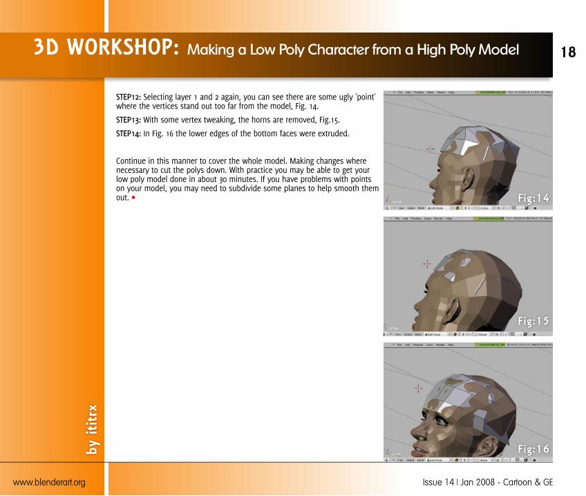
Selecting layer 1 and 2 again, you can see there are some ugly 'point'where the vertices stand out too far from the model, Fig. 14.
With some vertex tweaking, the horns are removed, Fig.15.
In Fig. 16 the lower edges of the bottom faces were extruded.
Continue in this manner to cover the whole model. Making changes wherenecessary to cut the polys down. With practice you may be able to get yourlow poly model done in about 30 minutes. If you have problems with pointson your model, you may need to subdivide some planes to help smooth themout.
3D WORKSHOP: Making a Low Poly Character from a High Poly Model
by i
titrx
18
www.blenderart.org Issue 14 | Jan 2008 - Cartoon & GE
Fig:14
Fig:15
Fig:16
3D WORKSHOP: Material Retouching using Material Node with Vertex Color
byN
anm
o
19
www.blenderart.org Issue 14 | Jan 2008 - Cartoon & GE
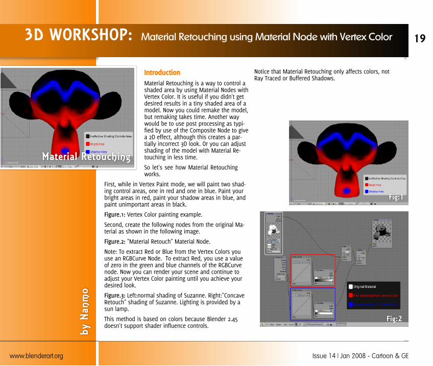
IntroductionMaterial Retouching is a way to control ashaded area by using Material Nodes withVertex Color. It is useful if you didn't getdesired results in a tiny shaded area of amodel. Now you could remake the model,but remaking takes time. Another waywould be to use post processing as typi-fied by use of the Composite Node to givea 2D effect, although this creates a par-tially incorrect 3D look. Or you can adjustshading of the model with Material Re-touching in less time.
So let's see how Material Retouchingworks.
First, while in Vertex Paint mode, we will paint two shad-ing control areas, one in red and one in blue. Paint yourbright areas in red, paint your shadow areas in blue, andpaint unimportant areas in black.
Vertex Color painting example.
Second, create the following nodes from the original Ma-terial as shown in the following image.
"Material Retouch" Material Node.
Note: To extract Red or Blue from the Vertex Colors youuse an RGBCurve Node. To extract Red, you use a valueof zero in the green and blue channels of the RGBCurvenode. Now you can render your scene and continue toadjust your Vertex Color painting until you achieve yourdesired look.
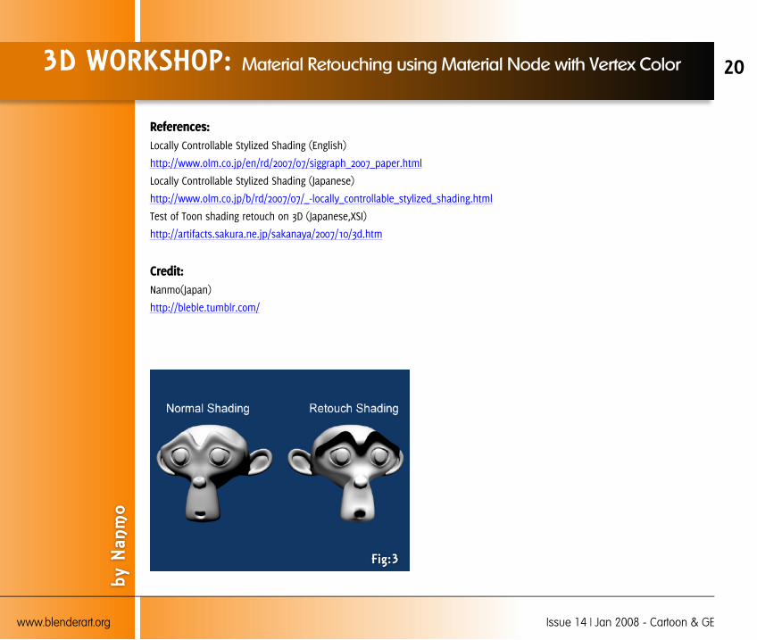
Left:normal shading of Suzanne. Right:"ConcaveRetouch" shading of Suzanne. Lighting is provided by asun lamp.
This method is based on colors because Blender 2.45doesn't support shader influence controls.
Notice that Material Retouching only affects colors, notRay Traced or Buffered Shadows.
Fig:1
Fig:2
Material Retouching
References:Locally Controllable Stylized Shading (English)
http://www.olm.co.jp/en/rd/2007/07/siggraph_2007_paper.html
Locally Controllable Stylized Shading (Japanese)
http://www.olm.co.jp/b/rd/2007/07/_-locally_controllable_stylized_shading.html
Test of Toon shading retouch on 3D (Japanese,XSI)
http://artifacts.sakura.ne.jp/sakanaya/2007/10/3d.htm
Credit:Nanmo(Japan)
http://bleble.tumblr.com/
3D WORKSHOP: Material Retouching using Material Node with Vertex Color
by N
anm
o
20
www.blenderart.org Issue 14 | Jan 2008 - Cartoon & GE
Fig:3

IntroductionThe thing that makes a cartoon fun toread is that they are reality*20. Cartoonsare full of oversized characters that movein oversized ways, and that's what makesthem interesting. Another thing that'simportant when creating cartoons, is mak-ing them easy to read/look at, with clearcolors and sharp shadows. This tutorialwill teach you how to create a little car-toony animation, using those guidelines.Happy cartooning!
Part One (Animation setup andAnimation)NOTE: if you just want to apply the cartoon effect to a sceneyou've already created, you can skip to Part Two.
The reason I've put 'animation setup' instead of 'modeling'or 'rigging' is that, to keep it simple, we'll be animating asimple sphere, though the principles of animating thissphere can be used whatever you are animating. Start bydeleting the default cube and go to top view. Create a UV-Sphere and go to the Edit tab and select 'Set Smooth'. Thengo to Front View and put the sphere just above the redline(the x-axis).
We will use the red line as a guideline, to show where thefloor is, when we are in front view. Create a cube, scale itdown a lot, and put it on top of the sphere. The cube willbe our 'rig'. Select the sphere, and go to the 'Object' taband click 'Add Constraint' and then 'Stretch To'. Write 'Cube'in the 'Target' field. Try moving the cube.
The sphere should now stretch towards the cube, whilemaintaining its volume (if you move the cube far away, thesphere will get thin, etc.). Go to top view and create aplane. Move it around so that it's just below the sphere. Go
to camera view and scale it up until just before it exceedsthe clipping. Split the 3D view near the top, and changethe new area to a timeline.
Select the camera and press [ALT-R]. Rotate the camera 90degrees by the x axis, and move it , so that it's just in frontof the sphere. Go to frame 0, and click the red circle buttonin the Timeline area (this will 'record' the places you putthe ball). Go to camera view, select both the sphere andthe cube, and move them, by the x axis, to a place justoutside the camera's border.
Move them both up a little. Nowwe're ready to go! Move the ball upand down for every tenth frame, likeshown in the picture (the first ballbeing frame 0, the next frame 10,and so on), and use the cube to'smash' the ball when it hits theground, by moving it towards theball.
Remember to move both the ball and the cube! In theframes in between (5,15,25 and so on) stretch the ball, sothat one end is pointing at the previous key-pose, and theother is pointing at the next, like shown in the picture.That's actually thebasic principles ofsquash and stretch!Objects that move,stretch; objects thatcollide with some-thing, squash.
NOTE: Don't expect perfect results the first time you try this! Itmay take some practice to get good at it!
3D WORKSHOP: Creating a Cartoony animation with Blender
by T
obia
s D
ahl N
iels
en
21
www.blenderart.org Issue 14 | Jan 2008 - Cartoon & GE
Cartoony Animation

Part Two (Materials, Lighting and Node Setup)Firstly, go to the Scene tab, and click the 'Edge' button. Thenclick 'Render Layers' and select 'Col' and 'Sha'. Those are the'Color' and 'Shadow' passes (we'll need them for the nodesetup). Secondly, click the button below the word 'Scene:', andselect 'ADD NEW'. This will create a new RenderLayer. Thendisable the buttons: 'Solid', 'Halo', 'Ztra' and 'Sky'. We will needthat for using 'Edge' in the node setup.
Materials: Thematerials shouldsimply be clearcolored, and with-out specularity (ifyou can do with-out it). I havechosen a clear redcolor for thesphere. Also,avoid 'Ray-Mirror', as it just doesn't mix with the cartoonstyle. The cube should have a completely transparent materi-al, which shouldn't be traceable or specular.
Lighting: The lighting should consist of a single sun lamp,'shining' from the top right of the image. NOTE: This is just forthis specific project. You can use any lighting setup you want to.
Nodes: As I mentioned before, we're going to have a sepa-rate RenderLayer for the toon edge. This is actually a worka-round for a Node problem I ran into, which wouldn't show theedge in some parts of the image (the ones that were in frontof the ground, to be exact). This is the complete node setup:
It consists of two RenderLayers (the default one, and the onewe created). We 'add' the color and shadow passes from thefirst RenderLayer, creating the cartoony shading ('Fac' shouldbe around 0.35). Then we 'mix' the output from that, and theimage (with alpha) to get the sky displayed too ('Fac' around
0.74). At last we mix the output from that, with the imagefrom the second layer (with alpha) creating the toon edge
('Fac' around 1). You can play around with the fac settings toget just the effect you want, however, I found that thisworked best for me. Make sure that you connected the differ-ent Node's the same way I did. Now all you have to do is toselect 'AVI Raw' (or whatever movie format you like) under'Format', and click 'Anim'. That's it! Your cartoon animation iscomplete!
You can watch an extended version of the animation made inthis tutorial here.
If you have any trouble or comments, please email me at:[email protected]
3D WORKSHOP: Creating a Cartoony animation with Blender
By T
obia
s D
ahl N
iels
en
22
www.blenderart.org Issue 14 | Jan 2008 - Cartoon & GE
IntroductionThis tutorial will show the reader how tocreate a simple 3D game from scratch inBlender. After completing the tutorial, theskills learned will allow readers to extendthe game levels. It assumes a basicknowledge of Blender, but not of thebuilt-in Game Engine (GE). Only aspects ofBlender that are relevant to making sim-ple games will be touched on.
The tutorial should take around 2 hours tocreate a working 3D game from scratch.
Level: Beginner to Intermediate
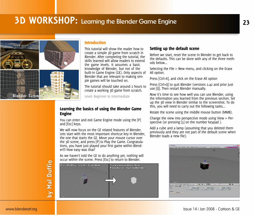
Learning the basics of using the Blender GameEngineYou can enter and exit Game Engine mode using the [P]and [Esc] keys.
We will now focus on the GE related features of Blender.Lets start with the most important shortcut key in Blender,the one that starts the GE. Move your mouse cursor overthe 3D scene, and press [P] to Play the Game. Congratula-tions, you have just played your first game within Blend-er!!! How easy was that?
As we haven't told the GE to do anything yet, nothing willoccur within the scene. Press [Esc] to return to Blender.
Setting up the default sceneBefore we start, reset the scene in Blender to get back tothe defaults. This can be done with any of the three meth-ods below...
Selecting the File >> New menu, and clicking on the EraseAll option.
Press [Ctrl+X], and click on the Erase All option
Press [Ctrl+Q] to quit Blender (versions 2.42 and prior justuse [Q]. Then restart Blender manually.
Now it's time to see how well you can use Blender, usingthe information you learned from the previous section. Setup the 3D view in Blender similar to the screenshot. To dothis, you will need to carry out the following tasks...
Rotate the scene using the middle mouse button (MMB).
Change the view into perspective mode using View >> Per-spective (or pressing [5] on the number keypad ).
Add a cube and a lamp (assuming that you deleted thempreviously and they are not part of the default scene whenBlender loads a new file).
3D WORKSHOP: Learning the Blender Game Engine
by M
al D
uffin
23
www.blenderart.org Issue 14 | Jan 2008 - Cartoon & GE
Blender Summer of Documentat ion
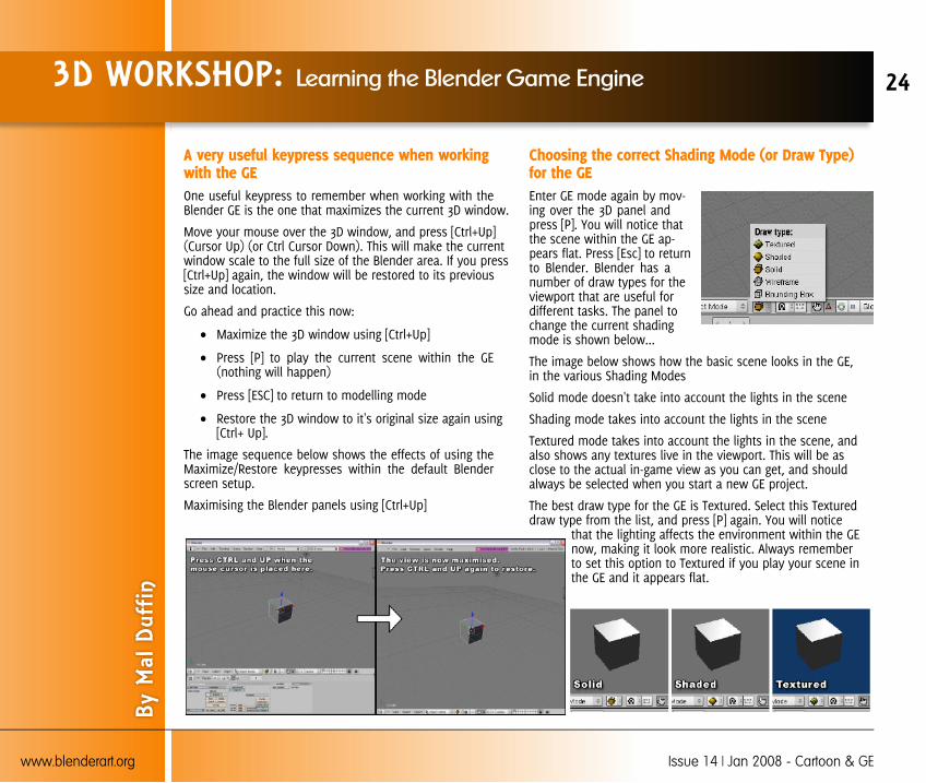
A very useful keypress sequence when workingwith the GEOne useful keypress to remember when working with theBlender GE is the one that maximizes the current 3D window.
Move your mouse over the 3D window, and press [Ctrl+Up](Cursor Up) (or Ctrl Cursor Down). This will make the currentwindow scale to the full size of the Blender area. If you press[Ctrl+Up] again, the window will be restored to its previoussize and location.
Go ahead and practice this now:
Maximize the 3D window using [Ctrl+Up]
Press [P] to play the current scene within the GE(nothing will happen)
Press [ESC] to return to modelling mode
Restore the 3D window to it's original size again using[Ctrl+ Up].
The image sequence below shows the effects of using theMaximize/Restore keypresses within the default Blenderscreen setup.
Maximising the Blender panels using [Ctrl+Up]
Choosing the correct Shading Mode (or Draw Type)for the GEEnter GE mode again by mov-ing over the 3D panel andpress [P]. You will notice thatthe scene within the GE ap-pears flat. Press [Esc] to returnto Blender. Blender has anumber of draw types for theviewport that are useful fordifferent tasks. The panel tochange the current shadingmode is shown below...
The image below shows how the basic scene looks in the GE,in the various Shading Modes
Solid mode doesn't take into account the lights in the scene
Shading mode takes into account the lights in the scene
Textured mode takes into account the lights in the scene, andalso shows any textures live in the viewport. This will be asclose to the actual in-game view as you can get, and shouldalways be selected when you start a new GE project.
The best draw type for the GE is Textured. Select this Textureddraw type from the list, and press [P] again. You will notice
that the lighting affects the environment within the GEnow, making it look more realistic. Always rememberto set this option to Textured if you play your scene inthe GE and it appears flat.
3D WORKSHOP: Learning the Blender Game Engine
By M
al D
uffin
24
www.blenderart.org Issue 14 | Jan 2008 - Cartoon & GE

The Main Game Logic PanelBelow the 3D window, you will see the panel that containsmany different buttons for controlling different aspects ofBlender.
You can view the panel related to the GE by clicking on thepurple Pacman-like icon , just like below or by pressing [F4].
This panel is where you will control what will happen withinyour game.
Blender uses a visual click-and-drag system to create basicgame interactions. This allows the GE to be used by 3D artistswho may not have access to a coder. Blender also has a pro-gramming language, Python, which can be used to createmore complex game interactions.
For the purposes of this tutorial, we will focus on the visualsystem for creating games. When you have grasped the basicsof using the Blender GE, you can then follow more advancedtutorials showing how to implement Python scripting to createmore complex games.
Visually controlling the GE - Sensors, Actuators,Controller Logic BlocksThe GE system uses Logic Blocks as a visual way to set upinteractions within the game. These logic blocks can be con-nected together visually to allow for complex game actions totake place.
There are three different types of Logic Blocks - Sensors, Con-trollers and Actuators - each with a number of different sub-types.
SensorsA Sensor will detect some form of input. This input could beanything from a keypress, a joystick button or a timer thattriggers every single screen update (or frame) of the game.
ControllersControllers are used to link Sensors to Actuators. They allowfor some more complex control over how sensor and actuatorsinteract with each other.
ActuatorsAn Actuator will actually carry out an action within the game.This can include moving an object within a scene, playing ananimation, or playing a sound effect.
3D WORKSHOP: Learning the Blender Game Engine
By M
al D
uffin
25
www.blenderart.org Issue 14 | Jan 2008 - Cartoon & GE

Setting up a basic Sensor, Controller, Actuator LogicBlock sequence.We will now set up a very basic system within the game panelby adding and connecting a sensor, controller and actuatortogether.
GE Panel: Make sure the Game Logic panel is visible (click onthe purple pacman in the Buttons window or press [F4]), andre-select the cube within the 3D scene
Below each of the 3 main sections, you will see the selectedobject's name, and an Add button. Click this Add button oncefor each of the 3 sections: Sensor, Controller and Actuator.
We will now connect this system together. Click and drag fromthe socket (small circle) at the end of the first sensor to thesocket at the start of the controller. Then click and drag fromthe socket at the end of the controller to the socket at thestart of the actuator.
The image sequence on right shows the steps involved in set-ting up a simple Sensor, Controller, Actuator chain and con-necting them together.
Press [P] to now play the game. You will notice that, althoughwe have added some control to the GE, nothing seems to hap-pen again. This will be explained in the next section. Press[Esc] to return to Blender.
Breaking down the events in the GE systemWe will now look into what is happening with our newly cre-ated GE system. The sensor is an Always timer. This will sendout a signal every single frame keeping the linked controllercontinuously activated thoughout the duration of the game.
The controller is an AND. When it has just one active sensorinput (like in the current case), it will automatically call theconnected Actuator.
The Actuator controls the Motion aspects of the selected ob-ject. Because of the Always sensor connected to the controller,this actuator will be called every single frame.
If we press [P] now, the Motion actuator is being called everysingle frame, but because all of its values are set to zero, itwill not move the object within the GE. Press [Esc] again toreturn to Blender.
3D WORKSHOP: Learning the Blender Game Engine
By M
al D
uffin
26
www.blenderart.org Issue 14 | Jan 2008 - Cartoon & GE
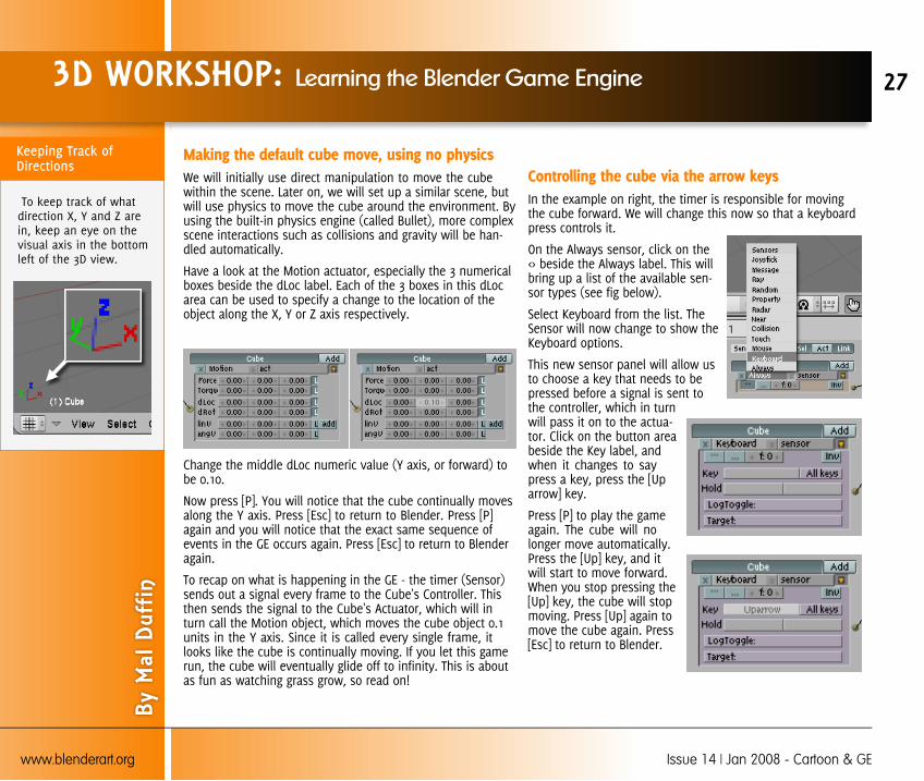
Making the default cube move, using no physicsWe will initially use direct manipulation to move the cubewithin the scene. Later on, we will set up a similar scene, butwill use physics to move the cube around the environment. Byusing the built-in physics engine (called Bullet), more complexscene interactions such as collisions and gravity will be han-dled automatically.
Have a look at the Motion actuator, especially the 3 numericalboxes beside the dLoc label. Each of the 3 boxes in this dLocarea can be used to specify a change to the location of theobject along the X, Y or Z axis respectively.
Change the middle dLoc numeric value (Y axis, or forward) tobe 0.10.
Now press [P]. You will notice that the cube continually movesalong the Y axis. Press [Esc] to return to Blender. Press [P]again and you will notice that the exact same sequence ofevents in the GE occurs again. Press [Esc] to return to Blenderagain.
To recap on what is happening in the GE - the timer (Sensor)sends out a signal every frame to the Cube's Controller. Thisthen sends the signal to the Cube's Actuator, which will inturn call the Motion object, which moves the cube object 0.1units in the Y axis. Since it is called every single frame, itlooks like the cube is continually moving. If you let this gamerun, the cube will eventually glide off to infinity. This is aboutas fun as watching grass grow, so read on!
Controlling the cube via the arrow keysIn the example on right, the timer is responsible for movingthe cube forward. We will change this now so that a keyboardpress controls it.
On the Always sensor, click on the<> beside the Always label. This willbring up a list of the available sen-sor types (see fig below).
Select Keyboard from the list. TheSensor will now change to show theKeyboard options.
This new sensor panel will allow usto choose a key that needs to bepressed before a signal is sent tothe controller, which in turnwill pass it on to the actua-tor. Click on the button areabeside the Key label, andwhen it changes to saypress a key, press the [Uparrow] key.
Press [P] to play the gameagain. The cube will nolonger move automatically.Press the [Up] key, and itwill start to move forward.When you stop pressing the[Up] key, the cube will stopmoving. Press [Up] again tomove the cube again. Press[Esc] to return to Blender.
3D WORKSHOP: Learning the Blender Game Engine
By M
al D
uffin
27
www.blenderart.org Issue 14 | Jan 2008 - Cartoon & GE
To keep track of whatdirection X, Y and Z arein, keep an eye on thevisual axis in the bottomleft of the 3D view.

Adding in additional keyboard controlsWe will now add in the ability to move the cube backwards, aswell as rotating it, to allow you to move it around the 3D envi-ronment.
To add the ability to move backwards, we will add in a new(but nearly identical) set of GE logic bricks. Click the Add but-ton again on the Sensor, Controller and Actuator areas, to cre-ate 3 new logic bricks on the GE panel. Connect these asbefore.
NOTE - You might want to use the [Ctrl+Up] key to maximiseand restore the game logic panel when working in it, as it willbecome cluttered very quickly.
With the newly added sensor, change it to keyboard type, andset it to use the [Down] arrow key. In the newly added Motionactuator, change the Y value (2nd column) of the dLoc area tobe -0.1.
Press [P] to play the game. If the logic blocks are set up cor-rectly, you should now be able to move the cube forward and
backward just by using the [Up] and [Down] arrow keys.
To complete this "no physics" part of the tutorial, we will addin the ability to rotate the object as well, so that you will beable to "drive" your model around the 3D environment.
Add in 3 new logic blocks as before, connect them, andchange the sensor type to keyboard. Set the keyboard entry touse the [Left] arrow key.
Now, in the Motion Actuator, we will set it to rotate the cube.To do this, we will rotate the object around its Z axis. In thedRot area, change the Z value (3rd column) to be -0.1.
Press [P] to play the game. When you click the [Left] key, thecube will rotate. When you press the [Up] arrow key, the cubewill move forward in that direction. Press [Esc] to return toBlender, and we will add in the ability to rotate the other way.
As before, add in 3 new logic blocks, connect them, andchange the sensor type to keyboard.
Set the keyboard entry to use the [Right] arrow key, and the Zvalue (3rd column) in the dRot section in the Motion actuatorto be 0.1.
Press [P] again to run the game. You can now "drive" the cubearound the 3D environment using the arrow keys. Note thatyou can add this game logic to any model in Blender (no mat-ter what shape or size it is), and it will move around just likethe cube. Press [Esc] to return to Blender.
3D WORKSHOP: Learning the Blender Game Engine
By M
al D
uffin
28
www.blenderart.org Issue 14 | Jan 2008 - Cartoon & GE
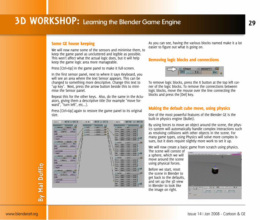
Some GE house keepingWe will now name some of the sensors and minimise them, tokeep the game panel as uncluttered and legible as possible.This won't affect what the actual logic does, but it will helpkeep the game logic area more manageable.
Press [Ctrl+Up] in the game panel to make it full-screen.
In the first sensor panel, next to where it says Keyboard, youwill see an area where the text Sensor appears. This can bechanged to something more descriptive. Change this text to"up key". Next, press the arrow button beside this to mini-mise the Sensor panel.
Repeat this for the other keys. Also, do the same in the Actu-ators, giving them a descriptive title (for example "move for-ward", "turn left", etc...).
Press [Ctrl+Up] again to restore the game panel to its originalsize.
As you can see, having the various blocks named make it a loteasier to figure out what is going on.
Removing logic blocks and connections
To remove logic blocks, press the X button at the top left cor-ner of the logic blocks. To remove the connections betweenlogic blocks, move the mouse over the line connecting theblocks and press the [Del] key.
Making the default cube move, using physicsOne of the most powerful features of the Blender GE is thebuilt-in physics engine (Bullet).
By using forces to move an object around the scene, the phys-ics system will automatically handle complex interactions suchas resolving collisions with other objects in the scene. Formany game types, using Physics will solve more complex is-sues, but it does require slightly more work to set it up.
We will now create a basic game from scratch using physics.The scene will consist ofa sphere, which we willmove around the sceneusing physical forces.
Before we start, resetthe scene in Blender toget back to the defaults,and set up the 3D viewin Blender to look likethe image on right.
3D WORKSHOP: Learning the Blender Game Engine
By M
al D
uffin
29
www.blenderart.org Issue 14 | Jan 2008 - Cartoon & GE
Set up Blender to look like this for the following tutorial
Select the File >> New menu, and click on the Erase Alloption.
Rotate the scene using the middle mouse button MMB
Change the view into perspective mode using View >>Perspective (or Keypad [5])
Change the 3D view to use the Textured shading mode(/Draw Type) or press [Alt+Z]
Open the Game (/Logic) panel
Setting up the game scene To start creating the game scene,delete the cube by pressing [Del].
Add in a sphere using Add >> Mesh >> UVSphere(pressing the[spacebar] alsobrings up thismenu).
When asked, selectthe default 32 seg-ments and 32 ringsas the setup of thesphere.
Exit Edit modestraight away onthe sphere bypressing [Tab], toreturn to Object mode.
Also, press [Alt+R] to clear the rotation on the object(The object must still be selected).
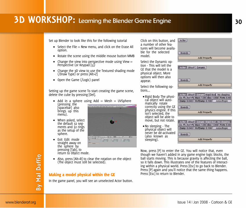
Making a model physical within the GEIn the game panel, you will see an unselected Actor button.
Click on this button, anda number of other fea-tures will become availa-ble for the selectedmodel.
Select the Dynamic op-tion - This will tell theGE that the model is aphysical object. Moreoptions will then alsoappear.
Select the following op-tions...
Rigid Body The physi-cal object will auto-matically rotatecorrectly using the GEphysics engine. If thisisn't selected, theobject will be able tomove, but not rotate.
No sleeping - Thephysical object willnever be de-activated(also known assleeping).
Now, press [P] to enter the GE. You will notice that, eventhough we haven't added in any game engine logic blocks, theball starts moving. This is because gravity is affecting the ball,so it falls down. This illustrates one of the features of interact-ing within a physical world. Press [Esc] to go back to Blender.Press [P] again and you'll notice that the same thing happens.Press [Esc] to return to Blender.
3D WORKSHOP: Learning the Blender Game Engine
By M
al D
uffin
30
www.blenderart.org Issue 14 | Jan 2008 - Cartoon & GE

We need to add something for theball to fall onto, for example aground object.
Add a plane model to thescene using Add >> Mesh >>Plane.
Press [Tab] to exit Edit Objectmode, and return to Objectmode.
Press [Alt+R] to reset the rota-tion on the model.
Use the 3D Transform Manipulator tomove the plane underneath thesphere, and press [P]. You will noticethat the physical sphere now fallsdue to gravity, but will land on theplane below it and come to a rest.
We will now scale the plane up [S], sothat we have plenty of room to movethe ball around within.
Change the 3D transform manipulatorfrom move mode into scale mode.
Grab the scaling handles and size theplane so that it is around 10 timeslarger in the X and Y directions.
The image sequence on right illus-trates the sequence of steps indi-cated above.
3D WORKSHOP: Learning the Blender Game Engine
By M
al D
uffin
31
www.blenderart.org Issue 14 | Jan 2008 - Cartoon & GE
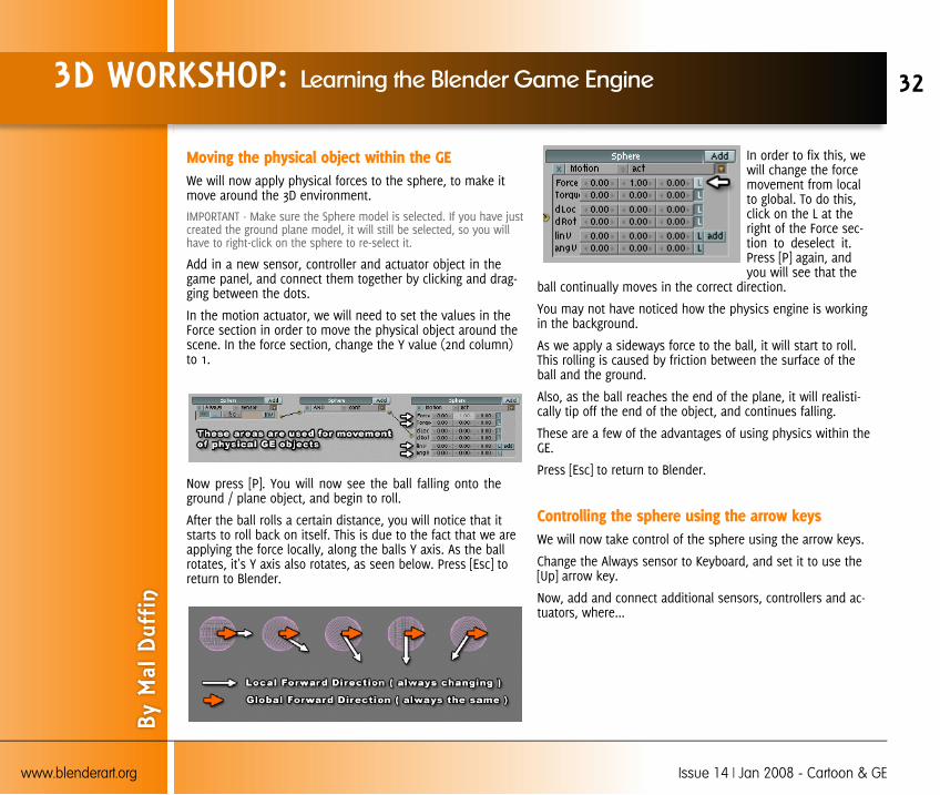
Moving the physical object within the GEWe will now apply physical forces to the sphere, to make itmove around the 3D environment.
IMPORTANT - Make sure the Sphere model is selected. If you have justcreated the ground plane model, it will still be selected, so you willhave to right-click on the sphere to re-select it.
Add in a new sensor, controller and actuator object in thegame panel, and connect them together by clicking and drag-ging between the dots.
In the motion actuator, we will need to set the values in theForce section in order to move the physical object around thescene. In the force section, change the Y value (2nd column)to 1.
Now press [P]. You will now see the ball falling onto theground / plane object, and begin to roll.
After the ball rolls a certain distance, you will notice that itstarts to roll back on itself. This is due to the fact that we areapplying the force locally, along the balls Y axis. As the ballrotates, it's Y axis also rotates, as seen below. Press [Esc] toreturn to Blender.
In order to fix this, wewill change the forcemovement from localto global. To do this,click on the L at theright of the Force sec-tion to deselect it.Press [P] again, andyou will see that the
ball continually moves in the correct direction.
You may not have noticed how the physics engine is workingin the background.
As we apply a sideways force to the ball, it will start to roll.This rolling is caused by friction between the surface of theball and the ground.
Also, as the ball reaches the end of the plane, it will realisti-cally tip off the end of the object, and continues falling.
These are a few of the advantages of using physics within theGE.
Press [Esc] to return to Blender.
Controlling the sphere using the arrow keysWe will now take control of the sphere using the arrow keys.
Change the Always sensor to Keyboard, and set it to use the[Up] arrow key.
Now, add and connect additional sensors, controllers and ac-tuators, where...
3D WORKSHOP: Learning the Blender Game Engine
By M
al D
uffin
32
www.blenderart.org Issue 14 | Jan 2008 - Cartoon & GE

We will now apply physical forces to the sphere, to make itmove around the 3D environment.
IMPORTANT - Make sure the Sphere model is selected. If you have justcreated the ground plane model, it will still be selected, so you willhave to right-click on the sphere to re-select it.
Add in a new sensor, controller and actuator object in thegame panel, and connect them together by clicking and drag-ging between the dots.
In the motion actuator, we will need to set the values in theForce section in order to move the physical object around thescene. In the force section, change the Y value (2nd column)to 1.
Now press [P]. You will now see the ball falling onto theground / plane object, and begin to roll.
After the ball rolls a certain distance, you will notice that itstarts to roll back on itself. This is due to the fact that we areapplying the force locally, along the balls Y axis. As the ballrotates, it's Y axis also rotates, as seen below. Press [Esc] toreturn to Blender.
In order to fix this, we will change the force movement fromlocal to global. To do this, click on the L at the right of theForce section to deselect it. Press [P] again, and you will seethat the ball continually moves in the correct direction.
You may not have noticed how the physics engine is workingin the background.
As we apply a sideways force to the ball, it will start to roll.This rolling is caused by friction between the surface of theball and the ground.
Also, as the ball reaches the end of the plane, it will realisti-cally tip off the end of the object, and continues falling.
These are a few of the advantages of using physics within theGE. Press [Esc] to return to Blender.
Controlling the sphere using the arrow keysWe will now take control of the sphere using the arrow keys.
Change the Always sensor to Keyboard, and set it to use the[Up] arrow key. Now, add and connect additional sensors, con-trollers and actuators, where...
The [Down] keyboard sensor controls the motion actua-tor with a -1 in the Y (2nd) location of the Force section(with L for Local de-selected.)
The [Left] keyboard sensor controls the motion actuatorwith a -1 in the X (1st) location of the Force section(with L for Local de-selected.)
The [Right] keyboard sensor controls the motion actua-tor with a 1 in the X (1st) location of the Force section(with L for Local de-selected.)
3D WORKSHOP: Learning the Blender Game Engine
By M
al D
uffin
33
www.blenderart.org Issue 14 | Jan 2008 - Cartoon & GE

When you press [P] again, you will be able to control the balland move it around the ground plane. Press [Esc] to return toBlender.
To make the game panel screen more legible, give the varioussensors and actuators suitable labels, such as "up key" for thefirst sensor, and "push up" to the first actuator.
Also, try changing the values in all of the motion actuatorsfrom 1 to 2, and from -1 to -2. Press [P] now, and you will seethe difference in the speed of the ball when using the arrowkeys.
Adding some obstacles into the levelAdd a cube to the environment, using Add >> Mesh >> Cube.Press [Tab] to exit Edit mode and return to Object model. Press[Alt+R] to clear the rotation on the object, and drag the arrowsof the 3D transform manipulator to place the box somewhereon the surface of the plane object. Repeat this step to add a
few more objects to the surface of the plane, including cylin-der and monkey objects.
Now, press [P]. You will see that the ball will automaticallycollide and bounce off the objects that you just added. Again,this is one of the advantages of using physics within the GE.Press [Esc] to return to Blender. You might want to try addingin planes and scaling them to make ramps and jumps.
If you have experience with editing models in Blender, youcan spend some time now creating a more complex level lay-out. If you don't have experience modelling in Blender, hope-fully this tutorial will have given you an interest in Blenderand learning more, including how to edit models. You can seesome links to tutorials on editing at the end of this tutorial.
Making some of the objects physicalSelect the cube that you have added into the new scene. Inthe Game Panel, select the following options, the same onesthat were set for the main sphere (except that No Sleeping isnot selected this time, to allow the objects to settle and rest /sleep - when an object is sleeping, it takes less time to com-pute within the physics system)
Actor
Dynamic
Rigid Body
Now, press [P] to play the game, and move the main sphereinto the cube. You will see that the cube now gets knockedout of the way.
However, the box moves in a very odd way - it actually movesas if it was a sphere.
3D WORKSHOP: Learning the Blender Game Engine
By M
al D
uffin
34
www.blenderart.org Issue 14 | Jan 2008 - Cartoon & GE

Currently the physics system will assume that a newly addedrigid body will have a spherical collision shape. Press [Esc] toreturn to Blender.
You will notice that there is a Bounds button below the Actorarea. Click this button, and an additional dropdown will ap-pear, with the default setting of Box.
In the case of the cube, a Box collision type will work fine.However if you have a more complex shape, you will want toselect the Convex Hull Polytope option.
Select some of the other objects you have added to the scene,and carry out the same steps as above, selecting Convex HullPolytope as the bounds type of the object.
Press [P] again to play the current level, and roll into the vari-ous physical objects to move them out of the way. Press [Esc]to return to Blender.
Renaming objectsWhen you add a new object, Blender will assign it a defaultname (e.g. Cube, or Cube.001 if Cube already exists).
It is good practice to rename your objects using more relevantterms, such as player, crate, pickup, etc... This will make yourscene easier to understand when it gets more complex, as
well as keeping it understandable for other people viewing it.To rename an object, you can select the Object panel, andchange the name within the OB: area.
You can also rename the object within the Editing panel.
Completion of the basic GE tutorialCongratulations on completing the basic Blender Game Enginetutorial! You should now have a general overview of the basicsof using the GE. You will have practical experience of...
Connecting sensors, controllers and actuators in thegame panel
Using the motion actuator to move objects directly
Using the motion actuator to move objects using physi-cal forces
Taking keyboard control of game objects
Creating a simple 3D game scene
Making new objects physical within the GE
3D WORKSHOP: Learning the Blender Game Engine
By M
al D
uffin
35
www.blenderart.org Issue 14 | Jan 2008 - Cartoon & GE
With the skills you have learned so far, you will be able toextend this simple environment as you learn more aboutmodelling within Blender.
At this stage, you might want to recreate the final scene again,starting from scratch, to see how far you can get without read-ing the instructions. If you can recreate it all from memory,you are on your way to becoming a true Blender GE poweruser!
The next few additional areas below will cover some morecomplex issues, such as making the ball jump, and addingmaterials to the scene.
Creating more complex game levels and interac-tions :
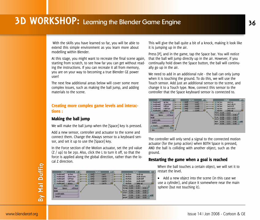
Making the ball jumpWe will make the ball jump when the [Space] key is pressed.
Add a new sensor, controller and actuator to the scene andconnect them. Change the Always sensor to a keyboard sen-sor, and set it up to use the [Space] key.
In the Force section of the Motion actuator, set the 3rd value(Z / up) to be 250. Also, click the L to turn it off, so that theforce is applied along the global direction, rather than the lo-cal Z direction.
This will give the ball quite a bit of a knock, making it look likeit is jumping up in the air.
Press [P], and in the game, tap the Space bar. You will noticethat the ball will jump directly up in the air. However, if youcontinually hold down the Space button, the ball will continu-ally go up in the air.
We need to add in an additional rule - the ball can only jumpwhen it is touching the ground. To do this, we will use theTouch sensor. Add just an additional sensor to the scene, andchange it to a Touch type. Now, connect this sensor to thecontroller that the Space keyboard sensor is connected to.
The controller will only send a signal to the connected motionactuator (for the jump action) when BOTH Space is pressed,AND the ball is colliding with another object, such as theground.
Restarting the game when a goal is reachedWhen the ball touches a certain object, we will set it torestart the level.
Add a new object into the scene (in this case weuse a cylinder), and place it somewhere near the mainsphere (but not touching it).
3D WORKSHOP: Learning the Blender Game Engine
By M
al D
uffin
36
www.blenderart.org Issue 14 | Jan 2008 - Cartoon & GE
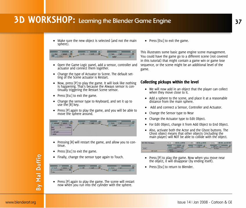
Make sure the new object is selected (and not the mainsphere).
Open the Game Logic panel, add a sensor, controller andactuator and connect them together.
Change the type of Actuator to Scene. The default set-ting of the Scene actuator is Restart.
Now, press [P] to play the game. It will look like nothingis happening. That's because the Always sensor is con-tinually triggering the Restart Scene sensor.
Press [Esc] to exit the game.
Change the sensor type to Keyboard, and set it up touse the [R] key.
Press [P] again to play the game, and you will be able tomove the sphere around.
Pressing [R] will restart the game, and allow you to con-tinue.
Press [Esc] to exit the game.
Finally, change the sensor type again to Touch.
Press [P] again to play the game. The scene will restartnow when you run into the cylinder with the sphere.
Press [Esc] to exit the game.
This illustrates some basic game engine scene management.You could have the game go to a different scene (not coveredin this tutorial) that might contain a game win or game losesequence, or the scene might be an additional level of thegame.
Collecting pickups within the level
We will now add in an object that the player can collectwhen they move close to it.
Add a sphere to the scene, and place it at a reasonabledistance from the main sphere.
Add and connect a Sensor, Controller and Actuator.
Change the Sensor type to Near
Change the Actuator type to Edit Object.
For Edit Object, change it from Add Object to End Object.
Also, activate both the Actor and the Ghost buttons. TheGhost object means that other objects (including themain player) will NOT be able to collide with the object.
Press [P] to play the game. Now when you move nearthe object, it will disappear (by ending itself).
Press [Esc] to return to Blender.
3D WORKSHOP: Learning the Blender Game Engine
By M
al D
uffin
37
www.blenderart.org Issue 14 | Jan 2008 - Cartoon & GE
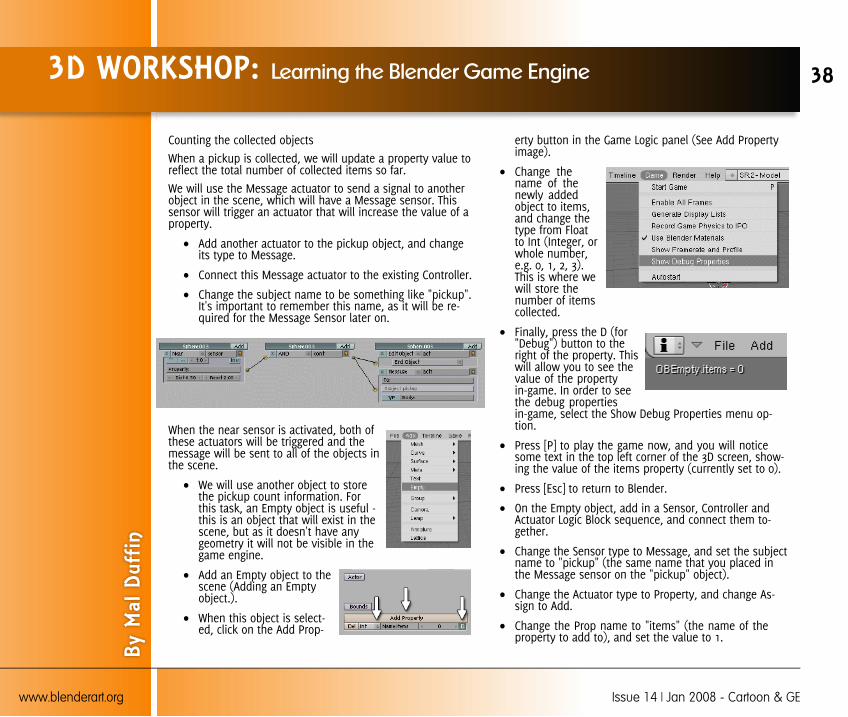
Counting the collected objects
When a pickup is collected, we will update a property value toreflect the total number of collected items so far.
We will use the Message actuator to send a signal to anotherobject in the scene, which will have a Message sensor. Thissensor will trigger an actuator that will increase the value of aproperty.
Add another actuator to the pickup object, and changeits type to Message.
Connect this Message actuator to the existing Controller.
Change the subject name to be something like "pickup".It's important to remember this name, as it will be re-quired for the Message Sensor later on.
When the near sensor is activated, both ofthese actuators will be triggered and themessage will be sent to all of the objects inthe scene.
We will use another object to storethe pickup count information. Forthis task, an Empty object is useful -this is an object that will exist in thescene, but as it doesn't have anygeometry it will not be visible in thegame engine.
Add an Empty object to thescene (Adding an Emptyobject.).
When this object is select-ed, click on the Add Prop-
erty button in the Game Logic panel (See Add Propertyimage).
Change thename of thenewly addedobject to items,and change thetype from Floatto Int (Integer, orwhole number,e.g. 0, 1, 2, 3).This is where wewill store thenumber of itemscollected.
Finally, press the D (for"Debug") button to theright of the property. Thiswill allow you to see thevalue of the propertyin-game. In order to seethe debug propertiesin-game, select the Show Debug Properties menu op-tion.
Press [P] to play the game now, and you will noticesome text in the top left corner of the 3D screen, show-ing the value of the items property (currently set to 0).
Press [Esc] to return to Blender.
On the Empty object, add in a Sensor, Controller andActuator Logic Block sequence, and connect them to-gether.
Change the Sensor type to Message, and set the subjectname to "pickup" (the same name that you placed inthe Message sensor on the "pickup" object).
Change the Actuator type to Property, and change As-sign to Add.
Change the Prop name to "items" (the name of theproperty to add to), and set the value to 1.
3D WORKSHOP: Learning the Blender Game Engine
By M
al D
uffin
38
www.blenderart.org Issue 14 | Jan 2008 - Cartoon & GE
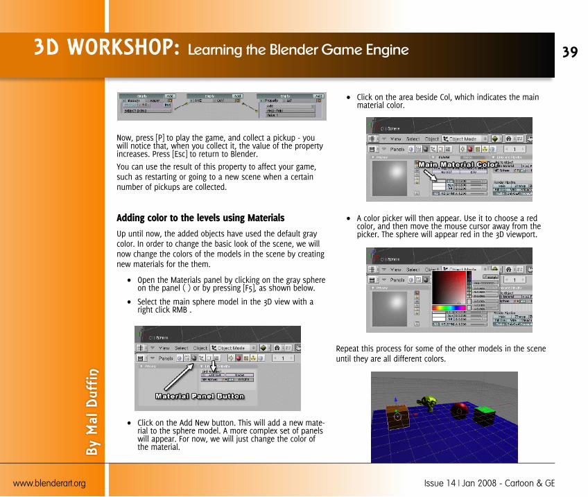
Now, press [P] to play the game, and collect a pickup - youwill notice that, when you collect it, the value of the propertyincreases. Press [Esc] to return to Blender.
You can use the result of this property to affect your game,such as restarting or going to a new scene when a certainnumber of pickups are collected.
Adding color to the levels using MaterialsUp until now, the added objects have used the default graycolor. In order to change the basic look of the scene, we willnow change the colors of the models in the scene by creatingnew materials for the them.
Open the Materials panel by clicking on the gray sphereon the panel ( ) or by pressing [F5], as shown below.
Select the main sphere model in the 3D view with aright click RMB .
Click on the Add New button. This will add a new mate-rial to the sphere model. A more complex set of panelswill appear. For now, we will just change the color ofthe material.
Click on the area beside Col, which indicates the mainmaterial color.
A color picker will then appear. Use it to choose a redcolor, and then move the mouse cursor away from thepicker. The sphere will appear red in the 3D viewport.
Repeat this process for some of the other models in the sceneuntil they are all different colors.
3D WORKSHOP: Learning the Blender Game Engine
By M
al D
uffin
39
www.blenderart.org Issue 14 | Jan 2008 - Cartoon & GE
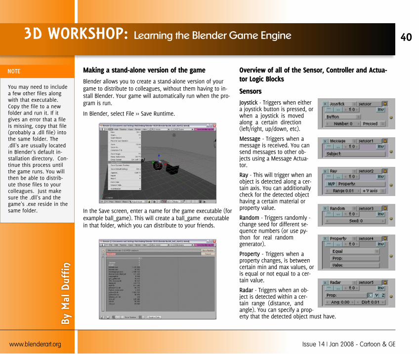
Making a stand-alone version of the gameBlender allows you to create a stand-alone version of yourgame to distribute to colleagues, without them having to in-stall Blender. Your game will automatically run when the pro-gram is run.
In Blender, select File >> Save Runtime.
In the Save screen, enter a name for the game executable (forexample ball_game). This will create a ball_game executablein that folder, which you can distribute to your friends.
Overview of all of the Sensor, Controller and Actua-tor Logic Blocks
Sensors- Triggers when either
a joystick button is pressed, orwhen a joystick is movedalong a certain direction(left/right, up/down, etc).
- Triggers when amessage is received. You cansend messages to other ob-jects using a Message Actua-tor.
- This will trigger when anobject is detected along a cer-tain axis. You can additionallycheck for the detected objecthaving a certain material orproperty value.
- Triggers randomly -change seed for different se-quence numbers (or use py-thon for real randomgenerator).
- Triggers when aproperty changes, is betweencertain min and max values, oris equal or not equal to a cer-tain value.
- Triggers when an ob-ject is detected within a cer-tain range (distance, andangle). You can specify a prop-erty that the detected object must have.
3D WORKSHOP: Learning the Blender Game Engine
By M
al D
uffin
40
www.blenderart.org Issue 14 | Jan 2008 - Cartoon & GE
You may need to includea few other files alongwith that executable.Copy the file to a newfolder and run it. If itgives an error that a fileis missing, copy that file(probably a .dll file) intothe same folder. The.dll's are usually locatedin Blender's default in-stallation directory. Con-tinue this process untilthe game runs. You willthen be able to distrib-ute those files to yourcolleagues. Just makesure the .dll's and thegame's .exe reside in thesame folder.

- Triggers when an ob-ject is detected within a cer-tain distance. You canspecify a property that thedetected object must have.
- Triggers when theobject is in collision withanother object. You canspecify a material or a prop-erty that the collided objectmust have.
- Triggers when anobject is touching anotherobject. You can specify aproperty that the touchedobject must have.
- Triggers when cer-tain mouse events occur,such as mouse button clicks,mouse movement, etc.
- Triggers when acertain key is pressed.
Always - Triggers every singleframe.
Controllers: Controllers are triggered by their attached sen-sors.
- Runs the connectedactuator if ALL of the con-necting sensors are trig-gered.
- Runs the connected actuatorif ANY of the connecting sensorsare triggered.
- Evaluates an expres-sion.
- Runs a python script.
Actuators: If the relevant sen-sors are triggered, the controllerwill call the connected actuator(s).
Visibility - Show and hide the cur-rent object.
- Restart and Quit the cur-rent level. Can also load a newscene.
- Allows for control over CDmusic tracks.
- Send a message to allobjects, or to a certain object. Thismessage will trigger the MessageSensor.
- Sets a random valueinto a property of the object.
- Allows for control overscenes - loading, playing, sus-pending, etc.
This is very useful for showing different scenes, such as astart-up scene or menu. When the user wants to play the ac-tual game, a keyboard sensor (e.g. press [Space] to play)could be connected to a scene sensor, which would then loadup the game scene.
3D WORKSHOP: Learning the Blender Game Engine
By M
al D
uffin
41
www.blenderart.org Issue 14 | Jan 2008 - Cartoon & GE
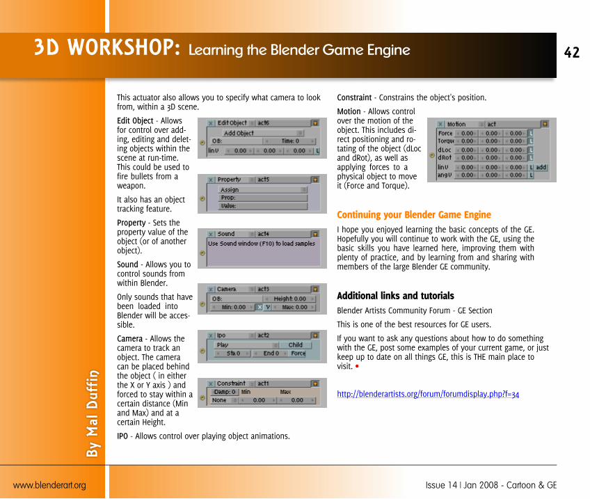
This actuator also allows you to specify what camera to lookfrom, within a 3D scene.
- Allowsfor control over add-ing, editing and delet-ing objects within thescene at run-time.This could be used tofire bullets from aweapon.
It also has an objecttracking feature.
- Sets theproperty value of theobject (or of anotherobject).
- Allows you tocontrol sounds fromwithin Blender.
Only sounds that havebeen loaded intoBlender will be acces-sible.
- Allows thecamera to track anobject. The cameracan be placed behindthe object ( in eitherthe X or Y axis ) andforced to stay within acertain distance (Minand Max) and at acertain Height.
- Allows control over playing object animations.
- Constrains the object's position.
- Allows controlover the motion of theobject. This includes di-rect positioning and ro-tating of the object (dLocand dRot), as well asapplying forces to aphysical object to moveit (Force and Torque).
Continuing your Blender Game EngineI hope you enjoyed learning the basic concepts of the GE.Hopefully you will continue to work with the GE, using thebasic skills you have learned here, improving them withplenty of practice, and by learning from and sharing withmembers of the large Blender GE community.
Additional links and tutorialsBlender Artists Community Forum - GE Section
This is one of the best resources for GE users.
If you want to ask any questions about how to do somethingwith the GE, post some examples of your current game, or justkeep up to date on all things GE, this is THE main place tovisit.
http://blenderartists.org/forum/forumdisplay.php?f=34
3D WORKSHOP: Learning the Blender Game Engine
By M
al D
uffin
42
www.blenderart.org Issue 14 | Jan 2008 - Cartoon & GE
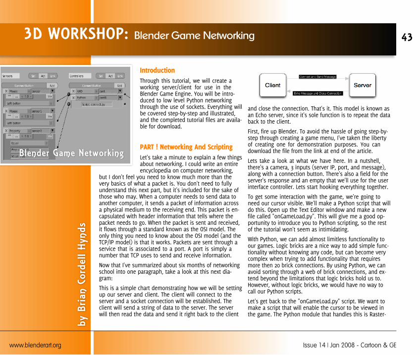
IntroductionThrough this tutorial, we will create aworking server/client for use in theBlender Game Engine. You will be intro-duced to low level Python networkingthrough the use of sockets. Everything willbe covered step-by-step and illustrated,and the completed tutorial files are availa-ble for download.
PART ! Networking And ScriptingLet's take a minute to explain a few thingsabout networking. I could write an entireencyclopedia on computer networking,
but I don't feel you need to know much more than thevery basics of what a packet is. You don't need to fullyunderstand this next part, but it's included for the sake ofthose who may. When a computer needs to send data toanother computer, it sends a packet of information acrossa physical medium to the receiving end. This packet is en-capsulated with header information that tells where thepacket needs to go. When the packet is sent and received,it flows through a standard known as the OSI model. Theonly thing you need to know about the OSI model (and theTCP/IP model) is that it works. Packets are sent through aservice that is associated to a port. A port is simply anumber that TCP uses to send and receive information.
Now that I've summarized about six months of networkingschool into one paragraph, take a look at this next dia-gram:
This is a simple chart demonstrating how we will be settingup our server and client. The client will connect to theserver and a socket connection will be established. Theclient will send a string of data to the server. The serverwill then read the data and send it right back to the client
and close the connection. That's it. This model is known asan Echo server, since it's sole function is to repeat the databack to the client.
First, fire up Blender. To avoid the hassle of going step-by-step through creating a game menu, I've taken the libertyof creating one for demonstration purposes. You candownload the file from the link at end of the article.
Lets take a look at what we have here. In a nutshell,there's a camera, 3 inputs (server IP, port, and message),along with a connection button. There's also a field for theserver's response and an empty that we'll use for the userinterface controller. Lets start hooking everything together.
To get some interaction with the game, we're going toneed our cursor visible. We'll make a Python script that willdo this. Open up the Text Editor window and make a newfile called "onGameLoad.py". This will give me a good op-portunity to introduce you to Python scripting, so the restof the tutorial won't seem as intimidating.
With Python, we can add almost limitless functionality toour games. Logic bricks are a nice way to add simple func-tionality without knowing any code, but can become verycomplex when trying to add functionality that requiresmore then 20 brick connections. By using Python, we canavoid sorting through a web of brick connections, and ex-tend beyond the limitations that logic bricks hold us to.However, without logic bricks, we would have no way tocall our Python scripts.
Let's get back to the "onGameLoad.py" script. We want tomake a script that will enable the cursor to be viewed inthe game. The Python module that handles this is Raster-
3D WORKSHOP: Blender Game Networking
by B
rian
Cord
ell H
ynds
43
www.blenderart.org Issue 14 | Jan 2008 - Cartoon & GE
Blender Game Networking
zer. To access the Rasterizer functions, we will first need toimport the module into our script. After a module is imported,you will have access to all of it's functions. You can import thescript using "import [module]". To save typing, we'll use the"as [name]" option. This helps tremendously when creatingvery long scripts that require you to type the module name alot.
import Rasterizer as r
To show the mouse on screen, we'll use the showMouse()function like this:
r.showMouse(1)
Notice, to call the showMouse() function, we needed to refer-ence the module first. To call any functions contained within amodule, you reference them in"module.function().subfunction()" order.
Another thing to take note of is the function's attribute. In thiscase, I am using "1" to reference a 'True' value. 'False' is repre-sented as "0". In fact, any non-zero value is a 'True' value. Wecould have also used "r.showMouse(True)" and it will workjust the same. This is a matter of personal preference, but Ithink typing "1" and "0" is much faster and easier than 'True'and 'False'.
Now that our script is made, we need to create some logicbricks that will call them. We'll assign them to our empty,called "GameController". Select the empty and pull up theLogic Bricks window [F4]. Add an Always Sensor and disableTrue level pulsing. Then add a Python controller. This is wherewe enter the name of the script to be loaded. Connect thedots, and test out the game. You should now be able to seeyour cursor in the game view.
That should give you a good understanding of how Pythonscripts are handled in the game engine. Now let's get out ofbeginner mode and have a look at some real coding. Fromhere on out, I'm not going to explain everything as "click this","point here", etc. If you're seriously looking to add networkinginto your games, you should have a good understanding ofthe basics by now.
Part 2 : Setting Up the Python ServerSince we got our beginner course out of the way (quite possi-bly a primer for some), let's get our basic TCP Python serverrunning. I like to use the Blender Text Editor to edit myscripts, mostly because I hate switching back and forth be-tween applications. [CTRL+W] will save the .blend file, and[ALT+S] will save the text file outside of the .blend.
This next script will need to be saved outside of the .blendfile, because it will be our server application. I have tried tofind ways to run the server easily within the game itself, but Icannot find any easy way to do this. Running it outside ofBlender will also make it much faster in responding and han-dling client connections.
So lets have a look at the heart of the networking relationship,the server. As I mentioned before, we're going to use Pythonsockets to make the connection between the client and theserver. I'm going to show you the TCP Python server we'll beusing, and within the code I'll break it down into understanda-ble pieces using comments.
3D WORKSHOP: Blender Game Networking
By B
rian
Cord
ell H
ynds
44
www.blenderart.org Issue 14 | Jan 2008 - Cartoon & GE
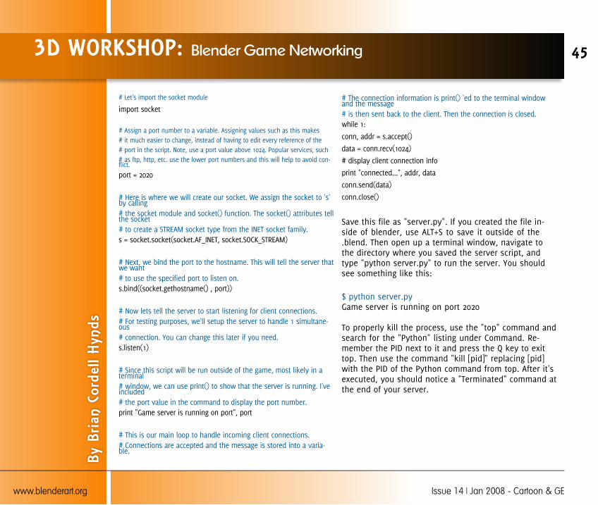
# Let's import the socket module
import socket
# Assign a port number to a variable. Assigning values such as this makes# it much easier to change, instead of having to edit every reference of the# port in the script. Note, use a port value above 1024. Popular services, such# as ftp, http, etc. use the lower port numbers and this will help to avoid con-flict.
port = 2020
# Here is where we will create our socket. We assign the socket to 's'by calling# the socket module and socket() function. The socket() attributes tellthe socket# to create a STREAM socket type from the INET socket family.s = socket.socket(socket.AF_INET, socket.SOCK_STREAM)
# Next, we bind the port to the hostname. This will tell the server thatwe want# to use the specified port to listen on.s.bind((socket.gethostname() , port))
# Now lets tell the server to start listening for client connections.# For testing purposes, we'll setup the server to handle 1 simultane-ous# connection. You can change this later if you need.s.listen(1)
# Since this script will be run outside of the game, most likely in aterminal# window, we can use print() to show that the server is running. I'veincluded# the port value in the command to display the port number.print "Game server is running on port", port
# This is our main loop to handle incoming client connections.# Connections are accepted and the message is stored into a varia-ble.
# The connection information is print() 'ed to the terminal windowand the message# is then sent back to the client. Then the connection is closed.while 1:
conn, addr = s.accept()
data = conn.recv(1024)
# display client connection info
print "connected...", addr, data
conn.send(data)
conn.close()
Save this file as "server.py". If you created the file in-side of blender, use ALT+S to save it outside of the.blend. Then open up a terminal window, navigate tothe directory where you saved the server script, andtype "python server.py" to run the server. You shouldsee something like this:
$ python server.pyGame server is running on port 2020
To properly kill the process, use the "top" command andsearch for the "Python" listing under Command. Re-member the PID next to it and press the Q key to exittop. Then use the command "kill [pid]" replacing [pid]with the PID of the Python command from top. After it'sexecuted, you should notice a "Terminated" command atthe end of your server.
3D WORKSHOP: Blender Game Networking
By B
rian
Cord
ell H
ynds
45
www.blenderart.org Issue 14 | Jan 2008 - Cartoon & GE

Part 3 : Creating the ClientNow that we have a running server, it's not going to do muchif we don't create our clients. Using the .blend file from theprevious articles (here), let's set a few things up before creat-ing the client code.
First off, if you look at the menu, you'll notice there are 3 in-puts: Server IP (input1), Port (input2) and Message (input3)are used to create the connection with the server. Currently,there's no easy way to enter the data for multiple text objects,so we'll have to script it.
Before we do, select each input object and create two proper-ties. The first one being a string named "Text" and the secondone as a bool named "edit". Set input1's edit property to True,and the others to false. This will give us somewhere to start.
I'm just going to summarize the script, instead of walking youthrough it step-by-step. We create a trigger that checks to see
if a Sensor (a Keyboard Sensor) is positive. If it is, then wecreate a Python list of the 3 input objects. Then, we run anif/elif loop to set the "edit" properties of the appropriate in-puts according to which conditional statement is true. Simpleenough.
Here's the script. Save this as "tabController.py" in the BlenderText Editor.
import GameLogic as gl
cont = gl.getCurrentController()
trigger = cont.getSensor("tabcheck")
if trigger.isPositive():
# get objects
input1 = gl.getCurrentScene().getObjectList()["OBinput1"] # server ip
input2 = gl.getCurrentScene().getObjectList()["OBinput2"] # portnumber
input3 = gl.getCurrentScene().getObjectList()["OBinput3"] # message
proplist = [input1, input2, input3]
# server => port
if (proplist[0].edit == 1):
proplist[0].edit = 0
proplist[1].edit = 1
proplist[2].edit = 0
# port => message
elif (proplist[1].edit == 1):
proplist[0].edit = 0
proplist[1].edit = 0
proplist[2].edit = 1
# message => server
elif (proplist[2].edit == 1):
proplist[0].edit = 1
proplist[1].edit = 0
proplist[2].edit = 0
3D WORKSHOP: Blender Game Networking
By B
rian
Cord
ell H
ynds
46
www.blenderart.org Issue 14 | Jan 2008 - Cartoon & GE

Select the "GameController" empty and setup a Keyboard Sen-sor. For this exercise, I am going to be using the Return key,simply because using the Tab key actually produces "@" keyreturns which mess up the text input. You could use the Tabkey if you want, but you'll have to edit the script to removethe "@" in the text object. Connect this Keyboard Sensor to aPython Controller, and use the "tabController.py" file.
Here's where a few problems lie within the logic brick design.What we need to do is create two Mouse Sensors ("Mouseover" and "Left button"), and when they are both positive aPython script is started. At first glance you might think, "Well,hook them both up to a Python script controller". This isn'tgoing to work because each Mouse Sensor will act independ-
ently as if it were an OR condition, and the script will runevery time a left mouse button is pressed and every time youmouse over the button. We need to connect them to an ANDcontroller, but now we're presented with the problem of notbeing able to run the script directly. Since there is no PythonActuator, we're going to use the Property Actuator to set abool property, which will trigger a Property Sensor that will
initialize the script. Take a look at theimage below to see how this works:
Onto the script. Much like the serverscript, I'm going to show you thescript we'll be using, and then usecomments within the script to explainwhat's going on.
3D WORKSHOP: Blender Game Networking
By B
rian
Cord
ell H
ynds
47
www.blenderart.org Issue 14 | Jan 2008 - Cartoon & GE

# Since we'll be using Blender Game Engine functions,# we need to import the GameLogic module.import socket
import GameLogic as gl
# This is another problem with the logic bricks. We can initialize scriptsusing the# Python controller, but we can't stop them when their sensor is nottrue. If we don't# check the property, the script will actually run twice (on click and onrelease).# We'll create a loop to test if the property is true, this way we onlyrun it once.conprop = gl.getCurrentController().getOwner()
if (conprop.connect == True):
# Now let's get the "Text" property values from the input objects, andassign# them to respective variables. Notice that we need to use the int()function# for the port settings. If we don't, the variable is assigned as a string,and# you will get an error when binding the port because it's not an inte-ger value.hostinput = gl.getCurrentScene().getObjectList()["OBinput1"]
host = hostinput.Text
portinput = gl.getCurrentScene().getObjectList()["OBinput2"]
portstring = portinput.Text
port = int(portstring)
# As with the server, we create the socket.
s = socket.socket(socket.AF_INET, socket.SOCK_STREAM)
# Instead of listening for connections, we'll connect to the server.
s.connect((host, port))
# We'll grab the message from input3 and use the the send() function# to send it to the server.message = gl.getCurrentScene().getObjectList()["OBinput3"]
sendme = message.Text
s.send(sendme)
# Assign the server response to a variable,# so we can use it later, and close the connection.data = s.recv(1024)
s.close()
# Now we can display the echoed message in the server response# text object by assigning it to it's Text property.resp = gl.getCurrentScene().getObjectList()["OBresponseValue"]
resp.Text = data
# And finally, we reset the connect property back to false.
conprop.connect = 0 Summary
Let's test it all out. Fire up the server, then play the game. Typein the IP of the server, the port number the server is runningon, and a message you'd like to send. Press connect, and if allwent well, the server should respond with your echoed mes-sage which is displayed in the response area. You can see theconnections printed in the server terminal window. Hopefully,this will have given you a good understanding how simplesocket connections are made and how you can get networkingwithin your games.
You can download the entire .blend file, which includes theserver and the game client, here.
3D WORKSHOP: Blender Game Networking
By B
rian
Cord
ell H
ynds
48
www.blenderart.org Issue 14 | Jan 2008 - Cartoon & GE

In my next article, we'll cover how to design a simple Pythonchat server, complete with password authentication, and set-ting up the Blender UI to create a chat client in the game en-gine.
Until then, if you have any questions, comments, or problems,feel free to e-mail me at [email protected], or jump into thediscussion at BlenderArtists in this forum thread:
http://blenderartists.org/forum/showthread.php?t=111532
3D WORKSHOP: Blender Game Networking
By B
rian
Cord
ell H
ynds
49
www.blenderart.org Issue 14 | Jan 2008 - Cartoon & GE

Introduction For those of you who are followers of the BlenderArtMagazine, I’m sure that at least one of the characters inthe picture isn’t a complete stranger to you. That’s Ori-on, who was presented for the first time in issue #4 -Character Design. From that issue almost until thepresent day, he was working as one of the main actorsof my 10 minute short animation, Orion Tear!
Orion Tear: Orion Tear is my first short animationmovie. It was made with only Blender, Gimp, Inkscape,one workstation and me during 19 months and 7 daysof non stop, from dawn till dusk, work. Although all thegraphical part of the movie is done, the sound is stillbeing developed by Telmo Cavaleiro, one local musicianand sound EFX enthusiast, in his free time. It's releasedate is still undefined, but everything points to lateWinter/early Spring 2008.
Origin: Ever since my eyes glazed watching the fullmotion videos of a video game called Final Fantasy 8,from the former company, SquareSoft, I knew that wasthe type of thing I wanted to do with my life. Consider-ing that, at the time, I found the task of drawing asquare with a ruler extremely hard... I also knew that I
was in trouble!
Two years after that, I found an article in a Portuguese video-games magazine, describing the wonders of one revolution-ary 3D application especially created for game development,called Blender 2.0. That precious 1Mb of pure creative powercame in the CD, so I said to myself: “Well, I don’t care aboutmaking games, but, what the hell; this is my chance to dis-cover if I can do movies!”
And guess what? From that day on, I continuallyimproved…until the day some guys made an open moviecalled Elephants Dream (ED) with the very same software I’ve
MAKING OF: ‘Orion Tear’
by R
ogér
io P
erdi
z
50
www.blenderart.org Issue 14 | Jan 2008 - Cartoon & GE
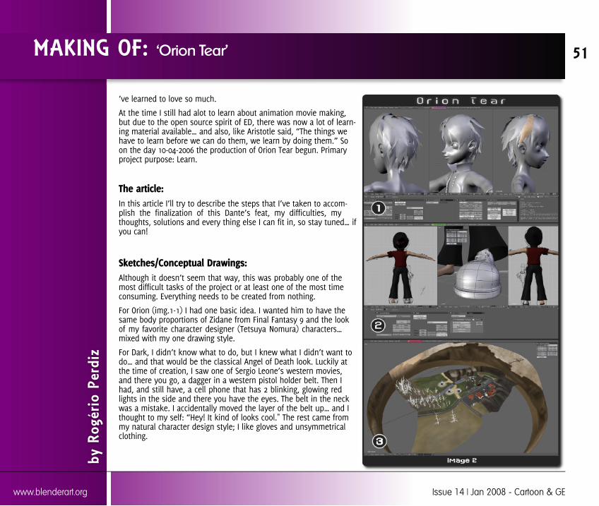
’ve learned to love so much.
At the time I still had alot to learn about animation movie making,but due to the open source spirit of ED, there was now a lot of learn-ing material available… and also, like Aristotle said, “The things wehave to learn before we can do them, we learn by doing them.” Soon the day 10-04-2006 the production of Orion Tear begun. Primaryproject purpose: Learn.
The article:In this article I’ll try to describe the steps that I’ve taken to accom-plish the finalization of this Dante’s feat, my difficulties, mythoughts, solutions and every thing else I can fit in, so stay tuned… ifyou can!
Sketches/Conceptual Drawings:Although it doesn’t seem that way, this was probably one of themost difficult tasks of the project or at least one of the most timeconsuming. Everything needs to be created from nothing.
For Orion (img.1-1) I had one basic idea. I wanted him to have thesame body proportions of Zidane from Final Fantasy 9 and the lookof my favorite character designer (Tetsuya Nomura) characters…mixed with my one drawing style.
For Dark, I didn’t know what to do, but I knew what I didn’t want todo… and that would be the classical Angel of Death look. Luckily atthe time of creation, I saw one of Sergio Leone’s western movies,and there you go, a dagger in a western pistol holder belt. Then Ihad, and still have, a cell phone that has 2 blinking, glowing redlights in the side and there you have the eyes. The belt in the neckwas a mistake. I accidentally moved the layer of the belt up… and Ithought to my self: “Hey! It kind of looks cool." The rest came frommy natural character design style; I like gloves and unsymmetricalclothing.
MAKING OF: ‘Orion Tear’
by R
ogér
io P
erdi
z
51
www.blenderart.org Issue 14 | Jan 2008 - Cartoon & GE

The sceneries simply evolved. I started to model them rightaway.
I wanted something that had kind of a natural feel with a sub-tle Fantasy look. Basically I’ve started from the look of onereal beach place, near to my house, and then mixed it withsome valley type of place. But something was missing, it sim-ply wasn’t catchy enough. So one weekend I grabbed my bicy-cle and went for a ride, without a fixed destination, hoping tofind something to improve it. I still don't know how, but I lostmyself and while trying to find my way back I found insteadone very old wind mill. First I almost completely ignored it andkept on my way, still looking for something for my scenerybut, after a while, I start to think:
”Darn!!! I haven’t seen one of those mills working, for dec-ades… funny to find one today… Hum! A mill… Mill!?”
I immediately squeezed the brake handles starting a sudden180º breaking stop, returned as fast as my bike allowed, tooka bunch of pictures and after finding my way home I modeledit and there you have it.
After that I made some very rough sketches of the final scen-ery layout, having Mills as the theme (img.1-2) and then mod-eled a much too detailed version that turned out to beimpossible to use... more of that in the next chapters.
After that I made some very rough sketches of the final scen-ery layout, having Mills as the theme (img.1-2) and then mod-eled a much too detailed version that turned out to beimpossible to use... more of that in the next chapters.
Note: During this article, by scenery, I will be referring just to themain Mills scenery (img. 2-3). The movie has 3 sceneries, one in themountains (img. 6-1) and another one that is a surprise!
Modeling Characters:My model skills at the time were already pretty good, so, be-cause I had defined all the details during the conceptual
phase, I’ve just loaded the images to the blender viewportsand start to model.
I started Orion with his Head, eyes and hair; then the bodyand finally the clothes. By the way, the Orion model that ap-pears in the issue #4 had to be 80% remodeled due to prob-lems in rigging, more on that in the rigging chapter.
For all the body and shoes I’ve used the point by point tech-nique, meaning I’ve positioned all the points in space, basedon the hand drawings, and only then joined them makingfaces.
The cloths were made initially by several nurbs circles thatI’ve joined forming tubes (sadly I lost the screenshots of thatand this is kind difficult to explain). For example: basically ashirt is only a subdivided tube that starts in one hand andends in the other.
Then converting the nurbs tubes to meshes I could delete thefaces that didn’t matter. For example, the ones in the placewhere the body and neck passes through. After some adjust-ing and loop cutting what you get is a very good mesh topol-ogy shirt that deforms pretty good.
Scenery:The scenery was my first problem. The first version was muchtoo detailed, with lots of unnecessary polygons. I really didn’tknow about the limitations of my workstation, so I made tonsof stuff until eventually everything moved excruciatingly slow.I thought: “well, it’s slow but it should do the trick”! But itdidn’t. I had generated 2 millions polygons. Happy and full ofjoy with my self, I pressed Render and guess what? Right! 1hour of render time which doesn’t work very well for anima-tion using only one PC, besides that Windows O.S. has an an-noying 1.5 GB memory limitation and from some angles, richin polygons, it didn’t render at all.
MAKING OF: ‘Orion Tear’
by R
ogér
io P
erdi
z
52
www.blenderart.org Issue 14 | Jan 2008 - Cartoon & GE
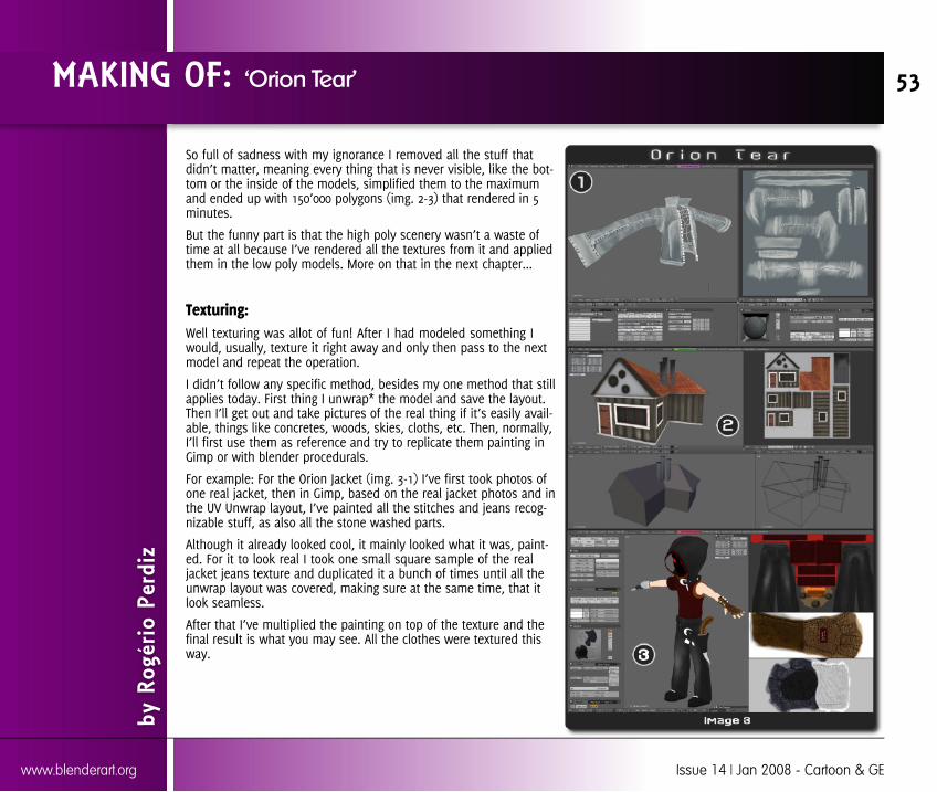
So full of sadness with my ignorance I removed all the stuff thatdidn’t matter, meaning every thing that is never visible, like the bot-tom or the inside of the models, simplified them to the maximumand ended up with 150’000 polygons (img. 2-3) that rendered in 5minutes.
But the funny part is that the high poly scenery wasn’t a waste oftime at all because I’ve rendered all the textures from it and appliedthem in the low poly models. More on that in the next chapter...
Texturing:Well texturing was allot of fun! After I had modeled something Iwould, usually, texture it right away and only then pass to the nextmodel and repeat the operation.
I didn’t follow any specific method, besides my one method that stillapplies today. First thing I unwrap* the model and save the layout.Then I’ll get out and take pictures of the real thing if it’s easily avail-able, things like concretes, woods, skies, cloths, etc. Then, normally,I’ll first use them as reference and try to replicate them painting inGimp or with blender procedurals.
For example: For the Orion Jacket (img. 3-1) I’ve first took photos ofone real jacket, then in Gimp, based on the real jacket photos and inthe UV Unwrap layout, I’ve painted all the stitches and jeans recog-nizable stuff, as also all the stone washed parts.
Although it already looked cool, it mainly looked what it was, paint-ed. For it to look real I took one small square sample of the realjacket jeans texture and duplicated it a bunch of times until all theunwrap layout was covered, making sure at the same time, that itlook seamless.
After that I’ve multiplied the painting on top of the texture and thefinal result is what you may see. All the clothes were textured thisway.
MAKING OF: ‘Orion Tear’
by R
ogér
io P
erdi
z
53
www.blenderart.org Issue 14 | Jan 2008 - Cartoon & GE

About the scenery:Most of the textures of the low poly set are renderings of the highpoly set enhanced in Gimp :) For ex.: the house (img. 3-2); from thehigh poly house I’ve rendered, only with Ambient Occlusion (still nobaking at the time :P), one wall, then in Gimp I’ve added texturedetails, repeating the same procedure for all the walls, roof, etc.,and them used it on the low poly model.
Almost everything was painted in Gimp, using after that the texturesample like I did for the clothes.
One thing that didn’t quite work out has I expected were the far faraway mountains (img. 2-3). They are made of one gigantic matepainting applied to a tube that surrounds the scenery. If you focus inthem you will note that when the camera moves, a really bad, notwanted, distortion effect occurs. After some research I’ve learnedthat is a known issue in the world of 3DCGi, too big textures usedthat way seem to be propitious to cause that effect.
Lots of people ask me how I made the sky: Well the sky is just 3blender procedural cloud textures mixed, and then the rest is a com-positing trick. I also made allot of testing to try to have some move-ment on the clouds, but, it wasn’t working at all so I moved on andleft them static.
Most of the wood textures are procedurals based on the ones of theBlender materials Library, v 1.01 from Zsolt Stefan enhanced by mein Gimp and UV mapped to the objects.
*UV Unwrapping (from blender wiki): During the UV unwrap-ping process, you tell Blender to map the faces of your object to aflat image in the UV/Image Editor window.
Rigging:This was the troublesome one. When I started I didn’t know anythingabout rigging, but thanks to Bassam Kurdali I was able to learn eve-rything!
MAKING OF: ‘Orion Tear’
by R
ogér
io P
erdi
z
54
www.blenderart.org Issue 14 | Jan 2008 - Cartoon & GE
Bassam made one full rigged character called Mancandy andshared it with everyone. Considering that, at the time, it wasthe most complex rig and at same time easy to use I’ve everseen I didn’t had any doubt… But I didn’t want to just importit to my characters; I wanted to learn, so I spent 2 weeks do-ing reverse engineering and creating the first Orion Rig. Well,after 2 weeks I had Orion rigged, but, I still didn’t really Knowhow to make a rig, so every thing was a bit clunky. It wasenough for walkcycles and basic movements, but I wantedthem to be able to compete with Jackie Chan!
So I’ve started again another rig, this time for Dark, expandingmy research to Emo and Proog rigs from ED. After anotherweek disassembling bones, trying to figuring out all that, Isuddenly started to see all the logic of the thing and progres-sively everything begun to make sense. Another 3 weekspassed until I successfully completed the Dark rig. After that Ireturned to Orion and because the first Orion mesh topologywas pretty bad, for deforming, I had to almost remodel every-thing and remade the rig. After another month I had themcompletely ready for action.
I will describe now the rigging procedure used for Orion Tear:
The first step is valid for all type of characters: We make the bone armature (img. 4-1); It’s necessary to define witch vertex are influenced by
each bone, we do that assigning vertex groups and us-ing weight painting for fine tuning (img. 4-2);
Corrective shape keys are added on top of everything toensure proper deformation, mainly, on places like joinsand pelvis.
The second step refers to the facial expressions:
A reasonable number of expression shape keys are cre-ated;
Control bones are added (img. 4-3); The shape keys are set to be driven by the control
bones.
The third step refers to everything related to the dynamics likecloth and hair movement: For the cloths:
I made a low poly version of the Jacket, that handlesthe softbody simulation
I added Empties, one for each vertex of the softbodymesh and made them vertex parent of their correspond-ent vertex;
Another armature constrained to the body armature wasrequired. The tip of the bones of that armature coin-cides with the Empties location and has a 1chain IK con-strain applied to them.
A softbody deflector is required (the orange objects inimg. 4-1) to avoid the cloth with body intersection. Imade each deflector parent of the respective bone.
Control bones are added (img. 4-3);
Basically this will make the Empties follow the softbody move-ment, the bones follow the Empties and the cloth mesh fol-lows the bones, originating an almost real time clothsimulation system.
The hair is a simple softbody with vertex painted influencecontrol. That’s why it isn’t good, in fact I don’t like the hair atall… not even the modeling, the texture nor the movement; Isimply don’t like it. But after spending so much time in it Ididn’t have the courage to remade it … and now some peopletell me that they love the hair, so hehe!
Animation:
Of all the other tasks of 3D animation movie making this oneis my favorite.
I had made some animations on the past, but nothing withrigged characters. So I made the scenes by animation difficulty
MAKING OF: ‘Orion Tear’
by R
ogér
io P
erdi
z
55
www.blenderart.org Issue 14 | Jan 2008 - Cartoon & GE
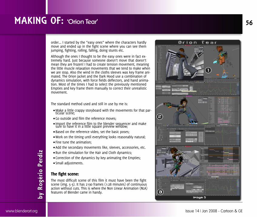
order... I started by the “easy ones” where the characters hardlymove and ended up in the fight scene where you can see themjumping, fighting, rolling, falling, doing stunts etc.
Although the ones I thought to be the easy ones were in fact ex-tremely hard. Just because someone doesn’t move that doesn’tmean they are frozen! I had to create tension movement, meaningthe little muscle relaxation movements that we tend to make whenwe are stop. Also the wind in the cloths sleeves was key frame ani-mated. The Orion jacket and the Dark Hood use a combination ofdynamics simulation, with force fields deflectors, and hand anima-tion. Most of the times I had to select the previously mentionedEmpties and key frame them manually to correct their unrealisticmovement.
The standard method used and still in use by me is:
Make a little crappy storyboard with the movements for that par-ticular scene; Go outside and film the reference moves; Import the reference film to the blender sequencer and makesure to have it in a little square preview window; Based on the reference video, set the basic poses; Work on the timing until everything looks reasonably natural; Fine tune the animation; Add the secondary movements like, sleeves, accessories, etc. Run the simulation for the Hair and Cloth dynamics; Correction of the dynamics by key animating the Empties; Small adjustments.
The fight scene:The most difficult scene of this film it must have been the fightscene (img. 5-3). It has 2190 frames (1:28 minutes) of continuousaction without cuts. This is where the Non Linear Animation (NLA)features of Blender came in handy.
MAKING OF: ‘Orion Tear’
by R
ogér
io P
erdi
z
56
www.blenderart.org Issue 14 | Jan 2008 - Cartoon & GE

Thanks to it I was able to make 11 individual Actions sequences (6for Dark and 5 for Orion) and Join them seamless in the NLA makingit look a big one take Action. The camera was animated in only onecontinuous action, seamlessly completing the illusion.
It took me long time to do, and awfully longer time to render. Thisone scene uses all the tricks I’ve learned in all the others previousscenes; more on that in the next chapter...
Render/Compositing:For me compositing is all about converting crappy renderings instunning final images by whatever tricks you can come up with ;)
I really don’t have any pre-established technique, this kind of thing Ido almost by instinct I guess. Some people could call it luck… butthat means I had luck 70 times (the number of scenes)!
The first thing needed is layers to mix. Because I couldn’t rendereverything at the same time, nor really wanted to, most of the timesI had 5 Base Layers to work with: scenery (to simplify the things abit, the set, that is composed by more then 10 layers, renders just toone), shadows, ambient occlusion, characters and volumetric effects.
All the layers were rendered to OpenEXR, which allows better colorcontrol, and after composed the scenes were re-rendered to uncom-pressed Quicktime which allowed better hard drive usage and organ-ization.
Lighting:The scenery is rendered with Ambient Occlusion. It has very “few”lamps: three fill lamps at the sides; one Sun lamp that coincideswith a Spot lamp for the sun volumetric halos; one lamp up andanother down… plus a few ones along the river to try to simulatesome Global Illumination (they are pretty much useless but I keptthem, don’t know why).
The characters use a Spot Lamp Dome* plus the sun lamp. Thecenter of the dome coincides with the characters position and fol
MAKING OF: ‘Orion Tear’
by R
ogér
io P
erdi
z
57
www.blenderart.org Issue 14 | Jan 2008 - Cartoon & GE
lows them wherever they go, resulting in a reasonablerenderTime/quality global illumination look. No Ambient Occlu-sion is used for the characters. For some scenes I’ve use anelaborate and very time consuming technique for creatingraytraced soft shadows (img. 6-2), that no one would note if Ididn’t mentioned it now and that I’ve abandoned in laterscenes due the viability of the thing!
First I’ve rendered all the character with a shadow-buffer spotlamp dome, and then rendered the skin and the shirt with araytraced shadows **spot lamp dome, but all in separatedlayers: Color, spec, shadows, etc, then reassembled themagain in compositor but this time with the shadows blurred.Three or four scenes use this method!
By the way, I made two versions of the scenery, one forrender and another, with much less detail for animation refer-ence. The characters never set foot on the real scenery. Thecamera had to be imported from the characters file to thescenery file for all the scenes.
The biggest challenge was to be able to keep lighting and themood consistent from scene to scene, because, most of it isjust compositing work and needed to be done for every scene.The scenery had an, per frame, average render time of 5 min-utes and the characters 7 minutes. Orion Tear took about 5months to render, fortunately, most of them during the night.Everything was rendered with blender internal renderer.
* Refers to the top half of an Icosphere mesh that has a SpotLamp parented to it and the DupliVerts plus Rot option turnedon, resulting in having one spot lamp per vertex pointing in-wards and towards the center of the dome.
** Raytraced shadows were very sharp edged. The currentblender CVS version doesn’t have that problem anymore.
Conclusion:Well the primary purpose of this project was 100% accom-plished. I’ve learned a lot… but I really don’t want to makesomething like this again, alone I mean! … and I don’t recom-mend to anyone to try it.
This is just my, at writing date, opinion… If you also want tolearn 3d animation movie making by making it, you probablyshouldn’t do more then 1 minute movies and you should fo-cus yourself in only one particular task on each movie, but,who knows...
I could write hundreds of pages about Orion Tear, but I guessthis article reasonably summarizes most of the things, so thisis the end of the ride with me. Hope you like Orion Tear, formore news keep an eye on blenderartist.org!
Links:Teaser: http://video.yahoo.com/video/play?vid=338577
Teaser-b: http://video.yahoo.com/video/play?vid=562159
Compositing: http://videos.sapo.pt/6ZsgTBaZLDZzABOdIy4d
Rigging: http://videos.sapo.pt/2h21Mr9M5lEoZtzJGzjV
About my self:I’m the guy that made Orion Tear, I’ve been using blendersince version 2.0 and hope to be a better animation moviemaker in the future ;)
e-mail:[email protected]
MAKING OF: ‘Orion Tear’
by R
ogér
io P
erdi
z
58
www.blenderart.org Issue 14 | Jan 2008 - Cartoon & GE
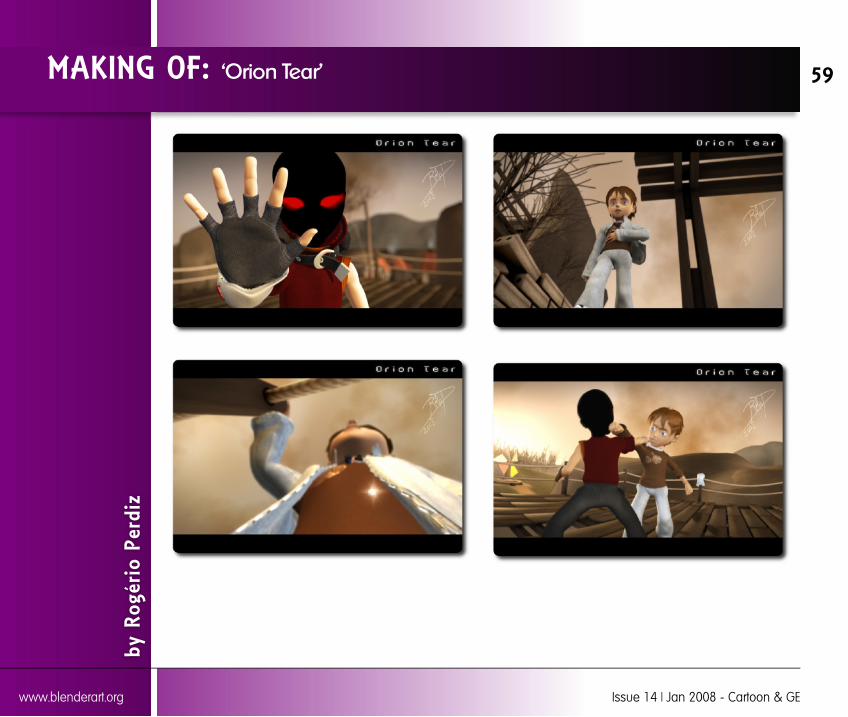
MAKING OF: ‘Orion Tear’
by R
ogér
io P
erdi
z
59
www.blenderart.org Issue 14 | Jan 2008 - Cartoon & GE
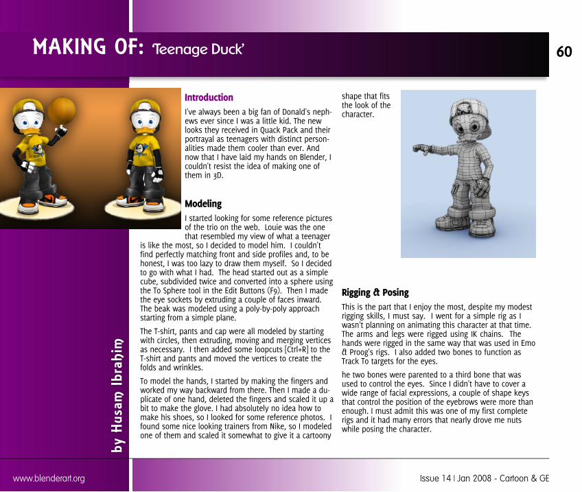
IntroductionI've always been a big fan of Donald's neph-ews ever since I was a little kid. The newlooks they received in Quack Pack and theirportrayal as teenagers with distinct person-alities made them cooler than ever. Andnow that I have laid my hands on Blender, Icouldn't resist the idea of making one ofthem in 3D.
ModelingI started looking for some reference picturesof the trio on the web. Louie was the onethat resembled my view of what a teenager
is like the most, so I decided to model him. I couldn'tfind perfectly matching front and side profiles and, to behonest, I was too lazy to draw them myself. So I decidedto go with what I had. The head started out as a simplecube, subdivided twice and converted into a sphere usingthe To Sphere tool in the Edit Buttons (F9). Then I madethe eye sockets by extruding a couple of faces inward.The beak was modeled using a poly-by-poly approachstarting from a simple plane.
The T-shirt, pants and cap were all modeled by startingwith circles, then extruding, moving and merging verticesas necessary. I then added some loopcuts [Ctrl+R] to theT-shirt and pants and moved the vertices to create thefolds and wrinkles.
To model the hands, I started by making the fingers andworked my way backward from there. Then I made a du-plicate of one hand, deleted the fingers and scaled it up abit to make the glove. I had absolutely no idea how tomake his shoes, so I looked for some reference photos. Ifound some nice looking trainers from Nike, so I modeledone of them and scaled it somewhat to give it a cartoony
shape that fitsthe look of thecharacter.
Rigging & PosingThis is the part that I enjoy the most, despite my modestrigging skills, I must say. I went for a simple rig as Iwasn't planning on animating this character at that time.The arms and legs were rigged using IK chains. Thehands were rigged in the same way that was used in Emo& Proog's rigs. I also added two bones to function asTrack To targets for the eyes.
he two bones were parented to a third bone that wasused to control the eyes. Since I didn't have to cover awide range of facial expressions, a couple of shape keysthat control the position of the eyebrows were more thanenough. I must admit this was one of my first completerigs and it had many errors that nearly drove me nutswhile posing the character.
MAKING OF: ‘Teenage Duck’
by H
usam
Ibr
ahim
60
www.blenderart.org Issue 14 | Jan 2008 - Cartoon & GE
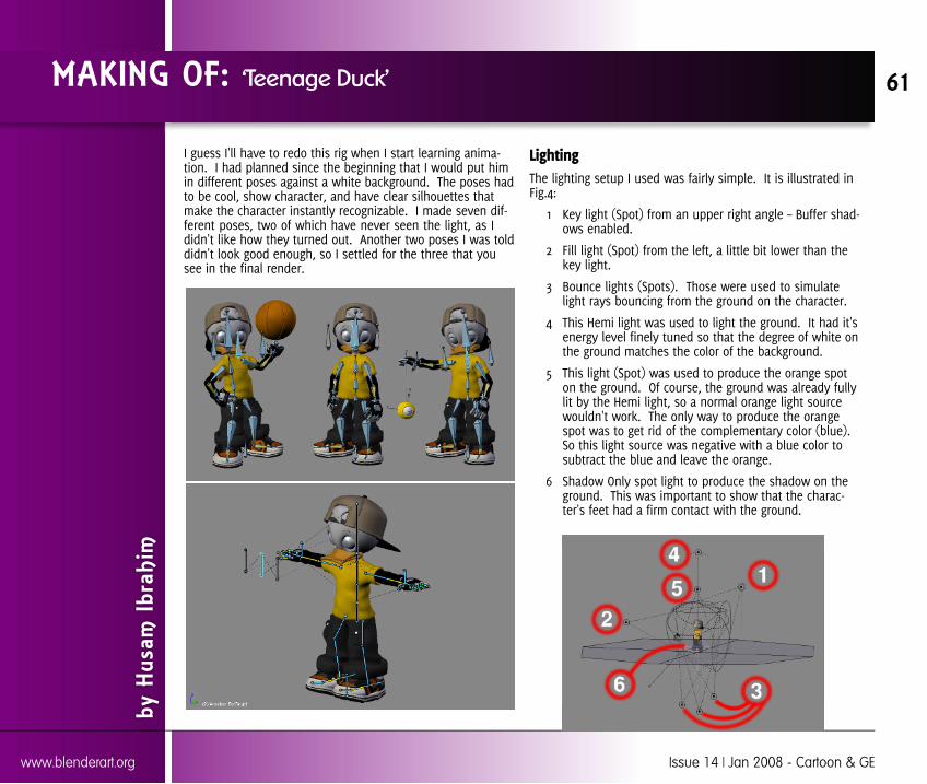
I guess I'll have to redo this rig when I start learning anima-tion. I had planned since the beginning that I would put himin different poses against a white background. The poses hadto be cool, show character, and have clear silhouettes thatmake the character instantly recognizable. I made seven dif-ferent poses, two of which have never seen the light, as Ididn't like how they turned out. Another two poses I was tolddidn't look good enough, so I settled for the three that yousee in the final render.
LightingThe lighting setup I used was fairly simple. It is illustrated inFig.4:
1 Key light (Spot) from an upper right angle – Buffer shad-ows enabled.
2 Fill light (Spot) from the left, a little bit lower than thekey light.
3 Bounce lights (Spots). Those were used to simulatelight rays bouncing from the ground on the character.
4 This Hemi light was used to light the ground. It had it'senergy level finely tuned so that the degree of white onthe ground matches the color of the background.
5 This light (Spot) was used to produce the orange spoton the ground. Of course, the ground was already fullylit by the Hemi light, so a normal orange light sourcewouldn't work. The only way to produce the orangespot was to get rid of the complementary color (blue).So this light source was negative with a blue color tosubtract the blue and leave the orange.
6 Shadow Only spot light to produce the shadow on theground. This was important to show that the charac-ter's feet had a firm contact with the ground.
MAKING OF: ‘Teenage Duck’
by H
usam
Ibr
ahim
61
www.blenderart.org Issue 14 | Jan 2008 - Cartoon & GE

The eyes had a lighting setup of their own. They had beenmodeled using the method described in the well-known"Creating Pixar-Looking Eyes in Blender” tutorial (Fig.5). If youlike that method of making the eyes as much as I do, youmust be using it and abusing it. But to get the most of it youreally need to pay close attention to the lighting. Unfortunate-ly, Blender doesn't allow assigning lights to different objects,so you'll just have to use different layers. I separated theirises from the eyes (to do this select them in Edit Mode, hitP, then choose “Selected”) and then placed each eye andeach iris on a separate layer.
Each eye was lit by a Hemi light and had a spot light carefullypositioned to get a specular highlight on the cornea. Each iriswas lit by a spotlight shining from an angle to get a nice colorgradient across the iris. This really makes it look a lot betterand gives some depth to it. Of course, you could achieve thesame effect by using a Blend texture mapped to the Color
channel of the iris with a Multiply blending mode, but control-ling the light angle wouldn't be as easy. I finally parented theirises and the lights to the eyes so that they look the samewherever they point.
Materials & ShadingIt was tempting at first to see what he would look like with 3Dshading. I have to admit it was a lousy idea. Sometimes youjust have to let the classics be the classics, if the term applies.So I decided to use a Toon shader for his body. What I don'tlike about the way people use the Toon shader in Blender isthat they like to have those sharp transitions between lit andshaded areas.
What people just don't seem to realize is that they can getnice looking toon characters by the exact opposite, a highly
smooth transition between lit and shaded areas.It also helps if you give the shader a medium-to-high “Size” value to make the shaded area assmall as possible, especially if your character is infront of a light background.
The other shaders I used were mainly Lambert forthe glove and Minnaert for the clothes and thebeak. It's really just a matter of playing with thesettings to see which combination works best.Nearly all the materials I used had a ramp shader,which gives a nice looking, peach-like color falloff.For the body material, the ramp shader didn't onlyserve the aesthetics of the image, but it alsohelped separate the character from the back-ground, as they had the same color.
The only textures I used were a jeans texture that Ifound on the web and the Mighty Ducks logo thatyou see on his chest. The logo needed some coloradjustments so that it would match with the colorof the T-shirt.
MAKING OF: ‘Teenage Duck’
by H
usam
Ibr
ahim
62
www.blenderart.org Issue 14 | Jan 2008 - Cartoon & GE
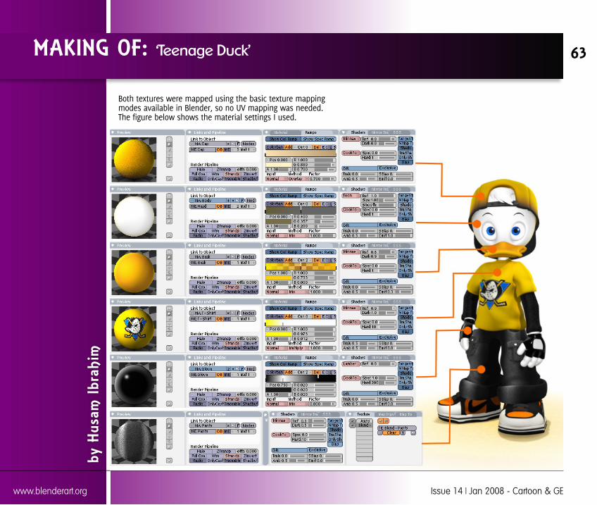
Both textures were mapped using the basic texture mappingmodes available in Blender, so no UV mapping was needed.The figure below shows the material settings I used.
MAKING OF: ‘Teenage Duck’
by H
usam
Ibr
ahim
63
www.blenderart.org Issue 14 | Jan 2008 - Cartoon & GE
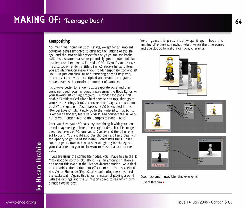
CompositingNot much was going on at this stage, except for an ambientocclusion pass I rendered to enhance the lighting of the im-age, and the motion blur effect for the yo-yo and the basket-ball. It's a shame that some potentially great renders fall flatjust because they need a little bit of AO. Even if you are mak-ing a cartoony render, a little bit of AO always helps, unlessyou are planning on making your render super-stylized and 2Dlike. But just enabling AO and rendering doesn't help verymuch, as it comes out multiplied and results in a grainyrender, even with a maximum number of samples.
It's always better to render it as a separate pass and thencombine it with your rendered image using the Node Editor, oryour favorite 2D editing program. To render the pass, firstenable “Ambient Occlusion” in the world settings, then go toyour Scene settings (F10) and make sure “Ray” and “Do Com-posite” are enabled. Also make sure AO is enabled in the“Render Layers” tab. Finally go to the Node Editor, switch to“Composite Nodes”, hit “Use Nodes” and connect the AO out-put of your render layer to the Composite node (Fig.10).
Once you have your AO pass, try combining it with your ren-dered image using different blending modes. For this image Iused two layers of AO, one set to Overlay and the other oneset to Burn. You should also blur the pass a bit and play withthe opacity to get rid of the noise. Sometimes the AO passcan ruin your effort to have a special lighting for the eyes ofyour character, so you might want to erase that part of thepass.
If you are using the composite nodes, you'll have to use the IDMask node to do this job. There is a fair amount of informa-tion about this node in the Blender documentation. As a finaltouch I added the motion blur effect. To do this I used Blend-er's Vector Blur node (Fig.12), after animating the yo-yo andthe basketball. Again, this is just a matter of playing aroundwith the settings and the animation speed to see which com-bination works best.
Well, I guess this pretty much wraps it up. I hope this'making of' proves somewhat helpful when the time comesand you decide to make a cartoony character.
Good luck and happy blending everyone!
Husam Ibrahim
MAKING OF: ‘Teenage Duck’
by H
usam
Ibr
ahim
64
www.blenderart.org Issue 14 | Jan 2008 - Cartoon & GE

Introduction
What is MGP? MGP (monkey gameproject) is an Open Source gameproject. Open Source means its free todownload, play and alter it. So whydid a bunch of people get together tospend all this time on a project theydon't even get paid for? Well, thats agood question. MGP all started in themind of one man.
MagicMyshu. Myshu was a member ofa game developer forum. He gainedan interest in 3D, but didn't want to
spend $3,000 to get into 3D. Eventually, he discoveredBlender. So he began his work in 3D, focusing mostly onmodeling at the time. Myshu later joined a Blender forumcalled “Blender Artists” a place where blender users candisplay their work, and get tips or help on their project.After a few months of playing around with Blender,Myshu got an idea.
Myshu decided that he would make a small game project,in which people new to Blender could join and learn tomake a game. Being a n00b himself, he decided to callthis project “N00bs UNITE!”
A bit crazy right? But it was a great idea! All Noobs wereinvited, even if they only had one post on the fourm.
“You're INVITED to join me! engine to work together andsee what they can come up with.”“Warning: Game will be reasonably 'random' open mind isrequired.”We will not spend hours or days planning, we will juststart to build our project and focus on the actual mechan-ical aspects for learning and experience sake.”
People showed interest in joining right away. Within 5hours, a forum member called VenomSeven had modeleda level for the game. Forum members continued to showinterest in this “N00b” project.
Many more people made small contributions. Mostlymodels, textures and sounds. Soon, Myshu decided tosplit the volunteers into teams, such as environments,programming, characters and animations and sound. Thegame progressed smoothly. The members of “N00bsUNITE” voted on a monkey game. The game then becameknown as Monkey Game.
All was going well, until the chaos of managing a projectcaught up to Myshu.
“I've sent/received probably about 500 emails/PM's aboutthis project as well as spent 30 hours or so chatting onIRC about it – not to mention the 80 or so posts I've madeon the forum about it too – while I was sick.”
MAKING OF: ‘Monkey Game Project’
MGP
by J
ohn
Bure
sh
65
www.blenderart.org Issue 14 | Jan 2008 - Cartoon & GE

Monkey Game began to crumble. Things went silent, peoplegot angry; it was madness. A few members remained hard atwork, determined not to see the project die. This was aboutthe time when I joined. I knew very little about programmingbut decided to take a risk and jump into the programmingteam. The programming team had most of the things neededto make the game, we just had to make the game play.
Slowly, we inched on. I was in charge of health while anothermember, Stu_Flowers, worked on the inventory. The lead pro-grammer, Chaser, worked on the game play set up. But some-thing waswrong. We allknew it. MonkeyGame was dead.
For quite sometime MonkeyGame lay on thehard drives ofthe few remain-ing members,collecting dust.
“No one has said it, but everyone's thinking it: the monkeygame is dead.”
But among all the bickering and yelling about the dead MGP,there was still hope:
“I have put way to much of my personal time and effort forthe MG project to just die...”
And just like that MG (monkey game) was reborn, but thistime, better, more organized, and more prepared for the reali-ties of game creation. The former members of MG got backtogether and began to work on it once again. With new waysof communicating, there was much progress.
Within the nextfew months, themembers de-cided to startover, and theybegan a new eraof MGP. MGPnow had a web-site that allowedthe members tocommunicatewith their com-munity, since the threads on the forum were rarely updated.Over the summer of 2007, MGP members took a break, occa-sionally submitting new work.
In August of 2007, MGP was issued in the Blender Game Ex-pose which was a great achievement for the members.
MGP was back on its feet, but the “leader”, Myshu was no-where to be found. We have not seen him since. This did notstop MGP.
So, How was MGP made?MGP was made by a bunch of people throwing pieces of worktogether to make a game. As I mentioned before, MGP wassplit into sections. There was Characters and Animations,which was lead by Myshu.
MAKING OF: ‘Monkey Game Project’
by J
ohn
Bure
sh
66
www.blenderart.org Issue 14 | Jan 2008 - Cartoon & GE
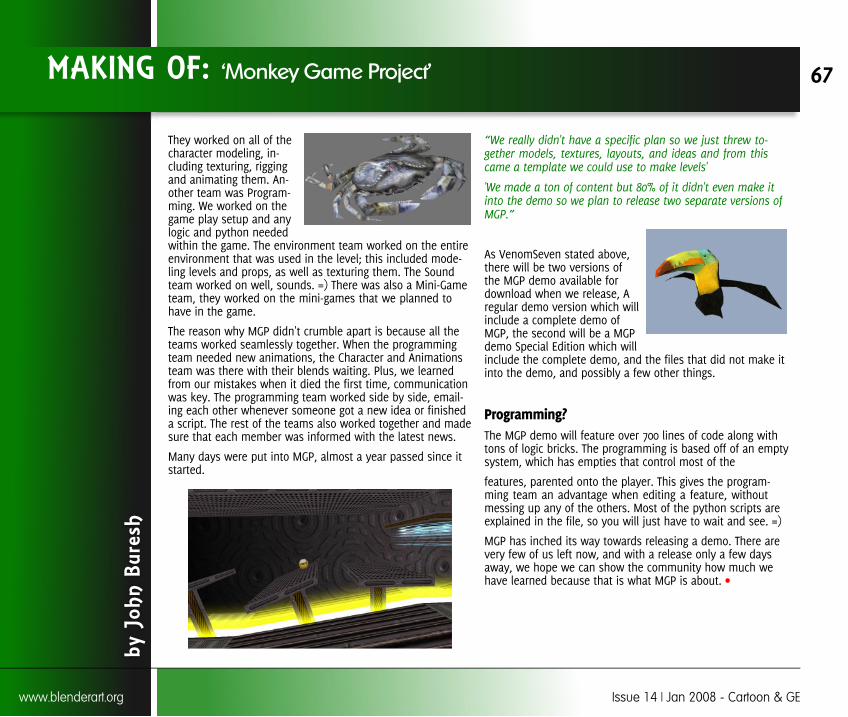
They worked on all of thecharacter modeling, in-cluding texturing, riggingand animating them. An-other team was Program-ming. We worked on thegame play setup and anylogic and python neededwithin the game. The environment team worked on the entireenvironment that was used in the level; this included mode-ling levels and props, as well as texturing them. The Soundteam worked on well, sounds. =) There was also a Mini-Gameteam, they worked on the mini-games that we planned tohave in the game.
The reason why MGP didn't crumble apart is because all theteams worked seamlessly together. When the programmingteam needed new animations, the Character and Animationsteam was there with their blends waiting. Plus, we learnedfrom our mistakes when it died the first time, communicationwas key. The programming team worked side by side, email-ing each other whenever someone got a new idea or finisheda script. The rest of the teams also worked together and madesure that each member was informed with the latest news.
Many days were put into MGP, almost a year passed since itstarted.
“We really didn't have a specific plan so we just threw to-gether models, textures, layouts, and ideas and from thiscame a template we could use to make levels'
'We made a ton of content but 80% of it didn't even make itinto the demo so we plan to release two separate versions ofMGP.”
As VenomSeven stated above,there will be two versions ofthe MGP demo available fordownload when we release, Aregular demo version which willinclude a complete demo ofMGP, the second will be a MGPdemo Special Edition which willinclude the complete demo, and the files that did not make itinto the demo, and possibly a few other things.
Programming?The MGP demo will feature over 700 lines of code along withtons of logic bricks. The programming is based off of an emptysystem, which has empties that control most of the
features, parented onto the player. This gives the program-ming team an advantage when editing a feature, withoutmessing up any of the others. Most of the python scripts areexplained in the file, so you will just have to wait and see. =)
MGP has inched its way towards releasing a demo. There arevery few of us left now, and with a release only a few daysaway, we hope we can show the community how much wehave learned because that is what MGP is about.
MAKING OF: ‘Monkey Game Project’
by J
ohn
Bure
sh
67
www.blenderart.org Issue 14 | Jan 2008 - Cartoon & GE
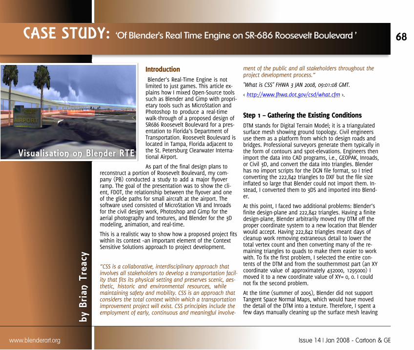
Introduction Blender’s Real-Time Engine is notlimited to just games. This article ex-plains how I mixed Open-Source toolssuch as Blender and Gimp with propri-etary tools such as MicroStation andPhotoshop to produce a real-timewalk-through of a proposed design ofSR686 Roosevelt Boulevard for a pres-entation to Florida’s Department ofTransportation. Roosevelt Boulevard islocated in Tampa, Florida adjacent tothe St. Petersburg Clearwater Interna-tional Airport.
As part of the final design plans toreconstruct a portion of Roosevelt Boulevard, my com-pany (PB) conducted a study to add a major flyoverramp. The goal of the presentation was to show the cli-ent, FDOT, the relationship between the flyover and oneof the glide paths for small aircraft at the airport. Thesoftware used consisted of MicroStation V8 and Inroadsfor the civil design work, Photoshop and Gimp for theaerial photography and textures, and Blender for the 3Dmodeling, animation, and real-time.
This is a realistic way to show how a proposed project fitswithin its context –an important element of the ContextSensitive Solutions approach to project development.
“CSS is a collaborative, interdisciplinary approach thatinvolves all stakeholders to develop a transportation facil-ity that fits its physical setting and preserves scenic, aes-thetic, historic and environmental resources, whilemaintaining safety and mobility. CSS is an approach thatconsiders the total context within which a transportationimprovement project will exist. CSS principles include theemployment of early, continuous and meaningful involve-
ment of the public and all stakeholders throughout theproject development process.”
"What is CSS" FHWA 3 JAN 2008, 09:01:08 GMT.
< http://www.fhwa.dot.gov/csd/what.cfm >.
Step 1 – Gathering the Existing ConditionsDTM stands for Digital Terrain Model; it is a triangulatedsurface mesh showing ground topology. Civil engineersuse them as a platform from which to design roads andbridges. Professional surveyors generate them typically inthe form of contours and spot-elevations. Engineers thenimport the data into CAD programs, i.e., GEOPAK, Inroads,or Civil 3D, and convert the data into triangles. Blenderhas no import scripts for the DGN file format, so I triedconverting the 222,842 triangles to DXF but the file sizeinflated so large that Blender could not import them. In-stead, I converted them to 3DS and imported into Blend-er.
At this point, I faced two additional problems: Blender’sfinite design-plane and 222,842 triangles. Having a finitedesign-plane, Blender arbitrarily moved my DTM off theproper coordinate system to a new location that Blenderwould accept. Having 222,842 triangles meant days ofcleanup work removing extraneous detail to lower thetotal vertex count and then converting many of the re-maining triangles to quads to make them easier to workwith. To fix the first problem, I selected the entire con-tents of the DTM and from the southernmost part (an XYcoordinate value of approximately 432000, 1295000) Imoved it to a new coordinate value of XY= 0, 0. I couldnot fix the second problem.
At the time (summer of 2005), Blender did not supportTangent Space Normal Maps, which would have movedthe detail of the DTM into a texture. Therefore, I spent afew days manually cleaning up the surface mesh leaving
CASE STUDY: ‘Of Blender’s Real Time Engine on SR-686 Roosevelt Boulevard ’
Visualisation on Blender RTE
by B
rian
Trea
cy
68
www.blenderart.org Issue 14 | Jan 2008 - Cartoon & GE
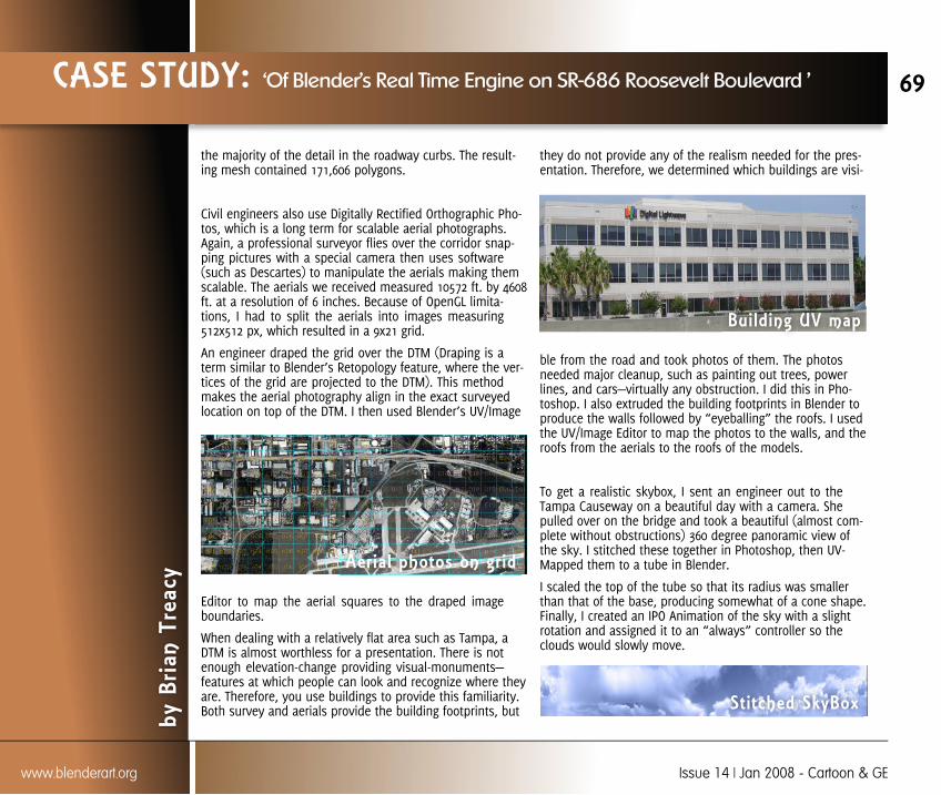
the majority of the detail in the roadway curbs. The result-ing mesh contained 171,606 polygons.
Civil engineers also use Digitally Rectified Orthographic Pho-tos, which is a long term for scalable aerial photographs.Again, a professional surveyor flies over the corridor snap-ping pictures with a special camera then uses software(such as Descartes) to manipulate the aerials making themscalable. The aerials we received measured 10572 ft. by 4608ft. at a resolution of 6 inches. Because of OpenGL limita-tions, I had to split the aerials into images measuring512x512 px, which resulted in a 9x21 grid.
An engineer draped the grid over the DTM (Draping is aterm similar to Blender’s Retopology feature, where the ver-tices of the grid are projected to the DTM). This methodmakes the aerial photography align in the exact surveyedlocation on top of the DTM. I then used Blender’s UV/Image
Editor to map the aerial squares to the draped imageboundaries.
When dealing with a relatively flat area such as Tampa, aDTM is almost worthless for a presentation. There is notenough elevation-change providing visual-monuments—features at which people can look and recognize where theyare. Therefore, you use buildings to provide this familiarity.Both survey and aerials provide the building footprints, but
they do not provide any of the realism needed for the pres-entation. Therefore, we determined which buildings are visi-
ble from the road and took photos of them. The photosneeded major cleanup, such as painting out trees, powerlines, and cars—virtually any obstruction. I did this in Pho-toshop. I also extruded the building footprints in Blender toproduce the walls followed by “eyeballing” the roofs. I usedthe UV/Image Editor to map the photos to the walls, and theroofs from the aerials to the roofs of the models.
To get a realistic skybox, I sent an engineer out to theTampa Causeway on a beautiful day with a camera. Shepulled over on the bridge and took a beautiful (almost com-plete without obstructions) 360 degree panoramic view ofthe sky. I stitched these together in Photoshop, then UV-Mapped them to a tube in Blender.
I scaled the top of the tube so that its radius was smallerthan that of the base, producing somewhat of a cone shape.Finally, I created an IPO Animation of the sky with a slightrotation and assigned it to an “always” controller so theclouds would slowly move.
CASE STUDY: ‘Of Blender’s Real Time Engine on SR-686 Roosevelt Boulevard ’
by B
rian
Trea
cy
69
www.blenderart.org Issue 14 | Jan 2008 - Cartoon & GE
Aerial photos on grid
Bui lding UV map
Stitched SkyBox

Step 2 – Building the Proposed Design
To design a road, the engineer produces several types ofelements: the horizontal alignment; the vertical alignment;typical sections; and cross sections. The horizontal align-ment is a 2D curve depicting the pathway that the road,ramp, or bridge will follow. The vertical alignment (alsoknown as a profile) is similar in function except it only pro-vides the elevation differences. The typical section gives ageneral representation of what a cut-through of the roadwould look like, while a cross section gives an exact repre-sentation of a cut at an exact location. A standard projectrequires this for each road, ramp, and bridge.
I combined the horizontal and vertical alignments in Micro-Station to produce one 3D alignment and imported it intoBlender. Following the same workflow as used with theDTM, I moved the data in MicroStation first to address thecoordinates and saved it to 3DS before importing. Once inBlender, I traced it using a 3D Bezier Curve. I then combinedsome of the typical sections and cross sections to formtwenty-eight specific segments of six different roads, ramps,and bridges. I imported these into Blender and traced them
as curves. Finally, I extruded the typical sections along thecurves to produce the 3D models.
In roadway terminology, a gore is an area of transitionwhere two or more roads converge or diverge. Due to eleva-tion differences and adherence to design criteria, designinga gore in 3D is a challenge, especially when you want tomake it usable in Blender’s Real-Time engine. Essentially, Imanually smoothed the meshes where the ramps joined thearterial roads and where the roads intersected. In retro-spect, this was probably the most difficult task.
Designing the bridge for the flyover was very simple andsimilar to the roads and other ramps. I extruded the typicalsections along the 3D curve to create the superstructure andmanually modeled the hammerhead piers, approaches, andabutments within Blender.
CASE STUDY: ‘Of Blender’s Real Time Engine on SR-686 Roosevelt Boulevard ’
by B
rian
Trea
cy
70
www.blenderart.org Issue 14 | Jan 2008 - Cartoon & GE
Typical section of road & pier
Extruded models
Flyover & Piers
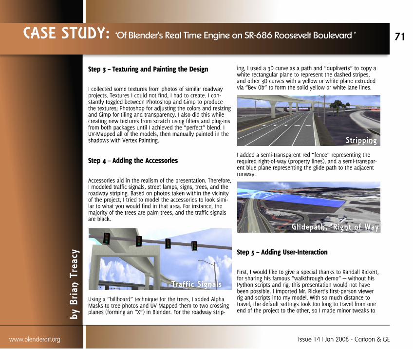
Step 3 – Texturing and Painting the Design
I collected some textures from photos of similar roadwayprojects. Textures I could not find, I had to create. I con-stantly toggled between Photoshop and Gimp to producethe textures; Photoshop for adjusting the colors and resizingand Gimp for tiling and transparency. I also did this whilecreating new textures from scratch using filters and plug-insfrom both packages until I achieved the “perfect” blend. IUV-Mapped all of the models, then manually painted in theshadows with Vertex Painting.
Step 4 – Adding the Accessories
Accessories aid in the realism of the presentation. Therefore,I modeled traffic signals, street lamps, signs, trees, and theroadway striping. Based on photos taken within the vicinityof the project, I tried to model the accessories to look simi-lar to what you would find in that area. For instance, themajority of the trees are palm trees, and the traffic signalsare black.
Using a “billboard” technique for the trees, I added AlphaMasks to tree photos and UV-Mapped them to two crossingplanes (forming an “X”) in Blender. For the roadway strip-
ing, I used a 3D curve as a path and “dupliverts” to copy awhite rectangular plane to represent the dashed stripes,and other 3D curves with a yellow or white plane extrudedvia “Bev Ob” to form the solid yellow or white lane lines.
I added a semi-transparent red “fence” representing therequired right-of-way (property lines), and a semi-transpar-ent blue plane representing the glide path to the adjacentrunway.
Step 5 – Adding User-Interaction
First, I would like to give a special thanks to Randall Rickert,for sharing his famous “walkthrough demo” — without hisPython scripts and rig, this presentation would not havebeen possible. I imported Mr. Rickert’s first-person viewerrig and scripts into my model. With so much distance totravel, the default settings took too long to travel from oneend of the project to the other, so I made minor tweaks to
CASE STUDY: ‘Of Blender’s Real Time Engine on SR-686 Roosevelt Boulevard ’
by B
rian
Trea
cy
71
www.blenderart.org Issue 14 | Jan 2008 - Cartoon & GE
Traff ic Signals
Gl idepath, ‘Right of Way’
Str ipping
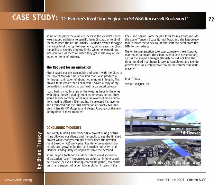
some of the property values to increase the viewer’s speed.Next I added collisions to specific faces (instead of to all ofthem) to keep the FPS up. Finally, I added a switch to togglethe visibility of the right-of-way fence, which gave the Clientthe ability to see his property limits when he wanted, butwas able to turn them off when they got in the way of see-ing other items of interest.
The Request for an AnimationAfter I saved out the executable and sent it with the DLL’s tothe Project Manager, he requested that I also produce afly-through animation of about two minutes in length. Thisproved to be easier than I expected. I saved a copy of mypresentation and added a path with a parented camera.
I also had to modify a few of the textures (mostly the oneswith alpha masks), adding them as materials so that theywould render correctly. After several low-resolution anima-tions testing different flight paths, he selected his favorite,and I rendered out the final animation at exactly two min-utes in length. UV Mapping and Vertex Painting cut the ren-dering time to mere minutes!
CONCLUDING THOUGHTSAccurately building and rendering a project during design(thus allowing our clients and the public to see the finishedproject while changes can still occur) aided the develop-ment based on CSS principles. Real-time presentation de-mands are growing in the construction industry, andBlender is adequately equipped to serve the demand.
Some helpful tools for Blender’s future could include aMicroStation “.dgn” import/export script, an infinite coordi-nate plane (or even a floating coordinate plane), real-worldunits, and support of large high-resolution images in the
Real-Time engine. Some helpful tools for my future includethe use of Tangent Space Normal Maps and the Retopologytool to lower the vertex count and shift the detail from theDTM to the textures.
The entire presentation took approximately three hundredman-hours to create. The client loved it (the presentation),as did the Project Manager (though he did not love thethree-hundred man-hours it took to complete), and Blenderproved itself as a competitive tool in the commercial work-place.
Brian Treacy
Senior Designer, PB
CASE STUDY: ‘Of Blender’s Real Time Engine on SR-686 Roosevelt Boulevard ’
by B
rian
Trea
cy
72
www.blenderart.org Issue 14 | Jan 2008 - Cartoon & GE
Glidepath, ‘Right of Way’
3d Flyover

In this article you can learn how to use web serviceswith Blender to make games or walk-throughs that areable to interact with resources on the Internet. I'llassume that you have some background of XML, Py-thon, and PHP.
Bellow you can read my interview with Mr: Blender.
Me: Hello Mr: Blender!
Hey YOU!
Me: - I'm thinking about making a game or walk-through that interacts with others on the Internet.
OK, what's the problem? You can do itusing python scripting.
Me: Yes I know that I can do it, but... I don't knowhow!
Do you know about web services?
Me: Web services?!
Yes. It's about exchanging data betweena web server and a client.
Me: Hmmm. Can you explain more about web servic-es?
Web services are methods you write orsee in programs. Both are called with local programs,
but the difference is that methods in local programsrun locally and use local system resources, whilemethods in web services run on servers and useserver resources. This isn't a complete definition of aweb service, but it's close enough.
Me: Can you give me some examples of using a webservice in Blender?
Okay. For example, you might want:
Users of your game to register on your web site andthen login into the game using their user name andpassword (you can see this in almost all onlinegames)
Your game to check for a newer version when start-ing and prompts the user to update
To make a 3D presentation of a house for sale andusers can chat with the house owner and askhim/her some questions, or many other examples.
Me: Oh, well, I think that when users must registertheir user name and password, I should have a data-base that contains user data, but what is the relationbetween Blender, Python, Web Service, and a Data-base?
Have a look at the following picture; Ithink that it will help you find the answer.
INTERVIEW: ‘Mr. Blender’s Web Services ’
Interview with Mr. Blender!on Using Web Services in Blender
By -
Ham
ed Z
agha
ghi
73
www.blenderart.org Issue 14 | Jan 2008 - Cartoon & GE
Blender! & Web Services

Me: OK, can you go step by step to make a complete exam-ple?
Yes. Let's make a game with version checker,step by step.
Me: OK. :)
First of all we need a game. You can use yourprevious games, or make a simple game, or simply use thestandard Blender scene with a cube at the center as a gameand continue.
Me: OK, I'll use a new Blender scene.
First we add an Always sensor, and uncheckboth True and False pulse mode.
Me: Ok.
Now make a new file in the Text Editor andname it "check_version" without quotes, then add a Pythoncontroller and set Script parameter to "check_version" with-out quotes again, then connect the Always Sensor to thePython Controller.
Me: And then?
Before doing anything else in Blender, we needto configure our web service server. I use Apache as myweb server, PHP for writing web services, the XML-RPC pro-tocol for my web service, and Keith Devens' implementationof XML-RPC on PHP. You can find XML-RPC implementationsin other programming languages athttp://www.xmlrpc.com/directory/1568/implementations
Me: Oh, and then?
For setting the web service up, first downloadKeith Devens' implementation fromhttp://www.keithdevens.com/software/xmlrpc/source, thenupload it somewhere to your web server.
Me: OK, I'm downloading it and uploading tohttp://en.blender.ir/webservices.
Then write this code in a text editor and save itas a php file in the same directory that you uploaded theXML-RPC implementation. Let's call it server.php.
<?php
#1)Include Keith Devens implementation
include("kd_xmlrpc.php");
#2)Web Service Methods
$xmlrpc_methods = array();
$xmlrpc_methods['CurrentVersion'] = 'getCurrentVersion';
$xmlrpc_methods['method_not_found'] ='XMLRPC_method_not_found';
INTERVIEW: ‘Mr. Blender’s Web Services ’
By -
Ham
ed Z
agha
ghi
74
www.blenderart.org Issue 14 | Jan 2008 - Cartoon & GE
Adding Always Sensor
Adding Python Controller
#3)Web Service Server
$xmlrpc_request = XMLRPC_parse($HTTP_RAW_POST_DATA);
$methodName =XMLRPC_getMethodName($xmlrpc_request);
$params = XMLRPC_getParams($xmlrpc_request);
if(!isset($xmlrpc_methods[$methodName])){
$xmlrpc_methods['method_not_found']($methodName);
}else{
$xmlrpc_methods[$methodName]($params);
}
#4)Web Service Methods Implementation
function getCurrentVersion($params){
$returnversion['version'] = 3.60;
$returnversion['minor']=60;
$returnversion['major']=3;
XMLRPC_response(XMLRPC_prepare($returnversion));
}
function XMLRPC_method_not_found($methodName){
XMLRPC_error("2", "The method you requested,'$methodName', was not found.");
}
?>
Me: I can do it, but I don't know what the code is for.
This code setups an XML-RPC server usingKeith Devens' implementation, with two methods,"getCurrentVersion" and "method_not_found." The firstmethod is the one we want to call from blender, and thesecond one is for requested methods that this server
doesn't support. In the first section of code we include theXML_RPC implementation, and in the second section wesetup an array that is used with the server code to find animplementation of the requested method. For examplewhen in line 2 section 2, we say that if a method named"CurrentVersion" exists, the requested server should run the"getCurrentVersion" method implemented in section 4.
Then, in the third section, parse the request and extract therequested method name and its parameters. Finally, checkif the requested method name was implemented, and ifnot, run "method_not_found" instead.
Me: Oh. I think that after we write this code and save it onserver.php, we can then send a request method name andits parameters to server.php, and this code will run the re-quested method and respond with its value.
Yes, that's right. As a short explanation, the"getCurrentVersion" method responds with a structure ofthree fields - version, minor and major. Every time my pro-gram gets updated we change those numbers. In thesemethods, we can connect to databases and get some infor-mation from them.
Me: And then from python send a request to server.php torun getCurrentVersion. But how can we do it in python?
This section is easier than the previous one.Python has a library named "xmlrpclib," and we can use itto send requests and receive responses. To see what thislibrary can do, paste this code in the python text editor ofBlender, then press P.
import xmlrpclib
this_version = 1.3
server =xmlrpclib.Server("http://en.blender.ir/webservices/server.php")
INTERVIEW: ‘Mr. Blender’s Web Services ’
By -
Ham
ed Z
agha
ghi
75
www.blenderart.org Issue 14 | Jan 2008 - Cartoon & GE

current_version = server.getCurrentVersion()
if(current_version['version'] > this_version):
print "Go to program web site and download updatedversion."
else:
print "program is updated."
Me: I'll do it, but where I can see the results?
You can see the printed line in theterminal/command prompt of blender.
Me: Thank you, Mr. Blender, for your time.
You're welcome!
Interviewer - Hamed Zaghaghi,
MSc. Student of Algorithms and Computation,
Engineering Science Department, University of Tehran
Email - [email protected]
INTERVIEW: ‘Mr. Blender’s Web Services ’
By -
Ham
ed Z
agha
ghi
76
www.blenderart.org Issue 14 | Jan 2008 - Cartoon & GE

www.blenderart.org Issue 14 | Jan 2008 - Cartoon & GE
Maciej Sankowski (sanki) - CMYK ToucanGALLERIA
77

www.blenderart.org Issue 14 | Jan 2008 - Cartoon & GE
Salvador Gracia Bernal - Sad LoveGALLERIA
78
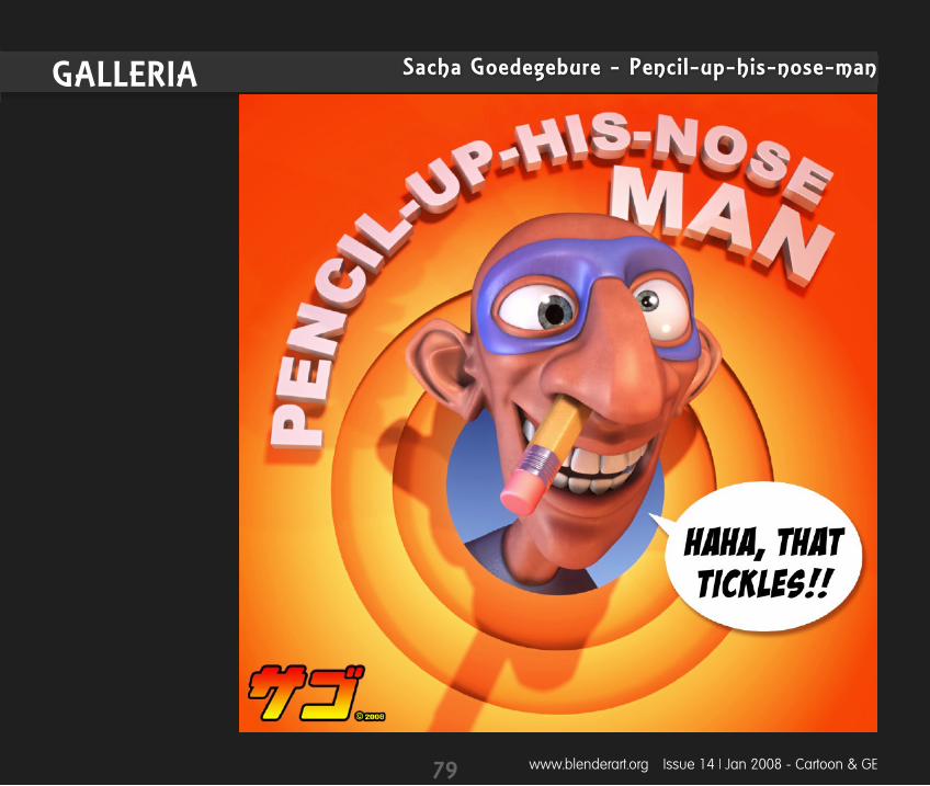
www.blenderart.org Issue 14 | Jan 2008 - Cartoon & GE
Sacha Goedegebure - Pencil-up-his-nose-manGALLERIA
79
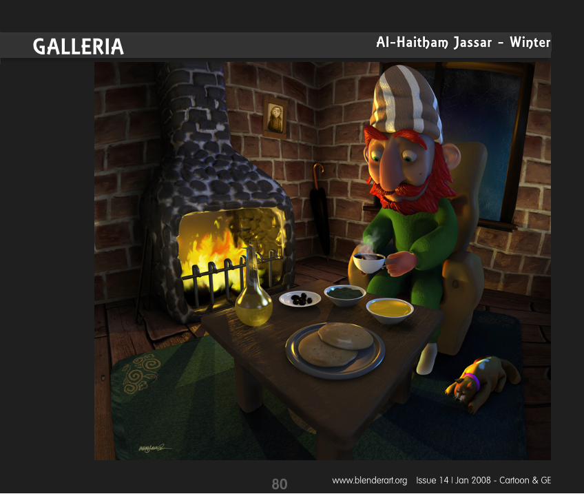
www.blenderart.org Issue 14 | Jan 2008 - Cartoon & GE
Al-Haitham Jassar - WinterGALLERIA
80
www.blenderart.org Issue 14 | Jan 2008 - Cartoon & GE
Cristian Mihaescu - Night of the deadGALLERIA
81
www.blenderart.org Issue 14 | Jan 2008 - Cartoon & GE
Cristian Mihaescu - OwnerGALLERIA
82

www.blenderart.org Issue 14 | Jan 2008 - Cartoon & GE
Adr Kiritschenko - EetGALLERIA
83

www.blenderart.org Issue 14 | Jan 2008 - Cartoon & GE
RobertT - And for your final wishGALLERIA
84
www.blenderart.org Issue 14 | Jan 2008 - Cartoon & GE
Emanoel Castro - Cabeca ToledoGALLERIA
85

www.blenderart.org Issue 14 | Jan 2008 - Cartoon & GE
Bruce Parrott - A GiftGALLERIA
86
www.blenderart.org Issue 14 | Jan 2008 - Cartoon & GE
John Siar (geartrooper) - Grenade LauncherGALLERIA
87
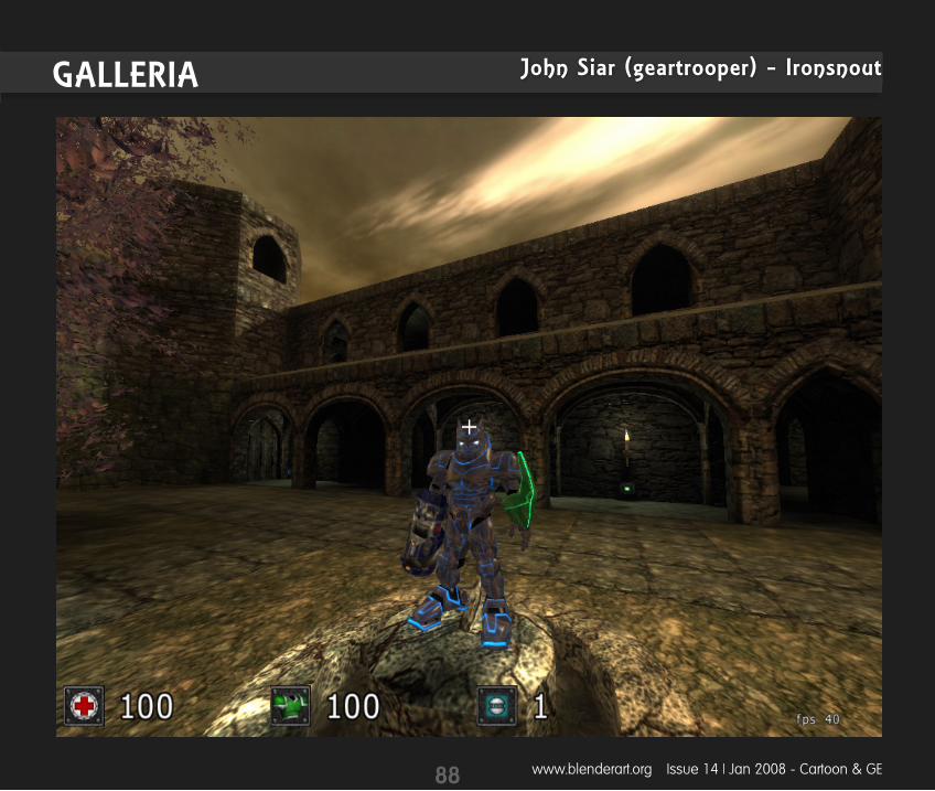
www.blenderart.org Issue 14 | Jan 2008 - Cartoon & GE
John Siar (geartrooper) - IronsnoutGALLERIA
88

1. We accept the following: Tutorials explaining new Blender features, 3dconcepts, techniques or articles based on currenttheme of the magazine.
Reports on useful Blender events throughout the world. Cartoons related to blender world.
2. Send submissions to [email protected]. Send us a notification onwhat you want to write and we can follow up from there. (Some guidelinesyou must follow)
Images are preferred in PNG but good quality JPG can also do. Images should be separate fromthe text document.
Make sure that screenshots are clear and readable and the renders should be at least 800px,but not more than 1600px at maximum.
Sequential naming of images like, image 001.png... etc. Text should be in either ODT, DOC, TXT or HTML. Archive them using 7zip or RAR or less preferably zip.
3. Please include the following in your email: Name: This can be your full name or blenderartist avtar. Photograph: As PNG and maximum width of 256Px. (Only if submitting the article for the firsttime )
About yourself: Max 25 words . Website: (optional)
Note: All the approved submissions can be placed in the final issue or subsequent issue ifdeemed fit. All submissions will be cropped/modified if necessary. For more details see the blend-erart website.
89
www.blenderart.org Issue 14 | Jan 2008 - Cartoon & GE
Want to write for BlenderArt Magazine?
Here is how!
blenderart.org does not takes any responsibility both expressed or implied for the material and itsnature or accuracy of the information which is published in this PDF magazine. All the materialspresented in this PDF magazine have been produced with the expressed permission of their re-spective authors/owners. blenderart.org and the contributors disclaim all warranties, expressed orimplied, including, but not limited to implied warranties of merchantability or fitness for a particu-lar purpose. All images and materials present in this document are printed/re-printed with ex-pressed permission from the authors/owners.This PDF magazine is archived and available from the blenderart.org website. The blenderart maga-zine is made available under Creative Commons‘ Attribution-NoDerivs 2.5’ license.
COPYRIGHT© 2007‘BlenderArt Magazine’, ‘blenderart’ and BlenderArt logo are copyright of Gaurav Nawani. ‘Izzy’ and‘Izzy logo’ are copyright Sandra Gilbert. All products and company names featured in the publica-tion are trademark or registered trade marks of their respective owners.
90
www.blenderart.org Issue 14 | Jan 2008 - Cartoon & GE
Upcoming Issue ‘Theme’
Issue 15
Disclaimer
Animation Recent improvements in animation tools Facial animation: emotions, lip syncing, phenomes Making you animation more believable: arcs, follow through, secondary actions Free characters and character rigs etc.