blofeld eng v2 - waldorf music · pdf fileforeword blofeld user´s manual 2 foreword...
TRANSCRIPT


Foreword
Blofeld User´s Manual 2
Foreword Thank you for purchasing the Waldorf Blofeld. You now own a synthesizer featuring a wide range of unique sounds with the approved Waldorf quality.
What to read? The biggest problem with any manual is to find a way to cover both the needs of an absolute expert and a beginner alike. There are people who read a manual cover to cover while others don’t even touch it. The latter is the worst choice, especially when the manual describes a Waldorf instrument.
If you decide to read the following manual we promise you a lot of fun while reading about and working with the Waldorf Blofeld.
Your Waldorf Team
Hint Waldorf Music is not liable for any erroneous information contained in this manual. The contents of this manual may be updated at any time without prior notice. We made every effort to ensure the information herein is accurate and that the manual contains no contradictory information. Waldorf Music extends no liabilities in regard to this manual other than those required by local law.
This manual or any portion of it may not be reproduced in any form without the manufacturer's written consent.
Waldorf Music GmbH, Neustrasse 12, D-53498 Waldorf, Germany

Foreword
3 Blofeld User´s Manual
Blofeld Development Team Software: Stefan Stenzel, Wolfram Franke
Hardware/ Housing: Frank Schneider
Design: Axel Hartmann
Manual/ Layout: Holger Steinbrink
Betatest/ Sounddesign: Wolfram Franke, Boele Gerkes, Achim Gratz, Till Kopper, Jahnspierr Leyton, Dr. Georg Müller, Don Petersen, Howard Scarr, Holger Steinbrink, Sascha Timm, Dr. Stefan Trippler
Revision: 1.1, January 2009
w Please visit our website www.waldorfmusic.de Maybe you can download a newer operating system for your Blofeld.
We would like to thank Willie Eckl, Joachim Flor, Michael von Garnier, Florian Gypser, Frank Lauterbach, Achim Lenzgen, Kurt “Lu” Wangard, 吴海彬 and anyone we have forgotten.
Content
Blofeld User´s Manual 4
Content Foreword ............................................................................................ 2 What to read?.................................................................. 2
Hint ................................................................................ 2
Blofeld Development Team............................................. 3
We would like to thank................................................... 3
Content................................................................................................ 4
Control Features and Connections ................................................ 7 Front Panel Blofeld Desktop............................................ 7
Connections Blofeld Desktop .......................................... 8
Front Panel Blofeld Keyboard.......................................... 9
Connections Blofeld Keyboard ...................................... 10
Introduction...................................................................................... 11 About this Manual......................................................... 11 Symbols ........................................................................ 11 Highlighted Control Features and Parameters................ 11
General Safety Guidelines............................................. 12 Suitable Operating Conditions ...................................... 12 Power Supply................................................................ 12 Operation ..................................................................... 12
Maintenance..................................................................13 Proper Use.....................................................................13
Setup and Connection ....................................................................14 Inventory .......................................................................14
Setup .............................................................................14
Connections ..................................................................14
The USB connection......................................................15
The Blofeld Keyboard Controls ......................................16
Basic Operation ................................................................................18 Switching on/ off............................................................18
System Volume..............................................................18
Selecting Programs ........................................................18 Fast Selection of Sound Banks........................................18
Category Search.............................................................19
Editing Parameters .........................................................19 Editing Parameter Controls.............................................20 Viewing Parameter Values without Change ...................21 Comparing Edited Programs...........................................21 Recalling Edited Programs .............................................22 Storing Programs............................................................22
Multi Mode.........................................................................................24 Multimode Parameter ....................................................24

Content
5 Blofeld User´s Manual
Multi Part Parameter...................................................... 24
Menu Pages Overview .....................................................................29
Sound Parameters ...........................................................................35 Overview of Functions .................................................. 35
Oscillator Section.......................................................... 35 Oscillator Parameter Controls........................................ 36 Oscillator Edit Menu ..................................................... 38
Oscillator 1, 2 and 3 ..................................................... 38
Oscillator Common....................................................... 43 Ringmodulation............................................................. 45 Noise ............................................................................ 46
The Filter Section .......................................................... 47 Filter Section Parameter Controls................................... 47 Filter Edit Menu............................................................. 50
Filter 1 and 2................................................................. 50 Filter Common .............................................................. 52
Modulation Section ....................................................... 53 Parameter Controls of the Filter and Amp Envelope....... 53
Envelopes Edit Menu ..................................................... 54 LFO Parameter Controls ................................................ 57 LFO Edit Menu .............................................................. 58 LFO 1, 2 and 3 .............................................................. 58
Modulation Matrix Parameter Controls ..........................60 Modulation Matrix Edit Menu ........................................61 Modifier.........................................................................61
Amplifier Edit Menu.......................................................63 Effects Parameter Controls..............................................64 Effects Edit Menu ...........................................................64 Effect Bypass ..................................................................64 Chorus ...........................................................................65 Flanger ..........................................................................65 Phaser............................................................................66 Overdrive ......................................................................66 Triple FX........................................................................67 Delay.............................................................................68 Clk. (Clocked) Delay......................................................69 Reverb ...........................................................................70
Arpeggiator ....................................................................72 Arpeggiator Parameter Controls .....................................72 Arpeggiator Step Data Pages ..........................................77
Global Parameters............................................................................81 Global Menu .................................................................81 Utility Menu ..................................................................86 Store Sound Functions ...................................................86 Help Functions ..............................................................86 MIDI Dump Functions ...................................................86

Content
Blofeld User´s Manual 6
Receiving System Exclusive Data .................................. 87
Sound Synthesis Basics................................................................. 89 Oscillators Introduction................................................. 89
Filter Introduction ......................................................... 96
The Comb Filter Types .................................................. 98
Envelope Types ........................................................... 103
Appendix......................................................................................... 106 FM Sources ................................................................. 106
Modulation Sources .................................................... 106
Modulation Destinations ............................................. 107
Updating the System Software .....................................109
Tips & Tricks................................................................111
Technical Data ............................................................112
Controller Numbers .....................................................113
Glossary ......................................................................118
Declaration of Conformity ...........................................124
FCC Information ..........................................................126
Product Warranty ........................................................127
Product Support...........................................................127

Control Features and Connections
7 Blofeld User´s Manual
Control Features and ConnectionsFront Panel Blofeld Desktop
a Display
b Parameter Matrix
c Selection Dial with Play button
d System Volume Dial
e Display Parameter Dials
! "
#
$
%

Control Features and Connections
Blofeld User´s Manual 8
Connections Blofeld Desktop
A Power supply socket
B MIDI In jack
C USB port for connection to a suited computer
D Stereo audio output left/right (only left: mono, only rights: stereo)
E Stereo Headphone jack
6 Power switch
!"#$ %&

Control Features and Connections
9 Blofeld User´s Manual
Front Panel Blofeld Keyboard
a Display
b Parameter Matrix
c Selection Dial with Play button
d System Volume Dial
e Display Parameter Dials
f Pitch Bend Wheel and Modulation Wheel
g Octave Up and Down Button
h Free Button

Control Features and Connections
Blofeld User´s Manual 10
Connections Blofeld Keyboard
A Power supply socket
B MIDI In jack
C USB port for connection to a suited computer
D Stereo audio output left/right (only left: mono, only rights: stereo)
E Stereo Headphone jack
6 Power switch
7 MIDI Out jack
8 Pedal input

Introduction
11 Blofeld User´s Manual
Introduction About this Manual This manual was written to help you to become familiar with the Blofeld synthesizer. It will also aid experienced users with routine tasks.
To avoid confusion, the terminology in this manual is based on the Blofeld parameter names. You will find a glossary at the end of this manual; it explains the various terms used.
We also used a uniform set of symbols to show you topics of particular interest or significance. Important terms are highlighted in bold letters.
Symbols
m Caution – The comments that follow this symbol will help you avoid errors and malfunctions.
w Info – Additional information on a given topic.
☞ Instruction – Follow these guidelines to execute a desired function.
✻ Example – Real-world examples to try out.
Highlighted Control Features and Parameters All of the Blofeld´s buttons, controls and parameters are highlighted in bold letters throughout the manual. Example:
Example:
• Press the Play button.
The Blofeld’s different modes and parameter pages are illustrated in a depiction of the display.
The value range of a continuous parameter is indicated from low to high with both values shown in italic letters, separated by three dots.
Example:
Cutoff 0…127

Introduction
Blofeld User´s Manual 12
General Safety Guidelines
m Please read the following safety tips carefully! They include several precautions you should always observe when dealing with electronic equipment. Read all of the instructions before operating your device.
Suitable Operating Conditions • Use the device in enclosed rooms only.
• Never use the device under damp conditions such as in bathrooms, washrooms or around indoor swimming pools.
• Do not use the device in extremely dusty or dirty environments.
• Make sure that adequate ventilation is available at all sides of the device.
• Do not place the device near heat sources such as radiators.
• Do not expose the device to direct sunlight.
• Do not expose the device to extreme vibrations.
Power Supply • Never use a different power cable than the one that
came with the Blofeld.
• Unplug the device when you are not using it for longer periods.
• Never touch the plug with wet hands.
• Always pull the plug when unplugging the device, never the cable.
Operation • Never place objects containing liquids on or near
the device.
• Place the device on a stable base only. Use a suitable platform.
• Make sure no foreign objects find their way into the chassis. If for some reason this should occur, switch the power off, unplug the device and consult a qualified repair center.
• This device, used on its own or with amplifiers, speakers or headphones, can generate volume levels that may do irreparable damage to your hearing. For

Introduction
13 Blofeld User´s Manual
this reason you should keep the volume at tolerable levels.
Maintenance • Do not open the device or remove the cover. Refer
all service and repair tasks to qualified personnel. The interior of the chassis contains no components that require user maintenance.
• Use only a dry, soft cloth or brush to clean the device. Never use alcohol, cleaning solutions or similar chemicals. They will damage the surface of the chassis.
Proper Use This device is designed exclusively to produce low-frequency audio signals for the purpose of generating sound. Any other use is prohibited and voids the warranty extended by Waldorf Music. Waldorf Music is not liable for damages due to incorrect use.
m Don´t let your Blofeld beside children, mothers-in-law or pets. This could lead to critical interactions.

Setup and Connection
Blofeld User´s Manual 14
Setup and Connection Inventory The Waldorf Blofeld comes complete with:
• the Waldorf Blofeld (Keyboard) Synthesizer
• an external power supply or a power cable (Keyboard version)
• a CD-ROM with the complete PDF manual and other tools
• a printed Quick Start manual
Please ensure all the items above were included. If something is missing, contact your local dealer.
We recommend that you save the original packing material for future transport.
Setup Place the Blofeld on a clean, even surface.
Connections In order to get started with your Blofeld you will need an AC power outlet, a mixing console, an amp or/ and an audio monitor such as a speaker cabinet and last but not least a MIDI master keyboard for the Blofeld Desktop.
You can also use a computer or sequencer to make use of the Blofeld’s MIDI features.
☞ To connect the devices:
1. Turn all units off.
2. Connect the Blofeld´s main audio outputs 4 to your mixing console or your computer audio interface. Optionally connect the stereo headphone outputs 5 to a headphone.
3. To play the Blofeld you need a MIDI master keyboard. Connect its MIDI Out jack to the Blofeld´s MIDI input 2 (unless you connected a computer MIDI interface).
4. If you want to use a computer, connect your computer´s MIDI Out jack to the Blofeld´s MIDI In jack 2.
5. Optionally you can connect the Blofeld´s USB port 3 with a USB cable to your computer

Setup and Connection
15 Blofeld User´s Manual
(Windows PC or Apple Mac). After that the Blofeld is automatically available as a MIDI unit.
6. Connect the power supply cable or the power cable that came with the Blofeld with the Power supply 1 jack.
7. Plug the other side of the power supply cable into a suitable AC power outlet.
8. Press the power switch 6 of your Blofeld.
9. Then switch on the computer (if connected), the mixing console and finally the amplifier or active monitor speakers.
w To check the correct reception of MIDI Data send any MIDI Events to the Blofeld; the MIDI LED lights up on any incoming MIDI Message. If this is not the case please check the MIDI connection to the Blofeld.
w The Main volume of the Blofeld can be changed with the System Volume Dial d.
w If you do not choose to connect a mixing console, you can patch the Blofeld’s output signals directly to an amp or an audio interface. Use an input usually called Line, Aux or Tape input.
m Before connecting and disconnecting the Blofeld to a power supply source, turn your amp’s volume control all the way down to avoid damage due to on/off switching noise. The Blofeld produces a high level output signal. Please take care that the connected playback device is suitable for the high level of an electronic instrument. Never use the mic or phono input of the connected amp!
The USB connection You can connect the Blofeld with a USB cable to your computer with the following system requirements:
• Windows PC: Windows ME, Windows XP or newer is recommended, a USB 2 port
• Apple Mac: PowerPC or Intel Mac with Mac OS X 10.3.9 or newer, a USB 2 port
The USB 2 connection of the Blofeld allows
• transmitting and receiving of MIDI data
• dumping of operating system updates for the Blofeld
• data exchange with suitable computer software

Setup and Connection
Blofeld User´s Manual 16
w Keep in mind that you use a USB 2 port of your computer and a USB 2 suited cable to avoid problems with data transmission.
w Keep in mind that we offer new operation system updates from time to time. Please read also the chapter „Updating the System Software“. You can install a new operating system as well as MIDI or an USB connection.
The Blofeld Keyboard Controls
Keyboard You might have used a similar one before, but as it is rarely described elsewhere, this is how you use it:
Hit any black or white key to hear a sound. Usually the sound is louder when you play harder and less loud if you play softer. Also the pitch of the sounds are usually higher the more you play on the right side and lower on the left side. The white keys consist of notes from the C major scale, if you use another scale you will very likely have to use some of the black keys as well.
Pitch Bend Wheel Use this wheel to alter the pitch of the played notes. It will jump to the center position when you release it.
Modulation Wheel Use this wheel to alter the sound of the played notes. In contrast to the pitch bend wheel it does not go back to its default position on release. Don't worry if sometimes the sound id not changing, in this case a sloppy sound programmer forgot to assign it.
MIDI Out Jack Although we can hardly believe it, the Blofeld is not enough for some people, so we added an elegant way to control external sound modules with the Blofeld keyboard: Just connect MIDI out 7 to you external gear and play. For use with a computer we recommend the USB port.
Pedal Input An electrical sustain pedal switch connected to this input 8 enables you to sustain played notes as long as you press the pedal. As some pedals open contacts when pressed and others close, you can adopt Blofeld's

Setup and Connection
17 Blofeld User´s Manual
behaviour to this in the Global Menu. Please refer to the corresponding chapter.
Octave Down/Up Buttons Although the MIDI standard requires 128 keys, Blofeld offers only 49 of those. To compensate this limitation, we added these buttons g to enable you to reach more keys that physically accessible. Press Octave down to go one octave lower, and Octave up to go one octave higher. Transposition is maximum three octaves up and three octaves down
Free Button Just for fun we added an additional button h with assignable function. The functions are accessible from Global Menu. Please refer to the corresponding chapter.

Basic Operation
Blofeld User´s Manual 18
Basic Operation Switching on/ off The Blofeld ist equipped with a power switch.
☞ To switch the Blofeld on
• Flick the Power switch 6 to switch on the Blofeld. The display is lit.
☞ To switch the Blofeld off:
• Flick the Power switch 6 to switch off the Blofeld.
System Volume The System Volume d controls the Blofeld’s master volume. The volume setting is global and affects the level of the audio output 4 and the headphone output 5.
Selecting Programs Use the Selection dial c� to select the sound programs of the Blofeld.
☞ To select a Program with the Selection dial c:
• Make sure that the Play Sound mode is shown in the display a. If not, press the Play button c� shortly.
• Use the Selection dial c to select an appropriate Program. Turning the dial clockwise increases the Program number, turning the dial counterclockwise decreases it. When you are at the end of one Bank and turn the Selection dial further, you will jump to the beginning of the next Bank and vice versa. The only exceptions are the first Program in the first Bank (A001) and the last Program in the last Bank.
• The display shows the bank number first (A, B, C,...), after that program number (001 to 128) and then the name of the selected Program.
Fast Selection of Sound Banks In Play mode the Banks can be changed quickly by using the left Display parameter dial e. Turning the knob clockwise raises the bank number, turning counterwise lowers it.

Basic Operation
19 Blofeld User´s Manual
Category Search The Blofeld offers a special function to enable easy searches for sounds of similar categories. If you’re searching for pad sounds, only these sounds will be displayed as you scan the storage banks with the Selection dial. To accomplish this each sound contains 4 extra digits in the sound name to define its sound category. Further details about how to change a sound’s category are described in the chapter „Storing Programs“ on page 19.
☞ Searching for a special sound categroy:
1. Make sure that the Play Sound mode is shown in the display a. If not, press the Play button c� shortly.
2. Use the right Display parameter dial e to select the desired category (e.g. Bass).
3. Use the Selection dial c to scroll through the patches of the selected category.
☞ Switching off Category Search:
1. Use the right Display parameter dial e to select off.
w Category Search doesn’t change any program numbers. It only filters out all patches not belonging to the selected category. Scrolling through patches with this function is much faster because only patches belonging to the selected category are visible.
Editing Parameters In order to change or edit a program in the Blofeld, you must access the appropriate parameters. In spite of the Blofeld’s compactness it uses a sophisticated user interface allowing fast editing of any parameter. The change of any value is done with the so-called endless rotaries in the Parameter matrix b.
The rotary knobs control parameters with continuous values. All rotary controls consist of dials. Turning a dial clockwise increases the corresponding value; turning it counterclockwise decreases it. The dials have a built-in dynamic response feature. If you turn the control slowly, the value changes very smoothly, too. If you turn it faster, it accelerates as well. This gives you the chance of adjusting the whole value range in just one turn without losing accurate control when necessary. Bipolar parameters (parameters with positiv and negative values) use special gradation when changing their values. As soon

Basic Operation
Blofeld User´s Manual 20
as the value 0 is reached, the sweep is stopped for a short period to make it easier to edit the Blofeld.
Editing Parameter Controls
w We recommend to switch on the Auto Edit function in the Global menu. Read more on this on page 72.
The basic programming of the Blofeld is done via the so-called Parameter matrix f which has its most important parameters silkscreened on the machine´s front panel. Changing the parameters is done with the four endless rotaries on the bottom of the matrix. Changing the edit level is done with the four navigation buttons left to the parameter matrix and the two Display parameter dials e. This sounds more complex than it is. With a simple example you will understand the structure of the Blofeld handling easily.
Would you like to change the Cutoff of Filter 2? Please proceed as follows:
☞ To access a specific panel parameter:
1. Locate the section that contains the desired parameter on the front panel. For example, if you want to change Cutoff of Filter 2, refer to the Filter section. To do this please press the filter
section button until the LED for Filter 2 lights up in the Filter section.
2. With the first endless rotary you can now change the Cutoff parameter of Filter 2.
3. Whenever you change a parameter by moving a knob, the display shows the edited parameter and its current value in the upper right corner for a few seconds.
For each parameter level you can also access an edit menu, since only the most important parameters can be directly accessed through the parameter matrix.
To demonstrate this, change the Octave parameter of oscillator 1. This parameter is not accessable directly through the parameter matrix.
☞ To access a specific display menu parameter:
1. Choose the parameter section you wish to reach (here Oscillators). Press the corresponding button until the LED for Oscillator 1 lights up.
2. Use the Selection dial c to navigate through the menu pages until you have found your desired parameter. The name of the menu pages is shown in the upper area of the display.

Basic Operation
21 Blofeld User´s Manual
3. Use the left display parameter dial to edit the Octave parameter of Oscillator 1.
Now you should be able to choose the 5 edit levels with the navigation buttons
Oscillators, Filters, Modulation, Effects and Arpeggiator
w While editing display menu parameters, you can also adjust panel parameters and vice versa.
w All menu pages of the Blofeld are arranged one after another in order of the signal flow. Use the Selection dial c to select these pages.
Viewing Parameter Values without Change The Blofeld offers a special mode to check parameter values without performing any changes.
☞ To check parameter values without changing them:
1. Press and hold the corresponding button in the Parameter matrix. After a short while all four parameter and the values are shown in the display.
2. You can edit the parameters while holding the buttons.
3. Release the button to end the parameter viewing.
Comparing Edited Programs with Stored Programs The Compare function allows you to compare the currently edited program to its original stored version in the internal memory.
☞ To use the Compare function:
1. Press Shift + Utility.
2. Use the Selection dial c to locate the menu page Compare Sound.
3. Press Shift + Utility to change between the edited and the unedited version of your program when you play the Blofeld. The letter „c“ is displayed behind the corresponding program number.
4. Press Shift + Utility again to go back to your edited sound.

Basic Operation
Blofeld User´s Manual 22
w You can only view the original settings. If you select a new program while the Compare function is active, the Compare status is automatically terminated. No parameters can be edited with the Compare function active.
Recalling Edited Programs You can void edits at any time and return to the original program.
☞ To recall an edited program:
1. Press Shift + Utility.
2. Use the Selection dial c to locate the menu page Recall Sound.
3. Press Shift + Utility again to recall all edits.
Storing Programs After you have finished editing a program, you must store it if you intend to use it again. Any of the Blofeld´s memory locations are available for this purpose.
☞ To store a program:
1. Press Shift + Utility to activate the Store page.
2. Use the Selection dial c to select the mneu page Store Sound 1/3.
3. Edit the program name (if wished). First select the character to be modified with the left Display parameter dial. Then change its setting with the right Display parameter dial. The program name can use up to 16 characters.
4. Use the Selection dial c to select the next menu page Store Sound 2/3.
5. Now you can select the category of your sound. It is strongly recommended to select an appropriate category for your sound or to create a new category. This helps you finding your sound later. Use the right display parameter dial to change the category.
6. Use the Selection dial c to select the last menu page Store Sound 3/3.
7. Use the left Display parameter dial to select the destination bank (A, B, C...). Use the right Display parameter dial to select the destination program number. The default value is the currently selected program but you may want to store your edits in a different location.

Basic Operation
23 Blofeld User´s Manual
In this case the name of the chosen Sound Program is temporarily shown and you can choose to overwrite the old sound or not.
8. Finally press Shift + Store to store the Program to the selected location.
9. By pressing any button before performing the step 8, you can discard the Store process at any time.
m Whenever you store a program, the selected memory location is overwritten. Therefore, any previously stored program at this location will be erased and there is no way to get it back. So, you should do backups of the sounds regularly. If you want to restore the factory presets, you can download them as a Standard MIDI File from our website.
w Use the Store function also if you want to copy programs. There is no need to edit a program before storing it.
☞ To store a Multi program:
1. Activate the Multi mode.
2. Press Shift + Utility to activate the Multi Store page.
3. The following procedure is identical to the Sound storing procedure.
Multi Mode
Blofeld User´s Manual 24
Multi Mode The Waldorf Blofeld offers a 16 part Multi mode. As soon as you want to do multi track recordings in a studio, you should start to use Multi parts. Each sound in a Multi setup based on a socalled Part.
☞ Selection of the Multi Mode:
• Press Shift + Sound/Multi to toggle between the Play Sound Mode and the Multi Mode. In Multi Mode the upper display row shows you the number of the current selected part.
In addition to 1024 sound programs, Blofeld now offers 128 Multi sets.
☞ Selection of the Multi programs:
• Use the Selection dial c to select the desired Multi Program.
Multimode Parameter
Multi Volume 0…127 Multi Volume sets the overall volume for the selected Multi program. It affects all Instruments of the Multi
program, so if you would set Multi Volume to 0, you won´t hear anything.
w Multi Volume is used to set several Multi programs to similar output levels, especially in live situations. While recording in a studio, you should set Multi Volume to 127 to get the highest possible Signal-to-Noise ratio.
Tempo 40…300
Tempo sets the global tempo for all instruments in the selected Multi program. It affects all arpeggiators, all LFO and all Effects and overrides the corresponding sound tempo settings.
Multi Part Parameter Before you can adjust the sound parameters of a particular Part, you have to select it. The Multi mode of the Blofeld offers 16 Parts that can be played at a time via MIDI.
☞ To select a Part:
1. Press and hold the Play button, while you choose the desired parts with the Selection

Multi Mode
25 Blofeld User´s Manual
dial c. The display shows you the actual part in the left top corner.
To edit a Multi program, press Play and use the Selection dial c to go through the many parameters of Multimode Most of the parameters are displayed with graphics.
Bank A...H Selects Bank A…H from which the Sound program is taken.
Sound 1...128 Selects the desired sound program.
Cat. Filter miscellaneous Restricts sound selection to a certain category.
Volume 000…127 Volume sets the output volume of the selected Part.
w This Volume parameter sets the maximum output volume of the selected Instrument. If you use MIDI Controller #7 (Channel Volume) to change the volume of the Instruments that receive on this MIDI channel, the real output level is scaled to the volume set up in this parameter. This means that if you set Instrument Volume to 10 and Controller #7 to 127, the maximum output volume is 10.
Pan left 64...center...right 63 Determines the panning position of the selected instrument. The setting left 64 stands for full left, right 63 for full right. In case you want to have the sound in the mid position select center.
w If stereo effects are active, e.g. delay, the effect will still sound in both outputs even if the basic sound is set to full left or full right.
Channel global, omni, 1…16 Channel sets the MIDI Channel for the selected Instrument. This MIDI channel is used to send MIDI messages and to receive MIDI messages for this Part when Status is set to play.

Multi Mode
Blofeld User´s Manual 26
• global means that the selected Instrument receives and sends on the MIDI channel set up in the Global menu. This setting is recommended for a Multi that is intended for use in a live performance.
• omni means that the selected Instrument receives all MIDI channels and sends on the MIDI channel set up in the Global menu. This setting is not recommended. Only use it for diagnostic purposes when you need to know if the microQ receives any MIDI messages at all.
• 1…16 means that the selected Instrument receives and sends on this MIDI channel. This setting is recommended for a Multi that is intended for multi track playback with a software sequencer.
Status mute, play Status sets the send and receive status of the selected part. This means whether the Instrument can be played by MIDI or is disabled.
• mute means that the selected part is disabled. • play means that the selected part can be played by
MIDI.
Transpose -48…+48 Transposes the Instrument in semitone steps. I.e., a value of –12 means that the Instrument sounds one octave lower than it was originally programmed.
Detune -64...+63 Detunes the Instrument in steps of 1/64th of a semitone.
✻ You can set up nice layered sounds with Transpose and Detune. Activate two Parts and set their parameters to identical values including the sound number. Then simply transpose one Instrument by one octave, and you have a fat layer sound. Or set them both to the same octave and set Detune of one Instrument to –05 and the other to +05
Low Vel 1…127 Low Vel allows you to limit the velocity range in which the instrument is played. Only notes with a velocity higher or equal to the selected value are passed through. Set this parameter to 1, if you want to turn velocity switching off.

Multi Mode
27 Blofeld User´s Manual
High Vel 1…127 High Vel is the counterpart to the LowKey parameter. Only notes with a key number lower or equal to the selected value are passed through. Set this parameter to G8 if you want to use the full keyboard range.
Low Key C-2…G8 Analogous to the velocity switching parameters, the key range can be restricted for the part’s tone generation. Only notes with a key number higher or equal to the selected value are passed through. Set this parameter to C-2 if you want to use the full keyboard range.
High Key C-2…G8 High Key is the counterpart to the Low Key parameter. Only notes with a key number lower or equal to the selected value are passed through. Set this parameter to G8 if you want to use the full keyboard range.
MIDI receive / ignore Determines if incoming MIDI data is received or ignored.
USB receive / ignore Determines if incoming USB messages are received or ignored.
Local receive / ignore Determines if incoming MIDI data from the keyboard is received or ignored.
w Note that the keyboard will play all enabled parts, regardless of selected channel.
Pitch Bend receive / ignore Determines if incoming pitch bend is received or ignored.
Mod Wheel receive / ignore Determines if incoming modulation wheel data is received or ignored.
Pressure receive / ignore Determines if incoming pressure data (Aftertouch) is received or ignored.

Multi Mode
Blofeld User´s Manual 28
Sustain receive / ignore Determines if incoming sustain pedal data is received or ignored.
Edits receive / ignore Determines if incoming parameter edits are received or ignored.
Prg Change receive / ignore Determines if incoming program changes are received or ignored. If receive is enabled, program change messages alters the selected sound
w To store Multi programs please refer to the chapter Storing Programs.

Menu Pages Overview
29 Blofeld User´s Manual
Menu Pages Overview Here you find an overview of all Blofeld parameter and menu pages.
Oscillators Parameter matrix:
Shape, Semitone, Detune, Level
Menu pages:
Oscillator 1 (1/6) Octave / Balance (2/6) Pulsewidth / PWM Amount (3/6) PWM Source / PWM Amount (4/6) Limit WT / Brilliance (5/6) FM Source / FM Amount (6/6) Keytrack / Bend Range
Oscillator 2 (1/7) Octave / Balance (2/7) Sync to O3 (3/7) Pulsewidth / PWM Amount (4/7) PWM Source / PWM Amount (5/7) Limit WT / Brilliance (6/7) FM Source / FM Amount (7/7) Keytrack / Bend Range
Oscillator 3 (1/6) Octave / Balance (2/6) Pulsewidth / PWM Amount (3/6) PWM Source / PWM Amount (4/6) Brilliance (5/6) FM Source / FM Amount (6/6) Keytrack / Bend Range
Oscillator Common (1/5) Allocation (2/5) Unisono / Uni Detune (3/5) Glide / Rate (4/5) Mode (5/5) Pitch Source / Pitch Amount
Ring Modulation (1/1) Level / Balance
Noise (1/2) Level / Balance (2/2) Colour
Filters Parameter matrix:
Cutoff, Resonance, Type, Env Amount
Menu pages:

Menu Pages Overview
Blofeld User´s Manual 30
Filter 1 (1/6) Keytrack / Env Velocity (2/6) Mod Source / Mod Amount (3/6) FM Source / FM Amount (4/6) Drive / Drive Curve (5/6) Pan (6/6): Pan Source / Pan Amount
Filter Routing (1/1) Routing
Filter 2 (1/6) Keytrack / Env Velocity (2/6) Mod Source / Mod Amount (3/6) FM Source / FM Amount (4/6) Drive / Drive Curve (5/6) Pan (6/6) Pan Source / Pan Amount
Modulation Parameter matrix (Env):
Attack, Decay, Sustain, Release
Menu pages:
Filter Envelope (1/3) Trigger / Mode (2/3) Attack Level
(3/3) Decay 2 / Sustain 2
Amp Envelope (1/3) Trigger / Mode (2/3) Allocation / Attack Level (3/3) Decay 2 / Sustain 2
Envelope 3 (1/5) Trigger / Mode (2/5) Attack / Attack Level (3/5) Decay / Sustain (4/5) Decay 2 / Sustain 2 (5/5) Release
Envelope 4 (1/5) Trigger / Mode (2/5) Attack / Attack Level (3/5) Decay / Sustain (4/5) Decay 2 / Sustain 2 (5/5) Release
Parameter matrix (LFO): Shape 1, Speed 1, Shape 2, Speed 2
Menu pages:
LFO 1 (1/4) Shape / Speed (2/4) Sync / Clocked

Menu Pages Overview
31 Blofeld User´s Manual
(3/4) Start Phase / Keytrack (4/4) Delay / Fade
LFO 2 (1/4) Shape / Speed (2/4) Sync / Clocked (3/4) Start Phase / Keytrack (4/4) Delay / Fade
LFO 3 (1/4) Shape / Speed (2/4) Sync / Clocked (3/4) Start Phase / Keytrack (4/4) Delay / Fade
Parameter matrix (Matrix): Select, Source, Amount, Destination
Menu pages:
Modulation 1...16 (1/2) Source / Destination (2/2) Amount / Destination
Modifier 1...4 (1/2) Source A / Source B (2/2) Operation / Constant
Amplifier (1/2) Volume / Velocity
(2/2) Mod Source / Mod Amount
Effects Parameter matrix:
Mix 1, Mix 2
Menu pages (up to 5 pages, depending on the selected effect type)
Effect 1 (1/4) Type / Mix (2/4) Effect Parameter 1 / Effect Parameter 2 (3/4) Effect Parameter 3 / Effect Parameter 4 (4/4) Effect Parameter 5 / Effect Parameter 6
Effect 2 (1/4) Type / Mix (2/4) Effect Parameter 1 / Effect Parameter 2 (3/4) Effect Parameter 3 / Effect Parameter 4 (4/4) Effect Parameter 5 / Effect Parameter 6
Arpeggiator Parameter matrix:
Mode, Clock
Menu pages:

Menu Pages Overview
Blofeld User´s Manual 32
Arpeggiator (1/6) Mode / Clock (2/6) Tempo / Pattern (3/6) Direction / Octave (4/6) Length / Overlap (5/6) Timing Factor / Velocity (6/6) Pat. Length / Pat. Reset
Arpeggiator Step Position / Step
Arpeggiator Accent Position / Accent
Arpeggiator Glide Position / Glide
Arpeggiator Timing Position / Timing
Arpeggiator Length Position / Length
Multimode (Shift + Multi) Menu pages:
Edit Multi Multi Volume / Tempo
Sound (1/2): Bank / Sound (2/2): Cat. Filter
Mixer Volume / Pan
Receive Channel / Status
Tuning Transpose / Detune
Velocity Range Low Vel / High Vel
Key Range Low Key / High Key
Receive (1/5) MIDI / USB (2/5) Local (3/5) Pitch Bend / Mod Wheel (4/5) Pressure / Sustain (5/5) Edits / Prg Change

Menu Pages Overview
33 Blofeld User´s Manual
Utility Menu (Shift + Utility) Menu pages:
Store Multi (1/2): Position / Char (2/2): Dest. Multi
Store Arrangement Position / Char
Init Multi
Dump Multi
Dump Arrangement
Dump All Multis
Store Sound (1/3) Position / Char (2/3) Category (3/3) Dest. Bank / Dest. Sound
Compare Sound
Recall Sound
Init Sound
Randomize Sound
Dump Sound
Dump Sound Bank
Dump All Sounds
Dump All

Menu Pages Overview
Blofeld User´s Manual 34
Global Menu (Shift + Global) Menu pages:
Global Display (1/2) Contrast / Popup Time (2/2) Auto Edit
Global Tune Master Tune / Transpose
Global MIDI (1/3) MIDI Channel / Device ID (2/3) Vel Curve / Clock (2/3) Ctrl Send / Ctrl Receive
Global Controls (1/2) Control W / Control X (2/2) Control Y / Control Z
Global MIDI Keyboard Free Button / Pedal

Sound Parameter
35 Blofeld User´s Manual
Sound Parameter Overview of Functions The Waldorf Blofeld consists of numerous sound-shaping components. The following pages describe all parameters in detail. Additional information can be found in the chapter „Sound Synthesis Basics“ on page 78.
You should know that the Blofeld consists of two different types of components for sound generation and sound shaping:
• Sound synthesis: Oscillators, Ring Modulator, Noise Generator, Filters, Amplifier, Effects. These modules represent the audio signal flow. Sound generation actually occurs within the Oscillators. They produce square, sawtooth, triangular, sine and wavetables. Noise can also be added to the mix. The Filter then shapes the sound by amplifying (boosting) or attenuating (dampening) certain frequencies. The Amplifier and the Effects are located at the end of the signal chain. They determine the overall volume of the signal and add some effects like chorus, flanger, delay etc.
• Modulators: LFOs, Envelopes, Modifiers, Modulation Matrix. These modules are called Modulators. The Modulators are designed to manipulate or modulate the sound generating components to add dynamics to sounds. The Low-frequency Oscillators (LFO) are designed for periodic or recurring modulations while Envelopes are normally used for modulations that occur once on each note. These generators are assigned to parameters through the Modulation Matrix and influence these parameters to alter a sound. In addition, the Modifier unit can process various mathematical operations and functions on the modulation signals.
Oscillator Section The Blofeld offers three oscillators that nearly use the same parameters for editing.
w A detailled introduction of the oscillators can be found in the chapter „Sound Synthesis Basics“.
The most important controls of the oscillators can be found in the Oscillators parameter matrix.

Sound Parameter
Blofeld User´s Manual 36
☞ Selecting an Oscillator
Choose the desired oscillator with the button. The LED of the corresponding Oscillator will light up.
Oscillator Parameter Controls
Shape off / Pulse / Saw / Triangle / Sine / Alt 1 / Alt 2 / Wavetables / Samples Sets the type of waveform to be generated by the Oscillator. The parameter is called Shape instead of “waveform”, because it doesn’t necessarily set only one waveform, but sets a specific oscillator model that could produce a number of waveforms depending on other settings. A good example for this behaviour is the Pulse shape. However, the term “waveform” is used interchangeably throughout the manual. The following shapes are currently available:
• off disables the selected oscillator for the purpose of increasing Polyphony.
• Pulse selects the pulse waveform. A pulse waveform with a pulse width of 50% has only the odd harmonics of the fundamental frequency present. This waveform produces a hollow / metallic sound. If the Pulse waveform is selected, the parameters Pulsewidth and PWM are used to change the pulsewidth of the waveform. Furthermore, the modulation destinations O1PW, O2PW or O3PW gain functionality, depending on which oscillator is set to Pulse. The parameter Brilliance is for adding more brilliance to the Pulse wave.
• Saw selects the sawtooth waveform. A Sawtooth wave has all the harmonics of the fundamental frequency in descending magnitude. It doesn’t have any further parameters. This waveform is pleasing to the ear. The parameter Brilliance is for adding more brilliance to the Saw wave.
• Triangle selects the triangular waveform. The triangle mainly consists of the odd harmonics with very low magnitudes. It doesn’t have any further parameters.
• Sine consists of the fundamental frequency only. It has no harmonics at all. It doesn’t have any further parameter.
!"#$%&'()*(+#%,!"#$%,-*./01
2(3/44/0 5)*(67#% 2*6%

Sound Parameter
37 Blofeld User´s Manual
• The Wavetable generators can create 68 different wavetables from earlier Waldorf synthesizers. A complete list can be found in the chapter „Sound Synthesis Basics“ of this manual. Please read also the introduction to the Wavetables. When a wavetable is selected, the parameters Pulsewidth and PWM serve to select the start point of the waves. Furthermore, the modulation sources 01PW and 02PW are active subject to which Oscillator is set to the wavetable. Please note that the Wavetables are only available for Oscillator 1 and 2.
• Samples play samples or multisamples from the internal 60 megabytes sample memory. Please note that the Sample playback is only available for Oscillator 1 and 2.
✻ The Pulse shape can be used to create unusual synthesizer sounds and oboe like sounds.
✻ The Saw shape can be used for basses, leads, brass and string sounds.
✻ The Tri shape can be used for flute sounds or soft pads.
✻ The Sine shape can be used to produce basses and electric organ sounds.
✻ The Sine shape is also perfectly suited for ring modulation or as FM Source.
✻ The wavetables are perfect for very vivid sounds.
✻ The tips listed here of course are only suggestions. The variety of tones among all Waveforms in the Blofeld are nearly inexhaustible.
w Oscillators should be set to “off” when not using them. This saves DSP Power and therefore can contribute to increased polyphony.
Semitone -12...+12 Sets the pitch of the oscillator in semitone steps. The standard setting for this parameter is 0, but there are cases where different values are interesting as well.
✻ Organ sounds often include a fifth, therefore one oscillator's semitone parameter must be set to +7.
✻ Lead and Solo sounds might sound interesting when you set one Oscillator to e.g. a fourth (+5 semitones).
✻ When making ring modulated or FM sounds, try to use dissonant values, e.g. +6 or +8.

Sound Parameter
Blofeld User´s Manual 38
Detune -64...+63 Fine-tunes the oscillator in steps of 1/128th of a semitone. The audible result of detuned oscillators is a Chorus or Flanger effect. Use a positive setting for one oscillator and an equivalent negative setting for another..
✻ A low value of ±1 results in a slow and soft Flanger effect.
✻ Mid-ranged settings of ±5 are perfect for pads and other fat sounding programs.
✻ High values of ±12 or above will give a strong detune that can be used for accordions or effect sounds.
Level 0...127 Controls the volume of the selected Oscillator.
Oscillator Edit Menu
To access the Oscillator Edit Menu press the oscillator button shortly (if Auto Edit is set to on) or for some time (if Auto Edit is set to off). Use the Selection dial to scroll through the corresponding menu pages. The name of the page is shown in the top of the display.
Oscillator 1, 2 and 3 The following parameters refer to the selected oscillator.
Octave 128´...1/2´ Sets the basic pitch of the oscillator in steps of an octave. The Octave setting is shown as register value, a common measurement based on the length of organ pipes. The reference pitch for the oscillator is generated at MIDI note A3 (note no. 69) when Octave is set to 8’, Semitone and Detune are set to 0, Keytrack is set to 100% and no pitch modulation is applied. In this case, the oscillator’s frequency will be the same as set in the global Master Tune parameter (usually 440 Hz).
✻ Set Octave to 16’ for bass sounds.
✻ Set Octave to 8’ if you are creating typical keyboard sounds.
✻ Set Octave to 4’ if you are programming strings or other high pitched sounds.
✻ When you use an Oscillator to modulate other Oscillators or the Filters, experiment with the Octave parameter. Low settings might result in periodic

Sound Parameter
39 Blofeld User´s Manual
modulations while high settings might add a bell character to the timbre.
✻ Ultra-low settings like 128’ can create very nice rhythmic changes when used with the ring modulator. If this is still not low enough, you can use the Standard Modulation Matrix to apply MAXIMUM to the respective oscillator pitch with a negative amount.
Balance F1 64...middle...F2 63 Determines the ratio of the selected Oscillator’s signal that is sent to the inputs of Filter 1 and Filter 2. If set to F1 64, the signal is sent to Filter 1 only. Higher values will increase the amount of signal that feeds Filter 2 and decrease the amount of signal that feeds Filter 1. If set to mid, both filters will receive the same signal level. If set to F2 63, the signal is sent to Filter 2 only.
Pulsewidth 0...127 Sets the pulse width of the Pulse waveform. The value 0 is equivalent to a pulse ratio of <1%, the value 127 is equivalent to 50%. You determine the start point of a wavetable with the Pulsewidth knob, at which 0 selects the first of up to 128 Waveforms. If you select any
waveform other than Pulse or the wavetables, this parameter does not have any effect. The following picture illustrates the effect of the pulsewidth parameter:
✻ A pulse width of 50% can be used for flute sounds or very hollow bass sounds.
✻ A pulse width of around 30% can be used for e-piano or fat bass sounds.
✻ A pulse width of around 10% is interesting for Clavinet sounds.
✻ Experiment with different start points for the Wavetable waveforms to get an overview of the array of available Waveforms for both wavetables.
PWM Source see table „Modulation Sources“ Selects the source of the pulsewidth modulation or the wavetable modulation. Common sources for pulsewidth modulation are envelopes and LFOs, but other sources
!"#$%&'()*+&,-./01"23%4
!"#$%&'()*+&55. !"#$%&'()*+&6,. !"#$%&'()*+&78./9:;"#$%4

Sound Parameter
Blofeld User´s Manual 40
like the modulation wheel or aftertouch can create nice effects as well.
✻ To create a thick oscillator sound, use a triangular LFO as PWM Source with full PWM Amount and a Pulsewidth of around 80. This basic setting is useful for very big string and lead sounds. When you play different notes on the keyboard, you might notice that bass notes sound more detuned than higher notes. To avoid this behaviour, set Keytrack of the used LFO to a positive setting between 50% and 100%.
✻ To create a Bass sound, use a decaying Envelope as PWM Source with negative PWM Amount and a Pulsewidth of around 80…127. This results in a fat attack phase, especially when only one oscillator is used for the Bass.
✻ When you want to create a sound with a wave sweep, you should set the startpoint roughly (Pulsewidth) at the desired wave, before you apply any modulation. This will help you to find the basic waveform, before the effect of modulations. Note that you can apply unipolar and bipolar modulation sources. For example, set Pulsewidth to 64, which is almost the middle of the wavetable and apply a
slow running LFO to PWM Source to sweep through the whole wavetable.
PWM Amount -64...+63 PWM stands for pulsewidth modulation. This parameter determines the amount of modulation that is applied to the pulsewidth of the oscillator’s square wave. If a wavetable is selected, PWM Amount determines the amount of the wavetable modulation. If you select any waveform other than Pulse or the wavetables, this parameter does not have any effect. The modulation source that affects the pulsewidth is selected by the source parameter described above.
Limit WT on, off
Determines, if the classic wavetables (from Resonant) are played with or without the additional analog waveforms. The analog waveforms are a relict from the former PPG Wave and Microwave synthesizers. If you don´t want to use these waveforms, use Limit WT to mask it.
• on masks the analog waveforms of a wavetable.
• off plays the analog waveforms of a wavetable.

Sound Parameter
41 Blofeld User´s Manual
Brilliance 0...127 Determines the brilliance of the ocillator models Saw, Pulse and all Wavetables.
The models Saw and Pulse don´t play simple waveforms as a sampler. It is based on exact emulations of analog components with digital algorithms. The Brilliance parameter changes defined parameters of these models to point out the higher frequencies. A value of 64 is nearly similar to the brilliance of the oscillators produced by the Waldorf Q and microQ synthesizers.
w Many people can´t hear the highest frequencies of our oscillators. So don´t be surprised if you can´t hear any difference when using Brilliance. Ask infants, dogs or bats to help you adjusitng the oscillator brilliance.
Wavetables are using 64 harmonics. In this case Brilliance can add harmonics for lower frequencies. Higher Brilliance values come close to the sound synthesis process of the earlier wavetable synthesizers as PPG Wave and Waldorf Wave. The Waldorf Microwave II/XT offers a similar parameter called „Quantize“.
FM Source see table „FM Sources“ Selects the source for the frequency modulation of the selected oscillator.
✻ You can create nice E-Piano sounds when you use a high pitched oscillator as FM Source and set its Keytrack to a value between 000% and +050%.
✻ The use of Noise is very interesting as FM Source on a high pitched oscillator playing a sine or triangle waveform. With a low FM Amount, the oscillator starts to sound dirty or airy while higher amounts create a coloured noise similar to a filter with high resonance. A side benefit is that the filters are then still free for other purposes.
FM Amount 0...127 Sets the amount of frequency modulation that is applied to the oscillator by the selected FM source. The sound will get more metallic and sometimes even drift out of tune, especially if Oscillator 2 is used as FM Source for Oscillator 3 and Sync is activated. To avoid unusable detune, use a triangular or sine waveform for the FM Source.

Sound Parameter
Blofeld User´s Manual 42
✻ If you want to bias FM over the keyboard so that higher notes aren’t modulated as strongly as lower notes, use the Modulation Matrix and apply Keytrack to the respective oscillator FM with a negative amount.
Keytrack -200%...+196% Determines how much the pitch of the selected oscillator depends on the MIDI note number. The reference note for Keytrack is E3, note number 64. For positive settings, the oscillator pitch rises on notes above the reference note, for negative settings the oscillator pitch falls by the same amount and vice versa. A setting of +100% corresponds to a 1:1 scale, e.g. when an octave is played on the keyboard the pitch changes for the same amount. Other settings than +100% make sense especially when using ring modulation, FM or oscillator synchronization. Try to use values in the range 0%…+75% or even negative settings for one oscillator while leaving the second at +100% Keytrack.
Bend Range -24...+24 Determines the intensity of the pitchbend via MIDI Pitchbend messages in semitones for the selected oscillator.
Sync To O3 (only for Osc 2) off / on Enables or disables oscillator synchronization. When enabled, Oscillator 2 acts as a slave that is controlled by Oscillator 3, the master. Each time Oscillator 3 starts a new cycle, it sends a trigger signal to Oscillator 2, forcing it to restart its waveform cycle, too. As a result, interesting sound effects may be generated, especially when both oscillators are operating at different pitch settings. Using additional pitch modulation by envelopes, LFO, or Pitch bend will lend further movement to sync sounds. The following picture illustrates the principle of oscillator synchronization in a simplified way:
✻ Use Sync for Lead or Solo sounds. Set Oscillator 2 to play one octave and 7 semitones higher, apply an envelope to its pitch with positive amount and you get a screaming sync sound.
!"#$%&$'#(()*&+ $,-'./%*&%*"#$%&$'#(()*&+ +.$0(*$%#-%*"#$%1)2.
-.1%','(.%&3%4)$*.+%&$'#(()*&+

Sound Parameter
43 Blofeld User´s Manual
✻ Sync can also be very interesting on arpeggio sounds. Apply a slow clocked LFO to Oscillator 2 pitch and the arpeggio starts to move.
Oscillator Common The following parameters refer to the complete oscillator section.
Allocation Poly / Mono Controls if the Sound can be played polyphonically or monophonically.
• Poly means that each note triggers its own voice or voices, as on a piano.
• Mono means that only the last played note sounds. All other notes are stored in an internal list but aren’t played. As soon as you release the note that is currently played, the second last note is played and so on. When you play legato, only the first note that was played triggers the envelopes. All later notes use these envelopes, but sound in the pitch you’ve played. This mode is for sustained sounds like typical 70’s solo sounds.
w When Mono is selected and you have set up a decaying volume envelope for the selected Sound, you might not hear anything after playing several notes because of the envelopes decaying to 0.
Unisono off / Dual / 3...6 Controls how many voices are triggered when a note is played.
• off means that a note triggers one voice. This is the standard mode.
• dual means that a note triggers two voices. Both voices have high priority so they can cut off other voices that are played.
• 3…6 means that this number of voices is triggered when a note is played. Only the first voice has high priority, meaning that it can cut off other played notes. The other voices can only sound if any voices are free or if there are other unison voices with lower priority that could be cut off. This ensures that older notes play at least one voice as long as the voice allocation isn’t forced to steal even this voice for a new note.

Sound Parameter
Blofeld User´s Manual 44
m Please note that the chosen number of unisono voices will respectively lower the number of available voices.
Uni Detune 0...127 Controls the detuning of the Unison voices. Each voice is detuned differently; with Uni Detune, you control the overall amount.
w Uni Detune is perfectly suited to thickening the tone. Arpeggios benefit too from the detune function.
Glide off / on Enables or disables the Glide effect. "Glide" or "Portamento" describes the continuous gliding from one note to another. This effect can be created on fretless stringed instruments or some brass instruments (e.g. trombone). It is very common on synthesizers and used throughout all music styles. Please note that Glide affects the pitch of all oscillators.
Rate 0...127 Determines the glide time. Low values will give a short glide time in a range of milliseconds that gives a special
character to the sound. High values will result in a long glide time of up to several seconds which can be useful for solo and effect sounds.
Mode Portamento / fingered P / Glissando / fingered G Determines the way the Glide effect works.
• Portamento means that a continuous glide is performed on all new notes.
• Bei fingered P means that a continuous glide is performed only when notes are played legato. Staccato played notes start on the exact pitch of their note.
• Glissando makes the normal Glissando effect in the same manner by changing the pitch in semitones.
• fingered is similar to Glissando but generates a pitchchange only when notes are played legato.
Pitch Source see Table „Modulation Sources“ Selects the source of the pitch modulation for all oscillators. A common source for pitch modulation is an LFO whose strength is controlled by the modwheel or aftertouch.

Sound Parameter
45 Blofeld User´s Manual
✻ To create a common pitch vibrato that is controlled by the modwheel, set Pitch Source to LFO1*MW with Pitch Amount set to around +20.
✻ To create a sound whose pitch glides in, set Pitch Source to a decaying Envelope with Pitch Amount set to around –25.
w If you want to modulate the pitch of individual oscillators, you can do so with the Modulation Matrix, which can be accessed through the Matrix section. See the respective section for details.
Pitch Amount -64...+63 Sets the amount of pitch modulation for all oscillators. Positive amounts will raise the pitch when positive modulation is applied, e.g. by pressing aftertouch on the keyboard. Negative amounts will lower the pitch when positive modulation is applied.
Ring Modulation The following parameters refer to the ring modulator.
Level 0...127 Volume of the ring modulation between Oscillator 1 and 2. From a technical point of view ring modulation is the multiplication of two oscillators’ signals. The result of this operation is a waveform that contains the sums and the differences of the source frequency components. Since the ring modulation generates disharmonic components, it can be used to add metallic distorted sound characteristics. This is useful e.g. when generating synth percussion. Please note that in a complex waveform all harmonic components behave like interacting sine waves, resulting in a wide spectral range of the ring modulated sound. The following pictures show the results of two ringmodulated sine waves:
!"#$%&"'()&"'$*+",-&./&%01"2 -$%3456/7(*&6"'$*+"("#$%&"'()&"'$*+
,-&./&%01"89:";2"50*()&"<"=">&4$*5%&>?-&>/7*>"$%"*+$>"'()&

Sound Parameter
Blofeld User´s Manual 46
w Ring Modulation can result in unwanted low frequencies when the pitches of oscillator 1 and 2 don’t differ very much. This is logical because when you use i.e. one oscillator set to 100Hz and the second set to 101Hz, the resulting ring modulation is 201Hz and 1Hz, and 1Hz is very low.
✻ Ring Modulation can be very interesting when a slow pitch modulation is applied to one oscillator, i.e. a decaying Envelope. This creates spacy effect sounds.
✻ For an E-Piano sound, you might apply Ring Modulation when one high pitched oscillator’s Keytrack is lowered to i.e. 50%.
✻ If you turn down the pitch of one oscillator markedly, you can get an effect very similar to Amplitude modulation. Use this for sounds with a periodic element if you wish.
Balance (Ring Mod) F1 64...middle...F2 63 Determines the ratio of the ring modulator’s signal that is sent to the inputs of Filter 1 and/or Filter 2. If set to F1 64, the signal is sent to Filter 1 only. Higher values will increase the amount of signal that feeds Filter 2 and
decrease the amount of signal that feeds Filter 1. If set to mid, both filters will receive the same signal level. If set to F2 63, the signal is sent to Filter 2 only.
Noise The following parameters refer to the noise generator.
Level 0...127 Volume of the noise generator Noise is a fundamental source for any kind of analog-type percussion. Also, wind. beaches and other sound effects can be created by using the noise generator.
Balance (Noise) F1 64...middle...F2 63 Determines how loud the noise signal is sent to the inputs of Filter 1 and Filter 2. If set to F1 64, the signal is sent to Filter 1 only. Higher values will increase the amount of signal that feeds Filter 2 and decrease the amount of signal that feeds Filter 1. If set to mid, both filters will receive the same signal level. If set to F2 63, the signal is sent to Filter 2 only.

Sound Parameter
47 Blofeld User´s Manual
Colour -64...+63 Colourizes the noise signal. A value of 0 produces White Noise while positive values lower the bass area. Negative values dampens the higher noise frequencies.
The Filter Section The Blofeld offers two filter that use the same parameters for editing.
w A detailled introduction of the filters can be found in the chapter „Sound Synthesis Basics“ of this manual.
The most important controls of the filters can be found in the Parameter matrix.
☞ Selection of the Filters
Choose the desired filter by pressing the button. The LED of the corresponding filter will light up.
Filter Section Parameter Controls
Cutoff 0...127 Controls the cutoff frequency for the low pass and high pass filter types, the center frequency for the band pass
and notch filter types, and the delay length of the comb filter types.
• When a low pass type is selected via the Type parameter, all frequencies above the cutoff frequency are damped.
• When a high pass type is selected, all frequencies below the cutoff frequency are damped.
• When a band pass type is selected, only frequencies near the cutoff setting will be passed through.
• When a notch type is selected, the frequencies around the cutoff frequency are damped.
• When a comb type is selected, the frequencies near the cutoff frequency are emphasized (comb+) or attenuated (comb-).
You can bring more movement into the sound by modulating the cutoff frequency via the LFOs, the envelopes or the Keytrack parameter of the filter. At a value of 64 and a Resonance value of 114, the filter oscillates with 440Hz, which is equal to A3 (the Comb+ type oscillates one octave higher). Tuning is scaled in semitone steps. When Keytrack is set to +100%, the filter can be played in a tempered scale.

Sound Parameter
Blofeld User´s Manual 48
Resonance 0...127 Controls the emphasis of the frequencies around the cutoff point. Use lower values in the range of 0…80 to give more brilliance to the sound. At higher values of 80…113 the sound gets the typical filter character with a strong boost around the cutoff frequency. When the setting is raised to values above 113, the filter starts to self-oscillate, generating a pure sine wave. This feature can be used to create analog-style effects and percussion-like electronic toms, kicks, zaps etc.
Type miscellaneous Selects the filter type.
• Bypass deactivates the filter. This is useful if you want to disable the filter temporarily and listen to the oscillators’ pure signals.
• LP 24dB / LP 12dB Low Pass are suitable for most normal applications. Use the 24dB slope if you want to create sounds with a typical audible filtered character; use the 12dB slope if you want to get softer results.
• BP 24dB / BP 12dB Band Pass remove frequencies both below and above the cutoff point. As a result,
the sound character gets thinner. Use these filter types when programming effect and percussion-like sounds.
• HP 24dB / HP 12dB High Pass are useful to thin out a sound’s bass frequencies. This may also give interesting results in conjunction with cutoff frequency modulation. By doing this you can e.g. "fly-in" a sound starting at its high harmonics and then coming up to its full frequency range. Use the 24dB slope if you want to create sounds with a typical audible filtered character; use the 12dB slope if you want to get softer results.
• Notch 24dB / Notch 12dB are the opposites of the band pass types. They dampen frequencies around the cutoff point. Frequencies below or above the cutoff point are passed through. Use these filter types for programming effect sounds. On Notch filter types, the Resonance parameter is almost useless by definition because the resonance frequency is exactly the frequency that is blocked by the filter. However, you will still be able to hear slight differences when you change the Resonance because of phase changes. Anyway, the effect isn’t that spectacular.

Sound Parameter
49 Blofeld User´s Manual
• Comb+ / Comb- Filter differ from the other filter types greatly, because they don’t actually damp any part of the signal, but instead add a delayed version of the input signal to the output.
• PPG LP Lowpass is a resonance lowpass filter with a slope rate of 24dB per octave. Its characteristics were modeled after the legendary PPG Wave synthesizer and its integrated SSM 2044 chip. The resonance of the SSM 2044 had a very special tonal character, which has not been implemented in this way in any other filter circuit or IC. If you have the chance to directly compare the original with the Blofeld, you will find the resonance (or Emphasis, as it is called in the PPG) of both to be nearly identical.
w What exactly is a Comb filter? A Comb filter is basically a very short delay that can be controlled in length and feedback. The delay time is so short that you can’t hear its individual taps but a colorization of the original signal created by peaks or holes in the frequency spectrum. The frequency of the colorization is set by the delay length, which is controlled in the Blofeld through Cutoff, while the amount of colorization is set by the Comb filter feedback, which is controlled in the Blofeld through Resonance.
w To learn more about the comb filters please refer to the corresponding paragraph in the chapter „Sound Synthesis Basics“.
Env Amount -64...+63 Determines the amount of influence the filter envelope has on the cutoff frequency. For positive settings, the filter cutoff frequency is increased by the modulation of the envelope, for negative settings, the cutoff frequency is decreased. Use this parameter to change the timbre of the sound over time. Sounds with a hard attack usually have a positive envelope amount that makes the start phase bright and then closes the filter to get a darker sustain phase. String sounds, on the other hand, usually use a negative envelope amount that gives a slow and dark attack before the cutoff rises in the sustain phase.
Since there are two filters, you could use the Filter Envelope on one of them, and another envelope on the second filter, buy setting this parameter for that filter to zero and use the Modulation Matrix for the other used envelope. Specially with the two filters placed serial this can bring nice effects.

Sound Parameter
Blofeld User´s Manual 50
Filter Edit Menu To access the Filter Edit Menu press the filter button shortly (if Auto Edit is set to on) or for some time (if Auto Edit is set to off). Use the Selection dial to scroll through the corresponding menu pages. The name of the page is shown in the top of the display. The Filter Edit menu is located before the Filter Envelope Edit menu and behind the Oscillator Edit menu.
Filter 1 and 2 The following parameters refer to the selected filter. This is shown in the upper display area.
Keytrack -200%...+196% Determines how much the cutoff frequency depends on the MIDI note number. The reference note for Keytrack is E3, note number 64. For positive settings, the cutoff frequency rises on notes above the reference note, for negative settings the cutoff frequency falls by the same amount, and vice versa. A setting of +100% corresponds to a 1:1 scale, so e.g. when an octave is played on a keyboard the cutoff frequency changes by the same amount. If you want to play the filter in a tempered scale, e.g. for a solo sound with self-oscillation, set the value to
+100%. On most bass sounds lower settings in the range +50…+75% are optimal to keep the sound smooth at higher notes.
Env Velocity -64...+63 Determines the amount of influence the filter envelope has on the cutoff frequency, based on key velocity. This parameter works similarly to the Env parameter with the difference that its intensity is velocity based. Use this feature to give a more expressive character to the sound. When you hit the keys smoothly, only minimal modulation is applied. When you hit them harder, the modulation amount also gets stronger.
w The overall modulation applied to the filter’s cutoff frequency is calculated as the sum of both the Env Amount and Env Velocity parameters. Therefore you should always bear this total in mind, especially when the filter does not behave as you expect. You can also create interesting effects by setting one parameter to a positive and the other to a negative amount.

Sound Parameter
51 Blofeld User´s Manual
Mod Source see table „ModulationSources“ Selects the source of the cutoff modulation for the selected filter.
Mod Amount -64...+63 Controls the amount of cutoff modulation for the selected filter. Positive amounts will increase the cutoff frequency when positive modulation is applied, e.g. by pressing the aftertouch on the keyboard. Negative amounts will decrease the cutoff frequency when positive modulation is applied.
FM Source see table „FM Sources“ Selects the source of the frequency modulation for the selected filter.
FM Amount off, 1...127 Sets the amount of frequency modulation that is applied to the filter by the selected source.
Drive 0...127 Determines the amount of saturation that is added to the signal. If set to 0, no saturation will be added or, in other
words, the signal will remain clean. Lower values will add some harmonics to the signal, resulting in a warm character. Increasing the value will bring in more and more distortion, suitable for harder lead sounds and effects.
Drive Curve Determines the character of the drive. The following drive curves are available: Clipping, Tube, Hard, Medium, Soft, Pickup 1, Pickup 2, Rectifier, Square, Binary, Overflow, Sine Shaper, Osc 1 Mod.
Pan left 64...center...right 63 Determines the position in the stereo panorama. When the setting is left 64, the sound is panned far left; when the setting is right 63, it is panned far right. If you want to situate the sound in the middle of the stereo panorama, use the center setting. To give further movement to the sound, set this parameter to a basic value and apply some modulation to it via the Pan Source parameter.
Pan Source see table „ModulationSources“ Selects the source of the panorama modulation for the selected filter.

Sound Parameter
Blofeld User´s Manual 52
Pan Amount -64...+63 Determines the amount of panorama modulation for the selected filter.
Filter Common The following parameter refers to the complete filter section.
Filter Routing parallel / serial The Routing function is one of the advanced features of the Blofeld. Its purpose is to control the signal flow of the filters. In comparison with many other synthesizers where signal flow is static, the Blofeld offers a more flexible configuration.
The Blofeld offers two independent filters and panning units. In fact, the panning units are part of the filters in the Blofeld. The routing control makes it possible to change the signal flow from a parallel to a serial filter configuration and vice versa.
This is how the Routing section works in detail:
• The Oscillator section uses two separate outputs – one connected to the input of Filter 1, the other connected to the input of Filter 2. Each sound
source, i.e. the oscillators, the ring modulator, and the noise generator has an individual Balance control. By means of these controls you can determine what portion of each source’s signal is routed to the inputs of Filter 1 and Filter 2. E.g. this makes it possible to send the signal of Oscillator 1 and 2 to Filter 1 and the ring modulation signal to Filter 2.
• When the Routing parameter is set to serial, the whole output signal of Filter 1 is routed to the input of Filter 2, and added to the amount of signal that is already coming from the Oscillators through its dedicated output. This setting is equivalent to a serial connection of the two filters.
• When the Routing parameter is set to parallel, the whole output signal of Filter 1 is routed to the filter’s panning unit. This setting is equivalent to a parallel routing of two filters, each filtering the input signals independently.
After passing the panning units, both signals are summed up again and sent to the Amplifier and FX section.

Sound Parameter
53 Blofeld User´s Manual
Modulation Section The most important controls for the envelopes, the modulation matrix and the three LFOs can be found in the Modulation parameter matrix.
This section is divided into four sub sections.
☞ Selection of the Sub sections
Choose the desired Sub section (Filter Env, Amp Env, LFO or Matrix) with the button. The LED of the corresponding Sub section will light up.
Parameter Controls of the Filter and Amp Envelopes The Blofeld envelopes allow you to manipulate sound parameters via rate or timed modulations. The Blofeld offers four independent programmable envelopes for every sound program:
• A Filter Envelope (Filter Env). This envelope is fixed to control the filter but can also be used for other modulations.
• An Amplifier Envelope (Amp Env). This envelope is fixed to control the sound volume, but can also be used for other modulations.
• Two additional Envelopes, Env 3 and Env 4. These envelopes can be used freely to perform additional modulations on any module.
w The Parameter Controls of Filter Env and Amp Env are nearly similar.
w A detailled introduction of the envelopes can be found in the chapter „Sound Synthesis Basics“.
Attack 0...127 Determines the attack rate or amount of time it takes for a signal to go from zero to maximum level.
Decay 0...127 Determines the decay rate or amount of time it takes for a signal to reach the Sustain level.
Sustain 0...127 Determines the sustain level which is held until a note ends.
Release 0...127 Once the note has ended, the release phase begins. During this phase, the envelope fades to zero at the rate determined by the Release value.

Sound Parameter
Blofeld User´s Manual 54
Envelopes Edit Menu To access the Envelope Edit Menu press the Modulation button shortly (if Auto Edit is set to on) or for some time (if Auto Edit is set to off). Use the Selection dial to scroll through the corresponding menu pages. The name of the page is shown in the top of the display.
Filter Envelope The following parameters are valid for the filter envelope.
Trigger normal/ single Determines the triggering of the Filter Envelope.
• normal means that every Note starts the filter envelope of its own voice.
• single means that the envelopes of all voices of a selected program behave like a single envelope. This common envelope starts as soon as the first note is played. The sustain level remains until the last note is released. Afterwards the release phase is active. single is only active in monophonic voice-mode.
Mode ADSR / ADS1DS2R / One Shot / Loop S1S2 / Loop All Switches between the various envelope types. Please refer to the Appendix for detailled explaination of all the types.
w The standard envelope parameter Attack, Decay, Sustain and Release are accessable directly via the parameter controls.
Attack Level 0...127 Controls the level at each the Attack phase ends and the Decay phase starts. This parameter affects the envelope types ADS1DS2R, One Shot, Loop S1S2 and Loop All only.
Decay 2 0...127 Determines the decay rate or amount of time it takes for a signal to reach the Sustain 2 level. This parameter affects the envelope types ADS1DS2R, One Shot, Loop S1S2 and Loop All only.
Sustain 2 0...127 Sets the second Sustain level. As soon as this level is reached, the envelope goes into the Release phase. This

Sound Parameter
55 Blofeld User´s Manual
parameter affects the envelope types ADS1DS2R, One Shot, Loop S1S2 and Loop All only.
Amp Envelope The following parameters are valid for the amplifier envelope.
Trigger normal/ single Determines the triggering of the Amplifier Envelope.
• normal means that every Note starts the amplifier envelope of its own voice.
• single means that the envelopes of all voices of a selected program behave like a single envelope. This common envelope starts as soon as the first note is played. The sustain level remains until the last note is released. Afterwards the release phase is active. This setting is only active as long as the Parameter Allocation is set to mono. Otherwise the envelope behaves as though set to normal.
Mode ADSR / ADS1DS2R / One Shot / Loop S1S2 / Loop All Switches between the various envelope types. Please refer to the Appendix for detailled explaination of all the types.
w The standard envelope parameter Attack, Decay, Sustain and Release are accessable directly via the parameter controls.
Allocation Poly/ Mono This parameter is similar to the Allocation parameter in the Oscillator Edit Menu. Please refer to page 34.
w When mono is selected and you have set up a decaying volume envelope for the selected Sound, you might not hear anything after playing several notes because of the envelopes decaying to 0.
Attack Level 0...127 Controls the level at each the Attack phase ends and the Decay phase starts. This parameter affects the envelope types ADS1DS2R, One Shot, Loop S1S2 and Loop All only.
Decay 2 0...127 Determines the decay rate or amount of time it takes for a signal to reach the Sustain 2 level. This parameter affects the envelope types ADS1DS2R, One Shot, Loop S1S2 and Loop All only.

Sound Parameter
Blofeld User´s Manual 56
Sustain 2 0...127 Sets the second Sustain level. As soon as this level is reached, the envelope goes into the Release phase. This parameter affects the envelope types ADS1DS2R, One Shot, Loop S1S2 and Loop All only.
Envelope 3 und 4 The following parameter are valid for the Envelopes 3 and 4 which offers the same parameters.
Trigger normal/ single Determines the triggering of the Envelopes 3 and 4.
• normal means that every Note starts the envelope of its own voice.
• single means that the envelopes of all voices of a selected program behave like a single envelope. This common envelope starts as soon as the first note is played. The sustain level remains until the last note is released. Afterwards the release phase is active. single is only active in monophonic voice-mode.
Mode ADSR / ADS1DS2R / One Shot / Loop S1S2 / Loop All Switches between the various envelope types. Please refer to the Appendix for detailled explaination of all the types.
Attack 0...127 Determines the attack rate or amount of time it takes for a signal to go from zero to Attack Level.
Attack Level 0...127 Controls the level at which the Attack phase ends and the Decay phase starts.
Decay 0...127 Determines the Decay rate or amount of time it takes for a signal to reach the Sustain level. This phase is also used in the loop to go from Sustain 2 to Sustain.
Sustain 0...127 As soon as the Sustain level is reached, the envelope proceeds with the second Decay/Sustain pair as explained below.

Sound Parameter
57 Blofeld User´s Manual
Decay 2 0...127 Determines the decay rate or amount of time it takes for a signal to reach the Sustain 2 level. This parameter affects the envelope types ADS1DS2R, One Shot, Loop S1S2 and Loop All only.
Sustain 2 0...127 Sets the second Sustain level. As soon as this level is reached, the loop starts by using the first Decay rate to go to the first Sustain level. This parameter affects the envelope types ADS1DS2R, One Shot, Loop S1S2 and Loop All only.
Release 0...127 Once the note is released, the release phase begins. During this phase, the envelope fades to zero at the rate determined by the Release value.
Parameter Control of the LFOs In addition to the main oscillators, the Blofeld is equipped with three low frequency oscillators (LFO) that can be used for modulation purposes. Each LFO generates a periodic waveform with adjustable frequency and shape.
w Only LFO1 and LFO2 can be edited via the Parameter Controls. LFO 3 is completely accessable through the LFO Edit Menu.
Shape 1 Sine/ Triangle/ Square/ Saw/ Random/ S&H Sets the type of waveform generated by LFO 1. The following picture shows the available shapes:
• The Sine shape is best suited for oscillator FM or pan modulations.
• The Triangle shape is perfect for smooth pitch, filter or volume modulations.
• The Square shape can be interesting for hard pan modulations or special effects.
!"#$%&
!'()$*+,-
.%/$*01&
!$23,,34
!/*&

Sound Parameter
Blofeld User´s Manual 58
• The Sawtooth shape can generate interesting filter or volume changes. If you need a modulation with inverted slope, just apply the Sawtooth shape with negative amount.
• The Random shape generates random values and glides to them linearly.
• S&H (Sample & Hold) samples a random value and holds it until the next value is generated. If Speed is set to 0, a random value is generated on each new note.
Speed 1 0...127 or 1280 bars...1/48 Determines the frequency of LFO 1. At low values, it might take several minutes for the LFO to perform a complete cycle while higher values are in the audible range. Very high values are scaled in semitone steps. With LFO Keytrack set to 100%, a Speed setting of 122 delivers an 8’ LFO oscillation. 16’ oscillation can therefore be generated with a Speed setting of 110, and so on.
When the LFO Clocked parameter is set to On, you can adjust the Speed in musical values. The lowest possible value is 1280 bars, meaning that a complete LFO cycle would need 1280 bars.
Shape 2 Sine/ Triangle/ Square/ Saw/ Random/ S&H See Shape 1.
Speed 2 0...127 or 1280 bars...1/48 See Speed 1
LFO Edit Menu To access the LFO Edit Menu press the Modulation button shortly (if Auto Edit is set to on) or for some time (if Auto Edit is set to off). Use the Selection dial to scroll through the corresponding menu pages. The name of the page is shown in the top of the display.
LFO 1, 2 and 3 The following parameter are valid for all LFO which offers the same parameters.
Shape Sine/ Triangle/ Square/ Saw/ Random/ S&H See Shape 1.
Speed 0...127 or 1280 bars...1/48 See Speed 1.

Sound Parameter
59 Blofeld User´s Manual
Sync off, on When Sync is set to on, the LFO phases of all voices are synced so that they sound as one LFO. This can be interesting when the LFO is applied to modulate Filter Cutoff or Panning.
When Sync is set to off, the LFOs run independently; this is better suited for pitch modulation to obtain thicker sounds.
w Sync does not mean that the LFO is synced to MIDI Clock or to note start. This is done with the Clocked parameter or the Phase parameter.
Clocked off / on When Clocked is activated, the LFO is synced to the global Tempo of the Blofeld. The LFO Speed setting changed to offer musically meaningful values.
Start Phase free, 0°…360 Controls the initial phase of the LFO when a new note is started. Free means that the LFO isn’t restarted on a new note but runs freely while other values set the LFO phase to the respective offset in degrees.
Keytrack -200%...+196% Determines how much the speed of the LFO depends on MIDI note number. The reference note for Keytrack is E3, note number 64. For positive settings, the LFO speeds up on notes above the reference note, for negative settings the LFO slows down when higher notes are played and vice versa. A setting of +100% corresponds to a 1:1 scale, e.g. when the keyboard is played an octave higher, the LFO speed is doubled.
Delay 0...127 The Delay parameter works in different ways depending on the setting of the Fade parameter:
• When Fade is set to +00…+63, the LFO signal output is zero for the time set with the Delay parameter. After this time, the LFO is faded in and then runs with full magnitude.
• When Fade is set to –64…-01, the LFO runs with full magnitude for the time set with the Delay parameter. After this time, the LFO is faded out to zero.

Sound Parameter
Blofeld User´s Manual 60
Fade -64…+63 Controls the speed with which the LFO is faded in or out. With this parameter you can create slowly rising or falling modulations that might create interest when routed to pitch or volume.
Parameter Controls of the Modulation Matrix A modulation can be described as a signal-generating unit’s influence upon a sound parameter. The terms used in this context are "Source" and "Destination". The Blofeld offers 16 independent modulation assignments (slots) each with individual settings of source, destination and amount. The Modulation Matrix (Mod Matrix) is the key of the power of each Waldorf synthesizer, so start experimenting with it right now.
w A complete table of all available sources and destinations can be found in the Appendix.
Select 1...16 Selects the respective Modulations slots 1 to 16.
Source see table Modulation Sources Defines the modulation source.
Amount -64…+63 Determines the amount of modulation applied to the destination. Since the modulation is in fact a multiplication of the source signal and this parameter, the resulting amplitude depends on the type of modulation source you select:
• B For the so-called unipolar modulation sources, the resulting amplitude lies within the range of 0…+1, if Amount is positive or 0…-1, if Amount is negative. These sources are: all envelopes, all MIDI controllers including Modwheel, Foot control etc., Velocity, Release Velocity, Aftertouch (Pressure) and Polyphonic Pressure.
• For the so-called bipolar modulation sources, the resulting amplitude lies within the range of -1…0…+1. These sources are: all LFOs, Keytrack, Pitchbend and the Modifiers.
Destination see table Modulation Destinations Defines the modulation destination.

Sound Parameter
61 Blofeld User´s Manual
Modulation Matrix Edit Menu To access the modulation Matrix Edit Menu press the Modulation button shortly (if Auto Edit is set to on) or for some time (if Auto Edit is set to off). Use the Selection dial to scroll through the corresponding menu pages. The name of the page is shown in the top of the display.
✻ Decide by yourself if you want to edit the modulations via the Parameter Controls or via the Modulation Matrix Edit Menu – the result is always the same.
Source see table Modulation Sources Defines the modulation source.
Destination see table Modulation Destinations Defines the modulation destination.
Amount -64…+63 See Amount above
Modifier 1...4
Modifiers allow you to apply mathematical functions on modulation signals. Depending on the function type selected, calculation will affect two source signals or a source signal and a constant parameter. You can use up to four independent modifier units. The result of each operation is not directly audible, but is used as input source for the Standard Modulation Matrix. Moreover, you can use it as source for yet another modifying process.
The parameter for the modifiers can be found after the pages of the Modulation slots. Please select these pages with the Selection Dial an.
Source A see table Modulation Sources Selects the first source signal used for the calculation.
Source B const / see table Modulation Sources Selects the second source signal when two sources are required for the calculation. See description of modifier functions for further details. The possible settings are the same as for Source A with one exception: “off” is replaced by “constant” meaning that the calculation is performed with a constant value that you can set up with the Constant parameter.

Sound Parameter
Blofeld User´s Manual 62
Operation see table Determines which kind of operation will be performed on the selected input sources. The following types are available:
Setting Description
+ Addition
- Subtraction * Multiplication
XOR Exclusive OR function
OR OR function
AND AND function
min Minimum value
MAX Maximum value
Modifier functions
The result of a modifier operation always lies within the range - max…0…+max. When it is assigned to a parameter in the Modulation Matrix, it is scaled to the range of the selected parameter.
The following paragraph describes the function and the result of each modifier function in detail:
• + Returns the sum of Source A and Source B.
• - Returns the difference of Source A and Source B.
• * Returns the product of Source A and Source B.
• AND Returns the binary „and“ operation of Source A and Source B.
• OR Returns the binary „or“ operation of Source A and Source B.
• XOR Returns the binary „exclusive-or“ operation of Source A and Source B.
• min Returns the minimum value of either Source A or Source B. If Source A is smaller than Source B, the value of Source A is returned and vice versa.
• MAX Returns the maximum value of either Source A or Source B. If Source A is greater than Source B, the value of Source A is returned and vice versa.
Constant 0...127 Defines a value for modifier functions that require a constant parameter. See the Operation parameter described above for further details.

Sound Parameter
63 Blofeld User´s Manual
Amplifier Edit Menu To understand the operation of this unit, it is important to know that the Amplifier Envelope is always acting as a modulation source for the volume. This means that an audio signal can only pass through if the Amplifier Envelope is triggered and opened.
w You can access the parameter for the amplifier through the Amplifier Edit Menu only. It is located between the Modifier Menu pages and the Effect Menu pages.
Volume 0…127 Determines the master volume of the sound program.
Velocity -64…+63 Specifies how much volume will be affected by keyboard velocity. Use this feature to give more expression to the sound. With a setting of 0, velocity will have no effect on the volume. Classic organs work in this way because they do not have dynamic response. For positive settings, the volume rises with higher velocities. This is the most commonly used setting, which gives a piano-like character. With negative settings, the volume decreases at
higher velocities. This gives an atypical character suitable for effect sounds. As the Amplifier always works in conjunction with the Amplifier Envelope, this parameter actually determines the envelope velocity amount. The following picture illustrates this functionality:
Mod Source see table Modulation Sources Selects the source of the volume modulation.
Mod Amount 0...127 Determines the amount of volume modulation.
!"#$
%&'(&'
)**+,-."#&#/012&#$
0$213"'4/5-6-#$'$6/7/*
8$4/0$213"'4/7/)9):;
!"#$0$213"'4/5-6-#$'$6/7/<=>
8$4/0$213"'4/7/):;
8$4/0$213"'4/7/=?
8$4/0$213"'4/7/)
!"#$0$213"'4/5-6-#$'$6/7/@=?
8$4/0$213"'4/7/)
8$4/0$213"'4/7/=?
8$4/0$213"'4/7/):;*+

Sound Parameter
Blofeld User´s Manual 64
Parameter Controls of the Effects The Blofeld has two effect units. The first effect unit is always part of the Sound Program. The second effect can be assigned either globally.
Mix 1 0…127 The only parameter that is common to all types of effects is the Mix parameter. This parameter controls the volume ratio between the original signal and the effect output. If set to 0, the dry signal is sent to the outputs only so that no effects can be heard. Higher values will increase the effect signal. At maximum setting, the pure effect signal will be heard.
Mix 2 0…127 See Mix 1.
w The usage of effects requires DSP Power and can lead to decreased polyphony. The setting “Bypass” doesn’t need any processing power.
Effects Edit Menu To access the Effects Edit Menu press the Shift button shortly (if Auto Edit is set to on) or for some time (if Auto Edit is set to off). Use the Selection dial to scroll through the corresponding menu pages. The name of the page is shown in the top of the display.
Type Bypass / Chorus / Flanger / Phaser / Overdrive / Triple FX / Delay / Clk. Delay / Reverb
Sets the type of effect produced by the first effect unit. All further parameters depend on the selected effect type.
Mix 0…127 This parameter controls the volume ratio between the original signal and the effect output. If set to 0, the dry signal is sent to the outputs only so that no effects can be heard. Higher values will increase the effect signal. At maximum setting, the pure effect signal will be heard.
Effect Bypass Disables the effect unit. No further parameters available.

Sound Parameter
65 Blofeld User´s Manual
Chorus A Chorus effect is generated by using Comb filters that generate slightly detuned copies of the input signal and mix it into the output signal. The result sounds like an ensemble of several simultaneous sounds, like a choir as opposed to a single voice; hence the name Chorus. The detuning is generated by an internal LFO that can be controlled in speed and depth. The Chorus’ high frequency output can be dampened with the Cutoff parameter.
w A Mix setting of 48 to 96 produces the strongest effect because both the unaffected signal and the processed signal are mixed together.
Speed 0…127 Sets the LFO speed of the Chorus effect.
Depth 0…127 Sets the modulation depth of the Chorus effect.
Flanger The Flanger effect is very similar to the Chorus effect, but features feedback circuitry to feed the generated signal
back into the comb filter. This generates a deeper detuning and colorizes the signal. With extreme settings you can hear a whistling sound which is very characteristic of a Flanger effect.
w A Mix setting of 48 to 96 produces the strongest effect because both the unaffected signal and the processed signal are mixed together.
Speed 0…127 Sets the LFO speed of the Flanger effect.
Depth 0…127 Sets the modulation depth of the Flanger effect.
Feedback 0…127 Controls the feedback amount of the Flanger signal.
Polarity positive / negative
Determines whether the feedback signal is fed back into the Flanger as is, or is inverted beforehand.

Sound Parameter
Blofeld User´s Manual 66
Phaser A Phaser is a combination of several "allpass" filters working in parallel. This generates an effect with equally spaced frequency peaks or troughs. The result is a strongly colorized signal with a “spacy” character.
w A Mix setting of 48 to 96 produces the strongest effect because both the unaffected signal and the processed signal are mixed together.
Speed 0…127
Sets the LFO speed of the Phaser effect.
Depth 0…127
Sets the modulation depth of the Phaser effect.
Center 0…127
Controls the basic delay length of the allpass filters. Lower settings produce a high pitched Phaser effect while higher settings enable the Phaser to cover deeper frequencies.
Spacing 0…127 Controls the relative frequencies of the allpass filters. A setting of 0 produces a classic phaser, while higher settings spread out the frequencies of the allpass filters.
Feedback 0…127 Controls the feedback amount of the delay signal.
Polarity positive / negative
Determines whether the feedback signal is fed back into the Phaser as is, or is inverted beforehand.
Overdrive The Overdrive effect distorts the input signal by amplifying it drastically and clipping the resulting signal to a certain output level. The difference between this Overdrive effect and the Drive parameter of the Filter sections is that Drive affects one single voice, while this effect type distorts the summed output of the whole instrument. Therefore, the resulting effect is different as soon as you play more than one note and you should consider which is best suited to a particular sound

Sound Parameter
67 Blofeld User´s Manual
program. The Overdrive effect, for example, works great on Organ or E-Piano sounds.
Drive 0…127
Controls the amount of distortion the effect produces. Low values create no or only slight distortion while high values create heavier distortion.
Drive Curve Determines the character of the drive. The following drive curves are available: Clipping, Tube, Hard, Medium, Soft, Pickup 1, Pickup 2, Rectifier, Square, Binary, Overflow, Sine Shaper.
Post Gain 0…127
Controls the output level of the distorted signal.
Cutoff 0…127
Dampens the high frequency output of the Overdrive effect.
w Please note that the setting of the Mix parameter doesn’t affect the strength of the overdrive effect but only the volume of it. Therefore, you can get a very strong overdrive with a low volume when you turn up Drive and turn down Mix.
Triple FX This effect type is a combination of three different effects. You can easily use this as a replacement for one of the above mentioned effect types. The quality of Triple FX is the same as if you use a single effect, only its parameter set is reduced. The effects and their order is as follows:
• Sample & Hold is a sample rate reduction effect.
• Overdrive is the same as the above described effect.
• Chorus is the same as the above described effect.
w You should turn the Mix control fully up with this effect type because you probably want the sample rate reduction to process the whole signal. The Overdrive and the Chorus effect have their own mix control.
Sound Parameter
Blofeld User´s Manual 68
Overdrive 0…127
Controls the amount of distortion of the signal. Please note that the signal might become a little louder when you increase this parameter.
Drive Curve Determines the character of the drive. The following drive curves are available: Clipping, Tube, Hard, Medium, Soft, Pickup 1, Pickup 2, Rectifier, Square, Binary, Overflow, Sine Shaper, Osc 1 Mod.
Sample & Hold 0...127
Controls the output sample rate. 44.1kHz means that the signal is unaffected, while other values reduce the sample rate of the sound to the respective rate. You will hear a lot of aliasing when you lower the sample rate, but this is great for so-called “lo-fi” sounds.
Chorus Mix 0…127 Controls the mix level of the Chorus effect.
Speed 0…127 Controls the LFO speed of the Chorus effect.
Depth 0…127 Controls the modulation depth of the Chorus effect.
Delay
w This effect type is only available for the Effect 2 unit.
A Delay is an effect that produces echoes of the input signal. An important feature of the Blofeld’s Delay effect is that the Delay length can be changed without clicks or pitch changes. This allows you to experiment with different Delay lengths without getting annoying side effects in the output signal.
Length 0...29 Sets the length of the Delay tap.
Spread -64...+63 Spreads the left and right delay output to half of the delay time maximum. Settings from -64 or +63 create a typical ping pong delay.
Sound Parameter
69 Blofeld User´s Manual
Feedback 0…127
Controls the amount of signal that is routed back into the Delay line. Lower values therefore produce fewer echoes than higher values.
Polarity positive / negative Determines whether the feedback signal is fed back into the delay line as is, or is inverted beforehand.
Cutoff 0…127 Dampens the signal produced by the Delay effect. This filter is routed before the feedback circuitry meaning that adjacent taps of the Delay will be dampened further. This creates the typical “high frequency loss” that often happens in natural echoes. A setting of 127 means that the signal isn’t filtered, while lower settings filter the high frequencies of the feedback signal.
Clk. (Clocked) Delay
w This effect type is only available for the Effect 2 unit.
The Clocked Delay is an effect that produces echoes of the input signal. To make this effect musically useful in a synthesizer, the parameters to adjust the delay length are
scaled in note values. The Clock Delay effect depends on the internal tempo of the Bloefeld which can be found in the Arpeggiator menu.
An important feature of the Blofeld’s Delay effect is that the Delay length can be changed without clicks or pitch changes. This allows you to experiment with different Delay lengths without getting annoying side effects in the output signal.
Length 1/96…10 bars
Sets the length of the Delay tap in note values. A “t” behind the number means a triplet note value while a “.” behind it means a dotted note.
Spread -64...+63 Spreads the left and right delay output to half of the delay time maximum. Settings from -64 or +63 create a typical ping pong delay.
Feedback 0…127
Controls the amount of signal that is routed back into the Delay line. Lower values therefore produce fewer echoes than higher values.

Sound Parameter
Blofeld User´s Manual 70
Polarity positive / negative Determines whether the feedback signal is fed back into the delay line as is, or is inverted beforehand.
Cutoff 0…127 Dampens the signal produced by the Delay effect. This filter is routed before the feedback circuitry meaning that adjacent taps of the Delay will be dampened further. This creates the typical “high frequency loss” that often happens in natural echoes. A setting of 127 means that the signal isn’t filtered, while lower settings filter the high frequencies of the feedback signal.
Reverb
w This effect type is only available for the Effect 2 unit.
The Reverb effect is probably the most widely used effect in music production. It is used to add a realistic ambience to clean and dry audio recorded in a studio. Very complicated mathematical algorithms are needed to simulate the complexity of a natural reverb. As a result, good reverb processors are very expensive. The Blofeld’s reverb effects don’t intend to simulate the perfect natural
room, rather they are an addition to the Blofeld´s sound synthesis to make it more 3 dimensional and expressive.
HighPass 0…127 Determines the frequency where the lower frequency parts are divided from the effect signal. This parameter works in the same way as the highpass filter in the Blofeld´s sound synthesis. A natural reverb doesn´t produce all frequencies equally so the highpass cuts the lower frequencies to produce a more realistic reverb effect.
LowPass 0…127 Determines the frequency where the higher frequency parts are divided from the effect signal. This parameter works in the same way as the lowpass filter in the Blofeld´s sound synthesis. A natural reverb doesn´t produce all frequencies equally so the lowpass cuts the higher frequencies to produce a more realistic reverb effect.
Diffusion 0...127 Determines the consistency of different room materials. Lower settings produce a cold strong reflection like a

Sound Parameter
71 Blofeld User´s Manual
metal or tile wall. Higher settings make a warm and thick reverb as if the signal were reflected by a uneven surface. Settings above 100 change the room characteristic even further.
Size 0...127 Determines the length of the longest room side in meters. Lower settings simulate a normal room while higher settings simulate a big hall or church.
Shape 0...127 Changes the characteristic of the reverb. In most effect units you can select different rooms and reverb types like plate or echo chamber. The Shape parameter enables stepless changes of these reverb types. Lower settings simulate a more natural reverb while higher settings simulate a plate reverb.
Decay 0…127 Determines the length of the reverb reflections. To simulate a big room choose higher Decay settings, to simulate a smaller room choose lower settings.
Damping 0…127 Determines how fast the room simulation dampens the higher reverb frequencies. Higher frequencies are not dampened not as much as lower frequencies. This phenomenon makes a natural echo sound somewhat hollow. Higher values of the Damping parameter mean more high frequencies will be dampened.

Sound Parameter
Blofeld User´s Manual 72
Arpeggiator An Arpeggiator is a device that splits an incoming MIDI chord into its single notes and repeats them rhythmically. Different sequence modes can be defined for the Arpeggiator to cover a wide range of applications. In addition to the synthesis features, the Blofeld offers a deeply programmable Arpeggiator for every sound program. It can play a wide range of different rhythm patterns including accents and different timings, and allows creating sophisticated custom rhythm patterns.
The arpeggiator uses a so-called note list that can store up to 16 notes. This list is set up depending on the Arpeggiator parameter settings. Refer to the individual parameter descriptions to see if and how a parameter alters the list.
Parameter Controls of the Arpeggiator
Mode off / on / One Shot / Hold This parameter sets the way the Arpeggiator works.
• If off is selected, the arpeggiator is not active.
• If on is selected, the arpeggiator is active. When you press a note or a chord on the keyboard, it is
split up and repeated rhythmically. As soon as you release a note, it is removed from the arpeggio rhythm. Conversely, as soon as you add another note to the existing chord, it is inserted into the arpeggio. When you release all notes, the arpeggiator stops.
• If One Shot is selected, the arpeggiator splits up all played notes and plays back an arpeggio. The actual length of this arpeggio is set by the Pattern Length parameter. After the arpeggio rhythm is played once, it is stopped automatically unless you hit a new chord. This mode is especially useful in a live performance where you might have to “synchronize” yourself, for example, to a drummer. Just hit a chord at each new bar.
• If Hold is selected, the arpeggiator splits up all played notes and generates a continuous arpeggio even when the chord is released. This gives you two ways of entering a chord:
• Press all keys of the chord simultaneously. This is the normal procedure you would follow with the other Arpeggiator Modes, too. or
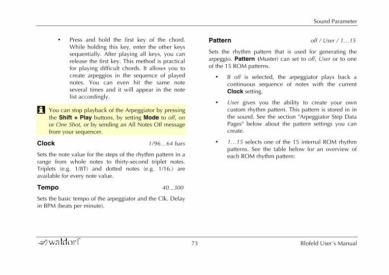
Sound Parameter
73 Blofeld User´s Manual
• Press and hold the first key of the chord. While holding this key, enter the other keys sequentially. After playing all keys, you can release the first key. This method is practical for playing difficult chords. It allows you to create arpeggios in the sequence of played notes. You can even hit the same note several times and it will appear in the note list accordingly.
w You can stop playback of the Arpeggiator by pressing the Shift + Play buttons, by setting Mode to off, on or One Shot, or by sending an All Notes Off message from your sequencer.
Clock 1/96…64 bars Sets the note value for the steps of the rhythm pattern in a range from whole notes to thirty-second triplet notes. Triplets (e.g. 1/8T) and dotted notes (e.g. 1/16.) are available for every note value.
Tempo 40...300 Sets the basic tempo of the arpeggiator and the Clk. Delay in BPM (beats per minute).
Pattern off / User / 1…15 Sets the rhythm pattern that is used for generating the arpeggio. Pattern (Muster) can set to off, User or to one of the 15 ROM patterns.
• If off is selected, the arpeggiator plays back a continuous sequence of notes with the current Clock setting.
• User gives you the ability to create your own custom rhythm pattern. This pattern is stored in in the sound. See the section "Arpeggiator Step Data Pages" below about the pattern settings you can create.
• 1…15 selects one of the 15 internal ROM rhythm patterns. See the table below for an overview of each ROM rhythm pattern:

Sound Parameter
Blofeld User´s Manual 74
w Note that you can edit a ROM pattern to create your own rhythms starting from an existing ROM pattern. As soon as you do so, the ROM pattern is copied to the User pattern and the previous User pattern is overwritten.
Direction Up / Down / Alt Up / Alt Down Sets the direction that is used to play back the arpeggio.
• If Up is selected, the note list is played forward and the octaves are transposed upward. The arpeggio starts in the original octave and goes up to the highest octave. Then the arpeggio is repeated.
• If Down is selected, the note list is played backward and the octaves are transposed downward. The arpeggio starts in the highest octave and goes down to the original octave. Then the arpeggio is repeated.
• If Alt Up is selected, the note list is first played forward and the octaves are transposed upward. After reaching the last note of the note list in the highest octave to play, the note list is played backward and the octaves are transposed downward down to the first note of the note list in the original octave. Then the arpeggio is repeated.
• If Alt Down is selected, the note list is first played backward and the octaves are transposed downward. The arpeggio starts in the highest octave. After reaching the first note of the note list in the original octave, the note list is played forward and the octaves are transposed upward up to the last note of the note list in the highest octave to play. Then the arpeggio is repeated.
! ! ! ! ! ! ! ! ! ! ! !! ! ! ! ! ! ! !! ! ! ! ! ! ! ! ! !! ! ! ! ! ! ! ! ! !! ! ! ! ! ! ! ! ! !! ! ! ! ! ! ! ! ! !! ! ! ! ! ! ! ! !! ! ! ! ! ! ! ! !! ! ! ! ! ! ! ! ! ! ! !! ! ! ! ! ! ! ! ! ! !! ! ! ! ! ! ! ! ! !! ! ! ! ! ! ! ! ! !! ! ! ! ! ! ! ! ! !! ! ! ! ! !! ! ! ! ! ! ! !
!
"
#
$
%
&
'
(
)
!*
!!
!"
!#
!$
!%
+,--./0 ! " # $ % & ' ( ) !* !! !" !# !$ !% !&

Sound Parameter
75 Blofeld User´s Manual
Octave 1...10 Determines the range of the single notes in octaves. When it is set to 1 Oct, the note list will be played back in the same octave as originally entered Greater values mean that the note list is repeated in higher or lower octaves. The octave in which the arpeggio starts is determined by the Direction parameter. If you play notes that span more than one octave, they are still kept in the note list and played back before the note list is transposed. The following table shows some possible arpeggios:
Note input Range Direction Resulting Arpeggio
C1 E1 G1 1 Oct Up C1 E1 G1 | C1 E1 G1
C1 E1 G1 2 Oct Up C1 E1 G1 | C2 E2 G2 | C1 E1 G1 | C2
E1 G1 C1 3 Oct Up E1 G1 C1 | E2 G2 C2 | E3 G3 C3 | E1
C1 G1 E2 3 Oct Up C1 G1 E2 | C2 G2 E3 | C3 G3 E4 | C1
C1 E1 G1 3 Oct Down G3 E3 C3 | G2 E2 C2 | G1 E1 C1 | G3
C1 E1 G1 2 Oct Alt Down G2 E2 C2 | G1 E1 | C1 E1 G1 | C2 E2
Arpeggio results depending on note input
Length 1/96…48 bars / Legato Sets the length of the generated arpeggio notes. However, when Length is set to legato, all arpeggio notes are played without pauses between each step and Arpegiator Length therefore has no effect.
Overlap on / off Due to the various Length parameters, it might happen that two notes having equal pitch overlap, e.g. when you

Sound Parameter
Blofeld User´s Manual 76
play only one single note on a 16 beat rhythm with lengths set to 1/8.
Note that this parameter only affects notes of the same pitches. If you want to control the lengths of notes of different pitches, use the Length or Arrpegiator Length parameters.
• If on is selected, the Note Off message of the previous note is allowed to be sent after a Note On message of the next note with the same pitch. This setting can be nice with arpeggios triggering sounds with slow attack.
• If off is selected, the Note Off message of the previous note is sent right before the next note with the same pitch is started.
Timing Factor 0...127 Determines how much the Arp Timing parameter affects an arpeggio step. If Timing Factor is set to 0, the settings in Arp Timing are completely ignored and the arpeggio is played back without any shuffled timing. Settings from 1 to 127 increase the shuffling of the notes depending on the setting in the Arp Timing parameter. Timing Factor also works on ROM patterns; these are set up with standard swing rhythm.
Velocity Each Note / First Note / Last Note / fix 32 / fix 64 / fix 100 / fix 127 Determines how velocity is interpreted in the arpeggio. Note that each arpeggio step might have an additional positive or negative offset set by the Arp Accent parameter.
• If Each Note is selected, each note of the arpeggio is played back with the velocity that you originally played.
• If First Note is selected, the first note you played sets the velocity for all arpeggio steps.
• If Last Note is selected, the last note you played sets the velocity for all arpeggio steps.
• If one of the fix values is selected, all notes will be played with the selected velocity.
Pat. Length 1...16 Sets the length of the rhythm pattern. This parameter is also valid when Pattern is set to Off or if one of the ROM patterns is selected. Note that you can only edit a particular step in the Step Data pages when its position is within the range of the Pattern Length parameter.

Sound Parameter
77 Blofeld User´s Manual
Pat. Reset off / on When all steps of an arpeggio pattern are played back, the pattern is repeated from the beginning so that the arpeggio is looped. With Pattern Reset, you can decide if the note list is also restarted from the beginning when the rhythm pattern is reset.
• If off is selected, the note list is not restarted, so that there is no synchronization between rhythm and note list. E.g., when you have a pattern where four steps are set and you play three notes, the pattern and the note list are repeated differently. The pattern restarts after the fourth step while the note list restarts after the third step. The arpeggio might look like this:
Pattern Step 1 2 3 4 1 2 3 4
Note C1 E1 G1 C1 E1 G1 C1 E1
Pat. Step 1 2 3 4 1 2 3 4
Note G1 C1 E1 G1 C1 E1 G1 C1
Arpeggio with Pattern Reset set to „on“
• If on is selected, the note list will be restarted as soon as the rhythm pattern is restarted. The same
arpeggio might now look like this (note the two C1s in sequence):
Pattern Step 1 2 3 4 1 2 3 4 Note C1 E1 G1 C1 C1 E1 G1 C1
Pat. Step 1 2 3 4 1 2 3 4
Note C1 E1 G1 C1 C1 E1 G1 C1
Arpeggio with Pattern Reset set to „Off"
Arpeggiator Step Data Pages The following Arpeggiator menu pages all behave similarly. The left display parameter dial sets the Position of the step that should be changed while the right display parameter dial changes the value of the selected step. The Position parameter is similar on each arpeggiator step data page. Use the Selection dial to select between Step, Accent, Glide, Timing and Length.
w You can only select the steps that are in the range set by Pat. Length. E.g., when you have set Pat. Length to 8, you can’t change a value of step 9 or above.
Sound Parameter
Blofeld User´s Manual 78
Step miscellaneous step data This parameter can have a pronounced effect on the resulting arpeggio, so you should read the following paragraphs carefully. Arp Step basically determines which note of the note list is played at a particular step. You can also force the Arpeggiator to play a whole chord or part of a chord or set it up to play a random note from the list.
• If • normal is selected, the Arpeggiator plays the step unaltered. The note list is advanced beforehand, except when you press a new chord.
• If o pause is selected, the Arpeggiator plays nothing at this step position. When Length is set to legato, the previous step that isn’t set to pause is still held to create the legato effect. The note list is not advanced.
• If previous is selected, the Arpeggiator plays the same note as it had to play in the previous step that was set to • normal or ? random. With this setting, you can repeat a particular note of the note list several times. The note list is not advanced.
• If first is selected, the Arpeggiator plays the very first note of the note list. This might be interesting
if you want to only play the "root note" of a chord in a bass sound. The note list is not advanced.
• If last is selected, the Arpeggiator plays the very last note of the note list. The note list is not advanced.
• If first+last is selected, the Arpeggiator plays a chord with two notes, the first and the last one of the note list. This means that you have to play at least two notes to hear the effect. Otherwise, you would hear only one note anyway. The note list is not advanced.
• If ı chord is selected, the Arpeggiator plays a chord with all notes from the note list. This means that you have to play at least two notes to hear the effect. The note list is not advanced.
• If ? random is selected, the Arpeggiator plays a random note from the note list. This doesn’t mean that it creates a note randomly; instead it uses one note of the existing note list. The note list is not advanced.
Accent miscellaneous step data Sets the accent of a particular step. This accent is interpreted as a velocity offset that is added or subtracted

Sound Parameter
79 Blofeld User´s Manual
from the original velocity stored in the note list. However, the generated velocities can never exceed the maximum MIDI velocity 127 or minimum MIDI velocity 1. This means when you have already played notes with a high velocity, Accent might not be able to further offset them positively, so you will only hear differences with negative accent offsets. Conversely, low velocities might not be able to be lowered by Accent. The only exception is silent. See the following description:
• If silent is selected, the current step is actually played, but inaudible. This means that the note list is advanced by one note, but you are not able to hear it. This feature is the opposite to Step set to o pause, which doesn’t generate any note and therefore doesn’t advance the note list.
• If *1 is selected, the velocity of the current step is not altered. The arpeggio steps are played back with their original velocity.
• If Arp Accent is set to any divisor (/4, /3, /2) or multiplicator (*2, *3, *4) the velocity is raised or lowered accordingly. For example a played velocity of 64 generates a final velocity of 32 when set to /2 and 128 when set to *2.
Glide off / on For each step in the arpeggio pattern you can activate the glide effect individually. This gives you the ability to create the classic "Bass Line" melody character. Make sure that you set up a reasonable glide effect in the Oscillator Edit menu.
• If off is selected (empty space), the glide effect is disabled for this step.
• If on is selected, the glide effect is enabled for this step. This means that the previous note glides to the note that has to be played at this particular position in the arpeggio.
w Please note that Glide in the Oscillators Edit Menu must be set to off when you want to set Arp Glide for individual pattern notes. Otherwise, the glide effect will occur on all notes.
Timing random / -3...+3 Moves the playback time of a step forward or backward. Forward means that a step is played later while backward means that it is played earlier. The overall strength of this parameter is set by Timing Factor. If Timing Factor is set to 0, Arp Timing has no effect on the rhythm at all. If Timing Factor is set to maximum, Arp Timing can move
Sound Parameter
Blofeld User´s Manual 80
the step by a maximum of half the clock division. This means that it can move the step by 1/32 forward or backward when clock is set to 1/16.
• random moves the step forward or backward at random. It might also be played without being moved.
• Negative values (-3, -2 oder -1) move the step backward so that it is played earlier.
• If 0 is selected, the step isn’t moved at all.
• Positive values (+1, +2, +3) move the step forward so that it is played later.
Length legato / -3...+3 Changes the length of the note of a particular step. The overall length of the arpeggio depends on the Length setting. If Length is set to legato, Arp Length doesn’t have any effect at all. Also, if Length is set to a very small value, Arp Length might not have an audible effect when you set it to a negative value. You can create very nice staccato and legato effects with this parameter.
• If legato is selected, the notes of this step are held until the next step is played. Empty steps force any step notes set to legato to remain held.
• Negative values (-3, -2 oder -1) shorten the length of the notes of this step.
• If 0 is selected, the step is held for the time set in the Length parameter.
• Positive values (+1, +2, +3) extend the note duration of this step.

Global Parameter
81 Blofeld User´s Manual
Global Parameter Global parameters are settings that affect the Blofeld’s general response. They are valid for all programs but might be overridden by other more specific settings. Global parameters are stored automatically when you modify them, so you are not required to save them manually.
Global Menu All Global parameters are located in the Global Menu. Hold the Shift button and press the Global button to access the Global menu. Use the with the Selection Dial to select the desired menu page. The menu parameters are changed with the corresponding display parameter dials.
Contrast 0...127 Sets the display contrast. If you accidentally set this parameter to 0, you may not be able to read the display any more. If you then switch the Blofeld off and back on later, it might appear that the Blofeld is defective. If this should ever happen, open this manual and proceed as follows:
• Switch the Blofeld on.
• Press and hold the Shift button and after that the Global button to enter the Global menu.
• Use the left display parameter dial to change the Contrast to a desired value.
w You can also send your Blofeld to a qualified Waldorf Service Center. But be sure we will retain your synthesizer for almost 3 months and give it not back until we receive two pounds of chocolate bars from you.
Popup Time 1.1s...15.5s Here you can adjust for how long a time the name and value are shown in the the display when you perform any parameter edits.
w As a newcomer to the Blofeld you should choose a higher setting, around 5-10 sec. After you have had more experience with the Blofeld, you might lower this value to around 1.5 sec.
Auto Edit off / on Auto Edit changes the behaviour when editing the Blofeld.
• When set to off the Blofeld acts as follows: When you press one of the Parameter matrix buttons

Global Parameter
Blofeld User´s Manual 82
shortly the corresponding button is activated but the corresponding Edit menu won´t accessed. If you press the button awhile, the corresponding Edit menu is accessed. off is for advanced users.
• If set to on the Blofeld acts as follows: When you press one of the Parameter matrix buttons shortly the corresponding button is activated and the corresponding Edit menu is shown in the display. This settings is recommended for beginners.
Master Tune 430...450 Controls the Blofeld’s overall pitch in Hertz. The value specified here is the reference pitch for MIDI note A3. The default setting is 440Hz, which is commonly used by most instruments.
m You should only change this setting if you really know what you’re doing. You will have to adjust all your other instruments, too. Don’t forget to set it back again!
Transpose -12...+12 Allows a global pitch transposition for the tone generator. Incoming MIDI notes are shifted by the number of semitones.
MIDI Channel omni, 1...16 Sets the basic send and receive channel for the Blofeld. This setting is valid for all Sound programs. If omni is selected, the Blofeld sends on channel 1 and receives on all channels.
m Please use omni only for test purposes if you wish to check the basic MIDI send and receive functionality. As soon as you know that the Blofeld receives MIDI properly, set MIDI Channel to any other value than omni.
Device ID 0...126 Defines the device identification number for system exclusive data transmission. The number in brackets shows the current ID in hexadecimal number format.
System Exclusive data contains no MIDI channel information so this ID is used to distinguish between several Blofelds, if you have more than one Waldorf Blofeld in your setup.
Transmission will only be executed successfully if the sender and receiver are set to the same ID. ID 127 is a so-called broadcast ID that addresses all connected Blofelds. The Blofeld can receive Sysex data broadcast from other

Global Parameter
83 Blofeld User´s Manual
devices, but cannot send it itself. This function is limited to special computer software.
w Operating System upgrades are stored with a Device ID of 127, so you don’t need to change the Device ID on your Blofeld when you want to upgrade it to a newer OS.
m If you have only one Blofeld, leave Device ID on 0. There is no need at all to change this setting to any other value.
✻ After you have bought your 128th Blofeld, please contact Waldorf Music. You will receive a personal device number that authorizes you to have dinner with our Managing Director. Be sure we invite you for some french fries at our favorite burger company.
Velo Curve linear, square, cubic, exponential, root, fix 32...127 Determines the velocity performance of a connected MIDI keyboard.
Clock Internal / Auto
Determines how the Blofeld reacts on incoming MIDI Clock messages:
• Internal means that the Blofeld doesn’t react on incoming MIDI Clock nor does it send MIDI Clock. The Blofeld only syncs to its own tempo base that is set by Tempo which can be found in the Arpeggiator menu.
• Auto means that the Blofeld automatically syncs to incoming MIDI Clock if it is sent to it by an external device like a sequencer or drum machine. If there is no MIDI Clock present, the Blofeld generates its internal tempo base. This is the recommended setting that works in almost all situations.
Ctrl Send off / Ctl / SysEx / Ctl+SysEx
Determines how Real-Time Sound Parameter Changes are sent by the Blofeld over USB-MIDI.
• If Off is selected, no data is sent.

Global Parameter
Blofeld User´s Manual 84
• If Ctl is selected, only controller messages are sent. Parameters without a dedicated controller are not sent at all.
• If SysEx is selected, all Sound parameters are sent as system exclusive messages. This has the advantage that the parameter change is not channel based but instrument based, which can avoid unwanted parameter changes of layered sounds. The disadvantage is a larger amount of data that is transferred.
• If Ctl+SysEx is selected, all Sound parameters with a dedicated controller assignment are sent as controller messages. All other Sound parameters are sent as system exclusive messages. This is the recommended setting..
Ctrl Receive off / on
Determines if Real-Time Sound Parameter Changes are received over MIDI by the Blofeld.
• If Off is selected, no Sound Parameter Changes are received.
• If On is selected, all Sound Parameter Changes are received, no matter if they were sent as controller or system exclusive messages.
w Set Ctrl Receive to On during normal operation. You should only set it to Off for diagnostic purpose.
Control W...Z 0...120 These parameters are used to define arbitrary MIDI Continuous Controllers as modulation sources for Sounds. You can setup four Controls, W, X, Y and Z, for this purpose. Each value represents a MIDI Continuous Controller number that is used when you assign its parameter as modulation source in the Modifiers or the Modulation Matrix. The highest possible Controller number is 120 because all higher numbers are reserved for non-real-time purposes.

Global Parameter
85 Blofeld User´s Manual
w The most important Sound parameters of the Blofeld can be controlled by MIDI Continuous Controller messages. If you set one of the Ctrl W…Ctrl Z to a Controller that is also used for a Sound parameter, the Blofeld disables this Controller as Sound parameter Controller and uses it exclusively for one of the Ctrl W…Ctrl Z. This is an important issue when you send Sound parameter changes by tweaking parameters on the front panel. The Sound parameter is sent out as Controller but can’t be received as long as you don’t change Ctrl W…Ctrl Z to other MIDI Continuous Controller messages.
Free Button (Blofeld Keyb. only) miscellaneous This button can be defined with an assignable function.
• off - nothing happens when you press the Free button.
• Sustain - The button acts like a sustain pedal. But please use your fingers!
• Sust. toggle - Also sustain, but it acts like an on/off switch.
• Control W, X, Y, Z - the corresponding controller is sent to internal sound engine and MIDI out.
• C. W, X, Y, Z toggle - Emits the assigned controller but acts like an on/off switch.
• mute - mutes Blofeld while pressed.
w We omitted a Mute toggle function to minimize the amount of muted Blofelds sent in for repair.
Pedal (Blofeld Keyboard only) normal / inverse Determines the way, a connected switch pedal is evaluated by the Blofeld Keyboard.
• normal is for a switch pedal that is closed when pressed and open when not pressed.
• inverse is for a switch pedal that is open when pressed and closed when not pressed.

Global Parameter
Blofeld User´s Manual 86
Utility Menu Aside from the different Midi Dump Options, the Utility Menu contains further helpful functions.
You can access the Utility Menu by pressing Shift + Utility. In the display a page for selecting the desired function will appear.
Use the Selection dial to select the desired function. Press Shift+ Utility again to activate the selected utility function.
Store Sound Function
The Store Sound function is described in detail on page 22 of this manual.
Help Functions
The Compare Sound and Recall Sound functions are described in detail on page 21 and 22 of this manual.
Use the Init function to initialize a sound to ist basic parameter settings. This is useful if you want to start programming a sound from the scratch.
w When you initialize a program, all action takes place inside an edit buffer. Therefore no data will be lost until you store the program.
Randomize Sound initializes all parameters of a Sound Program with random values.
w When you randomize a program, all action takes place inside an edit buffer. Therefore no data will be lost until you store the program.
✻ Use Randomize as much as possible. This is how most of the Blofeld´s presets are programmed ;-)
MIDI Dump Functions
The dump functions let you send and receive the contents of the Blofeld’s memory via MIDI (receiving only) or USB.
When you activate the send functions, the Blofeld sends the contents of its memory to the USB port to a connected computer. Using a sequencer software or a special sound editor program, you can record and archive this data.
w The available dump options depend on the used mode. In Multimode additional dump options are available.
Global Parameter
87 Blofeld User´s Manual
☞ To activate the dump function in Play mode:
1. Use the Selection dial to select the desired dump function:
• If Dump Sound is selected, the current Sound program will be sent.
• If Dump Sound Bank is selected, the current Sound Bank will be sent.
• If Dump All Sounds is selected, all Sound programs of the Blofeld are sent.
• If Dump All all Sound programs and the Global parameters are sent.
2. Press Shift + Utility to activate the dump.
☞ To activate the dump function in Multimode:
1. Use the Selection dial to select the desired dump function:
• If Dump Multi is selected, the current Multi program will be sent. All corresponding sound programs will not sended within this dump.
• If Dump Arrangement is selected, the current Multi program including all sound programs will be sent.
• If Dump All Multis is selected, all Multi programs of the Blofeld are sent.
2. Press Shift + Utility to activate the dump
w Depending on the selected type, the dump may take some time. The Blofeld cannot be played during this time.
Receiving System Exclusive Data You are not required to activate a special receive mode of the Blofeld in order to receive system exclusive data through MIDI or USB. However, there are a few things you should check before you transmit system exclusive data to the Blofeld:
• Make sure none of the Blofeld’s programs is in Edit mode. The edit buffers might be cleared or overridden depending on the type of dump that is sent to the Blofeld.
• Check out the parameter Device ID. Data transmission will only be executed successfully if if the sender and receiver settings match.

Global Parameter
Blofeld User´s Manual 88
As soon as the dump from the sending device is activated, the Blofeld will receive data and store these in its memory.
If a single Sound dump is received, it is temporarily stored in its respective edit buffer. If you want to keep such edits, you have to store them. Otherwise they are when you switch the Blofeld off.

Sound Synthesis Basics
89 Blofeld User´s Manual
Sound Synthesis Basics Oscillators Introduction The oscillator is the first building block of a synthesizer. It delivers the signal that is transformed by all other components of the synthesizer. In the early days of electronic synthesis, Robert A. Moog found out that most real acoustic instrument waveforms could be reproduced by using abstracted electronic versions of these waveforms. He wasn’t the first who came to that conclusion, but he was the first in recreating them electronically and building them into a machine that could be used commercially. What he implemented into his synthesizer were the still well-known waveforms sawtooth, square and triangle. For sure, this is only a minimal selection of the endless variety of waveforms, but the Waldorf Blofeld gives you exactly these waveforms at hand, plus other classic waveforms like pulse (which is the father of the square waveform) and the sine wave (also part of every other waveform).
Now, you probably know how these waveforms look and sound, but the following chapter gives you a small introduction into the deeper structure of these waveforms. Let’s start with the most basic one.
The Sine Wave The Sine Wave is the purest tone that can be generated. It consists only of one harmonic, the fundamental, and has no overtones. The following picture shows the sine wave and its frequency representation:
The Sine Wave
There is no acoustic music instrument that generates a pure sine wave; the only instrument that comes close to it is the pitch fork. Therefore, the sine wave sounds a little artificial to the ear. However, the sine wave can be an interesting oscillator waveform to emphasize a certain harmonic while other oscillators are playing more complex waveforms, or as FM source for frequency modulation.
The sine wave is the most basic building block of each waveform. Any waveform can be broken down to several or many sine waves that are arranged with different frequencies and magnitudes. These sine waves are called
! " # !$ !%&'()*(+,-
./0+12*3(
415(
657812*3(
9/'5:+1,;

Sound Synthesis Basics
Blofeld User´s Manual 90
partials. In most waveforms, the partial with the lowest frequency is dominant, meaning that this partial is used by the ear to determine the pitch of the tone. This partial is called fundamental. All other partials are called overtones. So, the second partial is the first overtone.
Cyclic waveforms such as the waveforms in the Blofeld only feature sine waves in integer frequency ratios to the fundamental like double frequency, triple frequency and so on. Those partials are called harmonics because their frequency is a harmonic multiple of the fundamental.
Confusing? Let’s generalize it to cyclic waveforms: a cyclic waveform like sawtooth, square etc. only consists of harmonic partials. The harmonic with the lowest frequency is dominant and therefore called fundamental. All other harmonics are called overtones.
The Sawtooth Wave The Sawtooth Wave is the most popular synthesizer waveform. It consists of all harmonics in which the magnitude of each harmonic descends by the factor of its position. This means that the first harmonic (the fundamental) has full magnitude, the second harmonic has half magnitude, the third harmonic has a third magnitude and so on. The following picture shows how the individual harmonics build up the sawtooth wave:
Additive components of the Sawtooth wave
The sawtooth wave was thought as an abstraction of the timbre of string and brass instruments. You can easily understand that when you think of a violin. Imagine a
! " # !$ !%&'()*(+,-
./0+12*3(
415(
657812*3(
9
:
!;2<=/'5>+1,./0+12*3(<!
$+3<=/'5>+1,./0+12*3(<!?$
@'3<=/'5>+1,./0+12*3(<!?@
"2A<=/'5>+1,./0+12*3(<!?"
=/'5>+1,;
9
9
9BB

Sound Synthesis Basics
91 Blofeld User´s Manual
bow pulling the string slightly into one direction. At one point, the string abruptly comes off the bow and swings back to its original position. The bow is still moved and so it catches the string again and the procedure is repeated. The result is a waveform that looks like a sawtooth. The same is true for a brass instrument. The string in this case are the lips while the bow is the air. The lips are moved by the air to a certain extent and abruptly move back to their original position.
The Square Wave The Square Wave is a special waveform generated by a pulse waveform with 50% pulse width. This means that the positive part of the waveform has equal length to the negative part. The pulse waveform can have other pulse widths as you will read later. For now, we´ll talk about the square wave as a unique waveform. The square wave consists of all odd harmonics in which the magnitude of each harmonic descends by the factor of its position. This means that the first harmonic has full magnitude, the third harmonic has a third magnitude, the fifth harmonic has a fifth magnitude and so on. The following picture shows how the individual harmonics build up the sawtooth wave:
Additive components of the square wave with 50% pulse width
The square wave was thought as an abstraction of wind instruments like a panflute or a recorder. They consist of a
! " # $ %&'()*(+,-
./0+12*3(
415(
657812*3(
9
:
!;2<=/'5>+1,./0+12*3(<!
#2?<=/'5>+1,./0+12*3(<!@#
$2?<=/'5>+1,./0+12*3(<!@$
=/'5>+1,;
9
9
9AA
!! !" !#
"'3<=/'5>+1,./0+12*3(<!@"
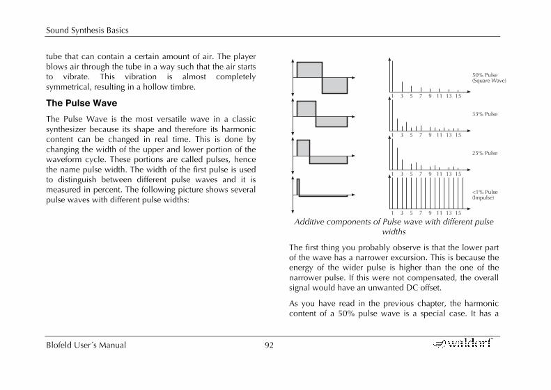
Sound Synthesis Basics
Blofeld User´s Manual 92
tube that can contain a certain amount of air. The player blows air through the tube in a way such that the air starts to vibrate. This vibration is almost completely symmetrical, resulting in a hollow timbre.
The Pulse Wave The Pulse Wave is the most versatile wave in a classic synthesizer because its shape and therefore its harmonic content can be changed in real time. This is done by changing the width of the upper and lower portion of the waveform cycle. These portions are called pulses, hence the name pulse width. The width of the first pulse is used to distinguish between different pulse waves and it is measured in percent. The following picture shows several pulse waves with different pulse widths:
Additive components of Pulse wave with different pulse widths
The first thing you probably observe is that the lower part of the wave has a narrower excursion. This is because the energy of the wider pulse is higher than the one of the narrower pulse. If this were not compensated, the overall signal would have an unwanted DC offset.
As you have read in the previous chapter, the harmonic content of a 50% pulse wave is a special case. It has a
! " # $ % !! !" !#
! " # $ % !! !" !#
! " # $ % !! !" !#
! " # $ % !! !" !#
#&'()*+,-./0*12-(314-5
6#'()*+,-
7!'()*+,-.89:*+,-5
""'()*+,-

Sound Synthesis Basics
93 Blofeld User´s Manual
very symmetrical harmonic content, while all other pulse widths create peaks or troughs at certain frequencies. Another special case is a pulse wave with a very narrow pulse width, in the above picture labelled as <1%. An infinitely thin pulse creates a spectrum that has all harmonics with equal magnitudes. In a digital synthesizer, “infinitely” necessarily means one sample.
The pulse wave is an artificial wave, which means that it doesn’t occur in nature. It was built into synthesizers because it could create a lot of different timbres with a minimum of technical effort. However, certain pulse widths sound very close to the timbres of acoustic (or semi-acoustic) instruments, i.e. a guitar or bass guitar, an e-piano or even a flute.
The most powerful feature of the pulse wave is the ability to change its width while sounding. This is called pulse width modulation. When the pulse width is changed, the waveform starts to sound thicker. This happens because the effect is very similar to what you hear when you have two oscillators running with slightly different frequencies. They interfere and create irregular troughs in the resulting waveforms.
The Triangle Wave The Triangle Wave is very similar to the square wave. It is composed of the same harmonics as the square wave, but with different magnitude ratios. The magnitude of each harmonic is divided by the power of its number. This means that the third harmonic’s magnitude is a ninth, the fifth harmonic is a twenty-fifth and so on. The following illustration shows the harmonic content:

Sound Synthesis Basics
Blofeld User´s Manual 94
Additive components of the Triangle wave
The reason why the triangle wave is so popular in classic synthesizers: It could act as a suboscillator wave, to emphasize certain frequencies or to frequency modulate other oscillators.
The triangle wave sounds like a woodwind instrument, i.e. a clarinet. It can also be used for mallet instruments like vibraphone, xylophone etc.
Wavetable Synthesis in the Blofeld The sound generation of the wavetables in the Blofeld is based on wavetable synthesis. Although wavetable synthesis is not a form of "sample playback", you should avoid this term because functionality, operation and results are totally different. Each of the wavetables contain single 64 waves.
m Please keep the terms "wavetable" and "wave" in mind. Don´t confuse the two.
The following overview explains how the Wavetable Synthesis works: A wavetable into the Blofeld is a table consisting of 64 waveforms. Each waveform is classified by its own special sound character. The main difference of wavetable synthesis in comparison with other sound generation principles is the facility not only to play one waveform per oscillator, but also to walk through the wavetable via different modulations. Therefore you can create wavetable sweeps. The results can be dramatic - much more so than those any sample playback based system could ever produce. This is a unique feature of wavetable synthesis.
! " # $ %&'()*(+,-
./0+12*3(
415(
657812*3(
9
:
!;2<=/'5>+1,./0+12*3(<!
#2?<=/'5>+1,./0+12*3(<!@A#
$2?<=/'5>+1,./0+12*3(<!@B%
=/'5>+1,;
9
9
9CC
!! !" !#
"'3<=/'5>+1,./0+12*3(<!@%

Sound Synthesis Basics
95 Blofeld User´s Manual
This principle offers powerful capabilities. To give some examples:
• Each note on a keyboard can access a different wave of a wavetable.
• Different waves can be played depending on key velocity.
• A LFO can modulate the position within the wave-table. You can create subtle to drastic sound changes.
• User-selected controllers e.g. the mod wheel, can change the position within the wavetable. When you turn the wheel while playing a chord, each note´s wave will be modified intantly.
• Wavetables are perfect as FM sources when you want to create very strange sounds.
You should keep the following sentence in mind:
A wavetable is a list with 64 waves, among which you can move at will.
w If you like the sound and possibilities of wavetable synthesis, you should try out the virtual instrument Waldorf PPG Wave 2.V which is part of the Waldorf Edition plug-in bundle.
List of Wavetables used in the Blofeld
No. Wavetable No. Wavetable
1 Alt 1 35 SawSync1
2 Alt 2 36 SawSync2
3 Resonant 37 SawSync3
4 Resonant2 38 PulSync1 5 MalletSyn 39 PulSync2
6 Sqr-Sweep 40 PulSync3
7 Bellish 41 SinSync1
8 Pul-Sweep 42 SinSync2
9 Saw-Sweep 43 SinSync3
10 MellowSaw 44 PWM Pulse 11 Feedback 45 PWM Saw
12 Add Harm 46 Fuzz Wave
13 Reso 3 HP 47 Distorted
14 Wind Syn 48 HeavyFuzz
15 HighHarm 49 Fuzz Sync
16 Clipper 50 K+Strong1 17 OrganSyn 51 K+Strong2
18 SquareSaw 52 K+Strong3
19 Formant1 53 1-2-3-4-5

Sound Synthesis Basics
Blofeld User´s Manual 96
20 Polated 54 19/twenty
21 Transient 55 Wavetrip1
22 ElectricP 56 Wavetrip2
23 Robotic 57 Wavetrip3
24 StrongHrm 58 Wavetrip4 25 PercOrgan 59 MaleVoice
26 ClipSweep 60 Low Piano
27 ResoHarms 61 ResoSweep
28 2 Echoes 62 Xmas Bell
29 Formant2 63 FM Piano 30 FmntVocal 64 Fat Organ
31 MicroSync 65 Vibes
32 MicroPWM 66 Chorus 2
33 Glassy 67 True PWM
34 SquareHP 68 UpperWaves
Filter Introduction Once the audio signal leaves the mixer, it is sent to the filters. The Blofeld has two independent filter units, each with its own individual settings. The signal flow in the filters can be controlled via the Routing function. The filters are components that have significant influence on the Blofeld’s sound characteristics.
For a detailed description of the different filter types that are available in the Blofeld, see the section “Filter Types” on page 78. For now, we’ll explain the basic function of a filter discussing the type used most commonly in synthesizers: the low pass filter.
The low pass filter type dampens frequencies that lie above a specified cutoff frequency. Frequencies below this threshold are hardly affected. The frequency below the cutoff point is called the pass band range, the frequencies above are called the stop band range. The Blofeld’s filter dampens frequencies in the stop band with a certain slope. The slope can be 12dB or 24dB per octave. This means that the level of a frequency that lies an octave above the cutoff point will be 12dB or 24dB less than those frequencies of the signal that fall into the pass band. The following picture shows the basic principle of a low pass filter:

Sound Synthesis Basics
97 Blofeld User´s Manual
To give you an idea of the extent of damping, consider this example of a low pass filter: A reduction of 24dB reduces the original level one octave above the cutoff point by approx. 94%. The damping factor two octaves above the cutoff point reduces the original level by more than 99%, which in most cases means this portion of the signal is no longer audible.
The Blofeld’s filter also features a resonance parameter. Resonance in the context of a low, band or high pass filter means that a narrow frequency band around the cutoff
point is emphasized. The following picture shows the effect of the resonance parameter on the filter’s frequency curve:
If the resonance is raised to a great extent, then the filter will begin self-oscillation, i.e. the filter generates an audible sine wave even when it does not receive an incoming signal.
!"#$%#&'(
)#*#+
,%-.//
!"#$%#&'(
)#*#+
,%-.//
0#1.&2&'#

Sound Synthesis Basics
Blofeld User´s Manual 98
The Comb Filter Types The Comb filter types differ from the other filter types greatly, because they don’t actually damp any part of the signal, but instead add a delayed version of the input signal to the output. What exactly is a Comb filter?
A Comb filter is basically a very short delay that can be controlled in length and feedback. The delay time is so short that you can’t hear its individual taps but a colorization of the original signal created by peaks or holes in the frequency spectrum. The frequency of the colorization is set by the delay length, which is controlled in the Blofeld through Cutoff, while the amount of colorization is set by the Comb filter feedback, which is controlled in the Blofeld through Resonance.
Comb+ Filter Type
!"#$%#&'(
)#*#+
,%-.//01#-#"23(&%25#"0./0-##-6
7#4.&8&'#

Sound Synthesis Basics
99 Blofeld User´s Manual
Comb – Filter Type
So, as with all other filter types, the Comb filter is controlled with two parameters:
• Cutoff controls the delay length.
• Resonance controls the feedback depth.
Now, what sound can a comb filter produce? Here are some examples:
The Comb filter as a Chorus This is the most basic way to use the Comb filter. A Chorus in fact is made of one or several Comb filters, so this is an easy task to set up manually.
☞ To set up the Comb filter to produce a Chorus:
1. Select the Comb+ filter type for the desired filter.
2. Set Cutoff to a medium value.
3. Set Resonance, Drive, Filter Keytrack and any other modulation to 0.
4. Select an LFO as Mod Source.
5. Set Mod to a medium positive or negative amount.
6. Adjust the LFO to generate a slow triangle oscillation.
7. Fine tune Cutoff, Mod and LFO Speed until you get the desired Chorus effect.
✻ You can also use both filters to create a Chorus and pan them to different stereo positions.
!"#$%#&'(
)#*#+
,%-.//01#-#"23(&%25#"0./0-##-6
7#4.&8&'#

Sound Synthesis Basics
Blofeld User´s Manual 100
✻ You can also pan the original, i.e. low pass filtered signal, to one stereo side and route 50% into Filter 2, producing a Chorus effect that is panned to the other stereo side.
You might ask why you should use a Comb filter type to produce Chorus instead of using the FX section of the Blofeld. Here are some reasons:
• The FX sections remain free for other purposes. Also, in Multi Mode, the Comb filter works no matter on which Instrument you use it.
• The Comb filter works per voice rather than per Instrument. This means that each voice has its own Chorus and therefore could generate a different Chorus effect. You can easily hear this when you change LFO Keytrack or Filter Keytrack. Now, each voice sounds with a different Chorus speed or frequency.
• You have full control over MIDI of all parameters that make up the Chorus effect, by using Control messages.
The Comb filter as a Flanger A Flanger is almost the same as a Chorus. The only difference is that it has feedback circuitry to change the depth of the Flanger effect.
☞ To set up the Comb filter to produce a Flanger:
1. Adjust the filter as described in the Chorus paragraph above.
2. Turn up Resonance to create the typical Flanger sound.
3. Gradually lower LFO Speed to create slow Flanger sweeps.
4. Select either Comb+ or Comb- to change the character of the Flanger.
✻ Set up Mod Source to Modwheel to change the Flanger effect manually.
✻ Use the Filter Envelope with positive or negative amount to create a “one time sweep” that is triggered at Note On.
✻ Use Filter Keytrack with an amount of 100% to create really different flangings depending on the Note you play.

Sound Synthesis Basics
101 Blofeld User´s Manual
The Comb filter used to simulate a string or a tube The Comb filter is one of the most basic building blocks of “Physical Modeling”, which is the term for an algorithmic description of an acoustic instrument. The Blofeld is definitely not meant to replace a good physical modeling synthesizer, so you shouldn’t expect to get a perfect emulation of an acoustic instrument like a trumpet or a violin out of the Blofeld. However, the Comb filter enables you to create abstractions of those sounds that can be played expressively.
To do so, you have to understand that the Comb filter is the part that actually sets the pitch of the resulting sound; the oscillators or the noise generator are only used to trigger the Comb filter somehow. When you play with the Comb filter, you can hear that it emphasizes or attenuates certain frequencies depending on the setting of Cutoff and Resonance.
When you set Resonance to a very high value, you will notice that the Comb filter oscillates heavily, and that’s the key to using it as a tone generator. When you set Filter Keytrack to +100%, you can play the Comb filter musically.
Now you need to know how to set up Cutoff. Filter Cutoff is scaled in semitone steps, and you only have to find the Cutoff value where the filter oscillates with standard pitch. The following table gives you these settings:
Oscillator Comb+ Comb- 64’ 11 23
32’ 23 35
16’ 35 47
8’ 47 59
4’ 59 71 2’ 71 83
Comb Filter Cutoff settings
If you need other tunings, just keep in mind that Cutoff is changed in semitones, so if you increment Cutoff by 12, the filter oscillates one octave higher, and so forth.
☞ To set up the Comb filter to produce a tone:
1. Select either Comb+ to produce a string-like tone or Comb- to produce a tube-like tone.
2. Turn up Resonance to around 114 to 127.

Sound Synthesis Basics
Blofeld User´s Manual 102
3. Turn up Filter Keytrack to +100% to have Filter Cutoff change with equal-tempered scaling.
4. Set Cutoff to 23, 35, 47 or 59 to have it oscillating in the same pitch as the oscillator´s usually tuning. Please note that Comb+ oscillates one octave higher than Comb-.
5. Feed the Comb filter with a signal of any kind. The incoming signal’s pitch isn’t important for the resulting tuning, but both pitch and timbre of the input signal affect the timbre of the Comb filter output sound greatly.
✻ Try to experiment with all kinds of input signals, i.e. different oscillator settings, noise, combinations of both and the like.
✻ Also try to set up envelopes to control the levels of the input signal, i.e., use a short percussive signal that only triggers the comb filter briefly. The filter then oscillates to produce the resulting tone.

Sound Synthesis Basics
103 Blofeld User´s Manual
Envelope Types in the Blofeld
ADSR Envelope Most traditional synthesizers feature ADSR envelopes. These envelopes are made up of four parameters that determine their response: Attack, Decay, Sustain and Release. The other parameters of the Envelope section have no function, so they can not be edited. The following picture illustrates the structure of an ADSR envelope:
ADSR Envelope
The envelope is started by pressing a key. It ascends to its maximum value at the rate determined by the Attack parameter. It then descends at the rate determined by the Decay value until it reaches the predetermined Sustain value. It remains at this value until the key is released. The envelope then descends to zero at the rate determined by the Release parameter.
ADS1DS2R Envelope A difficult name for an envelope that is quite easy to understand. Besides the parameters an ADSR envelope features, it offers an adjustable attack level and a second
!""#$% &'$#(
)*+"#,-
.'/'#+'
0'(123'++'4 0'(13'/'#+'4
5,6'
7'8'/
9::;

Sound Synthesis Basics
Blofeld User´s Manual 104
Decay and Sustain pair. With these additional parameters, you can create much more complex envelopes.
ADS1DS2R Envelope
One Shot Envelope The One Shot envelope type is designed for percussive sounds that don’t need a stage maintained as long as a note is played. In other words: the envelope goes through all its stages, no matter how long a key is pressed. This includes even the Attack phase. It uses the parameter set of the ADSR envelope type in which the Sustain parameter is used to set a level breakpoint. This allows creation of One Shot envelopes with a very percussive attack or with a “Gate” effect. Some parameters of the Envelope section have no function so they can not be edited.
One Shot Envelope
Loop S1S2 Envelope The Loop S1S2 envelope type loops the envelope between Sustain 1 and Sustain 2 as long as a note is held, after has been through the Attack phase once. This means that when Sustain 2 is reached, Decay 1 is used to reach Sustain 1 again, then Decay 2 is used to reach Sustain 2, and so on. As soon as the note is released, the envelope proceeds with the Release phase. It uses the parameter set of the ADS1DS2R envelope.
!""#$% &'$#(
)*+"#,-
.'/'#+'
0'(123'++'4 0'(13'/'#+'4
5,6'
7'8'/
9::;
!""#$%17'8'/)*+"#,-1<
&'$#(1< !""#$% &'$#(
)*+"#,-
.'/'#+'
0'(123'++'415316,"1+653"/(
7,8'
9':'/
;<<=

Sound Synthesis Basics
105 Blofeld User´s Manual
Loop S1S2 Envelope
Loop All Envelope The Loop All envelope type is similar to the Loop S1S2 envelope type but it loops through all envelope stages as long as a note is held. This means that it goes through all envelope stages first, and if it ended with the Release phase, the envelope restarts from zero and goes through all its phases again. As soon as the note is released, the looping stops and the envelope goes into its Release phase.
Loop All Envelope !""#$% &'$#(
)*+"#,-
.'/'#+'
0'(123'++'4 0'(13'/'#+'4
5,6'
7'8'/
9::;
!""#$%17'8'/ )*+"#,-1<
&'$#(1<
7==2
!""#$% &'$#(
)*+"#,-
.'/'#+'
0'(123'++'4 0'(13'/'#+'4
5,6'
7'8'/
9::;
!""#$%17'8'/ )*+"#,-1<
&'$#(1<
7==2

Appendix
Blofeld User´s Manual 106
Appendix FM Sources FM Source: Description:
off No modulation
Osc1 Oscillator 1 Signal
Osc2 Oscillator 2 Signal
Osc3 Oscillator 3 Signal Noise Noise Generator Signal
LFO1 LFO 1 Signal
LFO2 LFO 2 Signal
LFO3 LFO 3 Signal
FilterEnv Filter Envelope Signal
AmpEnv Amplifier Envelope Signal Env3 Envelope 3 Signal
Env4 Envelope 4 Signal
Modulation Sources Modulation Source: Description
off No modulation
LFO1 LFO 1 Signal
LFO1*MW LFO 1 Signal shaped by Modwheel
LFO2 LFO 2 Signal
LFO2*Prs. LFO 2 Signal shaped by Aftertouch
LFO3 LFO 3 Signal
FilterEnv Filter Envelope Signal AmpEnv Amplifier Envelope Signal
Env3 Envelope 3 Signal
Env4 Envelope 4 Signal
Keytrack MIDI note number
Velocity MIDI Velocity Rel. Velo MIDI note release velocity
Pressure MIDI channel pressure
Poly Prs. MIDI polyphonic pressure
Pitchbend MIDI pitchbend signal
Modwheel MIDI modulation wheel (contr. #1)
Sust. Ctr MIDI sustain pedal (controller #64) Foot Ctr MIDI foot control (controller #4)
BreathCtr MIDI breath control (controller #2)
Control W, X, Y, Z assignable MIDI controller W to Z
Unisono V All Unisono voices
Modifier #1...#4 Result of Modifier #1...#4
minimum constant for minimum modulation

Appendix
107 Blofeld User´s Manual
(equals 0)
MAXIMUM constant for maximum modulation (equals +1)
Modulation Destinations Modulation Destination:
Description:
Pitch Global pitch of all three Oscillators at once
O1 Pitch, O2 Pitch, O3 Pitch
Pitch of Oscillator 1…3
O1 PW, O2 PW, O3 PW
Pulse width of Oscillator 1…3
O1 FM, O2 FM, O3 FM
FM Amount modulation of Oscillator 1…3
O1 Level, O2 Level, O3 Level
Level of Oscillator 1…3
O1 Bal., O2 Bal., O3Bal.
Filter 1/2 Balance of Oscillator 1…3
Ring Level Mixer ring modulation level Ring Bal. Filter 1/2 Balance of Oscillator 1
Noise Level Mixer level of Noise
Noise Bal. Filter 1/2 Balance of Noise
F1 Cutoff, F2 Cutoff Cutoff of Filter 1…2
F1 Reson., F2 Reson. Resonance of Filter 1…2
F1 FM, F2 FM FM Amount modulation of Filter 1…2
F1 Drive, F2 Drive Drive of Filter 1…2
F1 Pan, F2 Pan Pan of Filter 1…2
Volume Amplifier output volume
LFO1-, LFO2-, LFO3-Speed
Speed of LFO 1…3
FE Attack Attack rate of Filter Envelope
FE Decay Decay (and Decay 2) rate of Filter Envelope
FE Sust. Sustain (and Sustain 2) level of Filter Envelope
FE Rel. Release rate of Filter Envelope
AE Attack Attack rate of Amp Envelope
AE Decay Decay (and Decay 2) rate of Amp Envelope
AE Sust. Sustain (and Sustain 2) level of Amp Envelope
AE Rel. Release rate of Amp Envelope
E3 Attack Attack rate of Envelope 3
E3 Decay Decay (and Decay 2) rate of

Appendix
Blofeld User´s Manual 108
Envelope 3
E3 Sust. Sustain (and Sustain 2) level of Envelope 3
E3 Rel. Release rate of Envelope 3
E4 Attack Attack rate of Envelope 4
E4 Decay Decay (and Decay 2) rate of Envelope 4
E4 Sust. Sustain (and Sustain 2) level of Envelope 4
E4 Rel. Release rate of Envelope 4 M1 Amount Modulation amount of M1
M2 Amount Modulation amount of M2
M3 Amount Modulation amount of M1
M4 Amount Modulation amount of M2

Appendix
109 Blofeld User´s Manual
Updating the System Software The Blofeld has a service-friendly feature that makes it possible to update the system software without changing any parts.
All software updates come in the form of a standard MIDI file that can be read by every sequencer. The fastest way to get this file is by downloading it from our web site at:
http://www.waldorfmusic.com
Please make sure to download the following files:
• blofeld_vxx.mid (if it is newer than the one installed in your Blofeld)
• changelog.txt (always download this one, because it explains the latest changes)
w Possibly there will be a .zip file containing the new OS, new sounds and a manual addendum.
If you don’t have Internet access, please ask your local dealer for a disk copy.
☞ To update the Blofeld’s system software:
• Load the respective Standard MIDI File into your sequencer. Follow the instructions from your sequencer’s manual.
• The MIDI file consists of one single track with several sysex messages in it. Make sure that this track is assigned to the Blofeld so that it can receive the data.
• Make sure that any Cycle or Loop mode is switched off. Also make sure that any Metronome clicks and MIDI Clock are switched off.
• Start the sequencer playing the file, and send the track data to the Blofeld.
• The Blofeld will display a message that informs you that the update is in progress.
• After the file is received correctly, the Blofeld burns the update into its FLASH memory.
• Wait until the operation is completed. If updating was successful, the Blofeld will perform a system reset and start up.
Appendix
Blofeld User´s Manual 110
w You can dump an operating system update via MIDI input as also via USB 2 port. We recommend the use of the USB port for updating your Blofeld.
m Do not under any circumstances turn off the Blofeld while this step is in progress. A complete loss of data may occur and it will be impossible for you to make your machine work again!

Appendix
111 Blofeld User´s Manual
Tips & Tricks • Noise as FM Source for an oscillator gives a
colored noise output whose character can be changed with FM Amount, the oscillator waveform and the pitch of the oscillator.
• Use Envelope 3 or 4 to blend in one of the oscillators. E.g, if you need a small blip in the attack phase, just use a free oscillator and a short percussive envelope to create this effect. You can do that in the Modulation Matrix by setting the source to Env3 or Env4, the destination to Osc1, Osc2 or Osc3 level and setting up a positive amount. If this blip should be noisy, use FM with Noise as source for this oscillator to control the strength of the noise.
• For a classic “Filter Trigger” sound, you don’t need to actually use a filter. You can also use a sine oscillator that is pitch modulated by an envelope. This frees up the two filters and you can use them to perform other tasks, e.g. filtering noise for a snare drum sound or the like.
• Use the LFOs as FM Sources. With this technique, you get up to six oscillators frequency-modulating
each other to create extremely complex timbres. Just keep in mind that the LFOs have a maximum speed of around 2500 Hz and that they can produce aliasing side effects.
• Use the wavetables as FM sources. If a LFO modulates the wavetable at the same time, you will create really amazing sounds.
• For extremely wide sounds, you can do the following: Create a sound that uses only Filter 1 with the desired settings. Now set Routing to serial so that both filters are routed to the panning stages with equal volume. Set Filter 2 to a comb filter type with middle or low cutoff and no resonance. Now set the Pan parameters of the filters to opposite directions and you should get a very fat sound. You can create further movement by applying an LFO to the comb filter cutoff.

Appendix
Blofeld User´s Manual 112
Technical Data
Power Supply Nominal voltage: DC 12V
Supply Voltage 100 – 240 V
Maximum current consumption: 0.3 A
Maximum power consumption: 5 W
Dimensions and Weight Blofeld Desktop Width: 304 mm
Depht: 132 mm
Height (including knobs): 54 mm
Total weight: 1,3 kg
Dimensions and Weight Blofeld Keyboard Width: 740 mm
Depht: 275 mm
Height (including knobs): 100 mm
Total weight: 8,0 kg

Appendix
113 Blofeld User´s Manual
Controller Numbers Controllers marked with * don’t change the Sound program but can perform temporary modulations or other tasks.
Ctrl #
Controller Range Controller name or Sound Parameter
Value Range
0 - not used - Bank Select MSB - not used
1 0…127 Modulation Wheel*
0…127
2 0…127 Breath Control* 0…127
3 - not used - undefined - not used -
4 0…127 Foot Control* 0…127
5 0…127 Glide Rate 0…127
6 - not used -- Data Entry - not used - 7 0…127 Channel
Volume* 0…127
8 - not used -- Balance - not used - 9 - not used - undefined - not used -
10 0…127 Pan* L64…R63
11 - not used - Expression - not used -
12 0…9 Arp Range 1…10 octaves
13 0…15 Arp Length 1…16 steps
14 0…3 Arp Active off, on, one shot, hold
15 0…5 LFO 1 Shape sine, triangle, square,

Appendix
Blofeld User´s Manual 114
sawtooth, random, S&H
16 0…127 LFO 1 Speed 0…127 or 256 bars…1/96
17 0…1 LFO 1 Sync off, on
18 0…127 LFO 1 Delay 0…127 19 0…5 LFO 2 Shape sine, triangle,
square, sawtooth, random, S&H
20 0…127 LFO 2 Speed 0…127 or 256 bars…1/96
21 0…1 LFO 2 Sync off, on
22 0…127 LFO 2 Delay 0…127
23 0…5 LFO 3 Shape sine, triangle, square, sawtooth, random, S&H
24 0…127 LFO 3 Speed 0…127 or 256 bars…1/96
25 0…1 LFO 3 Sync off, on
26 0…127 LFO 3 Delay 0…127
27 16, 28, 40…112 Osc 1 Octave 128’…1/2’ 28 52…76 Osc 1 Semitone -12…+12
29 0…127 Osc 1 Detune -64…+63
30 0…127 Osc 1 FM 0…127
31 0…5 Osc 1 Shape pulse, saw, triangle, sine, alt 1, alt 2
32 0…n Bank Select LSB* Bank A... 33 0…127 Osc 1 PW 0…127
34 0…127 Osc 1 PWM -64…+63
35 16, 28, 40…112 Osc 2 Octave 128’…1/2’
36 52…76 Osc 2 Semitone -12…+12
37 0…127 Osc 2 Detune -64…+63
38 0…127 Osc 2 FM 0…127 39 0…5 Osc 2 Shape pulse, saw,
triangle, sine, alt 1, alt 2
40 0…127 Osc 2 PW 0…127
41 0…127 Osc 2 PWM -64…+63
42 16, 28, 40…112 Osc 3 Octave 128’…1/2’
43 52…76 Osc 3 Semitone -12…+12 44 0…127 Osc 3 Detune -64…+63
45 0…127 Osc 3 FM 0…127
46 0…5 Osc 3 Shape pulse, saw, triangle, sine,

Appendix
115 Blofeld User´s Manual
alt 1, alt 2
47 0…127 Osc 3 PW 0…127
48 0…127 Osc 3 PWM -64…+63
49 0…1 Sync off, on
50 0…127 Pitchmod -64…+63 51 0…9 Glide Mode siehe “Glide
Mode”
52 0…127 Osc 1 Level 0…127 53 0…127 Osc 1 Balance F1
64…mid…F2 63
54 0…127 Ringmod Level 0…127
55 0…127 Ringmod Balance
F1 64…mid…F2 63
56 0…127 Osc 2 Level 0…127
57 0…127 Osc 2 Balance F1 64…mid…F2 63
58 0…127 Osc 3 Level 0…127
59 0…127 Osc 3 Balance F1 64…mid…F2 63
60 0…127 Noise Level 0…127
61 0…127 Noise Balance F1 64…mid…F2 63
62 0...127 Noise Colour 0...127
63 - not used - undefined - not used - 64 0…127 Sustain Pedal* off, on
65 0…127 Glide Active off, on
66 0…127 Sostenuto off, on
67 0…127 Routing serial/parallel
68 0…10 Filter 1 Type See Filter types
69 0…127 Filter 1 Cutoff 0…127 70 0…127 Filter 1
Resonance 0…127
71 0…127 Filter 1 Drive 0…127 72 0…127 Filter 1 Keytrack - 200%…
+197%
73 0…127 Filter 1 Env. Amount
-64…+63
74 0…127 Filter 1 Env. Velocity
-64…+63
75 0…127 Filter 1 CutoffMod
-64…+63

Appendix
Blofeld User´s Manual 116
76 0…127 Filter 1 FM off, 1…127
77 0…127 Filter 1 Pan L64…center…R63
78 0…127 Filter 1 Panmod -64…+63
79 0…10 Filter 2 Type See Filter types
80 0…127 Filter 2 Cutoff 0…127
81 0…127 Filter 2 Resonance
0…127
82 0…127 Filter 2 Drive 0…127
83 0…127 Filter 2 Keytrack - 200%… +197%
84 0…127 Filter 2 Env. Amount
-64…+63
85 0…127 Filter 2 Env. Velocity
-64…+63
86 0…127 Filter 2 CutoffMod
-64…+63
87 0…127 Filter 2 FM off, 1…127
88 0…127 Filter 2 Pan L64…center…R63
89 0…127 Filter 2 Panmod -64…+63
90 0…127 Amp Volume 0…127
91 0…127 Amp Velocity -64…+63
92 0…127 Amp Mod -64…+63
93 0…127 FX 1 Mix 0…127
94 0…127 FX 2 Mix 0…127
95 0…127 FE Attack 0…127
96 0…127 FE Decay 0…127 97 0…127 FE Sustain 0…127
98 0…127 FE Decay 2 0…127
99 0…127 FE Sustain 2 0…127
100 0…127 FE Release 0…127
101 0…127 AE Attack 0…127 102 0…127 AE Decay 0…127
103 0…127 AE Sustain 0…127
104 0…127 AE Decay 2 0…127
105 0…127 AE Sustain 2 0…127
106 0…127 AE Release 0…127
107 0…127 E3 Attack 0…127 108 0…127 E3 Decay 0…127
109 0…127 E3 Sustain 0…127
110 0…127 E3 Decay 2 0…127
111 0…127 E3 Sustain 2 0…127
112 0…127 E3 Release 0…127
113 0…127 E4 Attack 0…127

Appendix
117 Blofeld User´s Manual
114 0…127 E4 Decay 0…127
115 0…127 E4 Sustain 0…127
116 0…127 E4 Decay 2 0…127
117 0…127 E4 Sustain 2 0…127
118 0…127 E4 Release 0…127 119 - not used - undefined - not used -
120 0 All Sound Off* immediate silence
121 0 Reset All Controllers*
resets all controllers
122 0…127 Local Control Local Control Off/On
123 0 All Notes Off* releases all voices
124 - not used - Omni Mode Off - not used -
125 - not used - Omni Mode On - not used -
126 - not used - Poly Mode On/Off
- not used -
127 - not used - Poly Mode On - not used -

Appendix
Blofeld User´s Manual 118
Glossary
Aftertouch The majority of contemporary keyboards are capable of generating aftertouch messages. On this type of keyboard, when you press harder on a key you are already holding down, a MIDI Aftertouch message is generated. This feature makes sounds even more expressive (e.g. through vibrato).
Aliasing Aliasing is an audible side effect arising in digital systems as soon as a signal contains harmonics higher than half the sampling frequency.
Amount Describes to which extent a modulation influences a given parameter.
Amplifier An amplifier is a component that influences the volume level of a sound via a control signal. This control signal is often generated by an envelope or an LFO.
Arpeggiator An arpeggiator is a device that splits an incoming chord into its single notes and repeats them rhythmically. Most arpeggiators feature different sequence modes to cover a wide range of applications. Typical controls for an arpeggiator are the octave range, the direction, the speed and the clock, which means the repetition interval. Some arpeggiators also feature preset or programmable rhythm patterns.
Attack An envelope parameter. "Attack" is a term that describes the ascent rate of an envelope from its starting point to the point where it reaches its highest value. The Attack phase is initiated immediately after a trigger signal is received, i.e. after you play a note on the keyboard.
Band Pass Filter A band pass filter allows only those frequencies around the cutoff frequency to pass. Frequencies both below and above the cutoff point are damped.
Band Stop Filter A band stop filter does the opposite of a band pass filter, i.e. it dampens only the frequencies around the cutoff point and lets all other frequencies pass through.

Appendix
119 Blofeld User´s Manual
Clipping Clipping is a sort of distortion that occurs when a signal exceeds its maximum value. The curve of a clipped signal is dependent of the system where the clipping takes place. In the analog domain, clipping effectively limits the signal to its maximum level. In the digital domain, clipping is similar to a numerical overflow and so the polarity of the signal’s part above the maximum level is negated.
Control Change (Controllers) MIDI messages enable you to manipulate the response of a sound generator to a significant degree.
This message essentially consists of two components:
• The Controller number, which defines the element to be influenced. It can be between 0 and 120.
• The Controller value, which determines the extent of the modification.
Controllers can be used for effects such as slowly swelling vibrato, changing the stereo panorama position and influencing filter frequency.
Decay "Decay" describes the descent rate of an envelope once the Attack phase has reached its zenith and the envelope drops to the level defined for the Sustain value.
Envelope An envelope is used to modulate a sound-shaping component within a given time frame so that the sound is changed in some manner. For instance, an envelope that modulates the cutoff frequency of a filter opens and closes this filter so that some of the signal's frequencies are filtered out. An envelope is started via a trigger, usually a fixed trigger. Normally, the trigger is a MIDI Note. The classic envelope consists of four individually variable phases: Attack, Decay, Sustain and Release. This sequence is called an ADSR envelope. Attack, Decay and Release are time or slope values, and Sustain is a variable volume level. Once an incoming trigger is received, the envelope runs through the Attack and Decay phases until it reaches the programed Sustain level. This level remains constant until the trigger is terminated. The envelope then initiates the Release phase until it reaches the minimum value.
Filter A filter is a component that allows some of a signal's frequencies to pass through it and dampens other frequencies. The most important aspect of a filter is the filter cutoff frequency. Filters generally come in four categories: low pass, high pass, band pass, and band stop. A low pass filter dampens all frequencies above the cutoff

Appendix
Blofeld User´s Manual 120
frequency. A high pass filter in turn dampens the frequencies below the cutoff. The band pass filter allows only those frequencies around the cutoff frequency to pass, all others are dampened. A band stop filter does just the opposite, i.e. it dampens only the frequencies around the cutoff frequency. The most common type is the low pass filter.
Filter Cutoff Frequency The filter cutoff frequency is a significant factor for filters. A low pass filter dampens the portion of the signal that lies above this frequency. Frequencies below this value are allowed to pass through without being processed.
High Pass Filter A high pass filter dampens all frequencies below its cutoff frequency. Frequencies above the cutoff point are not affected.
LFO LFO is an acronym for low-frequency oscillator. The LFO generates a periodic oscillation at a low frequency and features variable waveshapes. Similar to an envelope, an LFO can be used to modulate a sound-shaping component.
Low Pass Filter Synthesizers are often equipped with a low pass filter. A low pass filter dampens all frequencies above its cutoff frequency. Frequencies below the cutoff point are not affected.
MIDI The acronym MIDI stands for "musical instrument digital interface." It was developed in the early '80s so that diverse types of electronic musical instruments by different manufacturers could interact. At the time a communications standard for heterogeneous devices did not exist, so MIDI was a significant advance. It made it possible to link all devices with one another through simple, uniform connections.
Essentially, this is how MIDI works: One sender is connected to one or several receivers. For instance, if you want to use a computer to play the Pulse, then the computer is the sender and the Pulse acts as the receiver. With a few exceptions, the majority of MIDI devices are equipped with two or three ports for this purpose: MIDI In, MIDI Out and in some cases MIDI Thru. The sender transfers data to the receiver via the MIDI Out jack. Data are sent via a cable to the receiver's MIDI In jack.

Appendix
121 Blofeld User´s Manual
MIDI Thru has a special function. It allows the sender to transmit to several receivers. It routes the incoming signal to the next device without modifying it. Another device is simply connected to this jack, thus creating a chain through which the sender can address a number of receivers. Of course it is desirable for the sender to be able to address each device individually. Consequently, there is a rule which is applied to ensure each device responds accordingly.
MIDI Channel This is a very important element of most messages. A receiver can only respond to incoming messages if its receive channel is set to the same channel as the one the sender is using to transmit data. Subsequently, the sender can address specific receivers individually. MIDI Channels 1 through 16 are available for this purpose.
MIDI Clock The MIDI Clock message determines the tempo of a piece of music. It serves to synchronize processes based on time.
Modulation A modulation influences or changes a sound-shaping component via a modulation source. Modulation sources
include envelopes, LFOs or MIDI messages. The modulation destination is sound-shaping component such as a filter or a VCA.
Note on / Note off This is the most important MIDI message. It determines the pitch and velocity of every generated note. The time of arrival is simultaneously the start time of the note. Its pitch is derived from the note number, which lies between 0 and 127. The velocity lies between 1 and 127. A value of 0 for velocity is similar to "Note Off".
Panning The process of changing the signal's position within the stereo panorama.
Pitchbend Pitchbend is a MIDI message. Although pitchbend messages are similar in function to control change messages, they are a distinct type of message. The reason for this distinction is that the resolution of a pitchbend message is substantially higher than that of a conventional Controller message. The human ear is exceptionally sensitive to deviations in pitch, so the higher resolution is used because it relays pitchbend information more accurately.

Appendix
Blofeld User´s Manual 122
Program Change These are MIDI messages that switch sound programs. Program numbers 1 through 128 can be changed via program change messages.
Release An envelope parameter. The term "Release" describes the descent rate of an envelope to its minimum value after a trigger is terminated. The Release phase begins immediately after the trigger is terminated, regardless of the envelope's current status. For instance, the Release phase may be initiated during the Attack phase.
Resonance Resonance is an important filter parameter. It emphasizes a narrow bandwidth around the filter cutoff frequency by amplifing these frequencies. This is one of the most popular methods of manipulating sounds. If you substantially increase the resonance, i.e, to a level where the filter begins self-oscillation, then it will generate a relatively clean sine waveform.
Sustain An envelope parameter. The term "Sustain" describes the level of an envelope that remains constant after it has run
through the Attack and Decay phases. Sustain lasts until the trigger is terminated.
System Exclusive Data System exclusive data allow access to the heart of a MIDI device. They enable access to data and functions that no other MIDI messages are able to address. "Exclusive" in this context means that these data pertain only to one device type or model. Every device has unique system exclusive data. The most common applications for SysEx data include transfer of entire memories and complete control of a device via a computer.
Trigger A trigger is a signal that activates events. Trigger signals are very diverse. For instance, a MIDI note or an audio signal can be used as a trigger. The events a trigger can initiate are also very diverse. A common application for a trigger is its use to start an envelope.
Volume The term describes a sound's output level

Appendix
123 Blofeld User´s Manual
Wave Here: A Wave is a digitally memorized reproduction of one single wave pass. Insofar it is identical with a Sample that is looped after one single wave pass. In contrast to the samples in a sampler, all Waves in the Waldorf Wave-table Synthesizers have the same lengths and are played back in the same pitch.
Wavetable One oscillator shape in the Blofeld bases on waveform sets, called Wavetables. You should think of these as a sequence of up to up to 128 single Waves. This can be played back in a static way or passed through dynamically, which results in the typical interesting sound transformations. If the Waves do not differ much, then the Wavetable will probably sound smooth and pleasant. If they have a completely different structure, this will result in wild spectral changes.

Appendix
Blofeld User´s Manual 124
EG Konformitätserklärung Declaration of Conformity
des Herstellers / of the manufacturer: Waldorf Music GmbH Neustrasse 12 53498 Waldorf / Germany
Verantwortliche Person / Responsible person:
Stefan Stenzel
erklärt hiermit, dass das Produkt / will be hereby declared that the following named product
Waldorf Blofeld
Gerätetyp / Device type: Synthesizer
Gerätenummer / Device number: 426012638007
in Übereinstimmung mit den Richtlinien,
conforms to the requirements
2004/108/EG und 2006/95/EG
in Verkehr gebracht wurde. Für die Konformitätserklärung wurde nachstehende Norm angewandt:
The following standards have been used to declare conformity:
EN 55013
Waldorf, 28.08.2007
Stefan Stenzel, Geschäftsführer
Stefan Stenzel, Board Of Managment

Appendix
125 Blofeld User´s Manual
Am 15.12.2004 wurde die überarbeitete Richtlinie 2004/108/EG zur Elektromagnetischen Verträglichkeit von der Europäischen Kommission veröffentlicht (AB. L 390/2004). Sie ersetzt die bisher geltende EMV-Richtlinie 89/336/EWG.
Im Zusammenhang mit dieser Überarbeitung gelten folgende Übergangsfristen: Im Juli 2007 wird die bisher geltende Richtlinie (89/336/EWG) aufgehoben. Die Übergangsfrist zur Anwendung der neuen Richtlinie (2004/108/EG) endet am 20. Juli 2009.
Normen für Audio
EN 55013 EN 55020 EN 61000-3-2 EN 61000-3-3)
EN 55013
Ton-und Fernseh-Rundfunkempfänger und verwandte Geräte der Unterhaltungselektronik -Funkstöreigenschaften -Grenzwerte und Messverfahren ( IEC/ CISPR 13: 2001, modifiziert
+ A1: 2003); Deutsche Fassung EN 55013: 2001 + A1: 2003
EN 55020
Ton-und Fernseh-Rundfunkempfänger und verwandte Geräte der Unterhaltungselektronik -Störfestigkeitseigenschaften -Grenzwerte und Prüfverfahren ( IEC/ CISPR 20: 2002 + A1: 2002); Deutsche Fassung EN 55020: 2002 + A1: 2003
EN 61000-3-2
Elektromagnetische Verträglichkeit ( EMV) – Teil 3-2: Grenzwerte – Grenzwerte für Oberschwingungsströme ( Geräte-Eingangsstrom £ 16 A je Leiter) ( IEC 61000-3-2: 2000, modifiziert) Deutsche Fassung EN 61000-3-2: 2000
EN 61000-3-3
Elektromagnetische Verträglichkeit ( EMV) - Teil 3-3: Grenzwerte – Begrenzung von Spannungsänderungen, Spannungsschwankungen und Flicker in öffentlichen Niederspannungs-Versorgungsnetzen für Geräte mit einem Bemessungsstrom £ 16 A je Leiter, die keiner Sonderanschlussbedingung unterliegen ( IEC 61000-3-3: 1994 + A1: 2001) Deutsche Fassung EN 61000-3-3: 1995 + Corrigendum: 1997 + A1: 2001
Andere Normen unter
http://www.ce-zeichen.de/nsp.htm
2006/95/EG Elektrische Betriebsmittel (Niederspannungsrichtlinie)

Appendix
Blofeld User´s Manual 126
FCC Information (U.S.A.) 1. IMPORTANT NOTICE: DO NOT MODIFY THIS UNIT! This product, when installed as indicated in the instructions contained in this Manual, meets FCC requirements. Modifications not expressly approved by Waldorf may void your authority, granted by the FCC, to use this product.
2. IMPORTANT: When connecting this product to accessories and/or another product use only high quality shielded cables. Cable/s supplied with this product MUST be used. Follow all installation instructions. Failure to follow instructions could void your FCC authorisation to use this product in the USA.
3. NOTE: This product has been tested and found to comply with the requirements listed in FCC Regulations, Part 15 for Class „B“ digital devices. Compliance with these requirements provides a reasonable level of assurance that your use of this product in residential environment will not result in harful interference with other electronic devices. This equipment generates/uses radio frequencies and, if not installed and used according to the instructions found in the users manual, may cause interference harmful to the operation of other electronic devices. Compliance with FCC regulations does not guarantee that interference will not occur in all installations. If this product is found to be the source of interference, which can be deter-minated by turning the unit „OFF“ and „ON“, please try to eliminate the problem by using one of the following measures: Relocate either this product or the device that is being affected by the interference. Utilise power outlets that are on branch (Circuit breaker or fuse) circuits or install AC line filter/s. In the case of radio or TV interference,
relocate/reorient the antenna. If the antenna lead-in is 300 ohm ribbon lead, change the lead-in to co-axial type cable. If these corrective measures do not produce satisfactory results, please contact the local retailer authorised to distributed this type of product.
The statements above apply ONLY to products distributed in the USA.
Canada The digital section of this apparatus does not exceed the „Class B“ limits for radio noise emissions from digital apparatus set out in the radio interference regulation of the Canadian Department of Communications.
Le present appareil numerique n’emet pas de briut radioelectri-ques depassant les limites aplicables aux appareils numeriques de la „Classe B“ prescrites dans la reglement sur le brouillage radioelectrique edicte par le Ministre Des Communications du Canada.
Ceci ne s’applique qu’aux produits distribués dans Canada.
Other Standards (Rest of World) This product complies with the radio frequency interference requirements of the Council Directive 89/336/EC.
Cet appareil est conforme aux prescriptions de la directive communautaire 89/336/EC.

Appendix
127 Blofeld User´s Manual
Dette apparat overholder det gaeldenda EF-direktiv vedrørendareadiostøj.
Diese Geräte entsprechen der EG-Richtlinie 89/336/EC.
Product Warranty Thank you for choosing this Waldorf product. It is a dependable device and is designed to last. However, the potential for defects in material or workmanship cannot be eradicated completely. This is why we provide an extended warranty for you. This warranty covers all defects in material and workmanship for a period of one year from the date of original purchase. During this time, Waldorf Music will repair or replace the product without charge for materials or labor, provided the product was first inspected and found faulty by Waldorf Music or an authorized service center. You must first contact your dealer or distributor by telephone. Products that were mailed without prior agreement cannot be exchanged or repaired free of charge. The unit must be insured and sent prepared in its original package. Please include a detailed description of the defect. Products that were not send prepared or in the original package will be returned unopened. Waldorf Music reserves the right to upgrade the unit with the latest technological advances if necessary. This warranty does not cover defects due to abuse, operation under other than specified conditions, or repair by unauthorized persons. The warranty covers only those malfunctions caused by material or work-manship defects that occur during normal operation.
Product Support If you have any questions about your Waldorf product, feel free to contact us via one of the four options listed below:
a Send us an email message. This is the most efficient and fastest way to contact us. Your questions will be forwarded immediately to the resident expert and you will quickly receive an answer.
[email protected] b Send us a letter. It will take a bit longer, but it is just as dependable as an email.
Waldorf Music GmbH
Neustrasse 12
53498 Waldorf, Germany
