blue point instruction i engineering master.pdf · blue point instruction i pointing the way to...
TRANSCRIPT
Controller
Instruction IBlue Point Pointing the Way to Solutions!Engineering www.BPEsolutions.com
Sound Board - 60 VEGAS
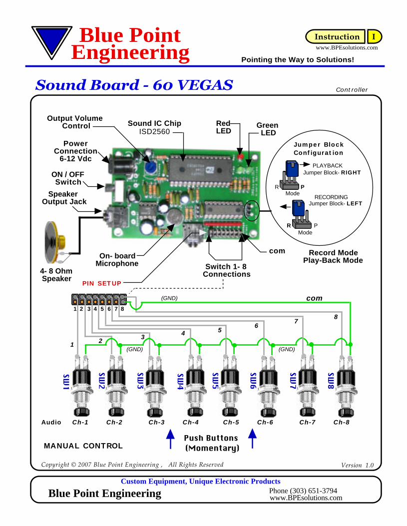
Connect a 4 or 8 ohm speaker to the audio speaker jack. (Minimum impedance 4 ohms. Maximum audio power is approximately 250 mWatts into an 8 ohm speaker).
Eight ( 8 ) pairs of duo pins may be connected to a number of remote switches. The switches should be momentary type that "Close Contact" when pressed. The switch pins towards the edge of the board is connected to electrical ground. (GND, Com) (See drawings for more details)( Hint: Use a duo 8 pin header and wire connector for easy connection of switches, sensors, etc. )
The Sound Board requires a 6-12V DC supply to work satisfactorily. In standby mode (example; not recording or replaying a message) current consumption of the sound board is approximately 900 mA. Connect a 6-12 Vdc 1-Amp power supply to the power jack.
( Caution: observe power connection points (+/-), board could be damaged if connected with wrong polarity. Center pin on power jack is positive )
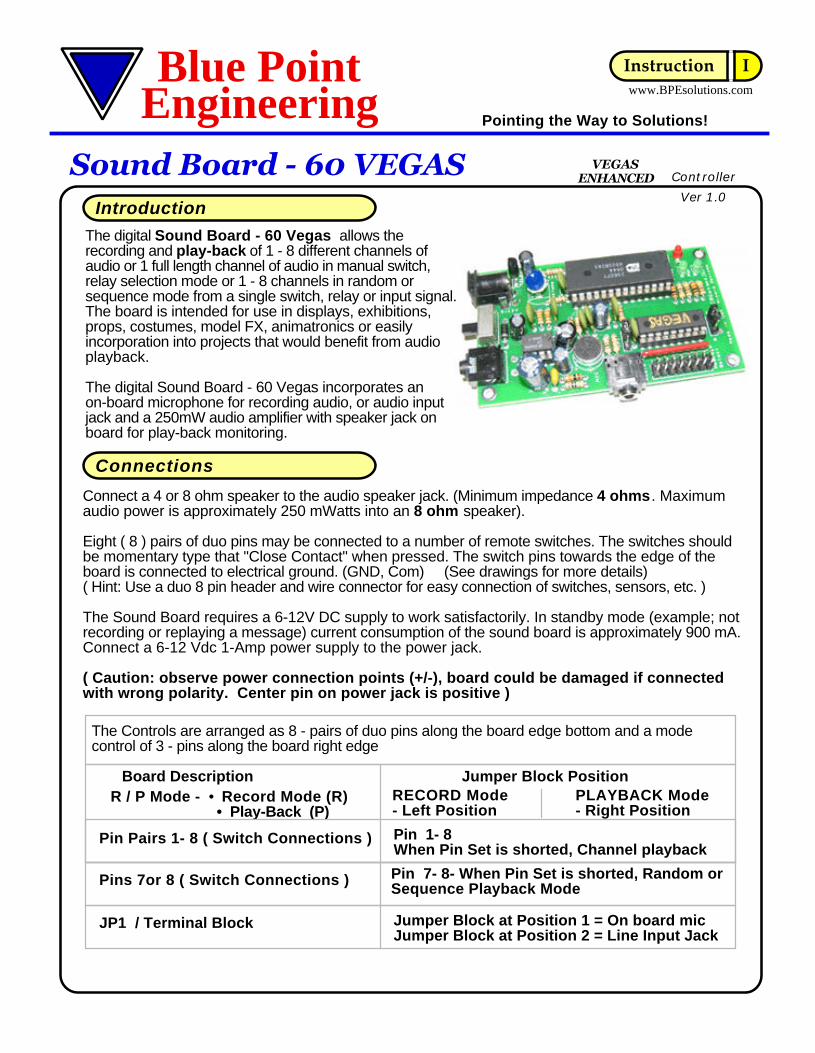
The digital Sound Board - 60 Vegas allows the recording and play-back of 1 - 8 different channels of audio or 1 full length channel of audio in manual switch, relay selection mode or 1 - 8 channels in random or sequence mode from a single switch, relay or input signal. The board is intended for use in displays, exhibitions, props, costumes, model FX, animatronics or easily incorporation into projects that would benefit from audio playback.
The digital Sound Board - 60 Vegas incorporates an on-board microphone for recording audio, or audio input jack and a 250mW audio amplifier with speaker jack on board for play-back monitoring.
Introduction
Connections
RECORD Mode- Left Position
Board Description Jumper Block PositionR / P Mode - • Record Mode (R) • Play-Back (P)
PLAYBACK Mode- Right Position
The Controls are arranged as 8 - pairs of duo pins along the board edge bottom and a mode control of 3 - pins along the board right edge
Pin 1- 8When Pin Set is shorted, Channel playback
Pins 7or 8 ( Switch Connections )
Ver 1.0
VEGASENHANCED
Jumper Block at Position 1 = On board micJumper Block at Position 2 = Line Input Jack
JP1 / Terminal Block
Pin Pairs 1- 8 ( Switch Connections )
Pin 7- 8- When Pin Set is shorted, Random or Sequence Playback Mode

Controller
Instruction IBlue Point Pointing the Way to Solutions!Engineering www.BPEsolutions.com
Sound Board - 60 VEGAS
Recording - Multiple Channels ( 1- 8 ) for Manual Switch or Relay ControlThe operating mode of the on board ISD sound chip is such that all audio has to be recorded consecutively during the same recording session. It is not possible to edit one message on its own- all messages must be re-recorded if one message needs to be changed.
Place JP1 - Set jumper block to the on-board Mic or Line Input position
Place the R/P Mode jumper block in the R position to enter record mode. (Jumper Installed - Left )Press Switch 1 connected to the switch pin pair set 1 (or place a shorting block between pin pair set 1). Hold down the connected switch or leave shorting block on pin pair-1 while speaking, or playing audio into the microphone. If you are using the Audio Input line jack and audio cable, then start the audio source your are sending sound from (Computer, CD player, iPod, ect).
The Red LED will turn ON and the board will continue to record while switch 1 is pressed, or the shorting block is on pin pair -1. At the end of the first audio recording, release the switch or remove the shorting block on pin pair -1.
To record the second message, press and hold switch 1 again or place a shorting block between pin pair set -1 again and speak into the microphone, or start the audio sound source. At the end of the second audio recording, release the switch or remove the shorting block on pin pair -1.
Continue adding audio as above until 8 messages have been recorded or the length of the messages exceeds the total recording time. ( 60 seconds total )
To end the entire recording session, remove the R/P Mode jumper from R side to the P terminal side.
If recording normal speech, it should be possible to obtain a good recording by speaking at anormal volume level about 30 - 50cm from the microphone. Take care to avoid mechanical switchnoise from switches 1-8, this could be recorded and played back as a loud click!
Note: The volume control is not used during recording.
Recording - Single Channel (1)In the single channel audio mode, sound is recorded as one long sound file up to 60 seconds.Channel -1 is used to record and playback the single audio only.
Place the R/P Mode jumper block in the R position to enter record mode. (Jumper Installed - Left )Press switch -1 (or place a shorting block between pin pair set -1). Hold down the connected switch or leave shorting block on pin pair-1 while speaking or playing audio into the microphone, or start the audio sound source. The Red LED will turn ON and the board will continue to record while the switch is pressed, or the shorting block is on pin pair -1. At the end of the audio recording, release the switch or remove the shorting block on pin pair -1.
To end the recording session, remove the R/P Mode jumper from R side terminals and move it over to the P side terminals.
Custom Equipment, Unique Electronic ProductsPhone (303) 651-3794www.BPEsolutions.comBlue Point Engineering
Operation
Ver 1.0

Recording - Multiple Channels ( 1- 8 ) for Sequential or Random ModeThe operating mode of the on board ISD sound chip is such that all audio has to be recorded consecutively during the same recording session. It is not possible to edit one message on its own- all messages must be re-recorded if one message needs to be changed.
Note: Not all 8 channels need to be used in the Sequential or Random Mode. You can do any number of channels from 1 through 8. The controller board will playback the number of channels you record in the Sequential or Random Mode.
Make sure that the jumper block is removed from pin pair 7 or pin pair 8.
Place the R/P Mode jumper block in the R position to enter record mode. (Jumper Installed - Left )
Press the connected switch (1) (or place a shorting block between pin pair set -1). Hold down the connected switch or leave shorting block on pin pair-1 while speaking or playing audio into the microphone. The Red LED will turn ON and the board will continue to record while the switch is pressed, or the shorting block is on pin pair -1. At the end of the first audio recording, release the switch or remove the shorting block on pin pair -1.
To record the second message, press and hold switch (1) or place a shorting block between pin pair set -1 again and speak into the microphone. At the end of the second audio recording, release the switch or remove the shorting block on pin pair -1.
Continue adding audio as above until the numbe of messages needed have been recorded or the length of the messages exceeds the total recording time. ( 60 seconds total ) or you have reached 10 Max individual recorded messages.
To end the entire recording session, remove the R/P Mode jumper from R side to the P terminal side.
If recording normal speech, it should be possible to obtain a good recording by speaking at anormal volume level about 30 - 50cm from the microphone. Take care to avoid mechanical switchnoise from switcheh - 1 as this could be recorded and played back as a loud click!
Note: The volume control is not used during recording.
To end the recording session, remove the R/P Mode jumper from R side terminals and move it over to the P side terminals.
The sound board is now ready to be operated in the Random or Sequential mode.(See playback for details)
www.BPEsolutions.com
Controller
Instruction IBlue Point Pointing the Way to Solutions!Engineering
Sound Board - 60 VEGAS
Copyright © 2007 Blue Point Engineering , All Rights Reserved
Ver 1.0
Enhanced
Operation - Cont.
Custom Equipment, Unique Electronic ProductsPhone (303) 651-3794Blue Point Engineering www.BPEsolutions.com
Recording for Sequential or Random Playback Mode

www.BPEsolutions.com
Controller
Instruction IBlue Point Pointing the Way to Solutions!Engineering
Sound Board - 60 VEGAS
Copyright © 2007 Blue Point Engineering , All Rights Reserved
Ver 1.0
Custom Equipment, Unique Electronic ProductsPhone (303) 651-3794Blue Point Engineering www.BPEsolutions.com
Sequential or Random Playback Mode
Troubleshooting S / R Mode
Recorded messages do not conform to the intended number sequence.If you expected audio from channel - 4 and obtained audio from channel - 5 or another channel, this could be due to switch contact problem when recording. The contacts of the switch have "bounced" and introduced an additional (blank) message. Re-Record audio, taking care not to double press or bounce the switch when pressed. NOTE: The jumper block across the jumper pins can also create a false switch effect, use care when moving the jumper blocks across the pins.
In the sequence mode, there is appears to be more time between the last recorded channel playback and the start of channel 1 or the time between each channel 2 - 8.This is probably due to switch "bounced" which introduced an additional (blank) message channel past the last channel 8.The sound board is playing those blank messages that it thought were recorded, because of the switch bounce. Re-Record audio, taking care not to double press or bounce the switch past 8.
Last message is truncated or missingCheck to see if you exceeded the total recording time for the sound chip. (60 seconds total)Or you switched on or off the board in record mode while recording audio.
Sound / message is truncated on playbackThe SB 60 VEGAS is designed with an instant ON and OFF playback mode. The sound will only playback as long as the switch is activated for that playback channel. If the switch is de-activated during playback the sound will stop immediately. Activate the switch for the length of sound neded to be played back.
I am trying to change sound channel - 8 to a new sound, but it will not record?All channels must be recorded within the same session - it is not possible for example to change only channel - 2 as a single recorded session only. All sound channels must be recorded during the same session, starting at sound channel -1 and completing at sound channel 8 (Random or sequence Mode selection) Note: Not all 8 channels need to be used in the Sequential or Random Mode. You can do and number of channels from 1 through 8. The controller board will playback the number of channels you record in the Sequential or Random Mode just as long as they were recorded in the same session.
No or broken audio in Random or Sequential Playback modeYou didn’t set the playback - Record jumper to the playback position before powering down.Place the jumper into the P position after recording and before powering down.
In the sequence mode, there is blank messages or sound past channel 8This is probably due to switch "bounced" which introduced an additional (blank) message channel past the last channel 8.The sound board - 60 is playing those blank messages that were recorded, because of the switch bounce. Re-Record audio, taking care not to double press or bounce the switch past 8. NOTE: The jumper block across the jumper pins can also create a false switch effect, use care when moving the jumper blocks across the pins.
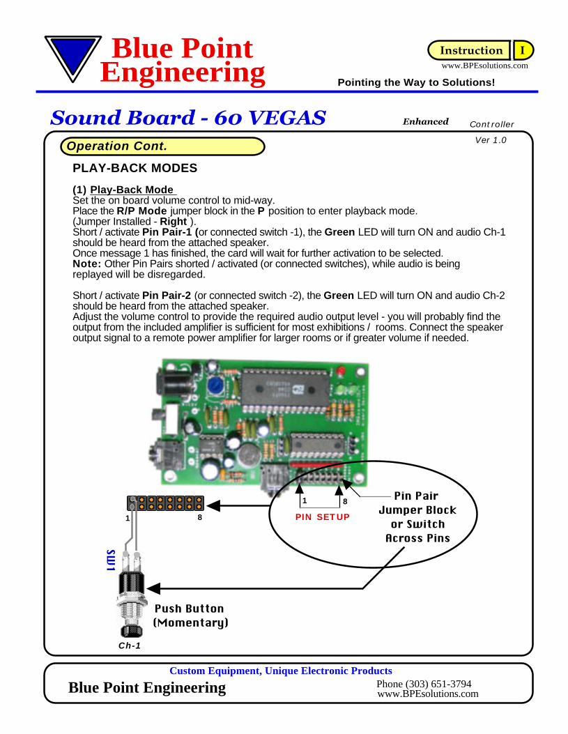
PLAY-BACK MODES
(1) Play-Back Mode Set the on board volume control to mid-way.Place the R/P Mode jumper block in the P position to enter playback mode.(Jumper Installed - Right ).Short / activate Pin Pair-1 (or connected switch -1), the Green LED will turn ON and audio Ch-1 should be heard from the attached speaker.Once message 1 has finished, the card will wait for further activation to be selected.Note: Other Pin Pairs shorted / activated (or connected switches), while audio is being replayed will be disregarded.
Short / activate Pin Pair-2 (or connected switch -2), the Green LED will turn ON and audio Ch-2 should be heard from the attached speaker.Adjust the volume control to provide the required audio output level - you will probably find theoutput from the included amplifier is sufficient for most exhibitions / rooms. Connect the speaker output signal to a remote power amplifier for larger rooms or if greater volume if needed.
www.BPEsolutions.com
Controller
Instruction IBlue Point Pointing the Way to Solutions!Engineering
Sound Board - 60 VEGAS
Custom Equipment, Unique Electronic ProductsPhone (303) 651-3794Blue Point Engineering www.BPEsolutions.com
Operation Cont.
Enhanced
Ver 1.0
PIN SETUP
Pin Pair Jumper Block
or SwitchAcross Pins
Push Button (Momentary)
SW1
1
Ch-1
1 8
8

Troubleshooting
Recorded messages do not conform to the intended number sequence.If you expected audio from channel - 3 and obtained audio from channel - 2, this could be due to dirty switch contacts when recording- the contacts have "bounced" and introduced an additional (blank) message. Re-Record audio, taking care not to double press or bounce the switch.
Last message is truncated or missingCheck to see if you exceeded the total recording time for the sound chip. (20 seconds total)
Messages appear to contain a lot of background noiseThe on-board microphone and control circuit are very sensitive - try to record under very quietconditions, away from items that cause electrical noise, florescent lights, speaker magnets, motor, etc.
Playback volume is distortedIf you're using a small un-mounted speaker, try replacing a larger, boxed in type speaker unit.( 4 or 8 Ohm speaker )Adjust the volume control to provide the required audio output level - you will probably find theoutput from the included amplifier is sufficient for most exhibitions / rooms. Connect the speaker output signal to a remote power amplifier for larger rooms or if greater volume if needed.
How can I erase the sound chip?Recording a new set of sounds, is really the only way to full erase the chip, but you can clear the sound channels without recording over it, by trying the following:Set the Mode jumper to R ( record ) the RED LED will turn ON.Short together pin pair - 1 on and off 8 times, this will re-program the sound chip with a very quick white noise signal on each channel, if played back.
I am trying to change sound channel - 4 to a new sound, but it will not record?All channels must be recorded within the same session - it is not possible for example to change only channel - 2 as a single recorded session only. All sound channels must be recorded during the same session, starting at sound channel -1 and completing at sound channel - 8.
HINT: Pre-organize your sound data to be recorded in sequence format for quick easy recording.
Sound / message is truncated on playbackThe SB may be a modified version SB60EV with an instant ON and OFF playback mode. The sound will only playback as long as the switch is activated for that playback channel. If the switch is de-activated during playback the sound will stop immediately. Activate the switch for the length of sound neded to be played back.
www.BPEsolutions.com
Controller
Instruction IBlue Point Pointing the Way to Solutions!Engineering
Sound Board - 60 VEGAS
Custom Equipment, Unique Electronic ProductsPhone (303) 651-3794Blue Point Engineering www.BPEsolutions.com
Copyright © 2004 Blue Point Engineering , All Rights Reserved
Ver 1.0
SW1

Wall Plug Power SupplyRegulated 9 Vdc @ 900 mA
www.BPEsolutions.com
Controller
Instruction IBlue Point Pointing the Way to Solutions!Engineering
Sound Board - 60 VEGAS
Custom Equipment, Unique Electronic ProductsPhone (303) 651-3794Blue Point Engineering www.BPEsolutions.com
Copyright © 2007 Blue Point Engineering , All Rights Reserved
Sound Recording Playback
Speaker
Wire
Wire
Soun
d IC
Chi
p
Power
Audio Input - Mic or Audio Line Jack
Sound Source
Version 1.0
OR
Sound INPUT
CD Player
ComputerSound Port
OR
Microphone
OR
Audio Cable
OR1V p-p
Jumper BlockConfiguration
Mic Input
Audio Line Input
(1)(C)(2)
Speaker and Amplifier
PLAYBACK
Large VolumeSound Output
(Mono Output)
OR
Large Volume
ORRecord Mode
Play-Back Mode
PLAYBACK
RECORDING
Jumper Block- RIGHT
Jumper Block- LEFT
PR
PR
Jumper BlockConfiguration
Mode
Mode
9 Vdc @ 800 mA
+ Vdccenter
- Vdc
2.1
mm
C
onne
ctor
Regulated Power
- Vdcoutside
+ Vdc
center Red
Black
outside
Playback
PowerOn / Off Mono
Audio Cable
8
PowerConnection
www.BPEsolutions.com
Controller
Instruction IBlue Point Pointing the Way to Solutions!Engineering
Sound Board - 60 VEGAS
Custom Equipment, Unique Electronic ProductsPhone (303) 651-3794Blue Point Engineering www.BPEsolutions.com
Speaker Output Jack
Record ModePlay-Back Mode
Switch 1- 8 Connections
Output Volume Control
6-12 Vdc
SW2
Push Buttons (Momentary)
SW3
SW1
PIN SETUP
SW5
SW6
SW4
SW7
SW8
1 2 3 4 5 6 7
Sound IC ChipISD2560
Red LED
Green LED
PLAYBACK
RECORDING
Jumper Block- RIGHT
Jumper Block- LEFT
PR
PR
Jumper BlockConfiguration
On- boardMicrophone
Mode
Mode
com
87
654
32
com(GND)
MANUAL CONTROL
Ch-1 Ch-2 Ch-3 Ch-4 Ch-5 Ch-6 Ch-7 Ch-8Audio
1(GND) (GND)
Wir
eWir
e
Wir
e
Wir
e
Soun
d IC
Chi
p
Ch-
7
Ch-
8
Copyright © 2007 Blue Point Engineering , All Rights Reserved
4- 8 Ohm Speaker
Version 1.0
ON / OFFSwitch
PO
WE
R

SW2
SW3
SW1
SW5
SW6
SW4
SW7
SW8
www.BPEsolutions.com
Controller
Instruction IBlue Point Pointing the Way to Solutions!Engineering
Sound Board - 60 VEGAS
Custom Equipment, Unique Electronic ProductsPhone (303) 651-3794Blue Point Engineering www.BPEsolutions.com
Copyright © 2007 Blue Point Engineering , All Rights Reserved Version 1.0
Ch-3
Prop
IR Sensor
Wir
eWir
e
Sound Recording(1) 0.2 - minute playback sound theme - A(2) 0.5 - minute playback sound theme - B(3) 0.3 - minute playback sound theme - C
Wir
e
Wir
e
IR SensorLocation A
Location B
IRRelay
ContactsIR
Relay Contacts
Ch-2
Soun
d IC
Chi
p
Pin Pair Terminal
Sound theme - B
Sound theme - C
Manual Switch
Ch - 1
Ch-1
Sound theme A
Manual / Automated Playback Example
Ch-
7
Ch-
8
Sound RecordingPlayback
Speaker Playback
Audio Cable (Mono)
POWER
PO
WE
R

SW2
SW3
SW1
SW5
SW6
SW4
SW7
SW8
Wir
eWir
e
Wir
e
Wir
e
Soun
d IC
Chi
p
www.BPEsolutions.com
Controller
Instruction IBlue Point Pointing the Way to Solutions!Engineering
Sound Board - 60 VEGAS
Custom Equipment, Unique Electronic ProductsPhone (303) 651-3794Blue Point Engineering www.BPEsolutions.com
Copyright © 2007 Blue Point Engineering , All Rights Reserved Version 1.0
Speaker and Amplifier
PLAYBACK
Audio Cable
Large Volume
OR
REMOTE SENSOR• Floor Mat Switch.• PIR Sensor. • Manual Operated Switch.• Relay Contact Switch, etc.
8 - Channel Automated Playback Example6Ch - Sound and 2Ch - Prop Control
Ch-6Ch-5Ch-4Ch-3
Wizard - 2 Programmable Controller Board
Or Wizard- 4 Board (4 ch)
Pin Pairs 1-6
Ch-2Ch-1
Prop
Ch - 7 and Ch - 8To Mechanical Control Device
in Prop
Wizard -2 Board
Ch-
7
Ch-
8
Ch-7Ch-8
Not Used
Sound RecordingPlayback
Speaker Playback
Audio Cable (Mono)
PO
WE
R

www.BPEsolutions.com
Controller
Instruction IBlue Point Pointing the Way to Solutions!Engineering
Sound Board - 60 VEGAS
Custom Equipment, Unique Electronic ProductsPhone (303) 651-3794Blue Point Engineering www.BPEsolutions.com
Copyright © 2007 Blue Point Engineering , All Rights Reserved
Ver 1.0Sequential Playback Mode
Jumper BlockConfiguration
PIN SETUP
7
7
Pin Pair Jumper Block
Sequential Playback
Pin Pair - 7
Turn OFF power supply, or remove power connector from board.Place a jumper block over Pin Pair-7 (This configuration will be read at power up and will put the board into the sequential playback mode).Power up the board (Turn ON power).Short / activate Pin Pair- 1 (or switch, relay) This will playback channel -1. Short / activate Pin Pair-1 again at the end of playback channel -1, the board will now playback channel- 2.Repeat - Short / activate Pin Pair-1 for each additional channe 3 - 8. When channel - 8 is reached, cycle will restart at channel -1.
Push Button (Momentary)
SW1
1
Ch-1
SW1
Note: Not all 8 channels need to be used in the Sequential or Random Mode. You can record any number of channels from 2 through 8. The controller board will playback the number of channels you record in the Sequential or Random Mode. See operation section for more details.

www.BPEsolutions.com
Controller
Instruction IBlue Point Pointing the Way to Solutions!Engineering
Sound Board - 60 VEGAS
Custom Equipment, Unique Electronic ProductsPhone (303) 651-3794Blue Point Engineering www.BPEsolutions.com
Copyright © 2007 Blue Point Engineering , All Rights Reserved
SW1
Random Playback Mode
Jumper BlockConfiguration
PIN SETUP
8
8
Pin Pair Jumper Block
Random Playback
Pin Pair - 8
Turn OFF power supply, or remove power connector from board.Place a jumper block over Pin Pair-8 (This configuration will be read at power up and will put the board into the random playback mode).Power up the board (Turn ON power).Short / activate Pin Pair-1 (or switch, relay) This will randomly playback channel -1 through channel - 8Short / activate Pin Pair-1 again at the end of playback, the board will now randomly playback channel -1 through channel - 8 again. Repeat for random channel playback.
Push Button (Momentary)
SW1
1
Ch-1
Ver 1.0
Note: Not all 8 channels need to be used in the Sequential or Random Mode. You can record any number of channels from 2 through 8. The controller board will playback the number of channels you record in the Sequential or Random Mode. See operation section for more details.