blue range brochure a/w (page 2) - audio … focusrite mastering solution. since the earliest days...
TRANSCRIPT

Focusritea u d i o e n g i n e e r i n g
Blue RangeTHE COMPLETE MASTERING STUDIO
Blue 315 Isomorphic Mastering Equaliser
Blue 330 Mastering Compressor/Limiter
Blue 260 24-Bit D–A Convertor
Blue 245 20 Bit A–D Convertor
Blue 300 Mastering Controller
The Focusrite Mastering Solution.
Since the earliest days of vinyl, the mastering process has
been critical to the successful transfer of recordings to the
delivery medium. Today the Compact Disc is the primary
medium but Compact Cassette and Vinyl discs are still in
demand and the mastering engineer will often be asked to
master for all three formats plus limited editions for AM
and FM broadcast.
The source material may be old or new; recordings in
analogue or digital formats and of varying overall quality and
bandwidth. The task is to edit and process the recordings
to extract the best possible master for the given delivery
medium, taking into account the limitations of that medium.
Digital Audio Workstations (DAW’s) are replacing
analogue transfer consoles used in previous decades.
However there is no standard approach to system design
within the mastering rooms around the world; typically
each engineer has accumulated his chosen selection of
equipment with a custom solution to monitoring signals at
different stages.
From the experienced gained from supplying some of
the world’s leading mastering facilities with dedicated
Mastering Equalisers and Compressor / Limiters,
Focusrite has developed a unique product to tie all the
elements together, the Blue 300 Mastering Controller.
With the addition of 20-bit A/D and 24-bit D/A convertors
to the Blue Mastering Range, Focusrite is the only company
to offer the complete mastering solution - just add your
choice of Workstation!
What makes Focusrite Mastering Products so special?
Focusrite is renowned for the highest quality equalisers
and dynamics processors for music recording so what
could be more logical than to extend that technology to
the special requirements of the mastering engineer.
Focusrite’s rigorous approach to designing both
analogue and digital circuitry results in the highest
possible signal integrity with very low noise, distortion and
wide analogue frequency bandwidth.
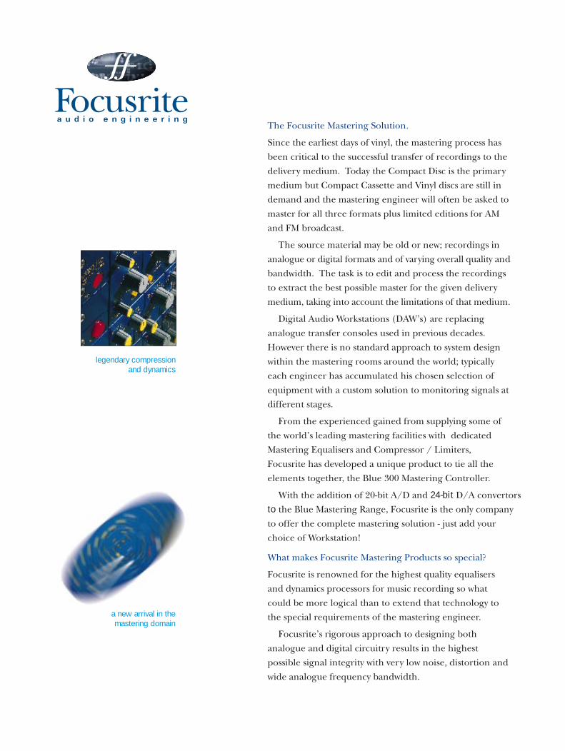
legendary compression and dynamics
a new arrival in the mastering domain

4
6
10
11
12
8
All the rotary controls on the Blue 315 MasteringEqualiser and Blue 330 Mastering Compressor are highquality gold plated switches, for quiet and long lifeoperation, not potentiometers as used in conventionalproducts. They switch the signal between accuratelycalibrated electronic circuits to ensure channel to channelmatching and most importantly to achieve repeatability.Amplitude is adjusted in as little as 1/3dB steps.
The mastering process should add nothing to thesound of the recording which is not consciously desired bythe mastering engineer. Therefore noise and distortionartefacts are negligible whilst the functions of theprocessors deliver predictable, sonically enhancing results.
Why do I need analogue processing?
If the recording is analogue you may choose to process itin the analogue domain before converting it to a digitalformat for editing. However many engineers using DAW’slike to convert back to analogue for EQ and Compressionbecause of the results they can only achieve with analogueprocessors, then reconvert to digital for editing, whetherthe source recording was analogue or digital. Focusrite20-bit convertors have been designed to ensure that thisprocess is completely transparent.
How can I find out more about Focusrite Mastering?
You can contact Focusrite by phone, fax or Email orcontact your local Focusrite Distributor. We will be
delighted to arrange for theproducts to be made available toyou for evaluation in your facility.
Blue 315 Isomorphic Mastering Equaliser
The ultimate mastering equaliser
Blue 330 Mastering Compressor/Limiter
Unrivalled precision and performance
in dynamic control
Masterplan : System Schematic
The creative possibilities of
the Focusrite Blue Range
Blue 260 24 Bit D–A Convertor
The highest quality outboard
Digital to Analogue
Blue 245 20 Bit A–D Convertor
The highest quality outboard
Analogue to Digital
Blue 300 Mastering Controller
Complete routing and
monitoring control
the complete mastering solution

Blue 315Isomorphic Mastering Equaliser The ultimate mastering equaliser
The Blue 315 offers the renowned smoothness and
musicality of the Focusrite EQ in a form optimised for
the mastering suite. The result is the ultimate mastering
equaliser, capable of both creative sweetening and
effectively removing troublesome frequencies without
unduly affecting the rest of the signal.
There are two channels of 4-band EQ circuitry - two
fully parametric mid bands and two fully parametric
bands for low and high frequencies which can also be
switched to shelving mode. The bass end EQ stage can
also operate over an extended frequency range for very
low end control for film or dance music applications.
Additional high and low pass filters are
included for out of band correctional EQ work.
All EQ stages are based on circuit topologies
employed in the Focusrite Studio Console with
the added sensitivity, accuracy and control required for
4

mastering applications. The extremely broad frequency
response of the Blue 315 - from 5Hz to 140kHz,
guarantees smooth frequency and phase response across
the much narrower range of human hearing.
Large control knobs on the Blue 315’s clearly laid out
facia allow easy adjustment of the switches controls and
make it simple to check EQ settings at a
glance. The four fully parametric bands feature
wide, overlapping frequency ranges. Each
offers switching between two frequency ranges,
allowing precise frequency selection via rotary switches
across the full bandwidth.
Q is variable over an unusually wide range of 0.4 to 2.4, in
11 discrete steps, with the cut/boost control designed to
offer finer control around the null point with larger steps
at the extremities.
Precise I/P level control is assured with three separate
gain controls for each channel - rotary switches for
coarse and fine gain control and a continuously variable
trim control.
Thanks to buffering between sections, all EQ bands
operate independently and are not affected by any of the
other bands.
[For full specifications, please see back page.]
51 5 6
2 3 4 12 13 14 15
7 8 9 1110
C O N T R O L F U N C T I O N S BLUE 315
1 Link switch: Allows the push button functions in both EQ sections to be operated simultaneously fromeither channel.
2 EQ In switch: Operates on all EQ sections. A quickpress turns on the EQ, another quick press turns off theEQ. When held down the EQ is turned on until releasedwhereby the EQ is turned off, this allows quickcomparisons between EQ’ed and non EQ’ed sounds.
3 O/load indicator: Illuminates 6dBu below circuitoverload takes place.
4 Ø switch: Inverts the phase (180˚) of the output ofthe channel.
Rotary filter switches: Maybe switched out in the verticalposition or set to the frequencies indicated.
5 High pass filter: 12dB/octave at 33, 47, 68, 100 and 150Hz.
6 Low pass filter: 12dB/octave at 10, 12, 15, 18 and 22kHz.
7 Q rotary switch: Controls the bandwidth offrequencies effected around the centre frequency. LowQ=0.4, high Q=2.4.
8 Low Frequency switch: Selects the centre frequencyat which the effects will take place; Low range 20, 26, 33,39, 47, 56, 68, 82, 100, 120 and 180 Hz. High range 100, 130, 150, 180, 220, 260, 330, 390, 480,590 and 770Hz.
9 Amplitude rotary switch: Boosts or cuts theamplitude at the centre frequency by up to 10dB, withincreased sensitivity around 0dB.
10 Hi range switch: Shifts the operating frequency of therotary frequency switch into a higher range of frequencies.
11 Bell/Shelf switch: Converts the low and highparametric sections from bell filters to shelf filters, when inthis configuration the Q control effects the resonance andthe roll off slope of the filter.
12 Low Mid Frequency switch: Selects the centrefrequency at which the effects will take place; Low range39, 47, 56, 68, 82, 100, 120, 150, 180, 220 and 270 Hz.High range 180, 220, 270, 330, 390, 470, 560, 680,820, 1k and 1k2Hz .
13 High Mid Frequency switch: Selects the centrefrequency at which the effects will take place; Low range 560, 680, 820, 1k, 1k2, 1k5, 1k8, 2k2, 2k7,3k3 and 3k9 Hz. High range 2k7, 3k3, 3k9, 4k7, 5k6,6k8, 8k2, 10k, 12k, 15k and 18kHz .
14 High Frequency switch: Selects the centre frequencyat which the effects will take place; 3k3, 3k9, 4k7, 5k6,6k8, 8k2, 10k, 12k 18k, and 22kHz.
15 Input gain controls:+10/-15dB rotary switch adjust theinput gain in 5dB steps. ±2.5dB rotary switch adjusts theinput gain in 0.5dB steps. ±1dB vari potentiometer allowscontinuous adjustment of the input gain, when enabled.Vari in switch enables the use of the vari potentiometer.

Blue 330Mastering Compressor Limiter Unrivalled precision and performance in dynamic control
The Blue 330, employing Focusrite’s unique single-VCA
circuit design, offers unrivalled precision and
performance in dynamic control in a mastering suite.
All rotary controls are multi-position precision switches,
allowing accurate recall of previous settings.
Very accurate PPMs, switchable to measure gain
change, input or output level, offer dual scale operation
that allows accurate measurement of a wide range of peak
signals. Thanks to the broad range of the threshold
control and Focusrite’s proprietary circuitry, the Blue 330
can compress very high signal levels - up to +26dB
without distortion. The Limiter too, offers an
unusually wide threshold range.
The VCA used is a balanced class A design,
offering superb low noise distortion and
excellent common-mode rejection.
In order to separate compression and limiting, the
sidechain electronics contain three VCAs to generate
compression and limiting rather than the more common
characteristic of compression that turns into limiting.
The sidechain electronics utilise class A design
techniques, ensuring superb transient response. Both
compression and limiting therefore offer true peak
response, not averaging RMS response and control. 6
The use of high quality audio Class A VCA as the only
element between input and output means a very short
signal path, and an ability to retain a natural, unobtrusive
sound even when significant compression is being applied.
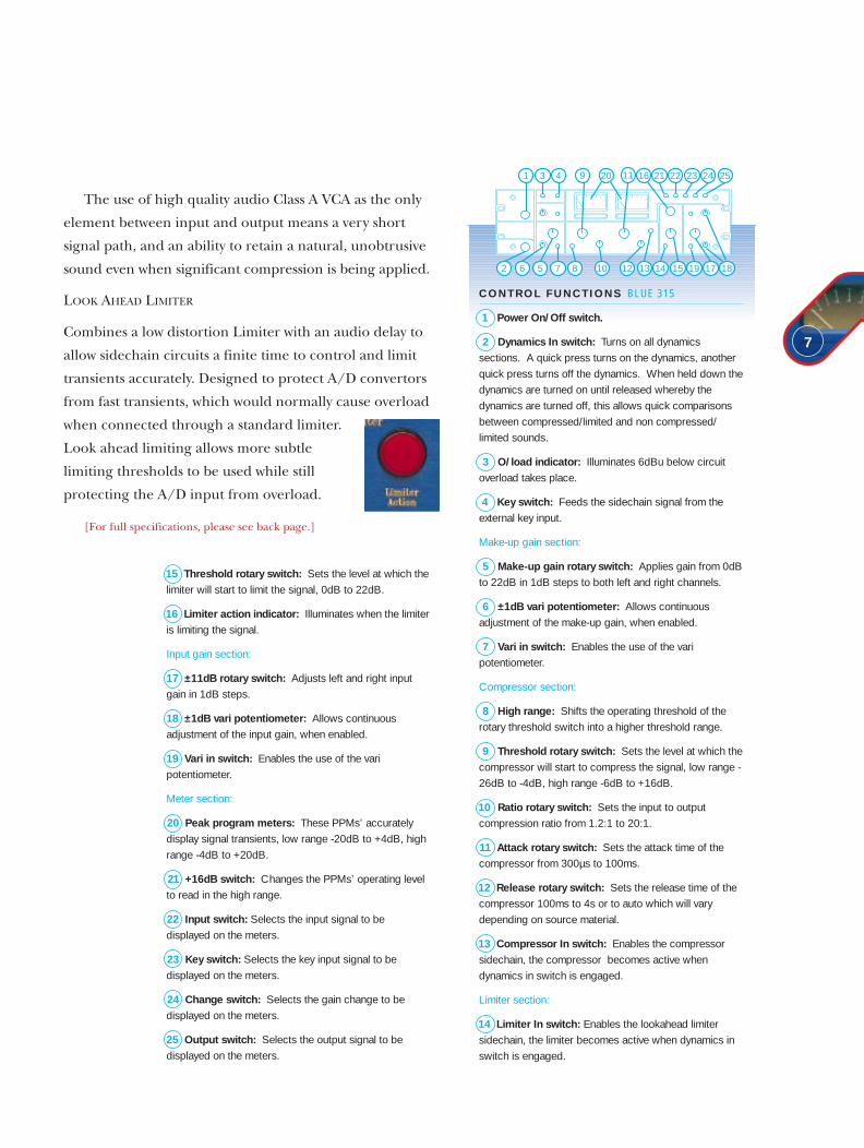
LOOK AHEAD LIMITER
Combines a low distortion Limiter with an audio delay to
allow sidechain circuits a finite time to control and limit
transients accurately. Designed to protect A/D convertors
from fast transients, which would normally cause overload
when connected through a standard limiter.
Look ahead limiting allows more subtle
limiting thresholds to be used while still
protecting the A/D input from overload.
[For full specifications, please see back page.]
7
C O N T R O L F U N C T I O N S BLUE 315
1 Power On/Off switch.
2 Dynamics In switch: Turns on all dynamicssections. A quick press turns on the dynamics, anotherquick press turns off the dynamics. When held down thedynamics are turned on until released whereby thedynamics are turned off, this allows quick comparisonsbetween compressed/limited and non compressed/limited sounds.
3 O/load indicator: Illuminates 6dBu below circuitoverload takes place.
4 Key switch: Feeds the sidechain signal from theexternal key input.
Make-up gain section:
5 Make-up gain rotary switch: Applies gain from 0dBto 22dB in 1dB steps to both left and right channels.
6 ±1dB vari potentiometer: Allows continuousadjustment of the make-up gain, when enabled.
7 Vari in switch: Enables the use of the varipotentiometer.
Compressor section:
8 High range: Shifts the operating threshold of therotary threshold switch into a higher threshold range.
9 Threshold rotary switch: Sets the level at which thecompressor will start to compress the signal, low range -26dB to -4dB, high range -6dB to +16dB.
10 Ratio rotary switch: Sets the input to outputcompression ratio from 1.2:1 to 20:1.
11 Attack rotary switch: Sets the attack time of thecompressor from 300µs to 100ms.
12 Release rotary switch: Sets the release time of thecompressor 100ms to 4s or to auto which will varydepending on source material.
13 Compressor In switch: Enables the compressorsidechain, the compressor becomes active whendynamics in switch is engaged.
Limiter section:
14 Limiter In switch: Enables the lookahead limitersidechain, the limiter becomes active when dynamics inswitch is engaged.
15 Threshold rotary switch: Sets the level at which thelimiter will start to limit the signal, 0dB to 22dB.
16 Limiter action indicator: Illuminates when the limiteris limiting the signal.
Input gain section:
17 ±11dB rotary switch: Adjusts left and right inputgain in 1dB steps.
18 ±1dB vari potentiometer: Allows continuousadjustment of the input gain, when enabled.
19 Vari in switch: Enables the use of the varipotentiometer.
Meter section:
20 Peak program meters: These PPMs’ accuratelydisplay signal transients, low range -20dB to +4dB, highrange -4dB to +20dB.
21 +16dB switch: Changes the PPMs’ operating levelto read in the high range.
22 Input switch: Selects the input signal to bedisplayed on the meters.
23 Key switch: Selects the key input signal to bedisplayed on the meters.
24 Change switch: Selects the gain change to bedisplayed on the meters.
25 Output switch: Selects the output signal to bedisplayed on the meters.
1
2 6 7 8
9
10
11
12 13 14 15 19 17 185
3 4 21 22 23 24 2520 16

Blue 26024 Bit D–A Convertor The highest quality outboard Digital to Analogue
The BLUE 260 24 Bit D/A Convertor from Focusrite has
been designed to provide the highest quality outboard
Digital to Analogue conversion for the world’s leading
Mastering, Broadcast and Post Production studios.
Utilising the latest Crystal 24 Bit Delta-Sigma
Convertor with a 128 x Interpolation filter, the BLUE 260
uses static logic in all its digital circuits (there are no DSP
circuits or processors) so that the convertor clock is the
only clock signal present on the board.
This technique removes a wide variety of digital
interference such as Hetrodyning, beating and “birdies”
and creates an analogue output signal that has an
exceptionally low noise floor and is free from digital
interference and crosstalk.
The BLUE 260 has been designed to complement the
very high performance of Focusrite’s BLUE 245 A/D
Convertor launched in 1996.
Features include 6 selectable digital inputs (4 x AES,
Optical and SPDIF) and a fully regenerated AES output
which follows the input selection.
In addition a logic link on the rear panel will allow
BLUE 260 to provide digital source selection for the
forthcoming Focusrite BLUE 300 Mastering Controller.
Front Panel Controls include Input
Format and AES Selection; sample rate and
status indication.
[For full specifications, please see back page.]
10
C O N T R O L F U N C T I O N S BLUE 260
1 Switch 1: Selects AES input 1.
2 Switch 2: Selects AES input 2.
3 Switch 3: Selects AES input 3.
4 Switch 4: Selects AES input 4.
5 Indicator 1: Illuminates when any of switches 1-4 are selected.
6 Optical switch: Selects optical input.
7 S/P switch: Selects S/PDIF input.
8 Indicator 32: Displays if a 32kHz sample rate is detected.
9 Indicator 44.1: Displays if a 44.1kHz sample rate is detected.
10 Indicator 48: Displays if a 48kHz sample rate is detected.
11 Error indicator: Displays if an error is detected (e.g.loss of clock data).
12 Lock indicator: Displays if the signal is locked.
13 Emphasis indicator: Displays if emphasis is detected.
1 2 3 4 5 6
7
8 9 12 13
1110

Blue 245Unparalleled fidelity in mastering, transfer and recording 20 Bit A–D Convertor
The Blue 245 has been designed to perform to the very
high standards established by Focusrite’s legendary
analogue processors, and provide unparalleled fidelity in
mastering, transfer and recording work - quite simply to be
the best sounding A-D convertor in the world.
By combining Focusrite’s traditional attention to
detail, and dedication to precision manufacturing
techniques, with the expertise of leading digital
design specialists, the Blue 245 comes closer to
achieving the potential of 20 bit conversion than any other
convertor, with superior noise (<-108dB THD+N) and
jitter (<1.6nS) performance.
Based around a precision 20 Bit 64x oversampling
delta-sigma chipset, every aspect of the Blue 245’s design is
optimised to achieve the best possible performance.
No signal processing is performed in the digital
domain for good reason.The use of microprocessors and
DSPs in a convertor calls for additional clocks that may not
be related to the sample frequencies which throws up the
problems of cross coupling of clocks into the ADC or
other analogue circuits.
Even when working to 16 bit media such as DAT, the 20 bit
245 brings substantial benefits thanks to a proprietary
TPDF (Triangular Probability Density Function)dithering
system that enables the 20 bit signal to pass into the 16 bit
domain with as much honesty as possible.
Combining the Blue 245 with the Blue 260 D/A
Convertor creates an outstanding package for entering and
leaving the digital domain. The Blue 245 is the last word in
A/D conversion from the first name in analogue processing.
[For full specifications, please see back page.]
11
C O N T R O L F U N C T I O N S BLUE 245
1 Input sensitivity potentiometer: Sets the analoguelevel coming into the unit.
2 Peak program meters: These PPMs’ accuratelydisplay signal transients and display overload at the far right.
Sample rate section: Allows the selection of differentsample rate for the conversion process.
3 External switch: Selects the external sample rateprovided on the rear panel.
4 32k switch: Selects 32kHz sample rate used mainlyfor broadcast.
5 44k1 switch: Selects 44.1kHz sample rate usedmainly for consumer replay.
6 48k switch: Selects 48kHz sample rate used mainlyfor professional record and replay.
Quantisation section
7 20 switch: Switches to 20 bit conversion withsingle bit dither.
8 16 switch: Switches to 16 bit conversion with 4 bit dither.
3 4 5 61 2
7 8

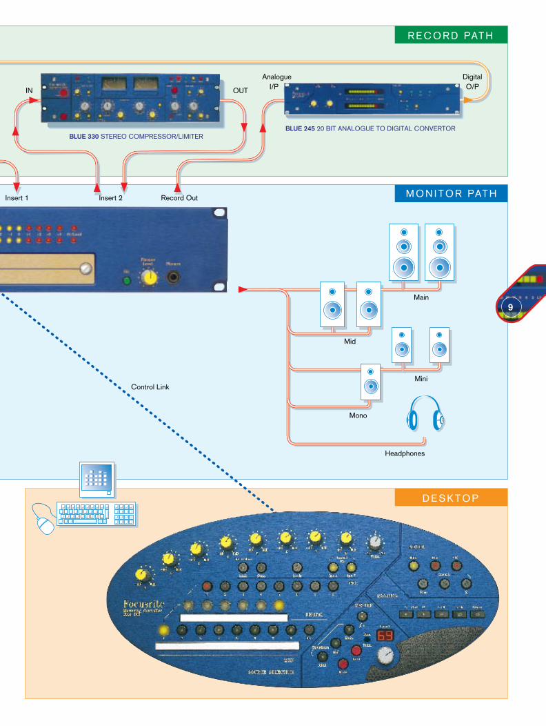
The schematic is broken down into fourareas:
SOURCE SELECTION AND ROUTING
RECORD PATH
MONITOR PATH
DESKTOP
In the SOURCE SELECTION ANDROUTING section, digital or analoguestereo record sources can be accessedusing the Blue 260 D/A Convertor (labelledRECORD PROCESSING LOOP) for thedigital sources and for the analogue
sources the Blue 300 Mastering Controller.
Using the Blue 300, the stereo recordsources can then be routed to theRECORD PATH using Inserts 1 & 2 topass through the Blue 315 IsomorphicEqualiser and Blue 330 StereoCompressor Limiter.
The output of the Blue 300’s RECORDPATH can the be fed to the BLUE 245 A/DConvertor to maintain extremely high signalintegrity with conversion of the stereoanalogue signal into the digital domain.
The digital outputs of the BLUE 245 can
then be fed to the last item in the RECORDPATH - the Digital Audio Workstation.
The digital outputs of the workstationreturn to SOURCE SELECTION ANDMONITORING and, using a Blue 260 D/AConvertor (labelled MONITOR) and theBlue 300 Mastering Controller, routed tothe chosen MONITOR PATH.
Finally, control of the Digital Audio Work-station and the Blue 300 Mastering Controllercan be made on the DESKTOP using thekeyboard and VDU for the Workstation andthe Blue 300’s unique oval remote panel.
This typical system schematic has been created to illustrate the creative possibilitiesand design concepts of the Focusrite Mastering Solution.
9

Blue 300Mastering Controller Complete routing and monitoring control
The Focusrite BLUE 300 Mastering Controller has been
developed in response to a growing requirement for
high quality routing and monitoring control in the
mastering facility.
The BLUE 300 provides a comprehensive package
which includes analogue and digital source selection,
precision monitor control with speaker and headphone
selection, record path routing with inserts and high
quality stereo VU metering.
Its unusual design approach uses an oval shaped remote
panel connected to a 2U master module. This gives the
BLUE 300 physical benefits of a free-standing control
surface with the sonic benefits of an audio path optimised
for wide bandwidth, low noise, low distortion and crosstalk.
The BLUE 300 has eight stereo analogue inputs which
can be selected onto two independent stereo signal paths
- the Record Path and the Monitor Path.
In addition to the analogue inputs, 6 x digital inputs can
be added to the BLUE 300 using the Focusrite BLUE 260
Digital to Analogue convertor.
The Remote panel is divided into four sections Source
Selection, Meter, Monitor and Master.
12

S O U R C E S E L E C T I O N
The Source Selection section on the left hand sidehouses the controls for the input selection.
There is also a fader level control for each ofthe 8 inputs which, at the anti-clockwise end of thefader travel, is calibrated to a 0dB setting.
The faders can be used in conjunction with theSum switch in the record path to combine twosignals together - for example combining an effectsuch as reverberation with its original stereo signal.
Each fader uses a stepped resistor networkwhich provides a sonically transparent and smoothfade between 0db to -40dB.
There is also a similar trim control fader for theRecord Path output; this provides +/- 10dB of gainor attenuation.
Input 1 of the BLUE 300 is designated as theDigital Source Input; which, using the the 6 xDigital source selection buttons, can control theinput selection of a Blue 260 D/A Convertor.(4xAES, Optical and SPDIF).
Insert 1 and 2 In switches allow other devices tobe inserted into the record path. These inserts can
be used for inserting analogue processing such asFocusrite’s BLUE 315 Isomorphic Equaliser orBLUE 330 Stereo Compressor.
M O N I T O R
The Monitor section controls the monitor outputformat, for checking the compatibility of stereosignals.
M A S T E R
The Master section houses the Main Monitor controlswhich include Mute, Dim, Speaker Select and a largemonitor level control. An LED display is includedfor accurate and repeatable monitoring levelswhich can be recalled between sessions.
13
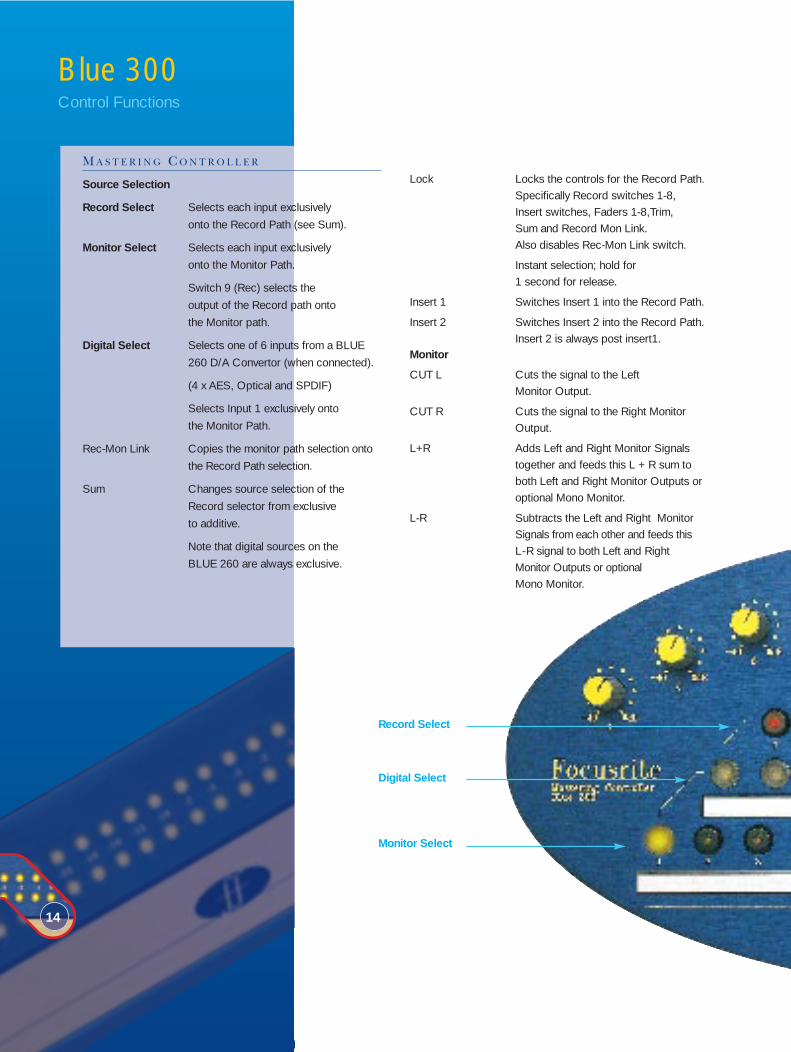
Lock Locks the controls for the Record Path. Specifically Record switches 1-8, Insert switches, Faders 1-8,Trim, Sum and Record Mon Link. Also disables Rec-Mon Link switch.
Instant selection; hold for 1 second for release.
Insert 1 Switches Insert 1 into the Record Path.
Insert 2 Switches Insert 2 into the Record Path. Insert 2 is always post insert1.
Monitor
CUT L Cuts the signal to the Left Monitor Output.
CUT R Cuts the signal to the Right Monitor Output.
L+R Adds Left and Right Monitor Signals together and feeds this L + R sum to both Left and Right Monitor Outputs or optional Mono Monitor.
L-R Subtracts the Left and Right Monitor Signals from each other and feeds this L - R signal to both Left and Right Monitor Outputs or optional Mono Monitor.
Blue 300 Control Functions
14
M A S T E R I N G C O N T R O L L E R
Source Selection
Record Select Selects each input exclusively
onto the Record Path (see Sum).
Monitor Select Selects each input exclusively
onto the Monitor Path.
Switch 9 (Rec) selects the
output of the Record path onto
the Monitor path.
Digital Select Selects one of 6 inputs from a BLUE
260 D/A Convertor (when connected).
(4 x AES, Optical and SPDIF)
Selects Input 1 exclusively onto
the Monitor Path.
Rec-Mon Link Copies the monitor path selection onto
the Record Path selection.
Sum Changes source selection of the
Record selector from exclusive
to additive.
Note that digital sources on the
BLUE 260 are always exclusive.
Record Select
Digital Select
Monitor Select

Swap Swaps the Left signal to the Right
monitor output and the Right
signal to the Left output.
Master
Ø Reverses the Phase (-180˚) of
the Left Channel.
Main Selects the Main Monitor LS output.
Mid Selects the Mid Monitor LS output.
Mini Selects the Mini Monitor LS output.
Dim “Dims” the monitor output by a
user selected level.
Mute Mutes the selected monitor LS output.
Monitor Level Control Attenuates the monitor output in
1dB steps from 0dB to -90dB;
attenuation is shown in the
display above the control.
This allows duplication of levels
between sessions and Monitor LS.
Meters
These switches control the inputs to the Left and Right VU
meter located on the Master module. In addition this meter
selection is also fed to balanced Left and Right Meter outputs
on the rear of the Master module.
Pre Switches Record Path Pre-inserts
to the meter.
Insert 1 Switches the Insert 1 Return to
the Meter
Insert 2 Switches the Insert 2 Return to
the Meter
Record Switches the Record Path output
to the Meter
Monitor Switches the Monitor Path
output to the Meter
-10 Attenuates Meter Level by 10dB
Monitor Level ControlSpeaker Select
Meter Sources
Monitor Check

M A S T E R M O D U L E
From Left to Right, the master module has:
Power Indicator
Stereo V.U. Meter Range from -40 to +5dB
Headphones On switch, Level control & Jack socket.
Removable Trim Panel;
Input Trim Pots Each input has an individual Left and
Right trim which has +/-6dBs gain with
level switching for +4dB (professional)
or -10dB (consumer) inputs.
User Option There are a number of user option logic
selections available on DIP switches
located behind the front panel.
There are a number of additional features on the Blue 300
Master Module:
Master Fader Inserts An unbalanced insert point located
post Insert 2 but before the Record
Path Output. This can be wired to an
external audio Record Path Fader. This is
switched in or out on the front panel.
Connections Most audio connections are made via 56
way EDAC connectors on the rear panel
of the unit apart from Input 1B, the
Mono Speaker Output and the
Additional Record Outputs (as follows).
Additional Record Outputs A parallel set of Record Outputs
Left and Right on a pair of XLRs.
Input 1B Provided on a pair of XLRs, Left and
Right. These can be internally linked to
become the Inputs to the Monitor path
from a second BLUE 260 if required.
260 Control 1 & 2 These connectors go to one or two
BLUE 260s to allow control of its input
selection from the remote panel.
If used with two BLUE 260s these can
be configured as Record and
Monitor units.
GPI Port This connector can be used in
conjunction with a talkback or
communications system. There are
16

three opto-isolated inputs which
trigger a LS Mute, LS Dim and Mono
speaker interrupt. There is a single
balanced audio input which is fed to
the Mono speaker when the interrupt
is triggered. There are also Relay
closures which are triggered by Lock
and Mute switches.
Headphones This connector allows external
control of the input select for the
headphone circuit.
Blue 300 Control Functions
17

B L U E 3 1 5 Isomorphic Mastering EqualiserInput sensitivity: -18.5dBu to +13.5dBu
Input impedance: 10kΩ
Frequency response: <10Hz to 65kHz (EQ in, set flat)
(-0.5dB points passively limited) <10Hz to
200kHz (-3dB points passively limited)
Noise: Better than -89dB below +4dBu output level
Distortion: 0.001% THD+N @10dBu, 1kHz
0.003% THD+N @10dBu, 10kHz
Output: +26dBm with 600Ω load balanced and floating
CMRR: -75dB @ 50Hz
BLUE 330 Mastering Compressor Limiter
Input sensitivity: +11dBu to -11dBu
Input impedance: 10kΩ
Frequency response: <10Hz to 80kHz
(-0.5dB points passively limited)
<10Hz to 200kHz (-3dB points passively limited)
<10Hz to 35kHz Limiter In
(-3dB points actively limited)
Noise: Better than -82dB below +4dBu output level
Distortion: 0.005% THD+N @10dBu, 1kHz
0.007% THD+N @10dBu,10kHz
(Note: distortion predominately
2nd harmonic)
Output: +26dBm with 600Ω load balanced and floating
CMRR: -75dB @ 50Hz
BLUE 260 24 Bit D–A Convertor
Dynamic Range: 105dB
Noise: -103dB -110dB (Muted)
Distortion: <0.0025% @ 1kHz
Sample frequencies: 28kHz to 54kHz
Output: +22dB 600Ω load balanced and floating
Output Sensitivity: -2dBu to +22dBu
AES Section
Input impedance: 110Ω
Input level: 5Vp-p (110Ω load)
AES Output:
Output impedance: 110Ω
Output level: 5Vp-p (110Ω load)
DC offset: <50mV
Jitter: <1.6nS @ 48kHz
SPDIF Section
Input impedance: 75Ω
Input level sensitivity: 1Vp-p
Toslink Section
Input level sensitivity: 200mV p-p
Blue 245 20 Bit A–D ConvertorInput sensitivity: -14dBu to +4dBu
Input Impedance: >5kΩ
Noise: Better than -85dB below +4dBu output level.
Distortion: 0.003% (20Hz to 20kHz)
Fixed Sample Frequencies: 32kHz, 44.1kHz, 48kHz
Variable Sample Frequencies: Continuously variable between 28kHz and
54kHz, locked to external word clock signal.
Dither 16/20bit: Triangular Probability Density Function, high
pass filtered, with inversion between channels.
AES Output
Output Impedance: 110Ω
Output level: 5Vp-p (110Ω load)
DC Offset : <50mV
Jitter: <1.6nS @ 48kHz
Toslink Output
Output Level Sensitivity: 200mV p-p
External Synchronisation
AES, Wordclock
Input Impedance: 110Ω (AES), 75Ω (Wordclock)
Input Sensitivity: 5Vp-p (AES), 5Vp-p (Wordclock)
Blue 300 Mastering ControllerInput sensitivity: +10dBu to -16dBu
Input impedance: 10kΩ
Frequency Response: <10Hz to 80kHz (-0.5dB points passively limited)
<10Hz to 200kHz (-3dB points passively limited)
Noise: <-90dB below +4dBu output level
Distortion: 0.001% THD+N@10dBu, 1kHz
0.003% THD+N@10dBu, 10kHz
Output: +26dBm with 600Ω load, balanced and floating
CMRR: -75dB @ 50Hz
specifications

the art of mastering
Focusrite Audio Engineering Ltd, 19 Lincoln Road, Cressex Business Park, High Wycombe, Bucks HP12 3FX, England
Phone: +44 (0)1494 462246 Fax: +44 (0)1494 459920
e-mail: [email protected] Web Site: http//www.focusrite.com
Focusritea u d i o e n g i n e e r i n g
de
sig
n:
Pa
rad
ine
-Ja
me
s