bluetooth specification - working group - ieee
TRANSCRIPT

Wireless connections made easy
Specificationof the Bluetooth System
v1.0 B December 1st 1999
Specification Volume 1
Core


Date / Day-Month-Year
Status
Document No.
Responsible e-mail address
N.B.
01 Dec 99
page 3 of 1082
BLUETOOTH DOC 1.C.47/1.0 B
Specification of the Bluetooth System
Version 1.0 B
3

BLUETOOTH SPECIFICATION Version 1.0 B page 4 of 1082
Revision History
The Revision History is shown in Appendix I on page 868
Contributors
The persons who contributed to this specification are listed inAppendix II on page 879.
Web Site
This specification can also be found on the Bluetooth website: http://www.bluetooth.com
Disclaimer and copyright notice
THIS SPECIFICATION IS PROVIDED “AS IS” WITH NO WARRANTIES WHATSOEVER, INCLUDING ANY WARRANTY OF MERCHANTABILITY, NONINFRINGEMENT, FITNESS FOR ANY PARTICULAR PURPOSE, OR ANY WARRANTY OTHERWISE ARISING OUT OF ANY PROPOSAL, SPECI-FICATION OR SAMPLE. All liability, including liability for infringement of any proprietary rights, relating to use of information in this document is disclaimed.
No license, express or implied, by estoppel or otherwise, to any intellectual property rights are granted herein.
Copyright © 1999
Telefonaktiebolaget LM Ericsson,International Business Machines Corporation,Intel Corporation,Nokia Corporation,Toshiba Corporation .
*Third-party brands and names are the property of their respective owners.
4

BLUETOOTH SPECIFICATION Version 1.0 B page 5 of 1082
MASTER TABLE OF CONTENTS
For the Bluetooth Profiles, See Volume 2.
Part A Volume 1 (1:2)
RADIO SPECIFICATION
Contents .......................................................................................[A] 17
1 Scope............................................................................. [A] 18
2 Frequency Bands and Channel Arrangement................ [A] 19
3 Transmitter Characteristics ............................................ [A] 20
4 Receiver Characteristics ................................................ [A] 24
5 Appendix A..................................................................... [A] 28
6 Appendix B..................................................................... [A] 31
Part B Volume 1 (1:2)
BASEBAND SPECIFICATION
Contents .......................................................................................[B] 35
1 General Description ....................................................... [B] 41
2 Physical Channel ........................................................... [B] 43
3 Physical Links ................................................................ [B] 45
4 Packets .......................................................................... [B] 47
5 Error Correction.............................................................. [B] 67
6 Logical Channels............................................................ [B] 77
7 Data Whitening............................................................... [B] 79
8 Transmit/Receive Routines ............................................ [B] 81
9 Transmit/Receive Timing................................................ [B] 87
10 Channel Control ............................................................. [B] 95
11 Hop Selection............................................................... [B] 127
12 Bluetooth Audio............................................................ [B] 139
13 Bluetooth Addressing ................................................... [B] 143
14 Bluetooth Security ........................................................ [B] 149
15 List of Figures............................................................... [B] 179
16 List of Tables ................................................................ [B] 183
28 November 1999 5

BLUETOOTH SPECIFICATION Version 1.0 B page 6 of 1082
Part C Volume 1 (1:2)
LINK MANAGER PROTOCOL
Contents .................................................................................... [C] 187
1 General ........................................................................ [C] 191
2 Format of LMP ............................................................. [C] 192
3 The Procedure Rules and PDUs................................... [c] 193
4 Connection Establishment ........................................... [C] 225
5 Summary of PDUs .......................................................[C] 226
6 Test Modes .................................................................. [C] 237
7 Error Handling.............................................................. [C] 239
8 List of Figures .............................................................. [C] 241
9 List of Tables ................................................................ [C] 243
Part D Volume 1 (1:2)
LOGICAL LINK CONTROL AND ADAPTATION PROTOCOL SPECIFICATION
Contents .................................................................................... [D] 247
1 Introduction .................................................................. [D] 249
2 General Operation ....................................................... [D] 253
3 State Machine.............................................................. [D] 258
4 Data Packet Format ..................................................... [D] 272
5 Signalling ..................................................................... [D] 275
6 Configuration Parameter Options ................................ [D] 289
7 Service Primitives ........................................................ [D] 295
8 Summary...................................................................... [D] 313
9 References .................................................................. [D] 314
10 List of Figures .............................................................. [D] 315
11 List of Tables................................................................ [D] 316
Terms and Abbreviations .................................................. [D] 317
Appendix A: Configuration MSCs .....................................[D] 318
Appendix B: Implementation Guidelines ........................... [D] 321
6 28 November 1999

BLUETOOTH SPECIFICATION Version 1.0 B page 7 of 1082
Part E Volume 1 (1:2)
SERVICE DISCOVERY PROTOCOL (SDP)
Contents .....................................................................................[E] 325
1 Introduction .................................................................. [E] 327
2 Overview ...................................................................... [E] 330
3 Data Representation .................................................... [E] 341
4 Protocol Description ..................................................... [E] 344
5 Service Attribute Definitions ......................................... [E] 358
Appendix A– Background Information ............................... [E] 370
Appendix B – Example SDP Transactions ........................ [E] 371
Part F:1 Volume 1 (1:2)
RFCOMM WITH TS 07.10
Contents ..................................................................................[F:1] 387
1 Introduction ............................................................... [F:1] 389
2 RFCOMM Service Overview ..................................... [F:1] 391
3 Service Interface Description .................................... [F:1] 395
4 TS 07.10 Subset Supported by RFCOMM................ [F:1] 396
5 TS 07.10 Adaptations for RFCOMM ......................... [F:1] 398
6 Flow Control .............................................................. [F:1] 403
7 Interaction with Other Entities ................................... [F:1] 405
8 References................................................................ [F:1] 408
9 Terms and Abbreviations........................................... [F:1] 409
Part F:2 Volume 1 (1:2)
IrDA INTEROPERABILITY
Contents ..................................................................................[F:2] 413
1 Introduction ............................................................... [F:2] 414
2 OBEX Object and Protocol........................................ [F:2] 417
3 OBEX over RFCOMM............................................... [F:2] 421
4 OBEX over TCP/IP.................................................... [F:2] 423
5 Bluetooth Application Profiles using OBEX............... [F:2] 425
6 References................................................................ [F:2] 427
7 List of Acronyms and Abbreviations.......................... [F:2] 428
28 November 1999 7

BLUETOOTH SPECIFICATION Version 1.0 B page 8 of 1082
Part F:3 Volume 1 (1:2)
TELEPHONY CONTROL PROTOCOL SPECIFICATION
Contents ................................................................................. [F:3] 431
1 General Description ...................................................[F:3] 435
2 Call Control (CC)........................................................[F:3] 439
3 Group Management (GM)..........................................[F:3] 449
4 Connectionless TCS (CL) ..........................................[F:3] 455
5 Supplementary Services (SS)....................................[F:3] 456
6 Message formats .......................................................[F:3] 459
7 Message coding.........................................................[F:3] 471
8 Message Error handling.............................................[F:3] 487
9 Protocol Parameters ..................................................[F:3] 489
10 References ................................................................[F:3] 490
11 List of Figures ............................................................[F:3] 491
12 List of Tables ..............................................................[F:3] 492
Appendix 1 - TCS Call States .........................................[F:3] 493
Part F:4 Volume 1 (1:2)
INTEROPERABILITY REQUIREMENTS FOR BLUETOOTH AS A WAP BEARER
Contents ................................................................................. [F:4] 497
1 Introduction ................................................................[F:4] 499
2 The Use of WAP In the Bluetooth Environment.........[F:4] 500
3 WAP Services Overview ............................................[F:4] 502
4 WAP in the Bluetooth Piconet....................................[F:4] 506
5 Interoperability Requirements .................................... [F:4] 511
6 Service Discovery ......................................................[F:4] 512
7 References ................................................................[F:4] 515
8 28 November 1999

BLUETOOTH SPECIFICATION Version 1.0 B page 9 of 1082
Part H:1 Volume 1 (2:2)
HOST CONTROLLER INTERFACE FUNCTIONAL SPECIFICATION
Contents ................................................................................. [H:1] 519
1 Introduction ............................................................... [H:1] 524
2 Overview of Host Controller Transport Layer ............ [H:1] 528
3 HCI Flow Control....................................................... [H:1] 529
4 HCI Commands......................................................... [H:1] 531
5 Events ....................................................................... [H:1] 703
6 List of Error Codes .................................................... [H:1] 745
7 List of Acronyms and Abbreviations.......................... [H:1] 755
8 List of Figures............................................................ [H:1] 756
9 List of Tables ............................................................. [H:1] 757
Part H:2 Volume 1 (2:2)
HCI USB TRANSPORT LAYER
Contents ................................................................................. [H:2] 761
1 Overview ................................................................... [H:2] 762
2 USB Endpoint Expectations ...................................... [H:2] 764
3 Class Code................................................................ [H:2] 771
4 Device Firmware Upgrade ........................................ [H:2] 772
5 Limitations ................................................................. [H:2] 773
Part H:3 Volume 1 (2:2)
HCI RS232 TRANSPORT LAYER
Contents ................................................................................. [H:3] 777
1 General ..................................................................... [H:3] 778
2 Overview ................................................................... [H:3] 779
3 Negotiation Protocol.................................................. [H:3] 780
4 Packet Transfer Protocol........................................... [H:3] 784
5 Using delimiters with COBS for synchronization....... [H:3] 785
6 Using RTS/CTS for Synchronization......................... [H:3] 788
7 References................................................................ [H:3] 794
28 November 1999 9

BLUETOOTH SPECIFICATION Version 1.0 B page 10 of 1082
Part H:4 Volume 1 (2:2)
HCI UART TRANSPORT LAYER
Contents .................................................................................[H:4] 797
1 General ..................................................................... [H:4] 798
2 Protocol..................................................................... [H:4] 799
3 RS232 Settings ......................................................... [H:4] 800
4 Error Recovery.......................................................... [H:4] 801
Part I:1 Volume 1 (2:2)
BLUETOOTH TEST MODE
Contents .................................................................................. [I:1] 805
1 General Description .................................................... [I:1] 806
2 Test Scenarios ............................................................ [I:1] 808
3 Outline of Proposed LMP Messages .......................... [I:1] 817
4 References ................................................................. [I:1] 819
Part I:2 Volume 1 (2:2)
BLUETOOTH COMPLIANCE REQUIREMENTS
Contents ................................................................................. [I:2] 823
1 Scope.......................................................................... [I:2] 825
2 Terms Used................................................................. [I:2] 826
3 Legal Aspects ............................................................. [I:2] 828
4 The Value of the Bluetooth Brand ............................... [I:2] 829
5 The Bluetooth Qualification Program.......................... [I:2] 830
6 Bluetooth License Requirements for Products............ [I:2] 832
7 Bluetooth License Provisions for Early Products ........ [I:2] 836
8 Bluetooth Brand License Provisions for Special Products & Marketing.................................................. [I:2] 837
9 Recommendations Concerning Information about a Product’s Bluetooth Capabilities .............................. [I:2] 838
10 Quality Management, Configuration Management and Version Control .................................................... [I:2] 839
11 Appendix A – Example of a “Bluetooth Capability Statement” ................................ [I:2] 840
12 Appendix B - Marketing Names of Bluetooth Profiles . [I:2] 841
10 28 November 1999

BLUETOOTH SPECIFICATION Version 1.0 B page 11 of 1082
Part I:3 Volume 1 (2:2)
TEST CONTROL INTERFACE
Contents ................................................................................... [I:3] 845
1 Introduction .................................................................[I:3] 847
2 General Description ....................................................[I:3] 849
3 Test Configurations .....................................................[I:3] 854
4 TCI-L2CAP Specification ............................................[I:3] 856
5 Abbreviations ..............................................................[I:3] 866
Part K Profiles - see Volume 2
Appendix I Volume 1 (2:2)
REVISION HISTORY . . . . . . . . . . . . . . . . . . . . . . . . . . . . . . . . . . . . . .[@:I] 868
Appendix II Volume 1 (2:2)
CONTRIBUTORS . . . . . . . . . . . . . . . . . . . . . . . . . . . . . . . . . . . . . . . [@:II] 881
Appendix III Volume 1 (2:2)
ACRONYMS AND ABBREVIATIONS. . . . . . . . . . . . . . . . . . . . . . . .[@:III] 891
Appendix IV Volume 1 (2:2)
SAMPLE DATA
Contents ............................................................................... [@:IV] 901
1 Encryption Sample Data .........................................[@:IV] 902
2 Frequency Hopping Sample Data—Mandatory Scheme...................................................................[@:IV] 937
3 Access Code Sample Data .....................................[@:IV] 950
4 HEC and Packet Header Sample Data ...................[@:IV] 953
5 CRC Sample Data...................................................[@:IV] 954
6 Complete Sample Packets......................................[@:IV] 955
7 Whitening Sequence Sample Data .........................[@:IV] 957
8 FEC Sample Data ...................................................[@:IV] 960
9 Encryption Key Sample Data ..................................[@:IV] 961
28 November 1999 11

BLUETOOTH SPECIFICATION Version 1.0 B page 12 of 1082
Appendix V Volume 1 (2:2)
BLUETOOTH AUDIO
Contents ............................................................................... [@:V] 987
1 General Audio Recommendations ...........................[@:V] 989
Appendix VI Volume 1 (2:2)
BASEBAND TIMERS
Contents .............................................................................. [@:VI] 995
1 Baseband Timers.................................................... [@:VI] 996
Appendix VII Volume 1 (2:2)
OPTIONAL PAGING SCHEMES
Contents ........................................................................... [@:VII] 1001
1 General ................................................................ [@:VII] 1003
2 Optional Paging Scheme I ................................... [@:VII] 1004
Appendix VIII Volume 1 (2:2)
BLUETOOTH ASSIGNED NUMBERS
Contents .......................................................................... [@:VIII] 1011
1 Bluetooth Baseband ........................................... [@:VIII] 1012
2 Link Manager Protocol (LMP) ............................. [@:VIII] 1018
3 Logical Link Control and Adaptation Protocol ..... [@:VIII] 1019
4 Service Discovery Protocol (SDP) ...................... [@:VIII] 1020
5 References ......................................................... [@:VIII] 1028
6 Terms and Abbreviations .................................... [@:VIII] 1029
7 List of Figures ..................................................... [@:VIII] 1030
8 List of Tables ....................................................... [@:VIII] 1031
12 28 November 1999

BLUETOOTH SPECIFICATION Version 1.0 B page 13 of 1082
Appendix IX Volume 1 (2:2)
MESSAGE SEQUENCE CHARTS
Contents ............................................................................. [@:IX] 1035
1 Introduction ...........................................................[@:IX] 1037
2 Services Without Connection Request..................[@:IX] 1038
3 ACL Connection Establishment and Detachment .[@:IX] 1042
4 Optional Activities After ACL Connection Establishment........................................................[@:IX] 1050
5 SCO Connection Establishment and Detachment [@:IX] 1059
6 Special Modes: Sniff, Hold, Park...........................[@:IX] 1062
7 Buffer Management, Flow Control ........................[@:IX] 1068
8 Loopback Mode.....................................................[@:IX] 1070
9 List of Acronyms and Abbreviations......................[@:IX] 1073
10 List of Figures........................................................[@:IX] 1074
11 List of Tables .........................................................[@:IX] 1075
12 References............................................................[@:IX] 1076
Alphabetical Index 1077
28 November 1999 13

BLUETOOTH SPECIFICATION Version 1.0 B page 14 of 1082
14 28 November 1999

Part A
RADIO SPECIFICATION


BLUETOOTH SPECIFICATION Version 1.0 B page 17 of 1082
Radio Specification
CONTENTS
1 Scope ..................................................................................................18
2 Frequency Bands and Channel Arrangement .................................19
3 Transmitter Characteristics...............................................................203.1 Modulation Characteristics.........................................................213.2 Spurious Emissions....................................................................21
3.2.1 In-band Spurious Emission ...........................................22
3.2.2 Out-of-Band Spurious Emission ....................................22
3.3 Radio Frequency Tolerance .......................................................23
4 Receiver Characteristics ...................................................................244.1 Actual Sensitivity Level ..............................................................244.2 Interference Performance ..........................................................244.3 Out-of-band Blocking .................................................................254.4 Intermodulation Characteristics..................................................254.5 Maximum Usable Level..............................................................264.6 Spurious Emissions....................................................................264.7 Receiver Signal Strength Indicator (optional).............................264.8 Reference Interference-signal Definition....................................27
5 Appendix A .........................................................................................28
6 Appendix B .........................................................................................31
29 November 1999 17

BLUETOOTH SPECIFICATION Version 1.0 B page 18 of 1082
Radio Specification
1 SCOPE
The Bluetooth transceiver is operating in the 2.4 GHz ISM band. This specifica-tion defines the requirements for a Bluetooth transceiver operating in this unli-censed band.
Requirements are defined for two reasons:
• Provide compatibility between the radios used in the system
• Define the quality of the system
The Bluetooth transceiver shall fulfil the stated requirements under the operating conditions specified in Appendix A and Appendix B. The Radio parameters must be measured according to the methods described in the RF Test Specification.
This specification is based on the established regulations for Europe, Japan and North Amer-ica. The standard documents listed below are only for information, and are subject to change or revision at any time.
Europe (except France and Spain):
Approval Standards: European Telecommunications Standards Institute, ETSIDocuments: ETS 300-328, ETS 300-826Approval Authority: National Type Approval Authorities
France:
Approval Standards: La Reglementation en France por les Equipements fonctionnant dans la bande de frequences 2.4 GHz "RLAN-Radio Local Area Network"Documents: SP/DGPT/ATAS/23, ETS 300-328, ETS 300-826Approval Authority: Direction Generale des Postes et TelecommunicationsNote: A new R&TTE EU Directive will be in effect by March 2000, with consequent effects on the manufacturer’s declaration of conformity and free circulation of products within the EU.
Spain:
Approval Standards: Supplemento Del Numero 164 Del Boletin Oficial Del Estado (Published 10 July 91, Revised 25 June 93)Documents: ETS 300-328, ETS 300-826Approval Authority: Cuadro Nacional De Atribucion De Frecuesias
Japan:
Approval Standards: Association of Radio Industries and Businesses, ARIBDocuments: RCR STD-33AApproval Authority: Ministry of Post and Telecommunications, MPTNote: The Japanese rules are in revision. Decisions on the revision will take place in Q2 1999.
North Americas:
Approval Standards: Federal Communications Commission, FCC, USADocuments: CFR47, Part 15, Sections 15.205, 15.209, 15.247
Approval Standards: Industry Canada, IC, CanadaDocuments: GL36
Approval Authority: FCC (USA), Industry Canada (Canada)
18 29 November 1999 Scope

BLUETOOTH SPECIFICATION Version 1.0 B page 19 of 1082
Radio Specification
2 FREQUENCY BANDS AND CHANNEL ARRANGEMENT
The Bluetooth system is operating in the 2.4 GHz ISM (Industrial Scientific Medicine) band. In a vast majority of countries around the world the range of this frequency band is 2400 - 2483.5 MHz. Some countries have however national limitations in the frequency range. In order to comply with these national limitations, special frequency hopping algorithms have been specified for these countries. It should be noted that products implementing the reduced frequency band will not work with products implementing the full band. The products implementing the reduced frequency band must therefore be consid-ered as local versions for a single market. The Bluetooth SIG has launched a campaign to overcome these difficulties and reach total harmonization of the frequency band.
Channel spacing is 1 MHz. In order to comply with out-of-band regulations in each country, a guard band is used at the lower and upper band edge.
Geography Regulatory Range RF Channels
USA, Europe and most other
countries1)
Note 1. Japan, the MPT announced at the beginning of October 1999 that the Japanese frequency band would be extended to 2400-2483.5 MHz, effective immediately. Testing of devices by TELEC may however need some time to change. The previ-ously specified special frequency-hopping algorithm covering 2471-2497 MHz remains as an option.
2.400-2.4835 GHz f=2402+k MHz, k=0,…,78
Spain2)
Note 2. There is a proposal in Spain to extend the national frequency band to 2403-2483.5 MHz. The Bluetooth SIG has approached the authorities in Spain to get a full harmonization. The outcome is expected by the beginning of year 2000.
2.445-2.475 GHz f=2449+k MHz, k=0,…,22
France3)
Note 3. The Bluetooth SIG has established good contacts with the French authorities and are closely following the development of harmonization.
2.4465-2.4835 GHz f=2454+k MHz, k=0,…,22
Table 2.1: Operating frequency bands
Geography Lower Guard Band Upper Guard Band
USA 2 MHz 3.5 MHz
Europe (except Spain and France) 2 MHz 3.5 MHz
Spain 4 MHz 26 MHz
France 7.5 MHz 7.5 MHz
Japan 2 MHz 2 MHz
Table 2.2: Guard Bands
Frequency Bands and Channel Arrangement 29 November 1999 19

BLUETOOTH SPECIFICATION Version 1.0 B page 20 of 1082
Radio Specification
3 TRANSMITTER CHARACTERISTICS
The requirements stated in this section are given as power levels at the antenna connector of the equipment. If the equipment does not have a connec-tor, a reference antenna with 0 dBi gain is assumed.
Due to difficulty in measurement accuracy in radiated measurements, it is pre-ferred that systems with an integral antenna provide a temporary antenna con-nector during type approval.
If transmitting antennas of directional gain greater than 0 dBi are used, the applicable paragraphs in ETSI 300 328 and FCC part 15 must be compensated for.
The equipment is classified into three power classes.
A power control is required for power class 1 equipment. The power control is used for limiting the transmitted power over 0 dBm. Power control capability under 0 dBm is optional and could be used for optimizing the power consump-tion and overall interference level. The power steps shall form a monotonic sequence, with a maximum step size of 8 dB and a minimum step size of 2 dB. A class 1 equipment with a maximum transmit power of +20 must be able to control its transmit power down to 4 dBm or less.
Equipment with power control capability optimizes the output power in a link with LMP commands (see Link Manager Protocol). It is done by measuring RSSI and report back if the power should be increased or decreased.
Power Class
Maximum OutputPower (Pmax)
Nominal Output Power
MinimumOutput Power1)
Note 1. Minimum output power at maximum power setting.
Power Control
1 100 mW (20 dBm) N/A 1 mW (0 dBm)
Pmin<+4 dBm to Pmax
Optional:
Pmin2) to Pmax
Note 2. The lower power limit Pmin<-30dBm is suggested but is not mandatory, and may be chosen according to application needs.
2 2.5 mW (4 dBm) 1 mW (0 dBm) 0.25 mW (-6 dBm)Optional:
Pmin2) to Pmax
3 1 mW (0 dBm) N/A N/AOptional:
Pmin2) to Pmax
Table 3.1: Power classes
20 29 November 1999 Transmitter Characteristics

BLUETOOTH SPECIFICATION Version 1.0 B page 21 of 1082
Radio Specification
3.1 MODULATION CHARACTERISTICS
The Modulation is GFSK (Gaussian Frequency Shift Keying) with a BT=0.5. The Modulation index must be between 0.28 and 0.35. A binary one is repre-sented by a positive frequency deviation, and a binary zero is represented by a negative frequency deviation. The symbol timing shall be better than ±20 ppm.
Figure 3.1: Figure 3-1 Actual transmit modulation.
For each transmit channel, the minimum frequency deviation (Fmin = the lesser of {Fmin+, Fmin-}) which corresponds to 1010 sequence shall be no smaller than ±80% of the frequency deviation (fd) which corresponds to a 00001111 sequence. In addition, the minimum deviation shall never be smaller than 115 kHz.
The zero crossing error is the time difference between the ideal symbol period and the measured crossing time. This shall be less than ± 1/8 of a symbol period.
3.2 SPURIOUS EMISSIONS
The spurious emission, in-band and out-of-band, is measured with a frequency hopping transmitter hopping on a single frequency; this means that the synthe-sizer must change frequency between receive slot and transmit slot, but always returns to the same transmit frequency.
For the USA, FCC parts 15.247, 15.249, 15.205 and 15.209 are applicable reg-ulations. For Japan, RCR STD-33 applies and, for Europe, ETSI 300 328.
Ideal Zero C rossing
Fm in-
Fmin+
Ft - fd
F t+ fd
Transm itFrequency
Ft
Zero C rossing E rror
Tim e
Transmitter Characteristics 29 November 1999 21

BLUETOOTH SPECIFICATION Version 1.0 B page 22 of 1082
Radio Specification
3.2.1 In-band Spurious Emission
Within the ISM band the transmitter shall pass a spectrum mask, given in Table 3.2. The spectrum must comply with the FCC’s 20-dB bandwidth defini-tion stated below, and should be measured accordingly. In addition to the FCC requirement an adjacent channel power on adjacent channels with a difference in channel number of two or greater an adjacent channel power is defined. This adjacent channel power is defined as the sum of the measured power in a 1 MHz channel. The transmitted power shall be measured in a 100 kHz band-width using maximum hold. The transmitter is transmitting on channel M and the adjacent channel power is measured on channel number N. The transmit-ter is sending a pseudo random data pattern throughout the test.
“In any 100 kHz bandwidth outside the frequency band in which the spread spectrum intentional radiator is operating, the radio frequency power that is produced by the intentional radiator shall be at least 20 dB below that in the 100 kHz bandwidth within the band that contains the highest level of the desired power, based on either an RF conducted or a radiated measurement. Attenuation below the general limits speci-fied in § 15.209(a) is not required. In addition, radiated emissions which fall in the restricted bands, as defined in § 15.205(a), must also comply with the radiated emission limits specified in § 15.209(a) (see § 15.205(c)).”
FCC Part 15.247c
Exceptions are allowed in up to three bands of 1 MHz width centered on a fre-quency which is an integer multiple of 1 MHz. They must, however, comply with an absolute value of –20 dBm.
3.2.2 Out-of-Band Spurious Emission
The measured power should be measured in a 100 kHz bandwidth.
Frequency offset Transmit Power
± 550 kHz -20 dBc
|M-N| = 2 -20 dBm
|M-N| ≥ 3 -40 dBm
Table 3.2: Transmit Spectrum mask.
Note: If the output power is less than 0dBm then, wherever appropriate, the FCC’s 20 dB relative requirement overrules the absolute adjacent channel power requirement stated in the above table.
Frequency Band Operation mode Idle mode
30 MHz - 1 GHz -36 dBm -57 dBm
1 GHz – 12.75 GHz -30 dBm -47 dBm
1.8 GHz – 1.9 GHz -47 dBm -47 dBm
5.15 GHz – 5.3 GHz -47 dBm -47 dBm
Table 3.3: Out-of-band spurious emission requirement
22 29 November 1999 Transmitter Characteristics
BLUETOOTH SPECIFICATION Version 1.0 B page 23 of 1082
Radio Specification
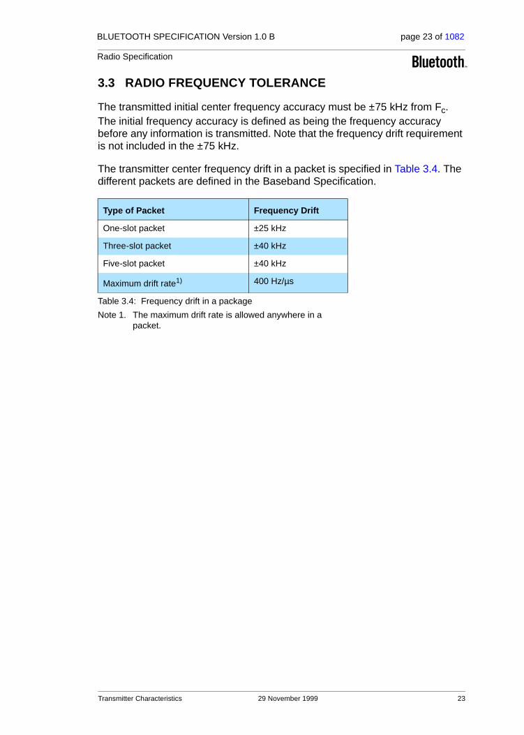
3.3 RADIO FREQUENCY TOLERANCE
The transmitted initial center frequency accuracy must be ±75 kHz from Fc. The initial frequency accuracy is defined as being the frequency accuracy before any information is transmitted. Note that the frequency drift requirement is not included in the ±75 kHz.
The transmitter center frequency drift in a packet is specified in Table 3.4. The different packets are defined in the Baseband Specification.
Type of Packet Frequency Drift
One-slot packet ±25 kHz
Three-slot packet ±40 kHz
Five-slot packet ±40 kHz
Maximum drift rate1)
Note 1. The maximum drift rate is allowed anywhere in a packet.
400 Hz/µs
Table 3.4: Frequency drift in a package
Transmitter Characteristics 29 November 1999 23

BLUETOOTH SPECIFICATION Version 1.0 B page 24 of 1082
Radio Specification
4 RECEIVER CHARACTERISTICS
In order to measure the bit error rate performance; the equipment must have a “loop back” facility. The equipment sends back the decoded information. This facility is specified in the Test Mode Specification.
The reference sensitivity level referred to in this chapter equals -70 dBm.
4.1 ACTUAL SENSITIVITY LEVEL
The actual sensitivity level is defined as the input level for which a raw bit error rate (BER) of 0.1% is met. The requirement for a Bluetooth receiver is an actual sensitivity level of –70 dBm or better. The receiver must achieve the –70 dBm sensitivity level with any Bluetooth transmitter compliant to the transmitter specification specified in Section 3 on page 20.
4.2 INTERFERENCE PERFORMANCE
The interference performance on Co-channel and adjacent 1 MHz and 2 MHz are measured with the wanted signal 10 dB over the reference sensitivity level. On all other frequencies the wanted signal shall be 3 dB over the reference sensitivity level. Should the frequency of an interfering signal lie outside of the band 2400-2497 MHz, the out-of-band blocking specification (see Section 4.3 on page 25) shall apply. The interfering signal shall be Bluetooth-modulated (see section 4.8 on page 27). The BER shall be ≤ 0.1%. The signal to interference ratio shall be:
Requirement Ratio
Co-Channel interference, C/Ico-channel 11 dB1)
Note 1. These specifications are tentative and will be fixed within 18 months after the release of the Bluetooth specification version 1.0. Implementations have to fulfil the final specification after a 3-years’ convergence period starting at the release of the Bluetooth specification version 1.0. During the convergence period, devices need to achieve a co-channel interference resistance of +14 dB, an ACI (@1MHz) resistance of +4 dB, Image frequency interference resistance of –6 dB and an ACI to in-band image frequency resistance of –16 dB.
Adjacent (1 MHz) interference, C/I1MHz 0 dB1
Adjacent (2 MHz) interference, C/I2MHz -30 dB
Adjacent (≥3 MHz) interference, C/I≥3MHz -40 dB
Image frequency Interference2) 3), C/IImage
Note 2. In-band image frequency
Note 3. If the image frequency ≠ n*1 MHz, than the image reference frequency is defined as the closest n*1 MHz frequency.
Note 4. If two adjacent channel specifications from Table 4.1 are applicable to the same channel, the more relaxed specification applies.
-9 dB1
Adjacent (1 MHz) interference to in-band image frequency, C/IImage±1MHz
-20 dB1
Table 4.1: Interference performance
24 29 November 1999 Receiver Characteristics

BLUETOOTH SPECIFICATION Version 1.0 B page 25 of 1082
Radio Specification
These specifications are only to be tested at nominal temperature conditions with a receiver hopping on one frequency, meaning that the synthesizer must change frequency between receive slot and transmit slot, but always return to the same receive frequency.
Frequencies where the requirements are not met are called spurious response frequencies. Five spurious response frequencies are allowed at frequencies with a distance of ≥2 MHz from the wanted signal. On these spurious response frequencies a relaxed interference requirement C/I = -17 dB shall be met.
4.3 OUT-OF-BAND BLOCKING
The Out of band blocking is measured with the wanted signal 3 dB over the ref-erence sensitivity level. The interfering signal shall be a continuous wave sig-nal. The BER shall be ≤ 0.1%. The Out of band blocking shall fulfil the following requirements:
24 exceptions are permitted which are dependent upon the given receive chan-nel frequency and are centered at a frequency which is an integer multiple of 1 MHz. At 19 of these spurious response frequencies a relaxed power level -50 dBm of the interferer may used to achieve a BER of 0.1%. At the remaining 5 spurious response frequencies the power level is arbitrary.
4.4 INTERMODULATION CHARACTERISTICS
The reference sensitivity performance, BER = 0.1%, shall be met under the fol-lowing conditions.
• The wanted signal at frequency f0 with a power level 6 dB over the reference sensitivity level.
• A static sine wave signal at f1 with a power level of –39 dBm
• A Bluetooth modulated signal (see Section 4.8 on page 27) at f2 with a power level of -39 dBm
Such that f0=2f1-f2 and f2-f1 =n*1 MHz, where n can be 3, 4, or 5. The system must fulfil one of the three alternatives.
Interfering Signal Frequency
Interfering Signal Power Level
30 MHz - 2000 MHz -10 dBm
2000 - 2399 MHz -27 dBm
2498 – 3000 MHz -27 dBm
3000 MHz – 12.75 GHz -10 dBm
Table 4.2: Out of Band blocking requirements
Receiver Characteristics 29 November 1999 25

BLUETOOTH SPECIFICATION Version 1.0 B page 26 of 1082
Radio Specification
4.5 MAXIMUM USABLE LEVEL
The maximum usable input level the receiver shall operate at shall be better than –20 dBm. The BER shall be less or equal to 0,1% at –20* dBm input power.
4.6 SPURIOUS EMISSIONS
The spurious emission for a Bluetooth receiver shall not be more than:
The measured power should be measured in a 100 kHz bandwidth.
4.7 RECEIVER SIGNAL STRENGTH INDICATOR (OPTIONAL)
A transceiver that wishes to take part in a power-controlled link must be able to measure its own receiver signal strength and determine if the transmitter on the other side of the link should increase or decrease its output power level. A Receiver Signal Strength Indicator (RSSI) makes this possible.
The way the power control is specified is to have a golden receive power. This golden receive power is defined as a range with a low limit and a high limit. The RSSI must have a minimum dynamic range equal to this range. The RSSI must have an absolute accuracy of ±4dB or better when the receive signal power is –60 dBm. In addition, a minimum range of 20±6 dB must be covered, starting from –60 dB and up (see Figure 4.1 on page 26).
Figure 4.1: RSSI dynamic range and accuracy
Frequency Band Requirement
30 MHz - 1 GHz -57 dBm
1 GHz – 12.75 GHz -47 dBm
Table 4.3: Out-of-band spurious emission
High limit
Low limit
20±6dB
-60dBm±4
26 29 November 1999 Receiver Characteristics
BLUETOOTH SPECIFICATION Version 1.0 B page 27 of 1082
Radio Specification
4.8 REFERENCE INTERFERENCE-SIGNAL DEFINITION
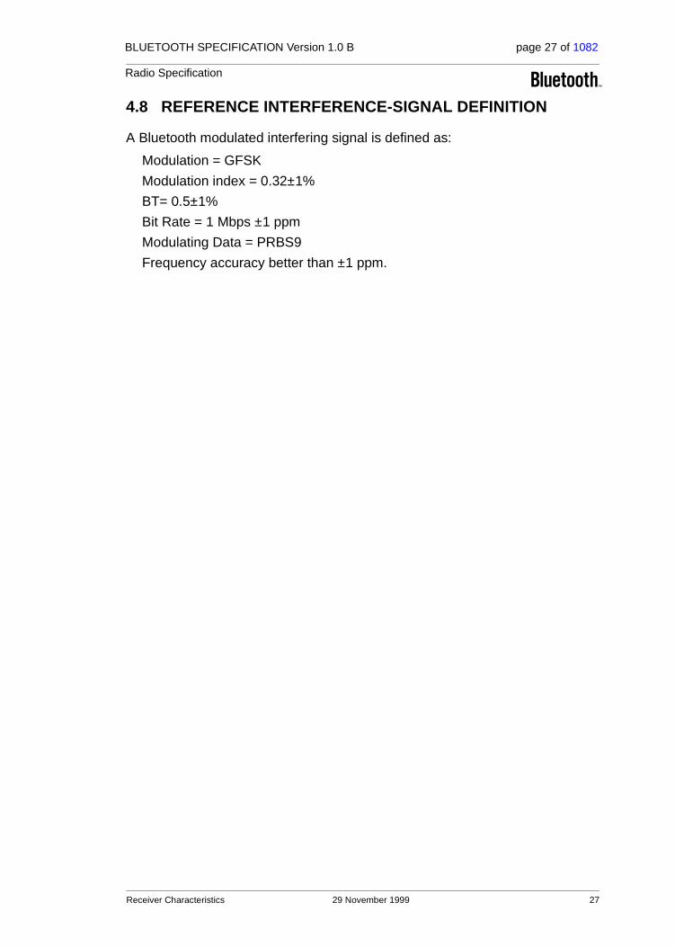
A Bluetooth modulated interfering signal is defined as:
Modulation = GFSK
Modulation index = 0.32±1%
BT= 0.5±1%
Bit Rate = 1 Mbps ±1 ppm
Modulating Data = PRBS9
Frequency accuracy better than ±1 ppm.
Receiver Characteristics 29 November 1999 27

BLUETOOTH SPECIFICATION Version 1.0 B page 28 of 1082
Radio Specification
5 APPENDIX A
5.1 NOMINAL TEST CONDITIONS (NTC)
5.1.1 Nominal temperature
The nominal temperature conditions for tests shall be +15 to +35 oC. When it is impractical to carry out the test under this condition a note to this effect, stating the ambient temperature, shall be recorded. The actual value during the test shall be recorded in the test report.
5.1.2 Nominal Power source
5.1.2.1 Mains Voltage
The nominal test voltage for equipment to be connected to the mains shall be the nominal mains voltage. The nominal voltage shall be declared voltage or any of the declared voltages for which the equipment was designed. The fre-quency of the test power source corresponding to the AC mains shall be within 2% of the nominal frequency.
5.1.2.2 Lead-acid battery power sources used in vehicles
When radio equipment is intended for operation from the alternator-fed lead-acid battery power sources which are standard in vehicles, then the nominal test voltage shall be 1.1 times the nominal voltage of the battery (6V, 12V, etc.).
5.1.2.3 Other power sources
For operation from other power sources or types of battery (primary or second-ary), the nominal test voltage shall be as declared by the equipment manufac-turer. This shall be recorded in the test report.
28 29 November 1999 Appendix A

BLUETOOTH SPECIFICATION Version 1.0 B page 29 of 1082
Radio Specification
5.2 EXTREME TEST CONDITIONS
5.2.1 Extreme temperatures
The extreme temperature range is defined as the largest temperature range given by the combination of:
• · The minimum temperature range 0 °C to +35 °C
• · The product operating temperature range declared by the manufacturer.
This extreme temperature range and the declared operating temperature range shall be recorded in the test report.
5.2.2 Extreme power source voltages
Tests at extreme power source voltages specified below are not required when the equipment under test is designed for operation as part of and powered by another system or piece of equipment. Where this is the case, the limit values of the host system or host equipment shall apply. The appropriate limit values shall be declared by the manufacturer and recorded in the test report.
5.2.2.1 Mains voltage
The extreme test voltage for equipment to be connected to an AC mains source shall be the nominal mains voltage ±10%.
5.2.2.2 Lead-acid battery power source used on vehicles
When radio equipment is intended for operation from the alternator-fed lead-acid battery power sources which are standard in vehicles, then extreme test voltage shall be 1.3 and 0.9 times the nominal voltage of the battery (6V, 12V etc.)
5.2.2.3 Power sources using other types of batteries
The lower extreme test voltage for equipment with power sources using the fol-lowing types of battery, shall be
a) for Leclanché, alkaline, or lithium type battery: 0.85 times the nominal voltage of the battery
b) for the mercury or nickel-cadmium types of battery: 0.9 times the nominal voltage of the battery.
In both cases, the upper extreme test voltage shall be 1.15 times the nominal voltage of the battery.
Appendix A 29 November 1999 29

BLUETOOTH SPECIFICATION Version 1.0 B page 30 of 1082
Radio Specification
5.2.2.4 Other power sources
For equipment using other power sources, or capable of being operated from a variety of power sources (primary or secondary), the extreme test voltages shall be those declared by the manufacturer. These shall be recorded in the test report.
30 29 November 1999 Appendix A

BLUETOOTH SPECIFICATION Version 1.0 B page 31 of 1082
Radio Specification
6 APPENDIX B
The Radio parameters shall be tested in the following conditions
ETC = Extreme Test ConditionsNTC = Nominal Test Conditions
Parameter Temperature Power source
Output Power ETC ETC
Power control NTC NTC
Modulation index ETC ETC
Initial Carrier Frequency accuracy ETC ETC
Carrier Frequency drift ETC ETC
In-band spurious emissions ETC ETC
Out-of-band Spurious Emissions ETC ETC
Sensitivity ETC ETC
Interference Performance NTC NTC
Intermodulation Characteristics NTC NTC
Out-of-band blocking NTC NTC
Maximum Usable Level NTC NTC
Receiver Signal Strength Indicator NTC NTC
Appendix B 29 November 1999 31

BLUETOOTH SPECIFICATION Version 1.0 B page 32 of 1082
Radio Specification
32 29 November 1999 Appendix B

Part B
BASEBAND SPECIFICATION
This document describes the specifications of the Bluetooth link controller which carries out the baseband protocols and other low-level link routines.

34 29 November 1999
BLUETOOTH SPECIFICATION Version 1.0 B page 34 of 1082
Baseband Specification

BLUETOOTH SPECIFICATION Version 1.0 B page 35 of 1082
Baseband Specification
CONTENTS
1 General Description ...........................................................................41
2 Physical Channel................................................................................432.1 Frequency Band and RF Channels............................................432.2 Channel Definition......................................................................432.3 Time Slots ..................................................................................432.4 Modulation and Bit Rate.............................................................44
3 Physical Links ....................................................................................453.1 General ......................................................................................453.2 SCO Link....................................................................................453.3 ACL Link ....................................................................................46
4 Packets................................................................................................474.1 General Format..........................................................................474.2 Access Code..............................................................................48
4.2.1 Access code types ........................................................48
4.2.2 Preamble .......................................................................49
4.2.3 Sync Word.....................................................................49
4.2.4 Trailer ............................................................................504.3 Packet Header ...........................................................................51
4.3.1 AM_ADDR.....................................................................51
4.3.2 TYPE.............................................................................51
4.3.3 FLOW............................................................................52
4.3.4 ARQN............................................................................52
4.3.5 SEQN ............................................................................52
4.3.6 HEC...............................................................................524.4 Packet Types .............................................................................54
4.4.1 Common packet types...................................................554.4.1.1 ID packet.........................................................554.4.1.2 NULL packet ...................................................554.4.1.3 POLL packet ...................................................554.4.1.4 FHS packet .....................................................564.4.1.5 DM1 packet.....................................................58
4.4.2 SCO packets .................................................................584.4.2.1 HV1 packet .....................................................584.4.2.2 HV2 packet .....................................................594.4.2.3 HV3 packet .....................................................594.4.2.4 DV packet .......................................................59
29 November 1999 35

BLUETOOTH SPECIFICATION Version 1.0 B page 36 of 1082
Baseband Specification
4.4.3 ACL packets..................................................................604.4.3.1 DM1 packet ....................................................604.4.3.2 DH1 packet .....................................................604.4.3.3 DM3 packet ....................................................604.4.3.4 DH3 packet .....................................................604.4.3.5 DM5 packet ....................................................614.4.3.6 DH5 packet .....................................................614.4.3.7 AUX1 packet...................................................61
4.5 Payload Format .........................................................................62
4.5.1 Voice field......................................................................62
4.5.2 Data field.......................................................................624.6 Packet Summary .......................................................................65
5 Error Correction .................................................................................675.1 FEC Code: Rate 1/3 ..................................................................675.2 FEC Code: Rate 2/3 ..................................................................675.3 ARQ Scheme.............................................................................68
5.3.1 Unnumbered ARQ.........................................................68
5.3.2 Retransmit filtering ........................................................70
5.3.3 Flushing payloads .........................................................71
5.3.4 Multi-slave considerations.............................................72
5.3.5 Broadcast packets ........................................................725.4 Error Checking...........................................................................73
6 Logical Channels ...............................................................................776.1 LC Channel (Link Control) .........................................................776.2 LM Channel (Link Manager) ......................................................776.3 UA/UI Channel (User Asynchronous/Isochronous data) ...........776.4 US Channel (User Synchronous data) ......................................786.5 Channel Mapping.......................................................................78
7 Data Whitening...................................................................................79
8 Transmit/Receive Routines ...............................................................818.1 TX Routine.................................................................................81
8.1.1 ACL traffic .....................................................................82
8.1.2 SCO traffic.....................................................................83
8.1.3 Mixed data/voice traffic .................................................83
8.1.4 Default packet types .....................................................848.2 RX Routine ................................................................................848.3 Flow Control...............................................................................85
8.3.1 Destination control ........................................................85
8.3.2 Source control ...............................................................858.4 Bitstream Processes..................................................................86
36 29 November 1999
BLUETOOTH SPECIFICATION Version 1.0 B page 37 of 1082
Baseband Specification
9 Transmit/Receive Timing...................................................................879.1 Master/Slave Timing Synchronization........................................879.2 Connection State .......................................................................889.3 Return From Hold Mode.............................................................909.4 Park Mode Wake-up ..................................................................909.5 Page State .................................................................................919.6 FHS Packet ................................................................................919.7 Multi-slave Operation .................................................................93
10 Channel Control .................................................................................9510.1 Scope.........................................................................................9510.2 Master-Slave Definition..............................................................9510.3 Bluetooth Clock..........................................................................9510.4 Overview of States.....................................................................9710.5 Standby State ............................................................................9810.6 Access Procedures ....................................................................99
10.6.1 General..........................................................................99
10.6.2 Page scan ....................................................................99
10.6.3 Page............................................................................101
10.6.4 Page response procedures .........................................10410.6.4.1 Slave response .............................................10510.6.4.2 Master response ...........................................107
10.7 Inquiry Procedures...................................................................108
10.7.1 General........................................................................108
10.7.2 Inquiry scan.................................................................109
10.7.3 Inquiry..........................................................................110
10.7.4 Inquiry response.......................................................... 11110.8 Connection State .....................................................................112
10.8.1 Active mode.................................................................113
10.8.2 Sniff mode ...................................................................114
10.8.3 Hold mode...................................................................114
10.8.4 Park mode...................................................................11510.8.4.1 Beacon channel ............................................11510.8.4.2 Beacon access window ................................11710.8.4.3 Parked slave synchronization .......................11910.8.4.4 Parking..........................................................12010.8.4.5 Master-activated unparking...........................12010.8.4.6 Slave-activated unparking ............................12010.8.4.7 Broadcast scan window ................................121
10.8.5 Polling schemes ..........................................................12110.8.5.1 Polling in active mode...................................12110.8.5.2 Polling in park mode .....................................122
29 November 1999 37

BLUETOOTH SPECIFICATION Version 1.0 B page 38 of 1082
Baseband Specification
10.8.6 Slot reservation scheme..............................................122
10.8.7 Broadcast scheme ......................................................12210.9 Scatternet ................................................................................122
10.9.1 General .......................................................................122
10.9.2 Inter-piconet communications .....................................123
10.9.3 Master-slave switch.....................................................12310.10 Power Management.................................................................125
10.10.1 Packet handling ..........................................................125
10.10.2 Slot occupancy............................................................125
10.10.3 Low-power modes.......................................................12510.11 Link Supervision ......................................................................126
11 Hop Selection ...................................................................................12711.1 General Selection Scheme ......................................................12711.2 Selection Kernel.......................................................................129
11.2.1 First addition operation................................................130
11.2.2 XOR operation ............................................................130
11.2.3 Permutation operation.................................................131
11.2.4 Second addition operation ..........................................133
11.2.5 Register bank..............................................................13311.3 Control Word............................................................................133
11.3.1 Page scan and Inquiry scan substates .......................135
11.3.2 Page substate .............................................................135
11.3.3 Page response............................................................13611.3.3.1 Slave response.............................................13611.3.3.2 Master response...........................................136
11.3.4 Inquiry substate...........................................................137
11.3.5 Inquiry response .........................................................137
11.3.6 Connection state .........................................................138
12 Bluetooth Audio ...............................................................................13912.1 LOG PCM CODEC ..................................................................13912.2 CVSD CODEC.........................................................................13912.3 Error Handling..........................................................................14212.4 General Audio Requirements ..................................................142
12.4.1 Signal levels................................................................142
12.4.2 CVSD audio quality .....................................................142
38 29 November 1999

BLUETOOTH SPECIFICATION Version 1.0 B page 39 of 1082
Baseband Specification
13 Bluetooth Addressing......................................................................14313.1 Bluetooth Device Address (BD_ADDR) ...................................14313.2 Access Codes ..........................................................................143
13.2.1 Synchronization word definition...................................144
13.2.2 Pseudo-random noise sequence generation...............146
13.2.3 Reserved addresses for GIAC and DIAC....................14713.3 Active Member Address (AM_ADDR)......................................14713.4 Parked Member Address (PM_ADDR) ....................................14813.5 Access Request Address (AR_ADDR) ....................................148
14 Bluetooth Security ...........................................................................14914.1 Random Number Generation ...................................................15014.2 Key Management .....................................................................150
14.2.1 Key types.....................................................................151
14.2.2 Key generation and initialization..................................15314.2.2.1 Generation of initialization key, ....................15314.2.2.2 Authentication ...............................................15414.2.2.3 Generation of a unit key................................15414.2.2.4 Generation of a combination key ..................15514.2.2.5 Generating the encryption key......................15614.2.2.6 Point-to-multipoint configuration ...................15714.2.2.7 Modifying the link keys..................................15714.2.2.8 Generating a master key ..............................158
14.3 Encryption ................................................................................159
14.3.1 Encryption key size negotiation...................................160
14.3.2 Encryption modes........................................................161
14.3.3 Encryption concept......................................................161
14.3.4 Encryption algorithm....................................................16314.3.4.1 The operation of the cipher...........................165
14.3.5 LFSR initialization........................................................165
14.3.6 Key stream sequence..................................................16814.4 Authentication ..........................................................................169
14.4.1 Repeated attempts......................................................17014.5 The Authentication And Key-Generating Functions.................171
14.5.1 The authentication function E1....................................171
14.5.2 The functions Ar and A’r ..............................................17314.5.2.1 The round computations ...............................17314.5.2.2 The substitution boxes “e” and “l” .................17414.5.2.3 Key scheduling .............................................175
14.5.3 E2-Key generation function for authentication ............175
14.5.4 E3-Key generation function for encryption ..................177
15 List of Figures...................................................................................179
16 List of Tables ....................................................................................183
29 November 1999 39

BLUETOOTH SPECIFICATION Version 1.0 B page 40 of 1082
Baseband Specification
40 29 November 1999

BLUETOOTH SPECIFICATION Version 1.0 B page 41 of 1082
Baseband Specification
1 GENERAL DESCRIPTION
Bluetooth is a short-range radio link intended to replace the cable(s) connect-ing portable and/or fixed electronic devices. Key features are robustness, low complexity, low power, and low cost.
Bluetooth operates in the unlicensed ISM band at 2.4 GHz. A frequency hop transceiver is applied to combat interference and fading. A shaped, binary FM modulation is applied to minimize transceiver complexity. The symbol rate is 1 Ms/s. A slotted channel is applied with a nominal slot length of 625 µs. For full duplex transmission, a Time-Division Duplex (TDD) scheme is used. On the channel, information is exchanged through packets. Each packet is transmitted on a different hop frequency. A packet nominally covers a single slot, but can be extended to cover up to five slots.
The Bluetooth protocol uses a combination of circuit and packet switching. Slots can be reserved for synchronous packets. Bluetooth can support an asynchronous data channel, up to three simultaneous synchronous voice channels, or a channel which simultaneously supports asynchronous data and synchronous voice. Each voice channel supports a 64 kb/s synchronous (voice) channel in each direction. The asynchronous channel can support max-imal 723.2 kb/s asymmetric (and still up to 57.6 kb/s in the return direction), or 433.9 kb/s symmetric.
The Bluetooth system consists of a radio unit (see Radio Specification), a link control unit, and a support unit for link management and host terminal interface functions, see Figure 1.1 on page 41. The current document describes the specifications of the Bluetooth link controller, which carries out the baseband protocols and other low-level link routines. Link layer messages for link set-up and control are defined in the Link Manager Protocol on page 185.
Figure 1.1: Different functional blocks in the Bluetooth system
The Bluetooth system provides a point-to-point connection (only two Bluetooth units involved), or a point-to-multipoint connection, see Figure 1.2 on page 42. In the point-to-multipoint connection, the channel is shared among several Bluetooth units. Two or more units sharing the same channel form a piconet. One Bluetooth unit acts as the master of the piconet, whereas the other unit(s)
host2.4 GHz
Bluetoothradio
Bluetoothlink
controller
Bluetoothlink
manager & I/O
General Description 29 November 1999 41

BLUETOOTH SPECIFICATION Version 1.0 B page 42 of 1082
Baseband Specification
acts as slave(s). Up to seven slaves can be active in the piconet. In addition, many more slaves can remain locked to the master in a so-called parked state. These parked slaves cannot be active on the channel, but remain synchro-nized to the master. Both for active and parked slaves, the channel access is controlled by the master.
Multiple piconets with overlapping coverage areas form a scatternet. Each piconet can only have a single master. However, slaves can participate in dif-ferent piconets on a time-division multiplex basis. In addition, a master in one piconet can be a slave in another piconet. The piconets shall not be time- or frequency-synchronized. Each piconet has its own hopping channel.
Figure 1.2: Piconets with a single slave operation (a), a multi-slave operation (b) and a scatternet operation (c).
a b c
Master
Slave
42 29 November 1999 General Description

BLUETOOTH SPECIFICATION Version 1.0 B page 43 of 1082
Baseband Specification
2 PHYSICAL CHANNEL
2.1 FREQUENCY BAND AND RF CHANNELS
Bluetooth operates in the 2.4 GHz ISM band. Although globally available, the exact location and the width of the band may differ by country. In the US and Europe, a band of 83.5 MHz width is available; in this band, 79 RF channels spaced 1 MHz apart are defined. In Japan, Spain, and France, a smaller band is available; in this band, 23 RF channels spaced 1 MHz apart are defined.
2.2 CHANNEL DEFINITION
The channel is represented by a pseudo-random hopping sequence hopping through the 79 or 23 RF channels. The hopping sequence is unique for the piconet and is determined by the Bluetooth device address of the master; the phase in the hopping sequence is determined by the Bluetooth clock of the master. The channel is divided into time slots where each slot corresponds to an RF hop frequency. Consecutive hops correspond to different RF hop fre-quencies. The nominal hop rate is 1600 hops/s. All Bluetooth units participating in the piconet are time- and hop-synchronized to the channel.
2.3 TIME SLOTS
The channel is divided into time slots, each 625 µs in length. The time slots are numbered according to the Bluetooth clock of the piconet master. The slot numbering ranges from 0 to 227-1 and is cyclic with a cycle length of 227.
In the time slots, master and slave can transmit packets.
A TDD scheme is used where master and slave alternatively transmit, see Figure 2.1 on page 44. The master shall start its transmission in even-numbered time slots only, and the slave shall start its transmission in odd-numbered time slots only. The packet start shall be aligned with the slot start. Packets transmitted by the master or the slave may extend over up to five time slots.
Country Frequency Range RF Channels
Europe* & USA
*. except Spain and France
2400 - 2483.5 MHz f = 2402 + k MHz k= 0,...,78
Japan 2471 - 2497 MHz f = 2473 + k MHz k= 0,...,22
Spain 2445 - 2475 MHz f = 2449 + k MHz k= 0,...,22
France 2446.5 - 2483.5 MHz f = 2454 + k MHz k= 0,...,22
Table 2.1: Available RF channels
Physical Channel 29 November 1999 43
BLUETOOTH SPECIFICATION Version 1.0 B page 44 of 1082
Baseband Specification
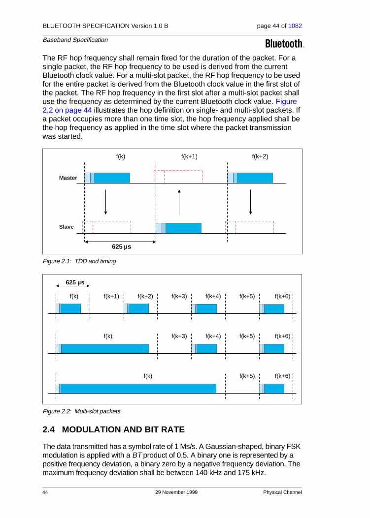
The RF hop frequency shall remain fixed for the duration of the packet. For a single packet, the RF hop frequency to be used is derived from the current Bluetooth clock value. For a multi-slot packet, the RF hop frequency to be used for the entire packet is derived from the Bluetooth clock value in the first slot of the packet. The RF hop frequency in the first slot after a multi-slot packet shall use the frequency as determined by the current Bluetooth clock value. Figure 2.2 on page 44 illustrates the hop definition on single- and multi-slot packets. If a packet occupies more than one time slot, the hop frequency applied shall be the hop frequency as applied in the time slot where the packet transmission was started.
Figure 2.1: TDD and timing
Figure 2.2: Multi-slot packets
2.4 MODULATION AND BIT RATE
The data transmitted has a symbol rate of 1 Ms/s. A Gaussian-shaped, binary FSK modulation is applied with a BT product of 0.5. A binary one is represented by a positive frequency deviation, a binary zero by a negative frequency deviation. The maximum frequency deviation shall be between 140 kHz and 175 kHz.
f(k) f(k+1) f(k+2)
625 µs
Master
Slave
f(k)
625 µs
f(k+1) f(k+2) f(k+3) f(k+4) f(k+5)
f(k) f(k+3) f(k+4) f(k+5)
f(k) f(k+5)
f(k+6)
f(k+6)
f(k+6)
44 29 November 1999 Physical Channel
BLUETOOTH SPECIFICATION Version 1.0 B page 45 of 1082
Baseband Specification
3 PHYSICAL LINKS
3.1 GENERAL
Between master and slave(s), different types of links can be established. Two link types have been defined:
• Synchronous Connection-Oriented (SCO) link
• Asynchronous Connection-Less (ACL) link
The SCO link is a point-to-point link between a master and a single slave in the piconet. The master maintains the SCO link by using reserved slots at regular intervals. The ACL link is a point-to-multipoint link between the master and all the slaves participating on the piconet. In the slots not reserved for the SCO link(s), the master can establish an ACL link on a per-slot basis to any slave, including the slave(s) already engaged in an SCO link.
3.2 SCO LINK
The SCO link is a symmetric, point-to-point link between the master and a spe-cific slave. The SCO link reserves slots and can therefore be considered as a circuit-switched connection between the master and the slave. The SCO link typically supports time-bounded information like voice. The master can support up to three SCO links to the same slave or to different slaves. A slave can sup-port up to three SCO links from the same master, or two SCO links if the links originate from different masters. SCO packets are never retransmitted.
The master will send SCO packets at regular intervals, the so-called SCO inter-val TSCO (counted in slots) to the slave in the reserved master-to-slave slots. The SCO slave is always allowed to respond with an SCO packet in the follow-ing slave-to-master slot unless a different slave was addressed in the previous master-to-slave slot. If the SCO slave fails to decode the slave address in the packet header, it is still allowed to return an SCO packet in the reserved SCO slot.
The SCO link is established by the master sending an SCO setup message via the LM protocol. This message will contain timing parameters such as the SCO interval TSCO and the offset DSCO to specify the reserved slots.
In order to prevent clock wrap-around problems, an initialization flag in the LMP setup message indicates whether initialization procedure 1 or 2 is being used. The slave shall apply the initialization method as indicated by the initialization flag. The master uses initialization 1 when the MSB of the current master clock (CLK27) is 0; it uses initialization 2 when the MSB of the current master clock (CLK27) is 1. The master-to-slave SCO slots reserved by the master and the slave shall be initialized on the slots for which the clock satisfies the following equation:
Physical Links 29 November 1999 45

BLUETOOTH SPECIFICATION Version 1.0 B page 46 of 1082
Baseband Specification
CLK27-1 mod TSCO = DSCO for initialization 1
(CLK27,CLK26-1) mod TSCO = DSCO for initialization 2
The slave-to-master SCO slots shall directly follow the reserved master-to-slave SCO slots. After initialization, the clock value CLK(k+1) for the next mas-ter-to-slave SCO slot is found by adding the fixed interval TSCO to the clock value of the current master-to-slave SCO slot:
CLK(k+1) = CLK(k) + TSCO
3.3 ACL LINK
In the slots not reserved for SCO links, the master can exchange packets with any slave on a per-slot basis. The ACL link provides a packet-switched con-nection between the master and all active slaves participating in the piconet. Both asynchronous and isochronous services are supported. Between a mas-ter and a slave only a single ACL link can exist. For most ACL packets, packet retransmission is applied to assure data integrity.
A slave is permitted to return an ACL packet in the slave-to-master slot if and only if it has been addressed in the preceding master-to-slave slot. If the slave fails to decode the slave address in the packet header, it is not allowed to transmit.
ACL packets not addressed to a specific slave are considered as broadcast packets and are read by every slave. If there is no data to be sent on the ACL link and no polling is required, no transmission shall take place.
46 29 November 1999 Physical Links

BLUETOOTH SPECIFICATION Version 1.0 B page 47 of 1082
Baseband Specification
4 PACKETS
4.1 GENERAL FORMAT
The bit ordering when defining packets and messages in the Baseband Specification, follows the Little Endian format, i.e., the following rules apply:
• The least significant bit (LSB) corresponds to ;
• The LSB is the first bit sent over the air;
• In illustrations, the LSB is shown on the left side;
The baseband controller interprets the first bit arriving from a higher software layer as ; i.e. this is the first bit to be sent over the air. Furthermore, data fields generated internally at baseband level, such as the packet header fields and payload header length, are transmitted with the LSB first. For instance, a 3-bit parameter X=3 is sent as over the air where 1 is sent first
and 0 is sent last.
The data on the piconet channel is conveyed in packets. The general packet format is shown in Figure 4.1 on page 47. Each packet consists of 3 entities: the access code, the header, and the payload. In the figure, the number of bits per entity is indicated.
Figure 4.1: Standard packet format.
The access code and header are of fixed size: 72 bits and 54 bits respectively. The payload can range from zero to a maximum of 2745 bits. Different packet types have been defined. Packets may consist of the (shortened) access code only (see ID packet on page 55), of the access code − header, or of the access code − header − payload.
b0
b0
b0b1b2 110=
ACCESS CODE
HEADER
54 0 - 274572
PAYLOAD
LSB MSB
Packets 29 November 1999 47

BLUETOOTH SPECIFICATION Version 1.0 B page 48 of 1082
Baseband Specification
4.2 ACCESS CODE
Each packet starts with an access code. If a packet header follows, the access code is 72 bits long, otherwise the access code is 68 bits long. This access code is used for synchronization, DC offset compensation and identification. The access code identifies all packets exchanged on the channel of the pico-net: all packets sent in the same piconet are preceded by the same channel access code. In the receiver of the Bluetooth unit, a sliding correlator correlates against the access code and triggers when a threshold is exceeded. This trig-ger signal is used to determine the receive timing.
The access code is also used in paging and inquiry procedures. In this case, the access code itself is used as a signalling message and neither a header nor a payload is present.
The access code consists of a preamble, a sync word, and possibly a trailer, see Figure 4.2 on page 48. For details see Section 4.2.1 on page 48.
Figure 4.2: Access code format
4.2.1 Access code types
There are three different types of access codes defined:
• Channel Access Code (CAC)
• Device Access Code (DAC)
• Inquiry Access Code (IAC)
The respective access code types are used for a Bluetooth unit in different operating modes. The channel access code identifies a piconet. This code is included in all packets exchanged on the piconet channel. The device access code is used for special signalling procedures, e.g., paging and response to paging. For the inquiry access code there are two variations. A general inquiry access code (GIAC) is common to all devices. The GIAC can be used to dis-cover which other Bluetooth units are in range. The dedicated inquiry access code (DIAC) is common for a dedicated group of Bluetooth units that share a common characteristic. The DIAC can be used to discover only these dedi-cated Bluetooth units in range.
The CAC consists of a preamble, sync word, and trailer and its total length is 72 bits. When used as self-contained messages without a header, the DAC and IAC do not include the trailer bits and are of length 68 bits.
PREAMBLE
644
SYNC WORD
LSB
TRAILER
4 MSB
48 29 November 1999 Packets

BLUETOOTH SPECIFICATION Version 1.0 B page 49 of 1082
Baseband Specification
The different access code types use different Lower Address Parts (LAPs) to construct the sync word. The LAP field of the BD address is explained in Sec-tion 13.1 on page 143. A summary of the different access code types can be found in Table 4.1 on page 49.
4.2.2 Preamble
The preamble is a fixed zero-one pattern of 4 symbols used to facilitate DC compensation. The sequence is either 1010 or 0101, depending whether the LSB of the following sync word is 1 or 0, respectively. The preamble is shown in Figure 4.3 on page 49.
Figure 4.3: Preamble
4.2.3 Sync Word
The sync word is a 64-bit code word derived from a 24 bit address (LAP); for the CAC the master’s LAP is used; for the GIAC and the DIAC, reserved, dedi-cated LAPs are used; for the DAC, the slave unit LAP is used. The construction guarantees large Hamming distance between sync words based on different LAPs. In addition, the good autocorrelation properties of the sync word improve on the timing synchronization process. The derivation of the sync word is described in Section 13.2 on page 143
Code type LAP Code length Comments
CAC Master 72
See also Section 13.2 on page 143
DAC Paged unit 68/72*
*. length 72 is only used in combination with FHS packets
GIAC Reserved 68/72*
DIAC Dedicated 68/72*
Table 4.1: Summary of access code types.
preamble sync word
0 1 0 1 0
LSB LSB LSBMSB LSB MSB
preamble sync word
1 0 1 0 1
Packets 29 November 1999 49

BLUETOOTH SPECIFICATION Version 1.0 B page 50 of 1082
Baseband Specification
4.2.4 Trailer
The trailer is appended to the sync word as soon as the packet header follows the access code. This is typically the case with the CAC, but the trailer is also used in the DAC and IAC when these codes are used in FHS packets exchanged during page response and inquiry response procedures.
The trailer is a fixed zero-one pattern of four symbols. The trailer together with the three MSBs of the syncword form a 7-bit pattern of alternating ones and zeroes which may be used for extended DC compensation. The trailer sequence is either 1010 or 0101 depending on whether the MSB of the sync word is 0 or 1, respectively. The choice of trailer is illustrated in Figure 4.4 on page 50.
Figure 4.4: Trailer in CAC when MSB of sync word is 0 (a), and when MSB of sync word is 1 (b).
sync word trailer
b)a)
0 1 0 1- - - - 1
MSB MSBLSB MSB LSB MSB
sync word trailer
1 0 1 0- - - - 0
50 29 November 1999 Packets

BLUETOOTH SPECIFICATION Version 1.0 B page 51 of 1082
Baseband Specification
4.3 PACKET HEADER
The header contains link control (LC) information and consists of 6 fields:
• AM_ADDR: 3- bit active member address
• TYPE: 4-bit type code
• FLOW: 1-bit flow control
• ARQN: 1-bit acknowledge indication
• SEQN: 1-bit sequence number
• HEC: 8-bit header error check
The total header, including the HEC, consists of 18 bits, see Figure 4.5 on page 51, and is encoded with a rate 1/3 FEC (not shown but described in Section 5.1 on page 67) resulting in a 54-bit header. Note that the AM_ADDR and TYPE fields are sent with their LSB first. The function of the different fields will be explained next.
Figure 4.5: Header format.
4.3.1 AM_ADDR
The AM_ADDR represents a member address and is used to distinguish between the active members participating on the piconet. In a piconet, one or more slaves are connected to a single master. To identify each slave sepa-rately, each slave is assigned a temporary 3-bit address to be used when it is active. Packets exchanged between the master and the slave all carry the AM_ADDR of this slave; that is, the AM_ADDR of the slave is used in both master-to-slave packets and in the slave-to-master packets. The all-zero address is reserved for broadcasting packets from the master to the slaves. An exception is the FHS packet which may use the all-zero member address but is not a broadcast message (Section 4.4.1.4 on page 56). Slaves that are disconnected or parked give up their AM_ADDR. A new AM_ADDR has to be assigned when they re-enter the piconet.
4.3.2 TYPE
Sixteen different types of packets can be distinguished. The 4-bit TYPE code specifies which packet type is used. Important to note is that the interpretation of the TYPE code depends on the physical link type associated with the packet. First, it shall be determined whether the packet is sent on an SCO link or an ACL link. Then it can be determined which type of SCO packet or ACL packet has been received. The TYPE code also reveals how many slots the current packet will occupy. This allows the non-addressed receivers to refrain
4
TYPE
1
SEQN
8
HEC
3
AM_ADDR
1
FLOW
1
ARQN
MSBLSB
Packets 29 November 1999 51
BLUETOOTH SPECIFICATION Version 1.0 B page 52 of 1082
Baseband Specification
from listening to the channel for the duration of the remaining slots. In Section 4.4 on page 54, each packet type will be described in more detail.
4.3.3 FLOW
This bit is used for flow control of packets over the ACL link. When the RX buffer for the ACL link in the recipient is full and is not emptied, a STOP indica-tion (FLOW=0) is returned to stop the transmission of data temporarily. Note, that the STOP signal only concerns ACL packets. Packets including only link control information (ID, POLL and NULL packets) or SCO packets can still be received. When the RX buffer is empty, a GO indication (FLOW=1) is returned. When no packet is received, or the received header is in error, a GO is assumed implicitly.
4.3.4 ARQN
The 1-bit acknowledgment indication ARQN is used to inform the source of a successful transfer of payload data with CRC, and can be positive acknowl-edge ACK or negative acknowledge NAK. If the reception was successful, an ACK (ARQN=1) is returned, otherwise a NAK (ARQN=0) is returned. When no return message regarding acknowledge is received, a NAK is assumed implic-itly. NAK is also the default return information.
The ARQN is piggy-backed in the header of the return packet. The success of the reception is checked by means of a cyclic redundancy check (CRC) code. An unnumbered ARQ scheme which means that the ARQN relates to the latest received packet from the same source, is used. See Section 5.3 on page 68 for initialization and usage of this bit.
4.3.5 SEQN
The SEQN bit provides a sequential numbering scheme to order the data packet stream. For each new transmitted packet that contains data with CRC, the SEQN bit is inverted. This is required to filter out retransmissions at the destination; if a retransmission occurs due to a failing ACK, the destination receives the same packet twice. By comparing the SEQN of consecutive pack-ets, correctly received retransmissions can be discarded. The SEQN has to be added due to a lack of packet numbering in the unnumbered ARQ scheme. See section 5.3.2 on page 70 for initialization and usage of the SEQN bit. For broadcast packets, a modified sequencing method is used, see Section 5.3.5 on page 72.
4.3.6 HEC
Each header has a header-error-check to check the header integrity. The HEC consists of an 8-bit word generated by the polynomial 647 (octal representa-tion). Before generating the HEC, the HEC generator is initialized with an 8-bit value. For FHS packets sent in master page response state, the slave upper
52 29 November 1999 Packets
BLUETOOTH SPECIFICATION Version 1.0 B page 53 of 1082
Baseband Specification
address part (UAP) is used. For FHS packets sent in inquiry response, the default check initialization (DCI, see Section 5.4) is used. In all other cases, the UAP of the master device is used. For the definition of Bluetooth device addresses, see Section 13.1 on page 143.
After the initialization, a HEC is calculated for the 10 header bits. Before check-ing the HEC, the receiver must initialize the HEC check circuitry with the proper 8-bit UAP (or DCI). If the HEC does not check, the entire packet is disregarded. More information can be found in Section 5.4 on page 73.
Packets 29 November 1999 53
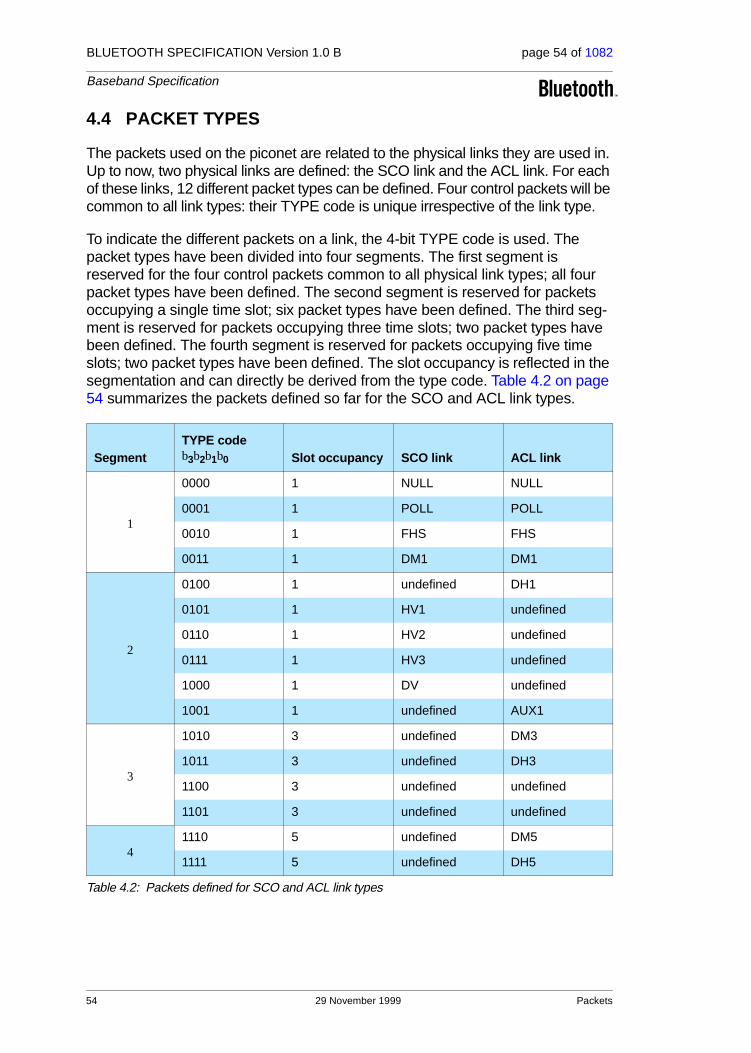
BLUETOOTH SPECIFICATION Version 1.0 B page 54 of 1082
Baseband Specification
4.4 PACKET TYPES
The packets used on the piconet are related to the physical links they are used in. Up to now, two physical links are defined: the SCO link and the ACL link. For each of these links, 12 different packet types can be defined. Four control packets will be common to all link types: their TYPE code is unique irrespective of the link type.
To indicate the different packets on a link, the 4-bit TYPE code is used. The packet types have been divided into four segments. The first segment is reserved for the four control packets common to all physical link types; all four packet types have been defined. The second segment is reserved for packets occupying a single time slot; six packet types have been defined. The third seg-ment is reserved for packets occupying three time slots; two packet types have been defined. The fourth segment is reserved for packets occupying five time slots; two packet types have been defined. The slot occupancy is reflected in the segmentation and can directly be derived from the type code. Table 4.2 on page 54 summarizes the packets defined so far for the SCO and ACL link types.
SegmentTYPE codeb3b2b1b0 Slot occupancy SCO link ACL link
1
0000 1 NULL NULL
0001 1 POLL POLL
0010 1 FHS FHS
0011 1 DM1 DM1
2
0100 1 undefined DH1
0101 1 HV1 undefined
0110 1 HV2 undefined
0111 1 HV3 undefined
1000 1 DV undefined
1001 1 undefined AUX1
3
1010 3 undefined DM3
1011 3 undefined DH3
1100 3 undefined undefined
1101 3 undefined undefined
41110 5 undefined DM5
1111 5 undefined DH5
Table 4.2: Packets defined for SCO and ACL link types
54 29 November 1999 Packets

BLUETOOTH SPECIFICATION Version 1.0 B page 55 of 1082
Baseband Specification
4.4.1 Common packet types
There are five common packets. In addition to the types listed in segment 1 of the previous table, there is the ID packet not listed. Each packet will now be examined in more detail.
4.4.1.1 ID packet
The identity or ID packet consists of the device access code (DAC) or inquiry access code (IAC). It has a fixed length of 68 bits. It is a very robust packet since the receiver uses a bit correlator to match the received packet to the known bit sequence of the ID packet. The packet is used, for example, in pag-ing, inquiry, and response routines.
4.4.1.2 NULL packet
The NULL packet has no payload and therefore consists of the channel access code and packet header only. Its total (fixed) length is 126 bits. The NULL packet is used to return link information to the source regarding the success of the previous transmission (ARQN), or the status of the RX buffer (FLOW). The NULL packet itself does not have to be acknowledged.
4.4.1.3 POLL packet
The POLL packet is very similar to the NULL packet. It does not have a pay-load either. In contrast to the NULL packet, it requires a confirmation from the recipient. It is not a part of the ARQ scheme. The POLL packet does not affect the ARQN and SEQN fields. Upon reception of a POLL packet the slave must respond with a packet. This return packet is an implicit acknowledgement of the POLL packet. This packet can be used by the master in a piconet to poll the slaves, which must then respond even if they do not have information to send.
Packets 29 November 1999 55

BLUETOOTH SPECIFICATION Version 1.0 B page 56 of 1082
Baseband Specification
4.4.1.4 FHS packet
The FHS packet is a special control packet revealing, among other things, the Bluetooth device address and the clock of the sender. The payload contains 144 information bits plus a 16-bit CRC code. The payload is coded with a rate 2/3 FEC which brings the gross payload length to 240 bits. The FHS packet covers a single time slot.
Figure 4.6 on page 56 illustrates the format and contents of the FHS payload. The payload consists of eleven fields. The FHS packet is used in page master response, inquiry response and in master slave switch. In page master response or master slave switch, it is retransmitted until its reception is acknowledged or a timeout has exceeded. In inquiry response, the FHS packet is not acknowledged. The FHS packet contains real-time clock information. This clock information is updated before each retransmission. The retransmis-sion of the FHS payload is thus somewhat different from the retransmission of ordinary data payloads where the same payload is used for each retransmis-sion. The FHS packet is used for frequency hop synchronization before the piconet channel has been established, or when an existing piconet changes to a new piconet. In the former case, the recipient has not been assigned an active member address yet, in which case the AM_ADDR field in the FHS packet header is set to all-zeroes; however, the FHS packet should not be considered as a broadcast packet. In the latter case the slave already has an AM_ADDR in the existing piconet, which is then used in the FHS packet header.
Figure 4.6: Format of the FHS payload
Each field is described in more detail below:
Parity bitsThis 34-bit field contains the parity bits that form the first part of the sync word of the access code of the unit that sends the FHS packet. These bits are derived from the LAP as described in section 13.2 on page 143.
LAPThis 24-bit field contains the lower address part of the unit that sends the FHS packet.
Undefined This 2-bit field is reserved for future use and shall be set to zero.
SRThis 2-bit field is the scan repetition field and indicates the interval between two consecutive page scan windows, see also Table 4.4 and Table 10.1 on page 101
Table 4.3: Description of the FHS payload
Parity bits LAPUn-
definedSR SP UAP NAP
LSB MSB
Class of device
AM_ADDR
CLK27-2
Page scan mode
34 24 2 2 2 8 16 24 3 26 3
56 29 November 1999 Packets

BLUETOOTH SPECIFICATION Version 1.0 B page 57 of 1082
Baseband Specification
SPThis 2-bit field is the scan period field and indicates the period in which the mandatory page scan mode is applied after transmission of an inquiry response message, see also Table 4.5 and Table 10.6 on page 112.
UAPThis 8-bit field contains the upper address part of the unit that sends the FHS packet.
NAPThis 16-bit field contains the non-significant address part of the unit that sends the FHS packet (see also section 13.1 on page 143 for LAP, UAP, and NAP).
Class of device
This 24-bit field contains the class of device of the unit that sends the FHS packet. The class of device has not been defined yet.
AM_ADDR
This 3-bit field contains the member address the recipient shall use if the FHS packet is used at call setup or master-slave switch. A slave responding to a master or a unit responding to an inquiry request message shall include an all-zero AM_ADDR field if it sends the FHS packet.
CLK27-2
This 26-bit field contains the value of the native system clock of the unit that sends the FHS packet, sampled at the beginning of the transmission of the access code of this FHS packet. This clock value has a resolution of 1.25ms (two-slot interval). For each new transmission, this field is updated so that it accurately reflects the real-time clock value.
Page scan mode
This 3-bit field indicates which scan mode is used by default by the sender of the FHS packet. The interpretation of the page scan mode is illustrated in Table 4.6. Currently, the standard supports one mandatory scan mode and up to three optional scan modes (see also “Appendix VII” on page 999).
SR bit format b1b0 SR mode
00 R0
01 R1
10 R2
11 reserved
Table 4.4: Contents of SR field
SP bit format b1b0 SP mode
00 P0
01 P1
10 P2
11 reserved
Table 4.5: Contents of SP field
Table 4.3: Description of the FHS payload
Packets 29 November 1999 57

BLUETOOTH SPECIFICATION Version 1.0 B page 58 of 1082
Baseband Specification
The LAP, UAP, and NAP together form the 48-bit IEEE address of the unit that sends the FHS packet. Using the parity bits and the LAP, the recipient can directly construct the channel access code of the sender of the FHS packet.
4.4.1.5 DM1 packet
DM1 serves as part of segment 1 in order to support control messages in any link type. However, it can also carry regular user data. Since the DM1 packet is recognized on the SCO link, it can interrupt the synchronous information to send control information. Since the DM1 packet can be regarded as an ACL packet, it will be discussed in Section 4.4.3 on page 60.
4.4.2 SCO packets
SCO packets are used on the synchronous SCO link. The packets do not include a CRC and are never retransmitted. SCO packets are routed to the synchronous I/O (voice) port. Up to now, three pure SCO packets have been defined. In addition, an SCO packet is defined which carries an asynchronous data field in addition to a synchronous (voice) field. The SCO packets defined so far are typically used for 64 kb/s speech transmission.
4.4.2.1 HV1 packet
The HV1 packet carries 10 information bytes. The bytes are protected with a rate 1/3 FEC. No CRC is present. The payload length is fixed at 240 bits. There is no payload header present.
HV packets are typically used for voice transmission. HV stands for High-quality Voice. The voice packets are never retransmitted and need no CRC.
Bit format b2b1b0 Page scan mode
000 Mandatory scan mode
001 Optional scan mode I
010 Optional scan mode II
011 Optional scan mode III
100 Reserved for future use
101 Reserved for future use
110 Reserved for future use
111 Reserved for future use
Table 4.6: Contents of page scan mode field
58 29 November 1999 Packets

BLUETOOTH SPECIFICATION Version 1.0 B page 59 of 1082
Baseband Specification
An HV1 packet can carry 1.25ms of speech at a 64 kb/s rate. In that case, an HV1 packet has to be sent every two time slots (TSCO=2).
4.4.2.2 HV2 packet
The HV2 packet carries 20 information bytes. The bytes are protected with a rate 2/3 FEC. No CRC is present. The payload length is fixed at 240 bits. There is no payload header present.
If the HV2 packet is used for voice at a 64 kb/s rate, it can carry 2.5ms of speech. In that case, an HV2 packet has to be sent every four time slots (TSCO=4).
4.4.2.3 HV3 packet
The HV3 packet carries 30 information bytes. The bytes are not protected by FEC. No CRC is present. The payload length is fixed at 240 bits. There is no payload header present.
If the HV3 packet is used for voice at a 64 kb/s rate, it can carry 3.75ms of speech. In that case, an HV3 packet has to be sent every six time slots (TSCO=6).
4.4.2.4 DV packet
The DV packet is a combined data - voice packet. The payload is divided into a voice field of 80 bits and a data field containing up to 150 bits, see Figure 4.7. The voice field is not protected by FEC. The data field contains up to 10 infor-mation bytes (including the 1-byte payload header) and includes a 16-bit CRC. The data field is encoded with a rate 2/3 FEC. If necessary, extra zeroes are appended to assure that the total number of payload bits is a multiple of 10 prior to FEC encoding. Since the DV packet has to be sent at regular intervals due to its synchronous (voice) contents, it is listed under the SCO packet types. The voice and data fields are treated completely separate. The voice field is handled like normal SCO data and is never retransmitted; that is, the voice field is always new. The data field is checked for errors and is retransmit-ted if necessary.
Figure 4.7: DV packet format
ACCESS CODE
VOICE FIELD
HEADER
54 80 32 - 15072
DATAFIELD
LSB MSB
Packets 29 November 1999 59

BLUETOOTH SPECIFICATION Version 1.0 B page 60 of 1082
Baseband Specification
4.4.3 ACL packets
ACL packets are used on the asynchronous links. The information carried can be user data or control data. Including the DM1 packet, seven ACL packets have been defined. Six of the ACL packets contain a CRC code and retrans-mission is applied if no acknowledgement of proper reception is received (except in case a flush operation is carried out, see Section 5.3.3 on page 71). The 7th ACL packet, the AUX1 packet, has no CRC and is not retransmitted.
4.4.3.1 DM1 packet
The DM1 packet is a packet that carries data information only. DM stands for Data − Medium rate. The payload contains up to 18 information bytes (includ-ing the 1-byte payload header) plus a 16-bit CRC code. The DM1 packet may cover up to a single time slot. The information plus CRC bits are coded with a rate 2/3 FEC which adds 5 parity bits to every 10-bit segment. If necessary, extra zeros are appended after the CRC bits to get the total number of bits (information bits, CRC bits, and tail bits) equal a multiple of 10. The payload header in the DM1 packet is only 1 byte long, see Figure 4.8 on page 62. The length indicator in the payload header specifies the number of user bytes (excluding payload header and the CRC code).
4.4.3.2 DH1 packet
This packet is similar to the DM1 packet, except that the information in the pay-load is not FEC encoded. As a result, the DH1 packet can carry up to 28 infor-mation bytes plus a 16-bit CRC code. DH stands for Data − High rate. The DH1 packet may cover up to a single time slot.
4.4.3.3 DM3 packet
The DM3 packet is a DM1 packet with an extended payload. The DM3 packet may cover up to three time slots. The payload contains up to 123 information bytes (including the 2-bytes payload header) plus a 16-bit CRC code. The pay-load header in the DM3 packet is 2 bytes long, see Figure 4.9 on page 62. The length indicator in the payload header specifies the number of user bytes (excluding payload header and the CRC code). When a DM3 packet is sent or received, the RF hop frequency shall not change for a duration of three time slots (the first time slot being the slot where the channel access code was transmitted).
4.4.3.4 DH3 packet
This packet is similar to the DM3 packet, except that the information in the pay-load is not FEC encoded. As a result, the DH3 packet can carry up to 185 infor-mation bytes (including the two bytes payload header) plus a 16-bit CRC code.
60 29 November 1999 Packets

BLUETOOTH SPECIFICATION Version 1.0 B page 61 of 1082
Baseband Specification
The DH3 packet may cover three time slots. When a DH3 packet is sent or received, the hop frequency shall not change for a duration of three time slots (the first time slot being the slot where the channel access code was transmit-ted).
4.4.3.5 DM5 packet
The DM5 packet is a DM1 packet with an extended payload. The DM5 packet may cover up to five time slots. The payload contains up to 226 information bytes (including the 2-bytes payload header) plus a 16-bit CRC code. The pay-load header in the DM5 packet is 2 bytes long. The length indicator in the pay-load header specifies the number of user bytes (excluding payload header and the CRC code). When a DM5 packet is sent or received, the hop frequency shall not change for a duration of five time slots (the first time slot being the slot where the channel access code was transmitted).
4.4.3.6 DH5 packet
This packet is similar to the DM5 packet, except that the information in the pay-load is not FEC encoded. As a result, the DH5 packet can carry up to 341 infor-mation bytes (including the two bytes payload header) plus a 16-bit CRC code. The DH5 packet may cover five time slots. When a DH5 packet is sent or received, the hop frequency shall not change for a duration of five time slots (the first time slot being the slot where the channel access code was transmit-ted).
4.4.3.7 AUX1 packet
This packet resembles a DH1 packet but has no CRC code. The AUX1 packet can carry up to 30 information bytes (including the 1-byte payload header). The AUX1 packet may cover up to a single time slot.
Packets 29 November 1999 61

BLUETOOTH SPECIFICATION Version 1.0 B page 62 of 1082
Baseband Specification
4.5 PAYLOAD FORMAT
In the previous packet overview, several payload formats were considered. In the payload, two fields are distinguished: the (synchronous) voice field and the (asynchronous) data field. The ACL packets only have the data field and the SCO packets only have the voice field − with the exception of the DV packets which have both.
4.5.1 Voice field
The voice field has a fixed length. For the HV packets, the voice field length is 240 bits; for the DV packet the voice field length is 80 bits. No payload header is present.
4.5.2 Data field
The data field consists of three segments: a payload header, a payload body, and possibly a CRC code (only the AUX1 packet does not carry a CRC code).
1. Payload header
Only data fields have a payload header. The payload header is one or two bytes long. Packets in segments one and two have a 1-byte payload header; packets in segments three and four have a 2-bytes payload header. The payload header specifies the logical channel (2-bit L_CH indication), con-trols the flow on the logical channels (1-bit FLOW indication), and has a pay-load length indicator (5 bits and 9 bits for 1-byte and 2-bytes payload header, respectively). In the case of a 2-byte payload header, the length indicator is extended by four bits into the next byte. The remaining four bits of the second byte are reserved for future use and shall be set to zero. The formats of the 1-byte and 2-bytes payload headers are shown in Figure 4.8 on page 62 and Figure 4.9 on page 62.
Figure 4.8: Payload header format for single-slot packets.
Figure 4.9: Payload header format for multi-slot packets.
The L_CH field is transmitted first, the length field last. In Table 4.7 on page 63, more details about the contents of the L_CH field are listed.
L_CH FLOW
1LSB
2
LENGTH
5MSB
L_CH FLOW
1
LENGTH UN-DEFINED
LSB MSB9 42
62 29 November 1999 Packets

BLUETOOTH SPECIFICATION Version 1.0 B page 63 of 1082
Baseband Specification
An L2CAP message can be fragmented into several packets. Code 10 is used for an L2CAP packet carrying the first fragment of such a message; code 01 is used for continuing fragments. If there is no fragmentation, code 10 is used for every packet. Code 11 is used for LMP messages. Code 00 is reserved for future use.
The flow indicator in the payload is used to control the flow at the L2CAP level. It is used to control the flow per logical channel (when applicable). FLOW=1 means flow-on (“OK to send") and FLOW=0 means flow-off ("stop"). There are no strict real-time requirements on the flow bit in the pay-load header. Flow bit in the last correctly received payload header deter-mines flow status. The link manager is responsible for setting and processing the flow bit in the payload header. Real-time flow control is car-ried out at the packet level by the link controller via the flow bit in the packet header (see Section 4.3.3 on page 52). With the payload flow bit, traffic from the remote end can be controlled. It is allowed to generate and send an ACL packet with payload load length zero. L2CAP start- and continue-fragment indications (L_CH=10 and L_CH=01) also retain their meaning when the payload length is equal to zero (i.e. an empty start-fragment should not be sent in the middle of an on-going L2CAP packet transmission). It is always safe to send an ACL packet with payload length=0 and L_CH=10. The pay-load flow bit has its own meaning for each logical channel (UA/I or LM), see Table 4.8 on page 63. On the LM channel, no flow control is applied and the payload flow bit is always set at one.
The length indicator indicates the number of bytes (i.e. 8-bit words) in the payload excluding the payload header and the CRC code; i.e. the payload body only. With reference to Figure 4.8 and Figure 4.9, the MSB of the length field in a 1-byte header is the last (right-most) bit in the payload
L_CH code b1b0
Logical Channel Information
00 NA undefined
01 UA/UI Continuation fragment of an L2CAP message
10 UA/UI Start of an L2CAP message or no fragmentation
11 LM LMP message
Table 4.7: Logical channel L_CH field contents
L_CH codeb1b0 Usage and semantics of the ACL payload header FLOW bit
00 Not defined, reserved for future use.
01 or 10 Flow control of the UA/I channels (which are used to send L2CAP messages)
11 Always set FLOW=1 on transmission and ignore the bit on reception
Table 4.8: Use of payload header flow bit on the logical channels.
Packets 29 November 1999 63

BLUETOOTH SPECIFICATION Version 1.0 B page 64 of 1082
Baseband Specification
header; the MSB of the length field in a 2-byte header is the fourth bit (from left) of the second byte in the payload header.
2. Payload body
The payload body includes the user host information and determines the effective user throughput. The length of the payload body is indicated in the length field of the payload header.
3. CRC code generation
The 16-bit cyclic redundancy check code in the payload is generated by the CRC-CCITT polynomial 210041 (octal representation). It is generated in a way similar to the HEC. Before determining the CRC code, an 8-bit value is used to initialize the CRC generator. For the CRC code in the FHS packets sent in master page response state, the UAP of the slave is used. For the FHS packet sent in inquiry response state, the DCI (see Section 5.4) is used. For all other packets, the UAP of the master is used.
The 8 bits are loaded into the 8 least significant (left-most) positions of the LFSR circuit, see Figure 5.10 on page 76. The other 8 bits are at the same time reset to zero. Subsequently, the CRC code is calculated over the infor-mation. Then the CRC code is appended to the information; the UAP (or DCI) is disregarded. At the receive side, the CRC circuitry is in the same way initialized with the 8-bit UAP (DCI) before the received information is checked. More information can be found in Section 5.4 on page 73.
64 29 November 1999 Packets

BLUETOOTH SPECIFICATION Version 1.0 B page 65 of 1082
Baseband Specification
4.6 PACKET SUMMARY
A summary of the packets and their characteristics is shown in Table 4.9, Table 4.10 and Table 4.11. The user payload represents the packet payload excluding FEC, CRC, and payload header.
TypeUser Payload (bytes) FEC CRC
Symmetric Max. Rate
Asymmetric Max. Rate
ID na na na na na
NULL na na na na na
POLL na na na na na
FHS 18 2/3 yes na na
Table 4.9: Link control packets
Type
Payload Header(bytes)
UserPayload (bytes) FEC CRC
SymmetricMax. Rate (kb/s)
Asymmetric Max. Rate (kb/s)
Forward Reverse
DM1 1 0-17 2/3 yes 108.8 108.8 108.8
DH1 1 0-27 no yes 172.8 172.8 172.8
DM3 2 0-121 2/3 yes 258.1 387.2 54.4
DH3 2 0-183 no yes 390.4 585.6 86.4
DM5 2 0-224 2/3 yes 286.7 477.8 36.3
DH5 2 0-339 no yes 433.9 723.2 57.6
AUX1 1 0-29 no no 185.6 185.6 185.6
Table 4.10: ACL packets
TypePayload Header (bytes)
User Payload (bytes) FEC CRC
Symmetric Max. Rate (kb/s)
HV1 na 10 1/3 no 64.0
HV2 na 20 2/3 no 64.0
HV3 na 30 no no 64.0
DV*
*. Items followed by ‘D’ relate to data field only.
1 D 10+(0-9) D 2/3 D yes D 64.0+57.6 D
Table 4.11: SCO packets
Packets 29 November 1999 65

BLUETOOTH SPECIFICATION Version 1.0 B page 66 of 1082
Baseband Specification
66 29 November 1999 Packets

BLUETOOTH SPECIFICATION Version 1.0 B page 67 of 1082
Baseband Specification
5 ERROR CORRECTION
There are three error correction schemes defined for Bluetooth:
• 1/3 rate FEC
• 2/3 rate FEC
• ARQ scheme for the data
The purpose of the FEC scheme on the data payload is to reduce the number of retransmissions. However, in a reasonable error-free environment, FEC gives unnecessary overhead that reduces the throughput. Therefore, the packet definitions given in Section 4 have been kept flexible to use FEC in the payload or not, resulting in the DM and DH packets for the ACL link and the HV packets for the SCO link. The packet header is always protected by a 1/3 rate FEC; it contains valuable link information and should be able to sustain more bit errors.
Correction measures to mask errors in the voice decoder are not included in this section. This matter is discussed in section Section 12.3 on page 142.
5.1 FEC CODE: RATE 1/3
A simple 3-times repetition FEC code is used for the header. The repetition code is implemented by repeating the bit three times, see the illustration in Fig-ure 5.1 on page 67. The 3-bit repetition code is used for the entire header, and also for the voice field in the HV1 packet.
Figure 5.1: Bit-repetition encoding scheme.
5.2 FEC CODE: RATE 2/3
The other FEC scheme is a (15,10) shortened Hamming code. The generator polynomial is . This corresponds to 65 in octal nota-tion. The LFSR generating this code is depicted in Figure 5.2 on page 68. Ini-tially all register elements are set to zero. The 10 information bits are sequentially fed into the LFSR with the switches S1 and S2 set in position 1. Then, after the final input bit, the switches S1 and S2 are set in position 2, and the five parity bits are shifted out. The parity bits are appended to the informa-tion bits. Consequently, each block of 10 information bits is encoded into a 15 bit codeword. This code can correct all single errors and detect all double errors in each codeword. This 2/3 rate FEC is used in the DM packets, in the data field of the DV packet, in the FHS packet, and in the HV2 packet. Since the encoder operates with information segments of length 10, tail bits with
b0
b0
b0
b1
b1
b1
b2
b2
b2
g D( ) D 1+( ) D4 D 1+ +( )=
Error Correction 29 November 1999 67
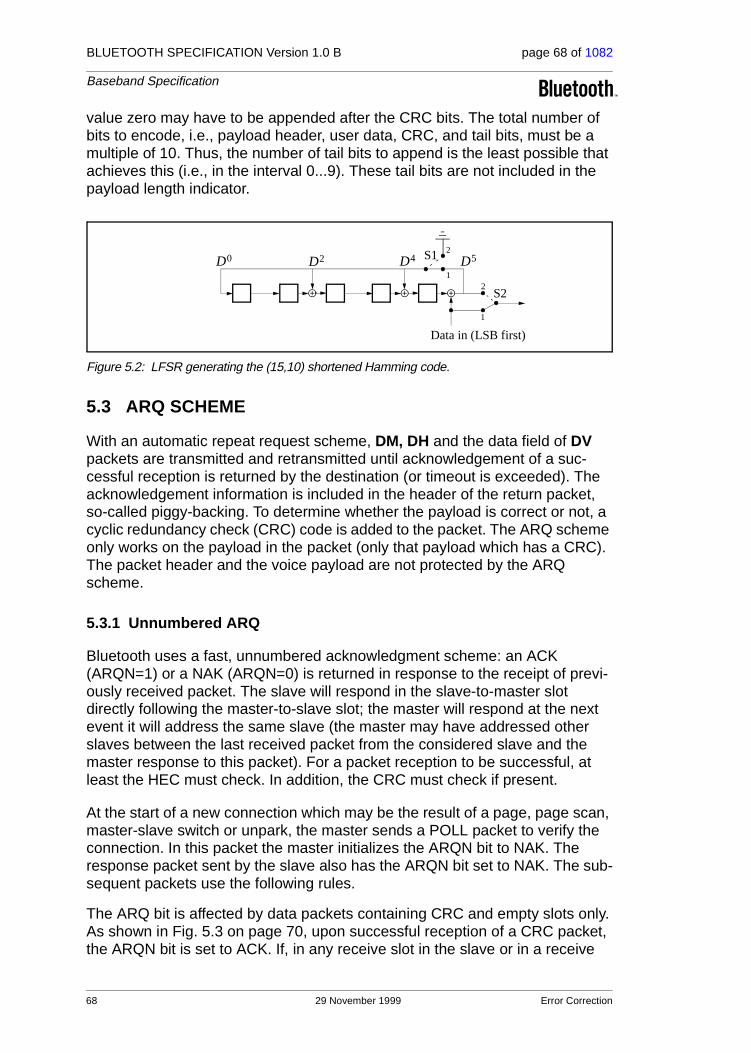
BLUETOOTH SPECIFICATION Version 1.0 B page 68 of 1082
Baseband Specification
value zero may have to be appended after the CRC bits. The total number of bits to encode, i.e., payload header, user data, CRC, and tail bits, must be a multiple of 10. Thus, the number of tail bits to append is the least possible that achieves this (i.e., in the interval 0...9). These tail bits are not included in the payload length indicator.
Figure 5.2: LFSR generating the (15,10) shortened Hamming code.
5.3 ARQ SCHEME
With an automatic repeat request scheme, DM, DH and the data field of DV packets are transmitted and retransmitted until acknowledgement of a suc-cessful reception is returned by the destination (or timeout is exceeded). The acknowledgement information is included in the header of the return packet, so-called piggy-backing. To determine whether the payload is correct or not, a cyclic redundancy check (CRC) code is added to the packet. The ARQ scheme only works on the payload in the packet (only that payload which has a CRC). The packet header and the voice payload are not protected by the ARQ scheme.
5.3.1 Unnumbered ARQ
Bluetooth uses a fast, unnumbered acknowledgment scheme: an ACK (ARQN=1) or a NAK (ARQN=0) is returned in response to the receipt of previ-ously received packet. The slave will respond in the slave-to-master slot directly following the master-to-slave slot; the master will respond at the next event it will address the same slave (the master may have addressed other slaves between the last received packet from the considered slave and the master response to this packet). For a packet reception to be successful, at least the HEC must check. In addition, the CRC must check if present.
At the start of a new connection which may be the result of a page, page scan, master-slave switch or unpark, the master sends a POLL packet to verify the connection. In this packet the master initializes the ARQN bit to NAK. The response packet sent by the slave also has the ARQN bit set to NAK. The sub-sequent packets use the following rules.
The ARQ bit is affected by data packets containing CRC and empty slots only. As shown in Fig. 5.3 on page 70, upon successful reception of a CRC packet, the ARQN bit is set to ACK. If, in any receive slot in the slave or in a receive
Data in (LSB first)
D5D4D2D0 S1
1
2
S2
1
2
68 29 November 1999 Error Correction
BLUETOOTH SPECIFICATION Version 1.0 B page 69 of 1082
Baseband Specification
slot following transmission of a packet in the master, no access code is detected, and the HEC check or the CRC check of a CRC packet fails, then the ARQN bit is set to NAK. Packets that have correct HEC but that are addressed to other slaves, or packets other than DH, DM, or DV packets, do not affect the ARQN bit. In these cases the ARQN bit is left as it was prior to reception of the packet. If a CRC packet with a correct header has the same SEQN as the pre-viously received CRC packet, the ARQN bit is set to ACK and the payload is disregarded without checking the CRC.
The ARQ bit in the FHS packet is not meaningful. Contents of the ARQN bit in the FHS packet should not be checked.
Broadcast packets are checked on errors using the CRC, but no ARQ scheme is applied. Broadcast packets are never acknowledged.
Inactive connection modes HOLD and SNIFF do not affect the ARQN scheme. After return from these modes, packets will continue using values from before the start of hold/sniff modes.
Error Correction 29 November 1999 69

BLUETOOTH SPECIFICATION Version 1.0 B page 70 of 1082
Baseband Specification
Figure 5.3: Receive protocol for determining the ARQN bit.
5.3.2 Retransmit filtering
The data payload is retransmitted until a positive acknowledgment is received (or a timeout is exceeded). A retransmission is carried out either because the packet transmission itself failed, or because the piggy-backed acknowledg-ment transmitted in the return packet failed (note that the latter has a lower fail-ure probability since the header is more heavily coded). In the latter case, the destination keeps receiving the same payload over and over again. In order to filter out the retransmissions in the destination, the SEQN bit is added in the header. Normally, this bit is alternated for every new CRC data payload trans-mission. In case of a retransmission, this bit is not changed. So the destination can compare the SEQN bit with the previous SEQN value. If different, a new data payload has arrived; otherwise it is the same data payload and can be dis-carded. Only new data payloads are transferred to the link manager. Note that CRC data payloads can be carried only by DM, DH or DV packets.
TRIGGER?
HEC OK?
AM_ADDR OK?
DM/DH/DV?
CRC OK?
ARQN=ACK innext transmission
ARQN=NAK innext transmission
Take previous ARQN in
next transmission
TX
F
F
F
F
F
RX
F
Reject payloadAccept payloadAccept payload Ignore payload
SEQN=SEQNOLD
SEQN = SEQNOLD
70 29 November 1999 Error Correction

BLUETOOTH SPECIFICATION Version 1.0 B page 71 of 1082
Baseband Specification
At the start of a new connection which may be the result of a page, page scan, master slave switch or unpark, the master sends a POLL packet to verify the connection. The slave responds with a packet. The SEQN bit of the first CRC data packet, on both the master and the slave sides, is set to 1. The subse-quent packets use the rules given below.
The SEQN bit is affected only by the CRC data packets as shown in Figure 5.4. It is inverted every time a new CRC data packet is sent. The CRC data packet is retransmitted with the same SEQN number until an ACK is received or the packet is flushed. When an ACK is received, the SEQN bit is inverted and a new payload is sent. When the packet is flushed (see Section 5.3.3 on page 71), a new payload is sent. The SEQN bit is not necessarily inverted. However, if an ACK is received before the new packet is sent, the SEQN bit is inverted. This procedure prevents loss of the first packet of a message (after the flush command has been given) due to the retransmit filtering.
Figure 5.4: Retransmit filtering for packets with CRC.
The SEQN bit in the FHS packet is not meaningful. This bit can be set to any value. Contents of the SEQN bit in the FHS packet should not be checked. During transmission of all other packets the SEQN bit remains the same as it was in the previous packet.
Inactive connection modes HOLD and SNIFF do not affect the SEQN scheme. After return from these modes, packets will continue using values from before the start of hold/sniff modes.
5.3.3 Flushing payloads
The ARQ scheme can cause variable delay in the traffic flow since retransmis-sions are inserted to assure error-free data transfer. For certain communication
DM/DH/DV?
Has latest DM/DH/DVpacket been
ACKed once?
Invert SEQN
TX
RX
F
F
Send new payload
FLUSH?
Send old payload
F
Error Correction 29 November 1999 71

BLUETOOTH SPECIFICATION Version 1.0 B page 72 of 1082
Baseband Specification
links, only a limited amount of delay is allowed: retransmissions are allowed up to a certain limit at which the current payload must be disregarded and the next payload must be considered. This data transfer is indicated as isochronous traffic. This means that the retransmit process must be overruled in order to continue with the next data payload. Aborting the retransmit scheme is accom-plished by flushing the old data and forcing the Bluetooth controller to take the next data instead.
Flushing results in loss of remaining portions of an L2CAP message. There-fore, the packet following the flush will have a start packet indication of L_CH = 10 in the payload header for the next L2CAP message. This informs the desti-nation of the flush. (see Section 4.5). Flushing will not necessarily result in a change in the SEQN bit value, see the previous section.
5.3.4 Multi-slave considerations
In case of a piconet with multiple slaves, the master carries out the ARQ proto-col independently to each slave.
5.3.5 Broadcast packets
Broadcast packets are packets transmitted by the master to all the slaves simultaneously. A broadcast packet is indicated by the all-zero AM_ADDR (note; the FHS packet is the only packet which may have an all-zero address but is not a broadcast packet). Broadcast packets are not acknowledged (at least not at the LC level).
Since broadcast messages are not acknowledged, each broadcast packet is repeated for a fixed number of times. A broadcast packet is repeated NBC times before the next broadcast packet of the same broadcast message is repeated, see Figure 5.5 on page 73.
Broadcast packets with a CRC have their own sequence number. The SEQN of the first broadcast packet with a CRC is set to SEQN = 1 by the master and it is inverted for each new broadcast packet with CRC thereafter. Broadcast pack-ets without a CRC have no influence on the sequence number. The slave accepts the SEQN of the first broadcast packet it receives in a connection and checks for change in SEQN for consequent broadcast packets. Since there is no acknowledgement of broadcast messages and there is no end packet indi-cation, it is important to receive the start packets correctly. To ensure this, rep-etitions of the broadcast packets that are L2CAP start packets and LMP packets will not be filtered out. These packets are indicated by L_CH=1X in the payload header as explained in section 4.5 on page 62. Only repetitions of the L2CAP continuation packets will be filtered out.
72 29 November 1999 Error Correction

BLUETOOTH SPECIFICATION Version 1.0 B page 73 of 1082
Baseband Specification
Figure 5.5: Broadcast repetition scheme
5.4 ERROR CHECKING
We can check the packet for errors or wrong delivery using the channel access code, the HEC in the header, and the CRC in the payload. At packet reception, first the access code is checked. Since the 64-bit sync word in the channel access code is derived from the 24-bit master LAP, this checks if the LAP is correct, and prevents the receiver from accepting a packet of another piconet.
The HEC and CRC are used to check both on errors and on a wrong address: to increase the address space with 8 bits, the UAP is normally included in the HEC and CRC checks. Then, even when a packet with the same access code − i.e., an access code of a device owning the same LAP but different UAP −passes the access code test, it will be discarded after the HEC and CRC tests when the UAP bits do not match. However, there is an exception where no common UAP is available in the transmitter and receiver. This is the case when the HEC and CRC are generated for the FHS packet in inquiry response state. In this case the default check initialization (DCI) value is used. The DCI is defined to be 0x00 (hexadecimal).
The generation and check of the HEC and CRC are summarized in Figure 5.8 on page 75 and Figure 5.11 on page 76. Before calculating the HEC or CRC, the shift registers in the HEC/CRC generators are initialized with the 8-bit UAP (or DCI) value. Then the header and payload information is shifted into the HEC and CRC generators, respectively (with the LSB first).
The HEC generating LFSR is depicted in Figure 5.6 on page 74. The generator polynomial is . Initially this circuit is pre-loaded with the 8-bit UAP such that the LSB of the UAP (denoted UAP0) goes to the left-most shift register element, and, UAP7 goes to the right-most element. The initial state of the HEC LFSR is depicted in Figure 5.7 on page 75. Then the data is shifted in with the switch S set in posi-tion 1. When the last data bit has been clocked into the LFSR, the switch S is set in position 2, and, the HEC can be read out from the register. The LFSR bits
NBC
t1 1 1 2 2 2 M
1 2 M
M M
1 2
broadcast message
broadcast packets
g D( ) D 1+( ) D7 D4 D3 D2 1+ + + +( ) D8 D7 D5 D2 D 1+ + + + += =
Error Correction 29 November 1999 73

BLUETOOTH SPECIFICATION Version 1.0 B page 74 of 1082
Baseband Specification
are read out from right to left (i.e., the bit in position 7 is the first to be transmit-ted, followed by the bit in position 6, etc.).
Figure 5.6: The LFSR circuit generating the HEC.
Data in (LSB first)
D8D7D5D2D0 D1 S
1
2
Position 0 1 2 3 4 65 7
74 29 November 1999 Error Correction
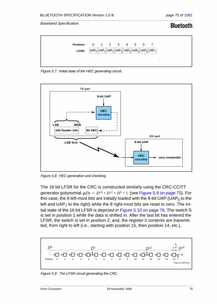
BLUETOOTH SPECIFICATION Version 1.0 B page 75 of 1082
Baseband Specification
Figure 5.7: Initial state of the HEC generating circuit.
Figure 5.8: HEC generation and checking.
The 16 bit LFSR for the CRC is constructed similarly using the CRC-CCITT generator polynomial (see Figure 5.9 on page 75). For this case, the 8 left-most bits are initially loaded with the 8-bit UAP (UAP0 to the left and UAP7 to the right) while the 8 right-most bits are reset to zero. The ini-tial state of the 16 bit LFSR is depicted in Figure 5.10 on page 76. The switch S is set in position 1 while the data is shifted in. After the last bit has entered the LFSR, the switch is set in position 2, and, the register ’s contents are transmit-ted, from right to left (i.e., starting with position 15, then position 14, etc.).
Figure 5.9: The LFSR circuit generating the CRC.
UAP0 UAP1 UAP2 UAP3 UAP4 UAP5 UAP6 UAP7
0 1 2 3 4 5 6 7Position:
LFSR:
zero remainder
8-bit UAP
circuitryHEC
8b HEC
LSB MSB
10b header info
RX part
TX part
circuitry
8-bit UAP
LSB first
HEC
g D( ) D16 D12 D5 1+ + +=
Data in (LSB first)
D16D12D5D0 S
1
2
Position 14 15131211109876543210
Error Correction 29 November 1999 75

BLUETOOTH SPECIFICATION Version 1.0 B page 76 of 1082
Baseband Specification
Figure 5.10: Initial state of the CRC generating circuit.
Figure 5.11: CRC generation and checking
UAP0 UAP1 UAP2 UAP3 UAP4 UAP5 UAP6 UAP7
0 1 2 3 4 5 6 7 8 9 10 11 12 13 14 15Position:
LFSR: 0 0 0 0 0 0 0 0
zero remainder
8-bit UAP appended with 8 zero bits
circuitryCRC
16b CRC
LSB MSB
data info
RX part
TX part
circuitry
8-bit UAP appended with 8 zero bits
LSB first
CRC
76 29 November 1999 Error Correction

BLUETOOTH SPECIFICATION Version 1.0 B page 77 of 1082
Baseband Specification
6 LOGICAL CHANNELS
In the Bluetooth system, five logical channels are defined:
• LC control channel
• LM control channel
• UA user channel
• UI user channel
• US user channel
The control channels LC and LM are used at the link control level and link man-ager level, respectively. The user channels UA, UI, and US are used to carry asynchronous, isochronous, and synchronous user information, respectively. The LC channel is carried in the packet header; all other channels are carried in the packet payload. The LM, UA, and UI channels are indicated in the L_CH field in the payload header. The US channel is carried by the SCO link only; the UA and UI channels are normally carried by the ACL link; however, they can also be carried by the data in the DV packet on the SCO link. The LM channel can be carried either by the SCO or the ACL link.
6.1 LC CHANNEL (Link Control)
The LC control channel is mapped onto the packet header. This channel car-ries low level link control information like ARQ, flow control, and payload char-acterization. The LC channel is carried in every packet except in the ID packet which has no packet header.
6.2 LM CHANNEL (Link Manager)
The LM control channel carries control information exchanged between the link managers of the master and the slave(s). Typically, the LM channel uses pro-tected DM packets. The LM channel is indicated by the L_CH code 11 in the payload header.
6.3 UA/UI CHANNEL (User Asynchronous/Isochronous Data)
The UA channel carries L2CAP transparent asynchronous user data. This data may be transmitted in one or more baseband packets. For fragmented mes-sages, the start packet uses an L_CH code of 10 in the payload header. Remaining continuation packets use L_CH code 01. If there is no fragmenta-tion, all packets use the L2CAP start code 10.
Isochronous data channel is supported by timing start packets properly at higher levels. At the baseband level, the L_CH code usage is the same as the UA channel.
Logical Channels 29 November 1999 77

BLUETOOTH SPECIFICATION Version 1.0 B page 78 of 1082
Baseband Specification
6.4 US CHANNEL (User Synchronous Data)
The US channel carries transparent synchronous user data. This channel is carried over the SCO link.
6.5 CHANNEL MAPPING
The LC channel is mapped onto the packet header. All other channels are mapped onto the payload. The US channel can only be mapped onto the SCO packets. All other channels are mapped on the ACL packets, or possibly the SCO DV packet. The LM, UA, and UI channels may interrupt the US channel if it concerns information of higher priority.
78 29 November 1999 Logical Channels

BLUETOOTH SPECIFICATION Version 1.0 B page 79 of 1082
Baseband Specification
7 DATA WHITENING
Before transmission, both the header and the payload are scrambled with a data whitening word in order to randomize the data from highly redundant pat-terns and to minimize DC bias in the packet. The scrambling is performed prior to the FEC encoding.
At the receiver, the received data is descrambled using the same whitening word generated in the recipient. The descrambling is performed after FEC decoding.
The whitening word is generated with the polynomial (i.e., 221 in octal representation) and is subsequently EXORed with the header and the payload. The whitening word is generated with the linear feedback shift register shown in Figure 7.1 on page 79. Before each transmission, the shift register is initialized with a portion of the master Bluetooth clock, CLK6-1, extended with an MSB of value one. This initialization is carried out with CLK1 written to position 0, CLK2 written to position 1, etc. An exception forms the FHS packet sent during frequency hop acquisition, where initialization of the whitening register is carried out differently. Instead of the master clock, the X-input used in the inquiry or page response (depending on current state) rou-tine is used, see Table 11.3 and Table 11.4 for the 79-hop and 23-hop systems, respectively. In case of a 79-hop system, the 5-bit values is extended with two MSBs of value one. In case of a 23-hop system, the 4-bit value is extended with three bits; the two MSBs are set to one and the third most significant bit is set to zero. During register initialization, the LSB of X (i.e., X0) is written to posi-tion 0, X1 is written to position 1, etc.
Figure 7.1: Data whitening LFSR.
After initialization, the packet header and the payload (including the CRC) are scrambled. The payload whitening continues from the state the whitening LFSR had at the end of HEC. There is no re-initialization of the shift register between packet header and payload. The first bit of the “Data In” sequence is the LSB of the packet header.
g D( ) D7 D4 1+ +=
data out
data in (LSB first)
D 0 D 4 D 7
0 1 2 3 4 5 6
Data Whitening 29 November 1999 79

BLUETOOTH SPECIFICATION Version 1.0 B page 80 of 1082
Baseband Specification
80 29 November 1999 Data Whitening

BLUETOOTH SPECIFICATION Version 1.0 B page 81 of 1082
Baseband Specification
8 TRANSMIT/RECEIVE ROUTINES
This section describes the way to use the packets as defined in Section 4 in order to support the traffic on the ACL and SCO links. Both single-slave and multi-slave configurations are considered. In addition, the use of buffers for the TX and RX routines are described.
The TX and RX routines described in sections 8.1 and 8.2 are of an informative character only. The final implementation may be carried out differently.
8.1 TX ROUTINE
The TX routine is carried out separately for each ACL link and each SCO link. Figure 8.1 on page 81 shows the ACL and SCO buffers as used in the TX rou-tine. In this figure, only a single TX ACL buffer and a single TX SCO buffer are shown. In the master, there is a separate TX ACL buffer for each slave. In addi-tion there may be one or more TX SCO buffers for each SCO slave (different SCO links may either reuse the same TX SCO buffer, or each have their own TX SCO buffer). Each TX buffer consists of two FIFO registers: one current register which can be accessed and read by the Bluetooth controller in order to compose the packets, and one next register that can be accessed by the Blue-tooth Link Manager to load new information. The positions of the switches S1 and S2 determine which register is current and which register is next; the switches are controlled by the Bluetooth Link Controller. The switches at the input and the output of the FIFO registers can never be connected to the same register simultaneously.
Figure 8.1: Functional diagram of TX buffering.
Of the packets common on the ACL and SCO links (ID, NULL, POLL, FHS, DM1) only the DM1 packet carries a payload that is exchanged between the Link Controller and the Link Manager; this common packet makes use of the
asynchronous I/O port
current/next data FIFO
next/current data FIFO
synchronous I/O port
current/next voice FIFO
next/current voice FIFO
packetcomposer
S1a S1b
S2bS2a
TX ACL buffer
TX SCO buffer
Transmit/Receive Routines 29 November 1999 81

BLUETOOTH SPECIFICATION Version 1.0 B page 82 of 1082
Baseband Specification
ACL buffer. All ACL packets make use of the ACL buffer. All SCO packets make use of the SCO buffer except for the DV packet where the voice part is handled by the SCO buffer and the data part is handled by the ACL buffer. In the next sections, the operation for ACL traffic, SCO traffic, and combined data-voice traffic on the SCO link will be considered.
8.1.1 ACL traffic
In the case of pure (asynchronous) data, only the TX ACL buffer in Figure 8.1 on page 81 has to be considered. In this case, only packet types DM or DH are used, and these can have different lengths. The length is indicated in the pay-load header. The selection of high-rate data or medium-rate data shall depend on the quality of the link. When the quality is good, the FEC in the data payload can be omitted, resulting in a DH packet. Otherwise, DM packets must be used.
The default TYPE in pure data traffic is NULL. This means that, if there is no data to be sent (the data traffic is asynchronous, and therefore pauses occur in which no data is available) or no slaves need to be polled, NULL packets are sent instead − in order to send link control information to the other Bluetooth unit (e.g. ACK/STOP information for received data). When no link control infor-mation is available either (no need to acknowledge and/or no need to stop the RX flow) no packet is sent at all.
The TX routine works as follows. The Bluetooth Link Manager loads new data information in the register to which the switch S1a points. Next, it gives a flush command to the Bluetooth Link Controller, which forces the switch S1 to change (both S1a and S1b switch in synchrony). When the payload needs to be sent, the packet composer reads the current register and, depending on the packet TYPE, builds a payload which is appended to the channel access code and the header and is subsequently transmitted. In the response packet (which arrives in the following RX slot if it concerned a master transmission, or may be postponed until some later RX slot if it concerned a slave transmission), the result of the transmission is reported back. In case of an ACK, the switch S1 changes position; if a NAK (explicit or implicit) is received instead, the switch S1 will not change position. In that case, the same payload is retransmitted at the next TX occasion.
As long as the Link Manager keeps loading the registers with new information, the Bluetooth Link Controller will automatically transmit the payload; in addi-tion, retransmissions are performed automatically in case of errors. The Link Controller will send NULL or nothing when no new data is loaded. If no new data has been loaded in the next register, during the last transmission, the packet composer will be pointing to an empty register after the last transmis-sion has been acknowledged and the next register becomes the current regis-ter. If new data is loaded in the next register, a flush command is required to switch the S1 switch to the proper register. As long as the Link Manager keeps loading the data and type registers before each TX slot, the data is automati-cally processed by the Link Controller since the S1 switch is controlled by the
82 29 November 1999 Transmit/Receive Routines
BLUETOOTH SPECIFICATION Version 1.0 B page 83 of 1082
Baseband Specification
ACK information received in response. However, if the traffic from the Link Manager is interrupted once and a default packet is sent instead, a flush com-mand is required to continue the flow in the Link Controller.
The flush command can also be used in case of time-bounded (isochronous) data. In case of a bad link, many retransmission are necessary. In certain appli-cations, the data is time-bounded: if a payload is retransmitted all the time because of link errors, it may become outdated, and the system might decide to continue with more recent data instead and skip the payload that does not come through. This is accomplished by the flush command as well. With the flush, the switch S1 is forced to change and the Link Controller is forced to consider the next data payload and overrules the ACK control.
8.1.2 SCO traffic
In case of an SCO link, we only use HV packet types. The synchronous port continuously loads the next register in the SCO buffer. The S2 switches are changed according to the Tsco interval. This Tsco interval is negotiated between the master and the slave at the time the SCO link is established.
For each new SCO slot, the packet composer reads the current register after which the S2 switch is changed. If the SCO slot has to be used to send control information with high priority concerning a control packet between the master and the considered SCO slave, or a control packet between the master and any other slave, the packet composer will discard the SCO information and use the control information instead. This control information must be sent in a DM1 packet. Data or link control information can also be exchanged between the master and the SCO slave by using the DV or DM1 packets. Any ACL type of packet can be used to sent data or link control information to any other ACL slave. This is discussed next.
8.1.3 Mixed data/voice traffic
In Section 4.4.2 on page 58, a DV packet has been defined that can support both data and voice simultaneously on a single SCO link. When the TYPE is DV, the Link Controller reads the data register to fill the data field and the voice register to fill the voice field. Thereafter, the switch S2 is changed. However, the position of S1 depends on the result of the transmission like on the ACL link: only if an ACK has been received will the S1 switch change its position. In each DV packet, the voice information is new, but the data information might be retransmitted if the previous transmission failed. If there is no data to be sent, the SCO link will automatically change from DV packet type to the current HV packet type used before the mixed data/voice transmission. Note that a flush command is required when the data stream has been interrupted and new data has arrived.
Combined data-voice transmission can also be accomplished by using sepa-rate ACL links in addition to the SCO link(s) if channel capacity permits this.
Transmit/Receive Routines 29 November 1999 83

BLUETOOTH SPECIFICATION Version 1.0 B page 84 of 1082
Baseband Specification
8.1.4 Default packet types
On the ACL links, the default type is always NULL both for the master and the slave. This means that if no user information needs to be send, either a NULL packet is sent if there is ACK or STOP information, or no packet is sent at all. The NULL packet can be used by the master to allocate the next slave-to-mas-ter slot to a certain slave (namely the one addressed). However, the slave is not forced to respond to the NULL packet from the master. If the master requires a response, it has to send a POLL packet.
The SCO packet type is negotiated at the LM level when the SCO link is estab-lished. The agreed packet type is also the default packet type for the SCO slots.
8.2 RX ROUTINE
The RX routine is carried out separately for the ACL link and the SCO link. However, in contrast to the master TX ACL buffer, a single RX buffer is shared among all slaves. For the SCO buffer, it depends how the different SCO links are distinguished whether extra SCO buffers are required or not. Figure 8.2 on page 84 shows the ACL and SCO buffers as used in the RX routine. The RX ACL buffer consists of two FIFO registers: one register that can be accessed and loaded by the Bluetooth Link Controller with the payload of the latest RX packet, and one register that can be accessed by the Bluetooth Link Manager to read the previous payload. The RX SCO buffer also consists of two FIFO registers: one register which is filled with newly arrived voice information, and one register which can be read by the voice processing unit.
Figure 8.2: Functional diagram of RX buffering
Since the TYPE indication in the header of the received packet indicates whether the payload contains data and/or voice, the packet de-composer can automatically direct the traffic to the proper buffers. The switch S1 changes
asynchronous I/O port
current/next data FIFO
next/current data FIFO
synchronous I/O port
current/next voice FIFO
next/current voice FIFO
pack
et d
e-co
mpo
ser
S1a S1b
S2bS2a
RX ACL buffer
RX SCO buffer
84 29 November 1999 Transmit/Receive Routines

BLUETOOTH SPECIFICATION Version 1.0 B page 85 of 1082
Baseband Specification
every time the Link Manager has read the old register. If the next payload arrives before the RX register is emptied, a STOP indication must be included in the packet header of the next TX packet that is returned. The STOP indica-tion is removed again as soon as the RX register is emptied. The SEQN field is checked before a new ACL payload is stored into the ACL register (flush indi-cation in L_CH and broadcast messages influence the interpretation of the SEQN field see Section 5.3 on page 68).
The S2 switch is changed every TSCO. If − due to errors in the header − no new voice payload arrives, the switch still changes. The voice processing unit then has to process the voice signal to account for the missing speech parts.
8.3 FLOW CONTROL
Since the RX ACL buffer can be full while a new payload arrives, flow control is required. As was mentioned earlier, the header field FLOW in the return TX packet can use STOP or GO in order to control the transmission of new data.
8.3.1 Destination control
As long as data cannot be received, a STOP indication is transmitted which is automatically inserted by the Link Controller into the header of the return packet. STOP is returned as long as the RX ACL buffer is not emptied by the Link Manager. When new data can be accepted again, the GO indication is returned. GO is the default value. Note that all packet types not including data can still be received. Voice communication for example is not affected by the flow control. Also note that although a Bluetooth unit cannot receive new infor-mation, it can still continue to transmit information: the flow control is separate for each direction.
8.3.2 Source control
On the reception of a STOP signal, the Link Controller will automatically switch to the default packet type. The current TX ACL buffer status is frozen. Default packets are sent as long as the STOP indication is received. When no packet is received, GO is assumed implicitly. Note that the default packets contain link control information (in the header) for the receive direction (which may still be open) and may contain voice (HV packets). When a GO indication is received, the Link Controller resumes to transmit the data as is present in the TX ACL buffers.
In a multi-slave configuration, only the transmission to the slave that issued the STOP signal is stalled. This means that the previously described routine imple-mented in the master only concerns the TX ACL buffer that corresponds to the slave that cannot accept data momentarily.
Transmit/Receive Routines 29 November 1999 85

BLUETOOTH SPECIFICATION Version 1.0 B page 86 of 1082
Baseband Specification
8.4 BITSTREAM PROCESSES
Before the user information is sent over the air interface, several bit manipula-tions are performed in the transmitter to increase reliability and security. To the packet header, an HEC is added, the header bits are scrambled with a whiten-ing word, and FEC coding is applied. In the receiver, the inverse processes are carried out. Figure 8.3 on page 86 shows the processes carried out for the packet header both at the transmit and the receive side. All header bit pro-cesses are mandatory.
Figure 8.3: Header bit processes.
For the payload, similar processes are performed. It depends on the packet type, which processes are carried out. Figure 8.4 on page 86 shows the pro-cesses that may be carried out on the payload. In addition to the processes defined for the packet header, encryption can be applied on the payload. Only whitening and de-whitening, as explained in Section 7 on page 79, are manda-tory for every payload; all other processes are optional and depend on the packet type and the mode enabled. In Figure 8.4 on page 86, optional pro-cesses are indicated by dashed blocks.
Figure 8.4: Payload bit processes.
HEC checking
HEC generation
RX header
TX header
RF interface
FEC encoding
decodingde-whitening
whitening(LSB first)
encoding
decodingde-whitening
whiteningTX payload
RX payload
CRC generation
CRC checking
encryption
decryption
RF interface
(LSB first)
86 29 November 1999 Transmit/Receive Routines

BLUETOOTH SPECIFICATION Version 1.0 B page 87 of 1082
Baseband Specification
9 TRANSMIT/RECEIVE TIMING
The Bluetooth transceiver applies a time-division duplex (TDD) scheme. This means that it alternately transmits and receives in a synchronous manner. It depends on the mode of the Bluetooth unit what the exact timing of the TDD scheme is. In the normal connection mode, the master transmission shall always start at even numbered time slots (master CLK1=0) and the slave transmission shall always start at odd numbered time slots (master CLK1=1). Due to packet types that cover more than a single slot, master transmission may continue in odd numbered slots and slave transmission may continue in even numbered slots.
All timing diagrams shown in this chapter are based on the signals as present at the antenna. The term “exact” when used to describe timing refers to an ideal transmission or reception and neglects timing jitter and clock frequency imperfec-tions.
The average timing of master packet transmission must not drift faster than 20 ppm relative to the ideal slot timing of 625 µs. The instantaneous timing must not deviate more than 1 µs from the average timing. Thus, the absolute packet transmission timing of slot boundary must fulfill the equation:
(EQ 1)
where is the nominal slot length (625 µs), denotes jitter ( µs) at
slot boundary , and, , denotes the drift ( ppm) within slot . The jit-ter and drift may vary arbitrarily within the given limits for every slot, while “off-set” is an arbitrary but fixed constant. For hold, park and sniff mode the drift and jitter parameters as described in Link Manager Protocol Section 3.9 on page 203 apply.
9.1 MASTER/SLAVE TIMING SYNCHRONIZATION
The piconet is synchronized by the system clock of the master. The master never adjusts its system clock during the existence of the piconet: it keeps an exact inter-val of Mx625 µs (where M is an even, positive integer larger than 0) between con-secutive transmissions. The slaves adapt their native clocks with a timing offset in order to match the master clock. This offset is updated each time a packet is received from the master: by comparing the exact RX timing of the received packet with the estimated RX timing, the slaves correct the offset for any timing misalign-ments. Note that the slave RX timing can be corrected with any packet sent in the master-to-slave slot, since only the channel access code is required to synchronize the slave.
The slave TX timing shall be based on the most recent slave RX timing. The RX timing is based on the latest successful trigger during a master-to-slave slot. For ACL links, this trigger must have occurred in the master-to-slave slot directly pre-
tk k
tk 1 di+( )TN
i 1=
k
∑
jk offset,+ +=
TN jk jk 1≤
k dk dk 20≤ k
Transmit/Receive Timing 29 November 1999 87

BLUETOOTH SPECIFICATION Version 1.0 B page 88 of 1082
Baseband Specification
ceding the current slave transmission; for SCO links, the trigger may have occurred several master-to-slave slots before since a slave is allowed to send an SCO packet even if no packet was received in the preceding master-to-slave slot. The slave shall be able to receive the packets and adjust the RX timing as long as the timing mismatch remains within the ±10 µs uncertainty window.
The master TX timing is strictly related to the master clock.The master shall keep an exact interval of Mx1250 µs (where M is a positive integer larger than 0) between the start of successive transmissions; the RX timing is based on this TX timing with a shift of exactly Nx625 µs (where N is an odd, positive integer larger than 0). During the master RX cycle, the master will also use the ±10µ uncertainty window to allow for slave misalignments. The master will adjust the RX processing of the considered packet accordingly, but will not adjust its RX/TX timing for the fol-lowing TX and RX cycles.
Timing behaviour may differ slightly depending on the current state of the unit. The different states are described in the next sections.
9.2 CONNECTION STATE
In the connection mode, the Bluetooth transceiver transmits and receives alter-nately, see Figure 9.1 on page 88 and Figure 9.2 on page 89. In the figures, only single-slot packets are shown as an example. Depending on the type and the payload length, the packet size can be up to 366 µs. Each RX and TX transmission is at a different hop frequency. For multi-slot packets, several slots are covered by the same packet, and the hop frequency used in the first slot will be used throughout the transmission.
Figure 9.1: RX/TX cycle of Bluetooth master transceiver in normal mode for single-slot packets.
<_366 µs
625 µs
±10 µs
TX slot RX slot TX slot
1250 µs
hop g(2m) hop g(2m+1) hop g(2m+2)
88 29 November 1999 Transmit/Receive Timing
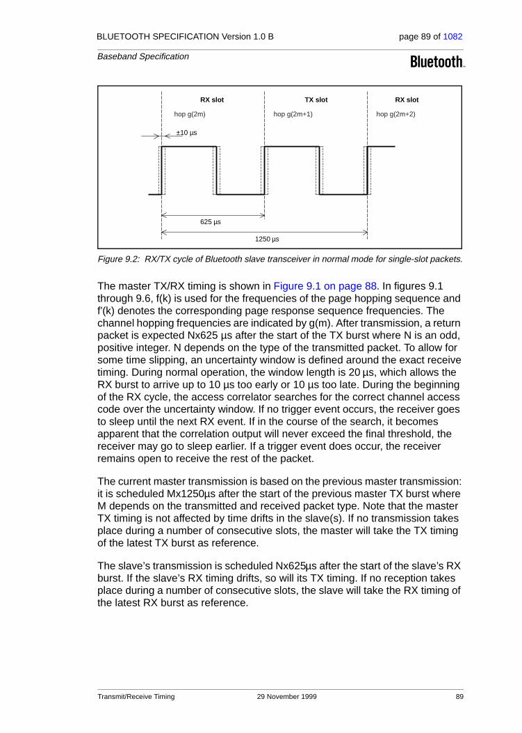
BLUETOOTH SPECIFICATION Version 1.0 B page 89 of 1082
Baseband Specification
Figure 9.2: RX/TX cycle of Bluetooth slave transceiver in normal mode for single-slot packets.
The master TX/RX timing is shown in Figure 9.1 on page 88. In figures 9.1 through 9.6, f(k) is used for the frequencies of the page hopping sequence and f’(k) denotes the corresponding page response sequence frequencies. The channel hopping frequencies are indicated by g(m). After transmission, a return packet is expected Nx625 µs after the start of the TX burst where N is an odd, positive integer. N depends on the type of the transmitted packet. To allow for some time slipping, an uncertainty window is defined around the exact receive timing. During normal operation, the window length is 20 µs, which allows the RX burst to arrive up to 10 µs too early or 10 µs too late. During the beginning of the RX cycle, the access correlator searches for the correct channel access code over the uncertainty window. If no trigger event occurs, the receiver goes to sleep until the next RX event. If in the course of the search, it becomes apparent that the correlation output will never exceed the final threshold, the receiver may go to sleep earlier. If a trigger event does occur, the receiver remains open to receive the rest of the packet.
The current master transmission is based on the previous master transmission: it is scheduled Mx1250µs after the start of the previous master TX burst where M depends on the transmitted and received packet type. Note that the master TX timing is not affected by time drifts in the slave(s). If no transmission takes place during a number of consecutive slots, the master will take the TX timing of the latest TX burst as reference.
The slave’s transmission is scheduled Nx625µs after the start of the slave’s RX burst. If the slave’s RX timing drifts, so will its TX timing. If no reception takes place during a number of consecutive slots, the slave will take the RX timing of the latest RX burst as reference.
625 µs
±10 µs
RX slot TX slot RX slot
1250 µs
hop g(2m) hop g(2m+1) hop g(2m+2)
Transmit/Receive Timing 29 November 1999 89

BLUETOOTH SPECIFICATION Version 1.0 B page 90 of 1082
Baseband Specification
9.3 RETURN FROM HOLD MODE
In the connection state, the Bluetooth unit can be placed in a hold mode, see Section 10.8 on page 112. In the hold mode, a Bluetooth transceiver neither transmits nor receives information. When returning to the normal operation after a hold mode in a slave Bluetooth unit, the slave must listen for the master before it may send information. In that case, the search window in the slave unit may be increased from ±10 µs to a larger value X µs as illustrated in Figure 9.3 on page 90. Note that only RX hop frequencies are used: the hop fre-quency used in the master-to-slave (RX) slot is also used in the uncertainty window extended into the preceding time interval normally used for the slave-to-master (TX) slot.
If the search window exceeds 625 µs, consecutive windows shall not be cen-tered at the start of RX hops g(2m), g(2m+2), ... g(2m+2i) (where ‘i’ is an inte-ger), but at g(2m), g(2m+4), ... g(2m+4i), or even at g(2m), g(2m+6), ...g(2m+6i) etc. to avoid overlapping search windows. The RX hop frequencies used shall correspond to the RX slot numbers.
It is recommended that single slot packets are used upon return from hold to minimize the synchronization time, especially after long hold periods that require search windows exceeding 625 µs.
Figure 9.3: RX timing of slave returning from hold state.
9.4 PARK MODE WAKE-UP
The park mode is similar to the hold mode. A parked slave periodically wakes up to listen to beacons from the master and to re-synchronize its clock offset. As in the return from hold mode, a parked slave when waking up may increase the search window from ±10 µs to a larger value X µs as illustrated in Figure 9.3 on page 90.
625 µs
RX slot
hop g(2m) hop g(2m+2)hop g(2m)hop g(2m-2)
±X µs
Estimated start of master TX
90 29 November 1999 Transmit/Receive Timing

BLUETOOTH SPECIFICATION Version 1.0 B page 91 of 1082
Baseband Specification
9.5 PAGE STATEIn the page state, the master transmits the device access code (ID packet) cor-responding to the slave to be connected, rapidly on a large number of different hop frequencies. Since the ID packet is a very short packet, the hop rate can be increased from 1600 hops/s to 3200 hops/s. In a single TX slot interval, the paging master transmits on two different hop frequencies. In a single RX slot interval, the paging transceiver listens on two different hop frequencies; see Figure 9.4 on page 91. During the TX slot, the paging unit sends an ID packet at the TX hop frequencies f(k) and f(k+1). In the RX slot, it listens for a response on the corresponding RX hop frequencies f’(k) and f’(k+1). The lis-tening periods are exactly timed 625 µs after the corresponding paging pack-ets, and include a ±10 µs uncertainty window.
Figure 9.4: RX/TX cycle of Bluetooth transceiver in PAGE mode.
9.6 FHS PACKET
At connection setup and during a master-slave switch, an FHS packet is trans-ferred from the master to the slave. This packet will establish the timing and frequency synchronization (see also Section 4.4.1.4 on page 56). After the slave unit has received the page message, it will return a response message which again consists of the ID packet and follows exactly 625 µs after the receipt of the page message. The master will send the FHS packet in the TX slot following the RX slot in which it received the slave response, according the RX/TX timing of the master. The time difference between the response and FHS message will depend on the timing of the page message the slave received. In Figure 9.5 on page 92, the slave receives the paging message sent first in the master-to-slave slot. It will then respond with an ID packet in the first half of the slave-to-master slot. The timing of the FHS packet is based on the timing of the page message sent first in the preceding master-to-slave slot: there is an exact 1250 µs delay between the first page message and the FHS packet. The packet is sent at the hop frequency f(k+1) which is the hop frequency following the hop frequency f(k) the page message was received in. In Figure 9.6 on page 92, the slave receives the paging message sent sec-ondly in the master-to-slave slot. It will then respond with an ID packet in the
±10 µs
TX slot RX slot TX slot
hop f(k) hop f(k+1) hop f'(k) hop f'(k+1) hop f(k+2)
68 µs
hop f(k+3)
312.5µs
625µs
Transmit/Receive Timing 29 November 1999 91
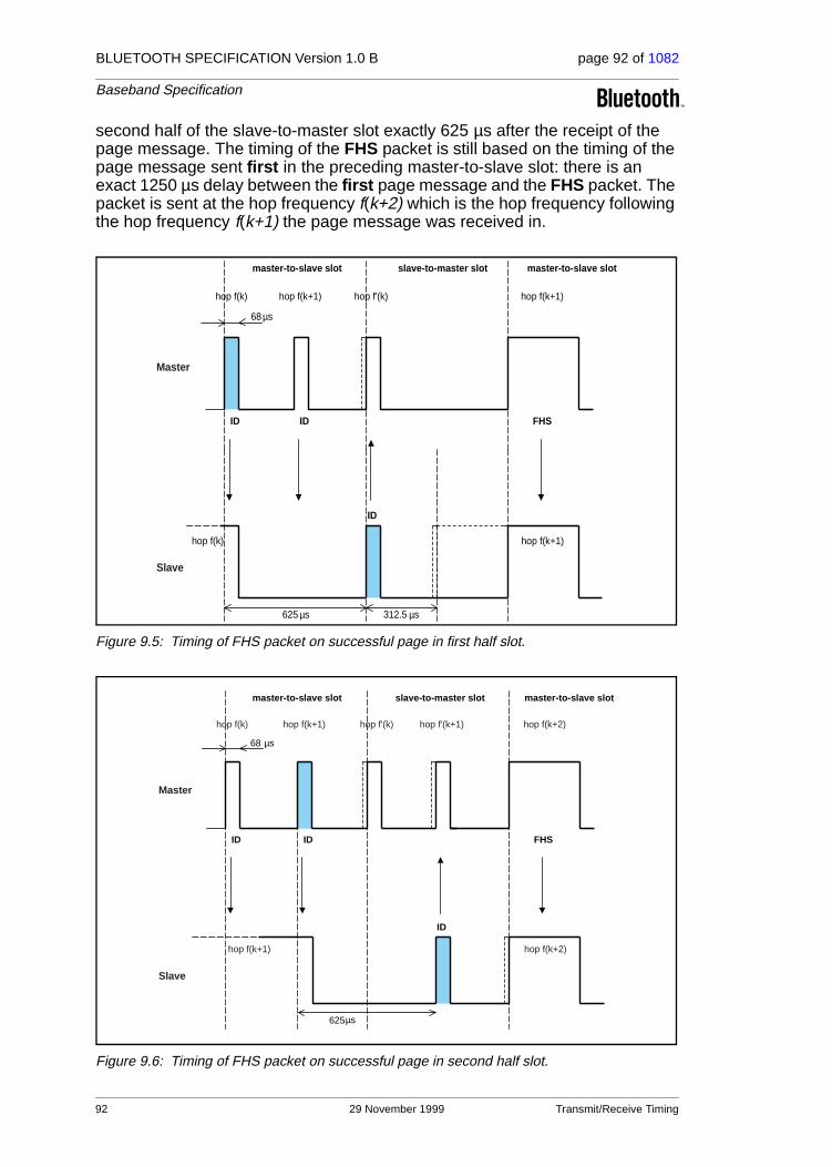
BLUETOOTH SPECIFICATION Version 1.0 B page 92 of 1082
Baseband Specification
second half of the slave-to-master slot exactly 625 µs after the receipt of the page message. The timing of the FHS packet is still based on the timing of the page message sent first in the preceding master-to-slave slot: there is an exact 1250 µs delay between the first page message and the FHS packet. The packet is sent at the hop frequency f(k+2) which is the hop frequency following the hop frequency f(k+1) the page message was received in.
Figure 9.5: Timing of FHS packet on successful page in first half slot.
Figure 9.6: Timing of FHS packet on successful page in second half slot.
master-to-slave slot slave-to-master slot master-to-slave slot
hop f(k) hop f(k+1) hop f'(k) hop f(k+1)
68 µs
625 µs 312.5 µs
ID
ID
ID FHS
hop f(k) hop f(k+1)
Master
Slave
master-to-slave slot slave-to-master slot master-to-slave slot
68 µs
625µs
ID
ID
ID FHS
Master
Slave
hop f(k) hop f'(k)hop f(k+1)
hop f(k+1)
hop f'(k+1) hop f(k+2)
hop f(k+2)
92 29 November 1999 Transmit/Receive Timing

BLUETOOTH SPECIFICATION Version 1.0 B page 93 of 1082
Baseband Specification
The slave will adjust its RX/TX timing according to the reception of the FHS packet (and not according to the reception of the page message). That is, the second response message that acknowledges the reception of the FHS packet is transmitted 625 µs after the start of the FHS packet.
9.7 MULTI-SLAVE OPERATION
As was mentioned in the beginning of this chapter, the master always starts the transmission in the even-numbered slots whereas the slaves start their trans-mission in the odd-numbered slots. This means that the timing of the master and the slave(s) is shifted by one slot (625 µs), see Figure 9.7 on page 93.
Only the slave that is addressed by its AM_ADDR can return a packet in the next slave-to-master slot. If no valid AM_ADDR is received, the slave may only respond if it concerns its reserved SCO slave-to-master slot. In case of a broadcast message, no slave is allowed to return a packet (an exception is found in the access window for access requests in the park mode, see Section 10.8.4 on page 115).
Figure 9.7: RX/TX timing in multi-slave configuration
1 2 2 1TX
RX
TX
TX
RX
RXslave 2
slave 1
master
Transmit/Receive Timing 29 November 1999 93
BLUETOOTH SPECIFICATION Version 1.0 B page 94 of 1082
Baseband Specification
94 29 November 1999 Transmit/Receive Timing

BLUETOOTH SPECIFICATION Version 1.0 B page 95 of 1082
Baseband Specification
10 CHANNEL CONTROL
10.1 SCOPE
This section describes how the channel of a piconet is established and how units can be added to and released from the piconet. Several states of opera-tion of the Bluetooth units are defined to support these functions. In addition, the operation of several piconets sharing the same area, the so-called scatter-net, is discussed. A special section is attributed to the Bluetooth clock which plays a major role in the FH synchronization.
10.2 MASTER-SLAVE DEFINITION
The channel in the piconet is characterized entirely by the master of the pico-net. The Bluetooth device address (BD_ADDR) of the master determines the FH hopping sequence and the channel access code; the system clock of the master determines the phase in the hopping sequence and sets the timing. In addition, the master controls the traffic on the channel by a polling scheme.
By definition, the master is represented by the Bluetooth unit that initiates the connection (to one or more slave units). Note that the names ‘master’ and ‘slave’ only refer to the protocol on the channel: the Bluetooth units themselves are identical; that is, any unit can become a master of a piconet. Once a pico-net has been established, master-slave roles can be exchanged. This is described in more detail in Section 10.9.3 on page 123.
10.3 BLUETOOTH CLOCK
Every Bluetooth unit has an internal system clock which determines the timing and hopping of the transceiver. The Bluetooth clock is derived from a free run-ning native clock which is never adjusted and is never turned off. For synchro-nization with other units, only offsets are used that, added to the native clock, provide temporary Bluetooth clocks which are mutually synchronized. It should be noted that the Bluetooth clock has no relation to the time of day; it can there-fore be initialized at any value. The Bluetooth clock provides the heart beat of the Bluetooth transceiver. Its resolution is at least half the TX or RX slot length, or 312.5 µs. The clock has a cycle of about a day. If the clock is implemented with a counter, a 28-bit counter is required that wraps around at 228-1. The LSB ticks in units of 312.5 µs, giving a clock rate of 3.2 kHz.
The timing and the frequency hopping on the channel of a piconet is deter-mined by the Bluetooth clock of the master. When the piconet is established, the master clock is communicated to the slaves. Each slave adds an offset to its native clock to be synchronized to the master clock. Since the clocks are free-running, the offsets have to be updated regularly.
Channel Control 29 November 1999 95

BLUETOOTH SPECIFICATION Version 1.0 B page 96 of 1082
Baseband Specification
The clock determines critical periods and triggers the events in the Bluetooth receiver. Four periods are important in the Bluetooth system: 312.5 µs, 625 µs, 1.25 ms, and 1.28 s; these periods correspond to the timer bits CLK0, CLK1, CLK2, and CLK12, respectively, see Figure 10.1 on page 96. Master-to-slave transmission starts at the even-numbered slots when CLK0 and CLK1 are both zero.
Figure 10.1: Bluetooth clock.
In the different modes and states a Bluetooth unit can reside in, the clock has different appearances:
• CLKN native clock
• CLKE estimated clock
• CLK master clock
CLKN is the free-running native clock and is the reference to all other clock appearances. In states with high activity, the native clock is driven by the refer-ence crystal oscillator with worst case accuracy of +/-20ppm. In the low power states, like STANDBY, HOLD, PARK, the native clock may be driven by a low power oscillator (LPO) with relaxed accuracy (+/-250ppm).
CLKE and CLK are derived from the reference CLKN by adding an offset. CLKE is a clock estimate a paging unit makes of the native clock of the recipi-ent; i.e. an offset is added to the CLKN of the pager to approximate the CLKN of the recipient, see Figure 10.2 on page 97. By using the CLKN of the recipi-ent, the pager speeds up the connection establishment.
CLK is the master clock of the piconet. It is used for all timing and scheduling activities in the piconet. All Bluetooth devices use the CLK to schedule their transmission and reception. The CLK is derived from the native clock CLKN by adding an offset, see Figure 10.3 on page 97. The offset is zero for the master since CLK is identical to its own native clock CLKN. Each slave adds an appro-priate offset to its CLKN such that the CLK corresponds to the CLKN of the master. Although all CLKNs in the Bluetooth devices run at the same nominal rate, mutual drift causes inaccuracies in CLK. Therefore, the offsets in the slaves must be regularly updated such that CLK is approximately CLKN of the master.
µs
µs
12 11 10 6789 5 4 3 2 1 027
1.25ms
1.28s
625
312.5
3.2kHzCLK
96 29 November 1999 Channel Control

BLUETOOTH SPECIFICATION Version 1.0 B page 97 of 1082
Baseband Specification
Figure 10.2: Derivation of CLKE
Figure 10.3: Derivation of CLK in master (a) and in slave (b).
10.4 OVERVIEW OF STATES
Figure 10.4 on page 98 shows a state diagram illustrating the different states used in the Bluetooth link controller. There are two major states: STANDBY and CONNECTION; in addition, there are seven substates, page, page scan, inquiry, inquiry scan, master response, slave response, and inquiry response. The substates are interim states that are used to add new slaves to a piconet. To move from one state to the other, either commands from the Blue-tooth link manager are used, or internal signals in the link controller are used (such as the trigger signal from the correlator and the timeout signals).
CLKN(pager) CLKE ≈ CLKN (recipient)
Estimated offset
CLKN(master) CLK
0
CLKN(slave) CLK
offset
(a) (b)
Channel Control 29 November 1999 97
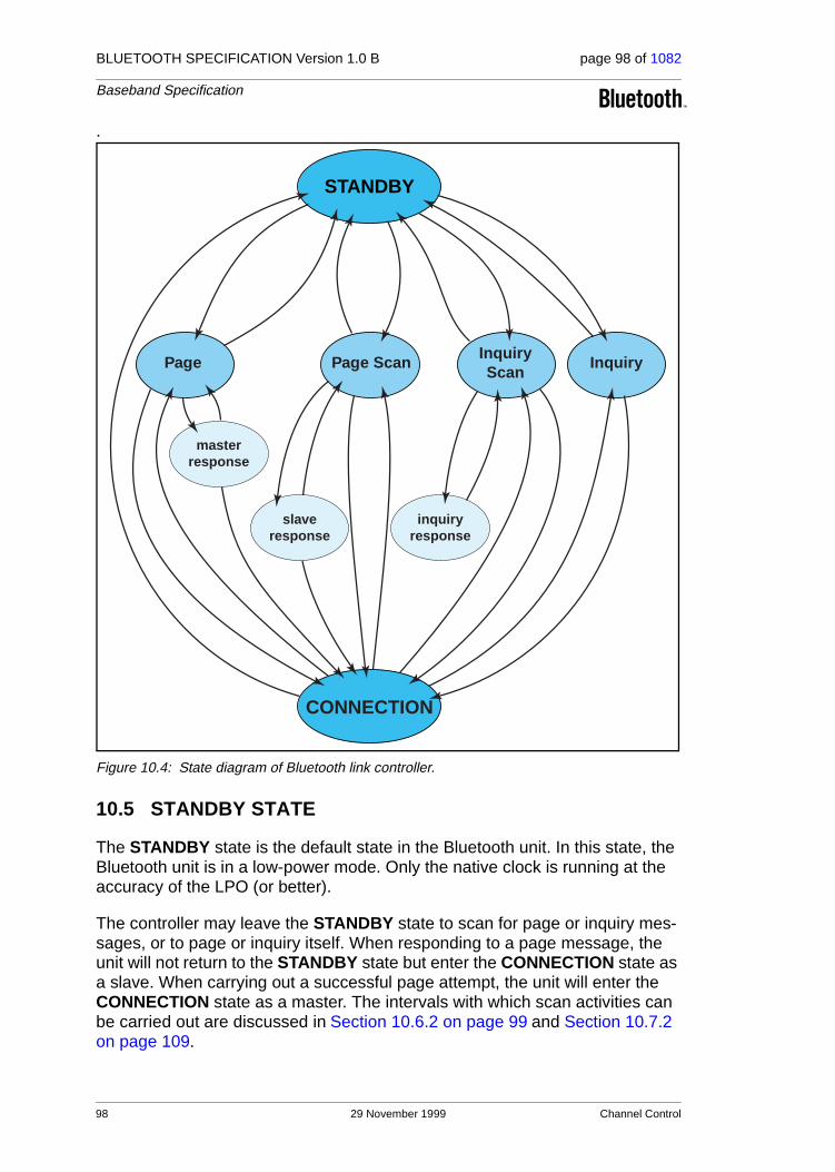
BLUETOOTH SPECIFICATION Version 1.0 B page 98 of 1082
Baseband Specification
.
Figure 10.4: State diagram of Bluetooth link controller.
10.5 STANDBY STATE
The STANDBY state is the default state in the Bluetooth unit. In this state, the Bluetooth unit is in a low-power mode. Only the native clock is running at the accuracy of the LPO (or better).
The controller may leave the STANDBY state to scan for page or inquiry mes-sages, or to page or inquiry itself. When responding to a page message, the unit will not return to the STANDBY state but enter the CONNECTION state as a slave. When carrying out a successful page attempt, the unit will enter the CONNECTION state as a master. The intervals with which scan activities can be carried out are discussed in Section 10.6.2 on page 99 and Section 10.7.2 on page 109.
Page scan
Slave response
Connection State
Master response
Page
Standby State
Inquiry
Inquiry response
Inquiry scan
CONNECTION
STANDBY
Page Page ScanInquiryScan
masterresponse
inquiryresponse
Inquiry
slaveresponse
98 29 November 1999 Channel Control

BLUETOOTH SPECIFICATION Version 1.0 B page 99 of 1082
Baseband Specification
10.6 ACCESS PROCEDURES
10.6.1 General
In order to establish new connections the procedures inquiry and paging are used. The inquiry procedure enables a unit to discover which units are in range, and what their device addresses and clocks are. With the paging proce-dure, an actual connection can be established. Only the Bluetooth device address is required to set up a connection. Knowledge about the clock will accelerate the setup procedure. A unit that establishes a connection will carry out a page procedure and will automatically be the master of the connection.
In the paging and inquiry procedures, the device access code (DAC) and the inquiry access code (IAC) are used, respectively. A unit in the page scan or inquiry scan substate correlates against these respective access codes with a matching correlator.
For the paging process, several paging schemes can be applied. There is one mandatory paging scheme which has to be supported by each Bluetooth device. This mandatory scheme is used when units meet for the first time, and in case the paging process directly follows the inquiry process. Two units, once connected using a mandatory paging/scanning scheme, may agree on an optional paging/scanning scheme. Optional paging schemes are discussed in “Appendix VII” on page 999. In the current chapter, only the mandatory paging scheme is considered.
10.6.2 Page scan
In the page scan substate, a unit listens for its own device access code for the duration of the scan window Tw page scan. During the scan window, the unit lis-tens at a single hop frequency, its correlator matched to its device access code. The scan window shall be long enough to completely scan 16 page fre-quencies.
When a unit enters the page scan substate, it selects the scan frequency according to the page hopping sequence corresponding to this unit, see Sec-tion 11.3.1 on page 135. This is a 32-hop sequence (or a 16-hop sequence in case of a reduced-hop system) in which each hop frequency is unique. The page hopping sequence is determined by the unit’s Bluetooth device address (BD_ADDR). The phase in the sequence is determined by CLKN16-12 of the unit’s native clock (CLKN15-12 in case of a reduced-hop system); that is, every 1.28s a different frequency is selected.
If the correlator exceeds the trigger threshold during the page scan, the unit will enter the slave response substate, which is described in Section 10.6.4.1 on page 105.
Channel Control 29 November 1999 99

BLUETOOTH SPECIFICATION Version 1.0 B page 100 of 1082
Baseband Specification
The page scan substate can be entered from the STANDBY state or the CON-NECTION state. In the STANDBY state, no connection has been established and the unit can use all the capacity to carry out the page scan. Before enter-ing the page scan substate from the CONNECTION state, the unit preferably reserves as much capacity for scanning. If desired, the unit may place ACL connections in the HOLD mode or even use the PARK mode, see Section 10.8.3 on page 114 and Section 10.8.4 on page 115. SCO connections are preferably not interrupted by the page scan. In this case, the page scan may be interrupted by the reserved SCO slots which have higher priority than the page scan. SCO packets should be used requiring the least amount of capac-ity (HV3 packets). The scan window shall be increased to minimize the setup delay. If one SCO link is present using HV3 packets and TSCO=6 slots, a total scan window Tw page scan of at least 36 slots (22.5ms) is recommended; if two SCO links are present using HV3 packets and TSCO=6 slots, a total scan win-dow of at least 54 slots (33.75ms) is recommended.
The scan interval Tpage scan is defined as the interval between the beginnings of two consecutive page scans. A distinction is made between the case where the scan interval is equal to the scan window Tw page scan (continuous scan), the scan interval is maximal 1.28s, or the scan interval is maximal 2.56s. These three cases determine the behavior of the paging unit; that is, whether the pag-ing unit shall use R0, R1 or R2, see also Section 10.6.3 on page 101. Table 10.1 illustrates the relationship between Tpage scan and modes R0, R1 and R2. Although scanning in the R0 mode is continuous, the scanning may be interrupted by for example reserved SCO slots. The scan interval information is included in the SR field in the FHS packet.
100 29 November 1999 Channel Control

BLUETOOTH SPECIFICATION Version 1.0 B page 101 of 1082
Baseband Specification
During page scan the Bluetooth unit may choose to use an optional scanning scheme. (An exception is the page scan after returning an inquiry response message. See Section 10.7.4 on page 111 for details.)
10.6.3 Page
The page substate is used by the master (source) to activate and connect to a slave (destination) which periodically wakes up in the page scan substate. The master tries to capture the slave by repeatedly transmitting the slave’s device access code (DAC) in different hop channels. Since the Bluetooth clocks of the master and the slave are not synchronized, the master does not know exactly when the slave wakes up and on which hop frequency. Therefore, it transmits a train of identical DACs at different hop frequencies, and listens in between the transmit intervals until it receives a response from the slave.
The page procedure in the master consists of a number of steps. First, the slave’s device address is used to determine the page hopping sequence, see Section 11.3.2 on page 135. This is the sequence the master will use to reach the slave. For the phase in the sequence, the master uses an estimate of the slave’s clock. This estimate can for example be derived from timing information that was exchanged during the last encounter with this particular device (which could have acted as a master at that time), or from an inquiry procedure. With this estimate CLKE of the slave’s Bluetooth clock, the master can predict when the slave wakes up and on which hop channel.
The estimate of the Bluetooth clock in the slave can be completely wrong. Although the master and the slave use the same hopping sequence, they use different phases in the sequence and will never meet each other. To compen-sate for the clock drifts, the master will send its page message during a short time interval on a number of wake-up frequencies. It will in fact transmit also on hop frequencies just before and after the current, predicted hop frequency. During each TX slot, the master sequentially transmits on two different hop fre-quencies. Since the page message is the ID packet which is only 68 bits in length, there is ample of time (224.5 µs minimal) to switch the synthesizer. In the following RX slot, the receiver will listen sequentially to two corresponding RX hops for ID packet. The RX hops are selected according to the page_response hopping sequence. The page_response hopping sequence is strictly related to the page hopping sequence; that is: for each page hop there is a corresponding page_response hop. The RX/TX timing in the page sub-
SR mode Tpage scan Npage
R0 continuous ≥1
R1 ≤ 1.28s ≥ 128
R2 ≤ 2.56s ≥ 256
Reserved - -
Table 10.1: Relationship between scan interval, train repetition, and paging modes R0, R1 and R2.
Channel Control 29 November 1999 101

BLUETOOTH SPECIFICATION Version 1.0 B page 102 of 1082
Baseband Specification
state has been described in Section 9, see also Figure 9.4 on page 91. In the next TX slot, it will transmit on two hop frequencies different from the former ones. The synthesizer hop rate is increased to 3200 hops/s.
A distinction must be made between the 79-hop systems and the 23-hop sys-tems. First the 79-hop systems are considered. With the increased hopping rate as described above, the transmitter can cover 16 different hop frequencies in 16 slots or 10 ms. The page hopping sequence is divided over two paging trains A and B of 16 frequencies. Train A includes the 16 hop frequencies sur-rounding the current, predicted hop frequency f(k), where k is determined by the clock estimate CLKE16-12. So the first train consists of hops
f(k-8), f(k-7),...,f(k),...,f(k+7)
When the difference between the Bluetooth clocks of the master and the slave is between -8x1.28 s and +7x1.28 s, one of the frequencies used by the master will be the hop frequency the slave will listen to. However, since the master does not know when the slave will enter the page scan substate, he has to repeat this train A Npage times or until a response is obtained. If the slave scan interval corresponds to R1, the repetition number is at least 128; if the slave scan interval corresponds to R2, the repetition number is at least 256. Note that CLKE16-12 changes every 1.28 s; therefore, every 1.28 s, the trains will include different frequencies of the page hopping set.
When the difference between the Bluetooth clocks of the master and the slave is less than -8x1.28 s or larger than +7x1.28 s, more distant hops must be probed. Since in total, there are only 32 dedicated wake-up hops, the more dis-tant hops are the remaining hops not being probed yet. The remaining 16 hops are used to form the new 10 ms train B. The second train consists of hops
f(k-16), f(k-15),...,f(k-9),f(k+8)...,f(k+15)
Train B is repeated for Npage times. If still no response is obtained, the first train A is tried again Npage times. Alternate use of train A and train B is continued until a response is received or the timeout pageTO is exceeded. If during one of the listening occasions, a response is returned by the slave, the master unit enters the master response substate.
The description for paging and page scan procedures given here has been tai-lored towards the 79-hop systems used in the US and Europe. For the 23-hop systems as used in Japan and some European countries, the procedure is slightly different. In the 23-hop case, the length of the page hopping sequence is reduced to 16. As a consequence, there is only a single train (train A) includ-ing all the page hopping frequencies. The phase to the page hopping sequence is not CLKE16-12 but CLKE15-12. An estimate of the slave’s clock does not have to be made.
The page substate can be entered from the STANDBY state or the CONNEC-TION state. In the STANDBY state, no connection has been established and
102 29 November 1999 Channel Control
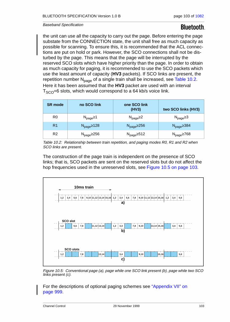
BLUETOOTH SPECIFICATION Version 1.0 B page 103 of 1082
Baseband Specification
the unit can use all the capacity to carry out the page. Before entering the page substate from the CONNECTION state, the unit shall free as much capacity as possible for scanning. To ensure this, it is recommended that the ACL connec-tions are put on hold or park. However, the SCO connections shall not be dis-turbed by the page. This means that the page will be interrupted by the reserved SCO slots which have higher priority than the page. In order to obtain as much capacity for paging, it is recommended to use the SCO packets which use the least amount of capacity (HV3 packets). If SCO links are present, the repetition number Npage of a single train shall be increased, see Table 10.2.Here it has been assumed that the HV3 packet are used with an interval TSCO=6 slots, which would correspond to a 64 kb/s voice link.
The construction of the page train is independent on the presence of SCO links; that is, SCO packets are sent on the reserved slots but do not affect the hop frequencies used in the unreserved slots, see Figure 10.5 on page 103.
Figure 10.5: Conventional page (a), page while one SCO link present (b), page while two SCO links present (c).
For the descriptions of optional paging schemes see “Appendix VII” on page 999.
SR mode no SCO link one SCO link (HV3) two SCO links (HV3)
R0 Npage≥1 Npage≥2 Npage≥3
R1 Npage≥128 Npage≥256 Npage≥384
R2 Npage≥256 Npage≥512 Npage≥768
Table 10.2: Relationship between train repetition, and paging modes R0, R1 and R2 when SCO links are present.
SCO slot
SCO slots
a)
b)
c)
10ms train
1,2 3,4 5,6 7,8 9,10 11,12 13,14 15,16 1,2 3,4 5,6 7,8 9,10 11,12 13,14 15,16 1,2 3,4 5,6
3,4 5,61,2 3,4 7,8 9,10 13,14 15,161,2 5,6 7,8 11,12 13,14
5,63,4 9,10 15,161,2 7,8 13,14
Channel Control 29 November 1999 103

BLUETOOTH SPECIFICATION Version 1.0 B page 104 of 1082
Baseband Specification
10.6.4 Page response procedures
When a page message is successfully received by the slave, there is a coarse FH synchronization between the master and the slave. Both the master and the slave enter a response routine to exchange vital information to continue the connection setup. Important for the piconet connection is that both Bluetooth units use the same channel access code, use the same channel hopping sequence, and that their clocks are synchronized. These parameters are derived from the master unit. The unit that initializes the connection (starts pag-ing) is defined as the master unit (which is thus only valid during the time the piconet exists). The channel access code and channel hopping sequence are derived from the Bluetooth device address (BD_ADDR) of the master. The tim-ing is determined by the master clock. An offset is added to the slave’s native clock to temporarily synchronize the slave clock to the master clock. At start-up, the master parameters have to be transmitted from the master to the slave. The messaging between the master and the slave at start-up will be consid-ered in this section.
The initial messaging between master and slave is shown in Table 10.3 on page 104 and in Figure 10.6 on page 105 and Figure 10.7 on page 105. In those two figures frequencies f (k), f(k+1), etc. are the frequencies of the page hopping sequence determined by the slave’s BD_ADDR. The frequencies f’(k), f’(k+1), etc. are the corresponding page_response frequencies (slave-to-mas-ter). The frequencies g(m) belong to the channel hopping sequence.
In step 1 (see Table 10.3 on page 104), the master unit is in page substate and the slave unit in the page scan substate. Assume in this step that the page message (= slave’s device access code) sent by the master reaches the slave. On recognizing its device access code, the slave enters the slave response in step 2. The master waits for a reply from the slave and when this arrives in step 2, it will enter the master response in step 3. Note that during the initial mes-sage exchange, all parameters are derived from the slave’s BD_ADDR, and that only the page hopping and page_response hopping sequences are used
Step Message DirectionHopping Sequence
Access Code and Clock
1 slave ID master to slave page slave
2 slave ID slave to master page response
slave
3 FHS master to slave page slave
4 slave ID slave to master page response
slave
5 1st packet master master to slave channel master
6 1st packet slave slave to master channel master
Table 10.3: Initial messaging during start-up.
104 29 November 1999 Channel Control

BLUETOOTH SPECIFICATION Version 1.0 B page 105 of 1082
Baseband Specification
(which are also derived from the slave’s BD_ADDR). Note that when the mas-ter and slave enter the response states, their clock input to the page and page_response hop selection is frozen as is described in Section 11.3.3 on page 136.
Figure 10.6: Messaging at initial connection when slave responds to first page message.
Figure 10.7: Messaging at initial connection when slave responds to second page message.
10.6.4.1 Slave response
After having received its own device access code in step 1, the slave unit trans-mits a response message in step 2. This response message again only con-sists of the slave’s device access code. The slave will transmit this response 625 µs after the beginning of the received page message (slave ID packet) and at the response hop frequency that corresponds to the hop frequency in which the page message was received. The slave transmission is therefore time
f(k)
f'(k)
page hopping sequence channel hopping sequence
MASTER
SLAVE
f'(k+1) g(m+1)
g(m)f(k+1)f(k+1)
PAGE
RESPONSE RESPONSE 1stTraffic
1stTRAFFIC
step 1 step 2 step 3 step 4 step 5 step 6
FHS
f(k)
page hopping sequence channel hopping sequence
MASTER
SLAVE
g(m+1)
g(m)f(k+1)
f'(k+1)
f(k+2)
f'(k+2)
PAGE
1st TRAFFICRESPONSERESPONSE
step 1 step 2 step 3 step 4 step 5 step 6
FHS 1st TRAFFIC
Channel Control 29 November 1999 105

BLUETOOTH SPECIFICATION Version 1.0 B page 106 of 1082
Baseband Specification
aligned to the master transmission. During initial messaging, the slave still uses the page response hopping sequence to return information to the master. The clock input CLKN16-12 is frozen at the value it had at the time the page message was received.
After having sent the response message, the slave’s receiver is activated (312.5 µs after the start of the response message) and awaits the arrival of a FHS packet. Note that a FHS packet can already arrive 312.5 µs after the arrival of the page message as shown in Figure 10.7 on page 105, and not after 625 µs as is usually the case in the RX/TX timing. More details about the timing can be found in Section 9.6 on page 91.
If the setup fails before the CONNECTION state has been reached, the follow-ing procedure is carried out. The slave will keep listening as long as no FHS packet is received until pagerespTO is exceeded. Every 1.25 ms, however, it will select the next master-to-slave hop frequency according to the page hop sequence. If nothing is received after pagerespTO, the slave returns back to the page scan substate for one scan period. Length of the scan period depends on the SCO slots present. If no page message is received during this additional scan period, the slave will resume scanning at its regular scan inter-val and return to the state it was in prior to the first page scan state.
If a FHS packet is received by the slave in the slave response substate, the slave returns a response (slave’s device access code only) in step 4 to acknowledge the reception of the FHS packet (still using the page response hopping sequence). The transmission of this response packet is based on the reception of the FHS packet. Then the slave changes to the channel (master’s) access code and clock as received from the FHS packet. Only the 26 MSBs of the master clock are transferred: the timing is assumed such that CLK1 and CLK0 are both zero at the time the FHS packet was received as the master transmits in even slots only. From the master clock in the FHS packet, the off-set between the master’s clock and the slave’s clock is determined and reported to the slave’s link manager.
Finally, the slave enters the CONNECTION state in step 5. From then on, the slave will use the master’s clock and the master BD_ADDR to determine the channel hopping sequence and the channel access code. The connection mode starts with a POLL packet transmitted by the master. The slave responds with any type of packet. If the POLL packet is not received by the slave, or the response packet is not received by the master, within newconnectionTO num-ber of slots after FHS packet acknowledgement, the master and the slave will return to page and page scan substates, respectively.See Section 10.8 on page 112
106 29 November 1999 Channel Control

BLUETOOTH SPECIFICATION Version 1.0 B page 107 of 1082
Baseband Specification
10.6.4.2 Master response
When the master has received a response message from the slave in step 2, it will enter the master response routine. It freezes the current clock input to the page hop selection scheme. Then the master will transmit a FHS packet in step 3 containing the master’s real-time Bluetooth clock, the master’s 48-bit BD_ADDR address, the BCH parity bits, and the class of device. The FHS packet contains all information to construct the channel access code without requiring a mathematical derivation from the master device address. The FHS packet is transmitted at the beginning of the master-to-slave slot following the slot in which the slave has responded. So the TX timing of the FHS is not based on the reception of the response packet from the slave. The FHS packet may therefore be sent 312.5 µs after the reception of the response packet like shown in Figure 10.7 on page 105 and not 625 µs after the received packet as is usual in the RX/TX timing, see also Section 9.6 on page 91.
After the master has sent its FHS packet, it waits for a second response from the slave in step 4 which acknowledges the reception of the FHS packet. Again this is only the slave’s device access code. If no response is received, the mas-ter retransmits the FHS packet, but with an updated clock and still using the slave’s parameters. It will retransmit (the clock is updated every retransmis-sion) until a second slave response is received, or the timeout of pagerespTO is exceeded. In the latter case, the master turns back to the page substate and sends an error message to the link manager. During the retransmissions of the FHS packet, the master keeps using the page hopping sequence.
If the slave’s response is indeed received, the master changes to the master parameters, so the channel access code and the master clock. The lower clock bits CLK0 and CLK1 are zero at the start of the FHS packet transmission and are not included in the FHS packet. Finally, the master enters the CONNEC-TION state in step 5. The master BD_ADDR is used to change to a new hop-ping sequence, the channel hopping sequence. The channel hopping sequence uses all 79 hop channels in a (pseudo) random fashion, see also Section 11.3.6 on page 138. The master can now send its first traffic packet in a hop determined with the new (master) parameters. This first packet will be a POLL packet. See Section 10.8 on page 112.
The master can now send its first traffic packet in a hop determined with the new (master) parameters. The first packet in this state is a POLL packet sent by the master. This packet will be sent within newconnectionTO number of slots after reception of the FHS packet acknowledgement. The slave will respond with any type of packet. If the POLL packet is not received by the slave or the POLL packet response is not received by the master within new-connectionTO number of slots, the master and the slave will return to page and page scan substates, respectively.
Channel Control 29 November 1999 107

BLUETOOTH SPECIFICATION Version 1.0 B page 108 of 1082
Baseband Specification
10.7 INQUIRY PROCEDURES
10.7.1 General
In the Bluetooth system, an inquiry procedure is defined which is used in appli-cations where the destination’s device address is unknown to the source. One can think of public facilities like printers or facsimile machines, or access points to a LAN. Alternatively, the inquiry procedure can be used to discover which other Bluetooth units are within range. During an inquiry substate, the discov-ering unit collects the Bluetooth device addresses and clocks of all units that respond to the inquiry message. It can then, if desired, make a connection to any one of them by means of the previously described page procedure.
The inquiry message broadcasted by the source does not contain any informa-tion about the source. However, it may indicate which class of devices should respond. There is one general inquiry access code (GIAC) to inquire for any Bluetooth device, and a number of dedicated inquiry access codes (DIAC) that only inquire for a certain type of devices. The inquiry access codes are derived from reserved Bluetooth device addresses and are further described in Section 4.2.1.
A unit that wants to discover other Bluetooth units enters an inquiry substate. In this substate, it continuously transmits the inquiry message (which is the ID packet, see Section 4.4.1.1 on page 55) at different hop frequencies. The inquiry hop sequence is always derived from the LAP of the GIAC. Thus, even when DIACs are used, the applied hopping sequence is generated from the GIAC LAP. A unit that allows itself to be discovered, regularly enters the inquiry scan substate to respond to inquiry messages. The following sections describe the message exchange and contention resolution during inquiry response. The inquiry response is optional: a unit is not forced to respond to an inquiry message.
108 29 November 1999 Channel Control
BLUETOOTH SPECIFICATION Version 1.0 B page 109 of 1082
Baseband Specification
10.7.2 Inquiry scan
The inquiry scan substate is very similar to the page scan substate. However, instead of scanning for the unit’s device access code, the receiver scans for the inquiry access code long enough to completely scan for 16 inquiry frequencies. The length of this scan period is denoted Tw_inquiry_scan. The scan is performed at a single hop frequency. As in the page procedure, the inquiry procedure uses 32 dedicated inquiry hop frequencies according to the inquiry hopping sequence. These frequencies are determined by the general inquiry address. The phase is determined by the native clock of the unit carrying out the inquiry scan; the phase changes every 1.28s.
Instead or in addition to the general inquiry access code, the unit may scan for one or more dedicated inquiry access codes. However, the scanning will follow the inquiry hopping sequence which is determined by the general inquiry address. If an inquiry message is recognized during an inquiry wake-up period, the Bluetooth unit enters the inquiry response substate.
The inquiry scan substate can be entered from the STANDBY state or the CONNECTION state. In the STANDBY state, no connection has been estab-lished and the unit can use all the capacity to carry out the inquiry scan. Before entering the inquiry scan substate from the CONNECTION state, the unit preferably reserves as much capacity as possible for scanning. If desired, the unit may place ACL connections in the HOLD mode or even use the PARK mode, see Section 10.8.3 on page 114. SCO connections are preferably not interrupted by the inquiry scan. In this case, the inquiry scan may be inter-rupted by the reserved SCO slots which have higher priority than the inquiry scan. SCO packets should be used requiring the least amount of capacity (HV3 packets). The scan window, Tw inquiry scan, shall be increased to increase the probability to respond to an inquiry message. If one SCO link is present using HV3 packets and TSCO=6 slots, a total scan window of at least 36 slots (22.5ms) is recommended; if two SCO links are present using HV3 packets and TSCO=6 slots, a total scan window of at least 54 slots (33.75ms) is recom-mended.
The scan interval Tinquiry scan is defined as the interval between two consecu-tive inquiry scans. The inquiry scan interval shall be at most 2.56 s.
Channel Control 29 November 1999 109

BLUETOOTH SPECIFICATION Version 1.0 B page 110 of 1082
Baseband Specification
10.7.3 Inquiry
The inquiry substate is used by the unit that wants to discover new devices. This substate is very similar to the page substate, the same TX/RX timing is used as used for paging, see Section 9.6 on page 91 and Figure 9.4 on page 91. The TX and RX frequencies follow the inquiry hopping sequence and the inquiry response hopping sequence, and are determined by the general inquiry access code and the native clock of the discovering device. In between inquiry transmissions, the Bluetooth receiver scans for inquiry response messages. When found, the entire response packet (which is in fact a FHS packet) is read, after which the unit continues with the inquiry transmissions. So the Bluetooth unit in an inquiry substate does not acknowledge the inquiry response mes-sages. It keeps probing at different hop channels and in between listens for response packets. Like in the page substate, two 10 ms trains A and B are defined, splitting the 32 frequencies of the inquiry hopping sequence into two 16-hop parts. A single train must be repeated for at least Ninquiry=256 times before a new train is used. In order to collect all responses in an error-free environment, at least three train switches must have taken place. As a result, the inquiry substate may have to last for 10.24 s unless the inquirer collects enough responses and determines to abort the inquiry substate earlier. If desired, the inquirer can also prolong the inquiry substate to increase the probability of receiving all responses in an error-prone environment. If an inquiry procedure is automatically initiated periodically (say a 10 s period every minute), then the interval between two inquiry instances must be determined randomly. This is done to avoid two Bluetooth units to synchronize their inquiry procedures.
The inquiry substate is continued until stopped by the Bluetooth link manager (when it decides that it has sufficient number of responses), or when a timeout has been reached (inquiryTO).
The inquiry substate can be entered from the STANDBY state or the CON-NECTION state. In the STANDBY state, no connection has been established and the unit can use all the capacity to carry out the inquiry. Before entering the inquiry substate from the CONNECTION state, the unit shall free as much capacity as possible for scanning. To ensure this, it is recommended that the ACL connections are put on hold or park. However, the SCO connections shall not be disturbed by the inquiry. This means that the inquiry will be interrupted by the reserved SCO slots which have higher priority than the inquiry. In order to obtain as much capacity for inquiry, it is recommended to use the SCO pack-ets which use the least amount of capacity (HV3 packets). If SCO links are present, the repetition number Ninquiry shall be increased, see Table 10.4 on page 111.Here it has been assumed that the HV3 packet are used with an interval TSCO=6 slots, which would correspond to a 64 kb/s voice link.
110 29 November 1999 Channel Control

BLUETOOTH SPECIFICATION Version 1.0 B page 111 of 1082
Baseband Specification
10.7.4 Inquiry response
For the inquiry operation, there is only a slave response, no master response. The master listens between inquiry messages for responses, but after reading a response, it continues to transmit inquiry messages. The slave response rou-tine for inquiries differs completely from the slave response routine applied for pages. When the inquiry message is received in the inquiry scan substate, a response message containing the recipient’s address must be returned. This response message is a conventional FHS packet carrying the unit’s parame-ters. However, a contention problem may arise when several Bluetooth units are in close proximity to the inquiring unit and all respond to an inquiry mes-sage at the same time. First of all, every Bluetooth unit has a free running clock; therefore, it is highly unlikely that they all use the same phase of the inquiry hopping sequence. However, in order to avoid collisions between units that do wake up in the same inquiry hop channel simultaneously, the following protocol in the slave’s inquiry response is used. If the slave receives an inquiry message, it generates a random number RAND between 0 and 1023. In addition, it freezes the current input value (phase) to the hop selection scheme, see also Section 11.3.5 on page 137. The slave then returns to the CONNEC-TION or STANDBY state for the duration of RAND time slots. Before returning to the CONNECTION or STANDBY state, the unit may go through the page scan substate; this page scan must use the mandatory page scan scheme. After at least RAND slots, the unit will return to the inquiry response substate. On the first inquiry message received the slave returns an FHS response packet to the master. If during the scan no trigger occurs within a timeout period of inqrespTO, the slave returns to the STANDBY or CONNECTION state. If the unit does receive an inquiry message and returns an FHS packet, it adds an offset of 1 to the phase in the inquiry hop sequence (the phase has a 1.28 s resolution) and enters the inquiry scan substate again. If the slave is triggered again, it repeats the procedure using a new RAND. The offset to the clock accumulates each time a FHS packet is returned. During a 1.28 s probing window, a slave on average responses 4 times, but on different frequencies and at different times. Possible SCO slots should have priority over response packets; that is, if a response packet overlaps with an SCO slot, it is not sent but the next inquiry message is awaited.
The messaging during the inquiry routines is summarized in Table 10.5 on page 112. In step 1, the master transmits an inquiry message using the inquiry access code and its own clock. The slave responds with the FHS packet which contains the slave’s device address, native clock and other slave information. This FHS packet is returned at a semi-random time. The FHS packet is not acknowledged in the inquiry routine, but it is retransmitted at other times and frequencies as long as the master is probing with inquiry messages.
no SCO link one SCO link (HV3) two SCO links (HV3)
Ninquiry ≥ 256 ≥ 512 ≥ 768
Table 10.4: Increase of train repetition when SCO links are present.
Channel Control 29 November 1999 111

BLUETOOTH SPECIFICATION Version 1.0 B page 112 of 1082
Baseband Specification
If the scanning unit uses an optional scanning scheme, after responding to an inquiry with an FHS packet, it will perform page scan using the mandatory page scan scheme for Tmandatory pscan period. Every time an inquiry response is sent the unit will start a timer with a timeout of Tmandatory pscan. The timer will be reset at each new inquiry response. Until the timer times out, when the unit per-forms page scan, it will use the mandatory page scanning scheme in the SR mode it uses for all its page scan intervals. Using the mandatory page scan scheme after the inquiry procedure enables all units to connect even if they do not support an optional paging scheme (yet). In addition to using the manda-tory page scan scheme, an optional page scan scheme can be used in parallel for the Tmandatory pscan period.
The Tmandatory pscan period is included in the SP field of the FHS packet returned in the inquiry response routine, see Section 4.4.1.4 on page 56. The value of the period is indicated in the Table 10.6
10.8 CONNECTION STATE
In the CONNECTION state, the connection has been established and packets can be sent back and forth. In both units, the channel (master) access code and the master Bluetooth clock are used. The hopping scheme uses the chan-nel hopping sequence. The master starts its transmission in even slots (CLK1-
0=00), the slave starts its transmission in odd slots (CLK1-0=10)
The CONNECTION state starts with a POLL packet sent by the master to ver-ify the switch to the master’s timing and channel frequency hopping. The slave can respond with any type of packet. If the slave does not receive the POLL packet or the master does not receive the response packet for newconnecti-onTO number of slots, both devices will return to page/page scan substates.
step message direction hopping sequence access code
1 ID master to slave inquiry inquiry
2 FHS slave to master inquiry response inquiry
Table 10.5: Messaging during inquiry routines.
SP mode Tmandatory pscan
P0 ≥20s
P1 ≥ 40s
P2 ≥ 60s
Reserved -
Table 10.6: Mandatory scan periods for P0, P1, P2 scan period modes.
112 29 November 1999 Channel Control

BLUETOOTH SPECIFICATION Version 1.0 B page 113 of 1082
Baseband Specification
The first information packets in the CONNECTION state contain control mes-sages that characterize the link and give more details regarding the Bluetooth units. These messages are exchanged between the link managers of the units. For example, it defines the SCO links and the sniff parameters. Then the trans-fer of user information can start by alternately transmitting and receiving pack-ets.
The CONNECTION state is left through a detach or reset command. The detach command is used if the link has been disconnected in the normal way. All configuration data in the Bluetooth link controller is still valid. The reset command is a hard reset of all controller processes. After a reset, the controller has to be reconfigured.
The Bluetooth units can be in several modes of operation during the CONNEC-TION state: active mode, sniff mode, hold mode, and park mode. These modes are now described in more detail.
10.8.1 Active mode
In the active mode, the Bluetooth unit actively participates on the channel. The master schedules the transmission based on traffic demands to and from the different slaves. In addition, it supports regular transmissions to keep slaves synchronized to the channel. Active slaves listen in the master-to-slave slots for packets. If an active slave is not addressed, it may sleep until the next new master transmission. From the type indication in the packet, the number of slots the master has reserved for its transmission can be derived; during this time, the non-addressed slaves do not have to listen on the master-to-slave slots. A periodic master transmission is required to keep the slaves synchro-nized to the channel. Since the slaves only need the channel access code to synchronize with, any packet type can be used for this purpose.
Channel Control 29 November 1999 113

BLUETOOTH SPECIFICATION Version 1.0 B page 114 of 1082
Baseband Specification
10.8.2 Sniff mode
In the sniff mode, the duty cycle of the slave’s listen activity can be reduced. If a slave participates on an ACL link, it has to listen in every ACL slot to the mas-ter traffic. With the sniff mode, the time slots where the master can start trans-mission to a specific slave is reduced; that is, the master can only start transmission in specified time slots. These so-called sniff slots are spaced reg-ularly with an interval of Tsniff.
The slave has to listen at Dsniff slot every sniff period, Tsniff for a Nsniff attempt number of times. If the slave receives a packet in one of the Nsniff attempt RX slots, it should continue listening as long as it receives packets to its own AM_ADDR. Once it stops receiving packets, it should continue listening for Nsniff timeout RX slots or remaining of the Nsniff attempt number of RX slots, whichever is greater.
To enter the sniff mode, the master shall issue a sniff command via the LM pro-tocol. This message will contain the sniff interval Tsniff and an offset Dsniff. The timing of the sniff mode is then determined similar as for the SCO links. In addi-tion, an initialization flag indicates whether initialization procedure 1 or 2 is being used. The master uses initialization 1 when the MSB of the current mas-ter clock (CLK27) is 0; it uses initialization 2 when the MSB of the current mas-ter clock (CLK27) is 1. The slave shall apply the initialization method as indicated by the initialization flag irrespective of its clock bit value CLK27. The master-to-slave sniff slots determined by the master and the slave shall be ini-tialized on the slots for which the clock satisfies the following equation
CLK27-1 mod Tsniff = Dsniff for initialization 1
(CLK27,CLK26-1) mod Tsniff = Dsniff for initialization 2
The slave-to-master sniff slot determined by the master and the slave shall be initialized on the slots after the master-to-slave sniff slot defined above. After initialization, the clock value CLK(k+1) for the next master-to-slave SNIFF slot is found by adding the fixed interval Tsniff to the clock value of the current mas-ter-to-slave sniff slot:
CLK(k+1) = CLK(k) + Tsniff
10.8.3 Hold mode
During the CONNECTION state, the ACL link to a slave can be put in a hold mode. This means that the slave temporarily does not support ACL packets on the channel any more (note: possible SCO links will still be supported). With the hold mode, capacity can be made free to do other things like scanning, paging, inquiring, or attending another piconet. The unit in hold mode can also enter a low-power sleep mode. During the hold mode, the slave unit keeps its active member address (AM_ADDR).
114 29 November 1999 Channel Control
BLUETOOTH SPECIFICATION Version 1.0 B page 115 of 1082
Baseband Specification
Prior to entering the hold mode, master and slave agree on the time duration the slave remains in the hold mode. A timer is initialized with the holdTO value. When the timer is expired, the slave will wake up, synchronize to the traffic on the channel and will wait for further master instructions.
10.8.4 Park mode
When a slave does not need to participate on the piconet channel, but still wants to remain synchronized to the channel, it can enter the park mode which is a low-power mode with very little activity in the slave. In the park mode, the slave gives up its active member address AM_ADDR. Instead, it receives two new addresses to be used in the park mode
• PM_ADDR: 8-bit Parked Member Address
• AR_ADDR: 8-bit Access Request Address
The PM_ADDR distinguishes a parked slave from the other parked slaves. This address is used in the master-initiated unpark procedure. In addition to the PM_ADDR, a parked slave can also be unparked by its 48-bit BD_ADDR. The all-zero PM_ADDR is a reserved address: if a parked unit has the all-zero PM_ADDR it can only be unparked by the BD_ADDR. In that case, the PM_ADDR has no meaning. The AR_ADDR is used by the slave in the slave-initiated unpark procedure. All messages sent to the parked slaves have to be carried by broadcast packets (the all-zero AM_ADDR) because of the missing AM_ADDR.
The parked slave wakes up at regular intervals to listen to the channel in order to re-synchronize and to check for broadcast messages. To support the syn-chronization and channel access of the parked slaves, the master supports a beacon channel described in the next section. The beacon structure is commu-nicated to the slave when it is being parked. When the beacon structure changes, the parked slaves are updated through broadcast messages.
In addition for using it for low power consumption, the park mode is used to connect more than seven slaves to a single master. At any one time, only seven slaves can be active. However, by swapping active and parked slaves out respectively in the piconet, the number of slave virtually connected can be much larger (255 if the PM_ADDR is used, and even a larger number if the BD_ADDR is used). There is no limitation to the number of slaves that can be parked.
10.8.4.1 Beacon channel
To support parked slaves, the master establishes a beacon channel when one or more slaves are parked. The beacon channel consists of one beacon slot or a train of equidistant beacon slots which is transmitted periodically with a con-stant time interval. The beacon channel is illustrated in Figure 10.8 on page 117. A train of NB (NB ≥ 1) beacon slots is defined with an interval of TB slots.
Channel Control 29 November 1999 115

BLUETOOTH SPECIFICATION Version 1.0 B page 116 of 1082
Baseband Specification
The beacon slots in the train are separated by ∆B. The start of the first beacon slot is referred to as the beacon instant and serves as the beacon timing refer-ence. The beacon parameters NB and TB are chosen such that there are suffi-cient beacon slots for a parked slave to synchronize to during a certain time window in an error-prone environment.
When parked, the slave will receive the beacon parameters through an LMP command. In addition, the timing of the beacon instant is indicated through the offset DB. Like for the SCO link (see Section 3.2 on page 45), two initialization procedures 1 or 2 are used. The master uses initialization 1 when the MSB of the current master clock (CLK27) is 0; it uses initialization 2 when the MSB of the current master clock (CLK27) is 1. The chosen initialization procedure is also carried by an initialization flag in the LMP command. The slave shall apply the initiations method as indicated by the initialization flag irrespective of its clock bit CLK27. The master-to-slave slot positioned at the beacon instant shall be initialized on the slots for which the clock satisfies the following equation
CLK27-1 mod TB = DB for initialization 1
(CLK27,CLK26-1) mod TB = DB for initialization 2
After initialization, the clock value CLK(k+1) for the next beacon instant is found by adding the fixed interval TB to the clock value of the current beacon instant:
CLK(k+1) = CLK(k) + TB
The beacon channel serves four purposes:
1. transmission of master-to-slave packets which the parked slaves can use for re-synchronization
2. carrying messages to the parked slaves to change the beacon parameters
3. carrying general broadcast messages to the parked slaves
4. unparking of one or more parked slaves
Since a slave can synchronize to any packet which is preceded by the proper channel access code, the packets carried on the beacon slots do not have to contain specific broadcast packets for parked slaves to be able to synchronize; any packet can be used. The only requirement placed on the beacon slots is that there is master-to-slave transmission present. If there is no information to be sent, NULL packets can be transmitted by the master. If there is indeed broadcast information to be sent to the parked slaves, the first packet of the broadcast message shall be repeated in every beacon slot of the beacon train. However, synchronous traffic like on the SCO link, may interrupt the beacon transmission.
116 29 November 1999 Channel Control

BLUETOOTH SPECIFICATION Version 1.0 B page 117 of 1082
Baseband Specification
Figure 10.8: General beacon channel format
10.8.4.2 Beacon access window
In addition to the beacon slots, an access window is defined where the parked slaves can send requests to be unparked. To increase reliability, the access window can be repeated Maccess times (Maccess ≥1), see Figure 10.9 on page 117. The access window starts a fixed delay Daccess after the beacon instant. The width of the access window is Taccess.
Figure 10.9: Definition of access window
The access window may support different slave access techniques, like polling, random access, or other forms of access. At this stage, only the polling tech-nique has been defined. The format of the polling technique is shown in Figure 10.10 on page 118. The same TDD structure is used as on the piconet chan-nel, i.e. master-to-slave transmission is alternated by slave-to-master transmis-sion. The slave-to-master slot is divided into two half slots of 312.5 µs each. The half slot a parked slave is allowed to respond in corresponds to its access request address (AR_ADDR), see also section 10.8.4.6 on page 120. For counting the half slots to determine the access request slot, the start of the access window is used, see Figure 10.10 on page 118. The slave is only allowed to send an access request in the proper slave-to-master half slot if in the preceding master-to-slave slot a broadcast packet has been received. In this way, the master polls the parked slaves.
1 2 NB
TB
B
1 2 NB
beacon instant
beacon slots
t
1 2 NB
Daccess
Taccess
t
access window 1 access window 2 access window Maccess
beacon instant
Channel Control 29 November 1999 117
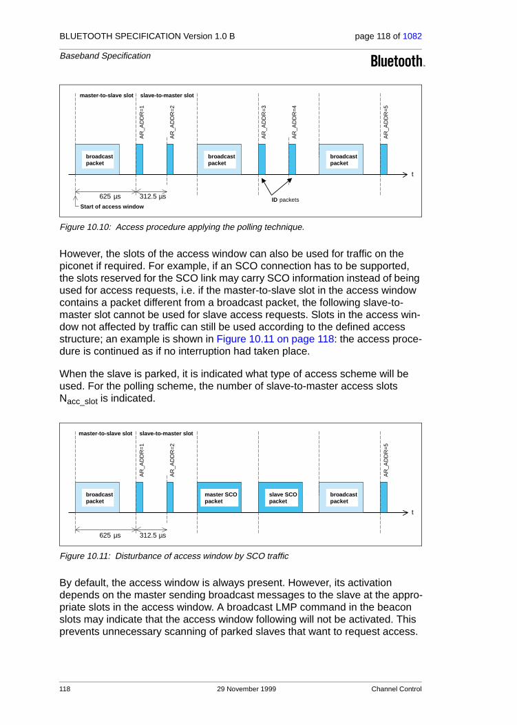
BLUETOOTH SPECIFICATION Version 1.0 B page 118 of 1082
Baseband Specification
Figure 10.10: Access procedure applying the polling technique.
However, the slots of the access window can also be used for traffic on the piconet if required. For example, if an SCO connection has to be supported, the slots reserved for the SCO link may carry SCO information instead of being used for access requests, i.e. if the master-to-slave slot in the access window contains a packet different from a broadcast packet, the following slave-to-master slot cannot be used for slave access requests. Slots in the access win-dow not affected by traffic can still be used according to the defined access structure; an example is shown in Figure 10.11 on page 118: the access proce-dure is continued as if no interruption had taken place.
When the slave is parked, it is indicated what type of access scheme will be used. For the polling scheme, the number of slave-to-master access slots Nacc_slot is indicated.
Figure 10.11: Disturbance of access window by SCO traffic
By default, the access window is always present. However, its activation depends on the master sending broadcast messages to the slave at the appro-priate slots in the access window. A broadcast LMP command in the beacon slots may indicate that the access window following will not be activated. This prevents unnecessary scanning of parked slaves that want to request access.
625 µs
master-to-slave slot
Start of access window
AR
_AD
DR
=1
AR
_AD
DR
=2
AR
_AD
DR
=3
AR
_AD
DR
=4
AR
_AD
DR
=5
312.5 µs
broadcastpacket
broadcastpacket
broadcastpacket
slave-to-master slot
t
ID packets
625 µs
master-to-slave slot
AR
_AD
DR
=1
AR
_AD
DR
=2
AR
_AD
DR
=5
312.5 µs
broadcastpacket
master SCOpacket
broadcastpacket
slave-to-master slot
t
slave SCOpacket
118 29 November 1999 Channel Control

BLUETOOTH SPECIFICATION Version 1.0 B page 119 of 1082
Baseband Specification
10.8.4.3 Parked slave synchronization
Parked slaves sleep most of the time. However, periodically they wake up to re-synchronize to the channel. Any packet exchanged on the channel can be used for synchronization. Since master transmission is mandatory on the bea-con slots, parked slaves will exploit the beacon channel to re-synchronize. A parked slave will wake-up at the beacon instant to read the packet sent on the first beacon slot. If this fails, it will retry on the next beacon slot in the beacon train; in total, there are NB opportunities per beacon instant to re-synchronize. During the search, the slave may increase its search window, see also Section 9.4 on page 90. The separation between the beacon slots in the beacon train ∆B is chosen such that consecutive search windows will not overlap.
The parked slave does not have to wake up at every beacon instant. Instead, a sleep interval can be applied which is longer than the beacon interval TB, see Figure 10.12 on page 119. The slave sleep window must be a multiple NB_sleep of TB. The precise beacon instant the slave shall wake up on is indicated by the master with DB_sleep which indicates the offset (in multiples of TB) with respect to the beacon instant (0< DB_sleep<NB_sleep-1). To initialize the wake-up period, the following equations are used:
CLK27-1 mod (NB_sleep • TB) = DB + DB_sleep • TB for initialization 1
(CLK27,CLK26-1) mod (NB_sleep • TB) = DB+ DB_sleep • TB for initialization 2
where initialization 1 is chosen by the master if the MSB in the current master clock is 0 and initialization 2 is chosen if the MSB in the current master clock is 1.
When the master wants to send broadcast messages to the parked slaves, it may use the beacon slots for these broadcast messages. However, if NB<NBC, the slots following the last beacon slot in the beacon train shall be used for the remaining NBC-NB broadcast packets. If NB>NBC, the broadcast message is repeated on all NB beacon slots.
A parked slave shall at least read the broadcast messages sent in the beacon slot(s) it wakes up in; the minimum wake-up activity is to read the channel access code for re-synchronization and the packet header to check for broad-cast messages.
Figure 10.12: Extended sleep interval of parked slaves.
TB
beacon instant
t
t
master
slave
scan scan
sleep sleep
Channel Control 29 November 1999 119

BLUETOOTH SPECIFICATION Version 1.0 B page 120 of 1082
Baseband Specification
10.8.4.4 Parking
A master can park an active slave through the exchange of one or a few LMP commands. Before put into the park mode, the slave is assigned a PM_ADDR and an AR_ADDR. Every parked slave has a unique PM_ADDR; however, the AR_ADDR is not necessarily unique. Also, the beacon parameters are given by the master when the slave is parked. The slave then gives up its AM_ADDR and enters the park mode. A master can park only a single slave at a time. The park message is carried with a normal data packet and addresses the slave through its AM_ADDR.
10.8.4.5 Master-activated unparking
The master can unpark a parked slave by sending a dedicated LMP unpark command including the parked slave’s address. This message is sent in a broadcast packet on the beacon slots. Either the slave’s PM_ADDR is used, or its full BD_ADDR is used. The message also includes the active member address AM_ADDR the slave will use after it has re-entered the piconet. The unpark message can include a number of slave addresses so that multiple slaves can be unparked simultaneously. For each slave, a different AM_ADDR is assigned.
After having received the unpark message, the parked slave matching the PM_ADDR or BD_ADDR will leave the park mode and enter the active mode. It will keep listening to the master until it is addressed by the master through its AM_ADDR. The first packet sent by the master should be a POLL packet. The return packet in response to the POLL packet confirms that the slave has been unparked. If no response packets from the slave is received for newconnecti-onTO number of slots after the end of beacon repetition period, the master will unpark the slave again. If the slave does not receive the POLL packet for new-connectionTO number of slots after the end of beacon repetition period, it will return to park, with the same beacon parameters. After confirming that the slave is active, the master decides in which mode the slave will continue.
10.8.4.6 Slave-activated unparking
A slave can request access to the channel through the access window defined in section 10.8.4.2 on page 117. As shown in Figure 10.10 on page 118, the access window includes several slave-to-master half slots where the slave can send an access request message. The specific half slot the slave is allowed to respond in, corresponds to its access request address (AR_ADDR) which it has received when it was parked. The order of the half slots (in Figure 10.10 the AR_ADDR numbers linearly increase from 1 to 5) is not fixed: an LMP com-mand sent in the beacon slots may reconfigure the access window. When a slave desires access to the channel, it sends an access request message in the proper slave-to-master half slot.The access request message of the slave is the ID packet containing the device access code (DAC) of the master (which is in this case the channel access code without the trailer). The parked slave is
120 29 November 1999 Channel Control

BLUETOOTH SPECIFICATION Version 1.0 B page 121 of 1082
Baseband Specification
only allowed to transmit an access request message in the half slot when in the preceding master-to-slave slot, a broadcast packet has been received. This broadcast message can contain any kind of broadcast information not neces-sarily related to the parked slave(s). If no broadcast information is available, a broadcast NULL or broadcast POLL packet shall be sent.
After having sent an access request, the parked slave will listen for an unpark message from the master. As long as no unpark message is received, the slave will repeat the access requests in the subsequent access windows. After the last access window (there are Maccess windows in total, see Section 10.8.4.2 on page 117), the parked slave shall listen for an additional Npoll time slots for an unpark message. If no unpark message is received within Npoll slots after the end of the last access window, the slave may return to sleep and retry an access attempt after the next beacon instant.
After having received the unpark message, the parked slave matching the PM_ADDR or BD_ADDR will leave the park mode and enter the active mode. It will keep listening to the master until it is addressed by the master through its AM_ADDR. The first packet sent by the master should be a POLL packet. The return packet in response to the POLL packet confirms that the slave has been unparked. If no response packet from the slave is received for newconnecti-onTO number of slots after Npoll slots after the end of the last access window, the master will send the unpark message to the slave again. If the slave does not receive the POLL packet for newconnectionTO number of slots after Npoll slots after the end of the last access window, it will return to park, with the same beacon parameters. After confirming that the slave is active, the master decides in which mode the slave will continue.
10.8.4.7 Broadcast scan window
In the beacon train, the master can support broadcast messages to the parked slaves. However, it may extend its broadcast capacity by indicating to the parked slaves that more broadcast information is following after the beacon train. This is achieved by a special LMP command ordering the parked slaves (as well as the active slaves) to listen to the channel for broadcast messages during a limited time window. This time window starts at the beacon instant and continues for the period as indicated in the LMP command sent in the beacon train.
10.8.5 Polling schemes
10.8.5.1 Polling in active mode
The master always has full control over the piconet. Due to the stringent TDD scheme, slaves can only communicate with the master and not to other slaves. In order to avoid collisions on the ACL link, a slave is only allowed to transmit in the slave-to-master slot when addressed by the AM_ADDR in the packet
Channel Control 29 November 1999 121

BLUETOOTH SPECIFICATION Version 1.0 B page 122 of 1082
Baseband Specification
header in the preceding master-to-slave slot. If the AM_ADDR in the preceding slot does not match, or an AM_ADDR cannot be derived from the preceding slot, the slave is not allowed to transmit.
On the SCO links, the polling rule is slightly modified. The slave is allowed to transmit in the slot reserved for his SCO link unless the (valid) AM_ADDR in the preceding slot indicates a different slave. If no valid AM_ADDR can be derived in the preceding slot, the slave is still allowed to transmit in the reserved SCO slot.
10.8.5.2 Polling in park mode
In the park mode, parked slaves are allowed to send access requests in the access window provided a broadcast packet is received in the preceding mas-ter-to-slave slot. Slaves in active mode will not send in the slave-to-master slots following the broadcast packet since they are only allowed to send if addressed specifically.
10.8.6 Slot reservation scheme
The SCO link is established by negotiations between the link managers which involves the exchange of important SCO timing parameters like TSCO and DSCO through LMP messages.
10.8.7 Broadcast scheme
The master of the piconet can broadcast messages which will reach all slaves. A broadcast packet is characterized by the all-zero AM_ADDR. Each new broadcast message (which may be carried by a number of packets) shall start with the flush indication (L_CH=10).
A broadcast packet is never acknowledged. In an error-prone environment, the master may carry out a number of retransmissions NBC to increase the proba-bility for error-free delivery, see also Section 5.3.5 on page 72.
In order to support the park mode (as described in Section 10.8.4 on page 115), a master transmission shall take place at fixed intervals. This master transmission will act as a beacon to which slaves can synchronize. If no traffic takes place at the beacon event, broadcast packets shall be sent. More infor-mation is given in Section 10.8.4 on page 115.
10.9 SCATTERNET
10.9.1 General
Multiple piconets may cover the same area. Since each piconet has a different master, the piconets hop independently, each with their own channel hopping
122 29 November 1999 Channel Control

BLUETOOTH SPECIFICATION Version 1.0 B page 123 of 1082
Baseband Specification
sequence and phase as determined by the respective master. In addition, the packets carried on the channels are preceded by different channel access codes as determined by the master device addresses. As more piconets are added, the probability of collisions increases; a graceful degradation of perfor-mance results as is common in frequency-hopping spread spectrum systems.
If multiple piconets cover the same area, a unit can participate in two or more overlaying piconets by applying time multiplexing. To participate on the proper channel, it should use the associated master device address and proper clock offset to obtain the correct phase. A Bluetooth unit can act as a slave in several piconets, but only as a master in a single piconet: since two piconets with the same master are synchronized and use the same hopping sequence, they are one and the same piconet. A group of piconets in which connections consists between different piconets is called a scatternet.
A master or slave can become a slave in another piconet by being paged by the master of this other piconet. On the other hand, a unit participating in one piconet can page the master or slave of another piconet. Since the paging unit always starts out as master, a master-slave role exchange is required if a slave role is desired. This is described in the section 10.9.3 on page 123.
10.9.2 Inter-piconet communications
Time multiplexing must be used to switch between piconets. In case of ACL links only, a unit can request to enter the hold or park mode in the current pico-net during which time it may join another piconet by just changing the channel parameters. Units in the sniff mode may have sufficient time to visit another piconet in between the sniff slots. If SCO links are established, other piconets can only be visited in the non-reserved slots in between. This is only possible if there is a single SCO link using HV3 packets. In the four slots in between, one other piconet can be visited. Since the multiple piconets are not synchronized, guard time must be left to account for misalignment. This means that only 2 slots can effectively be used to visit another piconet in between the HV3 pack-ets.
Since the clocks of two masters of different piconets are not synchronized, a slave unit participating in two piconets has to take care of two offsets that, added to its own native clock, create one or the other master clock. Since the two master clocks drift independently, regular updates of the offsets are required in order for the slave unit to keep synchronization to both masters.
10.9.3 Master-slave switch
In principle, the unit that creates the piconet is the master. However, a master-slave (MS) switch can take place when a slave wants to become a master. For the two units involved in the switch, the MS switch results in a reversal of their TX and RX timing: a TDD switch. However, since the piconet parameters are derived from the device address and clock of the master, a master-slave switch inherently involves a redefinition of the piconet as well: a piconet switch. The
Channel Control 29 November 1999 123
BLUETOOTH SPECIFICATION Version 1.0 B page 124 of 1082
Baseband Specification
new piconet’s parameters are derived from the former slave’s device address and clock. As a consequence of this piconet switch, other slaves in the piconet not involved in the switch have to be moved to the new piconet, changing their timing and their hopping scheme. The new piconet parameters have to be communicated to each slave. The scenario to achieve this is described below. Assume unit A wants to become master; unit B was the former master. The fol-lowing steps are taken.
• Slave A and master B agree to exchange roles.
• When confirmed by both units, both slave A and master B do the TDD switch but keep the former hopping scheme (still using the device address and clock of unit B), so there is no piconet switch yet.
• Unit A is now the master of the piconet. Since the old and new masters’ clocks are asynchronous, the 1.25 ms resolution of the clock information given in the FHS packet is not sufficient for aligning the slot boundaries of the two piconets. Prior to sending the FHS packet, the new master A sends an LMP packet giving the delay between the start of the master-to-slave slots of the old and new piconet channels. This timing information ranges from 0 to 1249 µs with a resolution of 1 µs. It is used together with the clock information in the FHS packet to accurately position the correlation window when switching to the new master’s timing after acknowledgment of the FHS packet.
• After the time alignment LMP message, Master A sends an FHS packet including the new AM_ADDR to slave B (the AM_ADDR in the FHS packet header is the all-zero address) still using the “old” piconet parameters. After the FHS acknowledgement, which consists of the ID packet and is sent by the slave on the old hopping sequence, both master A and slave B turn to the new channel parameters of the new piconet as indicated by the FHS and time alignment LMP packets (at least for the A-B connection).
• A piconet switch is enforced on each slave separately. Master A sends a time alignment and an FHS packets and waits for an acknowledgement. Transmission of the FHS packet and the acknowledgement continues on the “old” piconet parameters of unit B (compare this to the page hopping scheme used during connection establishment, see Section 10.6.4 on page 104). After FHS acknowledgement using an ID packet sent by the slave, the communication to this slave continues with the new device address and clock of unit A. The FHS packet sent to each slave has the old AM_ADDR in the FHS packet header and their new AM_ADDR in the FHS packet payload (the new AM_ADDR may be identical to the old AM_ADDR).
• After reception of the FHS packet acknowledgement, the new master A switches to its own timing and sends a POLL packet to verify the switch. Both the master and the slave will start a timer with a time out of newcon-nectionTO on FHS packet acknowledgement. If no response is received, the master resends the POLL packet until newconnectionTO is reached. After this timeout both the slave and the master return to the old piconet timing (but the TDD switch remains).The master sends the FHS packet again and the procedure is repeated.
124 29 November 1999 Channel Control

BLUETOOTH SPECIFICATION Version 1.0 B page 125 of 1082
Baseband Specification
• The new master repeats the above procedure for each slave in the old pico-net.
Summarized, the MS-switch takes place in two steps: first a TDD switch of the considered master and slave, and then a piconet switch of all participants. When all slaves have acknowledged the reception of the FHS packet, each unit uses the new piconet parameters defined by the new master and the piconet switch is a fact. The information on the AM_ADDR, PM_ADDR, and other fea-tures of the old slaves is transferred from the old master to the new master. The transfer procedure is outside the scope of this procedure. Parked slaves shall be activated (using the old park parameters), be changed to the new pico-net parameters, and then return to the park mode using the new park parame-ters.
10.10 POWER MANAGEMENT
Features are included into Bluetooth to ensure a low-power operation. These features are both at the microscopic level when handling the packets, and at the macroscopic level using certain operation modes.
10.10.1 Packet handling
In order to minimize power consumption, packet handling is minimized both at TX and RX sides. At the TX side, power is minimized by only sending useful data. This means that if only link control information needs to be exchanged, NULL packets will be used. No transmission is carried out at all if there is no link control information or involves a NAK only (NAK is implicit on no reply). If there is data to be sent, the payload length is adapted in order to send only the valid data bytes. At the RX side, packet processing takes place in different steps. If no valid access code is found in the search window, the transceiver returns to sleep. If an access code is found, the receiver unit is woken up and starts to process the packet header. If the HEC fails, the unit will return to sleep after the packet header. A valid header will indicate if a payload will follow and how many slots are involved.
10.10.2 Slot occupancy
As was described in Section 4.4 on page 54, the packet type indicates how many slots a packet may occupy. A slave not addressed in the first slot can go to sleep for the remaining slots the packet may occupy. This can be read from the TYPE code.
10.10.3 Low-power modes
In Section 10.8 on page 112, three modes were described during the CON-NECTION state which reduce power consumption. If we list the modes in increasing order of power efficiency then the sniff mode has the higher duty
Channel Control 29 November 1999 125

BLUETOOTH SPECIFICATION Version 1.0 B page 126 of 1082
Baseband Specification
cycle, followed by the hold mode with a lower duty cycle, and finishing with the park mode with the lowest duty cycle.
10.11 LINK SUPERVISION
A connection may break down due to various reasons such as a device moving out of range or a power failure condition. Since this may happen without any prior warning, it is important to monitor the link on both the master and the slave side to avoid possible collisions when the AM_ADDR is reassigned to another slave.
To be able to supervise link loss, both the master and the slave use link super-vision timers, T supervision. Upon reception of a packet that passes the HEC check and has the correct AM_ADDR, the timer is reset. If at any time in con-nection state, the timer reaches the supervisionTO value, the connection is reset. The same timeout value is used for both SCO and ACL connections.
The timeout period, supervisionTO, is negotiated at the LM level. Its value is chosen so that the supervision timeout will be longer than hold and sniff peri-ods. Link supervision of a parked slave will be done by unparking and re-park-ing the slave.
126 29 November 1999 Channel Control

BLUETOOTH SPECIFICATION Version 1.0 B page 127 of 1082
Baseband Specification
11 HOP SELECTION
In total, 10 types of hopping sequences are defined − five for the 79-hop and five for the 23-hop system, respectively. Using the notation of parentheses () for figures related to the 23-hop system, these sequences are:
• A page hopping sequence with 32 (16) unique wake-up frequencies dis-tributed equally over the 79 (23) MHz, with a period length of 32 (16);
• A page response sequence covering 32 (16) unique response frequencies that all are in an one-to-one correspondence to the current page hopping sequence. The master and slave use different rules to obtain the same sequence;
• An inquiry sequence with 32 (16) unique wake-up frequencies distributed equally over the 79 (23) MHz, with a period length of 32 (16);
• A inquiry response sequence covering 32 (16) unique response frequen-cies that all are in an one-to-one correspondence to the current inquiry hop-ping sequence.
• A channel hopping sequence which has a very long period length, which does not show repetitive patterns over a short time interval, but which dis-tributes the hop frequencies equally over the 79 (23) MHz during a short time interval;
For the page hopping sequence, it is important that we can easily shift the phase forward or backward, so we need a 1-1 mapping from a counter to the hop frequencies. For each case, both a hop sequence from master to slave and from slave to master are required.
The inquiry and inquiry response sequences always utilizes the GIAC LAP as lower address part and the DCI (Section 5.4 on page 73) as upper address part in deriving the hopping sequence, even if it concerns a DIAC inquiry.
11.1 GENERAL SELECTION SCHEME
The selection scheme consists of two parts:
• selecting a sequence;
• mapping this sequence on the hop frequencies;
The general block diagram of the hop selection scheme is shown in Figure 11.1 on page 128. The mapping from the input to a particular hop frequency is per-formed in the selection box. Basically, the input is the native clock and the cur-rent address. In CONNECTION state, the native clock (CLKN) is modified by an offset to equal the master clock (CLK). Only the 27 MSBs of the clock are used. In the page and inquiry substates, all 28 bits of the clock are used. How-ever, in page substate the native clock will be modified to the master’s estimate of the paged unit.
Hop Selection 29 November 1999 127

BLUETOOTH SPECIFICATION Version 1.0 B page 128 of 1082
Baseband Specification
The address input consists of 28 bits, i.e., the entire LAP and the 4 LSBs of the UAP. In CONNECTION state, the address of the master is used. In page sub-state the address of the paged unit is used. When in inquiry substate, the UAP/LAP corresponding to the GIAC is used. The output constitutes a pseudo-random sequence, either covering 79 hop or 23 hops, depending on the state.
Figure 11.1: General block diagram of hop selection scheme.
For the 79-hop system, the selection scheme chooses a segment of 32 hop frequencies spanning about 64 MHz and visits these hops once in a random order. Next, a different 32-hop segment is chosen, etc. In case of the page, page scan, or page response substates, the same 32-hop segment is used all the time (the segment is selected by the address; different units will have dif-ferent paging segments). In connection state, the output constitutes a pseudo-random sequence that slides through the 79 hops or 23 hops, depending on the selected hop system. For the 23-hop systems, the segment size is 16. The principle is depicted in Figure 11.2
.
Figure 11.2: Hop selection scheme in CONNECTION state.
SELECTIONBOX
hop frequency
UAP/LAP
23/79 mode
CLOCK27
28
0 4 6 62 642 78 1 73 75 77
segment 1
segment 2
segment 3
∆
Europe/US
Japan/France/Spain
79
23
32
16
16
8
segment length# of hops ∆
128 29 November 1999 Hop Selection

BLUETOOTH SPECIFICATION Version 1.0 B page 129 of 1082
Baseband Specification
11.2 SELECTION KERNEL
The hop selection kernels for the 79 hop system and the 23 hop system are shown in Figure 11.3 on page 129 and Figure 11.4 on page 129, respectively. The X input determines the phase in the 32-hop segment, whereas Y1 and Y2 selects between master-to-slave and slave-to-master transmission. The inputs A to D determine the ordering within the segment, the inputs E and F determine the mapping onto the hop frequencies. The kernel addresses a register containing the hop frequencies. This list should be created such that first all even hop fre-quencies are listed and then all odd hop frequencies. In this way, a 32-hop seg-ment spans about 64 MHz, whereas a 16-hop segment spans the entire 23-MHz.
Figure 11.3: Block diagram of hop selection kernel for the 79-hop system.
Figure 11.4: Block diagram of hop selection kernel for the 23-hop system.
XOR
XOR
55X ADD
mod32
A B
4
55
5
ADD
E F
7
7
7
024
C D
59
5
Y1
Y2
mod 79
178
3
77
PERM5
XOR
XOR
ADD
A B
45
ADD
E F
7 7
024
C D
59
5
Y1
Y2
X4
mod16 mod 23
2213
21
44 4 5PERM4
Hop Selection 29 November 1999 129
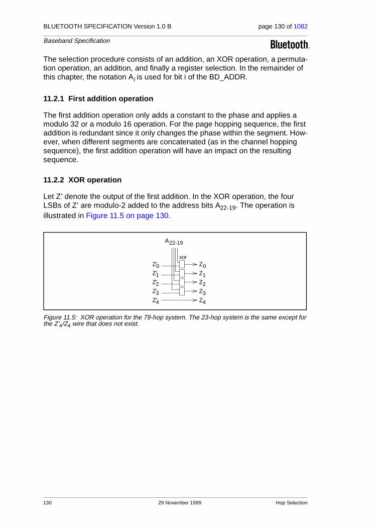
BLUETOOTH SPECIFICATION Version 1.0 B page 130 of 1082
Baseband Specification
The selection procedure consists of an addition, an XOR operation, a permuta-tion operation, an addition, and finally a register selection. In the remainder of this chapter, the notation Ai is used for bit i of the BD_ADDR.
11.2.1 First addition operation
The first addition operation only adds a constant to the phase and applies a modulo 32 or a modulo 16 operation. For the page hopping sequence, the first addition is redundant since it only changes the phase within the segment. How-ever, when different segments are concatenated (as in the channel hopping sequence), the first addition operation will have an impact on the resulting sequence.
11.2.2 XOR operation
Let Z’ denote the output of the first addition. In the XOR operation, the four LSBs of Z’ are modulo-2 added to the address bits A22-19. The operation is illustrated in Figure 11.5 on page 130.
Figure 11.5: XOR operation for the 79-hop system. The 23-hop system is the same except for the Z’4/Z4 wire that does not exist.
xor
A
Z'
Z'
Z'
Z'
Z'
22-19
0
1
2
3
4
Z
Z
Z
Z
Z
0
1
2
3
4
130 29 November 1999 Hop Selection

BLUETOOTH SPECIFICATION Version 1.0 B page 131 of 1082
Baseband Specification
11.2.3 Permutation operation
The permutation operation involves the switching from 5 inputs to 5 outputs for the 79 hop system and from 4 inputs to 4 outputs for 23 hop system, in a man-ner controlled by the control word. In Figure 11.6 on page 132 and Figure 11.7 on page 132 the permutation or switching box is shown. It consists of 7 stages of butterfly operations. Table 11.1 and Table 11.2 shows the control of the but-terflies by the control signals P. Note that P0-8 corresponds to D0-8, and,
corresponds to for in Figure 11.3 and Figure 11.4.
The Z input is the output of the XOR operation as described in the previous section. The butterfly operation can be implemented with multiplexers as depicted in Figure 11.8 on page 132.
Control signal Butterfly
Control signal Butterfly
P0 {Z0,Z1} P8 {Z1,Z4}
P1 {Z2,Z3} P9 {Z0,Z3}
P2 {Z1,Z2} P10 {Z2,Z4}
P3 {Z3,Z4} P11 {Z1,Z3}
P4 {Z0,Z4} P12 {Z0,Z3}
P5 {Z1,Z3} P13 {Z1,Z2}
P6 {Z0,Z2}
P7 {Z3,Z4}
Table 11.1: Control of the butterflies for the 79 hop system
Control signal Butterfly
Control signal Butterfly
P0 {Z0,Z1} P8 {Z0,Z2}
P1 {Z2,Z3} P9 {Z1,Z3}
P2 {Z0,Z3} P10 {Z0,Z3}
P3 {Z1,Z2} P11 {Z1,Z2}
P4 {Z0,Z2} P12 {Z0,Z1}
P5 {Z1,Z3} P13 {Z2,Z3}
P6 {Z0,Z1}
P7 {Z2,Z3}
Table 11.2: Control of the butterflies for the 23 hop system
Pi 9+
Ci Y1⊕ i 0…4=
Hop Selection 29 November 1999 131

BLUETOOTH SPECIFICATION Version 1.0 B page 132 of 1082
Baseband Specification
Figure 11.6: Permutation operation for the 79 hop system.
Figure 11.7: Permutation operation for the 23 hop system.
Figure 11.8: Butterfly implementation.
stage 1 2 3 4 5 6 7
13 12 11 10 9 8 7 6 45 23 01
0
1
2
3
4
Z
Z
Z
Z
Z
P P P P P P P P P P P P P P
stage 1 2 3 4 5 6 7
0
1
2
3
Z
Z
Z
Z
13 12 11 10 9 8 7 6 45 23 01P P P P P P P P P P P P P P
01
01
P
132 29 November 1999 Hop Selection

BLUETOOTH SPECIFICATION Version 1.0 B page 133 of 1082
Baseband Specification
11.2.4 Second addition operation
The addition operation only adds a constant to the output of the permutation operation. As a result, the 16-hop or 32-hop segment is mapped differently on the hop frequencies. The addition is applied modulo 79 or modulo 23 depend-ing on the system type (Europe/US vs. others).
11.2.5 Register bank
The output of the adder addresses a bank of 79 or 23 registers. The registers are loaded with the synthesizer code words corresponding to the hop frequen-cies 0 to 78 or 0 to 22. Note that the upper half of the bank contains the even hop frequencies, whereas the lower half of the bank contains the odd hop fre-quencies.
11.3 CONTROL WORD
In the following section Xj-i, i<j, will denote bits i, i+1,...,j of the bit vector X. By convention, X0 is the least significant bit of the vector X.
The control word P of the kernel is controlled by the overall control signals X, Y1, Y2, and A to F as illustrated in Figure 11.3 on page 129 and Figure 11.4 on page 129. During paging and inquiry, the inputs A to E use the address values as given in the corresponding columns of Table 11.3 on page 134 and Table 11.4 on page 134. In addition, the inputs X, Y1 and Y2 are used. The F input is unused. In the 79-hop system, the clock bits CLK6-2 (i.e., input X) specifies the phase within the length 32 sequence, while for the 23-hop system, CLK5-2 specifies the phase within the length 16 sequence. For both systems, CLK1 (i.e., inputs Y1 and Y2) is used to select between TX and RX. The address inputs determine the sequence order within segments. The final mapping onto the hop frequencies is determined by the register contents.
In the following we will distinguish between three types of clocks: the piconet’s master clock, the Bluetooth unit’s native clock, and the clock estimate of a paged Bluetooth unit. These types are marked in the following way:
1. CLK27-0: Master clock of the current piconet.
2. CLKN27-0: Native clock of the unit.
3. CLKE27-0: The paging unit’s estimate of the paged unit’s native clock.
During the CONNECTION state, the inputs A, C and D result from the address bits being bit-wise XORed with the clock bits as shown in the “Connection state” column of Table 11.3 on page 134 and Table 11.4 on page 134 (the two MSBs are XORed together, the two second MSBs are XORed together, etc.). Consequently, after every 32 (16) time slots, a new length 32 (16) segment is selected in the 79-hop (23-hop) system. The sequence order within a specific
Hop Selection 29 November 1999 133

BLUETOOTH SPECIFICATION Version 1.0 B page 134 of 1082
Baseband Specification
segment will not be repeated for a very long period. Thus, the overall hopping sequence consists of concatenated segments of 32-hops each. Since each 32-hop sequence spans more than 80% of the 79 MHz band, the desired fre-quency spreading over a short time interval is obtained.
Page scan/Inquiry scan Page/Inquiry
Page response (master/slave) and Inquiry response
Connection state
X
Y1 0
Y2 0
A
B
C
D
E
F 0 0 0
Table 11.3: Control for 79-hop system.
Page scan/Inquiry scan Page/Inquiry
Page response (master/slave) and Inquiry response
Connection state
X
Y1 0
Y2 0
A
B
C
D
E
F 0 0 0
Table 11.4: Control for 23-hop system.
CLKN16 12– Xp4 0–79( )
Xi4 0–79( )⁄ Xprm4 0–
79( )Xprs4 0–
79( )⁄ CLK6 2–
CLKE1 CLKN1⁄ CLKE1 CLKN1⁄ CLK1
32 CLKE1× ⁄
32 CLKN1×
32 CLKE1× ⁄
32 CLKN1×
32 CLK1×
A27 23– A27 23– A27 23– A27 23– CLK25 21–⊕
A22 19– A22 19– A22 19– A22 19–
A8 6 4 2 0, , , , A8 6 4 2 0, , , , A8 6 4 2 0, , , , A8 6 4 2 0, , , , CLK20 16–⊕
A18 10– A18 10– A18 10– A18 10– CLK15 7–⊕
A13 11 9 7 5 3 1, , , , , , A13 11 9 7 5 3 1, , , , , , A13 11 9 7 5 3 1, , , , , , A13 11 9 7 5 3 1, , , , , ,
16 CLK27 7–× mod 79
CLKN15 12– Xp3 0–23( )
Xi3 0–23( )⁄ Xprm3 0–
23( )Xprs3 0–
23( )⁄ CLK5 2–
CLKE1 CLKN1⁄ CLKE1 CLKN1⁄ CLK1
16 CLKE1× ⁄
16 CLKN1×
16 CLKE1× ⁄
16 CLKN1×
16 CLK1×
A27 23– A27 23– A27 23– A27 23– CLK25 21–⊕
A22 19– A22 19– A22 19– A22 19–
A8 6 4 2 0, , , , A8 6 4 2 0, , , , A8 6 4 2 0, , , , A8 6 4 2 0, , , , CLK20 16–⊕
A18 10– A18 10– A18 10– A18 10– CLK15 7–⊕
A13 11 9 7 5 3 1, , , , , , A13 11 9 7 5 3 1, , , , , , A13 11 9 7 5 3 1, , , , , , A13 11 9 7 5 3 1, , , , , ,
8 CLK27 6–× mod 23
134 29 November 1999 Hop Selection

BLUETOOTH SPECIFICATION Version 1.0 B page 135 of 1082
Baseband Specification
11.3.1 Page scan and Inquiry scan substates
In page scan, the Bluetooth device address of the scanning unit is used as address input. In inquiry scan, the GIAC LAP and the four LSBs of the DCI (as
), are used as address input for the hopping sequence. Naturally, for the transmitted access code and in the receiver correlator, the appropriate GIAC or DIAC is used. The application decides which inquiry access code to use depending on the purpose of the inquiry.
The five X input bits vary depending on the current state of the unit. In the page scan and inquiry scan substates, the native clock (CLKN) is used. In CON-NECTION state the master clock (CLK) is used as input. The situation is some-what more complicated for the other states.
11.3.2 Page substate
In the page substate of the 79-hop system, the paging unit shall start using the A-train, i.e., , where is the source’s estimate of the current receiver frequency in the paged unit. Clearly, the index k is a function of all the inputs in Figure 11.3. There are 32 possible paging frequen-cies within each 1.28 second interval. Half of these frequencies belongs to the A-train, the rest (i.e., ) belongs to the B-train. In order to achieve the -8 offset of the A-train, a constant of 24 can be added to the clock bits (which is equivalent to -8 due to the modulo 32 opera-tion). Clearly, the B-train may be accomplished by setting the offset to 8. A cyclic shift of the order within the trains is also necessary in order to avoid a possible repetitive mismatch between the paging and scanning units. Thus,
(EQ 2)
where
(EQ 3)
Alternatively, each switch between the A- and B-trains may be accomplished by adding 16 to the current value of (originally initialized with 24).
In the page substate of the 23-hop system, the paging unit makes use of the A-train only. A constant offset of 8 is used in order to start with . Moreover, only four bits are needed since the additions are modulo 16. Consequently,
(EQ 4)
A27 24–
f k 8–( ) … f k( ) … f k 7+( ), , , ,{ } f k( )
f k 8+( ) … f k 15+( ), , f, k 16–( ) … f k 9–( ), ,{ }
Xp79( )
CLKE16 12– koffset CLKE4 2– 0, CLKE16 12––( ) mod 16+ +[ ] mod 32,=
koffset24 A-train,
8 B-train.
=
koffset
f k 8–( )
Xp23( )
CLKE15 12– 8 CLKE+ 4 2– 0,+[ ] mod 16,=
Hop Selection 29 November 1999 135

BLUETOOTH SPECIFICATION Version 1.0 B page 136 of 1082
Baseband Specification
11.3.3 Page response
11.3.3.1 Slave response
A unit in the page scan substate recognizing its own access code enters the slave response substate. In order to eliminate the possibility of loosing the link due to discrepancies of the native clock CLKN and the master’s clock estimate CLKE, the four bits must be frozen at their current value. The value is frozen to the content it has in the slot where the recipient’s access code is detected. Note that the actual native clock is not stopped; it is merely the val-ues of the bits used for creating the X-input that are kept fixed for a while. In the sequel, a frozen value is marked by an asterisk (*).
For each response slot the paged unit will use an X-input value one larger (modulo 32 or 16) than in the preceding response slot. However, the first response is made with the X-input kept at the same value as it was when the access code was recognized. Let be a counter starting at zero. Then, the X-input in the -th response slot (the first response slot being the one imme-diately following the page slot now responding to) of the slave response sub-state becomes
(EQ 5)
and
(EQ 6)
for the 79-hop and 23-hop systems, respectively. The counter is set to zero in the slot where the slave acknowledges the page (see Figure 10.6 on page 105 and Figure 10.7 on page 105). Then, the value of is increased by one each time is set to zero, which corresponds to the start of a master TX slot. The X-input is constructed this way until the first accepted FHS packet is received and the immediately following response packet has been transmitted. After this the slave enters the CONNECTION state using the parameters received in the FHS packet.
11.3.3.2 Master response
The paging unit enters master response substate upon receiving a slave response. Clearly, also the master must freeze its estimated slave clock to the value that triggered a response from the paged unit. It is equivalent to using the values of the clock estimate when receiving the slave response (since only
will differ from the corresponding page transmission). Thus, the values are frozen when the slave ID packet is received. In addition to the used clock bits, also the current value of must be frozen. The master will adjust its X-input in the same way the paged unit does, i.e., by incrementing this value by
CLKN16 12–
N
N 1+( )
Xprs79( ) CLKN∗16 12– N+[ ] mod 32,=
Xprs23( )
CLKN∗15 12– N+[ ] mod 16,=
N
N
CLKN1
CLKE1
koffset
136 29 November 1999 Hop Selection

BLUETOOTH SPECIFICATION Version 1.0 B page 137 of 1082
Baseband Specification
one for each time is set to zero. The first increment shall be done before
sending the FHS packet to the paged unit. Let be a counter starting at one. The rules for forming the X-inputs become
(EQ 7)
and
(EQ 8)
for the 79-hop and 23-hop systems, respectively. The value of is increased each time is set to zero, which corresponds to the start of a master TX slot.
11.3.4 Inquiry substate
The X-input of the inquiry substate is quite similar to what is used in the page substate. Since no particular unit is addressed, the native clock CLKN of the inquirer is used. Moreover, which of the two train offsets to start with is of no real concern in this state. Consequently,
(EQ 9)
where is defined by (EQ 3). The initial choice of the offset is arbitrary. For the 23-hop system,
(EQ 10)
The GIAC LAP and the four LSBs of the DCI (as ) are used as address input for the hopping sequence generator.
11.3.5 Inquiry response
The inquiry response substate is similar to the slave response with respect to the X-input. Thus, (EQ 5) and (EQ 6) holds. However, the counter is increased not on basis, but rather after each FHS packet has been transmitted in response to the inquiry.
The GIAC LAP and the four LSBs of the DCI (as ) are used as address input for the hopping sequence generator. The other input bits to the generator are the same as in the case of page response.
CLKE1
N
Xprm79( )
CLKE[ ∗16 12– koffset∗ + +=
CLKE∗4 2– 0, CLKE∗16 12––( ) mod 16 N+ ] mod 32,
Xprm23( ) CLKE∗15 12– 8 CLKE∗4 2– 0, N+ + +[ ] mod 16,=
N
CLKE1
Xi79( ) CLKN16 12– koffset CLKN4 2– 0, CLKN16 12––( ) mod 16+ +[ ] mod 32,=
koffset
Xi23( )
CLKN15 12– 8 CLKN4 2– 0,+ +[ ] mod 16,=
A27 24–
N
CLKN1
A27 24–
Hop Selection 29 November 1999 137

BLUETOOTH SPECIFICATION Version 1.0 B page 138 of 1082
Baseband Specification
11.3.6 Connection state
In CONNECTION state, the clock bits to use in the channel hopping sequence generation are always according to the master clock, CLK. The address bits are taken from the Bluetooth device address of the master.
138 29 November 1999 Hop Selection

BLUETOOTH SPECIFICATION Version 1.0 B page 139 of 1082
Baseband Specification
12 BLUETOOTH AUDIO
On the Bluetooth air-interface, either a 64 kb/s log PCM format (A-law or µ-law) is used, or a 64 kb/s CVSD (Continuous Variable Slope Delta Modulation) is used. The latter format applies an adaptive delta modulation algorithm with syl-labic companding.
The voice coding on the line interface should have a quality equal to or better than the quality of 64 kb/s log PCM.
Table 12.1 on page 139 summarizes the voice coding schemes supported on the air interface. The appropriate voice coding scheme is selected after negoti-ations between the Link Managers.
12.1 LOG PCM CODEC
Since the voice channels on the air-interface can support a 64 kb/s information stream, a 64 kb/s log PCM traffic can be used for transmission. Either A-law or µ-law compression can be applied. In the event that the line interface uses A-law and the air interface uses µ-law or vice versa, a conversion from A-law to µ-law is performed. The compression method follows ITU-T recommendations G. 711.
12.2 CVSD CODEC
A more robust format for voice over the air interface is a delta modulation. This modulation scheme follows the waveform where the output bits indicate whether the prediction value is smaller or larger then the input waveform. To reduce slope overload effects, syllabic companding is applied: the step size is adapted according to the average signal slope. The input to the CVSD encoder is 64 ksamples/s linear PCM. Block diagrams of the CVSD encoder and CVSD decoder are shown in Figure 12.1 on page 140, Figure 12.2 on page 140 and Figure 12.3 on page 140. The system is clocked at 64 kHz.
Voice Codecs
linear CVSD
8-bit logarithmicA-law
µ-law
Table 12.1: Voice coding schemes supported on the air interface.
Bluetooth Audio 29 November 1999 139
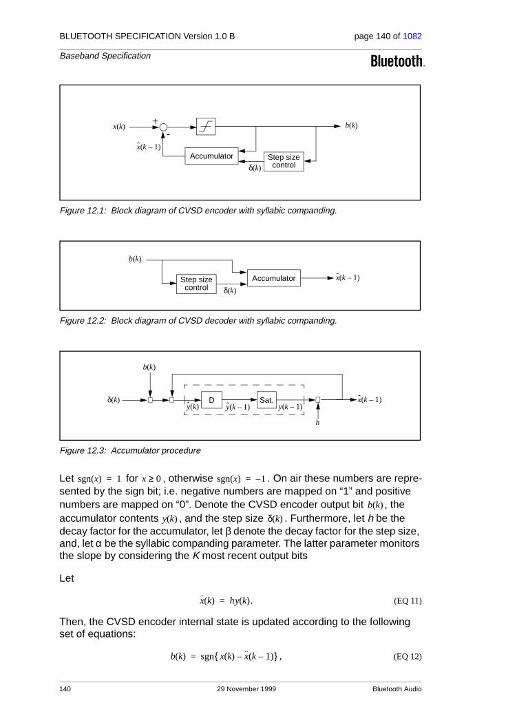
BLUETOOTH SPECIFICATION Version 1.0 B page 140 of 1082
Baseband Specification
Figure 12.1: Block diagram of CVSD encoder with syllabic companding.
Figure 12.2: Block diagram of CVSD decoder with syllabic companding.
Figure 12.3: Accumulator procedure
Let for , otherwise . On air these numbers are repre-sented by the sign bit; i.e. negative numbers are mapped on “1” and positive numbers are mapped on “0”. Denote the CVSD encoder output bit , the accumulator contents , and the step size . Furthermore, let h be the decay factor for the accumulator, let β denote the decay factor for the step size, and, let α be the syllabic companding parameter. The latter parameter monitors the slope by considering the K most recent output bits
Let
(EQ 11)
Then, the CVSD encoder internal state is updated according to the following set of equations:
(EQ 12)
Accumulator Step sizecontrol
b k( )
δ k( )
x k 1–( )
+-
x k( )
AccumulatorStep sizecontrol δ k( )
b k( )
x k 1–( )
D Sat.⊕⊗ ⊗
b k( )
δ k( )
h
y k( ) y k 1–( )y k 1–( )x k 1–( )
sgn x( ) 1= x 0≥ sgn x( ) 1–=
b k( )
y k( ) δ k( )
x k( ) hy k( ).=
b k( ) sgn x k( ) x k 1–( )–{ },=
140 29 November 1999 Bluetooth Audio
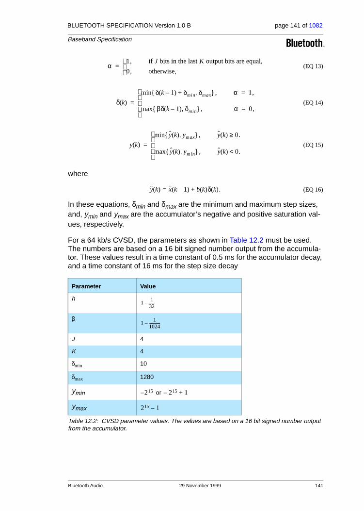
BLUETOOTH SPECIFICATION Version 1.0 B page 141 of 1082
Baseband Specification
(EQ 13)
(EQ 14)
(EQ 15)
where
(EQ 16)
In these equations, δmin and δmax are the minimum and maximum step sizes, and, ymin and ymax are the accumulator’s negative and positive saturation val-ues, respectively.
For a 64 kb/s CVSD, the parameters as shown in Table 12.2 must be used. The numbers are based on a 16 bit signed number output from the accumula-tor. These values result in a time constant of 0.5 ms for the accumulator decay, and a time constant of 16 ms for the step size decay
Parameter Value
h
β
J 4
K 4
δmin 10
δmax 1280
ymin or
ymax
Table 12.2: CVSD parameter values. The values are based on a 16 bit signed number output from the accumulator.
α1, if J bits in the last K output bits are equal,
0, otherwise,
=
δ k( )
δ k 1–( ) δmin+ δmax,{ },min α 1,=
βδ k 1–( ) δmin,{ }max , α 0,=
=
y k( )
y k( ) ymax,{ },min y k( ) 0.≥
y k( ) ymin,{ },max y k( ) 0.<
=
y k( ) x k 1–( ) b k( )δ k( )+= .
11
32------–
11
1024------------–
215– 215– 1+
215 1–
Bluetooth Audio 29 November 1999 141

BLUETOOTH SPECIFICATION Version 1.0 B page 142 of 1082
Baseband Specification
12.3 ERROR HANDLING
In the DV and HV3 packet, the voice is not protected by FEC. The quality of the voice in an error-prone environment then depends on the robustness of the voice coding scheme. CVSD, in particular, is rather insensitive to random bit errors, which are experienced as white background noise. However, when a packet is rejected because either the channel access code or the HEC test was unsuccessful, measures have to be taken to “fill” in the lost speech segment.
The voice payload in the HV2 packet is protected by a 2/3 rate FEC. If errors occur which cannot be corrected, these should be ignored. That is, from the 15-bit FEC segment with uncorrected errors, the 10-bit information part as found before the FEC decoder should be used. The HV1 packet is protected by a 3-repeat FEC. In the majority detection scheme uncorrected errors cannot occur.
12.4 GENERAL AUDIO REQUIREMENTS
These specifications are tentative and will be fixed within 18 months after the release of the Bluetooth Specification version 1.0 Draft Foundation.
12.4.1 Signal levels
For A-law and µ-law log-PCM encoded signals the requirements on signal lev-els follows ITU-T G.711.
Full swing at the 16 bit linear PCM interface to the CVSD encoder is defined to be 3 dBm0. A digital CVSD encoded test signal is provided in a Test Signal file available on the website. This signal is generated by a software implementa-tion of a reference CVSD encoder. The digital encoder input signal (1020 Hz, sine-wave) generating the test signal has a nominal power of -15 dBm0. When the CVSD encoded test signal is fed through the CVSD receiver chain, the nominal output power should be -15 ± 1.0 dBm0.
12.4.2 CVSD audio quality
For Bluetooth audio quality the requirements are put on the transmitter side. The 64 ksamples/s linear PCM input signal must have negligible spectral power density above 4 kHz. A set of reference input signals are encoded by the transmitter and sent through a reference decoder (available on the website). The power spectral density in the 4-32 kHz band of the decoded signal at the 64 ksample/s linear PCM output, should be more than 20 dB below the maxi-mum in the 0-4 kHz range.
142 29 November 1999 Bluetooth Audio

BLUETOOTH SPECIFICATION Version 1.0 B page 143 of 1082
Baseband Specification
13 BLUETOOTH ADDRESSING
13.1 BLUETOOTH DEVICE ADDRESS (BD_ADDR)
Each Bluetooth transceiver is allocated a unique 48-bit Bluetooth device address (BD_ADDR). This address is derived from the IEEE802 standard. This 48-bit address is divided into three fields:
• LAP field: lower address part consisting of 24 bits
• UAP field: upper address part consisting of 8 bits
• NAP field: non-significant address part consisting of 16 bits
The LAP and UAP form the significant part of the BD_ADDR. The total address space obtained is 232.
Figure 13.1: Format of BD_ADDR
13.2 ACCESS CODES
In the Bluetooth system, 72-bit and 68-bit access codes are used for signalling purposes. Three different access codes are defined, see also Section 4.2.1 on page 48:
• device access code (DAC)
• channel access code (CAC)
• inquiry access code (IAC)
There is one general IAC (GIAC) for general inquiry operations and there are 63 dedicated IACs (DIACs) for dedicated inquiry operations. All codes are derived from a LAP of the BD_ADDR. The device access code is used during page, page scan and page response substates. It is a code derived from the unit’s BD_ADDR. The channel access code characterizes the channel of the piconet and forms the preamble of all packets exchanged on the channel. The channel access code is derived from the LAP of the master BD_ADDR. Finally, the inquiry access code is used in inquiry operations. A general inquiry access code is common to all Bluetooth units; a set of dedicated inquiry access codes is used to inquire for classes of devices.
The access code is also used to indicate to the receiver the arrival of a packet. It is used for timing synchronization and offset compensation. The receiver cor-relates against the entire sync word in the access code, providing a very robust signalling. During channel setup, the code itself is used as an ID packet to sup-
UAP
8
LAP
24 16
NAP
LSB MSB
Bluetooth Addressing 29 November 1999 143

BLUETOOTH SPECIFICATION Version 1.0 B page 144 of 1082
Baseband Specification
port the acquisition process. In addition, it is used during random access proce-dures in the PARK state.
The access code consists of preamble, sync word and a trailer, see Section 4.2 on page 48. The next two sections describe the generation of the sync word.
13.2.1 Synchronization word definition
The sync words are based on a (64,30) expurgated block code with an overlay (bit-wise XOR) of an 64 bit full length PN-sequence. The expurgated code guarantees large Hamming distance ( ) between sync words based on different addresses. The PN sequence improves the autocorrelation properties of the access code. The following steps describe how to generate the sync word:
1. Generate information sequence;
2. XOR this with the “information covering” part of the PN overlay sequence;
3. Generate the codeword;
4. XOR the codeword with all 64 bits of the PN overlay sequence;
The information sequence is generated by appending 6 bits to the 24 bit LAP (step 1). The appended bits are if the MSB of the LAP equals 0. If the MSB of the LAP is 1 the appended bits are . The LAP MSB together with the appended bits constitute a length-seven Barker sequence. The purpose of including a Barker sequence is to further improve the autocorrelation proper-ties. In step 2 the information is pre-scrambled by XORing it with the bits
of the pseudo-random noise (PN) sequence (defined in section 13.2.2 on page 146). After generating the codeword (step 3), the complete PN sequence is XORed to the codeword (step 4). This step de-scrambles the infor-mation part of the codeword. At the same time the parity bits of the codeword are scrambled. Consequently, the original LAP and Barker sequence are ensured a role as a part of the access code sync word, and the cyclic proper-ties of the underlying code is removed. The principle is depicted in Figure 13.2 on page 145
In the sequel, binary sequences will be denoted by their corresponding D-transform (in which represents a delay of i time units). Let
be the 63 bit pseudo-random sequence, where
is the first bit (LSB) leaving the PRNG (see Figure 13.3 on page 147), and,
is the last bit (MSB). To obtain 64 bits, an extra zero is appended at the end
of this sequence (thus, is unchanged). For notational convenience, the reciprocal of this extended polynomial, , will be used in the sequel. This is the sequence in reverse order. We denote the 24 bit lower
dmin 14=
001101
110010
p34…p63
Di
p’ D( ) p’0 p’1D … p’62D62+ + +=
p’0p’62
p’ D( )
p D( ) D63p’ 1 D⁄( )=
p’ D( )
144 29 November 1999 Bluetooth Addressing
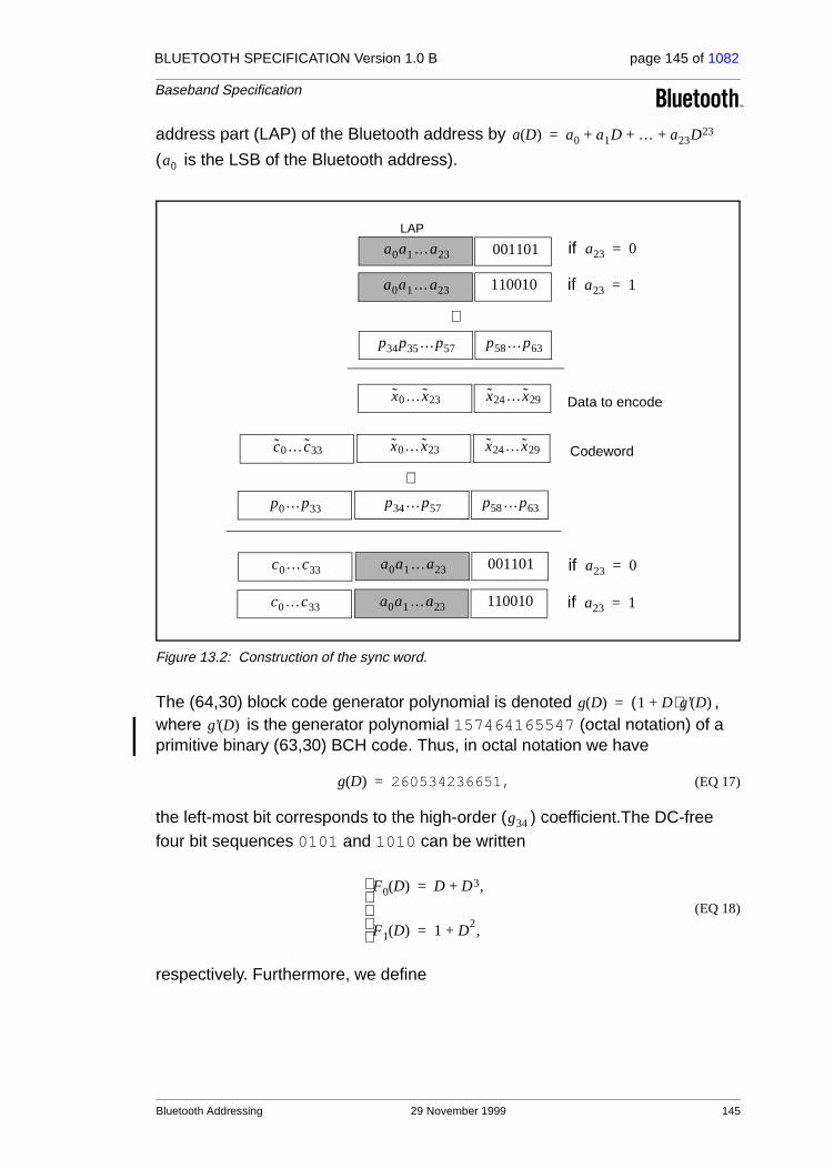
BLUETOOTH SPECIFICATION Version 1.0 B page 145 of 1082
Baseband Specification
address part (LAP) of the Bluetooth address by
( is the LSB of the Bluetooth address).
Figure 13.2: Construction of the sync word.
The (64,30) block code generator polynomial is denoted , where is the generator polynomial 157464165547 (octal notation) of a primitive binary (63,30) BCH code. Thus, in octal notation we have
(EQ 17)
the left-most bit corresponds to the high-order ( ) coefficient.The DC-free four bit sequences 0101 and 1010 can be written
(EQ 18)
respectively. Furthermore, we define
a D( ) a0 a1D … a23D23+ + +=
a0
a0a1…a23 001101
LAP
a0a1…a23 110010
if a23 0=
if a23 1=
p34p35…p57 p58…p63
⊕
x0…x23 x24…x29 Data to encode
x0… x23 x24…x29c0…c33 Codeword
p34…p57 p58…p63p0…p33
⊕
a0a1…a23 001101c0…c33 if a23 0=
a0a1…a23 110010c0…c33 if a23 1=
g D( ) 1 D+( )g’ D( )=
g’ D( )
g D( ) 260534236651,=
g34
F0 D( ) D D3,+=
F1 D( ) 1 D2,+=
Bluetooth Addressing 29 November 1999 145

BLUETOOTH SPECIFICATION Version 1.0 B page 146 of 1082
Baseband Specification
(EQ 19)
which are used to create the length seven Barker sequences. Then, the access code is generated by the following procedure:
1. Format the 30 information bits to encode:
2. Add the information covering part of the PN overlay sequence:
3. Generate parity bits of the (64,30) expurgated block code:1
4. Create the codeword:
5. Add the PN sequence:
6. Append the (DC-free) preamble and trailer:
13.2.2 Pseudo-random noise sequence generation
To generate the pseudo-random noise sequence we use the primitive polyno-mial . The LFSR and its starting state are shown in Figure 13.3 on page 147. The PN sequence generated (including the extra ter-minating zero) becomes (hexadecimal notation) 83848D96BBCC54FC. The LFSR output starts with the left-most bit of this PN sequence. This corresponds to of the previous section. Thus, using the reciprocal as overlay gives the 64 bit sequence
(EQ 20)
1. x(D) mod y(D) denotes the rest when x(D) is divided by y(D).
B0 D( ) D2 D3 D5,+ +=
B1 D( ) 1 D D4,+ +=
x D( ) a D( ) D24Ba23D( ).+=
x D( ) x D( ) p34 p35D … p63D29.+ + + +=
c D( ) D34x D( ) mod g D( )= .
s D( ) D34x D( ) c D( ).+=
s D( ) s D( ) p D( ).+=
y D( ) Fc0D( ) D4s D( ) D68Fa23
D( ).+ +=
h D( ) 1 D D3 D4 D6+ + + +=
p’ D( ) p D( )
p 3F2A33DD69B121C1,=
146 29 November 1999 Bluetooth Addressing

BLUETOOTH SPECIFICATION Version 1.0 B page 147 of 1082
Baseband Specification
where the left-most bit is (there are two initial zeros in the binary repre-
sentation of the hexadecimal digit 3), and is the right-most bit.
Figure 13.3: LFSR and the starting state to generate
13.2.3 Reserved addresses for GIAC and DIAC
There is a block of 64 contiguous LAPs reserved for Bluetooth inquiry opera-tions; one LAP common to all Bluetooth devices is reserved for general inquiry, the remaining 63 LAPs are reserved for dedicated inquiry of specific classes of Bluetooth devices. The same 64-block is used regardless of the contents of UAP and NAP. Consequently, none of these LAPs can be part of a user BD_ADDR.
When initializing HEC and CRC for the FHS packet of inquiry response, the UAP is replaced by DCI. Likewise, whenever one of the reserved BD_ADDRs is used for generating a frequency hop sequence, the UAP will be replaced by the DCI.
The reserved LAP addresses are tentatively chosen as 0x9E8B00-0x9E8B3F. The general inquiry LAP is tentatively chosen to 0x9E8B33. All addresses have the LSB at the rightmost position, hexadecimal notation.
13.3 ACTIVE MEMBER ADDRESS (AM_ADDR)
Each slave active in a piconet is assigned a 3-bit active member address (AM_ADDR). The all-zero AM_ADDR is reserved for broadcast messages. The master does not have an AM_ADDR. Its timing relative to the slaves distin-guishes it from the slaves. A slave only accepts a packet with a matching AM_ADDR and broadcast packets. The AM_ADDR is carried in the packet header. The AM_ADDR is only valid as long as a slave is active on the chan-nel. As soon as it is disconnected or parked, it loses the AM_ADDR.
The AM_ADDR is assigned by the master to the slave when the slave is acti-vated. This is either at connection establishment or when the slave is unparked. At connection establishment, the AM_ADDR is carried in the FHS payload (the FHS header itself carries the all-zero AM_ADDR). When unpark-ing, the AM_ADDR is carried in the unpark message.
p0 0=
p63 1=
+
1 0 0 0 0 0
+ +
p’ D( )
Bluetooth Addressing 29 November 1999 147

BLUETOOTH SPECIFICATION Version 1.0 B page 148 of 1082
Baseband Specification
13.4 PARKED MEMBER ADDRESS (PM_ADDR)
A slave in park mode can be identified by its BD_ADDR or by a dedicated parked member address (PM_ADDR). This latter address is a 8-bit member address that separates the parked slaves. The PM_ADDR is only valid as long as the slave is parked. When the slave is activated it is assigned an AM_ADDR but loses the PM_ADDR. The PM_ADDR is assigned to the slave the moment it is parked.
The all-zero PM_ADDR is reserved for parked slaves that only use their BD_ADDR to be unparked.
13.5 ACCESS REQUEST ADDRESS (AR_ADDR)
The access request address is used by the parked slave to determine the slave-to-master half slot in the access window it is allowed to send access request messages in, see also Section 10.8.4.6 on page 120. The AR_ADDR is assigned to the slave when it enters the park mode and is only valid as long as the slave is parked. The AR_ADDR is not necessarily unique; i.e. different parked slaves may have the same AR_ADDR.
148 29 November 1999 Bluetooth Addressing

BLUETOOTH SPECIFICATION Version 1.0 B page 149 of 1082
Baseband Specification
14 BLUETOOTH SECURITY
The Bluetooth technology provides peer-to-peer communications over short distances. In order to provide usage protection and information confidentiality, the system has to provide security measures both at the application layer and the link layer. These measures shall be appropriate for a peer environment. This means that in each Bluetooth unit, the authentication and encryption rou-tines are implemented in the same way. Four different entities are used for maintaining security at the link layer: a public address which is unique for each user1, two secret keys, and a random number which is different for each new transaction. The four entities and their sizes as used in Bluetooth are summa-rized in Table 14.1.
The Bluetooth device address (BD_ADDR) is the 48-bit IEEE address which is unique for each Bluetooth unit. The Bluetooth addresses are publicly known, and can be obtained via MMI interactions, or, automatically, via an inquiry rou-tine by a Bluetooth unit.
The secret keys are derived during initialization and are further never dis-closed. Normally, the encryption key is derived from the authentication key dur-ing the authentication process. For the authentication algorithm, the size of the key used is always 128 bits. For the encryption algorithm, the key size may vary between 1 and 16 octets (8 - 128 bits). The size of the encryption key shall be configurable for two reasons. The first has to do with the many different requirements imposed on cryptographic algorithms in different countries − both w.r.t. export regulations and official attitudes towards privacy in general. The second reason is to facilitate a future upgrade path for the security without the need of a costly redesign of the algorithms and encryption hardware; increas-ing the effective key size is the simplest way to combat increased computing power at the opponent side. Currently (1999) it seems that an encryption key size of 64 bits gives satisfying protection for most applications.
The encryption key is entirely different from the authentication key (even though the latter is used when creating the former, as is described in Section 14.5.4 on page 177). Each time encryption is activated, a new encryption key
1. The BD_ADDR is not a secured identity.
Entity Size
BD_ADDR 48 bits
Private user key, authentication 128 bits
Private user key, encryption
configurable length (byte-wise)
8-128 bits
RAND 128 bits
Table 14.1: Entities used in authentication and encryption procedures.
Bluetooth Security 29 November 1999 149

BLUETOOTH SPECIFICATION Version 1.0 B page 150 of 1082
Baseband Specification
shall be generated. Thus, the lifetime of the encryption key does not necessar-ily correspond to the lifetime of the authentication key.
It is anticipated that the authentication key will be more static in its nature than the encryption key − once established, the particular application running on the Bluetooth device decides when, or if, to change it. To underline the fundamen-tal importance of the authentication key to a specific Bluetooth link, it will often be referred to as the link key.
The RAND is a random number which can be derived from a random or pseudo-random process in the Bluetooth unit. This is not a static parameter, it will change frequently.
In the remainder of this chapter, the terms user and application will be used interchangeably to designate the entity that is at the originating or receiving side.
14.1 RANDOM NUMBER GENERATION
Each Bluetooth unit has a random number generator. Random numbers are used for many purposes within the security functions − for instance, for the challenge-response scheme, for generating authentication and encryption keys, etc. Ideally, a true random generator based on some physical process with inherent randomness is used. Examples of such processes are thermal noise from a semiconductor or resistor and the frequency instability of a free running oscillator. For practical reasons, a software based solution with a pseudo-random generator is probably preferable. In general, it is quite difficult to classify the randomness of a pseudo-random sequence. Within Bluetooth, the requirements placed on the random numbers used are that they be non-repeating and randomly generated.
The expression ‘non-repeating’ means that it shall be highly unlikely that the value should repeat itself within the lifetime of the authentication key. For example, a non-repeating value could be the output of a counter that is unlikely to repeat during the lifetime of the authentication key, or a date/time stamp.
The expression ‘randomly generated’ means that it shall not be possible to pre-dict its value with a chance that is significantly larger than 0 (e.g., greater than
for a key length of L bits).
Clearly, the LM can use such a generator for various purposes; i.e. whenever a random number is needed (such as the RANDs, the unit keys, Kinit, Kmaster, and random back-off or waiting intervals).
14.2 KEY MANAGEMENT
It is important that the encryption key size within a specific unit cannot be set by the user − this must be a factory preset entity. In order to prevent the user
1 2L⁄
150 29 November 1999 Bluetooth Security

BLUETOOTH SPECIFICATION Version 1.0 B page 151 of 1082
Baseband Specification
from over-riding the permitted key size, the Bluetooth baseband processing does not accept an encryption key given from higher software layers. When-ever a new encryption key is required, it must be created as defined in Section 14.5.4 on page 177.
Changing a link key should also be done through the defined baseband proce-dures. Depending on what kind of link key it is, different approaches are required. The details are found in Section 14.2.2.7 on page 157.
14.2.1 Key types
The link key is a 128-bit random number which is shared between two or more parties and is the base for all security transactions between these parties. The link key itself is used in the authentication routine. Moreover, the link key is used as one of the parameters when the encryption key is derived.
In the following, a session is defined as the time interval for which the unit is a member of a particular piconet. Thus, the session terminates when the unit dis-connects from the piconet.
The link keys are either semi-permanent or temporary. A semi-permanent link key is stored in non-volatile memory and may be used after the current session is terminated. Consequently, once a semi-permanent link key is defined, it may be used in the authentication of several subsequent connections between the Bluetooth units sharing it. The designation semi-permanent is justified by the possibility to change it. How to do this is described in Section 14.2.2.7 on page 157.
The lifetime of a temporary link key is limited by the lifetime of the current ses-sion − it cannot be reused in a later session. Typically, in a point-to-multipoint configuration where the same information is to be distributed securely to sev-eral recipients, a common encryption key is useful. To achieve this, a special link key (denoted master key) can temporarily replace the current link keys. The details of this procedure are found in Section 14.2.2.6 on page 157.
In the sequel we sometimes refer to what is denoted as the current link key. This is simply the link key in use at the current moment. It can be semi-permanent or temporary. Thus, the current link key is used for all authentica-tions and all generation of encryption keys in the on-going connection (ses-sion).
In order to accommodate for different types of applications, four types of link keys have been defined:
• the combination key KAB
• the unit key KA
• the temporary key Kmaster
• the initialization key Kinit
Bluetooth Security 29 November 1999 151

BLUETOOTH SPECIFICATION Version 1.0 B page 152 of 1082
Baseband Specification
In addition to these keys there is an encryption key, denoted Kc. This key is derived from the current link key. Whenever the encryption is activated by a LM command, the encryption key shall be changed automatically. The purpose of separating the authentication key and encryption key is to facilitate the use of a shorter encryption key without weakening the strength of the authentication procedure. There are no governmental restrictions on the strength of authenti-cation algorithms. However, in some countries, such restrictions exist on the strength of encryption algorithms.
For a Bluetooth unit, the combination key KAB and the unit key KA are function-ally indistinguishable; the difference is in the way they are generated. The unit key KA is generated in, and therefore dependent on, a single unit A. The unit key is generated once at installation of the Bluetooth unit; thereafter, it is very rarely changed. The combination key is derived from information in both units A and B, and is therefore always dependent on two units. The combination key is derived for each new combination of two Bluetooth units.
It depends on the application or the device whether a unit key or a combination key is used. Bluetooth units which have little memory to store keys, or, when installed in equipment that must be accessible to a large group of users, will preferably use their own unit key. In that case, they only have to store a single key. Applications that require a higher security level preferably use the combi-nation keys. These applications will require more memory since a combination key for each link to a different Bluetooth unit has to be stored.
The master key, Kmaster, is a link key only used during the current session. It will replace the original link key only temporarily. For example, this may be uti-lized when a master wants to reach more than two Bluetooth units simulta-neously using the same encryption key, see Section 14.2.2.6 on page 157.
The initialization key, Kinit, is used as link key during the initialization process when no combination or unit keys have been defined and exchanged yet or when a link key has been lost. The initialization key protects the transfer of ini-tialization parameters. The key is derived from a random number, an L-octet PIN code, and the BD_ADDR of the claimant unit. This key is only to be used during initialization.
The PIN can be a fixed number provided with the Bluetooth unit (for example when there is no MMI as in a PSTN plug). Alternatively, the PIN can be selected arbitrarily by the user, and then entered in both units that have to be matched. The latter procedure is used when both units have an MMI, for exam-ple a phone and a laptop. Entering a PIN in both units is more secure than using a fixed PIN in one of the units, and should be used whenever possible. Even if a fixed PIN is used, it shall be possible to change the PIN; this in order to prevent re-initialization by users who once got hold of the PIN. If no PIN is available, a default value of zero is to be used.
For many applications the PIN code will be a relatively short string of numbers. Typically, it may consist of only four decimal digits. Even though this gives suffi-
152 29 November 1999 Bluetooth Security

BLUETOOTH SPECIFICATION Version 1.0 B page 153 of 1082
Baseband Specification
cient security in many cases, there exist countless other, more sensitive, situa-tions where this is not reliable enough. Therefore, the PIN code can be chosen to be any length from 1 to 16 octets. For the longer lengths, we envision the units exchanging PIN codes not through mechanical (i.e. human) interaction, but rather through means supported by software at the application layer. For example, this can be a Diffie-Hellman key agreement, where the exchanged key is passed on to the generation process in both units, just as in the case of a shorter PIN code.
14.2.2 Key generation and initialization
The link keys have to be generated and distributed among the Bluetooth units in order to be used in the authentication procedure. Since the link keys must be secret, they cannot be obtained through an inquiry routine in the same way as the Bluetooth addresses. The exchange of the keys takes place during an ini-tialization phase which has to be carried out separately for each two units that want to implement authentication and encryption. All initialization procedures consist of the following five parts:
• generation of an initialization key
• authentication
• generation of link key
• link key exchange
• generating of encryption key in each unit
After the initialization procedure, the units can proceed to communicate, or the link can be disconnected. If encryption is implemented, the E0 algorithm is used with the proper encryption key derived from the current link key. For any new connection established between units A and B, they will use the common link key for authentication, instead of once more deriving Kinit from the PIN. A new encryption key derived from that particular link key will be created next time encryption is activated.
If no link key is available, the LM shall automatically start an initialization proce-dure.
14.2.2.1 Generation of initialization key,
A link key used temporarily during initialization is derived − the initialization key . This key is derived by the algorithm from the BD_ADDR of the claim-
ant unit, a PIN code, the length of the PIN (in octets), and a random number IN_RANDA issued (and created) by verifier. The principle is depicted in Figure
14.15 on page 177. The 128-bit output from will be used for key exchange during the generation of a link key. It is also used for authentication when two
Kinit
Kinit
Kinit E22
E22
Bluetooth Security 29 November 1999 153

BLUETOOTH SPECIFICATION Version 1.0 B page 154 of 1082
Baseband Specification
units have no record of a previous link key. When the units have performed the link key exchange, the initialization key shall be discarded.
When the initialization key is generated, the PIN is augmented with the BD_ADDR of the claimant unit. Since the maximum length of the PIN used in the algorithm cannot exceed 16 octets, it is possible that not all octets of BD_ADDR will be used. This procedure ensures that depends on the identity of the unit trying to connect to it (at least when short PIN codes are used). A fraudulent Bluetooth unit may try to test a large number of PINs by each time claiming another BD_ADDR. It is the application’s responsibility to take countermeasures against this threat. If the device address is kept fixed, the waiting interval until next try is permitted is increased exponentially (see Section 14.4.1 on page 170).
The details of the algorithm can be found in Section 14.5.3 on page 175.
14.2.2.2 Authentication
The authentication procedure is carried out as described in Section 14.4 on page 169. If the two units have not been in contact before, the initialization key Kinit is used as link key. Note that during each authentication, a new AU_RANDA is issued.
Mutual authentication is achieved by first performing the authentication proce-dure in one direction and, if successful, immediately followed by performing the authentication procedure in the opposite direction.
As a side effect of a successful authentication procedure an auxiliary parame-ter, the Authenticated Ciphering Offset (ACO), will be computed. The ACO is used for ciphering key generation as described in Section 14.2.2.5 on page 156. In case of mutual authentication, the ACO value from the second authen-tication is retained. However, in some situations an authentication event may be initiated simultaneously in both devices. When this happens, there is no way of telling which is the first and which is the second event. Then, both units shall use the ACO resulting from the challenge generated in the master unit.
The claimant/verifier status is determined by the LM.
14.2.2.3 Generation of a unit key
A unit key is generated when the Bluetooth unit is for the first time in opera-
tion; i.e. not during each initialization! The unit key is generated by the algorithm as described in Section 14.5.3 on page 175. Once created, the unit key is stored in non-volatile memory and (almost) never changed. If after initial-ization the unit key is changed, the previously initialized units will possess a wrong link key. At initialization, the application has to determine which of the
Kinit
E22
KA
E21
154 29 November 1999 Bluetooth Security

BLUETOOTH SPECIFICATION Version 1.0 B page 155 of 1082
Baseband Specification
two parties will provide the unit key as link key. Typically, this will be the unit with restricted memory capabilities, since this unit only has to remember its own unit key. The unit key is transferred to the other party and then stored as link key for that particular party. So, for example in Figure 14.1 on page 155, the unit key of unit A, , is being used as link key for the connection A-B; unit
A sends the unit key to unit B; unit B will store as the link key . For
another initialization, for example with unit C, unit A will reuse its unit key ,
whereas unit C stores it as .
Figure 14.1: Generation of unit key. When the unit key has been exchanged, the initialization key shall be discarded in both units.
14.2.2.4 Generation of a combination key
If it is desired to use a combination key, this key is first generated during the ini-tialization procedure. The combination key is the combination of two numbers generated in unit A and B, respectively. First, each unit generates a random number, say LK_RANDA and LK_RANDB. Then, utilizing with the random number and the own BD_ADDR, the two random numbers
(EQ 21)
and
(EQ 22)
are created in unit A and unit B, respectively. These numbers constitute the units’ contribution to the combination key that is to be created. Then, the two random numbers LK_RANDA and LK_RANDB are exchanged securely by
XOR:ing with the current link key, say . Thus, unit A sends to
unit B, while unit B sends to unit A. Clearly, if this is done dur-
ing the initialization phase the link key .
When the random numbers and have been mutually exchanged, each unit recalculates the other units contribution to the combina-tion key. This is possible since each unit knows the Bluetooth device address of the other unit. Thus, unit A calculates (EQ 22) and unit B calculates (EQ 21).
KA
KA KA KBA
KA
KCA
KA
UNIT BUNIT A
Kinit
K K = BA A
initK
E21
LK_KA E21 LK_RANDA BD_ADDRA,( ),=
LK_KB E21 LK_RANDB BD_ADDRB,( ),=
K K LK_RANDA⊕
K LK_RANDB⊕
K Kinit=
LK_RANDA LK_RANDB
Bluetooth Security 29 November 1999 155

BLUETOOTH SPECIFICATION Version 1.0 B page 156 of 1082
Baseband Specification
After this, both units combine the two numbers to generate the 128-bit link key. The combining operation is a simple bitwise modulo-2 addition (i.e. XOR). The result is stored in unit A as the link key and in unit B as the link key . When both units have derived the new combination key, a mutual authentica-tion procedure shall be initiated to confirm the success of the transaction. The old link key shall be discarded after a successful exchange of a new combina-tion key. The message flow between master and slave and the principle for cre-ating the combination key is depicted in Figure 14.2 on page 156.
Figure 14.2: Generating a combination key. The old link key (K) shall be discarded after the exchange of a new combination key has succeeded
14.2.2.5 Generating the encryption key
The encryption key, , is derived by algorithm from the current link key, a 96-bit Ciphering OFfset number (COF), and a 128-bit random number. The COF is determined in one of two ways. If the current link key is a master key, then COF is derived from the master BD_ADDR. Otherwise the value of COF is set to the value of ACO as computed during the authentication procedure. More precisely, we have1
(EQ 23)
There is an explicit call of when the LM activates encryption. Consequently, the encryption key is automatically changed each time the unit enters the
1. denotes the concatenation of the octet strings and .
KAB KBA
Unit B
LK_KA E21 LK_RANDA BD_ADDRA,( )=
CA
CA LK_RANDA K⊕=
Authentication
LK_KB E21 LK_RANDB BD_ADDRB,( )=
LK_KB E21 LK_RANDB BD_ADDRB,( )=
LK_RANDA CA K⊕=
CB LK_RANDB K⊕=
CB
LK_RANDB CB K⊕=
LK_KA E21 LK_RANDA BD_ADDRA,( )=
KAB LK_KA LK_KB⊕= KBA LK_KA LK_KB⊕ KAB= =
Unit A
KC E3
x y∪ x y
COF BD_ADDR BD_ADDR,∪ if link key is a master key
ACO, otherwise.
=
E3
156 29 November 1999 Bluetooth Security

BLUETOOTH SPECIFICATION Version 1.0 B page 157 of 1082
Baseband Specification
encryption mode. The details of the key generating function can be found in Section 14.5.4 on page 177.
14.2.2.6 Point-to-multipoint configuration
It is quite possible for the master to use separate encryption keys for each slave in a point-to-multipoint configuration with ciphering activated. Then, if the application requires more than one slave to listen to the same payload, each slave must be addressed individually. This may cause unwanted capacity loss for the piconet. Moreover, a Bluetooth unit (slave) is not capable of switching between two or more encryption keys in real time (e.g., after looking at the AM_ADDR in the header). Thus, the master cannot use different encryption keys for broadcast messages and individually addressed traffic. Alternatively, the master may tell several slave units to use a common link key (and, hence, indirectly also to use a common encryption key) and broadcast the information encrypted. For many applications, this key is only of temporary interest. In the sequel, this key is denoted .
The transfer of necessary parameters is protected by the routine described in Section 14.2.2.8 on page 158. After the confirmation of successful reception in each slave, the master shall issue a command to the slaves to replace their respective current link key by the new (temporary) master key. Before encryp-tion can be activated, the master also has to generate and distribute a common EN_RAND to all participating slaves. Using this random number and the newly derived master key, each slave generates a new encryption key.
Note that the master must negotiate what encryption key length to use individu-ally with each slave who wants to use the master key. Since the master has already negotiated at least once with each slave, it has some knowledge of what sizes can be accepted by the different slaves. Clearly, there might be situ-ations where the permitted key lengths of some units are incompatible. In that case, the master must have the limiting unit excluded from the group.
When all slaves have received the necessary data, the master can communi-cate information on the piconet securely using the encryption key derived from the new temporary link key. Clearly, each slave in possession of the master key can eavesdrop on all encrypted traffic, not only the traffic intended for itself. If so desired, the master can tell all participants to fall back to their old link keys simultaneously.
14.2.2.7 Modifying the link keys
In certain circumstances, it is desirable to be able to modify the link keys. A link key based on a unit key can be changed, but not very easily. The unit key is created once during the first use. Changing the unit key is a less desirable alternative, as several units may share the same unit key as link key (think of a printer whose unit key is distributed among all users using the printer’s unit key
E3
Kmaster
Bluetooth Security 29 November 1999 157
BLUETOOTH SPECIFICATION Version 1.0 B page 158 of 1082
Baseband Specification
as link key). Changing the unit key will require re-initialization of all units trying to connect. In certain cases, this might be desirable; for example to deny access to previously allowed units.
If the key change concerns combination keys, then the procedure is rather straightforward. The change procedure can be identical to the procedure illus-trated in Figure 14.2 on page 156, using the current value of the combination key as link key. This procedure can be carried out at any time after the authen-tication and encryption start. In fact, since the combination key corresponds to a single link, it can be modified each time this link is established. This will improve the security of the system since then old keys lose their validity after each session.
Of course, starting up an entirely new initialization procedure is also a possibil-ity. In that case, user interaction is necessary since a PIN is required in the authentication and encryption procedures.
14.2.2.8 Generating a master key
The key-change routines described so far are semi-permanent. To create the master link key, which can replace the current link key during an initiated ses-sion (see Section 14.2.2.6), other means are needed. First, the master creates a new link key from two 128-bit random numbers, RAND1 and RAND2. This is done by
(EQ 24)
Clearly, this key is a 128-bit random number. The reason to use the output of and not directly chose a random number as the key, is to avoid possible
problems with degraded randomness due to a poor implementation of the ran-dom number generator within the Bluetooth unit.
Then, a third random number, say RAND, is transmitted to the slave. Using with the current link key and RAND as inputs, both the master and slave com-putes a 128-bit overlay. The master sends the bitwise XOR of the overlay and the new link key to the slave. The slave, who knows the overlay, recalculates
. To confirm the success of this transaction, the units can perform an authentication procedure using the new link key (with the master as verifier and the slave as claimant). This procedure is then repeated for each slave who shall receive the new link key. The ACO values from the involved authentica-tions should not replace the current existing ACO as this ACO is needed to (re)compute a ciphering key when the master wants to fall back to the previous link (non-temporary) key.
When so required − and potentially long after the actual distribution of the mas-ter key − the master activates encryption by an LM command. Before doing that, the master must ensure that all slaves receive the same random number,
Kmaster E22 RAND1 RAND2 16, ,( ).=
E22
E22
Kmaster
158 29 November 1999 Bluetooth Security

BLUETOOTH SPECIFICATION Version 1.0 B page 159 of 1082
Baseband Specification
say EN_RAND, since the encryption key is derived through the means of individually in all participating units. Then, each slave computes a new encryp-tion key,
(EQ 25)
where the value of COF is derived from the master’s BD_ADDR as specified by equation (EQ 23). The details on the encryption key generating function can be found in Section 14.5.4 on page 177. The principle of the message flow between the master and slave when generating the master key is depicted in Figure 14.3. Note that in this case the ACO produced during the authentication is not used when computing the ciphering key.
Figure 14.3: Master link key distribution and computation of the corresponding encryption key.
14.3 ENCRYPTION
User information can be protected by encryption of the packet payload; the access code and the packet header are never encrypted. The encryption of the payloads is carried out with a stream cipher called E0 that is re-synchronized for every payload. The overall principle is shown in Figure 14.4 on page 160.
The stream cipher system E0 consists of three parts. One part performs the ini-tialization (generation of the payload key), the second part generates the key stream bits, and the third part performs the encryption and decryption. The payload key generator is very simple − it merely combines the input bits in an appropriate order and shift them into the four LFSRs used in the key stream generator. The main part of the cipher system is the second, as it also will be used for the initialization. The key stream bits are generated by a method derived from the summation stream cipher generator attributable to Massey and Rueppel. The method has been thoroughly investigated, and there exist good estimates of its strength with respect to presently known methods for cryptanalysis. Although the summation generator has weaknesses that can be
E3
KC E3 Kmaster EN_RAND, COF,( ),=
Master Slave
RAND
Kmaster E22 RAND1 RAND2, 16,( )=
OVL E22 K RAND, 16,( )= OVL E22 K RAND, 16,( )=C OVL Kmaster⊕=
Kmaster OVL C⊕=
C
Authentication
Bluetooth Security 29 November 1999 159
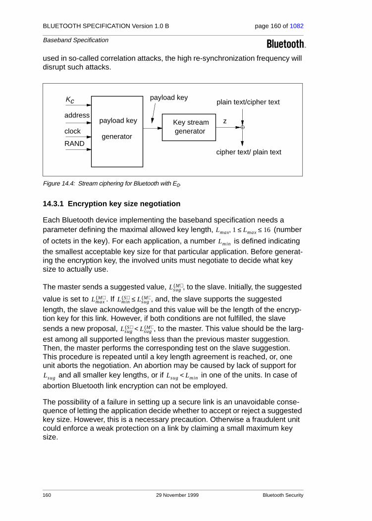
BLUETOOTH SPECIFICATION Version 1.0 B page 160 of 1082
Baseband Specification
used in so-called correlation attacks, the high re-synchronization frequency will disrupt such attacks.
Figure 14.4: Stream ciphering for Bluetooth with E0.
14.3.1 Encryption key size negotiation
Each Bluetooth device implementing the baseband specification needs a parameter defining the maximal allowed key length, (number
of octets in the key). For each application, a number is defined indicating the smallest acceptable key size for that particular application. Before generat-ing the encryption key, the involved units must negotiate to decide what key size to actually use.
The master sends a suggested value, , to the slave. Initially, the suggested
value is set to . If , and, the slave supports the suggested length, the slave acknowledges and this value will be the length of the encryp-tion key for this link. However, if both conditions are not fulfilled, the slave sends a new proposal, , to the master. This value should be the larg-est among all supported lengths less than the previous master suggestion. Then, the master performs the corresponding test on the slave suggestion. This procedure is repeated until a key length agreement is reached, or, one unit aborts the negotiation. An abortion may be caused by lack of support for
and all smaller key lengths, or if in one of the units. In case of abortion Bluetooth link encryption can not be employed.
The possibility of a failure in setting up a secure link is an unavoidable conse-quence of letting the application decide whether to accept or reject a suggested key size. However, this is a necessary precaution. Otherwise a fraudulent unit could enforce a weak protection on a link by claiming a small maximum key size.
generatorKey stream z
plain text/cipher text
cipher text/ plain text
address
generator
payload key
payload key
clock
Kc
RAND
Lmax 1 Lmax 16≤ ≤,
Lmin
LsugM( )
LmaxM( ) Lmin
S( ) LsugM( )≤
LsugS( ) Lsug
M( )<
Lsug Lsug Lmin<
160 29 November 1999 Bluetooth Security

BLUETOOTH SPECIFICATION Version 1.0 B page 161 of 1082
Baseband Specification
14.3.2 Encryption modes
If a slave has a semi-permanent link key (i.e. a combination key or a unit key), it can only accept encryption on slots individually addressed to itself (and, of course, in the reverse direction to the master). In particular, it will assume that broadcast messages are not encrypted. The possible traffic modes are described in Table 14.2. When an entry in the table refers to a link key, it means that the encryption/decryption engine uses the encryption key derived from that link key.
If the slave has received a master key, there are three possible combinations as defined in Table 14.3 on page 161. In this case, all units in the piconet uses a common link key, . Since the master uses encryption keys derived from this link key for all secure traffic on the piconet, it is possible to avoid ambiguity in the participating slaves on which encryption key to use. Also in this case the default mode is that broadcast messages are not encrypted. A specific LM-command is required to activate encryption − both for broadcast and for individually addressed traffic.
The master can issue an LM-command to the slaves telling them to fall back to their previous semi-permanent link key. Then, regardless of the previous mode they were in, they will end up in the first row of Table 14.2 on page 161; i.e. no encryption.
14.3.3 Encryption concept
For the encryption routine, a stream cipher algorithm will be used in which ciphering bits are bit-wise modulo-2 added to the data stream to be sent over the air interface. The payload is ciphered after the CRC bits are appended, but, prior to the FEC encoding.
Broadcast traffic Individually addressed traffic
No encryption No encryption
No encryption Encryption, Semi-permanent link key
Table 14.2: Possible traffic modes for a slave using a semi-permanent link key.
Broadcast traffic Individually addressed traffic
No encryption No encryption
No encryption Encryption,
Encryption, Encryption,
Table 14.3: Possible encryption modes for a slave in possession of a master key.
Kmaster
Kmaster
Kmaster Kmaster
Bluetooth Security 29 November 1999 161

BLUETOOTH SPECIFICATION Version 1.0 B page 162 of 1082
Baseband Specification
Each packet payload is ciphered separately. The cipher algorithm uses the master Bluetooth address, 26 bits of the master realtime clock (CLK 26-1) and
the encryption key as input, see Figure 14.5 on page 162 (where it is assumed that unit A is the master).
The encryption key KC is derived from the current link key, COF, and a random number, EN_RANDA (see Section 14.5.4 on page 177). The random number is issued by the master before entering encryption mode. Note that EN_RANDA is publicly known since it is transmitted as plain text over the air.
Within the algorithm, the encryption key is modified into another key
denoted . The maximum effective size of this key is factory preset and may be set to any multiple of eight between one and sixteen (8-128 bits). The procedure for deriving the key is described in Section 14.3.5 on page 165.
The real-time clock is incremented for each slot. The algorithm is re-initial-ized at the start of each new packet (i.e. for Master-to-Slave as well as for Slave-to-Master transmission). By using CLK26-1 at least one bit is changed between two transmissions. Thus, a new keystream is generated after each re-initialization. For packets covering more than a single slot, the Bluetooth clock as found in the first slot is being used for the entire packet.
The encryption algorithm generates a binary keystream, , which is modulo-2 added to the data to be encrypted. The cipher is symmetric; decryp-tion is performed in exactly the same way using the same key as used for encryption.
Figure 14.5: Functional description of the encryption procedure
E0
KC
E0 KC
K′C
E0
E0 Kcipher
dataB-A
dataA-B
Kcipher Kcipher
E0
E0
UNIT BUNIT A (master)
data
clockA
Kc
BD_ADDRA
clockA
BD_ADDRA
EN_RANDA
Kc
162 29 November 1999 Bluetooth Security

BLUETOOTH SPECIFICATION Version 1.0 B page 163 of 1082
Baseband Specification
14.3.4 Encryption algorithm
The system uses linear feedback shift registers (LFSRs) whose output is com-bined by a simple finite state machine (called the summation combiner) with 16 states. The output of this state machine is the key stream sequence, or, during initialization phase, the randomized initial start value. The algorithm is pre-sented with an encryption key , an 48-bit Bluetooth address, the master clock bits CLK26-1, and a 128-bit RAND value. Figure 14.6 on page 163 shows the setup.
There are four LFSRs (LFSR1,...,LFSR4) of lengths , , ,
and, , with feedback polynomials as specified in Table 14.4 on page 164. The total length of the registers is 128. These polynomials are all primi-tive. The Hamming weight of all the feedback polynomials is chosen to be five − a reasonable trade-off between reducing the number of required XOR gates in the hardware realization and obtaining good statistical properties of the gen-erated sequences.
Figure 14.6: Concept of the encryption engine.
KC
L1 25= L2 31= L3 33=
L4 39=
LFSR1
LFSR2
LFSR3
LFSR4
initi
al v
alue
s x1t
x2t
x3t
x4t
c0t
Encryption Stream Zt
Summation Combiner Logic
+
XOR
+ /2
21
3
2
2
3 2
T1
T2
blend
z-1
z-1
ct
ct+1
st+1
yt
XOR
2
2
x1t
x2t
x3t
x4t
Bluetooth Security 29 November 1999 163

BLUETOOTH SPECIFICATION Version 1.0 B page 164 of 1082
Baseband Specification
Let denote the symbol of LSFRi. From the four-tuple we derive
the value as
(EQ 26)
where the sum is over the integers. Thus can take the values 0,1,2,3, or 4. The output of the summation generator is now given by the following equations
(EQ 27)
(EQ 28)
(EQ 29)
where and are two different linear bijections over GF(4). Suppose
GF(4) is generated by the irreducible polynomial , and let be a zero of this polynomial in GF(4). The mappings and are now defined as
We can write the elements of GF(4) as binary vectors. This is summarized in Table 14.5.
Since the mappings are linear, we can realize them using XOR gates; i.e.
feedback weight
1 25 5
2 31 5
3 33 5
4 39 5
Table 14.4: The four primitive feedback polynomials.
i Li fi t( )
t25 t20 t12 t8 1+ + + +
t31 t24 t16 t12 1+ + + +
t33 t28 t24 t4 1+ + + +
t39 t36 t28 t4 1+ + + +
xti tth xt
1 … xt4, ,
yt
yt xti
i 1=
4
∑= ,
yt
zt xt1 xt
2 xt3 xt
4 ct0⊕ ⊕ ⊕ ⊕ 0 1,{ },∈=
st 1+ st 1+1 st 1+
0,( ) yt ct+
2-------------- 0 1 2 3, , ,{ },∈= =
ct 1+ ct 1+1 ct 1+
0,( ) st 1+ T1 ct[ ] T2 ct 1–[ ],⊕ ⊕= =
T1 .[ ] T2 .[ ]
x2 x 1+ + αT1 T2
T1: GF 4( ) GF 4( )→
x x|→
T2: GF 4( ) GF 4( )→
x α 1+( )x.|→
164 29 November 1999 Bluetooth Security
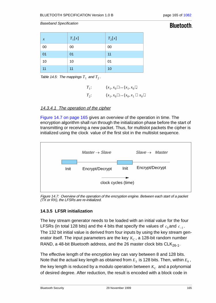
BLUETOOTH SPECIFICATION Version 1.0 B page 165 of 1082
Baseband Specification
14.3.4.1 The operation of the cipher
Figure 14.7 on page 165 gives an overview of the operation in time. The encryption algorithm shall run through the initialization phase before the start of transmitting or receiving a new packet. Thus, for multislot packets the cipher is initialized using the clock value of the first slot in the multislot sequence.
Figure 14.7: Overview of the operation of the encryption engine. Between each start of a packet (TX or RX), the LFSRs are re-initialized.
14.3.5 LFSR initialization
The key stream generator needs to be loaded with an initial value for the four LFSRs (in total 128 bits) and the 4 bits that specify the values of and . The 132 bit initial value is derived from four inputs by using the key stream gen-erator itself. The input parameters are the key , a 128-bit random number RAND, a 48-bit Bluetooth address, and the 26 master clock bits CLK26-1.
The effective length of the encryption key can vary between 8 and 128 bits. Note that the actual key length as obtained from is 128 bits. Then, within ,
the key length is reduced by a modulo operation between and a polynomial of desired degree. After reduction, the result is encoded with a block code in
00 00 00
01 01 11
10 10 01
11 11 10
Table 14.5: The mappings and .
x T1 x[ ] T2 x[ ]
T1 T2
T1: x1 x0,( ) x1 x0,( ),|→
T2: x1 x0,( ) x0 x1 x0⊕,( ).|→
clock cycles (time)
Init Encrypt/Decrypt Encrypt/DecryptInit
Master Slave Slave Master
c0 c 1–
KC
E3 E0
KC
Bluetooth Security 29 November 1999 165

BLUETOOTH SPECIFICATION Version 1.0 B page 166 of 1082
Baseband Specification
order to distribute the starting states more uniformly. The operation is defined in (EQ 30).
When the encryption key has been created the LFSRs are loaded with their ini-tial values. Then, 200 stream cipher bits are created by operating the genera-tor. Of these bits, the last 128 are fed back into the key stream generator as an initial value of the four LFSRs. The values of and are kept. From this point on, when clocked the generator produces the encryption (decryption) sequence which is bitwise XORed to the transmitted (received) payload data.
In the following, we will denote octet i of a binary sequence by the notation . We define bit 0 of to be the LSB. Then, the LSB of corresponds to
bit of the sequence , the MSB of is bit of . For instance, bit 24 of the Bluetooth address is the LSB of ADR[3].
The details of the initialization are as follows:
1. Create the encryption key to use from the 128-bit secret key and the 128-bit publicly known EN_RAND. Let , be the effective key length in number of octets. The resulting encryption key will be denoted :
(EQ 30)
where and . The polynomials are defined in Table 14.6.
2. Shift in the 3 inputs , the Bluetooth address, the clock, and the six-bit constant 111001 into the LFSRs. In total 208 bits are shifted in.
a) Open all switches shown in Figure 14.8 on page 168;
b) Arrange inputs bits as shown in Figure 14.8; Set the content of all shift register elements to zero. Set .
c) Start shifting bits into the LFSRs. The rightmost bit at each level of Figure 14.8 is the first bit to enter the corresponding LFSR.
d) When the first input bit at level i reaches the rightmost position of LFSRi, close the switch of this LFSR.
e) At (when the switch of LFSR4 is closed), reset both blend registers ; Up to this point, the content of and
has been of no concern. However, from this moment forward their content will be used in computing the output sequence.
f) From now on output symbols are generated. The remaining input bits are continuously shifted into their corresponding shift register. When the last bit has been shifted in, the shift register is clocked with input = 0;
Note: When finished, LFSR1 has effectively clocked 30 times with feedback closed, LFSR2 has clocked 24 times, LFSR3 has
ct ct 1–
X
X i[ ] X X i[ ]8i X X i[ ] 8i 7+ X
KCL 1 L 16≤ ≤,
K’C
K’C x( ) g2L( )
x( ) KC x( ) mod g1L( )
x( )( ),=
deg g1L( )
x( )( ) 8L= deg g2L( )
x( )( ) 128 8L–≤
K’C
t 0=
t 39=c39 c39 1– 0= = ct
ct 1–
166 29 November 1999 Bluetooth Security

BLUETOOTH SPECIFICATION Version 1.0 B page 167 of 1082
Baseband Specification
clocked 22 times, and LFSR4 has effectively clocked 16 times with feedback closed.
3. To mix initial data, continue to clock until 200 symbols have been produced with all switches closed ( );
4. Keep blend registers and , make a parallel load of the last 128 generated bits into the LFSRs according to Figure 14.9 at ;
After the parallel load in item 4, the blend register contents will be updated for each subsequent clock.
In Figure 14.8, all bits are shifted into the LFSRs, starting with the least signifi-cant bit (LSB). For instance, from the third octet of the address, ADR[2], first ADR16 is entered, followed by ADR17, etc. Furthermore, CL0 corresponds to CLK1,..., CL25 corresponds to CLK26.
Note that the output symbols are taken from the positions 24, 24, 32, and 32 for LFSR1, LFSR2,LFSR3, and LFSR4, respectively (counting the leftmost position as number 1).
deg deg
1 [8] 00000000 00000000 00000000 0000011d [119] 00e275a0 abd218d4 cf928b9b bf6cb08f
2 [16] 00000000 00000000 00000000 0001003f [112] 0001e3f6 3d7659b3 7f18c258 cff6efef
3 [24] 00000000 00000000 00000000 010000db [104] 000001be f66c6c3a b1030a5a 1919808b
4 [32] 00000000 00000000 00000001 000000af [96] 00000001 6ab89969 de17467f d3736ad9
5 [40] 00000000 00000000 00000100 00000039 [88] 00000000 01630632 91da50ec 55715247
6 [48] 00000000 00000000 00010000 00000291 [77] 00000000 00002c93 52aa6cc0 54468311
7 [56] 00000000 00000000 01000000 00000095 [71] 00000000 000000b3 f7fffce2 79f3a073
8 [64] 00000000 00000001 00000000 0000001b [63] 00000000 00000000 a1ab815b c7ec8025
9 [72] 00000000 00000100 00000000 00000609 [49] 00000000 00000000 0002c980 11d8b04d
10 [80] 00000000 00010000 00000000 00000215 [42] 00000000 00000000 0000058e 24f9a4bb
11 [88] 00000000 01000000 00000000 0000013b [35] 00000000 00000000 0000000c a76024d7
12 [96] 00000001 00000000 00000000 000000dd [28] 00000000 00000000 00000000 1c9c26b9
13 [104] 00000100 00000000 00000000 0000049d [21] 00000000 00000000 00000000 0026d9e3
14 [112] 00010000 00000000 00000000 0000014f [14] 00000000 00000000 00000000 00004377
15 [120] 01000000 00000000 00000000 000000e7 [7] 00000000 00000000 00000000 00000089
16 [128] 1 00000000 00000000 00000000 00000000 [0] 00000000 00000000 00000000 00000001
Table 14.6: Polynomials used when creating .
All polynomials are in hexadecimal notation. The LSB is in the rightmost position.
t 239=
ct ct 1–t 240=
L g1L( )
g2L( )
K’C
xti
i, 1 … 4, ,=
Bluetooth Security 29 November 1999 167

BLUETOOTH SPECIFICATION Version 1.0 B page 168 of 1082
Baseband Specification
Figure 14.8: Arranging the input to the LFSRs.
In Figure 14.9, the 128 binary output symbols Z0,..., Z127 are arranged in octets denoted Z[0],..., Z[15]. The LSB of Z[0] corresponds to the first of these sym-bols, the MSB of Z[15] is the latest output from the generator. These bits shall be loaded into the LFSRs according to the figure. It is a parallel load and no update of the blend registers is done. The first output symbol is generated at the same time. The octets are written into the registers with the LSB in the left-most position (i.e. the opposite of before). For example, Z24 is loaded into posi-tion 1 of LFSR4.
Figure 14.9: Distribution of the 128 last generated output symbols within the LFSRs.
14.3.6 Key stream sequence
When the initialization is finished, the output from the summation combiner is used for encryption/decryption. The first bit to use is the one produced at the parallel load, i.e. at . The circuit is run for the entire length of the current payload. Then, before the reverse direction is started, the entire initialization process is repeated with updated values on the input parameters.
= CLCL ...CL[0]
= CLCL ...CL[0]L
U
3 0
7 4
CL24
CL[0]L
CL25
UCL[0]
X 4
X
X
X 1
2
3
0 0 116 24
24
36
8 12 20
12
24
24
32
32
28
284
4
t
t
t
t
Kc'[0]Kc'[4]Kc'[8]Kc'[12]CL[1]ADR[2]
Kc'[1]Kc'[5]Kc'[9]Kc'[13]ADR[0]ADR[3]
Kc'[2]Kc'[6]Kc'[10]Kc'[14]CL[2]ADR[4]
Kc'[11]Kc'[7] Kc'[3] 1 1 1Kc'[15]ADR[1]ADR[5]
Z[3]
Xt
4
Xt
Xt
Xt
1
2
3
Z[4] Z[8]
Z[5]
Z[13]
Z[9]
Z[14]
Z[10]
Z[11]
Z[0]
Z[12]7-1
Z[6]
Z[7] Z[15]7-1
Z[2]
Z[1]
Z[12]0
Z[15]0
24
24
32
32
24
20128
12 16
4
4
24
28 36
28
t 240=
168 29 November 1999 Bluetooth Security

BLUETOOTH SPECIFICATION Version 1.0 B page 169 of 1082
Baseband Specification
Sample data of the encryption output sequence can be found in “Appendix IV” on page 899, Encryption Sample Data. A necessary, but not sufficient, condi-tion for all Bluetooth-compliant implementations is to produce these encryption streams for identical initialization values.
14.4 AUTHENTICATION
The entity authentication used in Bluetooth uses a challenge-response scheme in which a claimant’s knowledge of a secret key is checked through a 2-move protocol using symmetric secret keys. The latter implies that a correct claimant/verifier pair share the same secret key, for example K. In the challenge-response scheme the verifier challenges the claimant to authenticate a random input (the challenge), denoted by AU_RANDA, with an authentication code,
denoted by , and return the result SRES to the verifier, see Figure 14.10 on page 169. This figure shows also that in Bluetooth the input to E1 consists of the tuple AU_RANDA and the Bluetooth device address (BD_ADDR) of the
claimant. The use of this address prevents a simple reflection attack1. The secret K shared by units A and B is the current link key.
Figure 14.10: Challenge-response for the Bluetooth.
The challenge-response scheme for symmetric keys used in the Bluetooth is depicted in Figure 14.11 on page 170.
1. The reflection attack actually forms no threat in Bluetooth because all service requests are dealt with on a FIFO bases. When pre-emption is introduced, this attack is potentially dan-gerous.
E1
E1 E1
AU_RANDA
BD_ADDRB
Link key
AU_RANDA
BD_ADDRB
SRES’
AU_RANDA
SRES
?=
SRES
Verifier (Unit A) Claimant (Unit B)
Link key
SRES
ACO ACO
Bluetooth Security 29 November 1999 169

BLUETOOTH SPECIFICATION Version 1.0 B page 170 of 1082
Baseband Specification
Figure 14.11: Challenge-response for symmetric key systems.
In the Bluetooth, the verifier is not necessarily the master. The application indi-cates who has to be authenticated by whom. Certain applications only require a one-way authentication. However, in some peer-to-peer communications, one might prefer a mutual authentication in which each unit is subsequently the challenger (verifier) in two authentication procedures. The LM coordinates the indicated authentication preferences by the application to determine in which direction(s) the authentication(s) has to take place. For mutual authentication with the units of Figure 14.10 on page 169, after unit A has successfully authenticated unit B, unit B could authenticate unit A by sending a AU_RANDB (different from the AU_RANDA that unit A issued) to unit A, and deriving the SRES and SRES’ from the new AU_RANDB, the address of unit A, and the link key KAB.
If an authentication is successful the value of ACO as produced by should be retained.
14.4.1 Repeated attempts
When the authentication attempt fails, a certain waiting interval must pass before a new authentication attempt can be made. For each subsequent authentication failure with the same Bluetooth address, the waiting interval shall be increased exponentially. That is, after each failure, the waiting interval before a new attempt can be made, for example, twice as long as the waiting interval prior to the previous attempt1. The waiting interval shall be limited to a maximum. The maximum waiting interval depends on the implementation. The waiting time shall exponentially decrease to a minimum when no new failed attempts are being made during a certain time period. This procedure prevents an intruder to repeat the authentication procedure with a large number of differ-ent keys.
1. An other appropriate value larger than 1 may be used.
Verifier(User A)
Claimant(User B, with identity IDB)
RAND
SRESSRES E key IDB RAND, ,( )=
SRES’ E key IDB RAND, ,( )=
Check: SRES’ SRES=
E1
170 29 November 1999 Bluetooth Security

BLUETOOTH SPECIFICATION Version 1.0 B page 171 of 1082
Baseband Specification
To make the system somewhat less vulnerable to denial-of-service attacks, the Bluetooth units should keep a list of individual waiting intervals for each unit it has established contact with. Clearly, the size of this list must be restricted only to contain the N units with which the most recent contact has been made. The number N can vary for different units depending on available memory size and user environment.
14.5 THE AUTHENTICATION AND KEY-GENERATING FUNCTIONS
This section describes the algorithmic means for supporting the Bluetooth security requirements on authentication and key generation.
14.5.1 The authentication function E1
The authentication function proposed for the Bluetooth is a computationally
secure authentication code, or often called a MAC. uses the encryption
function called SAFER+. The algorithm is an enhanced version1 of an existing 64-bit block cipher SAFER-SK128, and it is freely available. In the sequel the block cipher will be denoted as the function which maps under a 128-bit key, a 128-bit input to a 128-bit output, i.e.
(EQ 31)
The details of are given in the next section. The function is constructed
using as follows
(EQ 32)
where , where is a keyed hash
function defined as2,
(EQ 33)
and where
1. It is presently one of the contenders for the Advanced Encryption Standard (AES) submitted by Cylink, Corp, Sunnyvale, USA
2. The operator +16 denotes bytewise addition mod 256 of the 16 octets, and the operator ⊕16 denotes bytewise XORing of the 16 octets.
E1
E1
Ar
Ar: 0 1,{ }1280 1,{ }128× 0 1,{ }128→
k x×( ) t.|→
Ar E1
Ar
E1: 0 1,{ }128 0 1,{ }128 0 1,{ }48×× 0 1,{ }32 0 1,{ }96×→
K RAND address, ,( ) SRES ACO,( ),|→
SRES Hash K RAND,address 6,,( ) 0 … 3, ,[ ]= Hash
Hash: 0 1,{ }1280 1,{ }128
0 1,{ }8 L×6 12,{ }××× 0 1,{ }128→
K I1 I2 L, , ,( ) A’r K[ ] E I2 L,( ) Ar K I1,( )⊕16
I1( )+16[ ],( ),|→
Bluetooth Security 29 November 1999 171

BLUETOOTH SPECIFICATION Version 1.0 B page 172 of 1082
Baseband Specification
(EQ 34)
is an expansion of the octet word into a 128-bit word. Thus we see that we
have to evaluate the function twice for each evaluation of . The key for
the second use of (actually ) is offseted from as follows1
(EQ 35)
A data flowchart of the computation of is depicted in Figure 14.12 on page
173. is also used to deliver the parameter ACO (Authenticated Ciphering
Offset) that is used in the generation of the ciphering key by , see equations (EQ 23) and (EQ 43). The value of ACO is formed by the octets 4 through 15 of the output of the hash function defined in (EQ 33), i.e.
. (EQ 36)
1. The constants are the first largest primes below 257 for which 10 is a primitive root.
E: 0 1,{ }8 L×6 12,{ }× 0 1,{ }8 16×→
X 0 … L, , 1–[ ] L,( ) X i(mod L)[ ] for i = 0...15( ),|→
L X
Ar E1 K
Ar A’r K
K 0[ ] K 0[ ] 233+( )= mod 256, K 1[ ] K 1[ ] 229,⊕=
K 2[ ] K 2[ ] 223+( )= mod 256, K 3[ ] K 3[ ] 193,⊕=
K 4[ ] K 4[ ] 179+( )= mod 256, K 5[ ] K 5[ ] 167,⊕=
K 6[ ] K 6[ ] 149+( )= mod 256, K 7[ ] K 7[ ] 131,⊕=
K 8[ ] K 8[ ] 233,⊕= K 9[ ] K 9[ ] 229+( )= mod 256,
K 10[ ] K 10[ ] 223,⊕= K 11[ ] K 11[ ] 193+( )= mod 256,
K 12[ ] K 12[ ] 179,⊕= K 13[ ] K 13[ ] 167+( )= mod 256,
K 14[ ] K 14[ ] 149,⊕= K 15[ ] K 15[ ] 131+( )= mod 256.
E1
E1
E3
ACO Hash K RAND,address 6,,( ) 4 … 15, ,[ ]=
172 29 November 1999 Bluetooth Security
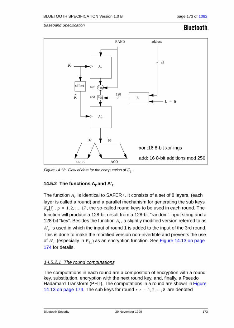
BLUETOOTH SPECIFICATION Version 1.0 B page 173 of 1082
Baseband Specification
Figure 14.12: Flow of data for the computation of .
14.5.2 The functions Ar and A’ r
The function is identical to SAFER+. It consists of a set of 8 layers, (each layer is called a round) and a parallel mechanism for generating the sub keys
, , the so-called round keys to be used in each round. The function will produce a 128-bit result from a 128-bit “random” input string and a 128-bit “key”. Besides the function , a slightly modified version referred to as
is used in which the input of round 1 is added to the input of the 3rd round. This is done to make the modified version non-invertible and prevents the use of (especially in ) as an encryption function. See Figure 14.13 on page 174 for details.
14.5.2.1 The round computations
The computations in each round are a composition of encryption with a round key, substitution, encryption with the next round key, and, finally, a Pseudo Hadamard Transform (PHT). The computations in a round are shown in Figure 14.13 on page 174. The sub keys for round are denoted
+16offset
RAND
E
32 96
SRES ACO
address
+16
xor
add
xor :16 8-bit xor-ings
add: 16 8-bit additions mod 256
Ar
A’r
K
K
48
128
L 6=
E1
Ar
Kp j[ ] p 1 2 … 17, , ,=
Ar
A′r
A′r E2x
r r, 1 2 … 8, , ,=
Bluetooth Security 29 November 1999 173

BLUETOOTH SPECIFICATION Version 1.0 B page 174 of 1082
Baseband Specification
, , . After the last round is applied in a similar fashion as all previous odd numbered keys.
14.5.2.2 The substitution boxes “e” and “l”
In Figure 14.13 on page 174 two boxes occur, marked “e” and “l”. These boxes implement the same substitutions as used in SAFER+; i.e. they implement
Their role, as in the SAFER+ algorithm, is to introduce non-linearity.
Figure 14.13: One round in and . The permuatation boxes show how input byte indices are mapped onto output byte indices. Thus, position 0 (leftmost) is mapped on position 8, position 1 is mapped on position 11, et cetera.
K2r 1– j[ ] K2r j[ ] j 0 1 … 15, , ,= k17 j[ ]
e l, : 0 … 255, ,{ } 0 … 255, ,{ },→
e : i 45 i (mod 257)( ) (mod 256),|→
l : i j s.t. i|→ e j( ).=
e e e e e e e e
PHT PHT PHT PHT PHT PHT
PHT PHT
PHT
PHT PHT
PHT
PHT PHT PHT PHT
PHT PHT PHT PHT PHT PHT PHT PHT
addition mod 256
bitwise XOR
PHT(x,y)= (2x+y mod 256, x+y mod 256)
2rK [0..15]
2r
l l l l l l l l
Only for A’r in round 3
A input[0..15]
128
128
PERMUTE: 8 11 12 15 2 1 6 5 10 9 14 13 0 7 4 3
PERMUTE: 8 11 12 15 2 1 6 5 10 9 14 13 0 7 4 3
PERMUTE: 8 11 12 15 2 1 6 5 10 9 14 13 0 7 4 3
PHT PHT PHT PHT PHT PHT PHT PHT
128 K [0..15]17
128
Only after last round
2r-1K [0..15]
RO
UN
D r,
r=
1,2,
...,8
60 1 2 3 4 5 7 8 9 10 11 12 13 14 15
2rK [15]K [0]
Ar A’r
174 29 November 1999 Bluetooth Security

BLUETOOTH SPECIFICATION Version 1.0 B page 175 of 1082
Baseband Specification
14.5.2.3 Key scheduling
In each round, 2 batches of 16 octet-wide keys are needed. These so-called round keys are derived as specified by the key scheduling in SAFER+. Figure 14.14 on page 175 gives an overview of how the round keys are deter-mined. The bias vectors B2, B3, ..., B17 are computed according to following equation:
(EQ 37)
Figure 14.14: Key scheduling in .
14.5.3 E2-Key generation function for authentication
The key used for authentication is derived through a procedure that is shown in Figure 14.15 on page 177. The figure shows two different modes of operation for the algorithm. In the first mode, the function should produce on input of a
128-bit RAND value and a 48-bit address, a 128-bit link key . This mode is utilized when creating unit keys and combination keys. In the second mode the function should produce, on input of a 128-bit RAND value and an octet
user PIN, a 128-bit link key . The second mode is used to create the initializa-tion key, and also whenever a master key is to be generated.
Kp j[ ]
Bp i[ ] 454517p i 1+ + mod 257( )
mod 257( ) mod 256( ), for i 0 … 15., ,= =
1
16
K
16
160 1 14
0 1514
0 1 1514
0 1 1514
0 1 1514
+
+
+15
1
...
bit-by-bitmodulo two
1,2,3,...,15,16
2,3,4,...,16,0
Select Bytes
16,0,1,...,13,14
16
16
160,1,2,...,14,15
16
B
B
B
2
3
17
K
K
2
3
17
K
Rotate each octet left by 3 bit positions
Rotate each octet left by 3 bit positions
Rotate each octet left by 3 bit positions
128 bit Key grouped in 16 octets
sum octets
Select octets
Select octets
Select octets
Ar
E2
K
E2 L
K
Bluetooth Security 29 November 1999 175

BLUETOOTH SPECIFICATION Version 1.0 B page 176 of 1082
Baseband Specification
When the initialization key is generated, the PIN is augmented with the BD_ADDR of the claimant unit. The augmentation always starts with the least significant octet of the address immediately following the most significant octet of the PIN. Since the maximum length of the PIN used in the algorithm cannot exceed 16 octets, it is possible that not all octets of BD_ADDR will be used.
This key generating algorithm again exploits the cryptographic function. For-mally can be expressed for mode 1 (denoted ) as
(EQ 38)
where (for mode 1)
(EQ 39)
Let be the number of octets in the user PIN. The augmenting is defined by
(EQ 40)
where it is assumed that unit B is the claimant. Then, in mode 2, (denoted
) can be expressed as
(EQ 41)
where
(EQ 42)
and is the number of octets in PIN’.
E2 E21
E21: 0 1,{ }128 0 1,{ }48× 0 1,{ }128→
RAND address,( ) A’r X Y,( )|→
X RAND 0…14[ ] RAND 15[ ] 6⊕( )∪=
Y address i (mod 6)[ ]
i 0=
15
∪=
L
PIN’PIN 0…L 1–[ ] BD_ADDRB 0… 5 15 L–,{ }min[ ],∪
PIN 0…L 1–[ ],
=L 16,<L 16,=
E2
E22
E22: 0 1,{ }8L’0 1,{ }128
1 2 … 16, , ,{ }×× 0 1,{ }128→
PIN’ RAND, L′,( ) A’r X Y,( )|→
X PIN’ i (mod L’)[ ]
i 0=
15
∪= ,
Y RAND 0…14[ ] RAND 15[ ] L’⊕( ),∪=
L’ min 16 L 6+,{ }=
176 29 November 1999 Bluetooth Security
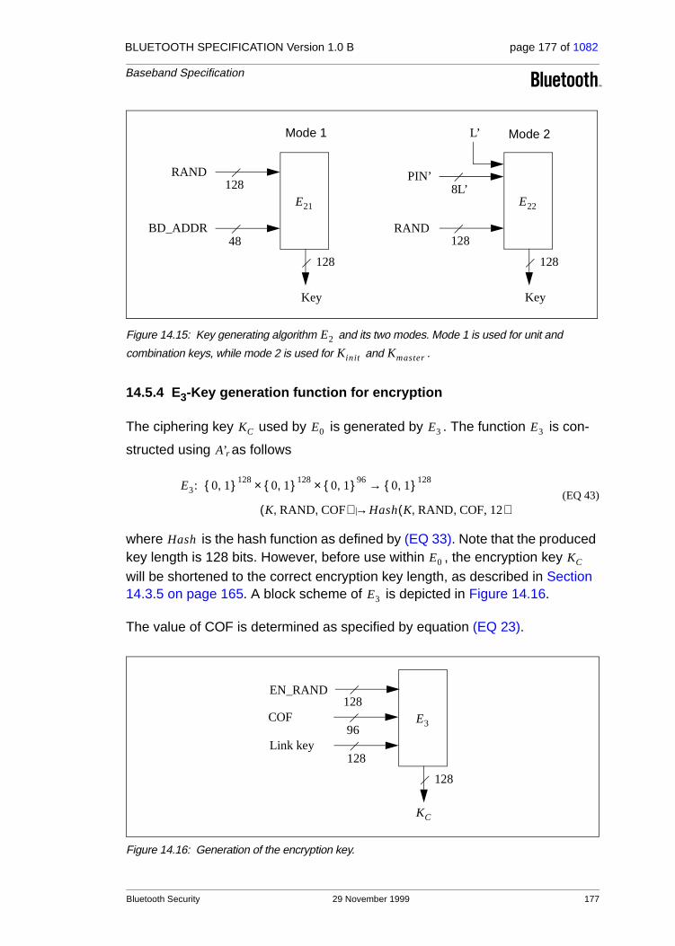
BLUETOOTH SPECIFICATION Version 1.0 B page 177 of 1082
Baseband Specification
Figure 14.15: Key generating algorithm and its two modes. Mode 1 is used for unit and
combination keys, while mode 2 is used for and .
14.5.4 E3-Key generation function for encryption
The ciphering key used by is generated by . The function is con-
structed using as follows
(EQ 43)
where is the hash function as defined by (EQ 33). Note that the produced key length is 128 bits. However, before use within , the encryption key will be shortened to the correct encryption key length, as described in Section 14.3.5 on page 165. A block scheme of is depicted in Figure 14.16.
The value of COF is determined as specified by equation (EQ 23).
Figure 14.16: Generation of the encryption key.
E22
RAND
PIN’
128
8L’
Key
128
E21
RAND
BD_ADDR
128
48
Key
128
Mode 1 Mode 2L’
E2
Kinit Kmaster
KC E0 E3 E3
A’r
E3: 0 1,{ }128 0 1,{ }128 0 1,{ }96×× 0 1,{ }128→
K RAND COF,,( ) Hash K RAND COF, 12, ,( )|→
Hash
E0 KC
E3
E3
EN_RAND128
128
128
96
KC
Link key
COF
Bluetooth Security 29 November 1999 177

BLUETOOTH SPECIFICATION Version 1.0 B page 178 of 1082
Baseband Specification
178 29 November 1999 Bluetooth Security

BLUETOOTH SPECIFICATION Version 1.0 B page 179 of 1082
Baseband Specification
15 LIST OF FIGURES
Figure 1.1: Different functional blocks in the Bluetooth system ...................41Figure 1.2: Piconets with a single slave operation (a), a multi-slave
operation (b) and a scatternet operation (c). .............................42
Figure 2.1: TDD and timing .........................................................................44Figure 2.2: Multi-slot packets ......................................................................44
Figure 4.1: Standard packet format. ............................................................47Figure 4.2: Access code format ...................................................................48Figure 4.3: Preamble ...................................................................................49Figure 4.4: Trailer in CAC when MSB of sync word is 0 (a), and when MSB
of sync word is 1 (b). .................................................................50Figure 4.5: Header format. ..........................................................................51Figure 4.6: Format of the FHS payload .......................................................56Figure 4.7: DV packet format ......................................................................59Figure 4.8: Payload header format for single-slot packets. .........................62Figure 4.9: Payload header format for multi-slot packets. ...........................62
Figure 5.1: Bit-repetition encoding scheme. ................................................67Figure 5.2: LFSR generating the (15,10) shortened Hamming code. .........68Figure 5.3: Receive protocol for determining the ARQN bit. .......................70Figure 5.4: Retransmit filtering for packets with CRC. ................................71Figure 5.5: Broadcast repetition scheme .....................................................73Figure 5.6: The LFSR circuit generating the HEC. ......................................74Figure 5.7: Initial state of the HEC generating circuit. .................................75Figure 5.8: HEC generation and checking. .................................................75Figure 5.9: The LFSR circuit generating the CRC. ......................................75Figure 5.10: Initial state of the CRC generating circuit. .................................76Figure 5.11: CRC generation and checking ..................................................76
Figure 7.1: Data whitening LFSR. ...............................................................79
Figure 8.1: Functional diagram of TX buffering. ..........................................81Figure 8.2: Functional diagram of RX buffering ...........................................84Figure 8.3: Header bit processes. ...............................................................86Figure 8.4: Payload bit processes. ..............................................................86
Figure 9.1: RX/TX cycle of Bluetooth master transceiver in normal mode for single-slot packets. ....................................................................88
Figure 9.2: RX/TX cycle of Bluetooth slave transceiver in normal mode for single-slot packets. ....................................................................88
Figure 9.3: RX timing of slave returning from hold state. ............................90
List of Figures 29 November 1999 179

BLUETOOTH SPECIFICATION Version 1.0 B page 180 of 1082
Baseband Specification
Figure 9.4: RX/TX cycle of Bluetooth transceiver in PAGE mode. ..............91Figure 9.5: Timing of FHS packet on successful page in first half slot. .......92Figure 9.6: Timing of FHS packet on successful page in second half slot. .92Figure 9.7: RX/TX timing in multi-slave configuration .................................93
Figure 10.1: Bluetooth clock. ........................................................................96Figure 10.2: Derivation of CLKE ...................................................................97Figure 10.3: Derivation of CLK in master (a) and in slave (b). ......................97Figure 10.4: State diagram of Bluetooth link controller. ................................98Figure 10.5: Conventional page (a), page while one SCO link present (b),
page while two SCO links present (c). ....................................103Figure 10.6: Messaging at initial connection when slave responds to first page
message. ................................................................................105Figure 10.7: Messaging at initial connection when slave responds to second
page message. .......................................................................105Figure 10.8: General beacon channel format ............................................. 117Figure 10.9: Definition of access window .................................................... 117Figure 10.10:Access procedure applying the polling technique. .................. 118Figure 10.11:Disturbance of access window by SCO traffic ........................ 118Figure 10.12:Extended sleep interval of parked slaves. .............................. 119
Figure 11.1: General block diagram of hop selection scheme. ...................128Figure 11.2: Hop selection scheme in CONNECTION state. ......................128Figure 11.3: Block diagram of hop selection kernel for the 79-hop system. 129Figure 11.4: Block diagram of hop selection kernel for the 23-hop system. 129Figure 11.5: XOR operation for the 79-hop system. The 23-hop system is the
same except for the Z’4/Z4 wire that does not exist. ..............130Figure 11.6: Permutation operation for the 79 hop system. ........................132Figure 11.7: Permutation operation for the 23 hop system. ........................132Figure 11.8: Butterfly implementation. ........................................................132
Figure 12.1: Block diagram of CVSD encoder with syllabic companding. ..140Figure 12.2: Block diagram of CVSD decoder with syllabic companding. ..140Figure 12.3: Accumulator procedure ...........................................................140
Figure 13.1: Format of BD_ADDR ..............................................................143Figure 13.2: Construction of the sync word. ...............................................145Figure 13.3: LFSR and the starting state to generate ................................147
Figure 14.1: Generation of unit key. When the unit key has been exchanged, the initialization key shall be discarded in both units. .............155
Figure 14.2: Generating a combination key. The old link key (K) shall be discarded after the exchange of a new combination key has succeeded ..............................................................................156
180 29 November 1999 List of Figures

BLUETOOTH SPECIFICATION Version 1.0 B page 181 of 1082
Baseband Specification
Figure 14.3: Master link key distribution and computation of the corresponding encryption key. ................................................159
Figure 14.4: Stream ciphering for Bluetooth with E0. ..................................160Figure 14.5: Functional description of the encryption procedure ................162Figure 14.6: Concept of the encryption engine. ..........................................163Figure 14.7: Overview of the operation of the encryption engine. Between
each start of a packet (TX or RX), the LFSRs arere-initialized. ............................................................................165
Figure 14.8: Arranging the input to the LFSRs. ...........................................168Figure 14.9: Distribution of the 128 last generated output symbols within the
LFSRs. ....................................................................................168Figure 14.10:Challenge-response for the Bluetooth. ....................................169Figure 14.11:Challenge-response for symmetric key systems. ....................170Figure 14.12:Flow of data for the computation of . ..................................173
Figure 14.13:One round in and . ...........................................................174
Figure 14.14:Key scheduling in . ..............................................................175
Figure 14.15:Key generating algorithm and its two modes. Mode 1 is used for unit and combination keys, while mode 2 is used for and .........................................................177
Figure 14.16:Generation of the encryption key. ...........................................177
E1
Ar A’r
Ar
E2
Kinit Kmaster
List of Figures 29 November 1999 181

BLUETOOTH SPECIFICATION Version 1.0 B page 182 of 1082
Baseband Specification
182 29 November 1999 List of Figures

BLUETOOTH SPECIFICATION Version 1.0 B page 183 of 1082
Baseband Specification
16 LIST OF TABLES
Table 2.1: Available RF channels ...............................................................43
Table 4.1: Summary of access code types. ................................................49Table 4.2: Packets defined for SCO and ACL link types.............................54Table 4.3: Description of the FHS payload .................................................56Table 4.4: Contents of SR field ...................................................................57Table 4.5: Contents of SP field ...................................................................57Table 4.6: Contents of page scan mode field..............................................58Table 4.7: Logical channel L_CH field contents.........................................63Table 4.8: Use of payload header flow bit on the logical channels. ............63Table 4.9: Link control packets ...................................................................65Table 4.10: ACL packets...............................................................................65Table 4.11: SCO packets ..............................................................................65
Table 10.1: Relationship between scan interval, train repetition, and paging modes R0, R1 and R2..............................................................101
Table 10.2: Relationship between train repetition, and paging modes R0, R1 and R2 when SCO links are present........................................103
Table 10.3: Initial messaging during start-up. .............................................104Table 10.4: Increase of train repetition when SCO links are present.......... 111Table 10.5: Messaging during inquiry routines. ..........................................112Table 10.6: Mandatory scan periods for P0, P1, P2 scan period modes. ...112
Table 11.1: Control of the butterflies for the 79 hop system .......................131Table 11.2: Control of the butterflies for the 23 hop system .......................131Table 11.3: Control for 79-hop system........................................................134Table 11.4: Control for 23-hop system........................................................134
Table 12.1: Voice coding schemes supported on the air interface..............139Table 12.2: CVSD parameter values. The values are based on a 16 bit
signed number output from the accumulator............................141
Table 14.1: Entities used in authentication and encryption procedures......149Table 14.2: Possible traffic modes for a slave using a semi-permanent link
key............................................................................................161Table 14.3: Possible encryption modes for a slave in possession of a master
key............................................................................................161Table 14.4: The four primitive feedback polynomials..................................164Table 14.5: The mappings and . ........................................................165T1 T2
List of Tables 29 November 1999 183

BLUETOOTH SPECIFICATION Version 1.0 B page 184 of 1082
Baseband Specification
Table 14.6: Polynomials used when creating . All polynomials are in hexadecimal notation. The LSB is in the rightmost position. ..........................................................167
Table 14.6: Polynomials used when creating . All polynomials are in hexadecimal notation. The LSB is in the rightmost position. ..........................................................167
184 29 November 1999 List of Tables

Part C
LINK MANAGER PROTOCOL
This specification describes the Link Manager Protocol (LMP) which is used for link set-up and control. The signals are interpreted and fil-tered out by the Link Manager on the receiving side and are not propagated to higher layers.

BLUETOOTH SPECIFICATION Version 1.0 B page 186 of 1082
Link Manager Protocol
186 29 November 1999

BLUETOOTH SPECIFICATION Version 1.0 B page 187 of 1082
Link Manager Protocol
CONTENTS
1 General ..............................................................................................191
2 Format of LMP ..................................................................................192
3 The Procedure Rules and PDUs .....................................................1933.1 General Response Messages..................................................1933.2 Authentication ..........................................................................194
3.2.1 Claimant has link key ..................................................194
3.2.2 Claimant has no link key .............................................194
3.2.3 Repeated attempts......................................................195
3.3 Pairing......................................................................................1953.3.1 Claimant accepts pairing .............................................195
3.3.2 Claimant requests to become verifier..........................195
3.3.3 Claimant rejects pairing...............................................196
3.3.4 Creation of the link key................................................196
3.3.5 Repeated attempts......................................................197
3.4 Change Link Key......................................................................1973.5 Change the Current Link Key...................................................198
3.5.1 Change to a temporary link key...................................198
3.5.2 Make the semi-permanent link key the current link key ........................................................................199
3.6 Encryption ................................................................................1993.6.1 Encryption mode .........................................................200
3.6.2 Encryption key size .....................................................200
3.6.3 Start encryption ...........................................................201
3.6.4 Stop encryption ...........................................................202
3.6.5 Change encryption mode, key or random number ......202
3.7 Clock Offset Request ...............................................................2023.8 Slot Offset Information .............................................................2033.9 Timing Accuracy Information Request .....................................2033.10 LMP Version.............................................................................2053.11 Supported Features .................................................................2053.12 Switch of Master-Slave Role....................................................2063.13 Name Request .........................................................................2073.14 Detach......................................................................................2073.15 Hold Mode................................................................................208
3.15.1 Master forces hold mode.............................................208
3.15.2 Slave forces hold mode...............................................208
3.15.3 Master or slave requests hold mode ...........................209
29 November 1999 187

BLUETOOTH SPECIFICATION Version 1.0 B page 188 of 1082
Link Manager Protocol
3.16 Sniff Mode................................................................................2093.16.1 Master forces a slave into sniff mode..........................210
3.16.2 Master or slave requests sniff mode ...........................210
3.16.3 Moving a slave from sniff mode to active mode .......... 211
3.17 Park Mode ............................................................................... 2113.17.1 Master forces a slave into park mode .........................213
3.17.2 Master requests slave to enter park mode..................213
3.17.3 Slave requests to be placed in park mode..................213
3.17.4 Master sets up broadcast scan window ......................214
3.17.5 Master modifies beacon parameters...........................214
3.17.6 Unparking slaves.........................................................214
3.18 Power Control ..........................................................................2153.19 Channel Quality-driven Change Between DM and DH............2173.20 Quality of Service (QoS) ..........................................................218
3.20.1 Master notifies slave of the quality of service..............218
3.20.2 Device requests new quality of service .......................219
3.21 SCO Links................................................................................2193.21.1 Master initiates an SCO link........................................220
3.21.2 Slave initiates an SCO link..........................................220
3.21.3 Master requests change of SCO parameters..............221
3.21.4 Slave requests change of SCO parameters................221
3.21.5 Remove an SCO link...................................................221
3.22 Control of Multi-slot Packets ....................................................2223.23 Paging Scheme .......................................................................223
3.23.1 Page mode..................................................................223
3.23.2 Page scan mode .........................................................223
3.24 Link Supervision ......................................................................224
4 Connection Establishment..............................................................225
5 Summary of PDUs............................................................................2265.1 Description of Parameters ......................................................231
5.1.1 Coding of features.......................................................234
5.1.2 List of error reasons ....................................................235
5.2 Default Values..........................................................................236
188 29 November 1999

BLUETOOTH SPECIFICATION Version 1.0 B page 189 of 1082
Link Manager Protocol
6 Test Modes........................................................................................2376.1 Activation and Deactivation of Test Mode ................................2376.2 Control of Test Mode................................................................2376.3 Summary of Test Mode PDUs..................................................238
7 Error Handling ..................................................................................239
8 List of Figures...................................................................................241
9 List of Tables ....................................................................................243
29 November 1999 189

BLUETOOTH SPECIFICATION Version 1.0 B page 190 of 1082
Link Manager Protocol
190 29 November 1999
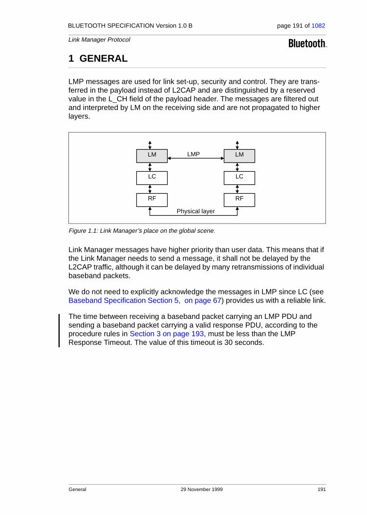
BLUETOOTH SPECIFICATION Version 1.0 B page 191 of 1082
Link Manager Protocol
1 GENERAL
LMP messages are used for link set-up, security and control. They are trans-ferred in the payload instead of L2CAP and are distinguished by a reserved value in the L_CH field of the payload header. The messages are filtered out and interpreted by LM on the receiving side and are not propagated to higher layers.
Figure 1.1: Link Manager’s place on the global scene.
Link Manager messages have higher priority than user data. This means that if the Link Manager needs to send a message, it shall not be delayed by the L2CAP traffic, although it can be delayed by many retransmissions of individual baseband packets.
We do not need to explicitly acknowledge the messages in LMP since LC (see Baseband Specification Section 5, on page 67) provides us with a reliable link.
The time between receiving a baseband packet carrying an LMP PDU and sending a baseband packet carrying a valid response PDU, according to the procedure rules in Section 3 on page 193, must be less than the LMP Response Timeout. The value of this timeout is 30 seconds.
LM
LC
RF
LM
LC
RF
LMP
Physical layer
General 29 November 1999 191

BLUETOOTH SPECIFICATION Version 1.0 B page 192 of 1082
Link Manager Protocol
2 FORMAT OF LMP
LM PDUs are always sent as single-slot packets and the payload header is therefore one byte. The two least significant bits in the payload header deter-mine the logical channel. For LM PDUs these bits are set.
The FLOW bit in the payload header is always one and is ignored on the receiving side. Each PDU is assigned a 7-bit opcode used to uniquely identify different types of PDUs, see Table 5.1 on page 226. The opcode and a one-bit transaction ID are positioned in the first byte of the payload body. The transac-tion ID is positioned in the LSB. It is 0 if the PDU belongs to a transaction initi-ated by the master and 1 if the PDU belongs to a transaction initiated by the slave. If the PDU contains one or more parameters these are placed in the pay-load starting at the second byte of the payload body. The number of bytes used depends on the length of the parameters. If an SCO link is present using HV1 packets and length of content is less than 9 bytes the PDUs can be transmitted in DV packets. Otherwise DM1 packets must be used. All parameters have lit-tle endian format, i.e. the least significant byte is transmitted first.
The source/destination of the PDUs is determined by the AM_ADDR in the packet header.
Figure 2.1: Payload body when LM PDUs are sent.
Each PDU is either mandatory or optional. The M/O field in the tables of Sec-tion 3 indicates this. The LM does not need to be able to transmit a PDU that is optional. The LM must recognize all optional PDUs that it receives and, if a response is required, send a valid response according to the procedure rules in Section 3. The reason that should be used in this case is unsupported LMP feature. If the optional PDU that is received does not require a response, no response is sent. Which of the optional PDUs a device supports can be requested, see Section 3.11 on page 205.
L_CH code Logical Channel Information
00 NA undefined
01 UA/I Continuing L2CAP message
10 UA/I Start L2CAP message
11 LM LMP message
Table 2.1: Logical channel L_CH field contents.
OpCode andtransaction Id
Content
LSB MSB
192 29 November 1999 Format of LMP

BLUETOOTH SPECIFICATION Version 1.0 B page 193 of 1082
Link Manager Protocol
3 THE PROCEDURE RULES AND PDUs
Each procedure is described and depicted with a sequence diagram. The fol-lowing symbols are used in the sequence diagrams:
Figure 3.1: Symbols used in sequence diagrams.
PDU1 is a PDU sent from A to B. PDU2 is a PDU sent from B to A. PDU3 is a PDU that is optionally sent from A to B. PDU4 is a PDU that is optionally sent from B to A. PDU5 is a PDU sent from either A or B. A vertical line indicates that more PDUs can optionally be sent.
3.1 GENERAL RESPONSE MESSAGES
The PDUs LMP_accepted and LMP_not_accepted are used as response mes-sages to other PDUs in a number of different procedures. The PDU LMP_accepted includes the opcode of the message that is accepted. The PDU LMP_not_accepted includes the opcode of the message that is not accepted and the reason why it is not accepted.
M/O PDU Contents
M LMP_accepted op code
M LMP_not_accepted op code
reason
Table 3.1: General response messages.
A B
PDU1
PDU2
PDU3
PDU4
PDU5
The Procedure Rules and PDUs 29 November 1999 193

BLUETOOTH SPECIFICATION Version 1.0 B page 194 of 1082
Link Manager Protocol
3.2 AUTHENTICATION
The authentication procedure is based on a challenge-response scheme as described in Baseband Specification Section 14.4, on page 169. The verifier sends an LMP_au_rand PDU which contains a random number (the challenge) to the claimant. The claimant calculates a response, which is a function of the challenge, the claimant’s BD_ADDR and a secret key. The response is sent back to the verifier, which checks if the response was correct or not. How the response should be calculated is described in Baseband Specification Section 14.5.1, on page 171. A successful calculation of the authentication response requires that two devices share a secret key. How this key is created is described in Section 3.3 on page 195. Both the master and the slave can be verifiers. The following PDUs are used in the authentication procedure:
3.2.1 Claimant has link key
If the claimant has a link key associated with the verifier, it calculates the response and sends it to the verifier with LMP_sres. The verifier checks the response. If the response is not correct, the verifier can end the connection by sending LMP_detach with the reason code authentication failure, see Section 3.14 on page 207.
Sequence 1: Authentication. Claimant has link key.
3.2.2 Claimant has no link key
If the claimant does not have a link key associated with the verifier it sends LMP_not_accepted with the reason code key missing after receiving LMP_au_rand.
Sequence 2: Authentication fails. Claimant has no link key.
M/O PDU Contents
M LMP_au_rand random number
M LMP_sres authentication response
Table 3.2: PDUs used for authentication.
verifierLM
claimantLM
LMP_au_randLMP_sres
verifierLM
claimantLM
LMP_au_randLMP_not_accepted
194 29 November 1999 The Procedure Rules and PDUs

BLUETOOTH SPECIFICATION Version 1.0 B page 195 of 1082
Link Manager Protocol
3.2.3 Repeated attempts
The scheme described in Baseband Specification Section 14.4.1, on page 170 shall be applied when an authentication fails. This will prevent an intruder from trying a large number of keys in a relatively short time.
3.3 PAIRING
When two devices do not have a common link key an initialization key (Kinit) is created based on a PIN and a random number. The Kinit is created when the verifier sends LMP_in_rand to the claimant. How the Kinit is calculated is described in Baseband Specification Section 14.5.3, on page 175. Authentica-tion then needs to be done, whereby the calculation of the authentication response is based on Kinit instead of the link key. After a successful authentica-tion, the link key is created. The PDUs used in the pairing procedure are:
3.3.1 Claimant accepts pairing
The verifier sends LMP_in_rand and the claimant replies with LMP_accepted. Both devices calculate Kinit, and an authentication (see Sequence 1) based on this key needs to be done. The verifier checks the authentication response and if correct, the link key is created; see Section 3.3.4 on page 196. If the authen-tication response is not correct the verifier can end the connection by sending LMP_detach with the reason code authentication failure.
Sequence 3: Claimant accepts pairing.
3.3.2 Claimant requests to become verifier
If the claimant has a fixed PIN it may request a switch of the claimant-verifier role in the pairing procedure by generating a new random number and send it
M/O PDU Contents
M LMP_in_rand random number
M LMP_au_rand random number
M LMP_sres authentication response
M LMP_comb_key random number
M LMP_unit_key key
Table 3.3: PDUs used for pairing.
VerifierLM
ClaimantLM
LMP_in_randLMP_accepted
The Procedure Rules and PDUs 29 November 1999 195
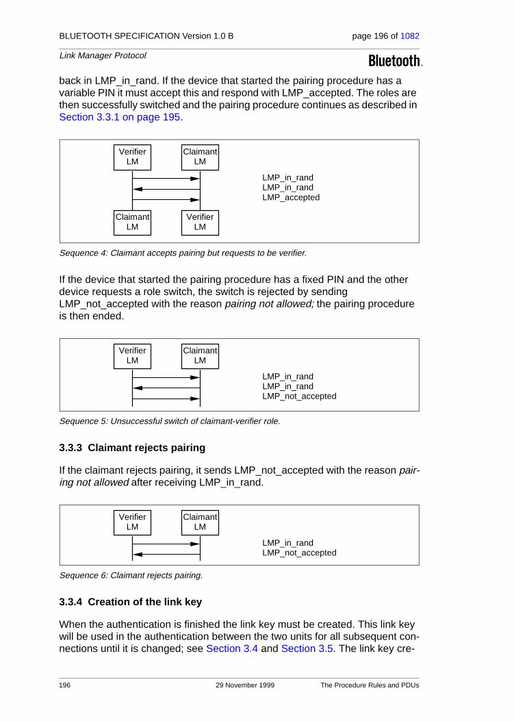
BLUETOOTH SPECIFICATION Version 1.0 B page 196 of 1082
Link Manager Protocol
back in LMP_in_rand. If the device that started the pairing procedure has a variable PIN it must accept this and respond with LMP_accepted. The roles are then successfully switched and the pairing procedure continues as described in Section 3.3.1 on page 195.
Sequence 4: Claimant accepts pairing but requests to be verifier.
If the device that started the pairing procedure has a fixed PIN and the other device requests a role switch, the switch is rejected by sending LMP_not_accepted with the reason pairing not allowed; the pairing procedure is then ended.
Sequence 5: Unsuccessful switch of claimant-verifier role.
3.3.3 Claimant rejects pairing
If the claimant rejects pairing, it sends LMP_not_accepted with the reason pair-ing not allowed after receiving LMP_in_rand.
Sequence 6: Claimant rejects pairing.
3.3.4 Creation of the link key
When the authentication is finished the link key must be created. This link key will be used in the authentication between the two units for all subsequent con-nections until it is changed; see Section 3.4 and Section 3.5. The link key cre-
VerifierLM
ClaimantLM
LMP_in_randLMP_in_randLMP_accepted
VerifierLM
ClaimantLM
VerifierLM
ClaimantLM
LMP_in_randLMP_in_randLMP_not_accepted
VerifierLM
ClaimantLM
LMP_in_randLMP_not_accepted
196 29 November 1999 The Procedure Rules and PDUs

BLUETOOTH SPECIFICATION Version 1.0 B page 197 of 1082
Link Manager Protocol
ated in the pairing procedure will either be a combination key or one of the unit’s unit keys. The following rules apply to the selection of the link key:
• if one unit sends LMP_unit_key and the other unit sends LMP_comb_key, the unit key will be the link key,
• if both units send LMP_unit_key, the master’s unit key will be the link key,
• if both units send LMP_comb_key, the link key is calculated as described in Baseband Specification Section 14.2.2, on page 153.
The content of LMP_unit_key is the unit key bitwise XORed with Kinit. The con-tent of LMP_comb_key is LK_RAND bitwise XORed with Kinit. Any device con-figured to use a combination key will store the link key in non-volatile memory.
Sequence 7: Creation of the link key.
3.3.5 Repeated attempts
When the authentication during pairing fails because of a wrong authentication response, the same scheme is applied as in Section 3.2.3 on page 195. This prevents an intruder from trying a large number of different PINs in a relatively short time.
3.4 CHANGE LINK KEY
If two devices are paired and the link key is derived from combination keys, the link key can be changed. If the link key is a unit key, the units must go through the pairing procedure in order to change the link key. The contents of the PDU is protected by a bitwise XOR with the current link key.
Sequence 8: Successful change of the link key.
M/O PDU Contents
M LMP_comb_key random number
M LMP_unit_key key
Table 3.4: PDUs used for change of link key.
VerifierLM
ClaimantLM
LMP_comb_key or LMP_unit_keyLMP_comb_key or LMP_unit_key
initiatingLM
LM
LMP_comb_keyLMP_comb_key
The Procedure Rules and PDUs 29 November 1999 197

BLUETOOTH SPECIFICATION Version 1.0 B page 198 of 1082
Link Manager Protocol
Sequence 9: Change of the link key not possible since the other unit uses a unit key.
If the change of link key is successful the new link key is stored in non-volatile memory, and the old link key is discarded. The new link key will be used as link key for all the following connections between the two devices until the link key is changed again. The new link key also becomes the current link key. It will remain the current link key until the link key is changed again, or until a tempo-rary link key is created, see Section 3.5 on page 198.
If encryption is used on the link and the current link key is a temporary link key, the procedure of changing link key must be immediately followed by a stop of the encryption by invoking the procedure in Section 3.6.4 on page 202. Encryp-tion can then be started again. This is to assure that encryption with encryption parameters known by other devices in the piconet is not used when the semi-permanent link key is the current link key.
3.5 CHANGE THE CURRENT LINK KEY
The current link key can be a semi-permanent link key or a temporary link key key. It can be changed temporarily, but the change is only valid for the session, see Baseband Specification Section 14.2.1, on page 151. Changing to a tem-porary link key is necessary if the piconet is to support encrypted broadcast.
3.5.1 Change to a temporary link key
In the following, we use the same terms as in Baseband Specification Section 14.2.2.8, on page 158. The master starts by creating the master key Kmaster as described in Baseband Specification (EQ 24), on page 158. Then the master issues a random number RAND and sends it to the slave in LMP_temp_rand. Both sides can then calculate an overlay denoted OVL as OVL= E22(current link key, RAND, 16). Then the master sends Kmaster protected by a modulo-2 addition with OVL to the slave in LMP_temp_key. The slave, who knows OVL,
M/O PDU Contents
M LMP_temp_rand random number
M LMP_temp_key key
M LMP_use_semi_permanent_key
-
Table 3.5: PDUs used to change the current link key.
initiatingLM
LM
LMP_comb_keyLMP_not_accepted
198 29 November 1999 The Procedure Rules and PDUs

BLUETOOTH SPECIFICATION Version 1.0 B page 199 of 1082
Link Manager Protocol
calculates Kmaster. After this, Kmaster becomes the current link key. It will be the current link key until a new temporary key is created or until the link key is changed, see Section 3.4 on page 197.
Sequence 10: Change to a temporary link key.
3.5.2 Make the semi-permanent link key the current link key
After the current link key has been changed to Kmaster, this change can be undone and the semi-permanent link key becomes the current link key again. If encryption is used on the link, the procedure of going back to the semi-perma-nent link key must be immediately followed by a stop of the encryption by invoking the procedure described in Section 3.6.4 on page 202. Encryption can then be started again. This is to assure that encryption with encryption parame-ters known by other devices in the piconet is not used when the semi-perma-nent link key is the current link key.
Sequence 11: Link key changed to the semi-permanent link key.
3.6 ENCRYPTION
If at least one authentication has been performed encryption may be used. If the master wants all slaves in the piconet to use the same encryption parame-ters it must issue a temporary key (Kmaster) and make this key the current link key for all slaves in the piconet before encryption is started, see Section 3.5 on page 198. This is necessary if broadcast packets should be encrypted.
M/O PDU Contents
O LMP_encryption_mode_req encryption mode
O LMP_encryption_key_size_req key size
O LMP_start_encryption_req random number
O LMP_stop_encryption_req -
Table 3.6: PDUs used for handling encryption.
MasterLM
SlaveLM
LMP_temp_randLMP_temp_key
MasterLM
SlaveLM
LMP_use_semi_permanent_keyLMP_accepted
The Procedure Rules and PDUs 29 November 1999 199

BLUETOOTH SPECIFICATION Version 1.0 B page 200 of 1082
Link Manager Protocol
3.6.1 Encryption mode
First of all the master and the slave must agree upon whether to use encryption or not and if encryption shall only apply to point-to-point packets or if encryption shall apply to both point-to-point packets and broadcast packets. If master and slave agree on the encryption mode, the master continues to give more detailed information about the encryption.
Sequence 12: Negotiation for encryption mode.
3.6.2 Encryption key size
The next step is to determine the size of the encryption key. In the following we use the same terms as in Baseband Specification Section 14.3.1, on page 160. The master sends LMP_encryption_key_size_req including the sug-gested key size Lsug, m, which is initially equal to Lmax, m. If Lmin, s ≤ Lsug, m and the slave supports Lsug, m it responds with LMP_accepted and Lsug, m will be used as the key size. If both conditions are not fulfilled the slave sends back LMP_encryption_key_size_req including the slave’s suggested key size Lsug, s. This value is the slave’s largest supported key size that is less than Lsug, m. Then the master performs the corresponding test on the slave’s suggestion. This procedure is repeated until a key size agreement is reached or it becomes clear that no such agreement can be reached. If an agreement is reached a unit sends LMP_accepted and the key size in the last LMP_encryption_key_size_req will be used. After this, the encryption is started; see Section 3.6.3 on page 201. If an agreement is not reached a unit sends LMP_not_accepted with the reason code Unsupported parameter value and the units are not allowed to communicate using Bluetooth link encryption.".
Sequence 13: Encryption key size negotiation successful.
initiatingLM LM
LMP_encryption_mode_reqLMP_accepted or LMP_not_accepted
masterLM
slaveLM
LMP_encryption_key_size_reqLMP_encryption_key_size_reqLMP_encryption_key_size_req
LMP_accepted
200 29 November 1999 The Procedure Rules and PDUs

BLUETOOTH SPECIFICATION Version 1.0 B page 201 of 1082
Link Manager Protocol
Sequence 14: Encryption key size negotiation failed.
3.6.3 Start encryption
Finally, encryption is started. The master issues the random number EN_RAND and calculates the encryption key as Kc=E3(current link key, EN_RAND, COF). See Baseband Specification Section 14.2.2.5, on page 156 and 14.2.2.2 for the definition of the COF. The random number must be the same for all slaves if the piconet should support encrypted broadcast. Then the master sends LMP_start_encryption_req, which includes EN_RAND. The slave calculates Kc when this message is received and acknowledges with LMP_accepted. On both sides, Kc and EN_RAND are used as input to the encryption algorithm Eo.
Sequence 15: Start of encryption.
Before starting encryption, higher-layer data traffic must be temporarily stopped to prevent reception of corrupt data. The start of encryption will be done in three steps:
1. Master is configured to transmit unencrypted packets, but to receive encrypted packets.
2. Slave is configured to transmit and receive encrypted packets.
3. Master is configured to transmit and receive encrypted packets.
Between step 1 and step 2, master-to-slave transmission is possible. This is when LMP_start_encryption_req is transmitted. Step 2 is triggered when the slave receives this message. Between step 2 and step 3, slave-to-master transmission is possible. This is when LMP_accepted is transmitted. Step 3 is triggered when the master receives this message.
masterLM
slaveLM
LMP_encryption_key_size_reqLMP_encryption_key_size_reqLMP_encryption_key_size_req
LMP_not_accepted
MasterLM
SlaveLM
LMP_start_encryption_reqLMP_accepted
The Procedure Rules and PDUs 29 November 1999 201

BLUETOOTH SPECIFICATION Version 1.0 B page 202 of 1082
Link Manager Protocol
3.6.4 Stop encryption
Sequence 16: Stop of encryption.
Before stopping encryption, higher-layer data traffic must be temporarily stopped to prevent reception of corrupt data. Stopping of encryption is then done in three steps, similar to the procedure for starting encryption.
1. Master is configured to transmit encrypted packets, but to receive unen-crypted packets.
2. Slave is configured to transmit and receive unencrypted packets.
3. Master is configured to transmit and receive unencrypted packets.
Between step 1 and step 2 master to slave transmission is possible. This is when LMP_stop_encryption_req is transmitted. Step 2 is triggered when the slave receives this message. Between step 2 and step 3 slave to master trans-mission is possible. This is when LMP_accepted is transmitted. Step 3 is trig-gered when the master receives this message.
3.6.5 Change encryption mode, key or random number
If the encryption mode, encryption key or encryption random number need to be changed, encryption must first be stopped and then re-started with the new parameters.
3.7 CLOCK OFFSET REQUEST
When a slave receives the FHS packet, the difference is computed between its own clock and the master’s clock included in the payload of the FHS packet. The clock offset is also updated each time a packet is received from the mas-ter. The master can request this clock offset anytime during the connection. By saving this clock offset the master knows on what RF channel the slave wakes up to PAGE SCAN after it has left the piconet. This can be used to speed up the paging time the next time the same device is paged.
M/O PDU Contents
M LMP_clkoffset_req -
M LMP_clkoffset_res clock offset
Table 3.7: PDUs used for clock offset request.
MasterLM
SlaveLM
LMP_stop_encryption_reqLMP_accepted
202 29 November 1999 The Procedure Rules and PDUs
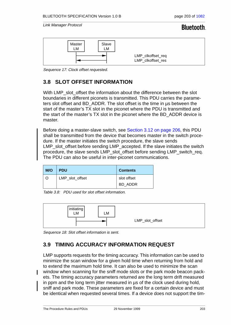
BLUETOOTH SPECIFICATION Version 1.0 B page 203 of 1082
Link Manager Protocol
Sequence 17: Clock offset requested.
3.8 SLOT OFFSET INFORMATION
With LMP_slot_offset the information about the difference between the slot boundaries in different piconets is transmitted. This PDU carries the parame-ters slot offset and BD_ADDR. The slot offset is the time in µs between the start of the master’s TX slot in the piconet where the PDU is transmitted and the start of the master’s TX slot in the piconet where the BD_ADDR device is master.
Before doing a master-slave switch, see Section 3.12 on page 206, this PDU shall be transmitted from the device that becomes master in the switch proce-dure. If the master initiates the switch procedure, the slave sends LMP_slot_offset before sending LMP_accepted. If the slave initiates the switch procedure, the slave sends LMP_slot_offset before sending LMP_switch_req. The PDU can also be useful in inter-piconet communications.
Sequence 18: Slot offset information is sent.
3.9 TIMING ACCURACY INFORMATION REQUEST
LMP supports requests for the timing accuracy. This information can be used to minimize the scan window for a given hold time when returning from hold and to extend the maximum hold time. It can also be used to minimize the scan window when scanning for the sniff mode slots or the park mode beacon pack-ets. The timing accuracy parameters returned are the long term drift measured in ppm and the long term jitter measured in µs of the clock used during hold, sniff and park mode. These parameters are fixed for a certain device and must be identical when requested several times. If a device does not support the tim-
M/O PDU Contents
O LMP_slot_offset slot offset
BD_ADDR
Table 3.8: PDU used for slot offset information.
MasterLM
SlaveLM
LMP_clkoffset_reqLMP_clkoffset_res
initiatingLM LM
LMP_slot_offset
The Procedure Rules and PDUs 29 November 1999 203

BLUETOOTH SPECIFICATION Version 1.0 B page 204 of 1082
Link Manager Protocol
ing accuracy information it sends LMP_not_accepted with the reason code unsupported LMP feature when the request is received. The requesting device must in this case assume worst case values (drift=250ppm and jitter=10µs).
Sequence 19: The requested device supports timing accuracy information.
Sequence 20: The requested device does not support timing accuracy information.
M/O PDU Contents
O LMP_timing_accuracy_req -
O LMP_timing_accuracy_res drift
jitter
Table 3.9: PDUs used for requesting timing accuracy information.
initiatingLM
LM
LMP_timing_accuracy_reqLMP_timing_accuracy_res
initiatingLM
LM
LMP_timing_accuracy_reqLMP_not_accepted
204 29 November 1999 The Procedure Rules and PDUs

BLUETOOTH SPECIFICATION Version 1.0 B page 205 of 1082
Link Manager Protocol
3.10 LMP VERSION
LMP supports requests for the version of the LM protocol. The requested device will send a response with three parameters: VersNr, CompId and Sub-VersNr. VersNr specifies the version of the Bluetooth LMP specification that the device supports. CompId is used to track possible problems with the lower Bluetooth layers. All companies that create a unique implementation of the Link Manager shall have their own CompId. The same company is also responsible for the administration and maintenance of the SubVersNr. It is recommended that each company has a unique SubVersNr for each RF/BB/LM implementa-tion. For a given VersNr and CompId, the values of the SubVersNr must increase each time a new implementation is released. For both CompId and SubVersNr the value 0xFFFF means that no valid number applies. There is no ability to negotiate the version of the LMP. The sequence below is only used to exchange the parameters.
Sequence 21: Request for LMP version.
3.11 SUPPORTED FEATURES
The Bluetooth radio and link controller may support only a subset of the packet types and features described in Baseband Specification and Radio Specifica-tion. The PDU LMP_features_req and LMP_features_res are used to exchange this information. A device may not send any packets other than ID, FHS, NULL, POLL, DM1 or DH1 before it is aware of the supported features of the other device. After the features request has been carried out, the intersec-tion of the supported packet types for both sides may also be transmitted. Whenever a request is issued, it must be compatible with the supported fea-tures of the other device. For instance, when establishing an SCO link the initi-ator may not propose to use HV3 packets if that packet type is not supported by the other device. Exceptions to this rule are LMP switch reg and LMP slot offset, which can be sent as the first LMP messages when two Bluetooth
M/O PDU Contents
M LMP_version_req VersNrCompIdSubVersNr
M LMP_version_res VersNrCompIdSubVersNr
Table 3.10: PDUs used for LMP version request.
initiatingLM
LM
LMP_version_reqLMP_version_res
The Procedure Rules and PDUs 29 November 1999 205

BLUETOOTH SPECIFICATION Version 1.0 B page 206 of 1082
Link Manager Protocol
devices have been connected and before the requesting side is aware of the other side’s features (switch is an optional feature).
Sequence 22: Request for supported features.
3.12 SWITCH OF MASTER-SLAVE ROLE
Since the paging device always becomes the master of the piconet, a switch of the master-slave role is sometimes needed, see Baseband Specification Sec-tion 10.9.3, on page 123. Suppose device A is slave and device B is master. The device that initiates the switch finalizes the transmission of the current L2CAP message and then sends LMP_switch_req.
If the switch is accepted, the other device finalizes the transmission of the cur-rent L2CAP message and then responds with LMP_accepted. After this, the procedure described from the 2nd bullet in Baseband Specification Section 10.9.3, on page 123 is carried out.
If the switch is rejected, the other device responds with LMP_not_accepted and no switch is performed.
Sequence 23: Master-slave switch accepted.
M/O PDU Contents
M LMP_features_req features
M LMP_features_res features
Table 3.11: PDUs used for features request.
M/O PDU Contents
O LMP_switch_req -
Table 3.12: PDU used for master slave switch.
initiatingLM
LM
LMP_features_reqLMP_features_res
initiatingLM
LM
LMP_switch_reqLMP_accepted
206 29 November 1999 The Procedure Rules and PDUs

BLUETOOTH SPECIFICATION Version 1.0 B page 207 of 1082
Link Manager Protocol
Sequence 24: Master-slave switch not accepted.
3.13 NAME REQUEST
LMP supports name request to another Bluetooth device. The name is a user-friendly name associated with the Bluetooth device and consists of a maximum of 248 bytes coded according to the UTF-8 standard. The name is fragmented over one or more DM1 packets. When the LMP_name_req is sent, a name off-set indicates which fragment is expected. The corresponding LMP_name_res carries the same name offset, the name length indicating the total number of bytes in the name of the Bluetooth device and the name fragment, where:• name fragment(N) = name(N + name offset), if (N + name offset) < name length• name fragment(N) = 0 ,otherwise.Here 0 ≤ N ≤ 13. In the first sent LMP_name_req, name offset=0. Sequence 25 is then repeated until the initiator has collected all fragments of the name.
Sequence 25: Device’s name requested and it responses.
3.14 DETACH
The connection between two Bluetooth devices can be closed anytime by the master or the slave. A reason parameter is included in the message to inform the other party of why the connection is closed.
M/O PDU Contents
M LMP_name_req name offset
M LMP_name_res name offsetname lengthname fragment
Table 3.13: PDUs used for name request.
M/O PDU Contents
M LMP_detach reason
Table 3.14: PDU used for detach.
initiatingLM
LM
LMP_switch_reqLMP_not_accepted
initiatingLM
LM
LMP_name_reqLMP_name_res
The Procedure Rules and PDUs 29 November 1999 207

BLUETOOTH SPECIFICATION Version 1.0 B page 208 of 1082
Link Manager Protocol
Sequence 26: Connection closed by sending LMP_detach.
3.15 HOLD MODE
The ACL link of a connection between two Bluetooth devices can be placed in hold mode for a specified hold time. During this time no ACL packets will be transmitted from the master. The hold mode is typically entered when there is no need to send data for a relatively long time. The transceiver can then be turned off in order to save power. But the hold mode can also be used if a device wants to discover or be discovered by other Bluetooth devices, or wants to join other piconets. What a device actually does during the hold time is not controlled by the hold message, but it is up to each device to decide.
3.15.1 Master forces hold mode
The master can force hold mode if there has previously been a request for hold mode that has been accepted. The hold time included in the PDU when the master forces hold mode cannot be longer than any hold time the slave has previously accepted when there was a request for hold mode.
Sequence 27: Master forces slave into hold mode.
3.15.2 Slave forces hold mode
The slave can force hold mode if there has previously been a request for hold mode that has been accepted. The hold time included in the PDU when the slave forces hold mode cannot be longer than any hold time the master has previously accepted when there was a request for hold mode.
M/O PDU Contents
O LMP_hold hold time
O LMP_hold_req hold time
Table 3.15: PDUs used for hold mode.
initiatingLM
LM
LMP_detach
MasterLM
SlaveLM
LMP_hold
208 29 November 1999 The Procedure Rules and PDUs
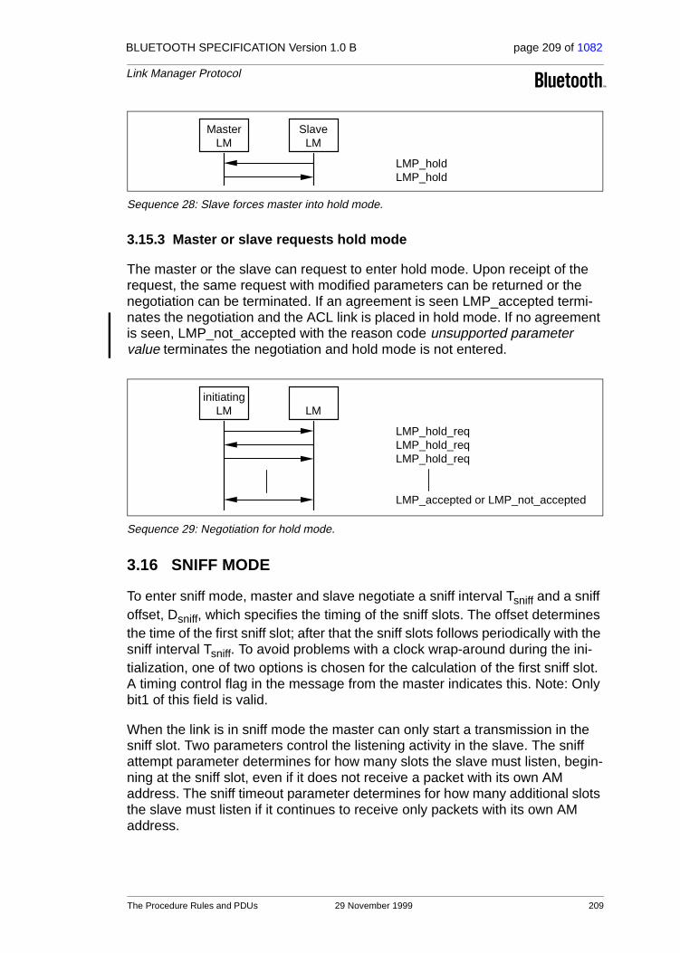
BLUETOOTH SPECIFICATION Version 1.0 B page 209 of 1082
Link Manager Protocol
Sequence 28: Slave forces master into hold mode.
3.15.3 Master or slave requests hold mode
The master or the slave can request to enter hold mode. Upon receipt of the request, the same request with modified parameters can be returned or the negotiation can be terminated. If an agreement is seen LMP_accepted termi-nates the negotiation and the ACL link is placed in hold mode. If no agreement is seen, LMP_not_accepted with the reason code unsupported parameter value terminates the negotiation and hold mode is not entered.
Sequence 29: Negotiation for hold mode.
3.16 SNIFF MODE
To enter sniff mode, master and slave negotiate a sniff interval Tsniff and a sniff offset, Dsniff, which specifies the timing of the sniff slots. The offset determines the time of the first sniff slot; after that the sniff slots follows periodically with the sniff interval Tsniff. To avoid problems with a clock wrap-around during the ini-tialization, one of two options is chosen for the calculation of the first sniff slot. A timing control flag in the message from the master indicates this. Note: Only bit1 of this field is valid.
When the link is in sniff mode the master can only start a transmission in the sniff slot. Two parameters control the listening activity in the slave. The sniff attempt parameter determines for how many slots the slave must listen, begin-ning at the sniff slot, even if it does not receive a packet with its own AM address. The sniff timeout parameter determines for how many additional slots the slave must listen if it continues to receive only packets with its own AM address.
MasterLM
SlaveLM
LMP_holdLMP_hold
initiatingLM LM
LMP_hold_reqLMP_hold_reqLMP_hold_req
LMP_accepted or LMP_not_accepted
The Procedure Rules and PDUs 29 November 1999 209

BLUETOOTH SPECIFICATION Version 1.0 B page 210 of 1082
Link Manager Protocol
3.16.1 Master forces a slave into sniff mode
Sequence 30: Master forces slave into sniff mode.
3.16.2 Master or slave requests sniff mode
The master or the slave can request to enter sniff mode. Upon receipt of the request, the same request with modified parameters can be returned or the negotiation can be terminated. If an agreement is seen LMP_accepted termi-nates the negotiation and the ACL link is placed in sniff mode. If no agreement is seen, LMP_not_accepted with the reason code unsupported parameter value terminates the negotiation and sniff mode is not entered.
Sequence 31: Negotiation for sniff mode.
M/O PDU Contents
O LMP_sniff timing control flagsDsniffTsniffsniff attemptsniff timeout
O LMP_sniff_req timing control flagsDsniffTsniffsniff attemptsniff timeout
O LMP_unsniff_req -
Table 3.16: PDUs used for sniff mode.
MasterLM
SlaveLM
LMP_sniff
initiatingLM LM
LMP_sniff_reqLMP_sniff_reqLMP_sniff_req
LMP_accepted or LMP_not_accepted
210 29 November 1999 The Procedure Rules and PDUs

BLUETOOTH SPECIFICATION Version 1.0 B page 211 of 1082
Link Manager Protocol
3.16.3 Moving a slave from sniff mode to active mode
Sniff mode is ended by sending the PDU LMP_unsniff_req. The requested device must reply with LMP_accepted. If the slave requests it will enter active mode after receiving LMP_accepted. If the master requests, the slave will enter active mode after receiving LMP_unsniff_req.
Sequence 32: Slave moved from sniff mode to active mode.
3.17 PARK MODE
If a slave does not need to participate in the channel, but still should be FH-synchronized, it can be placed in park mode. In this mode the device gives up its AM_ADDR but still re-synchronizes to the channel by waking up at the bea-con instants separated by the beacon interval. The beacon interval, a beacon offset and a flag indicating how the first beacon instant is calculated determine the first beacon instant. After this the beacon instants follow periodically at the predetermined beacon interval. At the beacon instant the parked slave can be activated again by the master, the master can change the park mode parame-ters, transmit broadcast information or let the parked slaves request access to the channel.
All PDUs sent from the master to the parked slaves are broadcast. These PDUs (LMP_set_broadcast_scan_window, LMP_modify_beacon, LMP_unpark_BD_addr_req and LMP_unpark_PM_addr_req) are the only PDUs that can be sent to a slave in park mode and the only PDUs that can be broadcast. To increase reliability for broadcast, the packets are made as short as possible. Therefore the format for these LMP PDUs are somewhat different. The parameters are not always byte-aligned and the length of the PDUs is vari-able.
The messages for controlling the park mode include many parameters, which are all defined in Baseband Specification Section 10.8.4, on page 115. When a slave is placed in park mode it is assigned a unique PM_ADDR, which can be used by the master to unpark that slave. The all-zero PM_ADDR has a special meaning; it is not a valid PM_ADDR. If a device is assigned this PM_ADDR, it must be identified with its BD_ADDR when it is unparked by the master.
initiatingLM
LM
LMP_unsniff_reqLMP_accepted
The Procedure Rules and PDUs 29 November 1999 211

BLUETOOTH SPECIFICATION Version 1.0 B page 212 of 1082
Link Manager Protocol
M/O PDU Contents
O LMP_park_req -
O LMP_park
timing control flags DBTB NB ∆B PM_ADDR AR_ADDR NBsleep DBsleep Daccess Taccess Nacc-slots Npoll Maccess access scheme
O LMP_set_broadcast_scan_windowtiming control flags DB (optional)broadcast scan window
O LMP_modify_beacon
timing control flags DB (optional)TB NB ∆B Daccess Taccess Nacc-slots NpollMaccess access scheme
O LMP_unpark_PM_ADDR_req
timing control flags DB (optional)AM_ADDRPM_ADDRAM_ADDR (optional)PM_ADDR (optional)(totally 1-7 pairs of AM_ADDR, PM_ADDR)
O LMP_unpark_BD_ADDR _req
timing control flags DB (optional)AM_ADDRBD_ADDRAM_ADDR (optional)BD_ADDR (optional)
Table 3.17: PDUs used for park mode.
212 29 November 1999 The Procedure Rules and PDUs

BLUETOOTH SPECIFICATION Version 1.0 B page 213 of 1082
Link Manager Protocol
3.17.1 Master forces a slave into park mode
The master can force park mode. The master finalizes the transmission of the current L2CAP message and then sends LMP_park. When this PDU is received by the slave, it finalizes the transmission of the current L2CAP mes-sage and then sends LMP_accepted.
Sequence 33: Slave forced into park mode.
3.17.2 Master requests slave to enter park mode
The master can request park mode. The master finalizes the transmission of the current L2CAP message and then sends LMP_park_req. If the slave accepts to enter park mode it finalizes the transmission of the current L2CAP message and then responds with LMP_accepted. Finally the master sends LMP_park. If the slave rejects park mode it sends LMP_not_accepted.
Sequence 34: Slave accepts to be placed in park mode.
Sequence 35: Slave rejects to be placed in park mode.
3.17.3 Slave requests to be placed in park mode
The slave can request park mode. The slave finalizes the transmission of the current L2CAP message and then sends LMP_park_req. If the master accepts park mode it finalizes the transmission of the current L2CAP message and then sends LMP_park. If the master rejects park mode it sends LMP_not_accepted.
MasterLM
SlaveLM
LMP_parkLMP_accepted
MasterLM
SlaveLM
LMP_park_reqLMP_acceptedLMP_park
MasterLM
SlaveLM
LMP_park_reqLMP_not_accepted
The Procedure Rules and PDUs 29 November 1999 213

BLUETOOTH SPECIFICATION Version 1.0 B page 214 of 1082
Link Manager Protocol
Sequence 36: Master accepts and places slave in park mode.
Sequence 37: Master rejects to place slave in park mode.
3.17.4 Master sets up broadcast scan window
If more broadcast capacity is needed than the beacon train, the master can indicate to the slaves that more broadcast information will follow the beacon train by sending LMP_set_broadcast_scan_window. This message is always sent in a broadcast packet at the beacon slot(s). The scan window starts in the beacon instant and is only valid for the current beacon.
Sequence 38: Master notifies all slaves of increase in broadcast capacity.
3.17.5 Master modifies beacon parameters
When the beacon parameters change the master notifies the parked slaves of this by sending LMP_modify_beacon. This message is always sent in a broad-cast packet at the beacon slot(s).
Sequence 39: Master modifies beacon parameters.
3.17.6 Unparking slaves
The master can unpark one or many slaves by sending a broadcast LMP mes-sage including the PM_ADDR or the BD_ADDR of the device(s) it wishes to
MasterLM
SlaveLM
LMP_park_reqLMP_park
MasterLM
SlaveLM
LMP_park_reqLMP_not_accepted
MasterLM
All slavesLM
LMP_set_broadcast_scan_window
MasterLM
All slavesLM
LMP_modify_beacon
214 29 November 1999 The Procedure Rules and PDUs
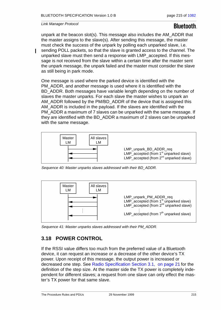
BLUETOOTH SPECIFICATION Version 1.0 B page 215 of 1082
Link Manager Protocol
unpark at the beacon slot(s). This message also includes the AM_ADDR that the master assigns to the slave(s). After sending this message, the master must check the success of the unpark by polling each unparked slave, i.e. sending POLL packets, so that the slave is granted access to the channel. The unparked slave must then send a response with LMP_accepted. If this mes-sage is not received from the slave within a certain time after the master sent the unpark message, the unpark failed and the master must consider the slave as still being in park mode.
One message is used where the parked device is identified with the PM_ADDR, and another message is used where it is identified with the BD_ADDR. Both messages have variable length depending on the number of slaves the master unparks. For each slave the master wishes to unpark an AM_ADDR followed by the PM/BD_ADDR of the device that is assigned this AM_ADDR is included in the payload. If the slaves are identified with the PM_ADDR a maximum of 7 slaves can be unparked with the same message. If they are identified with the BD_ADDR a maximum of 2 slaves can be unparked with the same message.
Sequence 40: Master unparks slaves addressed with their BD_ADDR.
Sequence 41: Master unparks slaves addressed with their PM_ADDR.
3.18 POWER CONTROL
If the RSSI value differs too much from the preferred value of a Bluetooth device, it can request an increase or a decrease of the other device’s TX power. Upon receipt of this message, the output power is increased or decreased one step. See Radio Specification Section 3.1, on page 21 for the definition of the step size. At the master side the TX power is completely inde-pendent for different slaves; a request from one slave can only effect the mas-ter’s TX power for that same slave.
MasterLM
All slavesLM
LMP_unpark_BD_ADDR_reqLMP_accepted (from 1st unparked slave)LMP_accepted (from 2nd unparked slave)
MasterLM
All slavesLM
LMP_unpark_PM_ADDR_reqLMP_accepted (from 1st unparked slave)LMP_accepted (from 2nd unparked slave)
LMP_accepted (from 7th unparked slave)
The Procedure Rules and PDUs 29 November 1999 215

BLUETOOTH SPECIFICATION Version 1.0 B page 216 of 1082
Link Manager Protocol
Sequence 42: A device requests a change of the other device’s TX power.
If the receiver of LMP_incr_power_req already transmits at maximum power LMP_max_power is returned. The device may then only request an increase again after having requested a decrease at least once. Similarly, if the receiver of LMP_decr_power_req already transmits at minimum power then LMP_min_power is returned and the device may only request a decrease again after having requested an increase at least once.
Sequence 43: The TX power cannot be increased.
Sequence 44: The TX power cannot be decreased.
One byte is reserved in LMP_incr/decr_power_req for future use. It could, for example, be the mismatch between preferred and measured RSSI. The receiver of LMP_incr/decr_power_req could then use this value to adjust to the correct power at once, instead of only changing it one step for each request. The parameter value must be 0x00 for all versions of LMP where this parame-ter is not yet defined.
M/O PDU Contents
O LMP_incr_power_req for future use (1 Byte)
O LMP_decr_power_req for future use (1 Byte)
O LMP_max_power -
O LMP_min_power -
Table 3.18: PDUs used for power control.
InitiatingLM
LM
LMP_incr_power_reqorLMP_decr_power_req
InitiatingLM
LM
LMP_incr_power_reqLMP_max_power
InitiatingLM
LM
LMP_decr_power_reqLMP_min_power
216 29 November 1999 The Procedure Rules and PDUs

BLUETOOTH SPECIFICATION Version 1.0 B page 217 of 1082
Link Manager Protocol
3.19 CHANNEL QUALITY-DRIVEN CHANGE BETWEEN DM AND DH
A device is configured to always use DM packets or to always use DH packets or to automatically adjust its packet type according to the quality of the chan-nel. Nevertheless, all devices are capable of transmitting either DM or DH packets. The difference between DM and DH is that the payload in a DM packet is protected with a 2/3 FEC code, whereas the payload of a DH is not protected with any FEC. If a device wants to automatically adjust between DM and DH it sends LMP_auto_rate to the other device. Based upon quality mea-sures in LC, the device determines if throughput will be increased by a change of packet type. If so, LMP_preferred_rate is sent to the other device. The PDUs used for this are:
Sequence 45: The left-hand unit is configured to automatically change between DM and DH.
Sequence 46: The right-hand device orders the left-hand device to change data rate.
M/O PDU Contents
O LMP_auto_rate -
O LMP_preferred_rate data rate
Table 3.19: PDUs used for quality driven change of the data rate.
LM LM
LMP_auto_rate
LM LM
LMP_preferred_rate
The Procedure Rules and PDUs 29 November 1999 217

BLUETOOTH SPECIFICATION Version 1.0 B page 218 of 1082
Link Manager Protocol
3.20 QUALITY OF SERVICE (QoS)
The Link Manager provides Quality of Service capabilities. A poll interval, which is defined as the maximum time between subsequent transmissions from the master to a particular slave, is used to support bandwidth allocation and latency control. The poll interval is guaranteed except when there are colli-sions with page, page scan, inquiry and inquiry scan.
In addition, master and slave negotiate the number of repetitions for broadcast packets (NBC), see Baseband Specification Section 5.3, on page 68.
3.20.1 Master notifies slave of the quality of service
In this case the master notifies the slave of the new poll interval and NBC. The slave cannot reject the notification.
Sequence 47: Master notifies slave of new quality of service.
M/O PDU Contents
M LMP_quality_of_service poll interval
NBC
M LMP_quality_of_service_req poll interval
NBC
Table 3.20: PDUs used for quality of service.
MasterLM
SlaveLM
LMP_quality_of_service
218 29 November 1999 The Procedure Rules and PDUs

BLUETOOTH SPECIFICATION Version 1.0 B page 219 of 1082
Link Manager Protocol
3.20.2 Device requests new quality of service
In this case the master or slave requests a new poll interval and NBC. The parameter NBC is meaningful only when it is sent by a master to a slave. For transmission of LMP_quality_of_service_req PDUs from a slave, this parameter is ignored by the master. The request can be accepted or rejected. This will allow the master and slave to dynamically negotiate the quality of ser-vice as needed.
Sequence 48: Device accepts new quality of service
Sequence 49: Device rejects new quality of service.
3.21 SCO LINKS
When a connection has been established between two Bluetooth devices the connection consists of an ACL link. One or more SCO links can then be estab-lished. The SCO link reserves slots separated by the SCO interval, Tsco. The first slot reserved for the SCO link is defined by Tsco and the SCO delay, Dsco. After that the SCO slots follows periodically with the SCO interval. To avoid problems with a wrap-around of the clock during initialization of the SCO link, a flag indicating how the first SCO slot should be calculated is included in a mes-sage from the master. Note: Only bit0 and bit1 of this field is valid. Each SCO link is distinguished from all other SCO links by an SCO handle. The SCO han-dle zero is never used.
M/O PDU Contents
O LMP_SCO_link_req
SCO handle timing control flags DscoTscoSCO packet air mode
O LMP_remove_SCO_link_reqSCO handlereason
Table 3.21: PDUs used for managing the SCO links.
InitiatingLM LM
LMP_quality_of_service_reqLMP_accepted
InitiatingLM LM
LMP_quality_of_service_reqLMP_not_accepted
The Procedure Rules and PDUs 29 November 1999 219
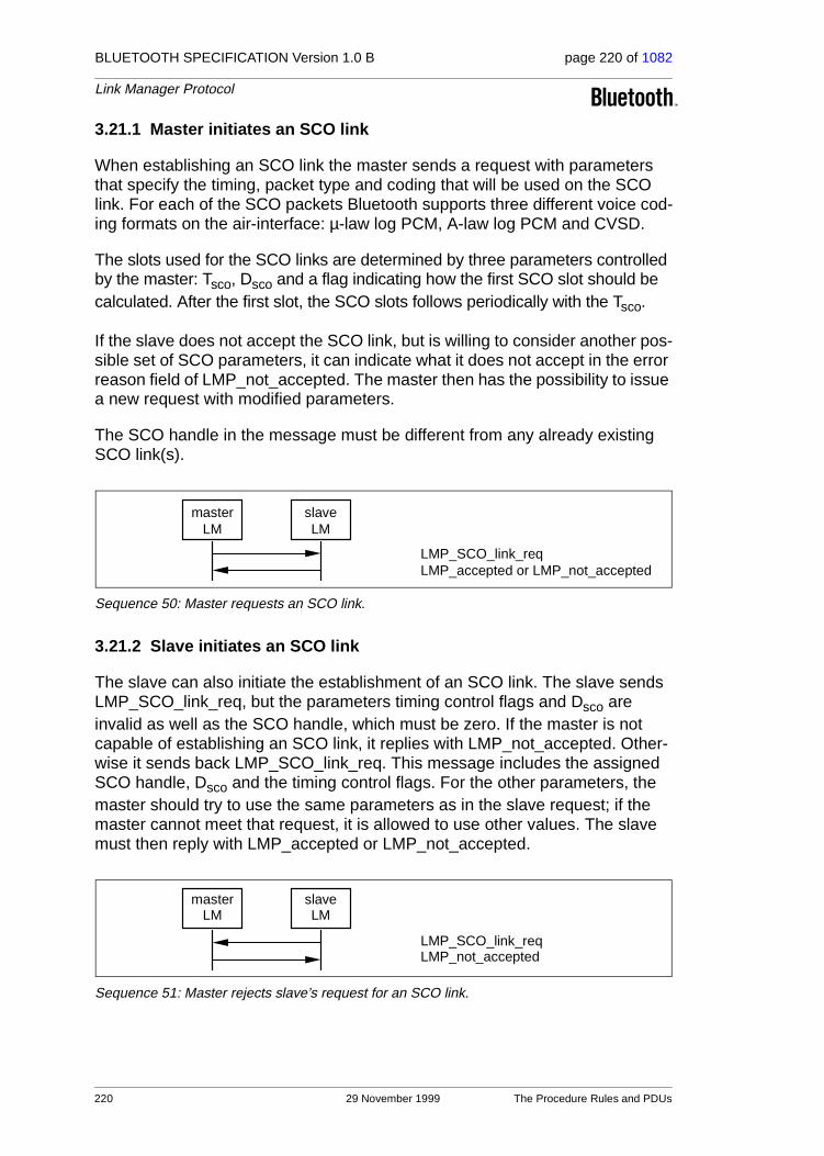
BLUETOOTH SPECIFICATION Version 1.0 B page 220 of 1082
Link Manager Protocol
3.21.1 Master initiates an SCO link
When establishing an SCO link the master sends a request with parameters that specify the timing, packet type and coding that will be used on the SCO link. For each of the SCO packets Bluetooth supports three different voice cod-ing formats on the air-interface: µ-law log PCM, A-law log PCM and CVSD.
The slots used for the SCO links are determined by three parameters controlled by the master: Tsco, Dsco and a flag indicating how the first SCO slot should be calculated. After the first slot, the SCO slots follows periodically with the Tsco.
If the slave does not accept the SCO link, but is willing to consider another pos-sible set of SCO parameters, it can indicate what it does not accept in the error reason field of LMP_not_accepted. The master then has the possibility to issue a new request with modified parameters.
The SCO handle in the message must be different from any already existing SCO link(s).
Sequence 50: Master requests an SCO link.
3.21.2 Slave initiates an SCO link
The slave can also initiate the establishment of an SCO link. The slave sends LMP_SCO_link_req, but the parameters timing control flags and Dsco are invalid as well as the SCO handle, which must be zero. If the master is not capable of establishing an SCO link, it replies with LMP_not_accepted. Other-wise it sends back LMP_SCO_link_req. This message includes the assigned SCO handle, Dsco and the timing control flags. For the other parameters, the master should try to use the same parameters as in the slave request; if the master cannot meet that request, it is allowed to use other values. The slave must then reply with LMP_accepted or LMP_not_accepted.
Sequence 51: Master rejects slave’s request for an SCO link.
masterLM
slaveLM
LMP_SCO_link_reqLMP_accepted or LMP_not_accepted
masterLM
slaveLM
LMP_SCO_link_reqLMP_not_accepted
220 29 November 1999 The Procedure Rules and PDUs

BLUETOOTH SPECIFICATION Version 1.0 B page 221 of 1082
Link Manager Protocol
Sequence 52: Master accepts slave’s request for an SCO link.
3.21.3 Master requests change of SCO parameters
The master sends LMP_SCO_link_req, where the SCO handle is the handle of the SCO link the master wishes to change parameters for. If the slave accepts the new parameters, it replies with LMP_accepted and the SCO link will change to the new parameters. If the slave does not accept the new parame-ters, it replies with LMP_not_accepted and the SCO link is left unchanged. When the slave replies with LMP_not_accepted it shall indicate in the error rea-son parameter what it does not accept. The master can then try to change the SCO link again with modified parameters. The sequence is the same as in Section 3.21.1 on page 220.
3.21.4 Slave requests change of SCO parameters
The slave sends LMP_SCO_link_req, where the SCO handle is the handle of the SCO link the slave wishes to change parameters for. The parameters tim-ing control flags and Dsco are not valid in this message. If the master does not accept the new parameters it replies with LMP_not_accepted and the SCO link is left unchanged. If the master accepts the new parameters it replies with LMP_SCO_link_req, where it must use the same parameters as in the slave request. When receiving this message the slave replies with LMP_not_accepted if it does not accept the new parameters. The SCO link is then left unchanged. If the slave accepts the new parameters it replies with LMP_accepted and the SCO link will change to the new parameters. The sequence is the same as in Section 3.21.2 on page 220.
3.21.5 Remove an SCO link
Master or slave can remove the SCO link by sending a request including the SCO handle of the SCO link to be removed and a reason indicating why the SCO link is removed. The receiving party must respond with LMP_accepted.
Sequence 53: SCO link removed.
masterLM
slaveLM
LMP_SCO_link_reqLMP_SCO_link_reqLMP_accepted or LMP_not_accepted
initiatingLM LM
LMP_remove_SCO_link_reqLMP_accepted
The Procedure Rules and PDUs 29 November 1999 221

BLUETOOTH SPECIFICATION Version 1.0 B page 222 of 1082
Link Manager Protocol
3.22 CONTROL OF MULTI-SLOT PACKETS
The number of slots used by a slave in its return packet can be limited. The master allows the slave to use a maximal number of slots by sending the PDU LMP_max_slots providing max slots as parameter. Each slave can request to use a maximal number of slots by sending the PDU LMP_max_slot_req provid-ing max slots as parameter. The default value is 1 slot, i.e. if the slave has not been informed about the number of slots, it may only use 1-slot packets. Two PDUs are used for the control of multi-slot packets.
Sequence 54: Master allows slave to use a maximal number of slots.
Sequence 55: Slave requests to use a maximal number of slots. Master accepts.
Sequence 56: Slave requests to use a maximal number of slots. Master rejects.
M/O PDU Contents
M LMP_max_slot max slots
M LMP_max_slot_req max slots
Table 3.22: PDUs used to control the use of multi-slot packets.
MasterLM
SlaveLM
LMP_max_slot
MasterLM
SlaveLM
LMP_max_slot_reqLMP_accepted
MasterLM
SlaveLM
LMP_max_slot_reqLMP_not_accepted
222 29 November 1999 The Procedure Rules and PDUs

BLUETOOTH SPECIFICATION Version 1.0 B page 223 of 1082
Link Manager Protocol
3.23 PAGING SCHEME
In addition to the mandatory paging scheme, Bluetooth defines optional paging schemes; see “Appendix VII” on page 999. LMP provides a means to negotiate the paging scheme, which is to be used the next time a unit is paged.
3.23.1 Page mode
This procedure is initiated from device A and negotiates the paging scheme used when device A pages device B. Device A proposes a paging scheme including the parameters for this scheme and device B can accept or reject. On rejection the old setting is not changed. A request to switch back to the manda-tory scheme may be rejected.
Sequence 57: Negotiation for page mode.
3.23.2 Page scan mode
This procedure is initiated from device A and negotiates the paging scheme used when device B pages device A. Device A proposes a paging scheme including the parameters for this scheme and device B can accept or reject. On rejection the old setting is not changed. A request to switch to the mandatory scheme must be accepted.
Sequence 58: Negotiation for page scan mode
M/O PDU Contents
O LMP_page_mode_req paging scheme
paging scheme settings
O LMP_page_scan_mode_req paging scheme
paging scheme settings
Table 3.23: PDUs used to request paging scheme.
ALM
BLM
LMP_page_mode_reqLMP_accepted or LMP_not_accepted
ALM
BLM
LMP_page_scan_mode_reqLMP_accepted or LMP_not_accepted
The Procedure Rules and PDUs 29 November 1999 223

BLUETOOTH SPECIFICATION Version 1.0 B page 224 of 1082
Link Manager Protocol
3.24 LINK SUPERVISION
Each Bluetooth link has a timer that is used for link supervision. This timer is used to detect link loss caused by devices moving out of range, a device’s power-down, or other similar failure cases. The scheme for link supervision is described in Baseband Specification Section 10.11, on page 126. An LMP pro-cedure is used to set the value of the supervision timeout.
Sequence 59: Setting the link supervision timeout.
M/O PDU Contents
M LMP_supervision_timeout supervision timeout
Table 3.24: PDU used to set the supervision timeout.
masterLM
slaveLM
LMP_supervision_timeout
224 29 November 1999 The Procedure Rules and PDUs
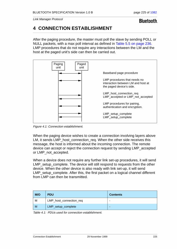
BLUETOOTH SPECIFICATION Version 1.0 B page 225 of 1082
Link Manager Protocol
4 CONNECTION ESTABLISHMENT
After the paging procedure, the master must poll the slave by sending POLL or NULL packets, with a max poll interval as defined in Table 5.5 on page 236. LMP procedures that do not require any interactions between the LM and the host at the paged unit’s side can then be carried out.
Figure 4.1: Connection establishment.
When the paging device wishes to create a connection involving layers above LM, it sends LMP_host_connection_req. When the other side receives this message, the host is informed about the incoming connection. The remote device can accept or reject the connection request by sending LMP_accepted or LMP_not_accepted.
When a device does not require any further link set-up procedures, it will send LMP_setup_complete. The device will still respond to requests from the other device. When the other device is also ready with link set-up, it will send LMP_setup_complete. After this, the first packet on a logical channel different from LMP can then be transmitted.
M/O PDU Contents
M LMP_host_connection_req -
M LMP_setup_complete -
Table 4.1: PDUs used for connection establishment.
Pagingunit
Pagedunit
Baseband page procedure
LMP procedures that needs nointeraction between LM and host atthe paged device’s side.
LMP_host_connection_reqLMP_accepted or LMP_not_accepted
LMP procedures for pairing,authentication and encryption.
LMP_setup_completeLMP_setup_complete
Connection Establishment 29 November 1999 225

BLUETOOTH SPECIFICATION Version 1.0 B page 226 of 1082
Link Manager Protocol
5 SUMMARY OF PDUs
LMP PDU Length (bytes)
op code
Packet type
Possible direction
ContentsPosition in payload
LMP_accepted 2 3DM1/DV
m ↔ s op code 2
LMP_au_rand 17 11 DM1 m ↔ s random number 2-17
LMP_auto_rate 1 35DM1/DV
m ↔ s -
LMP_clkoffset_req 1 5DM1/DV
m → s -
LMP_clkoffset_res 3 6DM1/DV
m ← s clock offset 2–3
LMP_comb_key 17 9 DM1 m ↔ s random number 2-17
LMP_decr_power_req 2 32DM1/DV
m ↔ s for future use 2
LMP_detach 2 7DM1/DV
m ↔ s reason 2
LMP_encryption_key_size_req
2 16DM1/DV
m ↔ s key size 2
LMP_encryption_mode_req
2 15DM1/DV
m ↔ s encryption mode 2
LMP_features_req 9 39DM1/DV
m ↔ s features 2-9
LMP_features_res 9 40DM1/DV
m ↔ s features 2-9
LMP_host_connection_req 1 51DM1/DV
m ↔ s -
LMP_hold 3 20DM1/DV
m ↔ s hold time 2-3
LMP_hold_req 3 21DM1/DV
m ↔ s hold time 2-3
LMP_incr_power_req 2 31DM1/DV
m ↔ s for future use 2
LMP_in_rand 17 8 DM1 m ↔ s random number 2-17
LMP_max_power 1 33DM1/DV
m ↔ s -
Table 5.1: Coding of the different LM PDUs.
226 29 November 1999 Summary of PDUs

BLUETOOTH SPECIFICATION Version 1.0 B page 227 of 1082
Link Manager Protocol
LMP_max_slot 2 45DM1/DV
m → s max slots 2
LMP_max_slot_req 2 46DM1/DV
m ← s max slots 2
LMP_min_power 1 34DM1/DV
m ↔ s -
LMP_modify_beacon11or 13
28 DM1 m → s
timing control flags 2
DB 3-4
TB 5-6
NB 7
∆B 8
Daccess 9
Taccess 10
Nacc-slots 11
Npoll 12
Maccess 13:0-3
access scheme 13:4-7
LMP_name_req 2 1DM1/DV
m ↔ s name offset 2
LMP_name_res 17 2 DM1 m ↔ s
name offset 2
name length 3
name fragment 4-17
LMP_not_accepted 3 4DM1/DV
m ↔ sop code 2
reason 3
LMP_page_mode_req 3 53DM1/DV
m ↔ spaging scheme 2
paging scheme settings 3
LMP_page_scan_mode_req
3 54DM1/DV
m ↔ spaging scheme 2
paging scheme settings 3
LMP PDULength (bytes)
op code
Packet type
Possible direction Contents
Position in payload
Table 5.1: Coding of the different LM PDUs.
Summary of PDUs 29 November 1999 227

BLUETOOTH SPECIFICATION Version 1.0 B page 228 of 1082
Link Manager Protocol
LMP_park 17 26 DM m → s
timing control flags 2
DB 3-4
TB 5-6
NB 7
∆B 8
PM_ADDR 9
AR_ADDR 10
NBsleep 11
DBsleep 12
Daccess 13
Taccess 14
Nacc-slots 15
Npoll 16
Maccess 17:0-3
access scheme 17:4-7
LMP_park_req 1 25DM1/DV
m ↔ s -
LMP_preferred_rate 2 36DM1/DV
m ↔ s data rate 2
LMP_quality_of_service 4 41DM1/DV
m → spoll interval 2-3
NBC 4
LMP_quality_of_service_req
4 42DM1/DV
m ↔ spoll interval 2-3
NBC 4
LMP_remove_SCO_link_req
3 44DM1/DV
m ↔ sSCO handle 2
reason 3
LMP PDULength (bytes)
op code
Packet type
Possible direction Contents
Position in payload
Table 5.1: Coding of the different LM PDUs.
228 29 November 1999 Summary of PDUs

BLUETOOTH SPECIFICATION Version 1.0 B page 229 of 1082
Link Manager Protocol
LMP_SCO_link_req 7 43DM1/DV
m ↔ s
SCO handle 2
timing control flags 3
Dsco 4
Tsco 5
SCO packet 6
air mode 7
LMP_set_broadcast_scan_window
4 or 6 27 DM1 m → s
timing control flags 2
DB 3-4
broadcast scan window 5-6
LMP_setup_complete 1 49 DM1 m ↔ s -
LMP_slot_offset 9 52DM1/DV
m ↔ sslot offset 2-3
BD_ADDR 4-9
LMP_sniff 10 22 DM1 m → s
timing control flags 2
Dsniff 3-4
Tsniff 5-6
sniff attempt 7-8
sniff timeout 9-10
LMP_sniff_req 10 23 DM1 m ↔ s
timing control flags 2
Dsniff 3-4
Tsniff 5-6
sniff attempt 7-8
sniff timeout 9-10
LMP_sres 5 12DM1/DV
m ↔ s authentication response 2-5
LMP_start_encryption_req 17 17 DM1 m → s random number 2-17
LMP_stop_encryption_req 1 18DM1/DV
m → s -
LMP_supervision_timeout
3 55DM1/DV
m ↔ s supervision timeout 2-3
LMP_switch_req 1 19DM1/DV
m ↔ s -
LMP PDULength (bytes)
op code
Packet type
Possible direction Contents
Position in payload
Table 5.1: Coding of the different LM PDUs.
Summary of PDUs 29 November 1999 229

BLUETOOTH SPECIFICATION Version 1.0 B page 230 of 1082
Link Manager Protocol
Note1: For LMP_set_broadcast_scan_window, LMP_modify_beacon, LMP_unpark_BD_ADDR_req and LMP_unpark_PM_ADDR_req the parameter
LMP_temp_rand 17 13 DM1 m → s random number 2-17
LMP_temp_key 17 14 DM1 m → s key 2-17
LMP_timing_accuracy_req 1 47DM1/DV
m ↔ s -
LMP_timing_accuracy_res 3 48DM1/DV
m ↔ sdrift 2
jitter 3
LMP_unit_key 17 10 DM1 m ↔ s key 2-17
LMP_unpark_BD_ADDR_req
variable 29 DM1 m → s
timing control flags 2
DB 3-4
AM_ADDR 1st unpark 5:0-3
AM_ADDR 2nd unpark 5:4-7
BD_ADDR 1st unpark 6-11
BD_ADDR 2nd unpark 12-17
LMP_unpark_PM_ADDR_req
variable 30 DM1 m → s
timing control flags 2
DB 3-4
AM_ADDR 1st unpark 5:0-3
AM_ADDR 2nd unpark 5:4-7
PM_ADDR 1st unpark 6
PM_ADDR 2nd unpark 7
LMP_unsniff_req 1 24DM1/DV
m ↔ s -
LMP_use_semi_permanent_key
1 50DM1/DV
m → s -
LMP_version_req 6 37DM1/DV
m ↔ s
VersNr 2
CompId 3-4
SubVersNr 5-6
LMP_version_res 6 38DM1/DV
m ↔ s
VersNr 2
CompId 3-4
SubVersNr 5-6
LMP PDULength (bytes)
op code
Packet type
Possible direction Contents
Position in payload
Table 5.1: Coding of the different LM PDUs.
230 29 November 1999 Summary of PDUs

BLUETOOTH SPECIFICATION Version 1.0 B page 231 of 1082
Link Manager Protocol
DB is optional. This parameter is only present if bit0 of timing control flags is 0. If the parameter is not included, the position in payload for all parameters fol-lowing DB are decreased by 2.
Note2: For LMP_unpark_BD_ADDR the AM_ADDR and the BD_ADDR of the 2nd unparked slave are optional. If only one slave is unparked AM_ADDR 2nd unpark should be zero and BD_ADDR 2nd unpark is left out.
Note3: For LMP_unpark_PM_ADDR the AM_ADDR and the PM_ADDR of the 2nd – 7th unparked slaves are optional. If N slaves are unparked, the fields up to and including the Nth unparked slave are present. If N is odd, the AM_ADDR (N+1)th unpark must be zero. The length of the message is x + 3N/2 if N is even and x + 3(N+1)/2 -1 if N is odd, where x = 2 or 4 depending on if the DB is incluDed Or Not (See Note1).
5.1 DESCRIPTION OF PARAMETERS
NameLength (bytes) Type Unit Detailed
access scheme 1 u_int40: polling technique
1-15: Reserved
air mode 1 u_int8
0: µ-law log
1: A-law log
2: CVSD
3-255: Reserved
AM_ADDR 1 u_int4
AR_ADDR 1 u_int8
authentication response
4 multiple bytes
BD_ADDR 6 multiple bytes
broadcast scan window
2 u_int16 slots
clock offset 2 u_int16 1.25ms
(CLKN16-2 slave -
CLKN16-2 master) mod 215
MSbit of second byte not used.
CompId 2 u_int16see BT Assigned Numbers Section 2.1 on page 1018
Daccess 1 u_int8 slots
DB 2 u_int16 slots
Table 5.2: Parameters in LM PDUs.
Summary of PDUs 29 November 1999 231

BLUETOOTH SPECIFICATION Version 1.0 B page 232 of 1082
Link Manager Protocol
DBsleep 1 u_int8 slots
data rate 1 u_int8
0: medium rate
1: high rate
2-255: Reserved
drift 1 u_int8 ppm
Dsco 1 u_int8 slots
Dsniff 2 u_int16 slots
encryption mode 1 u_int8
0: no encryption
1: point-to-point encryption
2: point-to-point and broadcast encryption
3 -255: Reserved
features 8 multiple bytes See Table 5.3 on page 234
hold time 2 u_int16 slots
jitter 1 u_int8 µs
key 16 multiple bytes
key size 1 u_int8 byte
Maccess 1 u_int4 slots
max slots 1 u_int8 slots
Nacc-slots 1 u_int8 slots
name fragment 14 multiple bytes UTF-8 characters.
name length 1 u_int8 bytes
name offset 1 u_int8 bytes
NB 1 u_int8
NBC 1 u_int8
NBsleep 1 u_int8 slots
Npoll 1 u_int8 slots
op code 1 u_int8
paging scheme 1 u_int8
0: mandatory scheme
1: optional scheme 1
2-255: Reserved
Name Length (bytes)
Type Unit Detailed
Table 5.2: Parameters in LM PDUs.
232 29 November 1999 Summary of PDUs

BLUETOOTH SPECIFICATION Version 1.0 B page 233 of 1082
Link Manager Protocol
paging scheme settings
1 u_int8
For mandatory scheme:
0: R0
1: R1
2: R2
3-255: Reserved
For optional scheme 1:
0: Reserved
1: R1
2: R2
3-255: Reserved
PM_ADDR 1 u_int8
poll interval 2 u_int16 slots
random number 16 multiple bytes
reason 1 u_int8See Table 5.4 on page 235.
SCO handle 1 u_int8
SCO packet 1 u_int8
0: HV1
1: HV2
2: HV3
3-255: Reserved
slot offset 2 u_int16 µs 0 ≤ slot offset < 1250
sniff attempt 2 u_int16 slots
sniff timeout 2 u_int16 slots
SubVersNr 2 u_int16 Defined by each company
supervision time-out
2 u_int16 slots
Taccess 1 u_int8 slots
TB 2 u_int16 slots
timing control flags
1 u_int8
bit0 = 0: no timing change
bit0 = 1: timing change
bit1 = 0: use initialization 1
bit1 = 1: use initialization 2
bit2 = 0: access window
bit2 = 1: no access window
bit3-7: Reserved
Name Length (bytes)
Type Unit Detailed
Table 5.2: Parameters in LM PDUs.
Summary of PDUs 29 November 1999 233

BLUETOOTH SPECIFICATION Version 1.0 B page 234 of 1082
Link Manager Protocol
5.1.1 Coding of features
This parameter is a bitmap with information about the Bluetooth radio-, base-band- and LMP features which a device supports. The bit shall be one if the feature is supported. The feature parameter bits that are not defined in Table 5.3 shall be zero.
Tsco 1 u_int8 slots
Tsniff 2 u_int16 slots
VersNr 1 u_int80: Bluetooth LMP 1.0
1-255: Reserved
∆B 1 u_int8 slots
Byte Bit Supported feature
0
0 3-slot packets
1 5-slot packets
2 encryption
3 slot offset
4 timing accuracy
5 switch
6 hold mode
7 sniff mode
1
0 park mode
1 RSSI
2 channel quality driven data rate
3 SCO link
4 HV2 packets
5 HV3 packets
6 u-law log
7 A-law log
2
0 CVSD
1 paging scheme
2 power control
Table 5.3: Coding of the parameter features.
Name Length (bytes)
Type Unit Detailed
Table 5.2: Parameters in LM PDUs.
234 29 November 1999 Summary of PDUs

BLUETOOTH SPECIFICATION Version 1.0 B page 235 of 1082
Link Manager Protocol
5.1.2 List of error reasons
The following table contains the codes of the different error reasons used in LMP.
Reason Description
0x05 Authentication Failure
0x06 Key Missing
0x0AMax Number Of SCO Connections To A Device (The maximum number of SCO connections to a particle device has been reached. All allowed SCO connection handles to that device are used.)
0x0DHost Rejected due to limited resources (The host at the remote side has rejected the connection because the remote host did not have enough addi-tional resources to accept the connection.)
0x0EHost Rejected due to security reasons (The host at the remote side has rejected the connection because the remote host determined that the local host did not meet its security criteria.)
0x0F
Host Rejected due to remote device is only a personal device (The host at the remote side has rejected the connection because the remote host is a personal device and will only accept the connection from one particle remote host.)
0x10Host Timeout (Used at connection accept timeout, the host did not respond to an incoming connection attempt before the connection accept timer expired.)
0x13 Other End Terminated Connection: User Ended Connection
0x14 Other End Terminated Connection: Low Resources
0x15 Other End Terminated Connection: About to Power Off
0x16 Connection Terminated by Local Host
0x17Repeated Attempts (An authentication or pairing attempt is made too soon after a previously failed authentication or pairing attempt.)
0x18 Pairing Not Allowed
0x19 Unknown LMP PDU
0x1A Unsupported LMP Feature
0x1B SCO Offset Rejected
0x1C SCO Interval Rejected
0x1D SCO Air Mode Rejected
0x1E Invalid LMP Parameters
0x1F Unspecified Error
0x20 Unsupported parameter value
0x21 Switch not allowed
0x23 LMP Error Transaction Collision
0x24 PDU not allowed
Table 5.4: List of error reasons.
Summary of PDUs 29 November 1999 235

BLUETOOTH SPECIFICATION Version 1.0 B page 236 of 1082
Link Manager Protocol
5.2 DEFAULT VALUES
The Bluetooth device must use these values before anything else has been negotiated:
Parameter Value
drift 250
jitter 10
max slots 1
poll interval 40
Table 5.5: Default values.
236 29 November 1999 Summary of PDUs

BLUETOOTH SPECIFICATION Version 1.0 B page 237 of 1082
Link Manager Protocol
6 TEST MODES
LMP has PDUs to support different Bluetooth test modes, which are used for certification and compliance testing of the Bluetooth radio and baseband. See “Bluetooth Test Mode” on page 803 for a detailed description of these test modes.
6.1 ACTIVATION AND DEACTIVATION OF TEST MODE
The test mode is activated by sending LMP_test_activate to the device under test (DUT). The DUT is always the slave. The link manager must be able to receive this message anytime. If entering test mode is locally enabled in the DUT it responds with LMP_accepted and test mode is entered. Otherwise the DUT responds with LMP_not_accepted and the DUT remains in normal opera-tion. The reason code in LMP_not_accepted shall be PDU not allowed.
Sequence 60: Activation of test mode successful.
Sequence 61: Activation of test mode fails. Slave is not allowed to enter test mode.
The test mode can be deactivated in two ways. Sending LMP_test_control with the test scenario set to "exit test mode" exits the test mode and the slave returns to normal operation still connected to the master. Sending LMP_detach to the DUT ends the test mode and the connection.
6.2 CONTROL OF TEST MODE
When the DUT has entered test mode, the PDU LMP_test_control can be sent to the DUT to start a specific test. This PDU is acknowledged with LMP_accepted. If a device that is not in test mode receives LMP_test_control it responds with LMP_not_accepted, where the reason code shall be PDU not allowed.
MasterLM
SlaveLM
LMP_test_activateLMP_accepted
MasterLM
SlaveLM
LMP_test_activateLMP_not_accepted
Test Modes 29 November 1999 237

BLUETOOTH SPECIFICATION Version 1.0 B page 238 of 1082
Link Manager Protocol
Sequence 62: Control of test mode successful.
Sequence 63: Control of test mode rejected since slave is not in test mode.
6.3 SUMMARY OF TEST MODE PDUs
The PDUs used for test purposes are summarized in the following table. For a detailed description of the parameters, see Bluetooth Test Mode Table 3.2 on page 817.
M/O
LMP PDU
Len
gth
op
co
de
Packettype
Possibledirection Contents
Positioninpayload
M LMP_test_activate 1 56 DM1/DV m → s -
M LMP_test_control 10 57 DM1 m → s
test scenario 2
hopping mode 3
TX frequency 4
RX frequency 5
power control mode 6
poll period 7
packet type 8
length of test data 9-10
Table 6.1: Test mode PDUs.
MasterLM
SlaveLM
LMP_test_controlLMP_accepted
MasterLM
SlaveLM
LMP_test_controlLMP_not_accepted
238 29 November 1999 Test Modes

BLUETOOTH SPECIFICATION Version 1.0 B page 239 of 1082
Link Manager Protocol
7 ERROR HANDLING
If the Link Manager receives a PDU with unrecognized opcode, it responds with LMP_not_accepted with the reason code unknown LMP PDU. The opcode parameter that is echoed back is the unrecognized opcode.
If the Link Manager receives a PDU with invalid parameters, it responds with LMP_not_accepted with the reason code invalid LMP parameters.
If the maximum response time, see Section 1 on page 191, is exceeded or if a link loss is detected (see Baseband Specification Section 10.11, on page 126), the party that waits for the response shall conclude that the procedure has ter-minated unsuccessfully.
Erroneous LMP messages can be caused by errors on the channel or system-atic errors at the transmit side. To detect the latter case, the LM should monitor the number of erroneous messages and disconnect if it exceeds a threshold, which is implementation-dependent.
Since LMP PDUs are not interpreted in real time, collision situations can occur where both LMs initiate the same procedure and both cannot be completed. In this situation, the master shall reject the slave-initiated procedure by sending LMP_not_accepted with the reason code ’LMP Error Transaction Collision’. The master-initiated procedure shall then be completed.
Error Handling 29 November 1999 239

BLUETOOTH SPECIFICATION Version 1.0 B page 240 of 1082
Link Manager Protocol
240 29 November 1999 Error Handling

BLUETOOTH SPECIFICATION Version 1.0 B page 241 of 1082
Link Manager Protocol
8 LIST OF FIGURES
Figure 1.1: Link Manager’s place on the global scene...............................191Figure 2.1: Payload body when LM PDUs are sent. ..................................192Figure 3.1: Symbols used in sequence diagrams. .....................................193
Sequence 1: Authentication. Claimant has link key. ................................194Sequence 2: Authentication fails. Claimant has no link key. ....................194Sequence 3: Claimant accepts pairing. ...................................................195Sequence 4: Claimant accepts pairing but requests to be verifier. ..........196Sequence 5: Unsuccessful switch of claimant-verifier role. .....................196Sequence 6: Claimant rejects pairing. .....................................................196Sequence 7: Creation of the link key. ......................................................197Sequence 8: Successful change of the link key. ......................................197Sequence 9: Change of the link key not possible since the other
unit uses a unit key. ............................................................198Sequence 10: Change to a temporary link key. .........................................199Sequence 11: Link key changed to the semi-permanent link key. .............199Sequence 12: Negotiation for encryption mode. ........................................200Sequence 13: Encryption key size negotiation successful. .......................200Sequence 14: Encryption key size negotiation failed. ................................201Sequence 15: Start of encryption. ..............................................................201Sequence 16: Stop of encryption. ..............................................................202Sequence 17: Clock offset requested. .......................................................203Sequence 18: Slot offset information is sent. .............................................203Sequence 19: The requested device supports timing accuracy
information. .........................................................................204Sequence 20: The requested device does not support timing
accuracy information. ..........................................................204Sequence 21: Request for LMP version. ...................................................205Sequence 22: Request for supported features. .........................................206Sequence 23: Master-slave switch accepted. ............................................206Sequence 24: Master-slave switch not accepted. ......................................207Sequence 25: Device’s name requested and it responses. .......................207Sequence 26: Connection closed by sending LMP_detach. ......................208Sequence 27: Master forces slave into hold mode. ...................................208Sequence 28: Slave forces master into hold mode. ..................................209Sequence 29: Negotiation for hold mode. ..................................................209Sequence 30: Master forces slave into sniff mode. ...................................210Sequence 31: Negotiation for sniff mode. ..................................................210Sequence 32: Slave moved from sniff mode to active mode. ....................211Sequence 33: Slave forced into park mode. ..............................................213Sequence 34: Slave accepts to be placed in park mode. ..........................213
List of Figures 29 November 1999 241

BLUETOOTH SPECIFICATION Version 1.0 B page 242 of 1082
Link Manager Protocol
Sequence 35: Slave rejects to be placed in park mode. ............................213Sequence 36: Master accepts and places slave in park mode. .................214Sequence 37: Master rejects to place slave in park mode. .......................214Sequence 38: Master notifies all slaves of increase in broadcast
capacity. .............................................................................214Sequence 39: Master modifies beacon parameters. .................................214Sequence 40: Master unparks slaves addressed with their BD_ADDR. ...215Sequence 41: Master unparks slaves addressed with their PM_ADDR. ...215Sequence 42: A device requests a change of the other device’s
TX power. ...........................................................................216Sequence 43: The TX power cannot be increased. ...................................216Sequence 44: The TX power cannot be decreased. .................................216Sequence 45: The left-hand unit is configured to automatically
change between DM and DH. ............................................217Sequence 46: The right-hand device orders the left-hand device
to change data rate. ............................................................217Sequence 47: Master notifies slave of new quality of service. ..................218Sequence 48: Device accepts new quality of service ................................219Sequence 49: Device rejects new quality of service. .................................219Sequence 50: Master requests an SCO link. .............................................220Sequence 51: Master rejects slave’s request for an SCO link. ..................220Sequence 52: Master accepts slave’s request for an SCO link. ................221Sequence 53: SCO link removed. .............................................................221Sequence 54: Master allows slave to use a maximal number of slots. .....222Sequence 55: Slave requests to use a maximal number of slots.
Master accepts. ..................................................................222Sequence 56: Slave requests to use a maximal number of slots.
Master rejects. ....................................................................222Sequence 57: Negotiation for page mode. ................................................223Sequence 58: Negotiation for page scan mode .........................................223Sequence 59: Setting the link supervision timeout. ...................................224
Figure 4.1: Connection establishment. ......................................................225
Sequence 60: Activation of test mode successful. ....................................237Sequence 61: Activation of test mode fails. Slave is not allowed to
enter test mode. ..................................................................237Sequence 62: Control of test mode successful. ........................................238Sequence 63: Control of test mode rejected since slave is not in
test mode. ...........................................................................238
242 29 November 1999 List of Figures

BLUETOOTH SPECIFICATION Version 1.0 B page 243 of 1082
Link Manager Protocol
9 LIST OF TABLES
Table 2.1: Logical channel L_CH field contents........................................192Table 3.1: General response messages. ..................................................193Table 3.2: PDUs used for authentication. .................................................194Table 3.3: PDUs used for pairing. ............................................................195Table 3.4: PDUs used for change of link key. ...........................................197Table 3.5: PDUs used to change the current link key. ..............................198Table 3.6: PDUs used for handling encryption..........................................199Table 3.7: PDUs used for clock offset request..........................................202Table 3.8: PDU used for slot offset information. ......................................203Table 3.9: PDUs used for requesting timing accuracy information. ..........204Table 3.10: PDUs used for LMP version request........................................205Table 3.11: PDUs used for features request...............................................206Table 3.12: PDU used for master slave switch. ..........................................206Table 3.13: PDUs used for name request...................................................207Table 3.14: PDU used for detach................................................................207Table 3.15: PDUs used for hold mode. .......................................................208Table 3.16: PDUs used for sniff mode. .......................................................210Table 3.17: PDUs used for park mode........................................................212Table 3.18: PDUs used for power control. ..................................................216Table 3.19: PDUs used for quality driven change of the data rate.............217Table 3.20: PDUs used for quality of service. ............................................218Table 3.21: PDUs used for managing the SCO links. .................................219Table 3.22: PDUs used to control the use of multi-slot packets..................222Table 3.23: PDUs used to request paging scheme.....................................223Table 3.24: PDU used to set the supervision timeout. ................................224Table 4.1: PDUs used for connection establishment. ...............................225Table 5.1: Coding of the different LM PDUs. ............................................226Table 5.2: Parameters in LM PDUs. .........................................................231Table 5.3: Coding of the parameter features. ...........................................234Table 5.4: List of error reasons. ................................................................235Table 5.5: Default values. .........................................................................236Table 6.1: Test mode PDUs. .....................................................................238
List of Tables 29 November 1999 243

BLUETOOTH SPECIFICATION Version 1.0 B page 244 of 1082
Link Manager Protocol
244 29 November 1999 List of Tables

Part D
LOGICAL LINK CONTROL AND ADAPTATION PROTOCOL
SPECIFICATION
This document describes the Bluetooth logi-cal link control and adaptation protocol (L2CAP). This protocol supports higher level protocol multiplexing, packet segmentation and reassembly, and the conveying of quality of service information. This document is part of the Bluetooth Specification. This document describes the protocol state machine, packet format and composition, and a test interface required for the Bluetooth test and certifica-tion program.


BLUETOOTH SPECIFICATION Version 1.0 B page 247 of 1082
Logical Link Control and Adaptation Protocol Specification
CONTENTS
1 Introduction ......................................................................................2491.1 L2CAP Functional Requirements.............................................2501.2 Assumptions ............................................................................2521.3 Scope.......................................................................................252
2 General Operation............................................................................2532.1 Channel Identifiers ...................................................................2532.2 Operation Between Devices.....................................................2532.3 Operation Between Layers.......................................................2542.4 Segmentation and Reassembly ...............................................255
2.4.1 Segmentation Procedures...........................................2562.4.2 Reassembly Procedures .............................................256
3 State Machine ...................................................................................2583.1 Events ......................................................................................259
3.1.1 Lower-Layer Protocol (LP) to L2CAP events ..............2593.1.2 L2CAP to L2CAP Signalling events ............................2603.1.3 L2CAP to L2CAP Data events ....................................2613.1.4 Upper-Layer to L2CAP events ....................................2613.1.5 Timer events................................................................262
3.2 Actions .....................................................................................2633.2.1 L2CAP to Lower Layer actions....................................2633.2.2 L2CAP to L2CAP Signalling actions............................2643.2.3 L2CAP to L2CAP Data actions....................................2643.2.4 L2CAP to Upper Layer actions....................................264
3.3 Channel Operational States.....................................................2653.4 Mapping Events to Actions.......................................................266
4 Data Packet Format..........................................................................2724.1 Connection-oriented Channel ..................................................2724.2 Connectionless Data Channel..................................................273
5 Signlling ............................................................................................2755.1 Command Reject (code 0x01) .................................................2775.2 Connection Request (code 0x02).............................................2785.3 Connection Response (code 0x03)..........................................2795.4 Configuration Request (code 0x04) .........................................2805.5 Configure Response (code 0x05) ............................................2835.6 Disconnection Request (code 0x06) ........................................2855.7 Disconnection Response (code 0x07) .....................................2865.8 Echo Request (code 0x08).......................................................2865.9 Echo Response (code 0x09)....................................................2875.10 Information Request (CODE 0x0A)..........................................2875.11 Information Response (CODE 0x0B).......................................288
29 November 1999 247

BLUETOOTH SPECIFICATION Version 1.0 B page 248 of 1082
Logical Link Control and Adaptation Protocol Specification
6 Configuration Parameter Options ..................................................2896.1 Maximum Transmission Unit (MTU) ........................................2896.2 Flush Timeout Option...............................................................2906.3 Quality of Service (QoS) Option ..............................................2916.4 Configuration Process .............................................................293
6.4.1 Request Path ..............................................................2936.4.2 Response Path ...........................................................2946.4.3 Configuration State Machine.......................................294
7 Service Primitives ............................................................................2957.1 Event Indication ......................................................................295
7.1.1 L2CA_ConnectInd Callback........................................2967.1.2 L2CA_ConfigInd Callback...........................................2967.1.3 L2CA_DisconnectInd Callback....................................2967.1.4 L2CA_QoSViolationInd Callback ................................296
7.2 Connect ..................................................................................2967.3 Connect Response .................................................................2987.4 Configure ................................................................................2997.5 Configuration Response .........................................................3017.6 Disconnect ..............................................................................3027.7 Write.........................................................................................3037.8 Read .......................................................................................3047.9 Group Create ..........................................................................3057.10 Group Close ............................................................................3057.11 Group Add Member ................................................................3067.12 Group Remove Member .........................................................3077.13 Get Group Membership ..........................................................3087.14 Ping .........................................................................................3097.15 GetInfo ....................................................................................3107.16 Disable Connectionless Traffic ............................................... 3117.17 Enable Connectionless Traffic ................................................312
8 Summary...........................................................................................313
9 References........................................................................................314
10 List of Figures ..................................................................................315
11 List of Tables ....................................................................................316
Terms and Abbreviations ..........................................................................317
Appendix A: Configuration MSCs ............................................................318
Appendix B: Implementation Guidelines .................................................321
248 29 November 1999

BLUETOOTH SPECIFICATION Version 1.0 B page 249 of 1082
Logical Link Control and Adaptation Protocol Specification
1 INTRODUCTION
This section of the Bluetooth Specification defines the Logical Link Control and Adaptation Layer Protocol, referred to as L2CAP. L2CAP is layered over the Baseband Protocol and resides in the data link layer as shown in Figure 1.1. L2CAP provides connection-oriented and connectionless data services to upper layer protocols with protocol multiplexing capability, segmentation and reassembly operation, and group abstractions. L2CAP permits higher level protocols and applications to transmit and receive L2CAP data packets up to 64 kilobytes in length.
Figure 1.1: L2CAP within protocol layers
The “Baseband Specification” on page 33 defines two link types: Synchronous Connection-Oriented (SCO) links and Asynchronous Connection-Less (ACL) links. SCO links support real-time voice traffic using reserved bandwidth. ACL links support best effort traffic. The L2CAP Specification is defined for only ACL links and no support for SCO links is planned.
For ACL links, use of the AUX1 packet on the ACL link is prohibited. This packet type supports no data integrity checks (no CRC). Because L2CAP depends on integrity checks in the Baseband to protect the transmitted infor-mation, AUX1 packets must never be used to transport L2CAP packets.
The format of the ACL payload header is shown below. Figure 1.2 on page 250 displays the payload header used for single-slot packets and Figure 1.3 dis-plays the header used in multi-slot packets. The only difference is the size of the length field. The packet type (a field in the Baseband header) distinguishes single-slot packets from multi-slot packets.
High level protocol or applications high level protocol or applications
Network Layer Network Layer
L2CAP
Baseband Baseband
L2CAP
Physical
Data Link
LMP LMP
Device #1 Device #2
Introduction 29 November 1999 249

BLUETOOTH SPECIFICATION Version 1.0 B page 250 of 1082
Logical Link Control and Adaptation Protocol Specification
Figure 1.2: ACL Payload Header for single-slot packets
Figure 1.3: ACL Payload Header for multi-slot packets
The 2-bit logical channel (L_CH) field, defined in Table 1.1, distinguishes L2CAP packets from Link Manager Protocol (page 185) packets. The remain-ing code is reserved for future use.
The FLOW bit in the ACL header is managed by the Link Controller (LC), a Baseband implementation entity, and is normally set to1 (‘flow on’). It is set to 0 (‘flow off’) when no further L2CAP traffic shall be sent over the ACL link. Send-ing an L2CAP packet with the FLOW bit set to 1 resumes the flow of incoming L2CAP packets. This is described in more detail in “Baseband Specification” on page 33.
1.1 L2CAP FUNCTIONAL REQUIREMENTS
The functional requirements for L2CAP include protocol multiplexing, segmen-tation and reassembly (SAR), and group management. Figure 1.4 illustrates how L2CAP fits into the Bluetooth Protocol Stack. L2CAP lies above the Base-band Protocol (page 33) and interfaces with other communication protocols such as the Bluetooth Service Discovery Protocol (SDP, page 323), RFCOMM (page 385), and Telephony Control (TCS, page 429). Voice-quality channels for audio and telephony applications are usually run over Baseband SCO links. Packetized audio data, such as IP Telephony, may be sent using communica-tion protocols running over L2CAP.
L_CH code Logical Channel Information
00 RESERVED Reserved for future use
01 L2CAP Continuation of L2CAP packet
10 L2CAP Start of L2CAP packet
11 LMP Link Manager Protocol
Table 1.1: Logical channel L_CH field contents
L_CH FLOW LENGTH
2 1 5LSB MSB
L_CH FLOW LENGTH
2 1 9
LSB MSB
undefined
4
250 29 November 1999 Introduction
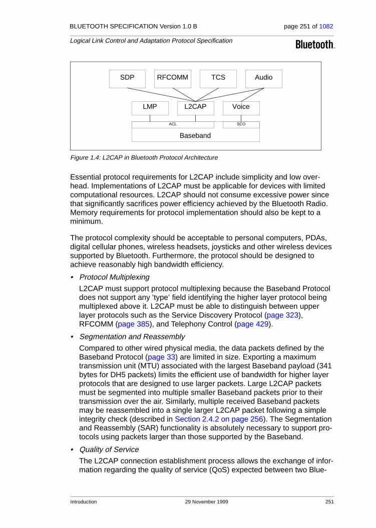
BLUETOOTH SPECIFICATION Version 1.0 B page 251 of 1082
Logical Link Control and Adaptation Protocol Specification
Figure 1.4: L2CAP in Bluetooth Protocol Architecture
Essential protocol requirements for L2CAP include simplicity and low over-head. Implementations of L2CAP must be applicable for devices with limited computational resources. L2CAP should not consume excessive power since that significantly sacrifices power efficiency achieved by the Bluetooth Radio. Memory requirements for protocol implementation should also be kept to a minimum.
The protocol complexity should be acceptable to personal computers, PDAs, digital cellular phones, wireless headsets, joysticks and other wireless devices supported by Bluetooth. Furthermore, the protocol should be designed to achieve reasonably high bandwidth efficiency.
• Protocol Multiplexing
L2CAP must support protocol multiplexing because the Baseband Protocol does not support any ’type’ field identifying the higher layer protocol being multiplexed above it. L2CAP must be able to distinguish between upper layer protocols such as the Service Discovery Protocol (page 323), RFCOMM (page 385), and Telephony Control (page 429).
• Segmentation and Reassembly
Compared to other wired physical media, the data packets defined by the Baseband Protocol (page 33) are limited in size. Exporting a maximum transmission unit (MTU) associated with the largest Baseband payload (341 bytes for DH5 packets) limits the efficient use of bandwidth for higher layer protocols that are designed to use larger packets. Large L2CAP packets must be segmented into multiple smaller Baseband packets prior to their transmission over the air. Similarly, multiple received Baseband packets may be reassembled into a single larger L2CAP packet following a simple integrity check (described in Section 2.4.2 on page 256). The Segmentation and Reassembly (SAR) functionality is absolutely necessary to support pro-tocols using packets larger than those supported by the Baseband.
• Quality of Service
The L2CAP connection establishment process allows the exchange of infor-mation regarding the quality of service (QoS) expected between two Blue-
SDP RFCOMM
L2CAPLMP Voice
ACL SCO
Audio
Baseband
TCS
Introduction 29 November 1999 251

BLUETOOTH SPECIFICATION Version 1.0 B page 252 of 1082
Logical Link Control and Adaptation Protocol Specification
tooth units. Each L2CAP implementation must monitor the resources used by the protocol and ensure that QoS contracts are honoured.
• Groups
Many protocols include the concept of a group of addresses. The Baseband Protocol supports the concept of a piconet, a group of devices synchro-nously hopping together using the same clock. The L2CAP group abstrac-tion permits implementations to efficiently map protocol groups on to piconets. Without a group abstraction, higher level protocols would need to be exposed to the Baseband Protocol and Link Manager functionality in order to manage groups efficiently.
1.2 ASSUMPTIONS
The protocol is designed based on the following assumptions:
1. The ACL link between two units is set up using the Link Manager Protocol (page 185). The Baseband provides orderly delivery of data packets, although there might be individual packet corruption and duplicates. No more than 1 ACL link exists between any two devices.
2. The Baseband always provides the impression of full-duplex communication channels. This does not imply that all L2CAP communications are bi-direc-tional. Multicasts and unidirectional traffic (e.g., video) do not require duplex channels.
3. L2CAP provides a reliable channel using the mechanisms available at the Baseband layer. The Baseband always performs data integrity checks when requested and resends data until it has been successfully acknowledged or a timeout occurs. Because acknowledgements may be lost, timeouts may occur even after the data has been successfully sent. The Baseband proto-col uses a 1-bit sequence number that removes duplicates. Note that the use of Baseband broadcast packets is prohibited if reliability is required since all broadcasts start the first segment of an L2CAP packet with the same sequence bit.
1.3 SCOPE
The following features are outside the scope of L2CAP’s responsibilities:
• L2CAP does not transport audio designated for SCO links.
• L2CAP does not enforce a reliable channel or ensure data integrity, that is, L2CAP performs no retransmissions or checksum calculations.
• L2CAP does not support a reliable multicast channel. See Section 4.2.
• L2CAP does not support the concept of a global group name.
252 29 November 1999 Introduction

BLUETOOTH SPECIFICATION Version 1.0 B page 253 of 1082
Logical Link Control and Adaptation Protocol Specification
2 GENERAL OPERATION
The Logical Link Control and Adaptation Protocol (L2CAP) is based around the concept of ’channels’. Each one of the end-points of an L2CAP channel is referred to by a channel identifier.
2.1 CHANNEL IDENTIFIERS
Channel identifiers (CIDs) are local names representing a logical channel end-point on the device. Identifiers from 0x0001 to 0x003F are reserved for specific L2CAP functions. The null identifier (0x0000) is defined as an illegal identifier and must never be used as a destination end-point. Implementations are free to manage the remaining CIDs in a manner best suited for that particular imple-mentation, with the provision that the same CID is not reused as a local L2CAP channel endpoint for multiple simultaneous L2CAP channels between a local device and some remote device. Table 2.1 summarizes the definition and parti-tioning of the CID name space.
CID assignment is relative to a particular device and a device can assign CIDs independently from other devices (unless it needs to use any of the reserved CIDs shown in the table below). Thus, even if the same CID value has been assigned to (remote) channel endpoints by several remote devices connected to a single local device, the local device can still uniquely associate each remote CID with a different device.
2.2 OPERATION BETWEEN DEVICES
Figure 2.1 on page 254 illustrates the use of CIDs in a communication between corresponding peer L2CAP entities in separate devices. The connection-oriented data channels represent a connection between two devices, where a CID identifies each endpoint of the channel. The connectionless channels restrict data flow to a single direction. These channels are used to support a channel ’group’ where the CID on the source represents one or more remote devices. There are also a number of CIDs reserved for special purposes. The signalling channel is one example of a reserved channel. This channel is used to create and establish connection-oriented data channels and to negotiate changes in the characteristics of these channels. Support for a signalling chan-
CID Description
0x0000 Null identifier
0x0001 Signalling channel
0x0002 Connectionless reception channel
0x0003-0x003F Reserved
0x0040-0xFFFF Dynamically allocated
Table 2.1: CID Definitions
General Operation 29 November 1999 253

BLUETOOTH SPECIFICATION Version 1.0 B page 254 of 1082
Logical Link Control and Adaptation Protocol Specification
nel within an L2CAP entity is mandatory. Another CID is reserved for all incom-ing connectionless data traffic. In the example below, a CID is used to represent a group consisting of device #3 and #4. Traffic sent from this channel ID is directed to the remote channel reserved for connectionless data traffic.
Figure 2.1: Channels between devices
Table 2.2 describes the various channels and their source and destination identifiers. An ’allocated’ channel is created to represent the local endpoint and should be in the range 0x0040 to 0xFFFF. Section 3 on page 258 describes the state machine associated with each connectionless channel. Section 4.1 on page 272 describes the packet format associated with bi-directional channels and Section 4.2 on page 273 describes the packet format associated with uni-directional channels.
2.3 OPERATION BETWEEN LAYERS
L2CAP implementations should follow the general architecture described below. L2CAP implementations must transfer data between higher layer proto-cols and the lower layer protocol. This document lists a number of services that should be exported by any L2CAP implementation. Each implementation must also support a set of signalling commands for use between L2CAP implemen-tations. L2CAP implementations should also be prepared to accept certain types of events from lower layers and generate events to upper layers. How these events are passed between layers is an implementation-dependent pro-cess.
Channel Type Local CID Remote CID
Connection-oriented Dynamically allocated Dynamically allocated
Connectionless data Dynamically allocated 0x0002 (fixed)
Signalling 0x0001 (fixed) 0x0001 (fixed)
Table 2.2: Types of Channel Identifiers
L2CAPEntity
L2CAPEntity
Device #1
L2CAPEntity
Device #2
L2CAPEntity
Device #3
L2CAPEntity
Device #4
CID
CID
CID
Connection-orienteddata channel
Connectionlessdata channel
Signalingchannel
CID
CID
CID CID
CID
CID
254 29 November 1999 General Operation

BLUETOOTH SPECIFICATION Version 1.0 B page 255 of 1082
Logical Link Control and Adaptation Protocol Specification
Figure 2.2: L2CAP Architecture
2.4 SEGMENTATION AND REASSEMBLY
Segmentation and reassembly (SAR) operations are used to improve effi-ciency by supporting a maximum transmission unit (MTU) size larger than the largest Baseband packet. This reduces overhead by spreading the network and transport packets used by higher layer protocols over several Baseband packets. All L2CAP packets may be segmented for transfer over Baseband packets. The protocol does not perform any segmentation and reassembly operations but the packet format supports adaptation to smaller physical frame sizes. An L2CAP implementation exposes the outgoing (i.e., the remote host’s receiving) MTU and segments higher layer packets into ’chunks’ that can be passed to the Link Manager via the Host Controller Interface (HCI), whenever one exists. On the receiving side, an L2CAP implementation receives ’chunks’ from the HCI and reassembles those chunks into L2CAP packets using infor-mation provided through the HCI and from the packet header.
Figure 2.3: L2CAP SAR Variables
Segmentation and Reassembly is implemented using very little overhead in Baseband packets. The two L_CH bits defined in the first byte of Baseband
Lower Layer
L2CAP Layer
Higher Layer
Request IndicationConfirm Response
Response IndicationRequest Confirm
L2CAP Layer
Higher Layer Protocol Layer
L2CAP MTU
HCI Max Buffer
Baseband Protocol Layer
Link Manager
General Operation 29 November 1999 255
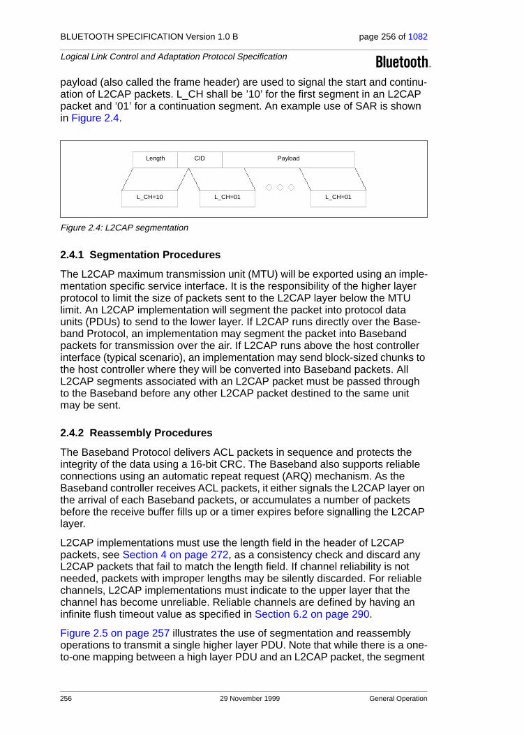
BLUETOOTH SPECIFICATION Version 1.0 B page 256 of 1082
Logical Link Control and Adaptation Protocol Specification
payload (also called the frame header) are used to signal the start and continu-ation of L2CAP packets. L_CH shall be ’10’ for the first segment in an L2CAP packet and ’01’ for a continuation segment. An example use of SAR is shown in Figure 2.4.
Figure 2.4: L2CAP segmentation
2.4.1 Segmentation Procedures
The L2CAP maximum transmission unit (MTU) will be exported using an imple-mentation specific service interface. It is the responsibility of the higher layer protocol to limit the size of packets sent to the L2CAP layer below the MTU limit. An L2CAP implementation will segment the packet into protocol data units (PDUs) to send to the lower layer. If L2CAP runs directly over the Base-band Protocol, an implementation may segment the packet into Baseband packets for transmission over the air. If L2CAP runs above the host controller interface (typical scenario), an implementation may send block-sized chunks to the host controller where they will be converted into Baseband packets. All L2CAP segments associated with an L2CAP packet must be passed through to the Baseband before any other L2CAP packet destined to the same unit may be sent.
2.4.2 Reassembly Procedures
The Baseband Protocol delivers ACL packets in sequence and protects the integrity of the data using a 16-bit CRC. The Baseband also supports reliable connections using an automatic repeat request (ARQ) mechanism. As the Baseband controller receives ACL packets, it either signals the L2CAP layer on the arrival of each Baseband packets, or accumulates a number of packets before the receive buffer fills up or a timer expires before signalling the L2CAP layer.
L2CAP implementations must use the length field in the header of L2CAP packets, see Section 4 on page 272, as a consistency check and discard any L2CAP packets that fail to match the length field. If channel reliability is not needed, packets with improper lengths may be silently discarded. For reliable channels, L2CAP implementations must indicate to the upper layer that the channel has become unreliable. Reliable channels are defined by having an infinite flush timeout value as specified in Section 6.2 on page 290.
Figure 2.5 on page 257 illustrates the use of segmentation and reassembly operations to transmit a single higher layer PDU. Note that while there is a one-to-one mapping between a high layer PDU and an L2CAP packet, the segment
PayloadLength
L_CH=10 L_CH=01 L_CH=01
CID
256 29 November 1999 General Operation

BLUETOOTH SPECIFICATION Version 1.0 B page 257 of 1082
Logical Link Control and Adaptation Protocol Specification
size used by the segmentation and reassembly routines is left to the implemen-tation and may differ from the sender to the receiver.
Figure 2.5: Segmentation and Reassembly Services in a unit with an HCI1
L2
CA
P P
ayl
oa
d
L2
CA
P
Fill
L2
CA
P h
ea
de
rin
form
atio
n to
cre
ate
L2C
AP
pack
et
HC
I-U
SB
Ho
st
So
ftw
are
CID
HC
I d
ata
pa
ylo
ad
Fla
gs=
Sta
rtC
on
ne
ctio
n H
an
dle
Le
ng
th
HC
I d
ata
pa
ylo
ad
Fla
gs=
Co
nti
nu
e
HC
I d
ata
pay
loa
dF
lag
s=C
on
tin
ue
Ra
dio
mo
du
latio
n a
nd
tra
nsm
issi
on
Se
gm
ent
L2
CA
P p
ack
et
into
the
pay
loa
d o
fm
any
HC
I d
ata
pa
cke
ts.
Tra
nsfe
r p
ack
ets
to
US
B d
rive
r
US
BD
riv
er
US
B 1
US
B 2
US
B 3
US
B 4
US
B 5
US
B p
Se
nd U
SB
pa
cke
ts o
ver
bus
US
B H
ard
wa
re b
us
US
BD
riv
er
US
B 1
US
B 2
US
B 3
US
B 4
US
B 5
US
B p
Re
ceiv
e U
SB
pa
cke
ts.
Em
bed
ded
So
ftw
are
HC
I n
HC
I 2
HC
I 1
Re
-ass
em
ble
&b
uff
er
pack
ets
HC
I-U
SB
Air
1 A
ir 2
Air
3A
ir 4
Air
qA
sse
mb
le 1
,3 &
5sl
ot
pa
cke
t ty
pe
s a
sa
pp
rop
riat
e
Lin
k M
an
ag
er
Lin
k C
on
tro
lle
rC
ont
inu
eC
ont
inu
eC
ont
inu
eC
ont
inu
e
Co
ntin
ue
Co
ntin
ue
Sta
rt
Sta
rt
HC
I n
HC
I 2
HC
I 1
Co
ntin
ue
Co
ntin
ue
Sta
rt
HC
I
Len
gth
Len
gth
Co
nn
ecti
on
Ha
nd
le
Co
nn
ecti
on
Ha
nd
le
Le
ng
th
General Operation 29 November 1999 257

BLUETOOTH SPECIFICATION Version 1.0 B page 258 of 1082
Logical Link Control and Adaptation Protocol Specification
3 STATE MACHINE
This section describes the L2CAP connection-oriented channel state machine. The section defines the states, the events causing state transitions, and the actions to be performed in response to events. This state machine is only perti-nent to bi-directional CIDs and is not representative of the signalling channel or the uni-directional channel.
Figure 3.1: L2CAP Layer Interactions
Figure 3.1 illustrates the events and actions performed by an implementation of the L2CAP layer. Client and Server simply represent the initiator of the request and the acceptor of the request respectively. An application-level Client would both initiate and accept requests. The naming convention is as follows. The interface between two layers (vertical interface) uses the prefix of the lower layer offering the service to the higher layer, e.g., L2CA. The interface between two entities of the same layer (horizontal interface) uses the prefix of the proto-col (adding a P to the layer identification), e.g., L2CAP. Events coming from above are called Requests (Req) and the corresponding replies are called Confirms (Cfm). Events coming from below are called Indications (Ind) and the corresponding replies are called Responses (Rsp). Responses requiring fur-ther processing are called Pending (Pnd). The notation for Confirms and Responses assumes positive replies. Negative replies are denoted by a ’Neg’ suffix such as L2CAP_ConnectCfmNeg.
While Requests for an action always result in a corresponding Confirmation (for the successful or unsuccessful satisfaction of the action), Indications do not always result into corresponding Responses. The latter is especially true, if the Indications are informative about locally triggered events, e.g., seeing the
1. For simplicity, the stripping of any additional HCI and USB specific information fields prior to the creation of the baseband packets (Air_1, Air_2, etc.) is not shown in the figure.
L2CAP Layer
Upper Protocol Layer
Lower Protocol (LP) Layer
Upper Protocol Layer
L2CAP Layer
Lower Protocol (LP) Layer
L2CA_Request
Client
L2CA_Confirm
LP_Request LP_Confirm
L2CA_Response
LP_IndicationLP_Response
L2CA_Indication
Server
L2CAP_Request
L2CAP_Response
258 29 November 1999 State Machine

BLUETOOTH SPECIFICATION Version 1.0 B page 259 of 1082
Logical Link Control and Adaptation Protocol Specification
LP_QoSViolationInd in Section 3.1.1 on page 259, or L2CA_TimeOutInd in Section 3.2.4 on page 264.
Figure 3.2: MSC of Layer Interactions
Figure 3.2 uses a message sequence chart (MSC) to illustrate the normal sequence of events. The two outer vertical lines represent the L2CA interface on the initiator (the device issuing a request) and the acceptor (the device responding to the initiator’s request). Request commands at the L2CA inter-face result in Requests defined by the protocol. When the protocol communi-cates the request to the acceptor, the remote L2CA entity presents the upper protocol with an Indication. When the acceptor’s upper protocol responds, the response is packaged by the protocol and communicated back the to initiator. The result is passed back to the initiator’s upper protocol using a Confirm mes-sage.
3.1 EVENTS
Events are all incoming messages to the L2CA layer along with timeouts. Events are partitioned into five categories: Indications and Confirms from lower layers, Requests and Responses from higher layers, data from peers, signal Requests and Responses from peers, and events caused by timer expirations.
3.1.1 Lower-Layer Protocol (LP) to L2CAP events
• LP_ConnectCfm
Confirms the request (see LP_ConnectReq in Section 3.2.1) to establish a lower layer (Baseband) connection. This includes passing the authentication challenge if authentication is required to establish the physical link.
• LP_ConnectCfmNeg
Confirms the failure of the request (see LP_ConnectReq in Section 3.2.1) to establish a lower layer (Baseband) connection failed. This could be because
L2CAP_Request
initiator acceptor
L2CAP_Response
L2CA_Request
L2CA_Indication
L2CA_Response
L2CA_Confirm
TIME
LP LPL2CA L2CA
State Machine 29 November 1999 259
BLUETOOTH SPECIFICATION Version 1.0 B page 260 of 1082
Logical Link Control and Adaptation Protocol Specification
the device could not be contacted, refused the request, or the LMP authenti-cation challenge failed.
• LP_ConnectInd
Indicates the lower protocol has successfully established connection. In the case of the Baseband, this will be an ACL link. An L2CAP entity may use to information to keep track of what physical links exist.
• LP_DisconnectInd
Indicates the lower protocol (Baseband) has been shut down by LMP com-mands or a timeout event.
• LP_QoSCfm
Confirms the request (see LP_QoSReq in Section 3.2.1) for a given quality of service.
• LP_QoSCfmNeg
Confirms the failure of the request (see LP_QoSReq in Section 3.2.1) for a given quality of service.
• LP_QoSViolationInd
Indicates the lower protocol has detected a violation of the QoS agreement specified in the previous LP_QoSReq (see Section 3.2.1).
3.1.2 L2CAP to L2CAP Signalling events
L2CAP to L2CAP signalling events are generated by each L2CAP entity follow-ing the exchange of the corresponding L2CAP signalling PDUs, see Section 5. L2CAP signalling PDUs, like any other L2CAP PDUs, are received from a lower layer via a lower protocol indication event. For simplicity of the presenta-tion, we avoid a detailed description of this process, and we assume that sig-nalling events are exchanged directly between the L2CAP peer entities as shown in Figure 3.1 on page 258.
• L2CAP_ConnectReq
A Connection Request packet has been received.
• L2CAP_ConnectRsp
A Connection Response packet has been received with a positive result indicating that the connection has been established.
• L2CAP_ConnectRspPnd
A Connection Response packet has been received indicating the remote endpoint has received the request and is processing it.
• L2CAP_ConnectRspNeg
A Connection Response packet has been received, indicating that the con-nection could not be established.
• L2CAP_ConfigReq
260 29 November 1999 State Machine

BLUETOOTH SPECIFICATION Version 1.0 B page 261 of 1082
Logical Link Control and Adaptation Protocol Specification
A Configuration Request packet has been received indicating the remote endpoint wishes to engage in negotiations concerning channel parameters.
• L2CAP_ConfigRsp
A Configuration Response packet has been received indicating the remote endpoint agrees with all the parameters being negotiated.
• L2CAP_ConfigRspNeg
A Configuration Response packet has been received indicating the remote endpoint does not agree to the parameters received in the response packet.
• L2CAP_DisconnectReq
A Disconnection Request packet has been received and the channel must initiate the disconnection process. Following the completion of an L2CAP channel disconnection process, an L2CAP entity should return the corre-sponding local CID to the pool of ’unassigned’ CIDs.
• L2CAP_DisconnectRsp
A Disconnection Response packet has been received. Following the receipt of this signal, the receiving L2CAP entity may return the corresponding local CID to the pool of unassigned CIDs. There is no corresponding negative response because the Disconnect Request must succeed.
3.1.3 L2CAP to L2CAP Data events
• L2CAP_Data
A Data packet has been received.
3.1.4 Upper-Layer to L2CAP events
• L2CA_ConnectReq
Request from upper layer for the creation of a channel to a remote device.
• L2CA_ConnectRsp
Response from upper layer to the indication of a connection request from a remote device (see L2CA_ConnectInd in Section 3.2.4).
• L2CA_ConnectRspNeg
Negative response (rejection) from upper layer to the indication of a connec-tion request from a remote device (see L2CA_ConnectInd in Section 3.2.4).
• L2CA_ConfigReq
Request from upper layer to (re)configure the channel.
• L2CA_ConfigRsp
Response from upper layer to the indication of a (re) configuration request (see L2CA_ConfigInd in Section 3.2.4).
• L2CA_ConfigRspNeg
State Machine 29 November 1999 261

BLUETOOTH SPECIFICATION Version 1.0 B page 262 of 1082
Logical Link Control and Adaptation Protocol Specification
A negative response from upper layer to the indication of a (re) configuration request (see L2CA_ConfigInd in Section 3.2.4).
• L2CA_DisconnectReq
Request from upper layer for the immediate disconnection of a channel.
• L2CA_DisconnectRsp
Response from upper layer to the indication of a disconnection request (see L2CA_DisconnectInd in Section 3.2.4). There is no corresponding negative response, the disconnect indication must always be accepted.
• L2CA_DataRead
Request from upper layer for the transfer of received data from L2CAP entity to upper layer.
• L2CA_DataWrite
Request from upper layer for the transfer of data from the upper layer to L2CAP entity for transmission over an open channel.
3.1.5 Timer events
• RTX
The Response Timeout eXpired (RTX) timer is used to terminate the chan-nel when the remote endpoint is unresponsive to signalling requests. This timer is started when a signalling request (see Section 5 on page 275) is sent to the remote device. This timer is disabled when the response is received. If the initial timer expires, a duplicate Request message may be sent or the channel identified in the request may be disconnected. If a dupli-cate Request message is sent, the RTX timeout value must be reset to a new value at least double the previous value.
Implementations have the responsibility to decide on the maximum number of Request retransmissions performed at the L2CAP level before discon-necting the channel. The decision should be based on the flush timeout of the signalling link. The longer the flush timeout, the more retransmissions may be performed at the physical layer and the reliability of the channel improves, requiring fewer retransmissions at the L2CAP level. For example, if the flush timeout is infinite, no retransmissions should be performed at the L2CAP level.
The value of this timer is implementation-dependent but the minimum initial value is 1 second and the maximum initial value is 60 seconds. One RTX timer MUST exist for each outstanding signalling request, including each Echo Request. The timer disappears on the final expiration, when the response is received, or the physical link is lost. The maximum elapsed time between the initial start of this timer and the initiation of channel disconnec-tion (if no response is received) is 60 seconds.
• ERTX
The Extended Response Timeout eXpired (ERTX) timer is used in place of the RTX timer when it is suspected the remote endpoint is performing addi-
262 29 November 1999 State Machine

BLUETOOTH SPECIFICATION Version 1.0 B page 263 of 1082
Logical Link Control and Adaptation Protocol Specification
tional processing of a request signal. This timer is started when the remote endpoint responds that a request is pending, e.g., when an L2CAP_ConnectRspPnd event is received. This timer is disabled when the formal response is received or the physical link is lost. If the initial timer expires, a duplicate Request may be sent or the channel may be discon-nected. If a duplicate Request is sent, the particular ERTX timer disappears, replaced by a new RTX timer and the whole timing procedure restarts as described previously for the RTX timer.
The value of this timer is implementation-dependent but the minimum initial value is 60 seconds and the maximum initial value is 300 seconds. Similar to RTX, there MUST be at least one ERTX timer for each outstanding request that received a Pending response. There should be at most one (RTX or ERTX) associated with each outstanding request. The maximum elapsed time between the initial start of this timer and the initiation of channel discon-nection (if no response is received) is 300 seconds.
3.2 ACTIONS
Actions are partitioned into five categories: Confirms and Indications to higher layers, Request and Responses to lower layers, Requests and Responses to peers, data transmission to peers, and setting timers.
3.2.1 L2CAP to Lower Layer actions
• LP_ConnectReq
L2CAP requests the lower protocol to create a connection. If a physical link to the remote device does not exist, this message must be sent to the lower protocol to establish the physical connection. Since no more than a single ACL link between two devices is assumed, see Section 1.2 on page 252, additional L2CAP channels between these two devices must share the same baseband ACL link.Following the processing of the request, the lower layer returns with an LP_ConnectCfm or an LP_ConnectCfmNeg to indicate whether the request has been satisfied or not, respectively.
• LP_QoSReq
L2CAP requests the lower protocol to accommodate a particular QoS parameter set. Following the processing of the request, the lower layer returns with an LP_QoSCfm or an LP_QoSCfmNeg to indicate whether the request has been satisfied or not, respectively
• LP_ConnectRsp
A positive response accepting the previous connection indication request (see LP_ConnectInd in Section 3.1.1).
• LP_ConnectRspNeg
A negative response denying the previous connection indication request (see LP_ConnectInd in Section 3.1.1).
State Machine 29 November 1999 263

BLUETOOTH SPECIFICATION Version 1.0 B page 264 of 1082
Logical Link Control and Adaptation Protocol Specification
3.2.2 L2CAP to L2CAP Signalling actions
This section contains the same names identified in Section 3.1.2 except the actions refer to the transmission, rather than reception, of these messages.
3.2.3 L2CAP to L2CAP Data actions
This section is the counterpart of Section 3.1.3. Data transmission is the action performed here.
3.2.4 L2CAP to Upper Layer actions
• L2CA_ConnectInd
Indicates a Connection Request has been received from a remote device (see L2CA_ConnectReq in Section 3.1.4).
• L2CA_ConnectCfm
Confirms that a Connection Request has been accepted (see (L2CAP_ConnectReq in Section 3.1.4) following the receipt of a Connection message from the remote device.
• L2CA_ConnectCfmNeg
Negative confirmation (failure) of a Connection Request (see L2CA_ConnectReq in Section 3.1.4). An RTX timer expiration (see Section 3.1.5 and L2CA_TimeOutInd below) for an outstanding Connect Request can substitute for a negative Connect Response and result in this action.
• L2CA_ConnectPnd
Confirms that a Connection Response (pending) has been received from the remote device.
• L2CA_ConfigInd
Indicates a Configuration Request has been received from a remote device.
• L2CA_ConfigCfm
Confirms that a Configuration Request has been accepted (see L2CA_ConfigReq in Section 3.1.4) following the receipt of a Configuration Response from the remote device.
• L2CA_ConfigCfmNeg
Negative confirmation (failure) of a Configuration Request (see L2CA_ConfigReq in Section 3.1.4). An RTX timer expiration (see Section 3.1.5 and L2CA_TimeOutInd below) for an outstanding Connect Request can substitute for a negative Connect Response and result in this action.
264 29 November 1999 State Machine

BLUETOOTH SPECIFICATION Version 1.0 B page 265 of 1082
Logical Link Control and Adaptation Protocol Specification
• L2CA_DisconnectInd
Indicates a Disconnection Request has been received from a remote device or the remote device has been disconnected because it has failed to respond to a signalling request. See Section 3.1.5
• L2CA_DisconnectCfm
Confirms that a Disconnect Request has been processed by the remote device (see L2CA_DisconnectReq in Section 3.1.4) following the receipt of a Disconnection Response from the remote device. An RTX timer expiration (see Section 3.1.5 and L2CA_TimeOutInd below) for an outstanding Discon-nect Request can substitute for a Disconnect Response and result in this action. Upon receiving this event the upper layer knows the L2CAP channel has been terminated. There is no corresponding negative confirm.
• L2CA_TimeOutInd
Indicates that a RTX or ERTX timer has expired. This indication will occur an implementation-dependant number of times before the L2CAP implementa-tion will give up and send a L2CA_DisconnectInd.
• L2CA_QoSViolationInd
Indicates that the quality of service agreement has been violated.
3.3 CHANNEL OPERATIONAL STATES• CLOSED
In this state, there is no channel associated with this CID. This is the only state when a link level connection (Baseband) may not exist. Link discon-nection forces all other states into the CLOSED state.
• W4_L2CAP_CONNECT_RSP
In this state, the CID represents a local end-point and an L2CAP_ConnectReq message has been sent referencing this endpoint and it is now waiting for the corresponding L2CAP_ConnectRsp message.
• W4_L2CA_CONNECT_RSP
In this state, the remote end-point exists and an L2CAP_ConnectReq has been received by the local L2CAP entity. An L2CA_ConnectInd has been sent to the upper layer and the part of the local L2CAP entity processing the received L2CAP_ConnectReq waits for the corresponding response. The response may require a security check to be performed.
• CONFIG
In this state, the connection has been established but both sides are still negotiating the channel parameters. The Configuration state may also be entered when the channel parameters are being renegotiated. Prior to enter-ing the CONFIG state, all outgoing data traffic should be suspended since the traffic parameters of the data traffic are to be renegotiated. Incoming data traffic must be accepted until the remote channel endpoint has entered the CONFIG state.
State Machine 29 November 1999 265

BLUETOOTH SPECIFICATION Version 1.0 B page 266 of 1082
Logical Link Control and Adaptation Protocol Specification
In the CONFIG state, both sides must issue L2CAP_ConfigReq messages – if only defaults are being used, a null message should be sent, see Section 5.4 on page 280. If a large amount of parameters need to be negotiated, multiple messages may be sent to avoid any MTU limitations and negotiate incrementally – see Section 6 on page 289 for more details.
Moving from the CONFIG state to the OPEN state requires both sides to be ready. An L2CAP entity is ready when it has received a positive response to its final request and it has positively responded to the final request from the remote device.
• OPEN
In this state, the connection has been established and configured, and data flow may proceed.
• W4_L2CAP_DISCONNECT_RSP
In this state, the connection is shutting down and an L2CAP_DisconnectReq message has been sent. This state is now waiting for the corresponding response.
• W4_L2CA_DISCONNECT_RSP
In this state, the connection on the remote endpoint is shutting down and an L2CAP_DisconnectReq message has been received. An L2CA_DisconnectInd has been sent to the upper layer to notify the owner of the CID that the remote endpoint is being closed. This state is now waiting for the corresponding response from the upper layer before responding to the remote endpoint.
3.4 MAPPING EVENTS TO ACTIONS
Table 3.1 defines the actions taken in response to events that occur in a partic-ular state. Events that are not listed in the table, nor have actions marked N/C (for no change), are assumed to be errors and silently discarded.
Data input and output events are only defined for the Open and Configuration states. Data may not be received during the initial Configuration state, but may be received when the Configuration state is re-entered due to a reconfiguration process. Data received during any other state should be silently discarded.
266 29 November 1999 State Machine

BLUETOOTH SPECIFICATION Version 1.0 B page 267 of 1082
Logical Link Control and Adaptation Protocol Specification
Event Current State Action New State
LP_ConnectCfm CLOSEDFlag physical link as up and initiate the L2CAP connec-tion.
CLOSED
LP_ConnectCfmNeg CLOSED
Flag physical link as down and fail any outstanding service connection requests by sending an L2CA_ConnectCfmNeg message to the upper layer.
CLOSED
LP_ConnectInd CLOSED Flag link as up. CLOSED
LP_DisconnectInd CLOSED Flag link as down. CLOSED
LP_DisconnectIndAny except CLOSED
Send upper layer L2CA_DisconnectInd message.
CLOSED
LP_QoSViolationInd Any but OPEN Discard N/C
LP_QoSViolationInd OPEN
Send upper layer L2CA_QoSViolationInd message. If service level is guaranteed, terminate the channel.
OPEN or W4_L2CA_DISCONNECT_RSP
L2CAP_ConnectReq
CLOSED. (CID dynamically allo-cated from free pool.)
Send upper layer L2CA_ConnectInd. Option-ally: Send peer L2CAP_ConnectRspPnd
W4_L2CA_CONNECT_RSP
L2CAP_ConnectRspW4_L2CAP_CONNECT_RSP
Send upper layer L2CA_ConnectCfm mes-sage. Disable RTX timer.
CONFIG
L2CAP_ConnectRspPnd
W4_L2CAP_CONNECT_RSP
Send upper layer L2CA_ConnectPnd mes-sage. Disable RTX timer and start ERTX timer.
N/C
L2CAP_ConnectRspNeg
W4_L2CAP_CONNECT_RSP
Send upper layer L2CA_ConnectCfmNeg message. Return CID to free pool. Disable RTX/ERTX timers.
CLOSED
L2CAP_ConfigReq CLOSEDSend peer L2CAP_ConfigRspNeg message.
N/C
L2CAP_ConfigReq CONFIGSend upper layer L2CA_ConfigInd message.
N/C
Table 3.1: L2CAP Channel State Machine
State Machine 29 November 1999 267
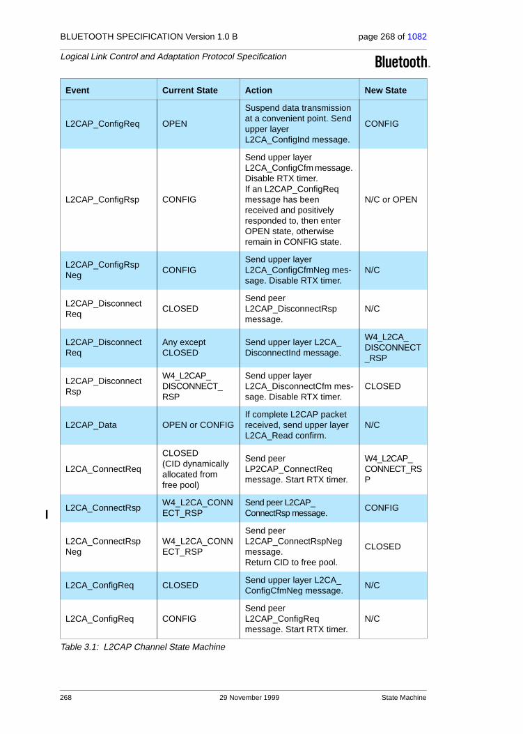
BLUETOOTH SPECIFICATION Version 1.0 B page 268 of 1082
Logical Link Control and Adaptation Protocol Specification
L2CAP_ConfigReq OPEN
Suspend data transmission at a convenient point. Send upper layer L2CA_ConfigInd message.
CONFIG
L2CAP_ConfigRsp CONFIG
Send upper layer L2CA_ConfigCfm message. Disable RTX timer. If an L2CAP_ConfigReq message has been received and positively responded to, then enter OPEN state, otherwise remain in CONFIG state.
N/C or OPEN
L2CAP_ConfigRspNeg
CONFIGSend upper layer L2CA_ConfigCfmNeg mes-sage. Disable RTX timer.
N/C
L2CAP_DisconnectReq
CLOSEDSend peer L2CAP_DisconnectRsp message.
N/C
L2CAP_DisconnectReq
Any except CLOSED
Send upper layer L2CA_DisconnectInd message.
W4_L2CA_DISCONNECT_RSP
L2CAP_DisconnectRsp
W4_L2CAP_DISCONNECT_RSP
Send upper layer L2CA_DisconnectCfm mes-sage. Disable RTX timer.
CLOSED
L2CAP_Data OPEN or CONFIGIf complete L2CAP packet received, send upper layer L2CA_Read confirm.
N/C
L2CA_ConnectReq
CLOSED (CID dynamically allocated from free pool)
Send peer LP2CAP_ConnectReq message. Start RTX timer.
W4_L2CAP_CONNECT_RSP
L2CA_ConnectRspW4_L2CA_CONNECT_RSP
Send peer L2CAP_ConnectRsp message.
CONFIG
L2CA_ConnectRspNeg
W4_L2CA_CONNECT_RSP
Send peer L2CAP_ConnectRspNeg message. Return CID to free pool.
CLOSED
L2CA_ConfigReq CLOSEDSend upper layer L2CA_ConfigCfmNeg message.
N/C
L2CA_ConfigReq CONFIGSend peer L2CAP_ConfigReq message. Start RTX timer.
N/C
Event Current State Action New State
Table 3.1: L2CAP Channel State Machine
268 29 November 1999 State Machine

BLUETOOTH SPECIFICATION Version 1.0 B page 269 of 1082
Logical Link Control and Adaptation Protocol Specification
Figure 3.3 illustrates a simplified state machine and typical transition path taken by an initiator and acceptor. The state machine shows what events cause state transitions and what actions are also taken while the transitions occur. Not all the events listed in Table 3.1 are included in the simplified State Machine to avoid cluttering the figure.
L2CA_ConfigReq OPEN
Suspend data transmission at a convenient point. Send peer L2CAP_ConfigReq message. Start RTX timer.
CONFIG
L2CA_ConfigRsp CONFIG
Send peer L2CAP_ConfigRsp message. If all outstanding L2CAP_ConfigReq mes-sages have received posi-tive responses then move in OPEN state. Otherwise, remain in CONFIG state.
N/C or OPEN
L2CA_ConfigRspNeg CONFIGSend peer L2CAP_ConfigRspNeg message.
N/C
L2CA_DisconnectReq
OPEN or CONFIGSend peer L2CAP_DisconnectReq message. Start RTX timer.
W4_L2CAP_DISCONNECT_RSP
L2CA_DisconnectRspW4_L2CA_DISCONNECT_RSP
Send peer L2CAP_DisconnectRsp message. Return CID to free pool.
CLOSED
L2CA_DataRead OPENIf payload complete, trans-fer payload to InBuffer.
OPEN
L2CA_DataWrite OPENSend peer L2CAP_Data message.
OPEN
Timer_RTX Any
Send upper layer L2CA_TimeOutInd message. If final expiration, return CID to free pool else re-send Request.
CLOSED
Timer_ERTX Any
Send upper layer L2CA_TimeOutInd message. If final expiration, return CID to free pool else re-send Request.
CLOSED
Event Current State Action New State
Table 3.1: L2CAP Channel State Machine
State Machine 29 November 1999 269
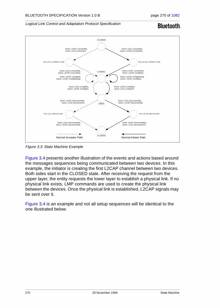
BLUETOOTH SPECIFICATION Version 1.0 B page 270 of 1082
Logical Link Control and Adaptation Protocol Specification
Figure 3.3: State Machine Example
Figure 3.4 presents another illustration of the events and actions based around the messages sequences being communicated between two devices. In this example, the initiator is creating the first L2CAP channel between two devices. Both sides start in the CLOSED state. After receiving the request from the upper layer, the entity requests the lower layer to establish a physical link. If no physical link exists, LMP commands are used to create the physical link between the devices. Once the physical link is established, L2CAP signals may be sent over it.
Figure 3.4 is an example and not all setup sequences will be identical to the one illustrated below.
CLOSED
W4_L2CA_CONNECT_RSP W4_L2CAP_CONNECT_RSP
Event: L2CA_ConnectReqAction: L2CAP_ConnectReq
Event: L2CAP_ConnectReqAction: L2CA_ConnectInd
W4_L2CA_DISCON_RSP
OPEN
CLOSED
Event:L2CAP_ConnectRspAction: L2CAP_ConfigReq
Event: L2CA_DisconnectReqAction: L2CAP_DisconnectReq
Event: L2CAP_DisconnectReqAction: L2CA_DisconnectInd
W4_L2CAP_DISCON_RSP
Event: L2CAP_DisconnectRspAction: L2CA_DisconnectCfm
CONFIG
Event: L2CAP_ConfigRspAction: L2CA_ConfigCfm
Event: L2CAP_ConfigRspNegAction: L2CAP_ConfigReq
Event: L2CA_ConnectRspAction: L2CAP_ConnectRsp
Event: L2CA_ConfigReqAction: L2CAP_ConfigRsp
Event: L2CA_DisconnectRspAction: L2CAP_DisconnectRsp
Normal Intiator PathNormal Acceptor Path
Event: L2CAP_ConfigReqAction: L2CAP_ConfigRspNeg
270 29 November 1999 State Machine

BLUETOOTH SPECIFICATION Version 1.0 B page 271 of 1082
Logical Link Control and Adaptation Protocol Specification
Figure 3.4: Message Sequence Chart of Basic Operation
L2CAP_ConnectRsp
L2CAP_ConnectReq
initiator target
L2CAP_ConfigReq
L2CAP_ConfigRsp
L2CAP_DisconnectReq
L2CAP_DisconnectRsp
[CLOSED] [CLOSED]
L2CA_ConnectReq
[W4_L2CAP_ConnectRsp]
[CONFIG]
[W4_L2CA_ConnectRsp]
[CONFIG]
[OPEN]
[OPEN]
L2CA_DisconnectReq
[W4_L2CAP_DisconnectRsp] [W4_L2CA_DisconnectRsp]
[CLOSED] [CLOSED]
Data
LMPLP_ConnectReq
LP_ConnectCfm
LP_ConnectInd
LP_ConnectRsp
L2CAP_ConfigReq
L2CAP_ConfigRsp
Data
Data
L2CA_DisconnectCfm
L2CA_ConnectInd
L2CA_ConnectRsp
L2CA_ConnectCfm
L2CA_DisconnectInd
L2CA_DisconnectRsp
LP LP
L2CA_ConfigReqL2CA_ConfigInd
L2CA_ConfigRsp
L2CA_ConfigCfm
L2CA_ConfigInd L2CA_ConfigReqL2CA_ConfigRsp
L2CA_ConfigCfm
State Machine 29 November 1999 271

BLUETOOTH SPECIFICATION Version 1.0 B page 272 of 1082
Logical Link Control and Adaptation Protocol Specification
4 DATA PACKET FORMAT
L2CAP is packet-based but follows a communication model based on chan-nels. A channel represents a data flow between L2CAP entities in remote devices. Channels may be connection-oriented or connectionless. All packet fields use Little Endian byte order.
4.1 CONNECTION-ORIENTED CHANNEL
Figure 4.1 illustrates the format of the L2CAP packet (also referred to as the L2CAP PDU) within a connection-oriented channel.
Figure 4.1: L2CAP Packet (field sizes in bits)
The fields shown are:
• Length: 2 octets (16 bits)
Length indicates the size of information payload in bytes, excluding the length of the L2CAP header. The length of an information payload can be up to 65535 bytes. The Length field serves as a simple integrity check of the reassembled L2CAP packet on the receiving end.
• Channel ID: 2 octets
The channel ID identifies the destination channel endpoint of the packet. The scope of the channel ID is relative to the device the packet is being sent to.
• Information: 0 to 65535 octets
This contains the payload received from the upper layer protocol (outgoing packet), or delivered to the upper layer protocol (incoming packet). The min-imum supported MTU for connection-oriented packets (MTUcno) is negoti-ated during channel configuration (see Section 6.1 on page 289). The minimum supported MTU for the signalling packet (MTUsig) is 48 bytes (see Section 5 on page 275).
Information (payload)Channel IDLength
L2CAP Header
16 16LSB MSB
272 29 November 1999 Data Packet Format

BLUETOOTH SPECIFICATION Version 1.0 B page 273 of 1082
Logical Link Control and Adaptation Protocol Specification
4.2 CONNECTIONLESS DATA CHANNEL
In addition to connection-oriented channels, L2CAP also exports the concept of a group-oriented channel. Data sent to the ’group’ channel is sent to all mem-bers of the group in a best-effort manner. Groups have no quality of service associated with them. Group channels are unreliable; L2CAP makes no guar-antee that data sent to the group successfully reaches all members of the group. If reliable group transmission is required, it must be implemented at a higher layer.
Transmissions to a group must be non-exclusively sent to all members of that group. The local device cannot be a member of the group, and higher layer protocols are expected to loopback any data traffic being sent to the local device. Non-exclusive implies non-group members may receive group trans-missions and higher level (or link level) encryption can be used to support pri-vate communication.
Figure 4.2: Connectionless Packet
The fields shown are:
• Length: 2 octets
Length indicates the size of information payload plus the PSM field in bytes, excluding the length of the L2CAP header.
• Channel ID: 2 octets
Channel ID (0x0002) reserved for connectionless traffic.
• Protocol/Service Multiplexer (PSM): 2 octets (minimum)
The PSM field is based on the ISO 3309 extension mechanism for address fields. All content of the PSM field, referred to as the PSM value, must be ODD, that is, the least significant bit of the least significant octet must be ’1’. Also, all PSM values must be assigned such that the least significant bit of the most significant octet equals ’0’. This allows the PSM field to be extended beyond 16 bits. The PSM value definitions are specific to L2CAP and assigned by the Bluetooth SIG. For more information on the PSM field see Section 5.2 on page 278.
Length (0x0002)
PSM
Information (cont.)
LSB MSBbyte0 byte1 byte2 byte3
Information (payload)
Channel ID
Data Packet Format 29 November 1999 273

BLUETOOTH SPECIFICATION Version 1.0 B page 274 of 1082
Logical Link Control and Adaptation Protocol Specification
• Information: 0 to 65533 octets
The payload information to be distributed to all members of the group. Implementations must support a minimum connectionless MTU (MTUcnl) of 670 octets, unless explicitly agreed upon otherwise, e.g., for single opera-tion devices that are built to comply to a specific Bluetooth profile that dic-tates the use of a specific MTU for connectionless traffic that is less than MTUcnl.
The L2CAP group service interface provides basic group management mecha-nisms including creating a group, adding members to a group, and removing members from a group. There are no pre-defined groups such as ‘all radios in range’.
274 29 November 1999 Data Packet Format

BLUETOOTH SPECIFICATION Version 1.0 B page 275 of 1082
Logical Link Control and Adaptation Protocol Specification
5 SIGNALLING
This section describes the signalling commands passed between two L2CAP entities on remote devices. All signalling commands are sent to CID 0x0001. The L2CAP implementation must be able to determine the Bluetooth address (BD_ADDR) of the device that sent the commands. Figure 5.1 illustrates the general format of all L2CAP packets containing signalling commands. Multiple commands may be sent in a single (L2CAP) packet and packets are sent to CID 0x0001. MTU Commands take the form of Requests and Responses. All L2CAP implementations must support the reception of signalling packets whose MTU (MTUsig) does not exceed 48 bytes. L2CAP implementations should not use signalling packets beyond this size without first testing whether the implementation can support larger signalling packets.
Figure 5.1: Signalling Command Packet Format
Figure 5.2 displays the general format of all signalling commands.
Figure 5.2: Command format
The fields shown are:
• Code: 1 octet
The Code field is one octet long and identifies the type of command. When a packet is received with an unknown Code field, a Command Reject packet (defined in Section 5.1 on page 277) is sent in response.Up-to-date values of assigned Codes are specified in the latest Bluetooth ’Assigned Numbers’ document (page 1009). Table 5.1 on page 276 lists the codes defined by this document. All codes are specified with the most signif-icant bit in the left-most position.
Length 0x0001
Command #1
LSB MSBbyte0 byte1 byte2 byte3
Command #2
LengthCode Identifier
data
LSB MSBbyte0 byte1 byte2 byte3
Signalling 29 November 1999 275

BLUETOOTH SPECIFICATION Version 1.0 B page 276 of 1082
Logical Link Control and Adaptation Protocol Specification
• Identifier: 1 octet
The Identifier field is one octet long and helps matching a request with the reply. The requesting device sets this field and the responding device uses the same value in its response. A different Identifier must be used for each original command. Identifiers should not be recycled until a period of 360 seconds has elapsed from the initial transmission of the command using the identifier. On the expiration of a RTX or ERTX timer, the same identifier should be used if a duplicate Request is re-sent as stated in Section 3.1.5 on page 262. A device receiving a duplicate request should reply with a duplicate response. A command response with an invalid identifier is silently discarded. Signalling identifier 0x0000 is defined to be an illegal identifier and shall never be used in any command.
• Length: 2 octets
The Length field is two octets long and indicates the size in octets of the data field of the command only, i.e., it does not cover the Code, Identifier, and Length fields.
• Data: 0 or more octets
The Data field is variable in length and discovered using the Length field. The Code field determines the format of the Data field.
Code Description
0x00 RESERVED
0x01 Command reject
0x02 Connection request
0x03 Connection response
0x04 Configure request
0x05 Configure response
0x06 Disconnection request
0x07 Disconnection response
0x08 Echo request
0x09 Echo response
0x0A Information request
0x0B Information response
Table 5.1: Signalling Command Codes
276 29 November 1999 Signalling

BLUETOOTH SPECIFICATION Version 1.0 B page 277 of 1082
Logical Link Control and Adaptation Protocol Specification
5.1 COMMAND REJECT (CODE 0x01)
A Command Reject packet is sent in response to a command packet with an unknown command code or when sending the corresponding Response is inappropriate. Figure 5.3 displays the format of the packet. The Identifier should match the Identifier of the packet containing the unidentified code field. Implementations must always send these packets in response to unidentified signalling packets.
When multiple commands are included in an L2CAP packet and the packet exceeds the MTU of the receiver, a single Command Reject packet is sent in response. The identifier should match the first Request command in the L2CAP packet. If only Responses are recognized, the packet shall be silently discarded.
Figure 5.3: Command Reject Packet
• Length = 0x0002 or more octets
• Reason: 2 octets
The Reason field describes why the Request packet was rejected.
• Data: 0 or more octets
The length and content of the Data field depends on the Reason code. If the Reason code is 0x0000, “Command not understood”, no Data field is used. If the Reason code is 0x0001, “Signalling MTU Exceeded”, the 2-octet Data field represents the maximum signalling MTU the sender of this packet can accept.If a command refers to an invalid channel then the Reason code 0x0002 will be returned. Typically a channel is invalid because it does not exist. A 4-octet data field on the command reject will contain the local (first) and remote (second) channel endpoints (relative to the sender of the Command Reject) of the disputed channel. The latter endpoints are obtained from the corresponding rejected command. If the rejected command contains only one of the channel endpoints, the other one is replaced by the null CID 0x0000.
Reason value Description
0x0000 Command not understood
0x0001 Signalling MTU exceeded
0x0002 Invalid CID in request
Other Reserved
Table 5.2: Reason Code Descriptions
Code=0x01 LengthIdentifier
LSB MSBbyte0 byte1 byte2 byte3
Reason Data (optional)
Signalling 29 November 1999 277

BLUETOOTH SPECIFICATION Version 1.0 B page 278 of 1082
Logical Link Control and Adaptation Protocol Specification
5.2 CONNECTION REQUEST (CODE 0x02)
Connection request packets are sent to create a channel between two devices. The channel connection must be established before configuration may begin. Figure 5.4 illustrates a Connection Request packet.
Figure 5.4: Connection Request Packet
• Length = 0x0004 or more octets
• Protocol/Service Multiplexor (PSM): 2 octets (minimum)
The PSM field is two octets (minimum) in length. The structure of the PSM field is based on the ISO 3309 extension mechanism for address fields. All PSM values must be ODD, that is, the least significant bit of the least signifi-cant octet must be ’1’. Also, all PSM values must be assigned such that the least significant bit of the most significant octet equals ’0’. This allows the PSM field to be extended beyond 16 bits. PSM values are separated into two ranges. Values in the first range are assigned by the Bluetooth SIG and indicate protocols. The second range of values are dynamically allocated and used in conjunction with the Service Discovery Protocol (SDP). The dynamically assigned values may be used to support multiple implementa-tions of a particular protocol, e.g., RFCOMM, residing on top of L2CAP or for prototyping an experimental protocol.
Reason value Data Length Data value
0x0000 0 octets N/A
0x0001 2 octets Actual MTU
0x0002 4 octets Requested CID
Table 5.3: Reason Data values
PSM value Description
0x0001 Service Discovery Protocol
0x0003 RFCOMM
0x0005 Telephony Control Protocol
<0x1000 RESERVED
[0x1001-0xFFFF] DYNAMICALLY ASSIGNED
Table 5.4: Defined PSM Values
PSM
Code=0x02 LengthIdentifier
LSB MSBbyte0 byte1 byte2 byte3
Source CID
278 29 November 1999 Signalling
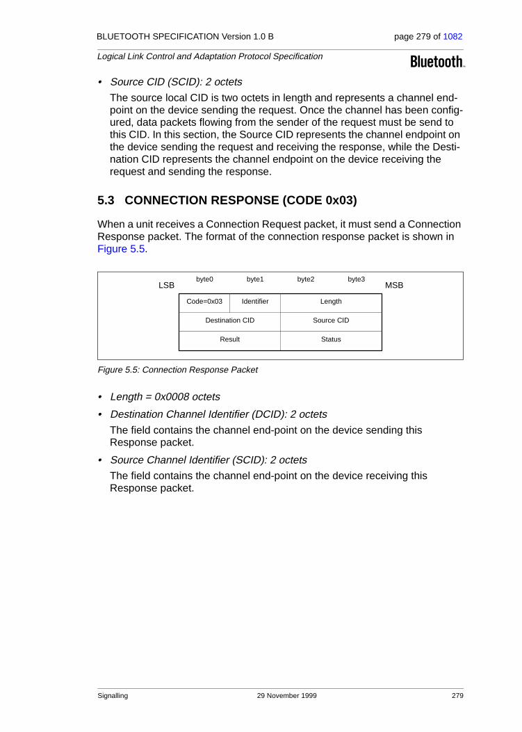
BLUETOOTH SPECIFICATION Version 1.0 B page 279 of 1082
Logical Link Control and Adaptation Protocol Specification
• Source CID (SCID): 2 octets
The source local CID is two octets in length and represents a channel end-point on the device sending the request. Once the channel has been config-ured, data packets flowing from the sender of the request must be send to this CID. In this section, the Source CID represents the channel endpoint on the device sending the request and receiving the response, while the Desti-nation CID represents the channel endpoint on the device receiving the request and sending the response.
5.3 CONNECTION RESPONSE (CODE 0x03)
When a unit receives a Connection Request packet, it must send a Connection Response packet. The format of the connection response packet is shown in Figure 5.5.
Figure 5.5: Connection Response Packet
• Length = 0x0008 octets
• Destination Channel Identifier (DCID): 2 octets
The field contains the channel end-point on the device sending this Response packet.
• Source Channel Identifier (SCID): 2 octets
The field contains the channel end-point on the device receiving this Response packet.
Destination CID
Code=0x03 LengthIdentifier
LSB MSBbyte0 byte1 byte2 byte3
Source CID
Result Status
Signalling 29 November 1999 279

BLUETOOTH SPECIFICATION Version 1.0 B page 280 of 1082
Logical Link Control and Adaptation Protocol Specification
• Result: 2 octets
The result field indicates the outcome of the connection request. The result value of 0x0000 indicates success while a non-zero value indicates the con-nection request failed. A logical channel is established on the receipt of a successful result. Table 5.5 defines values for this field. If the result field is not zero, the DCID and SCID fields should be ignored.
• Status: 2 octets
Only defined for Result = Pending. Indicates the status of the connection.
5.4 CONFIGURATION REQUEST (CODE 0x04)
Configuration Request packets are sent to establish an initial logical link trans-mission contract between two L2CAP entities and also to re-negotiate this con-tract whenever appropriate. During a re-negotiation session, all data traffic on the channel should be suspended pending the outcome of the negotiation. Each configuration parameter in a Configuration Request is related exclusively either with the outgoing or the incoming data traffic but not both of them. In Section 6 on page 289, the various configuration parameters and their relation to the outgoing or incoming data traffic are presented. If an L2CAP entity receives a Configuration Request while it is waiting for a response it must not block sending the Configuration Response, otherwise the configuration pro-cess may deadlock.
If no parameters need to be negotiated, no options need to be inserted and the C-bit should be cleared. L2CAP entities in remote devices MUST negotiate all parameters defined in this document whenever the default values are not
Value Description
0x0000 Connection successful.
0x0001 Connection pending
0x0002 Connection refused – PSM not supported.
0x0003 Connection refused – security block.
0x0004 Connection refused – no resources available.
Other Reserved.
Table 5.5: Result values
Value Description
0x0000 No further information available
0x0001 Authentication pending
0x0002 Authorization pending
Other Reserved
Table 5.6: Status values
280 29 November 1999 Signalling

BLUETOOTH SPECIFICATION Version 1.0 B page 281 of 1082
Logical Link Control and Adaptation Protocol Specification
acceptable. Any missing configuration parameters are assumed to have their most recently (mutually) explicitly or implicitly accepted values. Event if all default values are acceptable, a Configuration Request packet with no options MUST be sent. Implicitly accepted values are any default values for the config-uration parameters specified in this document that have not been explicitly negotiated for the specific channel under configuration.
Each configuration parameter is one-directional and relative to the direction implied by the sender of a Configuration Request. If a device needs to estab-lish the value of a configuration parameter in the opposite direction than the one implied by a Configuration Request, a new Configuration Request with the desired value of the configuration parameter in it needs to be sent in the direc-tion opposite the one used for the original Connection Request.
The decision on the amount of time (or messages) spent arbitrating the chan-nel parameters before terminating the negotiation is left to the implementation but it shall not last more than 120 seconds.
Figure 5.6 defines the format of the Configuration Request packet.
Figure 5.6: Configuration Request Packet
• Length = 0x0004 or more octets
• Destination CID (DCID): 2 octets
The field contains the channel end-point on the device receiving this Request packet.
• Flags: 2 octets
Figure 5.7 display the two-octet Flags field. Note the most significant bit is shown on the left.
Figure 5.7: Configuration Request Flags field format
C – more configuration requests will follow when set to 1. This flag indicates that the remote device should not enter OPEN state after agreeing to these parameters because more parameter negotiations are being sent. Segment-
Flags
Code=0x04 LengthIdentifier
LSB MSBbyte0 byte1 byte2 byte3
Destination CID
Options
MSB LSB
Reserved C
Signalling 29 November 1999 281
BLUETOOTH SPECIFICATION Version 1.0 B page 282 of 1082
Logical Link Control and Adaptation Protocol Specification
ing the Configuration Request packet is necessary if the parameters exceed the MTUsig.
Other flags are reserved and should be cleared. L2CAP implementations should ignore these bits.
• Configuration Options
The list of the parameters and their values to be negotiated. These are defined in Section 6 on page 289. Configuration Requests may contain no options (referred to as an empty or null configuration request) and can be used to request a response. For an empty configuration request the length field is set to 0x0004.
282 29 November 1999 Signalling

BLUETOOTH SPECIFICATION Version 1.0 B page 283 of 1082
Logical Link Control and Adaptation Protocol Specification
5.5 CONFIGURE RESPONSE (CODE 0X05)
Configure Response packets MUST be sent in reply to Configuration Request packets. Each configuration parameter value (if any is present) in a Configura-tion Response reflects an ’adjustment’ to a configuration parameter value that has been sent (or, in case of default values, implied) in the corresponding Con-figuration Request. Thus, for example, if a configuration parameter in a Config-uration Request relates to traffic flowing from device A to device B, the sender of the Configuration Response will only adjust (if needed) this value again for the same traffic flowing from device A to device B. The options sent in the Response depend on the value in the Result field. Figure 5.8 defines the for-mat of the Configuration Response packet.
Figure 5.8: Configuration Response Packet
• Length = 0x0006 or more octets
• Source CID (SCID): 2 octets
The field contains the channel end-point on the device receiving this Response packet. The device receiving the Response must check that the Identifier field matches the same field in the corresponding configuration request command and the SCID matches its local CID paired with the origi-nal DCID.
• Flags: 2 octets
Figure 5.9 displays the two-octet Flags field. Note the most significant bit is shown on the left.
Figure 5.9: Configuration Response Flags field format
C – more configuration responses will follow when set to 1. This flag indi-cates that the parameters included in the response are a partial subset of parameters being sent by the device sending the Response packet.
Other flags are reserved and should be cleared. L2CAP implementations should ignore these bits.
Code=0x05 LengthIdentifier
LSB MSBbyte0 byte1 byte2 byte3
Source CID Flags
Result Config
MSB LSB
Reserved C
Signalling 29 November 1999 283

BLUETOOTH SPECIFICATION Version 1.0 B page 284 of 1082
Logical Link Control and Adaptation Protocol Specification
• Result: 2 octets
The Result field indicates whether or not the Request was acceptable. See Table 5.7 for possible result codes.
• Configuration Options
This field contains the list of parameters being negotiated. These are defined in Section 6 on page 289. On a successful result, these parameters contain the return values for any wild card parameters (see Section 6.3 on page 291) contained in the request.
On an unacceptable parameters failure (Result=0x0001) the rejected parameters should be sent in the response with the values that would have been accepted if sent in the original request. Any missing configuration parameters are assumed to have their most recently (mutually) accepted values and they too can be included in the Configuration Response if need to be changed. Recall that, each configuration parameter is one-directional and relative to the direction implied by the sender of a Configuration Request. Thus, if the sender of the Configuration Response needs to estab-lish the value of a configuration parameter in the opposite direction than the one implied by an original Configuration Request, a new Configuration Request with the desired value of the configuration parameter in it needs to be sent in the direction opposite the one used for the original Connection Request.
On an unknown option failure (Result=0x0003), the option types not under-stood by the recipient of the Request must be included in the Response. Note that hints (defined in Section 6 on page 289), those options in the Request that are skipped if not understood, must not be included in the Response and must not be the sole cause for rejecting the Request.
The decision on the amount of time (or messages) spent arbitrating the channel parameters before terminating the negotiation is left to the imple-mentation.
Result Description
0x0000 Success
0x0001 Failure – unacceptable parameters
0x0002 Failure – rejected (no reason provided)
0x0003 Failure – unknown options
Other RESERVED
Table 5.7: Configuration Response Result codes
284 29 November 1999 Signalling

BLUETOOTH SPECIFICATION Version 1.0 B page 285 of 1082
Logical Link Control and Adaptation Protocol Specification
5.6 DISCONNECTION REQUEST (CODE 0x06)
Terminating an L2CAP channel requires that a disconnection request packet be sent and acknowledged by a disconnection response packet. Disconnection is requested using the signalling channel since all other L2CAP packets sent to the destination channel automatically get passed up to the next protocol layer. Figure 5.10 displays a disconnection packet request. The receiver must ensure both source and destination CIDs match before initiating a connection discon-nection. Once a Disconnection Request is issued, all incoming data in transit on this L2CAP channel will be discarded and any new additional outgoing data is not allowed. Once a disconnection request for a channel has been received, all data queued to be sent out on that channel may be discarded.
Figure 5.10: Disconnection Request Packet
• Length = 0x0004 octets
• Destination CID (DCID): 2 octets
This field specifies the end-point of the channel to be shutdown on the device receiving this request.
• Source CID (SCID): 2 octets
This field specifies the end-point of the channel to be shutdown on the device sending this request.
The SCID and DCID are relative to the sender of this request and must match those of the channel to be disconnected. If the DCID is not recog-nized by the receiver of this message, a CommandReject message with ’invalid CID’ result code must be sent in response. If the receivers finds a DCID match but the SCID fails to find the same match, the request should be silently discarded.
LSB MSBbyte0 byte1 byte2 byte3
Code=0x06
Destination CID
Identifier Length
Source CID
Signalling 29 November 1999 285

BLUETOOTH SPECIFICATION Version 1.0 B page 286 of 1082
Logical Link Control and Adaptation Protocol Specification
5.7 DISCONNECTION RESPONSE (CODE 0x07)
Disconnection responses should be sent in response to each disconnection request.
Figure 5.11: Disconnection Response Packet
• Length = 0x0004 octets
• Destination CID (DCID): 2 octets
This field identifies the channel end-point on the device sending the response.
• Source CID (SCID): 2 octets
This field identifies the channel end-point on the device receiving the response.
The DCID and the SCID (which are relative to the sender of the request), and the Identifier fields must match those of the corresponding disconnec-tion request command. If the CIDs do not match, the response should be silently discarded at the receiver.
5.8 ECHO REQUEST (CODE 0x08)
Echo requests are used to solicit a response from a remote L2CAP entity. These requests may be used for testing the link or passing vendor specific information using the optional data field. L2CAP entities MUST respond to well-formed Echo Request packets with an Echo Response packet. The Data field is optional and implementation-dependent. L2CAP entities should ignore the contents of this field.
Figure 5.12: Echo Request Packet
LSB MSBbyte0 byte1 byte2 byte3
Code=0x07
Destination CID
Identifier Length
Source CID
Code=0x08 LengthIdentifier
LSB MSBbyte0 byte1 byte2 byte3
Data (optional)
286 29 November 1999 Signalling
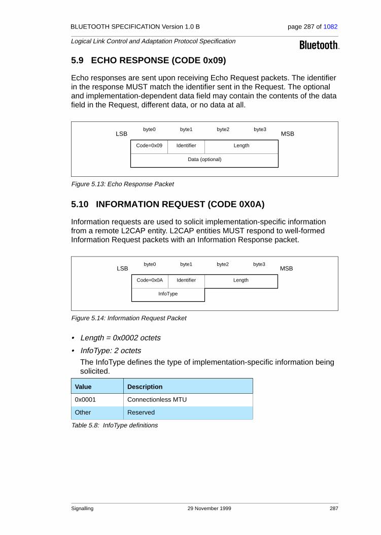
BLUETOOTH SPECIFICATION Version 1.0 B page 287 of 1082
Logical Link Control and Adaptation Protocol Specification
5.9 ECHO RESPONSE (CODE 0x09)
Echo responses are sent upon receiving Echo Request packets. The identifier in the response MUST match the identifier sent in the Request. The optional and implementation-dependent data field may contain the contents of the data field in the Request, different data, or no data at all.
Figure 5.13: Echo Response Packet
5.10 INFORMATION REQUEST (CODE 0X0A)
Information requests are used to solicit implementation-specific information from a remote L2CAP entity. L2CAP entities MUST respond to well-formed Information Request packets with an Information Response packet.
Figure 5.14: Information Request Packet
• Length = 0x0002 octets
• InfoType: 2 octets
The InfoType defines the type of implementation-specific information being solicited.
Value Description
0x0001 Connectionless MTU
Other Reserved
Table 5.8: InfoType definitions
Code=0x09 LengthIdentifier
LSB MSBbyte0 byte1 byte2 byte3
Data (optional)
Code=0x0A LengthIdentifier
LSB MSBbyte0 byte1 byte2 byte3
InfoType
Signalling 29 November 1999 287

BLUETOOTH SPECIFICATION Version 1.0 B page 288 of 1082
Logical Link Control and Adaptation Protocol Specification
5.11 INFORMATION RESPONSE (CODE 0X0B)
Information responses are sent upon receiving Information Request packets. The identifier in the response MUST match the identifier sent in the Request. The optional data field may contain the contents of the data field in the Request, different data, or no data at all.
Figure 5.15: Information Response Packet
• InfoType: 2 octets
Same value sent in the request.
• Result: 2 octets
The Result contains information about the success of the request. If result is "Success", the data field contains the information as specified in Table 5.10. If result is "Not supported", no data should be returned.
• Data: 0 or more octets
The contents of the Data field depends on the InfoType. For the Connection MTU request, the data field contains the remote entity’s 2-octet acceptable connectionless MTU.
Value Description
0x0000 Success
0x0001 Not supported
Other Reserved
Table 5.9: Information Response Result values
InfoType Data Data Length (in octets)
0x0001 Connectionless MTU 2
Table 5.10: Information Response Data fields
Code=0x0B LengthIdentifier
LSB MSBbyte0 byte1 byte2 byte3
Data (optional)
InfoType Result
288 29 November 1999 Signalling

BLUETOOTH SPECIFICATION Version 1.0 B page 289 of 1082
Logical Link Control and Adaptation Protocol Specification
6 CONFIGURATION PARAMETER OPTIONS
Options are a mechanism to extend the ability to negotiate different connection requirements. Options are transmitted in the form of information elements com-prised an option type, an option length, and one or more option data fields. Fig-ure 6.1 illustrates the format of an option.
Figure 6.1: Configuration option format
• Type: 1 octet
The option type field defines the parameters being configured. The most sig-nificant bit of the type determines the action taken if the option is not recog-nized. The semantics assigned to the bit are defined below.
0 - option must be recognized; refuse the configuration request
1 - option is a hint; skip the option and continue processing
• Length: 1 octet
The length field defines the number of octets in the option payload. So an option type with no payload has a length of 0.
• Option data
The contents of this field are dependent on the option type.
6.1 MAXIMUM TRANSMISSION UNIT (MTU)
This option specifies the payload size the sender is capable of accepting. The type is 0x01, and the payload length is 2 bytes, carrying the two-octet MTU size value as the only information element (see Figure 6.2 on page 290).
Since all L2CAP implementations are capable to support a minimum L2CAP packet size, see Section 4 on page 272, MTU is not really a negotiated value but rather an informational parameter to the remote device that the local device can accommodate in this channel an MTU larger than the minimum required. In the unlikely case that the remote device is only willing to send L2CAP packets in this channel that are larger than the MTU announced by the local device, then this Configuration Request will receive a negative response in which the remote device will include the value of MTU that is indented to transmit. In this case, it is implementation specific on whether the local device will continue the configuration process or even maintain this channel.
The remote device in its positive Configuration Response will include the actual MTU to be used on this channel for traffic flowing into the local device which is
byte 0
type length option data
byte 1 byte 2
LSB MSB
byte 3
Configuration Parameter Options 29 November 1999 289

BLUETOOTH SPECIFICATION Version 1.0 B page 290 of 1082
Logical Link Control and Adaptation Protocol Specification
minimum{ MTU in configReq, outgoing MTU capability of remote device }. The MTU to be used on this channel but for the traffic flowing in the opposite direc-tion will be established when the remote device (with respect to this discussion) sends its own Configuration Request as explained in Section 5.4 on page 280.
Figure 6.2: MTU Option Format
• Maximum Transmission Unit (MTU) Size: 2 octets
The MTU field represents the largest L2CAP packet payload, in bytes, that the originator of the Request can accept for that channel. The MTU is asym-metric and the sender of the Request shall specify the MTU it can receive on this channel if it differs from the default value. L2CAP implementations must support a minimum MTU size of 48 bytes. The default value is 672 bytes1.
6.2 FLUSH TIMEOUT OPTION
This option is used to inform the recipient of the amount of time the originator’s link controller / link manager will attempt to successfully transmit an L2CAP segment before giving up and flushing the packet. The type is 0x02 and the payload size is 2 octets.
Figure 6.3: Flush Timeout
• Flush Timeout
This value represents units of time measured in milliseconds. The value of 1 implies no retransmissions at the Baseband level should be performed since the minimum polling interval is 1.25 ms. The value of all 1’s indicates an infi-nite amount of retransmissions. This is also referred to as ’reliable channel’. In this case, the link manager shall continue retransmitting a segment until physical link loss occurs. This is an asymmetric value and the sender of the Request shall specify its flush timeout value if it differs from the default value of 0xFFFF.
1. The default MTU was selected based on the payload carried by two Baseband DH5 pack-ets (2*341=682) minus the Baseband ACL headers (2*2=4) and L2CAP header (6).
0 31
type=0x01 length=2 MTU
0 31
type=0x02 length=2 Flush Timeout
290 29 November 1999 Configuration Parameter Options

BLUETOOTH SPECIFICATION Version 1.0 B page 291 of 1082
Logical Link Control and Adaptation Protocol Specification
6.3 QUALITY OF SERVICE (QOS) OPTION
This option specifies a flow specification (flowSpec) similar to RFC 1363 [1]. If no QoS configuration parameter is negotiated the link should assume the default parameters discussed below. The QoS option is type 0x03.
When included in a Configuration Request, this option describes the outgoing traffic flow from the device sending the request to the device receiving it. When included in a positive Configuration Response, this option describes the incom-ing traffic flow agreement as seen from the device sending the response. When included in a negative Configuration Response, this option describes the pre-ferred incoming traffic flow from the perspective of the device sending the response.
L2CAP implementations are only required to support ’Best Effort’ service, sup-port for any other service type is optional. Best Effort does not require any guarantees. If no QoS option is placed in the request, Best Effort must be assumed. If any QoS guarantees are required then a QoS configuration request must be sent.
The remote device places information that depends on the value of the result field, see Section 5.5 on page 283, in its Configuration Response. If the request was for Guaranteed Service, the response shall include specific values for any wild card parameters (see Token Rate and Token Bucket Size descrip-tions) contained in the request. If the result is “Failure – unacceptable parame-ters”, the response may include a list of outgoing flowspec parameters and parameter values that would make a new Connection Request from the local device acceptable by the remote device. Both explicitly referenced in a Config-uration Request or implied configuration parameters can be included in a Con-figuration Response. Recall that any missing configuration parameters from a Configuration Request are assumed to have their most recently (mutually) accepted values. For both Best effort and Guaranteed service, when the QoS option appears in the Configuration Response, "do not cares" shall be present where they appeared in the Configuration Request.
Figure 6.4: Quality of Service Flow Specification
Flags service type
Delay Variation (microseconds)
Token Rate
Token Bucket Size (bytes)
0 31
Peak Bandwidth (bytes/second)
Latency (microseconds)
0x03 length=22
Configuration Parameter Options 29 November 1999 291
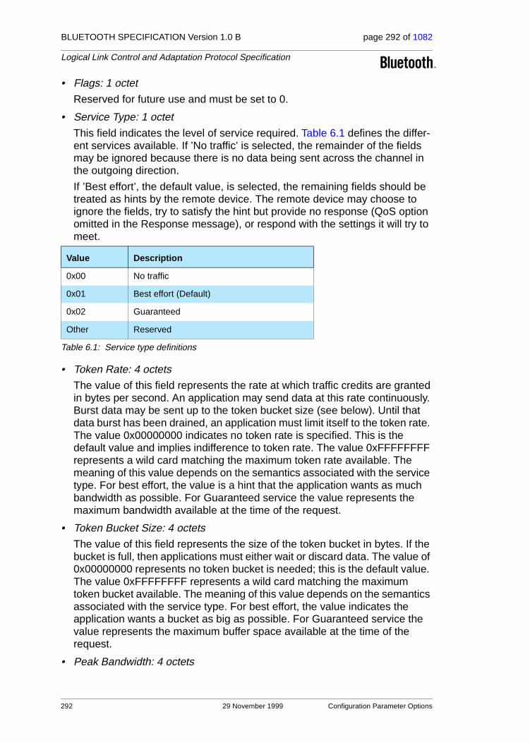
BLUETOOTH SPECIFICATION Version 1.0 B page 292 of 1082
Logical Link Control and Adaptation Protocol Specification
• Flags: 1 octet
Reserved for future use and must be set to 0.
• Service Type: 1 octet
This field indicates the level of service required. Table 6.1 defines the differ-ent services available. If ’No traffic’ is selected, the remainder of the fields may be ignored because there is no data being sent across the channel in the outgoing direction.
If ’Best effort’, the default value, is selected, the remaining fields should be treated as hints by the remote device. The remote device may choose to ignore the fields, try to satisfy the hint but provide no response (QoS option omitted in the Response message), or respond with the settings it will try to meet.
• Token Rate: 4 octets
The value of this field represents the rate at which traffic credits are granted in bytes per second. An application may send data at this rate continuously. Burst data may be sent up to the token bucket size (see below). Until that data burst has been drained, an application must limit itself to the token rate. The value 0x00000000 indicates no token rate is specified. This is the default value and implies indifference to token rate. The value 0xFFFFFFFF represents a wild card matching the maximum token rate available. The meaning of this value depends on the semantics associated with the service type. For best effort, the value is a hint that the application wants as much bandwidth as possible. For Guaranteed service the value represents the maximum bandwidth available at the time of the request.
• Token Bucket Size: 4 octets
The value of this field represents the size of the token bucket in bytes. If the bucket is full, then applications must either wait or discard data. The value of 0x00000000 represents no token bucket is needed; this is the default value. The value 0xFFFFFFFF represents a wild card matching the maximum token bucket available. The meaning of this value depends on the semantics associated with the service type. For best effort, the value indicates the application wants a bucket as big as possible. For Guaranteed service the value represents the maximum buffer space available at the time of the request.
• Peak Bandwidth: 4 octets
Value Description
0x00 No traffic
0x01 Best effort (Default)
0x02 Guaranteed
Other Reserved
Table 6.1: Service type definitions
292 29 November 1999 Configuration Parameter Options

BLUETOOTH SPECIFICATION Version 1.0 B page 293 of 1082
Logical Link Control and Adaptation Protocol Specification
The value of this field, expressed in bytes per second, limits how fast pack-ets may be sent back-to-back from applications. Some intermediate systems can take advantage of this information, resulting in more efficient resource allocation. The value of 0x00000000 states that the maximum bandwidth is unknown, which is the default value.
• Latency: 4 octets
The value of this field represents the maximum acceptable delay between transmission of a bit by the sender and its initial transmission over the air, expressed in microseconds. The precise interpretation of this number depends on the level of guarantee specified in the Class of Service. The value 0xFFFFFFFF represents a do not care and is the default value.
• Delay Variation: 4 octets
The value of this field is the difference, in microseconds, between the maxi-mum and minimum possible delay that a packet will experience. This value is used by applications to determine the amount of buffer space needed at the receiving side in order to restore the original data transmission pattern. The value 0xFFFFFFFF represents a do not care and is the default value.
6.4 CONFIGURATION PROCESS
Negotiating the channel parameters involves three steps:
1. Informing the remote side of the non-default parameters that the local side will accept
2. Having the remote side agreeing or disagreeing to these values (including the default ones); steps (1) and (2) may iterate as needed
3. Repeat steps (1) and (2) for the reverse direction from the (previous) remote side to the (previous) local side.
This process can be abstracted into a Request negotiation path and a Response negotiation path.
6.4.1 Request Path
The Request Path negotiates the incoming MTU, flush timeout, and outgoing flowspec. Table 6.2 defines the configuration options that may be placed in the Configuration Request message and their semantics.
Parameter Description
MTU Incoming MTU information
FlushTO Outgoing flush timeout
OutFlow Outgoing flow information.
Table 6.2: Parameters allowed in Request
Configuration Parameter Options 29 November 1999 293

BLUETOOTH SPECIFICATION Version 1.0 B page 294 of 1082
Logical Link Control and Adaptation Protocol Specification
6.4.2 Response Path
The Response Path negotiates the outgoing MTU (remote side’s incoming MTU), the remote side’s flush timeout, and incoming flowspec (remote side’s outgoing flowspec). If a request-oriented parameter is not present in the Request message (reverts to default value), the remote side may negotiate for a non-default value by including the proposed value in a negative Response message.
6.4.3 Configuration State Machine
The configuration state machine shown below depicts two paths. Before leav-ing the CONFIG state and moving into the OPEN state, both paths must reach closure. The request path requires the local device to receive a positive response to reach closure while the response path requires the local device to send a positive response to reach closure.
Figure 6.5: Configuration State Machine
“Appendix A: Configuration MSCs” on page 318 provides some configuration examples.
Parameter Description
MTU Outgoing MTU information
FlushTO Incoming flush timeout
InFlow Incoming flow information
Table 6.3: Parameters allowed in Response
CONFIG START
Event: L2CA_ConfigReqAction: L2CAP_ConfigReq
Event: L2CAP_ConfigReqAction: L2CA_ConfigInd
Event: L2CAP_ConfigRspAction: L2CA_ConfigCfm
Event: L2CAP_ConfigRspNegAction: L2CA_ConfigCfmNeg
Event: L2CA_ConfigRspAction: L2CAP_ConfigRsp
Request Negotialtion PathResponse negotiation path
Event: L2CA_ConfigRspNegAction: L2CAP_ConfigRspNeg
CONFIG END
REQUEST RECEIVED REQUEST SENT
294 29 November 1999 Configuration Parameter Options

BLUETOOTH SPECIFICATION Version 1.0 B page 295 of 1082
Logical Link Control and Adaptation Protocol Specification
7 SERVICE PRIMITIVES
This section presents an abstract description of the services offered by L2CAP in terms of service primitives and parameters. The service interface is required for testing. The interface is described independently of any platform specific implementation. All data values use Little Endian byte ordering.
7.1 EVENT INDICATION
Description:
The use of this primitive requests a callback when the selected indication Event occurs.
Input Parameters:
Event Type: uint Size: 2 octets
Callback Type: function Size: N/A
Output Parameters:
Result Type: uint Size: 2 octets
Service Input Parameters Output Parameters
EventIndication Event, Callback Result
Value Description
0x00 Reserved
0x01 L2CA_ConnectInd
0x02 L2CA_ConfigInd
0x03 L2CA_DisconnectInd
0x04 L2CA_QoSViolationInd
other Reserved for future use
Event Callback Function Input Parameters
L2CA_ConnectInd BD_ADDR, CID, PSM, Identifier
L2CA_ConfigInd CID, OutMTU, InFlow, InFlushTO
L2CA_DisconnectInd CID
L2CA_QoSViolationInd BD_ADDR
Value Description
0x0000 Event successfully registered
0x0001 Event registration failed
Service Primitives 29 November 1999 295

BLUETOOTH SPECIFICATION Version 1.0 B page 296 of 1082
Logical Link Control and Adaptation Protocol Specification
7.1.1 L2CA_ConnectInd Callback
This callback function includes the parameters for the address of the remote device that issued the connection request, the local CID representing the chan-nel being requested, the Identifier contained in the request, and the PSM value the request is targeting.
7.1.2 L2CA_ConfigInd Callback
This callback function includes the parameters indicating the local CID of the channel the request has been sent to, the outgoing MTU size (maximum packet that can be sent across the channel) and the flowspec describing the characteristics of the incoming data. All other channel parameters are set to their default values if not provided by the remote device.
7.1.3 L2CA_DisconnectInd Callback
This callback function includes the parameter indicating the local CID the request has been sent to.
7.1.4 L2CA_QoSViolationInd Callback
This callback function includes the parameter indicating the address of the remote Bluetooth device where the QoS contract has been violated.
7.2 CONNECT
Description:
This primitive initiates the sending of an L2CA_ConnectReq message and blocks until a corresponding L2CA_ConnectCfm(Neg) or L2CA_TimeOutInd message is received.
The use of this primitive requests the creation of a channel representing a logi-cal connection to a physical address. Input parameters are the target protocol (PSM) and remote device’s 48-bit address (BD_ADDR). Output parameters are the local CID (LCID) allocated by the local L2CAP entity, and Result of the request. If the Result indicates success, the LCID value contains the identifica-tion of the local endpoint. Otherwise the LCID returned should be set to 0. If Result indicates a pending notification, the Status value may contain more information of what processing is delaying the establishment of the connection. Otherwise the Status value should be ignored.
Service Input Parameters Output Parameters
L2CA_ConnectReq PSM, BD_ADDR LCID, Result, Status
296 29 November 1999 Service Primitives

BLUETOOTH SPECIFICATION Version 1.0 B page 297 of 1082
Logical Link Control and Adaptation Protocol Specification
Input Parameters:
PSM Type: uint Size: 2 octets
BD_ADDR Type: unit Size: 6 octets
Output Parameters:
LCID Type: uint Size: 2 octets
Result Type: uint Size: 2 octets
Status Type: uint Size: 2 octets
Value Description
0xXXXX Target PSM provided for the connection
Value Description
0xXXXXXXXXXXXX Unique Bluetooth address of target device
Value Description
0xXXXX Channel ID representing local end-point of the communication channel if Result = 0x0000, otherwise set to 0.
Value Description
0x0000 Connection successful and the CID identifies the local endpoint. Ignore Sta-tus parameter
0x0001 Connection pending. Check Status parameter for more information
0x0002 Connection refused because no service for the PSM has been registered
0x0003 Connection refused because the security architecture on the remote side has denied the request
0xEEEE Connection timeout occurred. This is a result of a timer expiration indication being included in the connection confirm message
Value Description
0x0000 No further information
0x0001 Authentication pending
0x0002 Authorization pending
Service Primitives 29 November 1999 297

BLUETOOTH SPECIFICATION Version 1.0 B page 298 of 1082
Logical Link Control and Adaptation Protocol Specification
7.3 CONNECT RESPONSE
Description:
This primitive represents the L2CA_ConnectRsp.
The use of this primitive issues a response to a connection request event indi-cation. Input parameters are the remote device’s 48-bit address, Identifier sent in the request, local CID, the Response code, and the Status attached to the Response code. The output parameter is the Result of the service request.
This primitive must be called no more than once after receiving the callback indication. This primitive returns once the local L2CAP entity has validated the request. A successful return does indicate the response has been sent over the air interface.
Input Parameters:
BD_ADDR Type: unit Size: 6 octets
Identifier Type: uint Size: 1 octets
LCID Type: uint Size: 2 octets
Response Type: uint Size: 2 octets
Service Input Parameters Output Parameters
L2CA_ConnectRsp BD_ADDR, Identifier, LCID, Response, Status
Result
Value Description
0xXXXXXXXXXXXX Unique Bluetooth address of target device
Value Description
0xXX. This value must match the value received in the L2CA_ConnectInd event described in Section 7.1.1 on page 296
Value Description
0xXXXX Channel ID representing local end-point of the communication channel
Value Description
0x0000 Connection successful
0x0001 Connection pending
0x0002 Connection refused – PSM not supported
0x0003 Connection refused – security block
0x0004 Connection refused – no resources available
0xXXXX Other connection response code
298 29 November 1999 Service Primitives
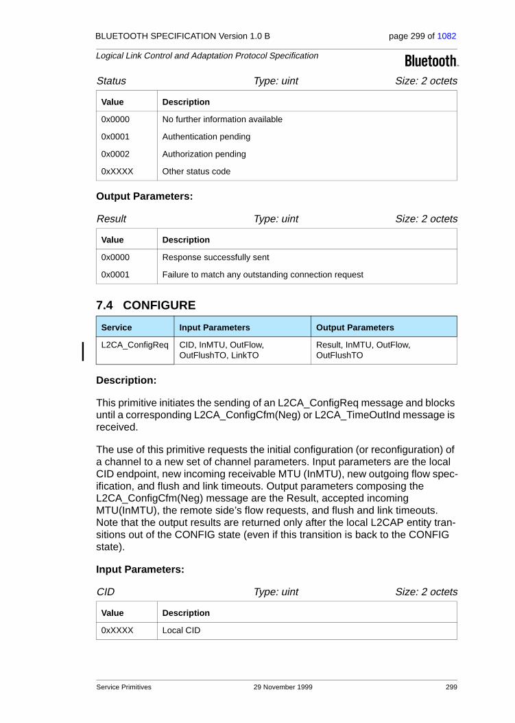
BLUETOOTH SPECIFICATION Version 1.0 B page 299 of 1082
Logical Link Control and Adaptation Protocol Specification
Status Type: uint Size: 2 octets
Output Parameters:
Result Type: uint Size: 2 octets
7.4 CONFIGURE
Description:
This primitive initiates the sending of an L2CA_ConfigReq message and blocks until a corresponding L2CA_ConfigCfm(Neg) or L2CA_TimeOutInd message is received.
The use of this primitive requests the initial configuration (or reconfiguration) of a channel to a new set of channel parameters. Input parameters are the local CID endpoint, new incoming receivable MTU (InMTU), new outgoing flow spec-ification, and flush and link timeouts. Output parameters composing the L2CA_ConfigCfm(Neg) message are the Result, accepted incoming MTU(InMTU), the remote side’s flow requests, and flush and link timeouts. Note that the output results are returned only after the local L2CAP entity tran-sitions out of the CONFIG state (even if this transition is back to the CONFIG state).
Input Parameters:
CID Type: uint Size: 2 octets
Value Description
0x0000 No further information available
0x0001 Authentication pending
0x0002 Authorization pending
0xXXXX Other status code
Value Description
0x0000 Response successfully sent
0x0001 Failure to match any outstanding connection request
Service Input Parameters Output Parameters
L2CA_ConfigReq CID, InMTU, OutFlow, OutFlushTO, LinkTO
Result, InMTU, OutFlow, OutFlushTO
Value Description
0xXXXX Local CID
Service Primitives 29 November 1999 299

BLUETOOTH SPECIFICATION Version 1.0 B page 300 of 1082
Logical Link Control and Adaptation Protocol Specification
InMTU Type: uint Size: 2 octets
OutFlow Type: Flow Size: x octets
OutFlushTO Size 2 octets
LinkTO Size 2 octets
Output Parameters:
Result Size 2 octets
InMTU Size 2 octets
Value Description
0xXXXX Maximum transmission unit this channel can accept
Value Description
flowspec Quality of service parameters dealing with the traffic characteristics of the outgoing data flow
Value Description
0xXXXX Number of milliseconds to wait before an L2CAP packet that cannot be acknowledged at the physical layer is dropped
0x0000 Request to use the existing flush timeout value if one exists, otherwise the default value (0xFFFF) will be used
0x0001 Perform no retransmissions at the Baseband layer
0xFFFF Perform retransmission at the Baseband layer until the link timeout termi-nates the channel
Value Description
0xXXXX Number of milliseconds to wait before terminating an unresponsive link
Value Description
0x0000 Configuration is successful. Parameters contain agreed upon values
0x0001 Failure – invalid CID
0x0002 Failure – unacceptable parameters
0x0003 Failure – signalling MTU exceeded
0x0004 Failure – unknown options
0xEEEE Configuration timeout occurred. This is a result of a timer expiration indica-tion being included in the configuration confirm
Value Description
0xXXXX Maximum transmission unit that the remote unit will send across this channel (maybe less or equal to the InMTU input parameter).
300 29 November 1999 Service Primitives

BLUETOOTH SPECIFICATION Version 1.0 B page 301 of 1082
Logical Link Control and Adaptation Protocol Specification
OutFlow Size 2 octets
OutFlushTO Size 2 octets
7.5 CONFIGURATION RESPONSE
Description:
This primitive represents the L2CAP_ConfigRsp.
The use of this primitive issues a response to a configuration request event indication. Input parameters include the local CID of the endpoint being config-ured, outgoing transmit MTU (which may be equal or less to the OutMTU parameter in the L2CA_ConfigInd event) and the accepted flowspec for incom-ing traffic. The output parameter is the Result value.
Input Parameters:
LCID Type: uint Size: 2 octets
OutMTU Type: uint Size: 2 octets
InFlow Type: Flow Size: x octets
Value Description
FlowSpec Quality of service parameters dealing with the traffic characteristics of the agreed-upon outgoing data flow if Result is successful. Otherwise this rep-resents the requested Quality of Service
Value Description
0xXXXX Number of milliseconds before an L2CAP packet that cannot be acknowl-edged at the physical layer is dropped. This value is informative of the actual value that will be used for outgoing packets. It may be less or equal to the OutFlushTO parameter given as input.
Service Input Parameters Output Parameters
L2CA_ConfigRsp CID, OutMTU, InFlow Result
Value Description
0xXXXX Local channel identifier
Value Description
0xXXXX Maximum transmission unit this channel will send
Value Description
FlowSpec Quality of service parameters dealing with the traffic characteristics of the incoming data flow
Service Primitives 29 November 1999 301

BLUETOOTH SPECIFICATION Version 1.0 B page 302 of 1082
Logical Link Control and Adaptation Protocol Specification
Output Parameters:
Result Size 2 octets
7.6 DISCONNECT
Description:
This primitive represents the L2CAP_DisconnectReq and the returned output parameters represent the corresponding L2CAP_DisconnectRsp or the RTX timer expiration.
The use of this primitive requests the disconnection of the channel. Input parameter is the CID representing the local channel endpoint. Output parame-ter is Result. Result is zero if a L2CAP_DisconnectRsp is received, otherwise a non-zero value is returned. Once disconnection has been requested, no pro-cess will be able to successfully read or write from the CID. Writes in progress should continue to be processed.
Input Parameters:
CID Type: uint Size: 2 octets
Output Parameters:
Result Type: uint Size: 2 octets
Value Description
0x0000 Configuration is successful. Parameters contain agreed upon values
0x0001 Configuration failed – unacceptable parameters
0x0002 Configuration failed – rejected
0x0003 Configuration failed – invalid CID
0x0004 Configuration failed – unknown options
0xXXXX Reserved
Service Input Parameters Output Parameters
L2CA_DisconnectReq CID Result
Value Description
0xXXXX Channel ID representing local end-point of the communication channel
Value Description
0x0000 Disconnection successful. This is a result of the receipt of a disconnection response message
0xEEEE Disconnection timeout occurred.
302 29 November 1999 Service Primitives

BLUETOOTH SPECIFICATION Version 1.0 B page 303 of 1082
Logical Link Control and Adaptation Protocol Specification
7.7 WRITE
Description:
The use of this primitive requests the transfer of data across the channel. If the length of the data exceeds the OutMTU then only the first OutMTU bytes are sent This command may be used for both connection-oriented and connection-less traffic.
Input Parameters:
CID Type: uint Size: 2 octets
Length Type: uint Size: 2 octets
OutBuffer Type: pointer Size: N/A
Output Parameters:
Size Type: uint Size: 2 octets
Result Type: uint Size: 2 octets
Service Input Parameters Output Parameters
L2CA_DataWrite CID, Length, OutBuffer Size, Result
Value Description
0xXXXX Channel ID representing local end-point of the communication channel
Value Description
0xXXXX Size, in bytes, of the buffer where data to be transmitted are stored
Value Description
N/A Address of the input buffer used to store the message
Value Description
0xXXXX The number of bytes transferred
Value Description
0x0000 Successful write
0x0001 Error – Flush timeout expired
0x0002 Error – Link termination (perhaps this should be left to the indication)
Service Primitives 29 November 1999 303
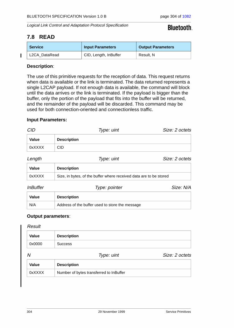
BLUETOOTH SPECIFICATION Version 1.0 B page 304 of 1082
Logical Link Control and Adaptation Protocol Specification
7.8 READ
Description:
The use of this primitive requests for the reception of data. This request returns when data is available or the link is terminated. The data returned represents a single L2CAP payload. If not enough data is available, the command will block until the data arrives or the link is terminated. If the payload is bigger than the buffer, only the portion of the payload that fits into the buffer will be returned, and the remainder of the payload will be discarded. This command may be used for both connection-oriented and connectionless traffic.
Input Parameters:
CID Type: uint Size: 2 octets
Length Type: uint Size: 2 octets
InBuffer Type: pointer Size: N/A
Output parameters:
Result
N Type: uint Size: 2 octets
Service Input Parameters Output Parameters
L2CA_DataRead CID, Length, InBuffer Result, N
Value Description
0xXXXX CID
Value Description
0xXXXX Size, in bytes, of the buffer where received data are to be stored
Value Description
N/A Address of the buffer used to store the message
Value Description
0x0000 Success
Value Description
0xXXXX Number of bytes transferred to InBuffer
304 29 November 1999 Service Primitives
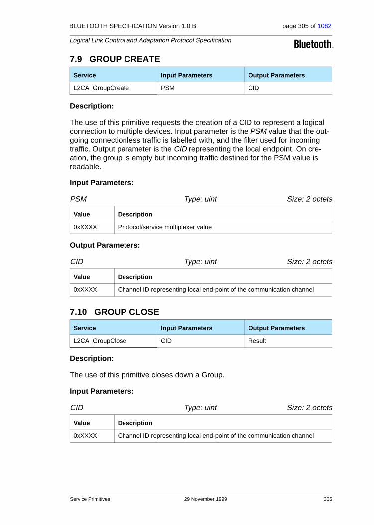
BLUETOOTH SPECIFICATION Version 1.0 B page 305 of 1082
Logical Link Control and Adaptation Protocol Specification
7.9 GROUP CREATE
Description:
The use of this primitive requests the creation of a CID to represent a logical connection to multiple devices. Input parameter is the PSM value that the out-going connectionless traffic is labelled with, and the filter used for incoming traffic. Output parameter is the CID representing the local endpoint. On cre-ation, the group is empty but incoming traffic destined for the PSM value is readable.
Input Parameters:
PSM Type: uint Size: 2 octets
Output Parameters:
CID Type: uint Size: 2 octets
7.10 GROUP CLOSE
Description:
The use of this primitive closes down a Group.
Input Parameters:
CID Type: uint Size: 2 octets
Service Input Parameters Output Parameters
L2CA_GroupCreate PSM CID
Value Description
0xXXXX Protocol/service multiplexer value
Value Description
0xXXXX Channel ID representing local end-point of the communication channel
Service Input Parameters Output Parameters
L2CA_GroupClose CID Result
Value Description
0xXXXX Channel ID representing local end-point of the communication channel
Service Primitives 29 November 1999 305
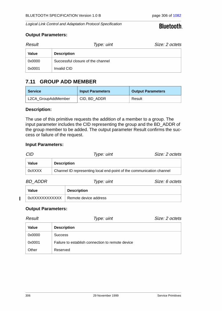
BLUETOOTH SPECIFICATION Version 1.0 B page 306 of 1082
Logical Link Control and Adaptation Protocol Specification
Output Parameters:
Result Type: uint Size: 2 octets
7.11 GROUP ADD MEMBER
Description:
The use of this primitive requests the addition of a member to a group. The input parameter includes the CID representing the group and the BD_ADDR of the group member to be added. The output parameter Result confirms the suc-cess or failure of the request.
Input Parameters:
CID Type: uint Size: 2 octets
BD_ADDR Type: uint Size: 6 octets
Output Parameters:
Result Type: uint Size: 2 octets
Value Description
0x0000 Successful closure of the channel
0x0001 Invalid CID
Service Input Parameters Output Parameters
L2CA_GroupAddMember CID, BD_ADDR Result
Value Description
0xXXXX Channel ID representing local end-point of the communication channel
Value Description
0xXXXXXXXXXXXX Remote device address
Value Description
0x0000 Success
0x0001 Failure to establish connection to remote device
Other Reserved
306 29 November 1999 Service Primitives

BLUETOOTH SPECIFICATION Version 1.0 B page 307 of 1082
Logical Link Control and Adaptation Protocol Specification
7.12 GROUP REMOVE MEMBER
Description:
The use of this primitive requests the removal of a member from a group. The input parameters include the CID representing the group and BD_ADDR of the group member to be removed. The output parameter Result confirms the suc-cess or failure of the request.
Input Parameters:
CID Type: uint Size: 2 octets
BD_ADDR Type: uint Size: 6 octets
Output Parameters:
Result Type: uint Size: 2 octets
Service Input Parameters Output Parameters
L2CA_GroupRemoveMember CID, BD_ADDR Result
Value Description
0xXXXX Channel ID representing local end-point of the communication channel
Value Description
0xXXXXXXXXXXXX Unique Bluetooth address device to be removed
Value Description
0x0000 Success
0x0001 Failure – device not a member of the group
Other Reserved
Service Primitives 29 November 1999 307
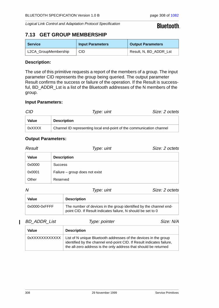
BLUETOOTH SPECIFICATION Version 1.0 B page 308 of 1082
Logical Link Control and Adaptation Protocol Specification
7.13 GET GROUP MEMBERSHIP
Description:
The use of this primitive requests a report of the members of a group. The input parameter CID represents the group being queried. The output parameter Result confirms the success or failure of the operation. If the Result is success-ful, BD_ADDR_Lst is a list of the Bluetooth addresses of the N members of the group.
Input Parameters:
CID Type: uint Size: 2 octets
Output Parameters:
Result Type: uint Size: 2 octets
N Type: uint Size: 2 octets
BD_ADDR_List Type: pointer Size: N/A
Service Input Parameters Output Parameters
L2CA_GroupMembership CID Result, N, BD_ADDR_Lst
Value Description
0xXXXX Channel ID representing local end-point of the communication channel
Value Description
0x0000 Success
0x0001 Failure – group does not exist
Other Reserved
Value Description
0x0000-0xFFFF The number of devices in the group identified by the channel end-point CID. If Result indicates failure, N should be set to 0
Value Description
0xXXXXXXXXXXXX List of N unique Bluetooth addresses of the devices in the group identified by the channel end-point CID. If Result indicates failure, the all-zero address is the only address that should be returned
308 29 November 1999 Service Primitives

BLUETOOTH SPECIFICATION Version 1.0 B page 309 of 1082
Logical Link Control and Adaptation Protocol Specification
7.14 PING
Description:
This primitive represents the initiation of an L2CA_EchoReq command and the reception of the corresponding L2CA_EchoRsp command.
Input Parameters:
BD_ADDR Type: uint Size: 6 octets
ECHO_DATA Type: pointer Size: N/A
Length Type: uint Size: 2 octets
Output Parameters:
Result Type: uint Size: 2 octets
ECHO_DATA Type: pointer Size: N/A
Size Type: uint Size: 2 octets
Service Input Parameters Output Parameters
L2CA_Ping BD_ADDR, ECHO_DATA, Length Result, ECHO_DATA, Size
Value Description
0xXXXXXXXXXXXX Unique Bluetooth address of target device.
Value Description
N/A The buffer containing the contents to be transmitted in the data payload of the Echo Request command.
Value Description
0xXXXX Size, in bytes, of the data in the buffer.
Value Description
0x0000 Response received.
0x0001 Timeout occurred.
Value Description
N/A The buffer containing the contents received in the data payload of the Echo Response command.
Value Description
0xXXXX Size, in bytes, of the data in the buffer.
Service Primitives 29 November 1999 309

BLUETOOTH SPECIFICATION Version 1.0 B page 310 of 1082
Logical Link Control and Adaptation Protocol Specification
7.15 GETINFO
Description:
This primitive represents the initiation of an L2CA_InfoReq command and the reception of the corresponding L2CA_InfoRsp command.
Input Parameters:
BD_ADDR Type: unit Size: 6 octets
InfoType Type: unit Size: 2 octets
Output Parameters:
Result Type: uint Size: 2 octets
InfoData Type: pointer Size: N/A
Size Type: uint Size: 2 octets
Service Input Parameters Output Parameters
L2CA_GetInfo BD_ADDR, InfoType Result, InfoData, Size
Value Description
0xXXXXXXXXXXXX Unique Bluetooth address of target device
Value Description
0x0001 Maximum connectionless MTU size
Value Description
0x0000 Response received
0x0001 Not supported
0x0002 Informational PDU rejected, not supported by remote device
0x0003 Timeout occurred
Value Description
N/A The buffer containing the contents received in the data payload of the Infor-mation Response command.
Value Description
0xXXXX Size, in bytes, of the data in the InfoData buffer.
310 29 November 1999 Service Primitives
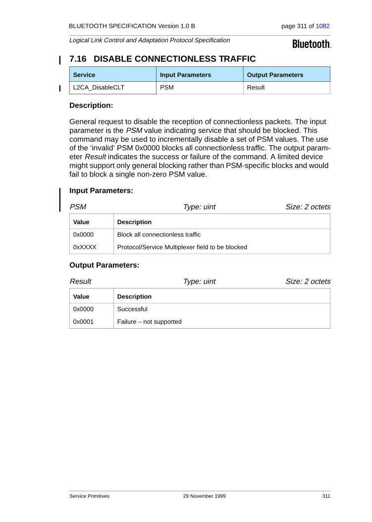
BLUETOOTH SPECIFICATION Version 1.0 B page 311 of 1082
Logical Link Control and Adaptation Protocol Specification
7.16 DISABLE CONNECTIONLESS TRAFFIC
Description:
General request to disable the reception of connectionless packets. The input parameter is the PSM value indicating service that should be blocked. This command may be used to incrementally disable a set of PSM values. The use of the ‘invalid’ PSM 0x0000 blocks all connectionless traffic. The output param-eter Result indicates the success or failure of the command. A limited device might support only general blocking rather than PSM-specific blocks and would fail to block a single non-zero PSM value.
Input Parameters:
PSM Type: uint Size: 2 octets
Output Parameters:
Result Type: uint Size: 2 octets
Service Input Parameters Output Parameters
L2CA_DisableCLT PSM Result
Value Description
0x0000 Block all connectionless traffic
0xXXXX Protocol/Service Multiplexer field to be blocked
Value Description
0x0000 Successful
0x0001 Failure – not supported
Service Primitives 29 November 1999 311

BLUETOOTH SPECIFICATION Version 1.0 B page 312 of 1082
Logical Link Control and Adaptation Protocol Specification
7.17 ENABLE CONNECTIONLESS TRAFFIC
Description:
General request to enable the reception of connectionless packets. The input parameter is the PSM value indicating the service that should be unblocked. This command may be used to incrementally enable a set of PSM values. The use of the ‘invalid’ PSM 0x0000 enables all connectionless traffic. The output parameter Result indicates the success or failure of the command. A limited device might support only general enabling rather than PSM-specific filters, and would fail to enable a single non-zero PSM value.
Input Parameters:
PSM Type: uint Size: 2 octets
Output Parameters:
Result Type: uint Size: 2 octets
Service Input Parameters Output Parameters
L2CA_EnableCLT PSM Result
Value Description
0x0000 Enable all connectionless traffic
0xXXXX Protocol/Service Multiplexer field to enable
Value Description
0x0000 Successful
0x0001 Failure – not supported
312 29 November 1999 Service Primitives
BLUETOOTH SPECIFICATION Version 1.0 B page 313 of 1082
Logical Link Control and Adaptation Protocol Specification
8 SUMMARY
The Logical Link Control and Adaptation Protocol (L2CAP) is one of two link level protocols running over the Baseband. L2CAP is responsible for higher level protocol multiplexing, MTU abstraction, group management, and convey-ing quality of service information to the link level.
Protocol multiplexing is supported by defining channels. Each channel is bound to a single protocol in a many-to-one fashion. Multiple channels can be bound to the same protocol, but a channel cannot be bound to multiple protocols. Each L2CAP packet received on a channel is directed to the appropriate higher level protocol.
L2CAP abstracts the variable-sized packets used by the Baseband Protocol (page 33). It supports large packet sizes up to 64 kilobytes using a low-overhead segmentation-and-reassembly mechanism.
Group management provides the abstraction of a group of units allowing more efficient mapping between groups and members of the Bluetooth piconet. Group communication is connectionless and unreliable. When composed of only a pair of units, groups provide connectionless channel alternative to L2CAP’s connection-oriented channel.
L2CAP conveys QoS information across channels and provides some admis-sion control to prevent additional channels from violating existing QoS con-tracts.
Summary 29 November 1999 313

BLUETOOTH SPECIFICATION Version 1.0 B page 314 of 1082
Logical Link Control and Adaptation Protocol Specification
9 REFERENCES
[1] Internet Engineering Task Force, “A Proposed Flow Specification”, RFC 1363, September 1992.
314 29 November 1999 References

BLUETOOTH SPECIFICATION Version 1.0 B page 315 of 1082
Logical Link Control and Adaptation Protocol Specification
10 LIST OF FIGURES
Figure 1.1: L2CAP within protocol layers ...................................................249Figure 1.2: ACL Payload Header for single-slot packets............................250Figure 1.3: ACL Payload Header for multi-slot packets .............................250Figure 1.4: L2CAP in Bluetooth Protocol Architecture ...............................251Figure 2.1: Channels between devices ......................................................254Figure 2.2: L2CAP Architecture..................................................................255Figure 2.3: L2CAP SAR Variables..............................................................255Figure 2.4: L2CAP segmentation ...............................................................256Figure 2.5: Segmentation and Reassembly Services in a unit
with an HCI ..............................................................................257Figure 3.1: L2CAP Layer Interactions ........................................................258Figure 3.2: MSC of Layer Interactions........................................................259Figure 3.3: State Machine Example ...........................................................270Figure 3.4: Message Sequence Chart of Basic Operation.........................271Figure 4.1: L2CAP Packet (field sizes in bits) ............................................272Figure 4.2: Connectionless Packet.............................................................273Figure 5.1: Signalling Command Packet Format........................................275Figure 5.2: Command format .....................................................................275Figure 5.3: Command Reject Packet .........................................................277Figure 5.4: Connection Request Packet.....................................................278Figure 5.5: Connection Response Packet..................................................279Figure 5.6: Configuration Request Packet .................................................281Figure 5.7: Configuration Request Flags field format.................................281Figure 5.8: Configuration Response Packet...............................................283Figure 5.9: Configuration Response Flags field format ..............................283Figure 5.10: Disconnection Request Packet ................................................285Figure 5.11: Disconnection Response Packet .............................................286Figure 5.12: Echo Request Packet ..............................................................286Figure 5.13: Echo Response Packet............................................................287Figure 5.14: Information Request Packet.....................................................287Figure 5.15: Information Response Packet ..................................................288Figure 6.1: Configuration option format......................................................289Figure 6.2: MTU Option Format .................................................................290Figure 6.3: Flush Timeout ..........................................................................290Figure 6.4: Quality of Service Flow Specification.......................................291Figure 6.5: Configuration State Machine....................................................294
Figure I Basic MTU exchange ..............................................................318Figure II Dealing with Unknown Options ...............................................319Figure III Unsuccessful Configuration Request ......................................320
List of Figures 29 November 1999 315
BLUETOOTH SPECIFICATION Version 1.0 B page 316 of 1082
Logical Link Control and Adaptation Protocol Specification
11 LIST OF TABLES
Table 1.1: Logical channel L_CH field contents .......................................250Table 2.1: CID Definitions.........................................................................253Table 2.2: Types of Channel Identifiers ....................................................254Table 3.1: L2CAP Channel State Machine ...............................................267Table 5.1: Signalling Command Codes ....................................................276Table 5.2: Reason Code Descriptions ......................................................277Table 5.3: Reason Data values ................................................................278Table 5.4: Defined PSM Values ................................................................278Table 5.5: Result values ...........................................................................280Table 5.6: Status values ...........................................................................280Table 5.7: Configuration Response Result codes ....................................284Table 5.8: InfoType definitions..................................................................287Table 5.9: Information Response Result values .......................................288Table 5.10: Information Response Data fields............................................288Table 6.1: Service type definitions............................................................292Table 6.2: Parameters allowed in Request...............................................293Table 6.3: Parameters allowed in Response ............................................294
Table I Result of Second Link Timeout Request .................................322Table II Result of Second Flush Timeout Request ..............................322
316 29 November 1999 List of Tables

BLUETOOTH SPECIFICATION Version 1.0 B page 317 of 1082
Logical Link Control and Adaptation Protocol Specification
TERMS AND ABBREVIATIONS
12 APPENDIX
Baseband Baseband Protocol
IETF Internet Engineering Task Force
IP Internet Protocol
IrDA Infra-red Data Association
L_CH Logical Channel
LC Link Controller
LM Link Manager
LMP Link Manager Protocol
MTU Maximum Transmission Unit
PPP Point-to-Point Protocol
Reliable Characteristic of an L2CAP channel that has an infinite flush timeout
RFC Request For Comments
SAR Segmentation and Reassembly
Appendix 29 November 1999 317
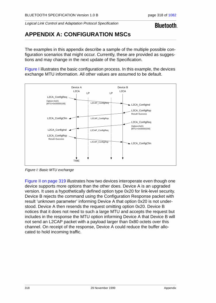
BLUETOOTH SPECIFICATION Version 1.0 B page 318 of 1082
Logical Link Control and Adaptation Protocol Specification
APPENDIX A: CONFIGURATION MSCs
The examples in this appendix describe a sample of the multiple possible con-figuration scenarios that might occur. Currently, these are provided as sugges-tions and may change in the next update of the Specification.
Figure I illustrates the basic configuration process. In this example, the devices exchange MTU information. All other values are assumed to be default.
Figure I: Basic MTU exchange
Figure II on page 319 illustrates how two devices interoperate even though one device supports more options than the other does. Device A is an upgraded version. It uses a hypothetically defined option type 0x20 for link-level security. Device B rejects the command using the Configuration Response packet with result ’unknown parameter’ informing Device A that option 0x20 is not under-stood. Device A then resends the request omitting option 0x20. Device B notices that it does not need to such a large MTU and accepts the request but includes in the response the MTU option informing Device A that Device B will not send an L2CAP packet with a payload larger than 0x80 octets over this channel. On receipt of the response, Device A could reduce the buffer allo-cated to hold incoming traffic.
L2CAP_ConfigReq
Device A Device B
L2CAP_ConfigRsp
L2CA_ConfigReq
L2CA_ConfigInd
L2CA_ConfigRsp
L2CA_ConfigCfm
TIME
LP LPL2CA L2CA
Option=0x01[MTU=0x00000100]
Result=Success
L2CA_ConfigReq
L2CA_ConfigInd
Option=0x01[MTU=0x00000200]
L2CA_ConfigRsp
L2CA_ConfigCfm
Result=SuccessL2CAP_ConfigRsp
L2CAP_ConfigReq
318 29 November 1999 Appendix

BLUETOOTH SPECIFICATION Version 1.0 B page 319 of 1082
Logical Link Control and Adaptation Protocol Specification
Figure II: Dealing with Unknown Options
Figure III on page 320 illustrates an unsuccessful configuration request. There are two problems described by this example. The first problem is that the con-figuration request is placed in an L2CAP packet that cannot be accepted by the remote device, due to its size. The remote device informs the sender of this problem using the Command Reject message. Device A then resends the con-figuration options using two smaller L2CAP_ConfigReq messages.
The second problem is an attempt to configure a channel with an invalid CID. For example device B may not have an open connection on that CID (0x01234567 in this example case).
Device A Device B
TIME
LP LPL2CA L2CA
L2CAP_ConfigReq
L2CAP_ConfigRsp
L2CA_ConfigReq
L2CA_ConfigInd
L2CA_ConfigRsp
L2CA_ConfigCfm
Option=0x01[MTU=0x00000100]Option=0x20[Data=0xFA12D823]
Result=Unknown optionOption=0x20
L2CAP_ConfigReq
L2CAP_ConfigRsp
L2CA_ConfigReq
L2CA_ConfigInd
L2CA_ConfigRsp
L2CA_ConfigCfm
Option=0x01[MTU=0x00000100]
Result=Success[MTU=0x00000080]
L2CA_ConfigReq
L2CA_ConfigInd
Option=0x01[MTU=0x00000200]
L2CA_ConfigRsp
L2CA_ConfigCfm
Result=Success
L2CAP_ConfigReq
L2CAP_ConfigRsp
Appendix 29 November 1999 319

BLUETOOTH SPECIFICATION Version 1.0 B page 320 of 1082
Logical Link Control and Adaptation Protocol Specification
Figure III: Unsuccessful Configuration Request
Device A Device B
TIME
LP LPL2CA L2CA
L2CAP_ConfigReq
L2CAP_CmdReject
L2CA_ConfigReq
ID=0x1234DCID=0x01234567Option=0x01[MTU=0x00000100]Option=0x20[Data=BIG]
ID=0x1234Reason=0x0001(MTU exceeded)Data=0x80
L2CAP_CmdReject
L2CAP_ConfigReqID=0x1235DCID=0x01234567Option=0x01[MTU=0x00000100]C flag set to 1
ID=0x1235Reason=0x0002(Invalid CID)
L2CAP_CmdReject
ID=0x1236Reason=0x0002(Invalid CID)
L2CAP_ConfigReq
ID=0x1236DCID=0x01234567Option=0x20[Data=BIG]
L2CA_ConfigCfmNeg
320 29 November 1999 Appendix

BLUETOOTH SPECIFICATION Version 1.0 B page 321 of 1082
Logical Link Control and Adaptation Protocol Specification
APPENDIX B: IMPLEMENTATION GUIDELINES
This section contains some guidelines for implementations. These guidelines are not part of the compliance tests. At the moment they are simply sugges-tions on how to solve some difficult problems.
RTX TIMER
Implementations should not start this timer on an L2CAP Connection Request packet unless the physical link has been established. Otherwise the Baseband paging mechanism might increase the cost of the request beyond that of the minimal timeout value. If an implementation performs some form of security check it is recommended that the connection pending response be sent back prior to any consultation with a security manager that might perform Baseband authentication commands. If any security check requires user interaction, the link might timeout waiting for the user to enter a PIN.
QOS MAPPING TO LM AND L2CAP IMPLEMENTATIONS
Token Rate
The Link Manager (LM) should ensure data is removed from the transmission buffer at this rate. The LM should ensure the polling interval is fast enough to support this data rate. The polling interval should be adjusted if the packet type changes. If the buffer overflows, and the service type is Guaranteed, a QoS violation should be reported. If the service type is Best Effort, and a Token Rate was non-zero, a QoS violation should also be reported.
Given a Token Rate of 0xFFFFFFFF, and Service Type of Guaranteed, the LM should refuse any additional connections from remote devices and disable all periodic scans.
Token Bucket Size
L2CAP implementations should ensure that a buffer meeting the size request is allocated for the channel. If no buffer is available, and the service type is Guaranteed, the request should be rejected. If no appropriately sized buffer is available, and the service type is Best Effort, the largest available buffer should be allocated.
Peak Bandwidth
If the token bucket buffer overflows, a QoS violation should be raised.
Appendix 29 November 1999 321

BLUETOOTH SPECIFICATION Version 1.0 B page 322 of 1082
Logical Link Control and Adaptation Protocol Specification
Latency
The LM should ensure the polling interval is at least this value. If the polling interval necessary to support the token rate is less than this value, the smaller interval should be used. If this interval cannot be supported, a QoS violation should be raised.
Delay Variation
The LM may ignore this value because there is no clear mapping between L2CAP packet delays and the necessary polling interval without requiring the LM to comprehend the length field in L2CAP packets.
COLLISION TABLES
Current Value Requested Value Result
X X X
X Y If (X < Y) then X, else Y
Table I: Result of Second Link Timeout Request
Current Value Requested Value Result
N 0 N
N N N
N M != N Reject
Table II: Result of Second Flush Timeout Request
322 29 November 1999 Appendix
Part E
SERVICE DISCOVERY PROTOCOL (SDP)
This specification defines a protocol for locating ser-vices provided by or available through a Bluetooth device.

324 29 November 1999
BLUETOOTH SPECIFICATION Version 1.0 B page 324 of 1082
Service Discovery Protocol

BLUETOOTH SPECIFICATION Version 1.0 B page 325 of 1082
Service Discovery Protocol
CONTENTS
1 Introduction ......................................................................................3271.1 General Description .................................................................3271.2 Motivation.................................................................................3271.3 Requirements...........................................................................3271.4 Non-requirements and Deferred Requirements.......................3281.5 Conventions .............................................................................329
1.5.1 Bit And Byte Ordering Conventions.............................329
2 Overview ...........................................................................................3302.1 SDP Client-Server Interaction..................................................3302.2 Service Record.........................................................................3322.3 Service Attribute.......................................................................3342.4 Attribute ID ...............................................................................3352.5 Attribute Value..........................................................................3352.6 Service Class ...........................................................................336
2.6.1 A Printer Service Class Example ................................3362.7 Searching for Services.............................................................337
2.7.1 UUID............................................................................3372.7.2 Service Search Patterns..............................................338
2.8 Browsing for Services ..............................................................3382.8.1 Example Service Browsing Hierarchy .........................339
3 Data Representation ........................................................................3413.1 Data Element ...........................................................................3413.2 Data Element Type Descriptor .................................................3413.3 Data Element Size Descriptor ..................................................3423.4 Data Element Examples...........................................................343
4 Protocol Description........................................................................3444.1 Transfer Byte Order .................................................................3444.2 Protocol Data Unit Format........................................................3444.3 Partial Responses and Continuation State ..............................3464.4 Error Handling..........................................................................346
4.4.1 SDP_ErrorResponse PDU ..........................................3474.5 ServiceSearch Transaction ......................................................348
4.5.1 SDP_ServiceSearchRequest PDU..............................3484.5.2 SDP_ServiceSearchResponse PDU...........................349
4.6 ServiceAttribute Transaction ....................................................3514.6.1 SDP_ServiceAttributeRequest PDU............................3514.6.2 SDP_ServiceAttributeResponse PDU.........................352
29 November 1999 325

BLUETOOTH SPECIFICATION Version 1.0 B page 326 of 1082
Service Discovery Protocol
4.7 ServiceSearchAttribute Transaction ........................................3544.7.1 SDP_ServiceSearchAttributeRequest PDU................3544.7.2 SDP_ServiceSearchAttributeResponse PDU .............356
5 Service Attribute Definitions...........................................................3585.1 Universal Attribute Definitions..................................................358
5.1.1 ServiceRecordHandle Attribute...................................3585.1.2 ServiceClassIDList Attribute........................................3595.1.3 ServiceRecordState Attribute......................................3595.1.4 ServiceID Attribute ......................................................3595.1.5 ProtocolDescriptorList Attribute...................................3605.1.6 BrowseGroupList Attribute ..........................................3615.1.7 LanguageBaseAttributeIDList Attribute.......................3615.1.8 ServiceInfoTimeToLive Attribute .................................3625.1.9 ServiceAvailability Attribute.........................................3635.1.10 BluetoothProfileDescriptorList Attribute ......................3635.1.11 DocumentationURL Attribute ......................................3645.1.12 ClientExecutableURL Attribute....................................3645.1.13 IconURL Attribute........................................................3655.1.14 ServiceName Attribute ................................................3655.1.15 ServiceDescription Attribute........................................3665.1.16 ProviderName Attribute...............................................3665.1.17 Reserved Universal Attribute IDs................................366
5.2 ServiceDiscoveryServer Service Class Attribute Definitions ...3675.2.1 ServiceRecordHandle Attribute...................................3675.2.2 ServiceClassIDList Attribute........................................3675.2.3 VersionNumberList Attribute .......................................3675.2.4 ServiceDatabaseState Attribute..................................3685.2.5 Reserved Attribute IDs................................................368
5.3 BrowseGroupDescriptor Service Class Attribute Definitions ...3695.3.1 ServiceClassIDList Attribute........................................3695.3.2 GroupID Attribute ........................................................3695.3.3 Reserved Attribute IDs................................................369
Appendix A – Background Information ...................................................370
Appendix B – Example SDP Transactions ...............................................371
326 29 November 1999

BLUETOOTH SPECIFICATION Version 1.0 B page 327 of 1082
Service Discovery Protocol
1 INTRODUCTION
1.1 GENERAL DESCRIPTION
The service discovery protocol (SDP) provides a means for applications to dis-cover which services are available and to determine the characteristics of those available services.
1.2 MOTIVATION
Service Discovery in the Bluetooth environment, where the set of services that are available changes dynamically based on the RF proximity of devices in motion, is qualitatively different from service discovery in traditional network-based environments. The service discovery protocol defined in this specifica-tion is intended to address the unique characteristics of the Bluetooth environ-ment. See “Appendix A – Background Information,” on page 370, for further information on this topic.
1.3 REQUIREMENTS
The following capabilities have been identified as requirements for version 1.0 of the Service Discovery Protocol.
1. SDP shall provide the ability for clients to search for needed services based on specific attributes of those services.
2. SDP shall permit services to be discovered based on the class of service.
3. SDP shall enable browsing of services without a priori knowledge of the spe-cific characteristics of those services.
4. SDP shall provide the means for the discovery of new services that become available when devices enter RF proximity with a client device as well as when a new service is made available on a device that is in RF proximity with the client device.
5. SDP shall provide a mechanism for determining when a service becomes unavailable when devices leave RF proximity with a client device as well as when a service is made unavailable on a device that is in RF proximity with the client device.
6. SDP shall provide for services, classes of services, and attributes of ser-vices to be uniquely identified.
7. SDP shall allow a client on one device to discover a service on another device without consulting a third device.
8. SDP should be suitable for use on devices of limited complexity.
9. SDP shall provide a mechanism to incrementally discover information about the services provided by a device. This is intended to minimize the quantity
Introduction 29 November 1999 327

BLUETOOTH SPECIFICATION Version 1.0 B page 328 of 1082
Service Discovery Protocol
of data that must be exchanged in order to determine that a particular ser-vice is not needed by a client.
10.SDP should support the caching of service discovery information by inter-mediary agents to improve the speed or efficiency of the discovery process.
11.SDP should be transport independent.
12.SDP shall function while using L2CAP as its transport protocol.
13.SDP shall permit the discovery and use of services that provide access to other service discovery protocols.
14.SDP shall support the creation and definition of new services without requir-ing registration with a central authority.
1.4 NON-REQUIREMENTS AND DEFERRED REQUIREMENTS
The Bluetooth SIG recognizes that the following capabilities are related to ser-vice discovery. These items are not addressed in SDP version 1.0. However, some may be addressed in future revisions of the specification.
1. SDP 1.0 does not provide access to services. It only provides access to information about services.
2. SDP 1.0 does not provide brokering of services.
3. SDP 1.0 does not provide for negotiation of service parameters.
4. SDP 1.0 does not provide for billing of service use.
5. SDP 1.0 does not provide the means for a client to control or change the operation of a service.
6. SDP 1.0 does not provide an event notification when services, or information about services, become unavailable.
7. SDP 1.0 does not provide an event notification when attributes of services are modified.
8. This specification does not define an application programming interface for SDP.
9. SDP 1.0 does not provide support for service agent functions such as ser-vice aggregation or service registration.
328 29 November 1999 Introduction

BLUETOOTH SPECIFICATION Version 1.0 B page 329 of 1082
Service Discovery Protocol
1.5 CONVENTIONS
1.5.1 Bit And Byte Ordering Conventions
When multiple bit fields are contained in a single byte and represented in a drawing in this specification, the more significant (high-order) bits are shown toward the left and less significant (low-order) bits toward the right.
Multiple-byte fields are drawn with the more significant bytes toward the left and the less significant bytes toward the right. Multiple-byte fields are trans-ferred in network byte order. See Section 4.1 Transfer Byte Order on page 344.
Introduction 29 November 1999 329

BLUETOOTH SPECIFICATION Version 1.0 B page 330 of 1082
Service Discovery Protocol
2 OVERVIEW
2.1 SDP CLIENT-SERVER INTERACTION
Figure 2.1:
The service discovery mechanism provides the means for client applications to discover the existence of services provided by server applications as well as the attributes of those services. The attributes of a service include the type or class of service offered and the mechanism or protocol information needed to utilize the service.
As far as the Service Discovery Protocol (SDP) is concerned, the configuration shown in Figure 1 may be simplified to that shown in Figure 2.
Figure 2.2:
SDPClient
SDPServer
SDP requests
SDP responses
ServerApplication
ClientApplication
SDPClient
SDPServer
SDP requests
SDP responses
330 29 November 1999 Overview

BLUETOOTH SPECIFICATION Version 1.0 B page 331 of 1082
Service Discovery Protocol
SDP involves communication between an SDP server and an SDP client. The server maintains a list of service records that describe the characteristics of services associated with the server. Each service record contains information about a single service. A client may retrieve information from a service record maintained by the SDP server by issuing an SDP request.
If the client, or an application associated with the client, decides to use a ser-vice, it must open a separate connection to the service provider in order to uti-lize the service. SDP provides a mechanism for discovering services and their attributes (including associated service access protocols), but it does not pro-vide a mechanism for utilizing those services (such as delivering the service access protocols).
There is a maximum of one SDP server per Bluetooth device. (If a Bluetooth device acts only as a client, it needs no SDP server.) A single Bluetooth device may function both as an SDP server and as an SDP client. If multiple applica-tions on a device provide services, an SDP server may act on behalf of those service providers to handle requests for information about the services that they provide.
Similarly, multiple client applications may utilize an SDP client to query servers on behalf of the client applications.
The set of SDP servers that are available to an SDP client can change dynam-ically based on the RF proximity of the servers to the client. When a server becomes available, a potential client must be notified by a means other than SDP so that the client can use SDP to query the server about its services. Sim-ilarly, when a server leaves proximity or becomes unavailable for any reason, there is no explicit notification via the service discovery protocol. However, the client may use SDP to poll the server and may infer that the server is not avail-able if it no longer responds to requests.
Additional information regarding application interaction with SDP is contained in the Bluetooth Service Discovery Profile document.
Overview 29 November 1999 331
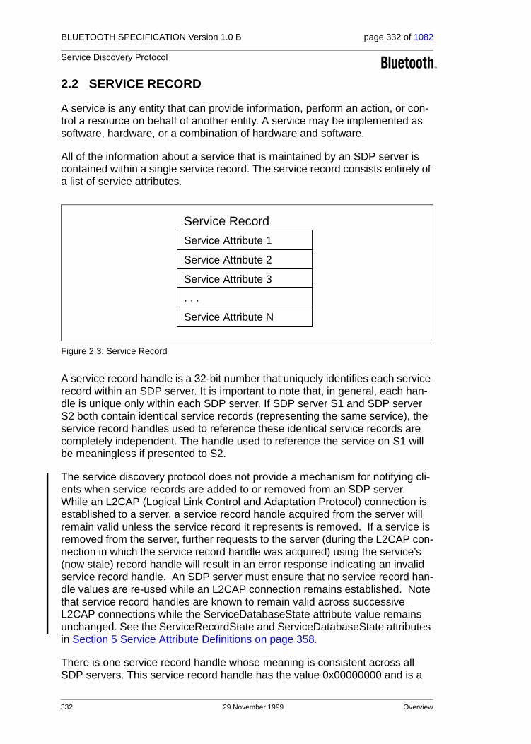
BLUETOOTH SPECIFICATION Version 1.0 B page 332 of 1082
Service Discovery Protocol
2.2 SERVICE RECORD
A service is any entity that can provide information, perform an action, or con-trol a resource on behalf of another entity. A service may be implemented as software, hardware, or a combination of hardware and software.
All of the information about a service that is maintained by an SDP server is contained within a single service record. The service record consists entirely of a list of service attributes.
Figure 2.3: Service Record
A service record handle is a 32-bit number that uniquely identifies each service record within an SDP server. It is important to note that, in general, each han-dle is unique only within each SDP server. If SDP server S1 and SDP server S2 both contain identical service records (representing the same service), the service record handles used to reference these identical service records are completely independent. The handle used to reference the service on S1 will be meaningless if presented to S2.
The service discovery protocol does not provide a mechanism for notifying cli-ents when service records are added to or removed from an SDP server. While an L2CAP (Logical Link Control and Adaptation Protocol) connection is established to a server, a service record handle acquired from the server will remain valid unless the service record it represents is removed. If a service is removed from the server, further requests to the server (during the L2CAP con-nection in which the service record handle was acquired) using the service’s (now stale) record handle will result in an error response indicating an invalid service record handle. An SDP server must ensure that no service record han-dle values are re-used while an L2CAP connection remains established. Note that service record handles are known to remain valid across successive L2CAP connections while the ServiceDatabaseState attribute value remains unchanged. See the ServiceRecordState and ServiceDatabaseState attributes in Section 5 Service Attribute Definitions on page 358.
There is one service record handle whose meaning is consistent across all SDP servers. This service record handle has the value 0x00000000 and is a
Service Attribute 1
Service Attribute 2
Service Attribute 3
Service Attribute N
Service Record
. . .
332 29 November 1999 Overview
BLUETOOTH SPECIFICATION Version 1.0 B page 333 of 1082
Service Discovery Protocol
handle to the service record that represents the SDP server itself. This service record contains attributes for the SDP server and the protocol it supports. For example, one of its attributes is the list of SDP protocol versions supported by the server. Service record handle values 0x00000001-0x0000FFFF are reserved.
Overview 29 November 1999 333
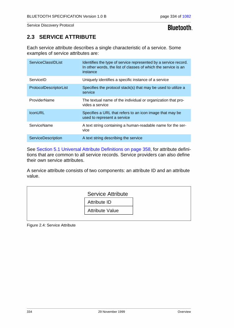
BLUETOOTH SPECIFICATION Version 1.0 B page 334 of 1082
Service Discovery Protocol
2.3 SERVICE ATTRIBUTE
Each service attribute describes a single characteristic of a service. Some examples of service attributes are:
See Section 5.1 Universal Attribute Definitions on page 358, for attribute defini-tions that are common to all service records. Service providers can also define their own service attributes.
A service attribute consists of two components: an attribute ID and an attribute value.
Figure 2.4: Service Attribute
ServiceClassIDList Identifies the type of service represented by a service record. In other words, the list of classes of which the service is an instance
ServiceID Uniquely identifies a specific instance of a service
ProtocolDescriptorList Specifies the protocol stack(s) that may be used to utilize a service
ProviderName The textual name of the individual or organization that pro-vides a service
IconURL Specifies a URL that refers to an icon image that may be used to represent a service
ServiceName A text string containing a human-readable name for the ser-vice
ServiceDescription A text string describing the service
Attribute ID
Attribute Value
Service Attribute
334 29 November 1999 Overview
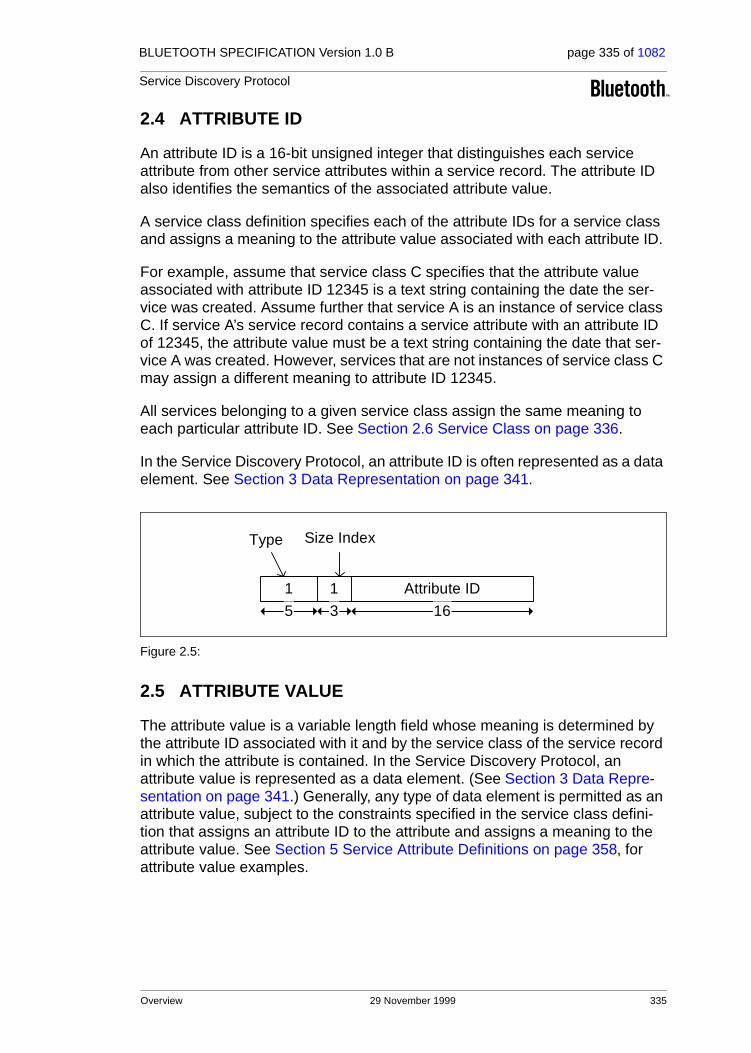
BLUETOOTH SPECIFICATION Version 1.0 B page 335 of 1082
Service Discovery Protocol
2.4 ATTRIBUTE ID
An attribute ID is a 16-bit unsigned integer that distinguishes each service attribute from other service attributes within a service record. The attribute ID also identifies the semantics of the associated attribute value.
A service class definition specifies each of the attribute IDs for a service class and assigns a meaning to the attribute value associated with each attribute ID.
For example, assume that service class C specifies that the attribute value associated with attribute ID 12345 is a text string containing the date the ser-vice was created. Assume further that service A is an instance of service class C. If service A’s service record contains a service attribute with an attribute ID of 12345, the attribute value must be a text string containing the date that ser-vice A was created. However, services that are not instances of service class C may assign a different meaning to attribute ID 12345.
All services belonging to a given service class assign the same meaning to each particular attribute ID. See Section 2.6 Service Class on page 336.
In the Service Discovery Protocol, an attribute ID is often represented as a data element. See Section 3 Data Representation on page 341.
Figure 2.5:
2.5 ATTRIBUTE VALUE
The attribute value is a variable length field whose meaning is determined by the attribute ID associated with it and by the service class of the service record in which the attribute is contained. In the Service Discovery Protocol, an attribute value is represented as a data element. (See Section 3 Data Repre-sentation on page 341.) Generally, any type of data element is permitted as an attribute value, subject to the constraints specified in the service class defini-tion that assigns an attribute ID to the attribute and assigns a meaning to the attribute value. See Section 5 Service Attribute Definitions on page 358, for attribute value examples.
1 1
Type
Attribute ID
Size Index
5 3 16
Overview 29 November 1999 335

BLUETOOTH SPECIFICATION Version 1.0 B page 336 of 1082
Service Discovery Protocol
2.6 SERVICE CLASS
Each service is an instance of a service class. The service class definition pro-vides the definitions of all attributes contained in service records that represent instances of that class. Each attribute definition specifies the numeric value of the attribute ID, the intended use of the attribute value, and the format of the attribute value. A service record contains attributes that are specific to a ser-vice class as well as universal attributes that are common to all services.
Each service class is also assigned a unique identifier. This service class iden-tifier is contained in the attribute value for the ServiceClassIDList attribute, and is represented as a UUID (see Section 2.7.1 UUID on page 337). Since the for-mat and meanings of many attributes in a service record are dependent on the service class of the service record, the ServiceClassIDList attribute is very important. Its value should be examined or verified before any class-specific attributes are used. Since all of the attributes in a service record must conform to all of the service’s classes, the service class identifiers contained in the Ser-viceClassIDList attribute are related. Typically, each service class is a subclass of another class whose identifier is contained in the list. A service subclass def-inition differs from its superclass in that the subclass contains additional attribute definitions that are specific to the subclass. The service class identifi-ers in the ServiceClassIDList attribute are listed in order from the most specific class to the most general class.
When a new service class is defined that is a subclass of an existing service class, the new service class retains all of the attributes defined in its super-class. Additional attributes will be defined that are specific to the new service class. In other words, the mechanism for adding new attributes to some of the instances of an existing service class is to create a new service class that is a subclass of the existing service class.
2.6.1 A Printer Service Class Example
A color postscript printer with duplex capability might conform to 4 Service-Class definitions and have a ServiceClassIDList with UUIDs (See Section 2.7.1 UUID on page 337.) representing the following ServiceClasses:
DuplexColorPostscriptPrinterServiceClassID,ColorPostscriptPrinterServiceClassID,PostscriptPrinterServiceClassID,PrinterServiceClassID
Note that this example is only illustrative. This may not be a practical printer class hierarchy.
336 29 November 1999 Overview
BLUETOOTH SPECIFICATION Version 1.0 B page 337 of 1082
Service Discovery Protocol
2.7 SEARCHING FOR SERVICES
Once an SDP client has a service record handle, it may easily request the val-ues of specific attributes, but how does a client initially acquire a service record handle for the desired service records? The Service Search transaction allows a client to retrieve the service record handles for particular service records based on the values of attributes contained within those service records.
The capability search for service records based on the values of arbitrary attributes is not provided. Rather, the capability is provided to search only for attributes whose values are Universally Unique Identifiers1 (UUIDs). Important attributes of services that can be used to search for a service are represented as UUIDs.
2.7.1 UUID
A UUID is a universally unique identifier that is guaranteed to be unique across all space and all time. UUIDs can be independently created in a distributed fashion. No central registry of assigned UUIDs is required. A UUID is a 128-bit value.
To reduce the burden of storing and transferring 128-bit UUID values, a range of UUID values has been pre-allocated for assignment to often-used, regis-tered purposes. The first UUID in this pre-allocated range is known as the Bluetooth Base UUID and has the value 00000000-0000-1000-7007-00805F9B34FB, from the Bluetooth Assigned Numbers document. UUID val-ues in the pre-allocated range have aliases that are represented as 16-bit or 32-bit values. These aliases are often called 16-bit and 32-bit UUIDs, but it is important to note that each actually represents a 128-bit UUID value.
The full 128-bit value of a 16-bit or 32-bit UUID may be computed by a simple arithmetic operation.
128_bit_value = 16_bit_value * 296 + Bluetooth_Base_UUID
128_bit_value = 32_bit_value * 296 + Bluetooth_Base_UUID
A 16-bit UUID may be converted to 32-bit UUID format by zero-extending the 16-bit value to 32-bits. An equivalent method is to add the 16-bit UUID value to a zero-valued 32-bit UUID.
Note that two 16-bit UUIDs may be compared directly, as may two 32-bit UUIDs or two 128-bit UUIDs. If two UUIDs of differing sizes are to be com-pared, the shorter UUID must be converted to the longer UUID format before comparison.
1. The format of UUIDs is defined by the International Organization for Standardization in ISO/IEC 11578:1996. “Information technology – Open Systems Interconnection – Remote Proce-dure Call (RPC)”
Overview 29 November 1999 337

BLUETOOTH SPECIFICATION Version 1.0 B page 338 of 1082
Service Discovery Protocol
2.7.2 Service Search Patterns
A service search pattern is a list of UUIDs used to locate matching service records. A service search pattern is said to match a service record if each and every UUID in the service search pattern is contained within any of the service record’s attribute values. The UUIDs need not be contained within any specific attributes or in any particular order within the service record. The service search pattern matches if the UUIDs it contains constitute a subset of the UUIDs in the service record’s attribute values. The only time a service search pattern does not match a service record is if the service search pattern con-tains at least one UUID that is not contained within the service record’s attribute values. Note also that a valid service search pattern must contain at least one UUID.
2.8 BROWSING FOR SERVICES
Normally, a client searches for services based on some desired characteris-tic(s) (represented by a UUID) of the services. However, there are times when it is desirable to discover which types of services are described by an SDP server’s service records without any a priori information about the services. This process of looking for any offered services is termed browsing. In SDP, the mechanism for browsing for services is based on an attribute shared by all ser-vice classes. This attribute is called the BrowseGroupList attribute. The value of this attribute contains a list of UUIDs. Each UUID represents a browse group with which a service may be associated for the purpose of browsing.
When a client desires to browse an SDP server’s services, it creates a service search pattern containing the UUID that represents the root browse group. All services that may be browsed at the top level are made members of the root browse group by having the root browse group’s UUID as a value within the BrowseGroupList attribute.
Normally, if an SDP server has relatively few services, all of its services will be placed in the root browse group. However, the services offered by an SDP server may be organized in a browse group hierarchy, by defining additional browse groups below the root browse group. Each of these additional browse groups is described by a service record with a service class of BrowseGroupDescriptor.
A browse group descriptor service record defines a new browse group by means of its Group ID attribute. In order for a service contained in one of these newly defined browse groups to be browseable, the browse group descriptor service record that defines the new browse group must in turn be browseable. The hierarchy of browseable services that is provided by the use of browse group descriptor service records allows the services contained in an SDP server to be incrementally browsed and is particularly useful when the SDP server contains many service records.
338 29 November 1999 Overview

BLUETOOTH SPECIFICATION Version 1.0 B page 339 of 1082
Service Discovery Protocol
2.8.1 Example Service Browsing Hierarchy
Here is a fictitious service browsing hierarchy that may illuminate the manner in which browse group descriptors are used. Browse group descriptor service records are identified with (G); other service records with (S).
Figure 2.6:
This table shows the services records and service attributes necessary to implement the browse hierarchy.
Service Name Service Class Attribute Name Attribute Value
Entertainment BrowseGroupDescriptor BrowseGroupList PublicBrowseRoot
GroupID EntertainmentID
News BrowsegroupDescriptor BrowseGroupList PublicBrowseRoot
GroupID NewsID
Reference BrowseGroupDescriptor BrowseGroupList PublicBrowseRoot
GroupID ReferenceID
Games BrowseGroupDescriptor BrowseGroupList EntertainmentID
GroupID GamesID
Movies BrowseGroupDescriptor BrowseGroupList EntertainmentID
GroupID MoviesID
Starcraft Video Game Class ID BrowseGroupList GamesID
Table 2.1:
Overview 29 November 1999 339

BLUETOOTH SPECIFICATION Version 1.0 B page 340 of 1082
Service Discovery Protocol
A Bug’s Life Movie Class ID BrowseGroupList MovieID
Dictionary Z Dictionary Class ID BrowseGroupList ReferenceID
Encyclopedia X Encyclopedia Class ID BrowseGroupList ReferenceID
New York Times Newspaper ID BrowseGroupList NewspaperID
London Times Newspaper ID BrowseGroupList NewspaperID
Local Newspaper Newspaper ID BrowseGroupList NewspaperID
Table 2.1:
340 29 November 1999 Overview

BLUETOOTH SPECIFICATION Version 1.0 B page 341 of 1082
Service Discovery Protocol
3 DATA REPRESENTATION
Attribute values can contain information of various types with arbitrary com-plexity; thus enabling an attribute list to be generally useful across a wide vari-ety of service classes and environments.
SDP defines a simple mechanism to describe the data contained within an attribute value. The primitive construct used is the data element.
3.1 DATA ELEMENT
A data element is a typed data representation. It consists of two fields: a header field and a data field. The header field, in turn, is composed of two parts: a type descriptor and a size descriptor. The data is a sequence of bytes whose length is specified in the size descriptor (described in Section 3.3 Data Element Size Descriptor on page 342) and whose meaning is (partially) speci-fied by the type descriptor.
3.2 DATA ELEMENT TYPE DESCRIPTOR
A data element type is represented as a 5-bit type descriptor. The type descrip-tor is contained in the most significant (high-order) 5 bits of the first byte of the data element header. The following types have been defined.
Type Descriptor Value
Valid Size Descriptor Values
Type Description
0 0 Nil, the null type
1 0, 1, 2, 3, 4 Unsigned Integer
2 0, 1, 2, 3, 4 Signed twos-complement integer
3 1, 2, 4 UUID, a universally unique identifier
4 5, 6, 7 Text string
5 0 Boolean
6 5, 6, 7 Data element sequence, a data element whose data field is a sequence of data elements
7 5, 6, 7 Data element alternative, data element whose data field is a sequence of data elements from which one data ele-ment is to be selected.
8 5, 6, 7 URL, a uniform resource locator
9-31 Reserved
Table 3.1:
Data Representation 29 November 1999 341

BLUETOOTH SPECIFICATION Version 1.0 B page 342 of 1082
Service Discovery Protocol
3.3 DATA ELEMENT SIZE DESCRIPTOR
The data element size descriptor is represented as a 3-bit size index followed by 0, 8, 16, or 32 bits. The size index is contained in the least significant (low-order) 3 bits of the first byte of the data element header. The size index is encoded as follows.
Size Index
Additional bits
Data Size
0 0 1 byte. Exception: if the data element type is nil, the data size is 0 bytes.
1 0 2 bytes
2 0 4 bytes
3 0 8 bytes
4 0 16 bytes
5 8 The data size is contained in the additional 8 bits, which are inter-preted as an unsigned integer.
6 16 The data size is contained in the additional 16 bits, which are interpreted as an unsigned integer.
7 32 The data size is contained in the additional 32 bits, which are interpreted as an unsigned integer.
Table 3.2:
342 29 November 1999 Data Representation

BLUETOOTH SPECIFICATION Version 1.0 B page 343 of 1082
Service Discovery Protocol
3.4 DATA ELEMENT EXAMPLES
Figure 3.1:
0 0
Type
Nil is represented as:
2 1
Type
A 16-bit signed integer is represented as:
16-bit data value
he 3 character ASCII string "Hat" is represented as:
4 5
Type Size Index
Size Index
Size Index
3
Size
’H’ ’a’ ’t’
5 3 16
5 3
5 3 8 24
Data Representation 29 November 1999 343

BLUETOOTH SPECIFICATION Version 1.0 B page 344 of 1082
Service Discovery Protocol
4 PROTOCOL DESCRIPTION
SDP is a simple protocol with minimal requirements on the underlying trans-port. It can function over a reliable packet transport (or even unreliable, if the client implements timeouts and repeats requests as necessary).
SDP uses a request/response model where each transaction consists of one request protocol data unit (PDU) and one response PDU. However, the requests may potentially be pipelined and responses may potentially be returned out of order.
In the specific case where SDP utilises the Bluetooth L2CAP transport proto-col, multiple SDP PDUs may be sent in a single L2CAP packet, but only one L2CAP packet per connection to a given SDP server may be outstanding at a given instant. Limiting SDP to sending one unacknowledged packet provides a simple form of flow control.
The protocol examples found in Appendix B – Example SDP Transactions, may be helpful in understanding the protocol transactions.
4.1 TRANSFER BYTE ORDER
The service discovery protocol transfers multiple-byte fields in standard net-work byte order (Big Endian), with more significant (high-order) bytes being transferred before less-significant (low-order) bytes.
4.2 PROTOCOL DATA UNIT FORMAT
Every SDP PDU consists of a PDU header followed by PDU-specific parame-ters. The header contains three fields: a PDU ID, a Transaction ID, and a ParameterLength. Each of these header fields is described here. Parameters may include a continuation state parameter, described below; PDU-specific parameters for each PDU type are described later in separate PDU descrip-tions.
Figure 4.1:
PDU Format:
Header:
Parameters:
PDU ID Transaction ID ParameterLength
1 byte 2 bytes 2 bytes
Parameter 1 Parameter 2 Parameter N
ParameterLength bytes
344 29 November 1999 Protocol Description

BLUETOOTH SPECIFICATION Version 1.0 B page 345 of 1082
Service Discovery Protocol
PDU ID: Size: 1 Byte
TransactionID: Size: 2 Bytes
ParameterLength: Size: 2 Bytes
Value Parameter Description
N The PDU ID field identifies the type of PDU. I.e. its meaning and the specific parameters.
0x00 Reserved
0x01 SDP_ErrorResponse
0x02 SDP_ServiceSearchRequest
0x03 SDP_ServiceSearchResponse
0x04 SDP_ServiceAttributeRequest
0x05 SDP_ServiceAttributeResponse
0x06 SDP_ServiceSearchAttributeRequest
0x07 SDP_ServiceSearchAttributeResponse
0x07-0xFF Reserved
Value Parameter Description
N The TransactionID field uniquely identifies request PDUs and is used to match response PDUs to request PDUs. The SDP client can choose any value for a request’s TransactionID provided that it is different from all outstanding requests. The TransactionID value in response PDUs is required to be the same as the request that is being responded to.Range: 0x0000 – 0xFFFF
Value Parameter Description
N The ParameterLength field specifies the length (in bytes) of all parame-ters contained in the PDU.Range: 0x0000 – 0xFFFF
Protocol Description 29 November 1999 345

BLUETOOTH SPECIFICATION Version 1.0 B page 346 of 1082
Service Discovery Protocol
4.3 PARTIAL RESPONSES AND CONTINUATION STATE
Some SDP requests may require responses that are larger than can fit in a sin-gle response PDU. In this case, the SDP server will generate a partial response along with a continuation state parameter. The continuation state parameter can be supplied by the client in a subsequent request to retrieve the next portion of the complete response. The continuation state parameter is a variable length field whose first byte contains the number of additional bytes of continuation information in the field. The format of the continuation information is not standardized among SDP servers. Each continuation state parameter is meaningful only to the SDP server that generated it.
Figure 4.2: Continuation State Format
After a client receives a partial response and the accompanying continuation state parameter, it can re-issue the original request (with a new transaction ID) and include the continuation state in the new request indicating to the server that the remainder of the original response is desired. The maximum allowable value of the InfoLength field is 16 (0x10).
Note that an SDP server can split a response at any arbitrary boundary when it generates a partial response. The SDP server may select the boundary based on the contents of the reply, but is not required to do so.
4.4 ERROR HANDLING
Each transaction consists of a request and a response PDU. Generally, each type of request PDU has a corresponding type of response PDU. However, if the server determines that a request is improperly formatted or for any reason the server cannot respond with the appropriate PDU type, it will respond with an SDP_ErrorResponse PDU.
Figure 4.3:
InfoLength Continuation Information
InfoLength bytes1 byte
Any Request
SDP_ErrorResponseClient Server
346 29 November 1999 Protocol Description

BLUETOOTH SPECIFICATION Version 1.0 B page 347 of 1082
Service Discovery Protocol
4.4.1 SDP_ErrorResponse PDU
Description:
The SDP server generates this PDU type in response to an improperly format-ted request PDU or when the SDP server, for whatever reason, cannot gener-ate an appropriate response PDU.
PDU Parameters:
ErrorCode: Size: 2 Bytes
ErrorInfo: Size: N Bytes
PDU Type PDU ID Parameters
SDP_ErrorResponse 0x01 ErrorCode,ErrorInfo
Value Parameter Description
N The ErrorCode identifies the reason that an SDP_ErrorResponse PDU was generated.
0x0000 Reserved
0x0001 Invalid/unsupported SDP version
0x0002 Invalid Service Record Handle
0x0003 Invalid request syntax
0x0004 Invalid PDU Size
0x0005 Invalid Continuation State
0x0006 Insufficient Resources to satisfy Request
0x0007-0xFFFF Reserved
Value Parameter Description
Error-specific ErrorInfo is an ErrorCode-specific parameter. Its interpretation depends on the ErrorCode parameter. The currently defined ErrorCode values do not specify the format of an ErrorInfo field.
Protocol Description 29 November 1999 347

BLUETOOTH SPECIFICATION Version 1.0 B page 348 of 1082
Service Discovery Protocol
4.5 SERVICESEARCH TRANSACTION
Figure 4.4:
4.5.1 SDP_ServiceSearchRequest PDU
Description:
The SDP client generates an SDP_ServiceSearchRequest to locate service records that match the service search pattern given as the first parameter of the PDU. Upon receipt of this request, the SDP server will examine its service record data base and return an SDP_ServiceSearchResponse containing the service record handles of service records that match the given service search pattern.
Note that no mechanism is provided to request information for all service records. However, see Section 2.8 Browsing for Services on page 338 for a description of a mechanism that permits browsing for non-specific services without a priori knowledge of the services.
PDU Parameters:
ServiceSearchPattern: Size: Varies
PDU Type PDU ID Parameters
SDP_ServiceSearchRequest 0x02 ServiceSearchPattern,MaximumServiceRecordCount,ContinuationState
Value Parameter Description
Data Element Sequence
The ServiceSearchPattern is a data element sequence where each ele-ment in the sequence is a UUID. The sequence must contain at least
one UUID. The maximum number of UUIDs in the sequence is 12*. The list of UUIDs constitutes a service search pattern.
*. The value of 12 has been selected as a compromise between the scope of a service search and the size of a search request PDU. It is not expected that more than 12 UUIDs will be useful in a service search pattern.
SDP_ServiceSearchReque
SDP_ServiceSearchResponClient Server
348 29 November 1999 Protocol Description

BLUETOOTH SPECIFICATION Version 1.0 B page 349 of 1082
Service Discovery Protocol
MaximumServiceRecordCount: Size: 2 Bytes
ContinuationState: Size: 1 to 17 Bytes
4.5.2 SDP_ServiceSearchResponse PDU
Description:
The SDP server generates an SDP_ServiceSearchResponse upon receipt of a valid SDP_ServiceSearchRequest. The response contains a list of service record handles for service records that match the service search pattern given in the request. Note that if a partial response is generated, it must contain an integral number of complete service record handles; a service record handle value may not be split across multiple PDUs.
Value Parameter Description
N MaximumServiceRecordCount is a 16-bit count specifying the maximum number of service record handles to be returned in the response(s) to this request. The SDP server should not return more handles than this value specifies. If more than N service records match the request, the SDP server determines which matching service record handles to return in the response(s).Range: 0x0001-0xFFFF
Value Parameter Description
Continuation State
ContinuationState consists of an 8-bit count, N, of the number of bytes of continuation state information, followed by the N bytes of continua-tion state information that were returned in a previous response from the server. N is required to be less than or equal to 16. If no continua-tion state is to be provided in the request, N is set to 0.
PDU Type PDU ID Parameters
SDP_ServiceSearchResponse 0x03 TotalServiceRecordCount,CurrentServiceRecordCount,ServiceRecordHandleList,ContinuationState
Protocol Description 29 November 1999 349

BLUETOOTH SPECIFICATION Version 1.0 B page 350 of 1082
Service Discovery Protocol
PDU Parameters:
TotalServiceRecordCount: Size: 2 Bytes
CurrentServiceRecordCount: Size: 2 Bytes
ServiceRecordHandleList: Size: (CurrentServiceRecordCount*4) Bytes
ContinuationState: Size: 1 to 17 Bytes
Value Parameter Description
N The TotalServiceRecordCount is an integer containing the number of service records that match the requested service search pattern. If no service records match the requested service search pattern, this param-eter is set to 0. N should never be larger than the MaximumServiceRe-cordCount value specified in the SDP_ServiceSearchRequest. When multiple partial responses are used, each partial response contains the same value for TotalServiceRecordCount.
Range: 0x0000-0xFFFF
Value Parameter Description
N The CurrentServiceRecordCount is an integer indicating the number of service record handles that are contained in the next parameter. If no service records match the requested service search pattern, this param-eter is set to 0. N should never be larger than the TotalServiceRecord-Count value specified in the current response.
Range: 0x0000-0xFFFF
Value Parameter Description
List of32-bit handles
The ServiceRecordHandleList contains a list of service record handles. The number of handles in the list is given in the CurrentServiceRecord-Count parameter. Each of the handles in the list refers to a service record that matches the requested service search pattern. Note that this list of service record handles does not have the format of a data ele-ment. It contains no header fields, only the 32-bit service record han-dles.
Value Parameter Description
Continuation State
ContinuationState consists of an 8-bit count, N, of the number of bytes of continuation state information, followed by the N bytes of continua-tion information. If the current response is complete, this parameter consists of a single byte with the value 0. If a partial response is con-tained in the PDU, the ContinuationState parameter may be supplied in a subsequent request to retrieve the remainder of the response.
350 29 November 1999 Protocol Description

BLUETOOTH SPECIFICATION Version 1.0 B page 351 of 1082
Service Discovery Protocol
4.6 SERVICEATTRIBUTE TRANSACTION
Figure 4.5:
4.6.1 SDP_ServiceAttributeRequest PDU
Description:
The SDP client generates an SDP_ServiceAttributeRequest to retrieve speci-fied attribute values from a specific service record. The service record handle of the desired service record and a list of desired attribute IDs to be retrieved from that service record are supplied as parameters.
Command Parameters:
ServiceRecordHandle: Size: 4 Bytes
MaximumAttributeByteCount: Size: 2 Bytes
PDU Type PDU ID Parameters
SDP_ServiceAttributeRequest 0x04 ServiceRecordHandle,MaximumAttributeByteCount,AttributeIDList,ContinuationState
Value Parameter Description
32-bit handle The ServiceRecordHandle parameter specifies the service record from which attribute values are to be retrieved. The handle is obtained via a previous SDP_ServiceSearch transaction.
Value Parameter Description
N MaximumAttributeByteCount specifies the maximum number of bytes of attribute data to be returned in the response(s) to this request. The SDP server should not return more than N bytes of attribute data in the response(s). If the requested attributes require more than N bytes, the SDP server determines how to truncate the list.Range: 0x0007-0xFFFF
SDP_ServiceAttributeRequest
SDP_ServiceAttributeResponsClient Server
Protocol Description 29 November 1999 351

BLUETOOTH SPECIFICATION Version 1.0 B page 352 of 1082
Service Discovery Protocol
AttributeIDList: Size: Varies
ContinuationState: Size: 1 to 17 Bytes
4.6.2 SDP_ServiceAttributeResponse PDU
Description:
The SDP server generates an SDP_ServiceAttributeResponse upon receipt of a valid SDP_ServiceAttributeRequest. The response contains a list of attributes (both attribute ID and attribute value) from the requested service record.
PDU Parameters:
AttributeListByteCount: Size: 2 Bytes
Value Parameter Description
Data Element Sequence
The AttributeIDList is a data element sequence where each element in the list is either an attribute ID or a range of attribute IDs. Each attribute ID is encoded as a 16-bit unsigned integer data element. Each attribute ID range is encoded as a 32-bit unsigned integer data element, where the high order 16 bits are interpreted as the beginning attribute ID of the range and the low order 16 bits are interpreted as the ending attribute ID of the range. The attribute IDs contained in the AttributeIDList must be listed in ascending order without duplication of any attribute ID values. Note that all attributes may be requested by specifying a range of 0x0000-0xFFFF.
Value Parameter Description
Continuation State
ContinuationState consists of an 8-bit count, N, of the number of bytes of continuation state information, followed by the N bytes of continua-tion state information that were returned in a previous response from the server. N is required to be less than or equal to 16. If no continua-tion state is to be provided in the request, N is set to 0.
PDU Type PDU ID Parameters
SDP_ServiceAttributeResponse 0x05 AttributeListByteCount,AttributeList,ContinuationState
Value Parameter Description
N The AttributeListByteCount contains a count of the number of bytes in the AttributeList parameter. N must never be larger than the Maximu-mAttributeByteCount value specified in the SDP_ServiceAttributeRequest.
Range: 0x0002-0xFFFF
352 29 November 1999 Protocol Description
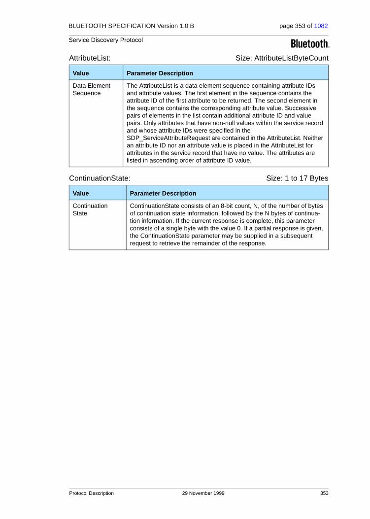
BLUETOOTH SPECIFICATION Version 1.0 B page 353 of 1082
Service Discovery Protocol
AttributeList: Size: AttributeListByteCount
ContinuationState: Size: 1 to 17 Bytes
Value Parameter Description
Data Element Sequence
The AttributeList is a data element sequence containing attribute IDs and attribute values. The first element in the sequence contains the attribute ID of the first attribute to be returned. The second element in the sequence contains the corresponding attribute value. Successive pairs of elements in the list contain additional attribute ID and value pairs. Only attributes that have non-null values within the service record and whose attribute IDs were specified in the SDP_ServiceAttributeRequest are contained in the AttributeList. Neither an attribute ID nor an attribute value is placed in the AttributeList for attributes in the service record that have no value. The attributes are listed in ascending order of attribute ID value.
Value Parameter Description
Continuation State
ContinuationState consists of an 8-bit count, N, of the number of bytes of continuation state information, followed by the N bytes of continua-tion information. If the current response is complete, this parameter consists of a single byte with the value 0. If a partial response is given, the ContinuationState parameter may be supplied in a subsequent request to retrieve the remainder of the response.
Protocol Description 29 November 1999 353

BLUETOOTH SPECIFICATION Version 1.0 B page 354 of 1082
Service Discovery Protocol
4.7 SERVICESEARCHATTRIBUTE TRANSACTION
Figure 4.6:
4.7.1 SDP_ServiceSearchAttributeRequest PDU
Description:
The SDP_ServiceSearchAttributeRequest transaction combines the capabili-ties of the SDP_ServiceSearchRequest and the SDP_ServiceAttributeRequest into a single request. As parameters, it contains both a service search pattern and a list of attributes to be retrieved from service records that match the ser-vice search pattern. The SDP_ServiceSearchAttributeRequest and its response are more complex and may require more bytes than separate SDP_ServiceSearch and SDP_ServiceAttribute transactions. However, using SDP_ServiceSearchAttributeRequest may reduce the total number of SDP transactions, particularly when retrieving multiple service records.
Note that the service record handle for each service record is contained in the ServiceRecordHandle attribute of that service and may be requested along with other attributes.
PDU Type PDU ID Parameters
SDP_ServiceSearchAttributeRequest 0x06 ServiceSearchPattern,MaximumAttributeByteCount,AttributeIDList,ContinuationState
SDP_ServiceSearchAttributeRequest
SDP_ServiceSearchAttributeResponseClient Server
354 29 November 1999 Protocol Description
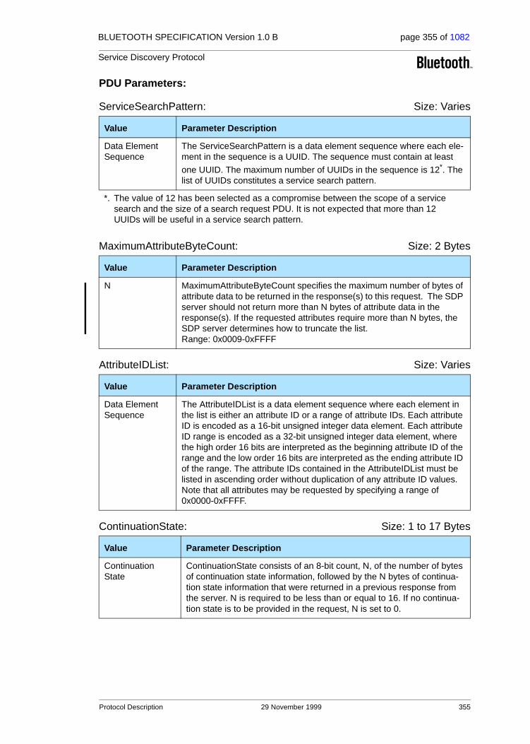
BLUETOOTH SPECIFICATION Version 1.0 B page 355 of 1082
Service Discovery Protocol
PDU Parameters:
ServiceSearchPattern: Size: Varies
MaximumAttributeByteCount: Size: 2 Bytes
AttributeIDList: Size: Varies
ContinuationState: Size: 1 to 17 Bytes
Value Parameter Description
Data Element Sequence
The ServiceSearchPattern is a data element sequence where each ele-ment in the sequence is a UUID. The sequence must contain at least
one UUID. The maximum number of UUIDs in the sequence is 12*. The list of UUIDs constitutes a service search pattern.
*. The value of 12 has been selected as a compromise between the scope of a service search and the size of a search request PDU. It is not expected that more than 12 UUIDs will be useful in a service search pattern.
Value Parameter Description
N MaximumAttributeByteCount specifies the maximum number of bytes of attribute data to be returned in the response(s) to this request. The SDP server should not return more than N bytes of attribute data in the response(s). If the requested attributes require more than N bytes, the SDP server determines how to truncate the list.Range: 0x0009-0xFFFF
Value Parameter Description
Data Element Sequence
The AttributeIDList is a data element sequence where each element in the list is either an attribute ID or a range of attribute IDs. Each attribute ID is encoded as a 16-bit unsigned integer data element. Each attribute ID range is encoded as a 32-bit unsigned integer data element, where the high order 16 bits are interpreted as the beginning attribute ID of the range and the low order 16 bits are interpreted as the ending attribute ID of the range. The attribute IDs contained in the AttributeIDList must be listed in ascending order without duplication of any attribute ID values. Note that all attributes may be requested by specifying a range of 0x0000-0xFFFF.
Value Parameter Description
Continuation State
ContinuationState consists of an 8-bit count, N, of the number of bytes of continuation state information, followed by the N bytes of continua-tion state information that were returned in a previous response from the server. N is required to be less than or equal to 16. If no continua-tion state is to be provided in the request, N is set to 0.
Protocol Description 29 November 1999 355

BLUETOOTH SPECIFICATION Version 1.0 B page 356 of 1082
Service Discovery Protocol
4.7.2 SDP_ServiceSearchAttributeResponse PDU
Description:
The SDP server generates an SDP_ServiceSearchAttributeResponse upon receipt of a valid SDP_ServiceSearchAttributeRequest. The response contains a list of attributes (both attribute ID and attribute value) from the service records that match the requested service search pattern.
PDU Parameters:
AttributeListsByteCount: Size: 2 Bytes
AttributeLists: Size: Varies
PDU Type PDU ID Parameters
SDP_ServiceSearchAttributeResponse 0x07 AttributeListsByteCount,AttributeLists,ContinuationState
Value Parameter Description
N The AttributeListsByteCount contains a count of the number of bytes in the AttributeLists parameter. N must never be larger than the Maximu-mAttributeByteCount value specified in the SDP_ServiceSearchAttributeRequest.
Range: 0x0002-0xFFFF
Value Parameter Description
Data Element Sequence
The AttributeLists is a data element sequence where each element in turn is a data element sequence representing an attribute list. Each attribute list contains attribute IDs and attribute values from one service record. The first element in each attribute list contains the attribute ID of the first attribute to be returned for that service record. The second ele-ment in each attribute list contains the corresponding attribute value. Successive pairs of elements in each attribute list contain additional attribute ID and value pairs. Only attributes that have non-null values within the service record and whose attribute IDs were specified in the SDP_ServiceSearchAttributeRequest are contained in the AttributeLists. Neither an attribute ID nor attribute value is placed in AttributeLists for attributes in the service record that have no value. Within each attribute list, the attributes are listed in ascending order of attribute ID value.
356 29 November 1999 Protocol Description

BLUETOOTH SPECIFICATION Version 1.0 B page 357 of 1082
Service Discovery Protocol
ContinuationState: Size: 1 to 17 Bytes
Value Parameter Description
Continuation State
ContinuationState consists of an 8-bit count, N, of the number of bytes of continuation state information, followed by the N bytes of continua-tion information. If the current response is complete, this parameter consists of a single byte with the value 0. If a partial response is given, the ContinuationState parameter may be supplied in a subsequent request to retrieve the remainder of the response.
Protocol Description 29 November 1999 357

BLUETOOTH SPECIFICATION Version 1.0 B page 358 of 1082
Service Discovery Protocol
5 SERVICE ATTRIBUTE DEFINITIONS
The service classes and attributes contained in this document are necessarily a partial list of the service classes and attributes supported by SDP. Only ser-vice classes that directly support the SDP server are included in this document. Additional service classes will be defined in other documents and possibly in future revisions of this document. Also, it is expected that additional attributes will be discovered that are applicable to a broad set of services; these may be added to the list of Universal attributes in future revisions of this document.
5.1 UNIVERSAL ATTRIBUTE DEFINITIONS
Universal attributes are those service attributes whose definitions are common to all service records. Note that this does not mean that every service record must contain values for all of these service attributes. However, if a service record has a service attribute with an attribute ID allocated to a universal attribute, the attribute value must conform to the universal attribute’s definition.
Only two attributes are required to exist in every service record instance. They are the ServiceRecordHandle (attribute ID 0x0000) and the ServiceClassIDList (attribute ID 0x0001). All other service attributes are optional within a service record.
5.1.1 ServiceRecordHandle Attribute
Description:
A service record handle is a 32-bit number that uniquely identifies each service record within an SDP server. It is important to note that, in general, each han-dle is unique only within each SDP server. If SDP server S1 and SDP server S2 both contain identical service records (representing the same service), the service record handles used to reference these identical service records are completely independent. The handle used to reference the service on S1 will, in general, be meaningless if presented to S2.
Attribute Name Attribute ID Attribute Value Type
ServiceRecordHandle 0x0000 32-bit unsigned integer
358 29 November 1999 Service Attribute Definitions
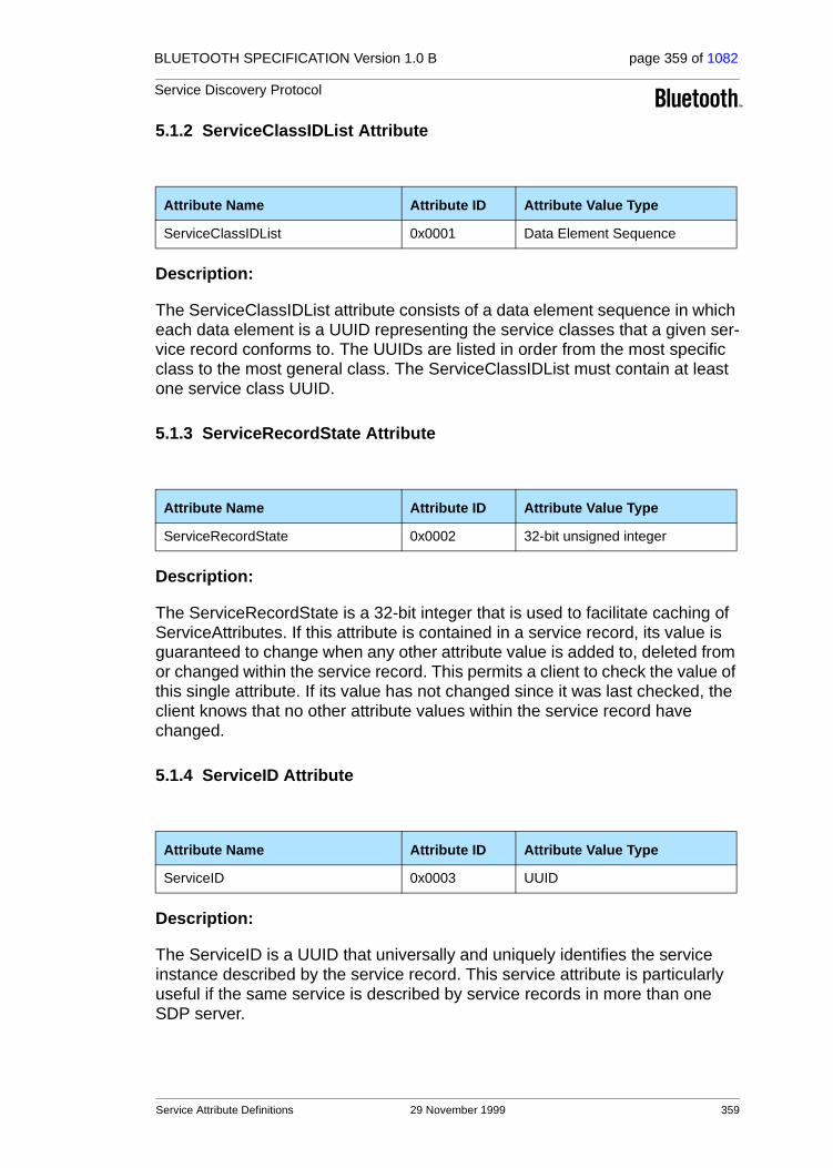
BLUETOOTH SPECIFICATION Version 1.0 B page 359 of 1082
Service Discovery Protocol
5.1.2 ServiceClassIDList Attribute
Description:
The ServiceClassIDList attribute consists of a data element sequence in which each data element is a UUID representing the service classes that a given ser-vice record conforms to. The UUIDs are listed in order from the most specific class to the most general class. The ServiceClassIDList must contain at least one service class UUID.
5.1.3 ServiceRecordState Attribute
Description:
The ServiceRecordState is a 32-bit integer that is used to facilitate caching of ServiceAttributes. If this attribute is contained in a service record, its value is guaranteed to change when any other attribute value is added to, deleted from or changed within the service record. This permits a client to check the value of this single attribute. If its value has not changed since it was last checked, the client knows that no other attribute values within the service record have changed.
5.1.4 ServiceID Attribute
Description:
The ServiceID is a UUID that universally and uniquely identifies the service instance described by the service record. This service attribute is particularly useful if the same service is described by service records in more than one SDP server.
Attribute Name Attribute ID Attribute Value Type
ServiceClassIDList 0x0001 Data Element Sequence
Attribute Name Attribute ID Attribute Value Type
ServiceRecordState 0x0002 32-bit unsigned integer
Attribute Name Attribute ID Attribute Value Type
ServiceID 0x0003 UUID
Service Attribute Definitions 29 November 1999 359
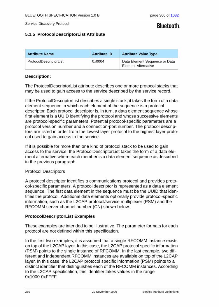
BLUETOOTH SPECIFICATION Version 1.0 B page 360 of 1082
Service Discovery Protocol
5.1.5 ProtocolDescriptorList Attribute
Description:
The ProtocolDescriptorList attribute describes one or more protocol stacks that may be used to gain access to the service described by the service record.
If the ProtocolDescriptorList describes a single stack, it takes the form of a data element sequence in which each element of the sequence is a protocol descriptor. Each protocol descriptor is, in turn, a data element sequence whose first element is a UUID identifying the protocol and whose successive elements are protocol-specific parameters. Potential protocol-specific parameters are a protocol version number and a connection-port number. The protocol descrip-tors are listed in order from the lowest layer protocol to the highest layer proto-col used to gain access to the service.
If it is possible for more than one kind of protocol stack to be used to gain access to the service, the ProtocolDescriptorList takes the form of a data ele-ment alternative where each member is a data element sequence as described in the previous paragraph.
Protocol Descriptors
A protocol descriptor identifies a communications protocol and provides proto-col-specific parameters. A protocol descriptor is represented as a data element sequence. The first data element in the sequence must be the UUID that iden-tifies the protocol. Additional data elements optionally provide protocol-specific information, such as the L2CAP protocol/service multiplexer (PSM) and the RFCOMM server channel number (CN) shown below.
ProtocolDescriptorList Examples
These examples are intended to be illustrative. The parameter formats for each protocol are not defined within this specification.
In the first two examples, it is assumed that a single RFCOMM instance exists on top of the L2CAP layer. In this case, the L2CAP protocol specific information (PSM) points to the single instance of RFCOMM. In the last example, two dif-ferent and independent RFCOMM instances are available on top of the L2CAP layer. In this case, the L2CAP protocol specific information (PSM) points to a distinct identifier that distinguishes each of the RFCOMM instances. According to the L2CAP specification, this identifier takes values in the range 0x1000-0xFFFF.
Attribute Name Attribute ID Attribute Value Type
ProtocolDescriptorList 0x0004 Data Element Sequence or Data Element Alternative
360 29 November 1999 Service Attribute Definitions
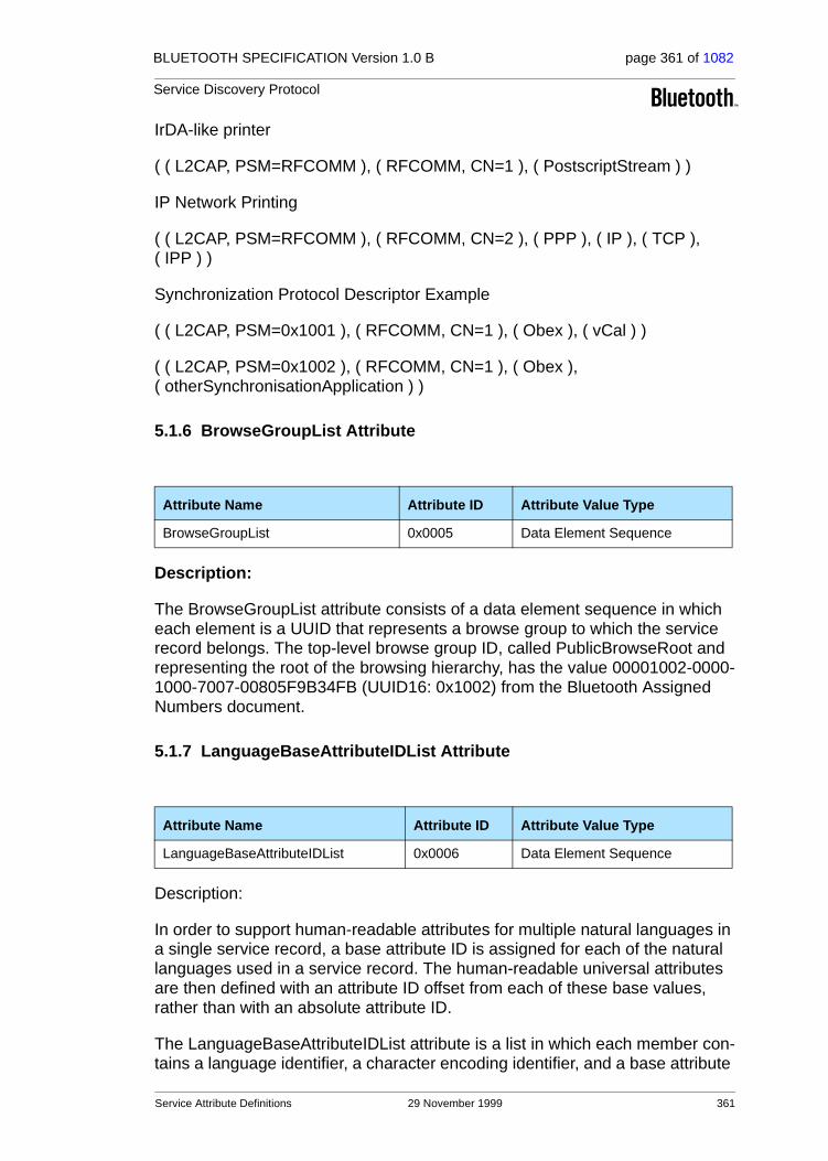
BLUETOOTH SPECIFICATION Version 1.0 B page 361 of 1082
Service Discovery Protocol
IrDA-like printer
( ( L2CAP, PSM=RFCOMM ), ( RFCOMM, CN=1 ), ( PostscriptStream ) )
IP Network Printing
( ( L2CAP, PSM=RFCOMM ), ( RFCOMM, CN=2 ), ( PPP ), ( IP ), ( TCP ), ( IPP ) )
Synchronization Protocol Descriptor Example
( ( L2CAP, PSM=0x1001 ), ( RFCOMM, CN=1 ), ( Obex ), ( vCal ) )
( ( L2CAP, PSM=0x1002 ), ( RFCOMM, CN=1 ), ( Obex ), ( otherSynchronisationApplication ) )
5.1.6 BrowseGroupList Attribute
Description:
The BrowseGroupList attribute consists of a data element sequence in which each element is a UUID that represents a browse group to which the service record belongs. The top-level browse group ID, called PublicBrowseRoot and representing the root of the browsing hierarchy, has the value 00001002-0000-1000-7007-00805F9B34FB (UUID16: 0x1002) from the Bluetooth Assigned Numbers document.
5.1.7 LanguageBaseAttributeIDList Attribute
Description:
In order to support human-readable attributes for multiple natural languages in a single service record, a base attribute ID is assigned for each of the natural languages used in a service record. The human-readable universal attributes are then defined with an attribute ID offset from each of these base values, rather than with an absolute attribute ID.
The LanguageBaseAttributeIDList attribute is a list in which each member con-tains a language identifier, a character encoding identifier, and a base attribute
Attribute Name Attribute ID Attribute Value Type
BrowseGroupList 0x0005 Data Element Sequence
Attribute Name Attribute ID Attribute Value Type
LanguageBaseAttributeIDList 0x0006 Data Element Sequence
Service Attribute Definitions 29 November 1999 361

BLUETOOTH SPECIFICATION Version 1.0 B page 362 of 1082
Service Discovery Protocol
ID for each of the natural languages used in the service record. The Language-BaseAttributeIDList attribute consists of a data element sequence in which each element is a 16-bit unsigned integer. The elements are grouped as triplets (threes).
The first element of each triplet contains an identifier representing the natural language. The language is encoded according to ISO 639:1988 (E/F): “Code for the representation of names of languages”.
The second element of each triplet contains an identifier that specifies a char-acter encoding used for the language. Values for character encoding can be found in IANA's database2, and have the values that are referred to as MIBE-num values. The recommended character encoding is UTF-8.
The third element of each triplet contains an attribute ID that serves as the base attribute ID for the natural language in the service record. Different ser-vice records within a server may use different base attribute ID values for the same language.
To facilitate the retrieval of human-readable universal attributes in a principal language, the base attribute ID value for the primary language supported by a service record must be 0x0100. Also, if a LanguageBaseAttributeIDList attribute is contained in a service record, the base attribute ID value contained in its first element must be 0x0100.
5.1.8 ServiceInfoTimeToLive Attribute
Description:
The ServiceTimeToLive attribute is a 32-bit integer that contains the number of seconds for which the information in a service record is expected to remain valid and unchanged. This time interval is measured from the time that the attribute value is retrieved from the SDP server. This value does not imply a guarantee that the service record will remain available or unchanged. It is simply a hint that a client may use to determine a suitable polling interval to re-validate the service record contents.
2. See http://www.isi.edu/in-notes/iana/assignments/character-sets
Attribute Name Attribute ID Attribute Value Type
ServiceInfoTimeToLive 0x0007 32-bit unsigned integer
362 29 November 1999 Service Attribute Definitions

BLUETOOTH SPECIFICATION Version 1.0 B page 363 of 1082
Service Discovery Protocol
5.1.9 ServiceAvailability Attribute
Description:
The ServiceAvailability attribute is an 8-bit unsigned integer that represents the relative ability of the service to accept additional clients. A value of 0xFF indi-cates that the service is not currently in use and is thus fully available, while a value of 0x00 means that the service is not accepting new clients. For services that support multiple simultaneous clients, intermediate values indicate the rel-ative availability of the service on a linear scale.
For example, a service that can accept up to 3 clients should provide Service-Availability values of 0xFF, 0xAA, 0x55, and 0x00 when 0, 1, 2, and 3 clients, respectively, are utilising the service. The value 0xAA is approximately (2/3) * 0xFF and represents 2/3 availability, while the value 0x55 is approximately (1/3)*0xFF and represents 1/3 availability. Note that the availability value may be approximated as
( 1 - ( current_number_of_clients / maximum_number_of_clients ) ) * 0xFF
When the maximum number of clients is large, this formula must be modified to ensure that ServiceAvailability values of 0x00 and 0xFF are reserved for their defined meanings of unavailability and full availability, respectively.
Note that the maximum number of clients a service can support may vary according to the resources utilised by the service’s current clients.
A non-zero value for ServiceAvailability does not guarantee that the service will be available for use. It should be treated as a hint or an approximation of avail-ability status.
5.1.10 BluetoothProfileDescriptorList Attribute
Description:
The BluetoothProfileDescriptorList attribute consists of a data element sequence in which each element is a profile descriptor that contains informa-tion about a Bluetooth profile to which the service represented by this service record conforms. Each profile descriptor is a data element sequence whose
Attribute Name Attribute ID Attribute Value Type
ServiceAvailability 0x0008 8-bit unsigned integer
Attribute Name Attribute ID Attribute Value Type
BluetoothProfileDescriptorList 0x0009 Data Element Sequence
Service Attribute Definitions 29 November 1999 363

BLUETOOTH SPECIFICATION Version 1.0 B page 364 of 1082
Service Discovery Protocol
first element is the UUID assigned to the profile and whose second element is a 16-bit profile version number.
Each version of a profile is assigned a 16-bit unsigned integer profile version number, which consists of two 8-bit fields. The higher-order 8 bits contain the major version number field and the lower-order 8 bits contain the minor version number field. The initial version of each profile has a major version of 1 and a minor version of 0. When upward compatible changes are made to the profile, the minor version number will be incremented. If incompatible changes are made to the profile, the major version number will be incremented.
5.1.11 DocumentationURL Attribute
Description:
This attribute is a URL which points to documentation on the service described by a service record.
5.1.12 ClientExecutableURL Attribute
Description:
This attribute contains a URL that refers to the location of an application that may be used to utilize the service described by the service record. Since differ-ent operating environments require different executable formats, a mechanism has been defined to allow this single attribute to be used to locate an execut-able that is appropriate for the client device’s operating environment. In the attribute value URL, the first byte with the value 0x2A (ASCII character ‘*’) is to be replaced by the client application with a string representing the desired operating environment before the URL is to be used.
The list of standardized strings representing operating environments is con-tained in the Bluetooth Assigned Numbers document.
For example, assume that the value of the ClientExecutableURL attribute is http://my.fake/public/*/client.exe. On a device capable of executing SH3 Win-dowsCE files, this URL would be changed to http://my.fake/public/sh3-microsoft-wince/client.exe. On a device capable of executing Windows 98 binaries, this URL would be changed to http://my.fake/public/i86-microsoft-win98/client.exe.
Attribute Name Attribute ID Attribute Value Type
DocumentationURL 0x000A URL
Attribute Name Attribute ID Attribute Value Type
ClientExecutableURL 0x000B URL
364 29 November 1999 Service Attribute Definitions

BLUETOOTH SPECIFICATION Version 1.0 B page 365 of 1082
Service Discovery Protocol
5.1.13 IconURL Attribute
Description:
This attribute contains a URL that refers to the location of an icon that may be used to represent the service described by the service record. Since different hardware devices require different icon formats, a mechanism has been defined to allow this single attribute to be used to locate an icon that is appro-priate for the client device. In the attribute value URL, the first byte with the value 0x2A (ASCII character ‘*’) is to be replaced by the client application with a string representing the desired icon format before the URL is to be used.
The list of standardized strings representing icon formats is contained in the Bluetooth Assigned Numbers document.
For example, assume that the value of the IconURL attribute is http://my.fake/public/icons/*. On a device that prefers 24 x 24 icons with 256 colors, this URL would be changed to http://my.fake/public/icons/24x24x8.png. On a device that prefers 10 x 10 monochrome icons, this URL would be changed to http://my.fake/public/icons/10x10x1.png.
5.1.14 ServiceName Attribute
Description:
The ServiceName attribute is a string containing the name of the service repre-sented by a service record. It should be brief and suitable for display with an Icon representing the service. The offset 0x0000 must be added to the attribute ID base (contained in the LanguageBaseAttributeIDList attribute) in order to compute the attribute ID for this attribute.
Attribute Name Attribute ID Attribute Value Type
IconURL 0x000C URL
Attribute Name Attribute ID Offset Attribute Value Type
ServiceName 0x0000 String
Service Attribute Definitions 29 November 1999 365
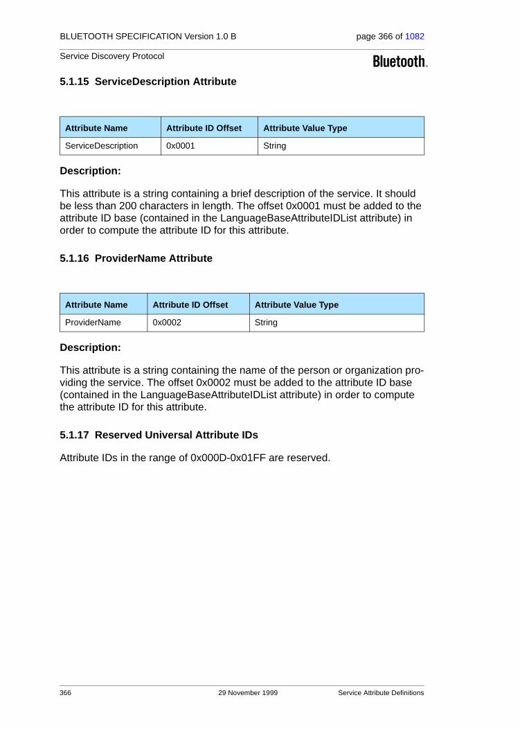
BLUETOOTH SPECIFICATION Version 1.0 B page 366 of 1082
Service Discovery Protocol
5.1.15 ServiceDescription Attribute
Description:
This attribute is a string containing a brief description of the service. It should be less than 200 characters in length. The offset 0x0001 must be added to the attribute ID base (contained in the LanguageBaseAttributeIDList attribute) in order to compute the attribute ID for this attribute.
5.1.16 ProviderName Attribute
Description:
This attribute is a string containing the name of the person or organization pro-viding the service. The offset 0x0002 must be added to the attribute ID base (contained in the LanguageBaseAttributeIDList attribute) in order to compute the attribute ID for this attribute.
5.1.17 Reserved Universal Attribute IDs
Attribute IDs in the range of 0x000D-0x01FF are reserved.
Attribute Name Attribute ID Offset Attribute Value Type
ServiceDescription 0x0001 String
Attribute Name Attribute ID Offset Attribute Value Type
ProviderName 0x0002 String
366 29 November 1999 Service Attribute Definitions

BLUETOOTH SPECIFICATION Version 1.0 B page 367 of 1082
Service Discovery Protocol
5.2 SERVICEDISCOVERYSERVER SERVICE CLASS ATTRIBUTE DEFINITIONS
This service class describes service records that contain attributes of service discovery server itself. The attributes listed in this section are only valid if the ServiceClassIDList attribute contains the ServiceDiscoveryServerServiceClassID. Note that all of the universal attributes may be included in service records of the ServiceDiscoveryServer class.
5.2.1 ServiceRecordHandle Attribute
Described in the universal attribute definition for ServiceRecordHandle.
Value
A 32-bit integer with the value 0x000000000.
5.2.2 ServiceClassIDList Attribute
Described in the universal attribute definition for ServiceClassIDList.
Value
A UUID representing the ServiceDiscoveryServerServiceClassID.
5.2.3 VersionNumberList Attribute
Description:
The VersionNumberList is a data element sequence in which each element of the sequence is a version number supported by the SDP server.
A version number is a 16-bit unsigned integer consisting of two fields. The higher-order 8 bits contain the major version number field and the low-order 8 bits contain the minor version number field. The initial version of SDP has a major version of 1 and a minor version of 0. When upward compatible changes are made to the protocol, the minor version number will be incremented. If incompatible changes are made to SDP, the major version number will be incremented. This guarantees that if a client and a server support a common major version number, they can communicate if each uses only features of the specification with a minor version number that is supported by both client and server.
Attribute Name Attribute ID Attribute Value Type
VersionNumberList 0x0200 Data Element Sequence
Service Attribute Definitions 29 November 1999 367

BLUETOOTH SPECIFICATION Version 1.0 B page 368 of 1082
Service Discovery Protocol
5.2.4 ServiceDatabaseState Attribute
Description:
The ServiceDatabaseState is a 32-bit integer that is used to facilitate caching of service records. If this attribute exists, its value is guaranteed to change when any of the other service records are added to or deleted from the server’s database. If this value has not changed since the last time a client queried its value, the client knows that a) none of the other service records maintained by the SDP server have been added or deleted; and b) any service record han-dles acquired from the server are still valid. A client should query this attribute’s value when a connection to the server is established, prior to using any service record handles acquired during a previous connection.
Note that the ServiceDatabaseState attribute does not change when existing service records are modified, including the addition, removal, or modification of service attributes. A service record’s ServiceRecordState attribute indicates when that service record is modified.
5.2.5 Reserved Attribute IDs
Attribute IDs in the range of 0x0202-0x02FF are reserved.
Attribute Name Attribute ID Attribute Value Type
ServiceDatabaseState 0x0201 32-bit unsigned integer
368 29 November 1999 Service Attribute Definitions
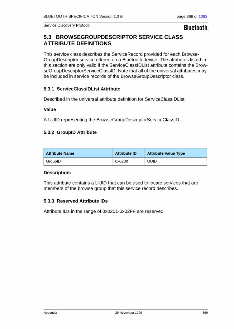
BLUETOOTH SPECIFICATION Version 1.0 B page 369 of 1082
Service Discovery Protocol
5.3 BROWSEGROUPDESCRIPTOR SERVICE CLASS ATTRIBUTE DEFINITIONS
This service class describes the ServiceRecord provided for each Browse-GroupDescriptor service offered on a Bluetooth device. The attributes listed in this section are only valid if the ServiceClassIDList attribute contains the Brow-seGroupDescriptorServiceClassID. Note that all of the universal attributes may be included in service records of the BrowseGroupDescriptor class.
5.3.1 ServiceClassIDList Attribute
Described in the universal attribute definition for ServiceClassIDList.
Value
A UUID representing the BrowseGroupDescriptorServiceClassID.
5.3.2 GroupID Attribute
Description:
This attribute contains a UUID that can be used to locate services that are members of the browse group that this service record describes.
5.3.3 Reserved Attribute IDs
Attribute IDs in the range of 0x0201-0x02FF are reserved.
6 APPENDIX
Attribute Name Attribute ID Attribute Value Type
GroupID 0x0200 UUID
Appendix 29 November 1999 369

BLUETOOTH SPECIFICATION Version 1.0 B page 370 of 1082
Service Discovery Protocol
APPENDIX A – BACKGROUND INFORMATION
A.1. Service Discovery
As computing continues to move to a network-centric model, finding and mak-ing use of services that may be available in the network becomes increasingly important. Services can include common ones such as printing, paging, FAX-ing, and so on, as well as various kinds of information access such as telecon-ferencing, network bridges and access points, eCommerce facilities, and so on — most any kind of service that a server or service provider might offer. In addition to the need for a standard way of discovering available services, there are other considerations: getting access to the services (finding and obtaining the protocols, access methods, “drivers” and other code necessary to utilize the service), controlling access to the services, advertising the services, choos-ing among competing services, billing for services, and so on. This problem is widely recognized; many companies, standards bodies and consortia are addressing it at various levels in various ways. Service Location Protocol (SLP), JiniTM, and SalutationTM, to name just a few, all address some aspect of service discovery.
A.2. Bluetooth Service Discovery
Bluetooth Service Discovery Protocol (SDP) addresses service discovery spe-cifically for the Bluetooth environment. It is optimized for the highly dynamic nature of Bluetooth communications. SDP focuses primarily on discovering services available from or through Bluetooth devices. SDP does not define methods for accessing services; once services are discovered with SDP, they can be accessed in various ways, depending upon the service. This might include the use of other service discovery and access mechanisms such as those mentioned above; SDP provides a means for other protocols to be used along with SDP in those environments where this can be beneficial. While SDP can coexist with other service discovery protocols, it does not require them. In Bluetooth environments, services can be discovered using SDP and can be accessed using other protocols defined by Bluetooth.
370 29 November 1999 Appendix

BLUETOOTH SPECIFICATION Version 1.0 B page 371 of 1082
Service Discovery Protocol
APPENDIX B – EXAMPLE SDP TRANSACTIONS
The following are simple examples of typical SDP transactions. These are meant to be illustrative of SDP flows. The examples do not consider:
• Caching (in a caching system, the SDP client would make use of the ServiceRecordState and ServiceDatabaseState attributes);
• Service availability (if this is of interest, the SDP client should use the ServiceAvailability and/or ServiceTimeToLive attributes);
• SDP versions (the VersionNumberList attribute could be used to determine compatible SDP versions);
• SDP Error Responses (an SDP error response is possible for any SDP request that is in error); and
• Communication connection (the examples assume that an L2CAP connection is established).
The examples are meant to be illustrative of the protocol. The format used is ObjectName[ObjectSizeInBytes] {SubObjectDefinitions}, but this is not meant to illustrate an interface. The ObjectSizeInBytes is the size of the object in decimal. The SubObjectDefinitions (inside of {} characters) are compo-nents of the immediately enclosing object. Hexadecimal values shown as lower-case letters, such as for transaction IDs and service handles, are vari-ables (the particular value is not important for the illustration, but each such symbol always represents the same value). Comments are included in this manner: /* comment text */.
B.1. SDP Example 1 – ServiceSearchRequest
The first example is that of an SDP client searching for a generic printing ser-vice. The client does not specify a particular type of printing service. In the example, the SDP server has two available printing services. The transaction illustrates:
1. SDP client to SDP server: SDP_ServiceSearchRequest, specifying the PrinterServiceClassID (represented as a DataElement with a 32-bit UUID value of ppp...ppp) as the only element of the ServiceSearchPattern. The PrinterServiceClassID is assumed to be a 32-bit UUID and the data element type for it is illustrated. The TransactionID is illustrated as tttt.
2. SDP server to SDP client: SDP_ServiceSearchResponse, returning handles to two printing services, represented as qqqqqqqq for the first printing ser-vice and rrrrrrrr for the second printing service. The Transaction ID is the same value as supplied by the SDP client in the corresponding request (ττττ ).
/* Sent from SDP Client to SDP server */SDP_ServiceSearchRequest[15] { PDUID[1] {
Appendix 29 November 1999 371

BLUETOOTH SPECIFICATION Version 1.0 B page 372 of 1082
Service Discovery Protocol
0x02 } TransactionID[2] { 0xtttt } ParameterLength[2] { 0x000A } ServiceSearchPattern[7] { DataElementSequence[7] { 0b00110 0b101 0x05 UUID[5] { /* PrinterServiceClassID */ 0b00011 0b010 0xpppppppp } } } MaximumServiceRecordCount[2] { 0x0003 } ContinuationState[1] { /* no continuation state */ 0x00 }}
/* Sent from SDP server to SDP client */SDP_ServiceSearchResponse[16] { PDUID[1] { 0x03 } TransactionID[2] { 0xtttt } ParameterLength[2] { 0x000D } TotalServiceRecordCount[2] { 0x0002 } CurrentServiceRecordCount[2] { 0x0002 } ServiceRecordHandleList[8] { /* print service 1 handle */ 0xqqqqqqqq /* print service 2 handle */ 0xrrrrrrrr } ContinuationState[1] { /* no continuation state */ 0x00 }}
372 29 November 1999 Appendix
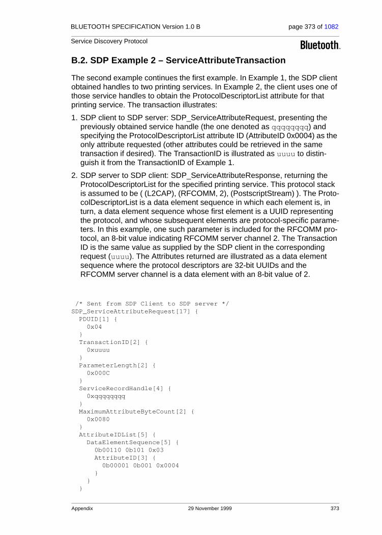
BLUETOOTH SPECIFICATION Version 1.0 B page 373 of 1082
Service Discovery Protocol
B.2. SDP Example 2 – ServiceAttributeTransaction
The second example continues the first example. In Example 1, the SDP client obtained handles to two printing services. In Example 2, the client uses one of those service handles to obtain the ProtocolDescriptorList attribute for that printing service. The transaction illustrates:
1. SDP client to SDP server: SDP_ServiceAttributeRequest, presenting the previously obtained service handle (the one denoted as qqqqqqqq) and specifying the ProtocolDescriptorList attribute ID (AttributeID 0x0004) as the only attribute requested (other attributes could be retrieved in the same transaction if desired). The TransactionID is illustrated as uuuu to distin-guish it from the TransactionID of Example 1.
2. SDP server to SDP client: SDP_ServiceAttributeResponse, returning the ProtocolDescriptorList for the specified printing service. This protocol stack is assumed to be ( (L2CAP), (RFCOMM, 2), (PostscriptStream) ). The Proto-colDescriptorList is a data element sequence in which each element is, in turn, a data element sequence whose first element is a UUID representing the protocol, and whose subsequent elements are protocol-specific parame-ters. In this example, one such parameter is included for the RFCOMM pro-tocol, an 8-bit value indicating RFCOMM server channel 2. The Transaction ID is the same value as supplied by the SDP client in the corresponding request (uuuu). The Attributes returned are illustrated as a data element sequence where the protocol descriptors are 32-bit UUIDs and the RFCOMM server channel is a data element with an 8-bit value of 2.
/* Sent from SDP Client to SDP server */SDP_ServiceAttributeRequest[17] { PDUID[1] { 0x04 } TransactionID[2] { 0xuuuu } ParameterLength[2] { 0x000C } ServiceRecordHandle[4] { 0xqqqqqqqq } MaximumAttributeByteCount[2] { 0x0080 } AttributeIDList[5] { DataElementSequence[5] { 0b00110 0b101 0x03 AttributeID[3] { 0b00001 0b001 0x0004 } } }
Appendix 29 November 1999 373

BLUETOOTH SPECIFICATION Version 1.0 B page 374 of 1082
Service Discovery Protocol
ContinuationState[1] { /* no continuation state */ 0x00 }}
/* Sent from SDP server to SDP client */SDP_ServiceAttributeResponse[36] { PDUID[1] { 0x05 } TransactionID[2] { 0xuuuu } ParameterLength[2] { 0x0021 } AttributeListByteCount[2] { 0x001E } AttributeList[30] { DataElementSequence[30] { 0b00110 0b101 0x1C Attribute[28] { AttributeID[3] { 0b00001 0b001 0x0004 } AttributeValue[25] { /* ProtocolDescriptorList */ DataElementSequence[25] { 0b00110 0b101 0x17 /* L2CAP protocol descriptor */ DataElementSequence[7] { 0b00110 0b101 0x05 UUID[5] { /* L2CAP Protocol UUID */ 0b00011 0b010 <32-bit L2CAP UUID> } } /* RFCOMM protocol descriptor */ DataElementSequence[9] { 0b00110 0b101 0x07 UUID[5] { /* RFCOMM Protocol UUID */ 0b00011 0b010 <32-bit RFCOMM UUID> } /* parameter for server 2 */ Uint8[2] { 0b00001 0b000 0x02 } } /* PostscriptStream protocol descriptor */ DataElementSequence[7] { 0b00110 0b101 0x05 UUID[5] { /* PostscriptStream Protocol UUID */ 0b00011 0b010 <32-bit PostscriptStream UUID>
374 29 November 1999 Appendix

BLUETOOTH SPECIFICATION Version 1.0 B page 375 of 1082
Service Discovery Protocol
} } } } } } } ContinuationState[1] { /* no continuation state */ 0x00 }}
Appendix 29 November 1999 375

BLUETOOTH SPECIFICATION Version 1.0 B page 376 of 1082
Service Discovery Protocol
B.3. SDP Example 3 – ServiceSearchAttributeTransaction
The third example is a form of service browsing, although it is not generic browsing in that it does not make use of SDP browse groups. Instead, an SDP client is searching for available Synchronization services that can be presented to the user for selection. The SDP client does not specify a particular type of synchronization service. In the example, the SDP server has three available synchronization services: an address book synchronization service and a cal-endar synchronization service (both from the same provider), and a second calendar synchronization service from a different provider. The SDP client is retrieving the same attributes for each of these services; namely, the data for-mats supported for the synchronization service (vCard, vCal, ICal, etc.) and those attributes that are relevant for presenting information to the user about the services. Also assume that the maximum size of a response is 400 bytes. Since the result is larger than this, the SDP client will repeat the request sup-plying a continuation state parameter to retrieve the remainder of the response. The transaction illustrates:
1. SDP client to SDP server: SDP_ServiceSearchAttributeRequest, specifying the generic SynchronisationServiceClassID (represented as a data element whose 32-bit UUID value is sss...sss) as the only element of the Service-SearchPattern. The SynchronisationServiceClassID is assumed to be a 32-bit UUID. The requested attributes are the ServiceRecordHandle (attribute ID 0x0000), ServiceClassIDList (attribute ID 0x0001), IconURL (attribute ID 0x000C), ServiceName (attribute ID 0x0100), ServiceDescription (attribute ID 0x0101), and ProviderName (attributeID 0x0102) attributes; as well as the service-specific SupportedDataStores (AttributeID 0x0301). Since the first two attribute IDs (0x0000 and 0x0001) and three other attribute IDs(0x0100, 0x0101, and 0x0102 are consecutive, they are specified as attribute ranges. The TransactionID is illustrated as vvvv to distinguish it from the TransactionIDs of the other Examples.
Note that values in the service record’s primary language are requested for the text attributes (ServiceName, ServiceDescription and ProviderName) so that absolute attribute IDs may be used, rather than adding offsets to a base obtained from the LanguageBaseAttributeIDList attribute.
2. SDP server to SDP client: SDP_ServiceSearchAttributeResponse, returning the specified attributes for each of the three synchronization services. In the example, each ServiceClassIDList is assumed to contain a single element, the generic SynchronisationServiceClassID (a 32-bit UUID represented as sss...sss). Each of the other attributes contain illustrative data in the exam-ple (the strings have illustrative text; the icon URLs are illustrative, for each of the respective three synchronization services; and the SupportedDataS-tore attribute is represented as an unsigned 8-bit integer where 0x01 = vCard2.1, 0x02 = vCard3.0, 0x03 = vCal1.0 and 0x04 = iCal). Note that one of the service records (the third for which data is returned) has no Service-Description attribute. The attributes are returned as a data element sequence, where each element is in turn a data element sequence repre-
376 29 November 1999 Appendix

BLUETOOTH SPECIFICATION Version 1.0 B page 377 of 1082
Service Discovery Protocol
senting a list of attributes. Within each attribute list, the ServiceClassIDList is a data element sequence while the remaining attributes are single data ele-ments. The Transaction ID is the same value as supplied by the SDP client in the corresponding request (ϖϖϖϖ). Since the entire result cannot be returned in a single response, a non-null continuation state is returned in this first response.
Note that the total length of the initial data element sequence (487 in the example) is indicated in the first response, even though only a portion of this data element sequence (368 bytes in the example, as indicated in the AttributeLists byte count) is returned in the first response. The remainder of this data element sequence is returned in the second response (without an additional data element header).
3. SDP client to SDP server: SDP_ServiceSearchAttributeRequest, with the same parameters as in step 1, except that the continuation state received from the server in step 2 is included as a request parameter. The Transac-tionID is changed to ωωωω to distinguish it from previous request.
4. SDP server to SDP client: SDP_ServiceSearchAttributeResponse, with the remainder of the result computed in step 2 above. Since all of the remaining result fits in this second response, a null continuation state is included.
/* Part 1 -- Sent from SDP Client to SDP server */SdpSDP_ServiceSearchAttributeRequest[33] { PDUID[1] { 0x06 } TransactionID[2] { 0xvvvv } ParameterLength[2] { 0x001B } ServiceSearchPattern[7] { DataElementSequence[7] { 0b00110 0b101 0x05 UUID[5] { /* SynchronisationServiceClassID */ 0b00011 0b010 0xssssssss } } } MaximumAttributeByteCount[2] { 0x0190 }AttributeIDList[18] { DataElementSequence[18] { 0b00110 0b101 0x10 AttributeIDRange[5] { 0b00001 0b010 0x00000001 } AttributeID[3] { 0b00001 0b001 0x000C
Appendix 29 November 1999 377

BLUETOOTH SPECIFICATION Version 1.0 B page 378 of 1082
Service Discovery Protocol
} AttributeIDRange[5] { 0b00001 0b010 0x01000102 } AttributeID[3] { 0b00001 0b001 0x0301 } } } ContinuationState[1] { /* no continuation state */ 0x00 }}
/* Part 2 -- Sent from SDP server to SDP client */SdpSDP_ServiceSearchAttributeResponse[384] { PDUID[1] { 0x07 } TransactionID[2] { 0xvvvv } ParameterLength[2] { 0x017B } AttributeListByteCount[2] { 0x0170 } AttributeLists[368] { DataElementSequence[487] { 0b00110 0b110 0x01E4 DataElementSequence[178] { 0b00110 0b101 0xB0 Attribute[8] { AttributeID[3] { 0b00001 0b001 0x0000 } AttributeValue[5] { /* service record handle */ 0b00001 0b010 0xhhhhhhhh } } Attribute[10] { AttributeID[3] { 0b00001 0b001 0x0001 }AttributeValue[7] { DataElementSequence[7] { 0b00110 0b101 0x05 UUID[5] { /* SynchronisationServiceClassID */ 0b00011 0b010 0xssssssss } } } } Attribute[35] {
378 29 November 1999 Appendix

BLUETOOTH SPECIFICATION Version 1.0 B page 379 of 1082
Service Discovery Protocol
AttributeID[3] { 0b00001 0b001 0x000C } AttributeValue[32] { /* IconURL; ’*’ replaced by client application */ 0b01000 0b101 0x1E "http://Synchronisation/icons/*" } } Attribute[22] { AttributeID[3] { 0b00001 0b001 0x0100 } AttributeValue[19] { /* service name */ 0b00100 0b101 0x11 "Address Book Sync" } } Attribute[59] { AttributeID[3] { 0b00001 0b001 0x0101 } AttributeValue[56] { /* service description */ 0b00100 0b101 0x36 "Synchronisation Service for" " vCard Address Book Entries" } } Attribute[37] { AttributeID[3] { 0b00001 0b001 0x0102 } AttributeValue[34] { /* service provider */ 0b00100 0b101 0x20 "Synchronisation Specialists Inc." } } Attribute[5] { AttributeID[3] { 0b00001 0b001 0x0301 } AttributeValue[2] { /* Supported Data Store ’phonebook’ */ 0b00001 0b000 0x01 } } } DataElementSequence[175] { 0b00110 0b101 0xAD Attribute[8] { AttributeID[3] { 0b00001 0b001 0x0000 } AttributeValue[5] {
Appendix 29 November 1999 379

BLUETOOTH SPECIFICATION Version 1.0 B page 380 of 1082
Service Discovery Protocol
/* service record handle */ 0b00001 0b010 0xmmmmmmmm } } Attribute[10] { AttributeID[3] { 0b00001 0b001 0x0001 } AttributeValue[7] { DataElementSequence[7] { 0b00110 0b101 0x05 UUID[5] { /* SynchronisationServiceClassID */ 0b00011 0b010 0xssssssss } } } } Attribute[35] { AttributeID[3] { 0b00001 0b001 0x000C } AttributeValue[32] { /* IconURL; ’*’ replaced by client application */ 0b01000 0b101 0x1E "http://Synchronisation/icons/*" } } Attribute[21] { AttributeID[3] { 0b00001 0b001 0x0100 } AttributeValue[18] { /* service name */ 0b00100 0b101 0x10 "Appointment Sync" } } Attribute[57] { AttributeID[3] { 0b00001 0b001 0x0101 } AttributeValue[54] { /* service description */ 0b00100 0b101 0x34 "Synchronisation Service for" " vCal Appointment Entries" } } Attribute[37] { AttributeID[3] { 0b00001 0b001 0x0102 } AttributeValue[34] { /* service provider */ 0b00100 0b101 0x20 "Synchronisation Specialists Inc."
380 29 November 1999 Appendix

BLUETOOTH SPECIFICATION Version 1.0 B page 381 of 1082
Service Discovery Protocol
} } Attribute[5] { AttributeID[3] { 0b00001 0b001 0x0301 } AttributeValue[2] { /* Supported Data Store ’calendar’ */ 0b00001 0b000 0x03 } } } /* } Data element sequence of attribute lists */ /* is not completed in this PDU. */ } ContinuationState[9] { /* 8 bytes of continuation state */ 0x08 0xzzzzzzzzzzzzzzzz }}
/* Part 3 -- Sent from SDP Client to SDP server */SdpSDP_ServiceSearchAttributeRequest[41] { PDUID[1] { 0x06 } TransactionID[2] { 0xwwww } ParameterLength[2] { 0x0024 } ServiceSearchPattern[7] { DataElementSequence[7] { 0b00110 0b101 0x05 UUID[5] { /* SynchronisationServiceClassID */ 0b00011 0b010 0xssssssss } } } MaximumAttributeByteCount[2] { 0x0180 } AttributeIDList[18] { DataElementSequence[18] { 0b00110 0b101 0x10 AttributeIDRange[5] { 0b00001 0b010 0x00000001 } AttributeID[3] { 0b00001 0b001 0x000C } AttributeIDRange[5] { 0b00001 0b010 0x01000102 } AttributeID[3] {
Appendix 29 November 1999 381

BLUETOOTH SPECIFICATION Version 1.0 B page 382 of 1082
Service Discovery Protocol
0b00001 0b001 0x0301 } } } ContinuationState[9] { /* same 8 bytes of continuation state */ /* received in part 2 */ 0x08 0xzzzzzzzzzzzzzzzz }}
Part 4 -- Sent from SDP server to SDP client SdpSDP_ServiceSearchAttributeResponse[115] { PDUID[1] { 0x07 } TransactionID[2] { 0xwwww } ParameterLength[2] { 0x006E } AttributeListByteCount[2] { 0x006B } AttributeLists[107] { /* Continuing the data element sequence of */ /* attribute lists begun in Part 2. */ DataElementSequence[107] { 0b00110 0b101 0x69 Attribute[8] { AttributeID[3] { 0b00001 0b001 0x0000 } AttributeValue[5] { /* service record handle */ 0b00001 0b010 0xffffffff } } Attribute[10] { AttributeID[3] { 0b00001 0b001 0x0001 } AttributeValue[7] { DataElementSequence[7] { 0b00110 0b101 0x05 UUID[5] { /* SynchronisationServiceClassID */ 0b00011 0b010 0xssssssss } } } } Attribute[35] { AttributeID[3] { 0b00001 0b001 0x000C
382 29 November 1999 Appendix

BLUETOOTH SPECIFICATION Version 1.0 B page 383 of 1082
Service Discovery Protocol
} AttributeValue[32] { /* IconURL; ’*’ replaced by client application */ 0b01000 0b101 0x1E "http://DevManufacturer/icons/*" } } Attribute[18] { AttributeID[3] { 0b00001 0b001 0x0100 } AttributeValue[15] { /* service name */ 0b00100 0b101 0x0D "Calendar Sync" } } Attribute[29] { AttributeID[3] { 0b00001 0b001 0x0102 } AttributeValue[26] { /* service provider */ 0b00100 0b101 0x18 "Device Manufacturer Inc." } } Attribute[5] { AttributeID[3] { 0b00001 0b001 0x0301 } AttributeValue[2] { /* Supported Data Store ’calendar’ */ 0b00001 0b000 0x03 } } } /* This completes the data element sequence */ /* of attribute lists begun in Part 2. } ContinuationState[1] { /* no continuation state */ 0x00 }}
Appendix 29 November 1999 383

BLUETOOTH SPECIFICATION Version 1.0 B page 384 of 1082
Service Discovery Protocol
384 29 November 1999 Appendix

Part F:1
RFCOMM with TS 07.10
Serial Port Emulation
This document specifies the RFCOMM proto-col by specifying a subset of the ETSI TS 07.10 standard, along with some Bluetooth-specific adaptations

BLUETOOTH SPECIFICATION Version 1.0 B page 386 of 1082
RFCOMM with TS 07.10
386 29 November 1999

BLUETOOTH SPECIFICATION Version 1.0 B page 387 of 1082
RFCOMM with TS 07.10
CONTENTS
1 Introduction ......................................................................................3891.1 Overview ..................................................................................3891.2 Device Types ...........................................................................3891.3 Byte Ordering...........................................................................390
2 RFCOMM Service Overview ............................................................3912.1 RS-232 Control Signals............................................................3912.2 Null Modem Emulation.............................................................3912.3 Multiple Emulated Serial Ports.................................................393
2.3.1 Multiple Emulated Serial Ports between two Devices .393
2.3.2 Multiple Emulated Serial Ports and Multiple BT Devices........................................................................393
3 Service Interface Description..........................................................3953.1 Service Definition Model ..........................................................395
4 TS 07.10 Subset Supported by RFCOMM ......................................3964.1 Options and Modes..................................................................3964.2 Frame Types ............................................................................3964.3 Commands...............................................................................3964.4 Convergence Layers................................................................397
5 TS 07.10 Adaptations for RFCOMM................................................3985.1 Media Adaptation .....................................................................398
5.1.1 FCS calculation ...........................................................398
5.2 TS 07.10 Multiplexer Start-up and Closedown Procedure.......3995.2.1 Start-up procedure ......................................................399
5.2.2 Close-down procedure ................................................399
5.2.3 Link loss handling........................................................399
5.3 System Parameters..................................................................4005.4 DLCI allocation with RFCOMM server channels......................4005.5 Multiplexer Control Commands................................................401
5.5.1 Remote Port Negotiation Command (RPN) ................401
5.5.2 Remote Line Status Command (RLS).........................402
5.5.3 DLC parameter negotiation (PN).................................402
6 Flow Control .....................................................................................4036.1 L2CAP Flow Control in Overview.............................................4036.2 Wired Serial Port Flow Control.................................................4036.3 RFCOMM Flow Control............................................................4036.4 Port Emulation Entity Serial Flow Control ................................403
29 November 1999 387
BLUETOOTH SPECIFICATION Version 1.0 B page 388 of 1082
RFCOMM with TS 07.10
7 Interaction with Other Entities........................................................4057.1 Port Emulation and Port Proxy Entities....................................405
7.1.1 Port Emulation Entity...................................................405
7.1.2 Port Proxy Entity .........................................................405
7.2 Service Registration and Discovery.........................................4057.3 Lower Layer Dependencies .....................................................407
7.3.1 Reliability.....................................................................407
7.3.2 Low power modes.......................................................407
8 References........................................................................................408
9 Terms and Abbreviations ................................................................409
388 29 November 1999
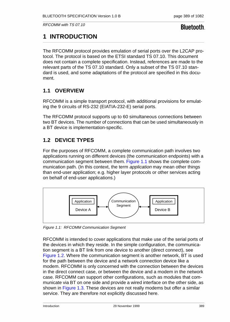
BLUETOOTH SPECIFICATION Version 1.0 B page 389 of 1082
RFCOMM with TS 07.10
1 INTRODUCTION
The RFCOMM protocol provides emulation of serial ports over the L2CAP pro-tocol. The protocol is based on the ETSI standard TS 07.10. This document does not contain a complete specification. Instead, references are made to the relevant parts of the TS 07.10 standard. Only a subset of the TS 07.10 stan-dard is used, and some adaptations of the protocol are specified in this docu-ment.
1.1 OVERVIEW
RFCOMM is a simple transport protocol, with additional provisions for emulat-ing the 9 circuits of RS-232 (EIATIA-232-E) serial ports.
The RFCOMM protocol supports up to 60 simultaneous connections between two BT devices. The number of connections that can be used simultaneously in a BT device is implementation-specific.
1.2 DEVICE TYPES
For the purposes of RFCOMM, a complete communication path involves two applications running on different devices (the communication endpoints) with a communication segment between them. Figure 1.1 shows the complete com-munication path. (In this context, the term application may mean other things than end-user application; e.g. higher layer protocols or other services acting on behalf of end-user applications.)
Figure 1.1: RFCOMM Communication Segment
RFCOMM is intended to cover applications that make use of the serial ports of the devices in which they reside. In the simple configuration, the communica-tion segment is a BT link from one device to another (direct connect), see Figure 1.2. Where the communication segment is another network, BT is used for the path between the device and a network connection device like a modem. RFCOMM is only concerned with the connection between the devices in the direct connect case, or between the device and a modem in the network case. RFCOMM can support other configurations, such as modules that com-municate via BT on one side and provide a wired interface on the other side, as shown in Figure 1.3. These devices are not really modems but offer a similar service. They are therefore not explicitly discussed here.
Application
Device A
Application
Device B
CommunicationSegment
Introduction 29 November 1999 389

BLUETOOTH SPECIFICATION Version 1.0 B page 390 of 1082
RFCOMM with TS 07.10
Basically two device types exist that RFCOMM must accommodate. Type 1 devices are communication end points such as computers and printers. Type 2 devices are those that are part of the communication segment; e.g. modems. Though RFCOMM does not make a distinction between these two device types in the protocol, accommodating both types of devices impacts the RFCOMM protocol.
Figure 1.2: RFCOMM Direct Connect
Figure 1.3: RFCOMM used with legacy COMM device
The information transferred between two RFCOMM entities has been defined to support both type 1 and type 2 devices. Some information is only needed by type 2 devices while other information is intended to be used by both. In the protocol, no distinction is made between type 1 and type 2. It is therefore up to the RFCOMM implementers to determine if the information passed in the RFCOMM protocol is of use to the implementation. Since the device is not aware of the type of the other device in the communication path, each must pass on all available information specified by the protocol.
1.3 BYTE ORDERING
This document uses the same byte ordering as the TS 07.10 specification; i.e. all binary numbers are in Least Significant Bit to Most Significant Bit order, reading from left to right.
Device Awith BT(Type 1)
Device Bwith BT(Type 1)
BT
Device Awith BT(Type 1)
Device Bwith BT(Type 2)
Device Cnon BT
BT Wire
390 29 November 1999 Introduction

BLUETOOTH SPECIFICATION Version 1.0 B page 391 of 1082
RFCOMM with TS 07.10
2 RFCOMM SERVICE OVERVIEW
RFCOMM emulates RS-232 (EIATIA-232-E) serial ports. The emulation includes transfer of the state of the non-data circuits. RFCOMM has a built-in scheme for null modem emulation.
In the event that a baud rate is set for a particular port through the RFCOMM service interface, that will not affect the actual data throughput in RFCOMM; i.e. RFCOMM does not incur artificial rate limitation or pacing. However, if either device is a type 2 device (relays data onto other media), or if data pacing is done above the RFCOMM service interface in either or both ends, actual throughput will, on an average, reflect the baud rate setting.
RFCOMM supports emulation of multiple serial ports between two devices and also emulation of serial ports between multiple devices, see Section 2.3 on page 393.
2.1 RS-232 CONTROL SIGNALS
RFCOMM emulates the 9 circuits of an RS-232 interface. The circuits are listed below.
2.2 NULL MODEM EMULATION
RFCOMM is based on TS 07.10. When it comes to transfer of the states of the non-data circuits, TS 07.10 does not distinguish between DTE and DCE devices. The RS-232 control signals are sent as a number of DTE/DCE inde-pendent signals, see Table 2.2.
Pin Circuit Name
102 Signal Common
103 Transmit Data (TD)
104 Received Data (RD)
105 Request to Send (RTS)
106 Clear to Send (CTS)
107 Data Set Ready (DSR)
108 Data Terminal Ready (DTR)
109 Data Carrier Detect (CD)
125 Ring Indicator (RI)
Table 2.1: Emulated RS-232 circuits in RFCOMM
RFCOMM Service Overview 29 November 1999 391

BLUETOOTH SPECIFICATION Version 1.0 B page 392 of 1082
RFCOMM with TS 07.10
The way in which TS 07.10 transfers the RS-232 control signals creates an implicit null modem when two devices of the same kind are connected together. Figure 2.1 shows the null modem that is created when two DTE are connected via RFCOMM. No single null-modem cable wiring scheme works in all cases; however the null modem scheme provided in RFCOMM should work in most cases.
Figure 2.1: RFCOMM DTE–DTE Null Modem Emulation
TS 07.10 Signals Corresponding RS-232 Control Signals
RTC DSR, DTR
RTR RTS, CTS
IC RI
DV DCD
Table 2.2: TS 07.10 Serial Port Control Signals
FG 1TD 2
RD 3RTS 4CTS 5DSR 6SG 7CD 8
DTR 20RI 22
FG 1TD 2
RD 3RTS 4CTS 5DSR 6SG 7CD 8
DTR 20RI 22
’ON’’ON’
’OFF’’OFF’
392 29 November 1999 RFCOMM Service Overview

BLUETOOTH SPECIFICATION Version 1.0 B page 393 of 1082
RFCOMM with TS 07.10
2.3 MULTIPLE EMULATED SERIAL PORTS
2.3.1 Multiple Emulated Serial Ports between two Devices
Two BT devices using RFCOMM in their communication may open multiple emulated serial ports. RFCOMM supports up to 60 open emulated ports; however the number of ports that can be used in a device is implementation-specific.
A Data Link Connection Identifier (DLCI) [1] identifies an ongoing connection between a client and a server application. The DLCI is represented by 6 bits, but its usable value range is 2…61; in TS 07.10, DLCI 0 is the dedicated con-trol channel, DLCI 1 is unusable due to the concept of Server Channels, and DLCI 62-63 is reserved. The DLCI is unique within one RFCOMM session between two devices. (This is explained further in Section 2.3.2) To account for the fact that both client and server applications may reside on both sides of an RFCOMM session, with clients on either side making connections independent of each other, the DLCI value space is divided between the two communicating devices using the concept of RFCOMM server channels. This is further described in Section 5.4.
Figure 2.2: Multiple Emulated Serial Ports.
2.3.2 Multiple Emulated Serial Ports and Multiple BT Devices
If a BT device supports multiple emulated serial ports and the connections are allowed to have endpoints in different BT devices, then the RFCOMM entity must be able to run multiple TS 07.10 multiplexer sessions, see Figure 2.3. Note that each multiplexer session is using its own L2CAP channel ID (CID). The ability to run multiple sessions of the TS 07.10 multiplexer is optional for RFCOMM.
RFCOMM
L2CAP
Baseband
612 3 …
RFCOMM
L2CAP
Baseband
612 3 …
Emulated serial ports
Radio
Emulated serial ports
RFCOMM Service Overview 29 November 1999 393

BLUETOOTH SPECIFICATION Version 1.0 B page 394 of 1082
RFCOMM with TS 07.10
Figure 2.3: Emulating serial ports coming from two BT devices.
RFCOMM
L2CAP
Baseband
612 3 … 612 3 …
RFCOMM
394 29 November 1999 RFCOMM Service Overview

BLUETOOTH SPECIFICATION Version 1.0 B page 395 of 1082
RFCOMM with TS 07.10
3 SERVICE INTERFACE DESCRIPTION
RFCOMM is intended to define a protocol that can be used to emulate serial ports. In most systems, RFCOMM will be part of a port driver which includes a serial port emulation entity.
3.1 SERVICE DEFINITION MODEL
The figure below shows a model of how RFCOMM fits into a typical system. This figure represents the RFCOMM reference model.
Figure 3.1: RFCOMM reference model
The elements of the RFCOMM reference model are described below.
Element Description
Application Applications that utilize a serial port communication interface
Port Emulation Entity
The port emulation entity maps a system-specific communication interface (API) to the RFCOMM services. The port emulation entity plus RFCOMM make up a port driver
RFCOMM Provides a transparent data stream and control channel over an L2CAP channel. Multiplexes multiple emulated serial ports
Service Registra-tion/ Discovery
Server applications register here on local device, and it provides ser-vices for client applications to discover how to reach server applica-tions on other devices
L2CAP Protocol multiplexing, SAR
Baseband Baseband protocols defined by BT
Data (TX,RX)
Baseband
L2CAP
RFCOMM
Port Emulation Entity
Application
RFCOMMService Interface
Port Interface(e.g. VCOMM)
Serviceregistration/discovery
Read/write Control
General control parametersPort parameter settings
SDP
Service Interface Description 29 November 1999 395

BLUETOOTH SPECIFICATION Version 1.0 B page 396 of 1082
RFCOMM with TS 07.10
4 TS 07.10 SUBSET SUPPORTED BY RFCOMM
4.1 OPTIONS AND MODES
RFCOMM uses the basic option of TS 07.10.
4.2 FRAME TYPES
Table 4.1 shows the TS 7.10 frame types that are supported in RFCOMM.
The ’Unnumbered Information (UI) command and response’ are not supported by RFCOMM. Since the error recovery mode option of the TS 07.10 protocol is not used in RFCOMM none of the associated frame types are supported.
4.3 COMMANDS
TS 07.10 defines a multiplexer that has a dedicated control channel, DLCI 0. The control channel is used to convey information between two multiplexers. The following commands in TS 07.10 are supported by RFCOMM:
Whenever a non-supported command type is received a ’Non-Supported Com-mand Response (NSC)’ should be sent.
Frame Types
Set Asynchronous Balanced Mode (SABM) command
Unnumbered Acknowledgement (UA) response
Disconnected Mode (DM) response
Disconnect (DISC) command
Unnumbered information with header check (UIH) command and response
Table 4.1: Supported frame types in RFCOMM
Supported Control Channel Commands
Test Command (Test)
Flow Control On Command (Fcon)
Flow Control Off Command (Fcoff)
Modem Status Command (MSC)
Remote Port Negotiation Command (RPN)
Remote Line Status (RLS)
DLC parameter negotiation (PN)
Non Supported Command Response (NSC)
396 29 November 1999 TS 07.10 Subset Supported by RFCOMM
BLUETOOTH SPECIFICATION Version 1.0 B page 397 of 1082
RFCOMM with TS 07.10
4.4 CONVERGENCE LAYERS
RFCOMM only supports the type 1 convergence layer in TS 07.10.
The Modem Status Command (MSC) shall be used to convey the RS-232 control signals and the break signal for all emulated serial ports.
TS 07.10 Subset Supported by RFCOMM 29 November 1999 397

BLUETOOTH SPECIFICATION Version 1.0 B page 398 of 1082
RFCOMM with TS 07.10
5 TS 07.10 ADAPTATIONS FOR RFCOMM
5.1 MEDIA ADAPTATION
The opening flag and the closing flags in the 07.10 basic option frame are not used in RFCOMM, instead it is only the fields contained between the flags that are exchanged between the L2CAP layer and RFCOMM layer, see Figure 5.1.
Figure 5.1: Frame Structure for Basic option. Note that the opening and closing flags from the 07.10 Basic option are excluded in RFCOMM.
5.1.1 FCS calculation
In 07.10, the frame check sequence (FCS) is calculated on different sets of fields for different frame types. These are the fields that the FCS are calculated on:
For SABM, DISC, UA, DM frames: on Address, Control and length field.
For UIH frames: on Address and Control field.
(This is stated here for clarification, and to set the standard for RFCOMM; the fields included in FCS calculation have actually changed in version 7.0.0 of TS 07.10, but RFCOMM will not change the FCS calculation scheme from the one above.)
Flag Address ControlLength Indicator Information FCS Flag
01111101
1 octet 1 octet 1 or 2 octets Unspecified length but integral number of octets
1 octet 01111101
398 29 November 1999 TS 07.10 Adaptations for RFCOMM

BLUETOOTH SPECIFICATION Version 1.0 B page 399 of 1082
RFCOMM with TS 07.10
5.2 TS 07.10 MULTIPLEXER START-UP AND CLOSEDOWN PROCEDURE
The start-up and closedown procedures as specified in section 5.7 in TS 07.10 are not supported. This means that the AT-command AT+CMUX is not sup-ported by RFCOMM, neither is the multiplexer close down (CLD) command.
At any time, there must be at most one RFCOMM session between any pair of devices. When establishing a new DLC, the initiating entity must check if there already exists an RFCOMM session with the remote device, and if so, establish the new DLC on that. A session is identified by the Bluetooth BD_ADDR of the two endpoints1.
5.2.1 Start-up procedure
The device opening up the first emulated serial port connection between two devices is responsible for first establishing the multiplexer control channel. This involves the following steps:
• Establish an L2CAP channel to the peer RFCOMM entity, using L2CAP ser-vice primitives, see L2CAP “Service Primitives” on page 295.
• Start the RFCOMM multiplexer by sending SABM command on DLCI 0, and await UA response from peer entity. (Further optional negotiation steps are possible.)
After these steps, DLCs for user data traffic can be established.
5.2.2 Close-down procedure
The device closing the last connection (DLC) on a particular session is respon-sible for closing the multiplexer by closing the corresponding L2CAP channel.
Closing the multiplexer by first sending a DISC command frame on DLCI 0 is optional, but it is mandatory to respond correctly to a DISC (with UA response).
5.2.3 Link loss handling
If an L2CAP link loss notification is received, the local RFCOMM entity is responsible for sending a connection loss notification to the port emulation/proxy entity for each active DLC. Then all resources associated with the RFCOMM session should be freed.
The appropriate action to take in the port emulation/proxy entity depends on the API on top. For example, for an emulated serial port (vCOMM), it would be suitable to drop CD, DSR and CTS signals (assuming device is a DTE).
1. This implies that, when responding to an L2CAP connection indication, the RFCOMM entity should save and associate the new RFCOMM session with the remote BD_ADDR. This is, at least, necessary if subsequent establishment of a DLC in the opposite direction is possi-ble (which may depend on device capabilities).
TS 07.10 Adaptations for RFCOMM 29 November 1999 399

BLUETOOTH SPECIFICATION Version 1.0 B page 400 of 1082
RFCOMM with TS 07.10
5.3 SYSTEM PARAMETERS
Table 5.1 contains all the applicable system parameters for the RFCOMM implementation of the TS 07.10 multiplexer.
Note: The timer T1 is the timeout for frames sent with the P/F-bit set to one (this applies only to SABM and DISC frames in RFCOMM). T2 is the timeout for commands sent in UIH frames on DLCI 0.
Since RFCOMM relies on lower layers to provide reliable transmission, the default action performed on timeouts is to close down the multiplexer session. The only exception to this is when trying to set up a new DLC on an existing session; i.e. waiting for the UA response for a SABM command. In this case, the initiating side may defer the timeout by an unspecified amount of time if it has knowledge that the delay is due to user interaction (e.g. authentication pro-cedure in progress). When/if the connection attempt is eventually considered to have timed out, the initiating side must send a DISC command frame on the same DLCI as the original SABM command frame, in order to notify the other party that the connection attempt is aborted. (After that the initiating side will, as usual, expect a UA response for the DISC command.)
5.4 DLCI ALLOCATION WITH RFCOMM SERVER CHANNELS
To account for the fact that both client and server applications may reside on both sides of an RFCOMM session, with clients on either side making connec-tions independent of each other, the DLCI value space is divided between the two communicating devices using the concept of RFCOMM server channels and a direction bit.
The RFCOMM server channel number is a subset of the bits in the DLCI part of the address field in the TS 07.10 frame.
System Parameter Value
Maximum Frame Size (N1) Default: 127 (negotiable range 23 – 32767)
Acknowledgement Timer (T1) 60 seconds
Response Timer for Multiplexer Control Channel (T2)
60 seconds
Table 5.1: System parameter values
Bit No. 1 2 3 4 5 6 7 8
TS 07.10 EA C/R DLCI
RFCOMM EA C/R D Server Channel
Table 5.2: The format of the Address Field
400 29 November 1999 TS 07.10 Adaptations for RFCOMM

BLUETOOTH SPECIFICATION Version 1.0 B page 401 of 1082
RFCOMM with TS 07.10
Server applications registering with an RFCOMM service interface are assigned a Server Channel number in the range 1…30. [0 and 31 should not be used since the corresponding DLCIs are reserved in TS 07.10] It is this value that should be registered in the Service Discovery Database, see Section 7.2.
For an RFCOMM session, the initiating device is given the direction bit D=1 (and conversely, D=0 in the other device). When establishing a new data link connection on an existing RFCOMM session, the direction bit is used in con-junction with the Server Channel to determine the DLCI to use to connect to a specific application. This DLCI is thereafter used for all packets in both direc-tions between the endpoints.
In effect, this partitions the DLCI value space such that server applications on the non-initiating device are reachable on DLCIs 2,4,6,…,60; and server appli-cations on the initiating device are reachable on DLCIs 3,5,7,…,61. (Note that for a device that supports multiple simultaneous RFCOMM sessions to two or more devices, the direction bit might not be the same on all sessions.)
An RFCOMM entity making a new DLC on an existing session forms the DLCI by combining the Server Channel for the application on the other device, and the inverse of its own direction bit for the session.
DLCI 1 and 62-63 are reserved and never used in RFCOMM.
5.5 MULTIPLEXER CONTROL COMMANDS
Note that in TS 07.10, some Multiplexer Control commands pertaining to spe-cific DLCIs may be exchanged on the control channel (DLCI 0) before the cor-responding DLC has been established. (This refers the PN and RPN commands.) All such states associated with an individual DLC must be reset to their default values upon receiving a DISC command frame, or when closing the DLC from the local side. This is to ensure that all DLC (re-)establishments on the same session will have predictable results, irrespective of the session history.
5.5.1 Remote Port Negotiation Command (RPN)
The RPN command can be used before a new DLC is opened and should be used whenever the port settings change.
The RPN command is specified as optional in TS 07.10, but it is mandatory to recognize and respond to it in RFCOMM. (Although the handling of individual settings are implementation-dependent.)
TS 07.10 Adaptations for RFCOMM 29 November 1999 401

BLUETOOTH SPECIFICATION Version 1.0 B page 402 of 1082
RFCOMM with TS 07.10
5.5.2 Remote Line Status Command (RLS)
This command is used for indication of remote port line status.
The RLS command is specified as optional in TS 07.10, but it is mandatory to recognize and respond to it in RFCOMM. (Although the handling of individual settings are implementation-dependent.)
5.5.3 DLC parameter negotiation (PN)
The PN command is specified as optional in TS 07.10, but it is mandatory to recognize and respond to it in RFCOMM. This command can be used before a new DLC is opened.
There are some parameters in the PN command which convey information not applicable to RFCOMM. These fields must therefore be set to predetermined values by the sender, and they must be ignored by the receiver. This concern the following fields (see table 3 in ref. [1]):
• I1-I4 must be set to 0. (Meaning: use UIH frames.)
• CL1-CL4 must be set to 0. (Meaning: use convergence layer type 1.)
• T1-T8 must be set to 0. (Meaning: acknowledgment timer T1, which is not negotiable in RFCOMM.)
• NA1-NA8 must be set to 0. (Meaning: number of retransmissions N2; always 0 for RFCOMM)
• K1-K3 must be set to 0. (Meaning: defines the window size for error recovery mode, which is not used for RFCOMM.)
If a command is received with invalid (or for some reason unacceptable) values in any field, a DLC parameter negotiation response must be issued with values that are acceptable to the responding device.
402 29 November 1999 TS 07.10 Adaptations for RFCOMM

BLUETOOTH SPECIFICATION Version 1.0 B page 403 of 1082
RFCOMM with TS 07.10
6 FLOW CONTROL
Wired ports commonly use flow control such as RTS/CTS to control communi-cations. On the other hand, the flow control between RFCOMM and the lower layer L2CAP depends on the service interface supported by the implementa-tion. In addition RFCOMM has its own flow control mechanisms. This section describes the different flow control mechanisms.
6.1 L2CAP FLOW CONTROL IN OVERVIEW
L2CAP relies on the flow control mechanism provided by the Link Manager layer in the baseband. The flow control mechanism between the L2CAP and RFCOMM layers is implementation-specific.
6.2 WIRED SERIAL PORT FLOW CONTROL
Wired Serial ports falls into two camps – software flow control using characters such as XON/XOFF, and flow control using RTS/CTS or DTR/DSR circuits. These methods may be used by both sides of a wired link, or may be used only in one direction.
6.3 RFCOMM FLOW CONTROL
The RFCOMM protocol provides two flow control mechanisms:
1. The RFCOMM protocol contains flow control commands that operate on the aggregate data flow between two RFCOMM entities; i.e. all DLCIs are affected. The control channel commands, FCon and FCoff, are defined in section 5.4.6.3 in ref [1].
2. The Modem Status command as defined in section 5.4.6.3 in ref [1] is the flow control mechanism that operates on individual DLCI.
6.4 PORT EMULATION ENTITY SERIAL FLOW CONTROL
On Type 1 devices some port drivers (Port Emulation Entities plus RFCOMM) will need to provide flow control services as specified by the API they are emu-lating. An application may request a particular flow control mechanism like XON/XOFF or RTS/CTS and expect the port driver to handle the flow control. On type 2 devices the port driver may need to perform flow control on the non-RFCOMM part of the communication path; i.e. the physical RS-232 port. This flow control is specified via the control parameters sent by the peer RFCOMM entity (usually a type 1 device). The description of flow control in this section is for port drivers on type 1 devices.
Since RFCOMM already has its own flow control mechanism, the port driver does not need to perform flow control using the methods requested by the application. In the ideal case, the application sets a flow control mechanism
Flow Control 29 November 1999 403
BLUETOOTH SPECIFICATION Version 1.0 B page 404 of 1082
RFCOMM with TS 07.10
and assumes that the COMM system will handle the details. The port driver could then simply ignore the request and rely on RFCOMM’s flow control. The application is able to send and receive data, and does not know or care that the port driver did not perform flow control using the mechanism requested. How-ever, in the real world some problems arise.
• The RFCOMM-based port driver is running on top of a packet-based proto-col where data may be buffered somewhere in the communication path. Thus, the port driver cannot perform flow control with the same precision as in the wired case.
• The application may decide to apply the flow control mechanism itself in addition to requesting flow control from the port driver.
These problems suggest that the port driver must do some additional work to perform flow control emulation properly. Here are the basic rules for flow con-trol emulation.
• The port driver will not solely rely on the mechanism requested by the appli-cation but use a combination of flow control mechanisms.
• The port driver must be aware of the flow control mechanisms requested by the application and behave like the wired case when it sees changes on the non-data circuits (hardware flow control) or flow control characters in the incoming data (software flow control). For example, if XOFF and XON char-acters would have been stripped in the wired case they must be stripped by the RFCOMM based port driver.
• If the application sets a flow control mechanism via the port driver interface and then proceeds to invoke the mechanism on its own, the port driver must behave in a manner similar to that of the wired case (e.g. If XOFF and XON characters would have been passed through to the wire in the wired case the port driver must also pass these characters).
These basic rules are applied to emulate each of the wired flow control schemes. Note that multiple types of flow control can be set at the same time. Section 5.4.8 in ref [1] defines each flow control mechanism.
404 29 November 1999 Flow Control
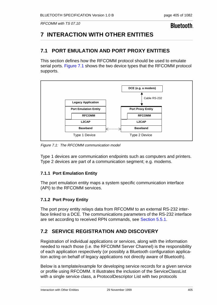
BLUETOOTH SPECIFICATION Version 1.0 B page 405 of 1082
RFCOMM with TS 07.10
7 INTERACTION WITH OTHER ENTITIES
7.1 PORT EMULATION AND PORT PROXY ENTITIES
This section defines how the RFCOMM protocol should be used to emulate serial ports. Figure 7.1 shows the two device types that the RFCOMM protocol supports.
Figure 7.1: The RFCOMM communication model
Type 1 devices are communication endpoints such as computers and printers. Type 2 devices are part of a communication segment; e.g. modems.
7.1.1 Port Emulation Entity
The port emulation entity maps a system specific communication interface (API) to the RFCOMM services.
7.1.2 Port Proxy Entity
The port proxy entity relays data from RFCOMM to an external RS-232 inter-face linked to a DCE. The communications parameters of the RS-232 interface are set according to received RPN commands, see Section 5.5.1.
7.2 SERVICE REGISTRATION AND DISCOVERY
Registration of individual applications or services, along with the information needed to reach those (i.e. the RFCOMM Server Channel) is the responsibility of each application respectively (or possibly a Bluetooth configuration applica-tion acting on behalf of legacy applications not directly aware of Bluetooth).
Below is a template/example for developing service records for a given service or profile using RFCOMM. It illustrates the inclusion of the ServiceClassList with a single service class, a ProtocolDescriptor List with two protocols
Port Emulation Entity
Baseband
L2CAP
RFCOMM
Legacy Application
Port Proxy Entity
Baseband
L2CAP
RFCOMM
DCE (e.g. a modem)
Cable RS-232
Type 1 Device Type 2 Device
Interaction with Other Entities 29 November 1999 405

BLUETOOTH SPECIFICATION Version 1.0 B page 406 of 1082
RFCOMM with TS 07.10
(although there may be more protocols on top of RFCOMM). The example shows the use of one other universal attribute (ServiceName). For each ser-vice running on top of RFCOMM, appropriate SDP-defined universal attributes and/or service-specific attributes will apply. For additional information on Ser-vice Records, see the SDP Specification, Section 2.2 on page 332.
The attributes that a client application needs (at a minimum) to connect to a service on top of RFCOMM are the ServiceClassIDList and the ProtocolDe-scriptorList (corresponding to the shaded rows in the table below).
Notes:
1. Defined in “Bluetooth Assigned Numbers” on page 1009.
2. For national language support for all ’displayable’ text string attributes, an offset has to be added to the LanguageBaseAttributeIDList value for the selected language (see the SDP Specification, Section 5.1.14 on page 365 for details).
3. To be defined (where necessary) for the specific service.
4. For a specific service some of the SDP-defined universal attributes may apply. See the SDP Specification, Section 5.1 on page 358.
5. This indicates the class of service. It can be a single entry or a list of service classes ranging from generic to most specific.
Item Definition Type/Size Value Attribute ID
ServiceClassIDList Note1 0x0001
ServiceClass0 Note5 UUID/32-bit Note1
ProtocolDescriptorList 0x0004
Protocol0 L2CAP UUID/32-bit L2CAP
/Note1
Protocol1 RFCOMM UUID/32-bit RFCOMM
/Note1
ProtocolSpecificParameter0 Server Channel
Uint8 N = server channel #
[other protocols] UUID/32-bit Note1
[other protocol-specific parame-ters]
Note3 Note3 Note3
ServiceName Displayable text name
DataElement/String
’Example service’
Note2
[other universal attributes as appropriate for this service]
Note4 Note4 Note4 Note4
[service-specific attributes] Note3 Note3 Note3 Note3
406 29 November 1999 Interaction with Other Entities
BLUETOOTH SPECIFICATION Version 1.0 B page 407 of 1082
RFCOMM with TS 07.10
7.3 LOWER LAYER DEPENDENCIES
7.3.1 Reliability
RFCOMM uses the services of L2CAP to establish L2CAP channels to RFCOMM entities on other devices. An L2CAP channel is used for the RFCOMM/TS 07.10 multiplexer session. On such a channel, the TS 07.10 frames listed in Section 4.2 are sent, with the adaptation defined in Section 5.1.
Some frame types (SABM and DISC) as well as UIH frames with multiplexer control commands sent on DLCI 0 always require a response from the remote entity, so they are acknowledged on the RFCOMM level (but not retransmitted in the absence of acknowledgment, see Section 5.3). Data frames do not require any response in the RFCOMM protocol, and are thus unacknowledged.
Therefore, RFCOMM must require L2CAP to provide channels with maximum reliability, to ensure that all frames are delivered in order, and without dupli-cates. Should an L2CAP channel fail to provide this, RFCOMM expects a link loss notification, which should be handled by RFCOMM as described in Section 5.2.3.
7.3.2 Low power modes
If all L2CAP channels towards a certain device are idle for a certain amount of time, a decision may be made to put that device in a low power mode (i.e. use hold, sniff or park, see ’Baseband Specification’ Section 10.10.3 on page 125). This will be done without any interference from RFCOMM. RFCOMM can state its latency requirements to L2CAP.This information may be used by lower lay-ers to decide which low power mode(s) to use.
The RFCOMM protocol as such does not suffer from latency delays incurred by low power modes, and consequentially, this specification does not state any maximum latency requirement on RFCOMM’s behalf. Latency sensitivity inher-ently depends on application requirements, which suggests that an RFCOMM service interface implementation could include a way for applications to state latency requirements, to be aggregated and conveyed to L2CAP by the RFCOMM implementation. (That is if such procedures make sense for a partic-ular platform.)
Interaction with Other Entities 29 November 1999 407

BLUETOOTH SPECIFICATION Version 1.0 B page 408 of 1082
RFCOMM with TS 07.10
8 REFERENCES
[1] TS 07.10, ver 6.3.0, ETSI
[2] Bluetooth L2CAP Specification
[3] Bluetooth SDP Specification
[4] Bluetooth Assigned Numbers
408 29 November 1999 References

BLUETOOTH SPECIFICATION Version 1.0 B page 409 of 1082
RFCOMM with TS 07.10
9 TERMS AND ABBREVIATIONS
The following terms are used throughout the document.
DTE Data Terminal Equipment – in serial communications, DTE refers to a device at the endpoint of the communications path; typically a com-puter or terminal
DCE Data Circuit-Terminating Equipment – in serial communications, DCE refers to a device between the communication endpoints whose sole task is to facilitate the communications process; typically a modem
RFCOMM initiator The device initiating the RFCOMM session; i.e.setting up RFCOMM channel on L2CAP and starting RFCOMM multiplexing with the SABM command frame on DLCI 0 (zero)
RFCOMM Client An RFCOMM client is an application that requests a connection to another application (RFCOMM server)
RFCOMM Server An RFCOMM server is an application that awaits a connection from an RFCOMM client on another device. What happens after such a con-nection is established is not within the scope of this definition
RFCOMM Server Channel
This is a subfield of the TS 07.10 DLCI number. This abstraction is used to allow both server and client applications to reside on both sides of an RFCOMM session
Terms and Abbreviations 29 November 1999 409

BLUETOOTH SPECIFICATION Version 1.0 B page 410 of 1082
RFCOMM with TS 07.10
410 29 November 1999 Terms and Abbreviations

Part F:2
IrDA INTEROPERABILITY
The IrOBEX protocol is utilized by the Bluetooth technology. In Bluetooth, OBEX offers the same features for applications as within the IrDA protocol hierarchy, enabling the applications to work over the Bluetooth protocol stack as well as the IrDA stack.

BLUETOOTH SPECIFICATION Version 1.0 B page 412 of 1082
IrDA Interoperability
412 29 November 1999

BLUETOOTH SPECIFICATION Version 1.0 B page 413 of 1082
IrDA Interoperability
CONTENTS
1 Introduction ......................................................................................4141.1 OBEX and Bluetooth Architecture............................................4151.2 Bluetooth OBEX-Related Specifications ..................................4151.3 Other IrOBEX Implementations................................................416
2 OBEX Object and Protocol ..............................................................4172.1 Object.......................................................................................4172.2 Session Protocol ......................................................................417
2.2.1 Connect Operation ......................................................418
2.2.2 Disconnect Operation..................................................419
2.2.3 Put Operation ..............................................................419
2.2.4 Get Operation..............................................................420
2.2.5 Other Operations.........................................................420
3 OBEX over RFCOMM .......................................................................4213.1 OBEX Server Start-up on RFCOMM........................................4213.2 Receiving OBEX Packets from Serial Port...............................4213.3 Connection Establishment .......................................................4223.4 Disconnection ..........................................................................4223.5 Pushing and Pulling OBEX Packets over RFCOMM ...............422
4 OBEX over TCP/IP............................................................................4234.1 OBEX Server Start-up on TCP/IP ............................................4234.2 Connection Establishment .......................................................4234.3 Disconnection ..........................................................................4244.4 Pushing and Pulling OBEX Packets over TCP ........................424
5 Bluetooth Application Profiles using OBEX..................................4255.1 Synchronization .......................................................................4255.2 File Transfer .............................................................................4255.3 Object Push .............................................................................426
6 References........................................................................................427
7 List of Acronyms and Abbreviations..............................................428
29 November 1999 413

BLUETOOTH SPECIFICATION Version 1.0 B page 414 of 1082
IrDA Interoperability
1 INTRODUCTION
The goal of this document is to enable the development of application pro-grams that function well over both short-range RF and IR media. Each media type has its advantages and disadvantages but the goal is for applications to work over both. Rather than fragment the application domain, this document defines the intersection point where Bluetooth and IrDA applications may con-verge. That intersection point is IrOBEX [1].
IrOBEX is a session protocol defined by IrDA. This protocol is now also utilized by the Bluetooth technology, making it possible for applications to use either the Bluetooth radio technology or the IrDA IR technology. However, even though both IrDA and Bluetooth are designed for short-range wireless commu-nications, they have some fundamental differences relating to the lower-layer protocols. IrOBEX will therefore be mapped over the lower layer protocols which are adopted by Bluetooth.
This document defines how IrOBEX (OBEX for short) is mapped over RFCOMM [2] and TCP/IP [3]. Originally, OBEX (Object Exchange Protocol) was developed to exchange data objects over an infrared link and was placed within the IrDA protocol hierarchy. However, it can appear above other trans-port layers, now RFCOMM and TCP/IP. At this moment, it is worth mentioning that the OBEX over TCP/IP implementation is an optional feature for Bluetooth devices supporting the OBEX protocol.
The IrOBEX specification [1] provides a model for representing objects and a session protocol, which structures the dialogue between two devices. The IrOBEX protocol follows a client/server request-response paradigm for the conversation format.
Bluetooth uses only the connection-oriented OBEX even though IrDA has specified the connectionless OBEX also. The reasons for the connection-oriented approach are:
• OBEX is mapped over the connection-oriented protocols in the Bluetooth architecture.
• Most of application profiles using OBEX and Bluetooth needs a connection-oriented OBEX to provide the functionality described for the features included in these profiles.
• The connectionless OBEX with the connection-oriented one would raise the interoperability problems, which are not desirable.
414 29 November 1999 Introduction
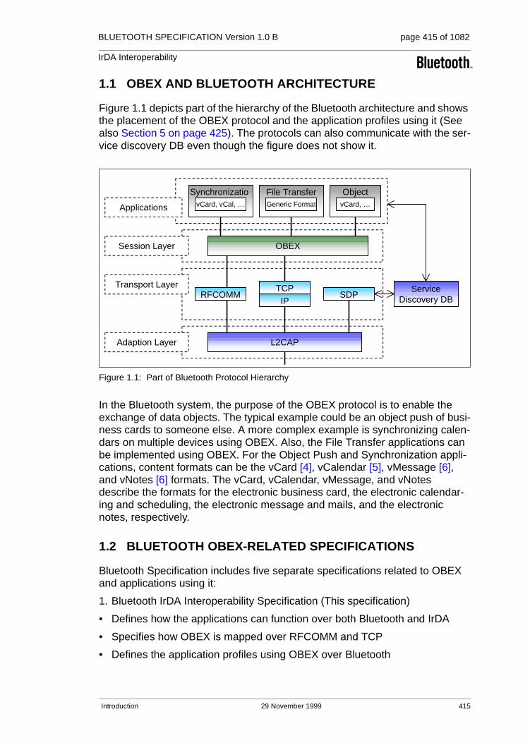
BLUETOOTH SPECIFICATION Version 1.0 B page 415 of 1082
IrDA Interoperability
1.1 OBEX AND BLUETOOTH ARCHITECTURE
Figure 1.1 depicts part of the hierarchy of the Bluetooth architecture and shows the placement of the OBEX protocol and the application profiles using it (See also Section 5 on page 425). The protocols can also communicate with the ser-vice discovery DB even though the figure does not show it.
Figure 1.1: Part of Bluetooth Protocol Hierarchy
In the Bluetooth system, the purpose of the OBEX protocol is to enable the exchange of data objects. The typical example could be an object push of busi-ness cards to someone else. A more complex example is synchronizing calen-dars on multiple devices using OBEX. Also, the File Transfer applications can be implemented using OBEX. For the Object Push and Synchronization appli-cations, content formats can be the vCard [4], vCalendar [5], vMessage [6], and vNotes [6] formats. The vCard, vCalendar, vMessage, and vNotes describe the formats for the electronic business card, the electronic calendar-ing and scheduling, the electronic message and mails, and the electronic notes, respectively.
1.2 BLUETOOTH OBEX-RELATED SPECIFICATIONS
Bluetooth Specification includes five separate specifications related to OBEX and applications using it:
1. Bluetooth IrDA Interoperability Specification (This specification)
• Defines how the applications can function over both Bluetooth and IrDA
• Specifies how OBEX is mapped over RFCOMM and TCP
• Defines the application profiles using OBEX over Bluetooth
OBEX
RFCOMM
Synchronization
L2CAP
TCPIP
Applications
Session Layer
Transport Layer
Adaption Layer
ServiceDiscovery DBSDP
vCard, vCal, …
File TransferGeneric Format
ObjectPushvCard, …
Introduction 29 November 1999 415

BLUETOOTH SPECIFICATION Version 1.0 B page 416 of 1082
IrDA Interoperability
2. Bluetooth Generic Object Exchange Profile Specification [7]
• Generic interoperability specification for the application profiles using OBEX
• Defines the interoperability requirements of the lower protocol layers (e.g. Baseband and LMP) for the application profiles
3. Bluetooth Synchronization Profile Specification [8]
• Application Profile for the Synchronization applications
• Defines the interoperability requirements for the applications within the Syn-chronization application profile
• Does not define the requirements for the Baseband, LMP, L2CAP, or RFCOMM.
4. Bluetooth File Transfer Profile Specification [9]
• Application Profile for the File Transfer applications
• Defines the interoperability requirements for the applications within the File Transfer application profile.
• Does not define the requirements for the Baseband, LMP, L2CAP, or RFCOMM.
5. Bluetooth Object Push Profile Specification [10]
• Application Profile for the Object Push applications
• Defines the interoperability requirements for the applications within the Object Push application profile.
• Does not define the requirements for the Baseband, LMP, L2CAP, or RFCOMM.
1.3 OTHER IROBEX IMPLEMENTATIONS
Over IR, OBEX has also been implemented over IrCOMM and Tiny TP. The Bluetooth technology does not define these protocols as transport protocols for OBEX, but they can be supported by independent software vendors if desired.
416 29 November 1999 Introduction

BLUETOOTH SPECIFICATION Version 1.0 B page 417 of 1082
IrDA Interoperability
2 OBEX OBJECT AND PROTOCOL
This section is dedicated to the model of OBEX objects and the OBEX session protocol. The section is intended to be read with the IrOBEX specification [1].
2.1 OBJECT
The OBEX object model (Section 2 in [1]) describes how OBEX objects are presented. The OBEX protocol can transfer an object by using the Put- and Get-operations (See Section 2.2.3 and 2.2.4). One object can be exchanged in one or more Put-requests or Get-responses.
The model handles both information about the object (e.g. type) and object itself. It is composed of headers, which consist of a header ID and value (See Section 2.1 in [1]). The header ID describes what the header contains and how it is formatted, and the header value consists of one or more bytes in the format and meaning specified by Header ID. The specified headers are Count, Name, Type, Length, Time, Description, Target, HTTP, Body, End of Body, Who, Connection ID, Application Parameters, Authenticate Challenge, Authen-ticate Response, Object Class, and User-Defined Headers. These are explained in detail by Section 2.2 in the IrOBEX specification.
2.2 SESSION PROTOCOL
The OBEX operations are formed by response-request pairs. Requests are issued by the client and responses by the server. After sending a request, the client waits for a response from the server before issuing a new request. Each request packet consists of a one-byte opcode (See Section 3.3 in [1]), a two-byte length indicator, and required or optional data depending on the operation. Each response packet consists of a one-byte response code (See Section 3.2.1 in [1]), a two-byte length indicator, and required or optional data depend-ing on the operation.
In the following subsections, the OBEX operations are explained in general.
OBEX Object and Protocol 29 November 1999 417

BLUETOOTH SPECIFICATION Version 1.0 B page 418 of 1082
IrDA Interoperability
2.2.1 Connect Operation
An OBEX session is started, when an application asks the first time to transmit an OBEX object. An OBEX client starts the establishment of an OBEX connec-tion. The session is started by sending a Connect-request (See Section 3.3.1 in [1]). The request format is:
Note. The Big Endian format is used to define the byte ordering for the PDUs (requests and responses) in this specification as well as in the IrOBEX specifi-cation; i.e. the most significant byte (MSB) is always on left and the least significant byte (LSB) on right.
At the remote host, the Connect-request is received by the OBEX server, if it exists. The server accepts the connection by sending the successful response to the client. Sending any other response (i.e. a non-successful response) back to the client indicates a failure to make a connection. The response format is:
The response codes are list in the Section 3.2.1 in the IrOBEX specification. The bytes 5 and 6 define the maximum OBEX packet length, which can be received by the server. This value may differ from the length, which can be received by the client. These Connect-request and response packets must each fit in a single packet.
Once a connection is established it remains ‘alive’, and is only disconnected by requests/responses or by failures (i.e. the connection is not automatically dis-connected after each OBEX object has completely transmitted).
Byte 0 Bytes 1 and 2 Byte 3 Byte 4 Bytes 5 and 6 Byte 7 to n
0x80(opcode)
Connect request packet length
OBEX version number
Flags Maximum OBEX packet length
Optional headers
Byte 0 Bytes 1 and 2 Byte 3 Byte 4 Bytes 5 and 6 Byte 7 to n
Responsecode
Connect response packet length
OBEX version number
Flags Maximum OBEX packet length
Optional headers
418 29 November 1999 OBEX Object and Protocol

BLUETOOTH SPECIFICATION Version 1.0 B page 419 of 1082
IrDA Interoperability
2.2.2 Disconnect Operation
The disconnection of an OBEX session occurs when an application, which is needed for an OBEX connection, is closed or the application wants to change the host to which the requests are issued. The client issues the Disconnect-request (See Section 3.3.2 in [1]) to the server. The request format is:
The request cannot be refused by the server. Thus, it has to send the response, and the response format is:
2.2.3 Put Operation
When the connection has been established between the client and server the client is able to push OBEX objects to the server. The Put-request is used to push an OBEX object (See Section 3.3.3 in [1]). The request has the following format.
A Put-request consists of one or more request packets, depending on how large the transferred object is, and how large the packet size is. A response packet from the server is required for every Put-request packet. Thus, one response is not permitted for several request packets, although they consist of one OBEX object. The response format is:
Byte 0 Bytes 1 and 2 Byte 3
0x81 Packet length Optional headers
Byte 0 Bytes 1 and 2 Byte 3
0xA0 Response packet length
Optional response headers
Byte 0 Bytes 1 and 2 Byte 3
0x02 (0x82 when Final bit set)
Packet length Sequence of headers
Byte 0 Bytes 1 and 2 Byte 3
Response code Response packet length
Optional response headers
OBEX Object and Protocol 29 November 1999 419
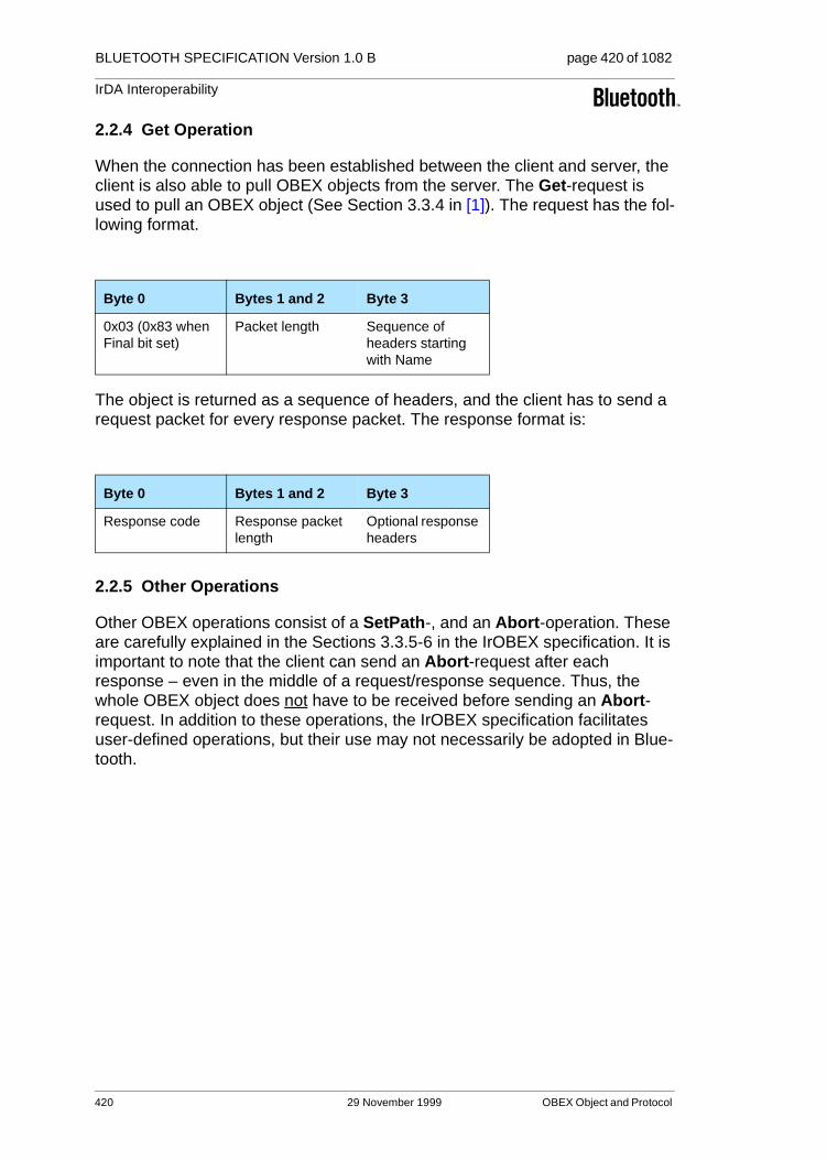
BLUETOOTH SPECIFICATION Version 1.0 B page 420 of 1082
IrDA Interoperability
2.2.4 Get Operation
When the connection has been established between the client and server, the client is also able to pull OBEX objects from the server. The Get-request is used to pull an OBEX object (See Section 3.3.4 in [1]). The request has the fol-lowing format.
The object is returned as a sequence of headers, and the client has to send a request packet for every response packet. The response format is:
2.2.5 Other Operations
Other OBEX operations consist of a SetPath-, and an Abort-operation. These are carefully explained in the Sections 3.3.5-6 in the IrOBEX specification. It is important to note that the client can send an Abort-request after each response – even in the middle of a request/response sequence. Thus, the whole OBEX object does not have to be received before sending an Abort-request. In addition to these operations, the IrOBEX specification facilitates user-defined operations, but their use may not necessarily be adopted in Blue-tooth.
Byte 0 Bytes 1 and 2 Byte 3
0x03 (0x83 when Final bit set)
Packet length Sequence of headers starting with Name
Byte 0 Bytes 1 and 2 Byte 3
Response code Response packet length
Optional response headers
420 29 November 1999 OBEX Object and Protocol

BLUETOOTH SPECIFICATION Version 1.0 B page 421 of 1082
IrDA Interoperability
3 OBEX OVER RFCOMM
This section specifies how OBEX is mapped over RFCOMM, which is the mul-tiplexing and transport protocol based on ETSI TS 07.10 [11] and which also provides a support for serial cable emulation. The Bluetooth devices supporting the OBEX protocol must satisfy the following requirements.
1. The device supporting OBEX must be able to function as either a client, a server, or both
2. All servers running simultaneously on a device must use separate RFCOMM server channels
3. Applications (service/server) using OBEX must be able to register the proper information into the service discovery database. This information for different application profiles is specified in the profile specifications
3.1 OBEX SERVER START-UP ON RFCOMM
When a client sends a connecting request, a server is assumed to be ready to receive requests. However, before the server is ready to receive (i.e. is run-ning) certain prerequisites must be fulfilled before the server can enter the lis-tening mode:
1. The server must open an RFCOMM server channel
2. The server must register its capabilities into the service discovery database
After this, other hosts are able to find the server if needed, and the server listens for get requests from clients.
3.2 RECEIVING OBEX PACKETS FROM SERIAL PORT
As discussed earlier, one object can be exchanged over one or more Put-requests or Get-responses (i.e. the object is received in one or several pack-ets). However, if OBEX is running directly over the serial port, it does not receive packets from RFCOMM. Instead, a byte stream is received by OBEX from a serial port emulated by RFCOMM.
To detect packets in the byte stream, OBEX has to look for opcodes or response codes (See Chapter 2.2) depending on whether a packet is a request or a response. The opcodes and response code can be thought of as the start flags of packets. In OBEX packets, there is no ‘end flag’ that would indicate the end of a packet. However, after the opcode or response code, the length of a packet is received in the next two bytes. Thus, the whole length of a packet is known, and the boundary of two packets can be determined.
OBEX over RFCOMM 29 November 1999 421
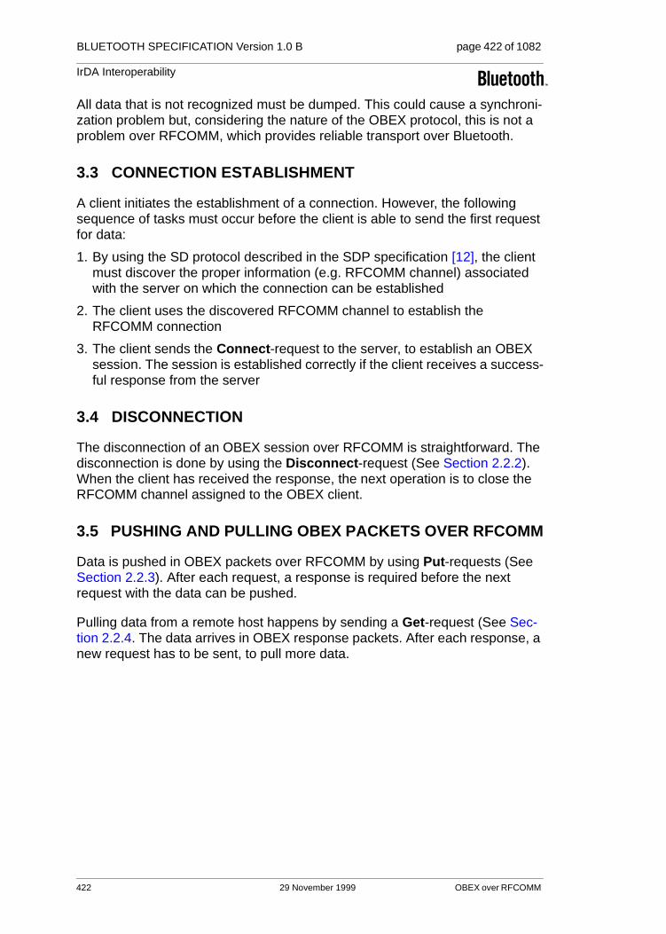
BLUETOOTH SPECIFICATION Version 1.0 B page 422 of 1082
IrDA Interoperability
All data that is not recognized must be dumped. This could cause a synchroni-zation problem but, considering the nature of the OBEX protocol, this is not a problem over RFCOMM, which provides reliable transport over Bluetooth.
3.3 CONNECTION ESTABLISHMENT
A client initiates the establishment of a connection. However, the following sequence of tasks must occur before the client is able to send the first request for data:
1. By using the SD protocol described in the SDP specification [12], the client must discover the proper information (e.g. RFCOMM channel) associated with the server on which the connection can be established
2. The client uses the discovered RFCOMM channel to establish the RFCOMM connection
3. The client sends the Connect-request to the server, to establish an OBEX session. The session is established correctly if the client receives a success-ful response from the server
3.4 DISCONNECTION
The disconnection of an OBEX session over RFCOMM is straightforward. The disconnection is done by using the Disconnect-request (See Section 2.2.2). When the client has received the response, the next operation is to close the RFCOMM channel assigned to the OBEX client.
3.5 PUSHING AND PULLING OBEX PACKETS OVER RFCOMM
Data is pushed in OBEX packets over RFCOMM by using Put-requests (See Section 2.2.3). After each request, a response is required before the next request with the data can be pushed.
Pulling data from a remote host happens by sending a Get-request (See Sec-tion 2.2.4. The data arrives in OBEX response packets. After each response, a new request has to be sent, to pull more data.
422 29 November 1999 OBEX over RFCOMM

BLUETOOTH SPECIFICATION Version 1.0 B page 423 of 1082
IrDA Interoperability
4 OBEX OVER TCP/IP
This section specifies how OBEX is mapped over the TCP/IP creating reliable connection-oriented services for OBEX. This specification does not define how TCP/IP is mapped over Bluetooth.
The Bluetooth devices, which support the OBEX protocol over TCP/IP, must satisfy the following requirements:
1. The device supporting OBEX must be able to function as either a client, or a server, or both
2. For the server, the TCP port number 650 is assigned by IANA. If an assigned number is not desirable, the port number can be a value above 1023. However, the use of the TCP port number (650) defined by IANA is highly recommended. The 0-1023 range is reserved by IANA (See [13])
3. The client must use a port number (on the client side), which is not within the 0-1023 range
4. Applications (service/server) using OBEX must be able to register the proper information into the service discovery database. This information for different application profiles is specified in the profile specifications
4.1 OBEX SERVER START-UP ON TCP/IP
When a client sends a Put- or Get-request, a server is assumed to be ready to receive requests. However, when the server is ready (i.e. is running), certain prerequisites must be fulfilled before the server can enter the listening mode:
1. The server must initialize a TCP port with the value 650 or value above 1023
2. The server registers its capabilities into the service discovery database
After this, other devices are able to find the server if needed, and the server listens for get requests from clients.
4.2 CONNECTION ESTABLISHMENT
A client initiates a connection. However, the following sequence of tasks must occur before a connection can be established:
1. By using, the SD protocol described in the SDP specification [12], the client discovers the proper information (e.g. TCP port number) associated with the server, to enable the connection can be established
2. The client initializes a socket associated to a TCP port number above 1023, and establishes a TCP connection with the host of the server
3. The client sends the Connect-request to the server, to establish an OBEX session. The session is established correctly if the client receives a success-ful response from the server.
OBEX over TCP/IP 29 November 1999 423
BLUETOOTH SPECIFICATION Version 1.0 B page 424 of 1082
IrDA Interoperability
4.3 DISCONNECTION
The disconnection of an OBEX session over TCP is straightforward. The dis-connection is done by using the Disconnect-request (See Section 2.2.2). When the client has received the response, the next operation is to close the TCP port dedicated for this session.
4.4 PUSHING AND PULLING OBEX PACKETS OVER TCP
See Section 3.5.
424 29 November 1999 OBEX over TCP/IP

BLUETOOTH SPECIFICATION Version 1.0 B page 425 of 1082
IrDA Interoperability
5 BLUETOOTH APPLICATION PROFILES USING OBEX
Bluetooth SIG (Special Interest Group) has defined three separate application profiles using OBEX. These profiles are briefly introduced in this section.
5.1 SYNCHRONIZATION
Basically, the synchronization means comparing two object stores, determining their inequalities, and then unifying these two object stores. The Bluetooth devices supporting the synchronization may be desktop PCs, notebooks, PDAs, cellular phones, or smart phones.
The Bluetooth Synchronization profile uses the servers and clients compliant to the IrMC synchronization specified by IrDA (See Section 5 in [6]). The Bluetooth Synchronization servers and clients must support the level 4 synchronization functionality specified in the IrMC specification.
The actual logic of the synchronization engines which process the synchroniza-tion algorithm at the client device is implementation-specific. It is therefore left to the participating software vendors, and is not considered in the Bluetooth specifications.
The synchronization is not limited to one type of application. The Bluetooth synchronization (i.e. the IrMC synchronization) enables four different applica-tion classes:
1. Phone Book – provides a means for a user to manage contact records
2. Calendar – enables a user to manage calendar items, and can also be used for ‘to-do’ or task lists
3. Messaging – lets a user manage messages (e.g. e-mails)
4. Notes – provides a means for a user to manage small notes
The interoperability requirements for the Bluetooth Synchronization profile are defined in the Synchronization Profile [8] and Generic Object Exchange Profile [7] specifications.
5.2 FILE TRANSFER
At the minimum, the File Transfer profile is intended for sending and retrieving generic files to and from the Bluetooth device. The File Transfer service also facilitates the browsing of the remote Bluetooth device’s folder.
The interoperability requirements for the Bluetooth File Transfer profile are defined in the File Transfer Profile [9] and Generic Object Exchange Profile [7] specifications.
Bluetooth Application Profiles using OBEX 29 November 1999 425

BLUETOOTH SPECIFICATION Version 1.0 B page 426 of 1082
IrDA Interoperability
5.3 OBJECT PUSH
The Object Push profile is the special case of the File Transfer Profile for beaming objects and optionally pulling the default objects. At a minimum, it offers the capability to exchange business cards, but is not limited to this ser-vice.
The interoperability requirements for the Object Push profile are defined in the Object Push Profile [10] and Generic Object Exchange Profile [7] specifica-tions.
426 29 November 1999 Bluetooth Application Profiles using OBEX

BLUETOOTH SPECIFICATION Version 1.0 B page 427 of 1082
IrDA Interoperability
6 REFERENCES
[1] Infrared Data Association, IrDA Object Exchange Protocol (IrOBEX), Version 1.2, April 1999
[2] Bluetooth RFCOMM with TS 07.10, on page 385
[3] Internet Engineering Task Force, IETF Directory List of RFCs (http://www.ietf.org/rfc/), May 1999.
[4] The Internet Mail Consortium, vCard - The Electronic Business Card Exchange Format, Version 2.1, September 1996.
[5] The Internet Mail Consortium, vCalendar - The Electronic Calendaring and Scheduling Exchange Format, Version 1.0, September 1996.
[6] Infrared Data Association, IrMC (Ir Mobile Communications) Specifica-tion, Version 1.1, February 1999.
[7] Bluetooth Generic Object Exchange Profile, see Volume 2.
[8] Bluetooth Synchronization Profile, see Volume 2.
[9] Bluetooth File Transfer Profile, see Volume 2.
[10] Bluetooth Object Push Profile, see Volume 2.
[11] ETSI, TS 07.10, Version 6.3.0
[12] Bluetooth Service Discovery Protocol, see Volume 2.
[13] Internet Assigned Numbers Authority, IANA Protocol/Number Assign-ments Directory (http://www.iana.org/numbers.html), May 1999.
References 29 November 1999 427

BLUETOOTH SPECIFICATION Version 1.0 B page 428 of 1082
IrDA Interoperability
7 LIST OF ACRONYMS AND ABBREVIATIONS
Abbreviation or Acronym Meaning
GEOP Generic Object Exchange Profile
IrDA Infrared Data Association
IrMC Ir Mobile Communications
L2CAP Logical Link Control and Adaptation Protocol
LSB Least Significant Byte
MSB Most Significant Byte
OBEX Object exchange protocol
PDU Protocol Data Unit
RFCOMM Serial cable emulation protocol based on ETSI TS 07.10
SD Service Discovery
SDP Service Discovery Protocol
SDDB Service Discovery Database
TCP/IP Transport Control Protocol/Internet Protocol
428 29 November 1999 List of Acronyms and Abbreviations
Part F:3
TELEPHONY CONTROL PROTOCOL SPECIFICATION
TCS Binary
This document describes the Bluetooth Telephony Control protocol Specification − Binary (TCS Binary), using a bit-oriented protocol. This protocol defines the call control signalling for the establishment of speech and data calls between Bluetooth devices. In addition, it defines mobility management procedures for handling Bluetooth TCS devices.

BLUETOOTH SPECIFICATION Version 1.0 B page 430 of 1082
Telephony Control Protocol Specification
430 29 November 1999
BLUETOOTH SPECIFICATION Version 1.0 B page 431 of 1082
Telephony Control Protocol Specification
CONTENTS
1 General Description .........................................................................4351.1 Overview ..................................................................................4351.2 Operation between devices......................................................4351.3 Operation between layers ........................................................437
2 Call Control (CC) ..............................................................................4392.1 Call States................................................................................4392.2 Call Establishment ...................................................................439
2.2.1 Call Request................................................................439
2.2.2 Bearer selection ..........................................................440
2.2.3 Overlap Sending..........................................................441
2.2.4 Call Proceeding...........................................................441
2.2.4.1 Call proceeding, enbloc sending...................4412.2.4.2 Call proceeding, overlap sending..................4422.2.4.3 Expiry of timer T310......................................442
2.2.5 Call Confirmation.........................................................442
2.2.6 Call Connection ...........................................................442
2.2.7 Call Information ...........................................................443
2.2.8 Non-selected user clearing..........................................443
2.2.9 In-band tones and announcements.............................443
2.2.10 Failure of call establishment........................................444
2.2.11 Call Establishment Message Flow ..............................445
2.3 Call Clearing.............................................................................4462.3.1 Normal Call Clearing ...................................................446
2.3.2 Abnormal Call Clearing ...............................................447
2.3.3 Clear Collision .............................................................447
2.3.4 Call Clearing Message Flow........................................448
29 November 1999 431

BLUETOOTH SPECIFICATION Version 1.0 B page 432 of 1082
Telephony Control Protocol Specification
3 Group Management (GM) ................................................................4493.1 Overview..................................................................................4493.2 The Wireless User Group ........................................................449
3.2.1 Description ..................................................................449
3.2.2 Encryption within the WUG .........................................450
3.2.3 Unconscious pairing....................................................450
3.3 Obtain Access Rights...............................................................4513.3.1 Procedure description .................................................451
3.3.2 Message flow ..............................................................451
3.4 Configuration Distribution ........................................................4523.4.1 Procedure Description.................................................452
3.4.2 Message flow ..............................................................452
3.5 Fast inter-member Access.......................................................4533.5.1 Listen Request ............................................................453
3.5.2 Listen Accept ..............................................................453
3.5.3 Listen Reject by the WUG Master...............................454
3.5.4 Listen Reject by the WUG Member.............................454
3.5.5 Message flow ..............................................................454
4 Connectionless TCS (CL)................................................................455
5 Supplementary Services (SS) .........................................................4565.1 Calling Line Identity .................................................................4565.2 DTMF start & stop....................................................................456
5.2.1 Start DTMF request.....................................................457
5.2.2 Start DTMF response..................................................457
5.2.3 Stop DTMF request.....................................................457
5.2.4 Stop DTMF response ..................................................457
5.2.5 Message flow ..............................................................457
5.3 Register Recall ........................................................................458
432 29 November 1999

BLUETOOTH SPECIFICATION Version 1.0 B page 433 of 1082
Telephony Control Protocol Specification
6 Message formats ..............................................................................4596.1 Call Control Message Formats.................................................460
6.1.1 ALERTING ..................................................................460
6.1.2 CALL PROCEEDING ..................................................460
6.1.3 CONNECT...................................................................461
6.1.4 CONNECT ACKNOWLEDGE .....................................461
6.1.5 DISCONNECT.............................................................462
6.1.6 INFORMATION ...........................................................462
6.1.7 PROGRESS................................................................463
6.1.8 RELEASE....................................................................463
6.1.9 RELEASE COMPLETE...............................................464
6.1.10 SETUP ........................................................................464
6.1.11 SETUP ACKNOWLEDGE...........................................465
6.1.12 Start DTMF..................................................................465
6.1.13 Start DTMF Acknowledge............................................466
6.1.14 Start DTMF Reject.......................................................466
6.1.15 Stop DTMF ..................................................................466
6.1.16 Stop DTMF Acknowledge............................................467
6.2 Group Management Message Formats ...................................4676.2.1 ACCESS RIGHTS REQUEST.....................................467
6.2.2 ACCESS RIGHTS ACCEPT .......................................467
6.2.3 ACCESS RIGHTS REJECT........................................468
6.2.4 INFO SUGGEST .........................................................468
6.2.5 INFO ACCEPT ............................................................468
6.2.6 LISTEN REQUEST .....................................................469
6.2.7 LISTEN SUGGEST .....................................................469
6.2.8 LISTEN ACCEPT ........................................................469
6.2.9 LISTEN REJECT.........................................................470
6.3 TCS Connectionless Message Formats...................................4706.3.1 CL INFO ......................................................................470
7 Message coding ...............................................................................4717.1 Overview ..................................................................................4717.2 Protocol Discriminator ..............................................................4727.3 Message Type..........................................................................4727.4 Other Information Elements .....................................................474
7.4.1 Coding rules ................................................................474
7.4.2 Audio control ...............................................................476
7.4.3 Bearer capability..........................................................476
7.4.4 Call class .....................................................................479
29 November 1999 433

BLUETOOTH SPECIFICATION Version 1.0 B page 434 of 1082
Telephony Control Protocol Specification
7.4.5 Called party number....................................................480
7.4.6 Calling party number ...................................................481
7.4.7 Cause..........................................................................482
7.4.8 Clock offset .................................................................482
7.4.9 Company specific........................................................483
7.4.10 Configuration data.......................................................484
7.4.11 Destination CID...........................................................485
7.4.12 Keypad facility .............................................................485
7.4.13 Progress indicator .......................................................485
7.4.14 SCO Handle................................................................486
7.4.15 Sending complete .......................................................486
7.4.16 Signal ..........................................................................486
8 Message Error handling ..................................................................4878.1 Protocol Discrimination Error ...................................................4878.2 Message Too Short or Unrecognized ......................................4878.3 Message Type or Message Sequence Errors..........................4878.4 Information Element Errors......................................................487
9 Protocol Parameters........................................................................4899.1 Protocol Timers .......................................................................489
10 References........................................................................................490
11 List of Figures ..................................................................................491
12 List of Tables ....................................................................................492
Appendix 1 - TCS Call States ....................................................................493
434 29 November 1999

BLUETOOTH SPECIFICATION Version 1.0 B page 435 of 1082
Telephony Control Protocol Specification
1 GENERAL DESCRIPTION
1.1 OVERVIEW
The Bluetooth Telephony Control protocol Specification Binary (TCS Binary) is based on the ITU-T Recommendation Q.931[1], applying the symmetrical pro-visions as stated in Annex D of Q.931. The resulting text does not discriminate between user and network side, but merely between Outgoing Side (the party originating the call) and Incoming Side (the party terminating the call). Effort was made to only apply those changes necessary for Bluetooth and foreseen applications, enabling re-use of Q.931 to the largest extent possible.
Figure 1.1: TCS within the Bluetooth stack
The TCS contains the following functionality:
• Call Control (CC) – signalling for the establishment and release of speech and data calls between Bluetooth devices
• Group Management – signalling to ease the handling of groups of Bluetooth devices
• ConnectionLess TCS (CL) – provisions to exchange signalling information not related to an ongoing call
1.2 OPERATION BETWEEN DEVICES
TCS uses point-to-point signalling and may use point-to-multipoint signalling. Point-to-point signalling is used when it is known to which side (Bluetooth device) a call needs to be established (single-point configuration).
Point-to-multipoint signalling may be used when there are more sides available for call establishment (multi-point configuration); e.g. when, for an incoming call, a home base station needs to alert all phones in range.
Outgoing Side
Physical
Data Link
Baseband Baseband
CC GM CLTelephony Control
CC GM CL
L2CAPLMP L2CAPLMP
Incoming Side
General Description 29 November 1999 435

BLUETOOTH SPECIFICATION Version 1.0 B page 436 of 1082
Telephony Control Protocol Specification
Point-to-point signalling is mapped towards a connection-oriented L2CAP channel, whereas point-to-multipoint signalling is mapped towards the connec-tionless L2CAP channel, which in turn is sent as broadcast information on the beacon channel (piconet broadcast).
Figure 1.2 illustrates point-to-point signalling to establish a voice or data call in a single-point configuration. First the other device is notified of the call request using the point-to-point signalling channel (A). Next, this signalling channel is used to further establish the speech or data channel (B).
Figure 1.2: Point-to-point signalling in a single-point configuration
Figure 1.3 below illustrates how point-to-multipoint signalling and point-to-point signalling is used to establish a voice or data call in a multi-point configuration. First all devices are notified of the call request using point-to-multipoint signal-ling channel (A). Next, one of the devices answers the call on the point-to-point signalling channel (B); this signalling channel is used to further establish the speech or data channel (C).
Figure 1.3: Signalling in a multi-point configuration
Device #1
TCS
Device #2
TCS
Point-to-pointsignalling channel
Speech or datachannel
A
B
Device #1
TCS
Device #2
TCS
Point-to-pointsignalling channel
Speech or datachannel
Device #3
TCS
Device #4
TCS
Point-to-multipointsignalling channel
A
AA
B C
436 29 November 1999 General Description

BLUETOOTH SPECIFICATION Version 1.0 B page 437 of 1082
Telephony Control Protocol Specification
1.3 OPERATION BETWEEN LAYERS
TCS implementations should follow the general architecture described below (note that, for simplicity, handling of data calls is not drawn).
Figure 1.4: TCS Architecture
The internal structure of TCS Binary contains the functional entities Call Con-trol, Group Management and ConnectionLess as described in Section 1.1 on page 435, complemented with the Protocol Discrimination which, based upon the TCS internal protocol discriminator, routes traffic to the appropriate func-tional entity.
CL GM CC
ProtocolDiscrimination
Telephony Application
ACL SCO
Spe
ech
TCS Binary
LMP
L2CAP
BaseBand
CO CL
SpeechSynchronisation
ControlSDP
F E D
C B
A
G
General Description 29 November 1999 437

BLUETOOTH SPECIFICATION Version 1.0 B page 438 of 1082
Telephony Control Protocol Specification
To handle more calls simultaneously, multiple instances of TCS Binary may exist at the same time. Discrimination between the multiple instances can be based on the L2CAP channel identifier.
TCS Binary interfaces with a number of other (Bluetooth) entities to provide its (telephone) services to the application. The interfaces are identified in Figure 1.4 above, and information is exchanged across these interfaces for the follow-ing purposes:
A The Call Control entity provides information to the speech synchronization control about when to connect (disconnect) the speech paths. This informa-tion is based upon the call control messages (e.g. reception of CONNECT ACKNOWLEDGE or DISCONNECT, see Section 2 on page 439)
B To send a SETUP message (see Section 2.2.1 on page 439) using point-to-multipoint signalling, it is delivered on this interface to L2CAP for transmis-sion on the connectionless channel. The other way round – L2CAP uses this interface to inform TCS of a SETUP message received on the connection-less channel. The connectionless L2CAP channel maps onto the piconet broadcast
C Whenever a TCS message needs to be sent using point-to-point signalling, it is delivered on this interface to L2CAP for transmission on a connection-oriented channel. During L2CAP channel establishment specific quality of service to be used for the connection will be indicated, in particular the usage of low power modes (L2CAP will inform LMP about this – interface F)
D The Call Control entity controls the LMP directly, for the purpose of estab-lishing and releasing SCO links
E & G. The Group Management entity controls the LMP and LC/Baseband directly during initialization procedures to control (for example) the inquiry, paging and pairing.
438 29 November 1999 General Description

BLUETOOTH SPECIFICATION Version 1.0 B page 439 of 1082
Telephony Control Protocol Specification
2 CALL CONTROL (CC)
2.1 CALL STATES
The call states used by the TCS are those identified in Q.931[1], for the user side only. To allow for implementation within computing power- and memory- restricted devices, only a subset of the states is mandatory for TCS based implementations. This mandatory subset is termed Lean TCS.
The states are named as follows. States in bold are mandatory states, part of Lean TCS:
General StatesNull (0)Active (10)Disconnect request (11)Disconnect indication (12)Release request (19)
Outgoing Side StatesCall initiated (1)Overlap sending (2)Outgoing call proceeding (3)Call delivered (4)
Incoming Side StatesCall present (6)Call received (7)Connect request (8)Incoming call proceeding (9)Overlap receiving (25)
These states, together with the state transitions, have been indicated in the state diagram contained in Appendix 1 – TCS Call States. For clarity, a sepa-rate state diagram has been included for Lean TCS.
2.2 CALL ESTABLISHMENT
A connection-oriented L2CAP channel between the Outgoing and Incoming Side shall be available before any of the CC procedures can operate.
Additionally, in a multi-point configuration (see Section 1.2 on page 435), a connectionless L2CAP channel shall be available between the Outgoing and Incoming Side.
2.2.1 Call Request
The Outgoing Side initiates call establishment by sending a SETUP message, and starting timer T303.
Call Control (CC) 29 November 1999 439

BLUETOOTH SPECIFICATION Version 1.0 B page 440 of 1082
Telephony Control Protocol Specification
In case of a single-point configuration (see Section 1.2 on page 435), the SETUP message is delivered on the connection-oriented channel.
In case of a multi-point configuration (see Section 1.2 on page 435), the SETUP message may be delivered on the connection-less channel. This causes the SETUP message to be transmitted as a broadcast message at every beacon instant (as described in Baseband Specification Section 10.8.4 on page 115).
If no response (as prescribed in Section 2.2.4 on page 441) is received from the Incoming Side before timer T303 expires, the Outgoing Side shall:
1. If the SETUP message was delivered on a connection-less channel, return to the Null state. This stops the transmission of the SETUP message.
2. If the SETUP message was delivered on a connection-oriented channel, send a RELEASE COMPLETE message to the Incoming Side. This mes-sage should contain cause # 102, recovery on timer expiry.
The SETUP message shall always contain the call class. It shall also contain all the information required by the Incoming Side to process the call. The num-ber digits within the Called party number information element may optionally be incomplete, thus requiring the use of overlap sending (Section 2.2.3 on page 441). The SETUP message may optionally contain the Sending complete infor-mation element in order to indicate that the number is complete.
Following the transmission of the SETUP message, the Outgoing Side shall enter the Call initiated state. On receipt of the SETUP message the Incoming Side shall enter the Call present state.
2.2.2 Bearer selection
The SETUP message sent during the Call Request may contain the Bearer capability information element, to indicate the requested bearer. The Incoming Side may negotiate on the requested bearer by including a Bearer capability information element in the first message in response to the SETUP message.
The Bearer capability information element indicates which lower layer resources (the bearer channel) are used during a call. If bearer capability ’Synchronous Connection-Oriented (SCO)’ is indicated, an SCO link will be used, with the indicated packet type and voice coding to enable speech calls. If bearer capability ’Asynchronous Connection-Less (ACL)’ is indicated, an ACL link will be used. On top of this, there will be an L2CAP channel with indicated QoS requirements, to enable data calls. If bearer capability ’None’ is indicated, no separate bearer channel will be established.
Note: it is the responsibility of the implementation to assure that the bearer capability as indicated is available to the call.
440 29 November 1999 Call Control (CC)

BLUETOOTH SPECIFICATION Version 1.0 B page 441 of 1082
Telephony Control Protocol Specification
2.2.3 Overlap Sending
If the received SETUP message does not contain a Sending complete indica-tion information element, and contains either –
a) incomplete called-number information, or
b) called-number information which the Incoming Side cannot determine to be complete,
then the Incoming Side shall start timer T302, send a SETUP ACKNOWL-EDGE message to the Outgoing Side, and enter the Overlap receiving state.
When the SETUP ACKNOWLEDGE message is received, the Outgoing Side shall enter the Overlap sending state, stop timer T303, and start timer T304.
After receiving the SETUP ACKNOWLEDGE message, the Outgoing Side shall send the remainder of the call information (if any) in the called party num-ber information element of one or more INFORMATION messages.
The Outgoing Side shall restart timer T304 when each INFORMATION mes-sage is sent.
The INFORMATION message, which completes the information sending, may contain a sending complete information element. The Incoming Side shall re-start timer T302 on receipt of every INFORMATION message not containing a sending complete indication, if it cannot determine that the called party number is complete.
At the expiry of timer T304, the Outgoing Side shall initiate call clearing in accordance with Section 2.3.1 with cause #102, recovery on timer expiry.
At the expiry of timer T302, the Incoming Side shall:
• if it determines that the call information is incomplete, initiate call clearing in accordance with Section 2.3.1 with cause #28, invalid number format.
• otherwise the Incoming Side shall reply with a CALL PROCEEDING, ALERTING or CONNECT message.
2.2.4 Call Proceeding
2.2.4.1 Call proceeding, enbloc sending
If enbloc sending is used (i.e. the Incoming Side can determine it has received sufficient information in the SETUP message from the Outgoing Side to estab-lish the call) the Incoming Side shall send a CALL PROCEEDING message to the Outgoing Side to acknowledge the SETUP message and to indicate that the call is being processed. Upon receipt of the CALL PROCEEDING mes-sage, the Outgoing Side shall enter the Outgoing Call proceeding state stop
Call Control (CC) 29 November 1999 441

BLUETOOTH SPECIFICATION Version 1.0 B page 442 of 1082
Telephony Control Protocol Specification
timer T303 and start timer T310. After sending the CALL PROCEEDING mes-sage, the Incoming Side shall enter the Incoming Call proceeding state.
2.2.4.2 Call proceeding, overlap sending
Following the occurrence of one of these conditions –
• the receipt by the Incoming Side of a Sending complete indication, or
• analysis by the Incoming Side that all call information necessary to effect call establishment has been received,
the Incoming Side shall send a CALL PROCEEDING message to the Outgoing Side, stop timer T302, and enter the Incoming Call proceeding state.
When the Outgoing Side receives of the CALL PROCEEDING message it shall enter the Outgoing Call proceeding state, stop timer T304 and, if applicable, start timer T310.
2.2.4.3 Expiry of timer T310
On expiry of T310 (i.e. if the Outgoing Side does not receive an ALERTING, CONNECT, DISCONNECT or PROGRESS message), the Outgoing Side shall initiate call clearing in accordance with Section 2.3.1 on page 446 with cause #102, recovery on timer expiry.
2.2.5 Call Confirmation
Upon receiving an indication that user alerting has been initiated at the called address, the Incoming Side shall send an ALERTING message, and shall enter the Call received state.
When the Outgoing Side receives the ALERTING message, the Outgoing Side may begin an internally generated alerting indication and shall enter the Call delivered state. The Outgoing Side shall stop timer T304 (in case of overlap receiving), stop timer T303 or T310 (if running), and start timer T301 (unless another internal altering supervision timer function exists).
On expiry of T301, the Outgoing Side shall initiate call clearing in accordance with Section 2.3.1 on page 446 with cause #102, recovery on timer expiry.
2.2.6 Call Connection
An Incoming Side indicates acceptance of an incoming call by sending aCONNECT message to the Outgoing Side, and stopping the user alerting. Upon sending the CONNECT message the Incoming Side shall start timer T313.
442 29 November 1999 Call Control (CC)

BLUETOOTH SPECIFICATION Version 1.0 B page 443 of 1082
Telephony Control Protocol Specification
On receipt of the CONNECT message, the Outgoing Side shall stop any inter-nally generated alerting indications, shall stop (if running) timers T301, T303, T304, and T310, shall complete the requested bearer channel to the Incoming Side, shall send a CONNECT ACKNOWLEDGE message, and shall enter the Active state.
The CONNECT ACKNOWLEDGE message indicates completion of the requested bearer channel. Upon receipt of the CONNECT ACKNOWLEDGE message, the Incoming Side shall connect to the bearer channel, stop timer T313 and enter the Active state.
When timer T313 expires prior to the receipt of a CONNECT ACKNOWLEDGE message, the Incoming Side shall initiate call clearing in accordance with Section 2.3.1 on page 446 with cause #102, recovery on timer expiry.
2.2.7 Call Information
While in the Active state, both sides may exchange any information related to the ongoing call using INFORMATION messages.
2.2.8 Non-selected user clearing
When the call has been delivered on a connection-less channel (in case of a multi-point configuration), in addition to sending a CONNECT ACKNOWL-EDGE message to the Incoming Side selected for the call, the Outgoing Side shall send a RELEASE message (indicating cause #26, non-selected user clearing) to all other Incoming Sides that have sent SETUP ACKNOWLEDGE, CALL PROCEEDING, ALERTING, or CONNECT messages in response to the SETUP message. These RELEASE messages are used to notify the Incoming Sides that the call is no longer offered to them.
2.2.9 In-band tones and announcements
When the Incoming Side provides in-band tones/announcements, and if the requested bearer implies speech call, the Incoming Side will first complete the bearer channel (if not already available). Then a progress indicator #8, in-band information or appropriate pattern is now available is sent simultaneously with the application of the in-band tone/announcement. This progress indicator may be included in any call control message that is allowed to contain the progress indicator information element or, if there is no call state change, in a dedicated PROGRESS message.
Upon receipt of this message, the Outgoing Side may connect (if not already connected) to the bearer channel to receive the in-band tone/announcement.
Call Control (CC) 29 November 1999 443

BLUETOOTH SPECIFICATION Version 1.0 B page 444 of 1082
Telephony Control Protocol Specification
2.2.10 Failure of call establishment
In the Call present, Overlap receiving, Incoming call proceeding, or Call received states, the Incoming Side may initiate clearing as described in Section 2.3 on page 446 with a cause value indicated. Examples of some the cause values that may be used to clear the call, when the Incoming Side is in the Call present, Overlap receiving, or Incoming call proceeding state are the following:
#1 unassigned (unallocated) number#3 no route to destination#17 user busy#18 no user responding#22 number changed#28 invalid number format (incomplete number)#34 no circuit/channel available#44 requested circuit/channel not available#58 bearer capability not presently available#65 bearer capability not implemented
Examples of two of the cause values that may be used to clear the call when the Incoming Side is in the Call received state are as follows:
#19 no answer from user (user alerted)#21 call rejected by user
444 29 November 1999 Call Control (CC)

BLUETOOTH SPECIFICATION Version 1.0 B page 445 of 1082
Telephony Control Protocol Specification
2.2.11 Call Establishment Message Flow
The figure below provides a complete view of the messages exchanged during successful Call Establishment, as described in the sections above. The man-datory messages, part of the Lean TCS, are indicated by a solid arrow. A dot-ted arrow indicates the optional messages. A triangle indicates a running timer.
Figure 2.1: Call establishment message flow
Outgoing Side Incoming Side
SETUP
SETUP ACKNOWLEDGE
T303
T302
INFORMATION (one or more)
T304
T304 T302
CALL PROCEEDING
T310
ALERTING
T301
CONNECT
T313
CONNECT ACKNOWLEDGE
Call Control (CC) 29 November 1999 445

BLUETOOTH SPECIFICATION Version 1.0 B page 446 of 1082
Telephony Control Protocol Specification
2.3 CALL CLEARING
2.3.1 Normal Call Clearing
Apart from the exceptions identified in Section 2.3.2 on page 447, the clearing procedures are symmetrical and may be initiated by either the Outgoing or the Incoming Side. In the interest of clarity, the following procedures describe only the case where the Outgoing Side initiates clearing.
On sending or receiving any call clearing message, any protocol timer other than T305 and T308 shall be stopped.
The Outgoing Side shall initiate clearing by sending a DISCONNECT mes-sage, starting timer T305, disconnecting from the bearer channel, and entering the Disconnect request state.
The Incoming Side shall enter the Disconnect indication state upon receipt of a DISCONNECT message. This message prompts the Incoming Side to discon-nect from the bearer channel. Once the channel used for the call has been dis-connected, the Incoming Side shall send a RELEASE message to the Outgoing Side, start timer T308, and enter the Release request state.
On receipt of the RELEASE message the Outgoing Side shall cancel timer T305, release the bearer channel, send a RELEASE COMPLETE message, and return to the Null state.
Following the receipt of a RELEASE COMPLETE message from the Outgoing Side, the Incoming Side shall stop timer T308, release the bearer channel, and return to the Null state.
If the Outgoing Side does not receive a RELEASE message in response to the DISCONNECT message before timer T305 expires, it shall send a RELEASE message to the Incoming Side with the cause number originally contained in the DISCONNECT message, start timer T308 and enter the Release request state.
If in the Release request state, a RELEASE COMPLETE message is not received before timer T308 expires, the side that expected the message shall return to the Null state.
Clearing by the called user employing user-provided tones/announcements
In addition to the procedures described above, if the requested bearer signals a speech call, the Outgoing Side may apply in-band tones/announcements in the clearing phase. When in-band tones/announcements are provided, the Outgoing Side will first complete the bearer channel (if not already available), and next send the DISCONNECT message containing progress indicator #8, in-band information or appropriate pattern is now available.
446 29 November 1999 Call Control (CC)
BLUETOOTH SPECIFICATION Version 1.0 B page 447 of 1082
Telephony Control Protocol Specification
Upon receipt of this message, the Incoming Side may connect (if not already connected) to the bearer channel to receive the in-band tone/announcement, and enter the Disconnect indication state.
The Incoming Side may subsequently continue clearing (before the receipt of a RELEASE from the Outgoing Side) by disconnecting from the bearer channel, sending a RELEASE message, starting timer T308, and entering the Release request state.
2.3.2 Abnormal Call Clearing
Under normal conditions, call clearing is initiated when either side sends a DIS-CONNECT message and follows the procedures defined in Section 2.3.1 on page 446. The only exceptions to the above rule are as follows:
a In response to a SETUP message, the Incoming Side can reject a call (e.g. because of unavailability of suitable resources) by responding with a RELEASE COMPLETE message provided no other response has previ-ously been sent, and enter the Null state
b In case of a multi-point configuration, non-selected user call clearing will be initiated with RELEASE message(s) from the Outgoing Side (Section 2.2.8 on page 443)
c In case of a multi-point configuration, where the SETUP message is deliv-ered on an connection-less channel, if a remote (calling) user disconnect indication is received during call establishment, any Incoming Side which has responded, or subsequently responds, shall be cleared by a RELEASE message, and the procedures of Section 2.3.1 on page 446 are then fol-lowed for that user. The Outgoing Side enters the Null state upon completion of clearing procedures for all responding Incoming Sides.
2.3.3 Clear Collision
Clear collision occurs when the Incoming and the Outgoing Sides simulta-neously transfer DISCONNECT messages. When either side receives a DIS-CONNECT message while in the Disconnect request state, the side shall stop timer T305, disconnect the bearer channel (if not disconnected), send a RELEASE message, start timer T308, and enter the Release request state.
Clear collision can also occur when both sides simultaneously transfer RELEASE messages. The entity receiving such a RELEASE message while within the Release request state shall stop timer T308, release the bearer channel, and enter the Null state (without sending or receiving a RELEASE COMPLETE message).
Call Control (CC) 29 November 1999 447

BLUETOOTH SPECIFICATION Version 1.0 B page 448 of 1082
Telephony Control Protocol Specification
2.3.4 Call Clearing Message Flow
The figure below provides the complete view on the messages exchanged dur-ing normal Call Clearing, as described in the sections above. All messages are mandatory.
Figure 2.2: Call clearing message flow
DISCONNECT
RELEASE
T305
T308
RELEASE COMPLETE
448 29 November 1999 Call Control (CC)

BLUETOOTH SPECIFICATION Version 1.0 B page 449 of 1082
Telephony Control Protocol Specification
3 GROUP MANAGEMENT (GM)
3.1 OVERVIEW
The Group Management entity provides procedures for managing a group of devices.
The following procedures are supported:
• Obtain access rights (Section 3.3 on page 451) enables the requesting device to use the telephony services of another device, part of a group of devices
• Configuration distribution (Section 3.4 on page 452) facilitates the handling and operation of a group of devices
• Fast inter-member access (Section 3.5 on page 453) enables faster contact establishment between devices of the same group
A connection-oriented L2CAP channel between devices shall be available before any of the GM procedures can operate.
For group management, the concept of Wireless User Group (WUG) is used.
3.2 THE WIRELESS USER GROUP
3.2.1 Description
A WUG consists of a number of Bluetooth units supporting TCS. One of the devices is called the WUG master. The WUG master is typically a gateway, providing the other Bluetooth devices – called WUG members – with access to an external network. All members of the WUG in range are members of a pico-net (active or parked). Master of this piconet is always the WUG master.
The main relational characteristics of a WUG are:
• All units that are part of a WUG know which unit is the WUG master and which other units are member of this WUG. WUG members receive this information from the WUG master.
• When a new unit has paired with the WUG master, it is able to communicate and perform authentication and encryption with any other unit part of the WUG without any further pairing/initialization. The WUG master provides the required authentication and encryption parameters to the WUG members.
Both relational characteristics are maintained through the Configuration distri-bution procedure.
Group Management (GM) 29 November 1999 449

BLUETOOTH SPECIFICATION Version 1.0 B page 450 of 1082
Telephony Control Protocol Specification
3.2.2 Encryption within the WUG
In order to allow for encrypted transmission on the connectionless L2CAP channel, the WUG master issues a temporary key (Kmaster). As a Bluetooth unit is not capable of switching between two or more encryption keys in real time, this key is normally also used for encrypted transmission on the connection-oriented channel (individually addressed traffic). Since the WUG master pico-net may be in operation for extended periods without interruption, the Kmaster shall be changed periodically.
In order to allow for authentication and encryption to be performed between WUG members, the WUG master may use the Configuration distribution pro-cedure to issue link keys that the WUG members use for communication with each other. Just as if pairing had created these keys, the keys are unique to a pair of WUG members and hence a WUG member uses a different key for every other WUG member it connects to.
The Configuration distribution shall always be performed using encrypted links. The Kmaster shall not be used for encryption; rather the WUG master shall ensure that the semi-permanent key for the specific WUG member addressed shall be used.
3.2.3 Unconscious pairing
For TCS, pairing a device with the WUG master implies pairing a device with all members of the WUG.This is achieved using the Configuration distribution pro-cedure. This avoids the user of the device having to pair with each and every device of the WUG individually.
In Bluetooth, pairing is not related to a specific service but rather to a specific device. After pairing, all services provided by a device are accessible, if no fur-ther application- or device-specific protection is provided.
Without further provisions, pairing a device with the WUG master implies that all services provided by the new device are accessible to all other WUG mem-bers. And vice versa, without further provisions, the new device can access all services provided by other WUG members.
For this reason, implementers of TCS – and in particular the Configuration dis-tribution procedure – are recommended to add provisions where:
1. a new device entering the WUG is not mandated to initiate the Obtain access rights procedure to become a WUG member, and is consequently only able to use the services provided by the WUG master (gateway)
2. a WUG master can reject a request to obtain access rights
3. a WUG member is not forced to accept the pairing information received during the Configuration distribution
This applies in particular to devices offering more than just TCS- related services.
450 29 November 1999 Group Management (GM)

BLUETOOTH SPECIFICATION Version 1.0 B page 451 of 1082
Telephony Control Protocol Specification
3.3 OBTAIN ACCESS RIGHTS
Using the Obtain access rights procedure, a device can obtain the rights to use the telephony services provided by another device, part of a WUG.
3.3.1 Procedure description
A device requests access rights by sending an ACCESS RIGHTS REQUEST message and starting timer T401. Upon receipt of the ACCESS RIGHTS REQUEST message, the receiving device accepts the request for access rights by sending an ACCESS RIGHTS ACCEPT.
When the requesting device receives the ACCESS RIGHTS ACCEPT, it shall stop timer T401. Then, the access rights procedure has completed success-fully.
If no response has been received before the expiration of timer T401, the requesting device shall consider the request for access rights to be denied.
If, upon receipt of the ACCESS RIGHTS REQUEST message, the receiving device is for some reason unable to accept the access rights, it shall reply with an ACCESS RIGHTS REJECT message. Upon receipt of an ACCESS RIGHTS REJECT message, the requesting device shall stop timer T401 and consider the request for access rights to be denied.
3.3.2 Message flow
The figure below provides the complete view on the messages exchanged dur-ing the Obtain access rights procedure.
Figure 3.1: Obtain access rights message flow
RequestingDevice
RespondingDevice
ACCESS RIGHTS REQUEST
ACCESS RIGHTS ACCEPT orACCESS RIGHTS REJECT
T401
Group Management (GM) 29 November 1999 451

BLUETOOTH SPECIFICATION Version 1.0 B page 452 of 1082
Telephony Control Protocol Specification
3.4 CONFIGURATION DISTRIBUTION
The units in the WUG need to be informed about changes in the WUG; e.g. when a unit is added or removed. The Configuration distribution procedure is used to exchange this data.
When a WUG configuration change occurs, the WUG master initiates the Con-figuration distribution procedure on all WUG members. The WUG master keeps track of which WUG members have been informed of WUG configura-tion changes.
Some WUG members may be out of range and may therefore not be reached. The update of these WUG members will be performed when these members renew contact with the WUG master.
3.4.1 Procedure Description
The WUG master initiates the Configuration distribution procedure by starting timer T403, and transferring the INFO SUGGEST message. The INFO SUG-GEST message contains the complete WUG configuration information. Upon receipt of the INFO SUGGEST message, the WUG member shall send an INFO ACCEPT message, to acknowledge the proper receipt of the WUG con-figuration information.
When the WUG master receives the INFO ACCEPT, the timer T401 is stopped, and the Configuration distribution procedure has completed successfully. On expiry of timer T403, the Configuration distribution procedure is terminated.
3.4.2 Message flow
The figure below provides the complete view on the messages exchanged dur-ing the Configuration distribution procedure, as described in the sections above.
Figure 3.2: Configuration distribution message flow
WUGmaster
WUGmember
INFO SUGGEST
INFO ACCEPT
T403
452 29 November 1999 Group Management (GM)

BLUETOOTH SPECIFICATION Version 1.0 B page 453 of 1082
Telephony Control Protocol Specification
3.5 FAST INTER-MEMBER ACCESS
When two WUG members are both active in the WUG master piconet, a WUG member can use the Fast inter-member access procedure to obtain fast access to another WUG member. With the Fast inter-member access procedure, the originating WUG member obtains clock information from the terminating WUG member and forces the terminating WUG member to go into PAGE_SCAN for a defined period (T406).
3.5.1 Listen Request
The originating WUG member initiates the Fast inter-member access proce-dure by starting timer T404 and transferring the LISTEN REQUEST message to the WUG master, indicating the WUG member with which it wishes to estab-lish contact.
If, before expiry of timer T404, the originating WUG member receives no response to the LISTEN REQUEST message, the originating WUG member shall terminate the procedure.
3.5.2 Listen Accept
Upon receipt of the LISTEN REQUEST message, the WUG master checks that the indicated WUG member is part of the WUG. If this is the case, the WUG master initiates the Fast inter-member access towards the terminating WUG member side by starting timer T405 and sending the LISTEN SUGGEST mes-sage to the terminating WUG member.
Upon receipt of the LISTEN SUGGEST message, the terminating WUG mem-ber confirms the suggested action (internal call) by sending a LISTEN ACCEPT message to the WUG master. This message contains the terminating WUG member’s clock offset. After sending the LISTEN ACCEPT, the terminat-ing WUG member shall go to PAGE-SCAN state, for T406 seconds, to enable connection establishment by the originating WUG member.
Upon receipt of the LISTEN ACCEPT message, the WUG master stops timer T405, and informs the originating WUG member of the result of the WUG fast inter-member access by sending a LISTEN ACCEPT message. This message contains the terminating WUG member’s clock offset. Upon receipt of the LIS-TEN ACCEPT message, the originating WUG member stops timer T404, and starts paging the terminating WUG member.
If no response to the LISTEN SUGGEST message is received by the WUG master before the first expiry of timer T405, then the WUG master shall termi-nate the Fast inter-member access procedure by sending a LISTEN REJECT message to both originating and terminating WUG member using cause #102, recovery on timer expiry.
Group Management (GM) 29 November 1999 453
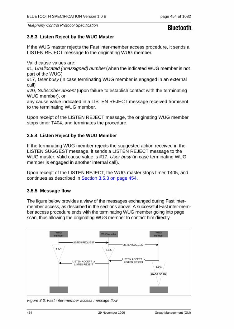
BLUETOOTH SPECIFICATION Version 1.0 B page 454 of 1082
Telephony Control Protocol Specification
3.5.3 Listen Reject by the WUG Master
If the WUG master rejects the Fast inter-member access procedure, it sends a LISTEN REJECT message to the originating WUG member.
Valid cause values are:#1, Unallocated (unassigned) number (when the indicated WUG member is not part of the WUG) #17, User busy (in case terminating WUG member is engaged in an external call) #20, Subscriber absent (upon failure to establish contact with the terminating WUG member), or any cause value indicated in a LISTEN REJECT message received from/sent to the terminating WUG member.
Upon receipt of the LISTEN REJECT message, the originating WUG member stops timer T404, and terminates the procedure.
3.5.4 Listen Reject by the WUG Member
If the terminating WUG member rejects the suggested action received in the LISTEN SUGGEST message, it sends a LISTEN REJECT message to the WUG master. Valid cause value is #17, User busy (in case terminating WUG member is engaged in another internal call).
Upon receipt of the LISTEN REJECT, the WUG master stops timer T405, and continues as described in Section 3.5.3 on page 454.
3.5.5 Message flow
The figure below provides a view of the messages exchanged during Fast inter-member access, as described in the sections above. A successful Fast inter-mem-ber access procedure ends with the terminating WUG member going into page scan, thus allowing the originating WUG member to contact him directly.
Figure 3.3: Fast inter-member access message flow
T406
WUGmember
LISTEN REQUEST
LISTEN ACCEPT orLISTEN REJECT
T404
WUGmember
WUG master
LISTEN SUGGEST
T405
LISTEN ACCEPT orLISTEN REJECT
PAGE SCAN
454 29 November 1999 Group Management (GM)
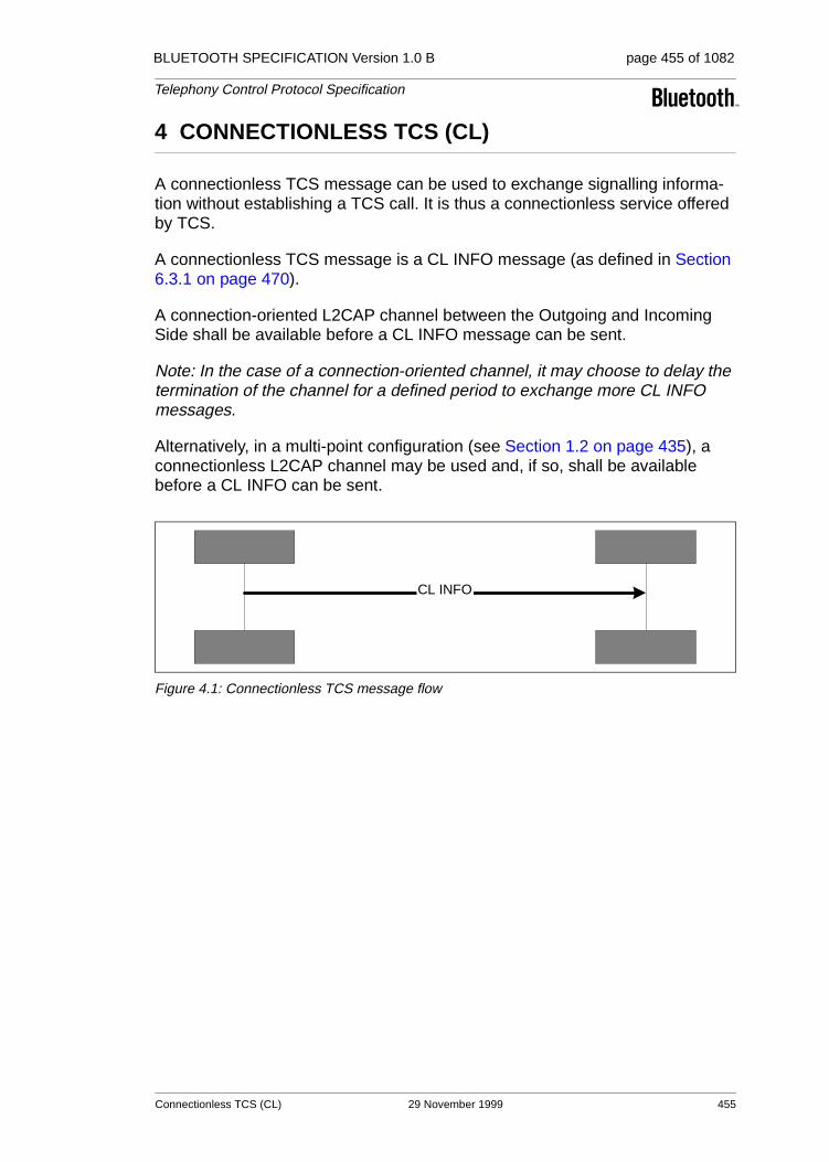
BLUETOOTH SPECIFICATION Version 1.0 B page 455 of 1082
Telephony Control Protocol Specification
4 CONNECTIONLESS TCS (CL)
A connectionless TCS message can be used to exchange signalling informa-tion without establishing a TCS call. It is thus a connectionless service offered by TCS.
A connectionless TCS message is a CL INFO message (as defined in Section 6.3.1 on page 470).
A connection-oriented L2CAP channel between the Outgoing and Incoming Side shall be available before a CL INFO message can be sent.
Note: In the case of a connection-oriented channel, it may choose to delay the termination of the channel for a defined period to exchange more CL INFO messages.
Alternatively, in a multi-point configuration (see Section 1.2 on page 435), a connectionless L2CAP channel may be used and, if so, shall be available before a CL INFO can be sent.
Figure 4.1: Connectionless TCS message flow
CL INFO
Connectionless TCS (CL) 29 November 1999 455

BLUETOOTH SPECIFICATION Version 1.0 B page 456 of 1082
Telephony Control Protocol Specification
5 SUPPLEMENTARY SERVICES (SS)
The TCS provides explicit support for only one supplementary service, the Calling Line Identity (seeSection 5.1 on page 456).
For supplementary services provided by an external network, using DTMF sequences for the activation/de-activation and interrogation of supplementary services, the DTMF start & stop procedure is supported (see Section 5.2 on page 456). This procedure allows both finite and infinite tone lengths.
Section 5.3 on page 458 specifies how a specific supplementary service, pro-vided by an external network, called register recall is supported.
For other means of supplementary service control, no explicit support is speci-fied. Support may be realized by either using the service call, or use the com-pany specific information element, or a combination.
5.1 CALLING LINE IDENTITY
To inform the Incoming Side of the identity of the originator of the call, the Out-going Side may include the calling party number information element (see Section 7.4.6 on page 481) in the SETUP message transferred as part of the call request.
Figure 5.1: Calling line identity message flow
5.2 DTMF START & STOP
The DTMF start & stop procedure is supported to provide supplementary ser-vice control on PSTN type of networks.
In principle DTMF messages can be initiated by either (Outgoing or Incoming) Side; in practice, however, the Side (gateway) connected to the external PSTN network will be the recipient.
DTMF messages can be transmitted only in the active state of a call. Tone generation shall end when the call is disconnected.
OutgoingSide Incoming Side
SETUP {Calling Party Number}
456 29 November 1999 Supplementary Services (SS)
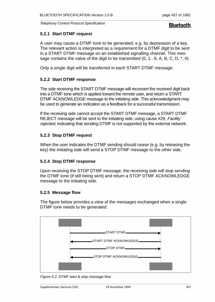
BLUETOOTH SPECIFICATION Version 1.0 B page 457 of 1082
Telephony Control Protocol Specification
5.2.1 Start DTMF request
A user may cause a DTMF tone to be generated; e.g. by depression of a key. The relevant action is interpreted as a requirement for a DTMF digit to be sent in a START DTMF message on an established signalling channel. This mes-sage contains the value of the digit to be transmitted (0, 1...9, A, B, C, D, *, #).
Only a single digit will be transferred in each START DTMF message.
5.2.2 Start DTMF response
The side receiving the START DTMF message will reconvert the received digit back into a DTMF tone which is applied toward the remote user, and return a START DTMF ACKNOWLEDGE message to the initiating side. This acknowledgment may be used to generate an indication as a feedback for a successful transmission.
If the receiving side cannot accept the START DTMF message, a START DTMF REJECT message will be sent to the initiating side, using cause #29, Facility rejected, indicating that sending DTMF is not supported by the external network.
5.2.3 Stop DTMF request
When the user indicates the DTMF sending should cease (e.g. by releasing the key) the initiating side will send a STOP DTMF message to the other side.
5.2.4 Stop DTMF response
Upon receiving the STOP DTMF message, the receiving side will stop sending the DTMF tone (if still being sent) and return a STOP DTMF ACKNOWLEDGE message to the initiating side.
5.2.5 Message flow
The figure below provides a view of the messages exchanged when a single DTMF tone needs to be generated.
Figure 5.2: DTMF start & stop message flow
START DTMF
START DTMF ACKNOWLEDGE
STOP DTMF
STOP DTMF ACKNOWLEDGE
Supplementary Services (SS) 29 November 1999 457
BLUETOOTH SPECIFICATION Version 1.0 B page 458 of 1082
Telephony Control Protocol Specification
5.3 REGISTER RECALL
Register recall means to seize a register (with dial tone) to permit input of fur-ther digits or other action. In some markets, this is referred to as ’hook flash’. Register recall is supported by sending an INFORMATION message with a keypad facility information element, indicating ’register recall’ (value 16H). Fur-ther digits are sent using the procedures as indicated in Section 5.2 above.
458 29 November 1999 Supplementary Services (SS)
BLUETOOTH SPECIFICATION Version 1.0 B page 459 of 1082
Telephony Control Protocol Specification
6 MESSAGE FORMATS
This section provides an overview of the structure of messages used in this specification, and defines the function and information contents (i.e. semantics) of each message.
Whenever a message is sent according to the procedures of Sections 2, 3 and 4, it shall contain the mandatory information elements, and optionally any com-bination of the optional information elements specified in this section for that message.
A message shall always be delivered in a single L2CAP packet. The start of a message (the LSB of the first octet) shall be aligned with the start of the L2CAP payload.
Each definition includes:
a) A brief description of the message direction and use
b) A table listing the information elements in order of their appearance in the message (same relative order for all message types)
c) Indications for each information element in the table, specifying – • the section of this specification describing the information element
• whether inclusion in mandatory (’M’) or optional (’O’)
• the length (or length range) of the information element, where ’*’ denotes an undefined maximum length which may be application dependent.
d) Further explanatory notes, as necessary
All message formats are denoted in octets.
Message formats 29 November 1999 459

BLUETOOTH SPECIFICATION Version 1.0 B page 460 of 1082
Telephony Control Protocol Specification
6.1 CALL CONTROL MESSAGE FORMATS
6.1.1 ALERTING
This message is sent by the incoming side to indicate that the called user alert-ing has been initiated.
6.1.2 CALL PROCEEDING
This message is sent by the incoming side to indicate that the requested call establishment has been initiated and no more call establishment information will be accepted.
Message Type: ALERTING
Direction: incoming to outgoing
Information Element Ref. Type Length
Message type 7.3 M 1
Bearer capability 7.4.3 O Note 1)
Note 1: Allowed only in the first message sent by the incoming side.
4(26)
Progress indicator 7.4.13 O 2
SCO Handle 7.4.14 O 2
Destination CID 7.4.11 O 4
Company specific 7.4.9 O 3-*
Table 6.1: ALERTING message content
Message Type: CALL PROCEEDING
Direction: incoming to outgoing
Information Element Ref. Type Length
Message type 7.3 M 1
Bearer capability 7.4.3 O Note 1)
Note 1: Allowed only in the first message sent by the incoming side.
4(26)
Progress indicator 7.4.13 O 2
SCO Handle 7.4.14 O 2
Destination CID 7.4.11 O 4
Company specific 7.4.9 O 3-*
Table 6.2: CALL PROCEEDING message content
460 29 November 1999 Message formats

BLUETOOTH SPECIFICATION Version 1.0 B page 461 of 1082
Telephony Control Protocol Specification
6.1.3 CONNECT
This message is sent by the incoming side to indicate call acceptance by the called user.
6.1.4 CONNECT ACKNOWLEDGE
This message is sent by the outgoing side to acknowledge the receipt of a CONNECT message.
Message Type: CONNECT
Direction: incoming to outgoing
Information Element Ref. Type Length
Message type 7.3 M 1
Bearer capability 7.4.3 ONote 1)
Note 1: Allowed only in the first message sent by the incoming side.
4(26)
SCO Handle 7.4.14 O 2
Company specific 7.4.9 O 3-*
Table 6.3: CONNECT message content
Message Type: CONNECT ACKNOWLEDGE
Direction: outgoing to incoming
Information Element Ref. Type Length
Message type 7.3 M 1
SCO Handle 7.4.14 O 2
Destination CID 7.4.11 O 4
Company specific 7.4.9 O 3-*
Table 6.4: CONNECT ACKNOWLEDGE message content
Message formats 29 November 1999 461

BLUETOOTH SPECIFICATION Version 1.0 B page 462 of 1082
Telephony Control Protocol Specification
6.1.5 DISCONNECT
This message is sent by either side as an invitation to terminate the call.
6.1.6 INFORMATION
This message is sent by either side to provide additional information during call establishment (in case of overlap sending).
Message Type: DISCONNECT
Direction: both
Information Element Ref. Type Length
Message type 7.3 M 1
Cause 7.4.7 O 2
Progress indicator 7.4.13 O 2
SCO Handle 7.4.14 O 2
Destination CID 7.4.11 O 4
Company specific 7.4.9 O 3-*
Table 6.5: DISCONNECT message content
Message Type: INFORMATION
Direction: both
Information Element Ref. Type Length
Message type 7.3 M 1
Sending complete 7.4.15 O 1
Keypad facility 7.4.12 O 2
Called party number 7.4.5 O 3-*
Audio control 7.4.2 O 3-*
Company specific 7.4.9 O 3-*
Table 6.6: INFORMATION message content
462 29 November 1999 Message formats
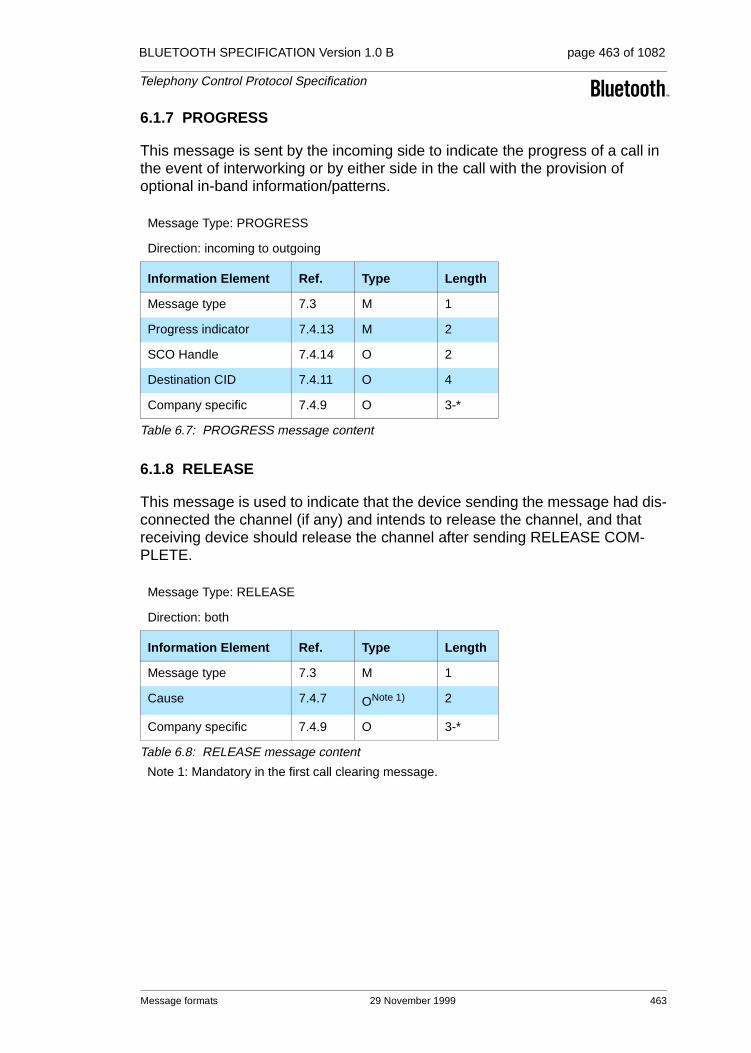
BLUETOOTH SPECIFICATION Version 1.0 B page 463 of 1082
Telephony Control Protocol Specification
6.1.7 PROGRESS
This message is sent by the incoming side to indicate the progress of a call in the event of interworking or by either side in the call with the provision of optional in-band information/patterns.
6.1.8 RELEASE
This message is used to indicate that the device sending the message had dis-connected the channel (if any) and intends to release the channel, and that receiving device should release the channel after sending RELEASE COM-PLETE.
Message Type: PROGRESS
Direction: incoming to outgoing
Information Element Ref. Type Length
Message type 7.3 M 1
Progress indicator 7.4.13 M 2
SCO Handle 7.4.14 O 2
Destination CID 7.4.11 O 4
Company specific 7.4.9 O 3-*
Table 6.7: PROGRESS message content
Message Type: RELEASE
Direction: both
Information Element Ref. Type Length
Message type 7.3 M 1
Cause 7.4.7 ONote 1)
Note 1: Mandatory in the first call clearing message.
2
Company specific 7.4.9 O 3-*
Table 6.8: RELEASE message content
Message formats 29 November 1999 463
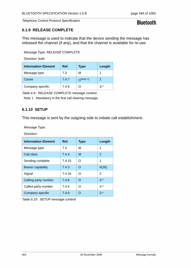
BLUETOOTH SPECIFICATION Version 1.0 B page 464 of 1082
Telephony Control Protocol Specification
6.1.9 RELEASE COMPLETE
This message is used to indicate that the device sending the message has released the channel (if any), and that the channel is available for re-use.
6.1.10 SETUP
This message is sent by the outgoing side to initiate call establishment.
Message Type: RELEASE COMPLETE
Direction: both
Information Element Ref. Type Length
Message type 7.3 M 1
Cause 7.4.7 ONote 1)
Note 1: Mandatory in the first call clearing message.
2
Company specific 7.4.9 O 3-*
Table 6.9: RELEASE COMPLETE message content
Message Type:
Direction:
Information Element Ref. Type Length
Message type 7.3 M 1
Call class 7.4.4 M 2
Sending complete 7.4.15 O 1
Bearer capability 7.4.3 O 4(26)
Signal 7.4.16 O 2
Calling party number 7.4.6 O 3-*
Called party number 7.4.5 O 3-*
Company specific 7.4.9 O 3-*
Table 6.10: SETUP message content
464 29 November 1999 Message formats

BLUETOOTH SPECIFICATION Version 1.0 B page 465 of 1082
Telephony Control Protocol Specification
6.1.11 SETUP ACKNOWLEDGE
This message is sent by the incoming side to indicate that call establishment has been initiated, but additional information may be required.
6.1.12 Start DTMF
This message contains the digit the other side should reconvert back into a DTMF tone, which is then applied towards the remote user.
Message Type: SETUP ACKNOWLEDGE
Direction: incoming to outgoing
Information Element Ref. Type Length
Message type 7.3 M 1
Bearer capability 7.4.3 ONote 1)
Note 1: Allowed only in the first message sent by the incoming side.
4(26)
Progress indicator 7.4.13 O 2
SCO Handle 7.4.14 O 2
Destination CID 7.4.11 O 4
Company specific 7.4.9 O 3-*
Table 6.11: SETUP ACKNOWLEDGE message content
Message Type: Start DTMF
Direction: both
Information Element Ref. Type Length
Message type 7.3 M 1
Keypad facility 7.4.12 M 2
Table 6.12: Start DTMF message content
Message formats 29 November 1999 465

BLUETOOTH SPECIFICATION Version 1.0 B page 466 of 1082
Telephony Control Protocol Specification
6.1.13 Start DTMF Acknowledge
This message is sent to indicate the successful initiation of the action required by the Start DTMF message.
6.1.14 Start DTMF Reject
This message is sent to indicate that the other side cannot accept the Start DTMF message.
6.1.15 Stop DTMF
This message is used to stop the DTMF tone sent towards the remote user.
Message Type: Start DTMF Acknowledge
Direction: both
Information Element Ref. Type Length
Message type 7.3 M 1
Keypad facility 7.4.12 M 2
Table 6.13: Start DTMF Acknowledge message content
Message Type: Start DTMF Reject
Direction: both
Information Element Ref. Type Length
Message type 7.3 M 1
Cause 7.4.7 O 2
Table 6.14: Start DTMF Reject message content
Message Type: Stop DTMF
Direction: both
Information Element Ref. Type Length
Message type 7.3 M 1
Table 6.15: Stop DTMF message content
466 29 November 1999 Message formats

BLUETOOTH SPECIFICATION Version 1.0 B page 467 of 1082
Telephony Control Protocol Specification
6.1.16 Stop DTMF Acknowledge
This message is sent to indicate that the sending of the DTMF tone has been stopped.
6.2 GROUP MANAGEMENT MESSAGE FORMATS
6.2.1 ACCESS RIGHTS REQUEST
This message is sent by the initiating side to obtain access rights.
6.2.2 ACCESS RIGHTS ACCEPT
This message is sent by the responding side to indicate granting of access rights.
Message Type: Stop DTMF Acknowledge
Direction: both
Information Element Ref. Type Length
Message type 7.3 M 1
Keypad facility 7.4.12 M 2
Table 6.16: Stop DTMF Acknowledge message content
Message Type: ACCESS RIGHTS REQUEST
Direction:
Information Element Ref. Type Length
Message type 7.3 M 1
Company specific 7.4.9 O 3-*
Table 6.17: ACCESS RIGHTS REQUEST message content
Message Type: ACCESS RIGHTS ACCEPT
Direction:
Information Element Ref. Type Length
Message type 7.3 M 1
Company specific 7.4.9 O 3-*
Table 6.18: ACCESS RIGHTS ACCEPT message content
Message formats 29 November 1999 467

BLUETOOTH SPECIFICATION Version 1.0 B page 468 of 1082
Telephony Control Protocol Specification
6.2.3 ACCESS RIGHTS REJECT
This message is sent by the responding side to indicate denial of access rights.
6.2.4 INFO SUGGEST
This message is sent by the WUG master to indicate that a change has occurred in the WUG configuration.
6.2.5 INFO ACCEPT
This message is sent by the WUG member to indicate the acceptance of the updated WUG configuration.
Message Type: ACCESS RIGHTS REJECT
Direction:
Information Element Ref. Type Length
Message type 7.3 M 1
Company specific 7.4.9 O 3-*
Table 6.19: ACCESS RIGHTS REJECT message content
Message Type: INFO SUGGEST
Direction: WUG master to WUG member
Information Element Ref. Type Length
Message type 7.3 M 1
Configuration Data 7.4.10 M *
Company specific 7.4.9 O 3-*
Table 6.20: INFO SUGGEST message content
Message Type: INFO ACCEPT
Direction: WUG member to WUG master
Information Element Ref. Type Length
Message type 7.3 M 1
Company specific 7.4.9 O 3-*
Table 6.21: INFO ACCEPT message content
468 29 November 1999 Message formats

BLUETOOTH SPECIFICATION Version 1.0 B page 469 of 1082
Telephony Control Protocol Specification
6.2.6 LISTEN REQUEST
This message is sent by a WUG member to indicate to the WUG master the request for a Fast inter-member access to the indicated WUG member.
6.2.7 LISTEN SUGGEST
This message is sent by a WUG master to indicate to the WUG member the request for a Fast inter-member access.
6.2.8 LISTEN ACCEPT
This message is sent to indicate the acceptance of the previous request for a Fast inter-member access.
Message Type: LISTEN REQUEST
Direction: WUG member to WUG master
Information Element Ref. Type Length
Message type 7.3 M 1
Called party number 7.4.6 M 3-*
Company specific 7.4.9 O 3-*
Table 6.22: LISTEN REQUEST message content
Message Type: LISTEN SUGGEST
Direction: WUG master to WUG member
Information Element Ref. Type Length
Message type 7.3 M 1
Company specific 7.4.9 O 3-*
Table 6.23: LISTEN SUGGEST message content
Message Type: LISTEN ACCEPT
Direction: both
Information Element Ref. Type Length
Message type 7.3 M 1
Clock offset 7.4.8 O 4
Company specific 7.4.9 O 3-*
Table 6.24: LISTEN ACCEPT message content
Message formats 29 November 1999 469
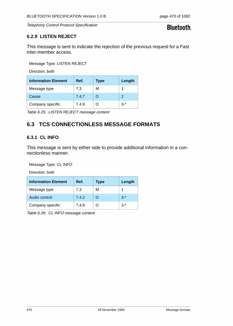
BLUETOOTH SPECIFICATION Version 1.0 B page 470 of 1082
Telephony Control Protocol Specification
6.2.9 LISTEN REJECT
This message is sent to indicate the rejection of the previous request for a Fast inter-member access.
6.3 TCS CONNECTIONLESS MESSAGE FORMATS
6.3.1 CL INFO
This message is sent by either side to provide additional information in a con-nectionless manner.
Message Type: LISTEN REJECT
Direction: both
Information Element Ref. Type Length
Message type 7.3 M 1
Cause 7.4.7 O 2
Company specific 7.4.9 O 3-*
Table 6.25: LISTEN REJECT message content
Message Type: CL INFO
Direction: both
Information Element Ref. Type Length
Message type 7.3 M 1
Audio control 7.4.2 O 3-*
Company specific 7.4.9 O 3-*
Table 6.26: CL INFO message content
470 29 November 1999 Message formats

BLUETOOTH SPECIFICATION Version 1.0 B page 471 of 1082
Telephony Control Protocol Specification
7 MESSAGE CODING
The figures and text in this section describe message contents. Within each octet, the bit designated ’bit 1’ is transmitted first, followed by bit 2, 3, 4, etc. Similarly, the octet shown at the top of the figure is sent first.
Whenever a message is sent, according to the procedures of Sections 2, 3 and 4, it shall be coded as specified in this section.
7.1 OVERVIEW
The coding rules follow ITU-T Recommendation Q.931, but is tailored to the specific needs of TCS.
Every message consists of:
a) Protocol discriminator
b) Message type, and
c) Other information elements, as required
The Protocol discriminator and Message type is part of every TCS message, while the other information elements are specific to each message type.
A particular information element shall be present only once in a given mes-sage.
The term ’default’ implies that the value defined shall be used in the absence of any assignment or negotiation of alternative values.
For notation purposes – when a field extends over more than one octet, the order of bit values progressively decreases as the octet number increases. The least significant bit of the field is represented by the lowest numbered bit of the highest-numbered octet of the field. In general, bit 1 of each octet contains the least significant bit of a field.
8 7 6 5 4 3 2 1
Protocol discriminator Message type octet 1
Other information elements as required octet 2
Table 7.1: General message format
Message coding 29 November 1999 471

BLUETOOTH SPECIFICATION Version 1.0 B page 472 of 1082
Telephony Control Protocol Specification
7.2 PROTOCOL DISCRIMINATOR
The purpose of the protocol discriminator is to distinguish the TCS messages into different functional groups. The protocol discriminator is the first part of every message.
The protocol discriminator is coded according to Figure 7.1 and Table 7.2.
Figure 7.1: Protocol discriminator
7.3 MESSAGE TYPE
The purpose of the message type is to identify the function of the message being sent.
The Message type is the first part of every message and it is coded as shown in Figure 7.2 and Table 7.3.
Figure 7.2: Message type
8 7 6 5 4 3 2 1
Protocol discriminator octet 1
Bits
8 7 60 0 0 Bluetooth TCS Call Control0 0 1 Bluetooth TCS Group management0 1 0 Bluetooth TCS ConnectionlessAll other values reserved
Table 7.2: Protocol discriminator
8 7 6 5 4 3 2 1
Message type octet 1
Bits
5 4 3 2 1
Call Control messages
Call Establishment
0 0 0 0 0 ALERTING
Table 7.3: Message type
472 29 November 1999 Message coding
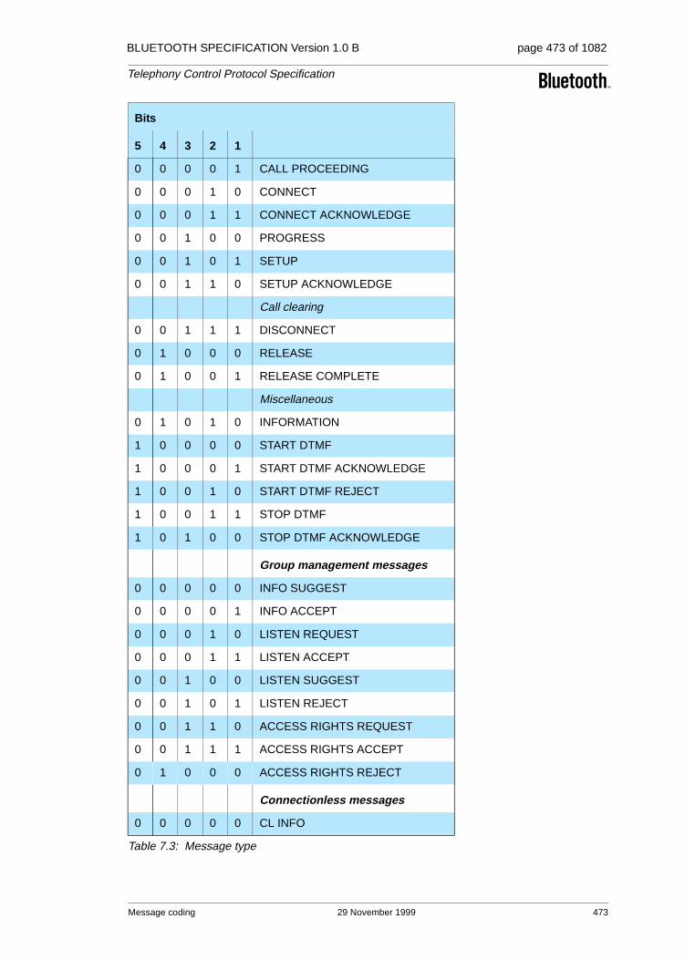
BLUETOOTH SPECIFICATION Version 1.0 B page 473 of 1082
Telephony Control Protocol Specification
0 0 0 0 1 CALL PROCEEDING
0 0 0 1 0 CONNECT
0 0 0 1 1 CONNECT ACKNOWLEDGE
0 0 1 0 0 PROGRESS
0 0 1 0 1 SETUP
0 0 1 1 0 SETUP ACKNOWLEDGE
Call clearing
0 0 1 1 1 DISCONNECT
0 1 0 0 0 RELEASE
0 1 0 0 1 RELEASE COMPLETE
Miscellaneous
0 1 0 1 0 INFORMATION
1 0 0 0 0 START DTMF
1 0 0 0 1 START DTMF ACKNOWLEDGE
1 0 0 1 0 START DTMF REJECT
1 0 0 1 1 STOP DTMF
1 0 1 0 0 STOP DTMF ACKNOWLEDGE
Group management messages
0 0 0 0 0 INFO SUGGEST
0 0 0 0 1 INFO ACCEPT
0 0 0 1 0 LISTEN REQUEST
0 0 0 1 1 LISTEN ACCEPT
0 0 1 0 0 LISTEN SUGGEST
0 0 1 0 1 LISTEN REJECT
0 0 1 1 0 ACCESS RIGHTS REQUEST
0 0 1 1 1 ACCESS RIGHTS ACCEPT
0 1 0 0 0 ACCESS RIGHTS REJECT
Connectionless messages
0 0 0 0 0 CL INFO
Bits
5 4 3 2 1
Table 7.3: Message type
Message coding 29 November 1999 473
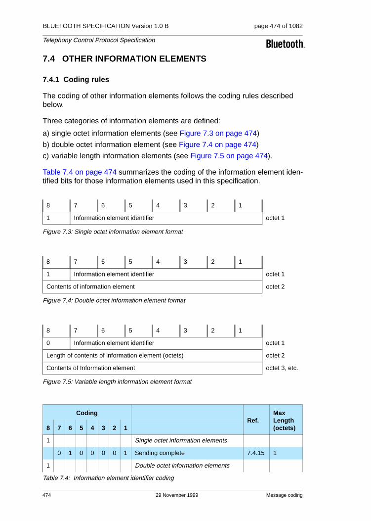
BLUETOOTH SPECIFICATION Version 1.0 B page 474 of 1082
Telephony Control Protocol Specification
7.4 OTHER INFORMATION ELEMENTS
7.4.1 Coding rules
The coding of other information elements follows the coding rules described below.
Three categories of information elements are defined:
a) single octet information elements (see Figure 7.3 on page 474)
b) double octet information element (see Figure 7.4 on page 474)
c) variable length information elements (see Figure 7.5 on page 474).
Table 7.4 on page 474 summarizes the coding of the information element iden-tified bits for those information elements used in this specification.
Figure 7.3: Single octet information element format
Figure 7.4: Double octet information element format
Figure 7.5: Variable length information element format
8 7 6 5 4 3 2 1
1 Information element identifier octet 1
8 7 6 5 4 3 2 1
1 Information element identifier octet 1
Contents of information element octet 2
8 7 6 5 4 3 2 1
0 Information element identifier octet 1
Length of contents of information element (octets) octet 2
Contents of Information element octet 3, etc.
CodingRef.
Max Length (octets)8 7 6 5 4 3 2 1
1 Single octet information elements
0 1 0 0 0 0 1 Sending complete 7.4.15 1
1 Double octet information elements
Table 7.4: Information element identifier coding
474 29 November 1999 Message coding

BLUETOOTH SPECIFICATION Version 1.0 B page 475 of 1082
Telephony Control Protocol Specification
The descriptions of the information elements below are organized in alphabeti-cal order. However, there is a particular order of appearance for each informa-tion element in a message. The code values of the information element identifier for the variable length formats are assigned in ascending numerical order, according to the actual order of appearance of each information element in a message. This allows the receiving devices to detect the presence or absence of a particular information element without scanning through an entire message.
Where the description of information elements in this specification contains spare bits, these bits are indicated as being set to ’0’. In order to allow compat-ibility with future implementation, messages should not be rejected simply because a spare bit is set to ’1’.
The second octet of a variable length information element indicates the total length of the contents of that information element regardless of the coding of the first octet (i.e. the length is calculated starting from octet 3). It is the binary coding of the number of octets of the contents, with bit 1 as the least significant bit (2°).
An optional variable-length information element may be present, but empty (zero length). The receiver should interpret this as if that information element
1 0 0 0 0 0 0 Call class 7.4.4 2
1 0 0 0 0 0 1 Cause 7.4.7 2
1 0 0 0 0 1 0 Progress indicator 7.4.13 2
1 0 0 0 0 1 1 Signal 7.4.16 2
1 0 0 0 1 0 0 Keypad facility 7.4.12 2
1 0 0 0 1 0 1 SCO handle 7.4.14 2
0 Variable length information elements
0 0 0 0 0 0 0 Clock offset 7.4.8 4
0 0 0 0 0 0 1 Configuration data 7.4.2 *
0 0 0 0 0 1 0 Bearer capability 7.4.3 4(26)
0 0 0 0 0 1 1 Destination CID 7.4.11 4
0 0 0 0 1 0 0 Calling party number 7.4.6 *
0 0 0 0 1 0 1 Called party number 7.4.5 *
0 0 0 0 1 1 0 Audio control 7.4.2 *
0 0 0 0 1 1 1 Company specific 7.4.9 *
CodingRef.
Max Length (octets)8 7 6 5 4 3 2 1
Table 7.4: Information element identifier coding
Message coding 29 November 1999 475

BLUETOOTH SPECIFICATION Version 1.0 B page 476 of 1082
Telephony Control Protocol Specification
was absent. Similarly, an absent information element should be interpreted by the receiver as if that information element was empty.
7.4.2 Audio control
The purpose of the Audio control information elements is to indicate informa-tion relating to the control of audio.
Figure 7.6:
7.4.3 Bearer capability
The purpose of the Bearer capability information elements is to indicate a requested or available bearer service.
If this information element is absent, the default Bearer capability is Link type Synchronous Connection-Oriented with packet type HV3, using CVSD coding for the User information layer 1.
Figure 7.7:
Link type element coding = 00000000 (SCO)
8 7 6 5 4 3 2 1 Octets
0 0 0 0 0 1 1 0 1
Length of contents of information element (octets) 2
Control information 3
Control information (octet 3)Bits
7 6 5 4 3 2 10 0 0 0 0 0 0 Volume increase0 0 0 0 0 0 1 Volume decrease0 0 0 0 0 1 0 Microphone gain increase0 0 0 0 0 1 1 Microphone gain decrease0 X X X X X X Reserved for Bluetooth standardization1 X X X X X X Company specific
Table 7.5: Audio Control information element coding
8 7 6 5 4 3 2 1 Octets
0 0 0 0 0 0 1 0 1
Length of contents of information element (octets) 2
Link type 3
476 29 November 1999 Message coding

BLUETOOTH SPECIFICATION Version 1.0 B page 477 of 1082
Telephony Control Protocol Specification
Figure 7.8:
Link type element coding = 00000001 (ACL)
Figure 7.9:
Note: the Quality of Service is repeated at TCS level, as only TCS has the knowledge of end-to-end Quality of Service requirements.
User information layer 1 Packet type 4
Flags 4
Service type 5
6
Token Rate 7
8
9
10
Token Bucket Size (bytes) 11
12
13
14
Peak Bandwidth (bytes/second) 15
16
17
18
Latency (microseconds) 19
20
21
22
Delay Variation (microseconds) 23
24
25
User information layer 3 User information layer 2 26
Message coding 29 November 1999 477

BLUETOOTH SPECIFICATION Version 1.0 B page 478 of 1082
Telephony Control Protocol Specification
Link type (octet 3)
Bits8 7 6 5 4 3 2 10 0 0 0 0 0 0 0 Synchronous Connection-Oriented0 0 0 0 0 0 0 1 Asynchronous Connection-Less0 0 0 0 0 0 1 0 None
All other values are reserved
Octet 4 coding (Link type element coding = 000000000)
Packet type (octet 4)
Bits 5 4 3 2 1
0 0 1 0 1 HV10 0 1 1 0 HV20 0 1 1 1 HV30 1 0 0 0 DVAll other values are reserved
User information layer 1 (octet 4)
Bits8 7 60 0 1 CVSD0 1 0 PCM A-law0 1 1 PCM µ-lawAll other values reserved
Octets 4-26 coding (Link type element coding = 000000001)
The details of the coding Octets 4-25 can be found in L2CAP, see L2CAP, Section 6 on page 289
User information layer 2 (octet 26)
Bits 4 3 2 1
0 0 0 0 RFCOMM over L2CAPAll other values are reserved
User information layer 3 (octet 26)
Bits8 7 6 50 0 0 0 Not specified0 0 0 1 PPP0 0 1 0 IPAll other values reserved
Octet 4 coding (Link type element coding = 000000010)
Octet 4 is absent
Table 7.6: Bearer capability information element coding
478 29 November 1999 Message coding

BLUETOOTH SPECIFICATION Version 1.0 B page 479 of 1082
Telephony Control Protocol Specification
7.4.4 Call class
The purpose of the Call class is to indicate the basic aspects of the service requested. This element allows the user to indicate the use of default attributes, thereby reducing the length of the set-up message.
Figure 7.10:
Note
• An external call is a call to/from an external network; e.g. the PSTN.
• An intercom call is a call between Bluetooth devices.
• A service call is a call for configuration purposes.
• An emergency call is an external call using a dedicated emergency call number, using specific properties.
8 7 6 5 4 3 2 1 Octets
1 1 0 0 0 0 0 0 1
Call Class 2
Call class (octet 2)
Bits8 7 6 5 4 3 2 10 0 0 0 0 0 0 0 External call 0 0 0 0 0 0 0 1 Intercom call0 0 0 0 0 0 1 0 Service call0 0 0 0 0 0 1 1 Emergency call
All other values reserved
Table 7.7: Call class information element coding
Message coding 29 November 1999 479
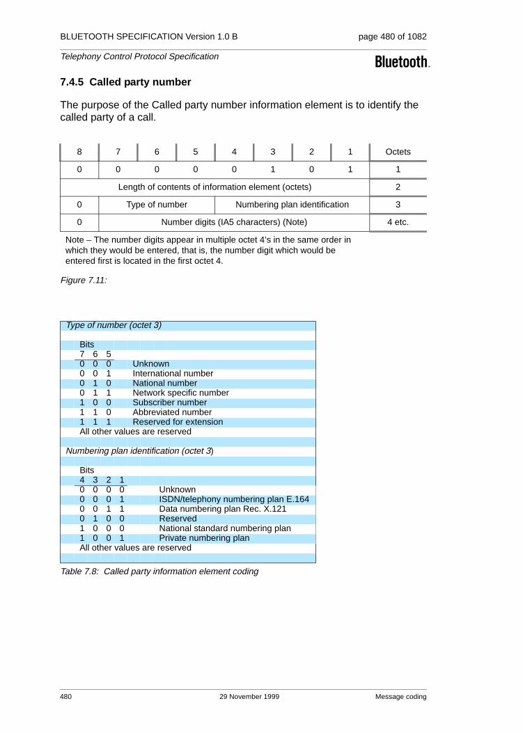
BLUETOOTH SPECIFICATION Version 1.0 B page 480 of 1082
Telephony Control Protocol Specification
7.4.5 Called party number
The purpose of the Called party number information element is to identify the called party of a call.
Figure 7.11:
8 7 6 5 4 3 2 1 Octets
0 0 0 0 0 1 0 1 1
Length of contents of information element (octets) 2
0 Type of number Numbering plan identification 3
0 Number digits (IA5 characters) (Note) 4 etc.
Note – The number digits appear in multiple octet 4’s in the same order in which they would be entered, that is, the number digit which would be entered first is located in the first octet 4.
Type of number (octet 3)
Bits7 6 50 0 0 Unknown0 0 1 International number0 1 0 National number 0 1 1 Network specific number1 0 0 Subscriber number1 1 0 Abbreviated number1 1 1 Reserved for extensionAll other values are reserved
Numbering plan identification (octet 3)
Bits4 3 2 10 0 0 0 Unknown0 0 0 1 ISDN/telephony numbering plan E.1640 0 1 1 Data numbering plan Rec. X.1210 1 0 0 Reserved 1 0 0 0 National standard numbering plan1 0 0 1 Private numbering planAll other values are reserved
Table 7.8: Called party information element coding
480 29 November 1999 Message coding

BLUETOOTH SPECIFICATION Version 1.0 B page 481 of 1082
Telephony Control Protocol Specification
7.4.6 Calling party number
The purpose of the Calling party number information element is to identify the origin of a call.
Figure 7.12:
8 7 6 5 4 3 2 1 Octets
0 0 0 0 0 1 0 0 1
Length of contents of information element (octets) 2
0 Type of number Numbering plan identification 3
0Presentation
indicator0 0 0
Screening indicator
4
0 Number digits (IA5 characters) 5 etc.
Type of number (octet 3)
Bits7 6 50 0 0 Unknown0 0 1 International number0 1 0 National number 0 1 1 Network specific number1 0 0 Subscriber number1 1 0 Abbreviated number1 1 1 Reserved for extensionAll other values are reserved
Numbering plan identification (octet 3)
Bits4 3 2 10 0 0 0 Unknown0 0 0 1 ISDN/telephony numbering plan E.1640 0 1 1 Data numbering plan Rec. X.1210 1 0 0 Reserved 1 0 0 0 National standard numbering plan1 0 0 1 Private numbering planAll other values are reserved
Presentation indicator (octet 4)
Bits7 60 0 Presentation allowed0 1 Presentation restricted1 0 Number not available due to interworking1 1 ReservedAll other values are reserved
Table 7.9: Calling party information element coding
Message coding 29 November 1999 481
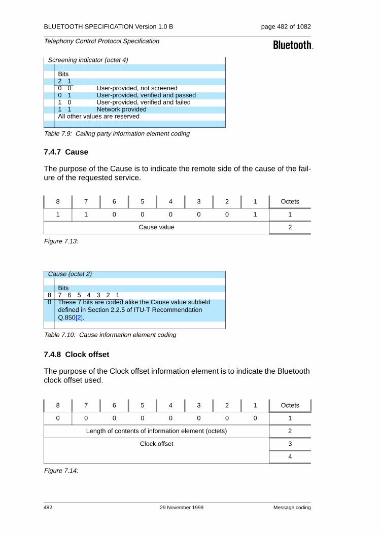
BLUETOOTH SPECIFICATION Version 1.0 B page 482 of 1082
Telephony Control Protocol Specification
7.4.7 Cause
The purpose of the Cause is to indicate the remote side of the cause of the fail-ure of the requested service.
Figure 7.13:
7.4.8 Clock offset
The purpose of the Clock offset information element is to indicate the Bluetooth clock offset used.
Figure 7.14:
Screening indicator (octet 4)
Bits2 10 0 User-provided, not screened0 1 User-provided, verified and passed1 0 User-provided, verified and failed1 1 Network providedAll other values are reserved
8 7 6 5 4 3 2 1 Octets
1 1 0 0 0 0 0 1 1
Cause value 2
Cause (octet 2)
Bits8 7 6 5 4 3 2 10 These 7 bits are coded alike the Cause value subfield
defined in Section 2.2.5 of ITU-T Recommendation Q.850[2].
Table 7.10: Cause information element coding
8 7 6 5 4 3 2 1 Octets
0 0 0 0 0 0 0 0 1
Length of contents of information element (octets) 2
Clock offset 3
4
Table 7.9: Calling party information element coding
482 29 November 1999 Message coding

BLUETOOTH SPECIFICATION Version 1.0 B page 483 of 1082
Telephony Control Protocol Specification
7.4.9 Company specific
The purpose of the Company specific information element is to send non-standardized information.
Figure 7.15:
Clock offset coding (octet 3 and 4)
Bits (octet 3)
Bits (octet 4)
8 7 6 5 4 3 2 1 8 7 6 5 4 3 2 10 Contains bits 16-2 of Bluetooth clock
Table 7.11: Clock offset information element coding
8 7 6 5 4 3 2 1 Octets
0 0 0 0 0 1 1 1 1
Length of contents of information element (octets) 2
Company Identification 3
Company Identification 4
Company specific contents
L+2
Company identification coding (octet 3 and octet 4)
Bits (octet 3)
Bits (octet 4)
8 7 6 5 4 3 2 1 8 7 6 5 4 3 2 10 0 0 0 0 0 0 0 0 0 0 0 0 0 0 0 Ericsson
0 0 0 0 0 0 0 0 0 0 0 0 0 0 0 1Nokia Mobile Phones
0 0 0 0 0 0 0 0 0 0 0 0 0 0 1 0Intel Corporation
0 0 0 0 0 0 0 0 0 0 0 0 0 0 1 1IBM Corporation
0 0 0 0 0 0 0 0 0 0 0 0 0 1 0 0Toshiba Corporation
All other values are reserved
Table 7.12: Company specific information element coding
Message coding 29 November 1999 483

BLUETOOTH SPECIFICATION Version 1.0 B page 484 of 1082
Telephony Control Protocol Specification
7.4.10 Configuration data
The purpose of the Configuration data information element is to indicate the Configuration data.
Figure 7.16:
8 7 6 5 4 3 2 1 Octets
0 0 0 0 0 0 0 1 1
Length of contents of information element (octets) 2
0 Internal number of WUG member 1 (IA5 characters) 3
0 Internal number of WUG member 1 (IA5 characters) 4
5
Bluetooth address of WUG member 1 …
10
11
Link key to be used towards WUG member 1 ..
26
………………
0 Internal number of WUG member n (IA5 character) 3+((n-1)*24)
0 Internal number of WUG member n (IA5 character) 4+((n-1)*24)
5+((n-1)*24)
Bluetooth address of WUG member n …
10+((n-1)*24)
11+((n-1)*24)
Link key to be used towards WUG member n ..
2+(n*24)
Note – The internal number (2 digits) appears in octets 3 and 4 in the same order in which they would be entered; that is, the number digit which would be entered first is located in octet 3.
Note – The octets 3-26 are repeated for all n WUG members.
484 29 November 1999 Message coding

BLUETOOTH SPECIFICATION Version 1.0 B page 485 of 1082
Telephony Control Protocol Specification
7.4.11 Destination CID
The purpose of the Destination CID information element is to enable the remote side to associate the established L2CAP channel with the ongoing call. The Destination CID is identical to the Destination CID (DCID) exchanged in the Configuration Request packet (see L2CAP, Section 5.4 on page 280).
Figure 7.17:
7.4.12 Keypad facility
The purpose of the Keypad facility information element is to convey IA5 char-acters; e.g. entered by means of a terminal keypad.
Figure 7.18:
7.4.13 Progress indicator
The purpose of the Progress indicator information element is to describe an event that has occurred during the life of a call.
Figure 7.19:
8 7 6 5 4 3 2 1 Octets
0 0 0 0 0 0 1 1 1
Length of contents of information element (octets) 2
DCID byte 1 3
DCID byte 0 4
8 7 6 5 4 3 2 1 Octets
1 1 0 0 0 1 0 0 1
0 Keypad facility information (IA5 character) 2
8 7 6 5 4 3 2 1 Octets
1 1 0 0 0 0 1 0 1
0 Progress description 2
Progress information (octet 2)
Bits7 6 5 4 3 2 1
0 0 0 1 0 0 0In-band information or appropri-ate pattern is now available
All other values reserved
Table 7.13: Progress indicator information element coding
Message coding 29 November 1999 485

BLUETOOTH SPECIFICATION Version 1.0 B page 486 of 1082
Telephony Control Protocol Specification
7.4.14 SCO Handle
The purpose of the SCO handle information element is to enable the remote side to associate the established SCO link with the ongoing call. The SCO handle is identical to the SCO handle exchanged in the LMP_SCO_link_req sent by the piconet master (see LMP, Section 3.21 on page 219).
Figure 7.20:
7.4.15 Sending complete
The purpose of the Sending complete information element is to optionally indi-cate completion of called party number.
Figure 7.21:
7.4.16 Signal
The purpose of the Signal information element is to convey information to a user regarding tones and alerting signals.
Figure 7.22:
8 7 6 5 4 3 2 1 Octets
1 1 0 0 0 1 0 1 1
SCO handle value 2
8 7 6 5 4 3 2 1 Octet
1 0 1 0 0 0 0 1 1
8 7 6 5 4 3 2 1 Octets
1 1 0 0 0 0 1 1 1
Signal value 2
Signal value (octet 2)
Bits8 7 6 5 4 3 2 10 1 0 0 0 0 0 0 External call0 1 0 0 0 0 0 1 Internal call0 1 0 0 0 0 1 0 Call back0 X X X X X X X Reserved for Bluetooth standardization1 X X X X X X X Company specific
Table 7.14: Signal information element coding
486 29 November 1999 Message coding

BLUETOOTH SPECIFICATION Version 1.0 B page 487 of 1082
Telephony Control Protocol Specification
8 MESSAGE ERROR HANDLING1
8.1 PROTOCOL DISCRIMINATION ERROR
When a message is received with a protocol discriminator coded other than the ones defined in Section 7.2 on page 472, that message shall be ignored.
8.2 MESSAGE TOO SHORT OR UNRECOGNIZED
When a message is received that is too short to contain a complete message type information element, that message shall be ignored.
When a message is received that contains a complete message type informa-tion element, but with a value which is not recognized as a defined message type, that message shall be ignored.
8.3 MESSAGE TYPE OR MESSAGE SEQUENCE ERRORS
Whenever an unexpected message, except RELEASE or RELEASE COM-PLETE message is received in any state other than the Null state, that mes-sage shall be ignored.
When an unexpected RELEASE message is received, the receiving side shall disconnect and release the bearer channel if established, return a RELEASE COMPLETE message, stop all timers, and enter the Null state.
When an unexpected RELEASE COMPLETE message is received, the receiv-ing side shall disconnect and release the bearer channel if established, stop all timers, and enter the Null state.
8.4 INFORMATION ELEMENT ERRORS
The information elements in a message shall appear (if present for information elements indicated as optional) in the exact order as indicated in Section 6.
When a message is received which misses a mandatory information element, or which contains a mandatory information element with invalid content, the message shall be ignored.
In case the error occurred with a mandatory information element in a SETUP message, a RELEASE COMPLETE message shall be returned, either with cause #96, mandatory information element is missing, or with cause #100, invalid information element contents.
1. In this section, when it is stated to ignore a certain message or part of a message (informa-tion element), this shall be interpreted as to do nothing – as if the (part of the) message had never been received.
Message Error handling 29 November 1999 487

BLUETOOTH SPECIFICATION Version 1.0 B page 488 of 1082
Telephony Control Protocol Specification
When a message is received which has an unrecognized information element, or has an optional information element with an invalid content, or has a recog-nized information element not defined to be contained in that message, the receiving side shall ignore the information element.
Information elements with a length exceeding the maximum length (as given in Section 7 on page 471) shall be treated as an information element with invalid content.
488 29 November 1999 Message Error handling

BLUETOOTH SPECIFICATION Version 1.0 B page 489 of 1082
Telephony Control Protocol Specification
9 PROTOCOL PARAMETERS
9.1 PROTOCOL TIMERS
Timer name Value
T301 Minimum 3 minutes
T302 15 seconds
T303 20 seconds
T304 30 seconds
T305 30 seconds
T308 4 seconds
T310 30 –120 seconds
T313 4 seconds
T401 8 second
T402 8 seconds
T403 4 second
T404 2.5 seconds
T405 2 seconds
T406 20 seconds
Table 9.1: Timer values
Protocol Parameters 29 November 1999 489
BLUETOOTH SPECIFICATION Version 1.0 B page 490 of 1082
Telephony Control Protocol Specification
10 REFERENCES
[1] Q.931, “Digital Subscriber Signalling System No. 1(DSS 1) – ISDN User-Network interface Layer 3 Specification for Basic Call Control”, 03/93
[2] Q.850, “Digital Subscriber Signalling System No. 1 General – Usage of cause of location in the Digital Subscriber Signalling system No. 1 and the signalling system No. 7 ISDN User Part”, 03/93
490 29 November 1999 References

BLUETOOTH SPECIFICATION Version 1.0 B page 491 of 1082
Telephony Control Protocol Specification
11 LIST OF FIGURES
Figure 1.1: TCS within the Bluetooth stack ................................................435Figure 1.2: Point-to-point signalling in a single-point configuration............436Figure 1.3: Signalling in a multi-point configuration....................................436Figure 1.4: TCS Architecture......................................................................437Figure 2.1: Call establishment message flow.............................................445Figure 2.2: Call clearing message flow ......................................................448Figure 3.1: Obtain access rights message flow..........................................451Figure 3.2: Configuration distribution message flow ..................................452Figure 3.3: Fast inter-member access message flow.................................454Figure 4.1: Connectionless TCS message flow .........................................455Figure 5.1: Calling line identity message flow ............................................456Figure 5.2: DTMF start & stop message flow.............................................457Figure 7.1: Protocol discriminator...............................................................472Figure 7.2: Message type...........................................................................472Figure 7.3: Single octet information element format...................................474Figure 7.4: Double octet information element format .................................474Figure 7.5: Variable length information element format .............................474Figure 7.6: .................................................................................................476Figure 7.7: .................................................................................................476Figure 7.8: .................................................................................................477Figure 7.9: .................................................................................................477Figure 7.10: .................................................................................................479Figure 7.11: .................................................................................................480Figure 7.12: .................................................................................................481Figure 7.13: .................................................................................................482Figure 7.14: .................................................................................................482Figure 7.15: .................................................................................................483Figure 7.16: .................................................................................................484Figure 7.17: .................................................................................................485Figure 7.18: .................................................................................................485Figure 7.19: .................................................................................................485Figure 7.20: .................................................................................................486Figure 7.21: .................................................................................................486Figure 7.22: .................................................................................................486
Figure A: Full TCS State Diagram.................................................................493Figure B: Lean TCS State Diagram...............................................................494
List of Figures 29 November 1999 491

BLUETOOTH SPECIFICATION Version 1.0 B page 492 of 1082
Telephony Control Protocol Specification
12 LIST OF TABLES
Table 6.1: ALERTING message content...................................................460Table 6.2: CALL PROCEEDING message content ..................................460Table 6.3: CONNECT message content...................................................461Table 6.4: CONNECT ACKNOWLEDGE message content .....................461Table 6.5: DISCONNECT message content.............................................462Table 6.6: INFORMATION message content............................................462Table 6.7: PROGRESS message content ................................................463Table 6.8: RELEASE message content....................................................463Table 6.9: RELEASE COMPLETE message content ...............................464Table 6.10: SETUP message content ........................................................464Table 6.11: SETUP ACKNOWLEDGE message content ...........................465Table 6.12: Start DTMF message content ..................................................465Table 6.13: Start DTMF Acknowledge message content ...........................466Table 6.14: Start DTMF Reject message content.......................................466Table 6.15: Stop DTMF message content ..................................................466Table 6.16: Stop DTMF Acknowledge message content............................467Table 6.17: ACCESS RIGHTS REQUEST message content.....................467Table 6.18: ACCESS RIGHTS ACCEPT message content........................467Table 6.19: ACCESS RIGHTS REJECT message content ........................468Table 6.20: INFO SUGGEST message content .........................................468Table 6.21: INFO ACCEPT message content ............................................468Table 6.22: LISTEN REQUEST message content .....................................469Table 6.23: LISTEN SUGGEST message content .....................................469Table 6.24: LISTEN ACCEPT message content ........................................469Table 6.25: LISTEN REJECT message content.........................................470Table 6.26: CL INFO message content ......................................................470Table 7.1: General message format .........................................................471Table 7.2: Protocol discriminator ..............................................................472Table 7.3: Message type ..........................................................................472Table 7.4: Information element identifier coding.......................................474Table 7.5: Audio Control information element coding...............................476Table 7.6: Bearer capability information element coding..........................478Table 7.7: Call class information element coding .....................................479Table 7.8: Called party information element coding .................................480Table 7.9: Calling party information element coding.................................481Table 7.10: Cause information element coding ..........................................482Table 7.11: Clock offset information element coding..................................483Table 7.12: Company specific information element coding ........................483Table 7.13: Progress indicator information element coding........................485Table 7.14: Signal information element coding...........................................486Table 9.1: Timer values ............................................................................489
492 29 November 1999 List of Tables

BLUETOOTH SPECIFICATION Version 1.0 B page 493 of 1082
Telephony Control Protocol Specification
APPENDIX 1 - TCS CALL STATES
Figure A: Full TCS State Diagram
R/T
(IN
FO
RM
AT
ION
)
Ou
tgo
ing
Sid
eIn
com
ing
Sid
eN
ull (
0)T
(SE
TU
P)
Cal
l ini
tiate
d (1
)
R(S
ET
UP
)
Cal
l pre
sent
(6)
Ove
rlap
rec
eivi
ng(2
5)
T(S
ET
UP
AC
KN
OW
LE
DG
E)
R(S
ET
UP
AC
KN
OW
LE
DG
E)
T(I
NF
OR
MA
TIO
N)
R(I
NFO
RM
AT
ION
)
Inco
min
g ca
llpr
ocee
ding
(9)
Cal
l rec
eive
d (7
)
Out
goin
g ca
llpr
ocee
ding
(3)
Cal
l del
iver
ed(4
)
Con
nect
requ
est(
8)
Act
ive
(10)
T(A
LE
RT
ING
)
T(C
ON
NE
CT
)
R(C
ON
NE
CT
AC
KN
OW
LE
DG
E)
T(C
ON
NE
CT
)
T(A
LE
RT
ING
)
R(C
AL
L P
RO
CE
ED
ING
)
R(A
LE
RT
ING
)
R(A
LE
RT
ING
)
T(C
ON
NE
CT
)
Dis
conn
ect
requ
est (
11)
T(D
ISC
ON
NE
CT
)R
(DIS
CO
NN
EC
T)
Dis
conn
ect
indi
catio
n (1
2)
Rel
ease
requ
est (
19)
T(R
EL
EA
SE)
R(R
EL
EA
SE)
T(R
EL
EA
SE C
OM
PL
ET
E)
R(R
EL
EA
SE
C
OM
PL
ET
E)
R(
CO
N NE
CT
)
T(
CO
N NE
CT
AC
K N O W LE
D GE
Leg
enda
:
T(m
essa
ge)
mea
ns T
rans
mit
mes
sage
R
(mes
sage
) m
eans
Rec
eive
mes
sage
Stat
e 2,
3,4,
7,8
9,10
, 25
Stat
e 25
,9,7
,8
Ove
rlap
sen
ding
(2)
T(C
AL
L P
RO
CE
ED
ING
)
T/R
(RE
LE
AS
E
CO
MPL
ET
E)
R/T
(RE
LE
ASE
C
OM
PLE
TE
)
R(S
ET
UP)
List of Tables 29 November 1999 493

BLUETOOTH SPECIFICATION Version 1.0 B page 494 of 1082
Telephony Control Protocol Specification
Figure B: Lean TCS State Diagram
R/T
(IN
FOR
MA
TIO
N)
Ou
tgo
ing
Sid
eIn
com
ing
Sid
eN
ull (
0)T
(SE
TU
P)
Cal
l ini
tiate
d (1
)
R(S
ET
UP)
Cal
l pre
sent
(6)
Con
nect
requ
est(
8)
Act
ive
(10)
T(C
ON
NE
CT
)
R(C
ON
NE
CT
AC
KN
OW
LE
DG
E)
Dis
conn
ect
requ
est (
11)
T(D
ISC
ON
NE
CT
)R
(DIS
CO
NN
EC
T)
Dis
conn
ect
indi
cati
on (
12)
Rel
ease
requ
est (
19)
T(R
EL
EA
SE)
R(R
EL
EA
SE)
T(R
EL
EA
SE C
OM
PLE
TE
)
R(R
EL
EA
SE
CO
MPL
ET
E)
R(C
ON
NE
CT
)T
(CO
NN
EC
T A
CK
NO
WL
ED
GE
)
Stat
e 8
T/R
(RE
LE
ASE
C
OM
PLE
TE
)R
/T(R
EL
EA
SE
CO
MPL
ET
E)
R(S
ET
UP)
494 29 November 1999 List of Tables

Part F:4
INTEROPERABILITY REQUIREMENTS FOR BLUETOOTH
AS A WAP BEARER
PPP Adaptation
Many of the characteristics of Bluetooth devices are shared with the target platforms for the Wireless Application Protocol. In some cases, the same device may be enabled for both types of communication. This document describes the interoperability requirements for using Bluetooth with PPP as the communica-tions bearer for WAP protocols and applica-tions.

BLUETOOTH SPECIFICATION Version 1.0 B page 496 of 1082
Interoperability Requirements for Bluetooth as a WAP Bearer
496 29 November 1999

BLUETOOTH SPECIFICATION Version 1.0 B page 497 of 1082
Interoperability Requirements for Bluetooth as a WAP Bearer
CONTENTS
1 Introduction ......................................................................................4991.1 Document Scope .....................................................................499
2 The Use of WAP In the Bluetooth Environment ............................5002.1 Value-added Services ..............................................................5002.2 Usage Cases ...........................................................................500
2.2.1 Briefcase Trick.............................................................500
2.2.2 Forbidden Message.....................................................501
2.2.3 WAP Smart Kiosk........................................................501
3 WAP Services Overview ..................................................................5023.1 WAP Entities ............................................................................502
3.1.1 WAP Client ..................................................................502
3.1.2 WAP Proxy/Gateway...................................................503
3.1.3 WAP Server.................................................................503
3.2 WAP Protocols .........................................................................5033.2.1 Wireless Datagram Protocol (WDP)............................504
3.2.2 Wireless Transaction Protocol (WTP) .........................504
3.2.3 Wireless Transport Layer Security (WTLS).................504
3.2.4 Wireless Session Protocol (WSP) ...............................504
3.3 Contrasting WAP and Internet Protocols .................................5043.3.1 UDP/WDP ...................................................................504
3.3.2 WTP/TCP ....................................................................505
3.3.3 WTLS/SSL...................................................................505
3.3.4 WSP/HTTP..................................................................505
3.3.5 WML/HTML .................................................................505
3.3.6 WMLScript/JavaScript .................................................505
29 November 1999 497

BLUETOOTH SPECIFICATION Version 1.0 B page 498 of 1082
Interoperability Requirements for Bluetooth as a WAP Bearer
4 WAP in the Bluetooth Piconet ........................................................5064.1 WAP Server Communications .................................................506
4.1.1 Initiation by the Client Device......................................506
4.1.1.1 Discovery of Services ...................................5074.1.2 Termination by the Client Device.................................507
4.1.3 Initiation by the Server Device ....................................507
4.1.3.1 Discovery of Services ...................................5084.2 Implementation of WAP for Bluetooth......................................508
4.2.1 WDP Management Entity............................................508
4.2.1.1 Asynchronous Notifications ..........................5084.2.1.2 Alternate Bearers..........................................508
4.2.2 Addressing ..................................................................509
4.3 Network Support for WAP........................................................5094.3.1 PPP/RFCOMM............................................................509
5 Interoperability Requirements ........................................................ 5115.1 Stage 1 – Basic Interoperability ............................................... 5115.2 Stage 2 – Advanced Interoperability ........................................ 511
6 Service Discovery ............................................................................5126.1 SDP Service Records ..............................................................5126.2 SDP Protocol Data Units .........................................................5146.3 Service discovery procedure ...................................................514
7 References........................................................................................515
498 29 November 1999

BLUETOOTH SPECIFICATION Version 1.0 B page 499 of 1082
Interoperability Requirements for Bluetooth as a WAP Bearer
1 INTRODUCTION
1.1 DOCUMENT SCOPE
This document is intended for Bluetooth implementers who wish to take advan-tage of the dynamic, ad-hoc characteristics of the Bluetooth environment in providing access to value-added services using the WAP environment and pro-tocols.
Bluetooth provides the physical medium and link control for communications between WAP client and server. This document describes how PPP may be used to achieve this communication.
The information contained in this document is not sufficient to allow the imple-mentation of a general-purpose WAP client or server device. Instead, this doc-ument provides the following information:
• An overview of the use of WAP in the Bluetooth environment will explain how the concept of value-added services fits within the Bluetooth vision. Examples are given of how the WAP value-added services model can be used to fulfil specific Bluetooth usage models.
• The WAP Services Overview attempts to place the WAP environment in a familiar context. Each component of WAP is introduced, and is contrasted with equivalent Internet protocols (where applicable).
• A discussion of WAP in the Bluetooth Piconet describes how the particular structure of Bluetooth communications relates to WAP behaviors.
• Finally, the Interoperability Requirements describe the specific Bluetooth features that must be implemented in order to ensure interoperability between any two WAP enabled Bluetooth devices.
Introduction 29 November 1999 499

BLUETOOTH SPECIFICATION Version 1.0 B page 500 of 1082
Interoperability Requirements for Bluetooth as a WAP Bearer
2 THE USE OF WAP IN THE BLUETOOTH ENVIRONMENT
2.1 VALUE-ADDED SERVICES
The presence of communications capabilities in a device is unlikely to be an end in itself. The end users are generally not as interested in the technology as in what the technology allows them to do.
Traditional telecommunications relies on voice communications as the single application of the technology, and this approach has been successful in the marketplace. As data communications services have become more widely available, there is increasing pressure to provide services that take advantage of those data capabilities.
The Wireless Application Protocol Forum was formed to create a standards-based framework, in which value-added data services can be deployed, ensur-ing some degree of interoperability.
2.2 USAGE CASES
The unique quality of Bluetooth, for the purposes of delivering value-added ser-vices, is the limited range of the communications link. Devices that incorporate Bluetooth are ideally suited for the receipt of location-dependent services. The following are examples of how the WAP client / server model can be applied to Bluetooth usage cases.
2.2.1 Briefcase Trick
Figure 2.1: The ’Briefcase Trick’ Hidden Computing Scenario
The Briefcase Trick usage case allows the user’s laptop and mobile phone to communicate, without user intervention, in order to update the user’s e-mail. The user can review the received messages from the handset, all without removing the laptop from its storage in a briefcase.
500 29 November 1999 The Use of WAP In the Bluetooth Environment

BLUETOOTH SPECIFICATION Version 1.0 B page 501 of 1082
Interoperability Requirements for Bluetooth as a WAP Bearer
2.2.2 Forbidden Message
Figure 2.2: The ’Forbidden Message’ Hidden Computing Scenario
The Forbidden Message usage case is similar to the briefcase trick. The user can compose messages in an environment where no dial-up connection is pos-sible. At a later time the laptop wakes up, and checks the mobile phone to see if it is possible to send the pending messages. If the communications link is present, then the mail is transmitted.
2.2.3 WAP Smart Kiosk
The WAP Smart Kiosk usage case allows a user to connect a mobile PC or handheld device to communicate with a kiosk in a public location. The kiosk can provide information to the device that is specific to the user’s location. For example, information on flights and gates in an airport, store locations in a shopping centre, or train schedules or destination information on a railway plat-form.
The Use of WAP In the Bluetooth Environment 29 November 1999 501

BLUETOOTH SPECIFICATION Version 1.0 B page 502 of 1082
Interoperability Requirements for Bluetooth as a WAP Bearer
3 WAP SERVICES OVERVIEW
The Wireless Application Protocol is designed to provide Internet and Internet-like access to devices that are constrained in one or more ways. Limited com-munications bandwidth, memory, processing power, display capabilities and input devices are all factors driving the development of WAP. Although some devices may only exhibit some of the above constraints, WAP can still provide substantial benefit for those devices as well.
The WAP environment typically consists of three types of device: the WAP Cli-ent device, the WAP Proxy/gateway and WAP Server. In some cases the WAP Proxy/gateway may also include the server functionality.
Figure 3.1: Typical WAP Environment
3.1 WAP ENTITIES
3.1.1 WAP Client
The WAP Client device is usually found in the hands of the end user. This device can be as powerful as a portable computer, or as compact as a mobile phone. The essential feature of the client is the presence of some type of dis-play and some type of input device.
The WAP Client is typically connected to a WAP Proxy/gateway through a wire-less network. (Figure 3.2 on page 503) This network may be based on any available technology. The WAP protocols allow the network to exhibit low reli-ability and high latency without interruption in service.
WAP Client Base Station WAP Server/Proxy
Internet
502 29 November 1999 WAP Services Overview

BLUETOOTH SPECIFICATION Version 1.0 B page 503 of 1082
Interoperability Requirements for Bluetooth as a WAP Bearer
3.1.2 WAP Proxy/Gateway
The WAP Proxy/gateway acts as an interface between the wireless network, and the larger Internet. The primary functions of the proxy are to provide DNS name resolution services to WAP client devices and translation of Internet pro-tocols and content formats to their WAP equivalents.
3.1.3 WAP Server
The WAP Server performs a function that is similar to a server in the Internet world. In fact, the WAP server is often an HTTP server. The server exists as a storage location for information that the user can access. This ’content’ may include text, graphics, and even scripts that allow the client device to perform processing on behalf of the server.
The WAP Server logic may exist on the same physical device as the Proxy/gateway, or it may reside anywhere in the network that is reachable from the Proxy/gateway.
The server may fill the role of an HTTP server, a WSP server, or both.
3.2 WAP PROTOCOLS
The WAP environment consists of a layered protocol stack that is used to iso-late the user agents from the details of the communications network. Figure 4.1 on page 506 illustrates the general architecture of the WAP protocol stack. Bluetooth will provide an additional data bearer service, appearing at the bot-tom of this diagram.
Figure 3.2: WAP Protocol Stack
WAP Services Overview 29 November 1999 503

BLUETOOTH SPECIFICATION Version 1.0 B page 504 of 1082
Interoperability Requirements for Bluetooth as a WAP Bearer
3.2.1 Wireless Datagram Protocol (WDP)
The WDP layer provides a service interface that behaves as a socket-based UDP implementation. For a bearer service based on IP, then this layer is UDP. For bearer which do not provide a UDP service interface, then an implementa-tion of WDP must be provided to act as an adaptation layer to allow socket-based UDP datagrams over the native bearer.
3.2.2 Wireless Transaction Protocol (WTP)
The WTP layer provides a reliable datagram service on top of the WDP (UDP) layer below.
3.2.3 Wireless Transport Layer Security (WTLS)
The WTLS layer is an optional component of the protocol stack that provides a secure data pipe between a client WSP session and its peer server WSP ses-sion. In the current version of the WAP specification, this session will terminate at the WAP server. There is currently a proposal before the WAP Forum for a proxy protocol, which will allow the intermediate WAP proxy to pass WTLS traf-fic across the proxy/gateway without decrypting the data stream.
3.2.4 Wireless Session Protocol (WSP)
The WSP layer establishes a relationship between the client application, and the WAP server. This session is relatively long-lived and able to survive service interruptions. The WSP uses the services of the WTP for reliable transport to the destination proxy/gateway.
3.3 CONTRASTING WAP AND INTERNET PROTOCOLS
The intent and implementation of the WAP protocol stack has many parallels with those of the Internet Engineering Task Force (IETF). The primary objective of the WAP Forum has been to make Internet content available to devices that are constrained in ways that make Internet protocols unsuitable for deploy-ment.
This section compares the roles of the WAP protocol stack’s layers with those of the IETF.
3.3.1 UDP/WDP
At the most basic layer, WAP and Internet protocols are the same. The WAP stack uses the model of a socket-based datagram (UDP) service as its trans-port interface.
Some Internet protocols also use the UDP service, but most actually use a connection-oriented stream protocol (TCP).
504 29 November 1999 WAP Services Overview

BLUETOOTH SPECIFICATION Version 1.0 B page 505 of 1082
Interoperability Requirements for Bluetooth as a WAP Bearer
3.3.2 WTP/TCP
The wireless transport protocol (WTP) provides services that, in some respects, fill the same requirements as TCP. The Internet Transmission Control Protocol (TCP) provides a reliable, connection-oriented, character-stream protocol that is based on IP services. In contrast, WTP provides both reliable and unreliable, one-way and reliable two-way message transports. The trans-port is optimized for WAP’s ’short request, long response’ dialogue characteris-tic. WTP also provides message concatenation to reduce the number of messages transferred.
3.3.3 WTLS/SSL
The Wireless Transport Layer Security (WTLS) is derived from the Secure Sockets Layer (SSL) specification. As such, it performs the same authentica-tion and encryption services as SSL.
3.3.4 WSP/HTTP
Session services in WAP are provided by the Wireless Session Protocol (WSP). This protocol incorporates the semantics and functionality of HTTP 1.1, while adding support for long-lived sessions, data push, suspend and resume. Additionally, the protocol uses compact encoding methods to adapt to narrow-band communications channels.
3.3.5 WML/HTML
The markup language used by WAP is a compact implementation that is simi-lar to HTML, but optimized for use in hand-held devices. WML is an XML-defined markup language.
3.3.6 WMLScript/JavaScript
WAP also incorporates a scripting language that is similar to JavaScript, but adapted to the types of constrained devices that WAP is targeted for.
WAP Services Overview 29 November 1999 505

BLUETOOTH SPECIFICATION Version 1.0 B page 506 of 1082
Interoperability Requirements for Bluetooth as a WAP Bearer
4 WAP IN THE BLUETOOTH PICONET
In many ways, Bluetooth can be used like other wireless networks with regard to WAP. Bluetooth can be used to provide a bearer for transporting data between the WAP Client and its adjacent WAP Server.
Additionally, Bluetooth’s ad hoc nature provides capabilities that are exploited uniquely by the WAP protocols.
4.1 WAP SERVER COMMUNICATIONS
The traditional form of WAP communications involves a client device that com-municates with a Server/Proxy device using the WAP protocols. In this case the Bluetooth medium is expected to provide a bearer service as specified by the WAP architecture.
4.1.1 Initiation by the Client Device
When a WAP client is actively ’listening’ for available Bluetooth devices, it can discover the presence of a WAP server using Bluetooth’s Service Discovery Protocol.
Figure 4.1: WAP Server / Proxy in Piconet
In Figure 4.1, stage 1 the WAP Client device is moving into range of the WAP Proxy/gateway's piconet. When the client detects the presence of the WAP proxy/gateway, it can automatically, or at the client’s request, connect to the server.
Piconet
WAPClient 1
2
3
WAP Proxy/ Gateway
Internet
506 29 November 1999 WAP in the Bluetooth Piconet

BLUETOOTH SPECIFICATION Version 1.0 B page 507 of 1082
Interoperability Requirements for Bluetooth as a WAP Bearer
4.1.1.1 Discovery of Services
The client must be able to determine the specific nature of the WAP proxy/gateway that it has detected. It is expected that the Bluetooth Service Discov-ery Protocol will be used to learn the following information about the server:
• Server Name – this is a user readable descriptive name for the server.
• Server Home Page Document Name – this is the home page URL for the server. This is optional.
• Server/Proxy Capability – indicates if the device is a WAP content server, a Proxy or both. If the device is a Proxy, it must be able to resolve URLs that are not local to the Server/Proxy device.
In Figure 4.1, stage 2, the device is communicating with the WAP proxy/gate-way. All WAP data services normally available are possible.
4.1.2 Termination by the Client Device
In Figure 4.1, stage 3, the device is exiting the piconet. When the device detects that communication has been lost with the WAP proxy/gateway, it may optionally decide to resume communications using the information obtained at discovery.
For example, a client device that supports alternate bearers may query the alternate address information of the server when that capability is indicated. The information should be cached for later access because the client device may leave the piconet at any time, and that information will no longer be avail-able.
In the WAP Smart Kiosk example above, if the user wishes to continue receiving information while out of Bluetooth range, the Kiosk would provide an Internet address to the client device. When Bluetooth communications are not possible, the device could use cellular packet data to resume the client-server session.
This capability is implementation-dependent, and is provided here for illustra-tive purposes only.
4.1.3 Initiation by the Server Device
An alternative method of initiating communications between a client and server is for the server to periodically check for available client devices. When the server device discovers a client that indicates that it has WAP Client capability, the server may optionally connect and push data to the client.
The client device has the option of ignoring pushed data at the end user’s dis-cretion.
WAP in the Bluetooth Piconet 29 November 1999 507

BLUETOOTH SPECIFICATION Version 1.0 B page 508 of 1082
Interoperability Requirements for Bluetooth as a WAP Bearer
4.1.3.1 Discovery of Services
Through the Bluetooth Service Discovery Protocol, the server can determine the following information about the client:
• Client Name – this is a friendly format name that describes the client device
• Client capabilities – this information allows the server to determine basic information regarding the client’s Bluetooth-specific capabilities
4.2 IMPLEMENTATION OF WAP FOR BLUETOOTH
In order to effectively implement support for WAP over Bluetooth, certain capa-bilities must be considered.
4.2.1 WDP Management Entity
Associated with an instance of the WDP layer in the WAP Protocol Stack is an entity that is responsible for managing the services provided by that layer. The WDP Management Entity (WDP-ME) acts as an out-of-band mechanism for controlling the protocol stack.
4.2.1.1 Asynchronous Notifications
The WDP-ME will need to be able to generate asynchronous notifications to the application layer when certain events occur. Example notifications are:
• New Client Node Detected
• New Server Node Detected
• Client Node Signal Lost
• Server Node Signal Lost
• Server Push Detected (detected as unsolicited content)
Platform support for these events is implementation-specific. All of the listed events may be derived through the Bluetooth Host Controller Interface (page 517), with the exception of Server Push.
4.2.1.2 Alternate Bearers
An implementation of WAP on a particular device may choose to support multi-ple bearers. Methods of performing bearer selection are beyond the scope of this document. The procedure to be followed is implementation-dependent. See Section 4.1.2 above.
508 29 November 1999 WAP in the Bluetooth Piconet

BLUETOOTH SPECIFICATION Version 1.0 B page 509 of 1082
Interoperability Requirements for Bluetooth as a WAP Bearer
4.2.2 Addressing
Two basic types of addressing are being used in the WAP environment: User Addressing and Proxy/gateway Addressing. User addressing describes the location of objects within the network, and is independent of the underlying bearer. Proxy/Gateway Addressing describes the location of the WAP proxy/gateway that the device is communicating with. Proxy/Gateway addressing is dependent on the bearer type.
The end user deals mainly with Uniform Resource Locators (URL). These addresses are text strings that describe the document that is being accessed. Typically, the Proxy/gateway in conjunction with Internet Domain Name.
Servers resolve these strings into network addresses.
The address of the WAP Proxy/gateway is usually a static value that is config-ured by the user or network operator. When the user enters a URL, the request is forwarded to the configured WAP proxy/gateway. If the URL is within the domain of a co-located server, then it indicates that the document is actually WAP content. If the URL is outside of the WAP proxy/gateway’s domain, then the WAP Proxy/gateway typically uses DNS name resolution to determine the IP address of the server on which the document resides.
The client device would first identify a proxy/gateway that is reachable through Bluetooth, then it would use the service discovery protocol to present the user with a server name or description. When the user selects a server, then the WAP client downloads the home page of the server (as determined by the dis-covery process; see section 4.1.1.1 on page 507) Once the user has navigated to the home page of the desired server, then all subsequent URLs are relative to this home page. This scenario presumes that the WAP Proxy/gateway and WAP Content server are all co-located in the Bluetooth device, although this structure is not required for interoperability.
A WAP Proxy/gateway/Server will typically provide a default URL containing the home page content for the server. A proxy-only device typically provides no URL or associated content.
4.3 NETWORK SUPPORT FOR WAP
The following specifies a protocol stack, which may be used below the WAP components. Support for other protocol stack configurations is optional, and must be indicated through the Bluetooth Service Discovery Protocol.
4.3.1 PPP/RFCOMM
Devices that support Bluetooth as a bearer for WAP services using PPP pro-vide the following protocol stack support:
WAP in the Bluetooth Piconet 29 November 1999 509

BLUETOOTH SPECIFICATION Version 1.0 B page 510 of 1082
Interoperability Requirements for Bluetooth as a WAP Bearer
Figure 4.2: Protocol Support for WAP
For the purposes of interoperability, this document assumes that a WAP client conforms to the role of Data Terminal as defined in LAN Access Profile using PPP [6]. Additionally, the WAP server or proxy device is assumed to conform to the role of the LAN Access Point defined in [6].
The Baseband (page 33), LMP (page 185) and L2CAP (page 245) are the OSI layer 1 and 2 Bluetooth protocols. RFCOMM (page 385) is the Bluetooth adap-tation of GSM TS 07.10 [1]. SDP (page 323) is the Bluetooth Service Discovery Protocol.
PPP is the IETF Point-to-Point Protocol [3]. WAP is the Wireless Application Protocol stack and application environment [5].
Client
WAP
UDP
IP
PPP
RFCOMM
L2CAP
BB/LMP
Server
WAP
UDP
IP
PPP
RFCOMM
L2CAP
BB/LMP
510 29 November 1999 WAP in the Bluetooth Piconet
BLUETOOTH SPECIFICATION Version 1.0 B page 511 of 1082
Interoperability Requirements for Bluetooth as a WAP Bearer
5 INTEROPERABILITY REQUIREMENTS
5.1 STAGE 1 – BASIC INTEROPERABILITY
Stage 1 interoperability for WAP over Bluetooth (all mandatory):
• Provide WAP Class A device compliance [7]
• Provide, through service discovery mechanisms, the network address for devices that support WAP proxy/gateway functionality.
5.2 STAGE 2 – ADVANCED INTEROPERABILITY
Stage 2 interoperability for WAP over Bluetooth (mandatory):
• All Stage 1 interoperability requirements are supported
• Provide Server Name and information about Server/Proxy capabilities through service discovery.
• Provide Client Name and information about Client Capabilities through ser-vice discovery.
• Asynchronous Notifications for Server.
• Asynchronous Notifications for Client.
Interoperability Requirements 29 November 1999 511

BLUETOOTH SPECIFICATION Version 1.0 B page 512 of 1082
Interoperability Requirements for Bluetooth as a WAP Bearer
6 SERVICE DISCOVERY
6.1 SDP SERVICE RECORDS
Service records are provided as a mechanism through which WAP client devices and proxy/gateways become aware of each other dynamically. This usage differs from other WAP bearers in that the relationship between the two devices will be transitory. That is, a Bluetooth device will not have a bearer-specific address configured or provisioned to a specific proxy/gateway.
Clients and proxy/gateways become aware of each other as they come in prox-imity of one another. The Bluetooth Service Discovery Protocol allows the devices to query the capabilities of each other as listed in the Interoperability Requirements section of this document.
Table 6.1 shows the service record for the WAP Proxy/gateway device.
Item Definition Type Value AttrID Req
ServiceClassIDList 0x0001 M
ServiceClass0 WAP Proxy/Gateway UUID WAP M
BluetoothProfileDescriptorList
M
ProfileDescriptor0 0x0009 M
Profile Supported Profile UUIDLANAccessUsingPPP [4]
M
Version Profile Version Uint16 (varies) M
ProtocolDescriptorList
O
Descriptor0 UDP UUID UDP O
Parameter0WSP Connectionless Session Port No.
Uint16 9200 (default) O
Parameter1 WTP Session Port No. Uint16 9201 (default) O
Parameter2WSP Secure Connec-tionless Port No.
Uint16 9202 (default) O
Parameter3WTP Secure Session Port No.
Uint16 9203 (default) O
Parameter4 WAP vCard Port No. Uint16 9204 (default) O
Parameter5 WAP vCal Port No. Uint16 9205 (default) O
Parameter6WAP vCard Secure Port No.
Uint16 9206 (default) O
Parameter7WAP vCal Secure Port No.
Uint16 9207 (default) O
Table 6.1: Service Record format for WAP Proxy/Gateway devices
512 29 November 1999 Service Discovery
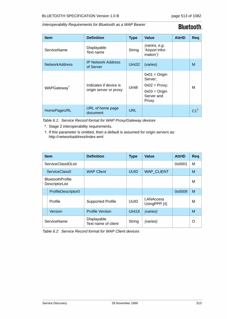
BLUETOOTH SPECIFICATION Version 1.0 B page 513 of 1082
Interoperability Requirements for Bluetooth as a WAP Bearer
ServiceNameDisplayable Text name
String(varies, e.g. ’Airport infor-mation’)
NetworkAddressIP Network Address of Server
Uint32 (varies) M
WAPGateway* Indicates if device is origin server or proxy
Uint8
0x01 = Origin Server;
0x02 = Proxy;
0x03 = Origin Server and Proxy
M
HomePageURLURL of home page document
URL C1†
*. Stage 2 interoperability requirements.
†. If this parameter is omitted, then a default is assumed for origin servers as: http://networkaddress/index.wml
Item Definition Type Value AttrID Req
ServiceClassIDList 0x0001 M
ServiceClass0 WAP Client UUID WAP_CLIENT M
BluetoothProfileDescriptorList
M
ProfileDescriptor0 0x0009 M
Profile Supported Profile UUIDLANAccessUsingPPP [4]
M
Version Profile Version Uint16 (varies) M
ServiceNameDisplayable Text name of client
String (varies) O
Table 6.2: Service Record format for WAP Client devices
Item Definition Type Value AttrID Req
Table 6.1: Service Record format for WAP Proxy/Gateway devices
Service Discovery 29 November 1999 513

BLUETOOTH SPECIFICATION Version 1.0 B page 514 of 1082
Interoperability Requirements for Bluetooth as a WAP Bearer
6.2 SDP PROTOCOL DATA UNITS
Table 6.3 shows the specified SDP PDUs (Protocol Data Units), which are required for WAP Interoperability.
6.3 SERVICE DISCOVERY PROCEDURE
In the simplest form, the signaling can be like this:
WAP service discovery procedures are symmetrical. Each device must be able to handle all of the PDUs without regard for the current device role. A minimal implementation must return the service name string.
PDUNo. SDP PDU
Ability to Send Ability to Retrieve
WAPClient
WAPProxy
WAPClient
WAPProxy
1 SdpErrorResponse M M M M
2 SdpServiceSearchAttributeRequest M O M M
3 SdpServiceSearchAttributeResponse M M M M
Table 6.3: SDP PDU:s
WAP Client or Proxy WAP Client or Proxy
SdpServiceSearchAttributeRequest
=======================>
SdpServiceSearchAttributeResponse
<=======================
514 29 November 1999 Service Discovery

BLUETOOTH SPECIFICATION Version 1.0 B page 515 of 1082
Interoperability Requirements for Bluetooth as a WAP Bearer
7 REFERENCES
[1] TS 101 369 (GSM 07.10) version 6.2.0
[2] Simpson, W., Editor, "The Point-to-Point Protocol (PPP)", STD 50, RFC 1661, Daydreamer, July 1994.
[3] Simpson, W., Editor, "PPP in HDLC Framing", STD 51, RFC 1662, Day-dreamer, July 1994.
[4] See Appendix VIII, “Bluetooth Assigned Numbers” on page 1009
[5] Wireless Application Protocol Forum, "Wireless Application Protocol", version 1.0, 1998
[6] Bluetooth Special Interest Group, "Bluetooth LAN Access Profile using PPP"
[7] Wireless Application Protocol Forum, "WAP Conformance", Draft version 27 May 1998
References 29 November 1999 515

516 29 November 1999 References
BLUETOOTH SPECIFICATION Version 1.0 B page 516 of 1082
Interoperability Requirements for Bluetooth as a WAP Bearer

Part H:1
HOST CONTROLLER INTERFACE FUNCTIONAL SPECIFICATION
This document describes the functional speci-fication for the Host Controller Interface (HCI). The HCI provides a command interface to the baseband controller and link manager, and access to hardware status and control regis-ters. This interface provides a uniform method of accessing the Bluetooth baseband capabili-ties.

BLUETOOTH SPECIFICATION Version 1.0 B page 518 of 1082
Host Controller Interface Functional Specification
518 29 November 1999

BLUETOOTH SPECIFICATION Version 1.0 B page 519 of 1082
Host Controller Interface Functional Specification
CONTENTS
1 Introduction ......................................................................................5241.1 Lower Layers of the Bluetooth Software Stack ........................5241.2 Bluetooth Hardware Block Diagram.........................................525
1.2.1 Link Controller .............................................................526
1.2.2 CPU Core ....................................................................526
1.3 Possible Physical Bus Architectures........................................5271.3.1 USB HCI Architecture..................................................527
1.3.2 PC Card HCI Architecture ...........................................527
2 Overview of Host Controller Transport Layer................................528
3 HCI Flow Control ..............................................................................529
4 HCI Commands.................................................................................5314.1 Introduction ..............................................................................5314.2 Terminology..............................................................................5314.3 Data and Parameter Formats...................................................5324.4 Exchange of HCI-Specific Information .....................................532
4.4.1 HCI Command Packet.................................................532
4.4.2 HCI Event Packet ........................................................535
4.4.3 HCI Data Packets........................................................536
4.5 Link Control Commands...........................................................5404.5.1 Inquiry..........................................................................542
4.5.2 Inquiry_Cancel ............................................................544
4.5.3 Periodic_Inquiry_Mode................................................545
4.5.4 Exit_Periodic_Inquiry_Mode........................................548
4.5.5 Create_Connection .....................................................549
4.5.6 Disconnect...................................................................552
4.5.7 Add_SCO_Connection ................................................553
4.5.8 Accept_Connection_Request......................................555
4.5.9 Reject_Connection_Request.......................................557
4.5.10 Link_Key_Request_Reply ...........................................558
4.5.11 Link_Key_Request_Negative_Reply...........................560
4.5.12 PIN_Code_Request_Reply .........................................561
4.5.13 PIN_Code_Request_Negative_Reply .........................563
4.5.14 Change_Connection_Packet_Type.............................564
4.5.15 Authentication_Requested ..........................................567
4.5.16 Set_Connection_Encryption........................................568
4.5.17 Change_Connection_Link_Key...................................569
4.5.18 Master_Link_Key.........................................................570
29 November 1999 519

BLUETOOTH SPECIFICATION Version 1.0 B page 520 of 1082
Host Controller Interface Functional Specification
4.5.19 Remote_Name_Request.............................................571
4.5.20 Read_Remote_Supported_Features ..........................573
4.5.21 Read_Remote_Version_Information...........................574
4.5.22 Read_Clock_Offset .....................................................575
4.6 Link Policy Commands ............................................................5764.6.1 Hold_Mode..................................................................578
4.6.2 Sniff_Mode ..................................................................580
4.6.3 Exit_Sniff_Mode ..........................................................582
4.6.4 Park_Mode..................................................................583
4.6.5 Exit_Park_Mode..........................................................585
4.6.6 QoS_Setup .................................................................586
4.6.7 Role_Discovery...........................................................588
4.6.8 Switch_Role ................................................................589
4.6.9 Read_Link_Policy_Settings ........................................590
4.6.10 Write_Link_Policy_Settings.........................................592
4.7 Host Controller & Baseband Commands.................................5944.7.1 Set_Event_Mask.........................................................600
4.7.2 Reset...........................................................................602
4.7.3 Set_Event_Filter .........................................................603
4.7.4 Flush ...........................................................................609
4.7.5 Read_PIN_Type.......................................................... 611
4.7.6 Write_PIN_Type ..........................................................612
4.7.7 Create_New_Unit_Key................................................613
4.7.8 Read_Stored_Link_Key ..............................................614
4.7.9 Write_Stored_Link_Key ..............................................616
4.7.10 Delete_Stored_Link_Key ............................................618
4.7.11 Change_Local_Name .................................................620
4.7.12 Read_Local_Name .....................................................621
4.7.13 Read_Connection_Accept_Timeout ...........................622
4.7.14 Write_Connection_Accept_Timeout............................623
4.7.15 Read_Page_Timeout ..................................................624
4.7.16 Write_Page_Timeout...................................................625
4.7.17 Read_Scan_Enable ....................................................626
4.7.18 Write_Scan_Enable ....................................................627
4.7.19 Read_Page_Scan_Activity..........................................628
4.7.20 Write_Page_Scan_Activity..........................................630
4.7.21 Read_Inquiry_Scan_Activity .......................................632
4.7.22 Write_Inquiry_Scan_Activity .......................................634
520 29 November 1999
BLUETOOTH SPECIFICATION Version 1.0 B page 521 of 1082
Host Controller Interface Functional Specification
4.7.23 Read_Authentication_Enable......................................636
4.7.24 Write_Authentication_Enable ......................................637
4.7.25 Read_Encryption_Mode..............................................638
4.7.26 Write_Encryption_Mode ..............................................639
4.7.27 Read_Class_of_Device...............................................641
4.7.28 Write_Class_of_Device ...............................................642
4.7.29 Read_Voice_Setting....................................................643
4.7.30 Write_Voice_Setting ....................................................645
4.7.31 Read_Automatic_Flush_Timeout ................................647
4.7.32 Write_Automatic_Flush_Timeout ................................649
4.7.33 Read_Num_Broadcast_Retransmissions ...................651
4.7.34 Write_Num_Broadcast_Retransmissions....................652
4.7.35 Read_Hold_Mode_Activity ..........................................653
4.7.36 Write_Hold_Mode_Activity ..........................................655
4.7.37 Read_Transmit_Power_Level .....................................656
4.7.38 Read_SCO_Flow_Control_Enable..............................658
4.7.39 Write_SCO_Flow_Control_Enable..............................659
4.7.40 Set_Host_Controller_To_Host_Flow_Control..............660
4.7.41 Host_Buffer_Size ........................................................661
4.7.42 Host_Number_Of_Completed_Packets ......................663
4.7.43 Read_Link_Supervision_Timeout ...............................665
4.7.44 Write Link_Supervision_Timeout.................................667
4.7.45 Read_Number_Of_Supported_IAC.............................669
4.7.46 Read_Current_IAC_LAP.............................................670
4.7.47 Write_Current_IAC_LAP .............................................671
4.7.48 Read_Page_Scan_Period_Mode................................673
4.7.49 Write_Page_Scan_Period_Mode ................................675
4.7.50 Read_Page_Scan_Mode ............................................676
4.7.51 Write_Page_Scan_Mode ............................................677
4.8 Informational Parameters.........................................................6784.8.1 Read_Local_Version_Information ...............................679
4.8.2 Read_Local_Supported_Features ..............................681
4.8.3 Read_Buffer_Size .......................................................682
4.8.4 Read_Country_Code...................................................684
4.8.5 Read_BD_ADDR.........................................................685
4.9 Status Parameters ...................................................................6864.9.1 Read_Failed_Contact_Counter...................................687
4.9.2 Reset_Failed_Contact_Counter ..................................689
29 November 1999 521

BLUETOOTH SPECIFICATION Version 1.0 B page 522 of 1082
Host Controller Interface Functional Specification
4.9.3 Get_Link_Quality ........................................................691
4.9.4 Read_RSSI .................................................................693
4.10 Testing Commands ..................................................................6954.10.1 Read_Loopback_Mode...............................................696
4.10.2 Write_Loopback_Mode ...............................................699
4.10.3 Enable_Device_Under_Test_Mode.............................702
5 Events ...............................................................................................7035.1 Event........................................................................................7035.2 Possible Events .......................................................................706
5.2.1 Inquiry Complete event ...............................................706
5.2.2 Inquiry Result event ....................................................707
5.2.3 Connection Complete event........................................709
5.2.4 Connection Request event.......................................... 711
5.2.5 Disconnection Complete event ...................................712
5.2.6 Authentication Complete event ...................................713
5.2.7 Remote Name Request Complete event ....................714
5.2.8 Encryption Change event............................................715
5.2.9 Change Connection Link Key Complete event ...........716
5.2.10 Master Link Key Complete event ................................717
5.2.11 Read Remote Supported Features Complete event ...718
5.2.12 Read Remote Version Information Complete event....719
5.2.13 QoS Setup Complete event ........................................721
5.2.14 Command Complete event .........................................723
5.2.15 Command Status event...............................................724
5.2.16 Hardware Error event..................................................725
5.2.17 Flush Occurred event..................................................726
5.2.18 Role Change event .....................................................727
5.2.19 Number Of Completed Packets event.........................728
5.2.20 Mode Change event....................................................730
5.2.21 Return Link Keys event...............................................732
5.2.22 PIN Code Request event ............................................733
5.2.23 Link Key Request event ..............................................734
5.2.24 Link Key Notification event..........................................735
5.2.25 Loopback Command event .........................................736
5.2.26 Data Buffer Overflow event .........................................737
5.2.27 Max Slots Change event .............................................738
5.2.28 Read Clock Offset Complete event.............................739
5.2.29 Connection Packet Type Changed event....................740
522 29 November 1999
BLUETOOTH SPECIFICATION Version 1.0 B page 523 of 1082
Host Controller Interface Functional Specification
5.2.30 QoS Violation event.....................................................742
5.2.31 Page Scan Mode Change event .................................743
5.2.32 Page Scan Repetition Mode Change event ................744
6 List of Error Codes...........................................................................7456.1 List of Error Codes ...................................................................7456.2 HCI Error Code Usage Descriptions ........................................7476.3 Unknown HCI Command (0x01) ..............................................7476.4 No Connection (0x02) ..............................................................7486.5 Hardware Failure (0x03) ..........................................................7486.6 Page Timeout (0x04)................................................................7486.7 Authentication Failed (0x05) ....................................................7486.8 Key Missing (0x06)...................................................................7486.9 Memory Full (0x07) ..................................................................7496.10 Connection Timeout (0x08)......................................................7496.11 Max Number Of Connections (0x09)........................................7496.12 Max Number Of SCO Connections To A Device (0x0A) ..........7506.13 ACL Connection Already Exists (0x0B)....................................7506.14 Command Disallowed (0x0C) ..................................................7506.15 Host Rejected due to … (0x0D-0x0F)......................................7506.16 Host Timeout (0x10).................................................................7516.17 Unsupported Feature or Parameter Value (0x11) ....................7516.18 Invalid HCI Command Parameters (0x12) ...............................7516.19 Other End Terminated Connection: … (0x13-0x15) .................7526.20 Connection Terminated By Local Host (0x16)..........................7526.21 Repeated Attempts (0x17) .......................................................7526.22 Pairing Not Allowed (0x18).......................................................7536.23 Unsupported Remote Feature (0x1A)......................................7536.24 Unspecified error (0x1F) ..........................................................7536.25 Unsupported LMP Parameter Value (0x20) .............................7536.26 Role Change Not Allowed (0x21).............................................7536.27 LMP Response Timeout (0x22) ...............................................7546.28 LMP Error Transaction Collision (0X23)...................................7546.29 LMP PDU Not Allowed (0X24) .................................................754
7 List of Acronyms and Abbreviations..............................................755
8 List of Figures...................................................................................756
9 List of Tables ....................................................................................757
29 November 1999 523

BLUETOOTH SPECIFICATION Version 1.0 B page 524 of 1082
Host Controller Interface Functional Specification
1 INTRODUCTION
This document describes the functional specifications for the Host Controller Interface (HCI). The HCI provides a uniform interface method of accessing the Bluetooth hardware capabilities. The next two sections provide a brief overview of the lower layers of the Bluetooth software stack and of the Bluetooth hard-ware. Section 2, provides an overview of the Lower HCI Device Driver Interface on the host device. Section 3, describes the flow control used between the Host and the Host Controller. Section 4, describes each of the HCI Commands in details, identifies parameters for each of the commands, and lists events associated with each command.
1.1 LOWER LAYERS OF THE BLUETOOTH SOFTWARE STACK
Figure 1.1: Overview of the Lower Software Layers
Figure 1.1, provides an overview of the lower software layers. The HCI firm-ware implements the HCI Commands for the Bluetooth hardware by accessing baseband commands link manager commands, hardware status registers, control registers, and event registers.
Physical Bus
Hardware
Bluetooth Host
Bluetooth Hardware
Other Higher Layer Driver
HCI Driver
Physical Bus (USB,PC Card,Other) Driver
Physical Bus (USB,PC Card, Other) Firmware
HCI Firmware
Baseband Controller
Software
FirmwareHarware
Link ManagerFirmware
Hardware
524 29 November 1999 Introduction

BLUETOOTH SPECIFICATION Version 1.0 B page 525 of 1082
Host Controller Interface Functional Specification
Several layers may exist between the HCI driver on the host system and the HCI firmware in the Bluetooth hardware. These intermediate layers, the Host Controller Transport Layer, provide the ability to transfer data without intimate knowledge of the data.
Figure 1.2: End to End Overview of Lower Software Layers to Transfer Data
Figure 1.2, illustrates the path of a data transfer from one device to another. The HCI driver on the Host exchanges data and commands with the HCI firm-ware on the Bluetooth hardware. The Host Control Transport Layer (i.e. physi-cal bus) driver provides both HCI layers with the ability to exchange information with each other.
The Host will receive asynchronous notifications of HCI events independent of which Host Controller Transport Layer is used. HCI events are used for notify-ing the Host when something occurs. When the Host discovers that an event has occurred it will then parse the received event packet to determine which event occurred.
1.2 BLUETOOTH HARDWARE BLOCK DIAGRAM
A general overview of the Bluetooth hardware is outlined in Figure 1.3 on page 526. It consists of an analog part – the Bluetooth radio, and a digital part – the Host Controller. The Host Controller has a hardware digital signal processing part –the Link Controller (LC), a CPU core, and it interfaces to the host environ-ment. The hardware and software parts of the Host Controller are described below.
Physical Bus (USB,PCCard, Other) Firmware
Bluetooth Hardware
HCI Firmware
Baseband Controller
Link ManagerFirmware
Physical BusHardware
HCI
Physical Bus (USB, PCCard, Other) Firmware
Bluetooth Hardware
HCI Firmware
Baseband Controller
Link ManagerFirmware
HCI
Software
FirmwareHardware
Host 1 Host 2
Physical BusHardware
Bluetooth Host
Other Higher Layer Driver
HCI Driver
Physical Bus Driver (USB,PC Card,Other) Driver
Bluetooth Host
Other Higher Layer Driver
HCI Driver
Physical Bus Driver (USB,PC Card,Other) Driver
Wireless
User Data
Physical Physical
Introduction 29 November 1999 525

BLUETOOTH SPECIFICATION Version 1.0 B page 526 of 1082
Host Controller Interface Functional Specification
Figure 1.3: Bluetooth Hardware Architecture Overview.
1.2.1 Link Controller
The Link Controller (LC) consists of hardware and software parts that perform Bluetooth baseband processing, and physical layer protocols such as ARQ-protocol and FEC coding.
The functions performed by the Link Controller include:
• Transfer types with selected Quality-of-Service (QoS) parameters
• Asynchronous transfers with guaranteed delivery using hardware fast Auto-matic Repeat reQuest (fARQ). Frames can be flushed from the retransmis-sion buffer, for use with isochronous data
• Synchronous transfers
• Audio coding. A power-efficient hardware implementation of a robust 64 Kbits/s Continuous Variable Slope Delta (CVSD) coding, as well as 64 Kbits/s log-PCM
• Encryption
1.2.2 CPU Core
The CPU core will allow the Bluetooth module to handle Inquiries and filter Page requests without involving the host device. The Host Controller can be programmed to answer certain Page messages and authenticate remote links.
The Link Manager (LM) software runs on the CPU Core. The LM discovers other remote LMs and communicates with them via the Link Manager Protocol (LMP) to perform its service provider role using the services of the underlying Link Controller (LC). For details see “Link Manager Protocol” on page 185
�������Bluetooth Host Controller
Link ManagerHost Interface
%OXHWRRWK�5DGLR/LQN�EDVHEDQG&RQWUROOHU��/&�
&38
FRUH
RadioInterface
([WHUQDO
LQWHUIDFHV
526 29 November 1999 Introduction
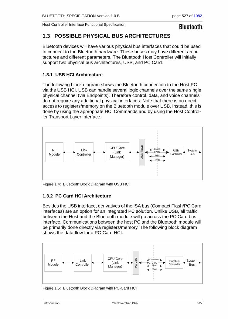
BLUETOOTH SPECIFICATION Version 1.0 B page 527 of 1082
Host Controller Interface Functional Specification
1.3 POSSIBLE PHYSICAL BUS ARCHITECTURES
Bluetooth devices will have various physical bus interfaces that could be used to connect to the Bluetooth hardware. These buses may have different archi-tectures and different parameters. The Bluetooth Host Controller will initially support two physical bus architectures, USB, and PC Card.
1.3.1 USB HCI Architecture
The following block diagram shows the Bluetooth connection to the Host PC via the USB HCI. USB can handle several logic channels over the same single physical channel (via Endpoints). Therefore control, data, and voice channels do not require any additional physical interfaces. Note that there is no direct access to registers/memory on the Bluetooth module over USB. Instead, this is done by using the appropriate HCI Commands and by using the Host Control-ler Transport Layer interface.
Figure 1.4: Bluetooth Block Diagram with USB HCI
1.3.2 PC Card HCI Architecture
Besides the USB interface, derivatives of the ISA bus (Compact Flash/PC Card interfaces) are an option for an integrated PC solution. Unlike USB, all traffic between the Host and the Bluetooth module will go across the PC Card bus interface. Communications between the host PC and the Bluetooth module will be primarily done directly via registers/memory. The following block diagram shows the data flow for a PC-Card HCI.
Figure 1.5: Bluetooth Block Diagram with PC-Card HCI
RFModule
LinkController
CPU Core(Link
Manager) US
B S
lave
USBController
USBControl
Data
Voice
SystemBus
RFModule
LinkController
CPU Core(Link
Manager) PC
-Car
d
CardbusController
PC-CardCommands
Data
Voice
SystemBus
Introduction 29 November 1999 527

BLUETOOTH SPECIFICATION Version 1.0 B page 528 of 1082
Host Controller Interface Functional Specification
2 OVERVIEW OF HOST CONTROLLER TRANSPORT LAYER
The host driver stack has a transport layer between the Host Controller driver and the Host Controller. On a laptop, this transport layer might be PC Card or Universal Serial Bus (USB).
The main goal of this transport layer is transparency. The Host Controller driver (which talks to the Host Controller) should not care whether it is running over USB or a PC Card. Nor should USB or PC Card require any visibility into the data that the Host Controller driver passes to the Host Controller. This allows the interface (HCI) or the Host Controller to be upgraded without affecting the transport layer.
The Host Controller Transport Layer is described in separate documents for each physical media.
- “HCI USB Transport Layer” on page 759.- “HCI RS232 Transport Layer” on page 775.- “HCI UART Transport Layer” on page 795.
528 29 November 1999 Overview of Host Controller Transport Layer

BLUETOOTH SPECIFICATION Version 1.0 B page 529 of 1082
Host Controller Interface Functional Specification
3 HCI FLOW CONTROL
Flow control is used in the direction from the Host to the Host Controller to avoid filling up the Host Controller data buffers with ACL data destined for a remote device (connection handle) that is not responding. It is the Host that manages the data buffers of the Host Controller.
On Initialization, the Host will issue the Read_Buffer_Size command. Two of the return parameters of this command determine the maximum size of HCI ACL and SCO Data Packets (excluding header) sent from the Host to the Host Controller. There are also two additional return parameters that specify the total number of HCI ACL and SCO Data Packets that the Host Controller can have waiting for transmission in its buffers. When there is at least one connection to another device, or when in local loopback mode, the Host Controller uses the Number Of Com-pleted Packets event to control the flow of data from the Host. This event contains a list of connection handles and a corresponding number of HCI Data Packets that have been completed (transmitted, flushed, or looped back to the Host) since the previous time the event was returned (or since the connection was established, if the event has not been returned before for a particular connection handle). Based on the information returned in this event, and the return parameters of the Read_Buffer_Size command that specify the total number of HCI ACL and SCO Data Packets that can be stored in the Host Controller, the Host can decide for which Connection Handles the following HCI Data Packets should be sent. After every time it has sent an HCI Data Packet, the Host must assume that the free buffer space for the corresponding link type (ACL or SCO) in the Host Controller has decreased by one HCI Data Packet. When the Host receives a new Number Of Completed Packets event, the Host gets information about how much the buffer usage has decreased since the previous time the event was returned. It can then calculate the actual current buffer usage. While the Host Controller has HCI data packets in its buffer, it must keep sending the Number Of Completed Packets event to the Host at least periodically, until it finally reports that all the pending ACL Data Packets have been transmitted or flushed. The rate with which this event is sent is manufacturer specific. Note that Number Of Completed Packets events will not report on SCO connection handles if SCO Flow Control is disabled. (See Read/Write_SCO_Flow_Control_Enable on page 658 and page 659.)
Note that for each individual Connection Handle, the data must be sent to the Host Controller in HCI Data Packets in the order in which it was created in the Host. The Host Controller must also transmit data on the air that is received from the Host for a given Connection Handle in the same order as it is received from the Host. Furthermore, data that is received on the air from another device must, for the corresponding Connection Handle, be sent in HCI Data Packets to the Host in the same order as it is received. This means that the scheduling is made on a Connection Handle basis. For each individual Con-nection Handle, the order of the data must not be changed from the order in which the data has been created.
HCI Flow Control 29 November 1999 529

BLUETOOTH SPECIFICATION Version 1.0 B page 530 of 1082
Host Controller Interface Functional Specification
In certain cases, flow control may also be necessary in the direction from the Host Controller to the Host. There is therefore a command –Set_Host_Controller_To_Host_Flow_Control – to turn flow control on or off in that direction. If turned on, it works in exactly the same way as described above. On initialization, the Host uses the Host_Buffer_Size command to notify the Host Controller about the maximum size of HCI ACL and SCO Data Pack-ets sent from the Host Controller to the Host. The command also contains two additional command parameters to notify the Host Controller about the total number of ACL and SCO Data Packets that can be stored in the data buffers of the Host. The Host then uses the Host_Number_Of_Completed_Packets com-mand in exactly the same way as the Host Controller uses the Number Of Completed Packets event (as was previously described in this section). The Host_Number_Of_Completed_Packets command is a special command for which no command flow control is used, and which can be sent anytime there is a connection or when in local loopback mode. This makes it possible for the flow control to work in exactly the same way in both directions, and the flow of normal commands will not be disturbed.
When the Host receives a Disconnection Complete event, the Host can assume that all HCI Data Packets that have been sent to the Host Controller for the returned Connection_Handle have been flushed, and that the corre-sponding data buffers have been freed. The Host Controller does not have to notify the Host about this in a Number Of Completed Packets event. If flow con-trol is also enabled in the direction from the Host Controller to the Host, the Host Controller can after it has sent a Disconnection_Complete event assume that the Host will flush its data buffers for the sent Connection_Handle when it receives the Disconnection_Complete event. The Host does not have to notify the Host Controller about this in a Host_Number_Of_Completed_Packets com-mand.
530 29 November 1999 HCI Flow Control

BLUETOOTH SPECIFICATION Version 1.0 B page 531 of 1082
Host Controller Interface Functional Specification
4 HCI COMMANDS
4.1 INTRODUCTION
The HCI provides a uniform command method of accessing the Bluetooth hard-ware capabilities. The HCI Link commands provide the Host with the ability to control the link layer connections to other Bluetooth devices. These commands typically involve the Link Manager (LM) to exchange LMP commands with remote Bluetooth devices. For details see “Link Manager Protocol” on page 185.
The HCI Policy commands are used to affect the behavior of the local and remote LM. These Policy commands provide the Host with methods of influ-encing how the LM manages the piconet. The Host Controller & Baseband, Informational, and Status commands provide the Host access to various regis-ters in the Host Controller.
HCI commands may take different amounts of time to be completed. There-fore, the results of commands will be reported back to the Host in the form of an event. For example, for most HCI commands the Host Controller will gener-ate the Command Complete event when a command is completed. This event contains the return parameters for the completed HCI command. To detect errors on the HCI-Transport Layer a response timeout needs to be defined between the Host Controller receiving a command and sending a response to the command (e.g. a Command Complete or Command Status event). Since the maximum response timeout is strongly dependent on the HCI-Transport Layer used, it is recommended to use a default value of one second for this timer. This amount of time is also dependent on the number of commands unprocessed in the command queue.
4.2 TERMINOLOGY
Baseband Packet: The smallest unit of data that is transmitted by one device to another, as defined by the “Baseband Specification” on page 33.
Packet: A higher-level protocol message than the baseband packet, currently only L2CAP (see “Logical Link Control and Adaptation Protocol Specification” on page 245) is defined, but additional packet types may be defined later.
Connection Handle: A connection handle is a 12-bit identifier which is used to uniquely address a data/voice connection from one Bluetooth device to another. The connection handles can be visualized as identifying a unique data pipe that connects two Bluetooth devices. The connection handle is maintained for the lifetime of a connection, including when a device enters Park, Sniff, or Hold mode. The Connection Handle value has local scope between Host and Host Controller. There can be multiple connection handles for any given pair of Bluetooth devices but only one ACL connection.
Event: A mechanism that the HCI uses to notify the Host for command comple-tion, link layer status changes, etc.
HCI Commands 29 November 1999 531

BLUETOOTH SPECIFICATION Version 1.0 B page 532 of 1082
Host Controller Interface Functional Specification
4.3 DATA AND PARAMETER FORMATS• All values are in Binary and Hexadecimal Little Endian formats unless other-
wise noted
• In addition, all parameters which can have negative values must use 2’s complement when specifying values
• Arrayed parameters are specified using the following notation: Parame-terA[i]. If more than one set of arrayed parameters are specified (e.g. ParameterA[i], ParameterB[i]), then the order of the parameters are as fol-lows: ParameterA[0], ParameterB[0], ParameterA[1], ParameterB[1], ParameterA[2], ParameterB[2], … ParameterA[n], ParameterB[n]
• Unless noted otherwise, all parameter values are sent and received in Little Endian format (i.e. for multi-byte parameters the rightmost (Least Significa-tion Byte) is transmitted first)
• All command and event parameters that are not-arrayed and all elements in an arrayed parameter have fixed sizes (an integer number of bytes). The parameters and the size of each not arrayed parameter (or of each element in an arrayed parameter) contained in a command or an event is specified for each command or event. The number of elements in an arrayed parame-ter is not fixed.
4.4 EXCHANGE OF HCI-SPECIFIC INFORMATION
The Host Controller Transport Layer provides transparent exchange of HCI-specific information. These transporting mechanisms provide the ability for the Host to send HCI commands, ACL data, and SCO data to the Host Controller. These transport mechanisms also provide the ability for the Host to receive HCI events, ACL data, and SCO data from the Host Controller.
Since the Host Controller Transport Layer provides transparent exchange of HCI-specific information, the HCI specification specifies the format of the com-mands, events, and data exchange between the Host and the Host Controller. The next sections specify the HCI packet formats.
4.4.1 HCI Command Packet
The HCI Command Packet is used to send commands to the Host Controller from the Host. The format of the HCI Command Packet is shown in Figure 4.1, and the definition of each field is explained below. When the Host Controller completes most of the commands, a Command Complete event is sent to the Host. Some commands do not receive a Command Complete event when they have been completed. Instead, when the Host Controller receives one of these commands the Host Controller sends a Command Status event back to the Host when it has begun to execute the command. Later on, when the actions associated with the command have finished, an event that is associated with the sent command will be sent by the Host Controller to the Host. However, if the command does not begin to execute (there may be a parameter error or the
532 29 November 1999 HCI Commands

BLUETOOTH SPECIFICATION Version 1.0 B page 533 of 1082
Host Controller Interface Functional Specification
command may currently not be allowed), the event associated with the sent command will not be returned. The Command Status event will, in this case, return the appropriate error code in the Status parameter. On initial power-on, and after a reset, the Host can send a maximum of one outstanding HCI Com-mand Packet until a Command Complete or Command Status event has been received. If an error occurs for a command for which a Command Complete event is returned, the Return_Parameters field may not contain all the return parameters specified for the command. The Status parameter, which explains the error reason and which is the first return parameter, will always be returned. If there is a Connection_Handle parameter or a BD_ADDR parameter right after the Status parameter, this parameter will also be returned so that the Host can identify to which instance of a command the Command Complete event belongs. In this case, the Connection_Handle or BD_ADDR parameter will have exactly the same value as that in the corresponding command parameter. It is implementation specific whether more parameters will be returned in case of an error.
Note: The BD_ADDR return parameter of the command Read_BD_ADDR is not used to identify to which instance of the Read_BD_ADDR command the Command Complete event belongs. It is therefore not mandatory for the Host Controller to return this parameter in case of an error.
If an error occurs for a command for which no Command Complete event is returned, all parameters returned with the event associated with this command may not be valid. The Host must take care as to which parameters may have valid values depending on the value of the Status parameter of the Complete event associated with the given command. The Command Complete and Com-mand Status events contain a parameter called Num_HCI_Command_Packets, which indicates the number of HCI Command Packets the Host is currently allowed to send to the Host Controller. The Host Controller may buffer one or more HCI command packets, but the Host Con-troller must start performing the commands in the order in which they are received. The Host Controller can start performing a command before it com-pletes previous commands. Therefore, the commands do not always complete in the order they are started. The Host Controller must be able to accept HCI Command Packets with up to 255 bytes of data excluding the HCI Command Packet header.
Each command is assigned a 2 byte Opcode used to uniquely identify different types of commands. The Opcode parameter is divided into two fields, called the OpCode Group Field (OGF) and OpCode Command Field (OCF). The OGF occupies the upper 6 bits of the Opcode, while the OCF occupies the remaining 10 bits. The OGF of 0x3F is reserved for vendor-specific debug commands. The OGF of 0x3E is reserved for Bluetooth Logo Testing. The organization of the Opcodes allows additional information to be inferred without fully decoding the entire Opcode.
HCI Commands 29 November 1999 533

BLUETOOTH SPECIFICATION Version 1.0 B page 534 of 1082
Host Controller Interface Functional Specification
Note: the OGF composed of all ‘ones’ has been reserved for vendor-specific debug commands. These commands are vendor-specific and are used during manufacturing, for a possible method for updating firmware, and for debugging.
Figure 4.1: HCI Command Packet
Op_Code: Size: 2 Bytes
Parameter_Total_Length: Size: 1 Byte
Parameter 0 - N: Size: Parameter Total Length
Value Parameter Description
0xXXXX OGFRange (6 bits): 0x00-0x3F (0x3E reserved for Bluetooth logo testing and 0x3F reserved for vendor-specific debug commands)
OCF Range (10 bits): 0x0000-0x03FF
Value Parameter Description
0xXX Lengths of all of the parameters contained in this packet measured in bytes. (N.B.: total length of parameters, not number of parameters)
Value Parameter Description
0xXX Each command has a specific number of parameters associated with it. These parameters and the size of each of the parameters are defined for each command. Each parameter is an integer number of bytes in size.
4 8 12 16 20 24 28 31
OGFOCFParameter Total
LengthParameter 0
Parameter 1 Parameter ...
Parameter N-1
OpCode
Parameter N
0
534 29 November 1999 HCI Commands
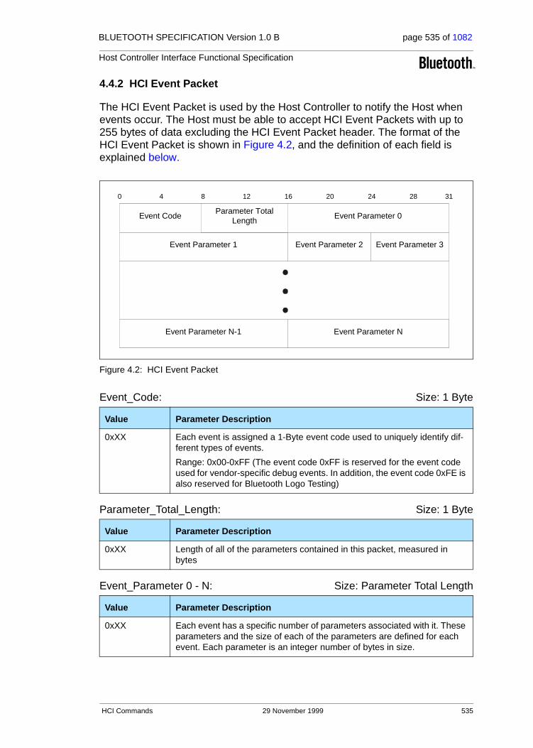
BLUETOOTH SPECIFICATION Version 1.0 B page 535 of 1082
Host Controller Interface Functional Specification
4.4.2 HCI Event Packet
The HCI Event Packet is used by the Host Controller to notify the Host when events occur. The Host must be able to accept HCI Event Packets with up to 255 bytes of data excluding the HCI Event Packet header. The format of the HCI Event Packet is shown in Figure 4.2, and the definition of each field is explained below.
Figure 4.2: HCI Event Packet
Event_Code: Size: 1 Byte
Parameter_Total_Length: Size: 1 Byte
Event_Parameter 0 - N: Size: Parameter Total Length
Value Parameter Description
0xXX Each event is assigned a 1-Byte event code used to uniquely identify dif-ferent types of events.
Range: 0x00-0xFF (The event code 0xFF is reserved for the event code used for vendor-specific debug events. In addition, the event code 0xFE is also reserved for Bluetooth Logo Testing)
Value Parameter Description
0xXX Length of all of the parameters contained in this packet, measured in bytes
Value Parameter Description
0xXX Each event has a specific number of parameters associated with it. These parameters and the size of each of the parameters are defined for each event. Each parameter is an integer number of bytes in size.
0 4 8 12 16 20 24 28 31
Event Code Event Parameter 0
Event Parameter 1
Parameter TotalLength
Event Parameter 3Event Parameter 2
Event Parameter N-1 Event Parameter N
HCI Commands 29 November 1999 535

BLUETOOTH SPECIFICATION Version 1.0 B page 536 of 1082
Host Controller Interface Functional Specification
4.4.3 HCI Data Packets
HCI Data Packets are used to exchange data between the Host and Host Con-troller. The data packets are defined for both ACL and SCO data types. The format of the HCI ACL Data Packet is shown in Figure 4.3, and the format of the SCO Data Packet is shown in Figure 4.4. The definition for each of the fields in the data packets is explained below.
Figure 4.3: HCI ACL Data Packet
Data
0 4 8 12 16 20 24 28 31
Connection Handle PBFlag
BCFlag
Data Total Length
536 29 November 1999 HCI Commands
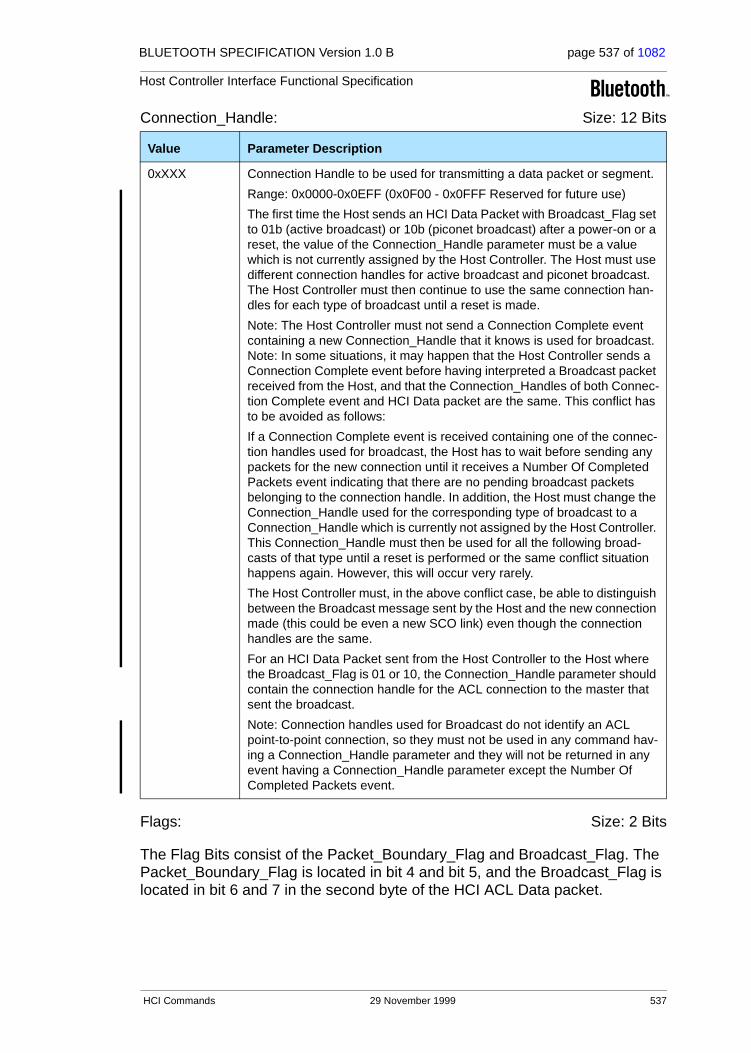
BLUETOOTH SPECIFICATION Version 1.0 B page 537 of 1082
Host Controller Interface Functional Specification
Connection_Handle: Size: 12 Bits
Flags: Size: 2 Bits
The Flag Bits consist of the Packet_Boundary_Flag and Broadcast_Flag. The Packet_Boundary_Flag is located in bit 4 and bit 5, and the Broadcast_Flag is located in bit 6 and 7 in the second byte of the HCI ACL Data packet.
Value Parameter Description
0xXXX Connection Handle to be used for transmitting a data packet or segment.
Range: 0x0000-0x0EFF (0x0F00 - 0x0FFF Reserved for future use)
The first time the Host sends an HCI Data Packet with Broadcast_Flag set to 01b (active broadcast) or 10b (piconet broadcast) after a power-on or a reset, the value of the Connection_Handle parameter must be a value which is not currently assigned by the Host Controller. The Host must use different connection handles for active broadcast and piconet broadcast. The Host Controller must then continue to use the same connection han-dles for each type of broadcast until a reset is made.
Note: The Host Controller must not send a Connection Complete event containing a new Connection_Handle that it knows is used for broadcast. Note: In some situations, it may happen that the Host Controller sends a Connection Complete event before having interpreted a Broadcast packet received from the Host, and that the Connection_Handles of both Connec-tion Complete event and HCI Data packet are the same. This conflict has to be avoided as follows:
If a Connection Complete event is received containing one of the connec-tion handles used for broadcast, the Host has to wait before sending any packets for the new connection until it receives a Number Of Completed Packets event indicating that there are no pending broadcast packets belonging to the connection handle. In addition, the Host must change the Connection_Handle used for the corresponding type of broadcast to a Connection_Handle which is currently not assigned by the Host Controller. This Connection_Handle must then be used for all the following broad-casts of that type until a reset is performed or the same conflict situation happens again. However, this will occur very rarely.
The Host Controller must, in the above conflict case, be able to distinguish between the Broadcast message sent by the Host and the new connection made (this could be even a new SCO link) even though the connection handles are the same.
For an HCI Data Packet sent from the Host Controller to the Host where the Broadcast_Flag is 01 or 10, the Connection_Handle parameter should contain the connection handle for the ACL connection to the master that sent the broadcast.
Note: Connection handles used for Broadcast do not identify an ACL point-to-point connection, so they must not be used in any command hav-ing a Connection_Handle parameter and they will not be returned in any event having a Connection_Handle parameter except the Number Of Completed Packets event.
HCI Commands 29 November 1999 537
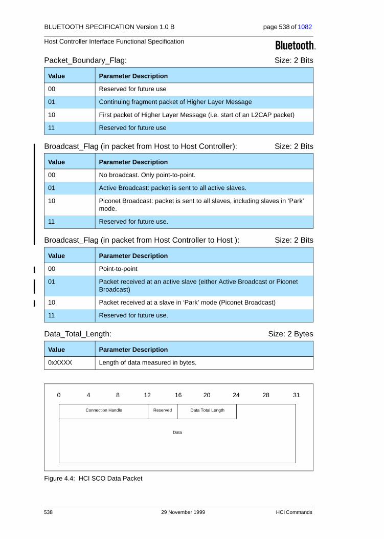
BLUETOOTH SPECIFICATION Version 1.0 B page 538 of 1082
Host Controller Interface Functional Specification
Packet_Boundary_Flag: Size: 2 Bits
Broadcast_Flag (in packet from Host to Host Controller): Size: 2 Bits
Broadcast_Flag (in packet from Host Controller to Host ): Size: 2 Bits
Data_Total_Length: Size: 2 Bytes
Figure 4.4: HCI SCO Data Packet
Value Parameter Description
00 Reserved for future use
01 Continuing fragment packet of Higher Layer Message
10 First packet of Higher Layer Message (i.e. start of an L2CAP packet)
11 Reserved for future use
Value Parameter Description
00 No broadcast. Only point-to-point.
01 Active Broadcast: packet is sent to all active slaves.
10 Piconet Broadcast: packet is sent to all slaves, including slaves in ‘Park’ mode.
11 Reserved for future use.
Value Parameter Description
00 Point-to-point
01 Packet received at an active slave (either Active Broadcast or Piconet Broadcast)
10 Packet received at a slave in ‘Park’ mode (Piconet Broadcast)
11 Reserved for future use.
Value Parameter Description
0xXXXX Length of data measured in bytes.
Data
0 4 8 12 16 20 24 28 31
Connection Handle Reserved Data Total Length
538 29 November 1999 HCI Commands

BLUETOOTH SPECIFICATION Version 1.0 B page 539 of 1082
Host Controller Interface Functional Specification
Connection_Handle: Size: 12 Bits
The Reserved Bits consist of four bits which are located from bit 4 to bit 7 in the second byte of the HCI SCO Data packet.
Reserved: Size: 4 Bits
Data_Total_Length: Size: 1 Byte
Value Parameter Description
0xXXX Connection handle to be used to for transmitting a SCO data packet or segment.
Range: 0x0000-0x0EFF (0x0F00- 0x0FFF Reserved for future use)
Value Parameter Description
XXXX Reserved for future use.
Value Parameter Description
0xXX Length of SCO data measured in bytes
HCI Commands 29 November 1999 539
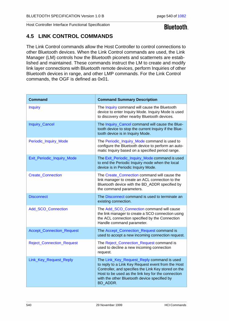
BLUETOOTH SPECIFICATION Version 1.0 B page 540 of 1082
Host Controller Interface Functional Specification
4.5 LINK CONTROL COMMANDS
The Link Control commands allow the Host Controller to control connections to other Bluetooth devices. When the Link Control commands are used, the Link Manager (LM) controls how the Bluetooth piconets and scatternets are estab-lished and maintained. These commands instruct the LM to create and modify link layer connections with Bluetooth remote devices, perform Inquiries of other Bluetooth devices in range, and other LMP commands. For the Link Control commands, the OGF is defined as 0x01.
Command Command Summary Description
Inquiry The Inquiry command will cause the Bluetooth device to enter Inquiry Mode. Inquiry Mode is used to discovery other nearby Bluetooth devices.
Inquiry_Cancel The Inquiry_Cancel command will cause the Blue-tooth device to stop the current Inquiry if the Blue-tooth device is in Inquiry Mode.
Periodic_Inquiry_Mode The Periodic_Inquiry_Mode command is used to configure the Bluetooth device to perform an auto-matic Inquiry based on a specified period range.
Exit_Periodic_Inquiry_Mode The Exit_Periodic_Inquiry_Mode command is used to end the Periodic Inquiry mode when the local device is in Periodic Inquiry Mode.
Create_Connection The Create_Connection command will cause the link manager to create an ACL connection to the Bluetooth device with the BD_ADDR specified by the command parameters.
Disconnect The Disconnect command is used to terminate an existing connection.
Add_SCO_Connection The Add_SCO_Connection command will cause the link manager to create a SCO connection using the ACL connection specified by the Connection Handle command parameter.
Accept_Connection_Request The Accept_Connection_Request command is used to accept a new incoming connection request.
Reject_Connection_Request The Reject_Connection_Request command is used to decline a new incoming connection request.
Link_Key_Request_Reply The Link_Key_Request_Reply command is used to reply to a Link Key Request event from the Host Controller, and specifies the Link Key stored on the Host to be used as the link key for the connection with the other Bluetooth device specified by BD_ADDR.
540 29 November 1999 HCI Commands

BLUETOOTH SPECIFICATION Version 1.0 B page 541 of 1082
Host Controller Interface Functional Specification
Command Command Summary Description
Link_Key_Request_Negative_Reply The Link_Key_Request_Negative_Reply com-mand is used to reply to a Link Key Request event from the Host Controller if the Host does not have a stored Link Key for the connection with the other Bluetooth Device specified by BD_ADDR.
PIN_Code_Request_Reply The PIN_Code_Request_Reply command is used to reply to a PIN Code Request event from the Host Controller and specifies the PIN code to use for a connection.
PIN_Code_Request_Negative_Reply The PIN_Code_Request_Negative_Reply com-mand is used to reply to a PIN Code Request event from the Host Controller when the Host cannot specify a PIN code to use for a connection.
Change_Connection_Packet_Type The Change_Connection_Packet_Type command is used to change which packet types can be used for a connection that is currently established.
Authentication_Requested The Authentication_Requested command is used to establish authentication between the two devices associated with the specified Connection Handle.
Set_Connection_Encryption The Set_Connection_Encryption command is used to enable and disable the link level encryption.
Change_Connection_Link_Key The Change_Connection_Link_Key command is used to force both devices of a connection associ-ated to the connection handle, to generate a new link key.
Master_Link_Key The Master_Link_Key command is used to force both devices of a connection associated to the con-nection handle to use the temporary link key of the Master device or the regular link keys.
Remote_Name_Request The Remote_Name_Request command is used to obtain the user-friendly name of another Bluetooth device.
Read_Remote_Supported_Features The Read_Remote_Supported_Features com-mand requests a list of the supported features of a remote device.
Read_Remote_Version_Information The Read_Remote_Version_Information command will read the values for the version information for the remote Bluetooth device.
Read_Clock_Offset The Read_Clock_Offset command allows the Host to read the clock offset of remote devices.
HCI Commands 29 November 1999 541
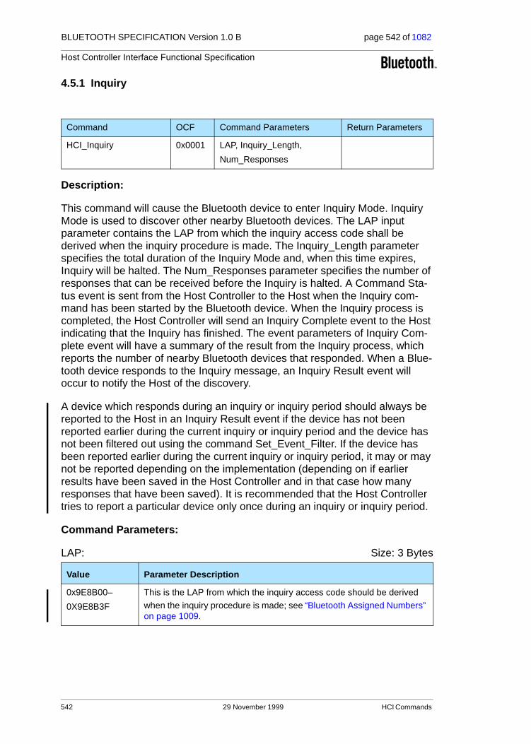
BLUETOOTH SPECIFICATION Version 1.0 B page 542 of 1082
Host Controller Interface Functional Specification
4.5.1 Inquiry
Description:
This command will cause the Bluetooth device to enter Inquiry Mode. Inquiry Mode is used to discover other nearby Bluetooth devices. The LAP input parameter contains the LAP from which the inquiry access code shall be derived when the inquiry procedure is made. The Inquiry_Length parameter specifies the total duration of the Inquiry Mode and, when this time expires, Inquiry will be halted. The Num_Responses parameter specifies the number of responses that can be received before the Inquiry is halted. A Command Sta-tus event is sent from the Host Controller to the Host when the Inquiry com-mand has been started by the Bluetooth device. When the Inquiry process is completed, the Host Controller will send an Inquiry Complete event to the Host indicating that the Inquiry has finished. The event parameters of Inquiry Com-plete event will have a summary of the result from the Inquiry process, which reports the number of nearby Bluetooth devices that responded. When a Blue-tooth device responds to the Inquiry message, an Inquiry Result event will occur to notify the Host of the discovery.
A device which responds during an inquiry or inquiry period should always be reported to the Host in an Inquiry Result event if the device has not been reported earlier during the current inquiry or inquiry period and the device has not been filtered out using the command Set_Event_Filter. If the device has been reported earlier during the current inquiry or inquiry period, it may or may not be reported depending on the implementation (depending on if earlier results have been saved in the Host Controller and in that case how many responses that have been saved). It is recommended that the Host Controller tries to report a particular device only once during an inquiry or inquiry period.
Command Parameters:
LAP: Size: 3 Bytes
Command OCF Command Parameters Return Parameters
HCI_Inquiry 0x0001 LAP, Inquiry_Length,
Num_Responses
Value Parameter Description
0x9E8B00–
0X9E8B3F
This is the LAP from which the inquiry access code should be derived
when the inquiry procedure is made; see “Bluetooth Assigned Numbers” on page 1009.
542 29 November 1999 HCI Commands
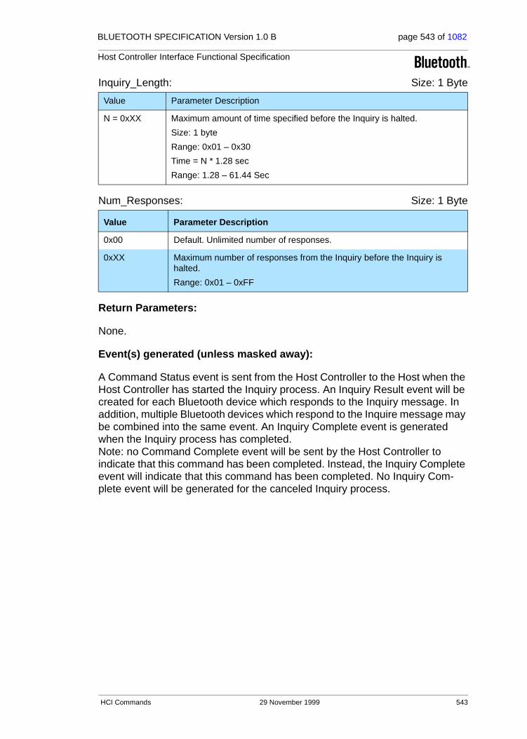
BLUETOOTH SPECIFICATION Version 1.0 B page 543 of 1082
Host Controller Interface Functional Specification
Inquiry_Length: Size: 1 Byte
Num_Responses: Size: 1 Byte
Return Parameters:
None.
Event(s) generated (unless masked away):
A Command Status event is sent from the Host Controller to the Host when the Host Controller has started the Inquiry process. An Inquiry Result event will be created for each Bluetooth device which responds to the Inquiry message. In addition, multiple Bluetooth devices which respond to the Inquire message may be combined into the same event. An Inquiry Complete event is generated when the Inquiry process has completed. Note: no Command Complete event will be sent by the Host Controller to indicate that this command has been completed. Instead, the Inquiry Complete event will indicate that this command has been completed. No Inquiry Com-plete event will be generated for the canceled Inquiry process.
Value Parameter Description
N = 0xXX Maximum amount of time specified before the Inquiry is halted.
Size: 1 byte
Range: 0x01 – 0x30
Time = N * 1.28 sec
Range: 1.28 – 61.44 Sec
Value Parameter Description
0x00 Default. Unlimited number of responses.
0xXX Maximum number of responses from the Inquiry before the Inquiry is halted.
Range: 0x01 – 0xFF
HCI Commands 29 November 1999 543

BLUETOOTH SPECIFICATION Version 1.0 B page 544 of 1082
Host Controller Interface Functional Specification
4.5.2 Inquiry_Cancel
Description:
This command will cause the Bluetooth device to stop the current Inquiry if the Bluetooth device is in Inquiry Mode. This command allows the Host to interrupt the Bluetooth device and request the Bluetooth device to perform a different task. The command should only be issued after the Inquiry command has been issued, a Command Status event has been received for the Inquiry command, and before the Inquiry Complete event occurs.
Return Parameters:
Status: Size: 1 Byte
Event(s) generated (unless masked away):
When the Inquiry Cancel command has completed, a Command Complete event will be generated. No Inquiry Complete event will be generated for the canceled Inquiry process.
Command OCF Command Parameters Return Parameters
HCI_Inquiry_Cancel 0x0002 Status
Value Parameter Description
0x00 Inquiry_Cancel command succeeded.
0x01-0xFF Inquiry_Cancel command failed. See Table 6.1 on page 745 for list of Error Codes.
544 29 November 1999 HCI Commands

BLUETOOTH SPECIFICATION Version 1.0 B page 545 of 1082
Host Controller Interface Functional Specification
4.5.3 Periodic_Inquiry_Mode
Description:
The Periodic_Inquiry_Mode command is used to configure the Bluetooth device to enter the Periodic Inquiry Mode that performs an automatic Inquiry. Max_Period_Length and Min_Period_Length define the time range between two consecutive inquiries, from the beginning of an inquiry until the start of the next inquiry. The Host Controller will use this range to determine a new random time between two consecutive inquiries for each Inquiry. The LAP input param-eter contains the LAP from which the inquiry access code shall be derived when the inquiry procedure is made. The Inquiry_Length parameter specifies the total duration of the InquiryMode and, when time expires, Inquiry will be halted. The Num_Responses parameter specifies the number of responses that can be received before the Inquiry is halted. This command is completed when the Inquiry process has been started by the Bluetooth device, and a Command Complete event is sent from the Host Controller to the Host. When each of the periodic Inquiry processes are completed, the Host Controller will send an Inquiry Complete event to the Host indicating that the latest periodic Inquiry process has finished. The event parameters of Inquiry Complete event will have a summary of the result from the previous Periodic Inquiry process, which reports the number of nearby Bluetooth devices that responded. When a Bluetooth device responds to the Inquiry message an Inquiry Result event will occur to notify the Host of the discovery. Note: Max_Period_Length > Min_Period_Length > Inquiry_Length
A device which responds during an inquiry or inquiry period should always be reported to the Host in an Inquiry Result event if the device has not been reported earlier during the current inquiry or inquiry period and the device has not been filtered out using the command Set_Event_Filter. If the device has been reported earlier during the current inquiry or inquiry period, it may or may not be reported depending on the implementation (depending on if earlier results have been saved in the Host Controller and in that case how many responses that have been saved). It is recommended that the Host Controller tries to report a particular device only once during an inquiry or inquiry period.
Command OCF Command Parameters Return Parameters
HCI_Periodic_
Inquiry_Mode
0x0003 Max_Period_Length,
Min_Period_Length,
LAP,
Inquiry_Length,
Num_Responses
Status
HCI Commands 29 November 1999 545

BLUETOOTH SPECIFICATION Version 1.0 B page 546 of 1082
Host Controller Interface Functional Specification
Command Parameters:
Max_Period_Length: Size: 2 Bytes
Min_Period_Length: Size: 2 Bytes
LAP: Size: 3 Bytes
Inquiry_Length: Size: 1 Byte
Num_Responses: Size: 1 Byte
Value Parameter Description
N = 0xXXXX Maximum amount of time specified between consecutive inquiries.
Size: 2 bytes
Range: 0x03 – 0xFFFF
Time = N * 1.28 sec
Range: 3.84 – 83884.8 Sec
0.0 – 23.3 hours
Value Parameter Description
N = 0xXXXX Minimum amount of time specified between consecutive inquiries.
Size: 2 bytes
Range: 0x02 – 0xFFFE
Time = N * 1.28 sec
Range: 2.56 – 83883.52 Sec
0.0 – 23.3 hours
Value Parameter Description
0x9E8B00–
0X9E8B3F
This is the LAP from which the inquiry access code should be derived when the inquiry procedure is made, see “Bluetooth Assigned Numbers” on page 1009.
Value Parameter Description
N = 0xXX Maximum amount of time specified before the Inquiry is halted.
Size: 1 byte
Range: 0x01 – 0x30
Time = N * 1.28 sec
Range: 1.28 – 61.44 Sec
Value Parameter Description
0x00 Default. Unlimited number of responses.
0xXX Maximum number of responses from the Inquiry before the Inquiry is halted.
Range: 0x01 – 0xFF
546 29 November 1999 HCI Commands

BLUETOOTH SPECIFICATION Version 1.0 B page 547 of 1082
Host Controller Interface Functional Specification
Return Parameters:
Status: Size: 1 Byte
Event(s) generated (unless masked away):
The Periodic Inquiry Mode begins when the Host Controller sends the Com-mand Complete event for this command to the Host. An Inquiry Result event will be created for each Bluetooth device which responds to the Inquiry mes-sage. In addition, multiple Bluetooth devices which response to the Inquiry message may be combined into the same event. An Inquiry Complete event is generated when each of the periodic Inquiry processes has completed. No Inquiry Complete event will be generated for the canceled Inquiry process.
Value Parameter Description
0x00 Periodic Inquiry Mode command succeeded.
0x01-0xFF Periodic Inquiry Mode command failed. See Table 6.1 on page 745 for list of Error Codes.
HCI Commands 29 November 1999 547

BLUETOOTH SPECIFICATION Version 1.0 B page 548 of 1082
Host Controller Interface Functional Specification
4.5.4 Exit_Periodic_Inquiry_Mode
Description:
The Exit Periodic Inquiry Mode command is used to end the Periodic Inquiry mode when the local device is in Periodic Inquiry Mode. If the local device is currently in an Inquiry process, the Inquiry process will be stopped directly and the Host Controller will no longer perform periodic inquiries until the Periodic Inquiry Mode command is reissued.
Command Parameters:
None.
Return Parameters:
Status: Size: 1 Byte
Event(s) generated (unless masked away):
A Command Complete event for this command will occur when the local device is no longer in Periodic Inquiry Mode. No Inquiry Complete event will be gener-ated for the canceled Inquiry process.
Command OCFCommand Parameters Return Parameters
HCI_Exit_Periodic_Inquiry_Mode 0x0004 Status
Value Parameter Description
0x00 Exit Periodic Inquiry Mode command succeeded.
0x01-0xFF Exit Periodic Inquiry Mode command failed. See Table 6.1 on page 745 for list of Error Codes.
548 29 November 1999 HCI Commands

BLUETOOTH SPECIFICATION Version 1.0 B page 549 of 1082
Host Controller Interface Functional Specification
4.5.5 Create_Connection
Description:
This command will cause the Link Manager to create a connection to the Blue-tooth device with the BD_ADDR specified by the command parameters. This command causes the local Bluetooth device to begin the Page process to cre-ate a link level connection. The Link Manager will determine how the new ACL connection is established. This ACL connection is determined by the current state of the device, its piconet, and the state of the device to be connected. The Packet_Type command parameter specifies which packet types the Link Man-ager shall use for the ACL connection. The Link Manager must use only the packet type(s) specified by the Packet_Type command parameter for sending HCI ACL Data Packets. Multiple packet types may be specified for the Packet Type parameter by performing a bit-wise OR operation of the different packet types. The Link Manager may choose which packet type to be used from the list of acceptable packet types. The Page_Scan_Repetition_Mode and Page_Scan_Mode parameters specify the page scan modes supported by the remote device with the BD_ADDR. This is the information that was acquired during the inquiry process. The Clock_Offset parameter is the difference between its own clock and the clock of the remote device with BD_ADDR. Only bits 2 through 16 of the difference are used, and they are mapped to this parameter as bits 0 through 14 respectively. A Clock_Offset_Valid_Flag, located in bit 15 of the Clock_Offset parameter, is used to indicate if the Clock Offset is valid or not. A Connection handle for this connection is returned in the Connection Complete event (see below). The Allow_Role_Switch parameter specifies if the local device accepts or rejects the request of a master-slave role switch when the remote device requests it at the connection setup (in the Role parameter of the Accept_Connection_Request command) (before the local Host Controller returns a Connection Complete event). For a definition of the different packet types see the “Baseband Specification” on page 33.
Note: At least one packet type must be specified. The Host should enable as many packet types as possible for the Link Manager to perform efficiently. However, the Host must not enable packet types that the local device does not support.
Command OCF Command ParametersReturn Parameters
HCI_Create_Connection 0x0005 BD_ADDR,
Packet_Type,
Page_Scan_Repetition_Mode,
Page_Scan_Mode,
Clock_Offset,
Allow_Role_Switch
HCI Commands 29 November 1999 549
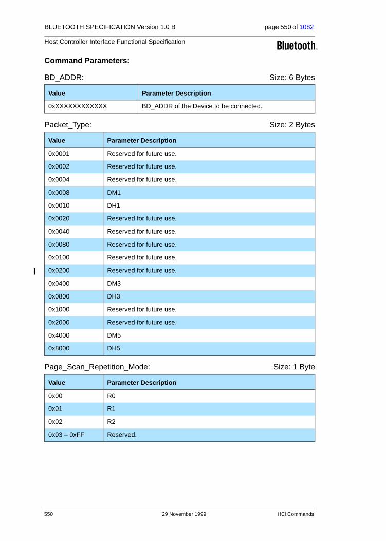
BLUETOOTH SPECIFICATION Version 1.0 B page 550 of 1082
Host Controller Interface Functional Specification
Command Parameters:
BD_ADDR: Size: 6 Bytes
Packet_Type: Size: 2 Bytes
Page_Scan_Repetition_Mode: Size: 1 Byte
Value Parameter Description
0xXXXXXXXXXXXX BD_ADDR of the Device to be connected.
Value Parameter Description
0x0001 Reserved for future use.
0x0002 Reserved for future use.
0x0004 Reserved for future use.
0x0008 DM1
0x0010 DH1
0x0020 Reserved for future use.
0x0040 Reserved for future use.
0x0080 Reserved for future use.
0x0100 Reserved for future use.
0x0200 Reserved for future use.
0x0400 DM3
0x0800 DH3
0x1000 Reserved for future use.
0x2000 Reserved for future use.
0x4000 DM5
0x8000 DH5
Value Parameter Description
0x00 R0
0x01 R1
0x02 R2
0x03 – 0xFF Reserved.
550 29 November 1999 HCI Commands

BLUETOOTH SPECIFICATION Version 1.0 B page 551 of 1082
Host Controller Interface Functional Specification
Page_Scan_Mode: Size: 1 Byte
Clock_Offset: Size: 2 Bytes
Allow_Role_Switch: Size: 1 Byte
Return Parameters:
None.
Event(s) generated (unless masked away):
When the Host Controller receives the Create Connection command, the Host Controller sends the Command Status event to the Host. In addition, when the LM determines the connection is established, the Host Controller, on both Bluetooth devices that form the connection, will send a Connection Complete event to each Host. The Connection Complete event contains the Connection Handle if this command is successful. Note: no Command Complete event will be sent by the Host Controller to indicate that this command has been completed. Instead, the Connection Complete event will indicate that this command has been completed.
Value Parameter Description
0x00 Mandatory Page Scan Mode.
0x01 Optional Page Scan Mode I.
0x02 Optional Page Scan Mode II.
0x03 Optional Page Scan Mode III.
0x04 – 0xFF Reserved.
Bit format Parameter Description
Bit 14.0 Bit 16.2 of CLKslave-CLKmaster.
Bit 15 Clock_Offset_Valid_Flag
Invalid Clock Offfset = 0
Valid Clock Offset = 1
Value Parameter Description
0x00 The local device will be a master, and will not accept a master-slave switch requested by the remote device at the connection setup.
0x01 The local device may be a master, or may become a slave after accepting a master-slave switch requested by the remote device at the connection setup.
0x02-0xFF Reserved for future use.
HCI Commands 29 November 1999 551

BLUETOOTH SPECIFICATION Version 1.0 B page 552 of 1082
Host Controller Interface Functional Specification
4.5.6 Disconnect
Description:
The Disconnection command is used to terminate an existing connection. The Connection_Handle command parameter indicates which connection is to be disconnected. The Reason command parameter indicates the reason for end-ing the connection. The remote Bluetooth device will receive the Reason com-mand parameter in the Disconnection Complete event. All SCO connections on a physical link should be disconnected before the ACL connection on the same physical connection is disconnected.
Command Parameters:
Connection_Handle: Size: 2 Bytes (12 Bits meaningful)
Reason: Size: 1 Byte
Return Parameters:
None.
Event(s) generated (unless masked away):
When the Host Controller receives the Disconnect command, it sends the Command Status event to the Host. The Disconnection Complete event will occur at each Host when the termination of the connection has completed, and indicates that this command has been completed. Note: No Command Complete event will be sent by the Host Controller to indicate that this command has been completed. Instead, the Disconnection Complete event will indicate that this command has been completed.
Command OCF Command Parameters Return Parameters
HCI_Disconnect 0x0006 Connection_Handle,
Reason
Value Parameter Description
0xXXXX Connection Handle for the connection being disconnected.
Range: 0x0000-0x0EFF (0x0F00 - 0x0FFF Reserved for future use)
Value Parameter Description
0x13-0x15, 0x1A
Other End Terminated Connection error codes (0x13-0x15) and Unsup-ported Remote Feature error code (0x1A) see Table 6.1 on page 745 for list of Error Codes.
552 29 November 1999 HCI Commands

BLUETOOTH SPECIFICATION Version 1.0 B page 553 of 1082
Host Controller Interface Functional Specification
4.5.7 Add_SCO_Connection
Description:
This command will cause the link manager to create a SCO connection using the ACL connection specified by the Connection_Handle command parameter. This command causes the local Bluetooth device to create a SCO connection. The Link Manager will determine how the new connection is established. This connection is determined by the current state of the device, its piconet, and the state of the device to be connected. The Packet_Type command parameter specifies which packet types the Link Manager should use for the connection. The Link Manager must only use the packet type(s) specified by the Packet_Type command parameter for sending HCI SCO Data Packets. Multi-ple packet types may be specified for the Packet_Type command parameter by performing a bitwise OR operation of the different packet types. The Link Man-ager may choose which packet type is to be used from the list of acceptable packet types. A Connection Handle for this connection is returned in the Con-nection Complete event (see below).Note: SCO-Connection can only be created when an ACL Connection already exists. For a definition of the different packet types, see the “Baseband Specifi-cation” on page 33.
Note: At least one packet type must be specified. The Host should enable as many packet types as possible for the Link Manager to perform efficiently. However, the Host must not enable packet types that the local device does not support.
Command Parameters:
Connection_Handle Size 2 Bytes (12 Bits meaningful)
Command OCF Command ParametersReturn Parameters
HCI_Add_SCO_Connection 0x0007 Connection_Handle,
Packet_Type
Value Parameter Description
0xXXXX Connection Handle for the ACL connection being used to create an SCO connection.
Range: 0x0000-0x0EFF (0x0F00 - 0x0FFF Reserved for future use)
HCI Commands 29 November 1999 553
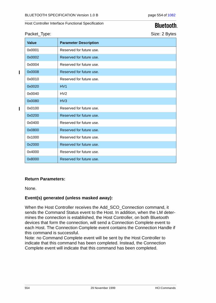
BLUETOOTH SPECIFICATION Version 1.0 B page 554 of 1082
Host Controller Interface Functional Specification
Packet_Type: Size: 2 Bytes
Return Parameters:
None.
Event(s) generated (unless masked away):
When the Host Controller receives the Add_SCO_Connection command, it sends the Command Status event to the Host. In addition, when the LM deter-mines the connection is established, the Host Controller, on both Bluetooth devices that form the connection, will send a Connection Complete event to each Host. The Connection Complete event contains the Connection Handle if this command is successful. Note: no Command Complete event will be sent by the Host Controller to indicate that this command has been completed. Instead, the Connection Complete event will indicate that this command has been completed.
Value Parameter Description
0x0001 Reserved for future use.
0x0002 Reserved for future use.
0x0004 Reserved for future use.
0x0008 Reserved for future use.
0x0010 Reserved for future use.
0x0020 HV1
0x0040 HV2
0x0080 HV3
0x0100 Reserved for future use.
0x0200 Reserved for future use.
0x0400 Reserved for future use.
0x0800 Reserved for future use.
0x1000 Reserved for future use.
0x2000 Reserved for future use.
0x4000 Reserved for future use.
0x8000 Reserved for future use.
554 29 November 1999 HCI Commands

BLUETOOTH SPECIFICATION Version 1.0 B page 555 of 1082
Host Controller Interface Functional Specification
4.5.8 Accept_Connection_Request
Description:
The Accept_Connection_Request command is used to accept a new incoming connection request. The Accept_Connection_Request command shall only be issued after a Connection Request event has occurred. The Connection Request event will return the BD_ADDR of the device which is requesting the connection. This command will cause the Link Manager to create a connection to the Bluetooth device, with the BD_ADDR specified by the command param-eters. The Link Manager will determine how the new connection will be estab-lished. This will be determined by the current state of the device, its piconet, and the state of the device to be connected. The Role command parameter allows the Host to specify if the Link Manager shall perform a Master-Slave switch, and become the Master for this connection. Also, the decision to accept a connection must be completed before the connection accept timeout expires on the local Bluetooth Module.Note: when accepting SCO connection request, the Role parameter is not used and will be ignored by the Host Controller.
Command Parameters:
BD_ADDR: Size: 6 Bytes
Role: Size: 1 Byte
Return Parameters:
None.
Command OCF Command Parameters Return Parameters
HCI_Accept_ConnectionRequest
0x0009 BD_ADDR,
Role
Value Parameter Description
0xXXXXXXXXXXXX BD_ADDR of the Device to be connected
Value Parameter Description
0x00 Become the Master for this connection. The LM will perform the Master/Slave switch.
0x01 Remain the Slave for this connection. The LM will NOT perform the Mas-ter/Slave switch.
HCI Commands 29 November 1999 555

BLUETOOTH SPECIFICATION Version 1.0 B page 556 of 1082
Host Controller Interface Functional Specification
Event(s) generated (unless masked away):
The Accept_Connection_Request command will cause the Command Status event to be sent from the Host Controller when the Host Controller begins set-ting up the connection. In addition, when the Link Manager determines the con-nection is established, the Host Controllers on both Bluetooth devices that form the connection will send a Connection Complete event to each Host. The Con-nection Complete event contains the Connection Handle if this command is successful. Note: no Command Complete event will be sent by the Host Controller to indicate that this command has been completed. Instead, the Connection Complete event will indicate that this command has been completed.
556 29 November 1999 HCI Commands

BLUETOOTH SPECIFICATION Version 1.0 B page 557 of 1082
Host Controller Interface Functional Specification
4.5.9 Reject_Connection_Request
Description:
The Reject_Connection_Request command is used to decline a new incoming connection request. The Reject_Connection_Request command shall only be called after a Connection Request event has occurred. The Connection Request event will return the BD_ADDR of the device that is requesting the connection. The Reason command parameter will be returned to the connect-ing device in the Status parameter of the Connection Complete event returned to the Host of the connection device, to indicate why the connection was declined.
Command Parameters:
BD_ADDR: Size: 6 Bytes
Reason: Size: 1 Byte
Return Parameters:
None.
Event(s) generated (unless masked away):
When the Host Controller receives the Reject_Connection_Request command, the Host Controller sends the Command Status event to the Host. A Connec-tion Complete event will then be sent, both to the local Host and to the Host of the device attempting to make the connection. The Status parameter of the Connection Complete event, which is sent to the Host of the device attempting to make the connection, will contain the Reason command parameter from this command. Note: no Command Complete event will be sent by the Host Controller to indicate that this command has been completed. Instead, the Connection Complete event will indicate that this command has been completed.
Command OCF Command Parameters Return Parameters
HCI_Reject_Connection_Request
0x000A BD_ADDR, Reason
Value Parameter Description
0xXXXXXXXXXXXX BD_ADDR of the Device to reject the connection from.
Value Parameter Description
0x0D-0x0F Host Reject Error Code. See Table 6.1 on page 745 for list of Error Codes and descriptions.
HCI Commands 29 November 1999 557

BLUETOOTH SPECIFICATION Version 1.0 B page 558 of 1082
Host Controller Interface Functional Specification
4.5.10 Link_Key_Request_Reply
Description:
The Link_Key_Request_Reply command is used to reply to a Link Key Request event from the Host Controller, and specifies the Link Key stored on the Host to be used as the link key for the connection with the other Bluetooth Device specified by BD_ADDR. The Link Key Request event will be generated when the Host Controller needs a Link Key for a connection.
When the Host Controller generates a Link Key Request event in order for the local Link Manager to respond to the request from the remote Link Manager (as a result of a Create_Connection or Authentication_Requested command from the remote Host), the local Host must respond with either a Link_Key_Request_Reply or Link_Key_Request_Negative_Reply command before the remote Link Manager detects LMP response timeout. (See “Link Manager Protocol” on page 185.)
Command Parameters:
BD_ADDR: Size: 6 Bytes
Link_Key: Size: 16 Bytes
Return Parameters:
Status: Size: 1 Byte
Command OCFCommand Parameters Return Parameters
HCI_Link_Key_Request_Reply 0x000B BD_ADDR, Link_Key Status, BD_ADDR
Value Parameter Description
0xXXXXXXXXXXXX BD_ADDR of the Device of which the Link Key is for.
Value Parameter Description
0xXXXXXXXXXXXXXXXXXXXXXXXXXXXXXXXX
Link Key for the associated BD_ADDR.
Value Parameter Description
0x00 Link_Key_Request_Reply command succeeded.
0x01-0xFF Link_Key_Request_Reply command failed. See Table 6.1 on page 745 for list of Error Codes.
558 29 November 1999 HCI Commands
BLUETOOTH SPECIFICATION Version 1.0 B page 559 of 1082
Host Controller Interface Functional Specification
BD_ADDR: Size: 6 Bytes
Event(s) generated (unless masked away):
The Link_Key_Request_Reply command will cause a Command Complete event to be generated.
Value Parameter Description
0xXXXXXXXXXXXX
BD_ADDR of the Device of which the Link Key request reply has completed.
HCI Commands 29 November 1999 559

BLUETOOTH SPECIFICATION Version 1.0 B page 560 of 1082
Host Controller Interface Functional Specification
4.5.11 Link_Key_Request_Negative_Reply
Description:
The Link_Key_Request_Negative_Reply command is used to reply to a Link Key Request event from the Host Controller if the Host does not have a stored Link Key for the connection with the other Bluetooth Device specified by BD_ADDR. The Link Key Request event will be generated when the Host Con-troller needs a Link Key for a connection.
When the Host Controller generates a Link Key Request event in order for the local Link Manager to respond to the request from the remote Link Manager (as a result of a Create_Connection or Authentication_Requested command from the remote Host), the local Host must respond with either a Link_Key_Request_Reply or Link_Key_Request_Negative_Reply command before the remote Link Manager detects LMP response timeout. (See “Link Manager Protocol” on page 185.)
Command Parameters:
BD_ADDR: Size: 6 Bytes
Return Parameters:
Status: Size: 1 Byte
BD_ADDR: Size: 6 Bytes
Event(s) generated (unless masked away):
The Link_Key_Request_Negative_Reply command will cause a Command Complete event to be generated.
Command OCF Command Parameters Return Parameters
HCI_Link_Key_Request_Negative_Reply
0x000C BD_ADDR Status, BD_ADDR
Value Parameter Description
0xXXXXXXXXXXXX
BD_ADDR of the Device which the Link Key is for.
Value Parameter Description
0x00 Link_Key_Request_Negative_Reply command succeeded.
0x01-0xFF Link_Key_Request_Negative_Reply command failed. See Table 6.1 on page 745 for list of Error Codes.
Value Parameter Description
0xXXXXXXXXXXXX
BD_ADDR of the Device which the Link Key request negative reply has completed.
560 29 November 1999 HCI Commands

BLUETOOTH SPECIFICATION Version 1.0 B page 561 of 1082
Host Controller Interface Functional Specification
4.5.12 PIN_Code_Request_Reply
Description:
The PIN_Code_Request_Reply command is used to reply to a PIN Code request event from the Host Controller, and specifies the PIN code to use for a connection. The PIN Code Request event will be generated when a connection with remote initiating device has requested pairing.
When the Host Controller generates a PIN Code Request event in order for the local Link Manager to respond to the request from the remote Link Manager (as a result of a Create_Connection or Authentication_Requested command from the remote Host), the local Host must respond with either a PIN_Code_Request_Reply or PIN_Code_Request_Negative_Reply com-mand before the remote Link Manager detects LMP response timeout. (See “Link Manager Protocol” on page 185.)
Command Parameters:
BD_ADDR: Size: 6 Bytes
PIN_Code_Length: Size: 1 Byte
PIN_Code: Size: 16 Bytes
Command OCFCommand Parameters Return Parameters
HCI_PIN_Code_Request_Reply 0x000D BD_ADDR,
PIN_Code_Length,
PIN_Code
Status, BD_ADDR
Value Parameter Description
0xXXXXXXXXXXXX
BD_ADDR of the Device which the PIN code is for.
Value Parameter Description
0xXX The PIN code length specifics the length, in bytes, of the PIN code to be used.
Range: 0x01-0x10
Value Parameter Description
0xXXXXXXXXXXXXXXXXXXXXXXXXXXXXXXXX
PIN code for the device that is to be connected. The Host should insure that strong PIN Codes are used. PIN Codes can be up to a maximum of 128 bits. The MSB of the PIN Code occupies byte zero.
HCI Commands 29 November 1999 561

BLUETOOTH SPECIFICATION Version 1.0 B page 562 of 1082
Host Controller Interface Functional Specification
Return Parameters:
Status: Size: 1 Byte
BD_ADDR: Size: 6 Bytes
Event(s) generated (unless masked away):
The PIN_Code_Request_Reply command will cause a Command Complete event to be generated.
Value Parameter Description
0x00 PIN_Code_Request_Reply command succeeded.
0x01-0xFF PIN_Code_Request_Reply command failed. See Table 6.1 on page 745 for list of Error Codes.
Value Parameter Description
0xXXXXXXXXXXXX
BD_ADDR of the Device which the PIN Code request reply has completed.
562 29 November 1999 HCI Commands
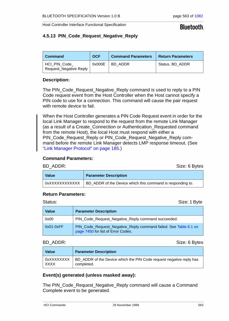
BLUETOOTH SPECIFICATION Version 1.0 B page 563 of 1082
Host Controller Interface Functional Specification
4.5.13 PIN_Code_Request_Negative_Reply
Description:
The PIN_Code_Request_Negative_Reply command is used to reply to a PIN Code request event from the Host Controller when the Host cannot specify a PIN code to use for a connection. This command will cause the pair request with remote device to fail.
When the Host Controller generates a PIN Code Request event in order for the local Link Manager to respond to the request from the remote Link Manager (as a result of a Create_Connection or Authentication_Requested command from the remote Host), the local Host must respond with either a PIN_Code_Request_Reply or PIN_Code_Request_Negative_Reply com-mand before the remote Link Manager detects LMP response timeout. (See “Link Manager Protocol” on page 185.)
Command Parameters:
BD_ADDR: Size: 6 Bytes
Return Parameters:
Status: Size: 1 Byte
BD_ADDR: Size: 6 Bytes
Event(s) generated (unless masked away):
The PIN_Code_Request_Negative_Reply command will cause a Command Complete event to be generated.
Command OCF Command Parameters Return Parameters
HCI_PIN_Code_Request_Negative Reply
0x000E BD_ADDR Status, BD_ADDR
Value Parameter Description
0xXXXXXXXXXXXX BD_ADDR of the Device which this command is responding to.
Value Parameter Description
0x00 PIN_Code_Request_Negative_Reply command succeeded.
0x01-0xFF PIN_Code_Request_Negative_Reply command failed. See Table 6.1 on page 7450 for list of Error Codes.
Value Parameter Description
0xXXXXXXXXXXXX
BD_ADDR of the Device which the PIN Code request negative reply has completed.
HCI Commands 29 November 1999 563

BLUETOOTH SPECIFICATION Version 1.0 B page 564 of 1082
Host Controller Interface Functional Specification
4.5.14 Change_Connection_Packet_Type
Description:
The Change_Connection_Packet_Type command is used to change which packet types can be used for a connection that is currently established. This allows current connections to be dynamically modified to support different types of user data. The Packet_Type command parameter specifies which packet types the Link Manager can use for the connection. The Link Manager must only use the packet type(s) specified by the Packet_Type command parameter for sending HCI Data Packets. The interpretation of the value for the Packet_Type command parameter will depend on the Link_Type command parameter returned in the Connection Complete event at the connection setup. Multiple packet types may be specified for the Packet_Type command parame-ter by bitwise OR operation of the different packet types. For a definition of the different packet types see the “Baseband Specification” on page 33.
Note: At least one packet type must be specified. The Host should enable as many packet types as possible for the Link Manager to perform efficiently. However, the Host must not enable packet types that the local device does not support.
Command Parameters:
Connection_Handle: Size: 2 Bytes (12 Bits meaningful)
Packet_Type: Size: 2 Bytes
For ACL Link_Type
Command OCF Command Parameters Return Parameters
HCI_Change_Connection_
Packet_Type
0x000F Connection_Handle,
Packet_Type
Value Parameter Description
0xXXXX Connection Handle to be used to for transmitting and receiving voice or data. Returned from creating a connection.
Range: 0x0000-0x0EFF (0x0F00 - 0x0FFF Reserved for future use)
Value Parameter Description
0x0001 Reserved for future use.
0x0002 Reserved for future use.
0x0004 Reserved for future use.
0x0008 DM1
564 29 November 1999 HCI Commands

BLUETOOTH SPECIFICATION Version 1.0 B page 565 of 1082
Host Controller Interface Functional Specification
For SCO Link Type
0x0010 DH1
0x0020 Reserved for future use.
0x0040 Reserved for future use.
0x0080 Reserved for future use.
0x0100 Reserved for future use.
0x0200 Reserved for future use.
0x0400 DM3
0x0800 DH3
0x1000 Reserved for future use.
0x2000 Reserved for future use.
0x4000 DM5
0x8000 DH5
Value Parameter Description
0x0001 Reserved for future use.
0x0002 Reserved for future use.
0x0004 Reserved for future use.
0x0008 Reserved for future use.
0x0010 Reserved for future use.
0x0020 HV1
0x0040 HV2
0x0080 HV3
0x0100 Reserved for future use.
0x0200 Reserved for future use.
0x0400 Reserved for future use.
0x0800 Reserved for future use.
0x1000 Reserved for future use.
0x2000 Reserved for future use.
0x4000 Reserved for future use.
0x8000 Reserved for future use.
Value Parameter Description
HCI Commands 29 November 1999 565

BLUETOOTH SPECIFICATION Version 1.0 B page 566 of 1082
Host Controller Interface Functional Specification
Return Parameters:
None.
Event(s) generated (unless masked away):
When the Host Controller receives the Change Connection Packet Type com-mand, the Host Controller sends the Command Status event to the Host. In addition, when the Link Manager determines the packet type has been changed for the connection, the Host Controller on the local device will send a Connection Packet Type Changed event to the Host. This will be done at the local side only. Note: no Command Complete event will be sent by the Host Controller to indicate that this command has been completed. Instead, the Connection Packet Type Changed event will indicate that this command has been completed.
566 29 November 1999 HCI Commands

BLUETOOTH SPECIFICATION Version 1.0 B page 567 of 1082
Host Controller Interface Functional Specification
4.5.15 Authentication_Requested
Description:
The Authentication_Requested command is used to try to authenticate the remote device associated with the specified Connection Handle. The Host must not issue the Authentication_Requested command with a Connection_Handle corresponding to an encrypted link. On an authentication failure, the Host Controller or Link Manager shall not automatically detach the link. The Host is responsible for issuing a Disconnect command to terminate the link if the action is appropriate.Note: the Connection_Handle command parameter is used to identify the other Bluetooth device, which forms the connection. The Connection Handle should be a Connection Handle for an ACL connection.
Command Parameters:
Connection_Handle: Size 2 Bytes (12 Bits meaningful)
Return Parameters:
None.
Event(s) generated (unless masked away):
When the Host Controller receives the Authentication_Requested command, it sends the Command Status event to the Host. The Authentication Complete event will occur when the authentication has been completed for the connec-tion and is indication that this command has been completed. Note: no Command Complete event will be sent by the Host Controller to indicate that this command has been completed. Instead, the Authentication Complete event will indicate that this command has been completed.
Note: When the local or remote Host Controller does not have a link key for the specified Connection_Handle, it will request the link key from its Host, before the local Host finally receives the Authentication Complete event.
Command OCF Command Parameters Return Parameters
HCI_Authentication_
Requested
0x0011 Connection_Handle
Value Parameter Description
0xXXXX Connection Handle to be used to set up authentication for all Connection Handles with the same Bluetooth device end-point as the specified Con-nection Handle.
Range: 0x0000-0x0EFF (0x0F00 - 0x0FFF Reserved for future use)
HCI Commands 29 November 1999 567

BLUETOOTH SPECIFICATION Version 1.0 B page 568 of 1082
Host Controller Interface Functional Specification
4.5.16 Set_Connection_Encryption
Description:
The Set_Connection_Encryption command is used to enable and disable the link level encryption. Note: the Connection_Handle command parameter is used to identify the other Bluetooth device which forms the connection. The Connection Handle should be a Connection Handle for an ACL connection. While the encryption is being changed, all ACL traffic must be turned off for all Connection Handles associated with the remote device.
Command Parameters:
Connection_Handle: Size 2 Bytes (12 Bits meaningful)
Encryption_Enable: Size: 1 Byte
Return Parameters:
None.
Event(s) generated (unless masked away):
When the Host Controller receives the Set_Connection_Encryption command, the Host Controller sends the Command Status event to the Host. When the Link Manager has completed enabling/disabling encryption for the connection, the Host Controller on the local Bluetooth device will send an Encryption Change event to the Host, and the Host Controller on the remote device will also generate an Encryption Change event. Note: no Command Complete event will be sent by the Host Controller to indi-cate that this command has been completed. Instead, the Encryption Change event will indicate that this command has been completed.
Command OCF Command Parameters Return Parameters
HCI_Set_Connection_Encryption
0x0013 Connection_Handle,Encryption_Enable
Value Parameter Description
0xXXXX Connection Handle to be used to enable/disable the link layer encryption for all Connection Handles with the same Bluetooth device end-point as the specified Connection Handle.
Range: 0x0000-0x0EFF (0x0F00 - 0x0FFF Reserved for future use)
Value Parameter Description
0x00 Turn Link Level Encryption OFF.
0x01 Turn Link Level Encryption ON.
568 29 November 1999 HCI Commands

BLUETOOTH SPECIFICATION Version 1.0 B page 569 of 1082
Host Controller Interface Functional Specification
4.5.17 Change_Connection_Link_Key
Description:
The Change_Connection_Link_Key command is used to force both devices of a connection associated with the connection handle to generate a new link key. The link key is used for authentication and encryption of connections. Note: the Connection_Handle command parameter is used to identify the other Bluetooth device forming the connection. The Connection Handle should be a Connection Handle for an ACL connection. If the connection encryption is enabled, and the temporary link key is currently used, then the Bluetooth master device will automatically restart the encryption.
Command Parameters:
Connection_Handle: Size 2 Bytes (12 Bits meaningful)
Return Parameters:
None.
Event(s) generated (unless masked away):
When the Host Controller receives the Change_Connection_Link_Key com-mand, the Host Controller sends the Command Status event to the Host. When the Link Manager has changed the Link Key for the connection, the Host Con-troller on the local Bluetooth device will send a Link Key Notification event and a Change Connection Link Key Complete event to the Host, and the Host Con-troller on the remote device will also generate a Link Key Notification event. The Link Key Notification event indicates that a new connection link key is valid for the connection. Note: no Command Complete event will be sent by the Host Controller to indicate that this command has been completed. Instead, the Change Connection Link Key Complete event will indicate that this command has been completed.
Command OCF Command Parameters Return Parameters
HCI_Change_Connection_
Link_Key
0x0015 Connection_Handle
Value Parameter Description
0xXXXX Connection Handle used to identify a connection.
Range: 0x0000-0x0EFF (0x0F00 - 0x0FFF Reserved for future use)
HCI Commands 29 November 1999 569

BLUETOOTH SPECIFICATION Version 1.0 B page 570 of 1082
Host Controller Interface Functional Specification
4.5.18 Master_Link_Key
Description:
The Master Link Key command is used to force the device that is master of the piconet to use the temporary link key of the master device, or the semi-permanent link keys. The temporary link key is used for encryption of broad-cast messages within a piconet, and the semi-permanent link keys are used for private encrypted point-to-point communication. The Key_Flag command parameter is used to indicate which Link Key (temporary link key of the Master, or the semi-permanent link keys) shall be used.
Command Parameters:
Key_Flag: Size: 1 Byte
Return Parameters:
None.
Event(s) generated (unless masked away):
When the Host Controller receives the Master_Link_Key command, the Host Controller sends the Command Status event to the Host. When the Link Man-ager has changed link key, the Host Controller on both the local and the remote device will send a Master Link Key Complete event to the Host. The Connec-tion Handle on the master side will be a Connection Handle for one of the exist-ing connections to a slave. On the slave side, the Connection Handle will be a Connection Handle to the initiating master.
The Master Link Key Complete event contains the status of this command.Note: no Command Complete event will be sent by the Host Controller to indicate that this command has been completed. Instead, the Master Link Key Complete event will indicate that this command has been completed.
Command OCF Command Parameters Return Parameters
HCI_Master_Link_Key 0x0017 Key_Flag
Value Parameter Description
0x00 Use semi-permanent Link Keys.
0x01 Use Temporary Link Key.
570 29 November 1999 HCI Commands

BLUETOOTH SPECIFICATION Version 1.0 B page 571 of 1082
Host Controller Interface Functional Specification
4.5.19 Remote_Name_Request
Description:
The Remote_Name_Request command is used to obtain the user-friendly name of another Bluetooth device. The user-friendly name is used to enable the user to distinguish one Bluetooth device from another. The BD_ADDR command parameter is used to identify the device for which the user-friendly name is to be obtained. The Page_Scan_Repetition_Mode and Page_Scan_Mode command parameters specify the page scan modes sup-ported by the remote device with the BD_ADDR. This is the information that was acquired during the inquiry process. The Clock_Offset parameter is the difference between its own clock and the clock of the remote device with BD_ADDR. Only bits 2 through 16 of the difference are used and they are mapped to this parameter as bits 0 through 14 respectively. A Clock_Offset_Valid_Flag, located in bit 15 of the Clock_Offset command parameter, is used to indicate if the Clock Offset is valid or not. Note: if no connection exists between the local device and the device corre-sponding to the BD_ADDR, a temporary link layer connection will be estab-lished to obtain the name of the remote device.
Command Parameters:
BD_ADDR: Size: 6 Bytes
Page_Scan_Repetition_Mode: Size: 1 Byte
Command OCF Command ParametersReturn Parameters
HCI_Remote_Name_Request 0x0019 BD_ADDR,
Page_Scan_Repetition_Mode,
Page_Scan_Mode,
Clock_Offset
Value Parameter Description
0xXXXXXXXXXXXX
BD_ADDR for the device whose name is requested.
Value Parameter Description
0x00 R0
0x01 R1
0x02 R2
0x03 – 0xFF Reserved.
HCI Commands 29 November 1999 571

BLUETOOTH SPECIFICATION Version 1.0 B page 572 of 1082
Host Controller Interface Functional Specification
Page_Scan_Mode: Size: 1 Byte
Clock_Offset: Size: 2 Bytes
Return Parameters:
None.
Event(s) generated (unless masked away):
When the Host Controller receives the Remote_Name_Request command, the Host Controller sends the Command Status event to the Host. When the Link Manager has completed the LMP messages to obtain the remote name, the Host Controller on the local Bluetooth device will send a Remote Name Request Complete event to the Host. Note: no Command Complete event will be sent by the Host Controller to indicate that this command has been com-pleted. Instead, only the Remote Name Request Complete event will indicate that this command has been completed.
Value Parameter Description
0x00 Mandatory Page Scan Mode.
0x01 Optional Page Scan Mode I.
0x02 Optional Page Scan Mode II.
0x03 Optional Page Scan Mode III.
0x04 – 0xFF Reserved.
Bit format Parameter Description
Bit 14.0 Bit 16.2 of CLKslave-CLKmaster.
Bit 15 Clock_Offset_Valid_Flag
Invalid Clock Offfset = 0
Valid Clock Offset = 1
572 29 November 1999 HCI Commands

BLUETOOTH SPECIFICATION Version 1.0 B page 573 of 1082
Host Controller Interface Functional Specification
4.5.20 Read_Remote_Supported_Features
Description:
This command requests a list of the supported features for the remote device identified by the Connection_Handle parameter. The Connection_Handle must be a Connection_Handle for an ACL connection. The Read Remote Supported Features Complete event will return a list of the LMP features. For details see “Link Manager Protocol” on page 185.
Command Parameters:
Connection_Handle: Size: 2 Bytes (12 Bits meaningful)
Return Parameters:
None.
Event(s) generated (unless masked away):
When the Host Controller receives the Read_Remote_Supported_Features command, the Host Controller sends the Command Status event to the Host. When the Link Manager has completed the LMP messages to determine the remote features, the Host Controller on the local Bluetooth device will send a Read Remote Supported Features Complete event to the Host. The Read Remote Supported Features Complete event contains the status of this com-mand, and parameters describing the supported features of the remote device. Note: no Command Complete event will be sent by the Host Controller to indi-cate that this command has been completed. Instead, the Read Remote Sup-ported Features Complete event will indicate that this command has been completed.
Command OCF Command Parameters
Return Parameters
HCI_Read_Remote_Supported_Features 0x001B Connection_Handle
Value Parameter Description
0xXXXX Specifies which Connection Handle’s LMP-supported features list to get.
Range: 0x0000-0x0EFF (0x0F00 - 0x0FFF Reserved for future use)
HCI Commands 29 November 1999 573

BLUETOOTH SPECIFICATION Version 1.0 B page 574 of 1082
Host Controller Interface Functional Specification
4.5.21 Read_Remote_Version_Information
Description:
This command will obtain the values for the version information for the remote Bluetooth device identified by the Connection_Handle parameter. The Connection_Handle must be a Connection_Handle for an ACL connection.
Command Parameters:
Connection_Handle: Size: 2 Bytes (12 Bits meaningful)
Return Parameters:
None.
Event(s) generated (unless masked away):
When the Host Controller receives the Read_Remote_Version_Information command, the Host Controller sends the Command Status event to the Host. When the Link Manager has completed the LMP messages to determine the remote version information, the Host Controller on the local Bluetooth device will send a Read Remote Version Information Complete event to the Host. The Read Remote Version Information Complete event contains the status of this command, and parameters describing the version and subversion of the LMP used by the remote device. Note: no Command Complete event will be sent by the Host Controller to indicate that this command has been completed. Instead, the Read Remote Version Information Complete event will indicate that this command has been completed.
Command OCF Command ParametersReturn Parameters
HCI_Read_Remote_Version_
Information
0x001D Connection_Handle
Value Parameter Description
0xXXXX Specifies which Connection Handle’s version information to get.
Range: 0x0000-0x0EFF (0x0F00 - 0x0FFF Reserved for future use)
574 29 November 1999 HCI Commands

BLUETOOTH SPECIFICATION Version 1.0 B page 575 of 1082
Host Controller Interface Functional Specification
4.5.22 Read_Clock_Offset
Description:
Both the System Clock and the clock offset of a remote device are used to determine what hopping frequency is used by a remote device for page scan. This command allows the Host to read clock offset of remote devices. The Connection_Handle must be a Connection_Handle for an ACL connection. This command could be used to facilitate handoffs of Bluetooth devices from one device to another.
Command Parameters:
Connection_Handle: Size: 2 Bytes (12 bits meaningful)
Return Parameters:
None.
Event(s) generated (unless masked away):
When the Host Controller receives the Read_Clock_Offset command, the Host Controller sends the Command Status event to the Host. If this command was requested at the master and the Link Manager has completed the LMP mes-sages to obtain the Clock Offset information, the Host Controller on the local Bluetooth device will send a Read Clock Offset Complete event to the Host.Note: no Command Complete event will be sent by the Host Controller to indicate that this command has been completed. Instead, only the Read Clock Offset Complete event will indicate that this command has been completed. If the command is requested at the slave, the LM will immediately send a Command Status event and a Read Clock Offset Complete event to the Host, without an exchange of LMP PDU.
Command OCF Command Parameters Return Parameters
HCI_Read_Clock_Offset 0x001F Connection_Handle
Value Parameter Description
0xXXXX Specifies which Connection Handle’s Clock Offset parameter is returned.
Range: 0x0000-0x0EFF (0x0F00 - 0x0FFF Reserved for future use)
HCI Commands 29 November 1999 575

BLUETOOTH SPECIFICATION Version 1.0 B page 576 of 1082
Host Controller Interface Functional Specification
4.6 LINK POLICY COMMANDS
The Link Policy Commands provide methods for the Host to affect how the Link Manager manages the piconet. When Link Policy Commands are used, the LM still controls how Bluetooth piconets and scatternets are established and main-tained, depending on adjustable policy parameters. These policy commands modify the Link Manager behavior that can result in changes to the link layer connections with Bluetooth remote devices. Note: only one ACL connection can exist between two Bluetooth Devices, and therefore there can only be one ACL HCI Connection Handle for each physical link layer Connection. The Bluetooth Host Controller provides policy adjust-ment mechanisms to provide support for a number of different policies. This capability allows one Bluetooth module to be used to support many different usage models, and the same Bluetooth module can be incorporated in many different types of Bluetooth devices. For the Link Policy Commands, the OGF is defined as 0x02.
Command Command Summary Description
Hold_Mode The Hold_Mode command is used to alter the behavior of the LM and have the LM place the local or remote device into the hold mode.
Sniff_Mode The Sniff_Mode command is used to alter the behavior of the LM and have the LM place the local or remote device into the sniff mode.
Exit_Sniff_Mode The Exit_Sniff_Mode command is used to end the sniff mode for a connection handle which is currently in sniff mode.
Park_Mode The Park_Mode command is used to alter the behavior of the LM and have the LM place the local or remote device into the Park mode.
Exit_Park_Mode The Exit_Park_Mode command is used to switch the Bluetooth device from park mode back to active mode.
QoS_Setup The QoS_Setup command is used to specify Qual-ity of Service parameters for a connection handle.
Role_Discovery The Role_Discovery command is used for a Blue-tooth device to determine which role the device is performing for a particular Connection Handle.
Switch_Role The Switch_Role command is used for a Bluetooth device switch the current role the device is per-forming for a particular connection with the speci-fied Bluetooth device
576 29 November 1999 HCI Commands

BLUETOOTH SPECIFICATION Version 1.0 B page 577 of 1082
Host Controller Interface Functional Specification
Command Command Summary Description
Read_Link_Policy_Settings The Read_Link_Policy_Settings command will read the Link Policy settings for the specified Con-nection Handle. The Link Policy settings allow the Host to specify which Link Modes the LM can use for the specified Connection Handle.
Write_Link_Policy_Settings The Write_Link_Policy_Settings command will write the Link Policy settings for the specified Con-nection Handle. The Link Policy settings allow the Host to specify which Link Modes the LM can use for the specified Connection Handle.
HCI Commands 29 November 1999 577

BLUETOOTH SPECIFICATION Version 1.0 B page 578 of 1082
Host Controller Interface Functional Specification
4.6.1 Hold_Mode
Description:
The Hold_Mode command is used to alter the behavior of the Link Manager, and have it place the ACL baseband connection associated by the specified Connection Handle into the hold mode. The Hold_Mode_Max_Interval and Hold_Mode_Min_Interval command parameters specify the length of time the Host wants to put the connection into the hold mode. The local and remote devices will negotiate the length in the hold mode. The Hold_Mode_Max_Interval parameter is used to specify the maximum length of the Hold interval for which the Host may actually enter into the hold mode after negotiation with the remote device. The Hold interval defines the amount of time between when the Hold Mode begins and when the Hold Mode is completed. The Hold_Mode_Min_Interval parameter is used to specify the minimum length of the Hold interval for which the Host may actually enter into the hold mode after the negotiation with the remote device. Therefore the Hold_Mode_Min_Interval cannot be greater than the Hold_Mode_Max_Interval. The Host Controller will return the actual Hold interval in the Interval parameter of the Mode Change event, if the command is successful. This command enables the Host to sup-port a low-power policy for itself or several other Bluetooth devices, and allows the devices to enter Inquiry Scan, Page Scan, and a number of other possible actions. Note: the connection handle cannot be of the SCO link type.
Command Parameters:
Connection_Handle: Size: 2 Bytes (12 Bits meaningful)
Hold_Mode_Max_Interval: Size: 2 Bytes
Command OCF Command Parameters Return Parameters
HCI_Hold_Mode 0x0001 Connection_Handle,
Hold_Mode_Max_Interval,
Hold_Mode_Min_Interval
Value Parameter Description
0xXXXX Connection Handle to be used to identify a connection.
Range: 0x0000-0x0EFF (0x0F00 - 0x0FFF Reserved for future use)
Value Parameter Description
N = 0xXXXX Maximum acceptable number of Baseband slots to wait in Hold Mode.
Time Length of the Hold = N * 0.625 msec (1 Baseband slot)
Range for N: 0x0001-0xFFFF
Time Range: 0.625ms - 40.9 sec
578 29 November 1999 HCI Commands

BLUETOOTH SPECIFICATION Version 1.0 B page 579 of 1082
Host Controller Interface Functional Specification
Hold_Mode_Min_Interval: Size: 2 Bytes
Return Parameters:
None.
Event(s) generated (unless masked away):
The Host Controller sends the Command Status event for this command to the Host when it has received the Hold_Mode command. The Mode Change event will occur when the Hold Mode has started and the Mode Change event will occur again when the Hold Mode has completed for the specified connection handle. The Mode Change event signaling the end of the Hold Mode is an esti-mation of the hold mode ending if the event is for a remote Bluetooth device.Note: no Command Complete event will be sent by the Host Controller to indicate that this command has been completed. Instead, only the Mode Change event will indicate that this command has been completed. If an error occurs after the Command Status event has occurred, then the status in the Mode Change event will indicate the error.
Value Parameter Description
N = 0xXXXX Minimum acceptable number of Baseband slots to wait in Hold Mode.
Time Length of the Hold = N * 0.625 msec (1 Baseband slot)
Range for N: 0x0001-0xFFFF
Time Range: 0.625 msec - 40.9 sec
HCI Commands 29 November 1999 579

BLUETOOTH SPECIFICATION Version 1.0 B page 580 of 1082
Host Controller Interface Functional Specification
4.6.2 Sniff_Mode
Description:
The Sniff Mode command is used to alter the behavior of the Link Manager and have it place the ACL baseband connection associated with the specified Con-nection Handle into the sniff mode. The Connection_Handle command param-eter is used to identify which ACL link connection is to be placed in sniff mode. The Sniff_Max_Interval and Sniff_Min_Interval command parameters are used to specify the requested acceptable maximum and minimum periods in the Sniff Mode. The Sniff_Min_Interval cannot be greater than the Sniff_Max_Interval. The sniff interval defines the amount of time between each consecutive sniff period. The Host Controller will return the actual sniff interval in the Interval parameter of the Mode Change event, if the command is suc-cessful. The slave will listen at the end of every actual sniff interval, for the period specified by the Sniff_Attempt command parameter. The slave will con-tinue listening for packets for an additional period specified by Sniff_Timeout, as long as it is receiving packets. This command enables the Host to support a low-power policy for itself or several other Bluetooth devices, and allows the devices to enter Inquiry Scan, Page Scan, and a number of other possible actions.Note: in addition, the connection handle cannot be one of SCO link type.
Command Parameters:
Connection_Handle: Size: 2 Bytes (12 Bits meaningful)
Sniff_Max_Interval: Size: 2 Byte
Command OCF Command Parameters Return Parameters
HCI_Sniff_Mode 0x0003 Connection_Handle,
Sniff_Max_Interval,
Sniff_Min_Interval,
Sniff_Attempt,
Sniff_Timeout
Value Parameter Description
0xXXXX Connection Handle to be used to identify a connection.
Range: 0x0000-0x0EFF (0x0F00 - 0x0FFF Reserved for future use)
Value Parameter Description
N = 0xXXXX Maximum acceptable number of Baseband slots between each sniff period.
(Sniff_Max_Interval >= Sniff_Min_Interval)
Length = N * 0.625 msec (1 Baseband slot)
Range for N: 0x0001 – 0xFFFF
Time Range: 0.625 msec - 40.9 Seconds
580 29 November 1999 HCI Commands
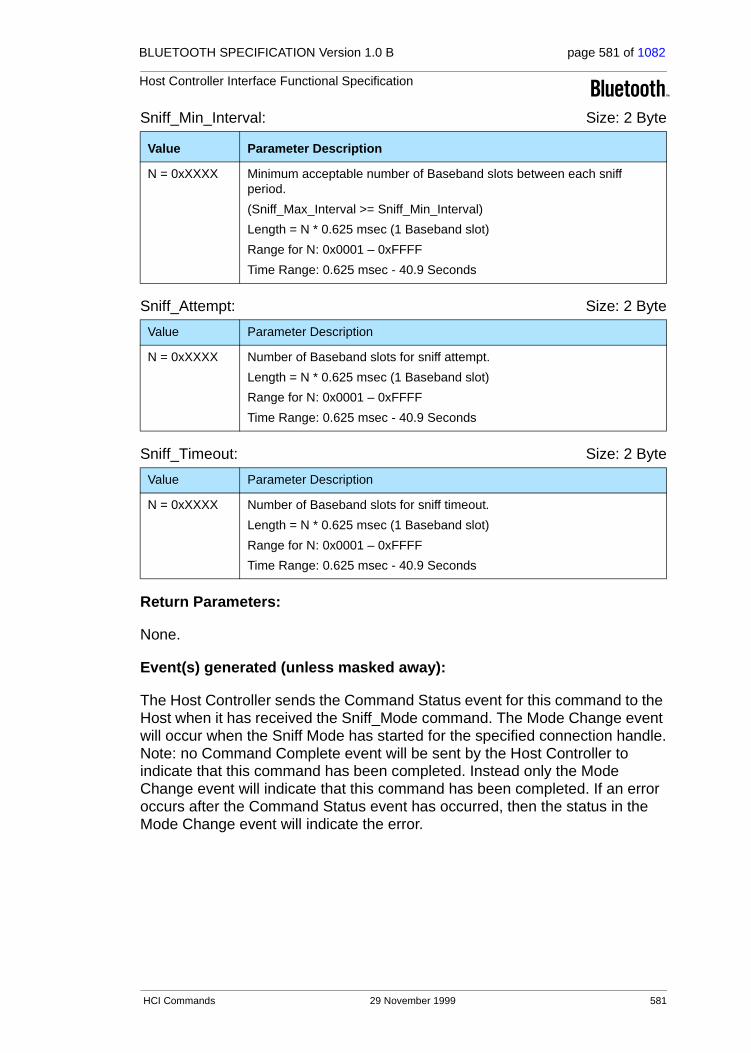
BLUETOOTH SPECIFICATION Version 1.0 B page 581 of 1082
Host Controller Interface Functional Specification
Sniff_Min_Interval: Size: 2 Byte
Sniff_Attempt: Size: 2 Byte
Sniff_Timeout: Size: 2 Byte
Return Parameters:
None.
Event(s) generated (unless masked away):
The Host Controller sends the Command Status event for this command to the Host when it has received the Sniff_Mode command. The Mode Change event will occur when the Sniff Mode has started for the specified connection handle.Note: no Command Complete event will be sent by the Host Controller to indicate that this command has been completed. Instead only the Mode Change event will indicate that this command has been completed. If an error occurs after the Command Status event has occurred, then the status in the Mode Change event will indicate the error.
Value Parameter Description
N = 0xXXXX Minimum acceptable number of Baseband slots between each sniff period.
(Sniff_Max_Interval >= Sniff_Min_Interval)
Length = N * 0.625 msec (1 Baseband slot)
Range for N: 0x0001 – 0xFFFF
Time Range: 0.625 msec - 40.9 Seconds
Value Parameter Description
N = 0xXXXX Number of Baseband slots for sniff attempt.
Length = N * 0.625 msec (1 Baseband slot)
Range for N: 0x0001 – 0xFFFF
Time Range: 0.625 msec - 40.9 Seconds
Value Parameter Description
N = 0xXXXX Number of Baseband slots for sniff timeout.
Length = N * 0.625 msec (1 Baseband slot)
Range for N: 0x0001 – 0xFFFF
Time Range: 0.625 msec - 40.9 Seconds
HCI Commands 29 November 1999 581

BLUETOOTH SPECIFICATION Version 1.0 B page 582 of 1082
Host Controller Interface Functional Specification
4.6.3 Exit_Sniff_Mode
Description:
The Exit_Sniff_Mode command is used to end the sniff mode for a connection handle, which is currently in sniff mode. The Link Manager will determine and issue the appropriate LMP commands to remove the sniff mode for the associ-ated Connection Handle. Note: in addition, the connection handle cannot be one of SCO link type.
Command Parameters:
Connection_Handle: Size: 2 Bytes (12 Bits meaningful)
Return Parameters:
None.
Event(s) generated (unless masked away):
A Command Status event for this command will occur when Host Controller has received the Exit_Sniff_Mode command. The Mode Change event will occur when the Sniff Mode has ended for the specified connection handle.Note: no Command Complete event will be sent by the Host Controller to indicate that this command has been completed. Instead, only the Mode Change event will indicate that this command has been completed.
Command OCF Command Parameters Return Parameters
HCI_Exit_Sniff_Mode 0x0004 Connection_Handle
Value Parameter Description
0xXXXX Connection Handle to be used to identify a connection.
Range: 0x0000-0x0EFF (0x0F00 - 0x0FFF Reserved for future use)
582 29 November 1999 HCI Commands

BLUETOOTH SPECIFICATION Version 1.0 B page 583 of 1082
Host Controller Interface Functional Specification
4.6.4 Park_Mode
Description:
The Park Mode command is used to alter the behavior of the Link Manager, and have the LM place the baseband connection associated by the specified Connection Handle into the Park mode. The Connection_Handle command parameter is used to identify which connection is to be placed in Park mode. The Connection_Handle must be a Connection_Handle for an ACL connection. The Beacon Interval command parameters specify the acceptable length of the interval between beacons. However, the remote device may request shorter interval. The Beacon_Max_Interval parameter specifies the acceptable longest length of the interval between beacons. The Beacon_Min_Interval parameter specifies the acceptable shortest length of the interval between beacons. Therefore, the Beacon Min Interval cannot be greater than the Beacon Max Interval. The Host Controller will return the actual Beacon interval in the Inter-val parameter of the Mode Change event, if the command is successful. This command enables the Host to support a low-power policy for itself or several other Bluetooth devices, allows the devices to enter Inquiry Scan, Page Scan, provides support for large number of Bluetooth Devices in a single piconet, and a number of other possible activities.
Command Parameters:
Connection_Handle: Size: 2 Bytes (12 Bits meaningful)
Beacon_Max_Interval: Size: 2 Bytes
Command OCF Command Parameters Return Parameters
HCI_Park_Mode 0x0005 Connection_Handle,
Beacon_Max_Interval,
Beacon_Min_Interval
Value Parameter Description
0xXXXX Connection Handle to be used to identify a connection.
Range: 0x0000-0x0EFF (0x0F00 - 0x0FFF Reserved for future use)
Value Parameter Description
N = 0xXXXX Maximum acceptable number of Baseband slots between consecutive beacons.
Interval Length = N * 0.625 msec (1 Baseband slot)
Range for N: 0x0001 – 0xFFFF
Time Range: 0.625 msec - 40.9 Seconds
HCI Commands 29 November 1999 583

BLUETOOTH SPECIFICATION Version 1.0 B page 584 of 1082
Host Controller Interface Functional Specification
Beacon_Min_Interval Size: 2 Bytes
Return Parameters:
None.
Event(s) generated (unless masked away):
The Host Controller sends the Command Status event for this command to the Host when it has received the Park_Mode command. The Mode Change event will occur when the Park Mode has started for the specified connection handle.Note: no Command Complete event will be sent by the Host Controller to indicate that this command has been completed. Instead, only the Mode Change event will indicate that this command has been completed. If an error occurs after the Command Status event has occurred, then the status in the Mode Change event will indicate the error.
Value Parameter Description
N = 0xXXXX Minimum acceptable number of Baseband slots between consecutive beacons
Interval Length = N * 0.625 msec (1 Baseband slot)
Range for N: 0x0001 – 0xFFFF
Time Range: 0.625 msec - 40.9 Seconds
584 29 November 1999 HCI Commands

BLUETOOTH SPECIFICATION Version 1.0 B page 585 of 1082
Host Controller Interface Functional Specification
4.6.5 Exit_Park_Mode
Description:
The Exit_Park_Mode command is used to switch the Bluetooth device from park mode back to active mode. This command may only be issued when the device associated with the specified Connection Handle is in Park Mode. The Connection_Handle must be a Connection_Handle for an ACL connection. This function does not complete immediately.
Command Parameters:
Connection_Handle: Size: 2 Bytes (12 Bits meaningful)
Return Parameters:
None.
Event(s) generated (unless masked away):
A Command Status event for this command will occur when the Host Controller has received the Exit_Park_Mode command. The Mode Change event will occur when the Park Mode has ended for the specified connection handle.Note: no Command Complete event will be sent by the Host Controller to indicate that this command has been completed. Instead, only the Mode Change event will indicate that this command has been completed.
Command OCF Command Parameters Return Parameters
HCI_Exit_Park_Mode 0x0006 Connection_Handle
Value Parameter Description
0xXXXX Connection Handle to be used to identify a connection.
Range: 0x0000-0x0EFF (0x0F00 - 0x0FFF Reserved for future use)
HCI Commands 29 November 1999 585

BLUETOOTH SPECIFICATION Version 1.0 B page 586 of 1082
Host Controller Interface Functional Specification
4.6.6 QoS_Setup
Description:
The QoS_Setup command is used to specify Quality of Service parameters for a connection handle. The Connection_Handle must be a Connection_Handle for an ACL connection. These QoS parameter are the same parameters as L2CAP QoS. For more detail see “Logical Link Control and Adaptation Protocol Specification” on page 245. This allows the Link Manager to have all of the information about what the Host is requesting for each connection. The LM will determine if the QoS parameters can be met. Bluetooth devices that are both slaves and masters can use this command. When a device is a slave, this com-mand will trigger an LMP request to the master to provide the slave with the specified QoS as determined by the LM. When a device is a master, this com-mand is used to request a slave device to accept the specified QoS as deter-mined by the LM of the master. The Connection_Handle command parameter is used to identify for which connection the QoS request is requested.
Command Parameters:
Connection_Handle: Size: 2 Bytes (12 Bits meaningful)
Flags: Size: 1 Byte
Command OCFCommand Parameters Return Parameters
HCI_QoS_Setup 0x0007 Connection_Handle,
Flags,
Service_Type,
Token_Rate,
Peak_Bandwidth,
Latency,
Delay_Variation
Value Parameter Description
0xXXXX Connection Handle to be used to identify which connection for the QoS Setup.
Range: 0x0000-0x0EFF (0x0F00 - 0x0FFF Reserved for future use)
Value Parameter Description
0x00 – 0xFF Reserved for Future Use.
586 29 November 1999 HCI Commands
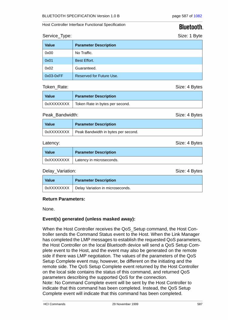
BLUETOOTH SPECIFICATION Version 1.0 B page 587 of 1082
Host Controller Interface Functional Specification
Service_Type: Size: 1 Byte
Token_Rate: Size: 4 Bytes
Peak_Bandwidth: Size: 4 Bytes
Latency: Size: 4 Bytes
Delay_Variation: Size: 4 Bytes
Return Parameters:
None.
Event(s) generated (unless masked away):
When the Host Controller receives the QoS_Setup command, the Host Con-troller sends the Command Status event to the Host. When the Link Manager has completed the LMP messages to establish the requested QoS parameters, the Host Controller on the local Bluetooth device will send a QoS Setup Com-plete event to the Host, and the event may also be generated on the remote side if there was LMP negotiation. The values of the parameters of the QoS Setup Complete event may, however, be different on the initiating and the remote side. The QoS Setup Complete event returned by the Host Controller on the local side contains the status of this command, and returned QoS parameters describing the supported QoS for the connection. Note: No Command Complete event will be sent by the Host Controller to indicate that this command has been completed. Instead, the QoS Setup Complete event will indicate that this command has been completed.
Value Parameter Description
0x00 No Traffic.
0x01 Best Effort.
0x02 Guaranteed.
0x03-0xFF Reserved for Future Use.
Value Parameter Description
0xXXXXXXXX Token Rate in bytes per second.
Value Parameter Description
0xXXXXXXXX Peak Bandwidth in bytes per second.
Value Parameter Description
0xXXXXXXXX Latency in microseconds.
Value Parameter Description
0xXXXXXXXX Delay Variation in microseconds.
HCI Commands 29 November 1999 587
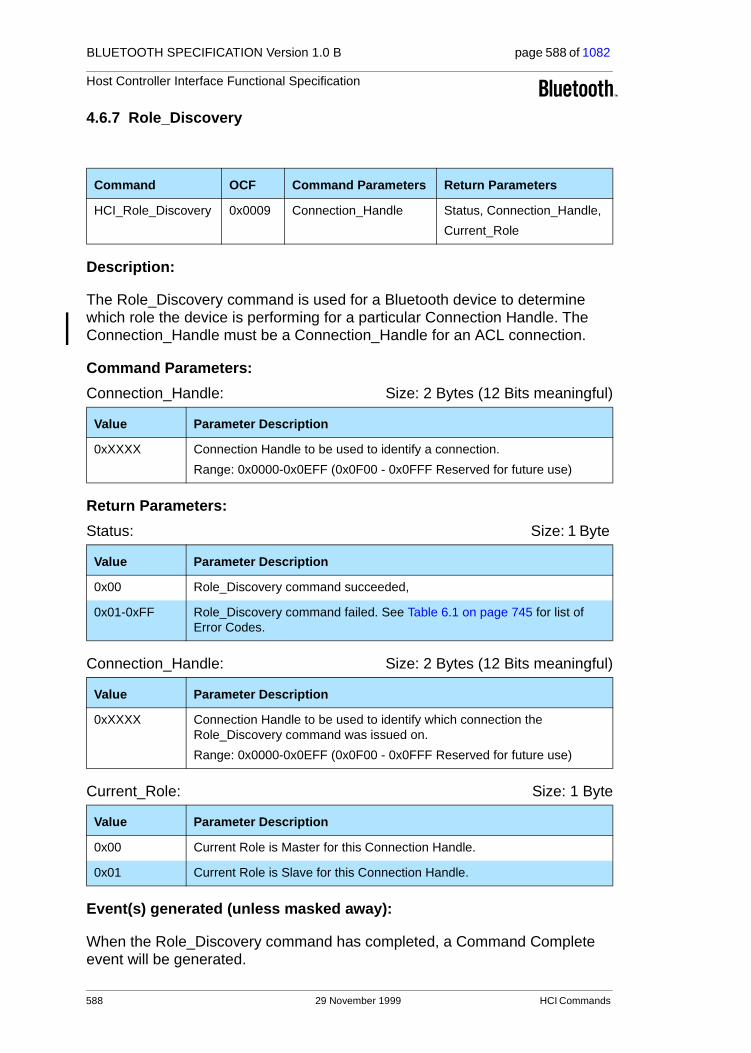
BLUETOOTH SPECIFICATION Version 1.0 B page 588 of 1082
Host Controller Interface Functional Specification
4.6.7 Role_Discovery
Description:
The Role_Discovery command is used for a Bluetooth device to determine which role the device is performing for a particular Connection Handle. The Connection_Handle must be a Connection_Handle for an ACL connection.
Command Parameters:
Connection_Handle: Size: 2 Bytes (12 Bits meaningful)
Return Parameters:
Status: Size: 1 Byte
Connection_Handle: Size: 2 Bytes (12 Bits meaningful)
Current_Role: Size: 1 Byte
Event(s) generated (unless masked away):
When the Role_Discovery command has completed, a Command Complete event will be generated.
Command OCF Command Parameters Return Parameters
HCI_Role_Discovery 0x0009 Connection_Handle Status, Connection_Handle,
Current_Role
Value Parameter Description
0xXXXX Connection Handle to be used to identify a connection.
Range: 0x0000-0x0EFF (0x0F00 - 0x0FFF Reserved for future use)
Value Parameter Description
0x00 Role_Discovery command succeeded,
0x01-0xFF Role_Discovery command failed. See Table 6.1 on page 745 for list of Error Codes.
Value Parameter Description
0xXXXX Connection Handle to be used to identify which connection the Role_Discovery command was issued on.
Range: 0x0000-0x0EFF (0x0F00 - 0x0FFF Reserved for future use)
Value Parameter Description
0x00 Current Role is Master for this Connection Handle.
0x01 Current Role is Slave for this Connection Handle.
588 29 November 1999 HCI Commands

BLUETOOTH SPECIFICATION Version 1.0 B page 589 of 1082
Host Controller Interface Functional Specification
4.6.8 Switch_Role
Description:
The Switch_Role command is used for a Bluetooth device to switch the current role the device is performing for a particular connection with another specified Bluetooth device. The BD_ADDR command parameter indicates for which con-nection the role switch is to be performed. The Role indicates the requested new role that the local device performs. Note: the BD_ADDR command parameter must specify a Bluetooth device for which a connection already exists.
Command Parameters:
BD_ADDR: Size: 6 Bytes
Role: Size: 1 Byte
Return Parameters:
None.
Event(s) generated (unless masked away):
A Command Status event for this command will occur when the Host Controller has received the Switch_Role command. When the role switch is performed, a Role Change event will occur to indicate that the roles have been changed, and will be communicated to both Hosts. Note: no Command Complete event will be sent by the Host Controller to indicate that this command has been completed. Instead, only the Role Change event will indicate that this command has been completed.
Command OCF Command Parameters Return Parameters
HCI_Switch_Role 0x000B BD_ADDR, Role
Value Parameter Description
0xXXXXXXXXXXXX
BD_ADDR for the connected device with which a role switch is to be performed.
Value Parameter Description
0x00 Change own Role to Master for this BD_ADDR.
0x01 Change own Role to Slave for this BD_ADDR.
HCI Commands 29 November 1999 589

BLUETOOTH SPECIFICATION Version 1.0 B page 590 of 1082
Host Controller Interface Functional Specification
4.6.9 Read_Link_Policy_Settings
Description:
This command will read the Link Policy setting for the specified Connection Handle. The Link_Policy_Settings parameter determines the behavior of the local Link Manager when it receives a request from a remote device or it deter-mines itself to change the master-slave role or to enter the hold, sniff, or park mode. The local Link Manager will automatically accept or reject such a request from the remote device, and may even autonomously request itself, depending on the value of the Link_Policy_Settings parameter for the corre-sponding Connection_Handle. When the value of the Link_Policy_Settings parameter is changed for a certain Connection_Handle, the new value will only be used for requests from a remote device or from the local Link Manager itself made after this command has been completed. The Connection_Handle must be a Connection_Handle for an ACL connection. By enabling each mode indi-vidually, the Host can choose any combination needed to support various modes of operation. Multiple LM policies may be specified for the Link_Policy_Settings parameter by performing a bitwise OR operation of the different activity types.
Command Parameters:
Connection_Handle: Size: 2 Bytes (12 Bits meaningful)
Return Parameters:
Status: Size: 1 Byte
Command OCF Command Parameters Return Parameters
HCI_Read_Link_Policy_Settings
0x000C Connection_Handle Status,
Connection_Handle
Link_Policy_Settings
Value Parameter Description
0xXXXX Connection Handle to be used to identify a connection.
Range: 0x0000-0x0EFF (0x0F00 - 0x0FFF Reserved for future use)
Value Parameter Description
0x00 Read_Link_Policy_Settings command succeeded.
0x01-0xFF Read_Link_Policy_Settings command failed. See Table 6.1 on page 745 for list of Error Codes.
590 29 November 1999 HCI Commands

BLUETOOTH SPECIFICATION Version 1.0 B page 591 of 1082
Host Controller Interface Functional Specification
Connection_Handle: Size: 2 Bytes (12 Bits meaningful)
Link_Policy_Settings Size: 2 Bytes
Event(s) generated (unless masked away):
When the Read_Link_Policy_Settings command has completed, a Command Complete event will be generated.
Value Parameter Description
0xXXXX Connection Handle to be used to identify a connection.
Range: 0x0000-0x0EFF (0x0F00 - 0x0FFF Reserved for future use)
Value Parameter Description
0x0000 Disable All LM Modes.
0x0001 Enable Master Slave Switch.
0x0002 Enable Hold Mode.
0x0004 Enable Sniff Mode.
0x0008 Enable Park Mode.
0x0010
–
0x8000
Reserved for Future Use.
HCI Commands 29 November 1999 591

BLUETOOTH SPECIFICATION Version 1.0 B page 592 of 1082
Host Controller Interface Functional Specification
4.6.10 Write_Link_Policy_Settings
Description:
This command will write the Link Policy setting for the specified Connection Handle. The Link_Policy_Settings parameter determines the behavior of the local Link Manager when it receives a request from a remote device or it deter-mines itself to change the master-slave role or to enter the hold, sniff, or park mode. The local Link Manager will automatically accept or reject such a request from the remote device, and may even autonomously request itself, depending on the value of the Link_Policy_Settings parameter for the corre-sponding Connection_Handle. When the value of the Link_Policy_Settings parameter is changed for a certain Connection_Handle, the new value will only be used for requests from a remote device or from the local Link Manager itself made after this command has been completed. The Connection_Handle must be a Connection_Handle for an ACL connection. By enabling each mode indi-vidually, the Host can choose any combination needed to support various modes of operation. Multiple LM policies may be specified for the Link_Policy_Settings parameter by performing a bitwise OR operation of the different activity types.
Command Parameters:
Connection_Handle: Size: 2 Bytes (12 Bits meaningful)
Command OCF Command Parameters Return Parameters
HCI_Write_Link_Policy_Settings
0x000D Connection_Handle,
Link_Policy_Settings
Status,
Connection_Handle
Value Parameter Description
0xXXXX Connection Handle to be used to identify a connection.
Range: 0x0000-0x0EFF (0x0F00 - 0x0FFF Reserved for future use)
592 29 November 1999 HCI Commands

BLUETOOTH SPECIFICATION Version 1.0 B page 593 of 1082
Host Controller Interface Functional Specification
Link_Policy_Settings Size: 2 Bytes
Return Parameters:
Status: Size: 1 Byte
Connection_Handle: Size: 2 Bytes (12 Bits meaningful)
Event(s) generated (unless masked away):
When the Write_Link_Policy_Settings command has completed, a Command Complete event will be generated.
Value Parameter Description
0x0000 Disable All LM Modes Default.
0x0001 Enable Master Slave Switch.
0x0002 Enable Hold Mode.
0x0004 Enable Sniff Mode.
0x0008 Enable Park Mode.
0x0010
–
0x8000
Reserved for Future Use.
Value Parameter Description
0x00 Write_Link_Policy_Settings command succeeded.
0x01-0xFF Write_Link_Policy_Settings command failed. See Table 6.1 on page 745 for list of Error Codes.
Value Parameter Description
0xXXXX Connection Handle to be used to identify a connection.
Range: 0x0000-0x0EFF (0x0F00 - 0x0FFF Reserved for future use)
HCI Commands 29 November 1999 593

BLUETOOTH SPECIFICATION Version 1.0 B page 594 of 1082
Host Controller Interface Functional Specification
4.7 HOST CONTROLLER & BASEBAND COMMANDS
The Host Controller & Baseband Commands provide access and control to various capabilities of the Bluetooth hardware. These parameters provide con-trol of Bluetooth devices and of the capabilities of the Host Controller, Link Manager, and Baseband. The host device can use these commands to modify the behavior of the local device. For the HCI Control and Baseband Com-mands, the OGF is defined as 0x03
Command Command Summary Description
Set_Event_Mask The Set_Event_Mask command is used to control which events are generated by the HCI for the Host.
Reset The Reset command will reset the Bluetooth Host Controller, Link Manager, and the radio module.
Set_Event_Filter The Set_Event_Filter command is used by the Host to specify different event filters. The Host may issue this command multiple times to request various conditions for the same type of event filter and for different types of event filters.
Flush The Flush command is used to discard all data that is currently pending for transmission in the Host Controller for the specified connection handle, even if there currently are chunks of data that belong to more than one L2CAP packet in the Host Controller.
Read_PIN_Type The Read_PIN_Type command is used for the Host to read the value that is specified to indi-cate whether the Host supports variable PIN or only fixed PINs.
Write_PIN_Type The Write_PIN_Type command is used for the Host to specify whether the Host supports vari-able PIN or only fixed PINs.
Create_New_Unit_Key The Create_New_Unit_Key command is used to create a new unit key.
Read_Stored_Link_Key The Read_Stored_Link_Key command pro-vides the ability to read one or more link keys stored in the Bluetooth Host Controller.
Write_Stored_Link_Key The Write_Stored_Link_Key command pro-vides the ability to write one or more link keys to be stored in the Bluetooth Host Controller.
594 29 November 1999 HCI Commands

BLUETOOTH SPECIFICATION Version 1.0 B page 595 of 1082
Host Controller Interface Functional Specification
Command Command Summary Description
Delete_Stored_Link_Key The Delete_Stored_Link_Key command pro-vides the ability to remove one or more of the link keys stored in the Bluetooth Host Control-ler.
Change_Local_Name The Change_Local_Name command provides the ability to modify the user-friendly name for the Bluetooth device.
Read_Local_Name The Read_Local_Name command provides the ability to read the stored user-friendly name for the Bluetooth device.
Read_Connection_Accept_Timeout The Read_Connection_Accept_Timeout com-mand will read the value for the Connection_Accept_Timeout configuration parameter, which allows the Bluetooth hardware to automatically deny a connection request after a specified period has occurred, and to refuse a new con-nection.
Write_Connection_Accept_Timeout The Write_Connection_Accept_Timeout will write the value for the Connection_Accept_Timeout configuration parameter, which allows the Bluetooth hardware to automatically deny a connection request after a specified period has occurred, and to refuse a new connection.
Read_Page_Timeout The Read_Page_Timeout command will read the value for the Page_Reply_Timeout configu-ration parameter, which allows the Bluetooth hardware to define the amount of time a con-nection request will wait for the remote device to respond before the local device returns a connection failure.
Write_Page_Timeout The Write_Page_Timeout command will write the value for the Page_Reply_Timeout configu-ration parameter, which allows the Bluetooth hardware to define the amount of time a con-nection request will wait for the remote device to respond before the local device returns a connection failure.
Read_Scan_Enable The Read_Scan_Enable command will read the value for the Scan_Enable configuration param-eter, which controls whether or not the Blue-tooth device will periodically scan for page attempts and/or inquiry requests from other Bluetooth devices.
HCI Commands 29 November 1999 595

BLUETOOTH SPECIFICATION Version 1.0 B page 596 of 1082
Host Controller Interface Functional Specification
Write_Scan_Enable The Write_Scan_Enable command will write the value for the Scan_Enable configuration parameter, which controls whether or not the Bluetooth device will periodically scan for page attempts and/or inquiry requests from other Bluetooth devices.
Read_Page_Scan_Activity The Read_Page_Scan_Activity command will read the values for the Page_Scan_Interval and Page_Scan_Window configuration parame-ters. Page_Scan_Interval defines the amount of time between consecutive page scans. Page_Scan_Window defines the duration of the page scan.
Write_Page_Scan_Activity The Write_Page_Scan_Activity command will write the value for Page_Scan_Interval and_Page_Scan_Window configuration parame-ters. Page_Scan_Interval defines the amount of time between consecutive page scans. Page_Scan_Window defines the duration of the page scan.
Read_Inquiry_Scan_Activity The Read_Inquiry_Scan_Activity command will read the value for Inquiry_Scan_Interval and Inquiry_Scan_Window configuration parame-ters. Inquiry_Scan_Interval defines the amount of time between consecutive inquiry scans. Inquiry_Scan_Window defines the amount of time for the duration of the inquiry scan.
Write_Inquiry_Scan_Activity The Write_Inquiry_Scan_Activity command will write the value for Inquiry_Scan_Interval and Inquiry_Scan_Window configuration parame-ters. Inquiry_Scan_Interval defines the amount of time between consecutive inquiry scans. Inquiry_Scan_Window defines the amount of time for the duration of the inquiry scan.
Read_Authentication_Enable The Read_Authentication_Enable command will read the value for the Authentication_Enable parameter, which controls whether the Bluetooth device will require authentication for each connection with other Bluetooth devices.
Write_Authentication_Enable The Write_Authentication_Enable command will write the value for the Authentication_Enable parameter, which controls whether the Bluetooth device will require authentication for each connection with other Bluetooth devices.
Read_Encryption_Mode The Read_Encryption_Mode command will read the value for the Encryption_Mode param-eter, which controls whether the Bluetooth device will require encryption for each connection with other Bluetooth devices.
Command Command Summary Description
596 29 November 1999 HCI Commands

BLUETOOTH SPECIFICATION Version 1.0 B page 597 of 1082
Host Controller Interface Functional Specification
Write_Encryption_Mode The Write_Encryption_Mode command will write the value for the Encryption_Mode param-eter, which controls whether the Bluetooth device will require encryption for each connection with other Bluetooth devices.
Read_Class_of_Device The Read_Class_of_Device command will read the value for the Class_of_Device parameter, which is used to indicate its capabilities to other devices.
Write_Class_of_Device The Write_Class_of_Device command will write the value for the Class_of_Device parameter, which is used to indicate its capabilities to other devices.
Read_Voice_Setting The Read_Voice_Setting command will read the values for the Voice_Setting parameter, which controls all the various settings for the voice connections.
Write_Voice_Setting The Write_Voice_Setting command will write the values for the Voice_Setting parameter, which controls all the various settings for the voice connections.
Read_Automatic_Flush_Timeout The Read_Automatic_Flush_Timeout will read the value for the Flush_Timeout parameter for the specified connection handle. The Flush_Timeout parameter is only used for ACL con-nections.
Write_Automatic_Flush_Timeout The Write_Automatic_Flush_Timeout will write the value for the Flush_Timeout parameter for the specified connection handle. The Flush_Timeout parameter is only used for ACL con-nections.
Read_Num_Broadcast_Retransmissions The Read_Num_Broadcast_Retransmissions command will read the parameter value for the Number of Broadcast Retransmissions for the device. Broadcast packets are not acknowl-edged and are unreliable. This parameter is used to increase the reliability of a broadcast message by retransmitting the broadcast mes-sage multiple times.
Write_Num_Broadcast_Retransmissions The Write_Num_Broadcast_Retransmissions command will write the parameter value for the Number of Broadcast Retransmissions for the device. Broadcast packets are not acknowl-edged and are unreliable. This parameter is used to increase the reliability of a broadcast message by retransmitting the broadcast mes-sage multiple times.
Command Command Summary Description
HCI Commands 29 November 1999 597

BLUETOOTH SPECIFICATION Version 1.0 B page 598 of 1082
Host Controller Interface Functional Specification
Read_Hold_Mode_Activity The Read_Hold_Mode_Activity command will read the value for the Hold_Mode_Activity parameter. This value is used to determine what activity the device should do when it is in hold mode.
Write_Hold_Mode_Activity The Write_Hold_Mode_Activity command will write the value for the Hold_Mode_Activity parameter. This value is used to determine what activity the device should do when it is in hold mode.
Read_Transmit_Power_Level The Read_Transmit_Power_Level command will read the values for the Transmit_Power_Level parameter for the specified Connection Handle.
Read_SCO_Flow_Control_Enable The Read_SCO_Flow_Control_Enable com-mand provides the ability to read the SCO_Flow_Control_Enable setting. By using this setting, the Host can decide if the Host Controller will send Number Of Completed Packets events for SCO Connection Handles.
Write_SCO_Flow_Control_Enable The Write_SCO_Flow_Control_Enable com-mand provides the ability to write the SCO_Flow_Control_Enable setting. By using this setting, the Host can decide if the Host Controller will send Number Of Completed Packets events for SCO Connection Handles.
Set_Host_Controller_To_Host_Flow_Control
The Set_Host_Controller_To_Host_Flow_Control command is used by the Host to turn flow control on or off in the direction from the Host Controller to the Host.
Host_Buffer_Size The Host_Buffer_Size command is used by the Host to notify the Host Controller about its buffer sizes for ACL and SCO data. The Host Controller will segment the data to be transmit-ted from the Host Controller to the Host, so that data contained in HCI Data Packets will not exceed these sizes.
Host_Number_Of_Completed_Packets The Host_Number_Of_Completed_Packets command is used by the Host to indicate to the Host Controller when the Host is ready to receive more HCI packets for any connection handle.
Read_Link_Supervision_Timeout The Read_Link_Supervision_Timeout command will read the value for the Link_Supervision_Timeout parameter for the device. This parameter is used by the master or slave Bluetooth device to monitor link loss.
Command Command Summary Description
598 29 November 1999 HCI Commands

BLUETOOTH SPECIFICATION Version 1.0 B page 599 of 1082
Host Controller Interface Functional Specification
Write Link_Supervision_Timeout The Write Link_Supervision_Timeout command will write the value for the Link_Supervision_Timeout parameter for the device. This parame-ter is used by the master or slave Bluetooth device to monitor link loss.
Read_Number_Of_Supported_IAC The Read_Number_Of_Supported_IAC command will read the value for the number of Inquiry Access Codes (IAC) that the local Bluetooth device can simultaneously listen for during an Inquiry Scan.
Read_Current_IAC_LAP The Read_Current_IAC_LAP command will read the LAP(s) used to create the Inquiry Access Codes (IAC) that the local Bluetooth device is simultaneously scanning for during Inquiry Scans.
Write_Current_IAC_LAP The Write_Current_IAC_LAP will write the LAP(s) used to create the Inquiry Access Codes (IAC) that the local Bluetooth device is simultaneously scanning for during Inquiry Scans.
Read_Page_Scan_Period_Mode The Read_Page_Scan_Period_Mode com-mand is used to read the mandatory Page_Scan_Period_Mode of the local Bluetooth device.
Write_Page_Scan_Period_Mode The Write_Page_Scan_Period_Mode com-mand is used to write the mandatory Page_Scan_Period_Mode of the local Bluetooth device.
Read_Page_Scan_Mode The Read_Page_Scan_Mode command is used to read the default Page_Scan_Mode of the local Bluetooth device.
Write_Page_Scan_Mode The Write_Page_Scan_Mode command is used to write the default Page_Scan_Mode of the local Bluetooth device.
Command Command Summary Description
HCI Commands 29 November 1999 599
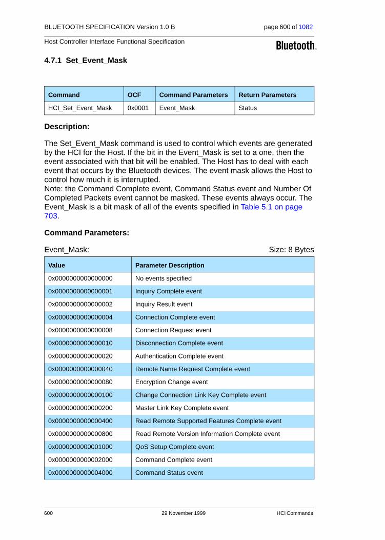
BLUETOOTH SPECIFICATION Version 1.0 B page 600 of 1082
Host Controller Interface Functional Specification
4.7.1 Set_Event_Mask
Description:
The Set_Event_Mask command is used to control which events are generated by the HCI for the Host. If the bit in the Event_Mask is set to a one, then the event associated with that bit will be enabled. The Host has to deal with each event that occurs by the Bluetooth devices. The event mask allows the Host to control how much it is interrupted.Note: the Command Complete event, Command Status event and Number Of Completed Packets event cannot be masked. These events always occur. The Event_Mask is a bit mask of all of the events specified in Table 5.1 on page 703.
Command Parameters:
Event_Mask: Size: 8 Bytes
Command OCF Command Parameters Return Parameters
HCI_Set_Event_Mask 0x0001 Event_Mask Status
Value Parameter Description
0x0000000000000000 No events specified
0x0000000000000001 Inquiry Complete event
0x0000000000000002 Inquiry Result event
0x0000000000000004 Connection Complete event
0x0000000000000008 Connection Request event
0x0000000000000010 Disconnection Complete event
0x0000000000000020 Authentication Complete event
0x0000000000000040 Remote Name Request Complete event
0x0000000000000080 Encryption Change event
0x0000000000000100 Change Connection Link Key Complete event
0x0000000000000200 Master Link Key Complete event
0x0000000000000400 Read Remote Supported Features Complete event
0x0000000000000800 Read Remote Version Information Complete event
0x0000000000001000 QoS Setup Complete event
0x0000000000002000 Command Complete event
0x0000000000004000 Command Status event
600 29 November 1999 HCI Commands
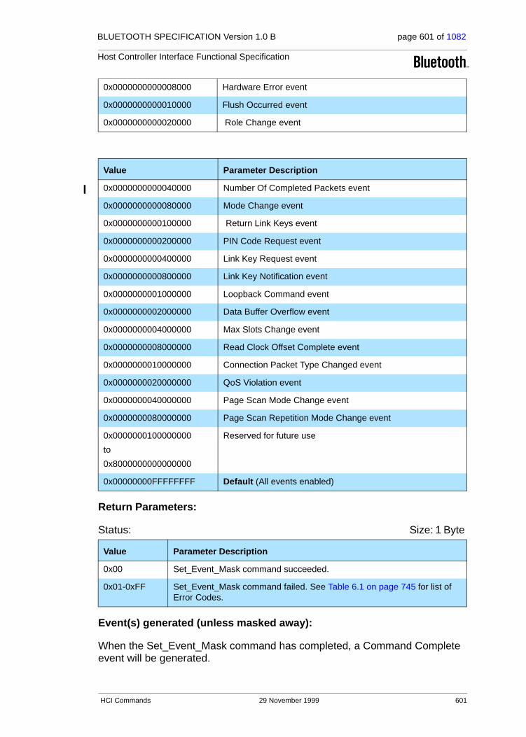
BLUETOOTH SPECIFICATION Version 1.0 B page 601 of 1082
Host Controller Interface Functional Specification
Return Parameters:
Status: Size: 1 Byte
Event(s) generated (unless masked away):
When the Set_Event_Mask command has completed, a Command Complete event will be generated.
0x0000000000008000 Hardware Error event
0x0000000000010000 Flush Occurred event
0x0000000000020000 Role Change event
Value Parameter Description
0x0000000000040000 Number Of Completed Packets event
0x0000000000080000 Mode Change event
0x0000000000100000 Return Link Keys event
0x0000000000200000 PIN Code Request event
0x0000000000400000 Link Key Request event
0x0000000000800000 Link Key Notification event
0x0000000001000000 Loopback Command event
0x0000000002000000 Data Buffer Overflow event
0x0000000004000000 Max Slots Change event
0x0000000008000000 Read Clock Offset Complete event
0x0000000010000000 Connection Packet Type Changed event
0x0000000020000000 QoS Violation event
0x0000000040000000 Page Scan Mode Change event
0x0000000080000000 Page Scan Repetition Mode Change event
0x0000000100000000
to
0x8000000000000000
Reserved for future use
0x00000000FFFFFFFF Default (All events enabled)
Value Parameter Description
0x00 Set_Event_Mask command succeeded.
0x01-0xFF Set_Event_Mask command failed. See Table 6.1 on page 745 for list of Error Codes.
HCI Commands 29 November 1999 601

BLUETOOTH SPECIFICATION Version 1.0 B page 602 of 1082
Host Controller Interface Functional Specification
4.7.2 Reset
Description:
The Reset command will reset the Bluetooth Host Controller, Link Manager, and the radio module. The current operational state will be lost, and all queued packets will be lost. After the reset is completed, the Bluetooth device will enter standby mode. Note: after the reset has completed, the Host Controller will automatically revert to the default values for the parameters for which default values are defined in this specification.
Command Parameters:
None.
Return Parameters:
Status: Size: 1 Byte
Event(s) generated (unless masked away):
Before the Reset command will be executed, a Command Complete event needs to be returned to indicate to the Host that the Reset command was received and will be executed.
Command OCF Command Parameters Return Parameters
HCI_Reset 0x0003 Status
Value Parameter Description
0x00 Reset command succeeded, was received and will be executed.
0x01-0xFF Reset command failed. See Table 6.1 on page 745 for list of Error Codes.
602 29 November 1999 HCI Commands

BLUETOOTH SPECIFICATION Version 1.0 B page 603 of 1082
Host Controller Interface Functional Specification
4.7.3 Set_Event_Filter
Description:
The Set_Event_Filter command is used by the Host to specify different event filters. The Host may issue this command multiple times to request various conditions for the same type of event filter and for different types of event fil-ters. The event filters are used by the Host to specify items of interest, which allow the Host Controller to send only events which interest the Host. Only some of the events have event filters. By default (before this command has been issued after power-on or Reset) no filters are set, and the Auto_Accept_Flag is off (incoming connections are not automatically accepted). An event filter is added each time this command is sent from the Host and the Filter_Condition_Type is not equal to 0x00. (The old event filters will not be overwritten). To clear all event filters, the Filter_Type = 0x00 is used. The Auto_Accept_Flag will then be set to off.
To clear event filters for only a certain Filter_Type, the Filter_Condition_Type = 0x00 is used. The Inquiry Result filter allows the Host Controller to filter out Inquiry Result events. The Inquiry Result filter allows the Host to specify that the Host Controller only sends Inquiry Results to the Host if the Inquiry Result event meets one of the specified conditions set by the Host. For the Inquiry Result filter, the Host can specify one or more of the following Filter Condition Types:
1. A new device responded to the Inquiry process
2. A device with a specific Class of Device responded to the Inquiry process
3. A device with a specific BD_ADDR responded to the Inquiry process
The Inquiry Result filter is used in conjunction with the Inquiry and Periodic Inquiry command. The Connection Setup filter allows the Host to specify that the Host Controller only sends a Connection Complete or Connection Request event to the Host if the event meets one of the specified conditions set by the Host. For the Connection Setup filter, the Host can specify one or more of the following Filter Condition Types:
1. Allow Connections from all devices
2. Allow Connections from a device with a specific Class of Device
3. Allow Connections from a device with a specific BD_ADDR
Command OCF Command Parameters Return Parameters
HCI_Set_Event_Filter 0x0005 Filter_Type,
Filter_Condition_Type,
Condition
Status
HCI Commands 29 November 1999 603

BLUETOOTH SPECIFICATION Version 1.0 B page 604 of 1082
Host Controller Interface Functional Specification
For each of these conditions, an Auto_Accept_Flag parameter allows the Host to specify what action should be done when the condition is met. The Auto_Accept_Flag allows the Host to specify if the incoming connection should be auto accepted (in which case the Host Controller will send the Connection Complete event to the Host when the connection is completed) or if the Host should make the decision (in which case the Host Controller will send the Con-nection Request event to the Host, to elicit a decision on the connection).
The Connection Setup filter is used in conjunction with the Read/Write_Scan_Enable commands. If the local device is in the process of a page scan, and is paged by another device which meets one on the conditions set by the Host, and the Auto_Accept_Flag is off for this device, then a Connection Request event will be sent to the Host by the Host Controller. A Connection Complete event will be sent later on after the Host has responded to the incom-ing connection attempt. In this same example, if the Auto_Accept_Flag is on, then a Connection Complete event will be sent to the Host by the Host Control-ler. (No Connection Request event will be sent in that case.)
The Host Controller will store these filters in volatile memory until the Host clears the event filters using the Set_Event_Filter command or until the Reset command is issued. The number of event filters the Host Controller can store is implementation dependent. If the Host tries to set more filters than the Host Controller can store, the Host Controller will return the "Memory Full" error code and the filter will not be installed.Note: the Clear All Filters has no Filter Condition Types or Conditions. Note: In the condition that a connection is auto accepted, a Link Key Request event and possibly also a PIN Code Request event and a Link Key Notification event could be sent to the Host by the Host Controller before the Connection Complete event is sent.
If there is a contradiction between event filters, the latest set event filter will override older ones. An example is an incoming connection attempt where more than one Connection Setup filter matches the incoming connection attempt, but the Auto-Accept_Flag has different values in the different filters.
604 29 November 1999 HCI Commands

BLUETOOTH SPECIFICATION Version 1.0 B page 605 of 1082
Host Controller Interface Functional Specification
Command Parameters:
Filter_Type: Size: 1 Byte
Filter Condition Types: For each Filter Type one or more Filter Condition types exists.
Inquiry_Result_Filter_Condition_Type: Size: 1 Byte
Connection_Setup_Filter_Condition_Type: Size: 1 Byte
Condition: For each Filter Condition Type defined for the Inquiry Result Filter and the Connection Setup Filter, zero or more Condition parameters are required – depending on the filter condition type and filter type.
Condition for Inquiry_Result_Filter_Condition_Type = 0x00
Condition: Size: 0 Byte
Value Parameter Description
0x00 Clear All Filters (Note: In this case, the Filter_Condition_type and Condi-tion parameters should not be given, they should have a length of 0 bytes. Filter_Type should be the only parameter.)
0x01 Inquiry Result.
0x02 Connection Setup.
0x03-0xFF Reserved for Future Use.
Value Parameter Description
0x00 A new device responded to the Inquiry process.(Note: A device may be reported to the Host in an Inquiry Result event more than once during an inquiry or inquiry period depending on the implementation, see description in Section 4.5.1 on page 542 and Section 4.5.3 on page 545)
0x01 A device with a specific Class of Device responded to the Inquiry process.
0x02 A device with a specific BD_ADDR responded to the Inquiry process.
0x03-0xFF Reserved for Future Use
Value Parameter Description
0x00 Allow Connections from all devices.
0x01 Allow Connections from a device with a specific Class of Device.
0x02 Allow Connections from a device with a specific BD_ADDR.
0x03-0xFF Reserved for Future Use.
Value Parameter Description
The Condition parameter is not used.
HCI Commands 29 November 1999 605

BLUETOOTH SPECIFICATION Version 1.0 B page 606 of 1082
Host Controller Interface Functional Specification
Condition for Inquiry_Result_Filter_Condition_Type = 0x01
Condition:
Size: 6 Bytes
Class_of_Device: Size: 3 Bytes
Class_of_Device_Mask: Size: 3 Bytes
Condition for Inquiry_Result_Filter_Condition_Type = 0x02
Condition:
Size: 6 Bytes
BD_ADDR: Size: 6 Bytes
Condition for Connection_Setup_Filter_Condition_Type = 0x00
Condition:
Size: 1 Byte
Auto_Accept_Flag: Size:1 Byte
Value Parameter Description
0x000000 Default, Return All Devices.
0xXXXXXX Class of Device of Interest.
Value Parameter Description
0xXXXXXX Bit Mask used to determine which bits of the Class of Device parameter are ‘don’t care’. Zero-value bits in the mask indicate the ‘don’t care’ bits of the Class of Device.
Value Parameter Description
0xXXXXXXXXXXXX
BD_ADDR of the Device of Interest
Value Parameter Description
0x01 Do NOT Auto accept the connection.
0x02 Do Auto accept the connection.
0x03 – 0xFF Reserved for future use.
606 29 November 1999 HCI Commands

BLUETOOTH SPECIFICATION Version 1.0 B page 607 of 1082
Host Controller Interface Functional Specification
Condition for Connection_Setup_Filter_Condition_Type = 0x01
Condition:
Size: 7 Bytes
Class_of_Device: Size: 3 Bytes
Class_of_Device_Mask: Size: 3 Bytes
Auto_Accept_Flag: Size: 1 Byte
Condition for Connection_Setup_Filter_Condition_Type = 0x02
Condition:
Size: 7 Bytes
BD_ADDR: Size: 6 Bytes
Auto_Accept_Flag: Size: 1 Byte
Value Parameter Description
0x000000 Default, Return All Devices.
0xXXXXXX Class of Device of Interest.
Value Parameter Description
0xXXXXXX Bit Mask used to determine which bits of the Class of Device parameter are ‘don’t care’. Zero-value bits in the mask indicate the ‘don’t care’ bits of the Class of Device.
Value Parameter Description
0x01 Do NOT Auto accept the connection.
0x02 Do Auto accept the connection.
0x03 – 0xFF Reserved for future use.
Value Parameter Description
0xXXXXXXXXXXXX
BD_ADDR of the Device of Interest.
Value Parameter Description
0x01 Do NOT Auto accept the connection.
0x02 Do Auto accept the connection.
0x03 – 0xFF Reserved for future use.
HCI Commands 29 November 1999 607

BLUETOOTH SPECIFICATION Version 1.0 B page 608 of 1082
Host Controller Interface Functional Specification
Return Parameters:
Status: Size: 1 Byte
Event(s) generated (unless masked away):
A Command Complete event for this command will occur when the Host Con-troller has enabled the filtering of events. When one of the conditions are met, a specific event will occur.
Value Parameter Description
0x00 Set_Event_Filter command succeeded.
0x01-0xFF Set_Event_Filter command failed. See Table 6.1 on page 745 for list of Error Codes.
608 29 November 1999 HCI Commands

BLUETOOTH SPECIFICATION Version 1.0 B page 609 of 1082
Host Controller Interface Functional Specification
4.7.4 Flush
Description:
The Flush command is used to discard all data that is currently pending for transmission in the Host Controller for the specified connection handle, even if there currently are chunks of data that belong to more than one L2CAP packet in the Host Controller. After this, all data that is sent to the Host Controller for the same connection handle will be discarded by the Host Controller until an HCI Data Packet with the start Packet_Boundary_Flag (0x02) is received. When this happens, a new transmission attempt can be made. This command will allow higher-level software to control how long the baseband should try to retransmit a baseband packet for a connection handle before all data that is currently pending for transmission in the Host Controller should be flushed. Note that the Flush command is used for ACL connections ONLY. In addition to the Flush command, the automatic flush timers (see section 4.7.31 on page 647) can be used to automatically flush the L2CAP packet that is currently being transmitted after the specified flush timer has expired.
Command Parameters:
Connection_Handle: Size: 2 Bytes (12 Bits meaningful)
Return Parameters:
Status: Size: 1 Byte
Connection_Handle: Size: 2 Bytes (12 Bits meaningful)
Command OCF Command Parameters Return Parameters
HCI_Flush 0x0008 Connection_Handle Status, Connection_Handle
Value Parameter Description
0xXXXX Connection Handle to be used to identify which connection to flush.
Range: 0x0000-0x0EFF (0x0F00 - 0x0FFF Reserved for future use)
Value Parameter Description
0x00 Flush command succeeded.
0x01-0xFF Flush command failed. See Table 6.1 on page 745 for list of Error Codes.
Value Parameter Description
0xXXXX Connection Handle to be used to identify which connection the flush com-mand was issued on.
Range: 0x0000-0x0EFF (0x0F00 - 0x0FFF Reserved for future use)
HCI Commands 29 November 1999 609

BLUETOOTH SPECIFICATION Version 1.0 B page 610 of 1082
Host Controller Interface Functional Specification
Event(s) generated (unless masked away):
The Flush Occurred event will occur once the flush is completed. A Flush Occurred event could be from an automatic Flush or could be cause by the Host issuing the Flush command. When the Flush command has completed, a Command Complete event will be generated, to indicate that the Host caused the Flush.
610 29 November 1999 HCI Commands
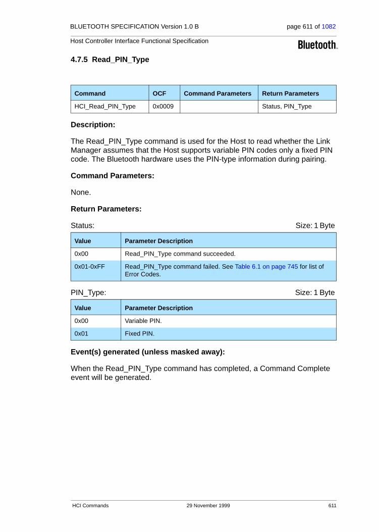
BLUETOOTH SPECIFICATION Version 1.0 B page 611 of 1082
Host Controller Interface Functional Specification
4.7.5 Read_PIN_Type
Description:
The Read_PIN_Type command is used for the Host to read whether the Link Manager assumes that the Host supports variable PIN codes only a fixed PIN code. The Bluetooth hardware uses the PIN-type information during pairing.
Command Parameters:
None.
Return Parameters:
Status: Size: 1 Byte
PIN_Type: Size: 1 Byte
Event(s) generated (unless masked away):
When the Read_PIN_Type command has completed, a Command Complete event will be generated.
Command OCF Command Parameters Return Parameters
HCI_Read_PIN_Type 0x0009 Status, PIN_Type
Value Parameter Description
0x00 Read_PIN_Type command succeeded.
0x01-0xFF Read_PIN_Type command failed. See Table 6.1 on page 745 for list of Error Codes.
Value Parameter Description
0x00 Variable PIN.
0x01 Fixed PIN.
HCI Commands 29 November 1999 611

BLUETOOTH SPECIFICATION Version 1.0 B page 612 of 1082
Host Controller Interface Functional Specification
4.7.6 Write_PIN_Type
Description:
The Write_PIN_Type command is used for the Host to write to the Host Con-troller whether the Host supports variable PIN codes or only a fixed PIN code. The Bluetooth hardware uses the PIN-type information during pairing.
Command Parameters:
PIN_Type: Size: 1 Byte
Return Parameters:
Status: Size: 1 Byte
Event(s) generated (unless masked away):
When the Write_PIN_Type command has completed, a Command Complete event will be generated.
Command OCF Command Parameters Return Parameters
HCI_Write_PIN_Type 0x000A PIN_Type Status
Value Parameter Description
0x00 Variable PIN.
0x01 Fixed PIN.
Value Parameter Description
0x00 Write PIN Type command succeeded.
0x01-0xFF Write PIN Type command failed. See Table 6.1 on page 745 for list of Error Codes.
612 29 November 1999 HCI Commands

BLUETOOTH SPECIFICATION Version 1.0 B page 613 of 1082
Host Controller Interface Functional Specification
4.7.7 Create_New_Unit_Key
Description:
The Create_New_Unit_Key command is used to create a new unit key. The Bluetooth hardware will generate a random seed that will be used to generate the new unit key. All new connection will use the new unit key, but the old unit key will still be used for all current connections. Note: this command will not have any effect for a device which doesn’t use unit keys (i.e. a device which uses only combination keys).
Command Parameters:
None.
Return Parameters:
Status: Size: 1 Byte
Event(s) generated (unless masked away):
When the Create_New_Unit_Key command has completed, a Command Com-plete event will be generated.
Command OCF Command Parameters Return Parameters
HCI_Create_New_Unit_Key 0x000B Status
Value Parameter Description
0x00 Create New Unit Key command succeeded.
0x01-0xFF Create New Unit Key command failed. See Table 6.1 on page 745 for list of Error Codes.
HCI Commands 29 November 1999 613

BLUETOOTH SPECIFICATION Version 1.0 B page 614 of 1082
Host Controller Interface Functional Specification
4.7.8 Read_Stored_Link_Key
Description:
The Read_Stored_Link_Key command provides the ability to read one or more link keys stored in the Bluetooth Host Controller. The Bluetooth Host Controller can store a limited number of link keys for other Bluetooth devices. Link keys are shared between two Bluetooth devices, and are used for all security trans-actions between the two devices. A Host device may have additional storage capabilities, which can be used to save additional link keys to be reloaded to the Bluetooth Host Controller when needed. The Read_All_Flag parameter is used to indicate if all of the stored Link Keys should be returned. If Read_All_Flag indicates that all Link Keys are to be returned, then the BD_ADDR command parameter must be ignored The BD_ADDR command parameter is used to identify which link key to read. The stored Link Keys are returned by one or more Return Link Keys events.
Command Parameters:
BD_ADDR: Size: 6 Bytes
Read_All_Flag: Size: 1 Byte
Return Parameters:
Status: Size: 1 Byte
Command OCF Command Parameters Return Parameters
HCI_Read_Stored_
Link_Key
0x000D BD_ADDR,
Read_All_Flag
Status,
Max_Num_Keys,
Num_Keys_Read
Value Parameter Description
0xXXXXXXXXXXXX BD_ADDR for the stored link key to be read.
Value Parameter Description
0x00 Return Link Key for specified BD_ADDR.
0x01 Return all stored Link Keys.
0x02-0xFF Reserved for future use.
Value Parameter Description
0x00 Read_Stored_Link_Key command succeeded.
0x01-0xFF Read_Stored_Link_Key command failed. See Table 6.1 on page 745 for list of Error Codes.
614 29 November 1999 HCI Commands

BLUETOOTH SPECIFICATION Version 1.0 B page 615 of 1082
Host Controller Interface Functional Specification
Max_Num_Keys: Size: 2 Byte
Num_Keys_Read: Size: 2 Bytes
Event(s) generated (unless masked away):
Zero or more instances of the Return Link Keys event will occur after the com-mand is issued. When there are no link keys stored, no Return Link Keys events will be returned. When there are link keys stored, the number of link keys returned in each Return Link Keys event is implementation specific. When the Read Stored Link Key command has completed a Command Com-plete event will be generated.
Value Parameter Description
0xXXXX Maximum Number of Link Keys which the Host Controller can store.
Range: 0x0000 – 0xFFFF
Value Parameter Description
0xXXXX Number of Link Keys Read.
Range: 0x0000 – 0xFFFF
HCI Commands 29 November 1999 615

BLUETOOTH SPECIFICATION Version 1.0 B page 616 of 1082
Host Controller Interface Functional Specification
4.7.9 Write_Stored_Link_Key
Description:
The Write_Stored_Link_Key command provides the ability to write one or more link keys to be stored in the Bluetooth Host Controller. The Bluetooth Host Con-troller can store a limited number of link keys for other Bluetooth devices. If no additional space is available in the Bluetooth Host Controller then no additional link keys will be stored. If space is limited and if all the link keys to be stored will not fit in the limited space, then the order of the list of link keys without any error will determine which link keys are stored. Link keys at the beginning of the list will be stored first. The Num_Keys_Written parameter will return the num-ber of link keys that were successfully stored. If no additional space is avail-able, then the Host must delete one or more stored link keys before any additional link keys are stored. The link key replacement algorithm is imple-mented by the Host and not the Host Controller. Link keys are shared between two Bluetooth devices and are used for all security transactions between the two devices. A Host device may have additional storage capabilities, which can be used to save additional link keys to be reloaded to the Bluetooth Host Con-troller when needed. Note: Link Keys are only stored by issuing this command.
Command Parameters:
Num_Keys_To_Write: Size: 1 Byte
BD_ADDR [i]: Size: 6 Bytes * Num_Keys_To_Write
Link_Key[i]: Size: 16 Bytes * Num_Keys_To_Write
Command OCFCommand Parameters Return Parameters
HCI_Write_Stored_Link_Key 0x0011 Num_Keys_To_Write,
BD_ADDR[i],
Link_Key[i]
Status,
Num_Keys_Written
Value Parameter Description
0xXX Number of Link Keys to Write.
Value Parameter Description
0xXXXXXXXXXXXX BD_ADDR for the associated Link Key.
Value Parameter Description
0xXXXXXXXXXXXXXXXXXXXXXXXXXXXXXXXX
Link Key for the associated BD_ADDR.
616 29 November 1999 HCI Commands

BLUETOOTH SPECIFICATION Version 1.0 B page 617 of 1082
Host Controller Interface Functional Specification
Return Parameters:
Status: Size: 1 Byte
Num_Keys_Written: Size: 1 Bytes
Event(s) generated (unless masked away):
When the Write_Stored_Link_Key command has completed, a Command Complete event will be generated.
Value Parameter Description
0x00 Write_Stored_Link_Key command succeeded.
0x01-0xFF Write_Stored_Link_Key command failed. See Table 6.1 on page 745 for list of Error Codes.
Value Parameter Description
0xXX Number of Link Keys successfully written.
Range: 0x00 – 0xFF
HCI Commands 29 November 1999 617
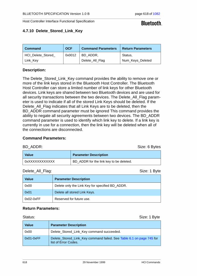
BLUETOOTH SPECIFICATION Version 1.0 B page 618 of 1082
Host Controller Interface Functional Specification
4.7.10 Delete_Stored_Link_Key
Description:
The Delete_Stored_Link_Key command provides the ability to remove one or more of the link keys stored in the Bluetooth Host Controller. The Bluetooth Host Controller can store a limited number of link keys for other Bluetooth devices. Link keys are shared between two Bluetooth devices and are used for all security transactions between the two devices. The Delete_All_Flag param-eter is used to indicate if all of the stored Link Keys should be deleted. If the Delete_All_Flag indicates that all Link Keys are to be deleted, then the BD_ADDR command parameter must be ignored This command provides the ability to negate all security agreements between two devices. The BD_ADDR command parameter is used to identify which link key to delete. If a link key is currently in use for a connection, then the link key will be deleted when all of the connections are disconnected.
Command Parameters:
BD_ADDR: Size: 6 Bytes
Delete_All_Flag: Size: 1 Byte
Return Parameters:
Status: Size: 1 Byte
Command OCF Command Parameters Return Parameters
HCI_Delete_Stored_
Link_Key
0x0012 BD_ADDR,
Delete_All_Flag
Status,
Num_Keys_Deleted
Value Parameter Description
0xXXXXXXXXXXXX BD_ADDR for the link key to be deleted.
Value Parameter Description
0x00 Delete only the Link Key for specified BD_ADDR.
0x01 Delete all stored Link Keys.
0x02-0xFF Reserved for future use.
Value Parameter Description
0x00 Delete_Stored_Link_Key command succeeded.
0x01-0xFF Delete_Stored_Link_Key command failed. See Table 6.1 on page 745 for list of Error Codes.
618 29 November 1999 HCI Commands

BLUETOOTH SPECIFICATION Version 1.0 B page 619 of 1082
Host Controller Interface Functional Specification
Num_Keys_Deleted: Size: 2 Bytes
Event(s) generated (unless masked away):
When the Delete_Stored_Link_Key command has completed, a Command Complete event will be generated.
Value Parameter Description
0xXXXX Number of Link Keys Deleted
HCI Commands 29 November 1999 619

BLUETOOTH SPECIFICATION Version 1.0 B page 620 of 1082
Host Controller Interface Functional Specification
4.7.11 Change_Local_Name
Description:
The Change_Local_Name command provides the ability to modify the user-friendly name for the Bluetooth device. A Bluetooth device may send a request to get the user-friendly name of another Bluetooth device. The user-friendly name provides the user with the ability to distinguish one Bluetooth device from another. The Name command parameter is a UTF-8 encoded string with up to 248 bytes in length. The Name command parameter should be null-terminated (0x00) if the UTF-8 encoded string is less than 248 bytes. Note: the Name Parameter is transmitted starting with the first byte of the name. This is an exception to the Little Endian order format for transmitting multi-byte parameters.
Command Parameters:
Name: Size: 248 Bytes
Return Parameters:
Status: Size: 1 Byte
Event(s) generated (unless masked away):
When the Change_Local_Name command has completed, a Command Com-plete event will be generated.
Command OCF Command Parameters Return Parameters
HCI_Change_Local_Name 0x0013 Name Status
Value Parameter Description
A UTF-8 encoded User-Friendly Descriptive Name for the device.
The UTF-8 encoded Name can be up to 248 bytes in length. If it is shorter than 248 bytes, the end is indicated by a NULL byte (0x00).
Null terminated Zero length String. Default.
Value Parameter Description
0x00 Change_Local_Name command succeeded.
0x01-0xFF Change_Local_Name command failed. See Table 6.1 on page 745 for list of Error Codes.
620 29 November 1999 HCI Commands

BLUETOOTH SPECIFICATION Version 1.0 B page 621 of 1082
Host Controller Interface Functional Specification
4.7.12 Read_Local_Name
Description:
The Read_Local_Name command provides the ability to read the stored user-friendly name for the Bluetooth device. The user-friendly name provides the user the ability to distinguish one Bluetooth device from another. The Name return parameter is a UTF-8 encoded string with up to 248 bytes in length. The Name return parameter will be null terminated (0x00) if the UTF-8 encoded string is less than 248 bytes. Note: the Name Parameter is transmitted starting with the first byte of the name. This is an exception to the Little Endian order format for transmitting multi-byte parameters.
Command Parameters:
None.
Return Parameters:
Status: Size: 1 Byte
Name: Size: 248 Bytes
Event(s) generated (unless masked away):
When the Read_Local_Name command has completed a Command Complete event will be generated.
Command OCF Command Parameters Return Parameters
HCI_Read_Local_Name 0x0014 Status, Name
Value Parameter Description
0x00 Read_Local_Name command succeeded
0x01-0xFF Read_Local_Name command failed see Table 6.1 on page 746 for list of Error Codes
Value Parameter Description
A UTF-8 encoded User Friendly Descriptive Name for the device.
The UTF-8 encoded Name can be up to 248 bytes in length. If it is shorter than 248 bytes, the end is indicated by a NULL byte (0x00).
HCI Commands 29 November 1999 621

BLUETOOTH SPECIFICATION Version 1.0 B page 622 of 1082
Host Controller Interface Functional Specification
4.7.13 Read_Connection_Accept_Timeout
Description:
This command will read the value for the Connection_Accept_Timeout configu-ration parameter. The Connection_Accept_Timeout configuration parameter allows the Bluetooth hardware to automatically deny a connection request after a specified time period has occurred and the new connection is not accepted. The parameter defines the time duration from when the Host Controller sends a Connection Request event until the Host Controller will automatically reject an incoming connection.
Command Parameters:
None.
Return Parameters:
Status: Size: 1 Byte
Conn_Accept_Timeout: Size: 2 Bytes
Event(s) generated (unless masked away):
When the Read_Connection_Timeout command has completed, a Command Complete event will be generated.
Command OCF Command Parameters Return Parameters
HCI_Read_Connection_Accept_Timeout
0x0015 Status,
Conn_Accept_Timeout
Value Parameter Description
0x00 Read_Connection_Accept_Timeout command succeeded.
0x01-0xFF Read_Connection_Accept_Timeout command failed. See Table 6.1 on page 745 for list of Error Codes.
Value Parameter Description
N = 0xXXXX Connection Accept Timeout measured in Number of Baseband slots.
Interval Length = N * 0.625 msec (1 Baseband slot)
Range for N: 0x0001 – 0xB540
Time Range: 0.625 msec -29 seconds
622 29 November 1999 HCI Commands

BLUETOOTH SPECIFICATION Version 1.0 B page 623 of 1082
Host Controller Interface Functional Specification
4.7.14 Write_Connection_Accept_Timeout
Description:
This command will write the value for the Connection_Accept_Timeout configu-ration parameter. The Connection_Accept_Timeout configuration parameter allows the Bluetooth hardware to automatically deny a connection request after a specified time interval has occurred and the new connection is not accepted. The parameter defines the time duration from when the Host Controller sends a Connection Request event until the Host Controller will automatically reject an incoming connection.
Command Parameters:
Conn_Accept_Timeout: Size: 2 Bytes
Return Parameters:
Status: Size: 1 Byte
Event(s) generated (unless masked away):
When the Write_Connection_Accept_Timeout command has completed, a Command Complete event will be generated.
Command OCF Command Parameters Return Parameters
HCI_Write_Connection_Accept_Timeout
0x0016 Conn_Accept_Timeout Status
Value Parameter Description
N = 0xXXXX Connection Accept Timeout measured in Number of Baseband slots.
Interval Length = N * 0.625 msec (1 Baseband slot)
Range for N: 0x0001 – 0xB540
Time Range: 0.625 msec - 29 seconds
Default: N = 0x1FA0 Time = 5 Sec
Value Parameter Description
0x00 Write_Connection_Accept_Timeout command succeeded.
0x01-0xFF Write_Connection_Accept_Timeout command failed. See Table 6.1 on page 745 for list of Error Codes.
HCI Commands 29 November 1999 623

BLUETOOTH SPECIFICATION Version 1.0 B page 624 of 1082
Host Controller Interface Functional Specification
4.7.15 Read_Page_Timeout
Description:
This command will read the value for the Page_Timeout configuration parame-ter. The Page_Timeout configuration parameter defines the maximum time the local Link Manager will wait for a baseband page response from the remote device at a locally initiated connection attempt. If this time expires and the remote device has not responded to the page at baseband level, the connec-tion attempt will be considered to have failed.
Command Parameters:
None.
Return Parameters:
Status: Size: 1 Byte
Page_Timeout: Size: 2 Bytes
Event(s) generated (unless masked away):
When the Read_Page_Timeout command has completed, a Command Com-plete event will be generated.
Command OCF Command Parameters Return Parameters
HCI_Read_Page_Timeout 0x0017 Status,
Page_Timeout
Value Parameter Description
0x00 Read_Page_Timeout command succeeded.
0x01-0xFF Read_Page_Timeout command failed. See Table 6.1 on page 745 for list of Error Codes.
Value Parameter Description
N = 0xXXXX Page Timeout measured in Number of Baseband slots.
Interval Length = N * 0.625 msec (1 Baseband slot)
Range for N: 0x0001 – 0xFFFF
Time Range: 0.625 msec -40.9 Seconds
624 29 November 1999 HCI Commands

BLUETOOTH SPECIFICATION Version 1.0 B page 625 of 1082
Host Controller Interface Functional Specification
4.7.16 Write_Page_Timeout
Description:
This command will write the value for the Page_Timeout configuration parame-ter. The Page_Timeout configuration parameter defines the maximum time the local Link Manager will wait for a baseband page response from the remote device at a locally initiated connection attempt. If this time expires and the remote device has not responded to the page at baseband level, the connec-tion attempt will be considered to have failed.
Command Parameters:
Page_Timeout: Size: 2 Bytes
Return Parameters:
Status: Size: 1 Byte
Event(s) generated (unless masked away):
When the Write_Page_Timeout command has completed, a Command Com-plete event will be generated.
Command OCF Command Parameters Return Parameters
HCI_Write_Page_Timeout 0x0018 Page_Timeout Status
Value Parameter Description
0 Illegal Page Timeout. Must be larger than 0.
N = 0xXXXX Page Timeout measured in Number of Baseband slots.
Interval Length = N * 0.625 msec (1 Baseband slot)
Range for N: 0x0001 – 0xFFFF
Time Range: 0.625 msec -40.9 Seconds
Default: N = 0x2000 Time = 5.12 Sec
Value Parameter Description
0x00 Write_Page_Timeout command succeeded.
0x01-0xFF Write_Page_Timeout command failed. See Table 6.1 on page 745 for list of Error Codes.
HCI Commands 29 November 1999 625

BLUETOOTH SPECIFICATION Version 1.0 B page 626 of 1082
Host Controller Interface Functional Specification
4.7.17 Read_Scan_Enable
Description:
This command will read the value for the Scan_Enable parameter. The Scan_Enable parameter controls whether or not the Bluetooth device will peri-odically scan for page attempts and/or inquiry requests from other Bluetooth devices. If Page_Scan is enabled, then the device will enter page scan mode based on the value of the Page_Scan_Interval and Page_Scan_Window parameters. If Inquiry_Scan is enabled, then the device will enter Inquiry Scan mode based on the value of the Inquiry_Scan_Interval and Inquiry_Scan_Window parameters.
Command Parameters:
None.
Return Parameters:
Status: Size: 1 Byte
Scan_Enable: Size: 1 Byte
Event(s) generated (unless masked away):
When the Read_Scan_Enable command has completed, a Command Com-plete event will be generated.
Command OCF Command Parameters Return Parameters
HCI_Read_Scan_Enable 0x0019 Status, Scan_Enable
Value Parameter Description
0x00 Read_Scan_Enable command succeeded.
0x01-0xFF Read_Scan_Enable command failed. See Table 6.1 on page 745 for list of Error Codes.
Value Parameter Description
0x00 No Scans enabled.
0x01 Inquiry Scan enabled.Page Scan disabled.
0x02 Inquiry Scan disabled.Page Scan enabled.
0x03 Inquiry Scan enabled.Page Scan enabled.
626 29 November 1999 HCI Commands

BLUETOOTH SPECIFICATION Version 1.0 B page 627 of 1082
Host Controller Interface Functional Specification
4.7.18 Write_Scan_Enable
Description:
This command will write the value for the Scan_Enable parameter. The Scan_Enable parameter controls whether or not the Bluetooth device will peri-odically scan for page attempts and/or inquiry requests from other Bluetooth devices. If Page_Scan is enabled, then the device will enter page scan mode based on the value of the Page_Scan_Interval and Page_Scan_Window parameters. If Inquiry_Scan is enabled, then the device will enter Inquiry Scan mode based on the value of the Inquiry_Scan_Interval and Inquiry_Scan_Window parameters.
Command Parameters:
Scan_Enable: Size: 1 Byte
Return Parameters:
Status: Size: 1 Byte
Event(s) generated (unless masked away):
When the Write_Scan_Enable command has completed, a Command Com-plete event will be generated.
Command OCF Command Parameters Return Parameters
HCI_Write_Scan_Enable 0x001A Scan_Enable Status
Value Parameter Description
0x00 No Scans enabled. Default.
0x01 Inquiry Scan enabled.Page Scan disabled.
0x02 Inquiry Scan disabled.Page Scan enabled.
0x03 Inquiry Scan enabled.Page Scan enabled.
Value Parameter Description
0x00 Write_Scan_Enable command succeeded.
0x01-0xFF Write_Scan_Enable command failed. See Table 6.1 on page 745 for list of Error Codes.
HCI Commands 29 November 1999 627

BLUETOOTH SPECIFICATION Version 1.0 B page 628 of 1082
Host Controller Interface Functional Specification
4.7.19 Read_Page_Scan_Activity
Description:
This command will read the value for Page_Scan_Activity configuration param-eters. The Page_Scan_Interval configuration parameter defines the amount of time between consecutive page scans. This time interval is defined from when the Host Controller started its last page scan until it begins the next page scan. The Page_Scan_Window configuration parameter defines the amount of time for the duration of the page scan. The Page_Scan_Window can only be less than or equal to the Page_Scan_Interval. Note: Page Scan is only performed when Page_Scan is enabled (see 4.7.17 and 4.7.18).
A changed Page_Scan_Interval could change the local Page_Scan_Repetition_Mode (see “Baseband Specification” on page 33, Keyword: SR-Mode).
Command Parameters:
None.
Return Parameters:
Status: Size: 1 Byte
Page_Scan_Interval: Size: 2 Bytes
Command OCF Command Parameters Return Parameters
HCI_Read_Page_Scan_Activity
0x001B Status,
Page_Scan_Interval,
Page_Scan_Window
Value Parameter Description
0x00 Read_Page_Scan_Activity command succeeded.
0x01-0xFF Read_Page_Scan_Activity command failed. See Table 6.1 on page 745 for list of Error Codes.
Value Parameter Description
N = 0xXXXX Size: 2 Bytes
Range: 0x0012 – 0x1000
Time = N * 0.625 msec
Range: 11.25 msec – 2560 msec
628 29 November 1999 HCI Commands

BLUETOOTH SPECIFICATION Version 1.0 B page 629 of 1082
Host Controller Interface Functional Specification
Page_Scan_Window: Size: 2 Bytes
Event(s) generated (unless masked away):
When the Read_Page_Scan_Activity command has completed, a Command Complete event will be generated.
Value Parameter Description
N = 0xXXXX Size: 2 Bytes
Range: 0x0012 – 0x1000
Time = N * 0.625 msec
Range: 11.25 msec – 2560 msec
HCI Commands 29 November 1999 629

BLUETOOTH SPECIFICATION Version 1.0 B page 630 of 1082
Host Controller Interface Functional Specification
4.7.20 Write_Page_Scan_Activity
Description:
This command will write the value for Page_Scan_Activity configuration parameter. The Page_Scan_Interval configuration parameter defines the amount of time between consecutive page scans. This is defined as the time interval from when the Host Controller started its last page scan until it begins the next page scan. The Page_Scan_Window configuration parameter defines the amount of time for the duration of the page scan. The Page_Scan_Window can only be less than or equal to the Page_Scan_Interval. Note: Page Scan is only performed when Page_Scan is enabled (see 4.7.17 and 4.7.18). A changed Page_Scan_Interval could change the local Page_Scan_Repetition_Mode (see “Baseband Specification” on page 33, Keyword: SR-Mode).
Command Parameters:
Page_Scan_Interval: Size: 2 Bytes
Page_Scan_Window: Size: 2 Bytes
Command OCF Command Parameters Return Parameters
HCI_Write_Page_Scan_Activity
0x001C Page_Scan_Interval,
Page_Scan_Window
Status
Value Parameter Description
N = 0xXXXX Size: 2 Bytes
Range: 0x0012 – 0x1000
Time = N * 0.625 msec
Range: 11.25 msec –2560 msec
Default: N = 0x0800
Time = 1.28 Sec
Value Parameter Description
N = 0xXXXX Size: 2 Bytes
Range: 0x0012 – 0x1000
Time = N * 0.625 msec
Range: 11.25 msec – 2560 msec
Default: N = 0x0012
Time = 11.25 msec
630 29 November 1999 HCI Commands

BLUETOOTH SPECIFICATION Version 1.0 B page 631 of 1082
Host Controller Interface Functional Specification
Return Parameters:
Status: Size: 1 Byte
Event(s) generated (unless masked away):
When the Write_Page_Scan_Activity command has completed, a Command Complete event will be generated.
Value Parameter Description
0x00 Write_Page_Scan_Activity command succeeded.
0x01-0xFF Write_Page_Scan_Activity command failed. See Table 6.1 on page 745 for list of Error Codes.
HCI Commands 29 November 1999 631
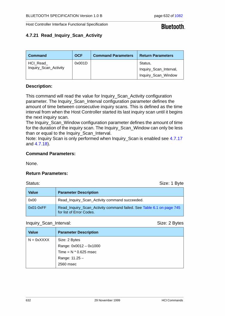
BLUETOOTH SPECIFICATION Version 1.0 B page 632 of 1082
Host Controller Interface Functional Specification
4.7.21 Read_Inquiry_Scan_Activity
Description:
This command will read the value for Inquiry_Scan_Activity configuration parameter. The Inquiry_Scan_Interval configuration parameter defines the amount of time between consecutive inquiry scans. This is defined as the time interval from when the Host Controller started its last inquiry scan until it begins the next inquiry scan. The Inquiry_Scan_Window configuration parameter defines the amount of time for the duration of the inquiry scan. The Inquiry_Scan_Window can only be less than or equal to the Inquiry_Scan_Interval.Note: Inquiry Scan is only performed when Inquiry_Scan is enabled see 4.7.17 and 4.7.18).
Command Parameters:
None.
Return Parameters:
Status: Size: 1 Byte
Inquiry_Scan_Interval: Size: 2 Bytes
Command OCF Command Parameters Return Parameters
HCI_Read_Inquiry_Scan_Activity
0x001D Status,
Inquiry_Scan_Interval,
Inquiry_Scan_Window
Value Parameter Description
0x00 Read_Inquiry_Scan_Activity command succeeded.
0x01-0xFF Read_Inquiry_Scan_Activity command failed. See Table 6.1 on page 745 for list of Error Codes.
Value Parameter Description
N = 0xXXXX Size: 2 Bytes
Range: 0x0012 – 0x1000
Time = N * 0.625 msec
Range: 11.25 –
2560 msec
632 29 November 1999 HCI Commands

BLUETOOTH SPECIFICATION Version 1.0 B page 633 of 1082
Host Controller Interface Functional Specification
Inquiry_Scan_Window: Size: 2 Bytes
Event(s) generated (unless masked away):
When the Read_Inquiry_Scan_Activity command has completed, a Command Complete event will be generated.
Value Parameter Description
N = 0xXXXX Size: 2 Bytes
Range: 0x0012 – 0x1000
Time = N * 0.625 msec
Range: 0.625 msec – 2560 msec
HCI Commands 29 November 1999 633

BLUETOOTH SPECIFICATION Version 1.0 B page 634 of 1082
Host Controller Interface Functional Specification
4.7.22 Write_Inquiry_Scan_Activity
Description:
This command will write the value for Inquiry_Scan_Activity configuration parameter. The Inquiry_Scan_Interval configuration parameter defines the amount of time between consecutive inquiry scans. This is defined as the time interval from when the Host Controller started its last inquiry scan until it begins the next inquiry scan. The Inquiry_Scan_Window configuration parameter defines the amount of time for the duration of the inquiry scan. The Inquiry_Scan_Window can only be less than or equal to the Inquiry_Scan_Interval.Note: Inquiry Scan is only performed when Inquiry_Scan is enabled (see 4.7.17 and 4.7.18).
Command Parameters:
Inquiry_Scan_Interval: Size: 2 Bytes
Inquiry_Scan_Window: Size: 2 Bytes
Command OCF Command Parameters Return Parameters
HCI_Write_Inquiry_Scan_Activity
0x001E Inquiry_Scan_Interval,
Inquiry_Scan_Window
Status
Value Parameter Description
N = 0xXXXX Size: 2 Bytes
Range: 0x0012 – 0x1000
Time = N * 0.625 msec
Range: 11.25 – 2560 msec
Default: N = 0x0800
Time = 1.28 Sec
Value Parameter Description
N = 0xXXXX Size: 2 Bytes
Range: 0x0012 – 0x1000
Time = N * 0.625 msec
Range: 11.25 msec – 2560 msec
Default: N = 0x0012
Time = 11.25 msec
634 29 November 1999 HCI Commands
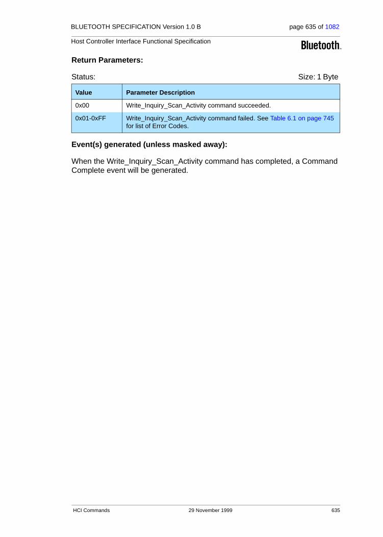
BLUETOOTH SPECIFICATION Version 1.0 B page 635 of 1082
Host Controller Interface Functional Specification
Return Parameters:
Status: Size: 1 Byte
Event(s) generated (unless masked away):
When the Write_Inquiry_Scan_Activity command has completed, a Command Complete event will be generated.
Value Parameter Description
0x00 Write_Inquiry_Scan_Activity command succeeded.
0x01-0xFF Write_Inquiry_Scan_Activity command failed. See Table 6.1 on page 745 for list of Error Codes.
HCI Commands 29 November 1999 635

BLUETOOTH SPECIFICATION Version 1.0 B page 636 of 1082
Host Controller Interface Functional Specification
4.7.23 Read_Authentication_Enable
Description:
This command will read the value for the Authentication_Enable parameter. The Authentication_Enable parameter controls if the local device requires to authenticate the remote device at connection setup (between the Create_Connection command or acceptance of an incoming ACL connection and the corresponding Connection Complete event). At connection setup, only the device(s) with the Authentication_Enable parameter enabled will try to authenticate the other device.
Note: Changing this parameter does not affect existing connections.
Command Parameters:
None.
Return Parameters:
Status: Size: 1 Byte
Authentication_Enable: Size: 1 Byte
Event(s) generated (unless masked away):
When the Read_Authentication_Enable command has completed, a Com-mand Complete event will be generated.
Command OCF Command Parameters Return Parameters
HCI_Read_
Authentication_Enable
0x001F Status,
Authentication_Enable
Value Parameter Description
0x00 Read_Authentication_Enable command succeeded.
0x01-0xFF Read_Authentication_Enable command failed.See Table 6.1 on page 745 for list of Error Codes.
Value Parameter Description
0x00 Authentication disabled.
0x01 Authentication enabled for all connections.
0x02-0xFF Reserved
636 29 November 1999 HCI Commands
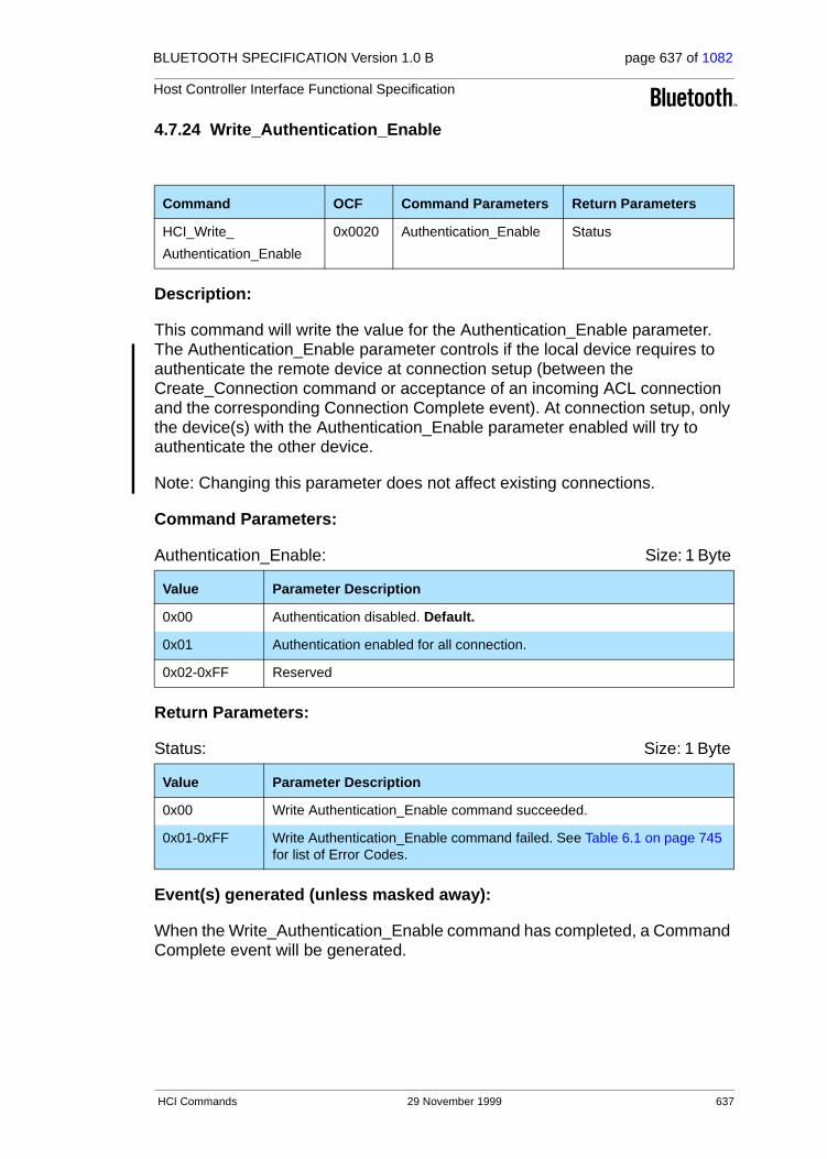
BLUETOOTH SPECIFICATION Version 1.0 B page 637 of 1082
Host Controller Interface Functional Specification
4.7.24 Write_Authentication_Enable
Description:
This command will write the value for the Authentication_Enable parameter. The Authentication_Enable parameter controls if the local device requires to authenticate the remote device at connection setup (between the Create_Connection command or acceptance of an incoming ACL connection and the corresponding Connection Complete event). At connection setup, only the device(s) with the Authentication_Enable parameter enabled will try to authenticate the other device.
Note: Changing this parameter does not affect existing connections.
Command Parameters:
Authentication_Enable: Size: 1 Byte
Return Parameters:
Status: Size: 1 Byte
Event(s) generated (unless masked away):
When the Write_Authentication_Enable command has completed, a Command Complete event will be generated.
Command OCF Command Parameters Return Parameters
HCI_Write_
Authentication_Enable
0x0020 Authentication_Enable Status
Value Parameter Description
0x00 Authentication disabled. Default.
0x01 Authentication enabled for all connection.
0x02-0xFF Reserved
Value Parameter Description
0x00 Write Authentication_Enable command succeeded.
0x01-0xFF Write Authentication_Enable command failed. See Table 6.1 on page 745 for list of Error Codes.
HCI Commands 29 November 1999 637

BLUETOOTH SPECIFICATION Version 1.0 B page 638 of 1082
Host Controller Interface Functional Specification
4.7.25 Read_Encryption_Mode
Description:
This command will read the value for the Encryption_Mode parameter. The Encryption_Mode parameter controls if the local device requires encryption to the remote device at connection setup (between the Create_Connection com-mand or acceptance of an incoming ACL connection and the corresponding Connection Complete event). At connection setup, only the device(s) with the Authentication_Enable parameter enabled and Encryption_Mode parameter enabled will try to encrypt the connection to the other device. Note: Changing this parameter does not affect existing connections.
Command Parameters:
None.
Return Parameters:
Status: Size: 1 Byte
Encryption_Mode: Size: 1 Byte
Event(s) generated (unless masked away):
When the Read_Encryption_Mode command has completed, a Command Complete event will be generated.
Command OCF Command Parameters Return Parameters
HCI_Read_Encryption_Mode 0x0021 Status,
Encryption_Mode
Value Parameter Description
0x00 Read_Encryption_Mode command succeeded.
0x01-0xFF Read_Encryption_Mode command failed. See Table 6.1 on page 745 for list of Error Codes.
Value Parameter Description
0x00 Encryption disabled.
0x01 Encryption only for point-to-point packets.
0x02 Encryption for both point-to-point and broadcast packets.
0x03-0xFF Reserved.
638 29 November 1999 HCI Commands
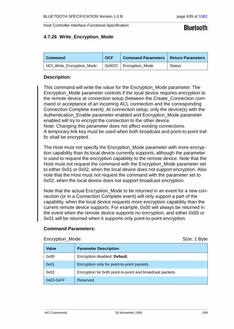
BLUETOOTH SPECIFICATION Version 1.0 B page 639 of 1082
Host Controller Interface Functional Specification
4.7.26 Write_Encryption_Mode
Description:
This command will write the value for the Encryption_Mode parameter. The Encryption_Mode parameter controls if the local device requires encryption to the remote device at connection setup (between the Create_Connection com-mand or acceptance of an incoming ACL connection and the corresponding Connection Complete event). At connection setup, only the device(s) with the Authentication_Enable parameter enabled and Encryption_Mode parameter enabled will try to encrypt the connection to the other device. Note: Changing this parameter does not affect existing connections. A temporary link key must be used when both broadcast and point-to-point traf-fic shall be encrypted.
The Host must not specify the Encryption_Mode parameter with more encryp-tion capability than its local device currently supports, although the parameter is used to request the encryption capability to the remote device. Note that the Host must not request the command with the Encryption_Mode parameter set to either 0x01 or 0x02, when the local device does not support encryption. Also note that the Host must not request the command with the parameter set to 0x02, when the local device does not support broadcast encryption.
Note that the actual Encryption_Mode to be returned in an event for a new con-nection (or in a Connection Complete event) will only support a part of the capability, when the local device requests more encryption capability than the current remote device supports. For example, 0x00 will always be returned in the event when the remote device supports no encryption, and either 0x00 or 0x01 will be returned when it supports only point-to-point encryption.
Command Parameters:
Encryption_Mode: Size: 1 Byte
Command OCF Command Parameters Return Parameters
HCI_Write_Encryption_Mode 0x0022 Encryption_Mode Status
Value Parameter Description
0x00 Encryption disabled. Default.
0x01 Encryption only for point-to-point packets.
0x02 Encryption for both point-to-point and broadcast packets.
0x03-0xFF Reserved.
HCI Commands 29 November 1999 639

BLUETOOTH SPECIFICATION Version 1.0 B page 640 of 1082
Host Controller Interface Functional Specification
Return Parameters:
Status: Size: 1 Byte
Event(s) generated (unless masked away):
When the Write_Encryption_Mode command has completed, a Command Complete event will be generated.
Value Parameter Description
0x00 Write_Encryption_Mode command succeeded.
0x01-0xFF Write_Encryption_Mode command failed. See Table 6.1 on page 745 for list of Error Codes.
640 29 November 1999 HCI Commands

BLUETOOTH SPECIFICATION Version 1.0 B page 641 of 1082
Host Controller Interface Functional Specification
4.7.27 Read_Class_of_Device
Description:
This command will read the value for the Class_of_Device parameter. The Class_of_Device parameter is used to indicate the capabilities of the local device to other devices.
Command Parameters:
None.
Return Parameters:
Status: Size: 1 Byte
Class_of_Device: Size: 3 Bytes
Event(s) generated (unless masked away):
When the Read_Class_of_Device command has completed, a Command Complete event will be generated.
Command OCF Command Parameters Return Parameters
HCI_Read_Class_of_Device 0x0023 Status,
Class_of_Device
Value Parameter Description
0x00 Read_Class_of_Device command succeeded.
0x01-0xFF Read_Class_of_Device command failed. See Table 6.1 on page 745 for list of Error Codes.
Value Parameter Description
0xXXXXXX Class of Device for the device.
HCI Commands 29 November 1999 641

BLUETOOTH SPECIFICATION Version 1.0 B page 642 of 1082
Host Controller Interface Functional Specification
4.7.28 Write_Class_of_Device
Description:
This command will write the value for the Class_of_Device parameter. The Class_of_Device parameter is used to indicate the capabilities of the local device to other devices.
Command Parameters:
Class_of_Device: Size: 3 Bytes
Return Parameters:
Status: Size: 1 Byte
Event(s) generated (unless masked away):
When the Write_Class_of_Device command has completed, a Command Complete event will be generated.
Command OCF Command ParametersReturn Parameters
HCI_Write_Class_of_Device 0x0024 Class_of_Device Status
Value Parameter Description
0xXXXXXX Class of Device for the device.
Value Parameter Description
0x00 Write_Class_of_Device command succeeded.
0x01-0xFF Write_Class_of_Device command failed. See Table 6.1 on page 745 for list of Error Codes.
642 29 November 1999 HCI Commands

BLUETOOTH SPECIFICATION Version 1.0 B page 643 of 1082
Host Controller Interface Functional Specification
4.7.29 Read_Voice_Setting
Description:
This command will read the values for the Voice_Setting parameter. The Voice_Setting parameter controls all the various settings for voice connections. These settings apply to all voice connections, and cannot be set for individual voice connections. The Voice_Setting parameter controls the configuration for voice connections: Input Coding, Air coding format, input data format, Input sample size, and linear PCM parameter.
Command Parameters:
None.
Return Parameters:
Status: Size: 1 Byte
Voice_Setting: Size: 2 Bytes (10 Bits meaningful)
Command OCF Command Parameters Return Parameters
HCI_Read_Voice_Setting 0x0025 Status,
Voice_Setting
Value Parameter Description
0x00 Read_Voice_Setting command succeeded.
0x01-0xFF Read_Voice_Setting command failed. See Table 6.1 on page 745 for list of Error Codes.
Value Parameter Description
00XXXXXXXX Input Coding: Linear
01XXXXXXXX Input Coding: µ-law Input Coding
10XXXXXXXX Input Coding: A-law Input Coding
11XXXXXXXX Reserved for Future Use
XX00XXXXXX Input Data Format: 1’s complement
XX01XXXXXX Input Data Format: 2’s complement
XX10XXXXXX Input Data Format: Sign-Magnitude
XX11XXXXXX Reserved for Future Use
XXXX0XXXXX Input Sample Size: 8-bit (only for Liner PCM)
XXXX1XXXXX Input Sample Size: 16-bit (only for Liner PCM)
HCI Commands 29 November 1999 643

BLUETOOTH SPECIFICATION Version 1.0 B page 644 of 1082
Host Controller Interface Functional Specification
Event(s) generated (unless masked away):
When the Read_Voice_Setting command has completed, a Command Com-plete event will be generated.
Value Parameter Description
XXXXXnnnXX Linear_PCM_Bit_Pos: # bit positions that MSB of sample is away from starting at MSB (only for Liner PCM).
XXXXXXXX00 Air Coding Format: CVSD
XXXXXXXX01 Air Coding Format: µ-law
XXXXXXXX10 Air Coding Format: A-law
XXXXXXXX11 Reserved
644 29 November 1999 HCI Commands

BLUETOOTH SPECIFICATION Version 1.0 B page 645 of 1082
Host Controller Interface Functional Specification
4.7.30 Write_Voice_Setting
Description:
This command will write the values for the Voice_Setting parameter. The Voice_Setting parameter controls all the various settings for the voice connec-tions. These settings apply to all voice connections and cannot be set for indi-vidual voice connections. The Voice_Setting parameter controls the configuration for voice connections: Input Coding, Air coding format, input data format, Input sample size, and linear PCM parameter.
Command Parameters:
Voice_Setting: Size: 2 Bytes (10 Bits meaningful)
Command OCF Command Parameters Return Parameters
HCI_Write_Voice_Setting 0x0026 Voice_Setting Status
Value Parameter Description
00XXXXXXXX Input Coding: Linear
01XXXXXXXX Input Coding: µ-law Input Coding
10XXXXXXXX Input Coding: A-law Input Coding
11XXXXXXXX Reserved for Future Use
XX00XXXXXX Input Data Format: 1’s complement
XX01XXXXXX Input Data Format: 2’s complement
XX10XXXXXX Input Data Format: Sign-Magnitude
XX11XXXXXX Reserved for Future Use
XXXX0XXXXX Input Sample Size: 8 bit (only for Liner PCM)
XXXX1XXXXX Input Sample Size: 16 bit (only for Liner PCM)
XXXXXnnnXX Linear_PCM_Bit_Pos: # bit positions that MSB of sample is away from starting at MSB (only for Liner PCM)
XXXXXXXX00 Air Coding Format: CVSD
XXXXXXXX01 Air Coding Format: µ-law
XXXXXXXX10 Air Coding Format: A-law
XXXXXXXX11 Reserved
0001100000 Default Condition
HCI Commands 29 November 1999 645

BLUETOOTH SPECIFICATION Version 1.0 B page 646 of 1082
Host Controller Interface Functional Specification
Return Parameters:
Status: Size: 1 Byte
Event(s) generated (unless masked away):
When the Write_Voice_Setting command has completed, a Command Com-plete event will be generated.
Value Parameter Description
0x00 Write_Voice_Setting command succeeded.
0x01-0xFF Write_Voice_Setting command failed. See Table 6.1 on page 745 for list of Error Codes.
646 29 November 1999 HCI Commands

BLUETOOTH SPECIFICATION Version 1.0 B page 647 of 1082
Host Controller Interface Functional Specification
4.7.31 Read_Automatic_Flush_Timeout
Description:
This command will read the value for the Flush_Timeout parameter for the specified connection handle. The Flush_Timeout parameter is used for ACL connections ONLY. The Flush_Timeout parameter defines the amount of time before all chunks of the L2CAP packet, of which a baseband packet is currently being transmitted, are automatically flushed by the Host Controller. The timeout period starts when a transmission attempt is made for the first baseband packet of an L2CAP packet. This allows ACL packets to be automatically flushed without the Host device issuing a Flush command. The Read_Automatic_Flush_Timeout command provides support for isochronous data, such as video. When the L2CAP packet that is currently being transmit-ted is automatically ‘flushed’, the Failed Contact Counter is incremented by one. The first chunk of the next L2CAP packet to be transmitted for the speci-fied connection handle may already be stored in the Host Controller. In that case, the transmission of the first baseband packet containing data from that L2CAP packet can begin immediately. If the next L2CAP packet is not stored in the Host Controller, all data that is sent to the Host Controller after the flush for the same connection handle will be discarded by the Host Controller until an HCI Data Packet having the start Packet_Boundary_Flag (0x02) is received. When this happens, a new transmission attempt will be made.
Command Parameters:
Connection_Handle: Size: 2 Bytes (12 Bits meaningful)
Return Parameters:
Status: Size: 1 Byte
Command OCF Command Parameters Return Parameters
HCI_Read_Automatic_Flush_
Timeout
0x0027 Connection_Handle Status,
Connection_Handle,
Flush_Timeout
Value Parameter Description
0xXXXX Specifies which Connection Handle’s Flush Timeout to read.
Range: 0x0000-0x0EFF (0x0F00 - 0x0FFF Reserved for future use)
Value Parameter Description
0x00 Read_Automatic_Flush_Timeout command succeeded.
0x01-0xFF Read_Automatic_Flush_Timeout command failed. See Table 6.1 on page 745 for list of Error Codes.
HCI Commands 29 November 1999 647

BLUETOOTH SPECIFICATION Version 1.0 B page 648 of 1082
Host Controller Interface Functional Specification
Connection_Handle: Size: 2 Bytes (12 Bits meaningful)
Flush_Timeout: Size: 2 Bytes
Event(s) generated (unless masked away):
When the Read_Automatic_Flush_Timeout command has completed, a Command Complete event will be generated.
Value Parameter Description
0xXXXX Specifies which Connection Handle’s Flush Timeout has been read.
Range: 0x0000-0x0EFF (0x0F00 - 0x0FFF Reserved for future use)
Value Parameter Description
0 Timeout = ∞; No Automatic Flush
N = 0xXXXX Flush Timeout = N * 0.625 msec
Size: 11 bits
Range: 0x0001 – 0x07FF
648 29 November 1999 HCI Commands

BLUETOOTH SPECIFICATION Version 1.0 B page 649 of 1082
Host Controller Interface Functional Specification
4.7.32 Write_Automatic_Flush_Timeout
Description:
This command will write the value for the Flush_Timeout parameter for the specified connection handle. The Flush_Timeout parameter is used for ACL connections ONLY. The Flush_Timeout parameter defines the amount of time before all chunks of the L2CAP packet, of which a baseband packet is currently being transmitted, are automatically flushed by the Host Controller. The timeout period starts when a transmission attempt is made for the first baseband packet of an L2CAP packet. This allows ACL packets to be automatically flushed without the Host device issuing a Flush command. The Write_Automatic_Flush_Timeout command provides support for isochronous data, such as video. When the L2CAP packet that is currently being transmit-ted is automatically ‘flushed’, the Failed Contact Counter is incremented by one. The first chunk of the next L2CAP packet to be transmitted for the speci-fied connection handle may already be stored in the Host Controller. In that case, the transmission of the first baseband packet containing data from that L2CAP packet can begin immediately. If the next L2CAP packet is not stored in the Host Controller, all data that is sent to the Host Controller after the flush for the same connection handle will be discarded by the Host Controller until an HCI Data Packet having the start Packet_Boundary_Flag (0x02) is received. When this happens, a new transmission attempt will be made.
Command Parameters:
Connection_Handle: Size: 2 Bytes (12 Bits meaningful)
Flush_Timeout: Size: 2 Bytes
Command OCF Command Parameters Return Parameters
HCI_Write_Automatic_Flush_Timeout
0x0028 Connection_Handle,
Flush_Timeout
Status,
Connection_Handle
Value Parameter Description
0xXXXX Specifies which Connection Handle’s Flush Timeout to write to.
Range: 0x0000-0x0EFF (0x0F00 - 0x0FFF Reserved for future use)
Value Parameter Description
0 Timeout = ∞; No Automatic Flush. Default.
N = 0xXXXX Flush Timeout = N * 0.625 msec
Size: 11 bits
Range: 0x0001 – 0x07FF
HCI Commands 29 November 1999 649

BLUETOOTH SPECIFICATION Version 1.0 B page 650 of 1082
Host Controller Interface Functional Specification
Return Parameters:
Status: Size: 1 Byte
Connection_Handle: Size: 2 Bytes (12 Bits meaningful)
Event(s) generated (unless masked away):
When the Write_Automatic_Flush_Timeout command has completed, a Command Complete event will be generated.
Value Parameter Description
0x00 Write_Automatic_Flush_Timeout command succeeded.
0x01-0xFF Write_Automatic_Flush_Timeout command failed. See Table 6.1 on page 745 for list of Error Codes.
Value Parameter Description
0xXXXX Specifies which Connection Handle’s Flush Timeout has been written.
Range: 0x0000-0x0EFF (0x0F00 - 0x0FFF Reserved for future use)
650 29 November 1999 HCI Commands

BLUETOOTH SPECIFICATION Version 1.0 B page 651 of 1082
Host Controller Interface Functional Specification
4.7.33 Read_Num_Broadcast_Retransmissions
Description:
This command will read the device’s parameter value for the Number of Broad-cast Retransmissions. Broadcast packets are not acknowledged and are unre-liable. The Number of Broadcast Retransmissions parameter is used to increase the reliability of a broadcast message by retransmitting the broadcast message multiple times. This parameter defines the number of times the device will retransmit a broadcast data packet. This parameter should be adjusted as the link quality measurement changes.
Command Parameters:
None.
Return Parameters:
Status: Size: 1 Byte
Num_Broadcast_Retran: Size: 1 Byte
Event(s) generated (unless masked away):
When the Read_Num_Broadcast_Retransmission command has completed, a Command Complete event will be generated.
Command OCFCommand Parameters Return Parameters
HCI_Read_Num_Broadcast_
Retransmissions
0x0029 Status, Num_Broadcast_Retran
Value Parameter Description
0x00 Read_Num_Broadcast_Retransmissions command succeeded.
0x01-0xFF Read_Num_Broadcast_Retransmissions command failed. See Table 6.1 on page 745 for list of Error Codes.
Value Parameter Description
N = 0xXX Number of Broadcast Retransmissions = N
Range 0x00-0xFF
HCI Commands 29 November 1999 651
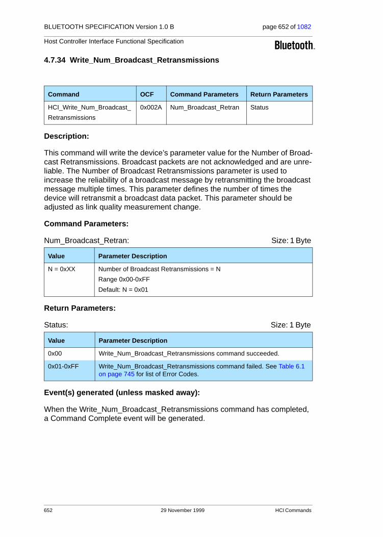
BLUETOOTH SPECIFICATION Version 1.0 B page 652 of 1082
Host Controller Interface Functional Specification
4.7.34 Write_Num_Broadcast_Retransmissions
Description:
This command will write the device’s parameter value for the Number of Broad-cast Retransmissions. Broadcast packets are not acknowledged and are unre-liable. The Number of Broadcast Retransmissions parameter is used to increase the reliability of a broadcast message by retransmitting the broadcast message multiple times. This parameter defines the number of times the device will retransmit a broadcast data packet. This parameter should be adjusted as link quality measurement change.
Command Parameters:
Num_Broadcast_Retran: Size: 1 Byte
Return Parameters:
Status: Size: 1 Byte
Event(s) generated (unless masked away):
When the Write_Num_Broadcast_Retransmissions command has completed, a Command Complete event will be generated.
Command OCF Command Parameters Return Parameters
HCI_Write_Num_Broadcast_
Retransmissions
0x002A Num_Broadcast_Retran Status
Value Parameter Description
N = 0xXX Number of Broadcast Retransmissions = N
Range 0x00-0xFF
Default: N = 0x01
Value Parameter Description
0x00 Write_Num_Broadcast_Retransmissions command succeeded.
0x01-0xFF Write_Num_Broadcast_Retransmissions command failed. See Table 6.1 on page 745 for list of Error Codes.
652 29 November 1999 HCI Commands

BLUETOOTH SPECIFICATION Version 1.0 B page 653 of 1082
Host Controller Interface Functional Specification
4.7.35 Read_Hold_Mode_Activity
Description:
This command will read the value for the Hold_Mode_Activity parameter. The Hold_Mode_Activity value is used to determine what activities should be sus-pended when the device is in hold mode. After the hold period has expired, the device will return to the previous mode of operation. Multiple hold mode activi-ties may be specified for the Hold_Mode_Activity parameter by performing a bitwise OR operation of the different activity types. If no activities are sus-pended, then all of the current Periodic Inquiry, Inquiry Scan, and Page Scan settings remain valid during the Hold Mode. If the Hold_Mode_Activity parame-ter is set to Suspend Page Scan, Suspend Inquiry Scan, and Suspend Periodic Inquiries, then the device can enter a low-power state during the Hold Mode period, and all activities are suspended. Suspending multiple activities can be specified for the Hold_Mode_Activity parameter by performing a bitwise OR operation of the different activity types.The Hold Mode Activity is only valid if all connections are in Hold Mode.
Command Parameters:
None.
Return Parameters:
Status: Size: 1 Byte
Hold_Mode_Activity: Size: 1 Byte
Command OCFCommand Parameters Return Parameters
HCI_Read_Hold_Mode_Activity 0x002B Status, Hold_Mode_Activity
Value Parameter Description
0x00 Read_Hold_Mode_Activity command succeeded.
0x01-0xFF Read_Hold_Mode_Activity command failed. See Table 6.1 on page 745 for list of Error Codes.
Value Parameter Description
0x00 Maintain current Power State.
0x01 Suspend Page Scan.
0x02 Suspend Inquiry Scan.
0x04 Suspend Periodic Inquiries.
0x08-0xFF Reserved for Future Use.
HCI Commands 29 November 1999 653
BLUETOOTH SPECIFICATION Version 1.0 B page 654 of 1082
Host Controller Interface Functional Specification
Event(s) generated (unless masked away):
When the Read_Hold_Mode_Activity command has completed, a Command Complete event will be generated.
654 29 November 1999 HCI Commands
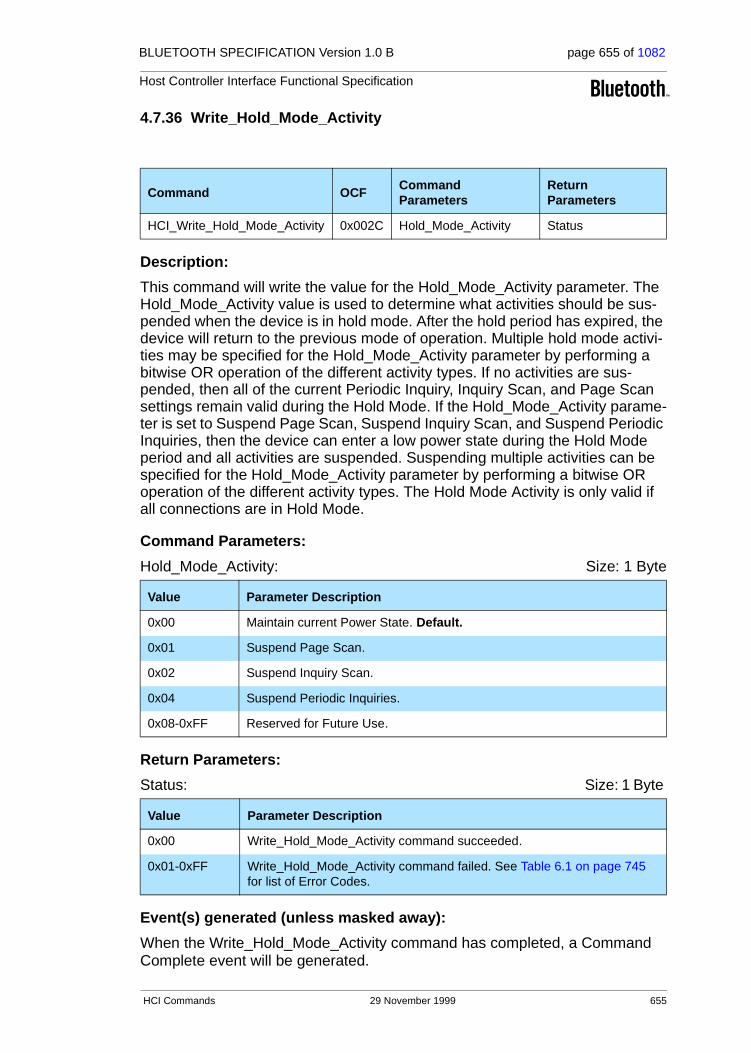
BLUETOOTH SPECIFICATION Version 1.0 B page 655 of 1082
Host Controller Interface Functional Specification
4.7.36 Write_Hold_Mode_Activity
Description:
This command will write the value for the Hold_Mode_Activity parameter. The Hold_Mode_Activity value is used to determine what activities should be sus-pended when the device is in hold mode. After the hold period has expired, the device will return to the previous mode of operation. Multiple hold mode activi-ties may be specified for the Hold_Mode_Activity parameter by performing a bitwise OR operation of the different activity types. If no activities are sus-pended, then all of the current Periodic Inquiry, Inquiry Scan, and Page Scan settings remain valid during the Hold Mode. If the Hold_Mode_Activity parame-ter is set to Suspend Page Scan, Suspend Inquiry Scan, and Suspend Periodic Inquiries, then the device can enter a low power state during the Hold Mode period and all activities are suspended. Suspending multiple activities can be specified for the Hold_Mode_Activity parameter by performing a bitwise OR operation of the different activity types. The Hold Mode Activity is only valid if all connections are in Hold Mode.
Command Parameters:
Hold_Mode_Activity: Size: 1 Byte
Return Parameters:
Status: Size: 1 Byte
Event(s) generated (unless masked away):
When the Write_Hold_Mode_Activity command has completed, a Command Complete event will be generated.
Command OCFCommand Parameters
Return Parameters
HCI_Write_Hold_Mode_Activity 0x002C Hold_Mode_Activity Status
Value Parameter Description
0x00 Maintain current Power State. Default.
0x01 Suspend Page Scan.
0x02 Suspend Inquiry Scan.
0x04 Suspend Periodic Inquiries.
0x08-0xFF Reserved for Future Use.
Value Parameter Description
0x00 Write_Hold_Mode_Activity command succeeded.
0x01-0xFF Write_Hold_Mode_Activity command failed. See Table 6.1 on page 745 for list of Error Codes.
HCI Commands 29 November 1999 655

BLUETOOTH SPECIFICATION Version 1.0 B page 656 of 1082
Host Controller Interface Functional Specification
4.7.37 Read_Transmit_Power_Level
Description:
This command will read the values for the Transmit_Power_Level parameter for the specified Connection Handle. The Connection_Handle must be a Connection_Handle for an ACL connection.
Command Parameters:
Connection_Handle: Size: 2 Bytes (12 Bits meaningful)
Type: Size: 1 Byte
Return Parameters:
Status: Size: 1 Byte
Connection_Handle: Size: 2 Bytes (12 Bits meaningful)
Command OCF Command Parameters Return Parameters
HCI_Read_Transmit_
Power_Level
0x002D Connection_Handle,
Type
Status,
Connection_Handle,
Transmit_Power_Level
Value Parameter Description
0xXXXX Specifies which Connection Handle’s Transmit Power Level setting to read.
Range: 0x0000-0x0EFF (0x0F00 - 0x0FFF Reserved for future use)
Value Parameter Description
0x00 Read Current Transmit Power Level.
0x01 Read Maximum Transmit Power Level.
0x02-0xFF Reserved
Value Parameter Description
0x00 Read_Transmit_Power_Level command succeeded.
0x01-0xFF Read_Transmit_Power_Level command failed. See Table 6.1 on page 745 for list of Error Codes.
Value Parameter Description
0xXXXX Specifies which Connection Handle’s Transmit Power Level setting is returned.
Range: 0x0000-0x0EFF (0x0F00 - 0x0FFF Reserved for future use)
656 29 November 1999 HCI Commands
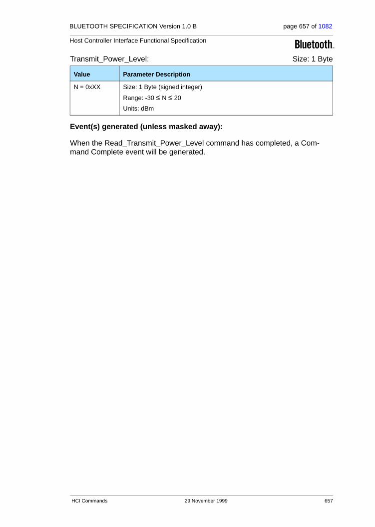
BLUETOOTH SPECIFICATION Version 1.0 B page 657 of 1082
Host Controller Interface Functional Specification
Transmit_Power_Level: Size: 1 Byte
Event(s) generated (unless masked away):
When the Read_Transmit_Power_Level command has completed, a Com-mand Complete event will be generated.
Value Parameter Description
N = 0xXX Size: 1 Byte (signed integer)
Range: -30 ≤ N ≤ 20
Units: dBm
HCI Commands 29 November 1999 657

BLUETOOTH SPECIFICATION Version 1.0 B page 658 of 1082
Host Controller Interface Functional Specification
4.7.38 Read_SCO_Flow_Control_Enable
Description:
The Read_SCO_Flow_Control_Enable command provides the ability to read the SCO_Flow_Control_Enable setting. By using this setting, the Host can decide if the Host Controller will send Number Of Completed Packets events for SCO Connection Handles. This setting allows the Host to enable and dis-able SCO flow control. Note: the SCO_Flow_Control_Enable setting can only be changed if no con-nections exist.
Command Parameters:
None.
Return Parameters:
Status: Size: 1 Byte
SCO_Flow_Control_Enable: Size: 1 Byte
Event(s) generated (unless masked away):
When the Read_SCO_Flow_Control_Enable command has completed a Com-mand Complete event will be generated.
Command OCF Command Parameters Return Parameters
HCI_Read_SCO_Flow_Control_Enable
0x002E Status, SCO_Flow_Control_Enable
Value Parameter Description
0x00 Read_SCO_Flow_Control_Enable command succeeded
0x01-0xFF Read_SCO_Flow_Control_Enable command failed see Table 6.1 on page 746 for list of Error Codes
Value Parameter Description
0x00 SCO Flow Control is disabled. No Number of Completed Packets events will be sent from the Host Controller for SCO Connection Handles.
0x01 SCO Flow Control is enabled. Number of Completed Packets events will be sent from the Host Controller for SCO Connection Handles.
658 29 November 1999 HCI Commands
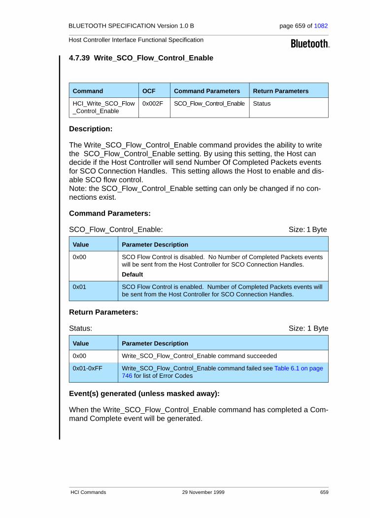
BLUETOOTH SPECIFICATION Version 1.0 B page 659 of 1082
Host Controller Interface Functional Specification
4.7.39 Write_SCO_Flow_Control_Enable
Description:
The Write_SCO_Flow_Control_Enable command provides the ability to write the SCO_Flow_Control_Enable setting. By using this setting, the Host can decide if the Host Controller will send Number Of Completed Packets events for SCO Connection Handles. This setting allows the Host to enable and dis-able SCO flow control. Note: the SCO_Flow_Control_Enable setting can only be changed if no con-nections exist.
Command Parameters:
SCO_Flow_Control_Enable: Size: 1 Byte
Return Parameters:
Status: Size: 1 Byte
Event(s) generated (unless masked away):
When the Write_SCO_Flow_Control_Enable command has completed a Com-mand Complete event will be generated.
Command OCF Command Parameters Return Parameters
HCI_Write_SCO_Flow_Control_Enable
0x002F SCO_Flow_Control_Enable Status
Value Parameter Description
0x00 SCO Flow Control is disabled. No Number of Completed Packets events will be sent from the Host Controller for SCO Connection Handles.
Default
0x01 SCO Flow Control is enabled. Number of Completed Packets events will be sent from the Host Controller for SCO Connection Handles.
Value Parameter Description
0x00 Write_SCO_Flow_Control_Enable command succeeded
0x01-0xFF Write_SCO_Flow_Control_Enable command failed see Table 6.1 on page 746 for list of Error Codes
HCI Commands 29 November 1999 659

BLUETOOTH SPECIFICATION Version 1.0 B page 660 of 1082
Host Controller Interface Functional Specification
4.7.40 Set_Host_Controller_To_Host_Flow_Control
Description:
This command is used by the Host to turn flow control on or off in the direction from the Host Controller to the Host. If flow control is turned off, the Host should not send the Host_Number_Of_Completed_Packets command. That command will be ignored by the Host Controller if it is sent by the Host and flow control is off.
Command Parameters:
Flow_Control_Enable: Size: 1 Byte
Return Parameters:
Status: Size: 1 Byte
Event(s) generated (unless masked away):
When the Set_Host_Controller_To_Host_Flow_Control command has completed, a Command Complete event will be generated.
Command OCF Command Parameters Return Parameters
HCI_Set_Host_Controller_To_Host_Flow_Control
0x0031 Flow_Control_Enable Status
Value Parameter Description
0x00 Flow control off in direction from Host Controller to Host. Default.
0x01 Flow control on in direction from Host Controller to Host.
0x02-0xFF Reserved
Value Parameter Description
0x00 Set_Host_Controller_To_Host_Flow_Control command succeeded.
0x01-0xFF Set_Host_Controller_To_Host_Flow_Control command failed. See Table 6.1 on page 7450 for list of Error Codes.
660 29 November 1999 HCI Commands
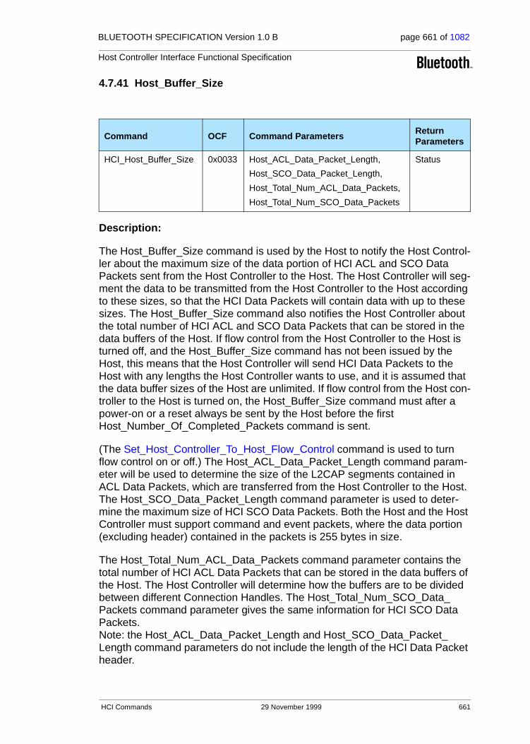
BLUETOOTH SPECIFICATION Version 1.0 B page 661 of 1082
Host Controller Interface Functional Specification
4.7.41 Host_Buffer_Size
Description:
The Host_Buffer_Size command is used by the Host to notify the Host Control-ler about the maximum size of the data portion of HCI ACL and SCO Data Packets sent from the Host Controller to the Host. The Host Controller will seg-ment the data to be transmitted from the Host Controller to the Host according to these sizes, so that the HCI Data Packets will contain data with up to these sizes. The Host_Buffer_Size command also notifies the Host Controller about the total number of HCI ACL and SCO Data Packets that can be stored in the data buffers of the Host. If flow control from the Host Controller to the Host is turned off, and the Host_Buffer_Size command has not been issued by the Host, this means that the Host Controller will send HCI Data Packets to the Host with any lengths the Host Controller wants to use, and it is assumed that the data buffer sizes of the Host are unlimited. If flow control from the Host con-troller to the Host is turned on, the Host_Buffer_Size command must after a power-on or a reset always be sent by the Host before the first Host_Number_Of_Completed_Packets command is sent.
(The Set_Host_Controller_To_Host_Flow_Control command is used to turn flow control on or off.) The Host_ACL_Data_Packet_Length command param-eter will be used to determine the size of the L2CAP segments contained in ACL Data Packets, which are transferred from the Host Controller to the Host. The Host_SCO_Data_Packet_Length command parameter is used to deter-mine the maximum size of HCI SCO Data Packets. Both the Host and the Host Controller must support command and event packets, where the data portion (excluding header) contained in the packets is 255 bytes in size.
The Host_Total_Num_ACL_Data_Packets command parameter contains the total number of HCI ACL Data Packets that can be stored in the data buffers of the Host. The Host Controller will determine how the buffers are to be divided between different Connection Handles. The Host_Total_Num_SCO_Data_Packets command parameter gives the same information for HCI SCO Data Packets. Note: the Host_ACL_Data_Packet_Length and Host_SCO_Data_Packet_Length command parameters do not include the length of the HCI Data Packet header.
Command OCF Command ParametersReturn Parameters
HCI_Host_Buffer_Size 0x0033 Host_ACL_Data_Packet_Length,
Host_SCO_Data_Packet_Length,
Host_Total_Num_ACL_Data_Packets,
Host_Total_Num_SCO_Data_Packets
Status
HCI Commands 29 November 1999 661

BLUETOOTH SPECIFICATION Version 1.0 B page 662 of 1082
Host Controller Interface Functional Specification
Command Parameters:
Host_ACL_Data_Packet_Length: Size: 2 Bytes
Host_SCO_Data_Packet_Length: Size: 1 Byte
Host_Total_Num_ACL_Data_Packets: Size: 2 Bytes
Host_Total_Num_SCO_Data_Packets: Size: 2 Bytes
Return Parameters:
Status: Size: 1 Byte
Event(s) generated (unless masked away):
When the Host_Buffer_Size command has completed, a Command Complete event will be generated.
Value Parameter Description
0xXXXX Maximum length (in bytes) of the data portion of each HCI ACL Data Packet that the Host is able to accept.
Value Parameter Description
0xXX Maximum length (in bytes) of the data portion of each HCI SCO Data Packet that the Host is able to accept.
Value Parameter Description
0xXXXX Total number of HCI ACL Data Packets that can be stored in the data buffers of the Host.
Value Parameter Description
0xXXXX Total number of HCI SCO Data Packets that can be stored in the data buffers of the Host.
Value Parameter Description
0x00 Host_Buffer_Size command succeeded.
0x01-0xFF Host_Buffer_Size command failed. See Table 6.1 on page 745 for list of Error Codes.
662 29 November 1999 HCI Commands

BLUETOOTH SPECIFICATION Version 1.0 B page 663 of 1082
Host Controller Interface Functional Specification
4.7.42 Host_Number_Of_Completed_Packets
Description:
The Host_Number_Of_Completed_Packets command is used by the Host to indicate to the Host Controller the number of HCI Data Packets that have been completed for each Connection Handle since the previous Host_Number_Of_Completed_Buffers command was sent to the Host Controller. This means that the corresponding buffer space has been freed in the Host. Based on this infor-mation, and the Host_Total_Num_ACL_Data_Packets and Host_Total_Num_SCO_Data_Packets command parameters of the Host_Buffer_Size command, the Host Controller can determine for which Connection Handles the following HCI Data Packets should be sent to the Host. The command should only be issued by the Host if flow control in the direction from the Host Controller to the Host is on and there is at least one connection, or if the Host Controller is in local loopback mode. Otherwise, the command will be ignored by the Host Controller. While the Host has HCI Data Packets in its buffers, it must keep sending the Host_Number_Of_Completed_Packets command to the Host Controller at least periodically, until it finally reports that all buffer space in the Host used by ACL Data Packets has been freed. The rate with which this com-mand is sent is manufacturer specific.
(The Set_Host_Controller_To_Host_Flow_Control command is used to turn flow control on or off.) If flow control from the Host controller to the Host is turned on, the Host_Buffer_Size command must after a power-on or a reset always be sent by the Host before the first Host_Number_Of_Completed_Packets command is sent. Note: the Host_Number_Of_Completed_Packets command is a special com-mand in the sense that no event is normally generated after the command has completed. The command may be sent at any time by the Host when there is at least one connection, or if the Host Controller is in local loopback mode inde-pendent of other commands. The normal flow control for commands is not used for the Host_Number_Of_Completed_Packets command.
Command OCF Command ParametersReturn Parameters
HCI_Host_Number_Of_Completed_Packets
0x0035 Number_Of_Handles, Connection_
Handle[i],
Host_Num_Of_Completed_Packets [i]
HCI Commands 29 November 1999 663
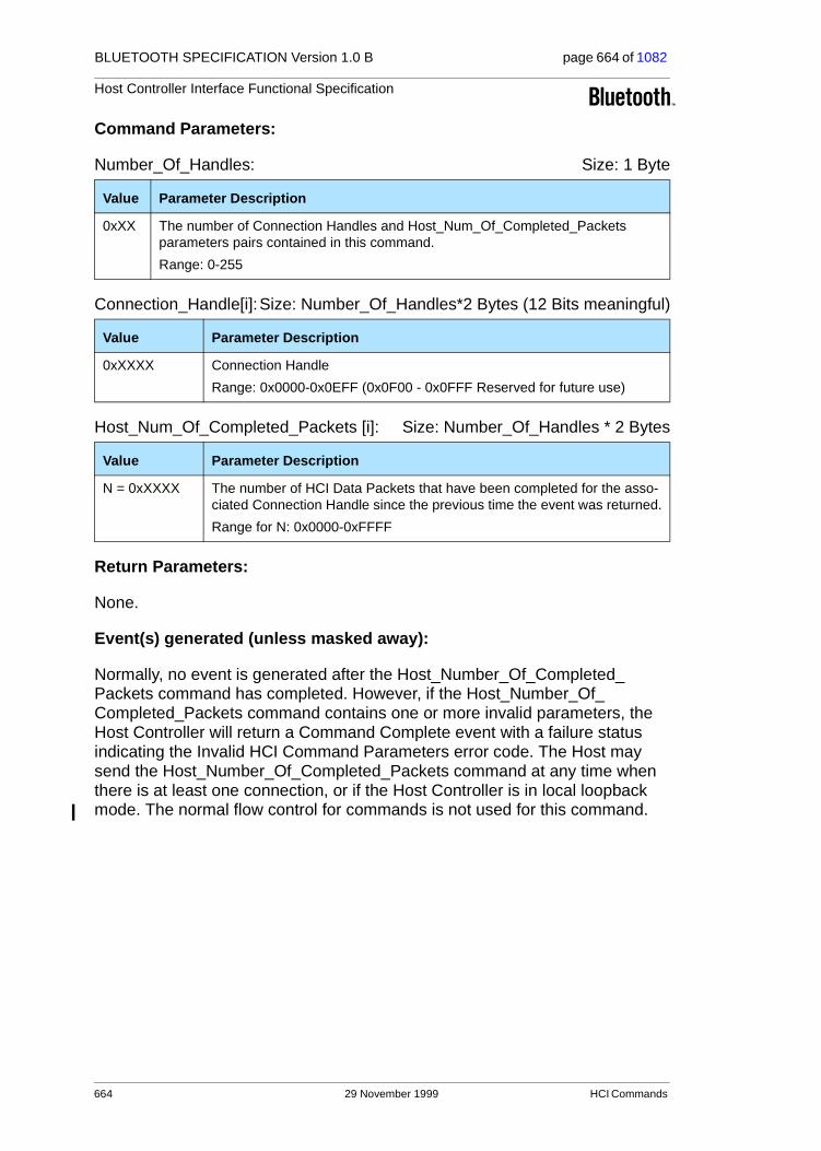
BLUETOOTH SPECIFICATION Version 1.0 B page 664 of 1082
Host Controller Interface Functional Specification
Command Parameters:
Number_Of_Handles: Size: 1 Byte
Connection_Handle[i]:Size: Number_Of_Handles*2 Bytes (12 Bits meaningful)
Host_Num_Of_Completed_Packets [i]: Size: Number_Of_Handles * 2 Bytes
Return Parameters:
None.
Event(s) generated (unless masked away):
Normally, no event is generated after the Host_Number_Of_Completed_Packets command has completed. However, if the Host_Number_Of_Completed_Packets command contains one or more invalid parameters, the Host Controller will return a Command Complete event with a failure status indicating the Invalid HCI Command Parameters error code. The Host may send the Host_Number_Of_Completed_Packets command at any time when there is at least one connection, or if the Host Controller is in local loopback mode. The normal flow control for commands is not used for this command.
Value Parameter Description
0xXX The number of Connection Handles and Host_Num_Of_Completed_Packets parameters pairs contained in this command.
Range: 0-255
Value Parameter Description
0xXXXX Connection Handle
Range: 0x0000-0x0EFF (0x0F00 - 0x0FFF Reserved for future use)
Value Parameter Description
N = 0xXXXX The number of HCI Data Packets that have been completed for the asso-ciated Connection Handle since the previous time the event was returned.
Range for N: 0x0000-0xFFFF
664 29 November 1999 HCI Commands
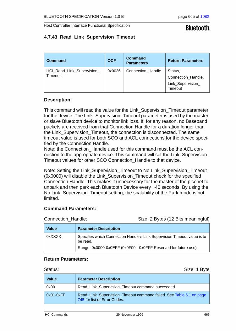
BLUETOOTH SPECIFICATION Version 1.0 B page 665 of 1082
Host Controller Interface Functional Specification
4.7.43 Read_Link_Supervision_Timeout
Description:
This command will read the value for the Link_Supervision_Timeout parameter for the device. The Link_Supervision_Timeout parameter is used by the master or slave Bluetooth device to monitor link loss. If, for any reason, no Baseband packets are received from that Connection Handle for a duration longer than the Link_Supervision_Timeout, the connection is disconnected. The same timeout value is used for both SCO and ACL connections for the device speci-fied by the Connection Handle. Note: the Connection_Handle used for this command must be the ACL con-nection to the appropriate device. This command will set the Link_Supervision_Timeout values for other SCO Connection_Handle to that device.
Note: Setting the Link_Supervision_Timeout to No Link_Supervision_Timeout (0x0000) will disable the Link_Supervision_Timeout check for the specified Connection Handle. This makes it unnecessary for the master of the piconet to unpark and then park each Bluetooth Device every ~40 seconds. By using the No Link_Supervision_Timeout setting, the scalability of the Park mode is not limited.
Command Parameters:
Connection_Handle: Size: 2 Bytes (12 Bits meaningful)
Return Parameters:
Status: Size: 1 Byte
Command OCFCommand Parameters Return Parameters
HCI_Read_Link_Supervision_Timeout
0x0036 Connection_Handle Status,
Connection_Handle,
Link_Supervision_Timeout
Value Parameter Description
0xXXXX Specifies which Connection Handle’s Link Supervision Timeout value is to be read.
Range: 0x0000-0x0EFF (0x0F00 - 0x0FFF Reserved for future use)
Value Parameter Description
0x00 Read_Link_Supervision_Timeout command succeeded.
0x01-0xFF Read_Link_Supervision_Timeout command failed. See Table 6.1 on page 745 for list of Error Codes.
HCI Commands 29 November 1999 665

BLUETOOTH SPECIFICATION Version 1.0 B page 666 of 1082
Host Controller Interface Functional Specification
Connection_Handle: Size: 2 Bytes (12 Bits meaningful)
Link_Supervision_Timeout: Size: 2 Bytes
Event(s) generated (unless masked away):
When the Read_Link_Supervision_Timeout command has completed, a Com-mand Complete event will be generated.
Value Parameter Description
0xXXXX Specifies which Connection Handle’s Link Supervision Timeout value was read.
Range: 0x0000-0x0EFF (0x0F00 - 0x0FFF Reserved for future use)
Value Parameter Description
0x0000 No Link_Supervision_Timeout.
N = 0xXXXX Measured in Number of Baseband slots
Link_Supervision_Timeout = N * 0.625 msec (1 Baseband slot)
Range for N: 0x0001 – 0xFFFF
Time Range: 0.625ms - 40.9 sec
666 29 November 1999 HCI Commands

BLUETOOTH SPECIFICATION Version 1.0 B page 667 of 1082
Host Controller Interface Functional Specification
4.7.44 Write Link_Supervision_Timeout
Description:
This command will write the value for the Link_Supervision_Timeout parameter for the device. The Link_Supervision_Timeout parameter is used by the master or slave Bluetooth device to monitor link loss. If, for any reason, no Baseband packets are received from that Connection_Handle for a duration longer than the Link_Supervision_Timeout, the connection is disconnected. The same timeout value is used for both SCO and ACL connections for the device speci-fied by the Connection_Handle. Note: the Connection_Handle used for this command must be the ACL con-nection to the appropriate device. This command will set the Link_Supervision_Timeout values for other SCO Connection_Handle to that device. Note: Setting the Link_Supervision_Timeout parameter to No Link_Supervision_Timeout (0x0000) will disable the Link_Supervision_Timeout check for the specified Connection Handle. This makes it unnecessary for the master of the piconet to unpark and then park each Bluetooth Device every ~40 seconds. By using the No Link_Supervision_Timeout setting, the scalabil-ity of the Park mode is not limited.
Command Parameters:
Connection_Handle: Size: 2 Bytes (12 Bits meaningful)
Link_Supervision_Timeout: Size: 2 Bytes
Command OCF Command Parameters Return Parameters
HCI_Write_Link_Supervision_Timeout
0x0037 Connection_Handle,
Link_Supervision_Timeout
Status,
Connection_Handle
Value Parameter Description
0xXXXX Specifies which Connection Handle’s Link Supervision Timeout value is to be written.
Range: 0x0000-0x0EFF (0x0F00 - 0x0FFF Reserved for future use)
Value Parameter Description
0x0000 No Link_Supervision_Timeout.
N = 0xXXXX Measured in Number of Baseband slots
Link_Supervision_Timeout = N*0.625 msec (1 Baseband slot)
Range for N: 0x0001 – 0xFFFF
Time Range: 0.625ms – 40.9 sec
Default: N = 0x7D00
Link_Supervision_Timeout = 20 sec
HCI Commands 29 November 1999 667

BLUETOOTH SPECIFICATION Version 1.0 B page 668 of 1082
Host Controller Interface Functional Specification
Return Parameters:
Status: Size: 1 Byte
Connection_Handle: Size: 2 Bytes (12 Bits meaningful)
Event(s) generated (unless masked away):
When the Write_Link_Supervision_Timeout command has completed, a Command Complete event will be generated.
Value Parameter Description
0x00 Write_Link_Supervision_Timeout command succeeded.
0x01-0xFF Write_Link_Supervision_Timeout command failed. See Table 6.1 on page 745 for list of Error Codes.
Value Parameter Description
0xXXXX Specifies which Connection Handle’s Link Supervision Timeout value was written.
Range: 0x0000-0x0EFF (0x0F00 - 0x0FFF Reserved for future use)
668 29 November 1999 HCI Commands
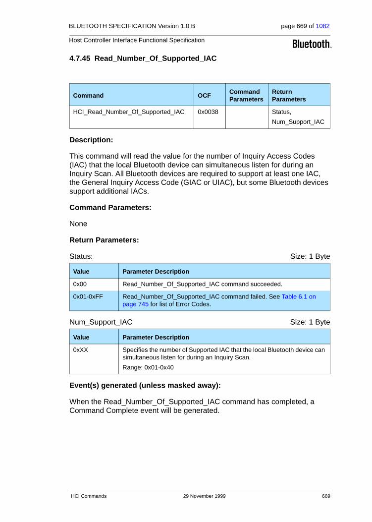
BLUETOOTH SPECIFICATION Version 1.0 B page 669 of 1082
Host Controller Interface Functional Specification
4.7.45 Read_Number_Of_Supported_IAC
Description:
This command will read the value for the number of Inquiry Access Codes (IAC) that the local Bluetooth device can simultaneous listen for during an Inquiry Scan. All Bluetooth devices are required to support at least one IAC, the General Inquiry Access Code (GIAC or UIAC), but some Bluetooth devices support additional IACs.
Command Parameters:
None
Return Parameters:
Status: Size: 1 Byte
Num_Support_IAC Size: 1 Byte
Event(s) generated (unless masked away):
When the Read_Number_Of_Supported_IAC command has completed, a Command Complete event will be generated.
Command OCFCommand Parameters
Return Parameters
HCI_Read_Number_Of_Supported_IAC 0x0038 Status,
Num_Support_IAC
Value Parameter Description
0x00 Read_Number_Of_Supported_IAC command succeeded.
0x01-0xFF Read_Number_Of_Supported_IAC command failed. See Table 6.1 on page 745 for list of Error Codes.
Value Parameter Description
0xXX Specifies the number of Supported IAC that the local Bluetooth device can simultaneous listen for during an Inquiry Scan.
Range: 0x01-0x40
HCI Commands 29 November 1999 669
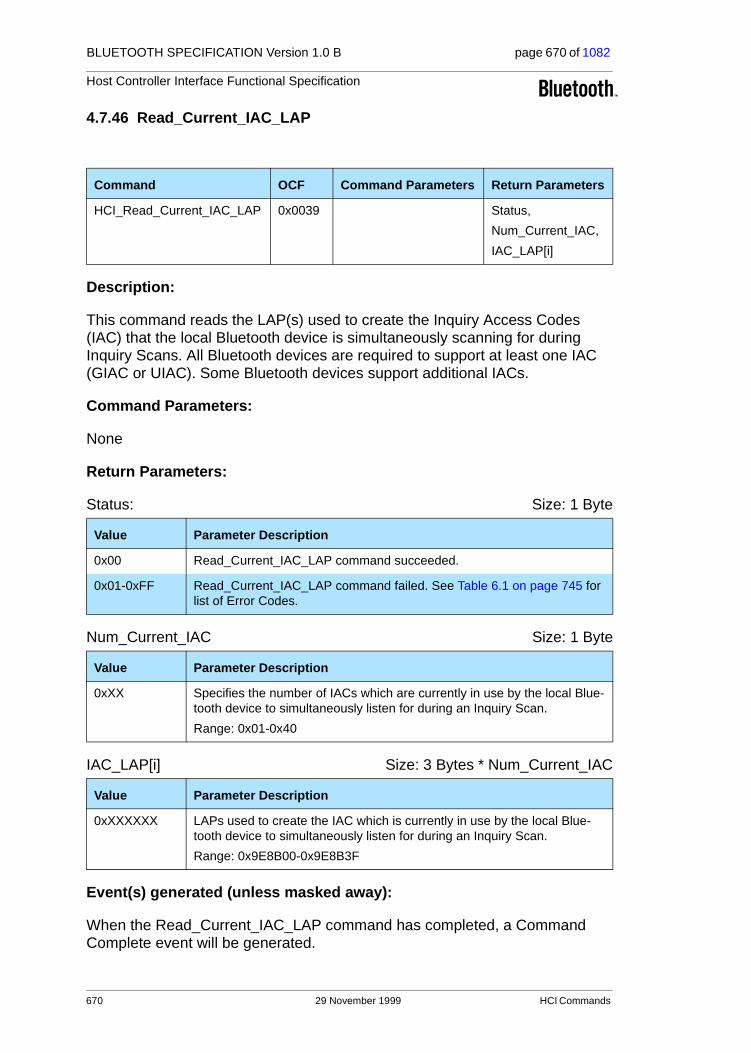
BLUETOOTH SPECIFICATION Version 1.0 B page 670 of 1082
Host Controller Interface Functional Specification
4.7.46 Read_Current_IAC_LAP
Description:
This command reads the LAP(s) used to create the Inquiry Access Codes (IAC) that the local Bluetooth device is simultaneously scanning for during Inquiry Scans. All Bluetooth devices are required to support at least one IAC (GIAC or UIAC). Some Bluetooth devices support additional IACs.
Command Parameters:
None
Return Parameters:
Status: Size: 1 Byte
Num_Current_IAC Size: 1 Byte
IAC_LAP[i] Size: 3 Bytes * Num_Current_IAC
Event(s) generated (unless masked away):
When the Read_Current_IAC_LAP command has completed, a Command Complete event will be generated.
Command OCF Command Parameters Return Parameters
HCI_Read_Current_IAC_LAP 0x0039 Status,
Num_Current_IAC,
IAC_LAP[i]
Value Parameter Description
0x00 Read_Current_IAC_LAP command succeeded.
0x01-0xFF Read_Current_IAC_LAP command failed. See Table 6.1 on page 745 for list of Error Codes.
Value Parameter Description
0xXX Specifies the number of IACs which are currently in use by the local Blue-tooth device to simultaneously listen for during an Inquiry Scan.
Range: 0x01-0x40
Value Parameter Description
0xXXXXXX LAPs used to create the IAC which is currently in use by the local Blue-tooth device to simultaneously listen for during an Inquiry Scan.
Range: 0x9E8B00-0x9E8B3F
670 29 November 1999 HCI Commands
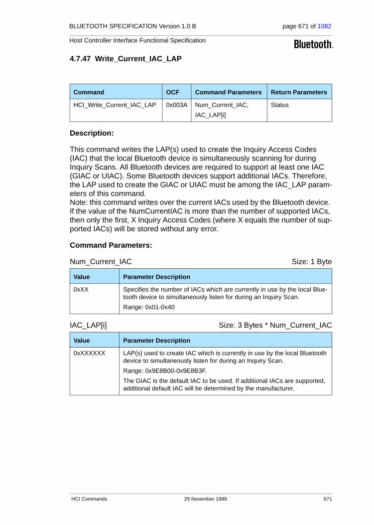
BLUETOOTH SPECIFICATION Version 1.0 B page 671 of 1082
Host Controller Interface Functional Specification
4.7.47 Write_Current_IAC_LAP
Description:
This command writes the LAP(s) used to create the Inquiry Access Codes (IAC) that the local Bluetooth device is simultaneously scanning for during Inquiry Scans. All Bluetooth devices are required to support at least one IAC (GIAC or UIAC). Some Bluetooth devices support additional IACs. Therefore, the LAP used to create the GIAC or UIAC must be among the IAC_LAP param-eters of this command. Note: this command writes over the current IACs used by the Bluetooth device. If the value of the NumCurrentIAC is more than the number of supported IACs, then only the first, X Inquiry Access Codes (where X equals the number of sup-ported IACs) will be stored without any error.
Command Parameters:
Num_Current_IAC Size: 1 Byte
IAC_LAP[i] Size: 3 Bytes * Num_Current_IAC
Command OCF Command Parameters Return Parameters
HCI_Write_Current_IAC_LAP 0x003A Num_Current_IAC,
IAC_LAP[i]
Status
Value Parameter Description
0xXX Specifies the number of IACs which are currently in use by the local Blue-tooth device to simultaneously listen for during an Inquiry Scan.
Range: 0x01-0x40
Value Parameter Description
0xXXXXXX LAP(s) used to create IAC which is currently in use by the local Bluetooth device to simultaneously listen for during an Inquiry Scan.
Range: 0x9E8B00-0x9E8B3F.
The GIAC is the default IAC to be used. If additional IACs are supported, additional default IAC will be determined by the manufacturer.
HCI Commands 29 November 1999 671

BLUETOOTH SPECIFICATION Version 1.0 B page 672 of 1082
Host Controller Interface Functional Specification
Return Parameters:
Status: Size: 1 Byte
Event(s) generated (unless masked away):
When the Write_Current_IAC_LAP command has completed, a Command Complete event will be generated.
Value Parameter Description
0x00 Write_Current_IAC_LAP command succeeded.
0x01-0xFF Write_Current_IAC_LAP command failed. See Table 6.1 on page 745 for list of Error Codes.
672 29 November 1999 HCI Commands

BLUETOOTH SPECIFICATION Version 1.0 B page 673 of 1082
Host Controller Interface Functional Specification
4.7.48 Read_Page_Scan_Period_Mode
Description:
This command is used to read the mandatory Page_Scan_Period_Mode of the local Bluetooth device. Every time an inquiry response message is sent, the Bluetooth device will start a timer (T_mandatory_pscan), the value of which is dependent on the Page_Scan_Period_Mode. As long as this timer has not expired, the Bluetooth device will use the Page_Scan_Period_Mode for all fol-lowing page scans. Note: the timer T_mandatory_pscan will be reset at each new inquiry response. For details see the “Baseband Specification” on page 33. (Keyword: SP-Mode, FHS-Packet, T_mandatory_pscan, Inquiry-Response).
After transmitting one or more inquiry response (FHS) packets as a result of the inquiry scan process, the local Bluetooth device is allowed to enter the page scan state using mandatory page scan mode regardless of the setting of the Scan_Enable parameter.
Command Parameters:
None
Return Parameters:
Status: Size: 1 Byte
Page_Scan_Period_Mode: Size: 1 Byte
Command OCFCommand Parameters Return Parameters
HCI_Read_Page_Scan_Period_Mode
0x003B Status,
Page_Scan_Period_Mode
Value Parameter Description
0x00 Read_Page_Scan_Period_Mode command succeeded.
0x01-0xFF Read_Page_Scan_Period_Mode command failed. See Table 6.1 on page 745 for list of Error Codes.
Value Parameter Description
0x00 P0
0x01 P1
0x02 P2
0x03-0xFF Reserved.
HCI Commands 29 November 1999 673
BLUETOOTH SPECIFICATION Version 1.0 B page 674 of 1082
Host Controller Interface Functional Specification
Event(s) generated (unless masked away):
When the Read_Page_Scan_Period_Mode command has completed, a Com-mand Complete event will be generated.
674 29 November 1999 HCI Commands
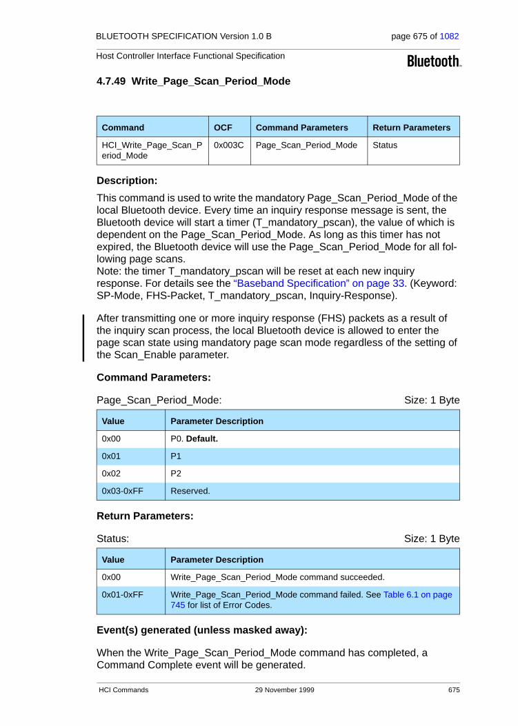
BLUETOOTH SPECIFICATION Version 1.0 B page 675 of 1082
Host Controller Interface Functional Specification
4.7.49 Write_Page_Scan_Period_Mode
Description:
This command is used to write the mandatory Page_Scan_Period_Mode of the local Bluetooth device. Every time an inquiry response message is sent, the Bluetooth device will start a timer (T_mandatory_pscan), the value of which is dependent on the Page_Scan_Period_Mode. As long as this timer has not expired, the Bluetooth device will use the Page_Scan_Period_Mode for all fol-lowing page scans. Note: the timer T_mandatory_pscan will be reset at each new inquiry response. For details see the “Baseband Specification” on page 33. (Keyword: SP-Mode, FHS-Packet, T_mandatory_pscan, Inquiry-Response).
After transmitting one or more inquiry response (FHS) packets as a result of the inquiry scan process, the local Bluetooth device is allowed to enter the page scan state using mandatory page scan mode regardless of the setting of the Scan_Enable parameter.
Command Parameters:
Page_Scan_Period_Mode: Size: 1 Byte
Return Parameters:
Status: Size: 1 Byte
Event(s) generated (unless masked away):
When the Write_Page_Scan_Period_Mode command has completed, a Command Complete event will be generated.
Command OCF Command Parameters Return Parameters
HCI_Write_Page_Scan_Period_Mode
0x003C Page_Scan_Period_Mode Status
Value Parameter Description
0x00 P0. Default.
0x01 P1
0x02 P2
0x03-0xFF Reserved.
Value Parameter Description
0x00 Write_Page_Scan_Period_Mode command succeeded.
0x01-0xFF Write_Page_Scan_Period_Mode command failed. See Table 6.1 on page 745 for list of Error Codes.
HCI Commands 29 November 1999 675

BLUETOOTH SPECIFICATION Version 1.0 B page 676 of 1082
Host Controller Interface Functional Specification
4.7.50 Read_Page_Scan_Mode
Description:
This command is used to read the default page scan mode of the local Bluetooth device. The Page_Scan_Mode parameter indicates the page scan mode that is used for default page scan. Currently one mandatory page scan mode and three optional page scan modes are defined. Following an inquiry response, if the Baseband timer T_mandatory_pscan has not expired, the mandatory page scan mode must be applied. For details see the “Baseband Specification” on page 33 (Keyword: Page-Scan-Mode, FHS-Packet, T_mandatory_pscan)
Command Parameters:
None
Return Parameters:
Status: Size: 1 Byte
Page_Scan_Mode: Size: 1 Byte
Event(s) generated (unless masked away):
When the Read_Page_Scan_Mode command has completed, a Command Complete event will be generated.
Command OCFCommand Parameters Return Parameters
HCI_Read_Page_Scan_Mode 0x003D Status,
Page_Scan_Mode
Value Parameter Description
0x00 Read_Page_Scan_Mode command succeeded.
0x01-0xFF Read_Page_Scan_Mode command failed. See Table 6.1 on page 745 for list of Error Codes.
Value Parameter Description
0x00 Mandatory Page Scan Mode
0x01 Optional Page Scan Mode I
0x02 Optional Page Scan Mode II
0x03 Optional Page Scan Mode III
0x04-0xFF Reserved
676 29 November 1999 HCI Commands

BLUETOOTH SPECIFICATION Version 1.0 B page 677 of 1082
Host Controller Interface Functional Specification
4.7.51 Write_Page_Scan_Mode
Description:
This command is used to write the default page scan mode of the local Bluetooth device. The Page_Scan_Mode parameter indicates the page scan mode that is used for the default page scan. Currently, one mandatory page scan mode and three optional page scan modes are defined. Following an inquiry response, if the Baseband timer T_mandatory_pscan has not expired, the mandatory page scan mode must be applied. For details see the “Base-band Specification” on page 33. (Keyword: Page-Scan-Mode, FHS-Packet, T_mandatory_pscan).
Command Parameters:
Page_Scan_Mode: Size: 1 Byte
Return Parameters:
Status: Size: 1 Byte
Event(s) generated (unless masked away):
When the Write_Page_Scan_Mode command has completed, a Command Complete event will be generated.
Command OCF Command ParametersReturn Parameters
HCI_Write_Page_Scan_Mode 0x003E Page_Scan_Mode Status
Value Parameter Description
0x00 Mandatory Page Scan Mode. Default.
0x01 Optional Page Scan Mode I
0x02 Optional Page Scan Mode II
0x03 Optional Page Scan Mode III
0x04-0xFF Reserved.
Value Parameter Description
0x00 Write_Page_Scan_Mode command succeeded.
0x01-0xFF Write_Page_Scan_Mode command failed. See Table 6.1 on page 745 for list of Error Codes.
HCI Commands 29 November 1999 677

BLUETOOTH SPECIFICATION Version 1.0 B page 678 of 1082
Host Controller Interface Functional Specification
4.8 INFORMATIONAL PARAMETERS
The Informational Parameters are fixed by the manufacturer of the Bluetooth hardware. These parameters provide information about the Bluetooth device and the capabilities of the Host Controller, Link Manager, and Baseband. The host device cannot modify any of these parameters. For Informational Parame-ters Commands, the OGF is defined as 0x04
Command Command Summary Description
Read_Local_Version_Information The Read_Local_Version_Information command will read the values for the version information for the local Bluetooth device.
Read_Local_Supported_Features The Read_Local_Supported_Features command requests a list of the supported features for the local device.
Read_Buffer_Size The Read_Buffer_Size command returns the size of the HCI buffers. These buffers are used by the Host Controller to buffer data that is to be transmit-ted.
Read_Country_Code The Read_Country_Code command will read the value for the Country Code status parameter. The Country Code defines which range of frequency band of the ISM 2.4 GHz band will be used by the device.
Read_BD_ADDR The Read_BD_ADDR command will read the value for the BD_ADDR parameter. The BD_ADDR is a 48-bit unique identifier for a Bluetooth device.
678 29 November 1999 HCI Commands

BLUETOOTH SPECIFICATION Version 1.0 B page 679 of 1082
Host Controller Interface Functional Specification
4.8.1 Read_Local_Version_Information
Description:
This command will read the values for the version information for the local Bluetooth device. The version information consists of two parameters: the ver-sion and revision parameters.
The version parameter defines the major hardware version of the Bluetooth hardware. The version parameter only changes when new versions of the Bluetooth hardware are produced for new Bluetooth SIG specifications. The version parameter is controlled by the SIG.
The revision parameter should be controlled by the manufacturer and should be changed as needed. The Manufacturer_Name parameter indicates the manufacturer of the local Bluetooth module as specified by the LMP definition of this parameter. The subversion parameter should be controlled by the manu-facturer and should be changed as needed. The subversion parameter defines the various revisions that each version of the Bluetooth hardware will go through as design processes change and errors are fixed. This allows the soft-ware to determine what Bluetooth hardware is being used, and to work around various bugs in the hardware if necessary.
Command Parameters:
None.
Return Parameters:
Status: Size: 1 Byte
Command OCFCommand Parameters Return Parameters
HCI_Read_Local_Version_
Information
0x0001 Status,
HCI Version,
HCI Revision,
LMP Version,
Manufacturer_Name,
LMP Subversion
Value Parameter Description
0x00 Read_Local_Version_Information command succeeded.
0x01-0xFF Read_Local_Version_Information command failed. See Table 6.1 on page 745 for list of Error Codes.
HCI Commands 29 November 1999 679

BLUETOOTH SPECIFICATION Version 1.0 B page 680 of 1082
Host Controller Interface Functional Specification
HCI_Version: Size: 1 Byte
HCI_Revision: Size: 2 Bytes
LMP_Version: Size: 1 Byte
Manufacturer_Name: Size: 2 Bytes
LMP_Subversion: Size: 2 Bytes
Event(s) generated (unless masked away):
When the Read_Local_Version_Information command has completed, a Command Complete event will be generated.
Value Parameter Description
0xXX Version of the Current HCI in the Bluetooth hardware.
0x00: Bluetooth HCI Specification 1.0
0x01-0xFF: Reserved
Value Parameter Description
0xXXXX Revision of the Current HCI in the Bluetooth hardware.
Value Parameter Description
0xXX Version of the Current LMP in the Bluetooth Hardware, see Table 5.2 on page 231 in the Link Manager Protocol for assigned values (VersNr).
Value Parameter Description
0xXXXX Manufacturer Name of the Bluetooth Hardware, see Table 5.2 on page 231 in the Link Manager Protocol for assigned values (CompId).
Value Parameter Description
0xXXXX Subversion of the Current LMP in the Bluetooth Hardware, see Table 5.2 on page 231 in the Link Manager Protocol for assigned values (SubVersNr).
680 29 November 1999 HCI Commands

BLUETOOTH SPECIFICATION Version 1.0 B page 681 of 1082
Host Controller Interface Functional Specification
4.8.2 Read_Local_Supported_Features
Description:
This command requests a list of the supported features for the local device. This command will return a list of the LMP features. For details see “Link Man-ager Protocol” on page 185.
Command Parameters:
None.
Return Parameters:
Status: Size: 1 Byte
LMP_Features: Size: 8 Bytes
Event(s) generated (unless masked away):
When the Read_Local_Supported_Features command has completed, a Command Complete event will be generated.
Command OCFCommand Parameters Return Parameters
HCI_Read_Local_Supported_Features 0x0003 Status,
LMP_Features
Value Parameter Description
0x00 Read_Local_Supported_Features command succeeded.
0x01-0xFF Read_Local_Supported_Features command failed. See Table 6.1 on page 745 for list of Error Codes.
Value Parameter Description
0xXXXXXXXXXXXXXXXX
Bit Mask List of LMP features. For details see “Link Manager Protocol” on page 185
HCI Commands 29 November 1999 681

BLUETOOTH SPECIFICATION Version 1.0 B page 682 of 1082
Host Controller Interface Functional Specification
4.8.3 Read_Buffer_Size
Description:
The Read_Buffer_Size command is used to read the maximum size of the data portion of HCI ACL and SCO Data Packets sent from the Host to the Host Con-troller. The Host will segment the data to be transmitted from the Host to the Host Controller according to these sizes, so that the HCI Data Packets will con-tain data with up to these sizes. The Read_Buffer_Size command also returns the total number of HCI ACL and SCO Data Packets that can be stored in the data buffers of the Host Controller. The Read_Buffer_Size command must be issued by the Host before it sends any data to the Host Controller.
The HC_ACL_Data_Packet_Length return parameter will be used to determine the size of the L2CAP segments contained in ACL Data Packets, which are transferred from the Host to the Host Controller to be broken up into baseband packets by the Link Manager. The HC_SCO_Data_Packet_Length return parameter is used to determine the maximum size of HCI SCO Data Packets. Both the Host and the Host Controller must support command and event pack-ets, where the data portion (excluding header) contained in the packets is 255 bytes in size. The HC_Total_Num_ACL_Data_Packets return parameter con-tains the total number of HCI ACL Data Packets that can be stored in the data buffers of the Host Controller. The Host will determine how the buffers are to be divided between different Connection Handles. The HC_Total_Num_SCO_Data_Packets return parameter gives the same information but for HCI SCO Data Packets. Note: the HC_ACL_Data_Packet_Length and HC_SCO_Data_Packet_Length return parameters do not include the length of the HCI Data Packet header.
Command Parameters:
None.
Command OCFCommand Parameters Return Parameters
HCI_Read_Buffer_Size 0x0005 Status,
HC_ACL_Data_Packet_Length,
HC_SCO_Data_Packet_Length, HC_
Total_Num_ACL_Data_Packets,
HC_Total_Num_SCO_Data_Packets
682 29 November 1999 HCI Commands

BLUETOOTH SPECIFICATION Version 1.0 B page 683 of 1082
Host Controller Interface Functional Specification
Return Parameters:
Status: Size: 1 Byte
HC_ACL_Data_Packet_Length: Size: 2 Bytes
HC_SCO_Data_Packet_Length: Size: 1 Byte
HC_Total_Num_ACL_Data_Packets: Size: 2 Bytes
HC_Total_Num_SCO_Data_Packets: Size: 2 Bytes
Event(s) generated (unless masked away):
When the Read_Buffer_Size command has completed, a Command Complete event will be generated.
Value Parameter Description
0x00 Read_Buffer_Size command succeeded.
0x01-0xFF Read_Buffer_Size command failed. See Table 6.1 on page 745 for list of Error Codes.
Value Parameter Description
0xXXXX Maximum length (in bytes) of the data portion of each HCI ACL Data Packet that the Host Controller is able to accept.
Value Parameter Description
0xXX Maximum length (in bytes) of the data portion of each HCI SCO Data Packet that the Host Controller is able to accept.
Value Parameter Description
0xXXXX Total number of HCI ACL Data Packets that can be stored in the data buffers of the Host Controller.
Value Parameter Description
0xXXXX Total number of HCI SCO Data Packets that can be stored in the data buffers of the Host Controller.
HCI Commands 29 November 1999 683

BLUETOOTH SPECIFICATION Version 1.0 B page 684 of 1082
Host Controller Interface Functional Specification
4.8.4 Read_Country_Code
Description:
This command will read the value for the Country_Code return parameter. The Country_Code defines which range of frequency band of the ISM 2.4 GHz band will be used by the device. Each country has local regulatory bodies regulating which ISM 2.4 GHz frequency ranges can be used.
Command Parameters:
None.
Return Parameters:
Status: Size: 1 Byte
Country_Code: Size: 1 Byte
*. Except Spain and France
Event(s) generated (unless masked away):
When the Read_Country_Code command has completed, a Command Complete event will be generated.
Command OCF Command Parameters Return Parameters
HCI_Read_Country_Code 0x0007 Status,
Country_Code
Value Parameter Description
0x00 Read_Country_Code command succeeded.
0x01-0xFF Read_Country_Code command failed. See Table 6.1 on page 745 for list of Error Codes.
Value Parameter Description
0x00 North America & Europe*
0x01 France
0x02 Spain
0x03 Japan
0x04-FF Reserved for Future Use.
684 29 November 1999 HCI Commands

BLUETOOTH SPECIFICATION Version 1.0 B page 685 of 1082
Host Controller Interface Functional Specification
4.8.5 Read_BD_ADDR
Description:
This command will read the value for the BD_ADDR parameter. The BD_ADDR is a 48-bit unique identifier for a Bluetooth device. See the “Baseband Specification” on page 33 for details of how BD_ADDR is used.
Command Parameters:
None.
Return Parameters:
Status: Size: 1 Byte
BD_ADDR: Size: 6 Bytes
Event(s) generated (unless masked away):
When the Read_BD_ADDR command has completed, a Command Complete event will be generated.
Command OCFCommand Parameters Return Parameters
HCI_Read_BD_ADDR 0x0009 Status,
BD_ADDR
Value Parameter Description
0x00 Read_BD_ADDR command succeeded.
0x01-0xFF Read_BD_ADDR command failed. See Table 6.1 on page 745 for list of Error Codes.
Value Parameter Description
0xXXXXXXXXXXXX BD_ADDR of the Device
HCI Commands 29 November 1999 685

BLUETOOTH SPECIFICATION Version 1.0 B page 686 of 1082
Host Controller Interface Functional Specification
4.9 STATUS PARAMETERS
The Host Controller modifies all status parameters. These parameters provide information about the current state of the Host Controller, Link Manager, and Baseband. The host device cannot modify any of these parameters other than to reset certain specific parameters. For the Status and baseband, the OGF is defined as 0x05
Command Command Summary Description
Read_Failed_Contact_Counter The Read_Failed_Contact_Counter will read the value for the Failed_Contact_Counter parameter for a particular connection to another device. The Failed_Contact_Counter records the number of consecutive incidents in which either the slave or master didn’t respond after the flush timeout had expired, and the L2CAP packet that was currently being transmitted was automatically ‘flushed’.
Reset_Failed_Contact_Counter The Reset_Failed_Contact_Counter will reset the value for the Failed_Contact_Counter parameter for a particular connection to another device. The Failed_Contact_Counter records the number of consecutive incidents in which either the slave or master didn’t respond after the flush timeout had expired and the L2CAP packet that was currently being transmitted was automatically ‘flushed’.
Get_Link_Quality The Get_Link_Quality command will read the value for the Link_Quality for the specified Connection Handle.
Read_RSSI The Read_RSSI command will read the value for the Received Signal Strength Indication (RSSI) for a connection handle to another Bluetooth device.
686 29 November 1999 HCI Commands

BLUETOOTH SPECIFICATION Version 1.0 B page 687 of 1082
Host Controller Interface Functional Specification
4.9.1 Read_Failed_Contact_Counter
Description:
This command will read the value for the Failed_Contact_Counter parameter for a particular connection to another device. The Connection_Handle must be a Connection_Handle for an ACL connection. The Failed_Contact_Counter records the number of consecutive incidents in which either the slave or master didn’t respond after the flush timeout had expired, and the L2CAP packet that was currently being transmitted was automatically ‘flushed’. When this occurs, the Failed_Contact_Counter is incremented by 1. The Failed_Contact_Counter for a connection is reset to zero on the following conditions:
1. When a new connection is established
2. When the Failed_Contact_Counter is > zero and an L2CAP packet is acknowledged for that connection
3. When the Reset_Failed_Contact_Counter command has been issued
Command Parameters:
Connection_Handle: Size: 2 Bytes (12 Bits meaningful)
Return Parameters:
Status: Size: 1 Byte
Command OCF Command Parameters Return Parameters
HCI_Read_Failed_Contact_Counter
0x0001 Connection_Handle Status,
Connection_Handle,
Failed_Contact_Counter
Value Parameter Description
0xXXXX The Connection Handle for the Connection for which the Failed Contact Counter should be read.
Range: 0x0000-0x0EFF (0x0F00 - 0x0FFF Reserved for future use)
Value Parameter Description
0x00 Read_Failed_Contact_Counter command succeeded.
0x01-0xFF Read_Failed_Contact_Counter command failed. See Table 6.1 on page 745 for list of Error Codes.
HCI Commands 29 November 1999 687

BLUETOOTH SPECIFICATION Version 1.0 B page 688 of 1082
Host Controller Interface Functional Specification
Connection_Handle: Size: 2 Bytes (12 Bits meaningful)
Failed_Contact_Counter: Size: 2 Bytes
Event(s) generated (unless masked away):
When the Read_Failed_Contact_Counter command has completed, a Com-mand Complete event will be generated.
Value Parameter Description
0xXXXX The Connection Handle for the Connection for which the Failed Contact Counter has been read.
Range: 0x0000-0x0EFF (0x0F00 - 0x0FFF Reserved for future use)
Value Parameter Description
0xXXXX Number of consecutive failed contacts for a connection corresponding to the connection handle.
688 29 November 1999 HCI Commands

BLUETOOTH SPECIFICATION Version 1.0 B page 689 of 1082
Host Controller Interface Functional Specification
4.9.2 Reset_Failed_Contact_Counter
Description:
This command will reset the value for the Failed_Contact_Counter parameter for a particular connection to another device. The Connection_Handle must be a Connection_Handle for an ACL connection. The Failed_Contact_Counter records the number of consecutive incidents in which either the slave or master didn’t respond after the flush timeout had expired, and the L2CAP packet that was currently being transmitted was automatically ‘flushed’. When this occurs, the Failed_Contact_Counter is incremented by 1.The Failed_Contact_Counter for a connection is reset to zero on the following conditions:
1. When a new connection is established
2. When the Failed_Contact_Counter is > zero and an L2CAP packet is acknowledged for that connection
3. When the Reset_Failed_Contact_Counter command has been issued
Command Parameters:
Connection_Handle: Size: 2 Bytes (12 Bits meaningful)
Return Parameters:
Status: Size: 1 Byte
Command OCF Command Parameters Return Parameters
HCI_Reset_Failed_Contact_Counter
0x0002 Connection_Handle Status,
Connection_Handle
Value Parameter Description
0xXXXX The Connection Handle for the Connection for which the Failed Contact Counter should be reset.
Range: 0x0000-0x0EFF (0x0F00 - 0x0FFF Reserved for future use)
Value Parameter Description
0x00 Reset_Failed_Contact_Counter command succeeded.
0x01-0xFF Reset_Failed_Contact_Counter command failed. See Table 6.1 on page 745 for list of Error Codes.
HCI Commands 29 November 1999 689
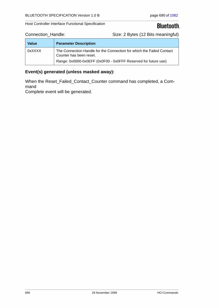
BLUETOOTH SPECIFICATION Version 1.0 B page 690 of 1082
Host Controller Interface Functional Specification
Connection_Handle: Size: 2 Bytes (12 Bits meaningful)
Event(s) generated (unless masked away):
When the Reset_Failed_Contact_Counter command has completed, a Com-mand Complete event will be generated.
Value Parameter Description
0xXXXX The Connection Handle for the Connection for which the Failed Contact Counter has been reset.
Range: 0x0000-0x0EFF (0x0F00 - 0x0FFF Reserved for future use)
690 29 November 1999 HCI Commands

BLUETOOTH SPECIFICATION Version 1.0 B page 691 of 1082
Host Controller Interface Functional Specification
4.9.3 Get_Link_Quality
Description:
This command will return the value for the Link_Quality for the specified Con-nection Handle. The Connection_Handle must be a Connection_Handle for an ACL connection. This command will return a Link_Quality value from 0-255, which represents the quality of the link between two Bluetooth devices. The higher the value, the better the link quality is. Each Bluetooth module vendor will determine how to measure the link quality.
Command Parameters:
Connection_Handle: Size: 2 Bytes (12 Bits meaningful)
Return Parameters:
Status: Size: 1 Byte
Connection_Handle: Size: 2 Bytes (12 Bits meaningful)
Command OCF Command Parameters Return Parameters
HCI_Get_Link_Quality 0x0003 Connection_Handle Status,
Connection_Handle,
Link_Quality
Value Parameter Description
0xXXXX The Connection Handle for the connection for which link quality parame-ters are to be read.
Range: 0x0000-0x0EFF (0x0F00 - 0x0FFF Reserved for future use)
Value Parameter Description
0x00 Get_Link_Quality command succeeded.
0x01-0xFF Get_Link_Quality command failed.See Table 6.1 on page 745 for list of Error Codes.
Value Parameter Description
0xXXXX The Connection Handle for the connection for which the link quality parameter has been read.
Range: 0x0000-0x0EFF (0x0F00 - 0x0FFF Reserved for future use)
HCI Commands 29 November 1999 691

BLUETOOTH SPECIFICATION Version 1.0 B page 692 of 1082
Host Controller Interface Functional Specification
Link_Quality: Size: 1 Byte
Event(s) generated (unless masked away):
When the Get_Link_Quality command has completed, a Command Complete event will be generated.
Value Parameter Description
0xXX The current quality of the Link connection between the local device and the remote device specified by the Connection Handle
Range: 0x00 – 0xFF
The higher the value, the better the link quality is.
692 29 November 1999 HCI Commands

BLUETOOTH SPECIFICATION Version 1.0 B page 693 of 1082
Host Controller Interface Functional Specification
4.9.4 Read_RSSI
Description:
This command will read the value for the difference between the measured Received Signal Strength Indication (RSSI) and the limits of the Golden Receive Power Range (see Radio Specification Section 4.7 on page 26) for a connection handle to another Bluetooth device. The Connection_Handle must be a Connection_Handle for an ACL connection. Any positive RSSI value returned by the Host Controller indicates how many dB the RSSI is above the upper limit, any negative value indicates how many dB the RSSI is below the lower limit. The value zero indicates that the RSSI is inside the Golden Receive Power Range. Note: how accurate the dB values will be depends on the Bluetooth hardware. The only requirements for the hardware are that the Bluetooth device is able to tell whether the RSSI is inside, above or below the Golden Device Power Range.
Command Parameters:
Connection_Handle: Size: 2 Bytes (12 Bits meaningful)
Return Parameters:
Status: Size: 1 Byte
Connection_Handle: Size: 2 Bytes (12 Bits meaningful)
Command OCF Command Parameters Return Parameters
HCI_Read_RSSI 0x0005 Connection_Handle Status,
Connection_Handle,RSSI
Value Parameter Description
0xXXXX The Connection Handle for the Connection for which the RSSI is to be read.
Range: 0x0000-0x0EFF (0x0F00 - 0x0FFF Reserved for future use)
Value Parameter Description
0x00 Read_RSSI command succeeded.
0x01-0xFF Read_RSSI command failed. See Table 6.1 on page 745 for list of Error Codes.
Value Parameter Description
0xXXXX The Connection Handle for the Connection for which the RSSI has been read.
Range: 0x0000-0x0EFF (0x0F00 - 0x0FFF Reserved for future use)
HCI Commands 29 November 1999 693

BLUETOOTH SPECIFICATION Version 1.0 B page 694 of 1082
Host Controller Interface Functional Specification
RSSI: Size: 1 Byte
Event(s) generated (unless masked away):
When the Read_RSSI command has completed, a Command Complete event will be generated.
Value Parameter Description
N = 0xXX Size: 1 Byte (signed integer)
Range: -128 ≤ N ≤ 127
Units: dB
694 29 November 1999 HCI Commands
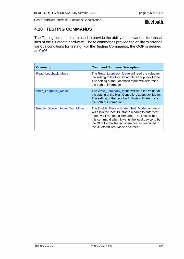
BLUETOOTH SPECIFICATION Version 1.0 B page 695 of 1082
Host Controller Interface Functional Specification
4.10 TESTING COMMANDS
The Testing commands are used to provide the ability to test various functional-ities of the Bluetooth hardware. These commands provide the ability to arrange various conditions for testing. For the Testing Commands, the OGF is defined as 0x06
Command Command Summary Description
Read_Loopback_Mode The Read_Loopback_Mode will read the value for the setting of the Host Controllers Loopback Mode. The setting of the Loopback Mode will determine the path of information.
Write_Loopback_Mode The Write_Loopback_Mode will write the value for the setting of the Host Controllers Loopback Mode. The setting of the Loopback Mode will determine the path of information.
Enable_Device_Under_Test_Mode The Enable_Device_Under_Test_Mode command will allow the local Bluetooth module to enter test mode via LMP test commands. The Host issues this command when it wants the local device to be the DUT for the Testing scenarios as described in the Bluetooth Test Mode document.
HCI Commands 29 November 1999 695

BLUETOOTH SPECIFICATION Version 1.0 B page 696 of 1082
Host Controller Interface Functional Specification
4.10.1 Read_Loopback_Mode
Description:
This command will read the value for the setting of the Host Controller’s Loop-back Mode. The setting of the Loopback Mode will determine the path of infor-mation. In Non-testing Mode operation, the Loopback Mode is set to Non-testing Mode and the path of the information is as specified by the Bluetooth specifications. In Local Loopback Mode, every Data Packet (ACL and SCO) and Command Packet that is sent from the Host to the Host Controller is sent back with no modifications by the Host Controller, as shown in Fig. 4.5 on page 697.
When the Bluetooth Host Controller enters Local Loopback Mode, it shall respond with four Connection Complete events, one for an ACL channel and three for SCO channels, so that the Host gets connection handles to use when sending ACL and SCO data. When in Local Loopback Mode the Host Control-ler loops back commands and data to the Host. The Loopback Command event is used to loop back commands that the Host sends to the Host Control-ler.
There are some commands that are not looped back in Local Loopback Mode: Reset, Set_Host_Controller_To_Host_Flow_Control, Host_Buffer_Size, Host_Number_Of_Completed_Packets, Read_Buffer_Size, Read_Loopback_Mode and Write_Loopback_Mode.These commands should be executed in the way they are normally executed. The commands Reset and Write_Loopback_Mode can be used to exit local loopback mode. If Write_Loopback_Mode is used to exit Local Loopback Mode, four Disconnection Complete events should be sent to the Host, corresponding to the Connection Complete events that were sent when entering Local Loopback Mode. Furthermore, no connections are allowed in Local Loopback mode. If there is a connection and there is an attempt to set the device to Local Loopback Mode, the attempt will be refused. When the device is in Local Loopback Mode, the Host Controller will refuse incoming connection attempts. This allows the Host Controller Transport Layer to be tested without any other variables.
If a device is set to Remote Loopback Mode, it will send back all data (ACL and SCO) that comes over the air, and it will only allow a maximum of one ACL con-nection and three SCO connections – and these should be all to the same remote device. If there already are connections to more than one remote device and there is an attempt to set the local device to Remote Loopback Mode, the attempt will be refused. See Fig. 4.6 on page 697 where the right-most device is set to Remote Loopback Mode and the leftmost device is set to
Command OCF Command Parameters Return Parameters
HCI_Read_Loopback_Mode 0x0001 Status,
Loopback_Mode
696 29 November 1999 HCI Commands

BLUETOOTH SPECIFICATION Version 1.0 B page 697 of 1082
Host Controller Interface Functional Specification
Non-testing Mode. This allows the Bluetooth Air link to be tested without any other variables.
Figure 4.5: Local Loopback Mode
Figure 4.6: Remote Loopback Mode
Command Parameters:
None.
Bluetooth Host #1
Bluetooth Hardware
HCI Driver
HCI Firmware
Baseband Controller
SoftwareFirmware
Hardware
Link ManagerFirmware
LoopbackData Path
Bluetooth Host #1
Bluetooth Hardware
HCI Driver
HCI Firmware
Baseband Controller
SoftwareFirmware
HardwareLoopbackData Path
Bluetooth Host #2
Bluetooth Hardware
HCI Driver
HCI Firmware
Baseband Controller
Link ManagerFirmware
Link ManagerFirmware
HCI Commands 29 November 1999 697
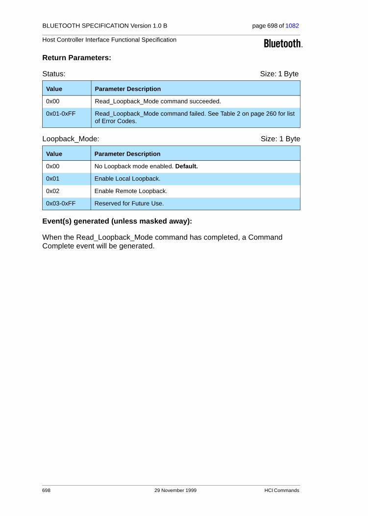
BLUETOOTH SPECIFICATION Version 1.0 B page 698 of 1082
Host Controller Interface Functional Specification
Return Parameters:
Status: Size: 1 Byte
Loopback_Mode: Size: 1 Byte
Event(s) generated (unless masked away):
When the Read_Loopback_Mode command has completed, a Command Complete event will be generated.
Value Parameter Description
0x00 Read_Loopback_Mode command succeeded.
0x01-0xFF Read_Loopback_Mode command failed. See Table 2 on page 260 for list of Error Codes.
Value Parameter Description
0x00 No Loopback mode enabled. Default.
0x01 Enable Local Loopback.
0x02 Enable Remote Loopback.
0x03-0xFF Reserved for Future Use.
698 29 November 1999 HCI Commands
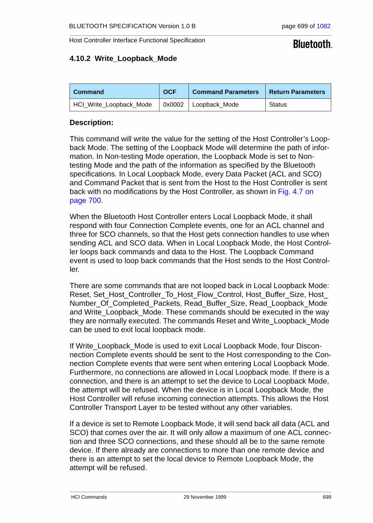
BLUETOOTH SPECIFICATION Version 1.0 B page 699 of 1082
Host Controller Interface Functional Specification
4.10.2 Write_Loopback_Mode
Description:
This command will write the value for the setting of the Host Controller’s Loop-back Mode. The setting of the Loopback Mode will determine the path of infor-mation. In Non-testing Mode operation, the Loopback Mode is set to Non-testing Mode and the path of the information as specified by the Bluetooth specifications. In Local Loopback Mode, every Data Packet (ACL and SCO) and Command Packet that is sent from the Host to the Host Controller is sent back with no modifications by the Host Controller, as shown in Fig. 4.7 on page 700.
When the Bluetooth Host Controller enters Local Loopback Mode, it shall respond with four Connection Complete events, one for an ACL channel and three for SCO channels, so that the Host gets connection handles to use when sending ACL and SCO data. When in Local Loopback Mode, the Host Control-ler loops back commands and data to the Host. The Loopback Command event is used to loop back commands that the Host sends to the Host Control-ler.
There are some commands that are not looped back in Local Loopback Mode: Reset, Set_Host_Controller_To_Host_Flow_Control, Host_Buffer_Size, Host_Number_Of_Completed_Packets, Read_Buffer_Size, Read_Loopback_Mode and Write_Loopback_Mode. These commands should be executed in the way they are normally executed. The commands Reset and Write_Loopback_Mode can be used to exit local loopback mode.
If Write_Loopback_Mode is used to exit Local Loopback Mode, four Discon-nection Complete events should be sent to the Host corresponding to the Con-nection Complete events that were sent when entering Local Loopback Mode. Furthermore, no connections are allowed in Local Loopback mode. If there is a connection, and there is an attempt to set the device to Local Loopback Mode, the attempt will be refused. When the device is in Local Loopback Mode, the Host Controller will refuse incoming connection attempts. This allows the Host Controller Transport Layer to be tested without any other variables.
If a device is set to Remote Loopback Mode, it will send back all data (ACL and SCO) that comes over the air. It will only allow a maximum of one ACL connec-tion and three SCO connections, and these should all be to the same remote device. If there already are connections to more than one remote device and there is an attempt to set the local device to Remote Loopback Mode, the attempt will be refused.
Command OCF Command Parameters Return Parameters
HCI_Write_Loopback_Mode 0x0002 Loopback_Mode Status
HCI Commands 29 November 1999 699

BLUETOOTH SPECIFICATION Version 1.0 B page 700 of 1082
Host Controller Interface Functional Specification
See Fig. 4.8 on page 700, where the rightmost device is set to Remote Loop-back Mode and the leftmost device is set to Non-testing Mode. This allows the Bluetooth Air link to be tested without any other variables.
Figure 4.7: Local Loopback Mode
Figure 4.8: Remote Loopback Mode
Bluetooth Host #1
Bluetooth Hardware
HCI Driver
HCI Firmware
Baseband Controller
SoftwareFirmware
Hardware
Link ManagerFirmware
LoopbackData Path
Bluetooth Host #1
Bluetooth Hardware
HCI Driver
HCI Firmware
Baseband Controller
SoftwareFirmware
HardwareLoopbackData Path
Bluetooth Host #2
Bluetooth Hardware
HCI Driver
HCI Firmware
Baseband Controller
Link ManagerFirmware
Link ManagerFirmware
700 29 November 1999 HCI Commands

BLUETOOTH SPECIFICATION Version 1.0 B page 701 of 1082
Host Controller Interface Functional Specification
Command Parameters:
Loopback_Mode: Size: 1 Byte
Return Parameters:
Status: Size: 1 Byte
Event(s) generated (unless masked away):
When the Write_Loopback_Mode command has completed, a Command Complete event will be generated.
Value Parameter Description
0x00 No Loopback mode enabled. Default.
0x01 Enable Local Loopback.
0x02 Enable Remote Loopback.
0x03-0xFF Reserved for Future Use.
Value Parameter Description
0x00 Write_Loopback_Mode command succeeded.
0x01-0xFF Write_Loopback_Mode command failed. See Table 6.1 on page 745 for list of Error Codes.
HCI Commands 29 November 1999 701

BLUETOOTH SPECIFICATION Version 1.0 B page 702 of 1082
Host Controller Interface Functional Specification
4.10.3 Enable_Device_Under_Test_Mode
Description:
The Enable_Device_Under_Test_Mode command will allow the local Bluetooth module to enter test mode via LMP test commands. For details see “Link Man-ager Protocol” on page 185. The Host issues this command when it wants the local device to be the DUT for the Testing scenarios as described in the “Blue-tooth Test Mode” on page 803. When the Host Controller receives this com-mand, it will complete the command with a Command Complete event. The Host Controller functions as normal until the remote tester issues the LMP test command to place the local device into Device Under Test mode. To disable and exit the Device Under Test Mode, the Host can issue the HCI_Reset com-mand. This command prevents remote Bluetooth devices from causing the local Bluetooth device to enter test mode without first issuing this command.
Command Parameters:
None.
Return Parameters:
Status: Size: 1 Byte
Event(s) generated (unless masked away):
When the Enter_Device_Under_Test_Mode command has completed, a Command Complete event will be generated.
Command OCFCommand Parameters Return Parameters
HCI_Enable_Device_Under_Test_Mode
0x0003 Status
Value Parameter Description
0x00 Enter_Device_Under_Test_Mode command succeeded.
0x01-0xFF Enter_Device_Under_Test_Mode command failed. See Table 6.1 on page 745 for list of Error Codes.
702 29 November 1999 HCI Commands

BLUETOOTH SPECIFICATION Version 1.0 B page 703 of 1082
Host Controller Interface Functional Specification
5 EVENTS
5.1 EVENT
In addition to the events listed below, event code 0xFF is reserved for the event code used for vendor-specific debug events, and event code 0xFE is reserved for Bluetooth Logo Testing.
Event Event Summary Description
Inquiry Complete event The Inquiry Complete event indicates that the Inquiry is finished.
Inquiry Result event The Inquiry Result event indicates that a Bluetooth device or multiple Bluetooth devices have responded so far during the current Inquiry process.
Connection Complete event
The Connection Complete event indicates to both of the Hosts forming the connection that a new connection has been estab-lished.
Connection Request event
The Connection Request event is used to indicate that a new incoming connection is trying to be established.
Disconnection Complete event
The Disconnection Complete event occurs when a connection has been terminated.
Authentication Complete event
The Authentication Complete event occurs when authentication has been completed for the specified connection.
Remote Name Request Complete event
The Remote Name Request Complete event is used to indicate a remote name request has been completed. The Remote_Name event parameter is a UTF-8 encoded string with up to 248 bytes in length.
Encryption Change event The Encryption Change event is used to indicate that the change in the encryption has been completed for the Connec-tion Handle specified by the Connection_Handle event parameter.
Change Connection Link Key Complete event
The Change Connection Link Key Complete event is used to indicate that the change in the Link Key for the Connection Handle specified by the Connection_Handle event parameter had been completed.
Master Link Key Com-plete event
The Master Link Key Complete event is used to indicate that the change in the temporary Link Key or in the semi-permanent link keys on the Bluetooth master side has been completed.
Read Remote Supported Features Complete event
The Read Remote Supported Features Complete event is used to indicate the completion of the process of the Link Manager obtaining the supported features of the remote Bluetooth device specified by the Connection_Handle event parameter.
Table 5.1: List of Supported Events
Events 29 November 1999 703

BLUETOOTH SPECIFICATION Version 1.0 B page 704 of 1082
Host Controller Interface Functional Specification
Read Remote Version Information Complete event
The Read Remote Version Information Complete event is used to indicate the completion of the process of the Link Manager obtaining the version information of the remote Bluetooth device specified by the Connection_Handle event parameter.
QoS Setup Complete event
The QoS Setup Complete event is used to indicate the comple-tion of the process of the Link Manager setting up QoS with the remote Bluetooth device specified by the Connection_Handle event parameter.
Command Complete event
The Command Complete event is used by the Host Controller to pass the return status of a command and the other event parameters for each HCI Command.
Command Status event The Command Status event is used to indicate that the com-mand described by the Command_Opcode parameter has been received and the Host Controller is currently performing the task for this command.
Hardware Error event The Error event is used to indicate some type of hardware fail-ure for the Bluetooth device.
Flush Occurred event The Flush Occurred event is used to indicate that, for the spec-ified Connection Handle, the current user data to be transmit-ted has been removed.
Role Change event The Role Change event is used to indicate that the current Bluetooth role related to the particular connection has been changed.
Number Of Completed Packets event
The Number Of Completed Packets event is used by the Host Controller to indicate to the Host how many HCI Data Packets have been completed for each Connection Handle since the previous Number Of Completed Packets event was sent.
Mode Change event The Mode Change event is used to indicate when the device associated with the Connection Handle changes between Active, Hold, Sniff and Park mode.
Return Link Keys event The Return Link Keys event is used to return stored link keys after a Read_Stored_Link_Key command is used.
PIN Code Request event The PIN Code Request event is used to indicate that a PIN code is required to create a new link key for a connection.
Link Key Request event The Link Key Request event is used to indicate that a Link Key is required for the connection with the device specified in BD_ADDR.
Link Key Notification event
The Link Key Notification event is used to indicate to the Host that a new Link Key has been created for the connection with the device specified in BD_ADDR.
Loopback Command event
The Loopback Command event is used to loop back most com-mands that the Host sends to the Host Controller.
Event Event Summary Description
Table 5.1: List of Supported Events
704 29 November 1999 Events

BLUETOOTH SPECIFICATION Version 1.0 B page 705 of 1082
Host Controller Interface Functional Specification
Data Buffer Overflow event
The Data Buffer Overflow event is used to indicate that the Host Controller’s data buffers have overflowed, because the Host has sent more packets than allowed.
Max Slots Change event This event is used to notify the Host about the LMP_Max_Slots parameter when the value of this parameter changes.
Read Clock Offset Com-plete event
The Read Clock Offset Complete event is used to indicate the completion of the process of the LM obtaining the Clock offset information.
Connection Packet Type Changed event
The Connection Packet Type Changed event is used to indi-cate the completion of the process of the Link Manager chang-ing the Packet Types used for the specified Connection_Handle.
QoS Violation event The QoS Violation event is used to indicate the Link Manager is unable to provide the current QoS requirement for the Connec-tion Handle.
Page Scan Mode Change event
The Page Scan Mode Change event indicates that the con-nected remote Bluetooth device with the specified Connection_Handle has successfully changed the Page_Scan_Mode.
Page Scan Repetition Mode Change event
The Page Scan Repetition Mode Change event indicates that the connected remote Bluetooth device with the specified Connection_Handle has successfully changed the Page_Scan_Repetition_Mode (SR).
Event Event Summary Description
Table 5.1: List of Supported Events
Events 29 November 1999 705
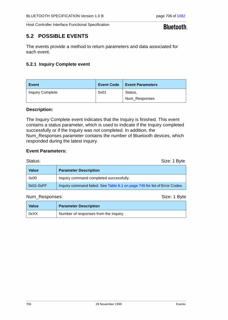
BLUETOOTH SPECIFICATION Version 1.0 B page 706 of 1082
Host Controller Interface Functional Specification
5.2 POSSIBLE EVENTS
The events provide a method to return parameters and data associated for each event.
5.2.1 Inquiry Complete event
Description:
The Inquiry Complete event indicates that the Inquiry is finished. This event contains a status parameter, which is used to indicate if the Inquiry completed successfully or if the Inquiry was not completed. In addition, the Num_Responses parameter contains the number of Bluetooth devices, which responded during the latest inquiry.
Event Parameters:
Status: Size: 1 Byte
Num_Responses: Size: 1 Byte
Event Event Code Event Parameters
Inquiry Complete 0x01 Status,
Num_Responses
Value Parameter Description
0x00 Inquiry command completed successfully.
0x01-0xFF Inquiry command failed. See Table 6.1 on page 745 for list of Error Codes.
Value Parameter Description
0xXX Number of responses from the Inquiry.
706 29 November 1999 Events

BLUETOOTH SPECIFICATION Version 1.0 B page 707 of 1082
Host Controller Interface Functional Specification
5.2.2 Inquiry Result event
Description:
The Inquiry Result event indicates that a Bluetooth device or multiple Bluetooth devices have responded so far during the current Inquiry process. This event will be sent from the Host Controller to the Host as soon as an Inquiry Response from a remote device is received if the remote device supports only mandatory paging scheme. The Host Controller may queue these Inquiry Responses and send multiple Bluetooth devices information in one Inquiry Result event. The event can be used to return one or more Inquiry responses in one event. This event contains the BD_ADDR, Page_Scan_Repetition_Mode, Page_Scan_Period_Mode, Page_Scan_Mode, Clock_Offset, and the Class of Device for each Bluetooth device that responded to the latest inquiry.
Event Parameters:
Num_Responses: Size: 1 Byte
BD_ADDR[i]: Size: 6 Bytes * Num_Responses
Event Event Code Event Parameters
Inquiry Result 0x02 Num_Responses,
BD_ADDR[i],
Page_Scan_Repetition_Mode[i],
Page_Scan_Period_Mode[i],
Page_Scan_Mode[i],
Class_of_Device[i]
Clock_Offset[i]
Value Parameter Description
0xXX Number of responses from the Inquiry.
Value Parameter Description
0xXXXXXXXXXXXX
BD_ADDR for each device which responded.
Events 29 November 1999 707

BLUETOOTH SPECIFICATION Version 1.0 B page 708 of 1082
Host Controller Interface Functional Specification
Page_Scan_Repetition_Mode[i]: Size: 1 Byte* Num_Responses
Page_Scan_Period_Mode[i]: Size: 1 Byte* Num_Responses
Page_Scan_Mode[i]: Size: 1 Byte* Num_Responses
Class_of_Device[i]: Size: 3 Bytes * Num_Responses
Clock_Offset[i]: Size: 2 Bytes * Num_Responses
Value Parameter Description
0x00 R0
0x01 R1
0x02 R2
0x03 – 0xFF Reserved
Value Parameter Description
0x00 P0
0x01 P1
0x02 P2
0x03 – 0xFF Reserved
Value Parameter Description
0x00 Mandatory Page Scan Mode
0x01 Optional Page Scan Mode I
0x02 Optional Page Scan Mode II
0x03 Optional Page Scan Mode III
0x04 – 0xFF Reserved
Value Parameter Description
0xXXXXXX Class of Device for the device
Bit format Parameter Description
Bit 14.0 Bit 16.2 of CLKslave-CLKmaster.
Bit 15 Reserved
708 29 November 1999 Events

BLUETOOTH SPECIFICATION Version 1.0 B page 709 of 1082
Host Controller Interface Functional Specification
5.2.3 Connection Complete event
Description:
The Connection Complete event indicates to both of the Hosts forming the con-nection that a new connection has been established. This event also indicates to the Host, which issued the Create Connection, Add_SCO_Connection, or Accept_Connection_Request or Reject_Connection_Request command and then received a Command Status event, if the issued command failed or was successful.
Event Parameters:
Status: Size: 1 Byte
Connection_Handle: Size: 2 Bytes (12 Bits meaningful)
BD_ADDR: Size: 6 Bytes
Event Event Code Event Parameters
Connection Complete 0x03 Status,
Connection_Handle,
BD_ADDR,
Link_Type,
Encryption_Mode
Value Parameter Description
0x00 Connection successfully completed.
0x01-0xFF Connection failed to Complete. See Table 6.1 on page 745 for list of Error Codes.
Value Parameter Description
0xXXXX Connection Handle to be used to identify a connection between to Blue-tooth devices. The Connection Handle is used as an identifier for transmit-ting and receiving voice or data.
Range: 0x0000-0x0EFF (0x0F00 - 0x0FFF Reserved for future use)
Value Parameter Description
0xXXXXXXXXXXXX BD_ADDR of the other connected Device forming the connection.
Events 29 November 1999 709

BLUETOOTH SPECIFICATION Version 1.0 B page 710 of 1082
Host Controller Interface Functional Specification
Link_Type: Size: 1 Byte
Encryption_Mode: Size: 1 Byte
Value Parameter Description
0x00 SCO connection (Voice Channels).
0x01 ACL connection (Data Channels).
0x02-0xFF Reserved for Future Use.
Value Parameter Description
0x00 Encryption disabled.
0x01 Encryption only for point-to-point packets.
0x02 Encryption for both point-to-point and broadcast packets.
0x03-0xFF Reserved.
710 29 November 1999 Events
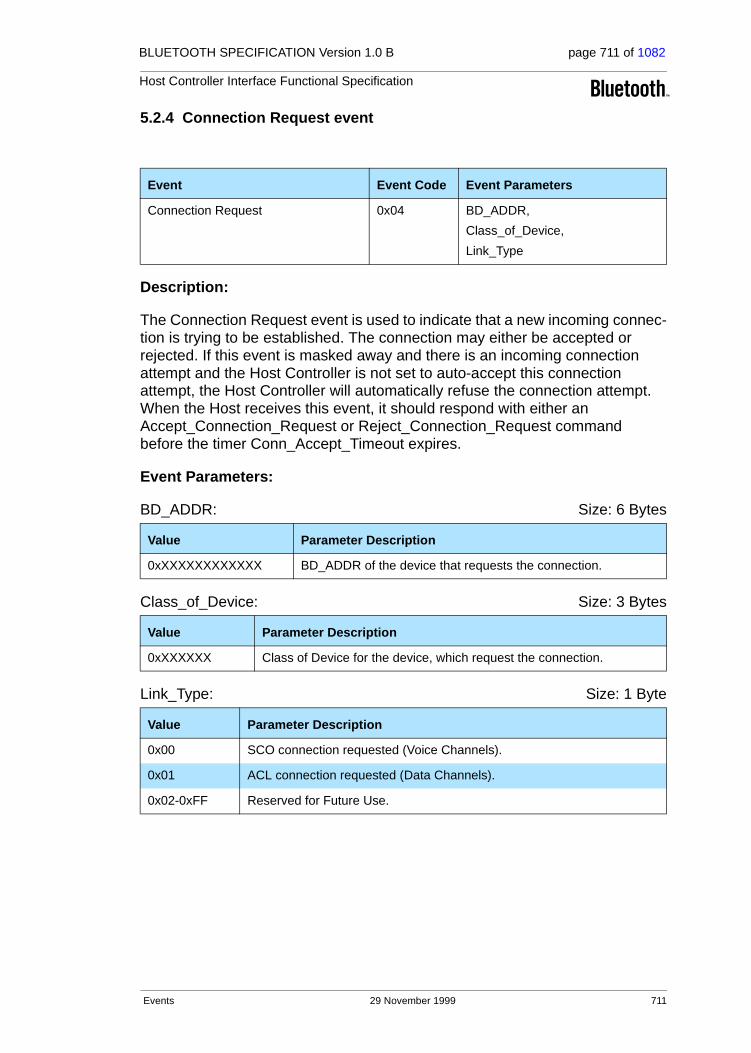
BLUETOOTH SPECIFICATION Version 1.0 B page 711 of 1082
Host Controller Interface Functional Specification
5.2.4 Connection Request event
Description:
The Connection Request event is used to indicate that a new incoming connec-tion is trying to be established. The connection may either be accepted or rejected. If this event is masked away and there is an incoming connection attempt and the Host Controller is not set to auto-accept this connection attempt, the Host Controller will automatically refuse the connection attempt. When the Host receives this event, it should respond with either an Accept_Connection_Request or Reject_Connection_Request command before the timer Conn_Accept_Timeout expires.
Event Parameters:
BD_ADDR: Size: 6 Bytes
Class_of_Device: Size: 3 Bytes
Link_Type: Size: 1 Byte
Event Event Code Event Parameters
Connection Request 0x04 BD_ADDR,
Class_of_Device,
Link_Type
Value Parameter Description
0xXXXXXXXXXXXX BD_ADDR of the device that requests the connection.
Value Parameter Description
0xXXXXXX Class of Device for the device, which request the connection.
Value Parameter Description
0x00 SCO connection requested (Voice Channels).
0x01 ACL connection requested (Data Channels).
0x02-0xFF Reserved for Future Use.
Events 29 November 1999 711

BLUETOOTH SPECIFICATION Version 1.0 B page 712 of 1082
Host Controller Interface Functional Specification
5.2.5 Disconnection Complete event
Description:
The Disconnection Complete event occurs when a connection is terminated. The status parameter indicates if the disconnection was successful or not. The reason parameter indicates the reason for the disconnection if the disconnec-tion was successful. If the disconnection was not successful, the value of the reason parameter can be ignored by the Host. For example, this can be the case if the Host has issued the Disconnect command and there was a parame-ter error, or the command was not presently allowed, or a connection handle that didn’t correspond to a connection was given. Note: When a physical link fails, one Disconnection Complete event will be returned for each logical channel on the physical link with the corresponding Connection handle as a parameter.
Event Parameters:
Status: Size: 1 Byte
Connection_Handle: Size: 2 Bytes (12 Bits meaningful)
Reason: Size: 1 Byte
Event Event Code Event Parameters
Disconnection Complete 0x05 Status,
Connection_Handle, Reason
Value Parameter Description
0x00 Disconnection has occurred.
0x01-0xFF Disconnection failed to complete. See Table 6.1 on page 745 for list of Error Codes.
Value Parameter Description
0xXXXX Connection Handle which was disconnected.
Range: 0x0000-0x0EFF (0x0F00 - 0x0FFF Reserved for future use)
Value Parameter Description
0x08, 0x13-0x16, 0x1A
Connection Timeout (0x08), Other End Terminated Connection error codes (0x13-0x15), Connection Terminated by Local Host (0x16), and Unsupported Remote Feature error code (0x1A). See Table 6.1 on page 745 for list of Error Codes.
712 29 November 1999 Events

BLUETOOTH SPECIFICATION Version 1.0 B page 713 of 1082
Host Controller Interface Functional Specification
5.2.6 Authentication Complete event
Description:
The Authentication Complete event occurs when authentication has been com-pleted for the specified connection. The Connection_Handle must be a Connection_Handle for an ACL connection.
Event Parameters:
Status: Size: 1 Byte
Connection_Handle: Size: 2 Bytes (12 Bits meaningful)
Event Event Code Event Parameters
Authentication Complete 0x06 Status, Connection_Handle
Value Parameter Description
0x00 Authentication Request successfully completed.
0x01-0xFF Authentication Request failed to complete. See Table 6.1 on page 745 for list of Error Codes.
Value Parameter Description
0xXXXX Connection Handle for which Authentication has been performed.
Range: 0x0000-0x0EFF (0x0F00 - 0x0FFF Reserved for future use)
Events 29 November 1999 713
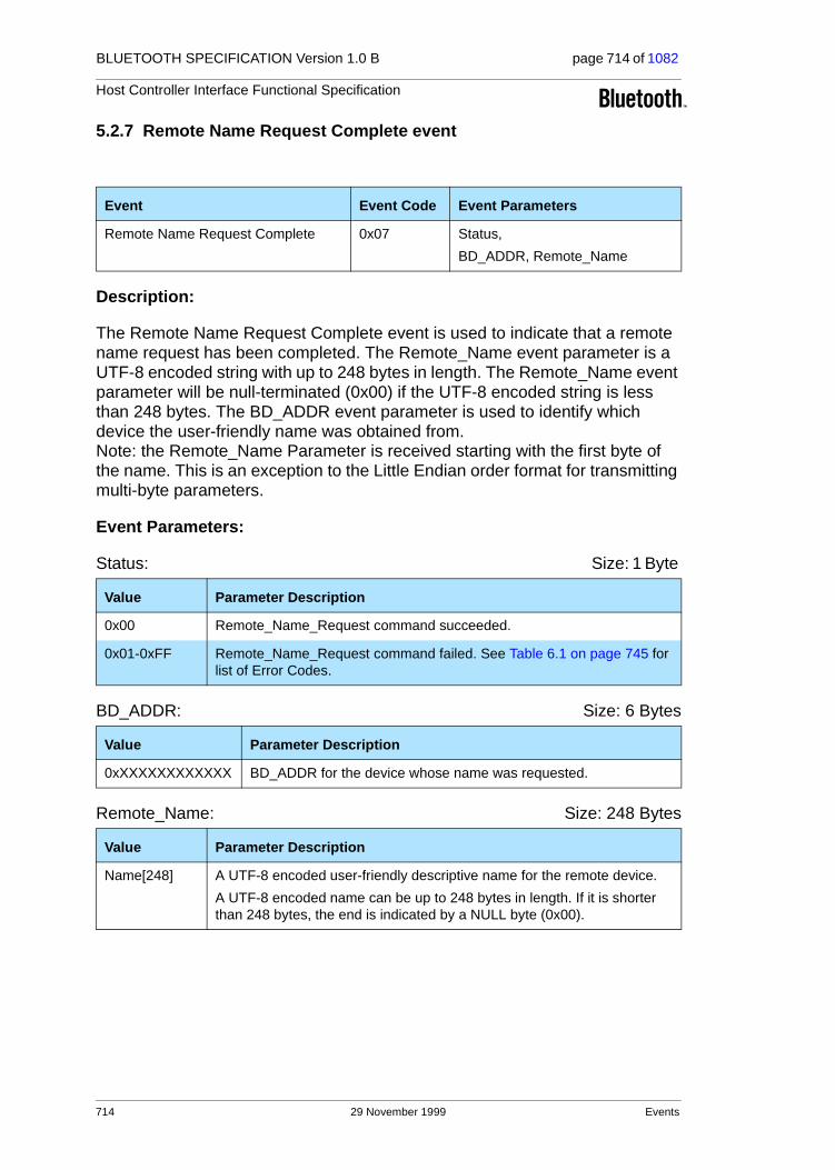
BLUETOOTH SPECIFICATION Version 1.0 B page 714 of 1082
Host Controller Interface Functional Specification
5.2.7 Remote Name Request Complete event
Description:
The Remote Name Request Complete event is used to indicate that a remote name request has been completed. The Remote_Name event parameter is a UTF-8 encoded string with up to 248 bytes in length. The Remote_Name event parameter will be null-terminated (0x00) if the UTF-8 encoded string is less than 248 bytes. The BD_ADDR event parameter is used to identify which device the user-friendly name was obtained from. Note: the Remote_Name Parameter is received starting with the first byte of the name. This is an exception to the Little Endian order format for transmitting multi-byte parameters.
Event Parameters:
Status: Size: 1 Byte
BD_ADDR: Size: 6 Bytes
Remote_Name: Size: 248 Bytes
Event Event Code Event Parameters
Remote Name Request Complete 0x07 Status,
BD_ADDR, Remote_Name
Value Parameter Description
0x00 Remote_Name_Request command succeeded.
0x01-0xFF Remote_Name_Request command failed. See Table 6.1 on page 745 for list of Error Codes.
Value Parameter Description
0xXXXXXXXXXXXX BD_ADDR for the device whose name was requested.
Value Parameter Description
Name[248] A UTF-8 encoded user-friendly descriptive name for the remote device.
A UTF-8 encoded name can be up to 248 bytes in length. If it is shorter than 248 bytes, the end is indicated by a NULL byte (0x00).
714 29 November 1999 Events

BLUETOOTH SPECIFICATION Version 1.0 B page 715 of 1082
Host Controller Interface Functional Specification
5.2.8 Encryption Change event
Description:
The Encryption Change event is used to indicate that the change in the encryp-tion has been completed for the Connection Handle specified by the Connection_Handle event parameter. The Connection_Handle will be a Connection_Handle for an ACL connection. The Encryption_Enable event parameter specifies the new Encryption Enable for the Connection Handle specified by the Connection_Handle event parameter. This event will occur on both devices to notify both Hosts when Encryption has changed for the speci-fied Connection Handle between two devices.
Event Parameters:
Status: Size: 1 Byte
Connection_Handle: Size: 2 Bytes (12 Bits meaningful)
Encryption_Enable: Size: 1 Byte
Event Event Code Event Parameters
Encryption Change 0x08 Status,
Connection_Handle,
Encryption_Enable
Value Parameter Description
0x00 Encryption Change has occurred.
0x01-0xFF Encryption Change failed. See Table 6.1 on page 745 for list of Error Codes.
Value Parameter Description
0xXXXX Connection Handle for which the link layer encryption has been enabled/disabled for all Connection Handles with the same Bluetooth device end-point as the specified Connection Handle.
Range: 0x0000-0x0EFF (0x0F00 - 0x0FFF Reserved for future use)
Value Parameter Description
0x00 Link Level Encryption is OFF.
0x01 Link Level Encryption is ON.
Events 29 November 1999 715

BLUETOOTH SPECIFICATION Version 1.0 B page 716 of 1082
Host Controller Interface Functional Specification
5.2.9 Change Connection Link Key Complete event
Description:
The Change Connection Link Key Complete event is used to indicate that the change in the Link Key for the Connection Handle specified by the Connection_Handle event parameter has been completed. The Connection_Handle will be a Connection_Handle for an ACL connection. The Change Connection Link Key Complete event is sent only to the Host which issued the Change_Connection_Link_Key command.
Event Parameters:
Status: Size: 1 Byte
Connection_Handle: Size: 2 Bytes (12 Bits meaningful)
Event Event Code Event Parameters
Change Connection Link Key Complete 0x09 Status, Connection_Handle
Value Parameter Description
0x00 Change_Connection_Link_Key command succeeded.
0x01-0xFF Change_Connection_Link_Key command failed. See Table 6.1 on page 745 for list of Error Codes.
Value Parameter Description
0xXXXX Connection Handle which the Link Key has been change for all Connec-tion Handles with the same Bluetooth device end point as the specified Connection Handle.
Range: 0x0000-0x0EFF (0x0F00 - 0x0FFF Reserved for future use)
716 29 November 1999 Events

BLUETOOTH SPECIFICATION Version 1.0 B page 717 of 1082
Host Controller Interface Functional Specification
5.2.10 Master Link Key Complete event
Description:
The Master Link Key Complete event is used to indicate that the Link Key man-aged by the master of the piconet has been changed. The Connection_Handle will be a Connection_Handle for an ACL connection. The link key used for the connection will be the temporary link key of the master device or the semi-permanent link key indicated by the Key_Flag. The Key_Flag event parameter is used to indicate which Link Key (temporary link key of the Master, or the semi-permanent link keys) is now being used in the piconet. Note: for a master, the change from a semi-permanent Link Key to temporary Link Key will affect all Connection Handles related to the piconet. For a slave, this change affects only this particular connection handle. A temporary link key must be used when both broadcast and point-to-point traffic shall be encrypted.
Event Parameters:
Status: Size: 1 Byte
Connection_Handle: Size: 2 Bytes (12 Bits meaningful)
Key_Flag: Size: 1 Byte
Event Event Code Event Parameters
Master Link Key Complete 0x0A Status,
Connection_Handle, Key_Flag
Value Parameter Description
0x00 Master_Link_Key command succeeded.
0x01-0xFF Master_Link_Key command failed. See Table 6.1 on page 745 for list of Error Codes.
Value Parameter Description
0xXXXX Connection Handle for which the Link Key has been changed for all devices in the same piconet.
Range: 0x0000-0x0EFF (0x0F00 - 0x0FFF Reserved for future use)
Value Parameter Description
0x00 Using Semi-permanent Link Key.
0x01 Using Temporary Link Key.
Events 29 November 1999 717

BLUETOOTH SPECIFICATION Version 1.0 B page 718 of 1082
Host Controller Interface Functional Specification
5.2.11 Read Remote Supported Features Complete event
Description:
The Read Remote Supported Features Complete event is used to indicate the completion of the process of the Link Manager obtaining the supported features of the remote Bluetooth device specified by the Connection_Handle event parameter. The Connection_Handle will be a Connection_Handle for an ACL connection. The event parameters include a list of LMP features. For details see “Link Manager Protocol” on page 185.
Event Parameters:
Status: Size: 1 Byte
Connection_Handle: Size: 2 Bytes (12 Bits meaningful)
LMP_Features: Size: 8 Bytes
Event Event Code Event Parameters
Read Remote Supported
Features Complete
0x0B Status,
Connection_Handle, LMP_Features
Value Parameter Description
0x00 Read_Remote_Supported_Features command succeeded.
0x01-0xFF Read_Remote_Supported_Features command failed. See Table 6.1 on page 745 for list of Error Codes.
Value Parameter Description
0xXXXX Connection Handle which is used for the Read_Remote_Supported_Features command.
Range: 0x0000-0x0EFF (0x0F00 - 0x0FFF Reserved for future use)
Value Parameter Description
0xXXXXXXXXXXXXXXXX
Bit Mask List of LMP features. See “Link Manager Protocol” on page 185.
718 29 November 1999 Events

BLUETOOTH SPECIFICATION Version 1.0 B page 719 of 1082
Host Controller Interface Functional Specification
5.2.12 Read Remote Version Information Complete event
Description:
The Read Remote Version Information Complete event is used to indicate the completion of the process of the Link Manager obtaining the version informa-tion of the remote Bluetooth device specified by the Connection_Handle event parameter. The Connection_Handle will be a Connection_Handle for an ACL connection. The LMP_Version event parameter defines the major hardware version of the Bluetooth hardware. This event parameter only changes when new versions of the Bluetooth hardware are produced for new Bluetooth SIG specifications; it is controlled by the SIG. The Manufacturer_Name event parameter indicates the manufacturer of the remote Bluetooth module. The LMP_Subversion event parameter should be controlled by the manufacturer and should be changed as needed. The LMP_Subversion event parameter defines the various revisions that each version of the Bluetooth hardware will go through as design processes change and errors are fixed. This allows the soft-ware to determine what Bluetooth hardware is being used and, if necessary, to work around various bugs in the hardware.
Event Parameters:
Status: Size: 1 Byte
Connection_Handle: Size: 2 Bytes (12 Bits meaningful)
Event Event Code Event Parameters
Read Remote Version Information Complete
0x0C Status,
Connection_Handle,
LMP_Version,
Manufacturer_Name,
LMP_Subversion
Value Parameter Description
0x00 Read_Remote_Version_Information command succeeded.
0x01-0xFF Read_Remote_Version_Information command failed. See Table 6.1 on page 745 for list of Error Codes.
Value Parameter Description
0xXXXX Connection Handle which is used for the Read_Remote_Version_Information command.
Range: 0x0000-0x0EFF (0x0F00 - 0x0FFF Reserved for future use)
Events 29 November 1999 719

BLUETOOTH SPECIFICATION Version 1.0 B page 720 of 1082
Host Controller Interface Functional Specification
LMP_Version: Size: 1 Byte
Manufacturer_Name: Size: 2 Bytes
LMP_Subversion: Size: 2 Bytes
Value Parameter Description
0xXX Version of the Current LMP in the remote Bluetooth Hardware, see Table 5.2 on page 231 in the Link Manager Protocol for assigned val-ues (VersNr).
Value Parameter Description
0xXXXX Manufacturer Name of the remote Bluetooth Hardware, see Table 5.2 on page 231 in the Link Manager Protocol for assigned val-ues (CompId).
Value Parameter Description
0xXXXX Subversion of the Current LMP in the remote Bluetooth Hardware, see Table 5.2 on page 231 in the Link Manager Protocol for assigned values (SubVersNr).
720 29 November 1999 Events

BLUETOOTH SPECIFICATION Version 1.0 B page 721 of 1082
Host Controller Interface Functional Specification
5.2.13 QoS Setup Complete event
Description:
The QoS Setup Complete event is used to indicate the completion of the process of the Link Manager setting up QoS with the remote Bluetooth device specified by the Connection_Handle event parameter. The Connection_Handle will be a Connection_Handle for an ACL connection. For more detail see “Logi-cal Link Control and Adaptation Protocol Specification” on page 245.
Event Parameters:
Status: Size: 1 Byte
Connection_Handle: Size: 2 Bytes (12 Bits meaningful)
Flags: Size: 1 Byte
Event Event Code Event Parameters
QoS Setup Complete 0x0D Status,
Connection_Handle,
Flags,
Service_Type,
Token_Rate,
Peak_Bandwidth,
Latency,
Delay_Variation
Value Parameter Description
0x00 QoS_Setup command succeeded.
0x01-0xFF QoS_Setup command failed. See Table 6.1 on page 745 for list of Error Codes.
Value Parameter Description
0xXXXX Connection Handle which is used for the QoS_Setup command.
Range: 0x0000-0x0EFF (0x0F00 - 0x0FFF Reserved for future use)
Value Parameter Description
0x00 – 0xFF Reserved for Future Use.
Events 29 November 1999 721

BLUETOOTH SPECIFICATION Version 1.0 B page 722 of 1082
Host Controller Interface Functional Specification
Service_Type: Size: 1 Byte
Token_Rate: Size: 4 Bytes
Peak_Bandwidth: Size: 4 Bytes
Latency: Size: 4 Bytes
Delay_Variation: Size: 4 Bytes
Value Parameter Description
0x00 No Traffic Available.
0x01 Best Effort Available.
0x02 Guaranteed Available.
0x03-0xFF Reserved for Future Use.
Value Parameter Description
0xXXXXXXXX Available Token Rate, in bytes per second.
Value Parameter Description
0xXXXXXXXX Available Peak Bandwidth, in bytes per second.
Value Parameter Description
0xXXXXXXXX Available Latency, in microseconds.
Value Parameter Description
0xXXXXXXXX Available Delay Variation, in microseconds.
722 29 November 1999 Events

BLUETOOTH SPECIFICATION Version 1.0 B page 723 of 1082
Host Controller Interface Functional Specification
5.2.14 Command Complete event
Description:
The Command Complete event is used by the Host Controller for most com-mands to transmit return status of a command and the other event parameters that are specified for the issued HCI command.
The Num_HCI_Command_Packets event parameter allows the Host Controller to indicate the number of HCI command packets the Host can send to the Host Controller. If the Host Controller requires the Host to stop sending commands, the Num_HCI_Command_Packets event parameter will be set to zero. To indi-cate to the Host that the Host Controller is ready to receive HCI command packets, the Host Controller generates a Command Complete event with the Command_Opcode 0x0000, and the Num_HCI_Command_Packets event parameter is set to 1 or more. Command_Opcode, 0x0000 is a NOP (No OPer-ation), and can be used to change the number of outstanding HCI command packets that the Host can send before waiting. See each command for the parameters that are returned by this event.
Event Parameters:
Num_HCI_Command_Packets: Size: 1 Byte
Command_Opcode: Size: 2 Bytes
Return_Parameter(s): Size: Depends on Command
Event Event Code Event Parameters
Command Complete 0x0E Num_HCI_Command_Packets,
Command_Opcode, Return_Parameters
Value Parameter Description
N = 0xXX The Number of HCI command packets which are allowed to be sent to the Host Controller from the Host.
Range for N: 0 – 255
Value Parameter Description
0xXXXX Opcode of the command which caused this event.
Value Parameter Description
0xXX This is the return parameter(s) for the command specified in the Command_Opcode event parameter. See each command’s definition for the list of return parameters associated with that command.
Events 29 November 1999 723

BLUETOOTH SPECIFICATION Version 1.0 B page 724 of 1082
Host Controller Interface Functional Specification
5.2.15 Command Status event
Description:
The Command Status event is used to indicate that the command described by the Command_Opcode parameter has been received, and that the Host Control-ler is currently performing the task for this command. This event is needed to provide mechanisms for asynchronous operation, which makes it possible to pre-vent the Host from waiting for a command to finish. If the command can not begin to execute (a parameter error may have occurred, or the command may currently not be allowed), the Status event parameter will contain the corre-sponding error code, and no complete event will follow since the command was not started. The Num_HCI_Command_Packets event parameter allows the Host Controller to indicate the number of HCI command packets the Host can send to the Host Controller. If the Host Controller requires the Host to stop sending com-mands, the Num_HCI_Command_Packets event parameter will be set to zero. To indicate to the Host that the Host Controller is ready to receive HCI command packets, the Host Controller generates a Command Status event with Status 0x00 and Command_Opcode 0x0000, and the Num_HCI_Command_Packets event parameter is set to 1 or more. Command_Opcode, 0x0000 is a NOP (No OPeration) and can be used to change the number of outstanding HCI command packets that the Host can send before waiting.
Event Parameters:
Status: Size: 1 Byte
Num_HCI_Command_Packets: Size: 1 Byte
Command_Opcode: Size: 2 Bytes
Event Event Code Event Parameters
Command Status 0x0F Status,
Num_HCI_Command_Packets,
Command_Opcode
Value Parameter Description
0x00 Command currently in pending.
0x01-0xFF Command failed. See Table 6.1 on page 745 for list of Error Codes.
Value Parameter Description
N = 0xXX The Number of HCI command packets which are allowed to be sent to the Host Controller from the Host.
Range for N: 0 – 255
Value Parameter Description
0xXXXX Opcode of the command which caused this event and is pending completion.
724 29 November 1999 Events

BLUETOOTH SPECIFICATION Version 1.0 B page 725 of 1082
Host Controller Interface Functional Specification
5.2.16 Hardware Error event
Description:
The Hardware Error event is used to indicate some type of hardware failure for the Bluetooth device. This event is used to notify the Host that a hardware failure has occurred in the Bluetooth module.
Event Parameters:
Hardware_Code: Size: 1 Byte
Event Event Code Event Parameters
Hardware Error 0x10 Hardware_Code
Value Parameter Description
0x00 These Hardware_Codes will be implementation-specific, and will be assigned to indicate various hardware problems.
Events 29 November 1999 725
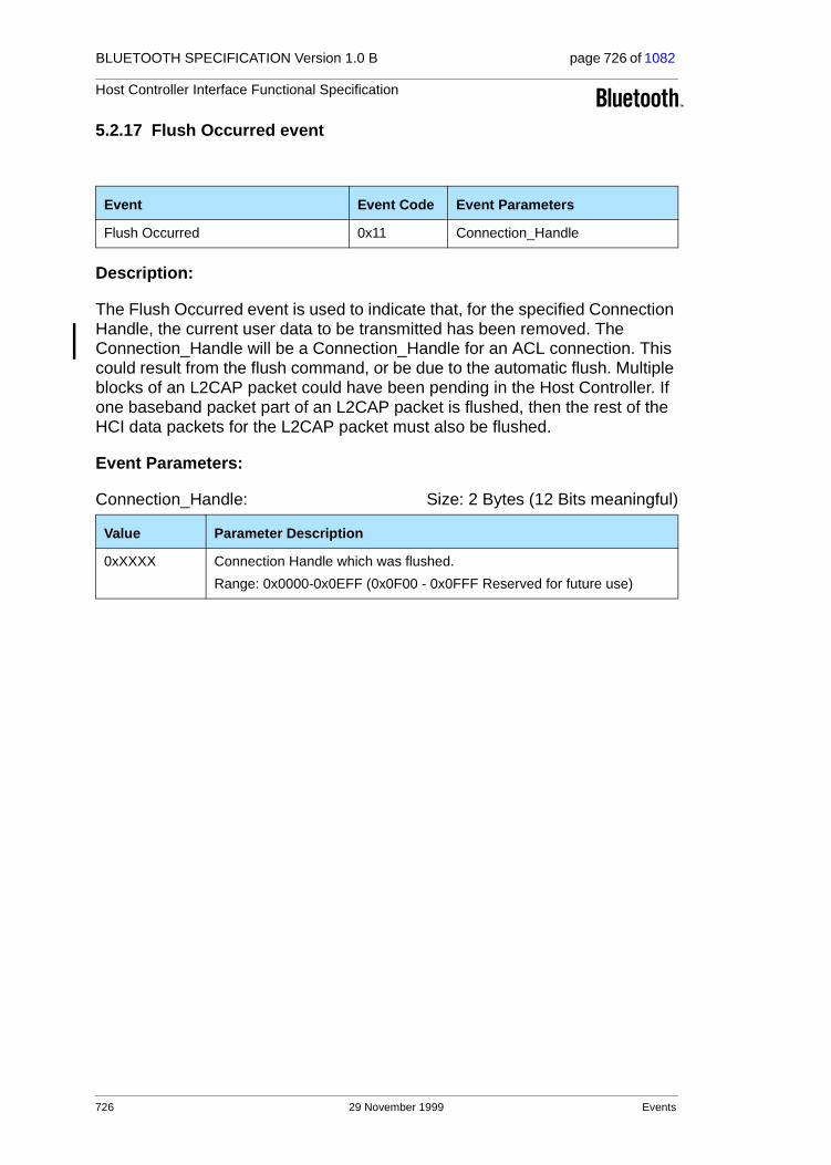
BLUETOOTH SPECIFICATION Version 1.0 B page 726 of 1082
Host Controller Interface Functional Specification
5.2.17 Flush Occurred event
Description:
The Flush Occurred event is used to indicate that, for the specified Connection Handle, the current user data to be transmitted has been removed. The Connection_Handle will be a Connection_Handle for an ACL connection. This could result from the flush command, or be due to the automatic flush. Multiple blocks of an L2CAP packet could have been pending in the Host Controller. If one baseband packet part of an L2CAP packet is flushed, then the rest of the HCI data packets for the L2CAP packet must also be flushed.
Event Parameters:
Connection_Handle: Size: 2 Bytes (12 Bits meaningful)
Event Event Code Event Parameters
Flush Occurred 0x11 Connection_Handle
Value Parameter Description
0xXXXX Connection Handle which was flushed.
Range: 0x0000-0x0EFF (0x0F00 - 0x0FFF Reserved for future use)
726 29 November 1999 Events

BLUETOOTH SPECIFICATION Version 1.0 B page 727 of 1082
Host Controller Interface Functional Specification
5.2.18 Role Change event
Description:
The Role Change event is used to indicate that the current Bluetooth role related to the particular connection has changed. This event only occurs when both the remote and local Bluetooth devices have completed their role change for the Bluetooth device associated with the BD_ADDR event parameter. This event allows both affected Hosts to be notified when the Role has been changed.
Event Parameters:
Status: Size: 1 Byte
BD_ADDR: Size: 6 Bytes
New_Role: Size: 1 Byte
Event Event Code Event Parameters
Role Change 0x12 Status,
BD_ADDR, New_Role
Value Parameter Description
0x00 Role change has occurred.
0x01-0xFF Role change failed. See Table 6.1 on page 745 for list of Error Codes.
Value Parameter Description
0xXXXXXXXXXXXX BD_ADDR of the Device for which a role change has completed.
Value Parameter Description
0x00 Currently the Master for specified BD_ADDR.
0x01 Currently the Slave for specified BD_ADDR.
Events 29 November 1999 727

BLUETOOTH SPECIFICATION Version 1.0 B page 728 of 1082
Host Controller Interface Functional Specification
5.2.19 Number Of Completed Packets event
Description:
The Number Of Completed Packets event is used by the Host Controller to indicate to the Host how many HCI Data Packets have been completed (transmitted or flushed) for each Connection Handle since the previous Number Of Completed Packets event was sent to the Host. This means that the corresponding buffer space has been freed in the Host Controller. Based on this information, and the HC_Total_Num_ACL_Data_Packets and HC_Total_Num_SCO_Data_Packets return parameter of the Read_Buffer_Size command, the Host can determine for which Connection Handles the following HCI Data Packets should be sent to the Host Controller.The Number Of Completed Packets event must not be sent before the corresponding Connec-tion Complete event. While the Host Controller has HCI data packets in its buffer, it must keep sending the Number Of Completed Packets event to the Host at least periodically, until it finally reports that all the pending ACL Data Packets have been transmitted or flushed. The rate with which this event is sent is manufacturer specific.Note that Number Of Completed Packets events will not report on SCO con-nection handles if SCO Flow Control is disabled. (See Read/Write_SCO_Flow_Control_Enable on page 658 and page 659.)
Event Parameters:
Number_of_Handles: Size: 1 Byte
Connection_Handle[i]:Size: Number_of_Handles * 2 Bytes(12 Bits meaningful)
Event Event Code Event Parameters
Number Of Completed Packets 0x13 Number_of_Handles,
Connection_Handle[i],
HC_Num_Of_Completed_Packets[i]
Value Parameter Description
0xXX The number of Connection Handles and Num_HCI_Data_Packets parameters pairs contained in this event.
Range: 0-255
Value Parameter Description
0xXXXX Connection Handle.
Range: 0x0000-0x0EFF (0x0F00 - 0x0FFF Reserved for future use)
728 29 November 1999 Events

BLUETOOTH SPECIFICATION Version 1.0 B page 729 of 1082
Host Controller Interface Functional Specification
HC_Num_Of_Completed_Packets [i]: Size: Number_of_Handles * 2 Bytes
Value Parameter Description
N = 0xXXXX The number of HCI Data Packets that have been completed (transmitted or flushed) for the associated Connection Handle since the previous time the event was returned.
Range for N: 0x0000-0xFFFF
Events 29 November 1999 729
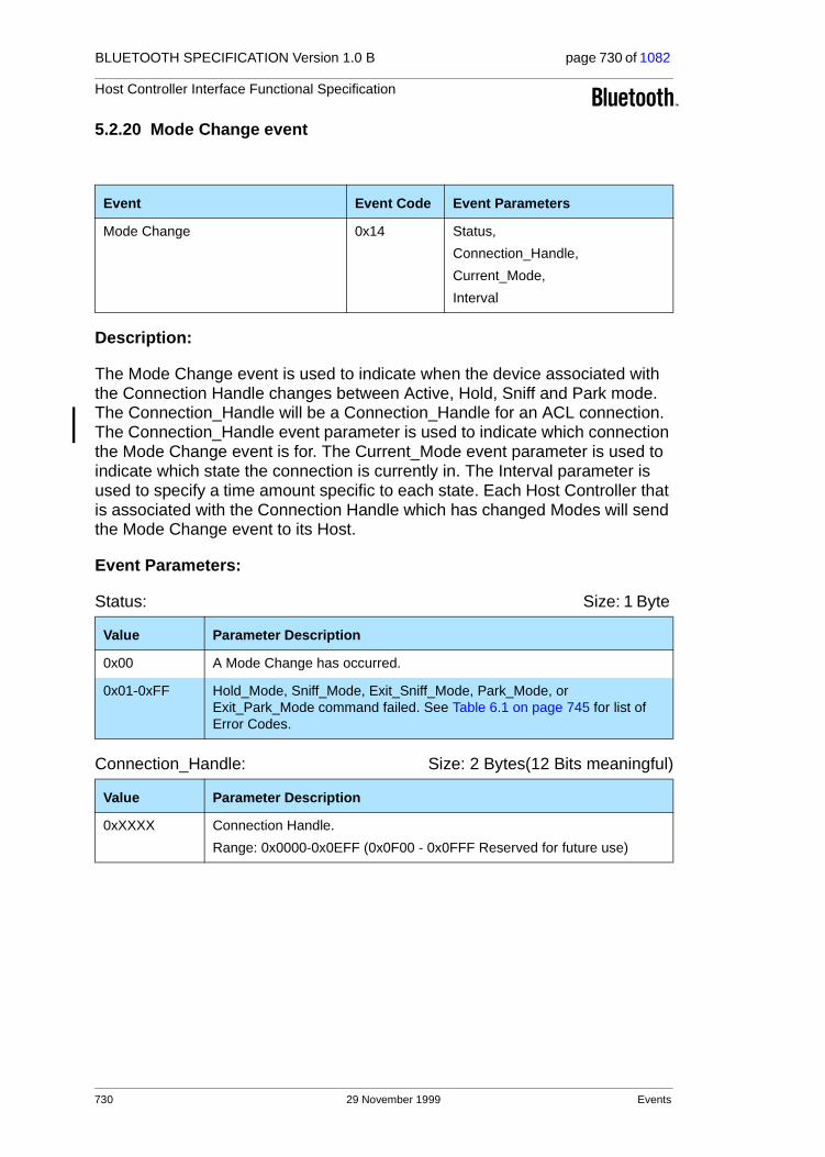
BLUETOOTH SPECIFICATION Version 1.0 B page 730 of 1082
Host Controller Interface Functional Specification
5.2.20 Mode Change event
Description:
The Mode Change event is used to indicate when the device associated with the Connection Handle changes between Active, Hold, Sniff and Park mode. The Connection_Handle will be a Connection_Handle for an ACL connection. The Connection_Handle event parameter is used to indicate which connection the Mode Change event is for. The Current_Mode event parameter is used to indicate which state the connection is currently in. The Interval parameter is used to specify a time amount specific to each state. Each Host Controller that is associated with the Connection Handle which has changed Modes will send the Mode Change event to its Host.
Event Parameters:
Status: Size: 1 Byte
Connection_Handle: Size: 2 Bytes(12 Bits meaningful)
Event Event Code Event Parameters
Mode Change 0x14 Status,
Connection_Handle,
Current_Mode,
Interval
Value Parameter Description
0x00 A Mode Change has occurred.
0x01-0xFF Hold_Mode, Sniff_Mode, Exit_Sniff_Mode, Park_Mode, or Exit_Park_Mode command failed. See Table 6.1 on page 745 for list of Error Codes.
Value Parameter Description
0xXXXX Connection Handle.
Range: 0x0000-0x0EFF (0x0F00 - 0x0FFF Reserved for future use)
730 29 November 1999 Events

BLUETOOTH SPECIFICATION Version 1.0 B page 731 of 1082
Host Controller Interface Functional Specification
Current_Mode: Size: 1 Byte
Interval: Size: 2 Bytes
Value Parameter Description
0x00 Active Mode.
0x01 Hold Mode.
0x02 Sniff Mode.
0x03 Park Mode.
0x04-0xFF Reserved for future use.
Value Parameter Description
N = 0xXXXX Hold:
Number of Baseband slots to wait in Hold Mode.
Hold Interval = N * 0.625 msec (1 Baseband slot)
Range for N: 0x0000-0xFFFF
Time Range: 0-40.9 sec
Sniff:
Number of Baseband slots between sniff intervals.
Time between sniff intervals = 0.625 msec (1 Baseband slot)
Range for N: 0x0000-0xFFFF
Time Range: 0-40.9 sec
Park:
Number of Baseband slots between consecutive beacons.
Interval Length = N * 0.625 msec (1 Baseband slot)
Range for N: 0x0000-0xFFFF
Time Range: 0-40.9 Seconds
Events 29 November 1999 731

BLUETOOTH SPECIFICATION Version 1.0 B page 732 of 1082
Host Controller Interface Functional Specification
5.2.21 Return Link Keys event
Description:
The Return Link Keys event is used by the Host Controller to send the Host one or more stored Link Keys. Zero or more instances of this event will occur after the Read_Stored_Link_Key command. When there are no link keys stored, no Return Link Keys events will be returned. When there are link keys stored, the number of link keys returned in each Return Link Keys event is implementation specific.
Event Parameters:
Num_Keys: Size: 1 Byte
BD_ADDR [i]: Size: 6 Bytes * Num_Keys
Link_Key[i]: Size:16 Bytes * Num_Keys
Event Event Code Event Parameters
Return Link Keys 0x15 Num_Keys,
BD_ADDR [i], Link_Key[i]
Value Parameter Description
0xXX Number of Link Keys contained in this event.
Range: 0x01 – 0xFF
Value Parameter Description
0xXXXXXXXXXXXX BD_ADDR for the associated Link Key.
Value Parameter Description
0xXXXXXXXXXXXXXXXXXXXXXXXXXXXXXXXX
Link Key for the associated BD_ADDR.
732 29 November 1999 Events

BLUETOOTH SPECIFICATION Version 1.0 B page 733 of 1082
Host Controller Interface Functional Specification
5.2.22 PIN Code Request event
Description:
The PIN Code Request event is used to indicate that a PIN code is required to create a new link key. The Host must respond using either the PIN Code Request Reply or the PIN Code Request Negative Reply command, depending on whether the Host can provide the Host Controller with a PIN code or not.Note: If the PIN Code Request event is masked away, then the Host Controller will assume that the Host has no PIN Code.
When the Host Controller generates a PIN Code Request event in order for the local Link Manager to respond to the request from the remote Link Manager (as a result of a Create_Connection or Authentication_Requested command from the remote Host), the local Host must respond with either a PIN_Code_Request_Reply or PIN_Code_Request_Negative_Reply com-mand before the remote Link Manager detects LMP response timeout. (See “Link Manager Protocol” on page 185.)
Event Parameters:
BD_ADDR: Size: 6 Bytes
Event Event Code Event Parameters
PIN Code Request 0x16 BD_ADDR
Value Parameter Description
0xXXXXXXXXXXXX BD_ADDR of the Device which a new link key is being created for.
Events 29 November 1999 733

BLUETOOTH SPECIFICATION Version 1.0 B page 734 of 1082
Host Controller Interface Functional Specification
5.2.23 Link Key Request event
Description:
The Link Key Request event is used to indicate that a Link Key is required for the connection with the device specified in BD_ADDR. If the Host has the requested stored Link Key, then the Host will pass the requested Key to the Host Controller using the Link_Key_Request_Reply Command. If the Host does not have the requested stored Link Key, then the Host will use the Link_Key_Request_Negative_Reply Command to indicate to the Host Control-ler that the Host does not have the requested key. Note: If the Link Key Request event is masked away, then the Host Controller will assume that the Host has no additional link keys.
When the Host Controller generates a Link Key Request event in order for the local Link Manager to respond to the request from the remote Link Manager (as a result of a Create_Connection or Authentication_Requested command from the remote Host), the local Host must respond with either a Link_Key_Request_Reply or Link_Key_Request_Negative_Reply command before the remote Link Manager detects LMP response timeout. (See “Link Manager Protocol” on page 185.)
Event Parameters:
BD_ADDR: Size: 6 Bytes
Event Event Code Event Parameters
Link Key Request 0x17 BD_ADDR
Value Parameter Description
0xXXXXXXXXXXXX BD_ADDR of the Device which a stored link key is being requested.
734 29 November 1999 Events

BLUETOOTH SPECIFICATION Version 1.0 B page 735 of 1082
Host Controller Interface Functional Specification
5.2.24 Link Key Notification event
Description:
The Link Key Notification event is used to indicate to the Host that a new Link Key has been created for the connection with the device specified in BD_ADDR. The Host can save this new Link Key in its own storage for future use. Also, the Host can decided to store the Link Key in the Host Controller’s Link Key Storage by using the Write_Stored_Link_Key command.
Event Parameters:
BD_ADDR: Size: 6 Bytes
Link_Key: Size: 16 Bytes
Event Event Code Event Parameters
Link Key Notification 0x18 BD_ADDR, Link_Key
Value Parameter Description
0xXXXXXXXXXXXX BD_ADDR of the Device for which the new link key has been generated.
Value Parameter Description
0xXXXXXXXXXXXXXXXXXXXXXXXXXXXXXXXX
Link Key for the associated BD_ADDR.
Events 29 November 1999 735

BLUETOOTH SPECIFICATION Version 1.0 B page 736 of 1082
Host Controller Interface Functional Specification
5.2.25 Loopback Command event
Description:
When in Local Loopback mode, the Host Controller loops back commands and data to the Host. The Loopback Command event is used to loop back all com-mands that the Host sends to the Host Controller with some exceptions. See Section 4.10.1, “Read_Loopback_Mode,” on page 696 for a description of which commands that are not looped back. The HCI_Command_Packet event parameter contains the entire HCI Command Packet including the header. Note: the event packet is limited to a maximum of 255 bytes in the payload; since an HCI Command Packet has 3 bytes of header data, only the first 252 bytes of the command parameters will be returned.
Event Parameters:
HCI_Command_Packet: Size: Depends on Command
Event Event Code Event Parameters
Loopback Command 0x19 HCI_Command_Packet
Value Parameter Description
0xXXXXXX HCI Command Packet, including header.
736 29 November 1999 Events

BLUETOOTH SPECIFICATION Version 1.0 B page 737 of 1082
Host Controller Interface Functional Specification
5.2.26 Data Buffer Overflow event
Description:
This event is used to indicate that the Host Controller’s data buffers have been overflowed. This can occur if the Host has sent more packets than allowed. The Link_Type parameter is used to indicate that the overflow was caused by ACL or SCO data.
Event Parameters:
Link_Type: Size: 1 Byte
Event Event Code Event Parameters
Data Buffer Overflow 0x1A Link_Type
Value Parameter Description
0x00 SCO Buffer Overflow (Voice Channels).
0x01 ACL Buffer Overflow (Data Channels).
0x02-0xFF Reserved for Future Use.
Events 29 November 1999 737
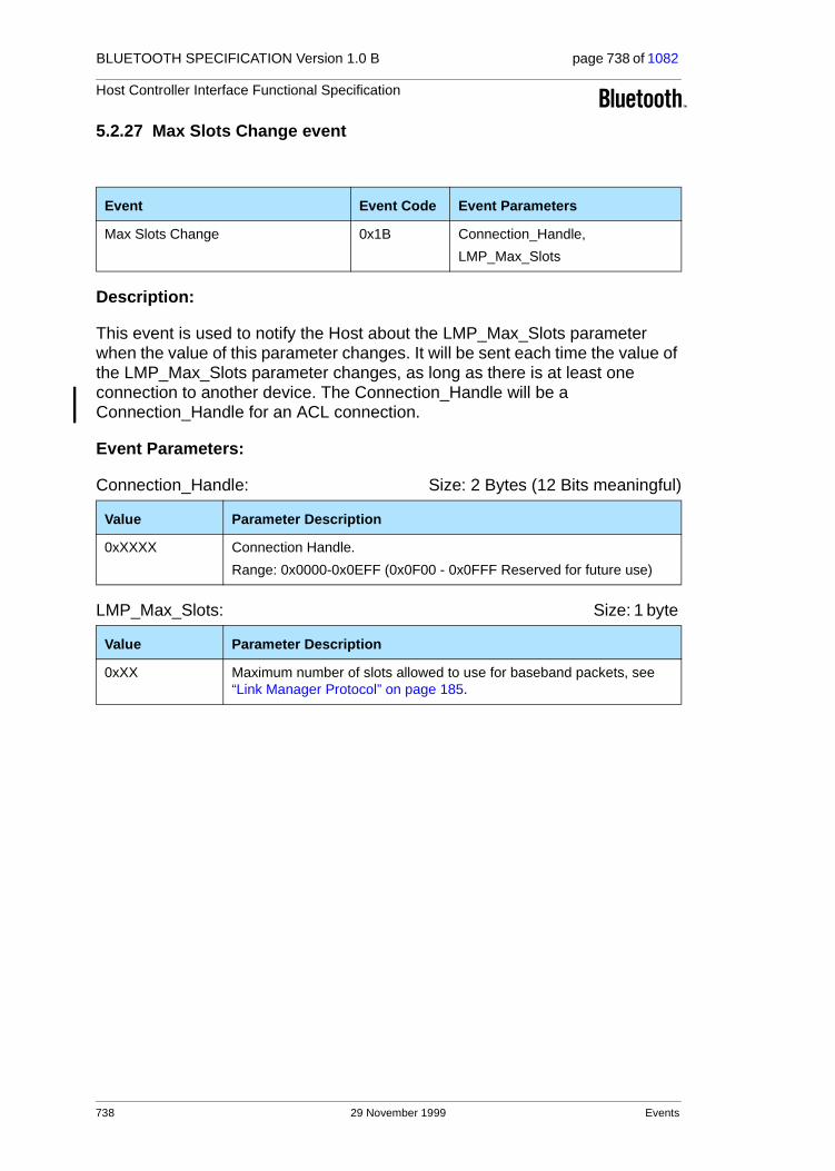
BLUETOOTH SPECIFICATION Version 1.0 B page 738 of 1082
Host Controller Interface Functional Specification
5.2.27 Max Slots Change event
Description:
This event is used to notify the Host about the LMP_Max_Slots parameter when the value of this parameter changes. It will be sent each time the value of the LMP_Max_Slots parameter changes, as long as there is at least one connection to another device. The Connection_Handle will be a Connection_Handle for an ACL connection.
Event Parameters:
Connection_Handle: Size: 2 Bytes (12 Bits meaningful)
LMP_Max_Slots: Size: 1 byte
Event Event Code Event Parameters
Max Slots Change 0x1B Connection_Handle,
LMP_Max_Slots
Value Parameter Description
0xXXXX Connection Handle.
Range: 0x0000-0x0EFF (0x0F00 - 0x0FFF Reserved for future use)
Value Parameter Description
0xXX Maximum number of slots allowed to use for baseband packets, see “Link Manager Protocol” on page 185.
738 29 November 1999 Events

BLUETOOTH SPECIFICATION Version 1.0 B page 739 of 1082
Host Controller Interface Functional Specification
5.2.28 Read Clock Offset Complete event
Description:
The Read Clock Offset Complete event is used to indicate the completion of the process of the Link Manager obtaining the Clock Offset information of the Bluetooth device specified by the Connection_Handle event parameter. The Connection_Handle will be a Connection_Handle for an ACL connection.
Event Parameters:
Status: Size: 1 Byte
Connection_Handle: Size: 2 Bytes (12 bits meaningful)
Clock_Offset: Size: 2 Bytes
Event Event Code Event Parameters
Read Clock Offset Complete 0x1C Status,
Connection_Handle, Clock_Offset
Value Parameter Description
0x00 Read_Clock_Offset command succeeded.
0x01-0xFF Read_Clock_Offset command failed. See Table 6.1 on page 745 for list of Error Codes.
Value Parameter Description
0xXXXX Specifies which Connection Handle’s Clock Offset parameter is returned.
Range: 0x0000-0x0EFF (0x0F00 - 0x0FFF Reserved for future use)
Bit format Parameter Description
Bit 14.0 Bit 16.2 of CLKslave-CLKmaster.
Bit 15 Reserved.
Events 29 November 1999 739

BLUETOOTH SPECIFICATION Version 1.0 B page 740 of 1082
Host Controller Interface Functional Specification
5.2.29 Connection Packet Type Changed event
Description:
The Connection Packet Type Changed event is used to indicate that the pro-cess has completed of the Link Manager changing which packet types can be used for the connection. This allows current connections to be dynamically modified to support different types of user data. The Packet_Type event parameter specifies which packet types the Link Manager can use for the con-nection identified by the Connection_Handle event parameter for sending L2CAP data or voice. The Packet_Type event parameter does not decide which packet types the LM is allowed to use for sending LMP PDUs.
Event Parameters:
Status: Size: 1 Byte
Connection_Handle: Size: 2 Bytes (12 Bits meaningful)
Packet_Type: Size: 2 BytesFor ACL_Link_Type
Event Event Code Event Parameters
Connection Packet Type Changed 0x1D Status,
Connection_Handle, Packet_Type
Value Parameter Description
0x00 Connection Packet Type changed successfully.
0x01-0xFF Connection Packet Type Changed failed. See Table 6.1 on page 745 for list of Error Codes.
Value Parameter Description
0xXXXX Connection Handle. Range: 0x0000-0x0EFF (0x0F00 - 0x0FFF Reserved for future use)
Value Parameter Description
0x0001 Reserved for future use.
0x0002 Reserved for future use.
0x0004 Reserved for future use.
0x0008 DM1
0x0010 DH1
0x0020 Reserved for future use.
0x0040 Reserved for future use.
0x0080 Reserved for future use.
740 29 November 1999 Events
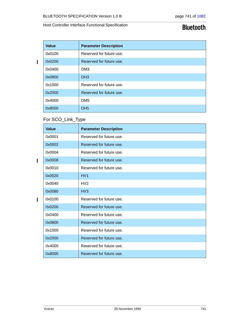
BLUETOOTH SPECIFICATION Version 1.0 B page 741 of 1082
Host Controller Interface Functional Specification
For SCO_Link_Type
Value Parameter Description
0x0100 Reserved for future use.
0x0200 Reserved for future use.
0x0400 DM3
0x0800 DH3
0x1000 Reserved for future use.
0x2000 Reserved for future use.
0x4000 DM5
0x8000 DH5
Value Parameter Description
0x0001 Reserved for future use.
0x0002 Reserved for future use.
0x0004 Reserved for future use.
0x0008 Reserved for future use.
0x0010 Reserved for future use.
0x0020 HV1
0x0040 HV2
0x0080 HV3
0x0100 Reserved for future use.
0x0200 Reserved for future use.
0x0400 Reserved for future use.
0x0800 Reserved for future use.
0x1000 Reserved for future use.
0x2000 Reserved for future use.
0x4000 Reserved for future use.
0x8000 Reserved for future use.
Events 29 November 1999 741

BLUETOOTH SPECIFICATION Version 1.0 B page 742 of 1082
Host Controller Interface Functional Specification
5.2.30 QoS Violation event
Description:
The QoS Violation event is used to indicate the Link Manager is unable to pro-vide the current QoS requirement for the Connection Handle. This event indi-cates that the Link Manager is unable to provide one or more of the agreed QoS parameters. The Host chooses what action should be done. The Host can reissue QoS_Setup command to renegotiate the QoS setting for Connection Handle. The Connection_Handle will be a Connection_Handle for an ACL con-nection.
Event Parameters:
Connection_Handle: Size: 2 Bytes (12 Bits meaningful)
Event Event Code Event Parameters
QoS Violation 0x1E Connection_Handle
Value Parameter Description
0xXXXX Connection Handle that the LM is unable to provide the current QoS requested for.
Range: 0x0000-0x0EFF (0x0F00 - 0x0FFF Reserved for future use)
742 29 November 1999 Events

BLUETOOTH SPECIFICATION Version 1.0 B page 743 of 1082
Host Controller Interface Functional Specification
5.2.31 Page Scan Mode Change event
Description:
The Page Scan Mode Change event indicates that the remote Bluetooth device with the specified BD_ADDR has successfully changed the Page_Scan_Mode.
Event Parameters:
BD_ADDR: Size: 6 Bytes
Page_Scan_Mode: Size: 1 Byte
Event Event Code Event Parameters
Page Scan Mode Change 0x1F BD_ADDR, Page_Scan_Mode
Value Parameter Description
0xXXXXXXXXXXXX
BD_ADDR of the remote device.
Value Parameter Description
0x00 Mandatory Page Scan Mode.
0x01 Optional Page Scan Mode I.
0x02 Optional Page Scan Mode II.
0x03 Optional Page Scan Mode III.
0x04 – 0xFF Reserved.
Events 29 November 1999 743

BLUETOOTH SPECIFICATION Version 1.0 B page 744 of 1082
Host Controller Interface Functional Specification
5.2.32 Page Scan Repetition Mode Change event
Description:
The Page Scan Repetition Mode Change event indicates that the remote Bluetooth device with the specified BD_ADDR has successfully changed the Page_Scan_Repetition_Mode (SR).
Event Parameters:
BD_ADDR: Size: 6 Bytes
Page_Scan_Repetition_Mode: Size: 1 Byte
EventEvent Code Event Parameters
Page Scan Repetition Mode Change 0x20 BD_ADDR,
Page_Scan_Repetition_Mode
Value Parameter Description
0xXXXXXXXXXXXX
BD_ADDR of the remote device.
Value Parameter Description
0x00 R0
0x01 R1
0x02 R2
0x03 – 0xFF Reserved.
744 29 November 1999 Events

BLUETOOTH SPECIFICATION Version 1.0 B page 745 of 1082
Host Controller Interface Functional Specification
6 LIST OF ERROR CODES
6.1 LIST OF ERROR CODES
This section of the document lists the various possible error codes. When a command fails, Error codes are returned to indicate the reason for the error. Error codes have a size of one byte, and the possible range of failure codes is 0x01-0xFF. Section 6.2 provides an error code usage description for each error code.
Error Code
Description
0x01 Unknown HCI Command.
0x02 No Connection.
0x03 Hardware Failure.
0x04 Page Timeout.
0x05 Authentication Failure.
0x06 Key Missing.
0x07 Memory Full.
0x08 Connection Timeout.
0x09 Max Number Of Connections.
0x0A Max Number Of SCO Connections To A Device.
0x0B ACL connection already exists.
0x0C Command Disallowed.
0x0D Host Rejected due to limited resources.
0x0E Host Rejected due to security reasons.
0x0F Host Rejected due to remote device is only a personal device.
0x10 Host Timeout.
0x11 Unsupported Feature or Parameter Value.
0x12 Invalid HCI Command Parameters.
0x13 Other End Terminated Connection: User Ended Connection.
0x14 Other End Terminated Connection: Low Resources.
0x15 Other End Terminated Connection: About to Power Off.
0x16 Connection Terminated by Local Host.
0x17 Repeated Attempts.
List of Error Codes 29 November 1999 745

BLUETOOTH SPECIFICATION Version 1.0 B page 746 of 1082
Host Controller Interface Functional Specification
Table 6.1: List of Possible Error Codes
ErrorCode
Description
0x18 Pairing Not Allowed.
0x19 Unknown LMP PDU.
0x1A Unsupported Remote Feature.
0x1B SCO Offset Rejected.
0x1C SCO Interval Rejected.
0x1D SCO Air Mode Rejected.
0x1E Invalid LMP Parameters.
0x1F Unspecified Error.
0x20 Unsupported LMP Parameter Value.
0x21 Role Change Not Allowed
0x22 LMP Response Timeout
0x23 LMP Error Transaction Collision
0x24 LMP PDU Not Allowed
0x25-0xFF Reserved for Future Use.
746 29 November 1999 List of Error Codes

BLUETOOTH SPECIFICATION Version 1.0 B page 747 of 1082
Host Controller Interface Functional Specification
6.2 HCI ERROR CODE USAGE DESCRIPTIONS
The purpose of this section is to give descriptions of how the error codes specified in Table 6.1 on page 745 should be used. It is beyond the scope of this document to give detailed descriptions of all situations where error codes can be used – especially as this may also, in certain cases, be implementation-dependent. However, some error codes that are to be used only in very special cases are described in more detail than other, more general, error codes.
The following error codes are only used in LMP messages, and are therefore not described in this section:
• Unknown LMP PDU (0x19)
• SCO Offset Rejected (0x1B)
• SCO Interval Rejected (0x1C)
• SCO Air Mode Rejected (0x1D)
• Invalid LMP Parameters (0x1E)
Some of the following error code descriptions describe as implementation-dependent whether the error should be returned using a Command Status event or the event associated with the issued command (following a Command Status event with Status=0x00). In these cases, the command can not start executing because of the error, and it is therefore recommended to use the Command Status event. The reason for this suggested course of action is that it is not possible to use the Command Status event in all software architec-tures.
6.3 UNKNOWN HCI COMMAND (0X01)
The ‘Unknown HCI Command’ error code is returned by the Host Controller in the Status parameter in a Command Complete event or a Command Status event when the Host Controller receives an HCI Command Packet with an Opcode that it does not recognize. The OpCode given might not correspond to any of the OpCodes specified in this document, or any vendor-specific OpCodes, or the command may not have been implemented. If a Command Complete event is returned, the Status parameter is the only parameter con-tained in the Return_Parameters event parameter. Which of the two events is used is implementation-dependent.
List of Error Codes 29 November 1999 747

BLUETOOTH SPECIFICATION Version 1.0 B page 748 of 1082
Host Controller Interface Functional Specification
6.4 NO CONNECTION (0X02)
The ‘No Connection’ error code is returned by the Host Controller in the Status parameter in an event when the Host has issued a command which requires an existing connection and there is currently no connection corresponding to the specified Connection Handle or BD Address. If the issued command is a com-mand for which a Command Complete event should be returned, the event containing the error code is a Command Complete event. Otherwise, the event containing the error code is a Command Status event or the event associated with the issued command (following a Command Status event with Status=0x00), depending on the implementation.
6.5 HARDWARE FAILURE (0X03)
The ’Hardware Failure’ error code is returned by the Host Controller in the Status parameter in an event when the Host has issued a command and this command can not be executed because of a hardware failure. If the issued command is a command for which a Command Complete event should be returned, the event containing the error code is a Command Complete event. Otherwise, the event containing the error code is a Command Status event or the event associated with the issued command (following a Command Status event with Status=0x00) depending on the implementation.
6.6 PAGE TIMEOUT (0X04)
The ’Page Timeout’ error code is returned by the Host Controller in the Status parameter of the Connection Complete event when the Host has issued a Create_Connection command and the specified device to connect to does not respond to a page at baseband level before the page timer expires (a page tim-eout occurs). The error code can also be returned in the Status parameter of a Remote Name Request Complete event when the Host has issued a Remote_Name_Request command and a temporary connection needs to be established but a page timeout occurs. (The page timeout is set using the Write_Page_Timeout command.)
6.7 AUTHENTICATION FAILED (0X05)
The ’Authentication Failed’ error code is returned by the Host Controller in the Status parameter in a Connection Complete event or Authentication Complete event when pairing or authentication fails due to incorrect results in the pairing/authentication calculations (because of incorrect PIN code or link key).
6.8 KEY MISSING (0X06)
The ’Key Missing’ error code is returned by the Host Controller in the Status parameter in a Connection Complete event or Authentication Complete event when pairing fails because of missing PIN code(s).
748 29 November 1999 List of Error Codes
BLUETOOTH SPECIFICATION Version 1.0 B page 749 of 1082
Host Controller Interface Functional Specification
6.9 MEMORY FULL (0X07)
The ’Memory Full’ error code is returned by the Host Controller in the Status parameter in a Command Complete event when the Host has issued a com-mand that requires the Host Controller to store new parameters and the Host Controller does not have memory capacity for this. This may be the case after the Set_Event_Filter command has been issued. Note that for the Write_Stored_Link_Key command, no error is returned when the Host Control-ler can not store any more link keys. The Host Controller stores as many link keys as there is free memory to store in, and the Host is notified of how many link keys were successfully stored.
6.10 CONNECTION TIMEOUT (0X08)
Note: this error code is used to indicate a reason for disconnection. It is nor-mally returned in the Reason parameter of a Disconnection Complete event. It is therefore called reason code in the following description.
The ’Connection Timeout’ reason code is sent by the Host Controller in an event when the link supervision timer (see “Baseband Timers” on page 993) expires and the link therefore is considered to be lost. The link supervision tim-eout is set using Write_Link_Supervision_Timeout. The event that returns this reason code will most often be a Disconnection Complete event (in the Reason parameter). The event will be returned on both sides of the connection, where one Disconnection Complete event will be sent from the Host Controller to the Host for each Connection Handle that exists for the physical link to the other device.
(It is possible for a link loss to be detected during connection set up, in which case the reason code would be returned in a Connection Complete event.)
6.11 MAX NUMBER OF CONNECTIONS (0X09)
The ’Max Number Of Connections’ error code is returned by the Host Control-ler in the Status parameter of a Command Status event, a Connection Com-plete event or a Remote Name Request Complete event when the Bluetooth module can not establish any more connections. It is implementation specific whether the error is returned in a Command Status event or the event following the Command Status event (where Status=0x00 in the Command Status event). The reason for this error may be hardware or firmware limitations. Before the error is returned, the Host has issued a Create_Connection, Add_SCO_Connection or Remote_Name_Request command. The error can be returned in a Remote Name Request Complete event when a temporary connection needs to be established to request the name.
List of Error Codes 29 November 1999 749
BLUETOOTH SPECIFICATION Version 1.0 B page 750 of 1082
Host Controller Interface Functional Specification
6.12 MAX NUMBER OF SCO CONNECTIONS TO A DEVICE (0X0A)
The ’Max Number Of SCO Connections To A Device’ error code is returned by the Host Controller in the Status parameter of a Command Status event or a Connection Complete event (following a Command Status event with Status=0x00) when the maximum number of SCO connections to a device has been reached. Which of the two events that is used depends on the implemen-tation. The device is a device that has been specified in a previously issued Add_SCO_Connection command.
6.13 ACL CONNECTION ALREADY EXISTS (0X0B)
The ’ACL connection already exists’ error code is returned by the Host Control-ler in the Status parameter of a Command Status event or a Connection Com-plete event (following a Command Status event with Status=0x00) when there already is one ACL connection to a device and the Host tries to establish another one using Create_Connection. Which of the two events that is used depends on the implementation.
6.14 COMMAND DISALLOWED (0X0C)
The ’Command Disallowed’ error code is returned by the Host Controller in the Status parameter in a Command Complete event or a Command Status event when the Host Controller is in a state where it is only prepared to accept com-mands with certain OpCodes and the HCI Command Packet received does not contain any of these OpCodes. The Command Complete event should be used if the issued command is a command for which a Command Complete event should be returned. Otherwise, the Command Status event should be used. The Host Controller is not required to use the ’Unknown HCI Command’ error code, since this may require unnecessary processing of the received (and cur-rently not allowed) OpCode. When to use the ’Command Disallowed’ error code is mainly implementation-dependent. Certain implementations may, for example, only accept the appropriate HCI response commands after the Con-nection Request, Link Key Request or PIN Code Request events. Note: the Reset command should always be allowed.
6.15 HOST REJECTED DUE TO … (0X0D-0X0F)
Note: these error codes are used to indicate a reason for rejecting an incoming connection. They are therefore called reason codes in the following descrip-tion.
When a Connection Request event has been received by the Host and the Host rejects the incoming connection by issuing the Reject_Connection_Request command, one of these reason codes is used as value for the Reason parameter. The issued reason code will be returned in the Status parameter of the Connection Complete event that will follow the Command Status event
750 29 November 1999 List of Error Codes

BLUETOOTH SPECIFICATION Version 1.0 B page 751 of 1082
Host Controller Interface Functional Specification
(with Status=0x00) returned by the Host Controller after the Reject_Connection_Request command has been issued. The reason code issued in the Reason parameter of the Reject_Connection_Request command will also be sent over the air, so that it is returned in a Connection Complete event on the initiating side. Before this, the initiating side has issued a Create_Connection command or Add_SCO_Connection command, and has received a Command Status event (with Status=0x00).
6.16 HOST TIMEOUT (0X10)
Note: this error code is used to indicate a reason for rejecting an incoming con-nection. It is therefore called reason code in the following description.
Assume that a Connection Request event has been received by the Host and that the Host does not issue the Accept_Connection_Request or Reject_Connection_Request command before the connection accept timer expires (the connection accept timeout is set using Write_Connection_Accept_Timeout). In this case, the ’Host Timeout’ reason code will be sent by the Host Controller in the Status parameter of a Connection Complete event. The rea-son code will also be sent over the air, so that it is returned in a Connection Complete event on the initiating side. The initiating side has before this issued a Create_Connection or Add_SCO_Connection command and has received a Command Status event (with Status=0x00).
6.17 UNSUPPORTED FEATURE OR PARAMETER VALUE (0X11)
The ’Unsupported Feature or Parameter Value’ error code is returned by the Host Controller in the Status parameter in an event when the Host Controller has received a command where one or more parameters have values that are not supported by the hardware (the parameters are, however, within the allowed parameter range specified in this document). If the issued command is a command for which a Command Complete event should be returned, the event containing the error code is a Command Complete event. Otherwise, the event containing the error code is a Command Status event or the event associated with the issued command (following a Command Status event with Status=0x00) depending on the implementation.
6.18 INVALID HCI COMMAND PARAMETERS (0X12)
The ’Invalid HCI Command Parameters’ error code is returned by the Host Controller in the Status parameter of an event when the total parameter length (or the value of one or more parameters in a received command) does not con-form to what is specified in this document.
The error code can also be returned if a parameter value is currently not allowed although it is inside the allowed range for the parameter. One case is when a command requires a Connection Handle for an ACL connection but the
List of Error Codes 29 November 1999 751

BLUETOOTH SPECIFICATION Version 1.0 B page 752 of 1082
Host Controller Interface Functional Specification
Host has given a Connection Handle for an SCO connection as a parameter instead. Another case is when a link key, a PIN code or a reply to an incoming connection has been requested by the Host Controller by using an event but the Host replies using a response command with a BD_ADDR for which no request has been made.
If the issued command is a command for which a Command Complete event should be returned, the event containing the error code is a Command Com-plete event. Otherwise, the event containing the error code is a Command Sta-tus event or the event associated with the issued command (following a Command Status event with Status=0x00), depending on the implementation.
6.19 OTHER END TERMINATED CONNECTION: … (0X13-0X15)
Note: these error codes are used to indicate a reason for disconnecting a con-nection. They are therefore called reason codes in the following description.
When the Host issues the Disconnect command, one of these reason codes is used as value for the reason parameter. The ’Connection Terminated By Local Host’ reason code will then be returned in the Reason parameter of the Discon-nection Complete event that will follow the Command Status event (with Sta-tus=0x00) that is returned by the Host Controller after the Disconnect command has been issued. The reason code issued in the Reason parameter of the Disconnect command will also be sent over the air, so that it is returned in the Reason parameter of a Disconnection Complete event on the remote side.
6.20 CONNECTION TERMINATED BY LOCAL HOST (0X16)
See description in 6.19. This error code is called a reason code, since it is returned in the Reason parameter of a Disconnection Complete event.
6.21 REPEATED ATTEMPTS (0X17)
The ’Repeated Attempts’ error code is returned by the Host Controller in the Status parameter in a Connection Complete event or Authentication Complete event when a device does not allow authentication or pairing because too little time has elapsed since an unsuccessful authentication or pairing attempt. See “Link Manager Protocol” on page 185 for a description of how repeated attempts work.
6.22 PAIRING NOT ALLOWED (0X18)
The ’Pairing Not Allowed’ error code is returned by the Host Controller in the Status parameter in a Connection Complete event or Authentication Complete event when a device for some reason does not allow pairing. An example may be a PSTN adapter that only allows pairing during a certain time window after a button has been pressed on the adapter.
752 29 November 1999 List of Error Codes
BLUETOOTH SPECIFICATION Version 1.0 B page 753 of 1082
Host Controller Interface Functional Specification
6.23 UNSUPPORTED REMOTE FEATURE (0X1A)
The ’Unsupported Remote Feature’ error code is returned by the Host Control-ler in the Status parameter of the event associated with the issued command when a remote device that has been specified in the command parameters does not support the feature associated with the issued command. The ’Unsupported Remote Feature’ error code can also be used as a value for the Reason parameter in the Disconnect command (as a reason code). The error code will then be sent over the air so that it is returned in the Reason parame-ter of a Disconnection Complete event on the remote side. In the Disconnec-tion Complete event following a Command Status event (where Status=0x00) on the local side on which the Disconnect command has been issued, the Rea-son parameter will however contain the reason code ’Connection Terminated By Local Host’. (The ’Unsupported Remote Feature’ error code is called ’Unsupported LMP Feature’ in the LMP specification, see “Link Manager Proto-col” on page 185.)
6.24 UNSPECIFIED ERROR (0X1F)
The ’Unspecified error’ error code is used when no other error code specified in this document is appropriate to use.
6.25 UNSUPPORTED LMP PARAMETER VALUE (0X20)
The ’Unsupported LMP Parameter Value’ error code is returned by the Host Controller in the Status parameter of the event associated with the issued com-mand when a remote device that has been specified in the command parame-ters sent back an LMP message containing the LMP error code 0x20, ’Unsupported parameter values’ (see “Link Manager Protocol” on page 185).
6.26 ROLE CHANGE NOT ALLOWED (0X21)
The ’Role Change Not Allowed’ error code is returned by the Host Controller in the Status parameter in a Connection Complete event or Role Change event when role change is not allowed. If the local Host issues the Switch_Role com-mand and the remote device rejects the role change, the error code will be returned in a Role Change event. If a connection fails because a device accepts an incoming ACL connection with a request for role change and the role change is rejected by the initiating device, the error code will be returned in a Connection Complete event on both sides.
6.27 LMP RESPONSE TIMEOUT (0X22)
The ’LMP Response Timeout’ error code is returned by the Host Controller in the Status parameter in a Command Complete event or an event associated with the issued command following a Command Status event with Sta-tus=0x00, when the remote device does not respond to the LMP PDUs from
List of Error Codes 29 November 1999 753

BLUETOOTH SPECIFICATION Version 1.0 B page 754 of 1082
Host Controller Interface Functional Specification
the local device as a result of the issued command within LMP response time-out. (See “Link Manager Protocol” on page 185)
6.28 LMP ERROR TRANSACTION COLLISION (0X23)
The ’LMP Error Transaction Collision’ error code is returned by the Host Con-troller in the Status parameter of the event associated with the issued com-mand when a remote device that has been specified in the command parameters sends back an LMP message containing the LMP error code 0x23, "LMP Error Transaction Collision" (see “Link Manager Protocol” on page 185).
6.29 LMP PDU NOT ALLOWED (0X24)
The ’LMP PDU Not Allowed’ error code is returned by the Host Controller in the Status parameter of the event associated with the issued command when a remote device that has been specified in the command parameters sends back an LMP message containing the LMP error code 0x24, "PDU Not Allowed" (see “Link Manager Protocol” on page 185).
754 29 November 1999 List of Error Codes

BLUETOOTH SPECIFICATION Version 1.0 B page 755 of 1082
Host Controller Interface Functional Specification
7 LIST OF ACRONYMS AND ABBREVIATIONS
Acronym or abbreviation
Complete name
ACL Asynchronous Connection Less
BD_ADDR Bluetooth Device Address
DH Data High rate
DIAC Dedicated Inquiry Access Code
DM Data Medium rate
DUT Device Under Test
DV Data Voice
GIAC General Inquiry Access Code
HCI Host Controller Interface
L2CAP Logical Link Control and Adaptation Protocol
L_CH Logical Channel
LAP Lower Address Part
LC Link Controller
LM Link Manager
LMP Link Manager Protocol
OCF Opcode Command Field
OGF OpCode Group Field
RF Radio Frequency
RSSI Received Signal Strength Indication
SCO Synchronous Connection Oriented
TBD To Be Defined
UA User Asynchronous
UI User Isochronous
US User Synchronous
USB Universal Serial Bus
Table 7.1: List of Acronyms and Abbreviations
List of Acronyms and Abbreviations 29 November 1999 755

BLUETOOTH SPECIFICATION Version 1.0 B page 756 of 1082
Host Controller Interface Functional Specification
8 LIST OF FIGURES
Figure 1.1: Overview of the Lower Software Layers ..................................524Figure 1.2: End to End Overview of Lower Software Layers
to Transfer Data .......................................................................525Figure 1.3: Bluetooth Hardware Architecture Overview. ............................526Figure 1.4: Bluetooth Block Diagram with USB HCI ..................................527Figure 1.5: Bluetooth Block Diagram with PC-Card HCI............................527Figure 4.1: HCI Command Packet .............................................................534Figure 4.2: HCI Event Packet ....................................................................535Figure 4.3: HCI ACL Data Packet ..............................................................536Figure 4.4: HCI SCO Data Packet .............................................................538Figure 4.5: Local Loopback Mode..............................................................697Figure 4.6: Remote Loopback Mode..........................................................697Figure 4.7: Local Loopback Mode..............................................................700Figure 4.8: Remote Loopback Mode..........................................................700
756 29 November 1999 List of Figures

BLUETOOTH SPECIFICATION Version 1.0 B page 757 of 1082
Host Controller Interface Functional Specification
9 LIST OF TABLES
Table 5.1: List of Supported Events ..........................................................703Table 6.1: List of Possible Error Codes.....................................................746Table 7.1: List of Acronyms and Abbreviations.........................................755
List of Tables 29 November 1999 757

BLUETOOTH SPECIFICATION Version 1.0 B page 758 of 1082
Host Controller Interface Functional Specification
758 29 November 1999 List of Tables

Part H:2
HCI USB TRANSPORT LAYER
An addendum to the HCI document
This document describes the USB transport layer (between a host and the host controller). HCI commands flow through this layer, but the layer does not decode the commands.

BLUETOOTH SPECIFICATION Version 1.0 B page 760 of 1082
HCI USB Transport Layer
760 29 November 1999

BLUETOOTH SPECIFICATION Version 1.0 B page 761 of 1082
HCI USB Transport Layer
CONTENTS
1 Overview ...........................................................................................762
2 USB Endpoint Expectations............................................................7642.1 Descriptor Overview.................................................................7642.2 Control Endpoint Expectations.................................................7692.3 Bulk Endpoints Expectations....................................................7692.4 Interrupt Endpoint Expectations...............................................7692.5 Isochronous Endpoints Expectations.......................................770
3 Class Code........................................................................................771
4 Device Firmware Upgrade ...............................................................772
5 Limitations ........................................................................................7735.1 Power Specific Limitations .......................................................7735.2 Other Limitations......................................................................773
29 November 1999 761

BLUETOOTH SPECIFICATION Version 1.0 B page 762 of 1082
HCI USB Transport Layer
1 OVERVIEW
This document discusses the requirements of the Universal Serial Bus (USB) interface for Bluetooth hardware. Readers should be familiar with USB, USB design issues, Advanced Configuration Power Interface (ACPI), the overall Bluetooth architecture, and the basics of the radio interface.
The reader should also be familiar with the Bluetooth Host Controller Interface.
Referring to Figure 1.1 below, notice that this document discusses the imple-mentation details of the two-way arrow labelled ’USB Function’.
Figure 1.1: The Figure illustrates the relationship between the host and the Bluetooth Radio Module
The USB hardware can be embodied in one of two ways:
1. As a USB dongle, and
2. Integrated onto the motherboard of a notebook PC.
Bluetooth Radio ModuleNotebook PC
RFBD (with Bluetooth HCI Library)
USB DeviceController
Bluetooth USB Firmware
Bluetooth HCI Firmware
USB Host Controller
Microsoft USB Stack
RFUSB (USB Minidriver)
USB Cable
USB Function
Other Host DriversBaseband Controller
LMP Firmware
Bluetooth HCI
762 29 November 1999 Overview
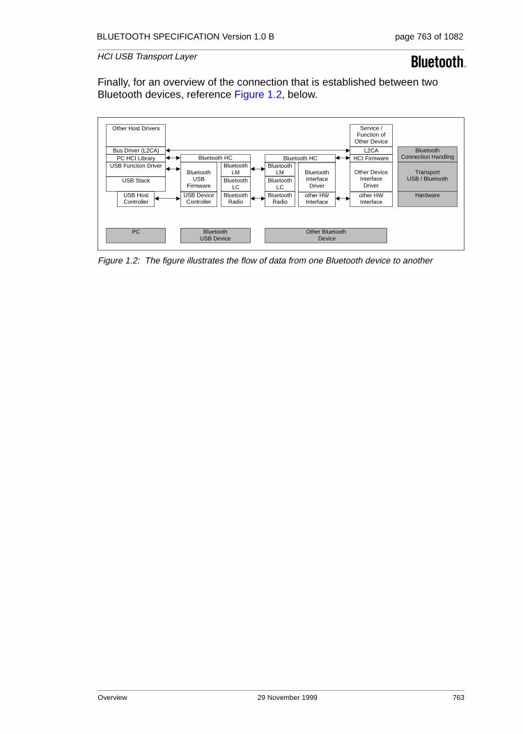
BLUETOOTH SPECIFICATION Version 1.0 B page 763 of 1082
HCI USB Transport Layer
Finally, for an overview of the connection that is established between two Bluetooth devices, reference Figure 1.2, below.
Figure 1.2: The figure illustrates the flow of data from one Bluetooth device to another
Bus Driver (L2CA)PC HCI Library
Other Host Drivers
USB Function Driver
USB Stack
USB HostController
Bluetooth HC
BluetoothUSB
Firmware
USB DeviceController
BluetoothLM
BluetoothLC
BluetoothRadio
L2CA
BluetoothInterface
Driver
BluetoothLM
BluetoothLC
BluetoothRadio
BluetoothUSB Device
PC Other Bluetooth Device
other HWInterface
other HWInterface
Other DeviceInterface
Driver
HCI Firmware
Hardware
TransportUSB / Bluetooth
Bluetooth HC
Service /Function of
Other Device
BluetoothConnection Handling
Overview 29 November 1999 763
BLUETOOTH SPECIFICATION Version 1.0 B page 764 of 1082
HCI USB Transport Layer
2 USB ENDPOINT EXPECTATIONS
This section outlines specific USB endpoints that are required in order to func-tion properly with the host. This section assumes a basic familiarity with USB. The endpoint numbers (labelled ’Suggested Endpoint Address’ below) may be dynamically recognized upon driver initialization – this depends on the imple-mentation.
2.1 DESCRIPTOR OVERVIEW
The USB device is expected to be a high-speed device.
The firmware configuration consists of two interfaces. The first interface (inter-face zero) has no alternate settings and contains the bulk and interrupt end-points. The second interface (interface one) provides scalable isochronous bandwidth consumption. The second interface has four alternate settings that provide different consumption based on the required isochronous bandwidth. The default interface is empty so that the device is capable of scaling down to no isochronous bandwidth.
An HCI frame - consisting of an HCI header and HCI data - should be con-tained in one USB transaction. A USB transaction is defined as one or more USB frames that contain the data from one IO request. For example, an ACL data packet containing 256 bytes (both HCI header and HCI data) would be sent over the bulk endpoint in one IO request. That IO request will require four 64-byte USB frames - and forms a transaction.
The endpoints are spread across two interfaces so, when adjusting isochro-nous bandwidth consumption (via select interface calls), any pending bulk and/or interrupt transactions do not have to be terminated and resubmitted.
764 29 November 1999 USB Endpoint Expectations

BLUETOOTH SPECIFICATION Version 1.0 B page 765 of 1082
HCI USB Transport Layer
The following table outlines the required configuration
Interface Number
Alternate Setting
Suggested Endpoint Address
Endpoint Type
Suggested Max Packet Size
HCI Commands
0 0 0x00 Control 8/16/32/64
HCI Events
0 0 0x81 Interrupt (IN) 16
ACL Data
0 0 0x82 Bulk (IN) 32/64
0 0 0x02 Bulk (OUT) 32/64
No active voice channels (for USB compliance)
1 0 0x83 Isoch (IN) 0
1 0 0x03 Isoch (OUT) 0
One voice channel with 8-bit encoding
1 1 0x83 Isoch (IN) 9
1 1 0x03 Isoch (OUT) 9
Two voice channels with 8-bit encoding & One voice channel with 16-bit encoding
1 2 0x83 Isoch (IN) 17
1 2 0x03 Isoch (OUT) 17
Three voice channels with 8-bit encoding
1 3 0x83 Isoch (IN) 25
1 3 0x03 Isoch (OUT) 25
Two voice channels with 16-bit encoding
1 4 0x83 Isoch (IN) 33
1 4 0x03 Isoch (OUT) 33
Three voice channels with 16-bit encoding
1 5 0x83 Isoch (IN) 49
1 5 0x03 Isoch (OUT) 49
USB Endpoint Expectations 29 November 1999 765

BLUETOOTH SPECIFICATION Version 1.0 B page 766 of 1082
HCI USB Transport Layer
The following two examples are used to demonstrate the flow of data given the describe endpoints.
Number of voicechannels Duration of voice data Encoding
One 3 ms per IO Request 8-bit
Time(ms
USB data (header refers to HCI header)(Receive & Send from the host)
Queued data (read / write)
Time(ms) Air data
AmountReceived /Sent (ms)
0 Receive 0 bytes
Send 9 bytes (3 header, 6 data)
0 / 6 0 Send 0 0 / 0
10 / 6 0.625 Receive 10 1.25 / 0
1 Receive 0 bytes
Send 9 bytes (9 bytes HCI data)
10 / 15 1.25 Send 0 1.25 / 0
20 / 15 1.875 Receive 10 2.50 / 0
2 Receive 0 bytes
Send 9 bytes (9 bytes HCI data)
20 / 24 2.50 Send 0 2.50 / 0
30 / 24 3.125 Receive 10 3.75 / 0
3 Receive 9 bytes (3 header, 6 data)
Send 9 bytes (3 header, 6 data)
24 / 20 3.75 Send 10 3.75 / 1.25
4 Receive 9 bytes (9 bytes data)
Send 9 bytes (9 bytes HCI data)
25 / 29 4.375 Receive 10 5.0 / 1.25
5 Receive 9 bytes (9 bytes data)
Send 9 bytes (9 bytes HCI data)
16 / 28 5.0 Send 10 5.0 / 2.50
26 / 28 5.625 Receive 10 6.25 / 2.50
6 Receive 9 bytes (3 header, 6 data)
Send 9 bytes (3 header, 6 data)
20 / 24 6.25 Send 10 6.25 / 3.75
30 / 24 6.875 Receive 10 7.5 / 3.75
7 Receive 9 bytes (9 bytes data)
Send 9 bytes (9 bytes HCI data)
21 / 23 7.5 Send 10 7.5 / 5.0
8 Receive 9 bytes (9 bytes data)
Send 9 bytes (9 bytes HCI data)
22 / 32 8.125 Receive 10 8.75 / 5.0
22 / 22 8.75 Send 10 8.75 / 6.25
9 Receive 9 bytes (3 header, 6 data)
Send 9 bytes (3 header, 6 data)
26 / 28 9.375 Receive 10 10.0 / 6.25
Table 2.1:
766 29 November 1999 USB Endpoint Expectations

BLUETOOTH SPECIFICATION Version 1.0 B page 767 of 1082
HCI USB Transport Layer
Convergence is expected because the radio is sending out an average of 8 bytes of voice data every 1 ms and USB is sending 8 bytes of voice data every 1 ms.
10 Receive 9 bytes (9 bytes data)
Send 9 bytes (9 bytes HCI data)
17 / 27 10 Send 10 10.0 / 7.5
27 / 27 10.625 Receive 10 11.25 / 7.5
11 Receive 9 bytes (9 bytes data)
Send 9 bytes (9 bytes HCI data)
18 / 26 11.25 Send 10 11.25 / 8.75
Number of voice channels Duration of voice data Encoding
Two 3 ms per IO Request 8-bit
Time(ms
USB data (header refers to HCI header)(Receive & Send from the host)
Queueddata (read/ write)
Time(ms)
Air dataAmountReceived /Sent (ms)
0 Receive 0 bytes for Channel #1
Send 17 bytes (3 header, 14 data) for Channel #1
C1- 0/14
C2- 0/0
0 Send 0 for C1
C1- 0/0
C2- 0/0
C1- 20/14
C2- 0/0
0.625 Receive 20 for C1
C1- 2.5/0
C2- 0/0
1 Receive 0 bytes for Channel #1
Send 17 bytes (17 bytes HCI data) for Channel #1
C1- 20/31
C2- 0/0
1.25 Send 0 for C2
C1- 2.5/0
C2- 0/0
C1- 20/31
C2- 20/0
1.875 Receive 20 for C2
C1- 2.5/0
C2- 2.5/0
2 Receive 0 bytes for Channel #1
Send 17 bytes (17 bytes HCI data) for Channel #1
C1- 20/28
C2- 20/0
2.50 Send 20 for C1
C1- 2.5/2.5
C2- 2.5/0
C1- 40/28
C2- 0/0
3.125 Receive 20 for C1
C1- 5.0/2.5
C2- 2.5/0
Table 2.2:
Time(ms
USB data (header refers to HCI header)(Receive & Send from the host)
Queued data (read / write)
Time(ms)
Air dataAmountReceived /Sent (ms)
Table 2.1:
USB Endpoint Expectations 29 November 1999 767
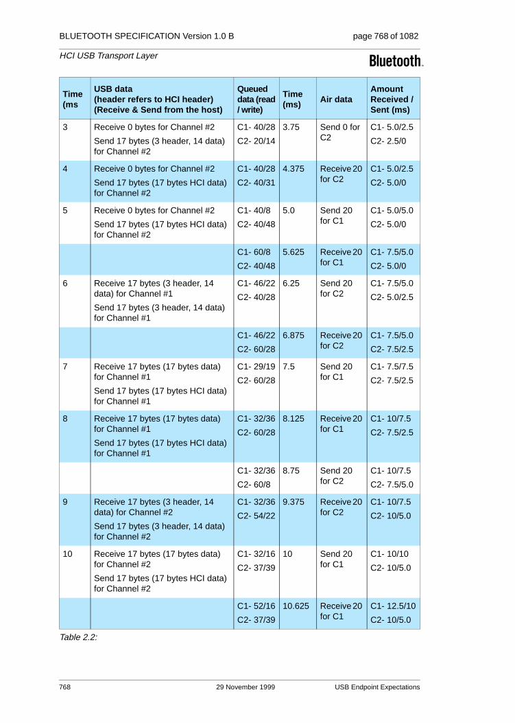
BLUETOOTH SPECIFICATION Version 1.0 B page 768 of 1082
HCI USB Transport Layer
3 Receive 0 bytes for Channel #2
Send 17 bytes (3 header, 14 data) for Channel #2
C1- 40/28
C2- 20/14
3.75 Send 0 for C2
C1- 5.0/2.5
C2- 2.5/0
4 Receive 0 bytes for Channel #2
Send 17 bytes (17 bytes HCI data) for Channel #2
C1- 40/28
C2- 40/31
4.375 Receive 20 for C2
C1- 5.0/2.5
C2- 5.0/0
5 Receive 0 bytes for Channel #2
Send 17 bytes (17 bytes HCI data) for Channel #2
C1- 40/8
C2- 40/48
5.0 Send 20 for C1
C1- 5.0/5.0
C2- 5.0/0
C1- 60/8
C2- 40/48
5.625 Receive 20 for C1
C1- 7.5/5.0
C2- 5.0/0
6 Receive 17 bytes (3 header, 14 data) for Channel #1
Send 17 bytes (3 header, 14 data) for Channel #1
C1- 46/22
C2- 40/28
6.25 Send 20 for C2
C1- 7.5/5.0
C2- 5.0/2.5
C1- 46/22
C2- 60/28
6.875 Receive 20 for C2
C1- 7.5/5.0
C2- 7.5/2.5
7 Receive 17 bytes (17 bytes data) for Channel #1
Send 17 bytes (17 bytes HCI data) for Channel #1
C1- 29/19
C2- 60/28
7.5 Send 20 for C1
C1- 7.5/7.5
C2- 7.5/2.5
8 Receive 17 bytes (17 bytes data) for Channel #1
Send 17 bytes (17 bytes HCI data) for Channel #1
C1- 32/36
C2- 60/28
8.125 Receive 20 for C1
C1- 10/7.5
C2- 7.5/2.5
C1- 32/36
C2- 60/8
8.75 Send 20 for C2
C1- 10/7.5
C2- 7.5/5.0
9 Receive 17 bytes (3 header, 14 data) for Channel #2
Send 17 bytes (3 header, 14 data) for Channel #2
C1- 32/36
C2- 54/22
9.375 Receive 20 for C2
C1- 10/7.5
C2- 10/5.0
10 Receive 17 bytes (17 bytes data) for Channel #2
Send 17 bytes (17 bytes HCI data) for Channel #2
C1- 32/16
C2- 37/39
10 Send 20 for C1
C1- 10/10
C2- 10/5.0
C1- 52/16
C2- 37/39
10.625 Receive 20 for C1
C1- 12.5/10
C2- 10/5.0
Time(ms
USB data (header refers to HCI header)(Receive & Send from the host)
Queueddata (read/ write)
Time(ms) Air data
AmountReceived /Sent (ms)
Table 2.2:
768 29 November 1999 USB Endpoint Expectations

BLUETOOTH SPECIFICATION Version 1.0 B page 769 of 1082
HCI USB Transport Layer
2.2 CONTROL ENDPOINT EXPECTATIONS
Endpoint 0 is used to configure and control the USB device. Endpoint 0 will also be used to allow the host to send HCI-specific commands to the host con-troller. When the USB firmware receives a packet over this endpoint that has the Bluetooth class code, it should treat the packet as an HCI command packet.
2.3 BULK ENDPOINTS EXPECTATIONS
Data integrity is a critical aspect for ACL data. This, in combination with band-width requirements, is the reason for using a bulk endpoint. Multiple 64-byte packets can be shipped, per millisecond, across the bus.
Suggested bulk max packet size is 64 bytes. Bulk has the ability to transfer multiple 64-byte buffers per one millisecond frame, depending on available bus bandwidth.
Bulk has the ability to detect errors and correct them. Data flowing through this pipe might be destined for several different slaves. In order to avoid starvation, a flow control model similar to the shared endpoint model is recommended for the host controller.
2.4 INTERRUPT ENDPOINT EXPECTATIONS
An interrupt endpoint is necessary to ensure that events are delivered in a pre-dictable and timely manner. Event packets can be sent across USB with a guaranteed latency.
The interrupt endpoint should have an interval of 1 ms.
The USB software and firmware requires no intimate knowledge of the events passed to the host controller.
11 Receive 17 bytes (17 bytes data) for Channel #2
Send 17 bytes (17 bytes HCI data) for Channel #2
C1- 52/16
C2- 20/36
11.25 Send 20 for C2
C1- 12.5/10
C2- 10/7.5
Time(ms
USB data (header refers to HCI header)(Receive & Send from the host)
Queueddata (read/ write)
Time(ms) Air data
AmountReceived /Sent (ms)
Table 2.2:
USB Endpoint Expectations 29 November 1999 769

BLUETOOTH SPECIFICATION Version 1.0 B page 770 of 1082
HCI USB Transport Layer
2.5 ISOCHRONOUS ENDPOINTS EXPECTATIONS
These isochronous endpoints transfer SCO data to and from the host controller of the radio.
Time is the critical aspect for this type of data. The USB firmware should trans-fer the contents of the data to the host controllers’ SCO FIFOs. If the FIFOs are full, the data should be overwritten with new data.
These endpoints have a one (1) ms interval, as required by Chapter 9 of the USB Specification, Versions 1.0 and 1.1.
The radio is capable of three (3) 64Kb/s voice channels (and can receive the data coded in different ways – 16-bit linear audio coding is the method that requires the most data). A suggested max packet size for this endpoint would be at least 64 bytes. (It is recommended that max packet sizes be on power of 2 boundaries for optimum throughput.) However, if it is not necessary to sup-port three voice channels with 16-bit coding, 32 bytes could also be considered an acceptable max packet size.
770 29 November 1999 USB Endpoint Expectations

BLUETOOTH SPECIFICATION Version 1.0 B page 771 of 1082
HCI USB Transport Layer
3 CLASS CODE
A class code will be used that is specific to all USB Bluetooth devices. This will allow the proper driver stack to load, regardless of which vendor built the device. It also allows HCI commands to be differentiated from USB commands across the control endpoint.
The class code (bDeviceClass) is 0xE0 – Wireless Controller.
The SubClass code (bDeviceSubClass) is 0x01 – RF Controller.
The Protocol code (bDeviceProtocol) is 0x01 – Bluetooth programming.
Class Code 29 November 1999 771
BLUETOOTH SPECIFICATION Version 1.0 B page 772 of 1082
HCI USB Transport Layer
4 DEVICE FIRMWARE UPGRADE
Firmware upgrade capability is not a required feature. But if implemented, the firmware upgrade shall be compliant with the "Universal Serial Bus Device Class Specification for Device Firmware Upgrade" (version 1.0 dated May 13, 1999) available on the USB Forum web site at http://www.usb.org.
772 29 November 1999 Device Firmware Upgrade

BLUETOOTH SPECIFICATION Version 1.0 B page 773 of 1082
HCI USB Transport Layer
5 LIMITATIONS
5.1 POWER SPECIFIC LIMITATIONS
Today, the host controller of USB-capable machines resides inside a chip known as PIIX4. Unfortunately, because of errata, the USB host controller will not receive power while the system is in S3 or S4. This means that a USB wake-up can only occur when the system is in S1 or S2.
Another issue with the USB host controller is that, while a device is attached, it continually snoops memory to see if there is any work that needs to be done. The frequency that it checks memory is 1ms. This prevents the processor from dropping into a low power state known as C3. Because the notebook processor is not able to enter the C3 state, significant power loss will occur. This is a real issue for business users – as a typical business user will spend almost 90% of their time in the C3 state.
5.2 OTHER LIMITATIONS
Data corruption may occur across isochronous endpoints. Endpoints one and two may suffer from data corruption.
USB provides 16-CRC on all data transfers. The USB has a bit error rate of 10-13.
Note that when a dongle is removed from the system, the radio will lose power(assuming this is a bus-powered device). This means that devices will loseconnection.
Limitations 29 November 1999 773

BLUETOOTH SPECIFICATION Version 1.0 B page 774 of 1082
HCI USB Transport Layer
774 29 November 1999 Limitations

Part H:3
HCI RS232 TRANSPORT LAYER
An addendum to the HCI document
This document describes the RS232 transport layer (between the Host and the Host Controller). HCI command, event and data packets flow through this layer, but the layer does not decode them.

BLUETOOTH SPECIFICATION Version 1.0 B page 776 of 1082
HCI RS232 Transport Layer
776 29 November 1999

BLUETOOTH SPECIFICATION Version 1.0 B page 777 of 1082
HCI RS232 Transport Layer
CONTENTS
1 General ..............................................................................................778
2 Overview ...........................................................................................779
3 Negotiation Protocol ........................................................................780
4 Packet Transfer Protocol .................................................................784
5 Using delimiters with COBS for synchronization .........................7855.1 Using Delimiters with COBS and CRC, Protocol Mode 0x13...7855.2 Frame Format ..........................................................................7865.3 Error Message Packet..............................................................7865.4 Consistent Overhead Byte Stuffing ..........................................787
6 Using RTS/CTS for Synchronization ..............................................7886.1 Using RTS/CTS for Sync without CRC, Protocol Mode 0x14 ..7886.2 Error Message Packet..............................................................7896.3 Example of Signalling...............................................................7906.4 Control Flow Examples ............................................................791
6.4.1 Case 1, Normal Recovery Process .............................791
6.4.2 Case 2, Both sides detect an error simultaneously .....791
6.4.3 Case 3, Error Message with an error ..........................792
7 References........................................................................................794
29 November 1999 777
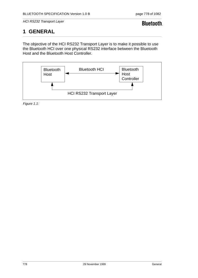
BLUETOOTH SPECIFICATION Version 1.0 B page 778 of 1082
HCI RS232 Transport Layer
1 GENERAL
The objective of the HCI RS232 Transport Layer is to make it possible to use the Bluetooth HCI over one physical RS232 interface between the Bluetooth Host and the Bluetooth Host Controller.
Figure 1.1:
BluetoothHost
BluetoothHostController
Bluetooth HCI
HCI RS232 Transport Layer
778 29 November 1999 General
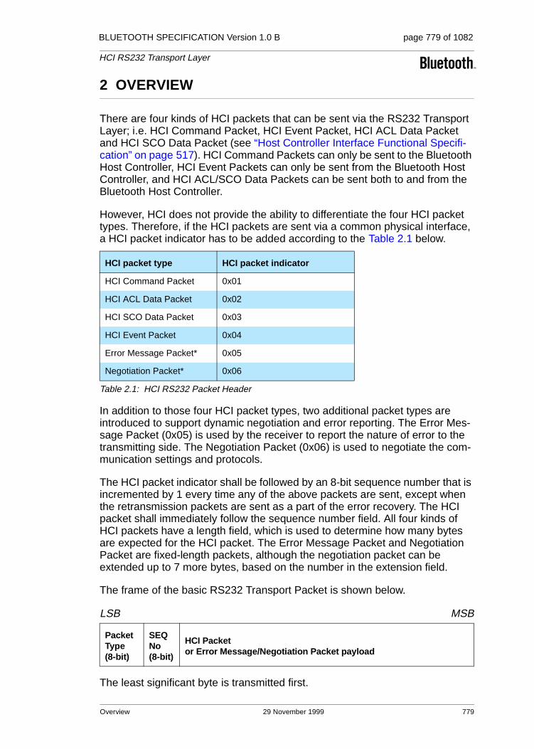
BLUETOOTH SPECIFICATION Version 1.0 B page 779 of 1082
HCI RS232 Transport Layer
2 OVERVIEW
There are four kinds of HCI packets that can be sent via the RS232 Transport Layer; i.e. HCI Command Packet, HCI Event Packet, HCI ACL Data Packet and HCI SCO Data Packet (see “Host Controller Interface Functional Specifi-cation” on page 517). HCI Command Packets can only be sent to the Bluetooth Host Controller, HCI Event Packets can only be sent from the Bluetooth Host Controller, and HCI ACL/SCO Data Packets can be sent both to and from the Bluetooth Host Controller.
However, HCI does not provide the ability to differentiate the four HCI packet types. Therefore, if the HCI packets are sent via a common physical interface, a HCI packet indicator has to be added according to the Table 2.1 below.
In addition to those four HCI packet types, two additional packet types are introduced to support dynamic negotiation and error reporting. The Error Mes-sage Packet (0x05) is used by the receiver to report the nature of error to the transmitting side. The Negotiation Packet (0x06) is used to negotiate the com-munication settings and protocols.
The HCI packet indicator shall be followed by an 8-bit sequence number that is incremented by 1 every time any of the above packets are sent, except when the retransmission packets are sent as a part of the error recovery. The HCI packet shall immediately follow the sequence number field. All four kinds of HCI packets have a length field, which is used to determine how many bytes are expected for the HCI packet. The Error Message Packet and Negotiation Packet are fixed-length packets, although the negotiation packet can be extended up to 7 more bytes, based on the number in the extension field.
The frame of the basic RS232 Transport Packet is shown below.
LSB MSB
The least significant byte is transmitted first.
HCI packet type HCI packet indicator
HCI Command Packet 0x01
HCI ACL Data Packet 0x02
HCI SCO Data Packet 0x03
HCI Event Packet 0x04
Error Message Packet* 0x05
Negotiation Packet* 0x06
Table 2.1: HCI RS232 Packet Header
Packet Type(8-bit)
SEQ No (8-bit)
HCI Packet or Error Message/Negotiation Packet payload
Overview 29 November 1999 779

BLUETOOTH SPECIFICATION Version 1.0 B page 780 of 1082
HCI RS232 Transport Layer
3 NEGOTIATION PROTOCOL
Before sending any bytes over the RS232 link, the baud rate, parity type, num-ber of stop bit and protocol mode should be negotiated between the Host Con-troller and the Host. Tdetect is the maximum time required for the transmitter to detect the CTS state change, plus the time it takes to flush the transmit buffer if RTS/CTS is used for error indication and re-synchronization. Otherwise, Tde-tect represents the local-side interrupt latency. Host will first send a negotiation packet with the maximum suggested values, plus Host’s Tdetect value with Ack code = 000b at the default UART settings specified below, using protocol mode = 0x13. At the same time, the Host Controller side also sets its UART settings to the same initiating parameters and waits for the negotiation packet from the Host. If the Host Controller side can accept the suggested values from the Host, it sends back the negotiation packet with the same UART setting values, plus Host Controller’s Tdetect value with Ack code = 001b. Then, the Host sends back the negotiation packet with the same UART setting values, plus Host’s Tdetect with Ack code = 001b as the final acknowledgment, and then sets its Host’s UART to the new value. After it has received the final acknowledgment packet from the Host, the Host Controller also changes its UART setting to the new values.
On the other hand, if the Host Controller side cannot accept the suggested value, it should send a set of new suggested values and its own Tdetect value with Ack code = 010b. Each side should continue these steps until both sides receive the accepted Ack code value. Error detection and error recovery during the initial negotiation are performed in the same manner as described in Sec-tion 5 on page 785 (Protocol Mode 0x13)
The negotiation phase can be initiated again by either side at any time in order to renegotiate the new values, or just to inform the new Tdetect time. When the negotiation is reinitiated during the data transfer, it should use the previously negotiated settings to exchange the new parameters rather than using the default values.
The initiating parameters:
baud rate: 9600 bps
parity type: no parity
number of data bit: 8 (Note: Only 8-bit data length is allowed.)
number of stop bit: 1
protocol mode: 0x13 (HDLC like framing with COBS/CCITT-CRC)
780 29 November 1999 Negotiation Protocol
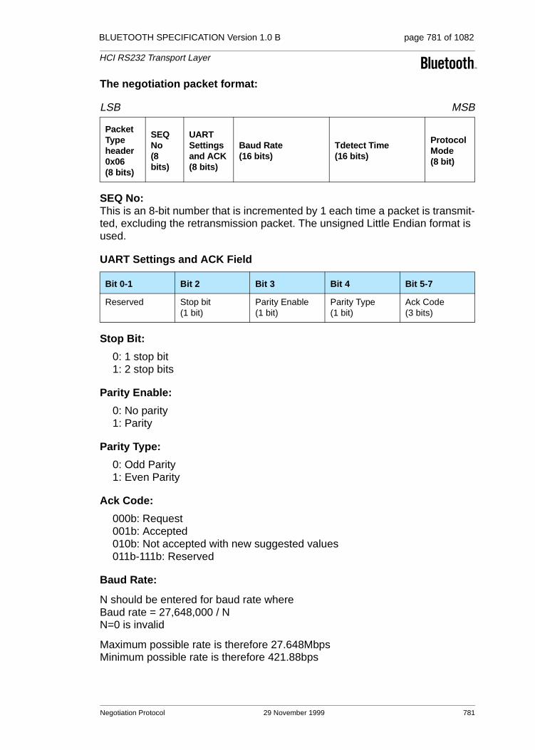
BLUETOOTH SPECIFICATION Version 1.0 B page 781 of 1082
HCI RS232 Transport Layer
The negotiation packet format:
LSB MSB
SEQ No:This is an 8-bit number that is incremented by 1 each time a packet is transmit-ted, excluding the retransmission packet. The unsigned Little Endian format is used.
UART Settings and ACK Field
Stop Bit:
0: 1 stop bit1: 2 stop bits
Parity Enable:
0: No parity1: Parity
Parity Type:
0: Odd Parity1: Even Parity
Ack Code:
000b: Request001b: Accepted010b: Not accepted with new suggested values011b-111b: Reserved
Baud Rate:
N should be entered for baud rate whereBaud rate = 27,648,000 / NN=0 is invalid
Maximum possible rate is therefore 27.648MbpsMinimum possible rate is therefore 421.88bps
Packet Type header 0x06 (8 bits)
SEQ No(8 bits)
UART Settingsand ACK(8 bits)
Baud Rate(16 bits)
Tdetect Time(16 bits)
Protocol Mode(8 bit)
Bit 0-1 Bit 2 Bit 3 Bit 4 Bit 5-7
Reserved Stop bit(1 bit)
Parity Enable(1 bit)
Parity Type(1 bit)
Ack Code(3 bits)
Negotiation Protocol 29 November 1999 781
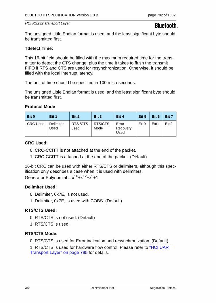
BLUETOOTH SPECIFICATION Version 1.0 B page 782 of 1082
HCI RS232 Transport Layer
The unsigned Little Endian format is used, and the least significant byte should be transmitted first.
Tdetect Time:
This 16-bit field should be filled with the maximum required time for the trans-mitter to detect the CTS change, plus the time it takes to flush the transmit FIFO if RTS and CTS are used for resynchronization. Otherwise, it should be filled with the local interrupt latency.
The unit of time should be specified in 100 microseconds.
The unsigned Little Endian format is used, and the least significant byte should be transmitted first.
Protocol Mode
CRC Used:
0: CRC-CCITT is not attached at the end of the packet.
1: CRC-CCITT is attached at the end of the packet. (Default)
16-bit CRC can be used with either RTS/CTS or delimiters, although this spec-ification only describes a case when it is used with delimiters. Generator Polynomial = x16+x12+x5+1
Delimiter Used:
0: Delimiter, 0x7E, is not used.
1: Delimiter, 0x7E, is used with COBS. (Default)
RTS/CTS Used:
0: RTS/CTS is not used. (Default)
1: RTS/CTS is used.
RTS/CTS Mode:
0: RTS/CTS is used for Error indication and resynchronization. (Default)
1: RTS/CTS is used for hardware flow control. Please refer to “HCI UART Transport Layer” on page 795 for details.
Bit 0 Bit 1 Bit 2 Bit 3 Bit 4 Bit 5 Bit 6 Bit 7
CRC Used Delimiter Used
RTS /CTS used
RTS/CTS Mode
Error Recovery Used
Ext0 Ext1 Ext2
782 29 November 1999 Negotiation Protocol

BLUETOOTH SPECIFICATION Version 1.0 B page 783 of 1082
HCI RS232 Transport Layer
Error Recovery Used:
0: Error Recovery is not supported.Even if Error Recovery is not supported, Error Message has to be sent.
1: Error Recovery is supported. (Default)Error Recovery retransmits the packet with error and all subsequentpackets if RTS/CTS are used for synchronization. On the other hand, if0x7E is used as a delimiter with COBS as a synchronization mechanism,then the error recovery retransmits only the packet with error. Pleaserefer to following sections for details.
Ext2,Ext1,Ext0:
These three bits indicate the number of extra bytes attached to the negotiation packet for future expansion.
Negotiation Protocol 29 November 1999 783

BLUETOOTH SPECIFICATION Version 1.0 B page 784 of 1082
HCI RS232 Transport Layer
4 PACKET TRANSFER PROTOCOL
The packet can be transferred with parity enabled or disabled, and with or with-out CRC – depending on the environment – as a mechanism to detect the error.
As a synchronization mechanism, one can select either RTS/CTS, or delimit-ers. Usage of RTS/CTS reduces the computation time for COBS encoding, but it requires two extra copper wires which may not be suitable in some applica-tions. If three-wire cable must be used, or programmable RTS and CTS are not available, delimiter, 0x7E, can be used with COBS.
However, error recovery for these two alternatives may differ slightly. If the RTS/CTS is used for resynchronization, it would be simpler to retransmit all the packets, starting with the packet that had an error. If delimiters are used, the transmitter should retransmit only the packet with an error. The error recovery can be disabled, but the error message packet should still be sent to the trans-mitter side when the receiver side detects an error.
The HCI RS232 transport layer always uses a data length of 8 bits, and this specification assumes the Little Endian format. Furthermore, the least signifi-cant byte should be transmitted first.
The Host Controller may choose to support only one protocol mode, but the Host should be able to support any combination.
Two common schemes (Protocol mode = 0x13 and 0x14) are defined in the fol-lowing sections to illustrate the usage of each mode.
784 29 November 1999 Packet Transfer Protocol
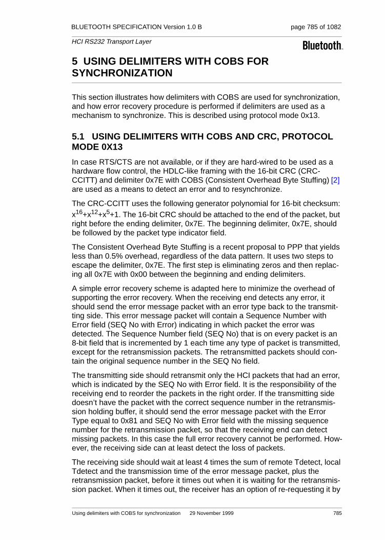
BLUETOOTH SPECIFICATION Version 1.0 B page 785 of 1082
HCI RS232 Transport Layer
5 USING DELIMITERS WITH COBS FOR SYNCHRONIZATION
This section illustrates how delimiters with COBS are used for synchronization, and how error recovery procedure is performed if delimiters are used as a mechanism to synchronize. This is described using protocol mode 0x13.
5.1 USING DELIMITERS WITH COBS AND CRC, PROTOCOL MODE 0X13
In case RTS/CTS are not available, or if they are hard-wired to be used as a hardware flow control, the HDLC-like framing with the 16-bit CRC (CRC-CCITT) and delimiter 0x7E with COBS (Consistent Overhead Byte Stuffing) [2] are used as a means to detect an error and to resynchronize.
The CRC-CCITT uses the following generator polynomial for 16-bit checksum: x16+x12+x5+1. The 16-bit CRC should be attached to the end of the packet, but right before the ending delimiter, 0x7E. The beginning delimiter, 0x7E, should be followed by the packet type indicator field.
The Consistent Overhead Byte Stuffing is a recent proposal to PPP that yields less than 0.5% overhead, regardless of the data pattern. It uses two steps to escape the delimiter, 0x7E. The first step is eliminating zeros and then replac-ing all 0x7E with 0x00 between the beginning and ending delimiters.
A simple error recovery scheme is adapted here to minimize the overhead of supporting the error recovery. When the receiving end detects any error, it should send the error message packet with an error type back to the transmit-ting side. This error message packet will contain a Sequence Number with Error field (SEQ No with Error) indicating in which packet the error was detected. The Sequence Number field (SEQ No) that is on every packet is an 8-bit field that is incremented by 1 each time any type of packet is transmitted, except for the retransmission packets. The retransmitted packets should con-tain the original sequence number in the SEQ No field.
The transmitting side should retransmit only the HCI packets that had an error, which is indicated by the SEQ No with Error field. It is the responsibility of the receiving end to reorder the packets in the right order. If the transmitting side doesn’t have the packet with the correct sequence number in the retransmis-sion holding buffer, it should send the error message packet with the Error Type equal to 0x81 and SEQ No with Error field with the missing sequence number for the retransmission packet, so that the receiving end can detect missing packets. In this case the full error recovery cannot be performed. How-ever, the receiving side can at least detect the loss of packets.
The receiving side should wait at least 4 times the sum of remote Tdetect, local Tdetect and the transmission time of the error message packet, plus the retransmission packet, before it times out when it is waiting for the retransmis-sion packet. When it times out, the receiver has an option of re-requesting it by
Using delimiters with COBS for synchronization 29 November 1999 785

BLUETOOTH SPECIFICATION Version 1.0 B page 786 of 1082
HCI RS232 Transport Layer
sending another error message packet with error type = 0x09, or simply drop-ping it and reporting it to the higher layer.
5.2 FRAME FORMAT
BOF(0x7E), CRC-CCITT, and EOF(0x7E) are added as shown below to those basic packets described in this document. When the CRC is transmitted, the least significant byte should be transmitted first.
LSB MSB
5.3 ERROR MESSAGE PACKET
The error-message packet format is the following:
LSB MSB
0x7E BOF(8 bits)
Packet Type(8 bits)
SEQ No (8 bits)
….Payload…. CRC(16 bits)
0x7E EOF(8 bits)
Packet Type, 0x05 (8-bit field)
Sequence No(8-bit field)
Error Type (8-bit field)
SEQ No with Error (8-bit field)
Error Type Description
0x00 Reserved
0x01 Overrun Error
0x02 Parity Error
0x03 Reserved
0x04 Framing Error
0x05-0x07 Reserved
0x08 CRC Error
0x09 Missing SEQ No
0x0A-0x80 Reserved
0x81 Missing Retransmission Packet
0x82- 0xFF Reserved
Table 5.1: Error Type available
786 29 November 1999Using delimiters with COBS for synchronization

BLUETOOTH SPECIFICATION Version 1.0 B page 787 of 1082
HCI RS232 Transport Layer
5.4 CONSISTENT OVERHEAD BYTE STUFFING
The COBS requires two step encodes.
The first step is the zero-elimination step. This step takes place after attaching the 16-bit CRC if CRC is enabled, but before adding the beginning and ending delimiters, 0x7E. Each COBS code block consists of the COBS code followed by zero or more data bytes. Code bytes 0x00, 0xD1, 0xD2 and 0xFF are never used. The COBS zero-elimination procedure searches the packet for the first occurrence of value zero. To simplify the encoding, a zero is added temporarily at the end of the packet, after the CRC, as a temporary place holder. The num-ber of octets up to and including the first zero determines the code to be used. If this number is 207 or less, then the number itself is used as a COBS code byte, followed by the actual non-zero data bytes themselves, excluding the last byte, which is zero. On the other hand, if the number is more than 207, then the code byte 0xD0 is used, followed by the first 207 non-zero bytes. This process is repeated until all of the bytes of the packet, including the temporary place-holding zero at the end, have been encoded. If a pair of 0x00 is detected after 0 to 30 non-zero octets, the count of octets plus 0xE0 is used as the COBS code, followed by the non-zero octets, excluding the pair of zeros. If a run of three to fifteen 0x00 octets are detected, then the count of these 0x00 octets, plus 0xD0, is used as the code, followed by no other bytes.
The second step is replacing 0x7E with 0x00. The two steps can be done together in a loop, to reduce the encoding time.
For more details and a reference code, please refer to “PPP Consistent Over-head Byte Stuffing (COBS)” by J. Carlson et al [2].
Code(n) Followed by Description
0x00 Unused.
0x01-0xCF n-1 data bytes The n-1 data bytes plus implicit trailing zero.
0xD0 n-1 data bytes The n-1 data bytes without trailing zero.
0XD1 Unused.
0xD2 Reserved for future.
0xD3-0xDF none A run of n-0xD0 zeros.
0xE0-0xFE n-E0 data bytes The data bytes with two trailing zeros.
0xFF Unused.
Table 5.2:
Using delimiters with COBS for synchronization 29 November 1999 787

BLUETOOTH SPECIFICATION Version 1.0 B page 788 of 1082
HCI RS232 Transport Layer
6 USING RTS/CTS FOR SYNCHRONIZATION
This section illustrates how RTS and CTS are used to resynchronize, and how error-recovery procedure is performed if RTS and CTS are used as a mecha-nism to synchronize. This is described using protocol mode 0x14.
6.1 USING RTS/CTS FOR SYNC WITHOUT CRC, PROTOCOL MODE 0X14
The flow of HCI packet transfer is handled by two MODEM control/status sig-nals, -RTS and -CTS. -RTS and -CTS are connected in a null MODEM fashion, meaning that the local-side -RTS should be connected to the remote-side -CTS, and the local-side -CTS should be connected to the remote-side -RTS. These MODEM control/status signals are used to notify the detection of an error to the other side, as well as to resynchronize the beginning of the packet after an error is detected. A very simple error-recovery scheme is adapted here to minimize the overhead of supporting this.
The HCI packet is transmitted only while CTS bit is 1. If the CTS bit changes to 0 during the HCI packet transfer or after the last byte is transmitted, this indi-cates that there was some error. The receiving end will deassert RTS as soon as it detects any error, and should send the error packet with an error type back to the transmission side. This error packet will contain a Sequence Number with Error field that indicates in which packet the error was detected. The sequence number field that is on every packet is an 8-bit field that is incre-mented by 1 each time any type of packet is transmitted, except for the retrans-mission packets. The retransmitted packets should contain the original sequence number in the SEQ No field.
When the transmitting end detects CTS bit changing from 1 to 0 at any time, the transmitting end should hold the transmission and wait until the error packet is received before resuming the transmission. When the receiving end is ready to receive the new data, it should assert RTS after the minimum of Tdetect time. Tdetect time is the maximum time required for the transmit side to detect the state change on CTS bit, plus the time it takes to flush the transmit buffer. The Tdetect value of each side should be informed to the other side dur-ing the negotiation phase. The local Tdetect value and the remote side Tdetect value together, along with the baud rate, can also be used to estimate the queue length required for the retransmission holding buffer. Before the receiv-ing side asserts RTS line again, it should flush the RX buffer.
The transmission side should retransmit all of the HCI packets from the packet that had an error, which is indicated by SEQ No with Error field. Before it retransmits, it should flush the transmit buffer that may hold the leftover data from the aborted previous packet. As it retransmits the packets from the retransmission holding buffer, it should start transmitting the packet with the Sequence Number that matches the SEQ No with Error. If the transmitting side doesn’t have the packet with the correct sequence number in the retransmis-sion holding buffer, the transmitter should send an error message packet with
788 29 November 1999 Using RTS/CTS for Synchronization

BLUETOOTH SPECIFICATION Version 1.0 B page 789 of 1082
HCI RS232 Transport Layer
error type 0x81, and it should skip to the packet with the sequence number that is available in the buffer. In this case, the full error recovery cannot be per-formed. However, the receiving side can, at least, detect the loss of packets.
6.2 ERROR MESSAGE PACKET
The error-message packet format is the following:
LSB MSB
Packet header 0x05 (8-bit field)
Sequence No (8-bit field)
Error Type (8-bit field)
SEQ No with Error (8-bit field)
Error Type Description Comment
0x00 Reserved
0x01 Overrun Error
0x02 Parity Error
0x03 Reserved
0x04 Framing Error
0x05-0x07 Reserved
0x08 CRC Error* Not applicable In Mode 0x14
0x09 Missing SEQ No
0x0A-0x80 Reserved
0x81 Missing Retransmission Packet
0x82- 0xFF Reserved
Table 6.1: Error Type available
Using RTS/CTS for Synchronization 29 November 1999 789

BLUETOOTH SPECIFICATION Version 1.0 B page 790 of 1082
HCI RS232 Transport Layer
6.3 EXAMPLE OF SIGNALLING
Byte with an error
Packet with Seq No= 5
RX Data of Host Side
-RTS of Host Side
TX Data of Host Controller Side
-CTS of H.C. Side
Packet with Seq No = 6 CTS change detected &TX aborted
H.C. side Tdetect
Retransmitted Packet with Seq No=5
Close to Host side Tdetect
Minimum Queue length –1 (packet length)
Error Packet
TX Data of Host Side RX Data of H.C .Side
-RTS of H.C. Side-CTS of Host Side
790 29 November 1999 Using RTS/CTS for Synchronization

BLUETOOTH SPECIFICATION Version 1.0 B page 791 of 1082
HCI RS232 Transport Layer
6.4 CONTROL FLOW EXAMPLES
6.4.1 Case 1, Normal Recovery Process
6.4.2 Case 2, Both sides detect an error simultaneously
Controller Side Host Side
0) RTS is asserted and the asserted CTS is detected.
0) RTS is asserted and the asserted CTS is detected.
1) Ctrl/Data[n] is sent out and Ctrl/Data[n] is stored in the retransmission holding buffer.
2) Ctrl/Data[n] is received with an error.
3) Deasserts RTS
4a) Error message for [n] is sent and Error message for [n] is stored in the TX retransmit holding buffer.
4b) Empties the RX FIFO and waits for Tdetect (Host) amount of time.
4) Detects CTS deasserted.
5a) Stops further transmission and waits until the TX FiFO is empty (or Flush the FIFO if it can.)
5b) Error message for [n] is received.
6) Asserts RTS
. 7) The asserted CTS is detected.
8) Retransmits Ctrl/Data[n].
Controller Side Host Side
0) RTS is asserted and the asserted CTS is detected.
0) RTS is asserted and the asserted CTS is detected.
1) Ctrl/Data[x] is sent and Ctrl/Data[x] is stored in the retransmission holding buffer.
1) Ctrl/Data[n] is sent and Ctrl/Data[n] is stored in the retransmission holding buffer.
2) Ctrl/Data[n] is received with an error. 2) Ctrl/Data[x] is received with an error.
3) Deasserts RTS. 3) Deasserts RTS.
4) Detects CTS deasserted. 4) Detects CTS deasserted.
5a) Stops further transmission and waits until the TX FiFO is empty (or Flush the FIFO if it can).
5a) Stops further transmission and waits until the TX FiFO is empty (or Flush the FIFO if it can).
Using RTS/CTS for Synchronization 29 November 1999 791

BLUETOOTH SPECIFICATION Version 1.0 B page 792 of 1082
HCI RS232 Transport Layer
6.4.3 Case 3, Error Message with an error
5b) Empties the RX FIFO and waits for Tde-tect (Host) amount of time.
5b) Empties the RX FIFO and waits for Tdetect (Controller) amount of time.
6) Asserts RTS. 6) Asserts RTS.
7) The asserted CTS is detected. 7) The asserted CTS is detected.
8) Error message for [n] is sent and Error message for [n] is stored in the TX retransmit holding buffer.
8) Error message for [x] is sent and Error message for [x] is stored in the TX retransmit holding buffer.
9) Error message for [x] is received. 9) Error message for [n] is received.
10) Retransmits Ctrl/Data[x]. 10) Retransmits Ctrl/Data[n].
Controller Side Host Side
0) RTS is asserted and the asserted CTS is detected.
0) RTS is asserted and the asserted CTS is detected.
1) Ctrl/Data[n] is sent and Ctrl/Data[n] is stored in the retransmission holding buffer.
2) Ctrl/Data[n] is received with an error.
3) Deasserts RTS.
4a) Error message for [n] (Err[n]) is sent and Err[n] is stored in the TX retransmit hold-ing buffer.
4b) Empties the RX FIFO and waits for Tde-tect (Host) amount of time.
4) Detects CTS deasserted.
5a) Stops further transmission and waits until the TX FiFO is empty (or Flush the FIFO if it can.)
5b) Error message for [n] is received with an error.
6) Asserts RTS. 6a) Deasserts RTS.
6b) Empties the RX FIFO and waits for Tde-tect (Controller) amount of time.
7) Detects CTS deasserted.
8) Stops further transmission and waits until the TX FiFO is empty (or Flush the FIFO if it can.)
8) The asserted CTS detected.
Controller Side Host Side
792 29 November 1999 Using RTS/CTS for Synchronization

BLUETOOTH SPECIFICATION Version 1.0 B page 793 of 1082
HCI RS232 Transport Layer
9a) Error message for Err[n] is sent and Error message for Err[n] is stored in the retransmission holding buffer.
9b) Asserts RTS.
10a) Error message for Err[n] is received.
10b) The asserted CTS detected.
11) Retransmits Error message for [n].
12) Error message for [n] is received.
13) Retransmit Ctrl/Data[n].
Controller Side Host Side
Using RTS/CTS for Synchronization 29 November 1999 793

BLUETOOTH SPECIFICATION Version 1.0 B page 794 of 1082
HCI RS232 Transport Layer
7 REFERENCES
[1] Bluetooth Host Controller Interface Function Specification
[2] J. Carlson, S. Cheshire, M. Baker, draft-ietf-pppext-cobs-00, “PPP Consistent Overhead Byte Stuffing (COBS)”, November, 1997
[3] Bluetooth HCI UART Transport Layer Specification
794 29 November 1999 References

Part H:4
HCI UART TRANSPORT LAYER
An addendum to the HCI document
This document describes the UART transport layer (between the Host and the Host Controller). HCI command, event and data packets flow through this layer, but the layer does not decode them.

BLUETOOTH SPECIFICATION Version 1.0 B page 796 of 1082
HCI UART Transport Layer
796 29 November 1999

BLUETOOTH SPECIFICATION Version 1.0 B page 797 of 1082
HCI UART Transport Layer
CONTENTS
1 General ..............................................................................................798
2 Protocol.............................................................................................799
3 RS232 Settings .................................................................................800
4 Error Recovery .................................................................................801
29 November 1999 797

BLUETOOTH SPECIFICATION Version 1.0 B page 798 of 1082
HCI UART Transport Layer
1 GENERAL
The objective of this HCI UART Transport Layer is to make it possible to use the Bluetooth HCI over a serial interface between two UARTs on the same PCB. The HCI UART Transport Layer assumes that the UART communication is free from line errors. See also “HCI RS232 Transport Layer” on page 775.
BluetoothHost
BluetoothHostController
Bluetooth HCI
HCI UART Transport Layer
798 29 November 1999 General

BLUETOOTH SPECIFICATION Version 1.0 B page 799 of 1082
HCI UART Transport Layer
2 PROTOCOL
There are four kinds of HCI packets that can be sent via the UART Transport Layer; i.e. HCI Command Packet, HCI Event Packet, HCI ACL Data Packet and HCI SCO Data Packet (see “Host Controller Interface Functional Specifi-cation” on page 517). HCI Command Packets can only be sent to the Bluetooth Host Controller, HCI Event Packets can only be sent from the Bluetooth Host Controller, and HCI ACL/SCO Data Packets can be sent both to and from the Bluetooth Host Controller.
HCI does not provide the ability to differentiate the four HCI packet types. Therefore, if the HCI packets are sent via a common physical interface, a HCI packet indicator has to be added according to Table 2.11 below.
The HCI packet indicator shall be sent immediately before the HCI packet. All four kinds of HCI packets have a length field, which is used to determine how many bytes are expected for the HCI packet. When an entire HCI packet has been received, the next HCI packet indicator is expected for the next HCI packet. Over the UART Transport Layer, only HCI packet indicators followed by HCI packets are allowed.
HCI packet type HCI packet indicator
HCI Command Packet 0x01
HCI ACL Data Packet 0x02
HCI SCO Data Packet 0x03
HCI Event Packet 0x04
Table 2.1: HCI packet indicators
Protocol 29 November 1999 799
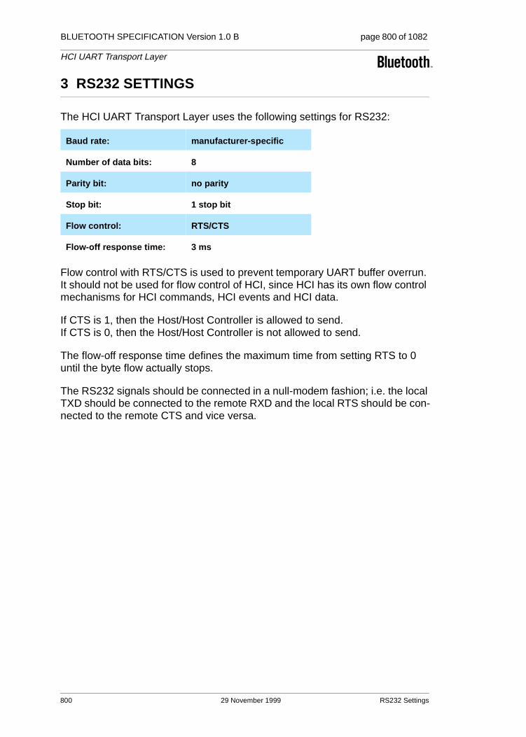
BLUETOOTH SPECIFICATION Version 1.0 B page 800 of 1082
HCI UART Transport Layer
3 RS232 SETTINGS
The HCI UART Transport Layer uses the following settings for RS232:
Flow control with RTS/CTS is used to prevent temporary UART buffer overrun. It should not be used for flow control of HCI, since HCI has its own flow control mechanisms for HCI commands, HCI events and HCI data.
If CTS is 1, then the Host/Host Controller is allowed to send. If CTS is 0, then the Host/Host Controller is not allowed to send.
The flow-off response time defines the maximum time from setting RTS to 0 until the byte flow actually stops.
The RS232 signals should be connected in a null-modem fashion; i.e. the local TXD should be connected to the remote RXD and the local RTS should be con-nected to the remote CTS and vice versa.
Baud rate: manufacturer-specific
Number of data bits: 8
Parity bit: no parity
Stop bit: 1 stop bit
Flow control: RTS/CTS
Flow-off response time: 3 ms
800 29 November 1999 RS232 Settings

BLUETOOTH SPECIFICATION Version 1.0 B page 801 of 1082
HCI UART Transport Layer
4 ERROR RECOVERY
If the Host or the Host Controller lose synchronization in the communication over RS232, then a reset is needed. A loss of synchronization means that an incorrect HCI packet indicator has been detected, or that the length field in an HCI packet is out of range.
If the UART synchronization is lost in the communication from Host to Host Controller, then the Host Controller shall send a Hardware Error Event to tell the Host about the synchronization error. The Host Controller will then expect to receive an HCI_Reset command from the Host in order to perform a reset. The Host Controller will also use the HCI_Reset command in the byte stream from Host to Host Controller to re-synchronize.
If the UART synchronization is lost in the communication from Host Controller to Host, then the Host shall send the HCI_Reset command in order to reset the Host Controller. The Host shall then re-synchronize by looking for the HCI Command Complete event for the HCI_Reset command in the byte stream from Host Controller to Host.
See “Host Controller Interface Functional Specification” on page 517 for HCI commands and HCI events.
Error Recovery 29 November 1999 801

BLUETOOTH SPECIFICATION Version 1.0 B page 802 of 1082
HCI UART Transport Layer
802 29 November 1999 Error Recovery
Part I:1
BLUETOOTH TEST MODE
This document describes the test mode for hardware and low-level functionality tests of Bluetooth devices. The test mode includes transmitter tests (packets with constant bit patterns) and loop back tests.


BLUETOOTH SPECIFICATION Version 1.0 B page 805 of 1082
Bluetooth Test Mode
CONTENTS
1 General Description .........................................................................8061.1 Test Setup ................................................................................8061.2 Activation .................................................................................8071.3 Control .....................................................................................807
2 Test Scenarios..................................................................................8082.1 Transmitter Test .......................................................................808
2.1.1 Packet Format .............................................................808
2.1.2 Pseudorandom Sequence...........................................810
2.1.3 Reduced Hopping Sequence ......................................811
2.1.4 Control of Transmit Parameters ..................................811
2.1.5 Power Control..............................................................812
2.1.6 Switch between different Frequency Settings .............812
2.2 LoopBack Test .........................................................................812
3 Outline of Proposed LMP Messages ..............................................817
4 References........................................................................................819
29 November 1999 805

BLUETOOTH SPECIFICATION Version 1.0 B page 806 of 1082
Bluetooth Test Mode
1 GENERAL DESCRIPTION
The test mode supports testing of the Bluetooth transmitter and receiver. It is intended mainly for certification/compliance testing of the radio and baseband layer, and may also be used for regulatory approval or in-production and after-sales testing.
A device in test mode must not support normal operation. For security reasons the test mode is designed such that it offers no benefit to the user. Therefore, no data output or acceptance on a HW or SW interface is allowed.
1.1 TEST SETUP
The setup consists of a device under test (DUT) and a tester. Optionally, addi-tional measurement equipment may be used.
Figure 1.1: Setup for Test Mode
Tester and DUT form a piconet where the tester acts as master and has full control over the test procedure. The DUT acts as slave.
The control is done via the air interface using LMP commands (see Section 3 on page 817 and “Link Manager Protocol” on page 185). Hardware interfaces to the DUT may exist, but are not subject to standardization.
The test mode is a special state of the Bluetooth model. For security and type approval reasons, a device in test mode may not support normal operation. When the DUT leaves the test mode it enters the standby state. After power-off the Bluetooth device must return to standby state.
Tester
AdditionalMeasurement
Equipment(optional)
Device under Test
Control commands
Test data
Local activation/enabling
806 29 November 1999 General Description

BLUETOOTH SPECIFICATION Version 1.0 B page 807 of 1082
Bluetooth Test Mode
1.2 ACTIVATION
The activation may be carried out locally (via a HW or SW interface), or using the air interface.
• For activation over the air interface, entering the test mode must be locally enabled for security and type approval reasons. The implementation of this local enabling is not subject to standardization.
The tester sends an LMP command that forces the DUT to enter test mode. The DUT terminates all normal operation before entering the test mode.
The DUT shall return an LMP_Accepted on reception of an activation com-mand. LMP_Not_Accepted shall be returned if the DUT is not locally enabled.
• If the activation is performed locally using a HW or SW interface, the DUT terminates all normal operation before entering the test mode.
Until a connection to the tester exists, the device shall perform page scan and inquiry scan. Extended scan activity is recommended.
1.3 CONTROL
Control and configuration is performed using special LMP commands (see Section 3 on page 817). These commands must be rejected if the Bluetooth device is not in test mode. In this case, an LMP_not_accepted is returned. The DUT shall return an LMP_accepted on reception of a control command when in test mode.
A Bluetooth device in test mode must ignore all LMP commands not related to control of the test mode. LMP commands dealing with power control and the request for LMP features (LMP_features_req) are allowed in test mode; the normal procedures are also used to test the adaptive power control.
The DUT can be commanded to leave the test mode by an LMP_Detach com-mand or by sending an LMP_test_control command with test scenario set to ’exit test mode’.
General Description 29 November 1999 807
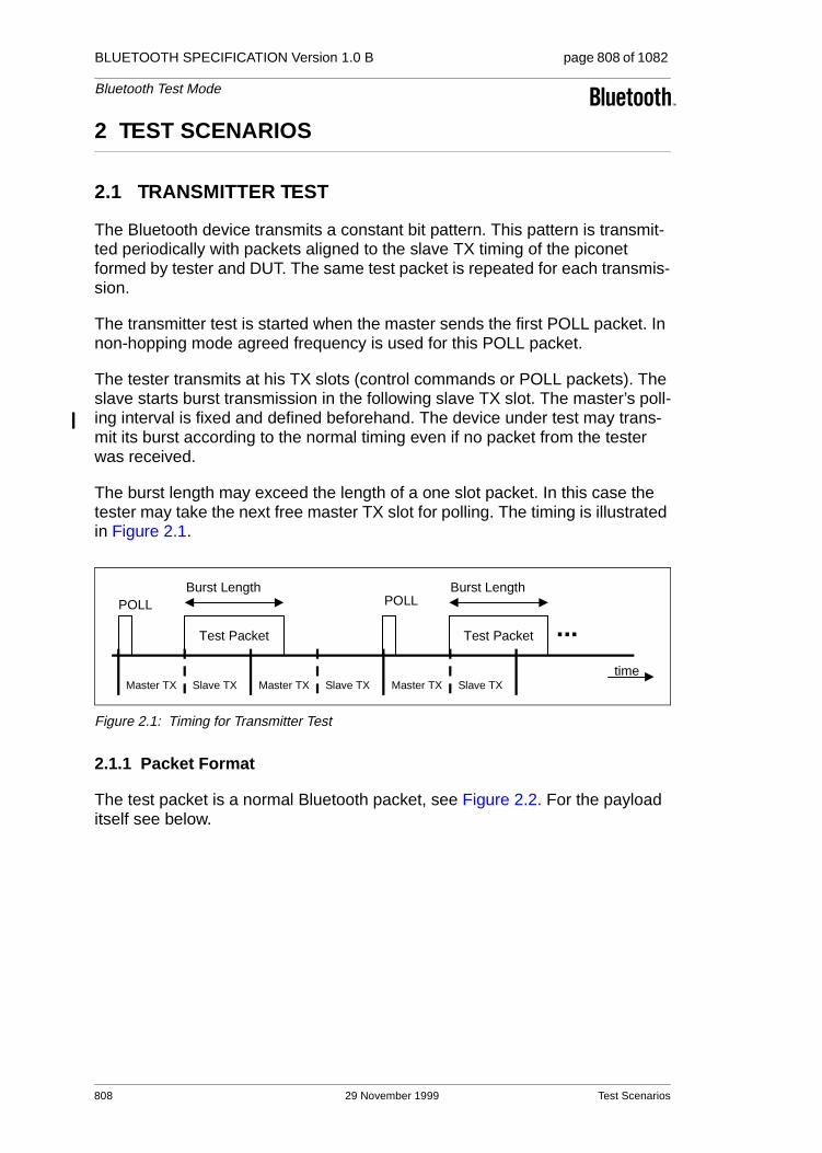
BLUETOOTH SPECIFICATION Version 1.0 B page 808 of 1082
Bluetooth Test Mode
2 TEST SCENARIOS
2.1 TRANSMITTER TEST
The Bluetooth device transmits a constant bit pattern. This pattern is transmit-ted periodically with packets aligned to the slave TX timing of the piconet formed by tester and DUT. The same test packet is repeated for each transmis-sion.
The transmitter test is started when the master sends the first POLL packet. In non-hopping mode agreed frequency is used for this POLL packet.
The tester transmits at his TX slots (control commands or POLL packets). The slave starts burst transmission in the following slave TX slot. The master’s poll-ing interval is fixed and defined beforehand. The device under test may trans-mit its burst according to the normal timing even if no packet from the tester was received.
The burst length may exceed the length of a one slot packet. In this case the tester may take the next free master TX slot for polling. The timing is illustrated in Figure 2.1.
Figure 2.1: Timing for Transmitter Test
2.1.1 Packet Format
The test packet is a normal Bluetooth packet, see Figure 2.2. For the payload itself see below.
Test Packet
Burst Length
...POLL POLL
Test Packet
Burst Length
timeMaster TX Slave TX Master TX Slave TX Master TX Slave TX
808 29 November 1999 Test Scenarios

BLUETOOTH SPECIFICATION Version 1.0 B page 809 of 1082
Bluetooth Test Mode
Figure 2.2: General Format of TX Packet
During configuration the tester defines:
• the packet type to be used
• payload length
For the payload length, the restrictions from the baseband specification apply (see “Baseband Specification” on page 33.). In case of ACL packets the pay-load structure defined in the baseband specification is preserved as well, see Figure 2.2.
For the transmitter test mode, only packets without FEC should be used; i.e. HV3, DH1, DH3, DH5and AUX1packets. Support of packet type is only manda-tory up to the longest implemented packet type.
In transmitter test mode, the packets exchanged between tester and DUT are not scrambled with the whitening sequence. Whitening is turned off when the DUT has accepted to enter the transmitter test mode, and is turned on when the DUT has accepted to exit the transmitter test mode, see Figure 2.3.1
1. Note: Implementations must ensure that retransmissions of the LMP_Accepted messages use the same whitening status.
Access Code Packet Header Payload
Test PatternPayloadHeader CRC
Test Pattern
ACL Packet(with CRC)
SCO Packet
Test PatternPayloadHeader
AUX1 Packet
Test Scenarios 29 November 1999 809

BLUETOOTH SPECIFICATION Version 1.0 B page 810 of 1082
Bluetooth Test Mode
Figure 2.3: Use of whitening in Transmitter mode
2.1.2 Pseudorandom Sequence
In case of pseudorandom bit sequence, the same sequence of bits is used for each transmission (i.e. the packet is repeated, see above). A PRBS-9 Sequence2 is used, see [2] and [3].
The properties of this sequence are as follows (see [3]). The sequence may be generated in a nine-stage shift register whose 5th and 9th stage outputs are added in a modulo-two addition stage (see Figure 2.4), and the result is fed back to the input of the first stage. The sequence begins with the first ONE of 9 consecutive ONEs; i.e. the shift register is initialized with nine ones.
• Number of shift register stages: 9
• Length of pseudo-random sequence: 29-1 = 511 bits
• Longest sequence of zeros: 8 (non-inverted signal)
Figure 2.4: Linear Feedback Shift Register for Generation of the PRBS sequence
2. Some uncertainties about Japanese regulatory requirements have been reported. If neces-sary for regulatory type approval in Japan, some features might be added; e.g. a longer PN sequence.
TESTER DUT
LMP_test_control(Enter Transmitter Test
d )LMP_accepted Whitening on
LMP_test_control(Exit Transmitter Test
d )LMP_accepted
Whitening off
Whitening on
+
810 29 November 1999 Test Scenarios

BLUETOOTH SPECIFICATION Version 1.0 B page 811 of 1082
Bluetooth Test Mode
2.1.3 Reduced Hopping Sequence
To support quick testing of the radio over the complete frequency range, a reduced hopping mode is defined. Implementation of this mode is optional for Bluetooth devices and modules.
Reduced hopping uses only five frequencies, on which a sequential hopping is done (channels 0, 23, 46, 69 and 93 are used3), see Figure 2.5.
Figure 2.5: Reduced hopping scheme
The timing is based on the Bluetooth clock of the tester. The value of CLK27-1 (i.e. not using CLK0, representing half slots) modulo 5 is used to determine the transmit frequency.
2.1.4 Control of Transmit Parameters
The following parameters can be set to configure the transmitter test:
1. Bit pattern:• Constant zero• Constant one• Alternating 1010...4
• Alternating 1111 0000 1111 0000...4
• Pseudorandom bit pattern• Transmission off
2. Frequency selection:• Single frequency • Hopping Europe/USA• Hopping Japan• Hopping France• Hopping Spain• Reduced Hopping (implementation in Bluetooth devices and modules is optional)
3. TX frequency • k ⇒ f := (2402 + k) MHz
3. The range is chosen to test the whole frequency range, which covers the normal 79 channels, as well as Spanish, French and Japanese hopping schemes. The frequency assignment rule is the same as for the fixed TX frequency: f = (2402 + k) MHz.
4. It is recommended that the sequence starts with a one; but, as this is irrelevant for measure-ments, it is also allowed to start with a zero.
0 23 46 69 93
CLK27-1 mod 5 = 0 1 2 3 4
Channel
Test Scenarios 29 November 1999 811

BLUETOOTH SPECIFICATION Version 1.0 B page 812 of 1082
Bluetooth Test Mode
4. Default poll period in TDD frames (n * 1.25 ms)
5. Packet Type
6. Length of Test Sequence (user data of packet definition in Baseband Speci-fication” on page 33.)
2.1.5 Power Control
If adaptive power control is tested, the normal LMP commands will be used. The DUT starts to transmit at the maximum power and reduces/increases its power by one step on every command received.
2.1.6 Switch between different Frequency Settings
A change in the frequency selection becomes effective when the LMP proce-dure is completed:
The tester switches to a new frequency or hopping pattern after the LMP_Accepted message has been received.
The DUT switches after the LMP_accepted message has been sent.
Note: Loss of the LMP_Accepted packet will eventually lead to a loss of frequency synchronization that cannot be recovered. Similar problems occur in normal operation, when the hopping pattern changes.
2.2 LOOPBACK TEST
The device under test receives normal baseband packets. The received pack-ets are decoded in the DUT, and the payload is sent back using the same packet type. The return packet is sent back in either the TX slot directly follow-ing the transmission of the tester, or it is delayed and sent back in the slot after the next transmission of the tester (see Figure 2.7 to Figure 2.9 on page 815).
Alternatively, it is possible to implement a delayed loopback instead. Then the return packet is delayed to the following TX slot. There is no signalling to deter-mine or control the mode. The device behavior must be fixed or adjusted by other means, but must not change randomly.
The tester can select, whether whitening is on or off. This setting holds for both up- and downlink. For switching the whitening status, the same rules as in Sec-tion 2.1 on page 808 (Figure 2.3) apply.
The following rules apply (for illustration see Figure 2.6 on page 814):
• Clearly, if the synch word was not detected, there will be no reply.
• If the header error check (HEC) fails, the DUT replies with a NULL packet with the ARQN bit set to NAK. It is not mandatory to return a NULL packet in this case; the DUT may send nothing.
812 29 November 1999 Test Scenarios
BLUETOOTH SPECIFICATION Version 1.0 B page 813 of 1082
Bluetooth Test Mode
• If the packet contains an LMP message relating to the control of the test mode this command is executed and the packet is not returned, though ACK or NAK is still returned as usual procedure. Other LMP commands are ignored and no packet is returned.
• The payload FEC is decoded and the payload is coded again for transmis-sion. This allows testing of the FEC handling. If the pure bit error rate shall be determined the tester chooses a packet type without FEC.
• The CRC is evaluated. In case of a failure, the payload is returned with ARQN = NAK. The CRC for the return packet is calculated for the returned payload.
• If the CRC fails the number of bytes as indicated in the (possibly erroneous) payload header shall be looped back.
Test Scenarios 29 November 1999 813
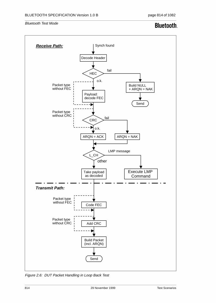
BLUETOOTH SPECIFICATION Version 1.0 B page 814 of 1082
Bluetooth Test Mode
Figure 2.6: DUT Packet Handling in Loop Back Test
Take payloadas decoded
Code FEC
Add CRC
Send
Packet typewithout FEC
Packet typewithout CRC
Decode Header
Synch found
HEC
Build NULL+ ARQN = NAK
Payload: decode FEC
CRC
Packet typewithout FEC
ARQN = ACK ARQN = NAK
Send
Packet typewithout CRC
fail
fail
o.k.
o.k.
L_CHLMP message
other
Execute LMP Command
Build Packet(incl. ARQN)
Transmit Path:
Receive Path:
814 29 November 1999 Test Scenarios

BLUETOOTH SPECIFICATION Version 1.0 B page 815 of 1082
Bluetooth Test Mode
The timing for normal and delayed loopback is illustrated in Figure 2.7 to Figure 2.9:
Figure 2.7: Payload & ARQN handling in normal loopback.
Figure 2.8: Payload & ARQN handling in delayed loopback - start.
Figure 2.9: Payload & ARQN handling in delayed loopback - end.
The whitening is performed in the same way as it is used in normal active mode.
The following parameters can be set to configure the loop back test:
1. Packet Class5
• ACL Packets• SCO Packets• ACL Packets without whitening• SCO Packets without whitening
5. This is included because, in the future, the packet type numbering may not remain unambiguous.
RX Packet
Master TX Slave TX
TX Packet RX Packet
Master TX Slave TX
TX Packet RX Packet
Master TX Slave TX
TX Packet
Payload Payload Payload
time
ARQN ARQN ARQN
RX Packet
Master TX Slave TXA
CK RX Packet
Master TX Slave TX
TX Packet RX Packet
Master TX Slave TX
TX Packet
Payload Payload
time
ARQN ARQN ARQN
Payload
RX Packet
Master TX Slave TX
PollRX Packet
Master TX Slave TX
TX Packet
Master TX Slave TX
TX Packet
Payload Payload
time
ARQN ARQN ARQN
Payload
TX Packet
Test Scenarios 29 November 1999 815

BLUETOOTH SPECIFICATION Version 1.0 B page 816 of 1082
Bluetooth Test Mode
2. Frequency Selection• Single frequency (independent for RX and TX)• Hopping Europe/USA• Hopping Japan• Hopping France• Hopping Spain • Hopping reduced (optional)
Hopping reduced uses only five frequencies on which a sequential hopping is done on (channel: 0, 23, 46, 69 and 93 is used).
3. Power level: (To be used according radio specification requirements)• power control or fixed TX power
The switch of the frequency setting is done exactly as for the transmitter test (see Section 2.1.6 on page 812).
816 29 November 1999 Test Scenarios

BLUETOOTH SPECIFICATION Version 1.0 B page 817 of 1082
Bluetooth Test Mode
3 OUTLINE OF PROPOSED LMP MESSAGES
Table 3.1 lists all LMP messages used for test mode (see Link Manager Proto-col, Section 6 on page 237).
LMP PDUPDUnumber
PossibleDirection Contents
Positionin Payload
LMP_test_activate 56 m → s
LMP_test_control 57 m → s test scenariohopping modeTX frequencyRX frequencypower control modepoll period packet typelength of test data
23456789-10
LMP_detach 7 m → s
LMP_accepted 3 m ← s
LMP_not_accepted 4 m ← s
Table 3.1: LMP messages used for Test Mode
Name Length(bytes)
Type Unit Detailed
Test scenario 1 u_int8 0 Pause (TX off)1 Transmitter test – 0 pattern2 Transmitter test – 1 pattern3 Transmitter test – 1010 pattern4 Pseudorandom bit sequence5 Closed Loop Back – ACL packets6 Closed Loop Back – SCO packets7 ACL Packets without whitening8 SCO Packets without whitening9 Transmitter test – 1111 0000 pattern10–254 reserved255 Exit Test Mode
Hopping mode 1 u_int8 0 RX/TX on single frequency1 Hopping Europe/USA2 Hopping Japan3 Hopping France4 Hopping Spain5 Reduced Hopping (optional)
6–255 reserved
TX frequency (for DUT) 1 u_int8 f = [2402 + k] MHz
Table 3.2: Parameters used in LMP_Test_Control PDU
Outline of Proposed LMP Messages 29 November 1999 817

BLUETOOTH SPECIFICATION Version 1.0 B page 818 of 1082
Bluetooth Test Mode
The control PDU is used for both transmitter and loop back tests. The following restrictions apply for the parameter settings:
RX frequency (for DUT) 1 u_int8 f = [2402 + k] MHz
Power control mode 1 u_int8 0 fixed TX output power1 adaptive power control
Poll period 1 u_int8 1.25 ms
Packet type 1 u_int8 numbering as in packet header, see Baseband Specification)
length of test sequence (=length of user data in Baseband Specifica-tion)
2 u_int16 1 byte unsigned binary number
Parameter RestrictionsTransmitter Test
RestrictionsLoopback Test
TX frequency 0 ≤ k ≤ 93 0 ≤ k ≤ 93
RX frequency same as TX frequency 0 ≤ k ≤ 93
Poll period not applicable (set to 0)
Length of test sequence depends on packet type:
DH1: ≤ 28 byte
DH3: ≤ 181 byte
DH5: ≤ 339 byte
AUX1: ≤ 29 Byte
HV3: = 30 byte
not applicable (set to 0)
Table 3.3: Restrictions for Parameters used in LMP_Test_Control PDU
Name Length(bytes)
Type Unit Detailed
Table 3.2: Parameters used in LMP_Test_Control PDU
818 29 November 1999 Outline of Proposed LMP Messages

BLUETOOTH SPECIFICATION Version 1.0 B page 819 of 1082
Bluetooth Test Mode
4 REFERENCES
[1] Bluetooth Link Manager Protocol.
[2] CCITT Recommendation O.153 (1992), Basic parameters for the mea-surement of error performance at bit rates below the primary rate.
[3] ITU-T Recommendation O.150 (1996), General requirements for instru-mentation for performance measurements on digital transmission equip-ment.
[4] Bluetooth Baseband Specification.
References 29 November 1999 819

BLUETOOTH SPECIFICATION Version 1.0 B page 820 of 1082
Bluetooth Test Mode
820 29 November 1999 References

Part I:2
BLUETOOTH COMPLIANCE REQUIREMENTS
This document specifies the requirements for Bluetooth compliance.

BLUETOOTH SPECIFICATION Version 1.0 B page 822 of 1082
Bluetooth Compliance Requirements
822 29 November 1999
BLUETOOTH SPECIFICATION Version 1.0 B page 823 of 1082
Bluetooth Compliance Requirements
CONTENTS
1 Scope ................................................................................................825
2 Terms used .......................................................................................826
3 Legal aspects ...................................................................................828
4 The value of the Bluetooth Brand...................................................829
5 The Bluetooth qualification program .............................................830
6 Bluetooth license requirements for products ...............................8326.1 Bluetooth radio link requirements.............................................832
6.1.1 Requirement description .............................................8326.1.2 Qualification.................................................................832
6.2 Bluetooth protocol requirements ..............................................8326.2.1 Qualification.................................................................833
6.3 Bluetooth profile requirements .................................................8336.3.1 Requirement description .............................................8336.3.2 Qualification.................................................................834
6.4 Bluetooth information requirements .........................................8346.4.1 Requirement description .............................................8346.4.2 Qualification.................................................................834
6.5 Requirements on Bluetooth accessory products......................8346.5.1 Definition of ‘Bluetooth accessory products’................8346.5.2 Qualification.................................................................834
6.6 Requirements on Bluetooth components .................................8346.6.1 Definition of “Bluetooth components” ..........................8346.6.2 Requirement description .............................................8356.6.3 Qualification.................................................................835
7 Bluetooth license provisions for early products...........................836
29 November 1999 823

BLUETOOTH SPECIFICATION Version 1.0 B page 824 of 1082
Bluetooth Compliance Requirements
8 Bluetooth Brand License provisions for special products & marketing..........................................................................................8378.1 Bluetooth Development tools and demos ................................837
8.1.1 Definition of ‘Bluetooth Development tools and demos’ .................................................................837
8.1.2 Requirement description .............................................8378.1.3 Qualification ................................................................837
8.2 Marketing .................................................................................837
9 Recommendations concerning information about a product’s Bluetooth capabilities......................................................................838
10 Quality management, configuration management and version control...............................................................................................839
11 Appendix A – Example of a “Bluetooth Capability Statement” ...840
12 Appendix B - Marketing names of Bluetooth profiles ..................841
824 29 November 1999

BLUETOOTH SPECIFICATION Version 1.0 B page 825 of 1082
Bluetooth Compliance Requirements
1 SCOPE
The Bluetooth Promoters and the Bluetooth Adopters have signed the Promot-ers’ Agreement and the Adopters’ Agreement respectively. These agreements grant Promoters and Adopters a Bluetooth license for “products which comply with the Specification”.
This document specifies the requirements which must be met by a Promoter or Adopter to demonstrate that a particular product does “comply with the Specifi-cation”, thereby qualifying that particular product to be subject to the rights extended by the Promoters’ and Adopters’ Agreements respectively.
The Bluetooth Qualification Program is the process by which a Promoter or an Adopter demonstrates that a particular product meets the requirements speci-fied herein. This document provides an overview of the requirements and the Bluetooth Qualification Program. Further details are available through the Bluetooth Web site.
Regulatory requirements and governmental type approval requirements are outside the scope of this document.
Scope 29 November 1999 825

BLUETOOTH SPECIFICATION Version 1.0 B page 826 of 1082
Bluetooth Compliance Requirements
2 TERMS USED
Bluetooth Trademark – As defined in the Promoters’ Agreement and the Adopters’ Agreement.
Bluetooth Brand – Covers all the brand elements specified in the “The Blue-tooth Brand Book”. Equal to the Bluetooth Trademark.
Bluetooth Logo or Logo – the brand element referred to as the ‘figure mark’ in the ‘The Bluetooth Brand Book’.
Bluetooth License – all the rights, defined in the Promoters’ and Adopters’ Agreements respectively, that are granted by compliance with the specification, i.e. the Bluetooth Patent License and the Bluetooth Brand License.
Bluetooth Patent License – the applicable parts of the Bluetooth license con-sisting of patent rights or parts thereof as defined in the Promoters’ and Adopters’ Agreements respectively.
Bluetooth Brand License – the applicable parts of the Bluetooth license con-sisting of trademark rights as defined in the Promoters’ and Adopters’ Agree-ments respectively.
Protocol specification – defines the communication between two peer devices at a certain layer.
Profile specification – defines the usage of (parts of) the protocol stack for a certain Bluetooth usage model.
Bluetooth qualification process – the rules and procedures by which the manu-facturer demonstrates compliance to the Bluetooth specification.
Bluetooth qualification program – the implementation of the Bluetooth qualifica-tion process.
Bluetooth Qualification Review Board (BQRB) – responsible for managing, reviewing and improving the Bluetooth qualification program. The original Bluetooth SIG companies will appoint BQRB initial members.
Bluetooth Qualification Test Facility (BQTF) – a test facility that is officially authorized by BQRB to test Bluetooth products.
Bluetooth Qualification Body (BQB) – a specific person authorized by the BQRB to be responsible for checking declarations and documents against requirements, reviewing product test reports, and listing products on the official database of Bluetooth qualified products.
Bluetooth Qualification Administrator (BQA) – a person responsible for admin-istering the Bluetooth Qualification Program on behalf of BQRB.
826 29 November 1999 Terms used

BLUETOOTH SPECIFICATION Version 1.0 B page 827 of 1082
Bluetooth Compliance Requirements
Implementation Conformance Statement (ICS) – a document that the manufac-turer attaches to the product when submitting it for qualification. It specifies all the implemented Bluetooth capabilities in detail.
Bluetooth Fellow Adopter – equal to Bluetooth Promoters + Bluetooth Adopt-ers.
Terms used 29 November 1999 827

BLUETOOTH SPECIFICATION Version 1.0 B page 828 of 1082
Bluetooth Compliance Requirements
3 LEGAL ASPECTS
Rules and guidelines on how to use the Bluetooth Brand elements are stated in the document “The Bluetooth Brand Book” which is available on the Bluetooth Web site.
The Bluetooth Specification has been created, according to our best knowl-edge, to meet regulatory requirements worldwide. Regulatory certification as such is not a part of the Bluetooth qualification requirements, yet it is a require-ment in all markets. It is the sole responsibility of each manufacturer to ensure that their products have all necessary regulatory approvals for the markets where their product(s) are intended to be sold or used.
A product must complete Bluetooth Qualification to meet the requirements for “complying with the Specification”. The Bluetooth license granted by the Pro-moters’ and Adopters’ Agreements respectively is valid only for qualified prod-ucts and is not transferable to other products.
In this document, the ‘Bluetooth license’ is sometimes divided into the ‘Blue-tooth patent license’ and the ‘Bluetooth brand license’ for practical reasons. These terms correspond, respectively, to the terms ‘necessary claims’ and ‘trademark’ in the Promoters’ and Adopters’ Agreements respectively.
Sanctions will be invoked against any company responsible for producing or trading (a) products containing elements of the Bluetooth Interface, as defined in the Bluetooth Promoters’ Agreement and Adopters’ Agreement respectively, that do not comply with the Specification, or (b) products containing elements of the Bluetooth Interface that have not completed Bluetooth Qualification.
The Bluetooth SIG reserves the right to define a process for adding new Blue-tooth profiles after the release of the Specification 1.0.
A Bluetooth brand license is granted by Ericsson to all Fellow Adopters for the use of the trademark in connection with products complying with the Specifica-tion.
Ericsson further provides Fellow Adopters a limited indemnity for costs and expenses incurred by the Fellow Adopter based upon the use of the trade mark within countries where Ericsson has registered the trademark. Ericsson does not take upon itself any liability regarding product, whether such liability is based on damages caused by the product for persons or property, or defects in the product itself.
828 29 November 1999 Legal aspects

BLUETOOTH SPECIFICATION Version 1.0 B page 829 of 1082
Bluetooth Compliance Requirements
4 THE VALUE OF THE BLUETOOTH BRAND
The purpose of this document is to define the requirements for Bluetooth com-pliance This has been done while bearing the basic Bluetooth philosophy in mind:
“Wireless Connections Made Easy”
Examples of important end-user experiences are:
• Reliable high-quality radio links,
• Interoperability between products of any brands,
• Easily understood product capabilities.
A reliable radio link experience depends upon all products demonstrating com-pliance with the Bluetooth radio link performance specifications. Interoperability is achieved by protocol and profile implementation conformance. Ease of use depends upon clear, consistent documentation of Bluetooth capabilities in product literature. All these elements are addressed in the requirements for Bluetooth compliance.
The value of the Bluetooth Brand 29 November 1999 829

BLUETOOTH SPECIFICATION Version 1.0 B page 830 of 1082
Bluetooth Compliance Requirements
5 THE BLUETOOTH QUALIFICATION PROGRAM
This paragraph specifies the framework of the Bluetooth qualification program that a Bluetooth qualification applicant must perform. When completed, the full Bluetooth qualification program will be published at the Bluetooth web site.
The Bluetooth qualification program (‘Program’) establishes the rules and pro-cedures by which the manufacturer demonstrates compliance to the Bluetooth specifications, and the process by which the Bluetooth license may be used by product manufacturers and distributors.
The Program defines the following entities:
• Bluetooth Qualification Review Board (BQRB) – responsible for managing, reviewing and improving the Bluetooth qualification program. The original Bluetooth SIG companies will appoint BQRB initial members.
• Bluetooth Qualification Administrator (BQA) – responsible for administering the Bluetooth Qualification Program on behalf of BQRB.
• Bluetooth Qualification Test Facility (BQTF) – a test facility that is officially authorized by BQRB to test Bluetooth products.
• Bluetooth Qualification Body (BQB) – a specific person authorized by the BQRB to be responsible for checking declarations and documents against requirements, reviewing product test reports, and listing products on the offi-cial database of Bluetooth qualified products.
Functions and relationships are illustrated in Figure 5.1.
Figure 5.1: Bluetooth Qualification Process
BQB
BQAProducttested
Fellow Adopter(Manufacturer)
BQTF
Declarations anddocumentation
reviewed
QualifiedProducts
List
BQTF maybe in-house
function
BQTF and BQBmay be affiliated
BQTF and BQBmay be in-house
functions
Test reportchecked by
BQB
QualificationProgram
Documents
Documentspulled fromWeb site
830 29 November 1999 The Bluetooth qualification program

BLUETOOTH SPECIFICATION Version 1.0 B page 831 of 1082
Bluetooth Compliance Requirements
Summary of the Qualification process:
1. The Fellow Adopter submits the product for Bluetooth qualification to a BQTF. The manufacturer must add temporary interfaces and/or functionality so that all implemented Bluetooth capabilities can be tested. The BQTF is not responsible for providing any secondary systems such as a LAN, PSTN or GSM network to facilitate the testing. Necessary documentation shall be provided; e.g. product description, user’s manual and the Implementation Conformance Statement (a template for this document will be available at the Bluetooth web site). The BQTF tests each Bluetooth feature declared in the Implementation Conformance Statement according to the current Test Specification and BQRB policies and prepares a test report.
2. The test results and product documentation are then sent to the BQB. The Fellow Adopter sends an application to the BQB requesting that the product be listed as ‘Bluetooth Qualified’. The application shall contain –
a) Precise product description, and
b) Declaration of Compliance with the Bluetooth Specification (including this entire document) and the Bluetooth Brand Book, signed by a duly authorized official of the Fellow Adopter.
3. When the application is complete, the BQB issues a Qualified Product notice and (with the applicant’s permission) lists the product on the official Blue-tooth Qualified products databases which can be viewed by all Fellow Adopters.
The BQTF may either be a third-party test house or an internal function of the applying Fellow Adopter. Also the BQB can be either internal or external. Both the BQTF and the BQB must always be authorized by the BQRB.
It is the responsibility of the manufacturer to establish any necessary non-disclosure agreements with BQTF, BQB and (if required) BQA. In the event the BQB cannot determine compliance the BQB may, with the applicant’s permis-sion, submit information to the BQA for a ruling. In the event the BQRB must be consulted, the applicant will be requested to prepare a submission according to BQRB guidelines.
The Fellow Adopter will be invoiced directly from BQTF and BQB for their respective services and expenses. The BQRB will also charge a fee to finance the administration associated with the Qualification program. Initially, this fee will be $3000 per listed product. It will subsequently be adjusted once per year, to reflect the actual cost.
The Bluetooth qualification program 29 November 1999 831

BLUETOOTH SPECIFICATION Version 1.0 B page 832 of 1082
Bluetooth Compliance Requirements
6 BLUETOOTH LICENSE REQUIREMENTS FOR PRODUCTS
This section summarizes the product requirements that must be met to com-plete a Bluetooth Qualification.
The product requirements are divided into:
• Bluetooth radio link requirements
• Bluetooth protocol requirements
• Bluetooth profile requirements
• Bluetooth information requirements
6.1 BLUETOOTH RADIO LINK REQUIREMENTS
6.1.1 Requirement description
The Bluetooth radio link shall meet certain minimum requirements, which are documented in the Test Specification. This is to establish and maintain the Bluetooth technology as the preferred choice for wireless short-range links. The Test Specification for the Bluetooth radio link requirements will be based on the Bluetooth specification Part A (Radio specification).
6.1.2 Qualification
The BQRB will issue a list of BQTFs that are allowed to qualify products against the Bluetooth performance requirements.
6.2 BLUETOOTH PROTOCOL REQUIREMENTS
The implementation of the lower layers of the Bluetooth protocol stack shall meet certain minimum requirements, which are documented in the Test Speci-fication. In order to verify that these requirements are met, individual testing of these protocols will be performed. The verification will be done by accessing the upper interface of these protocols through the Bluetooth Test Control Inter-face, TCI. How this test control interface will be used during verification is described in the Test Specification.
The Test Specification for the Bluetooth protocol requirements will be based on the Bluetooth specification Part B, C, D and H (Base band, Link Manager, Log-ical Link Control and Adaptation and, if applicable, the Host Controller Inter-face).
832 29 November 1999 Bluetooth license requirements for products

BLUETOOTH SPECIFICATION Version 1.0 B page 833 of 1082
Bluetooth Compliance Requirements
6.2.1 Qualification
The BQRB will issue a list of BQTFs that are allowed to qualify products against the Bluetooth protocol requirements.
The manufacturer is allowed to modify both the HW and SW of the product, to make it possible to perform the protocol tests. If this is done, the manufacturer must guarantee that an identical implementation of Bluetooth specification Part B, C, D and H (Base band, Link Manager, Logical Link Control and Adaptation and, if applicable, the Host Controller Interface) is used in the real product.
6.3 BLUETOOTH PROFILE REQUIREMENTS
6.3.1 Requirement description
The Bluetooth products shall meet certain minimum Bluetooth profile require-ments which, for each profile, is defined in the Test Specification. This is to ensure that the end user can benefit from interoperability between different products and brands. The Test Specification for the Bluetooth profile require-ments will be based on the Bluetooth specification Part K (Profile specifica-tions).
The following general Bluetooth profile requirements must always be met:
• The “Generic Access” profile must be complied with.
• All implemented Bluetooth services must be described in the “Implementa-tion Conformance Statement”.
• All Bluetooth profiles declared in the “Implementation Conformance State-ment” must be implemented according to each profile specification.
• All mandatory features of a Bluetooth profile role shall be implemented. All implemented optional Bluetooth features of a profile role shall be imple-mented according to the profile specification.
• If a service, for which there exists a Bluetooth profile, shall be implemented, it must be done according to that profile. It is permitted to make improve-ments or add features to a profile, as long as interoperability is maintained with other products that have implemented the standard profile as described in the previous paragraph. Improvements or new features can only be acti-vated after proper negotiation between two Bluetooth devices.
Notification: A Fellow Adopter that wants to implement a new service, for which there is no sufficient standardized Bluetooth profile specification available, is allowed to do so. However, this new service must never be referred to in a way that it could mistakenly be interpreted as being a standard Bluetooth profile and part of the Bluetooth specification. The manufacturer must inform the market as well as the end user in a clear and consistent way about these limita-tions in general interoperability.
Bluetooth license requirements for products 29 November 1999 833
BLUETOOTH SPECIFICATION Version 1.0 B page 834 of 1082
Bluetooth Compliance Requirements
6.3.2 Qualification
The BQRB will issue a list of BQTF that are allowed to qualify products against the Bluetooth profile requirements.
6.4 BLUETOOTH INFORMATION REQUIREMENTS
6.4.1 Requirement description
The manufacturer shall inform the market and end users in a clear and consis-tent way about the implemented Bluetooth capabilities.
6.4.2 Qualification
The product will be qualified against the Bluetooth information requirements.
6.5 REQUIREMENTS ON BLUETOOTH ACCESSORY PRODUCTS
6.5.1 Definition of ‘Bluetooth accessory products’
A Bluetooth accessory product is defined as “A product marketed to the end user, containing at least the hardware for the Bluetooth radio and baseband, yet not being a stand-alone Bluetooth product. After being installed in a host system, the product acts like a complete Bluetooth product.” Examples of Blue-tooth accessory products: PC-Cards, serial port dongles, USB dongles.
Bluetooth accessory products must also pass through the complete Bluetooth qualification process. To facilitate testing, the Bluetooth accessory product and the provided Bluetooth SW will be installed in a host device that is provided by the manufacturer.
6.5.2 Qualification
Same as in Section 6.1 - Section 6.4 above.
6.6 REQUIREMENTS ON BLUETOOTH COMPONENTS
6.6.1 Definition of “Bluetooth components”
A Bluetooth component is defined as “A component product designed and mar-keted for the enabling of a complete Bluetooth product, which component prod-uct containing at least a subset of an existing Bluetooth Profile (see Section 6.3 on page 833), yet not being able to function as a complete Bluetooth product”. For example, a Bluetooth component might be a complete module designed for integration on a PC board, or an integrated circuit implementing all Bluetooth baseband and protocol functions.
834 29 November 1999 Bluetooth license requirements for products

BLUETOOTH SPECIFICATION Version 1.0 B page 835 of 1082
Bluetooth Compliance Requirements
A Bluetooth component is typically purchased and integrated by an original equipment manufacturer (OEM) into a product designed for sale to an end user.
A Bluetooth component manufacturer will typically obtain a limited Bluetooth License enabling the manufacturer to identify the component’s Bluetooth capa-bilities. A component manufacturer may also wish to minimize their OEM cus-tomer’s qualification testing requirements through one-time qualification testing of a reference design based on the component. Qualifying a component is not necessary as long as the final product is qualified. The possibility has been cre-ated only to ease the marketing of Bluetooth components.
6.6.2 Requirement description
Bluetooth components must pass through the complete Bluetooth qualification process in a reference design configuration documented in an application note.
Bluetooth products incorporating a limitedly licensed Bluetooth component must also pass through the complete Bluetooth qualification process. However, certain tests may be waived if so indicated in the limited Bluetooth License valid for the component.
A component’s limited Bluetooth License identifies specific qualification tests that may be considered pre-qualified by an OEM manufacturer using the com-ponent in an end-user product. Those specific qualification tests are identified by the BQTF, which performs qualification testing of the Bluetooth component in its reference design. BQTF identifies those tests based on the unique design characteristics of the component in consultation with the manufacturer.
6.6.3 Qualification
A product which includes an integrated Bluetooth component must be qualified as described in Section 6.1 - Section 6.4 above, possibly with some of the tests waived if so indicated in the limited Bluetooth License valid for the component.
Bluetooth license requirements for products 29 November 1999 835

BLUETOOTH SPECIFICATION Version 1.0 B page 836 of 1082
Bluetooth Compliance Requirements
7 BLUETOOTH LICENSE PROVISIONS FOR EARLY PRODUCTS
The process and conditions for qualifying early products (that may contain rea-sonable deviations from the Bluetooth specification) will be defined and pub-lished on the Bluetooth web site.
836 29 November 1999 Bluetooth license provisions for early products
BLUETOOTH SPECIFICATION Version 1.0 B page 837 of 1082
Bluetooth Compliance Requirements
8 BLUETOOTH BRAND LICENSE PROVISIONS FOR SPECIAL PRODUCTS & MARKETING
This section defines the requirements for using the Bluetooth Brand elements for special products and marketing.
8.1 BLUETOOTH DEVELOPMENT TOOLS AND DEMOS
8.1.1 Definition of ‘Bluetooth Development tools and demos’
Bluetooth Development tools and demos are products intended either for developing commercial Bluetooth products or for demonstrating the Bluetooth technology in a certain application. Neither one may be sold to ordinary con-sumers.
8.1.2 Requirement description
The manufacturer and/or seller of these products shall clearly inform the targeted audience/customer that the products are for development and/or dem-onstration purpose only, and that they have not been qualified to the Bluetooth specification.
8.1.3 Qualification
Qualification testing by a BQTF is not required. Qualification is based upon the applicant’s declaration of compliance with the Specification and Brand Book.
8.2 MARKETING
The Bluetooth Brand elements may be used for general marketing and product announcements. The rules of the Bluetooth Brand Book must be followed.
If the Bluetooth Brand is used on a give-away item, where it is not obvious to everyone that the product doesn’t contain a Bluetooth radio, then a clear dis-claimer has to be displayed on the product (e.g. a give-away calculator with the Bluetooth brand must have a visible disclaimer since the idea of calculators with in-built Bluetooth actually makes sense).
Bluetooth Brand License provisions for special products & marketing29 November 1999 837

BLUETOOTH SPECIFICATION Version 1.0 B page 838 of 1082
Bluetooth Compliance Requirements
9 RECOMMENDATIONS CONCERNING INFORMATION ABOUT A PRODUCT’S BLUETOOTH CAPABILITIES
In addition to the requirements set forth in the Brand Book, it is recommended that at least the following pieces of information are provided for the market and the end-user:
• The Bluetooth capabilities of the product should be stated, at least in brief, on the product box.
• The user’s manual (or corresponding information) should contain a section where all the Bluetooth capabilities are described. A list of qualified standard profiles using the profile names listed in Appendix B should be contained. If applicable, revision numbers of the implemented profiles shall be included. For early products a list of interoperable products instead of profiles should be contained.
Important places for end-user information are user’s manuals (user guides), leaflets, boxes and other advertisement material.
An example of information in a user’s manual can be found in Appendix A on page 840.
It is important that new profiles, not sanctioned by the Bluetooth SIG, cannot be mistaken for profiles contained in the Bluetooth specification. In case of new profiles it is important that the manufacturer inform the market and the end user about what other products that interoperability can be expected with.
838 29 November 1999 Recommendations concerning information

BLUETOOTH SPECIFICATION Version 1.0 B page 839 of 1082
Bluetooth Compliance Requirements
10 QUALITY MANAGEMENT, CONFIGURATION MANAGEMENT AND VERSION CONTROL
Each manufacturer is responsible for keeping a high quality level when mass- producing an approved product. Products that are put on the market shall meet the requirements for which the product has been qualified.
A Bluetooth Qualification covers specific product hardware and software ver-sions. The product’s manufacturer is responsible for ensuring that all produc-tion units perform identically to the qualified version, by maintaining appropriate quality management and configuration management programs.
Major hardware or software modifications related to the Bluetooth part of a qualified product, shall be documented and submitted to the BQB for review. Based on the manufacturer’s representations, the BQB may certify that the product requires no further testing and allow the license to be updated to include the new version. In other cases, the BQB may identify a limited subset of tests that must be performed by a BQTF to qualify the new version.
Addition of Bluetooth capabilities requires a new qualification of the product.
Quality management, configuration management and version control29 November 1999 839

BLUETOOTH SPECIFICATION Version 1.0 B page 840 of 1082
Bluetooth Compliance Requirements
11 APPENDIX A – EXAMPLE OF A “BLUETOOTH CAPABILITY STATEMENT”
This is an example of a Bluetooth Capability Statement in a User’s Manual.
………………………………………………………….
Bluetooth Capability Statement
This product is manufactured to meet the Bluetooth Specification 1.0. The following Bluetooth functions are supported:
• Service Discovery
• Cordless Telephony
• Local Telephony
• Headset
………………………………………………………….
The profiles normally use roles. In most cases it is obvious which role a certain product has implemented. Where doubt or misunderstanding could arise, the implemented role shall be explicitly stated after the profile name.
840 29 November 1999 Appendix A – Example of a “Bluetooth
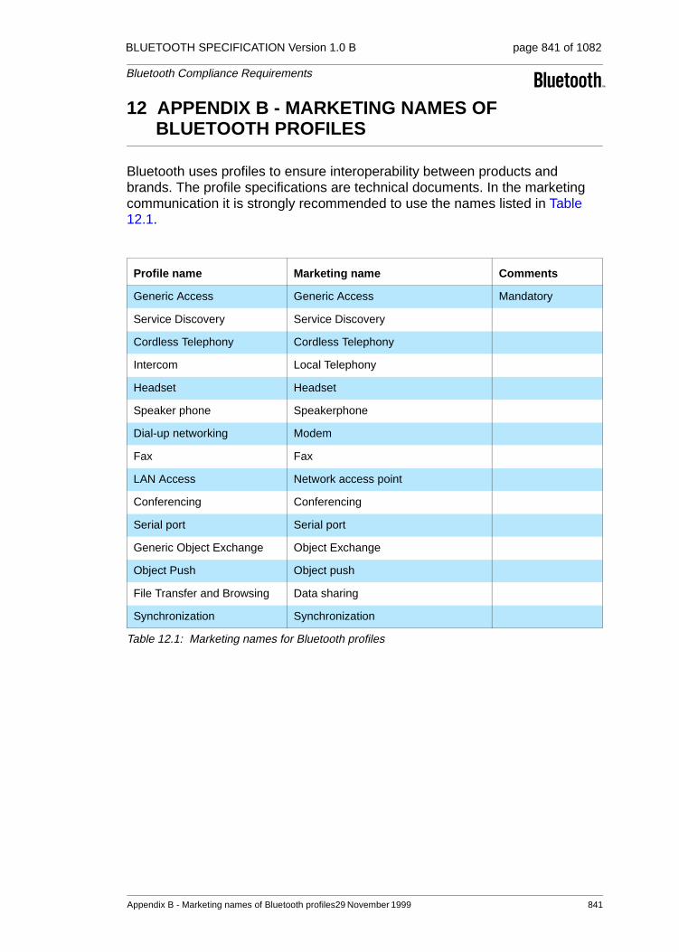
BLUETOOTH SPECIFICATION Version 1.0 B page 841 of 1082
Bluetooth Compliance Requirements
12 APPENDIX B - MARKETING NAMES OF BLUETOOTH PROFILES
Bluetooth uses profiles to ensure interoperability between products and brands. The profile specifications are technical documents. In the marketing communication it is strongly recommended to use the names listed in Table 12.1.
Profile name Marketing name Comments
Generic Access Generic Access Mandatory
Service Discovery Service Discovery
Cordless Telephony Cordless Telephony
Intercom Local Telephony
Headset Headset
Speaker phone Speakerphone
Dial-up networking Modem
Fax Fax
LAN Access Network access point
Conferencing Conferencing
Serial port Serial port
Generic Object Exchange Object Exchange
Object Push Object push
File Transfer and Browsing Data sharing
Synchronization Synchronization
Table 12.1: Marketing names for Bluetooth profiles
Appendix B - Marketing names of Bluetooth profiles29 November 1999 841

BLUETOOTH SPECIFICATION Version 1.0 B page 842 of 1082
Bluetooth Compliance Requirements
842 29 November 1999 Appendix B - Marketing names of Bluetooth
Part I:3
TEST CONTROL INTERFACE
This document describes the Bluetooth Test Control Interface (TCI). The TCI provides a uni-form method of accessing the upper interface of the System Under Test (SUT) and/or the Implementation Under Test (IUT).

BLUETOOTH SPECIFICATION Version 1.0 B page 844 of 1082
Test Control Interface
844 29 November 1999
BLUETOOTH SPECIFICATION Version 1.0 B page 845 of 1082
Test Control Interface
CONTENTS
1 Introduction ......................................................................................8471.1 Terms Used..............................................................................8471.2 The needs for a unified test interface.......................................8471.3 Usage of the interface..............................................................848
2 General Description .........................................................................8492.1 Baseband and Link Management verification ..........................8492.2 HCI verification.........................................................................8512.3 L2CAP verification....................................................................852
3 Test Configurations..........................................................................8543.1 Bluetooth RF Link requirements...............................................854
3.1.1 Required Interface(s)...................................................8543.2 Bluetooth protocol requirements ..............................................854
3.2.1 Required Interface(s)...................................................8553.3 Bluetooth profile requirements .................................................855
3.3.1 Required Interface(s)...................................................855
4 TCI-L2CAP Specification .................................................................8564.1 Events ......................................................................................856
4.1.1 Connect Indication.......................................................8564.1.2 Configuration Indication...............................................8574.1.3 Disconnect Indication ..................................................8574.1.4 Violation Indication ......................................................857
4.2 Commands...............................................................................8574.2.1 Connection Establishment...........................................8584.2.2 Connect Response......................................................8594.2.3 Connection Release (Disconnect)...............................8594.2.4 Configuration ...............................................................8594.2.5 Configure Response....................................................8604.2.6 Disable Connectionless Traffic ....................................8604.2.7 Enable Connectionless Traffic.....................................8604.2.8 Group Create...............................................................8604.2.9 Group Close ................................................................8614.2.10 Group Add Member.....................................................8614.2.11 Group Remove Member..............................................8624.2.12 Group Membership......................................................8624.2.13 Ping .............................................................................8624.2.14 Get Info........................................................................863
29 November 1999 845

BLUETOOTH SPECIFICATION Version 1.0 B page 846 of 1082
Test Control Interface
4.3 Data Transfer ...........................................................................8634.3.1 Write............................................................................8634.3.2 Read ...........................................................................864
5 Abbreviations ...................................................................................866
846 29 November 1999

BLUETOOTH SPECIFICATION Version 1.0 B page 847 of 1082
Test Control Interface
1 INTRODUCTION
1.1 TERMS USED
IUT = Implementation Under Test: An implementation of one or more OSI pro-tocols in an adjacent user/provider relationship, being that part of a real open system which is to be studied by testing.This term will be used when describing the test concept for Bluetooth acces-sory products and Bluetooth components. The definition of Bluetooth acces-sory products and Bluetooth components can be found in Part I:2 / Section 6.5.1 on page 834 and in Part I:2 / Section 6.6.1 on page 834.
SUT = System Under Test: The real open system in which the IUT resides.This term will be used when describing the test concept for Bluetooth products.
TCI = Test Control Interface: The interface and protocol used by the tester to send and receive commands and messages to and from the upper interface of the SUT/IUT.
1.2 THE NEEDS FOR A UNIFIED TEST INTERFACE
For all Bluetooth accessory products, Bluetooth components and Bluetooth products, protocol testing will be used to verify the implemented functionality in the lowest layers; i.e. conformance testing.
For this type of testing, an upper tester (UT) will be required to completely test the implementation.
In order to shield the tester from having to adopt to each and every implemen-tation of IUTs or SUTs, the use of a standardized control interface is mandated. This concept puts some extra burden upon the manufacturer of the IUT/SUT. The manufacturer must:
• adopt the implementation-dependent interface to the TCI
• supply, with the IUT, the adapter needed (can be HW, SW or FW)
Introduction 29 November 1999 847

BLUETOOTH SPECIFICATION Version 1.0 B page 848 of 1082
Test Control Interface
1.3 USAGE OF THE INTERFACE
The Bluetooth Test Control Interface, TCI, will be used when verifying the Blue-tooth protocol requirements for a Bluetooth accessory product, Bluetooth com-ponent or a Bluetooth product. More specifically, the TCI will be used when verifying implemented functionality of the:
• Baseband layer, BB (the protocol-related part)
• Link Manager Protocol, LMP
• Logical Link Control and Adaptation Protocol, L2CAP
and, if support of the HCI is claimed by the manufacturer:
• Host Control Interface, HCI
848 29 November 1999 Introduction

BLUETOOTH SPECIFICATION Version 1.0 B page 849 of 1082
Test Control Interface
2 GENERAL DESCRIPTION
The interface used between the tester and the SUT/IUT will be either of two types:
1. TCI-HCIThis interface is semantically and syntactically identical to the HCI interface described in “Part H:1” on page 517.
2. TCI-L2CAPThis interface is based on the HCI interface, and will be used during verifica-tion of the L2CAP layer of the SUT/IUT.
The proposed physical bearer is one of the transport layers specified for the HCI: USB, RS232 or UART, see “Part H:2” on page 759, “Part H:3” on page 775 or “Part H:4” on page 795. However, alternatives do exist. More details will be given in the following sections.
2.1 BASEBAND AND LINK MANAGEMENT VERIFICATION
For the verification of the link control part of the Baseband layer and for the Link Manager layer, the TCI-HCI interface will be used as the interface between the test system and the upper interface of the SUT/IUT. The test sys-tem accesses the upper interface of the SUT/IUT by sending HCI commands and receiving HCI events from the SUT/IUT as described in the “Host Control-ler Interface Functional Specification” on page 517. The supported functionality on the TCI-HCI interface depends on the implemented functionality of the BB and LM layers.
The transport bearer used between the tester and the SUT/IUT can be of either of two types:
1. A physical bearer of one of the types USB, RS232 or UART, as defined in Part H:2, Part H:3 or Part H:4. It is recommended to use one of these three physical bearers as transport bearer between the SUT/IUT and the test sys-tem.
2. A ‘software’ transfer bearer; i.e. there is no physical connection between the tester and the SUT/IUT. In this case, the manufacturer of the SUT/IUT must supply, when sending in the device for testing, a test software that can be operated by a test operator. The operator will receive instructions from the tester and will execute them on the SUT/IUT. The software must support the same functionality as if using the TCI-HCI with a physical bearer. Use of the ‘software’ interface must be agreed upon between the manufacturer of the SUT/IUT and the test facility that will perform the verification. The test facili-ties can themselves specify requirements placed on such an interface.
A schematic example is shown in Figure 2.1 of a possible test configuration for BB and LM verification of Bluetooth products which do not support HCI, and which use a physical transport bearer for the TCI-HCI interface. In this figure,
General Description 29 November 1999 849

BLUETOOTH SPECIFICATION Version 1.0 B page 850 of 1082
Test Control Interface
the TC (Test Control) Software represents what the manufacturer has to supply with the SUT/IUT when sending it in for verification. The functionality of the TC software is to adapt the implementation-dependent interface to the TCI-HCI interface.
Figure 2.1: Baseband and LM verification without HCI – physical transport bearer
Figure 2.2 shows a schematic example of the test configuration for the same Bluetooth product using a ‘software’ transfer bearer for the TCI-HCI interface. Here, the role of the TC Software is to represent the application that can be controlled by the test operator.
Test system
IUT
RF
BB
LM
TC Software
Physical Bus
HCI Firmware
Adapter Physical Bus
HCI DriverTCI-HCI
TCI
Implementationdependent interface
RF
BB
LMLMP
LCP
AirInterface
Test SuiteExecutor
850 29 November 1999 General Description

BLUETOOTH SPECIFICATION Version 1.0 B page 851 of 1082
Test Control Interface
Figure 2.2: Baseband and LM verification without HCI – software transport bearer
2.2 HCI VERIFICATION
The TCI-HCI interface may also be used for HCI signalling verification. The HCI signalling will only be verified if support of the HCI functionality is claimed by the manufacturer.
The transport bearer between the tester and the SUT/IUT shall be one of the types USB, RS232, or UART, as defined in Part H:2, Part H:3 or Part H:4.
A schematic example is shown in Figure 2.3 of one possible test configuration for HCI verification of Bluetooth products, using a physical transport bearer for the TCI-HCI interface. As can be seen from the figure, no extra test control software is needed. Instead, the implemented HCI will be used as the interface to the tester.
Test system
IUT
RF
BB
LM
TC Software
TestApplicationAdapter
TestOperator
Interface withMMI
TCI
Implementationdependent interface
RF
BB
LMLMP
LCP
AirInterface
Execute Command
Report Event
Test SuiteExecutor
General Description 29 November 1999 851

BLUETOOTH SPECIFICATION Version 1.0 B page 852 of 1082
Test Control Interface
Figure 2.3: HCI verification
2.3 L2CAP VERIFICATION
The TCI-L2CAP interface is based on the HCI and will be used during verifica-tion of the L2CAP layer of the SUT/IUT. It uses the general event and com-mand syntax as specified in Part H:1, and the mapping to transport layers is also identical to the ones defined in Part H:2, Part H:3 or Part H:4. Commands and events are defined according to the specified L2CAP service interface. See Part D / Section 7 on page 295.
The defined service primitives in the Logical Link and Control Layer specifica-tion, Part D / Section 7 on page 295, will be used as reference. However, the primitives for L2CAP events and commands must be converted into messages of the same format as used for the HCI events and commands. The mapping of the L2CAP events and commands to HCI format is described in Section 4 of this document.
A schematic example is shown in Figure 2.4. of how the test configuration can look for L2CAP verification of Bluetooth products, using a physical transport bearer for the TCI-L2CAP interface. In this figure, the TC (Test Control) Soft-ware represents what the manufacturer has to supply with the SUT/IUT when sending it in for verification. The functionality of the TC software is to adapt the implementation-dependent interface to the TCI-L2CAP interface.
Test systemIUT
RF
BB
LM
Physical BusUSB,RS232 or UART
Physical Bus
HCI DriverHCI
TCI
RF
BB
LMLMP
LCP
AirInterface
HCI Firmware Test SuiteExecutor
852 29 November 1999 General Description

BLUETOOTH SPECIFICATION Version 1.0 B page 853 of 1082
Test Control Interface
Figure 2.4: L2CAP verification
Test system
IUT
RF
BB
LM
TC Software
Physical Bus
TCI-L2CAPFirmware
Adapter Physical Bus
TCI-L2CAPDriver
TCI-L2CAP
TCI
Implementationdependent interface
RF
BB
LM
AirInterface
L2CA L2CAP L2CA
Test SuiteExecutor
General Description 29 November 1999 853

BLUETOOTH SPECIFICATION Version 1.0 B page 854 of 1082
Test Control Interface
3 TEST CONFIGURATIONS
This section describes the test configurations that will be used when verifying the different Bluetooth requirements.
3.1 BLUETOOTH RF LINK REQUIREMENTS
For the verification of the Bluetooth RF Link requirements, the defined test mode will be used, see “Part I:1” on page 803.
The Test Specification for the Bluetooth radio link requirements will be based on the Bluetooth specification Parts A and B, and will contain the relevant test instructions that should be carried out on the SUT/IUT.
3.1.1 Required Interface(s)
For this type of verification, only the air interface is required. See Figure 3.1. As stated in Part I:1 / Section 1.2 on page 807, for security reasons, the test mode must be locally enabled. The implementation of this local enabling is not subject to standardization.
Figure 3.1: Test Configuration for RF link requirement verification
3.2 BLUETOOTH PROTOCOL REQUIREMENTS
Dependent on which Bluetooth layers BB, LM, HCI or L2CAP are implemented in the product sent in for verification, the amount of testing needed to verify the Bluetooth protocol requirements will differ. Also, the TCI used during the verifi-cation may be different.
Test systemIUT
RF
BB
LM
Implementationdependent interface
RF
BB
LMLMP
AirInterface
Local activation/enabling
Used for test modesignalling
854 29 November 1999 Test Configurations
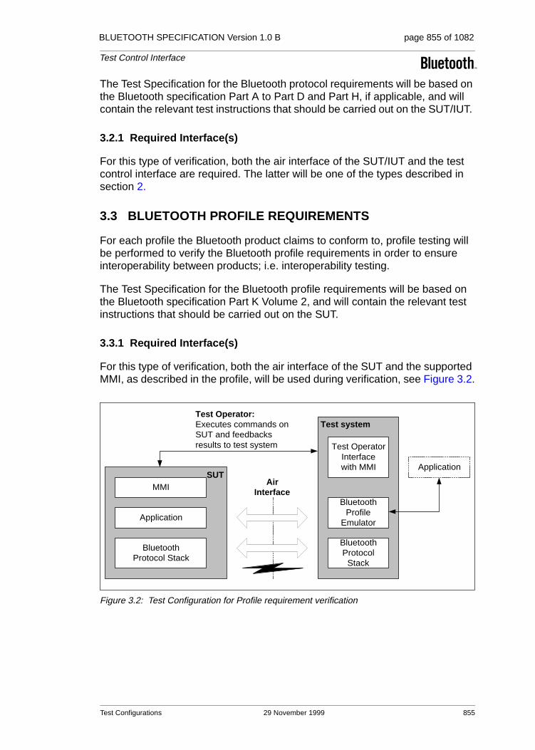
BLUETOOTH SPECIFICATION Version 1.0 B page 855 of 1082
Test Control Interface
The Test Specification for the Bluetooth protocol requirements will be based on the Bluetooth specification Part A to Part D and Part H, if applicable, and will contain the relevant test instructions that should be carried out on the SUT/IUT.
3.2.1 Required Interface(s)
For this type of verification, both the air interface of the SUT/IUT and the test control interface are required. The latter will be one of the types described in section 2.
3.3 BLUETOOTH PROFILE REQUIREMENTS
For each profile the Bluetooth product claims to conform to, profile testing will be performed to verify the Bluetooth profile requirements in order to ensure interoperability between products; i.e. interoperability testing.
The Test Specification for the Bluetooth profile requirements will be based on the Bluetooth specification Part K Volume 2, and will contain the relevant test instructions that should be carried out on the SUT.
3.3.1 Required Interface(s)
For this type of verification, both the air interface of the SUT and the supported MMI, as described in the profile, will be used during verification, see Figure 3.2.
Figure 3.2: Test Configuration for Profile requirement verification
Test system
SUT
BluetoothProtocol Stack
Application
BluetoothProtocol
Stack
AirInterfaceMMI
BluetoothProfile
Emulator
Test OperatorInterfacewith MMI
Test Operator:Executes commands onSUT and feedbacksresults to test system
Application
Test Configurations 29 November 1999 855

BLUETOOTH SPECIFICATION Version 1.0 B page 856 of 1082
Test Control Interface
4 TCI-L2CAP SPECIFICATION
Note: This specification maps the L2CAP service interface to an appropriate TCI. This section is based on the 0.95b version of the L2CAP specification.
4.1 EVENTS
In the L2CAP service interface, indications are mapped to callback functions. The corresponding response parameters are submitted in the return parameter of these functions. For the TCI, the indications are mapped to events and the responses to commands.
A single event code is reserved for testing purposes: 0xFE. To distinguish the L2CAP events, a parameter ‘Event_ID’ is submitted as first parameter. This parameter is a single octet, resulting in 256 possible events. The assignment is given in Table 4.1.
The events in this test interface follow the HCI syntax as defined in Part H:1 / Section 4.4.2 on page 535.
4.1.1 Connect Indication
For more details and the event parameter, see Part D / Section 7.1 on page 295.
Event_ID L2CAP event
0x00 Reserved
0x01 L2CA_ConnectInd
0x02 L2CA_ConfigInd
0x03 L2CA_DisconnectInd
0x04 L2CA_QoSViolationInd
0x05 – 0xFF Reserved
Table 4.1: Assignment of event IDs
Event Event Code Event Parameters
L2CA_ConnectInd 0xFE Event_ID, BD_ADDR, CID, PSM, Identifier
856 29 November 1999 TCI-L2CAP Specification

BLUETOOTH SPECIFICATION Version 1.0 B page 857 of 1082
Test Control Interface
4.1.2 Configuration Indication
For more details and the event parameter, see Part D / Section 7.1 on page 295.
4.1.3 Disconnect Indication
For more details and the event parameter, see Part D / Section 7.1 on page 295.
4.1.4 Violation Indication
For more details and the event parameter, see Part D / Section 7.1 on page 295.
4.2 COMMANDS
The commands in this test interface follow the HCI syntax as defined in Part H:1 / Section 4.4.1 on page 532. The return parameters are sent back using a Command Complete event, see Part H:1 / Section 5.2.14 on page 723 and Part H:1 / Section 4.4.1 on page 532.
To distinguish the commands used for L2CAP testing from HCI commands, a single subgroup is reserved for the L2CAP test interface. Figure 4.1 shows how to code and decode the OpCode field in the HCI command packet used for testing.
Figure 4.1: HCI Opcode field values used for testing
Event Event Code Event Parameters
L2CA_ConfigInd 0xFE Event_ID, CID, OutMTU, InFlow, FlushTO
Event Event Code Event Parameters
L2CA_DisconnectInd 0xFE Event_ID, CID
Event Event Code Event Parameters
L2CA_QoSViolationInd 0xFE Event_ID, BD_ADDR
0 1684 12
LSB MSB
0x3ESubgroup for testing
0 1 1 1 1 1
0x0001 - 0x03FFOCF range for testing purposes
OpCode field in HCI command packet
TCI-L2CAP Specification 29 November 1999 857

BLUETOOTH SPECIFICATION Version 1.0 B page 858 of 1082
Test Control Interface
The assignment of the OpCode Command Field, OCF, for the L2CAP com-mands is summarized in Table 4.2. It is also detailed following the table, in a format similar to the HCI specification, see “Part H:1” on page 517.
4.2.1 Connection Establishment
OCF L2CAP command
0x0000 Reserved
0x0001 L2CA_ConnectReq
0x0002 L2CA_DisconnectReq
0x0003 L2CA_ConfigReq
0x0004 L2CA_DisableCLT
0x0005 L2CA_EnableCLT
0x0006 L2CA_GroupCreate
0x0007 L2CA_GroupClose
0x0008 L2CA_GroupAddMember
0x0009 L2CA_GroupRemoveMember
0x000A L2CA_GroupMemebership
0x000B L2CA_WriteData
0x000C L2CA_ReadData
0x000D L2CA_Ping
0x000E L2CA_GetInfo
0x000F Reserved
0x0010 Reserved
0x0011 L2CA_ConnectRsp
0x0012 Reserved
0x0013 L2CA_ConfigRsp
0x0014 – 0x03FF Reserved
Table 4.2: Assignment of Opcode Command Field values
Command OCF Command Parameters Return Parameters
L2CA_ConnectReq 0x0001 PSM, BD_ADDR LCID, Result, Status
858 29 November 1999 TCI-L2CAP Specification
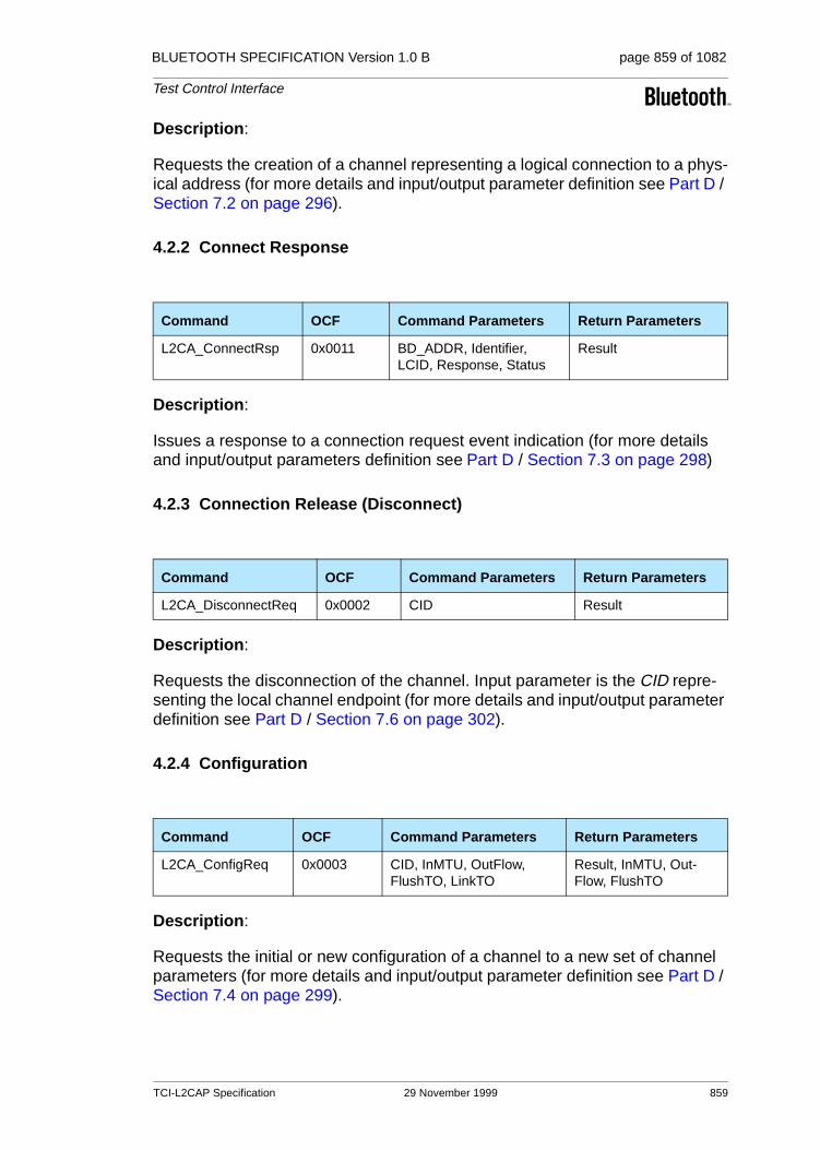
BLUETOOTH SPECIFICATION Version 1.0 B page 859 of 1082
Test Control Interface
Description:
Requests the creation of a channel representing a logical connection to a phys-ical address (for more details and input/output parameter definition see Part D / Section 7.2 on page 296).
4.2.2 Connect Response
Description:
Issues a response to a connection request event indication (for more details and input/output parameters definition see Part D / Section 7.3 on page 298)
4.2.3 Connection Release (Disconnect)
Description:
Requests the disconnection of the channel. Input parameter is the CID repre-senting the local channel endpoint (for more details and input/output parameter definition see Part D / Section 7.6 on page 302).
4.2.4 Configuration
Description:
Requests the initial or new configuration of a channel to a new set of channel parameters (for more details and input/output parameter definition see Part D / Section 7.4 on page 299).
Command OCF Command Parameters Return Parameters
L2CA_ConnectRsp 0x0011 BD_ADDR, Identifier, LCID, Response, Status
Result
Command OCF Command Parameters Return Parameters
L2CA_DisconnectReq 0x0002 CID Result
Command OCF Command Parameters Return Parameters
L2CA_ConfigReq 0x0003 CID, InMTU, OutFlow, FlushTO, LinkTO
Result, InMTU, Out-Flow, FlushTO
TCI-L2CAP Specification 29 November 1999 859

BLUETOOTH SPECIFICATION Version 1.0 B page 860 of 1082
Test Control Interface
4.2.5 Configure Response
Description:
Issues a response to a configuration request event indication (for more details and input/output parameter definition see Part D / Section 7.5 on page 301).
4.2.6 Disable Connectionless Traffic
Description:
For details and input/output parameter definition see Part D / Section 7.16 on page 311.
4.2.7 Enable Connectionless Traffic
Description:
For details and input/output parameter definition see Part D / Section 7.17 on page 312.
4.2.8 Group Create
Command OCF Command Parameters Return Parameters
L2CA_ConfigRsp 0x0013 CID, OutMTU, InFlow Result
Command OCF Command Parameters Return Parameters
L2CA_DisableCLT 0x0004 N, List of PSMs Result
Command OCF Command Parameters Return Parameters
L2CA_EnableCLT 0x0005 N, List of PSMs Result
Command OCF Command Parameters Return Parameters
L2CA_GroupCreate 0x0006 PSM CID
860 29 November 1999 TCI-L2CAP Specification

BLUETOOTH SPECIFICATION Version 1.0 B page 861 of 1082
Test Control Interface
Description:
Request the creation of a channel identifier to represent a logical connection to multiple devices. On creation, the group is empty (for more details and input/output parameter definition see Part D / Section 7.9 on page 305).
4.2.9 Group Close
Description:
This command closes down a Group (for more details and input/output param-eter definition see Part D / Section 7.10 on page 305).
4.2.10 Group Add Member
Description:
This command adds a member to the group (for more details and input/output parameter definition see Part D / Section 7.11 on page 306).
Command OCF Command Parameters Return Parameters
L2CA_GroupClose 0x0007 CID Result
Command OCF Command Parameters Return Parameters
L2CA_GroupAddMember 0x0008 CID, BD_ADDR Result
TCI-L2CAP Specification 29 November 1999 861

BLUETOOTH SPECIFICATION Version 1.0 B page 862 of 1082
Test Control Interface
4.2.11 Group Remove Member
Description:
Remove a member from the group (for more details and input/output parame-ter definition see Part D / Section 7.12 on page 307).
4.2.12 Group Membership
Description:
Get report of the members of the group (for more details and input/output parameter definition see Part D / Section 7.13 on page 308).
4.2.13 Ping
Description:
For more details and input/output parameter definition see Part D / Section 7.14 on page 309.
Command OCF Command Parameters Return Parameters
L2CA_GroupRemoveMember 0x0009 CID, BD_ADDR Result
Command OCF Command Parameters Return Parameters
L2CA_GroupMembership 0x000A CID Result, N, BD_ADDR_Lst
Command OCF Command Parameters Return Parameters
L2CA_Ping 0x000D BD_ADDR, ECHO_DATA Result, ECHO_DATA
862 29 November 1999 TCI-L2CAP Specification

BLUETOOTH SPECIFICATION Version 1.0 B page 863 of 1082
Test Control Interface
4.2.14 Get Info
Description:
For more details and input/output parameter definition see Part D / Section 7.15 on page 310.
4.3 DATA TRANSFER
Data transfer is modelled with read and write functions. Handling is like an L2CAP command.
To be able to send the amount of data that is needed to verify how the L2CAP implementation handles large chunks of data (i.e. segmentation and reassem-bly), and since it is not possible to use HCI Command packets as well as HCI Event packets to send the data, the use of HCI ACL Data packets will be used. The procedure/signalling used on the TCI-L2CAP interface to transfer data packets will be described with MSCs.
4.3.1 Write
Description:
Parameters are the CID, the length of the data and the data itself. The data will be sent in a HCI ACL data packets as described in Figure 4.2. For more details and input/output parameter definition see Part D / Section 7.7 on page 303.
Command OCF Command Parameters Return Parameters
L2CA_GetInfo 0x000E BD_ADDR, InfoType Result, InfoData
Command OCF Command Parameters Return Parameters
L2CA_WriteData 0x000B CID, Length, OutBuffer Size, Result
TCI-L2CAP Specification 29 November 1999 863

BLUETOOTH SPECIFICATION Version 1.0 B page 864 of 1082
Test Control Interface
Figure 4.2: MSC showing how to write data to L2CAP
The L2CA_Data primitive is used as an abstract name for the data transmitted between the Tester and the IUT. The Tester will use Connection Handle 0x0001 for the data and will set the Flags-field to 0x02. The Data Total Length field will contain the length of the OutBuffer.
After the IUT has received the data, it shall send back an HCI Command Com-plete Event (named L2CAP_WriteData in the figure) with the N parameter set to 0x01, the OpCode parameter set to the corresponding OCF and subgroup (that is OCF = 0x000B and the subgroup = 0x3E). The Size and Result are sent in the Return_Parameters field of the HCI ACL Data packet.
4.3.2 Read
Description:
Input parameter is the CID, length and the InBuffer. Output parameters are the result. The data will be sent in HCI ACL data packets as described in Figure 4.3. For more details and input/output parameter definition see Part D / Section 7.8 on page 304).
Command OCF Command Parameters Return Parameters
L2CA_ReadData 0x000C CID, Length, InBuffer Result
Tester IUT
L2CA_WriteData(CID, Length)
L2CA_Data(OutBuffer)
L2CA_WriteData(Size, Result)HCI Command Complete Eventwith Size and Result as Return_Parameters
HCI ACL Data Packetwith Length as Data Total Lengthand OutBuffer as Data
HCI Command Packetwith CID and Length as parameters
864 29 November 1999 TCI-L2CAP Specification

BLUETOOTH SPECIFICATION Version 1.0 B page 865 of 1082
Test Control Interface
Figure 4.3: MSC showing how to read data from L2CAP
The L2CA_Data primitive is used as an abstract name for the data transmitted between the Tester and the IUT. The IUT shall use Connection Handle 0x0001 for the data and shall set the Flags-field to 0x02. The Data Total Length field shall contain the length of the InBuffer.
After the IUT has sent the data, it shall send back an HCI Command Complete Event (named L2CAP_ReadData in the figure) with the N parameter set to 0x01, the OpCode parameter set to the corresponding OCF and subgroup (that is OCF = 0x000C and the subgroup = 0x3E). The Size and Result are sent in the Return_Parameters field of the HCI ACL Data packet.
Tester IUT
L2CA_ReadData(CID,Length)
L2CA_Data(InBuffer)
L2CA_ReadData(Result)
HCI Command Packetwith CID and Length as parameters
HCI ACL Data Packetwith Length as Data Total Lengthand InBuffer as Data
HCI Command Complete Eventwith Result as Return_Parameters
TCI-L2CAP Specification 29 November 1999 865

BLUETOOTH SPECIFICATION Version 1.0 B page 866 of 1082
Test Control Interface
5 ABBREVIATIONS
BB BaseBand (see LC)
FW Firmware
HCI Host Controller Interface
HW Hardware
IUT Implementation Under Test
L2CA Logical Link Control And Management part of the Bluetooth protocol stack
L2CAP Logical Link Control And Management Protocol
LC Link Controller (or baseband) part of the Bluetooth protocol stack
LCP Link Control Protocol
LM Link Manager part of the Bluetooth Protocol Stack
LMP Link Management Protocol
MMI Man-Machine Interface
OCF Opcode Command Field
RF Radio part of the Bluetooth protocol stack
SUT System Under Test
SW Software
TC Test Control layer for the test interface
TCI Test Control Interface
UART Universal Asynchronous receiver Transmitter
USB Universal Serial Bus
UT Upper Tester
866 29 November 1999 Abbreviations

Appendix I
REVISION HISTORY

BLUETOOTH SPECIFICATION Version 1.0 B page 868 of 1082
Appendix I - Revision History
Revision History
Part A / Radio Specification
Part B / Baseband Specification
Rev Date Comments
0.8Jan 21st 1999
• System ambient temperature range • Power control step size • Transmit Spectrum mask • Frequency drift in a packet • New paragraph "Receiver susceptibility to frequency drift"• Adjacent interference levels • Measurement frequency for intermodulation test• Maximum useable level defined• New paragraph "Reference Interference-Signal Definition"
0.9April30th1999
• Eye-diagram added• Out-of band blocking included• RSSI included
1.0 draft
July 5th 1999
• Appendix A and B added, (extreme conditions definition and test condi-tions)
• Tolerances of the Eye-diagram added
1.0BDec1st1999
• Revised from a linguistic point of view.• Errata items previously published on the web has been included.
These corrections and clarifications are marked with correction bars.
Rev Date Comments
0.7Oct 19th 1998
• Minor changes in chapter 1-9.• ”Link Monitoring” chapter removed (chapter 12 in v0.6).• Most parts of chapter 10 - 14 re-written.
0.8Jan 21st 1999
• Some editorial changes in chapter 1-13.• Chapter 14 revised and partly re-written.
1.0 draft
July 5th 1999
• Please see revision bars in document.
1.0BDec1st1999
• Revised from a linguistic point of view.• Errata items previously published on the web has been included.
These corrections and clarifications are marked with correction bars.
868 29 November 1999

BLUETOOTH SPECIFICATION Version 1.0 B page 869 of 1082
Appendix I - Revision History
Part C / Link Manager Protocol
Rev Date Comments
0.7Oct 19th 1998
• EEE address ⇒ BD_ADDR (or BD address)• M_ADDR ⇒ AM_ADDR• response nbr ⇒ PM_ADDR• Added section 3.1.4• Added section 3.4 “Change the current link key”• Changed section 3.5 “Encryption”. Added negotiation for encryption mode
and encryption key size.• 3.14 “Sniff mode”. Removed author’s note in italic. It is now decided how to
determine the first sniff slot.• 3.15 “Park mode”. This section is totally changed.• 3.18 “Quality of Service”. Added a parameter NBC in one of the LMP mes-
sages.• 3.19 “SCO links”. Removed author’s note in italic. It is now decided how to
determine the first SCO slot.• Added section 4 “Connection establishment”• 5.1 “Description of parameters” The length, type and unit of many parame-
ters changed. Especially, all time-parameters are now measured in slots.• Added section 6 “Test modes”
0.8Jan 21st 1999
• general: Changed "PDU nbr" to OpCode throughout the document. Two errors found in 0.80 were corrected. Table5.1: It says that the length of LMP_SCO_link_req is 7. This should be 8. Table 5.2: It says that the length of hold_time is 1. This should be 2.
• 2. Added transactionID in bit0 of the byte in the payload where we have the OpCode.
• 3.1 Removed LMP_accepted/not_accepted after receiving LMP_sres (3.1).• 3.1.2 Removed the last sentence "It the claimant is Ö initiate pairing, see
3.2.1"• 3.2 Major change since the initiator of the pairing procedure does not have
to be the master.• 3.2.3 Minor clarification.• 3.3 Clearified that if the unit key is changed, the units must go through the
initialisation procedure in order to change the link key.• 3.5.3 Modified the calculation of Kc according to changes in chapter 14 of
the Baseband Specification. • 3.10 Switch can now be done anytime during the connection and it can be
initiated by both master and slave.• 3.15 Clearified that the broadcast scan window is only valid for the current
beacon.• 3.19.5 Added description that the PDU includes a reason parameter with
information about why the SCO link is removed. • 3.21 This section was removed. Instead error handling is described in a
separate chapter (CH. 7)• 4. Added LMP_host_connection_req and removed the LMP_accepted or
LMP_not_accepted that the slave sends after the paging procedure.• 5.1 Added reason "invalid parameters"• 6. Added sequences. The slave can return LMP_not_accepted if not
allowed to enter test or if not in test mode. Changed OpCodes for the two test mode PDU
29 November 1999 869

BLUETOOTH SPECIFICATION Version 1.0 B page 870 of 1082
Appendix I - Revision History
0.9April30th1999
• Name request procedure: Coding of the characters was changed from ASCII to UTF-8. The length of the name parameter was increased from 16 bytes to 248 bytes.
• The detach reason and the reason parameter were merged into one parameter (reason). The coding of this parameter was changed and is now the same as in HCI.
• Sniff procedure: Sniff interval and sniff offset parameters were changed from one byte to two bytes. Two parameters, sniff offset and sniff timeout, were also added.
• The PDU LMP_slot_offset was added.• The PDU LMP_page_mode_req was added.• The PDU LMP_page_scan_mode_req was added.• Caption text was added to all figures, tables and sequences where such
text was missing.• A maximum reply time was defined for response messages in LMP proce-
dures.• The pairing procedure was modified to allow a claimant with fixed PIN to
request to become verifier.• Changed some parameters in LMP_test_control to match the latest revi-
sion of "Bluetooth test modes".• The PDU LMP_supervision_timeout was added.• The parameter user data rate was removed from the PDU LMP_SCO_link
request.• The length of the parameters CompId and SubVersNr included in the PDU
LMP_version_req/res was increased to two bytes.• Some editorial changes and clarifications were made here and there.
1.0 draft
July 5th 1999
• Added figure 3 explaining sequence diagram conventions (Section 3).• Modified procedure to negotiate encryption key size to match changes in
the Baseband specification (Section 3.6.2).• Added further description about the parameters in the version request
(Section 3.10).• Clearified name request procedure and changed parameter name from
"name" to "name fragment" (Section 3.13).• Added description that test mode can also be ended by sending
LMP_test_control (Section 6.1).• Some editorial comments.• Decoupled RSSI and power control in the features parameter. Changed
parameter "TBD" to "for future use".• Rewrote Section 3.20.
1.0aJuly 26th 1999
• Correction of Table 5.3: Byte 1/Bit 1 “and power control” deletedByte 2/Bit 2 “power control” added
1.0BDec1st1999
• Revised from a linguistic point of view.• Errata items previously published on the web has been included.
These corrections and clarifications are marked with correction bars.
870 29 November 1999
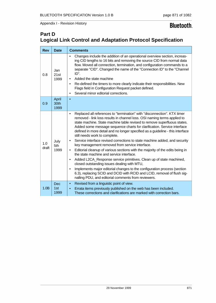
BLUETOOTH SPECIFICATION Version 1.0 B page 871 of 1082
Appendix I - Revision History
Part DLogical Link Control and Adaptation Protocol Specification
Rev Date Comments
0.8Jan 21st 1999
• Changes include the addition of an operational overview section, increas-ing CID lengths to 16 bits and removing the source CID from normal data flow. Moved all connection, termination, and configuration commands to a separate "CID". Changed the name of the "Connection ID" to the "Channel ID".
• Added the state machine• Re-defined the timers to more clearly indicate their responsibilities. New
Flags field in Configuration Request packet defined.• Several minor editorial corrections.
0.9April30th1999
•
1.0 draft
July 5th 1999
• Replaced all references to "termination" with "disconnection". KTX timer removed - link loss results in channel loss. OSI naming terms applied to state machine. State machine table revised to remove superfluous states. Added some message sequence charts for clarification. Service interface defined in more detail and no longer specified as a guideline - this interface still needs work to complete.
• Service interface revised corrections to state machine added, and security key management removed from service interface.
• Editorial cleanup of various sections with the majority of the edits being in the state machine and service interface.
• Added L2CA_Response service primitives. Clean up of state machined, closed outstanding issues dealing with MTU,
• Implements major editorial changes to the configuration process (section 6.3), replacing SCID and DCID with RCID and LCID, removal of flush sig-nalling PDU, and editorial comments from reviewers.
1.0BDec1st1999
• Revised from a linguistic point of view.• Errata items previously published on the web has been included.
These corrections and clarifications are marked with correction bars.
29 November 1999 871

BLUETOOTH SPECIFICATION Version 1.0 B page 872 of 1082
Appendix I - Revision History
Part E / Service Discovery Protocol (SDP)
Part F:1 / RFCOMM with TS 0710
Rev Date Comments
1.0 draft
July 5th 1999
• Removed the Icon10 attribute and the Icon data element type. Re-assigned the IconURL attribute ID to be 0x000C. Updated Example 3. Removed "notes to reviewers". Removed the list of TBD items, since it is empty.
• A few corrections to example 3. Modified the BluetoothProfileList attribute to become the BluetoothProfileDescriptorList attribute, which contains a version number for each profile as well as the profile's UUID
• Added a description of the protocol version number included in the Blue-toothProfileDescriptorList attribute. No change to the 'phonebook' and 'cal-endar' data store indicators as the values in example 3 already match those of the synchronization profile. Replaced the browse hierarchy diagram in 2.8.1 because the previous version triggered a bug in MS-Word.
1.0BDec1st1999
• Revised from a linguistic point of view.• Errata items previously published on the web has been included.
These corrections and clarifications are marked with correction bars.
Rev Date Comments
0.8Jan 21st 1999
• Table 2.1 corrected. • Revised section 2.3.• Revised chapter 3. • Revised section 5.2, 5.3.• Clarifications added to Figure 5.1. • Changed title and contents of section 5.4 (old section 5.4 not needed any
more). • Text removed from section 5.5 and 5.6. • Added text on Service Discovery in section 7.3.
0.9April30th1999
• Lots of editorial changes and clarifications.• Added statement on baud rate settings vs. RFCOMM throughput in chapter
2.• Removed section 7.2 on flow control (information duplicated in TS 07.10). • Added DLC parameter negotiation command support (section 4.3, 5.7)• Added clarifications on session closure handling in section 5.2. • Major update regarding SDP; section 7.2. • Added section 7.3 on lower layer dependencies.
1.0 draft
July 5th 1999
• Editorial changes and clarifications in chapters 5 and 7.• Removed sections implying possibility to have more than one RFCOMM
entity in a device.
1.0BDec1st1999
• Revised from a linguistic point of view.• Errata items previously published on the web has been included.
These corrections and clarifications are marked with correction bars.
872 29 November 1999

BLUETOOTH SPECIFICATION Version 1.0 B page 873 of 1082
Appendix I - Revision History
Part F:2 / IrDA Interoperability
Part F:3 / Telephony Control Specification (TCS)
Part F:4Interoperability Requirements for Bluetooth as a WAP Bearer
Rev Date Comments
0.9April30th1999
• Many linguistical changes made, Bluetooth OBEX related specifications chapter added, Separate Application profile chapters gathered into one chapter, OBEX operation requirements moved into the profile specifica-tions, Refers to COMM-ports removed.
• Service Records moved into the profile specifications, and added clarifica-tion for the use of connection-oriented OBEX
1.0 draft
July 5th 1999
• Changed reference to new version of IrOBEX specification, corrected wrong TCP port number, reference list updated
• Updated Chapter 3.2
1.0BDec1st1999
• Revised from a linguistic point of view.
Rev Date Comments
1.0 draft
July 5th 1999
• Version for 1.0 Release, only editorial changes since 0.9
1.0BDec1st1999
• Revised from a linguistic point of view.• Errata items previously published on the web has been included.
These corrections and clarifications are marked with correction bars.Figure A and Figure B in Appendix are replaced.
Rev Date Comments
1.0BDec1st1999
• Revised from a linguistic point of view.
29 November 1999 873

BLUETOOTH SPECIFICATION Version 1.0 B page 874 of 1082
Appendix I - Revision History
Part H:1Bluetooth Host Controller Interface Functional Specification
Part H:2 / HCI USB Transport Layer
Rev Date Comments
0.8Jan 21st 1999
• Many editorial corrections
0.9April30th1999
•
1.0 draft
July 5th 1999
• Flow control for data changed.• Format of HCI Data Packet header changed.• Command Pending Event replaced by Command Status Event and func-
tionality regarding which event should be returned when a command involving LMP actions can not start to execute due to an error changed.
• Some commands and events have been renamed.• Changed parameters, descriptions and functionality for many commands
and events.• Many new commands have been added.• HCI_Store_Clock_Offset command has been removed. This information is
now provided at connection set up or name request as a parameter together with other new baseband related parameters.
• Some new events have been added.• Descriptions of error codes added.
1.0BDec1st1999
• Revised from a linguistic point of view.• Errata items previously published on the web has been included.
These corrections and clarifications are marked with correction bars.
Rev Date Comments
0.8Jan 21st 1999
• Added info about 64 byte isochronous endpoints.• Added a section detailing one of the mail messages - that discussed how
SCO traffic would travel across the interface
0.9April30th1999
• Updated revision # & HCI Header sizes•
1.0 draft
July 5th 1999
• Updated endpoint information, interface information relating to isoch, and Device Firmware Upgrade Requirements
• Tidied up table describing interface/endpoint/alternate setting information
1.0BDec1st1999
• Revised from a linguistic point of view.• Errata items previously published on the web has been included.
These corrections and clarifications are marked with correction bars.
874 29 November 1999

BLUETOOTH SPECIFICATION Version 1.0 B page 875 of 1082
Appendix I - Revision History
Part H:3 / HCI RS232 Transport Layer
Part H:4HCI UART Transport Layer
Rev Date Comments
0.9April30th1999
• Assumption about error free link has been removed. • A simple error recovery, negotiation scheme and a resynchronisation/error
indication scheme using RTS/CTS were added as proposed by IBM.• New document outline.• Added synchronisation using delimiters with COBS.• Added a support for CCITT-CRC.• Available Baud Rate Changed.• Only 8 bit data length is valid.• HCI Event packet type is added.• Available error type has been modified.• Editorial changes.
1.0 draft
July 5th 1999
• Assumption about error free link has been removed. • A simple error recovery, negotiation scheme and a resynchronisation/error
indication scheme using RTS/CTS were added .• New document outline.• Added synchronisation using delimiters with COBS.• Added a support for CCITT-CRC• Available Baud Rate Changed.• Only 8 bit data length is valid.• HCI Event packet type is added.• Available error type has been modified.• Editorial changes.
1.0BDec1st1999
• Revised from a linguistic point of view.
Rev Date Comments
0.9April30th1999
• was not a part of 0.8• First revision. Based on HCI RS232 Transport Layer 0.80.• Added Default Settings, HW flow control and Error Recovery.• Improved description of RTS/CTS• Changed HCI packet indicator for HCI event packet
1.0 draft
July 5th 1999
• No changes since 0.9
1.0BDec1st1999
• Revised from a linguistic point of view.
29 November 1999 875

BLUETOOTH SPECIFICATION Version 1.0 B page 876 of 1082
Appendix I - Revision History
Part I:1 / Test Mode
Part I:2 Bluetooth Compliance Requirements
Rev Date Comments
0.9April30th1999
• Transmitter Test: added pseudorandom bit sequence• Corresponding changes for LMP messages• Editorial Changes:
Explanatory paragraph and figure added to the test packet format of the transmitter test
• Proposal of a loopback alternative that has less demanding time con-straints.
• Reduced Hopping Sequence added• Modification/Clearification of TX packet format• Editorial changes• Statement in introduction that test mode may be used also for regulatory
approval. • Description of delayed loopback added• proposed timing for reduced hopping scheme from Ericsson• timing for reduced hopping scheme refined• Loopback: transmission of NULL packet on failed HEC is not mandatory.• Added AUX1 packet explicitely to Figure 3• Included AUX1 to Table 3• Mentioned delayed loopback in first paragraph of Section 2.2• Features request command is allowed, while in test mode.• Added codes for LMP packets according to LMP V0.9 review document
Changed maximum packet length in Table 3• FH timing: clearify that clock of tester is used• editorial changes• Clearifications about Whitening for both TX and Loopback mode• Clearification that RX and TX in the control command refer to the DUT.• Clearification in Table 3: For ACL packets a maximum length is given, for
HV3 the exact length is given.• Editorial Changes
1.0 draft
July 5th 1999
• Description over use of whitening in transmitter test mode. • Added an exit command in the test mode control.• Editorial changes to whitening in transmitter test.
1.0BDec1st1999
• Revised from a linguistic point of view.• Errata items previously published on the web has been included.
These corrections and clarifications are marked with correction bars.
Rev Date Comments
1.0AJuly 26th 1999
• The text in Section 6.6.1 “Definition of Bluetooth components” first para-graph has been revised.
1.0BDec1st1999
• Revised from a linguistic point of view.
876 29 November 1999
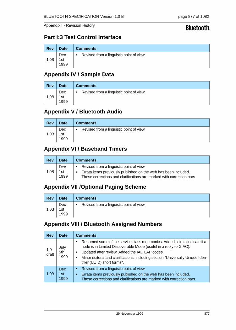
BLUETOOTH SPECIFICATION Version 1.0 B page 877 of 1082
Appendix I - Revision History
Part I:3 Test Control Interface
Appendix IV / Sample Data
Appendix V / Bluetooth Audio
Appendix VI / Baseband Timers
Appendix VII /Optional Paging Scheme
Appendix VIII / Bluetooth Assigned Numbers
Rev Date Comments
1.0BDec1st1999
• Revised from a linguistic point of view.
Rev Date Comments
1.0BDec1st1999
• Revised from a linguistic point of view.
Rev Date Comments
1.0BDec1st1999
• Revised from a linguistic point of view.
Rev Date Comments
1.0BDec1st1999
• Revised from a linguistic point of view.• Errata items previously published on the web has been included.
These corrections and clarifications are marked with correction bars.
Rev Date Comments
1.0BDec1st1999
• Revised from a linguistic point of view.
Rev Date Comments
1.0 draft
July 5th 1999
• Renamed some of the service class mnemonics. Added a bit to indicate if a node is in Limited Discoverable Mode (useful in a reply to GIAC).
• Updated after review. Added the IAC LAP codes.• Minor editoral and clarifications, including section "Universally Unique Iden-
tifier (UUID) short forms".
1.0BDec1st1999
• Revised from a linguistic point of view.• Errata items previously published on the web has been included.
These corrections and clarifications are marked with correction bars.
29 November 1999 877

BLUETOOTH SPECIFICATION Version 1.0 B page 878 of 1082
Appendix I - Revision History
Appendix IX / Message Sequence Charts
Rev Date Comments
1.0 draft
July 5th 1999
• Command and Parameter updated; Chapter 7 added; Local- and Remote Hold-Mode removed; Chapter 8 clarified; No HCI-Num-Completed-Pack-ets-Event in ACL- and SCO-Connection creation; LMP-feature-req/-res added in ACL-Connection-Setup; LMP-feature-req/-res removed in SCO-Connection-Setup
• MSC "Onetime-Inquiry" and "Periodic-Inquiry" clarified with additional ID-Packet;
• MSC "Local Loopback-Mode" exited with HCI_Write_Loopback_Mode instead with HCI_Reset;
• MSC "Remote Loopback-Mode" exited with HCI_Write_Loopback_Mode instead with HCI_Reset;
• MSC "Switch Role" updated with LMP_clkoffset_req/-res and LMP_slot_offset;
• Editorial changes;• MSC "Switch Role": subscenario 2 added; Modified as Toru's proposal;• MSC "ACL-Connection Request": slot-offset and clock-offset exchange
subscenario3;• Figure 4: no loopback to Page/Page-Res in case of Role-Switch;• LMP_features_req/-res: added in MSC "Pairing" and MSC "Authentica-
tion", removed in MSC "Encryption and Setup Complete";• MSC "Local Loopback Mode": two additional SCO-Connections added;
1.0BDec1st1999
• Revised from a linguistic point of view.• Errata items previously published on the web has been included.
These corrections and clarifications are marked with correction bars.The following figures are modified: 3.2, 3.3, 4.3 and 4.9
878 29 November 1999

Appendix II
CONTRIBUTORS

880 29 November 1999
BLUETOOTH SPECIFICATION Version 1.0 B page 880 of 1082
Appendix II - Contributors

BLUETOOTH SPECIFICATION Version 1.0 B page 881 of 1082
Appendix II - Contributors
Contributors
Part A / Radio Specification
Part B / Baseband Specification
Part C / Link Manager Protocol
Sven Mattisson Ericsson Mobile Communications AB
Lars Nord (owner) Ericsson Mobile Communications AB
Anders Svensson Ericsson Mobile Communications AB
Paul Burgess Nokia Mobile Phones
Olaf Joeressen Nokia Mobile Phones
Thomas Muller Nokia Mobile Phones
Troy Beukema IBM Corporation
Brian Gaucher IBM Corporation
Allen Huotari Toshiba Corporation
Ayse Findikli Ericsson Mobile Communications AB
Jaap Haartsen (owner) Ericsson Mobile Communications AB
Joakim Persson Ericsson Mobile Communications AB
Chatschik Bisdikian IBM Corp.
Kris Fleming Intel Corp.
Olaf Joeressen Nokia Mobile Phones
Thomas Muller Nokia Mobile Phones
Johannes Elg Ericsson Mobile Communications AB
Jaap Haartsen Ericsson Mobile Communications AB
Tobias Melin (owner) Ericsson Mobile Communications AB
Chatschik Bisdikian IBM Corporation
Kris Fleming Intel Corporation
Thomas Busse Nokia Mobile Phones
Olaf Joeressen Nokia Mobile Phones
Thomas Müller Nokia Mobile Phones
Dong Nguyen Nokia Mobile Phones
29 November 1999 881

BLUETOOTH SPECIFICATION Version 1.0 B page 882 of 1082
Appendix II - Contributors
Part DLogical Link Control and Adaptation Protocol Specification
Burgess, Jon 3COM
Moran, Paul 3COM
Elg, Johannes Ericsson Mobile Communications AB
Haartsen, Jaap Ericsson Mobile Communications AB
Nilsson, Ingemar Ericsson Mobile Communications AB
Runesson, Stefan Ericsson Mobile Communications AB
Slot, Gerrit Ericsson Mobile Communications AB
Sörensen, Johan Ericsson Mobile Communications AB
Svennarp, Goran Ericsson Mobile Communications AB
Aihara, Tohru IBM Corporation
Bisdikian, Chatschik IBM Corporation
Fleming, Kris Intel Corporation
Gadamsetty, Uma Intel Corporation
Hunter, Robert Intel Corporation
Inouye, Jon (owner) Intel Corporation
Lo, Steve C. Intel Corporation
Zhu, Chunrong Intel Corporation
Busse, Thomas Nokia Mobile Phones
Makinen, Rauno Nokia Mobile Phones
Müller, Thomas Nokia Mobile Phones
Nykänen, Petri Nokia Mobile Phones
Ollikainen, Peter Nokia Mobile Phones
Kinoshita, Katsuhiro Toshiba Corporation
882 29 November 1999

BLUETOOTH SPECIFICATION Version 1.0 B page 883 of 1082
Appendix II - Contributors
Part EService Discovery Protocol (SDP)
Part F:1RFCOMM with TS 07.10
Plasson, Ned 3Com
Avery, John Convergence
Kronz, Jason Convergence
Elg, Johannes Ericsson
Bisdikian, Chatschik IBM
Kermani, Parviz IBM
Miller, Brent IBM
Osterman, Dick IBM
Inouye, Jon Intel
Kambhatla, Srikanth Intel
Eaglstun, Jay Motorola
Farnsworth, Dale (owner) Motorola
Rosso, Jean-Michel Motorola
Grönholm, Jan Nokia
Müller, Thomas Nokia
Iwamura, Kazuaki Toshiba
Pascoe, Bob Xtraworx
Ingemar Nilsson Ericsson Mobile Communications AB
Patrik Olsson Ericsson Mobile Communications AB
Gerrit Slot Ericsson Mobile Communications AB
Johan Sörensen (owner) Ericsson Mobile Communications AB
Srikanth Kambhatla Intel Corporation
Michael Camp Nokia Mobile Phones
Riku Mettälä Nokia Mobile Phones
29 November 1999 883

BLUETOOTH SPECIFICATION Version 1.0 B page 884 of 1082
Appendix II - Contributors
Part F:2IrDA Interoperability
Part F:3Telephony Control Protocol Specification
David Kammer 3Com
Christian Andersson Ericsson Mobile Communications AB
Johannes Elg Ericsson Mobile Communications AB
Patrik Olsson Ericsson Mobile Communications AB
Johan Sörensen Ericsson Mobile Communications AB
Dave Suvak Extended Systems
Chatschik Bisdikian IBM
Brent Miller IBM
Apratim Purakayastha IBM
Aron Walker IBM
Jon Inouye Intel Corporation
Michael Camp Nokia Mobile Phones
Riku Mettälä (owner) Nokia Mobile Phones
Peter Ollikainen Nokia Mobile Phones
James Scales Nokia Mobile Phones
Steve Rybicki Puma Technology
John Stossel Puma Technology
Richard Shaw 3COM
Ken Morley 3COM
Olof Dellien Ericsson Mobile Communications AB
Gert-jan van Lieshout Ericsson Mobile Communications AB
Erik Slotboom (owner) Ericsson Mobile Communications AB
Shridar Rajagopal Intel Corporation
Ramu Ramakeshavan Intel Corporation
Brian Redding Motorola
Thomas Müller Nokia Mobile Phones
Christian Zechlin Nokia Mobile Phones
Jun'ichi Yoshizawa Toshiba Corporation
884 29 November 1999

BLUETOOTH SPECIFICATION Version 1.0 B page 885 of 1082
Appendix II - Contributors
Part F:4Interoperability Requirements for Bluetooth as a WAP Bearer
Part H:1Bluetooth Host Controller Interface Functional Specification
Johannes Elg Ericsson Mobile Communications AB
Robert Hed Ericsson Mobile Communications AB
Jon Inouye Intel Corporation
Michael T. Camp (owner) Nokia Mobile Phones
Riku Mettala Nokia Mobile Phones
Kevin Wagner Nokia Mobile Phones
Todor Cooklev 3Com Corporation
Johannes Elg Ericsson Mobile Communications AB
Christian Johansson Ericsson Mobile Communications AB
Patrik Lundin Ericsson Mobile Communications AB
Tobias Melin Ericsson Mobile Communications AB
Toru Aihara IBM Corporation
Chatschik Bisdikian IBM Corporation
Nathan Lee IBM Corporation
Akihiko Mizutani IBM Corporation
Les Cline Intel Corporation
Bailey Cross Intel Corporation
Kris Fleming (owner) Intel Corporation
Robert Hunter Intel Corporation
Jon Inouye Intel Corporation
Srikanth Kambhatla Intel Corporation
Steve Lo Intel Corporation
Vijay Suthar Intel Corporation
Greg Muchnik Motorola
Thomas Busse Nokia Mobile Phones
Thomas Muller Nokia Mobile Phones
Dong Nguyen Nokia Mobile Phones
Christian Zechlin Nokia Mobile Phones
Masahiro Tada Toshiba Corporation
29 November 1999 885

BLUETOOTH SPECIFICATION Version 1.0 B page 886 of 1082
Appendix II - Contributors
Part H:2 / HCI USB Transport Layer
Part H:3 / HCI RS232 Transport Layer
Part H:4 / HCI UART Transport Layer
Patrik Lundin Ericsson Mobile Communications AB
Nathan Lee IBM Corporation
Les Cline Intel Corporation
Brad Hosler Intel Corporation
John Howard Intel Corporation
Robert Hunter (owner) Intel Corporation
Srikanth Kambhatla Intel Corporation
Kosta Koeman Intel Corporation
John McGrath Intel Corporation
Uwe Gondrum Nokia Mobile Phone
Johannes Elg Ericsson Mobile Communications AB
Sven Jerlhagen Ericsson Mobile Communications AB
Patrik Lundin Ericsson Mobile Communications AB
Chatschik Bisdikian IBM Corporation
Edgar Kerstan IBM Corporation
Nathan Lee (owner) IBM Corporation
Robert Hunter Intel Corporation
Patrick Kane Motorola
Uwe Gondrum Nokia Mobile Phone
Masahiro Tada Toshiba Corporation
Johannes Elg Ericsson Mobile Communications AB
Sven Jerlhagen Ericsson Mobile Communications AB
Patrik Lundin (owner) Ericsson Mobile Communications AB
Lars Novak Ericsson Mobile Communications AB
Edgar Kerstan IBM Corporation
Nathan Lee IBM Corporation
Robert Hunter Intel Corporation
Patrick Kane Motorola
Uwe Gondrum Nokia Mobile Phone
Masahiro Tada Toshiba Corporation
886 29 November 1999

BLUETOOTH SPECIFICATION Version 1.0 B page 887 of 1082
Appendix II - Contributors
Part I:1 / Bluetooth Test Mode
Part I:2 / Bluetooth Compliance Requirements
Part I:3 / Bluetooth Test Control Interface
Appendix IV / Encryption Sample Data
Appendix V / Bluetooth Audio
Ayse Findikli Ericsson Mobile Communications AB
Mårten Mattsson Ericsson Mobile Communications AB
Tobias Melin Ericsson Mobile Communications AB
Lars Nord Ericsson Mobile Communications AB
Fredrik Töörn Ericsson Mobile Communications AB
Jeffrey Schiffer Intel Corporation
Daniel Bencak Nokia Mobile Phones
Arno Kefenbaum Nokia Mobile Phones
Thomas Müller (owner) Nokia Mobile Phones
Roland Schmale Nokia Mobile Phones
Lawrence Jones ComBit,Inc.
Magnus Hansson (owner) Ericsson Mobile Communications AB
Göran Svennarp Ericsson Mobile Communications AB
Gary Robinson IBM Corporation
John Webb Intel Corporation
Petri Morko Nokia Mobile Phones
Warren Allen Toshiba Corporation
Mårten Mattsson (owner) Ericsson Mobile Communications AB
Dan Sönnerstam Ericsson Mobile Communications AB
Thomas Müller Nokia Mobile Phones
Joakim Persson (owner) Ericsson Mobile Communications AB
Thomas Müller Nokia Mobile Phones
Thomas Sander Nokia Mobile Phones
Joakim Persson (owner) Ericsson Mobile Communication AB
Fisseha Mekuria Ericsson Mobile Communication AB
Magnus Hansson Ericsson Mobile Communication AB
Mats Omrin Ericsson Mobile Communication AB
29 November 1999 887

BLUETOOTH SPECIFICATION Version 1.0 B page 888 of 1082
Appendix II - Contributors
Appendix VI / Baseband Timers
Appendix VII / Optional Paging Scheme
Appendix VIII / Bluetooth Assigned Numbers
Appendix IX / Message Sequence Charts between
The Bluetooth Specification was compiled and edited by Dan Sonnerstam,Pyramid Communication AB
Ayse Findikli Ericsson Mobile Communications AB
Jaap Haartsen (owner) Ericsson Mobile Communications AB
Joakim Persson Ericsson Mobile Communications AB
Ayse Findikli Ericsson Mobile Communications AB
Jaap Haartsen (owner) Ericsson Mobile Communications AB
Joakim Persson Ericsson Mobile Communications AB
Olaf Joeressen Nokia Mobile Phones
Thomas Muller Nokia Mobile Phones
Markus Schetelig Nokia Mobile Phones
Johannes Elg (owner) Ericsson Mobile Communications AB
Numerous SIG members contributed directly or indirectly to this revision
Todor Cooklev 3Com Corporation
Christian Johansson Ericsson Mobile Communications AB
Tobias Melin Ericsson Mobile Communications AB
Toru Aihara IBM Corporation
Chatschik Bisdikian IBM Corporation
Nathan Lee IBM Corporation
Kris Fleming Intel Cop.
Greg Muchnik Motorola
Thomas Busse Nokia Mobile Phones
Dong Nguyen (owner) Nokia Mobile Phones
888 29 November 1999

Appendix III
ACRONYMSAND
ABBREVIATIONS

890 28 November 1999
BLUETOOTH SPECIFICATION Version 1.0 B page 890 of 1082
Appendix III - Acronyms

BLUETOOTH SPECIFICATION Version 1.0 B page 891 of 1082
Appendix III - Acronyms
List of Acronyms and Abbreviations
Acronym or abbreviation Writing out in full Which means
ACK Acknowledge
ACL linkAsynchronous Connection-Less link
Provides a packet-switched con-nection.(Master to any slave)
ACO Authenticated Ciphering Offset
AM_ADDR Active Member Address
AR_ADDR Access Request Address
ARQ Automatic Repeat reQuest
B
BB BaseBand
BCH Bose, Chaudhuri & HocquenghemType of code
The persons who discovered these codes in 1959 (H) and 1960 (B&C)
BD_ADDR Bluetooth Device Address
BER Bit Error Rate
BT Bandwidth Time
BT Bluetooth
C
CAC Channel Access Code
CC Call Control
CL Connectionless
CODEC COder DECoder
COF Ciphering Offset
CRC Cyclic Redundancy Check
CVSDContinuous Variable Slope Delta Modulation
D
DAC Device Access Code
DCE Data Communication Equipment
28 November 1999 891
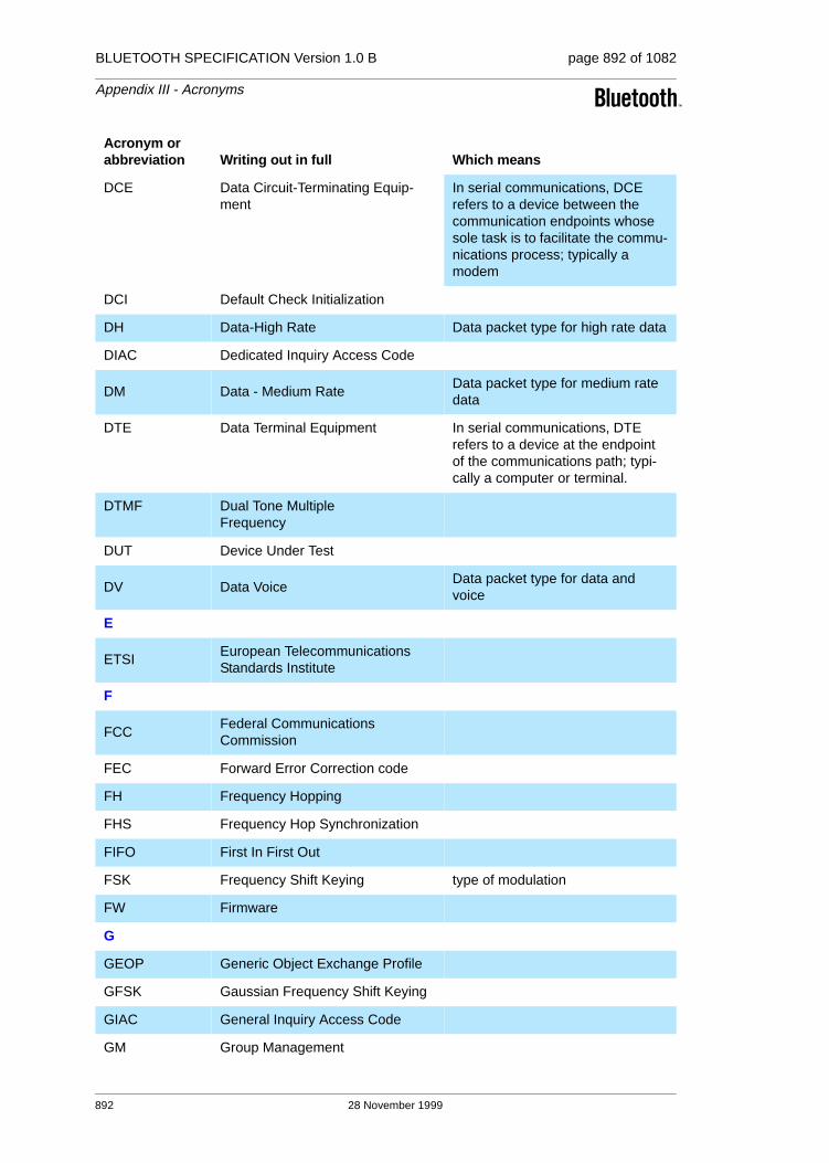
BLUETOOTH SPECIFICATION Version 1.0 B page 892 of 1082
Appendix III - Acronyms
DCE Data Circuit-Terminating Equip-ment
In serial communications, DCE refers to a device between the communication endpoints whose sole task is to facilitate the commu-nications process; typically a modem
DCI Default Check Initialization
DH Data-High Rate Data packet type for high rate data
DIAC Dedicated Inquiry Access Code
DM Data - Medium RateData packet type for medium rate data
DTE Data Terminal Equipment In serial communications, DTE refers to a device at the endpoint of the communications path; typi-cally a computer or terminal.
DTMF Dual Tone Multiple Frequency
DUT Device Under Test
DV Data VoiceData packet type for data and voice
E
ETSIEuropean Telecommunications Standards Institute
F
FCCFederal Communications Commission
FEC Forward Error Correction code
FH Frequency Hopping
FHS Frequency Hop Synchronization
FIFO First In First Out
FSK Frequency Shift Keying type of modulation
FW Firmware
G
GEOP Generic Object Exchange Profile
GFSK Gaussian Frequency Shift Keying
GIAC General Inquiry Access Code
GM Group Management
Acronym or abbreviation Writing out in full Which means
892 28 November 1999

BLUETOOTH SPECIFICATION Version 1.0 B page 893 of 1082
Appendix III - Acronyms
H
HA Host Application SW using Bluetooth
HCI Host Controller Interface
HEC Header-Error-Check
HID Human Interface Device
HV High quality Voice e.g. HV1 packet
HW Hardware
I
IAC Inquiry Access Code
IEEEInstitute of Electronic and Electrical Engineering
IETF Internet Engineering Task Force
IP Internet Protocol
IrDA Infra-red Data Association
IrMC Ir Mobile Communications
ISDN Integrated Services Digital Net-works
ISM Industrial, Scientific, Medical
IUT Implementation Under Tes
L
L_CH Logical Channel
L2CA Logical Link Control and Adaption Logical Link Control And Manage-ment part of the Bluetooth protocol stack
L2CAP Logical Link Control and Adaption Protocol
LAP Lower Address Part
LC Link Controller Link Controller (or baseband) part of the Bluetooth protocol stack
Low level Baseband protocol han-dler
LCP Link Control Protocol
LCSS Link Controller Service Signalling
LFSR Linear Feedback Shift Register
LM Link Manager
Acronym or abbreviation Writing out in full Which means
28 November 1999 893

BLUETOOTH SPECIFICATION Version 1.0 B page 894 of 1082
Appendix III - Acronyms
LMP Link Manager ProtocolFor LM peer to peer communica-tion
LSB Least Significant Bit
M
M Master or Mandatory
M_ADDR Medium Access Control Address
MAC Medium Access Control
MAPIMessaging Application Procedure Interface
MMI Man Machine Interface
MS Mobile Station
MS Multiplexing sublayer
MSB Most Significant Bit
MSC Message Sequence Chart
MTU Maximum Transmission Unit
MUX Multiplexing Sublayer a sublayer of the L2CAP layer
N
NAK Negative Acknowledge
NAP Non-significant Address Part
O
O Optional
OBEX OBject EXchange protocol
OCF Opcode Command Field
P
PCM Pulse Coded Modulation
PCMCIAPersonal Computer Memory Card International Association
PDU Protocol Data Unit a message
PIN Personal Identification Number
PM_ADDR Parked Member Address
PN Pseudo-random Noise
PnP Plug and Play
POTS Plain Old Telephone system
Acronym or abbreviation Writing out in full Which means
894 28 November 1999

BLUETOOTH SPECIFICATION Version 1.0 B page 895 of 1082
Appendix III - Acronyms
PPM Part Per Million
PPP Point-to-Point Protocol
PRBS Pseudo Random Bit Sequence
PRNG Pseudo Random Noise Generation
PSTNPublic Switched Telephone Net-work
Q
QoS Quality of Service
R
RAND Random number
RF Radio Frequency
RFC Request For Comments
RFCOMM Serial cable emulation protocol based on ETSI TS 07.10
RSSI Received Signal Strength Indica-tion
RX Receiver
S
S Slave
SAP Service Access Points
SAR Segmentation and Reassembly
SCO link Synchronous Connection-Ori-ented link
Supports time-bounded informa-tion like voice.(Master to single slave)
SD Service Discovery
SDDB Service Discovery Database
SDP Service Discovery Protocol
SEQN Sequential Numbering scheme
SRES Signed Response
SS Supplementary Services
SSI Signal Strength Indication
SUT System Under Test
SW Software
Acronym or abbreviation Writing out in full Which means
28 November 1999 895
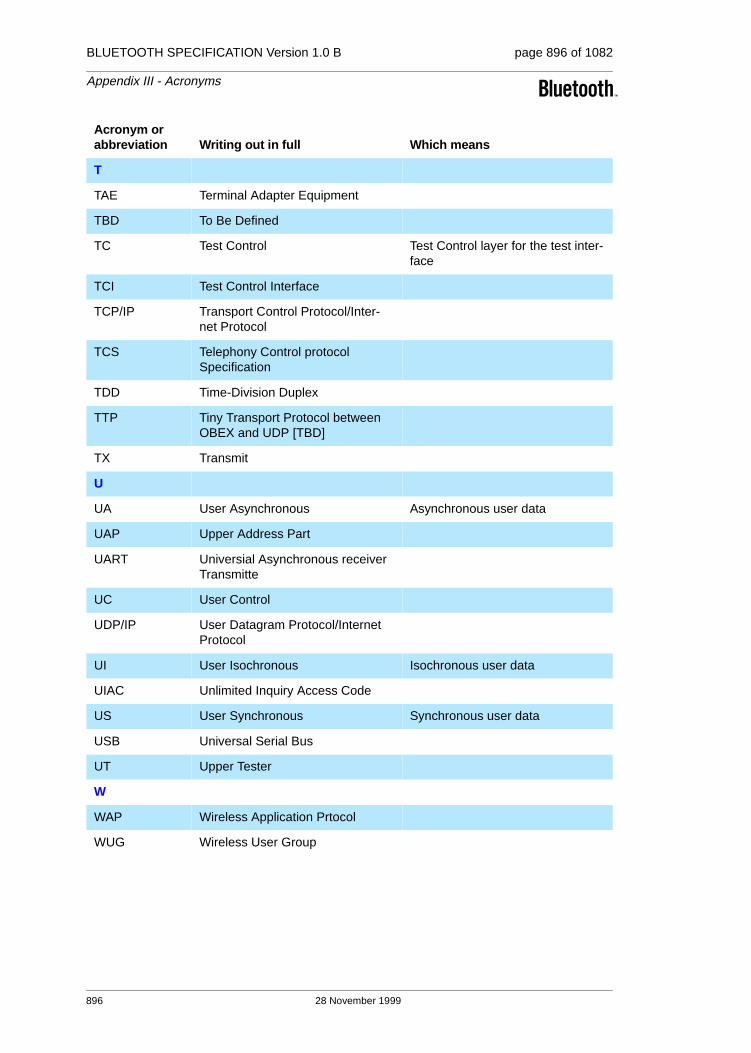
BLUETOOTH SPECIFICATION Version 1.0 B page 896 of 1082
Appendix III - Acronyms
T
TAE Terminal Adapter Equipment
TBD To Be Defined
TC Test Control Test Control layer for the test inter-face
TCI Test Control Interface
TCP/IP Transport Control Protocol/Inter-net Protocol
TCS Telephony Control protocol Specification
TDD Time-Division Duplex
TTP Tiny Transport Protocol between OBEX and UDP [TBD]
TX Transmit
U
UA User Asynchronous Asynchronous user data
UAP Upper Address Part
UART Universial Asynchronous receiver Transmitte
UC User Control
UDP/IP User Datagram Protocol/Internet Protocol
UI User Isochronous Isochronous user data
UIAC Unlimited Inquiry Access Code
US User Synchronous Synchronous user data
USB Universal Serial Bus
UT Upper Tester
W
WAP Wireless Application Prtocol
WUG Wireless User Group
Acronym or abbreviation Writing out in full Which means
896 28 November 1999
BLUETOOTH SPECIFICATION Version 1.0 B page 897 of 1082
Appendix III - Acronyms
Definitions
Baseband. The Bluetooth baseband specifies the medium access and physi-cal layers procedures to support the exchange of real-time voice and data information streams and ad-hoc networking between Bluetooth units.
Coverage area . The area where two Bluetooth units can exchange mes-sages with acceptable quality and performance.
Host Terminal interface. Host terminal interface is the Interface between Bluetooth Host and Bluetooth Unit.
Inquiry. A Bluetooth unit transmits inquiry messages in order to discover the other Bluetooth units that are active within the coverage area. The Bluetooth units that capture inquiry messages may send a response to the inquiring Bluetooth unit. The response contains information about the Bluetooth unit itself and its Bluetooth Host.
Isochronous user channel . Channel used for time bounded information like i.e. compressed audio (ACL link).
Logical Channel. The different types of channels on a Physical Link.
Bluetooth Host. Bluetooth Host is a computing device, peripheral, cellular telephone, access point to PSTN network, etc. A Bluetooth Host attached to a Bluetooth unit may communicate with other Bluetooth Hosts attached to their Bluetooth units as well. The communication channel through the Bluetooth units provides almost wire-like transparency.
Bluetooth Unit. Bluetooth Unit is a voice/data circuit equipment for a short-range wireless communication link. It allows voice and data communications between Bluetooth Hosts.
Bluetooth. Bluetooth is a wireless communication link, operating in the unli-censed ISM band at 2,4 GHz using a frequency hopping tranceiver. It allows real-time voice and data communications between Bluetooth Hosts. The link protocol is based on time slots.
Packet. Format of aggregated bits that can be transmitted in 1, 3, or 5 time slots.
Paging. An Bluetooth unit transmits paging messages in order to set up a communication link to another Bluetooth unit who is active within the cover-age area.
28 November 1999 897

BLUETOOTH SPECIFICATION Version 1.0 B page 898 of 1082
Appendix III - Acronyms
Physical Channel. Synchronized RF hopping sequence in a piconet
Physical Link. Connection between devices.
Piconet. In the Bluetooth system, the channel is shared among several Blue-tooth units. The units sharing a common channel constitute a piconet.
RFCOMM Client. An RFCOMM client is an application that requests a con-nection to another application (RFCOMM server).
RFCOMM initiator. The device initiating the RFCOMM session, i.e.setting up RFCOMM channel on L2CAP and starting RFCOMM multiplexing with the SABM command on DLCI 0 (zero).
RFCOMM Server. An RFCOMM server is an application that awaits a con-nection from an RFCOMM client on another device. What happens after such a connection is established is out of scope of this definition.
RFCOMM Server Channel. This is a subfield of the TS 07.10 DLCI number. This abstraction is used to allow both server and client applications to reside on both sides of an RFCOMM session.
Service Discovery. The ability to discover the capability of connecting devices or hosts
Scatternet. Two or more piconets co-located in the same area (with or witout inter-piconet communication).
Time Slot. The Physical Channel is divided into 625 µs long time slots.
898 28 November 1999

Appendix IV
SAMPLE DATA
This appendix contains sample data for various parts of the Bluetooth baseband spec-ification. All sample data are provided for reference purpose only; they are intended as a complement to the definitions provided else-where in the specification. They can be used to check the behavior of an implementation and avoid misunderstandings. Fulfilling these sample data is a necessary but not sufficient condition for an implementation to be fully Bluetooth compliant.

BLUETOOTH SPECIFICATION Version 1.0 B page 900 of 1082
Appendix IV - Sample Data
900 29 November 1999

BLUETOOTH SPECIFICATION Version 1.0 B page 901 of 1082
Appendix IV - Sample Data
CONTENTS
1 Encryption Sample Data ..................................................................9021.1 Generating Kc’ from Kc, ...........................................................9021.2 First Set of Sample Data..........................................................9051.3 Second Set of Sample Data.....................................................9131.4 Third Set of Samples................................................................9211.5 Fourth Set of Samples .............................................................929
2 Frequency Hopping Sample Data—Mandatory Scheme ..............9372.1 The 79-hop System Sample Data............................................937
2.1.1 First set........................................................................938
2.1.2 Second set ..................................................................940
2.1.3 Third set ......................................................................942
2.2 The 23-hop System Sample Data............................................9432.2.1 First set........................................................................943
2.2.2 Second set ..................................................................946
2.2.3 Third set ......................................................................948
3 Access Code Sample Data ..............................................................950
4 HEC and Packet Header Sample Data............................................953
5 CRC Sample Data.............................................................................954
6 Complete Sample Packets...............................................................9556.1 Example of DH1 Packet...........................................................9556.2 Example of DM1 Packet...........................................................956
7 Whitening Sequence Sample Data .................................................957
8 FEC Sample Data..............................................................................960
9 Encryption Key Sample Data ..........................................................9619.1 Four Tests of E1.......................................................................9619.2 Four Tests of E21.....................................................................9659.3 Three Tests of E22...................................................................9689.4 Tests of E22 With Pin Augmenting...........................................9709.5 Four Tests of E3.......................................................................980
29 November 1999 901

BLUETOOTH SPECIFICATION Version 1.0 B page 902 of 1082
Appendix IV - Sample Data
1 ENCRYPTION SAMPLE DATA
This part consist of four sets of sample data for the encryption process.
With respect to the functional description of the encryption engine in the Blue-tooth baseband specification, the contents of registers and resulting concurrent values are listed as well. This by no means excludes different implementations (as far as they produce the same encryption stream) but is intended to describe the functional behavior.
In case of misunderstandings or inconsistencies, these sample data form the normative reference.
1.1 GENERATING KC’ FROM KC,
where Kc’(x) = g2(x)(Kc(x) mod g1(x)).
Note: All polynomials are in hexadecimal notation.
’L’ is the effective key length in bytes.
The notation ’p: [m]’ implies that deg(p(x)) = m.
MSB LSB
L = 1
g1: [8] 00000000 00000000 00000000 0000011d
g2: [119] 00e275a0 abd218d4 cf928b9b bf6cb08f
Kc: a2b230a4 93f281bb 61a85b82 a9d4a30e
Kc mod g1: [7] 00000000 00000000 00000000 0000009f
g2(Kc mod g1): [126] 7aa16f39 59836ba3 22049a7b 87f1d8a5
-----------------------------------------------------------
L = 2
g1: [16] 00000000 00000000 00000000 0001003f
g2: [112] 0001e3f6 3d7659b3 7f18c258 cff6efef
Kc: 64e7df78 bb7ccaa4 61433123 5b3222ad
Kc mod g1: [12] 00000000 00000000 00000000 00001ff0
g2(Kc mod g1): [124] 142057bb 0bceac4c 58bd142e 1e710a50
-----------------------------------------------------------
L = 3
g1: [24] 00000000 00000000 00000000 010000db
g2: [104] 000001be f66c6c3a b1030a5a 1919808b
Kc: 575e5156 ba685dc6 112124ac edb2c179
Kc mod g1: [23] 00000000 00000000 00000000 008ddbc8
g2(Kc mod g1): [127] d56d0adb 8216cb39 7fe3c591 1ff95618
-----------------------------------------------------------
L = 4
g1: [32] 00000000 00000000 00000001 000000af
g2: [96] 00000001 6ab89969 de17467f d3736ad9
Kc: 8917b4fc 403b6db2 1596b86d 1cb8adab
Kc mod g1: [31] 00000000 00000000 00000000 aa1e78aa
g2(Kc mod g1): [127] 91910128 b0e2f5ed a132a03e af3d8cda
-----------------------------------------------------------
902 29 November 1999 Encryption Sample Data

BLUETOOTH SPECIFICATION Version 1.0 B page 903 of 1082
Appendix IV - Sample Data
L = 5
g1: [40] 00000000 00000000 00000100 00000039
g2: [88] 00000000 01630632 91da50ec 55715247
Kc: 785c915b dd25b9c6 0102ab00 b6cd2a68
Kc mod g1: [38] 00000000 00000000 0000007f 13d44436
g2(Kc mod g1): [126] 6fb5651c cb80c8d7 ea1ee56d f1ec5d02
-----------------------------------------------------------
L = 6
g1: [48] 00000000 00000000 00010000 00000291
g2: [77] 00000000 00002c93 52aa6cc0 54468311
Kc: 5e77d19f 55ccd7d5 798f9a32 3b83e5d8
Kc mod g1: [47] 00000000 00000000 000082eb 4af213ed
g2(Kc mod g1): [124] 16096bcb afcf8def 1d226a1b 4d3f9a3d
-----------------------------------------------------------
Encryption Sample Data 29 November 1999 903

BLUETOOTH SPECIFICATION Version 1.0 B page 904 of 1082
Appendix IV - Sample Data
L = 7
g1: [56] 00000000 00000000 01000000 00000095
g2: [71] 00000000 000000b3 f7fffce2 79f3a073
Kc: 05454e03 8ddcfbe3 ed024b2d 92b7f54c
Kc mod g1: [55] 00000000 00000000 0095b8a4 8eb816da
g2(Kc mod g1): [126] 50f9c0d4 e3178da9 4a09fe0d 34f67b0e
-----------------------------------------------------------
L = 8
g1: [64] 00000000 00000001 00000000 0000001b
g2: [63] 00000000 00000000 a1ab815b c7ec8025
Kc: 7ce149fc f4b38ad7 2a5d8a41 eb15ba31
Kc mod g1: [63] 00000000 00000000 8660806c 1865deec
g2(Kc mod g1): [126] 532c36d4 5d0954e0 922989b6 826f78dc
-----------------------------------------------------------
L = 9
g1: [72] 00000000 00000100 00000000 00000609
g2: [49] 00000000 00000000 0002c980 11d8b04d
Kc: 5eeff7ca 84fc2782 9c051726 3df6f36e
Kc mod g1: [71] 00000000 00000083 58ccb7d0 b95d3c71
g2(Kc mod g1): [120] 016313f6 0d3771cf 7f8e4bb9 4aa6827d
-----------------------------------------------------------
L = 10
g1: [80] 00000000 00010000 00000000 00000215
g2: [42] 00000000 00000000 0000058e 24f9a4bb
Kc: 7b13846e 88beb4de 34e7160a fd44dc65
Kc mod g1: [79] 00000000 0000b4de 34171767 f36981c3
g2(Kc mod g1): [121] 023bc1ec 34a0029e f798dcfb 618ba58d
-----------------------------------------------------------
L = 11
g1: [88] 00000000 01000000 00000000 0000013b
g2: [35] 00000000 00000000 0000000c a76024d7
Kc: bda6de6c 6e7d757e 8dfe2d49 9a181193
Kc mod g1: [86] 00000000 007d757e 8dfe88aa 2fcee371
g2(Kc mod g1): [121] 022e08a9 3aa51d8d 2f93fa78 85cc1f87
-----------------------------------------------------------
L = 12
g1: [96] 00000001 00000000 00000000 000000dd
g2: [28] 00000000 00000000 00000000 1c9c26b9
Kc: e6483b1c 2cdb1040 9a658f97 c4efd90d
Kc mod g1: [93] 00000000 2cdb1040 9a658fd7 5b562e41
g2(Kc mod g1): [121] 030d752b 216fe29b b880275c d7e6f6f9
-----------------------------------------------------------
L = 13
g1: [104] 00000100 00000000 00000000 0000049d
g2: [21] 00000000 00000000 00000000 0026d9e3
Kc: d79d281d a2266847 6b223c46 dc0ab9ee
Kc mod g1: [100] 0000001d a2266847 6b223c45 e1fc5fa6
g2(Kc mod g1): [121] 03f11138 9cebf919 00b93808 4ac158aa
-----------------------------------------------------------
904 29 November 1999 Encryption Sample Data
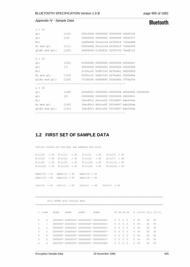
BLUETOOTH SPECIFICATION Version 1.0 B page 905 of 1082
Appendix IV - Sample Data
L = 14
g1: [112] 00010000 00000000 00000000 0000014f
g2: [14] 00000000 00000000 00000000 00004377
Kc: cad9a65b 9fca1c1d a2320fcf 7c4ae48e
Kc mod g1: [111] 0000a65b 9fca1c1d a2320fcf 7cb6a909
g2(Kc mod g1): [125] 284840fd f1305f3c 529f5703 76adf7cf
-----------------------------------------------------------
L = 15
g1: [120] 01000000 00000000 00000000 000000e7
g2: [7] 00000000 00000000 00000000 00000089
Kc: 21f0cc31 049b7163 d375e9e1 06029809
Kc mod g1: [119] 00f0cc31 049b7163 d375e9e1 0602840e
g2(Kc mod g1): [126] 7f10b53b 6df84b94 f22e566a 3754a37e
-----------------------------------------------------------
L = 16
g1: [128] 00000001 00000000 00000000 00000000 00000000
g2: [0] 00000000 00000000 00000000 00000001
Kc: 35ec8fc3 d50ccd32 5f2fd907 bde206de
Kc mod g1: [125] 35ec8fc3 d50ccd32 5f2fd907 bde206de
g2(Kc mod g1): [125] 35ec8fc3 d50ccd32 5f2fd907 bde206de
-----------------------------------------------------------
1.2 FIRST SET OF SAMPLE DATA
Initial values for the key, pan address and clock
K’c1[0] = 00 K’c1[1] = 00 K’c1[2] = 00 K’c1[3] = 00
K’c1[4] = 00 K’c1[5] = 00 K’c1[6] = 00 K’c1[7] = 00
K’c1[8] = 00 K’c1[9] = 00 K’c1[10] = 00 K’c1[11] = 00
K’c1[12] = 00 K’c1[13] = 00 K’c1[14] = 00 K’c1[15] = 00
Addr1[0] = 00 Addr1[1] = 00 Addr1[2] = 00
Addr1[3] = 00 Addr1[4] = 00 Addr1[5] = 00
Clk1[0] = 00 Clk1[1] = 00 Clk1[2] = 00 Clk1[3] = 00
===============================================================================================
Fill LFSRs with initial data
===============================================================================================
t clk# LFSR1 LFSR2 LFSR3 LFSR4 X1 X2 X3 X4 Z C[t+1] C[t] C[t-1]
0 0 0000000* 00000000* 000000000* 0000000000* 0 0 0 0 0 00 00 00
1 1 0000000* 00000001* 000000000* 0000000001* 0 0 0 0 0 00 00 00
2 2 0000000* 00000002* 000000000* 0000000003* 0 0 0 0 0 00 00 00
3 3 0000000* 00000004* 000000000* 0000000007* 0 0 0 0 0 00 00 00
4 4 0000000* 00000008* 000000000* 000000000E* 0 0 0 0 0 00 00 00
5 5 0000000* 00000010* 000000000* 000000001C* 0 0 0 0 0 00 00 00
6 6 0000000* 00000020* 000000000* 0000000038* 0 0 0 0 0 00 00 00
Encryption Sample Data 29 November 1999 905
BLUETOOTH SPECIFICATION Version 1.0 B page 906 of 1082
Appendix IV - Sample Data
7 7 0000000* 00000040* 000000000* 0000000070* 0 0 0 0 0 00 00 00
8 8 0000000* 00000080* 000000000* 00000000E0* 0 0 0 0 0 00 00 00
9 9 0000000* 00000100* 000000000* 00000001C0* 0 0 0 0 0 00 00 00
10 10 0000000* 00000200* 000000000* 0000000380* 0 0 0 0 0 00 00 00
11 11 0000000* 00000400* 000000000* 0000000700* 0 0 0 0 0 00 00 00
12 12 0000000* 00000800* 000000000* 0000000E00* 0 0 0 0 0 00 00 00
13 13 0000000* 00001000* 000000000* 0000001C00* 0 0 0 0 0 00 00 00
14 14 0000000* 00002000* 000000000* 0000003800* 0 0 0 0 0 00 00 00
15 15 0000000* 00004000* 000000000* 0000007000* 0 0 0 0 0 00 00 00
16 16 0000000* 00008000* 000000000* 000000E000* 0 0 0 0 0 00 00 00
17 17 0000000* 00010000* 000000000* 000001C000* 0 0 0 0 0 00 00 00
18 18 0000000* 00020000* 000000000* 0000038000* 0 0 0 0 0 00 00 00
19 19 0000000* 00040000* 000000000* 0000070000* 0 0 0 0 0 00 00 00
20 20 0000000* 00080000* 000000000* 00000E0000* 0 0 0 0 0 00 00 00
21 21 0000000* 00100000* 000000000* 00001C0000* 0 0 0 0 0 00 00 00
22 22 0000000* 00200000* 000000000* 0000380000* 0 0 0 0 0 00 00 00
23 23 0000000* 00400000* 000000000* 0000700000* 0 0 0 0 0 00 00 00
24 24 0000000* 00800000* 000000000* 0000E00000* 0 1 0 0 1 00 00 00
25 25 0000000* 01000000* 000000000* 0001C00000* 0 0 0 0 0 00 00 00
26 26 0000000 02000000* 000000000* 0003800000* 0 0 0 0 0 00 00 00
27 27 0000000 04000000* 000000000* 0007000000* 0 0 0 0 0 00 00 00
28 28 0000000 08000000* 000000000* 000E000000* 0 0 0 0 0 00 00 00
29 29 0000000 10000000* 000000000* 001C000000* 0 0 0 0 0 00 00 00
30 30 0000000 20000000* 000000000* 0038000000* 0 0 0 0 0 00 00 00
31 31 0000000 40000000* 000000000* 0070000000* 0 0 0 0 0 00 00 00
32 32 0000000 00000001 000000000* 00E0000000* 0 0 0 1 1 00 00 00
33 33 0000000 00000002 000000000* 01C0000000* 0 0 0 1 1 00 00 00
34 34 0000000 00000004 000000000 0380000000* 0 0 0 1 1 00 00 00
35 35 0000000 00000008 000000000 0700000000* 0 0 0 0 0 00 00 00
36 36 0000000 00000010 000000000 0E00000000* 0 0 0 0 0 00 00 00
37 37 0000000 00000020 000000000 1C00000000* 0 0 0 0 0 00 00 00
38 38 0000000 00000040 000000000 3800000000* 0 0 0 0 0 00 00 00
39 39 0000000 00000080 000000000 7000000000* 0 0 0 0 0 00 00 00
===============================================================================================
Start clocking Summation Combiner
===============================================================================================
40 1 0000000 00000100 000000000 6000000001 0 0 0 0 0 00 00 00
41 2 0000000 00000200 000000000 4000000003 0 0 0 0 0 00 00 00
42 3 0000000 00000400 000000000 0000000007 0 0 0 0 0 00 00 00
43 4 0000000 00000800 000000000 000000000E 0 0 0 0 0 00 00 00
44 5 0000000 00001001 000000000 000000001D 0 0 0 0 0 00 00 00
45 6 0000000 00002002 000000000 000000003B 0 0 0 0 0 00 00 00
46 7 0000000 00004004 000000000 0000000077 0 0 0 0 0 00 00 00
47 8 0000000 00008008 000000000 00000000EE 0 0 0 0 0 00 00 00
48 9 0000000 00010011 000000000 00000001DD 0 0 0 0 0 00 00 00
49 10 0000000 00020022 000000000 00000003BB 0 0 0 0 0 00 00 00
50 11 0000000 00040044 000000000 0000000777 0 0 0 0 0 00 00 00
51 12 0000000 00080088 000000000 0000000EEE 0 0 0 0 0 00 00 00
52 13 0000000 00100110 000000000 0000001DDD 0 0 0 0 0 00 00 00
53 14 0000000 00200220 000000000 0000003BBB 0 0 0 0 0 00 00 00
54 15 0000000 00400440 000000000 0000007777 0 0 0 0 0 00 00 00
55 16 0000000 00800880 000000000 000000EEEE 0 1 0 0 1 00 00 00
56 17 0000000 01001100 000000000 000001DDDD 0 0 0 0 0 00 00 00
57 18 0000000 02002200 000000000 000003BBBB 0 0 0 0 0 00 00 00
58 19 0000000 04004400 000000000 0000077777 0 0 0 0 0 00 00 00
59 20 0000000 08008800 000000000 00000EEEEE 0 0 0 0 0 00 00 00
60 21 0000000 10011000 000000000 00001DDDDD 0 0 0 0 0 00 00 00
906 29 November 1999 Encryption Sample Data

BLUETOOTH SPECIFICATION Version 1.0 B page 907 of 1082
Appendix IV - Sample Data
61 22 0000000 20022000 000000000 00003BBBBB 0 0 0 0 0 00 00 00
62 23 0000000 40044000 000000000 0000777777 0 0 0 0 0 00 00 00
63 24 0000000 00088001 000000000 0000EEEEEE 0 0 0 0 0 00 00 00
64 25 0000000 00110003 000000000 0001DDDDDD 0 0 0 0 0 00 00 00
65 26 0000000 00220006 000000000 0003BBBBBB 0 0 0 0 0 00 00 00
66 27 0000000 0044000C 000000000 0007777777 0 0 0 0 0 00 00 00
67 28 0000000 00880018 000000000 000EEEEEEE 0 1 0 0 1 00 00 00
68 29 0000000 01100031 000000000 001DDDDDDC 0 0 0 0 0 00 00 00
69 30 0000000 02200062 000000000 003BBBBBB8 0 0 0 0 0 00 00 00
70 31 0000000 044000C4 000000000 0077777770 0 0 0 0 0 00 00 00
71 32 0000000 08800188 000000000 00EEEEEEE0 0 1 0 1 0 01 00 00
72 33 0000000 11000311 000000000 01DDDDDDC1 0 0 0 1 0 00 01 00
73 34 0000000 22000622 000000000 03BBBBBB83 0 0 0 1 1 11 00 01
74 35 0000000 44000C44 000000000 0777777707 0 0 0 0 1 10 11 00
75 36 0000000 08001888 000000000 0EEEEEEE0E 0 0 0 1 1 01 10 11
76 37 0000000 10003111 000000000 1DDDDDDC1D 0 0 0 1 0 01 01 10
77 38 0000000 20006222 000000000 3BBBBBB83B 0 0 0 1 0 11 01 01
78 39 0000000 4000C444 000000000 7777777077 0 0 0 0 1 01 11 01
79 40 0000000 00018888 000000000 6EEEEEE0EF 0 0 0 1 0 10 01 11
80 41 0000000 00031110 000000000 5DDDDDC1DE 0 0 0 1 1 00 10 01
81 42 0000000 00062220 000000000 3BBBBB83BC 0 0 0 1 1 01 00 10
82 43 0000000 000C4440 000000000 7777770779 0 0 0 0 1 01 01 00
83 44 0000000 00188880 000000000 6EEEEE0EF2 0 0 0 1 0 11 01 01
84 45 0000000 00311100 000000000 5DDDDC1DE5 0 0 0 1 0 10 11 01
85 46 0000000 00622200 000000000 3BBBB83BCB 0 0 0 1 1 01 10 11
86 47 0000000 00C44400 000000000 7777707797 0 1 0 0 0 01 01 10
87 48 0000000 01888801 000000000 6EEEE0EF2F 0 1 0 1 1 11 01 01
88 49 0000000 03111003 000000000 5DDDC1DE5E 0 0 0 1 0 10 11 01
89 50 0000000 06222006 000000000 3BBB83BCBC 0 0 0 1 1 01 10 11
90 51 0000000 0C44400C 000000000 7777077979 0 0 0 0 1 00 01 10
91 52 0000000 18888018 000000000 6EEE0EF2F2 0 1 0 1 0 10 00 01
92 53 0000000 31110030 000000000 5DDC1DE5E5 0 0 0 1 1 11 10 00
93 54 0000000 62220060 000000000 3BB83BCBCB 0 0 0 1 0 00 11 10
94 55 0000000 444400C1 000000000 7770779797 0 0 0 0 0 10 00 11
95 56 0000000 08880183 000000000 6EE0EF2F2F 0 1 0 1 0 00 10 00
96 57 0000000 11100307 000000000 5DC1DE5E5F 0 0 0 1 1 01 00 10
97 58 0000000 2220060E 000000000 3B83BCBCBF 0 0 0 1 0 00 01 00
98 59 0000000 44400C1C 000000000 770779797E 0 0 0 0 0 11 00 01
99 60 0000000 08801838 000000000 6E0EF2F2FC 0 1 0 0 0 01 11 00
100 61 0000000 11003070 000000000 5C1DE5E5F8 0 0 0 0 1 11 01 11
101 62 0000000 220060E0 000000000 383BCBCBF0 0 0 0 0 1 01 11 01
102 63 0000000 4400C1C0 000000000 70779797E0 0 0 0 0 1 11 01 11
103 64 0000000 08018380 000000000 60EF2F2FC1 0 0 0 1 0 10 11 01
104 65 0000000 10030701 000000000 41DE5E5F82 0 0 0 1 1 01 10 11
105 66 0000000 20060E02 000000000 03BCBCBF04 0 0 0 1 0 01 01 10
106 67 0000000 400C1C05 000000000 0779797E09 0 0 0 0 1 10 01 01
107 68 0000000 0018380A 000000000 0EF2F2FC12 0 0 0 1 1 00 10 01
108 69 0000000 00307015 000000000 1DE5E5F825 0 0 0 1 1 01 00 10
109 70 0000000 0060E02A 000000000 3BCBCBF04B 0 0 0 1 0 00 01 00
110 71 0000000 00C1C055 000000000 779797E097 0 1 0 1 0 10 00 01
111 72 0000000 018380AA 000000000 6F2F2FC12F 0 1 0 0 1 11 10 00
112 73 0000000 03070154 000000000 5E5E5F825E 0 0 0 0 1 11 11 10
113 74 0000000 060E02A8 000000000 3CBCBF04BC 0 0 0 1 0 11 11 11
114 75 0000000 0C1C0550 000000000 79797E0979 0 0 0 0 1 00 11 11
115 76 0000000 18380AA0 000000000 72F2FC12F2 0 0 0 1 1 10 00 11
116 77 0000000 30701541 000000000 65E5F825E5 0 0 0 1 1 11 10 00
117 78 0000000 60E02A82 000000000 4BCBF04BCB 0 1 0 1 1 00 11 10
Encryption Sample Data 29 November 1999 907

BLUETOOTH SPECIFICATION Version 1.0 B page 908 of 1082
Appendix IV - Sample Data
118 79 0000000 41C05505 000000000 1797E09796 0 1 0 1 0 11 00 11
119 80 0000000 0380AA0A 000000000 2F2FC12F2C 0 1 0 0 0 01 11 00
120 81 0000000 07015415 000000000 5E5F825E59 0 0 0 0 1 11 01 11
121 82 0000000 0E02A82A 000000000 3CBF04BCB2 0 0 0 1 0 10 11 01
122 83 0000000 1C055054 000000000 797E097964 0 0 0 0 0 01 10 11
123 84 0000000 380AA0A8 000000000 72FC12F2C9 0 0 0 1 0 01 01 10
124 85 0000000 70154151 000000000 65F825E593 0 0 0 1 0 11 01 01
125 86 0000000 602A82A3 000000000 4BF04BCB26 0 0 0 1 0 10 11 01
126 87 0000000 40550546 000000000 17E097964C 0 0 0 1 1 01 10 11
127 88 0000000 00AA0A8D 000000000 2FC12F2C99 0 1 0 1 1 01 01 10
128 89 0000000 0154151A 000000000 5F825E5932 0 0 0 1 0 11 01 01
129 90 0000000 02A82A34 000000000 3F04BCB264 0 1 0 0 0 10 11 01
130 91 0000000 05505468 000000000 7E097964C9 0 0 0 0 0 01 10 11
131 92 0000000 0AA0A8D0 000000000 7C12F2C992 0 1 0 0 0 01 01 10
132 93 0000000 154151A1 000000000 7825E59324 0 0 0 0 1 10 01 01
133 94 0000000 2A82A342 000000000 704BCB2648 0 1 0 0 1 00 10 01
134 95 0000000 55054684 000000000 6097964C91 0 0 0 1 1 01 00 10
135 96 0000000 2A0A8D09 000000000 412F2C9923 0 0 0 0 1 01 01 00
136 97 0000000 54151A12 000000000 025E593246 0 0 0 0 1 10 01 01
137 98 0000000 282A3424 000000000 04BCB2648D 0 0 0 1 1 00 10 01
138 99 0000000 50546848 000000000 097964C91A 0 0 0 0 0 01 00 10
139 100 0000000 20A8D090 000000000 12F2C99235 0 1 0 1 1 00 01 00
140 101 0000000 4151A120 000000000 25E593246A 0 0 0 1 1 11 00 01
141 102 0000000 02A34240 000000000 4BCB2648D5 0 1 0 1 1 01 11 00
142 103 0000000 05468481 000000000 17964C91AB 0 0 0 1 0 10 01 11
143 104 0000000 0A8D0903 000000000 2F2C992357 0 1 0 0 1 00 10 01
144 105 0000000 151A1206 000000000 5E593246AE 0 0 0 0 0 01 00 10
145 106 0000000 2A34240C 000000000 3CB2648D5C 0 0 0 1 0 00 01 00
146 107 0000000 54684818 000000000 7964C91AB8 0 0 0 0 0 11 00 01
147 108 0000000 28D09030 000000000 72C9923571 0 1 0 1 1 01 11 00
148 109 0000000 51A12060 000000000 6593246AE2 0 1 0 1 1 10 01 11
149 110 0000000 234240C0 000000000 4B2648D5C5 0 0 0 0 0 00 10 01
150 111 0000000 46848180 000000000 164C91AB8A 0 1 0 0 1 01 00 10
151 112 0000000 0D090301 000000000 2C99235714 0 0 0 1 0 00 01 00
152 113 0000000 1A120602 000000000 593246AE28 0 0 0 0 0 11 00 01
153 114 0000000 34240C04 000000000 32648D5C51 0 0 0 0 1 10 11 00
154 115 0000000 68481809 000000000 64C91AB8A2 0 0 0 1 1 01 10 11
155 116 0000000 50903012 000000000 4992357144 0 1 0 1 1 01 01 10
156 117 0000000 21206024 000000000 13246AE288 0 0 0 0 1 10 01 01
157 118 0000000 4240C048 000000000 2648D5C511 0 0 0 0 0 00 10 01
158 119 0000000 04818090 000000000 4C91AB8A23 0 1 0 1 0 00 00 10
159 120 0000000 09030120 000000000 1923571446 0 0 0 0 0 00 00 00
160 121 0000000 12060240 000000000 3246AE288D 0 0 0 0 0 00 00 00
161 122 0000000 240C0480 000000000 648D5C511B 0 0 0 1 1 00 00 00
162 123 0000000 48180900 000000000 491AB8A237 0 0 0 0 0 00 00 00
163 124 0000000 10301200 000000000 123571446F 0 0 0 0 0 00 00 00
164 125 0000000 20602400 000000000 246AE288DF 0 0 0 0 0 00 00 00
165 126 0000000 40C04800 000000000 48D5C511BE 0 1 0 1 0 01 00 00
166 127 0000000 01809001 000000000 11AB8A237D 0 1 0 1 1 00 01 00
167 128 0000000 03012002 000000000 23571446FA 0 0 0 0 0 11 00 01
168 129 0000000 06024004 000000000 46AE288DF5 0 0 0 1 0 01 11 00
169 130 0000000 0C048008 000000000 0D5C511BEA 0 0 0 0 1 11 01 11
170 131 0000000 18090011 000000000 1AB8A237D5 0 0 0 1 0 10 11 01
171 132 0000000 30120022 000000000 3571446FAA 0 0 0 0 0 01 10 11
172 133 0000000 60240044 000000000 6AE288DF55 0 0 0 1 0 01 01 10
173 134 0000000 40480089 000000000 55C511BEAA 0 0 0 1 0 11 01 01
174 135 0000000 00900113 000000000 2B8A237D54 0 1 0 1 1 10 11 01
908 29 November 1999 Encryption Sample Data

BLUETOOTH SPECIFICATION Version 1.0 B page 909 of 1082
Appendix IV - Sample Data
175 136 0000000 01200227 000000000 571446FAA8 0 0 0 0 0 01 10 11
176 137 0000000 0240044E 000000000 2E288DF550 0 0 0 0 1 00 01 10
177 138 0000000 0480089C 000000000 5C511BEAA0 0 1 0 0 1 11 00 01
178 139 0000000 09001138 000000000 38A237D540 0 0 0 1 0 01 11 00
179 140 0000000 12002270 000000000 71446FAA81 0 0 0 0 1 11 01 11
180 141 0000000 240044E0 000000000 6288DF5503 0 0 0 1 0 10 11 01
181 142 0000000 480089C0 000000000 4511BEAA06 0 0 0 0 0 01 10 11
182 143 0000000 10011381 000000000 0A237D540D 0 0 0 0 1 00 01 10
183 144 0000000 20022702 000000000 1446FAA81A 0 0 0 0 0 11 00 01
184 145 0000000 40044E04 000000000 288DF55035 0 0 0 1 0 01 11 00
185 146 0000000 00089C08 000000000 511BEAA06A 0 0 0 0 1 11 01 11
186 147 0000000 00113810 000000000 2237D540D5 0 0 0 0 1 01 11 01
187 148 0000000 00227021 000000000 446FAA81AA 0 0 0 0 1 11 01 11
188 149 0000000 0044E042 000000000 08DF550355 0 0 0 1 0 10 11 01
189 150 0000000 0089C085 000000000 11BEAA06AA 0 1 0 1 0 10 10 11
190 151 0000000 0113810A 000000000 237D540D54 0 0 0 0 0 10 10 10
191 152 0000000 02270215 000000000 46FAA81AA9 0 0 0 1 1 10 10 10
192 153 0000000 044E042A 000000000 0DF5503553 0 0 0 1 1 10 10 10
193 154 0000000 089C0854 000000000 1BEAA06AA7 0 1 0 1 0 01 10 10
194 155 0000000 113810A8 000000000 37D540D54E 0 0 0 1 0 01 01 10
195 156 0000000 22702150 000000000 6FAA81AA9D 0 0 0 1 0 11 01 01
196 157 0000000 44E042A0 000000000 5F5503553A 0 1 0 0 0 10 11 01
197 158 0000000 09C08540 000000000 3EAA06AA75 0 1 0 1 0 10 10 11
198 159 0000000 13810A80 000000000 7D540D54EA 0 1 0 0 1 10 10 10
199 160 0000000 27021500 000000000 7AA81AA9D5 0 0 0 1 1 10 10 10
200 161 0000000 4E042A00 000000000 75503553AB 0 0 0 0 0 10 10 10
201 162 0000000 1C085400 000000000 6AA06AA756 0 0 0 1 1 10 10 10
202 163 0000000 3810A800 000000000 5540D54EAC 0 0 0 0 0 10 10 10
203 164 0000000 70215000 000000000 2A81AA9D58 0 0 0 1 1 10 10 10
204 165 0000000 6042A001 000000000 5503553AB0 0 0 0 0 0 10 10 10
205 166 0000000 40854002 000000000 2A06AA7561 0 1 0 0 1 10 10 10
206 167 0000000 010A8004 000000000 540D54EAC3 0 0 0 0 0 10 10 10
207 168 0000000 02150009 000000000 281AA9D586 0 0 0 0 0 10 10 10
208 169 0000000 042A0012 000000000 503553AB0C 0 0 0 0 0 10 10 10
209 170 0000000 08540024 000000000 206AA75618 0 0 0 0 0 10 10 10
210 171 0000000 10A80048 000000000 40D54EAC30 0 1 0 1 0 01 10 10
211 172 0000000 21500091 000000000 01AA9D5861 0 0 0 1 0 01 01 10
212 173 0000000 42A00122 000000000 03553AB0C3 0 1 0 0 0 11 01 01
213 174 0000000 05400244 000000000 06AA756186 0 0 0 1 0 10 11 01
214 175 0000000 0A800488 000000000 0D54EAC30D 0 1 0 0 1 01 10 11
215 176 0000000 15000911 000000000 1AA9D5861A 0 0 0 1 0 01 01 10
216 177 0000000 2A001223 000000000 3553AB0C35 0 0 0 0 1 10 01 01
217 178 0000000 54002446 000000000 6AA756186A 0 0 0 1 1 00 10 01
218 179 0000000 2800488D 000000000 554EAC30D5 0 0 0 0 0 01 00 10
219 180 0000000 5000911B 000000000 2A9D5861AA 0 0 0 1 0 00 01 00
220 181 0000000 20012236 000000000 553AB0C355 0 0 0 0 0 11 00 01
221 182 0000000 4002446C 000000000 2A756186AA 0 0 0 0 1 10 11 00
222 183 0000000 000488D9 000000000 54EAC30D54 0 0 0 1 1 01 10 11
223 184 0000000 000911B2 000000000 29D5861AA8 0 0 0 1 0 01 01 10
224 185 0000000 00122364 000000000 53AB0C3550 0 0 0 1 0 11 01 01
225 186 0000000 002446C8 000000000 2756186AA0 0 0 0 0 1 01 11 01
226 187 0000000 00488D90 000000000 4EAC30D540 0 0 0 1 0 10 01 11
227 188 0000000 00911B20 000000000 1D5861AA81 0 1 0 0 1 00 10 01
228 189 0000000 01223640 000000000 3AB0C35502 0 0 0 1 1 01 00 10
229 190 0000000 02446C80 000000000 756186AA05 0 0 0 0 1 01 01 00
230 191 0000000 0488D901 000000000 6AC30D540B 0 1 0 1 1 11 01 01
231 192 0000000 0911B203 000000000 55861AA817 0 0 0 1 0 10 11 01
Encryption Sample Data 29 November 1999 909

BLUETOOTH SPECIFICATION Version 1.0 B page 910 of 1082
Appendix IV - Sample Data
232 193 0000000 12236407 000000000 2B0C35502F 0 0 0 0 0 01 10 11
233 194 0000000 2446C80E 000000000 56186AA05F 0 0 0 0 1 00 01 10
234 195 0000000 488D901C 000000000 2C30D540BF 0 1 0 0 1 11 00 01
235 196 0000000 111B2039 000000000 5861AA817E 0 0 0 0 1 10 11 00
236 197 0000000 22364072 000000000 30C35502FD 0 0 0 1 1 01 10 11
237 198 0000000 446C80E4 000000000 6186AA05FB 0 0 0 1 0 01 01 10
238 199 0000000 08D901C8 000000000 430D540BF6 0 1 0 0 0 11 01 01
239 200 0000000 11B20391 000000000 061AA817EC 0 1 0 0 0 10 11 01
Z[0] = 3D
Z[1] = C1
Z[2] = F0
Z[3] = BB
Z[4] = 58
Z[5] = 1E
Z[6] = 42
Z[7] = 42
Z[8] = 4B
Z[9] = 8E
Z[10] = C1
Z[11] = 2A
Z[12] = 40
Z[13] = 63
Z[14] = 7A
Z[15] = 1E
===============================================================================================
Reload this pattern into the LFSRs
Hold content of Summation Combiner regs and calculate new C[t+1] and Z values
===============================================================================================
LFSR1 <= 04B583D
LFSR2 <= 208E1EC1
LFSR3 <= 063C142F0
LFSR4 <= 0F7A2A42BB
C[t+1] <= 10
===============================================================================================
Generating 125 key symbols (encryption/decryption sequence)
===============================================================================================
240 1 04B583D 208E1EC1 063C142F0 0F7A2A42BB 0 1 0 0 0 10 11 01
241 2 096B07A 411C3D82 0C78285E1 1EF4548577 1 0 1 1 1 10 10 11
242 3 12D60F4 02387B04 18F050BC3 3DE8A90AEF 0 0 1 1 0 01 10 10
243 4 05AC1E9 0470F609 11E0A1786 7BD15215DF 0 0 0 1 0 01 01 10
244 5 0B583D2 08E1EC13 03C142F0C 77A2A42BBF 1 1 0 1 0 00 01 01
245 6 16B07A5 11C3D827 078285E18 6F4548577E 0 1 0 0 1 11 00 01
246 7 0D60F4B 2387B04F 0F050BC30 5E8A90AEFD 1 1 1 1 1 00 11 00
247 8 1AC1E97 470F609E 1E0A17860 3D15215DFA 1 0 1 0 0 11 00 11
248 9 1583D2E 0E1EC13D 1C142F0C0 7A2A42BBF4 0 0 1 0 0 01 11 00
249 10 0B07A5D 1C3D827B 18285E181 74548577E9 1 0 1 0 1 10 01 11
250 11 160F4BB 387B04F7 1050BC302 68A90AEFD2 0 0 0 1 1 00 10 01
251 12 0C1E976 70F609EE 00A178605 515215DFA5 1 1 0 0 0 00 00 10
252 13 183D2ED 61EC13DD 0142F0C0B 22A42BBF4B 1 1 0 1 1 01 00 00
253 14 107A5DA 43D827BA 0285E1817 4548577E97 0 1 0 0 0 00 01 00
254 15 00F4BB4 07B04F74 050BC302F 0A90AEFD2E 0 1 0 1 0 10 00 01
255 16 01E9769 0F609EE8 0A178605E 15215DFA5C 0 0 1 0 1 11 10 00
256 17 03D2ED3 1EC13DD0 142F0C0BD 2A42BBF4B9 0 1 0 0 0 00 11 10
257 18 07A5DA7 3D827BA0 085E1817B 548577E972 0 1 1 1 1 11 00 11
910 29 November 1999 Encryption Sample Data

BLUETOOTH SPECIFICATION Version 1.0 B page 911 of 1082
Appendix IV - Sample Data
258 19 0F4BB4F 7B04F740 10BC302F6 290AEFD2E5 1 0 0 0 0 01 11 00
259 20 1E9769F 7609EE80 0178605ED 5215DFA5CA 1 0 0 0 0 10 01 11
260 21 1D2ED3F 6C13DD01 02F0C0BDA 242BBF4B94 1 0 0 0 1 00 10 01
261 22 1A5DA7E 5827BA03 05E1817B4 48577E9729 1 0 0 0 1 01 00 10
262 23 14BB4FC 304F7407 0BC302F69 10AEFD2E53 0 0 1 1 1 00 01 00
263 24 09769F9 609EE80E 178605ED2 215DFA5CA7 1 1 0 0 0 10 00 01
264 25 12ED3F2 413DD01C 0F0C0BDA4 42BBF4B94F 0 0 1 1 0 00 10 00
265 26 05DA7E5 027BA038 1E1817B49 0577E9729F 0 0 1 0 1 01 00 10
266 27 0BB4FCA 04F74071 1C302F693 0AEFD2E53F 1 1 1 1 1 11 01 00
267 28 1769F95 09EE80E3 18605ED27 15DFA5CA7F 0 1 1 1 0 11 11 01
268 29 0ED3F2B 13DD01C6 10C0BDA4F 2BBF4B94FE 1 1 0 1 0 10 11 11
269 30 1DA7E56 27BA038D 01817B49F 577E9729FD 1 1 0 0 0 10 10 11
270 31 1B4FCAD 4F74071B 0302F693E 2EFD2E53FB 1 0 0 1 0 01 10 10
271 32 169F95B 1EE80E37 0605ED27D 5DFA5CA7F7 0 1 0 1 1 01 01 10
272 33 0D3F2B7 3DD01C6E 0C0BDA4FB 3BF4B94FEF 1 1 1 1 1 00 01 01
273 34 1A7E56F 7BA038DC 1817B49F6 77E9729FDE 1 1 1 1 0 01 00 01
274 35 14FCADF 774071B9 102F693ED 6FD2E53FBD 0 0 0 1 0 00 01 00
275 36 09F95BE 6E80E373 005ED27DB 5FA5CA7F7B 1 1 0 1 1 10 00 01
276 37 13F2B7C 5D01C6E7 00BDA4FB6 3F4B94FEF7 0 0 0 0 0 11 10 00
277 38 07E56F9 3A038DCE 017B49F6C 7E9729FDEE 0 0 0 1 0 00 11 10
278 39 0FCADF2 74071B9C 02F693ED8 7D2E53FBDD 1 0 0 0 1 10 00 11
279 40 1F95BE5 680E3738 05ED27DB0 7A5CA7F7BA 1 0 0 0 1 11 10 00
280 41 1F2B7CA 501C6E71 0BDA4FB60 74B94FEF74 1 0 1 1 0 01 11 10
281 42 1E56F94 2038DCE2 17B49F6C0 69729FDEE8 1 0 0 0 0 10 01 11
282 43 1CADF29 4071B9C4 0F693ED80 52E53FBDD1 1 0 1 1 1 11 10 01
283 44 195BE53 00E37389 1ED27DB01 25CA7F7BA3 1 1 1 1 1 01 11 10
284 45 12B7CA6 01C6E713 1DA4FB602 4B94FEF747 0 1 1 1 0 01 01 11
285 46 056F94C 038DCE26 1B49F6C04 1729FDEE8E 0 1 1 0 1 11 01 01
286 47 0ADF299 071B9C4D 1693ED808 2E53FBDD1C 1 0 0 0 0 10 11 01
287 48 15BE532 0E37389A 0D27DB011 5CA7F7BA38 0 0 1 1 0 10 10 11
288 49 0B7CA64 1C6E7135 1A4FB6022 394FEF7471 1 0 1 0 0 01 10 10
289 50 16F94C9 38DCE26A 149F6C044 729FDEE8E2 0 1 0 1 1 01 01 10
290 51 0DF2993 71B9C4D4 093ED8089 653FBDD1C4 1 1 1 0 0 00 01 01
291 52 1BE5327 637389A9 127DB0112 4A7F7BA388 1 0 0 0 1 11 00 01
292 53 17CA64E 46E71353 04FB60224 14FEF74710 0 1 0 1 1 01 11 00
293 54 0F94C9C 0DCE26A6 09F6C0448 29FDEE8E21 1 1 1 1 1 01 01 11
294 55 1F29939 1B9C4D4D 13ED80890 53FBDD1C42 1 1 0 1 0 00 01 01
295 56 1E53272 37389A9A 07DB01121 27F7BA3884 1 0 0 1 0 10 00 01
296 57 1CA64E5 6E713534 0FB602242 4FEF747108 1 0 1 1 1 00 10 00
297 58 194C9CB 5CE26A69 1F6C04485 1FDEE8E210 1 1 1 1 0 11 00 10
298 59 1299397 39C4D4D3 1ED80890A 3FBDD1C420 0 1 1 1 0 00 11 00
299 60 053272F 7389A9A6 1DB011214 7F7BA38840 0 1 1 0 0 11 00 11
300 61 0A64E5E 6713534C 1B6022428 7EF7471081 1 0 1 1 0 00 11 00
301 62 14C9CBD 4E26A699 16C044850 7DEE8E2102 0 0 0 1 1 10 00 11
302 63 099397A 1C4D4D32 0D80890A0 7BDD1C4205 1 0 1 1 1 00 10 00
303 64 13272F4 389A9A65 1B0112141 77BA38840B 0 1 1 1 1 00 00 10
304 65 064E5E8 713534CB 160224283 6F74710817 0 0 0 0 0 00 00 00
305 66 0C9CBD1 626A6997 0C0448507 5EE8E2102E 1 0 1 1 1 01 00 00
306 67 19397A3 44D4D32E 180890A0E 3DD1C4205C 1 1 1 1 1 11 01 00
307 68 1272F46 09A9A65D 10112141D 7BA38840B8 0 1 0 1 1 10 11 01
308 69 04E5E8C 13534CBA 00224283A 7747108171 0 0 0 0 0 01 10 11
309 70 09CBD19 26A69975 004485075 6E8E2102E3 1 1 0 1 0 10 01 10
310 71 1397A32 4D4D32EB 00890A0EA 5D1C4205C7 0 0 0 0 0 00 10 01
311 72 072F465 1A9A65D7 0112141D5 3A38840B8F 0 1 0 0 1 01 00 10
312 73 0E5E8CA 3534CBAF 0224283AA 747108171F 1 0 0 0 0 00 01 00
313 74 1CBD194 6A69975E 044850755 68E2102E3E 1 0 0 1 0 10 00 01
314 75 197A329 54D32EBC 0890A0EAB 51C4205C7D 1 1 1 1 0 01 10 00
Encryption Sample Data 29 November 1999 911
BLUETOOTH SPECIFICATION Version 1.0 B page 912 of 1082
Appendix IV - Sample Data
315 76 12F4653 29A65D79 112141D56 238840B8FA 0 1 0 1 1 01 01 10
316 77 05E8CA6 534CBAF2 024283AAD 47108171F4 0 0 0 0 1 10 01 01
317 78 0BD194D 269975E5 04850755B 0E2102E3E9 1 1 0 0 0 11 10 01
318 79 17A329A 4D32EBCB 090A0EAB6 1C4205C7D2 0 0 1 0 0 00 11 10
319 80 0F46535 1A65D797 12141D56D 38840B8FA5 1 0 0 1 0 11 00 11
320 81 1E8CA6A 34CBAF2F 04283AADA 7108171F4B 1 1 0 0 1 01 11 00
321 82 1D194D5 69975E5F 0850755B4 62102E3E97 1 1 1 0 0 01 01 11
322 83 1A329AA 532EBCBF 10A0EAB68 44205C7D2F 1 0 0 0 0 11 01 01
323 84 1465355 265D797F 0141D56D1 0840B8FA5E 0 0 0 0 1 01 11 01
324 85 08CA6AB 4CBAF2FF 0283AADA2 108171F4BC 1 1 0 1 0 01 01 11
325 86 1194D56 1975E5FF 050755B45 2102E3E979 0 0 0 0 1 10 01 01
326 87 0329AAD 32EBCBFF 0A0EAB68A 4205C7D2F3 0 1 1 0 0 11 10 01
327 88 065355A 65D797FF 141D56D14 040B8FA5E7 0 1 0 0 0 00 11 10
328 89 0CA6AB4 4BAF2FFF 083AADA28 08171F4BCF 1 1 1 0 1 11 00 11
329 90 194D569 175E5FFF 10755B450 102E3E979E 1 0 0 0 0 01 11 00
330 91 129AAD3 2EBCBFFF 00EAB68A1 205C7D2F3C 0 1 0 0 0 10 01 11
331 92 05355A6 5D797FFF 01D56D142 40B8FA5E78 0 0 0 1 1 00 10 01
332 93 0A6AB4D 3AF2FFFE 03AADA285 0171F4BCF1 1 1 0 0 0 00 00 10
333 94 14D569B 75E5FFFD 0755B450A 02E3E979E2 0 1 0 1 0 01 00 00
334 95 09AAD37 6BCBFFFA 0EAB68A15 05C7D2F3C4 1 1 1 1 1 11 01 00
335 96 1355A6E 5797FFF4 1D56D142A 0B8FA5E788 0 1 1 1 0 11 11 01
336 97 06AB4DC 2F2FFFE8 1AADA2854 171F4BCF11 0 0 1 0 0 11 11 11
337 98 0D569B8 5E5FFFD0 155B450A9 2E3E979E23 1 0 0 0 0 11 11 11
338 99 1AAD370 3CBFFFA1 0AB68A153 5C7D2F3C46 1 1 1 0 0 10 11 11
339 100 155A6E0 797FFF43 156D142A7 38FA5E788D 0 0 0 1 1 01 10 11
340 101 0AB4DC0 72FFFE87 0ADA2854E 71F4BCF11B 1 1 1 1 1 10 01 10
341 102 1569B81 65FFFD0E 15B450A9D 63E979E236 0 1 0 1 0 11 10 01
342 103 0AD3703 4BFFFA1C 0B68A153B 47D2F3C46C 1 1 1 1 1 01 11 10
343 104 15A6E07 17FFF438 16D142A76 0FA5E788D8 0 1 0 1 1 10 01 11
344 105 0B4DC0F 2FFFE870 0DA2854EC 1F4BCF11B0 1 1 1 0 1 11 10 01
345 106 169B81F 5FFFD0E1 1B450A9D8 3E979E2360 0 1 1 1 0 01 11 10
346 107 0D3703F 3FFFA1C3 168A153B0 7D2F3C46C1 1 1 0 0 1 10 01 11
347 108 1A6E07E 7FFF4386 0D142A761 7A5E788D83 1 1 1 0 1 11 10 01
348 109 14DC0FD 7FFE870C 1A2854EC2 74BCF11B07 0 1 1 1 0 01 11 10
349 110 09B81FB 7FFD0E19 1450A9D84 6979E2360E 1 1 0 0 1 10 01 11
350 111 13703F6 7FFA1C33 08A153B09 52F3C46C1C 0 1 1 1 1 11 10 01
351 112 06E07EC 7FF43867 1142A7612 25E788D838 0 1 0 1 1 00 11 10
352 113 0DC0FD8 7FE870CF 02854EC25 4BCF11B071 1 1 0 1 1 11 00 11
353 114 1B81FB1 7FD0E19E 050A9D84B 179E2360E3 1 1 0 1 0 00 11 00
354 115 1703F62 7FA1C33D 0A153B096 2F3C46C1C7 0 1 1 0 0 11 00 11
355 116 0E07EC4 7F43867B 142A7612C 5E788D838E 1 0 0 0 0 01 11 00
356 117 1C0FD88 7E870CF6 0854EC259 3CF11B071C 1 1 1 1 1 01 01 11
357 118 181FB11 7D0E19ED 10A9D84B3 79E2360E38 1 0 0 1 1 11 01 01
358 119 103F622 7A1C33DA 0153B0967 73C46C1C71 0 0 0 1 0 10 11 01
359 120 007EC45 743867B5 02A7612CE 6788D838E3 0 0 0 1 1 01 10 11
360 121 00FD88B 6870CF6B 054EC259C 4F11B071C6 0 0 0 0 1 00 01 10
361 122 01FB117 50E19ED7 0A9D84B38 1E2360E38C 0 1 1 0 0 10 00 01
362 123 03F622F 21C33DAE 153B09671 3C46C1C718 0 1 0 0 1 11 10 00
363 124 07EC45F 43867B5C 0A7612CE2 788D838E30 0 1 1 1 0 01 11 10
364 125 0FD88BF 070CF6B9 14EC259C4 711B071C61 1 0 0 0 0 10 01 11
912 29 November 1999 Encryption Sample Data

BLUETOOTH SPECIFICATION Version 1.0 B page 913 of 1082
Appendix IV - Sample Data
1.3 SECOND SET OF SAMPLE DATA
Initial values for the key, BD_ADDR and clock
K’c2[0] = 00 K’c2[1] = 00 K’c2[2] = 00 K’c2[3] = 00
K’c2[4] = 00 K’c2[5] = 00 K’c2[6] = 00 K’c2[7] = 00
K’c2[8] = 00 K’c2[9] = 00 K’c2[10] = 00 K’c2[11] = 00
K’c2[12] = 00 K’c2[13] = 00 K’c2[14] = 00 K’c2[15] = 00
Addr2[0] = 00 Addr2[1] = 00 Addr2[2] = 00
Addr2[3] = 00 Addr2[4] = 00 Addr2[5] = 00
Clk2[0] = 00 Clk2[1] = 00 Clk2[2] = 00 Clk2[3] = 03
===============================================================================================
Fill LFSRs with initial data
===============================================================================================
t clk# LFSR1 LFSR2 LFSR3 LFSR4 X1 X2 X3 X4 Z C[t+1] C[t] C[t-1]
0 0 0000000* 00000000* 000000000* 0000000000* 0 0 0 0 0 00 00 00
1 1 0000001* 00000001* 000000001* 0000000001* 0 0 0 0 0 00 00 00
2 2 0000002* 00000002* 000000002* 0000000003* 0 0 0 0 0 00 00 00
3 3 0000004* 00000004* 000000004* 0000000007* 0 0 0 0 0 00 00 00
4 4 0000008* 00000008* 000000008* 000000000E* 0 0 0 0 0 00 00 00
5 5 0000010* 00000010* 000000010* 000000001C* 0 0 0 0 0 00 00 00
6 6 0000020* 00000020* 000000020* 0000000038* 0 0 0 0 0 00 00 00
7 7 0000040* 00000040* 000000040* 0000000070* 0 0 0 0 0 00 00 00
8 8 0000080* 00000080* 000000080* 00000000E0* 0 0 0 0 0 00 00 00
9 9 0000100* 00000100* 000000100* 00000001C0* 0 0 0 0 0 00 00 00
10 10 0000200* 00000200* 000000200* 0000000380* 0 0 0 0 0 00 00 00
11 11 0000400* 00000400* 000000400* 0000000700* 0 0 0 0 0 00 00 00
12 12 0000800* 00000800* 000000800* 0000000E00* 0 0 0 0 0 00 00 00
13 13 0001000* 00001000* 000001000* 0000001C00* 0 0 0 0 0 00 00 00
14 14 0002000* 00002000* 000002000* 0000003800* 0 0 0 0 0 00 00 00
15 15 0004000* 00004000* 000004000* 0000007000* 0 0 0 0 0 00 00 00
16 16 0008000* 00008000* 000008000* 000000E000* 0 0 0 0 0 00 00 00
17 17 0010000* 00010000* 000010000* 000001C000* 0 0 0 0 0 00 00 00
18 18 0020000* 00020000* 000020000* 0000038000* 0 0 0 0 0 00 00 00
19 19 0040000* 00040000* 000040000* 0000070000* 0 0 0 0 0 00 00 00
20 20 0080000* 00080000* 000080000* 00000E0000* 0 0 0 0 0 00 00 00
21 21 0100000* 00100000* 000100000* 00001C0000* 0 0 0 0 0 00 00 00
22 22 0200000* 00200000* 000200000* 0000380000* 0 0 0 0 0 00 00 00
23 23 0400000* 00400000* 000400000* 0000700000* 0 0 0 0 0 00 00 00
24 24 0800000* 00800000* 000800000* 0000E00000* 1 1 0 0 0 01 00 00
25 25 1000000* 01000000* 001000000* 0001C00000* 0 0 0 0 0 00 00 00
26 26 0000001 02000000* 002000000* 0003800000* 0 0 0 0 0 00 00 00
27 27 0000002 04000000* 004000000* 0007000000* 0 0 0 0 0 00 00 00
28 28 0000004 08000000* 008000000* 000E000000* 0 0 0 0 0 00 00 00
29 29 0000008 10000000* 010000000* 001C000000* 0 0 0 0 0 00 00 00
30 30 0000010 20000000* 020000000* 0038000000* 0 0 0 0 0 00 00 00
31 31 0000020 40000000* 040000000* 0070000000* 0 0 0 0 0 00 00 00
32 32 0000040 00000001 080000000* 00E0000000* 0 0 1 1 0 01 00 00
33 33 0000080 00000002 100000000* 01C0000000* 0 0 0 1 1 00 00 00
34 34 0000101 00000004 000000001 0380000000* 0 0 0 1 1 00 00 00
Encryption Sample Data 29 November 1999 913

BLUETOOTH SPECIFICATION Version 1.0 B page 914 of 1082
Appendix IV - Sample Data
35 35 0000202 00000008 000000002 0700000000* 0 0 0 0 0 00 00 00
36 36 0000404 00000010 000000004 0E00000000* 0 0 0 0 0 00 00 00
37 37 0000808 00000020 000000008 1C00000000* 0 0 0 0 0 00 00 00
38 38 0001011 00000040 000000011 3800000000* 0 0 0 0 0 00 00 00
39 39 0002022 00000080 000000022 7000000000* 0 0 0 0 0 00 00 00
===============================================================================================
Start clocking Summation Combiner
===============================================================================================
40 1 0004044 00000100 000000044 6000000001 0 0 0 0 0 00 00 00
41 2 0008088 00000200 000000088 4000000003 0 0 0 0 0 00 00 00
42 3 0010111 00000400 000000111 0000000007 0 0 0 0 0 00 00 00
43 4 0020222 00000800 000000222 000000000E 0 0 0 0 0 00 00 00
44 5 0040444 00001001 000000444 000000001D 0 0 0 0 0 00 00 00
45 6 0080888 00002002 000000888 000000003B 0 0 0 0 0 00 00 00
46 7 0101111 00004004 000001111 0000000077 0 0 0 0 0 00 00 00
47 8 0202222 00008008 000002222 00000000EE 0 0 0 0 0 00 00 00
48 9 0404444 00010011 000004444 00000001DD 0 0 0 0 0 00 00 00
49 10 0808888 00020022 000008888 00000003BB 1 0 0 0 1 00 00 00
50 11 1011110 00040044 000011111 0000000777 0 0 0 0 0 00 00 00
51 12 0022221 00080088 000022222 0000000EEE 0 0 0 0 0 00 00 00
52 13 0044442 00100110 000044444 0000001DDD 0 0 0 0 0 00 00 00
53 14 0088884 00200220 000088888 0000003BBB 0 0 0 0 0 00 00 00
54 15 0111109 00400440 000111111 0000007777 0 0 0 0 0 00 00 00
55 16 0222212 00800880 000222222 000000EEEE 0 1 0 0 1 00 00 00
56 17 0444424 01001100 000444444 000001DDDD 0 0 0 0 0 00 00 00
57 18 0888848 02002200 000888888 000003BBBB 1 0 0 0 1 00 00 00
58 19 1111090 04004400 001111110 0000077777 0 0 0 0 0 00 00 00
59 20 0222120 08008800 002222220 00000EEEEE 0 0 0 0 0 00 00 00
60 21 0444240 10011000 004444440 00001DDDDD 0 0 0 0 0 00 00 00
61 22 0888480 20022000 008888880 00003BBBBB 1 0 0 0 1 00 00 00
62 23 1110900 40044000 011111100 0000777777 0 0 0 0 0 00 00 00
63 24 0221200 00088001 022222200 0000EEEEEE 0 0 0 0 0 00 00 00
64 25 0442400 00110003 044444400 0001DDDDDD 0 0 0 0 0 00 00 00
65 26 0884800 00220006 088888800 0003BBBBBB 1 0 1 0 0 01 00 00
66 27 1109000 0044000C 111111000 0007777777 0 0 0 0 1 01 01 00
67 28 0212001 00880018 022222001 000EEEEEEE 0 1 0 0 0 11 01 01
68 29 0424002 01100031 044444002 001DDDDDDC 0 0 0 0 1 01 11 01
69 30 0848004 02200062 088888004 003BBBBBB8 1 0 1 0 1 10 01 11
70 31 1090008 044000C4 111110008 0077777770 0 0 0 0 0 00 10 01
71 32 0120010 08800188 022220010 00EEEEEEE0 0 1 0 1 0 00 00 10
72 33 0240020 11000311 044440020 01DDDDDDC1 0 0 0 1 1 00 00 00
73 34 0480040 22000622 088880040 03BBBBBB83 0 0 1 1 0 01 00 00
74 35 0900081 44000C44 111100080 0777777707 1 0 0 0 0 00 01 00
75 36 1200103 08001888 022200101 0EEEEEEE0E 0 0 0 1 1 11 00 01
76 37 0400207 10003111 044400202 1DDDDDDC1D 0 0 0 1 0 01 11 00
77 38 080040E 20006222 088800404 3BBBBBB83B 1 0 1 1 0 01 01 11
78 39 100081C 4000C444 111000808 7777777077 0 0 0 0 1 10 01 01
79 40 0001038 00018888 022001010 6EEEEEE0EF 0 0 0 1 1 00 10 01
80 41 0002070 00031110 044002020 5DDDDDC1DE 0 0 0 1 1 01 00 10
81 42 00040E0 00062220 088004040 3BBBBB83BC 0 0 1 1 1 00 01 00
82 43 00081C1 000C4440 110008081 7777770779 0 0 0 0 0 11 00 01
83 44 0010383 00188880 020010103 6EEEEE0EF2 0 0 0 1 0 01 11 00
84 45 0020707 00311100 040020206 5DDDDC1DE5 0 0 0 1 0 10 01 11
85 46 0040E0E 00622200 08004040C 3BBBB83BCB 0 0 1 1 0 11 10 01
86 47 0081C1D 00C44400 100080819 7777707797 0 1 0 0 0 00 11 10
87 48 010383A 01888801 000101032 6EEEE0EF2F 0 1 0 1 0 11 00 11
88 49 0207075 03111003 000202064 5DDDC1DE5E 0 0 0 1 0 01 11 00
914 29 November 1999 Encryption Sample Data

BLUETOOTH SPECIFICATION Version 1.0 B page 915 of 1082
Appendix IV - Sample Data
89 50 040E0EA 06222006 0004040C8 3BBB83BCBC 0 0 0 1 0 10 01 11
90 51 081C1D5 0C44400C 000808191 7777077979 1 0 0 0 1 00 10 01
91 52 10383AB 18888018 001010323 6EEE0EF2F2 0 1 0 1 0 00 00 10
92 53 0070756 31110030 002020646 5DDC1DE5E5 0 0 0 1 1 00 00 00
93 54 00E0EAC 62220060 004040C8C 3BB83BCBCB 0 0 0 1 1 00 00 00
94 55 01C1D59 444400C1 008081919 7770779797 0 0 0 0 0 00 00 00
95 56 0383AB2 08880183 010103232 6EE0EF2F2F 0 1 0 1 0 01 00 00
96 57 0707565 11100307 020206464 5DC1DE5E5F 0 0 0 1 0 00 01 00
97 58 0E0EACA 2220060E 04040C8C8 3B83BCBCBF 1 0 0 1 0 10 00 01
98 59 1C1D594 44400C1C 080819191 770779797E 1 0 1 0 0 00 10 00
99 60 183AB28 08801838 101032323 6E0EF2F2FC 1 1 0 0 0 00 00 10
100 61 1075650 11003070 002064647 5C1DE5E5F8 0 0 0 0 0 00 00 00
101 62 00EACA1 220060E0 0040C8C8E 383BCBCBF0 0 0 0 0 0 00 00 00
102 63 01D5943 4400C1C0 00819191D 70779797E0 0 0 0 0 0 00 00 00
103 64 03AB286 08018380 01032323A 60EF2F2FC1 0 0 0 1 1 00 00 00
104 65 075650C 10030701 020646475 41DE5E5F82 0 0 0 1 1 00 00 00
105 66 0EACA18 20060E02 040C8C8EA 03BCBCBF04 1 0 0 1 0 01 00 00
106 67 1D59430 400C1C05 0819191D4 0779797E09 1 0 1 0 1 00 01 00
107 68 1AB2861 0018380A 1032323A9 0EF2F2FC12 1 0 0 1 0 10 00 01
108 69 15650C3 00307015 006464752 1DE5E5F825 0 0 0 1 1 11 10 00
109 70 0ACA186 0060E02A 00C8C8EA4 3BCBCBF04B 1 0 0 1 1 00 11 10
110 71 159430C 00C1C055 019191D48 779797E097 0 1 0 1 0 11 00 11
111 72 0B28618 018380AA 032323A90 6F2F2FC12F 1 1 0 0 1 01 11 00
112 73 1650C30 03070154 064647520 5E5E5F825E 0 0 0 0 1 11 01 11
113 74 0CA1860 060E02A8 0C8C8EA40 3CBCBF04BC 1 0 1 1 0 11 11 01
114 75 19430C0 0C1C0550 19191D480 79797E0979 1 0 1 0 1 11 11 11
115 76 1286180 18380AA0 12323A900 72F2FC12F2 0 0 0 1 0 11 11 11
116 77 050C301 30701541 046475201 65E5F825E5 0 0 0 1 0 11 11 11
117 78 0A18602 60E02A82 08C8EA402 4BCBF04BCB 1 1 1 1 1 10 11 11
118 79 1430C04 41C05505 1191D4804 1797E09796 0 1 0 1 0 10 10 11
119 80 0861808 0380AA0A 0323A9008 2F2FC12F2C 1 1 0 0 0 01 10 10
120 81 10C3011 07015415 064752011 5E5F825E59 0 0 0 0 1 00 01 10
121 82 0186022 0E02A82A 0C8EA4022 3CBF04BCB2 0 0 1 1 0 10 00 01
122 83 030C045 1C055054 191D48044 797E097964 0 0 1 0 1 11 10 00
123 84 061808A 380AA0A8 123A90088 72FC12F2C9 0 0 0 1 0 00 11 10
124 85 0C30115 70154151 047520111 65F825E593 1 0 0 1 0 11 00 11
125 86 186022A 602A82A3 08EA40222 4BF04BCB26 1 0 1 1 0 00 11 00
126 87 10C0455 40550546 11D480444 17E097964C 0 0 0 1 1 10 00 11
127 88 01808AA 00AA0A8D 03A900888 2FC12F2C99 0 1 0 1 0 00 10 00
128 89 0301155 0154151A 075201111 5F825E5932 0 0 0 1 1 01 00 10
129 90 06022AA 02A82A34 0EA402222 3F04BCB264 0 1 1 0 1 00 01 00
130 91 0C04555 05505468 1D4804445 7E097964C9 1 0 1 0 0 10 00 01
131 92 1808AAA 0AA0A8D0 1A900888A 7C12F2C992 1 1 1 0 1 00 10 00
132 93 1011555 154151A1 152011115 7825E59324 0 0 0 0 0 01 00 10
133 94 0022AAB 2A82A342 0A402222B 704BCB2648 0 1 1 0 1 00 01 00
134 95 0045556 55054684 148044457 6097964C91 0 0 0 1 1 11 00 01
135 96 008AAAC 2A0A8D09 0900888AE 412F2C9923 0 0 1 0 0 01 11 00
136 97 0115559 54151A12 12011115D 025E593246 0 0 0 0 1 11 01 11
137 98 022AAB2 282A3424 0402222BA 04BCB2648D 0 0 0 1 0 10 11 01
138 99 0455564 50546848 080444575 097964C91A 0 0 1 0 1 01 10 11
139 100 08AAAC8 20A8D090 100888AEA 12F2C99235 1 1 0 1 0 10 01 10
140 101 1155591 4151A120 0011115D5 25E593246A 0 0 0 1 1 00 10 01
141 102 02AAB22 02A34240 002222BAA 4BCB2648D5 0 1 0 1 0 00 00 10
142 103 0555644 05468481 004445755 17964C91AB 0 0 0 1 1 00 00 00
143 104 0AAAC88 0A8D0903 00888AEAA 2F2C992357 1 1 0 0 0 01 00 00
144 105 1555911 151A1206 011115D55 5E593246AE 0 0 0 0 1 01 01 00
145 106 0AAB222 2A34240C 02222BAAA 3CB2648D5C 1 0 0 1 1 11 01 01
Encryption Sample Data 29 November 1999 915

BLUETOOTH SPECIFICATION Version 1.0 B page 916 of 1082
Appendix IV - Sample Data
146 107 1556445 54684818 044457555 7964C91AB8 0 0 0 0 1 01 11 01
147 108 0AAC88B 28D09030 0888AEAAA 72C9923571 1 1 1 1 1 01 01 11
148 109 1559117 51A12060 11115D555 6593246AE2 0 1 0 1 1 11 01 01
149 110 0AB222F 234240C0 0222BAAAB 4B2648D5C5 1 0 0 0 0 10 11 01
150 111 156445F 46848180 044575557 164C91AB8A 0 1 0 0 1 01 10 11
151 112 0AC88BF 0D090301 088AEAAAE 2C99235714 1 0 1 1 0 10 01 10
152 113 159117F 1A120602 1115D555D 593246AE28 0 0 0 0 0 00 10 01
153 114 0B222FE 34240C04 022BAAABA 32648D5C51 1 0 0 0 1 01 00 10
154 115 16445FD 68481809 045755574 64C91AB8A2 0 0 0 1 0 00 01 00
155 116 0C88BFA 50903012 08AEAAAE8 4992357144 1 1 1 1 0 01 00 01
156 117 19117F5 21206024 115D555D1 13246AE288 1 0 0 0 0 00 01 00
157 118 1222FEA 4240C048 02BAAABA2 2648D5C511 0 0 0 0 0 11 00 01
158 119 0445FD5 04818090 057555744 4C91AB8A23 0 1 0 1 1 01 11 00
159 120 088BFAA 09030120 0AEAAAE88 1923571446 1 0 1 0 1 10 01 11
160 121 1117F55 12060240 15D555D11 3246AE288D 0 0 0 0 0 00 10 01
161 122 022FEAA 240C0480 0BAAABA22 648D5C511B 0 0 1 1 0 00 00 10
162 123 045FD54 48180900 175557444 491AB8A237 0 0 0 0 0 00 00 00
163 124 08BFAA9 10301200 0EAAAE889 123571446F 1 0 1 0 0 01 00 00
164 125 117F553 20602400 1D555D113 246AE288DF 0 0 1 0 0 00 01 00
165 126 02FEAA7 40C04800 1AAABA227 48D5C511BE 0 1 1 1 1 10 00 01
166 127 05FD54F 01809001 15557444F 11AB8A237D 0 1 0 1 0 00 10 00
167 128 0BFAA9F 03012002 0AAAE889E 23571446FA 1 0 1 0 0 00 00 10
168 129 17F553F 06024004 1555D113D 46AE288DF5 0 0 0 1 1 00 00 00
169 130 0FEAA7E 0C048008 0AABA227A 0D5C511BEA 1 0 1 0 0 01 00 00
170 131 1FD54FC 18090011 1557444F5 1AB8A237D5 1 0 0 1 1 00 01 00
171 132 1FAA9F9 30120022 0AAE889EB 3571446FAA 1 0 1 0 0 10 00 01
172 133 1F553F2 60240044 155D113D7 6AE288DF55 1 0 0 1 0 00 10 00
173 134 1EAA7E4 40480089 0ABA227AE 55C511BEAA 1 0 1 1 1 00 00 10
174 135 1D54FC9 00900113 157444F5D 2B8A237D54 1 1 0 1 1 01 00 00
175 136 1AA9F93 01200227 0AE889EBA 571446FAA8 1 0 1 0 1 00 01 00
176 137 1553F26 0240044E 15D113D75 2E288DF550 0 0 0 0 0 11 00 01
177 138 0AA7E4C 0480089C 0BA227AEA 5C511BEAA0 1 1 1 0 0 00 11 00
178 139 154FC98 09001138 17444F5D4 38A237D540 0 0 0 1 1 10 00 11
179 140 0A9F931 12002270 0E889EBA9 71446FAA81 1 0 1 0 0 00 10 00
180 141 153F262 240044E0 1D113D753 6288DF5503 0 0 1 1 0 00 00 10
181 142 0A7E4C5 480089C0 1A227AEA7 4511BEAA06 1 0 1 0 0 01 00 00
182 143 14FC98B 10011381 1444F5D4F 0A237D540D 0 0 0 0 1 01 01 00
183 144 09F9316 20022702 0889EBA9E 1446FAA81A 1 0 1 0 1 11 01 01
184 145 13F262D 40044E04 1113D753D 288DF55035 0 0 0 1 0 10 11 01
185 146 07E4C5A 00089C08 0227AEA7A 511BEAA06A 0 0 0 0 0 01 10 11
186 147 0FC98B4 00113810 044F5D4F5 2237D540D5 1 0 0 0 0 01 01 10
187 148 1F93169 00227021 089EBA9EB 446FAA81AA 1 0 1 0 1 11 01 01
188 149 1F262D2 0044E042 113D753D7 08DF550355 1 0 0 1 1 10 11 01
189 150 1E4C5A4 0089C085 027AEA7AE 11BEAA06AA 1 1 0 1 1 10 10 11
190 151 1C98B48 0113810A 04F5D4F5C 237D540D54 1 0 0 0 1 10 10 10
191 152 1931691 02270215 09EBA9EB8 46FAA81AA9 1 0 1 1 1 01 10 10
192 153 1262D22 044E042A 13D753D71 0DF5503553 0 0 0 1 0 01 01 10
193 154 04C5A44 089C0854 07AEA7AE2 1BEAA06AA7 0 1 0 1 1 11 01 01
194 155 098B488 113810A8 0F5D4F5C4 37D540D54E 1 0 1 1 0 11 11 01
195 156 1316910 22702150 1EBA9EB89 6FAA81AA9D 0 0 1 1 1 11 11 11
196 157 062D220 44E042A0 1D753D712 5F5503553A 0 1 1 0 1 11 11 11
197 158 0C5A440 09C08540 1AEA7AE25 3EAA06AA75 1 1 1 1 1 10 11 11
198 159 18B4880 13810A80 15D4F5C4B 7D540D54EA 1 1 0 0 0 10 10 11
199 160 1169100 27021500 0BA9EB897 7AA81AA9D5 0 0 1 1 0 01 10 10
200 161 02D2201 4E042A00 1753D712E 75503553AB 0 0 0 0 1 00 01 10
201 162 05A4403 1C085400 0EA7AE25C 6AA06AA756 0 0 1 1 0 10 00 01
202 163 0B48807 3810A800 1D4F5C4B8 5540D54EAC 1 0 1 0 0 00 10 00
916 29 November 1999 Encryption Sample Data

BLUETOOTH SPECIFICATION Version 1.0 B page 917 of 1082
Appendix IV - Sample Data
203 164 169100F 70215000 1A9EB8971 2A81AA9D58 0 0 1 1 0 00 00 10
204 165 0D2201E 6042A001 153D712E3 5503553AB0 1 0 0 0 1 00 00 00
205 166 1A4403C 40854002 0A7AE25C6 2A06AA7561 1 1 1 0 1 01 00 00
206 167 1488079 010A8004 14F5C4B8D 540D54EAC3 0 0 0 0 1 01 01 00
207 168 09100F2 02150009 09EB8971B 281AA9D586 1 0 1 0 1 11 01 01
208 169 12201E5 042A0012 13D712E37 503553AB0C 0 0 0 0 1 01 11 01
209 170 04403CA 08540024 07AE25C6E 206AA75618 0 0 0 0 1 11 01 11
210 171 0880795 10A80048 0F5C4B8DD 40D54EAC30 1 1 1 1 1 11 11 01
211 172 1100F2A 21500091 1EB8971BA 01AA9D5861 0 0 1 1 1 11 11 11
212 173 0201E54 42A00122 1D712E374 03553AB0C3 0 1 1 0 1 11 11 11
213 174 0403CA9 05400244 1AE25C6E9 06AA756186 0 0 1 1 1 11 11 11
214 175 0807952 0A800488 15C4B8DD3 0D54EAC30D 1 1 0 0 1 11 11 11
215 176 100F2A5 15000911 0B8971BA6 1AA9D5861A 0 0 1 1 1 11 11 11
216 177 001E54A 2A001223 1712E374C 3553AB0C35 0 0 0 0 1 00 11 11
217 178 003CA94 54002446 0E25C6E98 6AA756186A 0 0 1 1 0 11 00 11
218 179 0079528 2800488D 1C4B8DD31 554EAC30D5 0 0 1 0 0 01 11 00
219 180 00F2A50 5000911B 18971BA62 2A9D5861AA 0 0 1 1 1 10 01 11
220 181 01E54A0 20012236 112E374C4 553AB0C355 0 0 0 0 0 00 10 01
221 182 03CA940 4002446C 025C6E988 2A756186AA 0 0 0 0 0 01 00 10
222 183 0795280 000488D9 04B8DD310 54EAC30D54 0 0 0 1 0 00 01 00
223 184 0F2A500 000911B2 0971BA620 29D5861AA8 1 0 1 1 1 10 00 01
224 185 1E54A00 00122364 12E374C40 53AB0C3550 1 0 0 1 0 00 10 00
225 186 1CA9400 002446C8 05C6E9880 2756186AA0 1 0 0 0 1 01 00 10
226 187 1952800 00488D90 0B8DD3101 4EAC30D540 1 0 1 1 0 11 01 00
227 188 12A5000 00911B20 171BA6202 1D5861AA81 0 1 0 0 0 10 11 01
228 189 054A000 01223640 0E374C404 3AB0C35502 0 0 1 1 0 10 10 11
229 190 0A94000 02446C80 1C6E98808 756186AA05 1 0 1 0 0 01 10 10
230 191 1528001 0488D901 18DD31011 6AC30D540B 0 1 1 1 0 10 01 10
231 192 0A50003 0911B203 11BA62023 55861AA817 1 0 0 1 0 11 10 01
232 193 14A0006 12236407 0374C4047 2B0C35502F 0 0 0 0 1 11 11 10
233 194 094000C 2446C80E 06E98808E 56186AA05F 1 0 0 0 0 11 11 11
234 195 1280018 488D901C 0DD31011D 2C30D540BF 0 1 1 0 1 11 11 11
235 196 0500030 111B2039 1BA62023A 5861AA817E 0 0 1 0 0 11 11 11
236 197 0A00060 22364072 174C40475 30C35502FD 1 0 0 1 1 11 11 11
237 198 14000C0 446C80E4 0E98808EA 6186AA05FB 0 0 1 1 1 11 11 11
238 199 0800180 08D901C8 1D31011D5 430D540BF6 1 1 1 0 0 10 11 11
239 200 1000301 11B20391 1A62023AB 061AA817EC 0 1 1 0 0 10 10 11
Z[0] = 25
Z[1] = 45
Z[2] = 6B
Z[3] = 55
Z[4] = 5F
Z[5] = C2
Z[6] = 20
Z[7] = E5
Z[8] = C4
Z[9] = F8
Z[10] = 3A
Z[11] = F1
Z[12] = FF
Z[13] = 89
Z[14] = 02
Z[15] = 35
===============================================================================================
Reload this pattern into the LFSRs
Encryption Sample Data 29 November 1999 917

BLUETOOTH SPECIFICATION Version 1.0 B page 918 of 1082
Appendix IV - Sample Data
Hold content of Summation Combiner regs and calculate new C[t+1] and Z values
===============================================================================================
LFSR1 <= 1C45F25
LFSR2 <= 7FF8C245
LFSR3 <= 1893A206B
LFSR4 <= 1A02F1E555
C[t+1] <= 10
===============================================================================================
Generating 125 key symbols (encryption/decryption sequence)
===============================================================================================
240 1 1C45F25 7FF8C245 1893A206B 1A02F1E555 1 1 1 0 1 10 10 11
241 2 188BE4A 7FF1848B 1127440D7 3405E3CAAB 1 1 0 0 0 01 10 10
242 3 1117C95 7FE30917 024E881AF 680BC79557 0 1 0 0 0 01 01 10
243 4 022F92B 7FC6122F 049D1035E 50178F2AAF 0 1 0 0 0 11 01 01
244 5 045F257 7F8C245E 093A206BD 202F1E555E 0 1 1 0 1 10 11 01
245 6 08BE4AE 7F1848BC 127440D7A 405E3CAABC 1 0 0 0 1 01 10 11
246 7 117C95C 7E309178 04E881AF4 00BC795579 0 0 0 1 0 01 01 10
247 8 02F92B8 7C6122F0 09D1035E8 0178F2AAF2 0 0 1 0 0 11 01 01
248 9 05F2570 78C245E1 13A206BD0 02F1E555E5 0 1 0 1 1 10 11 01
249 10 0BE4AE1 71848BC2 07440D7A0 05E3CAABCA 1 1 0 1 1 10 10 11
250 11 17C95C3 63091784 0E881AF40 0BC7955795 0 0 1 1 0 01 10 10
251 12 0F92B87 46122F09 1D1035E80 178F2AAF2B 1 0 1 1 0 10 01 10
252 13 1F2570F 0C245E12 1A206BD01 2F1E555E56 1 0 1 0 0 11 10 01
253 14 1E4AE1F 1848BC25 1440D7A03 5E3CAABCAC 1 0 0 0 0 00 11 10
254 15 1C95C3E 3091784A 0881AF407 3C79557958 1 1 1 0 1 11 00 11
255 16 192B87D 6122F094 11035E80F 78F2AAF2B1 1 0 0 1 1 01 11 00
256 17 12570FA 4245E128 0206BD01E 71E555E562 0 0 0 1 0 10 01 11
257 18 04AE1F4 048BC250 040D7A03D 63CAABCAC5 0 1 0 1 0 11 10 01
258 19 095C3E8 091784A0 081AF407A 479557958A 1 0 1 1 0 01 11 10
259 20 12B87D1 122F0941 1035E80F4 0F2AAF2B14 0 0 0 0 1 11 01 11
260 21 0570FA3 245E1283 006BD01E9 1E555E5628 0 0 0 0 1 01 11 01
261 22 0AE1F46 48BC2506 00D7A03D2 3CAABCAC50 1 1 0 1 0 01 01 11
262 23 15C3E8C 11784A0C 01AF407A5 79557958A0 0 0 0 0 1 10 01 01
263 24 0B87D18 22F09419 035E80F4A 72AAF2B140 1 1 0 1 1 11 10 01
264 25 170FA30 45E12832 06BD01E94 6555E56280 0 1 0 0 0 00 11 10
265 26 0E1F460 0BC25065 0D7A03D28 4AABCAC501 1 1 1 1 0 00 00 11
266 27 1C3E8C0 1784A0CB 1AF407A50 1557958A03 1 1 1 0 1 01 00 00
267 28 187D181 2F094196 15E80F4A0 2AAF2B1406 1 0 0 1 1 00 01 00
268 29 10FA302 5E12832C 0BD01E941 555E56280C 0 0 1 0 1 11 00 01
269 30 01F4604 3C250658 17A03D283 2ABCAC5019 0 0 0 1 0 01 11 00
270 31 03E8C09 784A0CB0 0F407A506 557958A033 0 0 1 0 0 10 01 11
271 32 07D1812 70941960 1E80F4A0C 2AF2B14066 0 1 1 1 1 11 10 01
272 33 0FA3024 612832C1 1D01E9419 55E56280CD 1 0 1 1 0 01 11 10
273 34 1F46049 42506583 1A03D2832 2BCAC5019A 1 0 1 1 0 01 01 11
274 35 1E8C093 04A0CB07 1407A5065 57958A0335 1 1 0 1 0 00 01 01
275 36 1D18127 0941960F 080F4A0CB 2F2B14066B 1 0 1 0 0 10 00 01
276 37 1A3024F 12832C1F 101E94196 5E56280CD7 1 1 0 0 0 00 10 00
277 38 146049F 2506583E 003D2832C 3CAC5019AE 0 0 0 1 1 01 00 10
278 39 08C093E 4A0CB07D 007A50658 7958A0335D 1 0 0 0 0 00 01 00
279 40 118127C 141960FA 00F4A0CB0 72B14066BA 0 0 0 1 1 11 00 01
280 41 03024F8 2832C1F4 01E941961 656280CD74 0 0 0 0 1 10 11 00
281 42 06049F1 506583E9 03D2832C2 4AC5019AE9 0 0 0 1 1 01 10 11
282 43 0C093E2 20CB07D2 07A506585 158A0335D3 1 1 0 1 0 10 01 10
283 44 18127C5 41960FA5 0F4A0CB0B 2B14066BA7 1 1 1 0 1 11 10 01
284 45 1024F8A 032C1F4B 1E9419616 56280CD74F 0 0 1 0 0 00 11 10
285 46 0049F15 06583E97 1D2832C2C 2C5019AE9F 0 0 1 0 1 10 00 11
918 29 November 1999 Encryption Sample Data

BLUETOOTH SPECIFICATION Version 1.0 B page 919 of 1082
Appendix IV - Sample Data
286 47 0093E2B 0CB07D2F 1A5065859 58A0335D3E 0 1 1 1 1 00 10 00
287 48 0127C56 1960FA5E 14A0CB0B2 314066BA7D 0 0 0 0 0 01 00 10
288 49 024F8AD 32C1F4BC 094196164 6280CD74FB 0 1 1 1 0 11 01 00
289 50 049F15A 6583E978 12832C2C8 45019AE9F6 0 1 0 0 0 10 11 01
290 51 093E2B5 4B07D2F0 050658591 0A0335D3ED 1 0 0 0 1 01 10 11
291 52 127C56B 160FA5E0 0A0CB0B22 14066BA7DA 0 0 1 0 0 01 01 10
292 53 04F8AD7 2C1F4BC1 141961645 280CD74FB5 0 0 0 0 1 10 01 01
293 54 09F15AF 583E9783 0832C2C8A 5019AE9F6A 1 0 1 0 0 11 10 01
294 55 13E2B5E 307D2F06 106585915 20335D3ED5 0 0 0 0 1 11 11 10
295 56 07C56BD 60FA5E0D 00CB0B22B 4066BA7DAA 0 1 0 0 0 11 11 11
296 57 0F8AD7A 41F4BC1B 019616457 00CD74FB54 1 1 0 1 0 10 11 11
297 58 1F15AF4 03E97836 032C2C8AF 019AE9F6A9 1 1 0 1 1 10 10 11
298 59 1E2B5E9 07D2F06C 06585915E 0335D3ED52 1 1 0 0 0 01 10 10
299 60 1C56BD2 0FA5E0D8 0CB0B22BC 066BA7DAA4 1 1 1 0 0 10 01 10
300 61 18AD7A5 1F4BC1B0 196164578 0CD74FB549 1 0 1 1 1 11 10 01
301 62 115AF4B 3E978361 12C2C8AF0 19AE9F6A92 0 1 0 1 1 00 11 10
302 63 02B5E96 7D2F06C2 0585915E0 335D3ED524 0 0 0 0 0 10 00 11
303 64 056BD2D 7A5E0D85 0B0B22BC1 66BA7DAA49 0 0 1 1 0 00 10 00
304 65 0AD7A5B 74BC1B0A 161645783 4D74FB5493 1 1 0 0 0 00 00 10
305 66 15AF4B6 69783615 0C2C8AF07 1AE9F6A926 0 0 1 1 0 01 00 00
306 67 0B5E96D 52F06C2B 185915E0F 35D3ED524C 1 1 1 1 1 11 01 00
307 68 16BD2DB 25E0D857 10B22BC1F 6BA7DAA499 0 1 0 1 1 10 11 01
308 69 0D7A5B7 4BC1B0AF 01645783F 574FB54933 1 1 0 0 0 10 10 11
309 70 1AF4B6F 1783615F 02C8AF07F 2E9F6A9266 1 1 0 1 1 01 10 10
310 71 15E96DF 2F06C2BF 05915E0FF 5D3ED524CC 0 0 0 0 1 00 01 10
311 72 0BD2DBF 5E0D857F 0B22BC1FE 3A7DAA4998 1 0 1 0 0 10 00 01
312 73 17A5B7F 3C1B0AFE 1645783FD 74FB549331 0 0 0 1 1 11 10 00
313 74 0F4B6FF 783615FD 0C8AF07FA 69F6A92662 1 0 1 1 0 01 11 10
314 75 1E96DFF 706C2BFB 1915E0FF5 53ED524CC4 1 0 1 1 0 01 01 11
315 76 1D2DBFE 60D857F6 122BC1FEB 27DAA49988 1 1 0 1 0 00 01 01
316 77 1A5B7FD 41B0AFEC 045783FD7 4FB5493310 1 1 0 1 1 10 00 01
317 78 14B6FFA 03615FD8 08AF07FAE 1F6A926620 0 0 1 0 1 11 10 00
318 79 096DFF4 06C2BFB1 115E0FF5D 3ED524CC40 1 1 0 1 0 01 11 10
319 80 12DBFE8 0D857F63 02BC1FEBB 7DAA499881 0 1 0 1 1 10 01 11
320 81 05B7FD0 1B0AFEC6 05783FD77 7B54933103 0 0 0 0 0 00 10 01
321 82 0B6FFA1 3615FD8C 0AF07FAEF 76A9266206 1 0 1 1 1 00 00 10
322 83 16DFF42 6C2BFB18 15E0FF5DE 6D524CC40C 0 0 0 0 0 00 00 00
323 84 0DBFE85 5857F631 0BC1FEBBD 5AA4998819 1 0 1 1 1 01 00 00
324 85 1B7FD0B 30AFEC62 1783FD77A 3549331033 1 1 0 0 1 00 01 00
325 86 16FFA16 615FD8C5 0F07FAEF5 6A92662067 0 0 1 1 0 10 00 01
326 87 0DFF42D 42BFB18B 1E0FF5DEA 5524CC40CE 1 1 1 0 1 00 10 00
327 88 1BFE85B 057F6317 1C1FEBBD5 2A4998819C 1 0 1 0 0 00 00 10
328 89 17FD0B7 0AFEC62E 183FD77AA 5493310339 0 1 1 1 1 01 00 00
329 90 0FFA16F 15FD8C5C 107FAEF55 2926620672 1 1 0 0 1 00 01 00
330 91 1FF42DF 2BFB18B9 00FF5DEAA 524CC40CE5 1 1 0 0 0 10 00 01
331 92 1FE85BF 57F63172 01FEBBD55 24998819CA 1 1 0 1 1 00 10 00
332 93 1FD0B7F 2FEC62E4 03FD77AAA 4933103394 1 1 0 0 0 00 00 10
333 94 1FA16FF 5FD8C5C9 07FAEF555 1266206728 1 1 0 0 0 01 00 00
334 95 1F42DFF 3FB18B93 0FF5DEAAA 24CC40CE51 1 1 1 1 1 11 01 00
335 96 1E85BFF 7F631727 1FEBBD554 4998819CA3 1 0 1 1 0 11 11 01
336 97 1D0B7FE 7EC62E4F 1FD77AAA9 1331033947 1 1 1 0 0 10 11 11
337 98 1A16FFC 7D8C5C9F 1FAEF5553 266206728E 1 1 1 0 1 10 10 11
338 99 142DFF9 7B18B93F 1F5DEAAA7 4CC40CE51D 0 0 1 1 0 01 10 10
339 100 085BFF3 7631727F 1EBBD554E 198819CA3B 1 0 1 1 0 10 01 10
340 101 10B7FE6 6C62E4FF 1D77AAA9C 3310339477 0 0 1 0 1 00 10 01
341 102 016FFCC 58C5C9FE 1AEF55538 66206728EE 0 1 1 0 0 00 00 10
342 103 02DFF98 318B93FC 15DEAAA70 4C40CE51DC 0 1 0 0 1 00 00 00
Encryption Sample Data 29 November 1999 919

BLUETOOTH SPECIFICATION Version 1.0 B page 920 of 1082
Appendix IV - Sample Data
343 104 05BFF31 631727F8 0BBD554E1 18819CA3B9 0 0 1 1 0 01 00 00
344 105 0B7FE62 462E4FF1 177AAA9C2 3103394772 1 0 0 0 0 00 01 00
345 106 16FFCC5 0C5C9FE2 0EF555384 6206728EE4 0 0 1 0 1 11 00 01
346 107 0DFF98A 18B93FC4 1DEAAA709 440CE51DC9 1 1 1 0 0 00 11 00
347 108 1BFF315 31727F88 1BD554E12 0819CA3B93 1 0 1 0 0 11 00 11
348 109 17FE62A 62E4FF11 17AAA9C24 1033947726 0 1 0 0 0 01 11 00
349 110 0FFCC54 45C9FE22 0F5553849 206728EE4C 1 1 1 0 0 01 01 11
350 111 1FF98A8 0B93FC44 1EAAA7093 40CE51DC99 1 1 1 1 1 00 01 01
351 112 1FF3150 1727F889 1D554E127 019CA3B933 1 0 1 1 1 10 00 01
352 113 1FE62A0 2E4FF112 1AAA9C24F 0339477267 1 0 1 0 0 00 10 00
353 114 1FCC541 5C9FE225 15553849E 06728EE4CF 1 1 0 0 0 00 00 10
354 115 1F98A82 393FC44B 0AAA7093C 0CE51DC99F 1 0 1 1 1 01 00 00
355 116 1F31504 727F8897 1554E1279 19CA3B933E 1 0 0 1 1 00 01 00
356 117 1E62A09 64FF112F 0AA9C24F2 339477267D 1 1 1 1 0 01 00 01
357 118 1CC5412 49FE225E 1553849E4 6728EE4CFB 1 1 0 0 1 00 01 00
358 119 198A824 13FC44BC 0AA7093C9 4E51DC99F7 1 1 1 0 1 10 00 01
359 120 1315049 27F88979 154E12792 1CA3B933EE 0 1 0 1 0 00 10 00
360 121 062A093 4FF112F3 0A9C24F24 39477267DC 0 1 1 0 0 00 00 10
361 122 0C54127 1FE225E6 153849E48 728EE4CFB8 1 1 0 1 1 01 00 00
362 123 18A824E 3FC44BCD 0A7093C91 651DC99F71 1 1 1 0 0 11 01 00
363 124 115049C 7F88979A 14E127922 4A3B933EE2 0 1 0 0 0 10 11 01
364 125 02A0938 7F112F35 09C24F244 1477267DC5 0 0 1 0 1 01 10 11
920 29 November 1999 Encryption Sample Data

BLUETOOTH SPECIFICATION Version 1.0 B page 921 of 1082
Appendix IV - Sample Data
1.4 THIRD SET OF SAMPLES
Initial values for the key, pan address and clock
K’c3[0] = FF K’c3[1] = FF K’c3[2] = FF K’c3[3] = FF
K’c3[4] = FF K’c3[5] = FF K’c3[6] = FF K’c3[7] = FF
K’c3[8] = FF K’c3[9] = FF K’c3[10] = FF K’c3[11] = FF
K’c3[12] = FF K’c3[13] = FF K’c3[14] = FF K’c3[15] = FF
Addr3[0] = FF Addr3[1] = FF Addr3[2] = FF
Addr3[3] = FF Addr3[4] = FF Addr3[5] = FF
Clk3[0] = FF Clk3[1] = FF Clk3[2] = FF Clk3[3] = 03
===============================================================================================
Fill LFSRs with initial data
===============================================================================================
t clk# LFSR1 LFSR2 LFSR3 LFSR4 X1 X2 X3 X4 Z C[t+1] C[t] C[t-1]
0 0 0000000* 00000000* 000000000* 0000000000* 0 0 0 0 0 00 00 00
1 1 0000001* 00000001* 000000001* 0000000001* 0 0 0 0 0 00 00 00
2 2 0000003* 00000002* 000000003* 0000000003* 0 0 0 0 0 00 00 00
3 3 0000007* 00000004* 000000007* 0000000007* 0 0 0 0 0 00 00 00
4 4 000000F* 00000009* 00000000F* 000000000F* 0 0 0 0 0 00 00 00
5 5 000001F* 00000013* 00000001F* 000000001F* 0 0 0 0 0 00 00 00
6 6 000003F* 00000027* 00000003F* 000000003F* 0 0 0 0 0 00 00 00
7 7 000007F* 0000004F* 00000007F* 000000007F* 0 0 0 0 0 00 00 00
8 8 00000FF* 0000009F* 0000000FF* 00000000FF* 0 0 0 0 0 00 00 00
9 9 00001FF* 0000013F* 0000001FF* 00000001FF* 0 0 0 0 0 00 00 00
10 10 00003FF* 0000027F* 0000003FF* 00000003FF* 0 0 0 0 0 00 00 00
11 11 00007FF* 000004FF* 0000007FF* 00000007FF* 0 0 0 0 0 00 00 00
12 12 0000FFF* 000009FF* 000000FFF* 0000000FFF* 0 0 0 0 0 00 00 00
13 13 0001FFF* 000013FF* 000001FFF* 0000001FFF* 0 0 0 0 0 00 00 00
14 14 0003FFF* 000027FF* 000003FFF* 0000003FFF* 0 0 0 0 0 00 00 00
15 15 0007FFF* 00004FFF* 000007FFF* 0000007FFF* 0 0 0 0 0 00 00 00
16 16 000FFFF* 00009FFF* 00000FFFF* 000000FFFF* 0 0 0 0 0 00 00 00
17 17 001FFFF* 00013FFF* 00001FFFF* 000001FFFF* 0 0 0 0 0 00 00 00
18 18 003FFFF* 00027FFF* 00003FFFF* 000003FFFF* 0 0 0 0 0 00 00 00
19 19 007FFFF* 0004FFFF* 00007FFFF* 000007FFFF* 0 0 0 0 0 00 00 00
20 20 00FFFFF* 0009FFFF* 0000FFFFF* 00000FFFFF* 0 0 0 0 0 00 00 00
21 21 01FFFFF* 0013FFFF* 0001FFFFF* 00001FFFFF* 0 0 0 0 0 00 00 00
22 22 03FFFFF* 0027FFFF* 0003FFFFF* 00003FFFFF* 0 0 0 0 0 00 00 00
23 23 07FFFFF* 004FFFFF* 0007FFFFF* 00007FFFFF* 0 0 0 0 0 00 00 00
24 24 0FFFFFF* 009FFFFF* 000FFFFFF* 0000FFFFFF* 1 1 0 0 0 01 00 00
25 25 1FFFFFF* 013FFFFF* 001FFFFFF* 0001FFFFFF* 1 0 0 0 1 00 00 00
26 26 1FFFFFF 027FFFFF* 003FFFFFF* 0003FFFFFF* 1 0 0 0 1 00 00 00
27 27 1FFFFFF 04FFFFFF* 007FFFFFF* 0007FFFFFF* 1 1 0 0 0 01 00 00
28 28 1FFFFFF 09FFFFFF* 00FFFFFFF* 000FFFFFFF* 1 1 0 0 0 01 00 00
29 29 1FFFFFF 13FFFFFF* 01FFFFFFF* 001FFFFFFF* 1 1 0 0 0 01 00 00
30 30 1FFFFFF 27FFFFFF* 03FFFFFFF* 003FFFFFFF* 1 1 0 0 0 01 00 00
31 31 1FFFFFF 4FFFFFFF* 07FFFFFFF* 007FFFFFFF* 1 1 0 0 0 01 00 00
32 32 1FFFFFF 1FFFFFFF 0FFFFFFFF* 00FFFFFFFF* 1 1 1 1 0 10 00 00
33 33 1FFFFFF 3FFFFFFE 1FFFFFFFF* 01FFFFFFFF* 1 1 1 1 0 10 00 00
34 34 1FFFFFF 7FFFFFFC 1FFFFFFFF 03FFFFFFFF* 1 1 1 1 0 10 00 00
Encryption Sample Data 29 November 1999 921

BLUETOOTH SPECIFICATION Version 1.0 B page 922 of 1082
Appendix IV - Sample Data
35 35 1FFFFFF 7FFFFFF9 1FFFFFFFF 07FFFFFFFF* 1 1 1 1 0 10 00 00
36 36 1FFFFFF 7FFFFFF3 1FFFFFFFF 0FFFFFFFFF* 1 1 1 1 0 10 00 00
37 37 1FFFFFF 7FFFFFE7 1FFFFFFFF 1FFFFFFFFF* 1 1 1 1 0 10 00 00
38 38 1FFFFFF 7FFFFFCF 1FFFFFFFF 3FFFFFFFFF* 1 1 1 1 0 10 00 00
39 39 1FFFFFF 7FFFFF9F 1FFFFFFFF 7FFFFFFFFF* 1 1 1 1 0 10 00 00
===============================================================================================
Start clocking Summation Combiner
===============================================================================================
40 1 1FFFFFF 7FFFFF3F 1FFFFFFFF 7FFFFFFFFF 1 1 1 1 0 01 10 00
41 2 1FFFFFF 7FFFFE7F 1FFFFFFFF 7FFFFFFFFF 1 1 1 1 1 10 01 10
42 3 1FFFFFF 7FFFFCFF 1FFFFFFFF 7FFFFFFFFF 1 1 1 1 0 10 10 01
43 4 1FFFFFF 7FFFF9FF 1FFFFFFFF 7FFFFFFFFF 1 1 1 1 0 00 10 10
44 5 1FFFFFF 7FFFF3FF 1FFFFFFFF 7FFFFFFFFF 1 1 1 1 0 11 00 10
45 6 1FFFFFF 7FFFE7FE 1FFFFFFFF 7FFFFFFFFF 1 1 1 1 1 00 11 00
46 7 1FFFFFF 7FFFCFFC 1FFFFFFFF 7FFFFFFFFF 1 1 1 1 0 00 00 11
47 8 1FFFFFF 7FFF9FF9 1FFFFFFFF 7FFFFFFFFF 1 1 1 1 0 10 00 00
48 9 1FFFFFF 7FFF3FF3 1FFFFFFFF 7FFFFFFFFF 1 1 1 1 0 01 10 00
49 10 1FFFFFF 7FFE7FE6 1FFFFFFFF 7FFFFFFFFF 1 1 1 1 1 10 01 10
50 11 1FFFFFE 7FFCFFCC 1FFFFFFFE 7FFFFFFFFF 1 1 1 1 0 10 10 01
51 12 1FFFFFC 7FF9FF99 1FFFFFFFC 7FFFFFFFFF 1 1 1 1 0 00 10 10
52 13 1FFFFF8 7FF3FF33 1FFFFFFF8 7FFFFFFFFF 1 1 1 1 0 11 00 10
53 14 1FFFFF0 7FE7FE67 1FFFFFFF0 7FFFFFFFFF 1 1 1 1 1 00 11 00
54 15 1FFFFE0 7FCFFCCF 1FFFFFFE1 7FFFFFFFFF 1 1 1 1 0 00 00 11
55 16 1FFFFC0 7F9FF99F 1FFFFFFC3 7FFFFFFFFF 1 1 1 1 0 10 00 00
56 17 1FFFF80 7F3FF33E 1FFFFFF87 7FFFFFFFFE 1 0 1 1 1 00 10 00
57 18 1FFFF00 7E7FE67C 1FFFFFF0F 7FFFFFFFFC 1 0 1 1 1 00 00 10
58 19 1FFFE01 7CFFCCF8 1FFFFFE1E 7FFFFFFFF8 1 1 1 1 0 10 00 00
59 20 1FFFC03 79FF99F0 1FFFFFC3C 7FFFFFFFF0 1 1 1 1 0 01 10 00
60 21 1FFF807 73FF33E0 1FFFFF878 7FFFFFFFE1 1 1 1 1 1 10 01 10
61 22 1FFF00F 67FE67C0 1FFFFF0F0 7FFFFFFFC3 1 1 1 1 0 10 10 01
62 23 1FFE01E 4FFCCF80 1FFFFE1E1 7FFFFFFF87 1 1 1 1 0 00 10 10
63 24 1FFC03C 1FF99F00 1FFFFC3C3 7FFFFFFF0F 1 1 1 1 0 11 00 10
64 25 1FF8078 3FF33E01 1FFFF8787 7FFFFFFE1E 1 1 1 1 1 00 11 00
65 26 1FF00F0 7FE67C02 1FFFF0F0F 7FFFFFFC3C 1 1 1 1 0 00 00 11
66 27 1FE01E1 7FCCF805 1FFFE1E1E 7FFFFFF878 1 1 1 1 0 10 00 00
67 28 1FC03C3 7F99F00A 1FFFC3C3C 7FFFFFF0F0 1 1 1 1 0 01 10 00
68 29 1F80787 7F33E015 1FFF87878 7FFFFFE1E1 1 0 1 1 0 10 01 10
69 30 1F00F0F 7E67C02A 1FFF0F0F0 7FFFFFC3C3 1 0 1 1 1 11 10 01
70 31 1E01E1E 7CCF8054 1FFE1E1E1 7FFFFF8787 1 1 1 1 1 01 11 10
71 32 1C03C3C 799F00A9 1FFC3C3C3 7FFFFF0F0F 1 1 1 1 1 01 01 11
72 33 1807878 733E0152 1FF878787 7FFFFE1E1E 1 0 1 1 0 00 01 01
73 34 100F0F0 667C02A5 1FF0F0F0F 7FFFFC3C3C 0 0 1 1 0 10 00 01
74 35 001E1E0 4CF8054B 1FE1E1E1F 7FFFF87878 0 1 1 1 1 00 10 00
75 36 003C3C1 19F00A96 1FC3C3C3F 7FFFF0F0F0 0 1 1 1 1 00 00 10
76 37 0078783 33E0152C 1F878787F 7FFFE1E1E1 0 1 1 1 1 01 00 00
77 38 00F0F07 67C02A59 1F0F0F0FF 7FFFC3C3C3 0 1 1 1 0 11 01 00
78 39 01E1E0E 4F8054B3 1E1E1E1FF 7FFF878787 0 1 1 1 0 11 11 01
79 40 03C3C1C 1F00A966 1C3C3C3FF 7FFF0F0F0F 0 0 1 1 1 11 11 11
80 41 0787838 3E0152CC 1878787FF 7FFE1E1E1E 0 0 1 1 1 11 11 11
81 42 0F0F070 7C02A598 10F0F0FFF 7FFC3C3C3C 1 0 0 1 1 11 11 11
82 43 1E1E0E0 78054B30 01E1E1FFF 7FF8787878 1 0 0 1 1 11 11 11
83 44 1C3C1C0 700A9660 03C3C3FFE 7FF0F0F0F0 1 0 0 1 1 11 11 11
84 45 1878380 60152CC0 078787FFC 7FE1E1E1E0 1 0 0 1 1 11 11 11
85 46 10F0700 402A5980 0F0F0FFF8 7FC3C3C3C0 0 0 1 1 1 11 11 11
86 47 01E0E00 0054B300 1E1E1FFF0 7F87878780 0 0 1 1 1 11 11 11
87 48 03C1C00 00A96601 1C3C3FFE0 7F0F0F0F00 0 1 1 0 1 11 11 11
88 49 0783800 0152CC03 18787FFC0 7E1E1E1E01 0 0 1 0 0 11 11 11
922 29 November 1999 Encryption Sample Data
BLUETOOTH SPECIFICATION Version 1.0 B page 923 of 1082
Appendix IV - Sample Data
89 50 0F07000 02A59806 10F0FFF80 7C3C3C3C03 1 1 0 0 1 11 11 11
90 51 1E0E000 054B300D 01E1FFF00 7878787807 1 0 0 0 0 11 11 11
91 52 1C1C001 0A96601A 03C3FFE01 70F0F0F00F 1 1 0 1 0 10 11 11
92 53 1838003 152CC035 0787FFC03 61E1E1E01E 1 0 0 1 0 10 10 11
93 54 1070007 2A59806B 0F0FFF807 43C3C3C03C 0 0 1 1 0 01 10 10
94 55 00E000F 54B300D7 1E1FFF00F 0787878078 0 1 1 1 0 10 01 10
95 56 01C001F 296601AE 1C3FFE01F 0F0F0F00F1 0 0 1 0 1 00 10 01
96 57 038003F 52CC035C 187FFC03F 1E1E1E01E2 0 1 1 0 0 00 00 10
97 58 070007F 259806B8 10FFF807F 3C3C3C03C4 0 1 0 0 1 00 00 00
98 59 0E000FE 4B300D71 01FFF00FE 7878780788 1 0 0 0 1 00 00 00
99 60 1C001FD 16601AE2 03FFE01FD 70F0F00F10 1 0 0 1 0 01 00 00
100 61 18003FA 2CC035C5 07FFC03FB 61E1E01E21 1 1 0 1 0 11 01 00
101 62 10007F4 59806B8B 0FFF807F7 43C3C03C43 0 1 1 1 0 11 11 01
102 63 0000FE8 3300D717 1FFF00FEE 0787807887 0 0 1 1 1 11 11 11
103 64 0001FD0 6601AE2F 1FFE01FDC 0F0F00F10E 0 0 1 0 0 11 11 11
104 65 0003FA0 4C035C5F 1FFC03FB8 1E1E01E21D 0 0 1 0 0 11 11 11
105 66 0007F40 1806B8BE 1FF807F70 3C3C03C43B 0 0 1 0 0 11 11 11
106 67 000FE81 300D717C 1FF00FEE1 7878078877 0 0 1 0 0 11 11 11
107 68 001FD02 601AE2F8 1FE01FDC2 70F00F10EF 0 0 1 1 1 11 11 11
108 69 003FA05 4035C5F0 1FC03FB84 61E01E21DE 0 0 1 1 1 11 11 11
109 70 007F40B 006B8BE0 1F807F708 43C03C43BC 0 0 1 1 1 11 11 11
110 71 00FE816 00D717C0 1F00FEE11 0780788778 0 1 1 1 0 10 11 11
111 72 01FD02C 01AE2F81 1E01FDC23 0F00F10EF1 0 1 1 0 0 10 10 11
112 73 03FA059 035C5F02 1C03FB847 1E01E21DE3 0 0 1 0 1 10 10 10
113 74 07F40B3 06B8BE05 1807F708F 3C03C43BC7 0 1 1 0 0 01 10 10
114 75 0FE8166 0D717C0B 100FEE11E 780788778F 1 0 0 0 0 01 01 10
115 76 1FD02CD 1AE2F817 001FDC23D 700F10EF1F 1 1 0 0 1 11 01 01
116 77 1FA059B 35C5F02F 003FB847A 601E21DE3F 1 1 0 0 1 10 11 01
117 78 1F40B37 6B8BE05E 007F708F4 403C43BC7F 1 1 0 0 0 10 10 11
118 79 1E8166E 5717C0BD 00FEE11E9 00788778FF 1 0 0 0 1 10 10 10
119 80 1D02CDC 2E2F817A 01FDC23D3 00F10EF1FE 1 0 0 1 0 01 10 10
120 81 1A059B9 5C5F02F5 03FB847A6 01E21DE3FD 1 0 0 1 1 01 01 10
121 82 140B373 38BE05EB 07F708F4C 03C43BC7FB 0 1 0 1 1 11 01 01
122 83 08166E7 717C0BD7 0FEE11E98 0788778FF7 1 0 1 1 0 11 11 01
123 84 102CDCF 62F817AE 1FDC23D31 0F10EF1FEF 0 1 1 0 1 11 11 11
124 85 0059B9F 45F02F5C 1FB847A63 1E21DE3FDE 0 1 1 0 1 11 11 11
125 86 00B373E 0BE05EB9 1F708F4C7 3C43BC7FBC 0 1 1 0 1 11 11 11
126 87 0166E7D 17C0BD72 1EE11E98F 788778FF78 0 1 1 1 0 10 11 11
127 88 02CDCFB 2F817AE5 1DC23D31F 710EF1FEF1 0 1 1 0 0 10 10 11
128 89 059B9F7 5F02F5CA 1B847A63F 621DE3FDE2 0 0 1 0 1 10 10 10
129 90 0B373EF 3E05EB94 1708F4C7F 443BC7FBC4 1 0 0 0 1 10 10 10
130 91 166E7DF 7C0BD728 0E11E98FF 08778FF788 0 0 1 0 1 10 10 10
131 92 0CDCFBE 7817AE50 1C23D31FF 10EF1FEF10 1 0 1 1 1 01 10 10
132 93 19B9F7D 702F5CA1 1847A63FE 21DE3FDE21 1 0 1 1 0 10 01 10
133 94 1373EFB 605EB942 108F4C7FC 43BC7FBC43 0 0 0 1 1 00 10 01
134 95 06E7DF7 40BD7285 011E98FF8 0778FF7886 0 1 0 0 1 01 00 10
135 96 0DCFBEF 017AE50A 023D31FF0 0EF1FEF10D 1 0 0 1 1 00 01 00
136 97 1B9F7DF 02F5CA15 047A63FE1 1DE3FDE21A 1 1 0 1 1 10 00 01
137 98 173EFBF 05EB942B 08F4C7FC3 3BC7FBC434 0 1 1 1 1 00 10 00
138 99 0E7DF7F 0BD72856 11E98FF87 778FF78869 1 1 0 1 1 00 00 10
139 100 1CFBEFF 17AE50AC 03D31FF0F 6F1FEF10D3 1 1 0 0 0 01 00 00
140 101 19F7DFE 2F5CA159 07A63FE1E 5E3FDE21A7 1 0 0 0 0 00 01 00
141 102 13EFBFC 5EB942B3 0F4C7FC3C 3C7FBC434F 0 1 1 0 0 10 00 01
142 103 07DF7F8 3D728566 1E98FF878 78FF78869F 0 0 1 1 0 00 10 00
143 104 0FBEFF0 7AE50ACD 1D31FF0F0 71FEF10D3E 1 1 1 1 0 11 00 10
144 105 1F7DFE1 75CA159B 1A63FE1E1 63FDE21A7D 1 1 1 1 1 00 11 00
145 106 1EFBFC3 6B942B36 14C7FC3C3 47FBC434FB 1 1 0 1 1 11 00 11
Encryption Sample Data 29 November 1999 923

BLUETOOTH SPECIFICATION Version 1.0 B page 924 of 1082
Appendix IV - Sample Data
146 107 1DF7F86 5728566D 098FF8786 0FF78869F7 1 0 1 1 0 00 11 00
147 108 1BEFF0C 2E50ACDB 131FF0F0C 1FEF10D3EF 1 0 0 1 0 11 00 11
148 109 17DFE19 5CA159B6 063FE1E19 3FDE21A7DF 0 1 0 1 1 01 11 00
149 110 0FBFC33 3942B36D 0C7FC3C32 7FBC434FBF 1 0 1 1 0 01 01 11
150 111 1F7F866 728566DB 18FF87865 7F78869F7E 1 1 1 0 0 00 01 01
151 112 1EFF0CC 650ACDB6 11FF0F0CB 7EF10D3EFC 1 0 0 1 0 10 00 01
152 113 1DFE199 4A159B6D 03FE1E196 7DE21A7DF9 1 0 0 1 0 00 10 00
153 114 1BFC333 142B36DB 07FC3C32C 7BC434FBF3 1 0 0 1 0 00 00 10
154 115 17F8666 28566DB6 0FF878659 778869F7E6 0 0 1 1 0 01 00 00
155 116 0FF0CCC 50ACDB6D 1FF0F0CB3 6F10D3EFCC 1 1 1 0 0 11 01 00
156 117 1FE1999 2159B6DA 1FE1E1966 5E21A7DF99 1 0 1 0 1 10 11 01
157 118 1FC3332 42B36DB5 1FC3C32CC 3C434FBF33 1 1 1 0 1 10 10 11
158 119 1F86664 0566DB6B 1F8786599 78869F7E67 1 0 1 1 1 01 10 10
159 120 1F0CCC8 0ACDB6D6 1F0F0CB33 710D3EFCCE 1 1 1 0 0 10 01 10
160 121 1E19991 159B6DAC 1E1E19666 621A7DF99D 1 1 1 0 1 11 10 01
161 122 1C33323 2B36DB58 1C3C32CCC 4434FBF33B 1 0 1 0 1 00 11 10
162 123 1866647 566DB6B0 187865999 0869F7E676 1 0 1 0 0 11 00 11
163 124 10CCC8F 2CDB6D60 10F0CB333 10D3EFCCEC 0 1 0 1 1 01 11 00
164 125 019991E 59B6DAC0 01E196666 21A7DF99D9 0 1 0 1 1 10 01 11
165 126 033323C 336DB580 03C32CCCD 434FBF33B3 0 0 0 0 0 00 10 01
166 127 0666478 66DB6B01 07865999A 069F7E6766 0 1 0 1 0 00 00 10
167 128 0CCC8F0 4DB6D603 0F0CB3334 0D3EFCCECD 1 1 1 0 1 01 00 00
168 129 19991E1 1B6DAC07 1E1966669 1A7DF99D9B 1 0 1 0 1 00 01 00
169 130 13323C3 36DB580E 1C32CCCD3 34FBF33B37 0 1 1 1 1 10 00 01
170 131 0664786 6DB6B01C 1865999A7 69F7E6766F 0 1 1 1 1 00 10 00
171 132 0CC8F0D 5B6D6039 10CB3334F 53EFCCECDF 1 0 0 1 0 00 00 10
172 133 1991E1A 36DAC073 01966669E 27DF99D9BF 1 1 0 1 1 01 00 00
173 134 1323C35 6DB580E6 032CCCD3C 4FBF33B37E 0 1 0 1 1 00 01 00
174 135 064786A 5B6B01CD 065999A78 1F7E6766FC 0 0 0 0 0 11 00 01
175 136 0C8F0D5 36D6039B 0CB3334F0 3EFCCECDF9 1 1 1 1 1 00 11 00
176 137 191E1AA 6DAC0737 1966669E1 7DF99D9BF3 1 1 1 1 0 00 00 11
177 138 123C354 5B580E6E 12CCCD3C3 7BF33B37E7 0 0 0 1 1 00 00 00
178 139 04786A9 36B01CDC 05999A787 77E6766FCE 0 1 0 1 0 01 00 00
179 140 08F0D53 6D6039B8 0B3334F0E 6FCCECDF9C 1 0 1 1 0 11 01 00
180 141 11E1AA6 5AC07370 166669E1D 5F99D9BF38 0 1 0 1 1 10 11 01
181 142 03C354C 3580E6E0 0CCCD3C3A 3F33B37E70 0 1 1 0 0 10 10 11
182 143 0786A99 6B01CDC0 1999A7875 7E6766FCE1 0 0 1 0 1 10 10 10
183 144 0F0D533 56039B81 13334F0EB 7CCECDF9C2 1 0 0 1 0 01 10 10
184 145 1E1AA66 2C073703 06669E1D6 799D9BF385 1 0 0 1 1 01 01 10
185 146 1C354CC 580E6E06 0CCD3C3AC 733B37E70B 1 0 1 0 1 11 01 01
186 147 186A998 301CDC0C 199A78759 66766FCE17 1 0 1 0 1 10 11 01
187 148 10D5331 6039B818 1334F0EB2 4CECDF9C2F 0 0 0 1 1 01 10 11
188 149 01AA662 40737031 0669E1D65 19D9BF385E 0 0 0 1 0 01 01 10
189 150 0354CC5 00E6E063 0CD3C3ACB 33B37E70BD 0 1 1 1 0 00 01 01
190 151 06A998A 01CDC0C6 19A787596 6766FCE17B 0 1 1 0 0 10 00 01
191 152 0D53315 039B818C 134F0EB2C 4ECDF9C2F6 1 1 0 1 1 00 10 00
192 153 1AA662A 07370318 069E1D659 1D9BF385ED 1 0 0 1 0 00 00 10
193 154 154CC54 0E6E0630 0D3C3ACB3 3B37E70BDB 0 0 1 0 1 00 00 00
194 155 0A998A8 1CDC0C60 1A7875967 766FCE17B6 1 1 1 0 1 01 00 00
195 156 1533151 39B818C0 14F0EB2CE 6CDF9C2F6C 0 1 0 1 1 00 01 00
196 157 0A662A3 73703180 09E1D659D 59BF385ED8 1 0 1 1 1 10 00 01
197 158 14CC547 66E06301 13C3ACB3A 337E70BDB0 0 1 0 0 1 11 10 00
198 159 0998A8E 4DC0C602 078759675 66FCE17B61 1 1 0 1 0 01 11 10
199 160 133151D 1B818C05 0F0EB2CEB 4DF9C2F6C2 0 1 1 1 0 01 01 11
200 161 0662A3B 3703180B 1E1D659D6 1BF385ED85 0 0 1 1 1 11 01 01
201 162 0CC5477 6E063017 1C3ACB3AC 37E70BDB0B 1 0 1 1 0 11 11 01
202 163 198A8EF 5C0C602F 187596759 6FCE17B617 1 0 1 1 0 10 11 11
924 29 November 1999 Encryption Sample Data

BLUETOOTH SPECIFICATION Version 1.0 B page 925 of 1082
Appendix IV - Sample Data
203 164 13151DE 3818C05F 10EB2CEB2 5F9C2F6C2F 0 0 0 1 1 01 10 11
204 165 062A3BC 703180BF 01D659D65 3F385ED85E 0 0 0 0 1 00 01 10
205 166 0C54779 6063017E 03ACB3ACB 7E70BDB0BD 1 0 0 0 1 11 00 01
206 167 18A8EF2 40C602FD 075967597 7CE17B617B 1 1 0 1 0 00 11 00
207 168 1151DE4 018C05FA 0EB2CEB2F 79C2F6C2F7 0 1 1 1 1 11 00 11
208 169 02A3BC9 03180BF5 1D659D65E 7385ED85EE 0 0 1 1 1 01 11 00
209 170 0547793 063017EB 1ACB3ACBC 670BDB0BDC 0 0 1 0 0 10 01 11
210 171 0A8EF27 0C602FD6 159675978 4E17B617B9 1 0 0 0 1 00 10 01
211 172 151DE4E 18C05FAD 0B2CEB2F1 1C2F6C2F73 0 1 1 0 0 00 00 10
212 173 0A3BC9C 3180BF5A 1659D65E3 385ED85EE6 1 1 0 0 0 01 00 00
213 174 1477938 63017EB5 0CB3ACBC6 70BDB0BDCC 0 0 1 1 1 00 01 00
214 175 08EF270 4602FD6A 19675978D 617B617B99 1 0 1 0 0 10 00 01
215 176 11DE4E1 0C05FAD5 12CEB2F1A 42F6C2F733 0 0 0 1 1 11 10 00
216 177 03BC9C3 180BF5AA 059D65E34 05ED85EE67 0 0 0 1 0 00 11 10
217 178 0779387 3017EB55 0B3ACBC68 0BDB0BDCCF 0 0 1 1 0 11 00 11
218 179 0EF270F 602FD6AA 1675978D0 17B617B99F 1 0 0 1 1 01 11 00
219 180 1DE4E1F 405FAD54 0CEB2F1A1 2F6C2F733F 1 0 1 0 1 10 01 11
220 181 1BC9C3F 00BF5AA9 19D65E342 5ED85EE67F 1 1 1 1 0 10 10 01
221 182 179387F 017EB552 13ACBC684 3DB0BDCCFE 0 0 0 1 1 10 10 10
222 183 0F270FF 02FD6AA5 075978D09 7B617B99FC 1 1 0 0 0 01 10 10
223 184 1E4E1FF 05FAD54A 0EB2F1A12 76C2F733F9 1 1 1 1 1 10 01 10
224 185 1C9C3FE 0BF5AA94 1D65E3425 6D85EE67F2 1 1 1 1 0 10 10 01
225 186 19387FD 17EB5529 1ACBC684B 5B0BDCCFE4 1 1 1 0 1 01 10 10
226 187 1270FFA 2FD6AA53 15978D096 3617B99FC9 0 1 0 0 0 01 01 10
227 188 04E1FF5 5FAD54A7 0B2F1A12C 6C2F733F93 0 1 1 0 1 11 01 01
228 189 09C3FEB 3F5AA94E 165E34258 585EE67F27 1 0 0 0 0 10 11 01
229 190 1387FD7 7EB5529C 0CBC684B1 30BDCCFE4F 0 1 1 1 1 10 10 11
230 191 070FFAE 7D6AA538 1978D0962 617B99FC9E 0 0 1 0 1 10 10 10
231 192 0E1FF5C 7AD54A70 12F1A12C4 42F733F93D 1 1 0 1 1 01 10 10
232 193 1C3FEB9 75AA94E1 05E342588 05EE67F27A 1 1 0 1 0 10 01 10
233 194 187FD73 6B5529C3 0BC684B10 0BDCCFE4F4 1 0 1 1 1 11 10 01
234 195 10FFAE6 56AA5386 178D09621 17B99FC9E8 0 1 0 1 1 00 11 10
235 196 01FF5CC 2D54A70C 0F1A12C43 2F733F93D0 0 0 1 0 1 10 00 11
236 197 03FEB98 5AA94E19 1E3425887 5EE67F27A1 0 1 1 1 1 00 10 00
237 198 07FD731 35529C33 1C684B10F 3DCCFE4F42 0 0 1 1 0 00 00 10
238 199 0FFAE63 6AA53866 18D09621F 7B99FC9E84 1 1 1 1 0 10 00 00
239 200 1FF5CC6 554A70CD 11A12C43F 7733F93D09 1 0 0 0 1 11 10 00
Z[0] = 59
Z[1] = 3B
Z[2] = EF
Z[3] = 07
Z[4] = 13
Z[5] = 70
Z[6] = 9B
Z[7] = B7
Z[8] = 52
Z[9] = 8F
Z[10] = 3E
Z[11] = B9
Z[12] = A5
Z[13] = AC
Z[14] = EA
Z[15] = 9E
Encryption Sample Data 29 November 1999 925

BLUETOOTH SPECIFICATION Version 1.0 B page 926 of 1082
Appendix IV - Sample Data
===============================================================================================
Reload this pattern into the LFSRs
Hold content of Summation Combiner regs and calculate new C[t+1] and Z values
===============================================================================================
LFSR1 <= 1521359
LFSR2 <= 528F703B
LFSR3 <= 0AC3E9BEF
LFSR4 <= 4FEAB9B707
C[t+1] <= 00
===============================================================================================
Generating 125 key symbols (encryption/decryption sequence)
===============================================================================================
240 1 1521359 528F703B 0AC3E9BEF 4FEAB9B707 0 1 1 1 1 00 10 00
241 2 0A426B3 251EE076 1587D37DE 1FD5736E0F 1 0 0 1 0 00 00 10
242 3 1484D67 4A3DC0ED 0B0FA6FBD 3FAAE6DC1E 0 0 1 1 0 01 00 00
243 4 0909ACF 147B81DA 161F4DF7A 7F55CDB83D 1 0 0 0 0 00 01 00
244 5 121359E 28F703B5 0C3E9BEF5 7EAB9B707B 0 1 1 1 1 10 00 01
245 6 0426B3C 51EE076B 187D37DEB 7D5736E0F6 0 1 1 0 0 00 10 00
246 7 084D679 23DC0ED6 10FA6FBD7 7AAE6DC1EC 1 1 0 1 1 00 00 10
247 8 109ACF2 47B81DAC 01F4DF7AF 755CDB83D8 0 1 0 0 1 00 00 00
248 9 01359E4 0F703B59 03E9BEF5E 6AB9B707B1 0 0 0 1 1 00 00 00
249 10 026B3C8 1EE076B3 07D37DEBD 55736E0F63 0 1 0 0 1 00 00 00
250 11 04D6791 3DC0ED67 0FA6FBD7A 2AE6DC1EC7 0 1 1 1 1 01 00 00
251 12 09ACF22 7B81DACF 1F4DF7AF4 55CDB83D8F 1 1 1 1 1 11 01 00
252 13 1359E44 7703B59E 1E9BEF5E8 2B9B707B1F 0 0 1 1 1 10 11 01
253 14 06B3C88 6E076B3C 1D37DEBD0 5736E0F63F 0 0 1 0 1 01 10 11
254 15 0D67911 5C0ED678 1A6FBD7A1 2E6DC1EC7E 1 0 1 0 1 01 01 10
255 16 1ACF223 381DACF0 14DF7AF42 5CDB83D8FD 1 0 0 1 1 11 01 01
256 17 159E446 703B59E0 09BEF5E85 39B707B1FA 0 0 1 1 1 10 11 01
257 18 0B3C88C 6076B3C0 137DEBD0A 736E0F63F4 1 0 0 0 1 01 10 11
258 19 1679118 40ED6780 06FBD7A15 66DC1EC7E8 0 1 0 1 1 01 01 10
259 20 0CF2231 01DACF00 0DF7AF42A 4DB83D8FD1 1 1 1 1 1 00 01 01
260 21 19E4463 03B59E01 1BEF5E854 1B707B1FA3 1 1 1 0 1 10 00 01
261 22 13C88C6 076B3C03 17DEBD0A9 36E0F63F47 0 0 0 1 1 11 10 00
262 23 079118C 0ED67807 0FBD7A152 6DC1EC7E8E 0 1 1 1 0 01 11 10
263 24 0F22318 1DACF00E 1F7AF42A4 5B83D8FD1D 1 1 1 1 1 01 01 11
264 25 1E44630 3B59E01C 1EF5E8548 3707B1FA3B 1 0 1 0 1 11 01 01
265 26 1C88C61 76B3C039 1DEBD0A91 6E0F63F477 1 1 1 0 0 11 11 01
266 27 19118C3 6D678073 1BD7A1523 5C1EC7E8EF 1 0 1 0 1 11 11 11
267 28 1223187 5ACF00E6 17AF42A46 383D8FD1DE 0 1 0 0 0 11 11 11
268 29 044630E 359E01CC 0F5E8548D 707B1FA3BD 0 1 1 0 1 11 11 11
269 30 088C61C 6B3C0399 1EBD0A91A 60F63F477B 1 0 1 1 0 10 11 11
270 31 1118C39 56780733 1D7A15234 41EC7E8EF6 0 0 1 1 0 10 10 11
271 32 0231872 2CF00E67 1AF42A468 03D8FD1DEC 0 1 1 1 1 01 10 10
272 33 04630E5 59E01CCE 15E8548D1 07B1FA3BD8 0 1 0 1 1 01 01 10
273 34 08C61CB 33C0399D 0BD0A91A3 0F63F477B1 1 1 1 0 0 00 01 01
274 35 118C396 6780733A 17A152347 1EC7E8EF63 0 1 0 1 0 10 00 01
275 36 031872D 4F00E674 0F42A468E 3D8FD1DEC7 0 0 1 1 0 00 10 00
276 37 0630E5A 1E01CCE8 1E8548D1D 7B1FA3BD8E 0 0 1 0 1 01 00 10
277 38 0C61CB5 3C0399D0 1D0A91A3B 763F477B1C 1 0 1 0 1 00 01 00
278 39 18C396A 780733A0 1A1523477 6C7E8EF639 1 0 1 0 0 10 00 01
279 40 11872D5 700E6741 142A468EF 58FD1DEC72 0 0 0 1 1 11 10 00
280 41 030E5AB 601CCE83 08548D1DF 31FA3BD8E5 0 0 1 1 1 00 11 10
281 42 061CB57 40399D07 10A91A3BF 63F477B1CB 0 0 0 1 1 10 00 11
282 43 0C396AF 00733A0F 01523477E 47E8EF6396 1 0 0 1 0 00 10 00
283 44 1872D5F 00E6741F 02A468EFD 0FD1DEC72C 1 1 0 1 1 00 00 10
926 29 November 1999 Encryption Sample Data

BLUETOOTH SPECIFICATION Version 1.0 B page 927 of 1082
Appendix IV - Sample Data
284 45 10E5ABE 01CCE83F 0548D1DFA 1FA3BD8E58 0 1 0 1 0 01 00 00
285 46 01CB57C 0399D07F 0A91A3BF4 3F477B1CB0 0 1 1 0 1 00 01 00
286 47 0396AF9 0733A0FE 1523477E9 7E8EF63961 0 0 0 1 1 11 00 01
287 48 072D5F3 0E6741FD 0A468EFD2 7D1DEC72C3 0 0 1 0 0 01 11 00
288 49 0E5ABE7 1CCE83FA 148D1DFA4 7A3BD8E587 1 1 0 0 1 10 01 11
289 50 1CB57CE 399D07F4 091A3BF49 7477B1CB0F 1 1 1 0 1 11 10 01
290 51 196AF9D 733A0FE9 123477E92 68EF63961E 1 0 0 1 1 00 11 10
291 52 12D5F3B 66741FD2 0468EFD25 51DEC72C3C 0 0 0 1 1 10 00 11
292 53 05ABE77 4CE83FA4 08D1DFA4B 23BD8E5879 0 1 1 1 1 00 10 00
293 54 0B57CEE 19D07F49 11A3BF496 477B1CB0F2 1 1 0 0 0 00 00 10
294 55 16AF9DC 33A0FE92 03477E92C 0EF63961E4 0 1 0 1 0 01 00 00
295 56 0D5F3B8 6741FD25 068EFD259 1DEC72C3C9 1 0 0 1 1 00 01 00
296 57 1ABE771 4E83FA4B 0D1DFA4B3 3BD8E58793 1 1 1 1 0 01 00 01
297 58 157CEE2 1D07F496 1A3BF4967 77B1CB0F26 0 0 1 1 1 00 01 00
298 59 0AF9DC5 3A0FE92D 1477E92CE 6F63961E4D 1 0 0 0 1 11 00 01
299 60 15F3B8B 741FD25A 08EFD259C 5EC72C3C9B 0 0 1 1 1 01 11 00
300 61 0BE7716 683FA4B4 11DFA4B39 3D8E587937 1 0 0 1 1 10 01 11
301 62 17CEE2D 507F4968 03BF49672 7B1CB0F26E 0 0 0 0 0 00 10 01
302 63 0F9DC5B 20FE92D0 077E92CE4 763961E4DC 1 1 0 0 0 00 00 10
303 64 1F3B8B6 41FD25A0 0EFD259C9 6C72C3C9B9 1 1 1 0 1 01 00 00
304 65 1E7716D 03FA4B40 1DFA4B393 58E5879373 1 1 1 1 1 11 01 00
305 66 1CEE2DB 07F49680 1BF496727 31CB0F26E6 1 1 1 1 1 11 11 01
306 67 19DC5B7 0FE92D00 17E92CE4E 63961E4DCD 1 1 0 1 0 10 11 11
307 68 13B8B6F 1FD25A00 0FD259C9C 472C3C9B9A 0 1 1 0 0 10 10 11
308 69 07716DF 3FA4B400 1FA4B3938 0E58793735 0 1 1 0 0 01 10 10
309 70 0EE2DBF 7F496800 1F4967271 1CB0F26E6A 1 0 1 1 0 10 01 10
310 71 1DC5B7F 7E92D000 1E92CE4E2 3961E4DCD4 1 1 1 0 1 11 10 01
311 72 1B8B6FF 7D25A001 1D259C9C4 72C3C9B9A9 1 0 1 1 0 01 11 10
312 73 1716DFF 7A4B4002 1A4B39389 6587937352 0 0 1 1 1 10 01 11
313 74 0E2DBFF 74968005 149672713 4B0F26E6A5 1 1 0 0 0 11 10 01
314 75 1C5B7FE 692D000B 092CE4E26 161E4DCD4B 1 0 1 0 1 00 11 10
315 76 18B6FFC 525A0017 1259C9C4D 2C3C9B9A96 1 0 0 0 1 10 00 11
316 77 116DFF8 24B4002F 04B39389B 587937352C 0 1 0 0 1 11 10 00
317 78 02DBFF1 4968005F 096727136 30F26E6A58 0 0 1 1 1 00 11 10
318 79 05B7FE3 12D000BF 12CE4E26C 61E4DCD4B1 0 1 0 1 0 11 00 11
319 80 0B6FFC7 25A0017F 059C9C4D8 43C9B9A963 1 1 0 1 0 00 11 00
320 81 16DFF8E 4B4002FF 0B39389B1 07937352C6 0 0 1 1 0 11 00 11
321 82 0DBFF1C 168005FF 167271363 0F26E6A58C 1 1 0 0 1 01 11 00
322 83 1B7FE38 2D000BFF 0CE4E26C7 1E4DCD4B18 1 0 1 0 1 10 01 11
323 84 16FFC70 5A0017FF 19C9C4D8F 3C9B9A9631 0 0 1 1 0 11 10 01
324 85 0DFF8E1 34002FFF 139389B1E 7937352C62 1 0 0 0 0 00 11 10
325 86 1BFF1C3 68005FFF 07271363D 726E6A58C4 1 0 0 0 1 10 00 11
326 87 17FE387 5000BFFE 0E4E26C7B 64DCD4B188 0 0 1 1 0 00 10 00
327 88 0FFC70F 20017FFD 1C9C4D8F6 49B9A96311 1 0 1 1 1 00 00 10
328 89 1FF8E1F 4002FFFB 19389B1ED 137352C623 1 0 1 0 0 01 00 00
329 90 1FF1C3F 0005FFF7 1271363DB 26E6A58C46 1 0 0 1 1 00 01 00
330 91 1FE387F 000BFFEE 04E26C7B6 4DCD4B188C 1 0 0 1 0 10 00 01
331 92 1FC70FF 0017FFDC 09C4D8F6D 1B9A963118 1 0 1 1 1 00 10 00
332 93 1F8E1FF 002FFFB8 1389B1EDA 37352C6231 1 0 0 0 1 01 00 10
333 94 1F1C3FF 005FFF70 071363DB4 6E6A58C462 1 0 0 0 0 00 01 00
334 95 1E387FE 00BFFEE0 0E26C7B68 5CD4B188C5 1 1 1 1 0 01 00 01
335 96 1C70FFC 017FFDC1 1C4D8F6D1 39A963118A 1 0 1 1 0 11 01 00
336 97 18E1FF9 02FFFB82 189B1EDA2 7352C62315 1 1 1 0 0 11 11 01
337 98 11C3FF2 05FFF705 11363DB45 66A58C462B 0 1 0 1 1 11 11 11
338 99 0387FE4 0BFFEE0A 026C7B68B 4D4B188C56 0 1 0 0 0 11 11 11
339 100 070FFC9 17FFDC15 04D8F6D16 1A963118AD 0 1 0 1 1 11 11 11
340 101 0E1FF92 2FFFB82B 09B1EDA2C 352C62315A 1 1 1 0 0 10 11 11
Encryption Sample Data 29 November 1999 927

BLUETOOTH SPECIFICATION Version 1.0 B page 928 of 1082
Appendix IV - Sample Data
341 102 1C3FF24 5FFF7057 1363DB458 6A58C462B4 1 1 0 0 0 10 10 11
342 103 187FE48 3FFEE0AE 06C7B68B0 54B188C569 1 1 0 1 1 01 10 10
343 104 10FFC90 7FFDC15C 0D8F6D161 2963118AD2 0 1 1 0 1 01 01 10
344 105 01FF920 7FFB82B9 1B1EDA2C2 52C62315A5 0 1 1 1 0 00 01 01
345 106 03FF240 7FF70573 163DB4584 258C462B4B 0 1 0 1 0 10 00 01
346 107 07FE481 7FEE0AE6 0C7B68B08 4B188C5696 0 1 1 0 0 00 10 00
347 108 0FFC902 7FDC15CD 18F6D1610 163118AD2D 1 1 1 0 1 00 00 10
348 109 1FF9204 7FB82B9A 11EDA2C20 2C62315A5B 1 1 0 0 0 01 00 00
349 110 1FF2408 7F705735 03DB45841 58C462B4B6 1 0 0 1 1 00 01 00
350 111 1FE4810 7EE0AE6B 07B68B082 3188C5696C 1 1 0 1 1 10 00 01
351 112 1FC9021 7DC15CD6 0F6D16105 63118AD2D8 1 1 1 0 1 00 10 00
352 113 1F92042 7B82B9AD 1EDA2C20B 462315A5B0 1 1 1 0 1 00 00 10
353 114 1F24084 7705735A 1DB458416 0C462B4B61 1 0 1 0 0 01 00 00
354 115 1E48108 6E0AE6B5 1B68B082C 188C5696C3 1 0 1 1 0 11 01 00
355 116 1C90211 5C15CD6A 16D161059 3118AD2D86 1 0 0 0 0 10 11 01
356 117 1920422 382B9AD5 0DA2C20B3 62315A5B0D 1 0 1 0 0 10 10 11
357 118 1240845 705735AA 1B4584167 4462B4B61A 0 0 1 0 1 10 10 10
358 119 048108A 60AE6B55 168B082CF 08C5696C34 0 1 0 1 0 01 10 10
359 120 0902114 415CD6AB 0D161059E 118AD2D869 1 0 1 1 0 10 01 10
360 121 1204228 02B9AD56 1A2C20B3D 2315A5B0D2 0 1 1 0 0 11 10 01
361 122 0408451 05735AAD 14584167B 462B4B61A4 0 0 0 0 1 11 11 10
362 123 08108A2 0AE6B55B 08B082CF7 0C5696C348 1 1 1 0 0 10 11 11
363 124 1021144 15CD6AB6 1161059EF 18AD2D8690 0 1 0 1 0 10 10 11
364 125 0042289 2B9AD56C 02C20B3DE 315A5B0D20 0 1 0 0 1 10 10 10
928 29 November 1999 Encryption Sample Data

BLUETOOTH SPECIFICATION Version 1.0 B page 929 of 1082
Appendix IV - Sample Data
1.5 FOURTH SET OF SAMPLES
Initial values for the key, pan address and clock
K’c4[0] = 21 K’c4[1] = 87 K’c4[2] = F0 K’c4[3] = 4A
K’c4[4] = BA K’c4[5] = 90 K’c4[6] = 31 K’c4[7] = D0
K’c4[8] = 78 K’c4[9] = 0D K’c4[10] = 4C K’c4[11] = 53
K’c4[12] = E0 K’c4[13] = 15 K’c4[14] = 3A K’c4[15] = 63
Addr4[0] = 2C Addr4[1] = 7F Addr4[2] = 94
Addr4[3] = 56 Addr4[4] = 0F Addr4[5] = 1B
Clk4[0] = 5F Clk4[1] = 1A Clk4[2] = 00 Clk4[3] = 02
===============================================================================================
Fill LFSRs with initial data
===============================================================================================
t clk# LFSR1 LFSR2 LFSR3 LFSR4 X1 X2 X3 X4 Z C[t+1] C[t] C[t-1]
0 0 0000000* 00000000* 000000000* 0000000000* 0 0 0 0 0 00 00 00
1 1 0000000* 00000001* 000000001* 0000000001* 0 0 0 0 0 00 00 00
2 2 0000001* 00000002* 000000002* 0000000003* 0 0 0 0 0 00 00 00
3 3 0000002* 00000004* 000000004* 0000000007* 0 0 0 0 0 00 00 00
4 4 0000004* 00000009* 000000008* 000000000F* 0 0 0 0 0 00 00 00
5 5 0000008* 00000013* 000000010* 000000001E* 0 0 0 0 0 00 00 00
6 6 0000010* 00000027* 000000021* 000000003D* 0 0 0 0 0 00 00 00
7 7 0000021* 0000004F* 000000043* 000000007A* 0 0 0 0 0 00 00 00
8 8 0000042* 0000009F* 000000087* 00000000F4* 0 0 0 0 0 00 00 00
9 9 0000084* 0000013F* 00000010F* 00000001E9* 0 0 0 0 0 00 00 00
10 10 0000108* 0000027F* 00000021F* 00000003D2* 0 0 0 0 0 00 00 00
11 11 0000211* 000004FE* 00000043E* 00000007A5* 0 0 0 0 0 00 00 00
12 12 0000422* 000009FC* 00000087C* 0000000F4A* 0 0 0 0 0 00 00 00
13 13 0000845* 000013F8* 0000010F8* 0000001E94* 0 0 0 0 0 00 00 00
14 14 000108B* 000027F0* 0000021F1* 0000003D29* 0 0 0 0 0 00 00 00
15 15 0002117* 00004FE1* 0000043E3* 0000007A52* 0 0 0 0 0 00 00 00
16 16 000422E* 00009FC2* 0000087C6* 000000F4A4* 0 0 0 0 0 00 00 00
17 17 000845D* 00013F84* 000010F8C* 000001E948* 0 0 0 0 0 00 00 00
18 18 00108BA* 00027F08* 000021F18* 000003D290* 0 0 0 0 0 00 00 00
19 19 0021174* 0004FE10* 000043E30* 000007A520* 0 0 0 0 0 00 00 00
20 20 00422E8* 0009FC21* 000087C61* 00000F4A41* 0 0 0 0 0 00 00 00
21 21 00845D1* 0013F842* 00010F8C3* 00001E9482* 0 0 0 0 0 00 00 00
22 22 0108BA3* 0027F084* 00021F186* 00003D2905* 0 0 0 0 0 00 00 00
23 23 0211747* 004FE109* 00043E30C* 00007A520B* 0 0 0 0 0 00 00 00
24 24 0422E8F* 009FC213* 00087C619* 0000F4A417* 0 1 0 0 1 00 00 00
25 25 0845D1E* 013F8426* 0010F8C32* 0001E9482F* 1 0 0 0 1 00 00 00
26 26 108BA3D 027F084D* 0021F1864* 0003D2905E* 0 0 0 0 0 00 00 00
27 27 011747B 04FE109B* 0043E30C9* 0007A520BC* 0 1 0 0 1 00 00 00
28 28 022E8F6 09FC2136* 0087C6192* 000F4A4179* 0 1 0 0 1 00 00 00
29 29 045D1EC 13F8426C* 010F8C325* 001E9482F2* 0 1 0 0 1 00 00 00
30 30 08BA3D9 27F084D8* 021F1864B* 003D2905E5* 1 1 0 0 0 01 00 00
31 31 11747B3 4FE109B0* 043E30C97* 007A520BCA* 0 1 0 0 1 00 00 00
32 32 02E8F67 1FC21360 087C6192E* 00F4A41795* 0 1 1 1 1 01 00 00
33 33 05D1ECF 3F8426C1 10F8C325C* 01E9482F2B* 0 1 0 1 0 01 00 00
34 34 0BA3D9F 7F084D82 01F1864B8 03D2905E56* 1 0 0 1 0 01 00 00
Encryption Sample Data 29 November 1999 929

BLUETOOTH SPECIFICATION Version 1.0 B page 930 of 1082
Appendix IV - Sample Data
35 35 1747B3E 7E109B04 03E30C970 07A520BCAC* 0 0 0 1 1 00 00 00
36 36 0E8F67C 7C213608 07C6192E1 0F4A417958* 1 0 0 0 1 00 00 00
37 37 1D1ECF8 78426C11 0F8C325C3 1E9482F2B1* 1 0 1 1 1 01 00 00
38 38 1A3D9F0 7084D822 1F1864B86 3D2905E563* 1 1 1 0 1 01 00 00
39 39 147B3E1 6109B044 1E30C970C 7A520BCAC6* 0 0 1 0 1 00 00 00
===============================================================================================
Start clocking Summation Combiner
===============================================================================================
40 1 08F67C2 42136088 1C6192E18 74A417958D 1 0 1 1 1 01 00 00
41 2 11ECF84 0426C111 18C325C30 69482F2B1B 0 0 1 0 0 00 01 00
42 3 03D9F08 084D8222 11864B861 52905E5637 0 0 0 1 1 11 00 01
43 4 07B3E10 109B0444 030C970C3 2520BCAC6E 0 1 0 0 0 01 11 00
44 5 0F67C21 21360889 06192E186 4A417958DC 1 0 0 0 0 10 01 11
45 6 1ECF843 426C1112 0C325C30C 1482F2B1B8 1 0 1 1 1 11 10 01
46 7 1D9F086 04D82225 1864B8619 2905E56370 1 1 1 0 0 01 11 10
47 8 1B3E10D 09B0444B 10C970C32 520BCAC6E1 1 1 0 0 1 10 01 11
48 9 167C21B 13608897 0192E1865 2417958DC3 0 0 0 0 0 00 10 01
49 10 0CF8436 26C1112F 0325C30CB 482F2B1B87 1 1 0 0 0 00 00 10
50 11 19F086D 4D82225E 064B86197 105E56370F 1 1 0 0 0 01 00 00
51 12 13E10DB 1B0444BC 0C970C32F 20BCAC6E1F 0 0 1 1 1 00 01 00
52 13 07C21B7 36088979 192E1865E 417958DC3F 0 0 1 0 1 11 00 01
53 14 0F8436E 6C1112F2 125C30CBD 02F2B1B87F 1 0 0 1 1 01 11 00
54 15 1F086DD 582225E4 04B86197B 05E56370FF 1 0 0 1 1 10 01 11
55 16 1E10DBA 30444BC9 0970C32F7 0BCAC6E1FF 1 0 1 1 1 11 10 01
56 17 1C21B75 60889793 12E1865EE 17958DC3FF 1 1 0 1 0 01 11 10
57 18 18436EA 41112F27 05C30CBDD 2F2B1B87FF 1 0 0 0 0 10 01 11
58 19 1086DD4 02225E4E 0B86197BA 5E56370FFF 0 0 1 0 1 00 10 01
59 20 010DBA8 0444BC9D 170C32F74 3CAC6E1FFF 0 0 0 1 1 01 00 10
60 21 021B750 0889793A 0E1865EE8 7958DC3FFF 0 1 1 0 1 00 01 00
61 22 0436EA0 1112F274 1C30CBDD0 72B1B87FFE 0 0 1 1 0 10 00 01
62 23 086DD40 2225E4E9 186197BA1 656370FFFC 1 0 1 0 0 00 10 00
63 24 10DBA81 444BC9D3 10C32F743 4AC6E1FFF8 0 0 0 1 1 01 00 10
64 25 01B7502 089793A7 01865EE86 158DC3FFF1 0 1 0 1 1 00 01 00
65 26 036EA05 112F274E 030CBDD0D 2B1B87FFE3 0 0 0 0 0 11 00 01
66 27 06DD40B 225E4E9C 06197BA1A 56370FFFC6 0 0 0 0 1 10 11 00
67 28 0DBA817 44BC9D39 0C32F7434 2C6E1FFF8D 1 1 1 0 1 10 10 11
68 29 1B7502E 09793A72 1865EE868 58DC3FFF1B 1 0 1 1 1 01 10 10
69 30 16EA05D 12F274E5 10CBDD0D0 31B87FFE36 0 1 0 1 1 01 01 10
70 31 0DD40BA 25E4E9CB 0197BA1A1 6370FFFC6D 1 1 0 0 1 11 01 01
71 32 1BA8174 4BC9D397 032F74343 46E1FFF8DA 1 1 0 1 0 11 11 01
72 33 17502E8 1793A72F 065EE8687 0DC3FFF1B4 0 1 0 1 1 11 11 11
73 34 0EA05D0 2F274E5E 0CBDD0D0F 1B87FFE369 1 0 1 1 0 10 11 11
74 35 1D40BA0 5E4E9CBD 197BA1A1F 370FFFC6D2 1 0 1 0 0 10 10 11
75 36 1A81741 3C9D397B 12F74343F 6E1FFF8DA5 1 1 0 0 0 01 10 10
76 37 1502E82 793A72F6 05EE8687F 5C3FFF1B4B 0 0 0 0 1 00 01 10
77 38 0A05D05 7274E5ED 0BDD0D0FF 387FFE3696 1 0 1 0 0 10 00 01
78 39 140BA0B 64E9CBDA 17BA1A1FF 70FFFC6D2C 0 1 0 1 0 00 10 00
79 40 0817416 49D397B4 0F74343FE 61FFF8DA59 1 1 1 1 0 11 00 10
80 41 102E82C 13A72F69 1EE8687FD 43FFF1B4B3 0 1 1 1 0 00 11 00
81 42 005D058 274E5ED2 1DD0D0FFA 07FFE36966 0 0 1 1 0 11 00 11
82 43 00BA0B0 4E9CBDA5 1BA1A1FF5 0FFFC6D2CD 0 1 1 1 0 00 11 00
83 44 0174160 1D397B4A 174343FEA 1FFF8DA59B 0 0 0 1 1 10 00 11
84 45 02E82C0 3A72F695 0E8687FD4 3FFF1B4B37 0 0 1 1 0 00 10 00
85 46 05D0580 74E5ED2B 1D0D0FFA9 7FFE36966E 0 1 1 1 1 00 00 10
86 47 0BA0B00 69CBDA56 1A1A1FF53 7FFC6D2CDC 1 1 1 1 0 10 00 00
87 48 1741600 5397B4AC 14343FEA6 7FF8DA59B8 0 1 0 1 0 00 10 00
88 49 0E82C01 272F6959 08687FD4D 7FF1B4B370 1 0 1 1 1 00 00 10
930 29 November 1999 Encryption Sample Data

BLUETOOTH SPECIFICATION Version 1.0 B page 931 of 1082
Appendix IV - Sample Data
89 50 1D05802 4E5ED2B3 10D0FFA9A 7FE36966E0 1 0 0 1 0 01 00 00
90 51 1A0B004 1CBDA566 01A1FF535 7FC6D2CDC0 1 1 0 1 0 11 01 00
91 52 1416009 397B4ACC 0343FEA6B 7F8DA59B80 0 0 0 1 0 10 11 01
92 53 082C013 72F69599 0687FD4D7 7F1B4B3701 1 1 0 0 0 10 10 11
93 54 1058026 65ED2B33 0D0FFA9AF 7E36966E03 0 1 1 0 0 01 10 10
94 55 00B004D 4BDA5667 1A1FF535E 7C6D2CDC06 0 1 1 0 1 01 01 10
95 56 016009B 17B4ACCE 143FEA6BD 78DA59B80D 0 1 0 1 1 11 01 01
96 57 02C0137 2F69599D 087FD4D7B 71B4B3701A 0 0 1 1 1 10 11 01
97 58 058026F 5ED2B33B 10FFA9AF6 636966E034 0 1 0 0 1 01 10 11
98 59 0B004DF 3DA56677 01FF535ED 46D2CDC068 1 1 0 1 0 10 01 10
99 60 16009BF 7B4ACCEF 03FEA6BDB 0DA59B80D0 0 0 0 1 1 00 10 01
100 61 0C0137F 769599DF 07FD4D7B7 1B4B3701A1 1 1 0 0 0 00 00 10
101 62 18026FE 6D2B33BE 0FFA9AF6E 36966E0342 1 0 1 1 1 01 00 00
102 63 1004DFC 5A56677D 1FF535EDD 6D2CDC0684 0 0 1 0 0 00 01 00
103 64 0009BF9 34ACCEFB 1FEA6BDBB 5A59B80D09 0 1 1 0 0 10 00 01
104 65 00137F2 69599DF7 1FD4D7B76 34B3701A12 0 0 1 1 0 00 10 00
105 66 0026FE5 52B33BEF 1FA9AF6EC 6966E03424 0 1 1 0 0 00 00 10
106 67 004DFCA 256677DF 1F535EDD8 52CDC06848 0 0 1 1 0 01 00 00
107 68 009BF94 4ACCEFBE 1EA6BDBB0 259B80D091 0 1 1 1 0 11 01 00
108 69 0137F29 1599DF7C 1D4D7B760 4B3701A123 0 1 1 0 1 10 11 01
109 70 026FE53 2B33BEF9 1A9AF6EC0 166E034246 0 0 1 0 1 01 10 11
110 71 04DFCA7 56677DF2 1535EDD81 2CDC06848D 0 0 0 1 0 01 01 10
111 72 09BF94F 2CCEFBE4 0A6BDBB03 59B80D091B 1 1 1 1 1 00 01 01
112 73 137F29E 599DF7C9 14D7B7607 33701A1236 0 1 0 0 1 11 00 01
113 74 06FE53C 333BEF93 09AF6EC0E 66E034246C 0 0 1 1 1 01 11 00
114 75 0DFCA79 6677DF26 135EDD81D 4DC06848D8 1 0 0 1 1 10 01 11
115 76 1BF94F2 4CEFBE4D 06BDBB03B 1B80D091B1 1 1 0 1 1 11 10 01
116 77 17F29E5 19DF7C9A 0D7B76077 3701A12363 0 1 1 0 1 00 11 10
117 78 0FE53CA 33BEF934 1AF6EC0EF 6E034246C6 1 1 1 0 1 11 00 11
118 79 1FCA794 677DF269 15EDD81DF 5C06848D8C 1 0 0 0 0 01 11 00
119 80 1F94F29 4EFBE4D2 0BDBB03BE 380D091B19 1 1 1 0 0 01 01 11
120 81 1F29E53 1DF7C9A5 17B76077D 701A123633 1 1 0 0 1 11 01 01
121 82 1E53CA6 3BEF934B 0F6EC0EFB 6034246C66 1 1 1 0 0 11 11 01
122 83 1CA794D 77DF2696 1EDD81DF6 406848D8CD 1 1 1 0 0 10 11 11
123 84 194F29B 6FBE4D2C 1DBB03BED 00D091B19B 1 1 1 1 0 11 10 11
124 85 129E536 5F7C9A59 1B76077DA 01A1236337 0 0 1 1 1 00 11 10
125 86 053CA6C 3EF934B3 16EC0EFB4 034246C66E 0 1 0 0 1 10 00 11
126 87 0A794D9 7DF26967 0DD81DF69 06848D8CDD 1 1 1 1 0 01 10 00
127 88 14F29B3 7BE4D2CF 1BB03BED3 0D091B19BB 0 1 1 0 1 01 01 10
128 89 09E5366 77C9A59F 176077DA6 1A12363377 1 1 0 0 1 11 01 01
129 90 13CA6CD 6F934B3F 0EC0EFB4D 34246C66EF 0 1 1 0 1 10 11 01
130 91 0794D9B 5F26967F 1D81DF69A 6848D8CDDF 0 0 1 0 1 01 10 11
131 92 0F29B37 3E4D2CFE 1B03BED35 5091B19BBE 1 0 1 1 0 10 01 10
132 93 1E5366F 7C9A59FD 16077DA6B 212363377C 1 1 0 0 0 11 10 01
133 94 1CA6CDF 7934B3FB 0C0EFB4D6 4246C66EF9 1 0 1 0 1 00 11 10
134 95 194D9BE 726967F6 181DF69AD 048D8CDDF2 1 0 1 1 1 11 00 11
135 96 129B37D 64D2CFED 103BED35B 091B19BBE5 0 1 0 0 0 01 11 00
136 97 05366FA 49A59FDA 0077DA6B7 12363377CA 0 1 0 0 0 10 01 11
137 98 0A6CDF5 134B3FB4 00EFB4D6E 246C66EF95 1 0 0 0 1 00 10 01
138 99 14D9BEA 26967F69 01DF69ADD 48D8CDDF2B 0 1 0 1 0 00 00 10
139 100 09B37D4 4D2CFED2 03BED35BB 11B19BBE56 1 0 0 1 0 01 00 00
140 101 1366FA8 1A59FDA5 077DA6B77 2363377CAC 0 0 0 0 1 01 01 00
141 102 06CDF51 34B3FB4A 0EFB4D6EF 46C66EF959 0 1 1 1 0 00 01 01
142 103 0D9BEA2 6967F695 1DF69ADDF 0D8CDDF2B2 1 0 1 1 1 10 00 01
143 104 1B37D45 52CFED2A 1BED35BBF 1B19BBE564 1 1 1 0 1 00 10 00
144 105 166FA8A 259FDA54 17DA6B77E 363377CAC8 0 1 0 0 1 01 00 10
145 106 0CDF515 4B3FB4A9 0FB4D6EFC 6C66EF9591 1 0 1 0 1 00 01 00
Encryption Sample Data 29 November 1999 931
BLUETOOTH SPECIFICATION Version 1.0 B page 932 of 1082
Appendix IV - Sample Data
146 107 19BEA2B 167F6952 1F69ADDF8 58CDDF2B22 1 0 1 1 1 10 00 01
147 108 137D457 2CFED2A5 1ED35BBF1 319BBE5645 0 1 1 1 1 00 10 00
148 109 06FA8AF 59FDA54A 1DA6B77E2 63377CAC8B 0 1 1 0 0 00 00 10
149 110 0DF515F 33FB4A95 1B4D6EFC4 466EF95916 1 1 1 0 1 01 00 00
150 111 1BEA2BF 67F6952A 169ADDF88 0CDDF2B22C 1 1 0 1 0 11 01 00
151 112 17D457F 4FED2A55 0D35BBF10 19BBE56459 0 1 1 1 0 11 11 01
152 113 0FA8AFE 1FDA54AB 1A6B77E20 3377CAC8B3 1 1 1 0 0 10 11 11
153 114 1F515FD 3FB4A957 14D6EFC40 66EF959166 1 1 0 1 1 10 10 11
154 115 1EA2BFA 7F6952AF 09ADDF880 4DDF2B22CC 1 0 1 1 1 01 10 10
155 116 1D457F4 7ED2A55F 135BBF100 1BBE564598 1 1 0 1 0 10 01 10
156 117 1A8AFE8 7DA54ABF 06B77E200 377CAC8B31 1 1 0 0 0 11 10 01
157 118 1515FD0 7B4A957F 0D6EFC401 6EF9591663 0 0 1 1 1 00 11 10
158 119 0A2BFA1 76952AFE 1ADDF8803 5DF2B22CC7 1 1 1 1 0 00 00 11
159 120 1457F42 6D2A55FD 15BBF1007 3BE564598E 0 0 0 1 1 00 00 00
160 121 08AFE84 5A54ABFB 0B77E200F 77CAC8B31C 1 0 1 1 1 01 00 00
161 122 115FD09 34A957F7 16EFC401F 6F95916639 0 1 0 1 1 00 01 00
162 123 02BFA12 6952AFEF 0DDF8803E 5F2B22CC73 0 0 1 0 1 11 00 01
163 124 057F424 52A55FDF 1BBF1007D 3E564598E7 0 1 1 0 1 01 11 00
164 125 0AFE848 254ABFBF 177E200FA 7CAC8B31CF 1 0 0 1 1 10 01 11
165 126 15FD090 4A957F7E 0EFC401F5 795916639E 0 1 1 0 0 11 10 01
166 127 0BFA121 152AFEFD 1DF8803EA 72B22CC73C 1 0 1 1 0 01 11 10
167 128 17F4243 2A55FDFA 1BF1007D4 6564598E78 0 0 1 0 0 10 01 11
168 129 0FE8486 54ABFBF4 17E200FA8 4AC8B31CF0 1 1 0 1 1 11 10 01
169 130 1FD090C 2957F7E8 0FC401F51 15916639E1 1 0 1 1 0 01 11 10
170 131 1FA1219 52AFEFD1 1F8803EA3 2B22CC73C2 1 1 1 0 0 01 01 11
171 132 1F42432 255FDFA2 1F1007D47 564598E785 1 0 1 0 1 11 01 01
172 133 1E84865 4ABFBF44 1E200FA8F 2C8B31CF0B 1 1 1 1 1 11 11 01
173 134 1D090CB 157F7E88 1C401F51E 5916639E17 1 0 1 0 1 11 11 11
174 135 1A12196 2AFEFD11 18803EA3C 322CC73C2E 1 1 1 0 0 10 11 11
175 136 142432C 55FDFA23 11007D479 64598E785C 0 1 0 0 1 01 10 11
176 137 0848659 2BFBF446 0200FA8F2 48B31CF0B9 1 1 0 1 0 10 01 10
177 138 1090CB2 57F7E88C 0401F51E4 116639E173 0 1 0 0 1 00 10 01
178 139 0121964 2FEFD118 0803EA3C8 22CC73C2E6 0 1 1 1 1 00 00 10
179 140 02432C9 5FDFA230 1007D4791 4598E785CD 0 1 0 1 0 01 00 00
180 141 0486593 3FBF4461 000FA8F23 0B31CF0B9B 0 1 0 0 0 00 01 00
181 142 090CB26 7F7E88C3 001F51E47 16639E1736 1 0 0 0 1 11 00 01
182 143 121964D 7EFD1187 003EA3C8F 2CC73C2E6C 0 1 0 1 1 01 11 00
183 144 0432C9B 7DFA230E 007D4791E 598E785CD8 0 1 0 1 1 10 01 11
184 145 0865936 7BF4461C 00FA8F23C 331CF0B9B0 1 1 0 0 0 11 10 01
185 146 10CB26D 77E88C38 01F51E479 6639E17361 0 1 0 0 0 00 11 10
186 147 01964DA 6FD11870 03EA3C8F2 4C73C2E6C2 0 1 0 0 1 10 00 11
187 148 032C9B4 5FA230E1 07D4791E4 18E785CD84 0 1 0 1 0 00 10 00
188 149 0659368 3F4461C2 0FA8F23C9 31CF0B9B09 0 0 1 1 0 00 00 10
189 150 0CB26D0 7E88C384 1F51E4793 639E173612 1 1 1 1 0 10 00 00
190 151 1964DA0 7D118709 1EA3C8F27 473C2E6C24 1 0 1 0 0 00 10 00
191 152 12C9B41 7A230E12 1D4791E4E 0E785CD848 0 0 1 0 1 01 00 10
192 153 0593683 74461C24 1A8F23C9C 1CF0B9B091 0 0 1 1 1 00 01 00
193 154 0B26D06 688C3848 151E47938 39E1736123 1 1 0 1 1 10 00 01
194 155 164DA0D 51187091 0A3C8F271 73C2E6C247 0 0 1 1 0 00 10 00
195 156 0C9B41A 2230E123 14791E4E3 6785CD848F 1 0 0 1 0 00 00 10
196 157 1936835 4461C247 08F23C9C6 4F0B9B091E 1 0 1 0 0 01 00 00
197 158 126D06A 08C3848E 11E47938D 1E1736123C 0 1 0 0 0 00 01 00
198 159 04DA0D5 1187091C 03C8F271B 3C2E6C2478 0 1 0 0 1 11 00 01
199 160 09B41AA 230E1238 0791E4E37 785CD848F1 1 0 0 0 0 01 11 00
200 161 1368354 461C2470 0F23C9C6F 70B9B091E3 0 0 1 1 1 10 01 11
201 162 06D06A9 0C3848E1 1E47938DF 61736123C6 0 0 1 0 1 00 10 01
202 163 0DA0D52 187091C3 1C8F271BE 42E6C2478D 1 0 1 1 1 00 00 10
932 29 November 1999 Encryption Sample Data

BLUETOOTH SPECIFICATION Version 1.0 B page 933 of 1082
Appendix IV - Sample Data
203 164 1B41AA4 30E12387 191E4E37C 05CD848F1A 1 1 1 1 0 10 00 00
204 165 1683549 61C2470F 123C9C6F9 0B9B091E34 0 1 0 1 0 00 10 00
205 166 0D06A92 43848E1E 047938DF3 1736123C68 1 1 0 0 0 00 00 10
206 167 1A0D524 07091C3C 08F271BE7 2E6C2478D1 1 0 1 0 0 01 00 00
207 168 141AA49 0E123879 11E4E37CF 5CD848F1A2 0 0 0 1 0 00 01 00
208 169 0835492 1C2470F3 03C9C6F9F 39B091E345 1 0 0 1 0 10 00 01
209 170 106A925 3848E1E6 07938DF3F 736123C68B 0 0 0 0 0 11 10 00
210 171 00D524A 7091C3CD 0F271BE7E 66C2478D16 0 1 1 1 0 01 11 10
211 172 01AA495 6123879B 1E4E37CFD 4D848F1A2D 0 0 1 1 1 10 01 11
212 173 035492A 42470F36 1C9C6F9FB 1B091E345B 0 0 1 0 1 00 10 01
213 174 06A9255 048E1E6C 1938DF3F6 36123C68B7 0 1 1 0 0 00 00 10
214 175 0D524AB 091C3CD8 1271BE7EC 6C2478D16E 1 0 0 0 1 00 00 00
215 176 1AA4957 123879B1 04E37CFD8 5848F1A2DD 1 0 0 0 1 00 00 00
216 177 15492AF 2470F363 09C6F9FB0 3091E345BA 0 0 1 1 0 01 00 00
217 178 0A9255E 48E1E6C7 138DF3F61 6123C68B75 1 1 0 0 1 00 01 00
218 179 1524ABD 11C3CD8F 071BE7EC3 42478D16EB 0 1 0 0 1 11 00 01
219 180 0A4957B 23879B1F 0E37CFD87 048F1A2DD6 1 1 1 1 1 00 11 00
220 181 1492AF6 470F363F 1C6F9FB0E 091E345BAD 0 0 1 0 1 10 00 11
221 182 09255EC 0E1E6C7F 18DF3F61D 123C68B75B 1 0 1 0 0 00 10 00
222 183 124ABD9 1C3CD8FF 11BE7EC3A 2478D16EB6 0 0 0 0 0 01 00 10
223 184 04957B3 3879B1FE 037CFD874 48F1A2DD6D 0 0 0 1 0 00 01 00
224 185 092AF66 70F363FD 06F9FB0E9 11E345BADB 1 1 0 1 1 10 00 01
225 186 1255ECD 61E6C7FA 0DF3F61D3 23C68B75B7 0 1 1 1 1 00 10 00
226 187 04ABD9B 43CD8FF5 1BE7EC3A7 478D16EB6E 0 1 1 1 1 00 00 10
227 188 0957B37 079B1FEA 17CFD874E 0F1A2DD6DD 1 1 0 0 0 01 00 00
228 189 12AF66F 0F363FD4 0F9FB0E9C 1E345BADBB 0 0 1 0 0 00 01 00
229 190 055ECDE 1E6C7FA9 1F3F61D39 3C68B75B76 0 0 1 0 1 11 00 01
230 191 0ABD9BC 3CD8FF53 1E7EC3A73 78D16EB6EC 1 1 1 1 1 00 11 00
231 192 157B379 79B1FEA7 1CFD874E6 71A2DD6DD9 0 1 1 1 1 11 00 11
232 193 0AF66F3 7363FD4E 19FB0E9CD 6345BADBB2 1 0 1 0 1 01 11 00
233 194 15ECDE6 66C7FA9D 13F61D39A 468B75B765 0 1 0 1 1 10 01 11
234 195 0BD9BCC 4D8FF53A 07EC3A735 0D16EB6ECA 1 1 0 0 0 11 10 01
235 196 17B3799 1B1FEA75 0FD874E6A 1A2DD6DD94 0 0 1 0 0 00 11 10
236 197 0F66F33 363FD4EA 1FB0E9CD5 345BADBB28 1 0 1 0 0 11 00 11
237 198 1ECDE67 6C7FA9D5 1F61D39AA 68B75B7650 1 0 1 1 0 00 11 00
238 199 1D9BCCF 58FF53AB 1EC3A7354 516EB6ECA0 1 1 1 0 1 11 00 11
239 200 1B3799E 31FEA756 1D874E6A8 22DD6DD940 1 1 1 1 1 00 11 00
Z[0] = 3F
Z[1] = B1
Z[2] = 67
Z[3] = D2
Z[4] = 2F
Z[5] = A6
Z[6] = 1F
Z[7] = B9
Z[8] = E6
Z[9] = 84
Z[10] = 43
Z[11] = 07
Z[12] = D8
Z[13] = 1E
Z[14] = E7
Z[15] = C3
Encryption Sample Data 29 November 1999 933

BLUETOOTH SPECIFICATION Version 1.0 B page 934 of 1082
Appendix IV - Sample Data
===============================================================================================
Reload this pattern into the LFSRs
Hold content of Summation Combiner regs and calculate new C[t+1] and Z values
===============================================================================================
LFSR1 <= 0E62F3F
LFSR2 <= 6C84A6B1
LFSR3 <= 11E431F67
LFSR4 <= 61E707B9D2
C[t+1] <= 00
===============================================================================================
Generating 125 key symbols (encryption/decryption sequence)
===============================================================================================
240 1 0E62F3F 6C84A6B1 11E431F67 61E707B9D2 1 1 0 1 0 00 11 00
241 2 1CC5E7F 59094D63 03C863ECE 43CE0F73A5 1 0 0 1 0 11 00 11
242 3 198BCFF 32129AC6 0790C7D9D 079C1EE74A 1 0 0 1 1 01 11 00
243 4 13179FE 6425358C 0F218FB3A 0F383DCE94 0 0 1 0 0 10 01 11
244 5 062F3FD 484A6B19 1E431F675 1E707B9D28 0 0 1 0 1 00 10 01
245 6 0C5E7FB 1094D632 1C863ECEB 3CE0F73A50 1 1 1 1 0 11 00 10
246 7 18BCFF7 2129AC64 190C7D9D7 79C1EE74A1 1 0 1 1 0 00 11 00
247 8 1179FEE 425358C8 1218FB3AE 7383DCE942 0 0 0 1 1 10 00 11
248 9 02F3FDD 04A6B190 0431F675D 6707B9D285 0 1 0 0 1 11 10 00
249 10 05E7FBB 094D6320 0863ECEBB 4E0F73A50B 0 0 1 0 0 00 11 10
250 11 0BCFF77 129AC640 10C7D9D77 1C1EE74A16 1 1 0 0 0 11 00 11
251 12 179FEEE 25358C80 018FB3AEE 383DCE942C 0 0 0 0 1 10 11 00
252 13 0F3FDDC 4A6B1900 031F675DD 707B9D2859 1 0 0 0 1 01 10 11
253 14 1E7FBB8 14D63200 063ECEBBA 60F73A50B3 1 1 0 1 0 10 01 10
254 15 1CFF771 29AC6401 0C7D9D774 41EE74A167 1 1 1 1 0 10 10 01
255 16 19FEEE2 5358C803 18FB3AEE9 03DCE942CE 1 0 1 1 1 01 10 10
256 17 13FDDC4 26B19007 11F675DD2 07B9D2859C 0 1 0 1 1 01 01 10
257 18 07FBB88 4D63200E 03ECEBBA4 0F73A50B38 0 0 0 0 1 10 01 01
258 19 0FF7711 1AC6401D 07D9D7748 1EE74A1670 1 1 0 1 1 11 10 01
259 20 1FEEE23 358C803B 0FB3AEE91 3DCE942CE1 1 1 1 1 1 01 11 10
260 21 1FDDC47 6B190076 1F675DD23 7B9D2859C2 1 0 1 1 0 01 01 11
261 22 1FBB88F 563200ED 1ECEBBA47 773A50B385 1 0 1 0 1 11 01 01
262 23 1F7711E 2C6401DB 1D9D7748F 6E74A1670A 1 0 1 0 1 10 11 01
263 24 1EEE23D 58C803B6 1B3AEE91E 5CE942CE15 1 1 1 1 0 11 10 11
264 25 1DDC47A 3190076C 1675DD23D 39D2859C2B 1 1 0 1 0 01 11 10
265 26 1BB88F4 63200ED9 0CEBBA47A 73A50B3856 1 0 1 1 0 01 01 11
266 27 17711E8 46401DB2 19D7748F5 674A1670AD 0 0 1 0 0 11 01 01
267 28 0EE23D0 0C803B64 13AEE91EA 4E942CE15B 1 1 0 1 0 11 11 01
268 29 1DC47A0 190076C8 075DD23D4 1D2859C2B7 1 0 0 0 0 11 11 11
269 30 1B88F41 3200ED90 0EBBA47A9 3A50B3856E 1 0 1 0 1 11 11 11
270 31 1711E83 6401DB20 1D7748F53 74A1670ADC 0 0 1 1 1 11 11 11
271 32 0E23D07 4803B641 1AEE91EA7 6942CE15B8 1 0 1 0 1 11 11 11
272 33 1C47A0F 10076C82 15DD23D4F 52859C2B71 1 0 0 1 1 11 11 11
273 34 188F41E 200ED905 0BBA47A9E 250B3856E3 1 0 1 0 1 11 11 11
274 35 111E83C 401DB20A 17748F53D 4A1670ADC7 0 0 0 0 1 00 11 11
275 36 023D078 003B6414 0EE91EA7A 142CE15B8E 0 0 1 0 1 10 00 11
276 37 047A0F0 0076C828 1DD23D4F5 2859C2B71C 0 0 1 0 1 11 10 00
277 38 08F41E1 00ED9050 1BA47A9EA 50B3856E39 1 1 1 1 1 01 11 10
278 39 11E83C2 01DB20A0 1748F53D5 21670ADC72 0 1 0 0 0 10 01 11
279 40 03D0785 03B64141 0E91EA7AA 42CE15B8E4 0 1 1 1 1 11 10 01
280 41 07A0F0A 076C8283 1D23D4F54 059C2B71C8 0 0 1 1 1 00 11 10
281 42 0F41E14 0ED90507 1A47A9EA9 0B3856E390 1 1 1 0 1 11 00 11
282 43 1E83C29 1DB20A0F 148F53D52 1670ADC720 1 1 0 0 1 01 11 00
283 44 1D07853 3B64141E 091EA7AA5 2CE15B8E40 1 0 1 1 0 01 01 11
934 29 November 1999 Encryption Sample Data

BLUETOOTH SPECIFICATION Version 1.0 B page 935 of 1082
Appendix IV - Sample Data
284 45 1A0F0A6 76C8283C 123D4F54B 59C2B71C81 1 1 0 1 0 00 01 01
285 46 141E14C 6D905079 047A9EA97 33856E3902 0 1 0 1 0 10 00 01
286 47 083C299 5B20A0F2 08F53D52F 670ADC7204 1 0 1 0 0 00 10 00
287 48 1078533 364141E4 11EA7AA5E 4E15B8E408 0 0 0 0 0 01 00 10
288 49 00F0A67 6C8283C8 03D4F54BC 1C2B71C811 0 1 0 0 0 00 01 00
289 50 01E14CE 59050791 07A9EA978 3856E39022 0 0 0 0 0 11 00 01
290 51 03C299C 320A0F23 0F53D52F1 70ADC72045 0 0 1 1 1 01 11 00
291 52 0785339 64141E47 1EA7AA5E2 615B8E408A 0 0 1 0 0 10 01 11
292 53 0F0A673 48283C8E 1D4F54BC4 42B71C8115 1 0 1 1 1 11 10 01
293 54 1E14CE6 1050791C 1A9EA9788 056E39022B 1 0 1 0 1 00 11 10
294 55 1C299CD 20A0F239 153D52F10 0ADC720456 1 1 0 1 1 11 00 11
295 56 185339B 4141E472 0A7AA5E20 15B8E408AC 1 0 1 1 0 00 11 00
296 57 10A6736 0283C8E4 14F54BC41 2B71C81158 0 1 0 0 1 10 00 11
297 58 014CE6C 050791C9 09EA97882 56E39022B0 0 0 1 1 0 00 10 00
298 59 0299CD9 0A0F2393 13D52F104 2DC7204561 0 0 0 1 1 01 00 10
299 60 05339B3 141E4726 07AA5E208 5B8E408AC3 0 0 0 1 0 00 01 00
300 61 0A67366 283C8E4C 0F54BC411 371C811587 1 0 1 0 0 10 00 01
301 62 14CE6CC 50791C98 1EA978822 6E39022B0F 0 0 1 0 1 11 10 00
302 63 099CD99 20F23930 1D52F1045 5C7204561E 1 1 1 0 0 01 11 10
303 64 1339B33 41E47260 1AA5E208B 38E408AC3D 0 1 1 1 0 01 01 11
304 65 0673666 03C8E4C0 154BC4117 71C811587A 0 1 0 1 1 11 01 01
305 66 0CE6CCC 0791C980 0A978822E 639022B0F5 1 1 1 1 1 11 11 01
306 67 19CD999 0F239301 152F1045C 47204561EB 1 0 0 0 0 11 11 11
307 68 139B332 1E472603 0A5E208B9 0E408AC3D6 0 0 1 0 0 11 11 11
308 69 0736664 3C8E4C06 14BC41172 1C811587AD 0 1 0 1 1 11 11 11
309 70 0E6CCC8 791C980C 0978822E5 39022B0F5A 1 0 1 0 1 11 11 11
310 71 1CD9990 72393019 12F1045CB 7204561EB4 1 0 0 0 0 11 11 11
311 72 19B3320 64726033 05E208B97 6408AC3D69 1 0 0 0 0 11 11 11
312 73 1366640 48E4C067 0BC41172F 4811587AD3 0 1 1 0 1 11 11 11
313 74 06CCC81 11C980CF 178822E5E 1022B0F5A6 0 1 0 0 0 11 11 11
314 75 0D99903 2393019E 0F1045CBC 204561EB4C 1 1 1 0 0 10 11 11
315 76 1B33206 4726033D 1E208B979 408AC3D699 1 0 1 1 1 10 10 11
316 77 166640D 0E4C067B 1C41172F2 011587AD33 0 0 1 0 1 10 10 10
317 78 0CCC81B 1C980CF6 18822E5E5 022B0F5A66 1 1 1 0 1 01 10 10
318 79 1999036 393019EC 11045CBCA 04561EB4CD 1 0 0 0 0 01 01 10
319 80 133206C 726033D9 0208B9794 08AC3D699B 0 0 0 1 0 11 01 01
320 81 06640D9 64C067B3 041172F29 11587AD337 0 1 0 0 0 10 11 01
321 82 0CC81B3 4980CF66 0822E5E53 22B0F5A66F 1 1 1 1 0 11 10 11
322 83 1990366 13019ECC 1045CBCA6 4561EB4CDF 1 0 0 0 0 00 11 10
323 84 13206CC 26033D98 008B9794D 0AC3D699BE 0 0 0 1 1 10 00 11
324 85 0640D98 4C067B31 01172F29B 1587AD337C 0 0 0 1 1 11 10 00
325 86 0C81B30 180CF662 022E5E537 2B0F5A66F9 1 0 0 0 0 00 11 10
326 87 1903660 3019ECC5 045CBCA6F 561EB4CDF3 1 0 0 0 1 10 00 11
327 88 1206CC1 6033D98A 08B9794DE 2C3D699BE6 0 0 1 0 1 11 10 00
328 89 040D983 4067B315 1172F29BD 587AD337CC 0 0 0 0 1 11 11 10
329 90 081B306 00CF662A 02E5E537A 30F5A66F98 1 1 0 1 0 10 11 11
330 91 103660C 019ECC55 05CBCA6F4 61EB4CDF31 0 1 0 1 0 10 10 11
331 92 006CC19 033D98AB 0B9794DE8 43D699BE62 0 0 1 1 0 01 10 10
332 93 00D9833 067B3156 172F29BD0 07AD337CC5 0 0 0 1 0 01 01 10
333 94 01B3066 0CF662AC 0E5E537A0 0F5A66F98B 0 1 1 0 1 11 01 01
334 95 03660CD 19ECC559 1CBCA6F41 1EB4CDF317 0 1 1 1 0 11 11 01
335 96 06CC19B 33D98AB2 19794DE83 3D699BE62F 0 1 1 0 1 11 11 11
336 97 0D98336 67B31565 12F29BD06 7AD337CC5F 1 1 0 1 0 10 11 11
337 98 1B3066D 4F662ACA 05E537A0C 75A66F98BF 1 0 0 1 0 10 10 11
338 99 1660CDB 1ECC5594 0BCA6F418 6B4CDF317E 0 1 1 0 0 01 10 10
339 100 0CC19B7 3D98AB29 1794DE831 5699BE62FC 1 1 0 1 0 10 01 10
340 101 198336F 7B315653 0F29BD062 2D337CC5F9 1 0 1 0 0 11 10 01
Encryption Sample Data 29 November 1999 935

BLUETOOTH SPECIFICATION Version 1.0 B page 936 of 1082
Appendix IV - Sample Data
341 102 13066DE 7662ACA7 1E537A0C5 5A66F98BF2 0 0 1 0 0 00 11 10
342 103 060CDBC 6CC5594F 1CA6F418B 34CDF317E4 0 1 1 1 1 11 00 11
343 104 0C19B78 598AB29F 194DE8317 699BE62FC9 1 1 1 1 1 00 11 00
344 105 18336F1 3315653F 129BD062E 5337CC5F92 1 0 0 0 1 10 00 11
345 106 1066DE2 662ACA7E 0537A0C5C 266F98BF25 0 0 0 0 0 11 10 00
346 107 00CDBC5 4C5594FD 0A6F418B9 4CDF317E4B 0 0 1 1 1 00 11 10
347 108 019B78B 18AB29FA 14DE83172 19BE62FC96 0 1 0 1 0 11 00 11
348 109 0336F16 315653F4 09BD062E5 337CC5F92C 0 0 1 0 0 01 11 00
349 110 066DE2D 62ACA7E8 137A0C5CA 66F98BF258 0 1 0 1 1 10 01 11
350 111 0CDBC5B 45594FD1 06F418B95 4DF317E4B1 1 0 0 1 0 11 10 01
351 112 19B78B6 0AB29FA2 0DE83172B 1BE62FC962 1 1 1 1 1 01 11 10
352 113 136F16C 15653F45 1BD062E57 37CC5F92C5 0 0 1 1 1 10 01 11
353 114 06DE2D9 2ACA7E8B 17A0C5CAE 6F98BF258B 0 1 0 1 0 11 10 01
354 115 0DBC5B2 5594FD16 0F418B95D 5F317E4B16 1 1 1 0 0 01 11 10
355 116 1B78B64 2B29FA2C 1E83172BB 3E62FC962C 1 0 1 0 1 10 01 11
356 117 16F16C8 5653F458 1D062E577 7CC5F92C58 0 0 1 1 0 11 10 01
357 118 0DE2D91 2CA7E8B0 1A0C5CAEF 798BF258B1 1 1 1 1 1 01 11 10
358 119 1BC5B23 594FD161 1418B95DF 7317E4B163 1 0 0 0 0 10 01 11
359 120 178B647 329FA2C2 083172BBF 662FC962C7 0 1 1 0 0 11 10 01
360 121 0F16C8E 653F4584 1062E577F 4C5F92C58E 1 0 0 0 0 00 11 10
361 122 1E2D91C 4A7E8B09 00C5CAEFE 18BF258B1C 1 0 0 1 0 11 00 11
362 123 1C5B238 14FD1613 018B95DFC 317E4B1639 1 1 0 0 1 01 11 00
363 124 18B6471 29FA2C27 03172BBF9 62FC962C72 1 1 0 1 0 01 01 11
364 125 116C8E2 53F4584E 062E577F3 45F92C58E4 0 1 0 1 1 11 01 01
936 29 November 1999 Encryption Sample Data
BLUETOOTH SPECIFICATION Version 1.0 B page 937 of 1082
Appendix IV - Sample Data
2 FREQUENCY HOPPING SAMPLE DATA—MANDATORY SCHEME
These sets of sample data show the mandatory frequency hopping scheme for three different combinations of addresses and initial clock values. The first part is for the 79-hop system, the second is for the 23-hop system.
2.1 THE 79-HOP SYSTEM SAMPLE DATA
Frequency Hopping Sample Data—Mandatory Scheme29 November 1999 937

BLUETOOTH SPECIFICATION Version 1.0 B page 938 of 1082
Appendix IV - Sample Data
2.1.1 First set
================================================================================79 HOP SYSTEM
================================================================================
Hop sequence {k} for PAGE SCAN/INQUIRY SCAN:CLKN start: 0x0000000ULAP: 0x00000000#ticks: 0000 | 1000 | 2000 | 3000 | 4000 | 5000 | 6000 | 7000 |
--------------------------------------------------------0x0000000: 0 | 2 | 4 | 6 | 8 | 10 | 12 | 14 | 0x0008000: 16 | 18 | 20 | 22 | 24 | 26 | 28 | 30 | 0x0010000: 32 | 34 | 36 | 38 | 40 | 42 | 44 | 46 | 0x0018000: 48 | 50 | 52 | 54 | 56 | 58 | 60 | 62 | 0x0020000: 0 | 2 | 4 | 6 | 8 | 10 | 12 | 14 | 0x0028000: 16 | 18 | 20 | 22 | 24 | 26 | 28 | 30 | 0x0030000: 32 | 34 | 36 | 38 | 40 | 42 | 44 | 46 | 0x0038000: 48 | 50 | 52 | 54 | 56 | 58 | 60 | 62 |
Hop sequence {k} for PAGE STATE/INQUIRY STATE:CLKE start: 0x0000000ULAP: 0x00000000#ticks: 00 01 02 03 | 04 05 06 07 | 08 09 0a 0b | 0c 0d 0e 0f |
--------------------------------------------------------0x0000000: 48 50 09 13 | 52 54 41 45 | 56 58 11 15 | 60 62 43 47 | 0x0000010: 00 02 64 68 | 04 06 17 21 | 08 10 66 70 | 12 14 19 23 | 0x0000020: 48 50 09 13 | 52 54 41 45 | 56 58 11 15 | 60 62 43 47 | 0x0000030: 00 02 64 68 | 04 06 17 21 | 08 10 66 70 | 12 14 19 23 | ...0x0001000: 48 18 09 05 | 20 22 33 37 | 24 26 03 07 | 28 30 35 39 | 0x0001010: 32 34 72 76 | 36 38 25 29 | 40 42 74 78 | 44 46 27 31 | 0x0001020: 48 18 09 05 | 20 22 33 37 | 24 26 03 07 | 28 30 35 39 | 0x0001030: 32 34 72 76 | 36 38 25 29 | 40 42 74 78 | 44 46 27 31 | ...0x0002000: 16 18 01 05 | 52 54 41 45 | 56 58 11 15 | 60 62 43 47 | 0x0002010: 00 02 64 68 | 04 06 17 21 | 08 10 66 70 | 12 14 19 23 | 0x0002020: 16 18 01 05 | 52 54 41 45 | 56 58 11 15 | 60 62 43 47 | 0x0002030: 00 02 64 68 | 04 06 17 21 | 08 10 66 70 | 12 14 19 23 | ...0x0003000: 48 50 09 13 | 52 22 41 37 | 24 26 03 07 | 28 30 35 39 | 0x0003010: 32 34 72 76 | 36 38 25 29 | 40 42 74 78 | 44 46 27 31 | 0x0003020: 48 50 09 13 | 52 22 41 37 | 24 26 03 07 | 28 30 35 39 | 0x0003030: 32 34 72 76 | 36 38 25 29 | 40 42 74 78 | 44 46 27 31 |
Hop sequence {k} for SLAVE PAGE RESPONSE STATE:CLKN* = 0x0000010ULAP: 0x00000000#ticks: 00 | 02 04 | 06 08 | 0a 0c | 0e 10 | 12 14 | 16 18 | 1a 1c | 1e
----------------------------------------------------------------0x0000012: 64 | 02 68 | 04 17 | 06 21 | 08 66 | 10 70 | 12 19 | 14 23 | 16 0x0000032: 01 | 18 05 | 20 33 | 22 37 | 24 03 | 26 07 | 28 35 | 30 39 | 32 0x0000052: 72 | 34 76 | 36 25 | 38 29 | 40 74 | 42 78 | 44 27 | 46 31 | 48 0x0000072: 09 | 50 13 | 52 41 | 54 45 | 56 11 | 58 15 | 60 43 | 62 47 | 00
Hop sequence {k} for MASTER PAGE RESPONSE STATE:Offset value: 24CLKE* = 0x0000012ULAP: 0x00000000#ticks: 00 02 | 04 06 | 08 0a | 0c 0e | 10 12 | 14 16 | 18 1a | 1c 1e |
----------------------------------------------------------------0x0000014: 02 68 | 04 17 | 06 21 | 08 66 | 10 70 | 12 19 | 14 23 | 16 01 | 0x0000034: 18 05 | 20 33 | 22 37 | 24 03 | 26 07 | 28 35 | 30 39 | 32 72 | 0x0000054: 34 76 | 36 25 | 38 29 | 40 74 | 42 78 | 44 27 | 46 31 | 48 09 | 0x0000074: 50 13 | 52 41 | 54 45 | 56 11 | 58 15 | 60 43 | 62 47 | 00 64 |
P 1
938 29 November 1999 Frequency Hopping Sample Data—Mandatory

BLUETOOTH SPECIFICATION Version 1.0 B page 939 of 1082
Appendix IV - Sample Data
Hop sequence {k} for CONNECTION STATE:CLK start: 0x0000010ULAP: 0x00000000#ticks: 00 02 | 04 06 | 08 0a | 0c 0e | 10 12 | 14 16 | 18 1a | 1c 1e |
----------------------------------------------------------------0x0000010: 08 66 | 10 70 | 12 19 | 14 23 | 16 01 | 18 05 | 20 33 | 22 37 | 0x0000030: 24 03 | 26 07 | 28 35 | 30 39 | 32 72 | 34 76 | 36 25 | 38 29 | 0x0000050: 40 74 | 42 78 | 44 27 | 46 31 | 48 09 | 50 13 | 52 41 | 54 45 | 0x0000070: 56 11 | 58 15 | 60 43 | 62 47 | 32 17 | 36 19 | 34 49 | 38 51 | 0x0000090: 40 21 | 44 23 | 42 53 | 46 55 | 48 33 | 52 35 | 50 65 | 54 67 | 0x00000b0: 56 37 | 60 39 | 58 69 | 62 71 | 64 25 | 68 27 | 66 57 | 70 59 | 0x00000d0: 72 29 | 76 31 | 74 61 | 78 63 | 01 41 | 05 43 | 03 73 | 07 75 | 0x00000f0: 09 45 | 13 47 | 11 77 | 15 00 | 64 49 | 66 53 | 68 02 | 70 06 | 0x0000110: 01 51 | 03 55 | 05 04 | 07 08 | 72 57 | 74 61 | 76 10 | 78 14 | 0x0000130: 09 59 | 11 63 | 13 12 | 15 16 | 17 65 | 19 69 | 21 18 | 23 22 | 0x0000150: 33 67 | 35 71 | 37 20 | 39 24 | 25 73 | 27 77 | 29 26 | 31 30 | 0x0000170: 41 75 | 43 00 | 45 28 | 47 32 | 17 02 | 21 04 | 19 34 | 23 36 | 0x0000190: 33 06 | 37 08 | 35 38 | 39 40 | 25 10 | 29 12 | 27 42 | 31 44 | 0x00001b0: 41 14 | 45 16 | 43 46 | 47 48 | 49 18 | 53 20 | 51 50 | 55 52 | 0x00001d0: 65 22 | 69 24 | 67 54 | 71 56 | 57 26 | 61 28 | 59 58 | 63 60 | 0x00001f0: 73 30 | 77 32 | 75 62 | 00 64 | 49 34 | 51 42 | 57 66 | 59 74 | 0x0000210: 53 36 | 55 44 | 61 68 | 63 76 | 65 50 | 67 58 | 73 03 | 75 11 | 0x0000230: 69 52 | 71 60 | 77 05 | 00 13 | 02 38 | 04 46 | 10 70 | 12 78 | 0x0000250: 06 40 | 08 48 | 14 72 | 16 01 | 18 54 | 20 62 | 26 07 | 28 15 | 0x0000270: 22 56 | 24 64 | 30 09 | 32 17 | 02 66 | 06 74 | 10 19 | 14 27 | 0x0000290: 04 70 | 08 78 | 12 23 | 16 31 | 18 03 | 22 11 | 26 35 | 30 43 | 0x00002b0: 20 07 | 24 15 | 28 39 | 32 47 | 34 68 | 38 76 | 42 21 | 46 29 | 0x00002d0: 36 72 | 40 01 | 44 25 | 48 33 | 50 05 | 54 13 | 58 37 | 62 45 | 0x00002f0: 52 09 | 56 17 | 60 41 | 64 49 | 34 19 | 36 35 | 50 51 | 52 67 | 0x0000310: 38 21 | 40 37 | 54 53 | 56 69 | 42 27 | 44 43 | 58 59 | 60 75 | 0x0000330: 46 29 | 48 45 | 62 61 | 64 77 | 66 23 | 68 39 | 03 55 | 05 71 | 0x0000350: 70 25 | 72 41 | 07 57 | 09 73 | 74 31 | 76 47 | 11 63 | 13 00 | 0x0000370: 78 33 | 01 49 | 15 65 | 17 02 | 66 51 | 70 67 | 03 04 | 07 20 | 0x0000390: 68 55 | 72 71 | 05 08 | 09 24 | 74 59 | 78 75 | 11 12 | 15 28 | 0x00003b0: 76 63 | 01 00 | 13 16 | 17 32 | 19 53 | 23 69 | 35 06 | 39 22 | 0x00003d0: 21 57 | 25 73 | 37 10 | 41 26 | 27 61 | 31 77 | 43 14 | 47 30 | 0x00003f0: 29 65 | 33 02 | 45 18 | 49 34 | 19 04 | 21 08 | 23 20 | 25 24 |
Frequency Hopping Sample Data—Mandatory Scheme29 November 1999 939

BLUETOOTH SPECIFICATION Version 1.0 B page 940 of 1082
Appendix IV - Sample Data
2.1.2 Second set
_ _Set mode: Set clock: Set ULAP:
================================================================================79 HOP SYSTEM
================================================================================
Hop sequence {k} for PAGE SCAN/INQUIRY SCAN:CLKN start: 0x0000000ULAP: 0x2a96ef25#ticks: 0000 | 1000 | 2000 | 3000 | 4000 | 5000 | 6000 | 7000 |
--------------------------------------------------------0x0000000: 49 | 13 | 17 | 51 | 55 | 19 | 23 | 53 | 0x0008000: 57 | 21 | 25 | 27 | 31 | 74 | 78 | 29 | 0x0010000: 33 | 76 | 1 | 35 | 39 | 3 | 7 | 37 | 0x0018000: 41 | 5 | 9 | 43 | 47 | 11 | 15 | 45 | 0x0020000: 49 | 13 | 17 | 51 | 55 | 19 | 23 | 53 | 0x0028000: 57 | 21 | 25 | 27 | 31 | 74 | 78 | 29 | 0x0030000: 33 | 76 | 1 | 35 | 39 | 3 | 7 | 37 | 0x0038000: 41 | 5 | 9 | 43 | 47 | 11 | 15 | 45 |
Hop sequence {k} for PAGE STATE/INQUIRY STATE:CLKE start: 0x0000000ULAP: 0x2a96ef25#ticks: 00 01 02 03 | 04 05 06 07 | 08 09 0a 0b | 0c 0d 0e 0f |
--------------------------------------------------------0x0000000: 41 05 10 04 | 09 43 06 16 | 47 11 18 12 | 15 45 14 32 | 0x0000010: 49 13 34 28 | 17 51 30 24 | 55 19 26 20 | 23 53 22 40 | 0x0000020: 41 05 10 04 | 09 43 06 16 | 47 11 18 12 | 15 45 14 32 | 0x0000030: 49 13 34 28 | 17 51 30 24 | 55 19 26 20 | 23 53 22 40 | ...0x0001000: 41 21 10 36 | 25 27 38 63 | 31 74 65 59 | 78 29 61 00 | 0x0001010: 33 76 02 75 | 01 35 77 71 | 39 03 73 67 | 07 37 69 08 | 0x0001020: 41 21 10 36 | 25 27 38 63 | 31 74 65 59 | 78 29 61 00 | 0x0001030: 33 76 02 75 | 01 35 77 71 | 39 03 73 67 | 07 37 69 08 | ...0x0002000: 57 21 42 36 | 09 43 06 16 | 47 11 18 12 | 15 45 14 32 | 0x0002010: 49 13 34 28 | 17 51 30 24 | 55 19 26 20 | 23 53 22 40 | 0x0002020: 57 21 42 36 | 09 43 06 16 | 47 11 18 12 | 15 45 14 32 | 0x0002030: 49 13 34 28 | 17 51 30 24 | 55 19 26 20 | 23 53 22 40 | ...0x0003000: 41 05 10 04 | 09 27 06 63 | 31 74 65 59 | 78 29 61 00 | 0x0003010: 33 76 02 75 | 01 35 77 71 | 39 03 73 67 | 07 37 69 08 | 0x0003020: 41 05 10 04 | 09 27 06 63 | 31 74 65 59 | 78 29 61 00 | 0x0003030: 33 76 02 75 | 01 35 77 71 | 39 03 73 67 | 07 37 69 08 |
Hop sequence {k} for SLAVE PAGE RESPONSE STATE:CLKN* = 0x0000010ULAP: 0x2a96ef25#ticks: 00 | 02 04 | 06 08 | 0a 0c | 0e 10 | 12 14 | 16 18 | 1a 1c | 1e
----------------------------------------------------------------0x0000012: 34 | 13 28 | 17 30 | 51 24 | 55 26 | 19 20 | 23 22 | 53 40 | 57 0x0000032: 42 | 21 36 | 25 38 | 27 63 | 31 65 | 74 59 | 78 61 | 29 00 | 33 0x0000052: 02 | 76 75 | 01 77 | 35 71 | 39 73 | 03 67 | 07 69 | 37 08 | 41 0x0000072: 10 | 05 04 | 09 06 | 43 16 | 47 18 | 11 12 | 15 14 | 45 32 | 49
Hop sequence {k} for MASTER PAGE RESPONSE STATE:Offset value: 24CLKE* = 0x0000012ULAP: 0x2a96ef25#ticks: 00 02 | 04 06 | 08 0a | 0c 0e | 10 12 | 14 16 | 18 1a | 1c 1e |
----------------------------------------------------------------0x0000014: 13 28 | 17 30 | 51 24 | 55 26 | 19 20 | 23 22 | 53 40 | 57 42 | 0x0000034: 21 36 | 25 38 | 27 63 | 31 65 | 74 59 | 78 61 | 29 00 | 33 02 | 0x0000054: 76 75 | 01 77 | 35 71 | 39 73 | 03 67 | 07 69 | 37 08 | 41 10 | 0x0000074: 05 04 | 09 06 | 43 16 | 47 18 | 11 12 | 15 14 | 45 32 | 49 34 |
940 29 November 1999 Frequency Hopping Sample Data—Mandatory

BLUETOOTH SPECIFICATION Version 1.0 B page 941 of 1082
Appendix IV - Sample Data
Hop sequence {k} for CONNECTION STATE:CLK start: 0x0000010ULAP: 0x2a96ef25#ticks: 00 02 | 04 06 | 08 0a | 0c 0e | 10 12 | 14 16 | 18 1a | 1c 1e |
----------------------------------------------------------------0x0000010: 55 26 | 19 20 | 23 22 | 53 40 | 57 42 | 21 36 | 25 38 | 27 63 | 0x0000030: 31 65 | 74 59 | 78 61 | 29 00 | 33 02 | 76 75 | 01 77 | 35 71 | 0x0000050: 39 73 | 03 67 | 07 69 | 37 08 | 41 10 | 05 04 | 09 06 | 43 16 | 0x0000070: 47 18 | 11 12 | 15 14 | 45 32 | 02 66 | 47 60 | 49 64 | 04 54 | 0x0000090: 06 58 | 51 52 | 53 56 | 08 70 | 10 74 | 55 68 | 57 72 | 59 14 | 0x00000b0: 61 18 | 27 12 | 29 16 | 63 30 | 65 34 | 31 28 | 33 32 | 67 22 | 0x00000d0: 69 26 | 35 20 | 37 24 | 71 38 | 73 42 | 39 36 | 41 40 | 75 46 | 0x00000f0: 77 50 | 43 44 | 45 48 | 00 62 | 26 11 | 69 05 | 73 07 | 36 17 | 0x0000110: 40 19 | 04 13 | 08 15 | 38 25 | 42 27 | 06 21 | 10 23 | 12 48 | 0x0000130: 16 50 | 59 44 | 63 46 | 14 56 | 18 58 | 61 52 | 65 54 | 28 64 | 0x0000150: 32 66 | 75 60 | 00 62 | 30 72 | 34 74 | 77 68 | 02 70 | 20 01 | 0x0000170: 24 03 | 67 76 | 71 78 | 22 09 | 58 43 | 24 37 | 26 41 | 68 47 | 0x0000190: 70 51 | 36 45 | 38 49 | 72 55 | 74 59 | 40 53 | 42 57 | 44 78 | 0x00001b0: 46 03 | 12 76 | 14 01 | 48 07 | 50 11 | 16 05 | 18 09 | 60 15 | 0x00001d0: 62 19 | 28 13 | 30 17 | 64 23 | 66 27 | 32 21 | 34 25 | 52 31 | 0x00001f0: 54 35 | 20 29 | 22 33 | 56 39 | 19 04 | 62 63 | 66 00 | 07 73 | 0x0000210: 11 10 | 54 69 | 58 06 | 23 75 | 27 12 | 70 71 | 74 08 | 76 33 | 0x0000230: 01 49 | 44 29 | 48 45 | 13 35 | 17 51 | 60 31 | 64 47 | 05 41 | 0x0000250: 09 57 | 52 37 | 56 53 | 21 43 | 25 59 | 68 39 | 72 55 | 78 65 | 0x0000270: 03 02 | 46 61 | 50 77 | 15 67 | 51 36 | 17 18 | 19 34 | 41 24 | 0x0000290: 43 40 | 09 22 | 11 38 | 57 28 | 59 44 | 25 26 | 27 42 | 29 63 | 0x00002b0: 31 00 | 76 61 | 78 77 | 45 67 | 47 04 | 13 65 | 15 02 | 37 71 | 0x00002d0: 39 08 | 05 69 | 07 06 | 53 75 | 55 12 | 21 73 | 23 10 | 33 16 | 0x00002f0: 35 32 | 01 14 | 03 30 | 49 20 | 75 60 | 39 48 | 43 56 | 00 66 | 0x0000310: 04 74 | 47 62 | 51 70 | 08 68 | 12 76 | 55 64 | 59 72 | 61 18 | 0x0000330: 65 26 | 29 14 | 33 22 | 69 20 | 73 28 | 37 16 | 41 24 | 77 34 | 0x0000350: 02 42 | 45 30 | 49 38 | 06 36 | 10 44 | 53 32 | 57 40 | 63 50 | 0x0000370: 67 58 | 31 46 | 35 54 | 71 52 | 28 13 | 73 03 | 75 11 | 34 17 | 0x0000390: 36 25 | 02 15 | 04 23 | 42 21 | 44 29 | 10 19 | 12 27 | 14 48 | 0x00003b0: 16 56 | 61 46 | 63 54 | 22 52 | 24 60 | 69 50 | 71 58 | 30 64 | 0x00003d0: 32 72 | 77 62 | 00 70 | 38 68 | 40 76 | 06 66 | 08 74 | 18 01 | 0x00003f0: 20 09 | 65 78 | 67 07 | 26 05 | 44 29 | 32 23 | 36 25 | 70 43 |
Frequency Hopping Sample Data—Mandatory Scheme29 November 1999 941

BLUETOOTH SPECIFICATION Version 1.0 B page 942 of 1082
Appendix IV - Sample Data
2.1.3 Third set
fh _79_C.txtSet mode: Set clock: Set ULAP:
================================================================================79 HOP SYSTEM
================================================================================
Hop sequence {k} for PAGE SCAN/INQUIRY SCAN:CLKN start: 0x0000000ULAP: 0x6587cba9#ticks: 0000 | 1000 | 2000 | 3000 | 4000 | 5000 | 6000 | 7000 |
--------------------------------------------------------0x0000000: 16 | 65 | 67 | 18 | 20 | 53 | 55 | 6 | 0x0008000: 8 | 57 | 59 | 10 | 12 | 69 | 71 | 22 | 0x0010000: 24 | 73 | 75 | 26 | 28 | 45 | 47 | 77 | 0x0018000: 0 | 49 | 51 | 2 | 4 | 61 | 63 | 14 | 0x0020000: 16 | 65 | 67 | 18 | 20 | 53 | 55 | 6 | 0x0028000: 8 | 57 | 59 | 10 | 12 | 69 | 71 | 22 | 0x0030000: 24 | 73 | 75 | 26 | 28 | 45 | 47 | 77 | 0x0038000: 0 | 49 | 51 | 2 | 4 | 61 | 63 | 14 |
Hop sequence {k} for PAGE STATE/INQUIRY STATE:CLKE start: 0x0000000ULAP: 0x6587cba9#ticks: 00 01 02 03 | 04 05 06 07 | 08 09 0a 0b | 0c 0d 0e 0f |
--------------------------------------------------------0x0000000: 00 49 36 38 | 51 02 42 40 | 04 61 44 46 | 63 14 50 48 | 0x0000010: 16 65 52 54 | 67 18 58 56 | 20 53 60 62 | 55 06 66 64 | 0x0000020: 00 49 36 38 | 51 02 42 40 | 04 61 44 46 | 63 14 50 48 | 0x0000030: 16 65 52 54 | 67 18 58 56 | 20 53 60 62 | 55 06 66 64 | ...0x0001000: 00 57 36 70 | 59 10 74 72 | 12 69 76 78 | 71 22 03 01 | 0x0001010: 24 73 05 07 | 75 26 11 09 | 28 45 13 30 | 47 77 34 32 | 0x0001020: 00 57 36 70 | 59 10 74 72 | 12 69 76 78 | 71 22 03 01 | 0x0001030: 24 73 05 07 | 75 26 11 09 | 28 45 13 30 | 47 77 34 32 | ...0x0002000: 08 57 68 70 | 51 02 42 40 | 04 61 44 46 | 63 14 50 48 | 0x0002010: 16 65 52 54 | 67 18 58 56 | 20 53 60 62 | 55 06 66 64 | 0x0002020: 08 57 68 70 | 51 02 42 40 | 04 61 44 46 | 63 14 50 48 | 0x0002030: 16 65 52 54 | 67 18 58 56 | 20 53 60 62 | 55 06 66 64 | ...0x0003000: 00 49 36 38 | 51 10 42 72 | 12 69 76 78 | 71 22 03 01 | 0x0003010: 24 73 05 07 | 75 26 11 09 | 28 45 13 30 | 47 77 34 32 | 0x0003020: 00 49 36 38 | 51 10 42 72 | 12 69 76 78 | 71 22 03 01 | 0x0003030: 24 73 05 07 | 75 26 11 09 | 28 45 13 30 | 47 77 34 32 |
Hop sequence {k} for SLAVE PAGE RESPONSE STATE:CLKN* = 0x0000010ULAP: 0x6587cba9#ticks: 00 | 02 04 | 06 08 | 0a 0c | 0e 10 | 12 14 | 16 18 | 1a 1c | 1e
----------------------------------------------------------------0x0000012: 52 | 65 54 | 67 58 | 18 56 | 20 60 | 53 62 | 55 66 | 06 64 | 08 0x0000032: 68 | 57 70 | 59 74 | 10 72 | 12 76 | 69 78 | 71 03 | 22 01 | 24 0x0000052: 05 | 73 07 | 75 11 | 26 09 | 28 13 | 45 30 | 47 34 | 77 32 | 00 0x0000072: 36 | 49 38 | 51 42 | 02 40 | 04 44 | 61 46 | 63 50 | 14 48 | 16
Hop sequence {k} for MASTER PAGE RESPONSE STATE:Offset value: 24CLKE* = 0x0000012ULAP: 0x6587cba9#ticks: 00 02 | 04 06 | 08 0a | 0c 0e | 10 12 | 14 16 | 18 1a | 1c 1e |
----------------------------------------------------------------0x0000014: 65 54 | 67 58 | 18 56 | 20 60 | 53 62 | 55 66 | 06 64 | 08 68 | 0x0000034: 57 70 | 59 74 | 10 72 | 12 76 | 69 78 | 71 03 | 22 01 | 24 05 | 0x0000054: 73 07 | 75 11 | 26 09 | 28 13 | 45 30 | 47 34 | 77 32 | 00 36 | 0x0000074: 49 38 | 51 42 | 02 40 | 04 44 | 61 46 | 63 50 | 14 48 | 16 52 |
P 1
942 29 November 1999 Frequency Hopping Sample Data—Mandatory

BLUETOOTH SPECIFICATION Version 1.0 B page 943 of 1082
Appendix IV - Sample Data
2.2 THE 23-HOP SYSTEM SAMPLE DATA
2.2.1 First set
Hop sequence {k} for CONNECTION STATE:CLK start: 0x0000010ULAP: 0x6587cba9#ticks: 00 02 | 04 06 | 08 0a | 0c 0e | 10 12 | 14 16 | 18 1a | 1c 1e |
----------------------------------------------------------------0x0000010: 20 60 | 53 62 | 55 66 | 06 64 | 08 68 | 57 70 | 59 74 | 10 72 | 0x0000030: 12 76 | 69 78 | 71 03 | 22 01 | 24 05 | 73 07 | 75 11 | 26 09 | 0x0000050: 28 13 | 45 30 | 47 34 | 77 32 | 00 36 | 49 38 | 51 42 | 02 40 | 0x0000070: 04 44 | 61 46 | 63 50 | 14 48 | 50 05 | 16 07 | 20 09 | 48 11 | 0x0000090: 52 13 | 06 15 | 10 17 | 38 19 | 42 21 | 08 23 | 12 25 | 40 27 | 0x00000b0: 44 29 | 22 31 | 26 33 | 54 35 | 58 37 | 24 39 | 28 41 | 56 43 | 0x00000d0: 60 45 | 77 62 | 02 64 | 30 66 | 34 68 | 00 70 | 04 72 | 32 74 | 0x00000f0: 36 76 | 14 78 | 18 01 | 46 03 | 72 29 | 42 39 | 44 43 | 74 41 | 0x0000110: 76 45 | 46 47 | 48 51 | 78 49 | 01 53 | 50 63 | 52 67 | 03 65 | 0x0000130: 05 69 | 54 55 | 56 59 | 07 57 | 09 61 | 58 71 | 60 75 | 11 73 | 0x0000150: 13 77 | 30 15 | 32 19 | 62 17 | 64 21 | 34 31 | 36 35 | 66 33 | 0x0000170: 68 37 | 38 23 | 40 27 | 70 25 | 27 61 | 72 71 | 76 73 | 25 75 | 0x0000190: 29 77 | 78 00 | 03 02 | 31 04 | 35 06 | 01 16 | 05 18 | 33 20 | 0x00001b0: 37 22 | 07 08 | 11 10 | 39 12 | 43 14 | 09 24 | 13 26 | 41 28 | 0x00001d0: 45 30 | 62 47 | 66 49 | 15 51 | 19 53 | 64 63 | 68 65 | 17 67 | 0x00001f0: 21 69 | 70 55 | 74 57 | 23 59 | 53 22 | 35 12 | 37 28 | 67 14 | 0x0000210: 69 30 | 23 32 | 25 48 | 55 34 | 57 50 | 39 40 | 41 56 | 71 42 | 0x0000230: 73 58 | 27 36 | 29 52 | 59 38 | 61 54 | 43 44 | 45 60 | 75 46 | 0x0000250: 77 62 | 15 00 | 17 16 | 47 02 | 49 18 | 31 08 | 33 24 | 63 10 | 0x0000270: 65 26 | 19 04 | 21 20 | 51 06 | 06 54 | 65 42 | 69 58 | 18 46 | 0x0000290: 22 62 | 55 64 | 59 01 | 08 68 | 12 05 | 71 72 | 75 09 | 24 76 | 0x00002b0: 28 13 | 57 66 | 61 03 | 10 70 | 14 07 | 73 74 | 77 11 | 26 78 | 0x00002d0: 30 15 | 47 32 | 51 48 | 00 36 | 04 52 | 63 40 | 67 56 | 16 44 | 0x00002f0: 20 60 | 49 34 | 53 50 | 02 38 | 38 78 | 12 05 | 14 13 | 44 07 | 0x0000310: 46 15 | 16 17 | 18 25 | 48 19 | 50 27 | 24 33 | 26 41 | 56 35 | 0x0000330: 58 43 | 20 21 | 22 29 | 52 23 | 54 31 | 28 37 | 30 45 | 60 39 | 0x0000350: 62 47 | 00 64 | 02 72 | 32 66 | 34 74 | 08 01 | 10 09 | 40 03 | 0x0000370: 42 11 | 04 68 | 06 76 | 36 70 | 70 31 | 42 35 | 46 43 | 74 39 | 0x0000390: 78 47 | 48 49 | 52 57 | 01 53 | 05 61 | 56 65 | 60 73 | 09 69 | 0x00003b0: 13 77 | 50 51 | 54 59 | 03 55 | 07 63 | 58 67 | 62 75 | 11 71 | 0x00003d0: 15 00 | 32 17 | 36 25 | 64 21 | 68 29 | 40 33 | 44 41 | 72 37 | 0x00003f0: 76 45 | 34 19 | 38 27 | 66 23 | 11 71 | 05 18 | 07 22 | 13 20 |
Frequency Hopping Sample Data—Mandatory Scheme29 November 1999 943

BLUETOOTH SPECIFICATION Version 1.0 B page 944 of 1082
Appendix IV - Sample Data
_ _Set mode: Set clock: Set ULAP:
=================================================================================
23 HOP SYSTEM=================================================================================
Hop sequence {k} for PAGE SCAN/INQUIRY SCAN:CLKN start: 0x0000000ULAP: 0x00000000#ticks: 0000 | 1000 | 2000 | 3000 | 4000 | 5000 | 6000 | 7000 |
--------------------------------------------------------0x0000000: 0 | 2 | 4 | 6 | 8 | 10 | 12 | 14 | 0x0008000: 16 | 18 | 20 | 22 | 1 | 3 | 5 | 7 | 0x0010000: 0 | 2 | 4 | 6 | 8 | 10 | 12 | 14 | 0x0018000: 16 | 18 | 20 | 22 | 1 | 3 | 5 | 7 | 0x0020000: 0 | 2 | 4 | 6 | 8 | 10 | 12 | 14 | 0x0028000: 16 | 18 | 20 | 22 | 1 | 3 | 5 | 7 | 0x0030000: 0 | 2 | 4 | 6 | 8 | 10 | 12 | 14 | 0x0038000: 16 | 18 | 20 | 22 | 1 | 3 | 5 | 7 |
Hop sequence {k} for PAGE STATE/INQUIRY STATE:CLKE start: 0x0000000ULAP: 0x00000000#ticks: 00 01 02 03 | 04 05 06 07 | 08 09 0a 0b | 0c 0d 0e 0f |
--------------------------------------------------------0x0000000: 16 18 02 10 | 20 22 06 14 | 01 03 04 12 | 05 07 08 16 | 0x0000010: 00 02 09 17 | 04 06 13 21 | 08 10 11 19 | 12 14 15 00 | 0x0000020: 16 18 02 10 | 20 22 06 14 | 01 03 04 12 | 05 07 08 16 | 0x0000030: 00 02 09 17 | 04 06 13 21 | 08 10 11 19 | 12 14 15 00 | ...0x0001000: 18 20 10 06 | 22 01 14 04 | 03 05 12 08 | 07 00 16 09 | 0x0001010: 02 04 17 13 | 06 08 21 11 | 10 12 19 15 | 14 16 00 02 | 0x0001020: 18 20 10 06 | 22 01 14 04 | 03 05 12 08 | 07 00 16 09 | 0x0001030: 02 04 17 13 | 06 08 21 11 | 10 12 19 15 | 14 16 00 02 | ...0x0002000: 20 22 06 14 | 01 03 04 12 | 05 07 08 16 | 00 02 09 17 | 0x0002010: 04 06 13 21 | 08 10 11 19 | 12 14 15 00 | 16 18 02 10 | 0x0002020: 20 22 06 14 | 01 03 04 12 | 05 07 08 16 | 00 02 09 17 | 0x0002030: 04 06 13 21 | 08 10 11 19 | 12 14 15 00 | 16 18 02 10 | ...0x0003000: 22 01 14 04 | 03 05 12 08 | 07 00 16 09 | 02 04 17 13 | 0x0003010: 06 08 21 11 | 10 12 19 15 | 14 16 00 02 | 18 20 10 06 | 0x0003020: 22 01 14 04 | 03 05 12 08 | 07 00 16 09 | 02 04 17 13 | 0x0003030: 06 08 21 11 | 10 12 19 15 | 14 16 00 02 | 18 20 10 06 |
Hop sequence {k} for SLAVE PAGE RESPONSE STATE:CLKN* = 0x0000010ULAP: 0x00000000#ticks: 00 | 02 04 | 06 08 | 0a 0c | 0e 10 | 12 14 | 16 18 | 1a 1c | 1e
----------------------------------------------------------------0x0000012: 09 | 02 17 | 04 13 | 06 21 | 08 11 | 10 19 | 12 15 | 14 00 | 16 0x0000032: 02 | 18 10 | 20 06 | 22 14 | 01 04 | 03 12 | 05 08 | 07 16 | 00 0x0000052: 09 | 02 17 | 04 13 | 06 21 | 08 11 | 10 19 | 12 15 | 14 00 | 16 0x0000072: 02 | 18 10 | 20 06 | 22 14 | 01 04 | 03 12 | 05 08 | 07 16 | 00
Hop sequence {k} for MASTER PAGE RESPONSE STATE:Offset value: 24CLKE* = 0x0000012ULAP: 0x00000000#ticks: 00 02 | 04 06 | 08 0a | 0c 0e | 10 12 | 14 16 | 18 1a | 1c 1e |
----------------------------------------------------------------0x0000014: 02 17 | 04 13 | 06 21 | 08 11 | 10 19 | 12 15 | 14 00 | 16 02 | 0x0000034: 18 10 | 20 06 | 22 14 | 01 04 | 03 12 | 05 08 | 07 16 | 00 09 |
944 29 November 1999 Frequency Hopping Sample Data—Mandatory

BLUETOOTH SPECIFICATION Version 1.0 B page 945 of 1082
Appendix IV - Sample Data
fh _23_ATEST.txt0x0000054: 02 17 | 04 13 | 06 21 | 08 11 | 10 19 | 12 15 | 14 00 | 16 02 | 0x0000074: 18 10 | 20 06 | 22 14 | 01 04 | 03 12 | 05 08 | 07 16 | 00 09 |
Hop sequence {k} for CONNECTION STATE:CLK start: 0x0000010ULAP: 0x00000000#ticks: 00 02 | 04 06 | 08 0a | 0c 0e | 10 12 | 14 16 | 18 1a | 1c 1e |
----------------------------------------------------------------0x0000010: 08 11 | 10 19 | 12 15 | 14 00 | 16 02 | 18 10 | 20 06 | 22 14 | 0x0000030: 01 04 | 03 12 | 05 08 | 07 16 | 16 02 | 18 10 | 20 06 | 22 14 | 0x0000050: 01 04 | 03 12 | 05 08 | 07 16 | 09 18 | 11 03 | 13 22 | 15 07 | 0x0000070: 17 20 | 19 05 | 21 01 | 00 09 | 09 18 | 13 03 | 11 20 | 15 05 | 0x0000090: 17 22 | 21 07 | 19 01 | 00 09 | 02 11 | 06 19 | 04 13 | 08 21 | 0x00000b0: 10 15 | 14 00 | 12 17 | 16 02 | 02 11 | 06 19 | 04 13 | 08 21 | 0x00000d0: 10 15 | 14 00 | 12 17 | 16 02 | 18 04 | 22 12 | 20 06 | 01 14 | 0x00000f0: 03 08 | 07 16 | 05 10 | 09 18 | 18 04 | 20 20 | 22 08 | 01 01 | 0x0000110: 11 06 | 13 22 | 15 10 | 17 03 | 03 12 | 05 05 | 07 16 | 09 09 | 0x0000130: 19 14 | 21 07 | 00 18 | 02 11 | 11 20 | 13 13 | 15 01 | 17 17 | 0x0000150: 04 22 | 06 15 | 08 03 | 10 19 | 19 05 | 21 21 | 00 09 | 02 02 | 0x0000170: 12 07 | 14 00 | 16 11 | 18 04 | 04 13 | 08 06 | 06 15 | 10 08 | 0x0000190: 20 17 | 01 10 | 22 19 | 03 12 | 12 21 | 16 14 | 14 00 | 18 16 | 0x00001b0: 05 02 | 09 18 | 07 04 | 11 20 | 20 06 | 01 22 | 22 08 | 03 01 | 0x00001d0: 13 10 | 17 03 | 15 12 | 19 05 | 05 14 | 09 07 | 07 16 | 11 09 | 0x00001f0: 21 18 | 02 11 | 00 20 | 04 13 | 13 22 | 06 07 | 17 03 | 10 11 | 0x0000210: 21 15 | 14 00 | 02 19 | 18 04 | 15 01 | 08 09 | 19 05 | 12 13 | 0x0000230: 00 17 | 16 02 | 04 21 | 20 06 | 06 15 | 22 00 | 10 19 | 03 04 | 0x0000250: 14 08 | 07 16 | 18 12 | 11 20 | 08 17 | 01 02 | 12 21 | 05 06 | 0x0000270: 16 10 | 09 18 | 20 14 | 13 22 | 22 08 | 15 16 | 01 10 | 17 18 | 0x0000290: 07 01 | 00 09 | 09 03 | 02 11 | 03 12 | 19 20 | 05 14 | 21 22 | 0x00002b0: 11 05 | 04 13 | 13 07 | 06 15 | 15 01 | 08 09 | 17 03 | 10 11 | 0x00002d0: 00 17 | 16 02 | 02 19 | 18 04 | 19 05 | 12 13 | 21 07 | 14 15 | 0x00002f0: 04 21 | 20 06 | 06 00 | 22 08 | 08 17 | 16 10 | 12 21 | 20 14 | 0x0000310: 01 02 | 09 18 | 05 06 | 13 22 | 10 19 | 18 12 | 14 00 | 22 16 | 0x0000330: 03 04 | 11 20 | 07 08 | 15 01 | 01 10 | 09 03 | 05 14 | 13 07 | 0x0000350: 17 18 | 02 11 | 21 22 | 06 15 | 03 12 | 11 05 | 07 16 | 15 09 | 0x0000370: 19 20 | 04 13 | 00 01 | 08 17 | 17 03 | 02 19 | 19 05 | 04 21 | 0x0000390: 10 11 | 18 04 | 12 13 | 20 06 | 21 07 | 06 00 | 00 09 | 08 02 | 0x00003b0: 14 15 | 22 08 | 16 17 | 01 10 | 10 19 | 18 12 | 12 21 | 20 14 | 0x00003d0: 03 04 | 11 20 | 05 06 | 13 22 | 14 00 | 22 16 | 16 02 | 01 18 | 0x00003f0: 07 08 | 15 01 | 09 10 | 17 03 | 03 12 | 05 16 | 11 20 | 13 01 |
Frequency Hopping Sample Data—Mandatory Scheme29 November 1999 945

BLUETOOTH SPECIFICATION Version 1.0 B page 946 of 1082
Appendix IV - Sample Data
2.2.2 Second set
fh _23_B.txtSet mode: Set clock: Set ULAP:
================================================================================
23 HOP SYSTEM================================================================================
Hop sequence {k} for PAGE SCAN/INQUIRY SCAN:CLKN start: 0x0000000ULAP: 0x2a96ef25#ticks: 0000 | 1000 | 2000 | 3000 | 4000 | 5000 | 6000 | 7000 |
--------------------------------------------------------0x0000000: 7 | 18 | 3 | 8 | 16 | 4 | 12 | 1 | 0x0008000: 9 | 20 | 5 | 6 | 14 | 2 | 10 | 22 | 0x0010000: 7 | 18 | 3 | 8 | 16 | 4 | 12 | 1 | 0x0018000: 9 | 20 | 5 | 6 | 14 | 2 | 10 | 22 | 0x0020000: 7 | 18 | 3 | 8 | 16 | 4 | 12 | 1 | 0x0028000: 9 | 20 | 5 | 6 | 14 | 2 | 10 | 22 | 0x0030000: 7 | 18 | 3 | 8 | 16 | 4 | 12 | 1 | 0x0038000: 9 | 20 | 5 | 6 | 14 | 2 | 10 | 22 |
Hop sequence {k} for PAGE STATE/INQUIRY STATE:CLKE start: 0x0000000ULAP: 0x2a96ef25#ticks: 00 01 02 03 | 04 05 06 07 | 08 09 0a 0b | 0c 0d 0e 0f |
--------------------------------------------------------0x0000000: 09 20 18 00 | 05 06 02 04 | 14 02 06 11 | 10 22 13 12 | 0x0000010: 07 18 14 19 | 03 08 21 08 | 16 04 10 15 | 12 01 17 16 | 0x0000020: 09 20 18 00 | 05 06 02 04 | 14 02 06 11 | 10 22 13 12 | 0x0000030: 07 18 14 19 | 03 08 21 08 | 16 04 10 15 | 12 01 17 16 | ...0x0001000: 20 05 00 02 | 06 14 04 06 | 02 10 11 13 | 22 07 12 14 | 0x0001010: 18 03 19 21 | 08 16 08 10 | 04 12 15 17 | 01 09 16 18 | 0x0001020: 20 05 00 02 | 06 14 04 06 | 02 10 11 13 | 22 07 12 14 | 0x0001030: 18 03 19 21 | 08 16 08 10 | 04 12 15 17 | 01 09 16 18 | ...0x0002000: 05 06 02 04 | 14 02 06 11 | 10 22 13 12 | 07 18 14 19 | 0x0002010: 03 08 21 08 | 16 04 10 15 | 12 01 17 16 | 09 20 18 00 | 0x0002020: 05 06 02 04 | 14 02 06 11 | 10 22 13 12 | 07 18 14 19 | 0x0002030: 03 08 21 08 | 16 04 10 15 | 12 01 17 16 | 09 20 18 00 | ...0x0003000: 06 14 04 06 | 02 10 11 13 | 22 07 12 14 | 18 03 19 21 | 0x0003010: 08 16 08 10 | 04 12 15 17 | 01 09 16 18 | 20 05 00 02 | 0x0003020: 06 14 04 06 | 02 10 11 13 | 22 07 12 14 | 18 03 19 21 | 0x0003030: 08 16 08 10 | 04 12 15 17 | 01 09 16 18 | 20 05 00 02 |
Hop sequence {k} for SLAVE PAGE RESPONSE STATE:CLKN* = 0x0000010ULAP: 0x2a96ef25#ticks: 00 | 02 04 | 06 08 | 0a 0c | 0e 10 | 12 14 | 16 18 | 1a 1c | 1e
----------------------------------------------------------------0x0000012: 14 | 18 19 | 03 21 | 08 08 | 16 10 | 04 15 | 12 17 | 01 16 | 09 0x0000032: 18 | 20 00 | 05 02 | 06 04 | 14 06 | 02 11 | 10 13 | 22 12 | 07 0x0000052: 14 | 18 19 | 03 21 | 08 08 | 16 10 | 04 15 | 12 17 | 01 16 | 09 0x0000072: 18 | 20 00 | 05 02 | 06 04 | 14 06 | 02 11 | 10 13 | 22 12 | 07
Hop sequence {k} for MASTER PAGE RESPONSE STATE:Offset value: 24CLKE* = 0x0000012ULAP: 0x2a96ef25#ticks: 00 02 | 04 06 | 08 0a | 0c 0e | 10 12 | 14 16 | 18 1a | 1c 1e |
----------------------------------------------------------------0x0000014: 18 19 | 03 21 | 08 08 | 16 10 | 04 15 | 12 17 | 01 16 | 09 18 | 0x0000034: 20 00 | 05 02 | 06 04 | 14 06 | 02 11 | 10 13 | 22 12 | 07 14 |
946 29 November 1999 Frequency Hopping Sample Data—Mandatory

BLUETOOTH SPECIFICATION Version 1.0 B page 947 of 1082
Appendix IV - Sample Data
fh _23_B. txt0x0000054: 18 19 | 03 21 | 08 08 | 16 10 | 04 15 | 12 17 | 01 16 | 09 18 | 0x0000074: 20 00 | 05 02 | 06 04 | 14 06 | 02 11 | 10 13 | 22 12 | 07 14 |
Hop sequence {k} for CONNECTION STATE:CLK start: 0x0000010ULAP: 0x2a96ef25#ticks: 00 02 | 04 06 | 08 0a | 0c 0e | 10 12 | 14 16 | 18 1a | 1c 1e |
----------------------------------------------------------------0x0000010: 16 10 | 04 15 | 12 17 | 01 16 | 09 18 | 20 00 | 05 02 | 06 04 | 0x0000030: 14 06 | 02 11 | 10 13 | 22 12 | 00 07 | 11 12 | 19 14 | 01 01 | 0x0000050: 09 03 | 20 08 | 05 10 | 17 09 | 02 11 | 13 16 | 21 18 | 22 20 | 0x0000070: 07 22 | 18 04 | 03 06 | 15 05 | 14 02 | 04 05 | 12 09 | 17 15 | 0x0000090: 02 19 | 15 22 | 00 03 | 10 00 | 18 04 | 08 07 | 16 11 | 13 13 | 0x00000b0: 21 17 | 11 20 | 19 01 | 06 21 | 07 18 | 20 21 | 05 02 | 10 08 | 0x00000d0: 18 12 | 08 15 | 16 19 | 03 16 | 11 20 | 01 00 | 09 04 | 06 06 | 0x00000f0: 14 10 | 04 13 | 12 17 | 22 14 | 02 09 | 05 22 | 21 01 | 03 18 | 0x0000110: 19 20 | 22 10 | 15 12 | 11 11 | 04 13 | 07 03 | 00 05 | 01 14 | 0x0000130: 17 16 | 20 06 | 13 08 | 09 07 | 18 02 | 21 15 | 14 17 | 19 11 | 0x0000150: 12 13 | 15 03 | 08 05 | 04 04 | 20 06 | 00 19 | 16 21 | 17 07 | 0x0000170: 10 09 | 13 22 | 06 01 | 02 00 | 09 20 | 14 08 | 07 12 | 12 02 | 0x0000190: 05 06 | 10 17 | 03 21 | 20 18 | 13 22 | 18 10 | 11 14 | 08 00 | 0x00001b0: 01 04 | 06 15 | 22 19 | 16 16 | 02 13 | 07 01 | 00 05 | 05 18 | 0x00001d0: 21 22 | 03 10 | 19 14 | 13 11 | 06 15 | 11 03 | 04 07 | 01 16 | 0x00001f0: 17 20 | 22 08 | 15 12 | 09 09 | 20 00 | 08 05 | 12 07 | 02 02 | 0x0000210: 06 04 | 17 09 | 21 11 | 18 06 | 22 08 | 10 13 | 14 15 | 00 17 | 0x0000230: 04 19 | 15 01 | 19 03 | 16 21 | 13 16 | 01 21 | 05 00 | 18 18 | 0x0000250: 22 20 | 10 02 | 14 04 | 11 22 | 15 01 | 03 06 | 07 08 | 16 10 | 0x0000270: 20 12 | 08 17 | 12 19 | 09 14 | 04 09 | 17 12 | 19 16 | 13 11 | 0x0000290: 15 15 | 05 18 | 07 22 | 06 13 | 08 17 | 21 20 | 00 01 | 09 03 | 0x00002b0: 11 07 | 01 10 | 03 14 | 02 05 | 20 02 | 10 05 | 12 09 | 06 04 | 0x00002d0: 08 08 | 21 11 | 00 15 | 22 06 | 01 10 | 14 13 | 16 17 | 02 19 | 0x00002f0: 04 00 | 17 03 | 19 07 | 18 21 | 15 10 | 18 00 | 22 02 | 05 20 | 0x0000310: 09 22 | 12 12 | 16 14 | 13 01 | 17 03 | 20 16 | 01 18 | 03 04 | 0x0000330: 07 06 | 10 19 | 14 21 | 11 08 | 08 03 | 11 16 | 15 18 | 21 13 | 0x0000350: 02 15 | 05 05 | 09 07 | 06 17 | 10 19 | 13 09 | 17 11 | 19 20 | 0x0000370: 00 22 | 03 12 | 07 14 | 04 01 | 22 19 | 04 07 | 06 11 | 16 06 | 0x0000390: 18 10 | 00 21 | 02 02 | 01 08 | 03 12 | 08 00 | 10 04 | 12 13 | 0x00003b0: 14 17 | 19 05 | 21 09 | 20 15 | 15 12 | 20 00 | 22 04 | 09 22 | 0x00003d0: 11 03 | 16 14 | 18 18 | 17 01 | 19 05 | 01 16 | 03 20 | 05 06 | 0x00003f0: 07 10 | 12 21 | 14 02 | 13 08 | 19 17 | 07 22 | 15 15 | 02 20 |
Frequency Hopping Sample Data—Mandatory Scheme29 November 1999 947
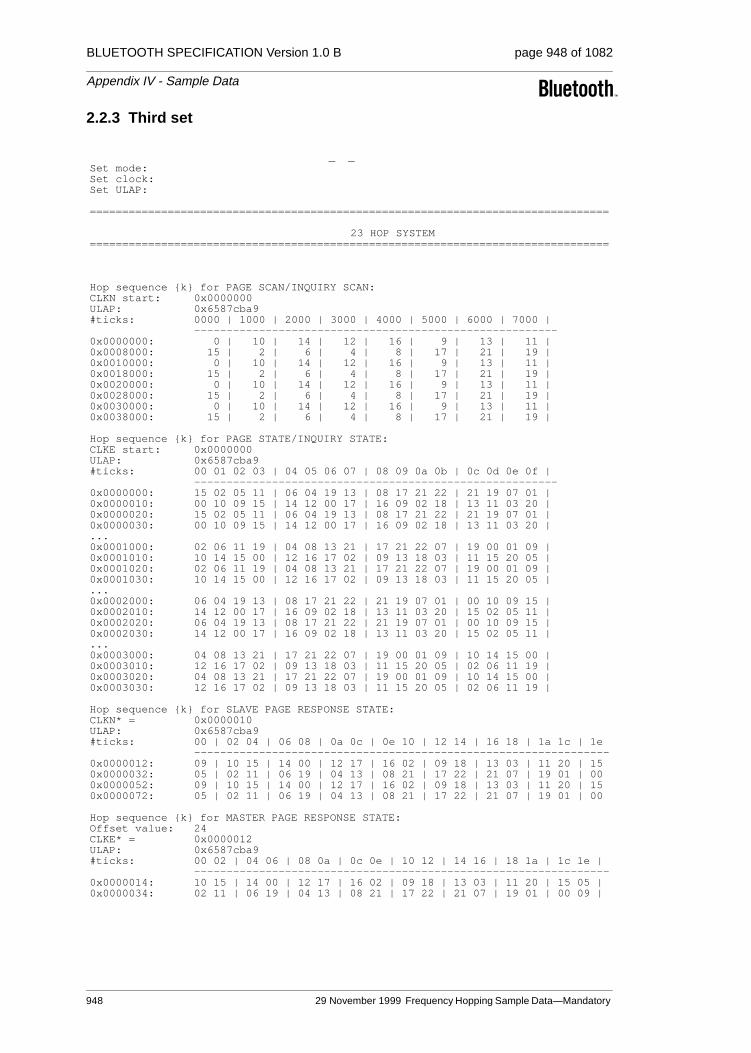
BLUETOOTH SPECIFICATION Version 1.0 B page 948 of 1082
Appendix IV - Sample Data
2.2.3 Third set
_ _Set mode: Set clock: Set ULAP:
================================================================================
23 HOP SYSTEM================================================================================
Hop sequence {k} for PAGE SCAN/INQUIRY SCAN:CLKN start: 0x0000000ULAP: 0x6587cba9#ticks: 0000 | 1000 | 2000 | 3000 | 4000 | 5000 | 6000 | 7000 |
--------------------------------------------------------0x0000000: 0 | 10 | 14 | 12 | 16 | 9 | 13 | 11 | 0x0008000: 15 | 2 | 6 | 4 | 8 | 17 | 21 | 19 | 0x0010000: 0 | 10 | 14 | 12 | 16 | 9 | 13 | 11 | 0x0018000: 15 | 2 | 6 | 4 | 8 | 17 | 21 | 19 | 0x0020000: 0 | 10 | 14 | 12 | 16 | 9 | 13 | 11 | 0x0028000: 15 | 2 | 6 | 4 | 8 | 17 | 21 | 19 | 0x0030000: 0 | 10 | 14 | 12 | 16 | 9 | 13 | 11 | 0x0038000: 15 | 2 | 6 | 4 | 8 | 17 | 21 | 19 |
Hop sequence {k} for PAGE STATE/INQUIRY STATE:CLKE start: 0x0000000ULAP: 0x6587cba9#ticks: 00 01 02 03 | 04 05 06 07 | 08 09 0a 0b | 0c 0d 0e 0f |
--------------------------------------------------------0x0000000: 15 02 05 11 | 06 04 19 13 | 08 17 21 22 | 21 19 07 01 | 0x0000010: 00 10 09 15 | 14 12 00 17 | 16 09 02 18 | 13 11 03 20 | 0x0000020: 15 02 05 11 | 06 04 19 13 | 08 17 21 22 | 21 19 07 01 | 0x0000030: 00 10 09 15 | 14 12 00 17 | 16 09 02 18 | 13 11 03 20 | ...0x0001000: 02 06 11 19 | 04 08 13 21 | 17 21 22 07 | 19 00 01 09 | 0x0001010: 10 14 15 00 | 12 16 17 02 | 09 13 18 03 | 11 15 20 05 | 0x0001020: 02 06 11 19 | 04 08 13 21 | 17 21 22 07 | 19 00 01 09 | 0x0001030: 10 14 15 00 | 12 16 17 02 | 09 13 18 03 | 11 15 20 05 | ...0x0002000: 06 04 19 13 | 08 17 21 22 | 21 19 07 01 | 00 10 09 15 | 0x0002010: 14 12 00 17 | 16 09 02 18 | 13 11 03 20 | 15 02 05 11 | 0x0002020: 06 04 19 13 | 08 17 21 22 | 21 19 07 01 | 00 10 09 15 | 0x0002030: 14 12 00 17 | 16 09 02 18 | 13 11 03 20 | 15 02 05 11 | ...0x0003000: 04 08 13 21 | 17 21 22 07 | 19 00 01 09 | 10 14 15 00 | 0x0003010: 12 16 17 02 | 09 13 18 03 | 11 15 20 05 | 02 06 11 19 | 0x0003020: 04 08 13 21 | 17 21 22 07 | 19 00 01 09 | 10 14 15 00 | 0x0003030: 12 16 17 02 | 09 13 18 03 | 11 15 20 05 | 02 06 11 19 |
Hop sequence {k} for SLAVE PAGE RESPONSE STATE:CLKN* = 0x0000010ULAP: 0x6587cba9#ticks: 00 | 02 04 | 06 08 | 0a 0c | 0e 10 | 12 14 | 16 18 | 1a 1c | 1e
----------------------------------------------------------------0x0000012: 09 | 10 15 | 14 00 | 12 17 | 16 02 | 09 18 | 13 03 | 11 20 | 15 0x0000032: 05 | 02 11 | 06 19 | 04 13 | 08 21 | 17 22 | 21 07 | 19 01 | 00 0x0000052: 09 | 10 15 | 14 00 | 12 17 | 16 02 | 09 18 | 13 03 | 11 20 | 15 0x0000072: 05 | 02 11 | 06 19 | 04 13 | 08 21 | 17 22 | 21 07 | 19 01 | 00
Hop sequence {k} for MASTER PAGE RESPONSE STATE:Offset value: 24CLKE* = 0x0000012ULAP: 0x6587cba9#ticks: 00 02 | 04 06 | 08 0a | 0c 0e | 10 12 | 14 16 | 18 1a | 1c 1e |
----------------------------------------------------------------0x0000014: 10 15 | 14 00 | 12 17 | 16 02 | 09 18 | 13 03 | 11 20 | 15 05 | 0x0000034: 02 11 | 06 19 | 04 13 | 08 21 | 17 22 | 21 07 | 19 01 | 00 09 |
948 29 November 1999 Frequency Hopping Sample Data—Mandatory

BLUETOOTH SPECIFICATION Version 1.0 B page 949 of 1082
Appendix IV - Sample Data
fh _23_C. txt0x0000054: 10 15 | 14 00 | 12 17 | 16 02 | 09 18 | 13 03 | 11 20 | 15 05 | 0x0000074: 02 11 | 06 19 | 04 13 | 08 21 | 17 22 | 21 07 | 19 01 | 00 09 |
Hop sequence {k} for CONNECTION STATE:CLK start: 0x0000010ULAP: 0x6587cba9#ticks: 00 02 | 04 06 | 08 0a | 0c 0e | 10 12 | 14 16 | 18 1a | 1c 1e |
----------------------------------------------------------------0x0000010: 16 02 | 09 18 | 13 03 | 11 20 | 15 05 | 02 11 | 06 19 | 04 13 | 0x0000030: 08 21 | 17 22 | 21 07 | 19 01 | 16 02 | 03 08 | 07 16 | 05 10 | 0x0000050: 09 18 | 02 11 | 06 19 | 04 13 | 08 21 | 18 04 | 22 12 | 20 06 | 0x0000070: 01 14 | 10 15 | 14 00 | 12 17 | 09 18 | 19 22 | 21 07 | 00 03 | 0x0000090: 02 11 | 18 04 | 20 12 | 22 08 | 01 16 | 11 20 | 13 05 | 15 01 | 0x00000b0: 17 09 | 03 06 | 05 14 | 07 10 | 02 11 | 12 15 | 14 00 | 16 19 | 0x00000d0: 18 04 | 11 20 | 13 05 | 15 01 | 17 09 | 04 13 | 06 21 | 08 17 | 0x00000f0: 10 02 | 19 22 | 21 07 | 00 03 | 03 12 | 05 02 | 09 18 | 07 04 | 0x0000110: 11 20 | 04 13 | 08 06 | 06 15 | 10 08 | 12 21 | 16 14 | 14 00 | 0x0000130: 18 16 | 20 17 | 01 10 | 22 19 | 19 05 | 21 18 | 02 11 | 00 20 | 0x0000150: 04 13 | 20 06 | 01 22 | 22 08 | 03 01 | 05 14 | 09 07 | 07 16 | 0x0000170: 11 09 | 13 10 | 17 03 | 15 12 | 12 21 | 14 09 | 16 02 | 18 13 | 0x0000190: 20 06 | 13 22 | 15 15 | 17 03 | 19 19 | 21 07 | 00 00 | 02 11 | 0x00001b0: 04 04 | 06 01 | 08 17 | 10 05 | 05 14 | 07 02 | 09 18 | 11 06 | 0x00001d0: 13 22 | 06 15 | 08 08 | 10 19 | 12 12 | 14 00 | 16 16 | 18 04 | 0x00001f0: 20 20 | 22 17 | 01 10 | 03 21 | 13 22 | 17 05 | 21 07 | 02 13 | 0x0000210: 06 15 | 22 08 | 03 10 | 07 16 | 11 18 | 15 01 | 19 03 | 00 09 | 0x0000230: 04 11 | 01 12 | 05 14 | 09 20 | 06 15 | 10 21 | 14 00 | 18 06 | 0x0000250: 22 08 | 15 01 | 19 03 | 00 09 | 04 11 | 08 17 | 12 19 | 16 02 | 0x0000270: 20 04 | 17 05 | 21 07 | 02 13 | 22 08 | 05 12 | 07 16 | 13 20 | 0x0000290: 15 01 | 08 17 | 10 21 | 16 02 | 18 06 | 01 10 | 03 14 | 09 18 | 0x00002b0: 11 22 | 12 19 | 14 00 | 20 04 | 15 01 | 21 05 | 00 09 | 06 13 | 0x00002d0: 08 17 | 01 10 | 03 14 | 09 18 | 11 22 | 17 03 | 19 07 | 02 11 | 0x00002f0: 04 15 | 05 12 | 07 16 | 13 20 | 16 02 | 04 15 | 08 17 | 20 08 | 0x0000310: 01 10 | 17 03 | 21 05 | 10 19 | 14 21 | 02 11 | 06 13 | 18 04 | 0x0000330: 22 06 | 19 07 | 00 09 | 12 00 | 09 18 | 20 08 | 01 10 | 13 01 | 0x0000350: 17 03 | 10 19 | 14 21 | 03 12 | 07 14 | 18 04 | 22 06 | 11 20 | 0x0000370: 15 22 | 12 00 | 16 02 | 05 16 | 02 11 | 15 22 | 17 03 | 08 15 | 0x0000390: 10 19 | 03 12 | 05 16 | 19 05 | 21 09 | 11 20 | 13 01 | 04 13 | 0x00003b0: 06 17 | 07 14 | 09 18 | 00 07 | 18 04 | 08 15 | 10 19 | 01 08 | 0x00003d0: 03 12 | 19 05 | 21 09 | 12 21 | 14 02 | 04 13 | 06 17 | 20 06 | 0x00003f0: 22 10 | 00 07 | 02 11 | 16 00 | 15 01 | 01 18 | 17 03 | 03 20 |
Frequency Hopping Sample Data—Mandatory Scheme29 November 1999 949
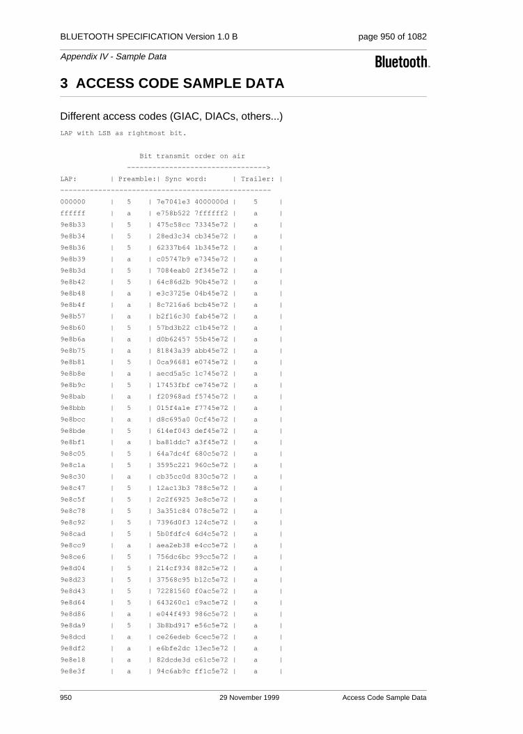
BLUETOOTH SPECIFICATION Version 1.0 B page 950 of 1082
Appendix IV - Sample Data
3 ACCESS CODE SAMPLE DATA
Different access codes (GIAC, DIACs, others...)
LAP with LSB as rightmost bit.
Bit transmit order on air
--------------------------------->
LAP: | Preamble:| Sync word: | Trailer: |
--------------------------------------------------
000000 | 5 | 7e7041e3 4000000d | 5 |
ffffff | a | e758b522 7ffffff2 | a |
9e8b33 | 5 | 475c58cc 73345e72 | a |
9e8b34 | 5 | 28ed3c34 cb345e72 | a |
9e8b36 | 5 | 62337b64 1b345e72 | a |
9e8b39 | a | c05747b9 e7345e72 | a |
9e8b3d | 5 | 7084eab0 2f345e72 | a |
9e8b42 | 5 | 64c86d2b 90b45e72 | a |
9e8b48 | a | e3c3725e 04b45e72 | a |
9e8b4f | a | 8c7216a6 bcb45e72 | a |
9e8b57 | a | b2f16c30 fab45e72 | a |
9e8b60 | 5 | 57bd3b22 c1b45e72 | a |
9e8b6a | a | d0b62457 55b45e72 | a |
9e8b75 | a | 81843a39 abb45e72 | a |
9e8b81 | 5 | 0ca96681 e0745e72 | a |
9e8b8e | a | aecd5a5c 1c745e72 | a |
9e8b9c | 5 | 17453fbf ce745e72 | a |
9e8bab | a | f20968ad f5745e72 | a |
9e8bbb | 5 | 015f4a1e f7745e72 | a |
9e8bcc | a | d8c695a0 0cf45e72 | a |
9e8bde | 5 | 614ef043 def45e72 | a |
9e8bf1 | a | ba81ddc7 a3f45e72 | a |
9e8c05 | 5 | 64a7dc4f 680c5e72 | a |
9e8c1a | 5 | 3595c221 960c5e72 | a |
9e8c30 | a | cb35cc0d 830c5e72 | a |
9e8c47 | 5 | 12ac13b3 788c5e72 | a |
9e8c5f | 5 | 2c2f6925 3e8c5e72 | a |
9e8c78 | 5 | 3a351c84 078c5e72 | a |
9e8c92 | 5 | 7396d0f3 124c5e72 | a |
9e8cad | 5 | 5b0fdfc4 6d4c5e72 | a |
9e8cc9 | a | aea2eb38 e4cc5e72 | a |
9e8ce6 | 5 | 756dc6bc 99cc5e72 | a |
9e8d04 | 5 | 214cf934 882c5e72 | a |
9e8d23 | 5 | 37568c95 b12c5e72 | a |
9e8d43 | 5 | 72281560 f0ac5e72 | a |
9e8d64 | 5 | 643260c1 c9ac5e72 | a |
9e8d86 | a | e044f493 986c5e72 | a |
9e8da9 | 5 | 3b8bd917 e56c5e72 | a |
9e8dcd | a | ce26edeb 6cec5e72 | a |
9e8df2 | a | e6bfe2dc 13ec5e72 | a |
9e8e18 | a | 82dcde3d c61c5e72 | a |
9e8e3f | a | 94c6ab9c ff1c5e72 | a |
950 29 November 1999 Access Code Sample Data

BLUETOOTH SPECIFICATION Version 1.0 B page 951 of 1082
Appendix IV - Sample Data
9e8e67 | a | 969059a6 799c5e72 | a |
9e8e90 | a | c4dfccef 425c5e72 | a |
9e8eba | 5 | 3a7fc2c3 575c5e72 | a |
9e8ee5 | 5 | 57985401 69dc5e72 | a |
9e8f11 | 5 | 0ae2a363 623c5e72 | a |
9e8f3e | a | d12d8ee7 1f3c5e72 | a |
9e8f6c | 5 | 547063a8 0dbc5e72 | a |
9e8f9b | 5 | 063ff6e1 367c5e72 | a |
9e8fcb | a | c9bc5cfe f4fc5e72 | a |
9e8ffc | 5 | 2cf00bec cffc5e72 | a |
9e902e | a | 8ec5052f 5d025e72 | a |
9e9061 | 5 | 1074b15e 61825e72 | a |
9e9095 | a | 9d59ede6 2a425e72 | a |
9e90ca | a | f0be7b24 14c25e72 | a |
9e9100 | 5 | 10e10dd0 c0225e72 | a |
9e9137 | a | f5ad5ac2 fb225e72 | a |
9e916f | a | f7fba8f8 7da25e72 | a |
9e91a8 | 5 | 2f490e5b c5625e72 | a |
9e91e2 | a | 94979982 91e25e72 | a |
9e921d | 5 | 26cda478 2e125e72 | a |
9e9259 | a | aacb81dd 26925e72 | a |
9e9296 | a | bfac7f5b da525e72 | a |
9e92d4 | a | c9a7b0a7 cad25e72 | a |
9e9313 | a | c142bdde 32325e72 | a |
616cec | 5 | 586a491f 0dcda18d | 5 |
616ceb | 5 | 37db2de7 b5cda18d | 5 |
616ce9 | 5 | 7d056ab7 65cda18d | 5 |
616ce6 | a | df61566a 99cda18d | 5 |
616ce2 | 5 | 6fb2fb63 51cda18d | 5 |
616cdd | 5 | 472bf454 2ecda18d | 5 |
616cd7 | a | c020eb21 bacda18d | 5 |
616cd0 | a | af918fd9 02cda18d | 5 |
616cc8 | a | 9112f54f 44cda18d | 5 |
616cbf | 5 | 488b2af1 bf4da18d | 5 |
616cb5 | a | cf803584 2b4da18d | 5 |
616caa | a | 9eb22bea d54da18d | 5 |
616c9e | a | a49cb509 9e4da18d | 5 |
616c91 | 5 | 06f889d4 624da18d | 5 |
616c83 | a | bf70ec37 b04da18d | 5 |
616c74 | a | ed3f797e 8b8da18d | 5 |
616c64 | 5 | 1e695bcd 898da18d | 5 |
616c53 | a | fb250cdf b28da18d | 5 |
616c41 | 5 | 42ad693c 608da18d | 5 |
616c2e | a | a5b7cc14 dd0da18d | 5 |
616c1a | a | 9f9952f7 960da18d | 5 |
616c05 | a | ceab4c99 680da18d | 5 |
616bef | a | d403ddde fdf5a18d | 5 |
616bd8 | 5 | 314f8acc c6f5a18d | 5 |
616bc0 | 5 | 0fccf05a 80f5a18d | 5 |
616ba7 | 5 | 25030d57 7975a18d | 5 |
616b8d | a | dba3037b 6c75a18d | 5 |
616b72 | 5 | 4439ce17 13b5a18d | 5 |
Access Code Sample Data 29 November 1999 951

BLUETOOTH SPECIFICATION Version 1.0 B page 952 of 1082
Appendix IV - Sample Data
616b56 | a | 8d417247 5ab5a18d | 5 |
616b39 | 5 | 6a5bd76f e735a18d | 5 |
616b1b | 5 | 592e8166 b635a18d | 5 |
616afc | 5 | 28609d46 cfd5a18d | 5 |
616adc | 5 | 51cb8c1f 4ed5a18d | 5 |
616abb | 5 | 7b047112 b755a18d | 5 |
616a99 | 5 | 4871271b e655a18d | 5 |
616a76 | 5 | 24bdc8c4 9b95a18d | 5 |
616a52 | a | edc57494 d295a18d | 5 |
616a2d | a | f989f30f 6d15a18d | 5 |
616a07 | 5 | 0729fd23 7815a18d | 5 |
6169e0 | a | 8bf0ba4f 81e5a18d | 5 |
6169b8 | a | 89a64875 0765a18d | 5 |
61698f | 5 | 6cea1f67 3c65a18d | 5 |
616965 | 5 | 2549d310 29a5a18d | 5 |
61693a | 5 | 48ae45d2 1725a18d | 5 |
61690e | 5 | 7280db31 5c25a18d | 5 |
6168e1 | a | ce1b9f34 61c5a18d | 5 |
6168b3 | 5 | 4b46727b 7345a18d | 5 |
616884 | a | ae0a2569 4845a18d | 5 |
616854 | a | ea5fc581 4a85a18d | 5 |
616823 | 5 | 33c61a3f b105a18d | 5 |
6167f1 | a | c49fb8c5 63f9a18d | 5 |
6167be | 5 | 5a2e0cb4 5f79a18d | 5 |
61678a | 5 | 60009257 1479a18d | 5 |
616755 | a | 86314e62 eab9a18d | 5 |
61671f | 5 | 3defd9bb be39a18d | 5 |
6166e8 | a | bff7e728 c5d9a18d | 5 |
6166b0 | a | bda11512 4359a18d | 5 |
616677 | 5 | 6513b3b1 fb99a18d | 5 |
61663d | a | decd2468 af19a18d | 5 |
616602 | a | f6542b5f d019a18d | 5 |
6165c6 | a | dc44b49b d8e9a18d | 5 |
616589 | 5 | 42f500ea e469a18d | 5 |
61654b | a | bf2885e1 34a9a18d | 5 |
61650c | a | ec4c69b5 4c29a18d | 5 |
952 29 November 1999 Access Code Sample Data

BLUETOOTH SPECIFICATION Version 1.0 B page 953 of 1082
Appendix IV - Sample Data
4 HEC AND PACKET HEADER SAMPLE DATA
Test vectors for HEC and header. Note that UAP, Data, and HEC are in hexa-decimal notation, while the header is in octal notation. The header is transmit-ted from left to right over air.
UAP Data HEC Header (octal not.)
--------------------------------------------
00 123 e1 770007 007070 000777
47 123 06 770007 007007 700000
00 124 32 007007 007007 007700
47 124 d5 007007 007070 707077
00 125 5a 707007 007007 077070
47 125 bd 707007 007070 777707
00 126 e2 077007 007007 000777
47 126 05 077007 007070 700000
00 127 8a 777007 007007 070007
47 127 6d 777007 007070 770770
00 11b 9e 770770 007007 777007
47 11b 79 770770 007070 077770
00 11c 4d 007770 007070 770070
47 11c aa 007770 007007 070707
00 11d 25 707770 007070 700700
47 11d c2 707770 007007 000077
00 11e 9d 077770 007070 777007
47 11e 7a 077770 007007 077770
00 11f f5 777770 007070 707777
47 11f 12 777770 007007 007000
HEC and Packet Header Sample Data 29 November 1999 953

BLUETOOTH SPECIFICATION Version 1.0 B page 954 of 1082
Appendix IV - Sample Data
5 CRC SAMPLE DATA
Sample CRC generation
Data:
-----
data[0] = 0x4e
data[1] = 0x01
data[2] = 0x02
data[3] = 0x03
data[4] = 0x04
data[5] = 0x05
data[6] = 0x06
data[7] = 0x07
data[8] = 0x08
data[9] = 0x09
UAP = 0x47
==> CRC = 6d d2
Codeword (hexadecimal notation):
---------------------------------
4e 01 02 03 04 05 06 07 08 09 6d d2
NB: Over air each byte in the codeword
is sent with the LSB first.
954 29 November 1999 CRC Sample Data

BLUETOOTH SPECIFICATION Version 1.0 B page 955 of 1082
Appendix IV - Sample Data
6 COMPLETE SAMPLE PACKETS
6.1 EXAMPLE OF DH1 PACKET
Packet header: (MSB...LSB)
--------------------------
AM_ADDR = 011
TYPE = 0100 (DH1)
FLOW = 0
ARQN = 1
SEQN = 0
Payload: (MSB...LSB)
--------------------
payload length: 5 bytes
logical channel = 10 (UA/I, Start L2CAP message)
flow = 1
data byte 1 = 00000001
data byte 2 = 00000010
data byte 3 = 00000011
data byte 4 = 00000100
data byte 5 = 00000101
HEC and CRC initialization: (MSB...LSB)
---------------------------------------
uap = 01000111
NO WHITENING USED
AIR DATA (LSB...MSB)
Packet header (incl HEC):
-------------------------
111111000
000000111000
000111000
000111111000000000000000
Payload (incl payload header and CRC):
-------------------------------------------------------------
01110100
10000000
01000000
11000000
00100000
10100000
1110110000110110
Complete Sample Packets 29 November 1999 955

BLUETOOTH SPECIFICATION Version 1.0 B page 956 of 1082
Appendix IV - Sample Data
6.2 EXAMPLE OF DM1 PACKET
Packet header: (MSB...LSB)
--------------------------
AM_ADDR = 011
TYPE = 0011 (DM1)
FLOW = 0
ARQN = 1
SEQN = 0
Payload: (MSB...LSB)
--------------------
payload length: 5 bytes
logical channel = 10 (UA/I, Start L2CAP message)
flow = 1
data byte 1 = 00000001
data byte 2 = 00000010
data byte 3 = 00000011
data byte 4 = 00000100
data byte 5 = 00000101
HEC and CRC initialization: (MSB...LSB)
---------------------------------------
uap = 01000111
NO WHITENING USED
AIR DATA (LSB...MSB)
Packet header (incl HEC):
-------------------------
111111000
111111000000
000111000
111000000111111111111000
Payload (incl payload header, FEC23, CRC and 6 padded zeros):
-------------------------------------------------------------
0111010010 11001
0000000100 01011
0000110000 11110
0000100000 00111
1010000011 01100
1011000011 00010
0110000000 10001
956 29 November 1999 Complete Sample Packets

BLUETOOTH SPECIFICATION Version 1.0 B page 957 of 1082
Appendix IV - Sample Data
7 WHITENING SEQUENCE SAMPLE DATA
Whitening sequence generator.
Whitening Whitening
Sequence LFSR
(=D7) D7.....D0
-----------------------
1 1111111
1 1101111
1 1001111
0 0001111
0 0011110
0 0111100
1 1111000
1 1100001
1 1010011
0 0110111
1 1101110
1 1001101
0 0001011
0 0010110
0 0101100
1 1011000
0 0100001
1 1000010
0 0010101
0 0101010
1 1010100
0 0111001
1 1110010
1 1110101
1 1111011
1 1100111
1 1011111
0 0101111
1 1011110
0 0101101
1 1011010
0 0100101
1 1001010
0 0000101
0 0001010
0 0010100
0 0101000
1 1010000
0 0110001
1 1100010
1 1010101
0 0111011
1 1110110
Whitening Sequence Sample Data 29 November 1999 957

BLUETOOTH SPECIFICATION Version 1.0 B page 958 of 1082
Appendix IV - Sample Data
1 1111101
1 1101011
1 1000111
0 0011111
0 0111110
1 1111100
1 1101001
1 1000011
0 0010111
0 0101110
1 1011100
0 0101001
1 1010010
0 0110101
1 1101010
1 1000101
0 0011011
0 0110110
1 1101100
1 1001001
0 0000011
0 0000110
0 0001100
0 0011000
0 0110000
1 1100000
1 1010001
0 0110011
1 1100110
1 1011101
0 0101011
1 1010110
0 0111101
1 1111010
1 1100101
1 1011011
0 0100111
1 1001110
0 0001101
0 0011010
0 0110100
1 1101000
1 1000001
0 0010011
0 0100110
1 1001100
0 0001001
0 0010010
0 0100100
1 1001000
0 0000001
0 0000010
958 29 November 1999 Whitening Sequence Sample Data

BLUETOOTH SPECIFICATION Version 1.0 B page 959 of 1082
Appendix IV - Sample Data
0 0000100
0 0001000
0 0010000
0 0100000
1 1000000
0 0010001
0 0100010
1 1000100
0 0011001
0 0110010
1 1100100
1 1011001
0 0100011
1 1000110
0 0011101
0 0111010
1 1110100
1 1111001
1 1100011
1 1010111
0 0111111
1 1111110
1 1101101
1 1001011
0 0000111
0 0001110
0 0011100
0 0111000
1 1110000
1 1110001
1 1110011
1 1110111
1 1111111
Whitening Sequence Sample Data 29 November 1999 959

BLUETOOTH SPECIFICATION Version 1.0 B page 960 of 1082
Appendix IV - Sample Data
8 FEC SAMPLE DATA
================================================
Rate 2/3 FEC -- (15,10) Shortened Hamming Code
================================================
Data is in hexadecimal notation, the codewords are in binary notation. The codeword bits are sent from left to right over the air interface. The space in the codeword indicates the start of parity bits.
Data: Codeword:
0x001 1000000000 11010
0x002 0100000000 01101
0x004 0010000000 11100
0x008 0001000000 01110
0x010 0000100000 00111
0x020 0000010000 11001
0x040 0000001000 10110
0x080 0000000100 01011
0x100 0000000010 11111
0x200 0000000001 10101
960 29 November 1999 FEC Sample Data

BLUETOOTH SPECIFICATION Version 1.0 B page 961 of 1082
Appendix IV - Sample Data
9 ENCRYPTION KEY SAMPLE DATA
Explanation:
Key [ i]: denotes the ith sub-key in Ar or A’r;round r: denotes the input to the rth round;added ->: denotes the input to round 3 in
A’r after adding original input (of round 1).
9.1 FOUR TESTS OF E1
rand :00000000000000000000000000000000
address :000000000000
key :00000000000000000000000000000000
round 1:00000000000000000000000000000000
Key [ 1]:00000000000000000000000000000000
Key [ 2]:4697b1baa3b7100ac537b3c95a28ac64
round 2:78d19f9307d2476a523ec7a8a026042a
Key [ 3]:ecabaac66795580df89af66e66dc053d
Key [ 4]:8ac3d8896ae9364943bfebd4969b68a0
round 3:600265247668dda0e81c07bbb30ed503
Key [ 5]:5d57921fd5715cbb22c1be7bbc996394
Key [ 6]:2a61b8343219fdfb1740e6511d41448f
round 4:d7552ef7cc9dbde568d80c2215bc4277
Key [ 7]:dd0480dee731d67f01a2f739da6f23ca
Key [ 8]:3ad01cd1303e12a1cd0fe0a8af82592c
round 5:fb06bef32b52ab8f2a4f2b6ef7f6d0cd
Key [ 9]:7dadb2efc287ce75061302904f2e7233
Key [10]:c08dcfa981e2c4272f6c7a9f52e11538
round 6:b46b711ebb3cf69e847a75f0ab884bdd
Key [11]:fc2042c708e409555e8c147660ffdfd7
Key [12]:fa0b21001af9a6b9e89e624cd99150d2
round 7:c585f308ff19404294f06b292e978994
Key [13]:18b40784ea5ba4c80ecb48694b4e9c35
Key [14]:454d54e5253c0c4a8b3fcca7db6baef4
round 8:2665fadb13acf952bf74b4ab12264b9f
Key [15]:2df37c6d9db52674f29353b0f011ed83
Key [16]:b60316733b1e8e70bd861b477e2456f1
Key [17]:884697b1baa3b7100ac537b3c95a28ac
round 1:158ffe43352085e8a5ec7a88e1ff2ba8
Key [ 1]:e9e5dfc1b3a79583e9e5dfc1b3a79583
Key [ 2]:7595bf57e0632c59f435c16697d4c864
round 2:0b5cc75febcdf7827ca29ec0901b6b5b
Key [ 3]:e31b96afcc75d286ef0ae257cbbc05b7
Key [ 4]:0d2a27b471bc0108c6263aff9d9b3b6b
round 3:e4278526c8429211f7f2f0016220aef4
added ->:f1b68365fd6217f952de6a89831fd95c
Key [ 5]:98d1eb5773cf59d75d3b17b3bc37c191
Key [ 6]:fd2b79282408ddd4ea0aa7511133336f
round 4:d0304ad18337f86040145d27aa5c8153
Key [ 7]:331227756638a41d57b0f7e071ee2a98
Encryption Key Sample Data 29 November 1999 961

BLUETOOTH SPECIFICATION Version 1.0 B page 962 of 1082
Appendix IV - Sample Data
Key [ 8]:aa0dd8cc68b406533d0f1d64aabacf20
round 5:84db909d213bb0172b8b6aaf71bf1472
Key [ 9]:669291b0752e63f806fce76f10e119c8
Key [10]:ef8bdd46be8ee0277e9b78adef1ec154
round 6:f835f52921e903dfa762f1df5abd7f95
Key [11]:f3902eb06dc409cfd78384624964bf51
Key [12]:7d72702b21f97984a721c99b0498239d
round 7:ae6c0b4bb09f25c6a5d9788a31b605d1
Key [13]:532e60bceaf902c52a06c2c283ecfa32
Key [14]:181715e5192efb2a64129668cf5d9dd4
round 8:744a6235b86cc0b853cc9f74f6b65311
Key [15]:83017c1434342d4290e961578790f451
Key [16]:2603532f365604646ff65803795ccce5
Key [17]:882f7c907b565ea58dae1c928a0dcf41
sres :056c0fe6
aco :48afcdd4bd40fef76693b113
-----------------------------------------
rand :bc3f30689647c8d7c5a03ca80a91eceb
address :7ca89b233c2d
key :159dd9f43fc3d328efba0cd8a861fa57
round 1:bc3f30689647c8d7c5a03ca80a91eceb
Key [ 1]:159dd9f43fc3d328efba0cd8a861fa57
Key [ 2]:326558b3c15551899a97790e65ff669e
round 2:3e950edf197615638cc19c09f8fedc9b
Key [ 3]:62e879b65b9f53bbfbd020c624b1d682
Key [ 4]:73415f30bac8ab61f410adc9442992db
round 3:6a7640791cb536678936c5ecd4ae5a73
Key [ 5]:5093cfa1d31c1c48acd76df030ea3c31
Key [ 6]:0b4acc2b8f1f694fc7bd91f4a70f3009
round 4:fca2c022a577e2ffb2aa007589693ec7
Key [ 7]:2ca43fc817947804ecff148d50d6f6c6
Key [ 8]:3fcd73524b533e00b7f7825bea2040a4
round 5:e97f8ea4ed1a6f4a36ffc179dc6bb563
Key [ 9]:6c67bec76ae8c8cc4d289f69436d3506
Key [10]:95ed95ee8cb97e61d75848464bffb379
round 6:38b07261d7340d028749de1773a415c7
Key [11]:ff566c1fc6b9da9ac502514550f3e9d2
Key [12]:ab5ce3f5c887d0f49b87e0d380e12f47
round 7:58241f1aed7c1c3e047d724331a0b774
Key [13]:a2cab6f95eac7d655dbe84a6cd4c47f5
Key [14]:f5caff88af0af8c42a20b5bbd2c8b460
round 8:3d1aaeff53c0910de63b9788b13c490f
Key [15]:185099c1131cf97001e2f36fda415025
Key [16]:a0ebb82676bc75e8378b189eff3f6b1d
Key [17]:cf5b348aaee27ae332b4f1bfa10289a6
round 1:2e4b417b9a2a9cfd7d8417d9a6a556eb
Key [ 1]:fe78b835f26468ab069fd3991b086fda
Key [ 2]:095c5a51c6fa6d3ac1d57fa19aa382bd
round 2:b8bca81d6bb45af9d92beadd9300f5ed
Key [ 3]:1af866df817fd9f4ec00bc704192cffc
Key [ 4]:f4a8a059c1f575f076f5fbb24bf16590
round 3:351aa16dec2c3a4787080249ed323eae
962 29 November 1999 Encryption Key Sample Data

BLUETOOTH SPECIFICATION Version 1.0 B page 963 of 1082
Appendix IV - Sample Data
added ->:1b65e2167656d6bafa8c19904bd79445
Key [ 5]:8c9d18d9356a9954d341b4286e88ea1f
Key [ 6]:5c958d370102c9881bf753e69c7da029
round 4:2ce8fef47dda6a5bee74372e33e478a2
Key [ 7]:7eb2985c3697429fbe0da334bb51f795
Key [ 8]:af900f4b63a1138e2874bfb7c628b7b8
round 5:572787f563e1643c1c862b7555637fb4
Key [ 9]:834c8588dd8f3d4f31117a488420d69b
Key [10]:bc2b9b81c15d9a80262f3f48e9045895
round 6:16b4968c5d02853c3a43aa4cdb5f26ac
Key [11]:f08608c9e39ad3147cba61327919c958
Key [12]:2d4131decf4fa3a959084714a9e85c11
round 7:10e4120c7cccef9dd4ba4e6da8571b01
Key [13]:c934fd319c4a2b5361fa8eef05ae9572
Key [14]:4904c17aa47868e40471007cde3a97c0
round 8:f9081772498fed41b6ffd72b71fcf6c6
Key [15]:ea5e28687e97fa3f833401c86e6053ef
Key [16]:1168f58252c4ecfccafbdb3af857b9f2
Key [17]:b3440f69ef951b78b5cbd6866275301b
sres :8d5205c5
aco :3ed75df4abd9af638d144e94
-----------------------------------------
rand :0891caee063f5da1809577ff94ccdcfb
address :c62f19f6ce98
key :45298d06e46bac21421ddfbed94c032b
round 1:0891caee063f5da1809577ff94ccdcfb
Key [ 1]:45298d06e46bac21421ddfbed94c032b
Key [ 2]:8f03e1e1fe1c191cad35a897bc400597
round 2:1c6ca013480a685c1b28e0317f7167e1
Key [ 3]:4f2ce3a092dde854ef496c8126a69e8e
Key [ 4]:968caee2ac6d7008c07283daec67f2f2
round 3:06b4915f5fcc1fc551a52048f0af8a26
Key [ 5]:ab0d5c31f94259a6bf85ee2d22edf56c
Key [ 6]:dfb74855c0085ce73dc17b84bfd50a92
round 4:077a92b040acc86e6e0a877db197a167
Key [ 7]:8f888952662b3db00d4e904e7ea53b5d
Key [ 8]:5e18bfcc07799b0132db88cd6042f599
round 5:7204881fb300914825fdc863e8ceadf3
Key [ 9]:bfca91ad9bd3d1a06c582b1d5512dddf
Key [10]:a88bc477e3fa1d5a59b5e6cf793c7a41
round 6:27031131d86cea2d747deb4f756143aa
Key [11]:f3cfb8dac8aea2a6a8ef95af3a2a2767
Key [12]:77beb90670c5300b03aa2b2232d3d40c
round 7:fc8c13d49149b1ce8d86f96e44a00065
Key [13]:b578373650af36a06e19fe335d726d32
Key [14]:6bcee918c7d0d24dfdf42237fcf99d53
round 8:04ef5f5a7ddf846cda0a07782fc23866
Key [15]:399f158241eb3e079f45d7b96490e7ea
Key [16]:1bcfbe98ecde2add52aa63ea79fb917a
Key [17]:ee8bc03ec08722bc2b075492873374af
round 1:d989d7a40cde7032d17b52f8117b69d5
Key [ 1]:2ecc6cc797cc41a2ab02007f6af396ae
Encryption Key Sample Data 29 November 1999 963

BLUETOOTH SPECIFICATION Version 1.0 B page 964 of 1082
Appendix IV - Sample Data
Key [ 2]:acfaef7609c12567d537ae1cf9dc2198
round 2:8e76eb9a29b2ad5eea790db97aee37c1
Key [ 3]:079c8ff9b73d428df879906a0b87a6c8
Key [ 4]:19f2710baf403a494193d201f3a8c439
round 3:346bb7c35b2539676375aafe3af69089
added ->:edf48e675703a955b2f0fc062b71f95c
Key [ 5]:d623a6498f915cb2c8002765247b2f5a
Key [ 6]:900109093319bc30108b3d9434a77a72
round 4:fafb6c1f3ebbd2477be2da49dd923f69
Key [ 7]:e28e2ee6e72e7f4e5b5c11f10d204228
Key [ 8]:8e455cd11f8b9073a2dfa5413c7a4bc5
round 5:7c72230df588060a3cf920f9b0a08f06
Key [ 9]:28afb26e2c7a64238c41cefc16c53e74
Key [10]:d08dcafc2096395ba0d2dddd0e471f4d
round 6:55991df991db26ff00073a12baa3031d
Key [11]:fcffdcc3ad8faae091a7055b934f87c1
Key [12]:f8df082d77060252c02d91e55bd6a7d6
round 7:70ec682ff864375f63701fa4f6be5377
Key [13]:bef3706e523d708e8a44147d7508bc35
Key [14]:3e98ab283ca2422d56a56cf8b06caeb3
round 8:172f12ec933da85504b4ea5c90f8f0ea
Key [15]:87ad9625d06645d22598dd5ef811ea2c
Key [16]:8bd3db0cc8168009e5da90877e13a36f
Key [17]:0e74631d813a8351ac7039b348c41b42
sres :00507e5f
aco :2a5f19fbf60907e69f39ca9f
-----------------------------------------
rand :0ecd61782b4128480c05dc45542b1b8c
address :f428f0e624b3
key :35949a914225fabad91995d226de1d92
round 1:0ecd61782b4128480c05dc45542b1b8c
Key [ 1]:35949a914225fabad91995d226de1d92
Key [ 2]:ea6b3dcccc8ee5d88de349fa5010404f
round 2:8935e2e263fbc4b9302cabdfc06bce3e
Key [ 3]:920f3a0f2543ce535d4e7f25ad80648a
Key [ 4]:ad47227edf9c6874e80ba80ebb95d2c9
round 3:b4c8b878675f184a0c72f3dab51f8f05
Key [ 5]:81a941ca7202b5e884ae8fa493ecac3d
Key [ 6]:bcde1520bee3660e86ce2f0fb78b9157
round 4:77ced9f2fc42bdd5c6312b87fc2377c5
Key [ 7]:c8eee7423d7c6efa75ecec0d2cd969d3
Key [ 8]:910b3f838a02ed441fbe863a02b4a1d0
round 5:fe28e8056f3004d60bb207e628b39cf2
Key [ 9]:56c647c1e865eb078348962ae070972d
Key [10]:883965da77ca5812d8104e2b640aec0d
round 6:1f2ba92259d9e88101518f145a33840f
Key [11]:61d4cb7e4f8868a283327806a9bd8d4d
Key [12]:9f57de3a3ff310e21dc1e696ce060304
round 7:cc9b5d0218d29037e88475152ebebb2f
Key [13]:7aa1d8adc1aeed7127ef9a18f6eb2d8e
Key [14]:b4db9da3bf865912acd14904c7f7785d
round 8:b04d352bedc02682e4a7f59d7cda1dba
964 29 November 1999 Encryption Key Sample Data

BLUETOOTH SPECIFICATION Version 1.0 B page 965 of 1082
Appendix IV - Sample Data
Key [15]:a13d7141ef1f6c7d867e3d175467381b
Key [16]:08b2bc058e50d6141cdd566a307e1acc
Key [17]:057b2b4b4be5dc0ac49e50489b8006c9
round 1:5cfacc773bae995cd7f1b81e7c9ec7df
Key [ 1]:1e717950f5828f3930fe4a9395858815
Key [ 2]:d1623369b733d98bbc894f75866c544c
round 2:d571ffa21d9daa797b1a0a3c962fc64c
Key [ 3]:4abf27664ae364cc8a7e5bcf88214cc4
Key [ 4]:2aaedda8dc4933dd6aeaf6e5c0d5a482
round 3:e17c8e498a00f125bf654c938c23f36d
added ->:bd765a3eb1ae8a796856048df0c1bab2
Key [ 5]:bc7f8ab2d86000f47b1946cc8d7a7a2b
Key [ 6]:6b28544cb13ec6c5d98470df2cf900b7
round 4:a9727c26f2f06bd9920e83c8605dcd76
Key [ 7]:1be840d9107f2c9523f66bb19f5464a1
Key [ 8]:61d6fb1aa2f0c2b26fb2a3d6de8c177c
round 5:aeff751f146eab7e4626b2e2c9e2fb39
Key [ 9]:adabfc82570c568a233173099f23f4c2
Key [10]:b7df6b55ad266c0f1ff7452101f59101
round 6:cf412b95f454d5185e67ca671892e5bd
Key [11]:8e04a7282a2950dcbaea28f300e22de3
Key [12]:21362c114433e29bda3e4d51f803b0cf
round 7:16165722fe4e07ef88f8056b17d89567
Key [13]:710c8fd5bb3cbb5f132a7061de518bd9
Key [14]:0791de7334f4c87285809343f3ead3bd
round 8:28854cd6ad4a3c572b15490d4b81bc3f
Key [15]:4f47f0e5629a674bfcd13770eb3a3bd9
Key [16]:58a6d9a16a284cc0aead2126c79608a1
Key [17]:a564082a0a98399f43f535fd5cefad34
sres :80e5629c
aco :a6fe4dcde3924611d3cc6ba1
=========================================
9.2 FOUR TESTS OF E21
rand :00000000000000000000000000000000
address :000000000000
round 1:00000000000000000000000000000000
Key [ 1]:00000000000000000000000000000006
Key [ 2]:4697b1baa3b7100ac537b3c95a28dc94
round 2:98611307ab76bbde9a86af1ce8cad412
Key [ 3]:ecabaac66795580df89af66e665d863d
Key [ 4]:8ac3d8896ae9364943bfebd4a2a768a0
round 3:820999ad2e6618f4b578974beeedf9e7
added ->:820999ad2e6618f4b578974beeedf9e7
Key [ 5]:5d57921fd5715cbb22c1bedb1c996394
Key [ 6]:2a61b8343219fdfb1740e9541d41448f
round 4:acd6edec87581ac22dbdc64ea4ced3a2
Key [ 7]:dd0480dee731d67f01ba0f39da6f23ca
Key [ 8]:3ad01cd1303e12a18dcfe0a8af82592c
Encryption Key Sample Data 29 November 1999 965

BLUETOOTH SPECIFICATION Version 1.0 B page 966 of 1082
Appendix IV - Sample Data
round 5:1c7798732f09fbfe25795a4a2fbc93c2
Key [ 9]:7dadb2efc287ce7b0c1302904f2e7233
Key [10]:c08dcfa981e2f4572f6c7a9f52e11538
round 6:c05b88b56aa70e9c40c79bb81cd911bd
Key [11]:fc2042c708658a555e8c147660ffdfd7
Key [12]:fa0b21002605a6b9e89e624cd99150d2
round 7:abacc71b481c84c798d1bdf3d62f7e20
Key [13]:18b407e44a5ba4c80ecb48694b4e9c35
Key [14]:454d57e8253c0c4a8b3fcca7db6baef4
round 8:e8204e1183ae85cf19edb2c86215b700
Key [15]:2d0b946d9db52674f29353b0f011ed83
Key [16]:76c316733b1e8e70bd861b477e2456f1
Key [17]:8e4697b1baa3b7100ac537b3c95a28ac
Ka :d14ca028545ec262cee700e39b5c39ee
-----------------------------------------
rand :2dd9a550343191304013b2d7e1189d09
address :cac4364303b6
round 1:cac4364303b6cac4364303b6cac43643
Key [ 1]:2dd9a550343191304013b2d7e1189d0f
Key [ 2]:14c4335b2c43910c5dcc71d81a14242b
round 2:e169f788aad45a9011f11db5270b1277
Key [ 3]:55bfb712cba168d1a48f6e74cd9f4388
Key [ 4]:2a2b3aacca695caef2821b0fb48cc253
round 3:540f9c76652e92c44987c617035037bf
added ->:9ed3d23566e45c007fcac9a1c9146dfc
Key [ 5]:a06aab22d9a287384042976b4b6b00ee
Key [ 6]:c229d054bb72e8eb230e6dcdb32d16b7
round 4:83659a41675f7171ea57909dc5a79ab4
Key [ 7]:23c4812ab1905ddf77dedaed4105649a
Key [ 8]:40d87e272a7a1554ae2e85e3638cdf52
round 5:0b9382d0ed4f2fccdbb69d0db7b130a4
Key [ 9]:bdc064c6a39f6b84fe40db359f62a3c4
Key [10]:58228db841ce3cee983aa721f36aa1b9
round 6:c6ebda0f8f489792f09c189568226c1f
Key [11]:a815bacd6fa747a0d4f52883ac63ebe7
Key [12]:a9ce513b38ea006c333ecaaefcf1d0f8
round 7:75a8aba07e69c9065bcd831c40115116
Key [13]:3635e074792d4122130e5b824e52cd60
Key [14]:511bdb61bb28de72a5d794bffbf407df
round 8:57a6e279dcb764cf7dd6a749dd60c735
Key [15]:a32f5f21044b6744b6d913b13cdb4c0a
Key [16]:9722bbaeef281496ef8c23a9d41e92f4
Key [17]:807370560ad7e8a13a054a65a03b4049
Ka :e62f8bac609139b3999aedbc9d228042
-----------------------------------------
rand :dab3cffe9d5739d1b7bf4a667ae5ee24
address :02f8fd4cd661
round 1:02f8fd4cd66102f8fd4cd66102f8fd4c
Key [ 1]:dab3cffe9d5739d1b7bf4a667ae5ee22
Key [ 2]:e315a8a65d809ec7c289e69c899fbdcc
round 2:ef85ff081b8709405e19f3e275cec7dc
Key [ 3]:df6a119bb50945fc8a3394e7216448f3
966 29 November 1999 Encryption Key Sample Data

BLUETOOTH SPECIFICATION Version 1.0 B page 967 of 1082
Appendix IV - Sample Data
Key [ 4]:87fe86fb0d58b5dd0fb3b6b1dab51d07
round 3:aa25c21bf577d92dd97381e3e9edcc54
added ->:a81dbf5723d8dbd524bf5782ebe5c918
Key [ 5]:36cc253c506c0021c91fac9d8c469e90
Key [ 6]:d5fda00f113e303809b7f7d78a1a2b0e
round 4:9e69ce9b53caec3990894d2baed41e0d
Key [ 7]:c14b5edc10cabf16bc2a2ba4a8ae1e40
Key [ 8]:74c6131afc8dce7e11b03b1ea8610c16
round 5:a5460fa8cedca48a14fd02209e01f02e
Key [ 9]:346cfc553c6cbc9713edb55f4dcbc96c
Key [10]:bddf027cb059d58f0509f8963e9bdec6
round 6:92b33f11eadcacc5a43dd05f13d334dd
Key [11]:8eb9e040c36c4c0b4a7fd3dd354d53c4
Key [12]:c6ffecdd5e135b20879b9dfa4b34bf51
round 7:fb0541aa5e5df1a61c51aef606eb5a41
Key [13]:bf12f5a6ba08dfc4fda4bdfc68c997d9
Key [14]:37c4656b9215f3c959ea688fb64ad327
round 8:f0bbd2b94ae374346730581fc77a9c98
Key [15]:e87bb0d86bf421ea4f779a8eee3a866c
Key [16]:faa471e934fd415ae4c0113ec7f0a5ad
Key [17]:95204a80b8400e49db7cf6fd2fd40d9a
Ka :b0376d0a9b338c2e133c32b69cb816b3
-----------------------------------------
rand :13ecad08ad63c37f8a54dc56e82f4dc1
address :9846c5ead4d9
round 1:9846c5ead4d99846c5ead4d99846c5ea
Key [ 1]:13ecad08ad63c37f8a54dc56e82f4dc7
Key [ 2]:ad04f127bed50b5e671d6510d392eaed
round 2:97374e18cdd0a6f7a5aa49d1ac875c84
Key [ 3]:57ad159e5774fa222f2f3039b9cd5101
Key [ 4]:9a1e9e1068fede02ef90496e25fd8e79
round 3:9dd3260373edd9d5f4e774826b88fd2d
added ->:0519ebe9a7c6719331d1485bf3cec2c7
Key [ 5]:378dce167db62920b0b392f7cfca316e
Key [ 6]:db4277795c87286faee6c9e9a6b71a93
round 4:40ec6563450299ac4e120d88672504d6
Key [ 7]:ec01aa2f5a8a793b36c1bb858d254380
Key [ 8]:2921a66cfa5bf74ac535424564830e98
round 5:57287bbb041bd6a56c2bd931ed410cd4
Key [ 9]:07018e45aab61b3c3726ee3d57dbd5f6
Key [10]:627381f0fa4c02b0c7d3e7dfbffc3333
round 6:66affa66a8dcd36e36bf6c3f1c6a276e
Key [11]:33b57c925bd5551999f716e138efbe79
Key [12]:a6dc7f9aa95bcc9243aebd12608f657a
round 7:450e65184fd8c72c578d5cdecb286743
Key [13]:a6a6db00fd8c72a28ea57ea542f6e102
Key [14]:dcf3377daeb2e24e61f0ad6620951c1f
round 8:e5eb180b519a4e673f21b7c4f4573f3d
Key [15]:621240b9506b462a7fa250da41844626
Key [16]:ae297810f01f43dc35756cd119ee73d6
Key [17]:b959835ec2501ad3894f8b8f1f4257f9
Ka :5b61e83ad04d23e9d1c698851fa30447
Encryption Key Sample Data 29 November 1999 967
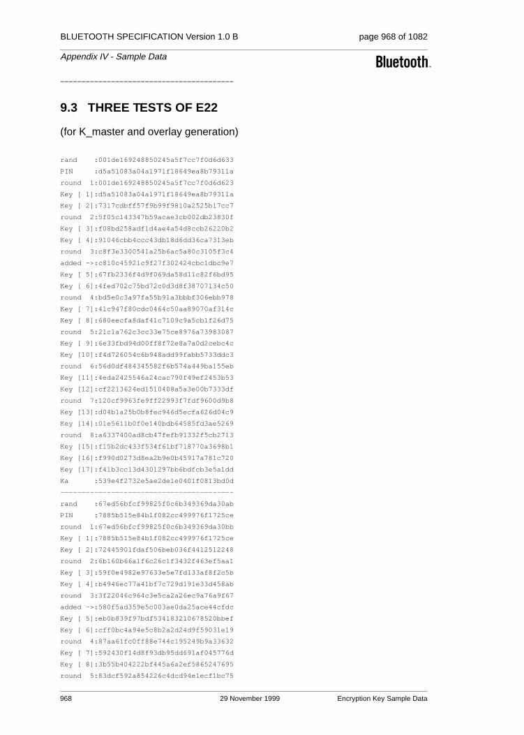
BLUETOOTH SPECIFICATION Version 1.0 B page 968 of 1082
Appendix IV - Sample Data
=========================================
9.3 THREE TESTS OF E22
(for K_master and overlay generation)
rand :001de169248850245a5f7cc7f0d6d633
PIN :d5a51083a04a1971f18649ea8b79311a
round 1:001de169248850245a5f7cc7f0d6d623
Key [ 1]:d5a51083a04a1971f18649ea8b79311a
Key [ 2]:7317cdbff57f9b99f9810a2525b17cc7
round 2:5f05c143347b59acae3cb002db23830f
Key [ 3]:f08bd258adf1d4ae4a54d8ccb26220b2
Key [ 4]:91046cbb4ccc43db18d6dd36ca7313eb
round 3:c8f3e3300541a25b6ac5a80c3105f3c4
added ->:c810c45921c9f27f302424cbc1dbc9e7
Key [ 5]:67fb2336f4d9f069da58d11c82f6bd95
Key [ 6]:4fed702c75bd72c0d3d8f38707134c50
round 4:bd5e0c3a97fa55b91a3bbbf306ebb978
Key [ 7]:41c947f80cdc0464c50aa89070af314c
Key [ 8]:680eecfa8daf41c7109c9a5cb1f26d75
round 5:21c1a762c3cc33e75ce8976a73983087
Key [ 9]:6e33fbd94d00ff8f72e8a7a0d2cebc4c
Key [10]:f4d726054c6b948add99fabb5733ddc3
round 6:56d0df484345582f6b574a449ba155eb
Key [11]:4eda2425546a24cac790f49ef2453b53
Key [12]:cf2213624ed1510408a5a3e00b7333df
round 7:120cf9963fe9ff22993f7fdf9600d9b8
Key [13]:d04b1a25b0b8fec946d5ecfa626d04c9
Key [14]:01e5611b0f0e140bdb64585fd3ae5269
round 8:a6337400ad8cb47fefb91332f5cb2713
Key [15]:f15b2dc433f534f61bf718770a3698b1
Key [16]:f990d0273d8ea2b9e0b45917a781c720
Key [17]:f41b3cc13d4301297bb6bdfcb3e5a1dd
Ka :539e4f2732e5ae2de1e0401f0813bd0d
-----------------------------------------
rand :67ed56bfcf99825f0c6b349369da30ab
PIN :7885b515e84b1f082cc499976f1725ce
round 1:67ed56bfcf99825f0c6b349369da30bb
Key [ 1]:7885b515e84b1f082cc499976f1725ce
Key [ 2]:72445901fdaf506beb036f4412512248
round 2:6b160b66a1f6c26c1f3432f463ef5aa1
Key [ 3]:59f0e4982e97633e5e7fd133af8f2c5b
Key [ 4]:b4946ec77a41bf7c729d191e33d458ab
round 3:3f22046c964c3e5ca2a26ec9a76a9f67
added ->:580f5ad359e5c003ae0da25ace44cfdc
Key [ 5]:eb0b839f97bdf534183210678520bbef
Key [ 6]:cff0bc4a94e5c8b2a2d24d9f59031e19
round 4:87aa61fc0ff88e744c195249b9a33632
Key [ 7]:592430f14d8f93db95dd691af045776d
Key [ 8]:3b55b404222bf445a6a2ef5865247695
round 5:83dcf592a854226c4dcd94e1ecf1bc75
968 29 November 1999 Encryption Key Sample Data

BLUETOOTH SPECIFICATION Version 1.0 B page 969 of 1082
Appendix IV - Sample Data
Key [ 9]:a9714b86319ef343a28b87456416bd52
Key [10]:e6598b24390b3a0bf2982747993b0d78
round 6:dee0d13a52e96bcf7c72045a21609fc6
Key [11]:62051d8c51973073bff959b032c6e1e2
Key [12]:29e94f4ab73296c453c833e217a1a85b
round 7:08488005761e6c7c4dbb203ae453fe3a
Key [13]:0e255970b3e2fc235f59fc5acb10e8ce
Key [14]:d0dfbb3361fee6d4ffe45babf1cd7abf
round 8:0d81e89bddde7a7065316c47574feb8f
Key [15]:c12eee4eb38b7a171f0f736003774b40
Key [16]:8f962523f1c0abd9a087a0dfb11643d3
Key [17]:24be1c66cf8b022f12f1fb4c60c93fd1
Ka :04435771e03a9daceb8bb1a493ee9bd8
-----------------------------------------
rand :40a94509238664f244ff8e3d13b119d3
PIN :1ce44839badde30396d03c4c36f23006
round 1:40a94509238664f244ff8e3d13b119c3
Key [ 1]:1ce44839badde30396d03c4c36f23006
Key [ 2]:6dd97a8f91d628be4b18157af1a9dcba
round 2:0eac5288057d9947a24eabc1744c4582
Key [ 3]:fef9583d5f55fd4107ad832a725db744
Key [ 4]:fc3893507016d7c1db2bd034a230a069
round 3:60b424f1082b0cc3bd61be7b4c0155f0
added ->:205d69f82bb17031f9604c465fb26e33
Key [ 5]:0834d04f3e7e1f7f85f0c1db685ab118
Key [ 6]:1852397f9a3723169058e9b62bb3682b
round 4:2c6b65a49d66af6566675afdd6fa7d7d
Key [ 7]:6c10da21d762ae4ac1ba22a96d9007b4
Key [ 8]:9aa23658b90470a78d686344b8a9b0e7
round 5:a2c537899665113a42f1ac24773bdc31
Key [ 9]:137dee3bf879fe7bd02fe6d888e84f16
Key [10]:466e315a1863f47d0f93bc6827cf3450
round 6:e26982980d79b21ed3e20f8c3e71ba96
Key [11]:0b33cf831465bb5c979e6224d7f79f7c
Key [12]:92770660268ede827810d707a0977d73
round 7:e7b063c4e2e3110b89b7e1631c762dd5
Key [13]:7be30ae4961cf24ca17625a77bb7a9f8
Key [14]:be65574a33ae30e6e82dbd2826d3cc1a
round 8:7a963e37b2c2e76b489cfe40a2cf00e5
Key [15]:ed0ba7dd30d60a5e69225f0a33011e5b
Key [16]:765c990f4445e52b39e6ed6105ad1c4f
Key [17]:52627bf9f35d94f30d5b07ef15901adc
Ka :9cde4b60f9b5861ed9df80858bac6f7f
=========================================
Encryption Key Sample Data 29 November 1999 969

BLUETOOTH SPECIFICATION Version 1.0 B page 970 of 1082
Appendix IV - Sample Data
9.4 TESTS OF E22 WITH PIN AUGMENTING
for PIN lengths 1,...,16 bytes
rand :24b101fd56117d42c0545a4247357048
PIN length =16 octets
PIN :fd397c7f5c1f937cdf82d8816cc377e2
round 1:24b101fd56117d42c0545a4247357058
Key [ 1]:fd397c7f5c1f937cdf82d8816cc377e2
Key [ 2]:0f7aac9c9b53f308d9fdbf2c78e3c30e
round 2:838edfe1226266953ccba8379d873107
Key [ 3]:0b8ac18d4bb44fad2efa115e43945abc
Key [ 4]:887b16b062a83bfa469772c25b456312
round 3:8cd0c9283120aba89a7f9d635dd4fe3f
added ->:a881cad5673128ea5ad3f7211a096e67
Key [ 5]:2248cbe6d299e9d3e8fd35a91178f65b
Key [ 6]:b92af6237385bd31f8fb57fb1bdd824e
round 4:2648d9c618a622b10ef80c4dbaf68b99
Key [ 7]:2bf5ffe84a37878ede2d4c30be60203b
Key [ 8]:c9cb6cec60cb8a8f29b99fcf3e71e40f
round 5:b5a7d9e96f68b14ccebf361de3914d0f
Key [ 9]:5c2f8a702e4a45575b103b0cce8a91c6
Key [10]:d453db0c9f9ddbd11e355d9a34d9b11b
round 6:632a091e7eefe1336857ddafd1ff3265
Key [11]:32805db7e59c5ed4acabf38d27e3fece
Key [12]:fde3a8eedfa3a12be09c1a8a00890fd7
round 7:048531e9fd3efa95910540150f8b137b
Key [13]:def07eb23f3a378f059039a2124bc4c2
Key [14]:2608c58f23d84a09b9ce95e5caac1ab4
round 8:461814ec7439d412d0732f0a6f799a6a
Key [15]:0a7ed16481a623e56ee1442ffa74f334
Key [16]:12add59aca0d19532f1516979954e369
Key [17]:dd43d02d39ffd6a386a4b98b4ac6eb23
Ka :a5f2adf328e4e6a2b42f19c8b74ba884
-----------------------------------------
rand :321964061ac49a436f9fb9824ac63f8b
PIN length =15 octets
PIN :ad955d58b6b8857820ac1262d617a6
address :0314c0642543
round 1:321964061ac49a436f9fb9824ac63f9b
Key [ 1]:ad955d58b6b8857820ac1262d617a603
Key [ 2]:f281736f68e3d30b2ac7c67f125dc416
round 2:7c4a4ece1398681f4bafd309328b7770
Key [ 3]:43c157f4c8b360387c32ab330f9c9aa8
Key [ 4]:3a3049945a298f6d076c19219c47c3cb
round 3:9672b00738bdfaf9bd92a855bc6f3afb
added ->:a48b1401228194bad23161d7f6357960
Key [ 5]:c8e2eaa6d73b7de18f3228ab2173bc69
Key [ 6]:8623f44488222e66a293677cf30bf2bb
round 4:9b30247aad3bf133712d034b46d21c68
Key [ 7]:f3e500902fba31db9bae50ef30e484a4
Key [ 8]:49d4b1137c18f4752dd9955a5a8d2f43
970 29 November 1999 Encryption Key Sample Data

BLUETOOTH SPECIFICATION Version 1.0 B page 971 of 1082
Appendix IV - Sample Data
round 5:4492c25fda08083a768b4b5588966b23
Key [ 9]:9d59c451989e74785cc097eda7e42ab8
Key [10]:251de25f3917dcd99c18646107a641fb
round 6:21ae346635714d2623041f269978c0ee
Key [11]:80b8f78cb1a49ec0c3e32a238e60fddf
Key [12]:beb84f4d20a501e4a24ecfbde481902b
round 7:9b56a3d0f8932f20c6a77a229514fb00
Key [13]:852571b44f35fd9d9336d3c1d2506656
Key [14]:d0a0d510fb06ba76e69b8ee3ebc1b725
round 8:6cd8492b2fd31a86978bcdf644eb08a8
Key [15]:c7ffd523f32a874ed4a93430a25976de
Key [16]:16cdcb25e62964876d951fdcc07030d3
Key [17]:def32c0e12596f9582e5e3c52b303f52
Ka :c0ec1a5694e2b48d54297911e6c98b8f
-----------------------------------------
rand :d4ae20c80094547d7051931b5cc2a8d6
PIN length =14 octets
PIN :e1232e2c5f3b833b3309088a87b6
address :fabecc58e609
round 1:d4ae20c80094547d7051931b5cc2a8c6
Key [ 1]:e1232e2c5f3b833b3309088a87b6fabe
Key [ 2]:5f0812b47cd3e9a30d7707050fffa1f2
round 2:1f45f16be89794bef33e4547c9c0916a
Key [ 3]:77b681944763244ffa3cd71b248b79b5
Key [ 4]:e2814e90e04f485958ce58c9133e2be6
round 3:b10d2f4ac941035263cee3552d774d2f
added ->:65bb4f82c9d5572f131f764e7139f5e9
Key [ 5]:520acad20801dc639a2c6d66d9b79576
Key [ 6]:c72255cdb61d42be72bd45390dd25ba5
round 4:ead4dc34207b6ea721c62166e155aaad
Key [ 7]:ebf04c02075bf459ec9c3ec06627d347
Key [ 8]:a1363dd2812ee800a4491c0c74074493
round 5:f507944f3018e20586d81d7f326aae9d
Key [ 9]:b0b6ba79493dc833d7f425be7b8dadb6
Key [10]:08cd23e536b9b9b53e85eb004cba3111
round 6:fff450f4302a2b3571e8405e148346da
Key [11]:fec22374c6937dcd26171f4d2edfada3
Key [12]:0f1a8ef5979c69ff44f620c2e007b6e4
round 7:de558779589897f3402a90ee78c3f921
Key [13]:901fb66f0779d6aad0c0fba1fe812cb5
Key [14]:a0cab3cd15cd23603adc8d4474efb239
round 8:b2df0aa0c9f07fbbaa02f510a29cf540
Key [15]:18edc3f4296dd6f1dea13f7c143117a1
Key [16]:8d3d52d700a379d72ded81687f7546c7
Key [17]:5927badfe602f29345f840bb53e1dea6
Ka :d7b39be13e3692c65b4a9e17a9c55e17
-----------------------------------------
rand :272b73a2e40db52a6a61c6520549794a
PIN length =13 octets
PIN :549f2694f353f5145772d8ae1e
address :20487681eb9f
round 1:272b73a2e40db52a6a61c6520549795a
Encryption Key Sample Data 29 November 1999 971

BLUETOOTH SPECIFICATION Version 1.0 B page 972 of 1082
Appendix IV - Sample Data
Key [ 1]:549f2694f353f5145772d8ae1e204876
Key [ 2]:42c855593d66b0c458fd28b95b6a5fbf
round 2:d7276dc8073f7677c31f855bde9501e2
Key [ 3]:75d0a69ae49a2da92e457d767879df52
Key [ 4]:b3aa7e7492971afaa0fb2b64827110df
round 3:71aae503831133d19bc452da4d0e409b
added ->:56d558a1671ee8fbf12518884857b9c1
Key [ 5]:9c8cf1604a98e9a503c342e272de5cf6
Key [ 6]:d35bc2df6b85540a27642106471057d9
round 4:f41a709c89ea80481aa3d2b9b2a9f8ca
Key [ 7]:b454dda74aeb4eff227ba48a58077599
Key [ 8]:bcba6aec050116aa9b7c6a9b7314d796
round 5:20fdda20f4a26b1bd38eb7f355a7be87
Key [ 9]:d41f8a9de0a716eb7167a1b6e321c528
Key [10]:5353449982247782d168ab43f17bc4d8
round 6:a70e316997eeed49a5a9ef9ba5e913b5
Key [11]:32cbc9cf1a81e36a45153972347ce4ac
Key [12]:5747619006cf4ef834c749f2c4b9feb6
round 7:e66f2317a825f589f76b47b6aa6e73fb
Key [13]:f9b68beba0a09d2a570a7dc88cc3c3c2
Key [14]:55718f9a4f0b1f9484e8c6b186a41a4b
round 8:5f68f940440a9798e074776019804ada
Key [15]:4ecc29be1b4d78433f6aa30db974a7fb
Key [16]:8470a066ffb00cda7b08059599f919f5
Key [17]:f39a36d74e960a051e1ca98b777848f4
Ka :9ac64309a37c25c3b4a584fc002a1618
-----------------------------------------
rand :7edb65f01a2f45a2bc9b24fb3390667e
PIN length =12 octets
PIN :2e5a42797958557b23447ca8
address :04f0d2737f02
round 1:7edb65f01a2f45a2bc9b24fb3390666e
Key [ 1]:2e5a42797958557b23447ca804f0d273
Key [ 2]:18a97c856561eb23e71af8e9e1be4799
round 2:3436e12db8ffdc1265cb5a86da2fed0b
Key [ 3]:7c0908dcbc73201e17c4f7aa1ab8aec8
Key [ 4]:7cb58833602fbe4194c7cc797ce8c454
round 3:caed6af4226f67e4ad1914620803ef2a
added ->:b4c8cf04389eac4611b438993b935544
Key [ 5]:f4dce7d607b5234562d0ebb2267b08b8
Key [ 6]:560b75c5545751fd8fa99fa4346e654b
round 4:ee67c87d6f74bb75db98f68bff0192c1
Key [ 7]:32f10cefd8d3e6424c6f91f1437808af
Key [ 8]:a934a46045be30fb3be3a5f3f7b18837
round 5:792398dcbeb8d10bdb07ae3c819e943c
Key [ 9]:a0f12e97c677a0e8ac415cd2c8a7ca88
Key [10]:e27014c908785f5ca03e8c6a1da3bf13
round 6:e778b6e0c3e8e7edf90861c7916d97a8
Key [11]:1b4a4303bcc0b2e0f41c72d47654bd9f
Key [12]:4b1302a50046026d6c9054fc8387965a
round 7:1fafddc7efa5f04c1dec1869d3f2d9bb
Key [13]:58c334bb543d49eca562cdbe0280e0fc
972 29 November 1999 Encryption Key Sample Data

BLUETOOTH SPECIFICATION Version 1.0 B page 973 of 1082
Appendix IV - Sample Data
Key [14]:bdb60d383c692d06476b76646c8dec48
round 8:3d7c326d074bd6aa222ea050f04a3c7f
Key [15]:78c0162506be0b5953e8403c01028f93
Key [16]:24d7dbbe834dbd7b67f57fcf0d39d60f
Key [17]:2e74f1f3331c0f6585e87b2f715e187e
Ka :d3af4c81e3f482f062999dee7882a73b
-----------------------------------------
rand :26a92358294dce97b1d79ec32a67e81a
PIN length =11 octets
PIN :05fbad03f52fa9324f7732
address :b9ac071f9d70
round 1:26a92358294dce97b1d79ec32a67e80a
Key [ 1]:05fbad03f52fa9324f7732b9ac071f9d
Key [ 2]:2504c9691c04a18480c8802e922098c0
round 2:0be20e3d76888e57b6bf77f97a8714fb
Key [ 3]:576b2791d1212bea8408212f2d43e77e
Key [ 4]:90ae36dcce8724adb618f912d1b27297
round 3:1969667060764453257d906b7e58bd5b
added ->:3f12892849c312c494542ea854bfa551
Key [ 5]:bc492c42c9e87f56ec31af5474e9226e
Key [ 6]:c135d1dbed32d9519acfb4169f3e1a10
round 4:ac404205118fe771e54aa6f392da1153
Key [ 7]:83ccbdbbaf17889b7d18254dc9252fa1
Key [ 8]:80b90a1767d3f2848080802764e21711
round 5:41795e89ae9a0cf776ffece76f47fd7a
Key [ 9]:cc24e4a86e8eed129118fd3d5223a1dc
Key [10]:7b1e9c0eb9dab083574be7b7015a62c9
round 6:29ca9e2f87ca00370ef1633505bfba4b
Key [11]:888e6d88cf4beb965cf7d4f32b696baa
Key [12]:6d642f3e5510b0b043a44daa2cf5eec0
round 7:81fc891c3c6fd99acc00028a387e2366
Key [13]:e224f85da2ab63a23e2a3a036e421358
Key [14]:c8dc22aaa739e2cb85d6a0c08226c7d0
round 8:e30b537e7a000e3d2424a9c0f04c4042
Key [15]:a969aa818c6b324bae391bedcdd9d335
Key [16]:6974b6f2f07e4c55f2cc0435c45bebd1
Key [17]:134b925ebd98e6b93c14aee582062fcb
Ka :be87b44d079d45a08a71d15208c5cb50
-----------------------------------------
rand :0edef05327eab5262430f21fc91ce682
PIN length =10 octets
PIN :8210e47390f3f48c32b3
address :7a3cdfe377d1
round 1:0edef05327eab5262430f21fc91ce692
Key [ 1]:8210e47390f3f48c32b37a3cdfe377d1
Key [ 2]:c6be4c3e425e749b620a94c779e33a7e
round 2:07ca3c7a7a6bcbc31d79a856d9cffc0e
Key [ 3]:2587cec2a4b8e4f996a9ed664350d5dd
Key [ 4]:70e4bf72834d9d3dbb7eb2c239216dc0
round 3:792ad2ac4e4559d1463714d2f161b6f4
added ->:7708c2ff692f0ef7626706cd387d9c66
Key [ 5]:6696e1e7f8ac037e1fff3598f0c164e2
Encryption Key Sample Data 29 November 1999 973

BLUETOOTH SPECIFICATION Version 1.0 B page 974 of 1082
Appendix IV - Sample Data
Key [ 6]:23dbfe4d0b561bea08fbcef25e49b648
round 4:7d8c71a9d7fbdcbd851bdf074550b100
Key [ 7]:b03648acd021550edee904431a02f00c
Key [ 8]:cb169220b7398e8f077730aa4bf06baa
round 5:b6fcaa45064ffd557e4b7b30cfbb83e0
Key [ 9]:af602c2ba16a454649951274c2be6527
Key [10]:5d60b0a7a09d524143eca13ad680bc9c
round 6:b3416d391a0c26c558843debd0601e9e
Key [11]:9a2f39bfe558d9f562c5f09a5c3c0263
Key [12]:72cae8eebd7fabd9b1848333c2aab439
round 7:abe4b498d9c36ea97b8fd27d7f813913
Key [13]:15f27ea11e83a51645d487b81371d7dc
Key [14]:36083c8666447e03d33846edf444eb12
round 8:8032104338a945ba044d102eabda3b22
Key [15]:0a3a8977dd48f3b6c1668578befadd02
Key [16]:f06b6675d78ca0ee5b1761bdcdab516d
Key [17]:cbc8a7952d33aa0496f7ea2d05390b23
Ka :bf0706d76ec3b11cce724b311bf71ff5
-----------------------------------------
rand :86290e2892f278ff6c3fb917b020576a
PIN length = 9 octets
PIN :3dcdffcfd086802107
address :791a6a2c5cc3
round 1:86290e2892f278ff6c3fb917b0205765
Key [ 1]:3dcdffcfd086802107791a6a2c5cc33d
Key [ 2]:b4962f40d7bb19429007062a3c469521
round 2:1ec59ffd3065f19991872a7863b0ef02
Key [ 3]:eb9ede6787dd196b7e340185562bf28c
Key [ 4]:2964e58aacf7287d1717a35b100ae23b
round 3:f817406f1423fc2fe33e25152679eaaf
added ->:7e404e47861574d08f7dde02969941ca
Key [ 5]:6abf9a314508fd61e486fa4e376c3f93
Key [ 6]:6da148b7ee2632114521842cbb274376
round 4:e9c2a8fac22b8c7cf0c619e2b3f890ed
Key [ 7]:df889cc34fda86f01096d52d116e620d
Key [ 8]:5eb04b147dc39d1974058761ae7b73fc
round 5:444a8aac0efee1c02f8d38f8274b7b28
Key [ 9]:8426cc59eee391b2bd50cf8f1efef8b3
Key [10]:8b5d220a6300ade418da791dd8151941
round 6:9185f983db150b1bccab1e5c12eb63a1
Key [11]:82ba4ddef833f6a4d18b07aa011f2798
Key [12]:ce63d98794682054e73d0359dad35ec4
round 7:5eded2668f5916dfd036c09e87902886
Key [13]:da794357652e80c70ad8b0715dbe33d6
Key [14]:732ef2c0c3220b31f3820c375e27bb29
round 8:88a5291b4acbba009a85b7dd6a834b3b
Key [15]:3ce75a61d4b465b70c95d7ccd5799633
Key [16]:5df9bd2c3a17a840cdaafb76c171db7c
Key [17]:3f8364b089733d902bccb0cd3386846f
Ka :cdb0cc68f6f6fbd70b46652de3ef3ffb
-----------------------------------------
rand :3ab52a65bb3b24a08eb6cd284b4b9d4b
974 29 November 1999 Encryption Key Sample Data

BLUETOOTH SPECIFICATION Version 1.0 B page 975 of 1082
Appendix IV - Sample Data
PIN length = 8 octets
PIN :d0fb9b6838d464d8
address :25a868db91ab
round 1:3ab52a65bb3b24a08eb6cd284b4b9d45
Key [ 1]:d0fb9b6838d464d825a868db91abd0fb
Key [ 2]:2573f47b49dad6330a7a9155b7ae8ba1
round 2:ad2ffdff408fcfab44941016a9199251
Key [ 3]:d2c5b8fb80cba13712905a589adaee71
Key [ 4]:5a3381511b338719fae242758dea0997
round 3:2ddc17e570d7931a2b1d13f6ace928a5
added ->:17914180cb12b7baa5d3e0dee734c5e0
Key [ 5]:e0a4d8ac27fbe2783b7bcb3a36a6224d
Key [ 6]:949324c6864deac3eca8e324853e11c3
round 4:62c1db5cf31590d331ec40ad692e8df5
Key [ 7]:6e67148088a01c2d4491957cc9ddc4aa
Key [ 8]:557431deab7087bb4c03fa27228f60c6
round 5:9c8933bc361f4bde4d1bda2b5f8bb235
Key [ 9]:a2551aca53329e70ade3fd2bb7664697
Key [10]:05d0ad35de68a364b54b56e2138738fe
round 6:9156db34136aa06655bf28a05be0596a
Key [11]:1616a6b13ce2f2895c722e8495181520
Key [12]:b12e78a1114847b01f6ed2f5a1429a23
round 7:84dcc292ed836c1c2d523f2a899a2ad5
Key [13]:316e144364686381944e95afd8a026bb
Key [14]:1ab551b88d39d97ea7a9fe136dbfe2e1
round 8:87bdcac878d777877f4eccf042cfee5e
Key [15]:70e21ab08c23c7544524b64492b25cc9
Key [16]:35f730f2ae2b950a49a1bf5c8b9f8866
Key [17]:2f16924c22db8b74e2eadf1ba4ebd37c
Ka :983218718ca9aa97892e312d86dd9516
-----------------------------------------
rand :a6dc447ff08d4b366ff96e6cf207e179
PIN length = 7 octets
PIN :9c57e10b4766cc
address :54ebd9328cb6
round 1:a6dc447ff08d4b366ff96e6cf207e174
Key [ 1]:9c57e10b4766cc54ebd9328cb69c57e1
Key [ 2]:00a609f4d61db26993c8177e3ee2bba8
round 2:1ed26b96a306d7014f4e5c9ee523b73d
Key [ 3]:646d7b5f9aaa528384bda3953b542764
Key [ 4]:a051a42212c0e9ad5c2c248259aca14e
round 3:a53f526db18e3d7d53edbfc9711041ed
added ->:031b9612411b884b3ce62da583172299
Key [ 5]:d1bd5e64930e7f838d8a33994462d8b2
Key [ 6]:5dc7e2291e32435665ebd6956bec3414
round 4:9438be308ec83f35c560e2796f4e0559
Key [ 7]:10552f45af63b0f15e2919ab37f64fe7
Key [ 8]:c44d5717c114a58b09207392ebe341f8
round 5:b79a7b14386066d339f799c40479cb3d
Key [ 9]:6886e47b782325568eaf59715a75d8ff
Key [10]:8e1e335e659cd36b132689f78c147bda
round 6:ef232462228aa166438d10c34e17424b
Encryption Key Sample Data 29 November 1999 975

BLUETOOTH SPECIFICATION Version 1.0 B page 976 of 1082
Appendix IV - Sample Data
Key [11]:8843efeedd5c2b7c3304d647f932f4d1
Key [12]:13785aaedd0adf67abb4f01872392785
round 7:02d133fe40d15f1073673b36bba35abd
Key [13]:837d7ca2722419e6be3fae35900c3958
Key [14]:93f8442973e7fccf2e7232d1d057c73a
round 8:275506a3d08c84e94cc58ed60054505e
Key [15]:8a7a9edffa3c52918bc6a45f57d91f5d
Key [16]:f214a95d777f763c56109882c4b52c84
Key [17]:10e2ee92c5ea1ddc5eb010e55510c403
Ka :9cd6650ead86323e87cafb1ff516d1e0
-----------------------------------------
rand :3348470a7ea6cc6eb81b40472133262c
PIN length = 6 octets
PIN :fcad169d7295
address :430d572f8842
round 1:3348470a7ea6cc6eb81b404721332620
Key [ 1]:fcad169d7295430d572f8842fcad169d
Key [ 2]:b3479d4d4fd178c43e7bc5b0c7d8983c
round 2:af976da9225066d563e10ab955e6fc32
Key [ 3]:7112462b37d82dd81a2a35d9eb43cb7c
Key [ 4]:c5a7030f8497945ac7b84600d1d161fb
round 3:d08f826ebd55a0bd7591c19a89ed9bde
added ->:e3d7c964c3fb6cd3cdac01dda820c1fe
Key [ 5]:84b0c6ef4a63e4dff19b1f546d683df5
Key [ 6]:f4023edfc95d1e79ed4bb4de9b174f5d
round 4:6cd952785630dfc7cf81eea625e42c5c
Key [ 7]:ea38dd9a093ac9355918632c90c79993
Key [ 8]:dbba01e278ddc76380727f5d7135a7de
round 5:93573b2971515495978264b88f330f7f
Key [ 9]:d4dc3a31be34e412210fafa6eca00776
Key [10]:39d1e190ee92b0ff16d92a8be58d2fa0
round 6:b3f01d5e7fe1ce6da7b46d8c389baf47
Key [11]:1eb081328d4bcf94c9117b12c5cf22ac
Key [12]:7e047c2c552f9f1414d946775fabfe30
round 7:0b833bff6106d5bae033b4ce5af5a924
Key [13]:e78e685d9b2a7e29e7f2a19d1bc38ebd
Key [14]:1b582272a3121718c4096d2d8602f215
round 8:23de0bbdc70850a7803f4f10c63b2c0f
Key [15]:8569e860530d9c3d48a0870dac33f676
Key [16]:6966b528fdd1dc222527052c8f6cf5a6
Key [17]:a34244c757154c53171c663b0b56d5c2
Ka :98f1543ab4d87bd5ef5296fb5e3d3a21
-----------------------------------------
rand :0f5bb150b4371ae4e5785293d22b7b0c
PIN length = 5 octets
PIN :b10d068bca
address :b44775199f29
round 1:0f5bb150b4371ae4e5785293d22b7b07
Key [ 1]:b10d068bcab44775199f29b10d068bca
Key [ 2]:aec70d1048f1bbd2c18040318a8402ad
round 2:342d2b79d7fb7cd110379742b9842c79
Key [ 3]:6d8d5cf338f29ef4420639ef488e4fa9
976 29 November 1999 Encryption Key Sample Data
BLUETOOTH SPECIFICATION Version 1.0 B page 977 of 1082
Appendix IV - Sample Data
Key [ 4]:a1584117541b759ba6d9f7eb2bedcbba
round 3:9407e8e3e810603921bf81cfda62770a
added ->:9b6299b35c477addc437d35c088df20d
Key [ 5]:09a20676666aeed6f22176274eb433f4
Key [ 6]:840472c001add5811a054be5f5c74754
round 4:9a3ba953225a7862c0a842ed3d0b2679
Key [ 7]:fad9e45c8bf70a972fcd9bff0e8751f5
Key [ 8]:e8f30ff666dfd212263416496ff3b2c2
round 5:2c573b6480852e875df34b28a5c44509
Key [ 9]:964cdba0cf8d593f2fc40f96daf8267a
Key [10]:bcd65c11b13e1a70bcd4aafba8864fe3
round 6:21b0cc49e880c5811d24dee0194e6e9e
Key [11]:468c8548ea9653c1a10df6288dd03c1d
Key [12]:5d252d17af4b09d3f4b5f7b5677b8211
round 7:e6d6bdcd63e1d37d9883543ba86392fd
Key [13]:e814bf307c767428c67793dda2df95c7
Key [14]:4812b979fdc20f0ff0996f61673a42cc
round 8:e3dde7ce6bd7d8a34599aa04d6a760ab
Key [15]:5b1e2033d1cd549fc4b028146eb5b3b7
Key [16]:0f284c14fb8fe706a5343e3aa35af7b1
Key [17]:b1f7a4b7456d6b577fded6dc7a672e37
Ka :c55070b72bc982adb972ed05d1a74ddb
-----------------------------------------
rand :148662a4baa73cfadb55489159e476e1
PIN length = 4 octets
PIN :fb20f177
address :a683bd0b1896
round 1:148662a4baa73cfadb55489159e476eb
Key [ 1]:fb20f177a683bd0b1896fb20f177a683
Key [ 2]:47266cefbfa468ca7916b458155dc825
round 2:3a942eb6271c3f4e433838a5d3fcbd27
Key [ 3]:688853a6d6575eb2f6a2724b0fbc133b
Key [ 4]:7810df048019634083a2d9219d0b5fe0
round 3:9c835b98a063701c0887943596780769
added ->:8809bd3c1a0aace6d3dcdca4cf5c7d82
Key [ 5]:c78f6dcf56da1bbd413828b33f5865b3
Key [ 6]:eb3f3d407d160df3d293a76d1a513c4a
round 4:7e68c4bafa020a4a59b5a1968105bab5
Key [ 7]:d330e038d6b19d5c9bb0d7285a360064
Key [ 8]:9bd3ee50347c00753d165faced702d9c
round 5:227bad0cf0838bdb15b3b3872c24f592
Key [ 9]:9543ad0fb3fe74f83e0e2281c6d4f5f0
Key [10]:746cd0383c17e0e80e6d095a87fd0290
round 6:e026e98c71121a0cb739ef6f59e14d26
Key [11]:fa28bea4b1c417536608f11f406ea1dd
Key [12]:3aee0f4d21699df9cb8caf5354a780ff
round 7:cd6a6d8137d55140046f8991da1fa40a
Key [13]:372b71bc6d1aa6e785358044fbcf05f4
Key [14]:00a01501224c0405de00aa2ce7b6ab04
round 8:52cd7257fe8d0c782c259bcb6c9f5942
Key [15]:c7015c5c1d7c030e00897f104a006d4a
Key [16]:260a9577790c62e074e71e19fd2894df
Encryption Key Sample Data 29 November 1999 977

BLUETOOTH SPECIFICATION Version 1.0 B page 978 of 1082
Appendix IV - Sample Data
Key [17]:c041b7a231493acd15ddcdaee94b9f52
Ka :7ec864df2f1637c7e81f2319ae8f4671
-----------------------------------------
rand :193a1b84376c88882c8d3b4ee93ba8d5
PIN length = 3 octets
PIN :a123b9
address :4459a44610f6
round 1:193a1b84376c88882c8d3b4ee93ba8dc
Key [ 1]:a123b94459a44610f6a123b94459a446
Key [ 2]:5f64d384c8e990c1d25080eb244dde9b
round 2:3badbd58f100831d781ddd3ccedefd3f
Key [ 3]:5abc00eff8991575c00807c48f6dbea5
Key [ 4]:127521158ad6798fb6479d1d2268abe6
round 3:0b53075a49c6bf2df2421c655fdedf68
added ->:128d22de7e3247a5decf572bb61987b4
Key [ 5]:f2a1f620448b8e56665608df2ab3952f
Key [ 6]:7c84c0af02aad91dc39209c4edd220b1
round 4:793f4484fb592e7a78756fd4662f990d
Key [ 7]:f6445b647317e7e493bb92bf6655342f
Key [ 8]:3cae503567c63d3595eb140ce60a84c0
round 5:9e46a8df925916a342f299a8306220a0
Key [ 9]:734ed5a806e072bbecb4254993871679
Key [10]:cda69ccb4b07f65e3c8547c11c0647b8
round 6:6bf9cd82c9e1be13fc58eae0b936c75a
Key [11]:c48e531d3175c2bd26fa25cc8990e394
Key [12]:6d93d349a6c6e9ff5b26149565b13d15
round 7:e96a9871471240f198811d4b8311e9a6
Key [13]:5c4951e85875d663526092cd4cbdb667
Key [14]:f19f7758f5cde86c3791efaf563b3fd0
round 8:e94ca67d3721d5fb08ec069191801a46
Key [15]:bf0c17f3299b37d984ac938b769dd394
Key [16]:7edf4ad772a6b9048588f97be25bde1c
Key [17]:6ee7ba6afefc5b561abbd8d6829e8150
Ka :ac0daabf17732f632e34ef193658bf5d
-----------------------------------------
rand :1453db4d057654e8eb62d7d62ec3608c
PIN length = 2 octets
PIN :3eaf
address :411fbbb51d1e
round 1:1453db4d057654e8eb62d7d62ec36084
Key [ 1]:3eaf411fbbb51d1e3eaf411fbbb51d1e
Key [ 2]:c3a1a997509f00fb4241aba607109c64
round 2:0b78276c1ebc65707d38c9c5fa1372bd
Key [ 3]:3c729833ae1ce7f84861e4dbad6305cc
Key [ 4]:c83a43c3a66595cb8136560ed29be4ff
round 3:23f3f0f6441563d4c202cee0e5cb2335
added ->:3746cbbb418bb73c2964a536cb8e83b1
Key [ 5]:18b26300b86b70acdd1c8f5cbc7c5da8
Key [ 6]:04efc75309b98cd8f1cef5513c18e41e
round 4:c61afa90d3c14bdf588320e857afdc00
Key [ 7]:517c789cecadc455751af73198749fb8
Key [ 8]:fd9711f913b5c844900fa79dd765d0e2
978 29 November 1999 Encryption Key Sample Data

BLUETOOTH SPECIFICATION Version 1.0 B page 979 of 1082
Appendix IV - Sample Data
round 5:a8a0e02ceb556af8bfa321789801183a
Key [ 9]:bb5cf30e7d3ceb930651b1d16ee92750
Key [10]:3d97c7862ecab42720e984972f8efd28
round 6:0b58e922438d224db34b68fca9a5ea12
Key [11]:4ce730344f6b09e449dcdb64cd466666
Key [12]:38828c3a56f922186adcd9b713cdcc31
round 7:b90664c4ac29a8b4bb26debec9ffc5f2
Key [13]:d30fd865ea3e9edcff86a33a2c319649
Key [14]:1fdb63e54413acd968195ab6fa424e83
round 8:6934de3067817cefd811abc5736c163b
Key [15]:a16b7c655bbaa262c807cba8ae166971
Key [16]:7903dd68630105266049e23ca607cda7
Key [17]:888446f2d95e6c2d2803e6f4e815ddc9
Ka :1674f9dc2063cc2b83d3ef8ba692ebef
-----------------------------------------
rand :1313f7115a9db842fcedc4b10088b48d
PIN length = 1 octets
PIN :6d
address :008aa9be62d5
round 1:1313f7115a9db842fcedc4b10088b48a
Key [ 1]:6d008aa9be62d56d008aa9be62d56d00
Key [ 2]:46ebfeafb6657b0a1984a8dc0893accf
round 2:839b23b83b5701ab095bafd162ec0ac7
Key [ 3]:8e15595edcf058af62498ee3c1dc6098
Key [ 4]:dd409c3444e94b9cc08396ae967542a0
round 3:c0a2010cc44f2139427f093f4f97ae68
added ->:d3b5f81d9eecd97bbe6ccd8e4f1f62e2
Key [ 5]:487deff5d519f6a6481e947b926f633c
Key [ 6]:5b4b6e3477ed5c2c01f6e607d3418963
round 4:1a5517a0efad3575931d8ea3bee8bd07
Key [ 7]:34b980088d2b5fd6b6a2aceeda99c9c4
Key [ 8]:e7d06d06078acc4ecdbc8da800b73078
round 5:d3ce1fdfe716d72c1075ff37a8a2093f
Key [ 9]:7d375bad245c3b757380021af8ecd408
Key [10]:14dac4bc2f4dc4929a6cceec47f4c3a3
round 6:47e90cb55be6e8dd0f583623c2f2257b
Key [11]:66cfda3c63e464b05e2e7e25f8743ad7
Key [12]:77cfccda1ad380b9fdf1df10846b50e7
round 7:f866ae6624f7abd4a4f5bd24b04b6d43
Key [13]:3e11dd84c031a470a8b66ec6214e44cf
Key [14]:2f03549bdb3c511eea70b65ddbb08253
round 8:02e8e17cf8be4837c9c40706b613dfa8
Key [15]:e2f331229ddfcc6e7bea08b01ab7e70c
Key [16]:b6b0c3738c5365bc77331b98b3fba2ab
Key [17]:f5b3973b636119e577c5c15c87bcfd19
Ka :38ec0258134ec3f08461ae5c328968a1
=========================================
Encryption Key Sample Data 29 November 1999 979

BLUETOOTH SPECIFICATION Version 1.0 B page 980 of 1082
Appendix IV - Sample Data
9.5 FOUR TESTS OF E3
rand :00000000000000000000000000000000
aco :48afcdd4bd40fef76693b113
key :00000000000000000000000000000000
round 1:00000000000000000000000000000000
Key [ 1]:00000000000000000000000000000000
Key [ 2]:4697b1baa3b7100ac537b3c95a28ac64
round 2:78d19f9307d2476a523ec7a8a026042a
Key [ 3]:ecabaac66795580df89af66e66dc053d
Key [ 4]:8ac3d8896ae9364943bfebd4969b68a0
round 3:600265247668dda0e81c07bbb30ed503
Key [ 5]:5d57921fd5715cbb22c1be7bbc996394
Key [ 6]:2a61b8343219fdfb1740e6511d41448f
round 4:d7552ef7cc9dbde568d80c2215bc4277
Key [ 7]:dd0480dee731d67f01a2f739da6f23ca
Key [ 8]:3ad01cd1303e12a1cd0fe0a8af82592c
round 5:fb06bef32b52ab8f2a4f2b6ef7f6d0cd
Key [ 9]:7dadb2efc287ce75061302904f2e7233
Key [10]:c08dcfa981e2c4272f6c7a9f52e11538
round 6:b46b711ebb3cf69e847a75f0ab884bdd
Key [11]:fc2042c708e409555e8c147660ffdfd7
Key [12]:fa0b21001af9a6b9e89e624cd99150d2
round 7:c585f308ff19404294f06b292e978994
Key [13]:18b40784ea5ba4c80ecb48694b4e9c35
Key [14]:454d54e5253c0c4a8b3fcca7db6baef4
round 8:2665fadb13acf952bf74b4ab12264b9f
Key [15]:2df37c6d9db52674f29353b0f011ed83
Key [16]:b60316733b1e8e70bd861b477e2456f1
Key [17]:884697b1baa3b7100ac537b3c95a28ac
round 1:5d3ecb17f26083df0b7f2b9b29aef87c
Key [ 1]:e9e5dfc1b3a79583e9e5dfc1b3a79583
Key [ 2]:7595bf57e0632c59f435c16697d4c864
round 2:de6fe85c5827233fe22514a16f321bd8
Key [ 3]:e31b96afcc75d286ef0ae257cbbc05b7
Key [ 4]:0d2a27b471bc0108c6263aff9d9b3b6b
round 3:7cd335b50d09d139ea6702623af85edb
added ->:211100a2ff6954e6e1e62df913a656a7
Key [ 5]:98d1eb5773cf59d75d3b17b3bc37c191
Key [ 6]:fd2b79282408ddd4ea0aa7511133336f
round 4:991dccb3201b5b1c4ceff65a3711e1e9
Key [ 7]:331227756638a41d57b0f7e071ee2a98
Key [ 8]:aa0dd8cc68b406533d0f1d64aabacf20
round 5:18768c7964818805fe4c6ecae8a38599
Key [ 9]:669291b0752e63f806fce76f10e119c8
Key [10]:ef8bdd46be8ee0277e9b78adef1ec154
round 6:82f9aa127a72632af43d1a17e7bd3a09
Key [11]:f3902eb06dc409cfd78384624964bf51
Key [12]:7d72702b21f97984a721c99b0498239d
round 7:1543d7870bf2d6d6efab3cbf62dca97d
Key [13]:532e60bceaf902c52a06c2c283ecfa32
Key [14]:181715e5192efb2a64129668cf5d9dd4
980 29 November 1999 Encryption Key Sample Data
BLUETOOTH SPECIFICATION Version 1.0 B page 981 of 1082
Appendix IV - Sample Data
round 8:eee3e8744a5f8896de95831ed837ffd5
Key [15]:83017c1434342d4290e961578790f451
Key [16]:2603532f365604646ff65803795ccce5
Key [17]:882f7c907b565ea58dae1c928a0dcf41
kc :cc802aecc7312285912e90af6a1e1154
-----------------------------------------
rand :950e604e655ea3800fe3eb4a28918087
aco :68f4f472b5586ac5850f5f74
key :34e86915d20c485090a6977931f96df5
round 1:950e604e655ea3800fe3eb4a28918087
Key [ 1]:34e86915d20c485090a6977931f96df5
Key [ 2]:8de2595003f9928efaf37e5229935bdb
round 2:d46f5a04c967f55840f83d1cdb5f9afc
Key [ 3]:46f05ec979a97cb6ddf842ecc159c04a
Key [ 4]:b468f0190a0a83783521deae8178d071
round 3:e16edede9cb6297f32e1203e442ac73a
Key [ 5]:8a171624dedbd552356094daaadcf12a
Key [ 6]:3085e07c85e4b99313f6e0c837b5f819
round 4:805144e55e1ece96683d23366fc7d24b
Key [ 7]:fe45c27845169a66b679b2097d147715
Key [ 8]:44e2f0c35f64514e8bec66c5dc24b3ad
round 5:edbaf77af070bd22e9304398471042f1
Key [ 9]:0d534968f3803b6af447eaf964007e7b
Key [10]:f5499a32504d739ed0b3c547e84157ba
round 6:0dab1a4c846aef0b65b1498812a73b50
Key [11]:e17e8e456361c46298e6592a6311f3fb
Key [12]:ec6d14da05d60e8abac807646931711f
round 7:1e7793cac7f55a8ab48bd33bc9c649e0
Key [13]:2b53dde3d89e325e5ff808ed505706ae
Key [14]:41034e5c3fb0c0d4f445f0cf23be79b0
round 8:3723768baa78b6a23ade095d995404da
Key [15]:e2ca373d405a7abf22b494f28a6fd247
Key [16]:74e09c9068c0e8f1c6902d1b70537c30
Key [17]:767a7f1acf75c3585a55dd4a428b2119
round 1:39809afb773efd1b7510cd4cb7c49f34
Key [ 1]:1d0d48d485abddd3798b483a82a0f878
Key [ 2]:aed957e600a5aed5217984dd5fef6fd8
round 2:6436ddbabe92655c87a7d0c12ae5e5f6
Key [ 3]:fee00bb0de89b6ef0a289696a4faa884
Key [ 4]:33ce2f4411db4dd9b7c42cc586b8a2ba
round 3:cec690f7e0aa5f063062301e049a5cc5
added ->:f7462a0c97e85c1d4572fd52b35efbf1
Key [ 5]:b5116f5c6c29e05e4acb4d02a46a3318
Key [ 6]:ff4fa1f0f73d1a3c67bc2298abc768f9
round 4:dcdfe942e9f0163fc24a4718844b417d
Key [ 7]:5453650c0819e001e48331ad0e9076e0
Key [ 8]:b4ff8dda778e26c0dce08349b81c09a1
round 5:265a16b2f766afae396e7a98c189fda9
Key [ 9]:f638fa294427c6ed94300fd823b31d10
Key [10]:1ccfa0bd86a9879b17d4bc457e3e03d6
round 6:628576b5291d53d1eb8611c8624e863e
Key [11]:0eaee2ef4602ac9ca19e49d74a76d335
Encryption Key Sample Data 29 November 1999 981

BLUETOOTH SPECIFICATION Version 1.0 B page 982 of 1082
Appendix IV - Sample Data
Key [12]:6e1062f10a16e0d378476da3943842e9
round 7:d7b9c2e9b2d5ea5c27019324cae882b3
Key [13]:40be960bd22c744c5b23024688e554b9
Key [14]:95c9902cb3c230b44d14ba909730d211
round 8:97fb6065498385e47eb3df6e2ca439dd
Key [15]:10d4b6e1d1d6798aa00aa2951e32d58d
Key [16]:c5d4b91444b83ee578004ab8876ba605
Key [17]:1663a4f98e2862eddd3ec2fb03dcc8a4
kc :c1beafea6e747e304cf0bd7734b0a9e2
-----------------------------------------
rand :6a8ebcf5e6e471505be68d5eb8a3200c
aco :658d791a9554b77c0b2f7b9f
key :35cf77b333c294671d426fa79993a133
round 1:6a8ebcf5e6e471505be68d5eb8a3200c
Key [ 1]:35cf77b333c294671d426fa79993a133
Key [ 2]:c4524e53b95b4bf2d7b2f095f63545fd
round 2:ade94ec585db0d27e17474b58192c87a
Key [ 3]:c99776768c6e9f9dd3835c52cea8d18a
Key [ 4]:f1295db23823ba2792f21217fc01d23f
round 3:da8dc1a10241ef9e6e069267cd2c6825
Key [ 5]:9083db95a6955235bbfad8aeefec5f0b
Key [ 6]:8bab6bc253d0d0c7e0107feab728ff68
round 4:e6665ca0772ceecbc21222ff7be074f8
Key [ 7]:2fa1f4e7a4cf3ccd876ec30d194cf196
Key [ 8]:267364be247184d5337586a19df8bf84
round 5:a857a9326c9ae908f53fee511c5f4242
Key [ 9]:9aef21965b1a6fa83948d107026134c7
Key [10]:d2080c751def5dc0d8ea353cebf7b973
round 6:6678748a1b5f21ac05cf1b117a7c342f
Key [11]:d709a8ab70b0d5a2516900421024b81e
Key [12]:493e4843805f1058d605c8d1025f8a56
round 7:766c66fe9c460bb2ae39ec01e435f725
Key [13]:b1ed21b71daea03f49fe74b2c11fc02b
Key [14]:0e1ded7ebf23c72324a0165a698c65c7
round 8:396e0ff7b2b9b7a3b35c9810882c7596
Key [15]:b3bf4841dc92f440fde5f024f9ce8be9
Key [16]:1c69bc6c2994f4c84f72be8f6b188963
Key [17]:bb7b66286dd679a471e2792270f3bb4d
round 1:45654f2f26549675287200f07cb10ec9
Key [ 1]:1e2a5672e66529e4f427b0682a3a34b6
Key [ 2]:974944f1ce0037b1febcf61a2bc961a2
round 2:990cd869c534e76ed4f4af7b3bfbc6c8
Key [ 3]:8147631fb1ce95d624b480fc7389f6c4
Key [ 4]:6e90a2db33d284aa13135f3c032aa4f4
round 3:ceb662f875aa6b94e8192b5989abf975
added ->:8b1bb1d753fe01e1c08b2ba9f55c07bc
Key [ 5]:cbad246d24e36741c46401e6387a05f9
Key [ 6]:dcf52aaec5713110345a41342c566fc8
round 4:d4e000be5de78c0f56ff218f3c1df61b
Key [ 7]:8197537aa9d27e67d17c16b182c8ec65
Key [ 8]:d66e00e73d835927a307a3ed79d035d8
round 5:9a4603bdef954cfaade2052604bed4e4
982 29 November 1999 Encryption Key Sample Data

BLUETOOTH SPECIFICATION Version 1.0 B page 983 of 1082
Appendix IV - Sample Data
Key [ 9]:71d46257ecc1022bcd312ce6c114d75c
Key [10]:f91212fa528379651fbd2c32890c5e5f
round 6:09a0fd197ab81eb933eece2fe0132dbb
Key [11]:283acc551591fadce821b02fb9491814
Key [12]:ca5f95688788e20d94822f162b5a3920
round 7:494f455a2e7a5db861ece816d4e363e4
Key [13]:ba574aef663c462d35399efb999d0e40
Key [14]:6267afc834513783fef1601955fe0628
round 8:37a819f91c8380fb7880e640e99ca947
Key [15]:fdcd9be5450eef0f8737e6838cd38e2b
Key [16]:8cfbd9b8056c6a1ce222b92b94319b38
Key [17]:4f64c1072c891c39eeb95e63318462e0
kc :a3032b4df1cceba8adc1a04427224299
-----------------------------------------
rand :5ecd6d75db322c75b6afbd799cb18668
aco :63f701c7013238bbf88714ee
key :b9f90c53206792b1826838b435b87d4d
round 1:5ecd6d75db322c75b6afbd799cb18668
Key [ 1]:b9f90c53206792b1826838b435b87d4d
Key [ 2]:15f74bbbde4b9d1e08f858721f131669
round 2:72abb85fc80c15ec2b00d72873ef9ad4
Key [ 3]:ef7fb29f0b01f82706c7439cc52f2dab
Key [ 4]:3003a6aecdee06b9ac295cce30dcdb93
round 3:2f10bab93a0f73742183c68f712dfa24
Key [ 5]:5fcdbb3afdf7df06754c954fc6340254
Key [ 6]:ddaa90756635579573fe8ca1f93d4a38
round 4:183b145312fd99d5ad08e7ca4a52f04e
Key [ 7]:27ca8a7fc703aa61f6d7791fc19f704a
Key [ 8]:702029d8c6e42950762317e730ec5d18
round 5:cbad52d3a026b2e38b9ae6fefffecc32
Key [ 9]:ff15eaa3f73f4bc2a6ccfb9ca24ed9c5
Key [10]:034e745246cd2e2cfc3bda39531ca9c5
round 6:ce5f159d0a1acaacd9fb4643272033a7
Key [11]:0a4d8ff5673731c3dc8fe87e39a34b77
Key [12]:637592fab43a19ac0044a21afef455a2
round 7:8a49424a10c0bea5aba52dbbffcbcce8
Key [13]:6b3fde58f4f6438843cdbe92667622b8
Key [14]:a10bfa35013812f39bf2157f1c9fca4e
round 8:f5e12da0e93e26a5850251697ec0b917
Key [15]:2228fe5384e573f48fdd19ba91f1bf57
Key [16]:5f174db2bc88925c0fbc6b5485bafc08
Key [17]:28ff90bd0dc31ea2bb479feb7d8fe029
round 1:0c75eed2b54c1cfb9ff522daef94ed4d
Key [ 1]:a21ceb92d3c027326b4de775865fe8d0
Key [ 2]:26f64558a9f0a1652f765efd546f3208
round 2:48d537ac209a6aa07b70000016c602e8
Key [ 3]:e64f9ef630213260f1f79745a0102ae5
Key [ 4]:af6a59d7cebfd0182dcca9a537c4add8
round 3:8b6d517ac893743a401b3fb7911b64e1
added ->:87e23fa87ddf90c1df10616d7eaf51ac
Key [ 5]:9a6304428b45da128ab64c8805c32452
Key [ 6]:8af4d1e9d80cb73ec6b44e9b6e4f39d8
Encryption Key Sample Data 29 November 1999 983
BLUETOOTH SPECIFICATION Version 1.0 B page 984 of 1082
Appendix IV - Sample Data
round 4:9f0512260a2f7a5067efc35bf1706831
Key [ 7]:79cc2d138606f0fca4e549c34a1e6d19
Key [ 8]:803dc5cdde0efdbee7a1342b2cd4d344
round 5:0cfd7856edfafac51f29e86365de6f57
Key [ 9]:e8fa996448e6b6459ab51e7be101325a
Key [10]:2acc7add7b294acb444cd933f0e74ec9
round 6:2f1fa34bf352dc77c0983a01e8b7d622
Key [11]:f57de39e42182efd6586b86a90c86bb1
Key [12]:e418dfd1bb22ebf1bfc309cd27f5266c
round 7:ee4f7a53849bf73a747065d35f3752b1
Key [13]:80a9959133856586370854db6e0470b3
Key [14]:f4c1bc2f764a0193749f5fc09011a1ae
round 8:8fec6f7249760ebf69e370e9a4b80a92
Key [15]:d036cef70d6470c3f52f1b5d25b0c29d
Key [16]:d0956af6b8700888a1cc88f07ad226dc
Key [17]:1ce8b39c4c7677373c30849a3ee08794
kc :ea520cfc546b00eb7c3a6cea3ecb39ed
=========================================
984 29 November 1999 Encryption Key Sample Data

Appendix V
BLUETOOTH AUDIO
This recommendation outlines some general guidelines for voice transmission over the Bluetooth air interface. The recommendation is formed such that a smooth audio interface of a Bluetooth terminal to other audio, elec-tronic devices and cellular terminal equipment can be carried out.

BLUETOOTH SPECIFICATION Version 1.0 B page 986 of 1082
Appendix V - Bluetooth Audio
986 29 November 1999
BLUETOOTH SPECIFICATION Version 1.0 B page 987 of 1082
Appendix V - Bluetooth Audio
CONTENTS
1 General Audio Recommendations..................................................9891.1 Maximum Sound Pressure.......................................................9891.2 Other Telephony Network Requirements .................................9891.3 Audio Levels For Bluetooth......................................................9891.4 Microphone Path......................................................................990
1.4.1 SLR measurement model............................................990
1.5 Loudspeaker Path....................................................................9901.5.1 RLR measurement model ...........................................990
1.6 Bluetooth Voice Interface .........................................................9901.7 Frequency Mask.......................................................................992
29 November 1999 987

BLUETOOTH SPECIFICATION Version 1.0 B page 988 of 1082
Appendix V - Bluetooth Audio
988 29 November 1999

BLUETOOTH SPECIFICATION Version 1.0 B page 989 of 1082
Appendix V - Bluetooth Audio
1 GENERAL AUDIO RECOMMENDATIONS
1.1 MAXIMUM SOUND PRESSURE
It is the sole responsibility of each manufacturer to design their audio products in a safe way with regards to injury to the human ear. Bluetooth doesn’t specify maximum sound pressure from an audio device.
1.2 OTHER TELEPHONY NETWORK REQUIREMENTS
It is the sole responsibility of each manufacturer to design the Bluetooth audio product so that it meets the regulatory requirements of all telephony networks that it may be connected to.
1.3 AUDIO LEVELS FOR BLUETOOTH
Audio levels shall be calculated as Send Loudness Rating, SLR, and Receive Loudness Rating, RLR. The calculation methods are specified in ITU-T Recommendation P.79.
The physical test set-up for Handsets and Headsets is described in ITU-T Recommendation P.51 and P.57
The physical test set-up for speakerphones and “Vehicle handsfree systems” is specified in ITU-T Recommendation P.34.
A general equation for computation of loudness rating (LR) for telephone sets is given by ITU-T recommendations P.79 and is given by
(EQ 1)
where
m is a constant (~ 0.2).
wi = weighting coefficient (different for the various LRs).
Si = the sensitivity at frequency Fi, of the electro-acoustic path
N1,N2, consecutive filter bank numbers (Art. Index: 200-4000 Hz)
(EQ 1) is used for calculating the (SLR) according to Figure 1.1:, and (RLR) according to Figure 1.2:. When calculating LRs one must only include those parts of the frequency band where an actual signal transmission can occur in order to ensure that the additive property of LRs is retained. Therefore ITU-T P.79 uses only the frequency band 200-4000 Hz in LR computations.
LR10m------ 10
m si wi–( ) 10⁄
i N1=
N2
∑
log10 ,–=
General Audio Recommendations 29 November 1999 989
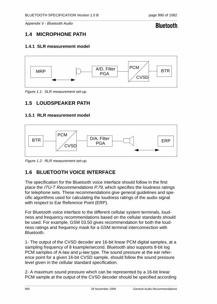
BLUETOOTH SPECIFICATION Version 1.0 B page 990 of 1082
Appendix V - Bluetooth Audio
1.4 MICROPHONE PATH
1.4.1 SLR measurement model
Figure 1.1: SLR measurement set-up.
1.5 LOUDSPEAKER PATH
1.5.1 RLR measurement model
Figure 1.2: RLR measurement set-up.
1.6 BLUETOOTH VOICE INTERFACE
The specification for the Bluetooth voice interface should follow in the first place the ITU-T Recommendations P.79, which specifies the loudness ratings for telephone sets. These recommendations give general guidelines and spe-cific algorithms used for calculating the loudness ratings of the audio signal with respect to Ear Reference Point (ERP).
For Bluetooth voice interface to the different cellular system terminals, loud-ness and frequency recommendations based on the cellular standards should be used. For example, GSM 03.50 gives recommendation for both the loud-ness ratings and frequency mask for a GSM terminal interconnection with Bluetooth.
1- The output of the CVSD decoder are 16-bit linear PCM digital samples, at a sampling frequency of 8 ksample/second. Bluetooth also supports 8-bit log PCM samples of A-law and µ-law type. The sound pressure at the ear refer-ence point for a given 16-bit CVSD sample, should follow the sound pressure level given in the cellular standard specification.
2- A maximum sound pressure which can be represented by a 16-bit linear PCM sample at the output of the CVSD decoder should be specified according
A/D, Filter PCM
CVSD
BTRMRP PGA
PCM
CVSD
D/A, FilterPGA
BTR ERP
990 29 November 1999 General Audio Recommendations

BLUETOOTH SPECIFICATION Version 1.0 B page 991 of 1082
Appendix V - Bluetooth Audio
to the loudness rating, in ITU P.79 and at PGA value of 0 dB. Programmable Gain Amplifiers (PGAs) are used to control the audio level at the terminals by the user. For conversion between various PCM representations: A-law, µ-law and linear PCM, ITU-T G.711, G.712, G.714 give guidelines and PCM value relationships. Zero-code suppression based on ITU-T G.711 is also recom-mended to avoid network mismatches.
General Audio Recommendations 29 November 1999 991

BLUETOOTH SPECIFICATION Version 1.0 B page 992 of 1082
Appendix V - Bluetooth Audio
1.7 FREQUENCY MASK
For interfacing a Bluetooth terminal to a digital cellular mobile terminal, a com-pliance of the CVSD decoder signal to the frequency mask given in the cellular standard, is recommended to guarantee correct function of the speech coders. A recommendation for a frequency mask is given in Table 1.1. Figure 1.3: shows a plot of the frequency mask for Bluetooth (solid line). The GSM fre-quency mask (dotted line) is shown in Figure 1.3: for comparison.
Figure 1.3: Plot of recommended frequency mask for Bluetooth. The GSM send frequency mask is given for comparison (dotted line)
Frequency(Hz)
Upper Limit(dB)
Lower Limit(dB)
50 -20 -
300 4 -12
1000 4 -9
2000 4 -9
3000 4 --9
3400 4 -12
4000 0 -
Table 1.1: Recommended Frequency Mask for Bluetooth
0.1 0.2 0.3 1.0 2.0 3.0 3.4 4.0
8.0
4.0
0.0
-6.0
-9.0
-12.0
0.5
-20.0
f kHz
dBBluetooth
GSM mask
992 29 November 1999 General Audio Recommendations

Appendix VI
BASEBAND TIMERS
This appendix contains a list of all timers defined the Baseband Specification.

BLUETOOTH SPECIFICATION Version 1.0 B page 994 of 1082
Appendix VI - Baseband Timers
994 29 November 1999
BLUETOOTH SPECIFICATION Version 1.0 B page 995 of 1082
Appendix VI - Baseband Timers
CONTENTS
1 Baseband Timers .............................................................................9961.1 LIST OF TIMERS.....................................................................996
1.1.1 inquiryTO.....................................................................996
1.1.2 pageTO .......................................................................996
1.1.3 pagerespTO ................................................................996
1.1.4 inqrespTO....................................................................996
1.1.5 newconnectionTO .......................................................996
1.1.6 supervisionTO .............................................................997
29 November 1999 995

BLUETOOTH SPECIFICATION Version 1.0 B page 996 of 1082
Appendix VI - Baseband Timers
1 BASEBAND TIMERS
This appendix contains a list of all timers defined in this specification. Defini-tions and default values of the timers are listed below.
All timer values are given in slots.
1.1 LIST OF TIMERS
1.1.1 inquiryTO
The inquiryTO defines the number of slots the inquiry substate will last. Its value is determined by an HCI command.
1.1.2 pageTO
The pageTO defines the number of slots the page substate can last before a response is received. Its value is determined by an HCI command.
1.1.3 pagerespTO
In the slave, it defines the number of slots the slave awaits the master’s response, FHS packet, after sending the page acknowledgment ID packet. In the master, pagerespTO defines the number of slots the master should wait for the FHS packet acknowledgment before returning to page substate. Both mas-ter and slave units should use the same value for this timeout, to ensure com-mon page/scan intervals after reaching pagerespTO.
The pagerespTO default value is 8 slots.
1.1.4 inqrespTO
In the inquiry scan substate, when a device triggers on an inquiry, it waits a RAND random number of slots and returns to inquiry scan. The inqRespTO defines the number of slots the device will stay in the inquiry scan substate without triggering on an inquiry after the RAND wait period. The timeout value should preferably be in multiples of an inquiry train period. Upon reaching the inqrespTO, the device returns to CONNECTION or STANDBY state.
The inqrespTO default value is 128 slots.
1.1.5 newconnectionTO
Every time a new connection is started through paging, scanning, master-slave switch or unparking, the master sends a POLL packet as the first packet in the new connection. Transmission and acknowledgment of this POLL packet is used to confirm the new connection. If the POLL packet is not received by the
996 29 November 1999 Baseband Timers

BLUETOOTH SPECIFICATION Version 1.0 B page 997 of 1082
Appendix VI - Baseband Timers
slave or the response packet is not received by the master for newconnecti-onTO number of slots, both the master and the slave will return to the previous substate.
newconnectionTO default value is 32 slots.
1.1.6 supervisionTO
The supervisionTO is used by both the master and slave to monitor link loss. If a device does not receive any packets that pass the HEC check and have the proper AM_ADDR for a period of supervisionTO, it will reset the link supervisi-onTO will work through hold and sniff periods.
The supervisionTO value is determined by an HCI command. At the baseband level a default value that is equivalent to 20 seconds will be used.
Baseband Timers 29 November 1999 997

BLUETOOTH SPECIFICATION Version 1.0 B page 998 of 1082
Appendix VI - Baseband Timers
998 29 November 1999 Baseband Timers

Appendix VII
OPTIONAL PAGING SCHEMES


BLUETOOTH SPECIFICATION Version 1.0 B page 1001 of 1082
Appendix VII - Optional Paging Schemes
CONTENTS
1 General ............................................................................................1003
2 Optional Paging Scheme I .............................................................10042.1 Page.......................................................................................10042.2 Page Scan .............................................................................10062.3 Page Response Procedures ..................................................10062.4 Train Tracing ..........................................................................1007
29 November 1999 1001

BLUETOOTH SPECIFICATION Version 1.0 B page 1002 of 1082
Appendix VII - Optional Paging Schemes
1002 29 November 1999

BLUETOOTH SPECIFICATION Version 1.0 B page 1003 of 1082
Appendix VII - Optional Paging Schemes
1 GENERAL
For the access procedure, several paging schemes may be used. There is one mandatory paging scheme which has to be supported by all Bluetooth devices. This scheme has been described in Baseband Specification Section 10.6 on page 99 In addition to the mandatory scheme, a Bluetooth unit may support one or more optional paging schemes. The method used for page scan is indi-cated in the FHS payload, see Baseband Specification Section 4.4.1.4 on page 56. Three additional optional paging schemes are possible; only optional pag-ing scheme I has been defined yet.
General 29 November 1999 1003

BLUETOOTH SPECIFICATION Version 1.0 B page 1004 of 1082
Appendix VII - Optional Paging Schemes
2 OPTIONAL PAGING SCHEME I
In this section the first optional paging scheme is described which may be used according to the rules specified in Baseband Specification Section 10 on page 95 and LMP Specification Section 3.23 on page 223. The paging code for optional scheme I is 1 (0 is used for the mandatory scheme), see also Base-band Specification Section 4.4.1.4 on page 56
The main difference between the first optional paging scheme and the manda-tory scheme is the construction of the page train sent by the pager. In addition to transmission in the even master slots, the master is transmitting in the odd master slots as well. This allows the slave unit to reduce the scan window.
2.1 PAGE
The same 32 frequencies that are used for transmitting ID-packets in the man-datory paging scheme are used in the optional paging scheme I (for the con-struction of page trains, see Baseband Specification Section 11.3.2 on page 135. The 32 frequencies are also split into an A-train and B train. In contrast to the mandatory scheme, the same 32 frequencies that are used for transmit-ting are also used for reception trials, to catch the response from the addressed device.
The construction of the page train in optional page scheme I differs from the page train in the mandatory scheme in two ways:
• the page train consists of 10 slots, or 6.25 ms
• the first 8 slots of the train are used to transmit the ID packets, the 9th slot is used to send a marker packet, and the 10th slot is used for the return of a slave response
The marker packets precede the return slot, indicating the position where the slave can respond, and with which frequency. For the marker codes M_ID, bit-inverted page access codes are used. If a marker code is received at Tm with frequency fk, a return is expected at nominally Tm+625µs at frequency fk.
Note: The bit-inverted code M_ID to be used as marker code is beneficial for the implementation of the correlators, because the sign of the correlation peak can be used to identify the mark code during page scanning. Still, the transmit-ting party is uniquely identified, since inverted ID packets are not identical to the ID packets for the device with bit-wise inverted LAP.
The frequency ordering in the train and the frequencies used for the marker and receive slots change after every train. After 8 trains, all of which have a different appearance, the entire procedure is repeated. It is, therefore, more appropriate to talk about subtrains, each with length 6.25ms. Eight subtrains form a super-train, which is repeated. An example of a supertrain with the eight subtrains is
1004 29 November 1999 Optional Paging Scheme I

BLUETOOTH SPECIFICATION Version 1.0 B page 1005 of 1082
Appendix VII - Optional Paging Schemes
illustrated in Figure 2.1. The supertrain length is 50ms. In this example, the A-train is assumed with an estimated frequency of f8; as a consequence, the fre-quencies selected for the train range from f0 to f15. The marker codes M_ID are indicated as M; the receive (half) slots are indicated as R.
Figure 2.1: Example of train configuration for optional page scheme I.
Corresponding to the paging modes R0, R1 and R2 of the mandatory scheme, the optional scheme supports the same three modes as described for the man-datory scheme in Baseband Specification Section 10.6.2 on page 99
Since the subtrain length is now 10 slots, the 1.28s interval does not cover a multiple of (sub)trains any longer. Therefore, in contrast to the mandatory scheme, the exchange from A-train to B-train and vice versa is not based on the 1.28s interval, but instead on a multiple number of supertrains. For the R1 and R2 modes, the repetition of a supertrain Nsup is indicated in Table 2.1 below.
mode No SCO link One SCO link (HV3) Two SCO links (HV3)
R1 Nsup=26 Nsup=52 Nsup=77
R2 Nsup=52 Nsup=103 Nsup=154
Table 2.1: Relation between repetition duration of A- and B-trains and paging modes R1 and R2 when SCO links are present
1514131211109876543210
1514
1514
1514131211109876543210
10
10
15141312111098765432
32
10
151413121110987654
54
10
15141312111098 76543210
76
151413121110 9876543210
98
151413121110 9876543210
1110
1514 131211109876543210
1312
32
5432
76
98
1110
1312
M M R R
subtrain 1
subtrain 2
subtrain 3
subtrain 4
subtrain 5
subtrain 6
subtrain 8
subtrain 8
6.25 ms
Optional Paging Scheme I 29 November 1999 1005

BLUETOOTH SPECIFICATION Version 1.0 B page 1006 of 1082
Appendix VII - Optional Paging Schemes
In accordance with the phase input to the hop selection scheme Xp in (EQ 4) on page 135 in the Baseband Specification (Section 11.3.2), the phase input Xp_opt in the optional mode is determined by:
Xp_opt=[koffset_opt + ST(cnt)] mod 32 (EQ A1)
where koffset_opt is determined by the A/B selection and the clock estimation of
the recipient:
koffset_opt = CLKE16-12 + 24 A-train CLKE16-12 + 8 B-train (EQ A2)
and ST is a function determining the structure of the sub- and supertrain:
ST(cnt) = ( cnt mod 160 - 2*INT[ ((cnt mod 160) + 18)/20 ] ) mod 16 (EQ A3)
koffset_opt is determined once at the beginning of the repetition period. The CLKE value as is found at the beginning of the repetition interval is taken (the repetition interval being the interval in which the same supertrain is repeated all the time). As long as no train change takes place, koffset_opt is not updated. cnt is a counter which is reset to zero at the beginning of the repeti-tion interval and is incremented at the half-slot rate (3200 cycles/s)
The first two ID-packets of a train are transmitted in an even numbered slot.
2.2 PAGE SCAN
The basic page scanning is identical to the mandatory scheme except that a scan duration of 9.5 ⋅ 0.625 = 5.9375 ms is sufficient at the slave side.
If a device wants to scan concurrently for the mandatory and optional mode (e.g. after an inquiry response was sent), the device shall try to identify whether the paging party uses the optional scheme after an ID packet was caught. This can be done by train tracing; i.e. the device can determine whether transmis-sion takes place in consecutive slots (optional paging scheme I) or in every over slot (mandatory paging scheme), and/or whether mark codes are sent.
2.3 PAGE RESPONSE PROCEDURES
The page response procedures at the master and slave sides are almost iden-tical to the procedures described in the mandatory mode (see Baseband Spec-ification Section 10.6.4 on page 104). There are two differences:
• The page response routine starts after the transmission and reception of the marker code M_ID
• The ID packet sent by recipient is identical to the frequency in which the marker code was received
For the page response timing, see Figure 2.2 and Figure 2.3.
1006 29 November 1999 Optional Paging Scheme I
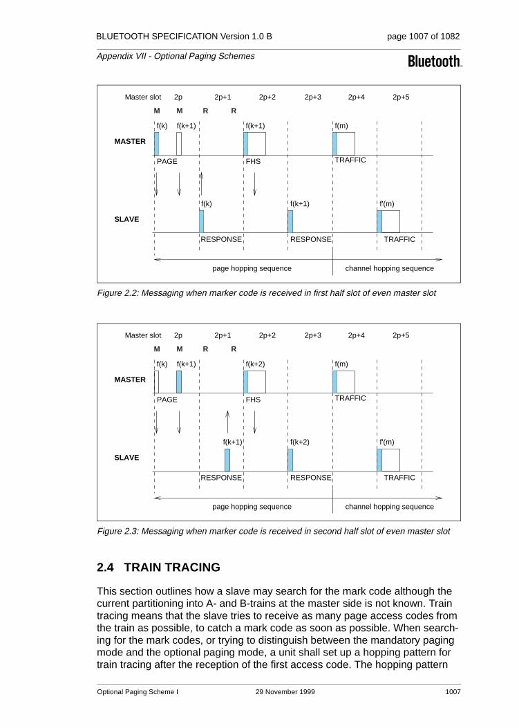
BLUETOOTH SPECIFICATION Version 1.0 B page 1007 of 1082
Appendix VII - Optional Paging Schemes
Figure 2.2: Messaging when marker code is received in first half slot of even master slot
Figure 2.3: Messaging when marker code is received in second half slot of even master slot
2.4 TRAIN TRACING
This section outlines how a slave may search for the mark code although the current partitioning into A- and B-trains at the master side is not known. Train tracing means that the slave tries to receive as many page access codes from the train as possible, to catch a mark code as soon as possible. When search-ing for the mark codes, or trying to distinguish between the mandatory paging mode and the optional paging mode, a unit shall set up a hopping pattern for train tracing after the reception of the first access code. The hopping pattern
f(k)
f(k)
page hopping sequence channel hopping sequence
MASTER
SLAVE
f(k+1) f'(m)
f(m)f(k+1)f(k+1)
PAGE
RESPONSE RESPONSE TRAFFIC
TRAFFIC
2p Master slot 2p+1 2p+2 2p+3 2p+4 2p+5
FHS
M M R R
f(k)
f(k+1)
page hopping sequence channel hopping sequence
MASTER
SLAVE
f(k+2) f'(m)
f(m)f(k+2)f(k+1)
PAGE
RESPONSE RESPONSE TRAFFIC
TRAFFIC
2p Master slot 2p+1 2p+2 2p+3 2p+4 2p+5
FHS
M M R R
Optional Paging Scheme I 29 November 1999 1007

BLUETOOTH SPECIFICATION Version 1.0 B page 1008 of 1082
Appendix VII - Optional Paging Schemes
shall ensure that the transmission and reception is performed with a 50% probability on the same frequency regardless of the actual frequency set (16 frequencies) used for paging.
1008 29 November 1999 Optional Paging Scheme I
Appendix VIII
BLUETOOTH ASSIGNED NUMBERS
This is a living document that lists assigned numbers, codes and identifiers in the Bluetooth standard.

BLUETOOTH SPECIFICATION Version 1.0 B page 1010 of 1082
Bluetooth Assigned Numbers
1010 29 November 1999

BLUETOOTH SPECIFICATION Version 1.0 B page 1011 of 1082
Bluetooth Assigned Numbers
CONTENTS
1 Bluetooth Baseband ......................................................................10121.1 The General- and Device-Specific Inquiry Access
Codes (DIACs).......................................................................10121.2 The Class of Device/Service field ..........................................1012
1.2.1 Major Service Classes...............................................1013
1.2.2 Major Device Classes................................................1014
1.2.3 The Minor Device Class field.....................................1014
1.2.4 Minor Device Class field - Computer Major Class.....1015
1.2.5 Minor Device Class field - Phone Major Class ..........1015
1.2.6 Minor Device Class field - LAN Access Point Major Class ...............................................................1016
1.2.7 Minor Device Class field - Audio Major Class ...........1017
2 Link Manager Protocol (LMP)........................................................10182.1 The Link Manger Version parameter......................................10182.2 The LMP_CompId parameter codes......................................1018
3 Logical Link Control and Adaptation Protocol (L2CAP).............10193.1 Channel Identifiers .................................................................10193.2 Protocol and Service Multiplexor (PSM) ................................1019
4 Service Discovery Protocol (SDP)................................................10204.1 Universally Unique Identifier (UUID) short forms ...................10204.2 Base Universally Unique Identifier (UUID) .............................10204.3 Protocols ................................................................................10214.4 Service classes ......................................................................10224.5 Attribute Identifier codes ........................................................10234.6 Protocol Parameters ..............................................................10244.7 Host Operating Environment Identifiers .................................1024
4.7.1 ClientExecutableURL substitution strings .................1024
4.7.2 IconURL substitution strings......................................1027
5 References......................................................................................1028
6 Terms and Abbreviations ..............................................................1029
7 List of Figures.................................................................................1030
8 List of Tables ..................................................................................1031
29 November 1999 1011

BLUETOOTH SPECIFICATION Version 1.0 B page 1012 of 1082
Bluetooth Assigned Numbers
1 BLUETOOTH BASEBAND
1.1 THE GENERAL- AND DEVICE-SPECIFIC INQUIRY ACCESS CODES (DIACS)
The Inquiry Access Code is the first level of filtering when finding Bluetooth devices and services. The main purpose of defining multiple IACs is to limit the number of responses that are received when scanning devices within range.
The Limited Inquiry Access Code (LIAC) is only intended to be used for limited time periods in scenarios where both sides have been explicitly caused to enter this state, usually by user action. For further explanation of the use of the LIAC, please refer to the Generic Access Profile [7].
In contrast it is allowed to be continuously scanning for the General Inquiry Access Code (GIAC) and respond whenever inquired.
1.2 THE CLASS OF DEVICE/SERVICE FIELD
The Class of Device/Service (CoD) field has a variable format. The format is indicated using the ‘Format Type field’ within the CoD. The length of the Format Type field is variable and ends with two bits different from '11'. The version field starts at the least significant bit of the CoD and may extend upwards.
Figure 1.1: General format of Class of Device/Service
In the ‘format #1’ of the CoD (Format Type field = 00), 11 bits are assigned as a bit-mask (multiple bits can be set) each bit corresponding to a high level generic category of service class. Currently 7 categories are defined. These
# LAP value Usage
0 0x9E8B33 General/Unlimited Inquiry Access Code (GIAC)
1 0x9E8B00 Limited Dedicated Inquiry Access Code (LIAC)
2-63 0x9E8B01-0x9E8B32,0x9E8B34-0x9E8B3F
RESERVED FOR FUTURE USE
Table 1.1: The Inquiry Access Codes
11 Depends on format type
24 bits
Format type field
1012 29 November 1999 Bluetooth Baseband

BLUETOOTH SPECIFICATION Version 1.0 B page 1013 of 1082
Bluetooth Assigned Numbers
are primarily of a ‘public service’ nature. The remaining 11 bits are used to indi-cate device type category and other device-specific characteristics.
Any reserved but otherwise unassigned bits, such as in the Major Service Class field, should be set to 0.
Figure 1.2: The Class of Device/Service field (format type 1). Note the order in which the octets are sent on the air and stored in memory.
1.2.1 Major Service Classes
Bit no Major Service Class
13 Limited Discoverable Mode1
1. As defined in [7]
14 (reserved)
15 (reserved)
16 (reserved)
17 Networking (LAN, Adhoc, …)
18 Rendering (Printing, Speaker, …)
19 Capturing (Scanner, Microphone, …)
20 Object Transfer (v-Inbox, v-Folder, …)
21 Audio (Speaker, Microphone, Headset service, …)
22 Telephony (Cordless telephony, Modem, Headset service, …)
23 Information (WEB-server, WAP-server, …)
Table 1.2: Major Service Classes
bit transmission orderoctet transmission order
When interpreted as alittle endian wordReserved for Service Classes 0 00DMRU�GHYLFH�FODVV Minor device class
Networking
Information
RenderingCapturing
Object TransferAudio
Telephony
Format type
octet 3 octet 2 octet 123 16 15 8 07
11 bits 5 bits 6 bits
Bluetooth Baseband 29 November 1999 1013
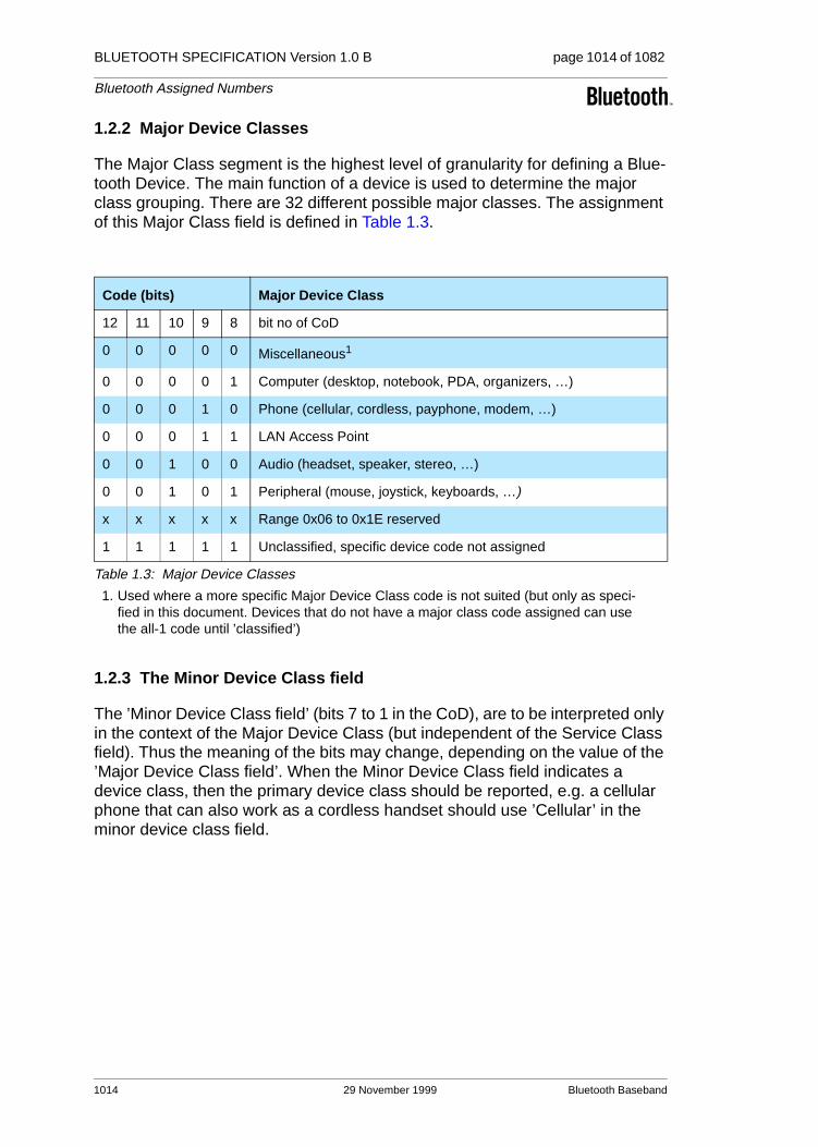
BLUETOOTH SPECIFICATION Version 1.0 B page 1014 of 1082
Bluetooth Assigned Numbers
1.2.2 Major Device Classes
The Major Class segment is the highest level of granularity for defining a Blue-tooth Device. The main function of a device is used to determine the major class grouping. There are 32 different possible major classes. The assignment of this Major Class field is defined in Table 1.3.
1.2.3 The Minor Device Class field
The ’Minor Device Class field’ (bits 7 to 1 in the CoD), are to be interpreted only in the context of the Major Device Class (but independent of the Service Class field). Thus the meaning of the bits may change, depending on the value of the ’Major Device Class field’. When the Minor Device Class field indicates a device class, then the primary device class should be reported, e.g. a cellular phone that can also work as a cordless handset should use ’Cellular’ in the minor device class field.
Code (bits) Major Device Class
12 11 10 9 8 bit no of CoD
0 0 0 0 0 Miscellaneous1
1. Used where a more specific Major Device Class code is not suited (but only as speci-fied in this document. Devices that do not have a major class code assigned can use the all-1 code until ’classified’)
0 0 0 0 1 Computer (desktop, notebook, PDA, organizers, …)
0 0 0 1 0 Phone (cellular, cordless, payphone, modem, …)
0 0 0 1 1 LAN Access Point
0 0 1 0 0 Audio (headset, speaker, stereo, …)
0 0 1 0 1 Peripheral (mouse, joystick, keyboards, …)
x x x x x Range 0x06 to 0x1E reserved
1 1 1 1 1 Unclassified, specific device code not assigned
Table 1.3: Major Device Classes
1014 29 November 1999 Bluetooth Baseband

BLUETOOTH SPECIFICATION Version 1.0 B page 1015 of 1082
Bluetooth Assigned Numbers
1.2.4 Minor Device Class field - Computer Major Class
1.2.5 Minor Device Class field - Phone Major Class
Code (bits) Minor Device Class
7 6 5 4 3 2 bit no of CoD
0 0 0 0 0 0 Unclassified, code for device not assigned
0 0 0 0 0 1 Desktop workstation
0 0 0 0 1 0 Server-class computer
0 0 0 0 1 1 Laptop
0 0 0 1 0 0 Handheld PC/PDA (clam shell)
0 0 0 1 0 1 Palm sized PC/PDA
x x x x x x Range 0x06-0x7F reserved
Table 1.4: Sub Device Class field for the ’Computer’ Major Class
Code (bits) Minor Device Class
7 6 5 4 3 2 bit no of CoD
0 0 0 0 0 0 Unclassified, code not assigned
0 0 0 0 0 1 Cellular
0 0 0 0 1 0 Cordless
0 0 0 0 1 1 Smart phone
0 0 0 1 0 0 Wired modem or voice gateway
x x x x x x Range 0x05-0x7F reserved
Table 1.5: Sub Device Classes for the ’Phone’ Major Class
Bluetooth Baseband 29 November 1999 1015
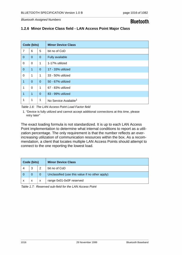
BLUETOOTH SPECIFICATION Version 1.0 B page 1016 of 1082
Bluetooth Assigned Numbers
1.2.6 Minor Device Class field - LAN Access Point Major Class
The exact loading formula is not standardized. It is up to each LAN Access Point implementation to determine what internal conditions to report as a utili-zation percentage. The only requirement is that the number reflects an ever-increasing utilization of communication resources within the box. As a recom-mendation, a client that locates multiple LAN Access Points should attempt to connect to the one reporting the lowest load.
Code (bits) Minor Device Class
7 6 5 bit no of CoD
0 0 0 Fully available
0 0 1 1-17% utilized
0 1 0 17 - 33% utilized
0 1 1 33 - 50% utilized
1 0 0 50 - 67% utilized
1 0 1 67 - 83% utilized
1 1 0 83 - 99% utilized
1 1 1 No Service Available1
1. “Device is fully utilized and cannot accept additional connections at this time, please retry later”
Table 1.6: The LAN Access Point Load Factor field
Code (bits) Minor Device Class
4 3 2 bit no of CoD
0 0 0 Unclassified (use this value if no other apply)
x x x range 0x01-0x0F reserved
Table 1.7: Reserved sub-field for the LAN Access Point
1016 29 November 1999 Bluetooth Baseband

BLUETOOTH SPECIFICATION Version 1.0 B page 1017 of 1082
Bluetooth Assigned Numbers
1.2.7 Minor Device Class field - Audio Major Class
Code (bits) Minor Device Class
7 6 5 4 3 2 bit no of CoD
0 0 0 0 0 0 Unclassified, code not assigned
0 0 0 0 0 1 Device conforms to the Headset profile [9]
x x x x x x Range 0x02-0x7F reserved
Table 1.8: Sub Device Classes for the ’Audio’ Major Class
Bluetooth Baseband 29 November 1999 1017

BLUETOOTH SPECIFICATION Version 1.0 B page 1018 of 1082
Bluetooth Assigned Numbers
2 LINK MANAGER PROTOCOL (LMP)
2.1 THE LINK MANGER VERSION PARAMETER
2.2 THE LMP_COMPID PARAMETER CODES
This is the parameter used in the LMP Version procedure.
Parameter name Assigned values
VersNr 0 Bluetooth LMP 1.0, [2]
1-255 (reserved)
Table 2.1: The LMP Version Parameter Values
Code Company
0 Ericsson Mobile Communications
1 Nokia Mobile Phones
2 Intel Corp.
3 IBM Corp.
4 Toshiba Corp.
5 - 65534 (reserved)
65535 Unassigned. For use in internal and interoperability tests before a Company ID has been assigned. May not be used in products.
Table 2.2: The LMP_CompId parameter codes
1018 29 November 1999 Link Manager Protocol (LMP)
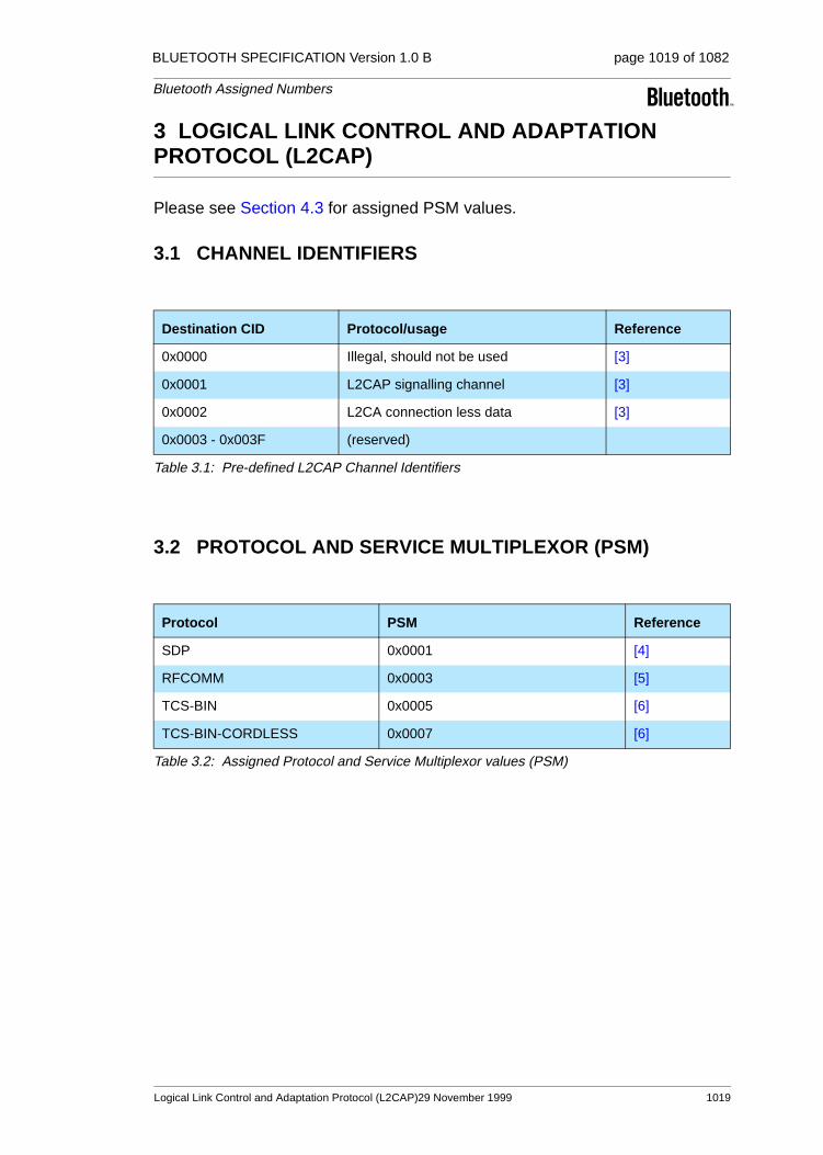
BLUETOOTH SPECIFICATION Version 1.0 B page 1019 of 1082
Bluetooth Assigned Numbers
3 LOGICAL LINK CONTROL AND ADAPTATION PROTOCOL (L2CAP)
Please see Section 4.3 for assigned PSM values.
3.1 CHANNEL IDENTIFIERS
3.2 PROTOCOL AND SERVICE MULTIPLEXOR (PSM)
Destination CID Protocol/usage Reference
0x0000 Illegal, should not be used [3]
0x0001 L2CAP signalling channel [3]
0x0002 L2CA connection less data [3]
0x0003 - 0x003F (reserved)
Table 3.1: Pre-defined L2CAP Channel Identifiers
Protocol PSM Reference
SDP 0x0001 [4]
RFCOMM 0x0003 [5]
TCS-BIN 0x0005 [6]
TCS-BIN-CORDLESS 0x0007 [6]
Table 3.2: Assigned Protocol and Service Multiplexor values (PSM)
Logical Link Control and Adaptation Protocol (L2CAP)29 November 1999 1019

BLUETOOTH SPECIFICATION Version 1.0 B page 1020 of 1082
Bluetooth Assigned Numbers
4 SERVICE DISCOVERY PROTOCOL (SDP)
4.1 UNIVERSALLY UNIQUE IDENTIFIER (UUID) SHORT FORMS
The Bluetooth Service Discovery Protocol (SDP) specification defines a way to represent a range of UUIDs (which are nominally 128-bits) in a shorter form. A reserved range of 232 values can be represented using 32-bits (denoted uuid32). Of these, a sub-range of 216 values can be represented using only 16-bits (denoted uuid16). Any value in the 232 range that is not assigned in this document is reserved pending future revisions of this document. In other words, no value in this range may be used except as specified in this or future revisions of this document. UUID values outside of this range can be allocated as described in [19] for any purpose the allocater desires.
4.2 BASE UNIVERSALLY UNIQUE IDENTIFIER (UUID)
The Base UUID is used for calculating 128-bit UUIDs from ’short UUIDs’ (uuid16 and uuid32) as described in the SDP Specification [4].
Mnemonic UUID
BASE_UUID 00000000-0000-1000-8000-00805F9B34FB
1020 29 November 1999 Service Discovery Protocol (SDP)

BLUETOOTH SPECIFICATION Version 1.0 B page 1021 of 1082
Bluetooth Assigned Numbers
4.3 PROTOCOLS
Mnemonic UUID Name Ref.
SDP uuid16: 0x00011
1. ’Short UUID’
sdp.bt [4]
RFCOMM uuid16: 0x0003 com.bt [5]
TCS-BIN uuid16: 0x0005 tcs.bt [6]
L2CAP uuid16: 0x0100 [3]
IP uuid16: 0x0009
UDP uuid16: 0x0002
TCP uuid16: 0x0004
TCS-AT uuid16: 0x0006 modem
OBEX uuid16: 0x0008 obex
FTP uuid16: 0x000A ftp
HTTP uuid16: 0x000C http
WSP uuid16: 0x000E wsp
Table 4.1: Protocol Universally Unique Identifiers and Names
Service Discovery Protocol (SDP) 29 November 1999 1021

BLUETOOTH SPECIFICATION Version 1.0 B page 1022 of 1082
Bluetooth Assigned Numbers
4.4 SERVICE CLASSES
The Profile column in Table 4.2 indicates which Service Class identifiers that also directly corresponds to a Bluetooth Profile. It is not allowed to use the Ser-vice Class UUID unless the service complies with the specified Profile. These UUIDs might also appear as Profile Identifiers in the BluetoothProfileDescriptorList attribute.
Mnemonic UUID Profile1
1. If the specified Service Class directly and exactly implies a certain Profile, the Profile is indicated here (i.e. for concrete Service Classes). Leave empty for abstract Service Classes.
AbstractName
ServiceDiscoveryServerServiceClassID uuid16: 0x1000
BrowseGroupDescriptorServiceClassID uuid16: 0x1001
PublicBrowseGroup uuid16: 0x1002
SerialPort uuid16: 0x1101 [7] serial.bt
LANAccessUsingPPP uuid16: 0x1102
DialupNetworking uuid16: 0x1103 [13]
IrMCSync uuid16: 0x1104 [17]
OBEXObjectPush uuid16: 0x1105 [16]
OBEXFileTransfer uuid16: 0x1106 [15]
IrMCSyncCommand uuid16: 0x1107 [17]
Headset uuid16: 0x1108 [7] headset
CordlessTelephony uuid16: 0x1109 [10]
Intercom uuid16: 0x1110 [11]
Fax uuid16: 0x1111 [12]
HeadsetAudioGateway uuid16: 0x1112 [7]
PnPInformation uuid16: 0x1200
GenericNetworking uuid16: 0x1201 n/a
GenericFileTransfer uuid16: 0x1202 n/a
GenericAudio uuid16: 0x1203 n/a
GenericTelephony uuid16: 0x1204 n/a
Table 4.2: Service Class Identifiers and Names
1022 29 November 1999 Service Discovery Protocol (SDP)

BLUETOOTH SPECIFICATION Version 1.0 B page 1023 of 1082
Bluetooth Assigned Numbers
4.5 ATTRIBUTE IDENTIFIER CODES
Mnemonic Attribute ID Reference
ServiceRecordHandle 0x0000 [4] Bluetooth Service Discovery Protocol (SDP), Bluetooth SIG
ServiceClassIDList 0x0001
ServiceRecordState 0x0002
ServiceID 0x0003
ProtocolDescriptorList 0x0004
BrowseGroupList 0x0005
LanguageBaseAttributeIDList 0x0006
ServiceInfoTimeToLive 0x0007
ServiceAvailability 0x0008
BluetoothProfileDescriptorList 0x0009
DocumentationURL 0x000A
ClientExecutableURL 0x000B
Icon10 0x000C
IconURL 0x000D
Reserved 0x000E-0x01FF
ServiceName 0x0000 + b1
ServiceDescription 0x0001 + b
ProviderName 0x0002 + b
VersionNumberList 0x0200
ServiceDatabaseState 0x0201
GroupID 0x0200
Remote audio volume control 0x03022 [7]
External network 0x0301 [10]
Service Version 0x0300
Supported Data Stores List 0x0301 [17]
Supported Formats List 0x0303 [16]
Table 4.3: Attribute Identifiers
Service Discovery Protocol (SDP) 29 November 1999 1023
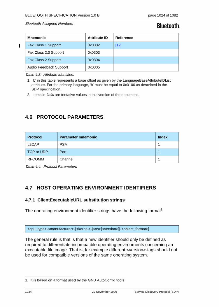
BLUETOOTH SPECIFICATION Version 1.0 B page 1024 of 1082
Bluetooth Assigned Numbers
4.6 PROTOCOL PARAMETERS
4.7 HOST OPERATING ENVIRONMENT IDENTIFIERS
4.7.1 ClientExecutableURL substitution strings
The operating environment identifier strings have the following format1:
The general rule is that is that a new identifier should only be defined as required to differentiate incompatible operating environments concerning an executable file image. That is, for example different <version>-tags should not be used for compatible versions of the same operating system.
Mnemonic Attribute ID Reference
Fax Class 1 Support 0x0302 [12]
Fax Class 2.0 Support 0x0303
Fax Class 2 Support 0x0304
Audio Feedback Support 0x0305
1. ’b’ in this table represents a base offset as given by the LanguageBaseAttributeIDList attribute. For the primary language, ‘b’ must be equal to 0x0100 as described in the SDP specification.
2. Items in italic are tentative values in this version of the document.
Protocol Parameter mnemonic Index
L2CAP PSM 1
TCP or UDP Port 1
RFCOMM Channel 1
Table 4.4: Protocol Parameters
1. It is based on a format used by the GNU AutoConfig tools
<cpu_type>-<manufacturer>-[<kernel>-]<os>[<version>][-<object_format>]
Table 4.3: Attribute Identifiers
1024 29 November 1999 Service Discovery Protocol (SDP)

BLUETOOTH SPECIFICATION Version 1.0 B page 1025 of 1082
Bluetooth Assigned Numbers
Currently defined tags:
CPU-Type ID Description
alpha Digital Alpha* compatible
arm ARM* core or compatible
i86 Any Intel* 80x86-family compatible CPU
i960 Intel* i960 compatible
jvm Java Virtual Machine*
mips MIPS MIPS* compatible
ppc IBM/Motorola PowerPC* compatible
sh3 Hitachi SH-3* compatible
sh4 Hitachi SH-4* compatible
sparc Sun Sparc* compatible
Kernel ID Description
chorus, linux, javaos, os9, qnx, vxworks
<os> An ’OS identifier’ as listed below, might appear in the <kernel> field when the requested OS platform is Java based.
OS+Version-Identifiers
amigaos, beos4.5, ejava, epocc, epoce, epocq, epocs, gnu, jre1.1, jre1.2, macos, macosx, os2, os9, palmos, pjava, pjava1.1, photon, plan9, qnx, rtjava, win95, win98, win2000, wince, winnt4
Object Format Identifiers1
1. Only applicable when the object format is not otherwise uniquely implied by the identifier string.
aout, bout, coff, elf, jar
Manufacturer Identifiers
amiga*, apple*, be*, ericsson*, ibm*, intel*, lucent*, microsoft*, microware*, motorola*,
nokia*, palm*, psion*, qnx*, sun*, symbian*, toshiba*, unknown2
2. Use when no other applies.
Service Discovery Protocol (SDP) 29 November 1999 1025

BLUETOOTH SPECIFICATION Version 1.0 B page 1026 of 1082
Bluetooth Assigned Numbers
For Linux, the ’manufacturer’ field may be used to indicate Linux distribution if so required (in which case <version> indicates the version of the distribution). Otherwise use ’unknown’.
Linux Distribution Identifiers
caldera, debian, dlx, doslinux, linuxpro, linuxware, mandrake, mklinux, redhat, slackware, stampede, suse, turbolinux, yggdrasil
Example Operating Environment Identifier Strings
i86-microsoft-win95 ppc-apple-macos i86-redhat-linux-gnu6
i86-microsoft-win98 m68k-apple-macos ppc-mklinux-linux-gnu
i86-microsoft-winnt4 ppc-apple-macosx
alpha-microsoft-winnt4 i86-apple-macosx
i86-microsoft-win2000 m68k-amiga-amigaos
alpha-microsoft-win2000 ppc-amiga-amigaos
i86-be-beos4.5 jvm-sun-jre1.2
ppc-be-beos4.5 jvm-sun-pjava1.1
arm-symbian-epoc3 jvm-sun-ejava
i86-unknown-linux-gnu m68k-palm-palmos-coff
sh3-microsoft-wince ppc-ibm-vxworks-pjava1.2
arm-microsoft-wince sparc-sun-javaos-jre1.2
1026 29 November 1999 Service Discovery Protocol (SDP)

BLUETOOTH SPECIFICATION Version 1.0 B page 1027 of 1082
Bluetooth Assigned Numbers
4.7.2 IconURL substitution strings
The IconURL operating environment identifier strings have the following general format:
The optional tag ’m’ indicates monochrome or grayscale. The host is free to try to match/request any graphics file format as indicated by a <file_format> tag, however at a minimum files conforming to the Portable Network Graphic stan-dard [18] should be made available at the resulting URL (indicated by <file_format>=png)2.
Currently defined IconURL Icon format identifier strings:
<horizontal_pixels>x<vertical_pixels>x<color_depth>[m].<file_format>
2. The use of PNG, and whether a subset of PNG should be required, is currently pending fur-ther investigation.
File format tag Description
png Portable Network Graphics [18]
gif Graphics Interchange File format
bmp Windows bitmap
Example Icon format Identifier Strings
32x32x8.png 256 color 32 by 32 icon (or 255 colors + transparent)
16x16x8.png
16x16x1m.png Black and white (or monochrome + transparent)
10x10x2m.png 4 gray-scales
Service Discovery Protocol (SDP) 29 November 1999 1027

BLUETOOTH SPECIFICATION Version 1.0 B page 1028 of 1082
Bluetooth Assigned Numbers
5 REFERENCES
[1] Bluetooth Baseband Specification, Bluetooth SIG
[2] Bluetooth Link Manager Specification, Bluetooth SIG
[3] Logical Link Control and Adaptation Protocol Specification, Bluetooth SIG
[4] Bluetooth Service Discovery Protocol (SDP), Bluetooth SIG
[5] RFCOMM with TS 07.10, Bluetooth SIG
[6] Bluetooth Telephony Control Specification / TCS Binary, Bluetooth SIG
[7] Generic Access Profile, Bluetooth SIG
[8] Serial Port Profile, Bluetooth SIG
[9] Headset Profile, Bluetooth SIG
[10] Cordless Telephony Profile, Bluetooth SIG
[11] Intercom Profile, Bluetooth SIG
[12] Fax Profile, Bluetooth SIG
[13] Dial-up Networking Profile, Bluetooth SIG
[14] IrDA Interoperability, Bluetooth SIG
[15] File Transfer Profile, Bluetooth SIG
[16] Object Push Profile, Bluetooth SIG
[17] Synchronization Profile, Bluetooth SIG
[18] Portable Network Graphics (PNG), http://www.w3.org/Graphics/PNG
[19] UUIDs and GUIDs, P. J. Leach et al, http://www.ietf.org/internet-drafts/draft-leach-uuids-guids-01.txt
1028 29 November 1999 References

BLUETOOTH SPECIFICATION Version 1.0 B page 1029 of 1082
Bluetooth Assigned Numbers
6 TERMS AND ABBREVIATIONS
LMP Link Management Protocol
L2CA Logical Link Control and Adaptation, protocol multiplexer layer for Bluetooth
MTU Maximum Transmission Unit
SAP Service Access Points
Baseband Baseband Protocol
Service Discovery The ability to discover the capability of connecting devices or hosts.
PnP Plug and Play
SAR Segmentation and Reassembly
IP Internet Protocol
IrDA InfraRed Data Association
PPP Point-to-Point Protocol
IETF Internet Engineering Task Force
RFC Request For Comments
Terms and Abbreviations 29 November 1999 1029

BLUETOOTH SPECIFICATION Version 1.0 B page 1030 of 1082
Bluetooth Assigned Numbers
7 LIST OF FIGURES
Figure 1.1: General format of Class of Device/Service............................1012Figure 1.2: The Class of Device/Service field (format type 1)..................1013
1030 29 November 1999 List of Figures

BLUETOOTH SPECIFICATION Version 1.0 B page 1031 of 1082
Bluetooth Assigned Numbers
8 LIST OF TABLES
Table 1.1: The Inquiry Access Codes .....................................................1012Table 1.2: Major Service Classes ...........................................................1013Table 1.3: Major Device Classes ............................................................1014Table 1.4: Sub Device Class field for the ’Computer’ Major Class .........1015Table 1.5: Sub Device Classes for the ’Phone’ Major Class...................1015Table 1.6: The LAN Access Point Load Factor field ...............................1016Table 1.7: Reserved sub-field for the LAN Access Point ........................1016Table 1.8: Sub Device Classes for the ’Audio’ Major Class....................1017Table 2.1: The LMP Version Parameter Values ......................................1018Table 2.2: The LMP_CompId parameter codes......................................1018Table 3.1: Pre-defined L2CAP Channel Identifiers .................................1019Table 3.2: Assigned Protocol and Service Multiplexor values (PSM) .....1019Table 4.1: Protocol Universally Unique Identifiers and Names...............1021Table 4.2: Service Class Identifiers and Names .....................................1022Table 4.3: Attribute Identifiers .................................................................1023Table 4.4: Protocol Parameters ..............................................................1024
List of Tables 29 November 1999 1031

BLUETOOTH SPECIFICATION Version 1.0 B page 1032 of 1082
Bluetooth Assigned Numbers
1032 29 November 1999 List of Tables

Appendix IX
MESSAGE SEQUENCE CHARTS
Between Host and Host Controller/Link Manager
This document shows examples of inter-working between HCI Commands and LM Protocol Data Units in form of message sequence charts. It helps to understand and to correctly use the HCI Commands.

BLUETOOTH SPECIFICATION Version 1.0 B page 1034 of 1082
Message Sequence Charts
1034 29 November 1999

BLUETOOTH SPECIFICATION Version 1.0 B page 1035 of 1082
Message Sequence Charts
CONTENTS
1 Introduction ....................................................................................1037
2 Services without connection request...........................................10382.1 Remote Name Request..........................................................10382.2 One-Time Inquiry ...................................................................10392.3 Periodic Inquiry ......................................................................1040
3 ACL connection establishment and detachment ........................10423.1 ACL Connection Request phase............................................10433.2 ACL Connection Setup phase................................................1045
3.2.1 Pairing .......................................................................10453.2.2 Authentication............................................................1047
3.3 Encryption and Connection Setup Complete .........................10473.4 ACL Disconnection.................................................................1048
4 Optional activities after ACL Connection establishment ...........10504.1 Authentication Requested......................................................10504.2 Set Connection Encryption.....................................................10514.3 Change Connection Link Key.................................................10524.4 Master Link Key .....................................................................10534.5 Read Remote Supported Features ........................................10554.6 Read Clock Offset ..................................................................10554.7 Read Remote Version Information.........................................10564.8 QoS Setup .............................................................................10574.9 Switch Role ............................................................................1057
5 SCO Connection establishment and detachment .......................10595.1 SCO Connection setup ..........................................................1059
5.1.1 Master activates the SCO Connection setup ............10595.1.2 Slave activates the SCO Connection setup ..............1060
5.2 SCO Disconnection................................................................1060
6 Special modes: sniff, hold, park ...................................................10626.1 Sniff Mode..............................................................................10626.2 Hold Mode..............................................................................10636.3 Park Mode..............................................................................1065
6.3.1 Enter park mode........................................................10656.3.2 Exit Park Mode..........................................................1066
7 Buffer management, flow control .................................................1068
8 Loopback Mode..............................................................................10708.1 Local Loopback Mode............................................................10708.2 Remote Loopback Mode........................................................1072
29 November 1999 1035

BLUETOOTH SPECIFICATION Version 1.0 B page 1036 of 1082
Message Sequence Charts
9 List of Acronyms and Abbreviations ...........................................1073
10 List of Figures ................................................................................1074
11 List of Tables ..................................................................................1075
12 References......................................................................................1076
1036 29 November 1999

BLUETOOTH SPECIFICATION Version 1.0 B page 1037 of 1082
Message Sequence Charts
1 INTRODUCTION
The goal of this document is to show the interworkings of HCI-Commands and LM-PDUs. It focuses on the message sequence charts for the procedures specified in [3] “Bluetooth Host Controller Interface Functional Specification” with regard to LM Procedures from [2] “Link Manager Protocol”.
We illustrate here the most useful scenarios, but we do not cover all possible alternatives. Furthermore, the message sequence charts do not consider the transfer error over Air Interface or Host Interface. In all message sequence charts it is assumed that all events are not masked, so the Host Controller will not filter out any events.
Notation used in the message sequence charts:
Box:
• Replaces a group of transactions
• Indicates the start of a procedure or a sub-scenario
Note: in a message sequence chart where several sub-scenarios exist, the sub-scenarios can be executed optionally, consequently, exclusively or inde-pendently from each other.
Hexagon:
• Indicates a condition that is needed to start the transaction below this hexagon
Arrow:
• Represents a message, signal or transaction
Comment:
• “/* … */” indicates editor comments
Introduction 29 November 1999 1037

BLUETOOTH SPECIFICATION Version 1.0 B page 1038 of 1082
Message Sequence Charts
2 SERVICES WITHOUT CONNECTION REQUEST
2.1 REMOTE NAME REQUEST
The service Remote Name Request is used to find out the name of the remote BT Device without an explicit ACL Connection request.
Sending an HCI_Remote_Name_Request (BD_ADDR, Page_Scan_Repetition_Mode, Page_Scan_Mode, Clock_Offset), the Host expects that its local BT Device will automatically try to connect to the remote BT Device (with the specified BD_ADDR). Then the local BT Device should try to get the name, to disconnect, and finally to return the name of the remote BT Device back to the Host (see Figure 2.1 Remote Name Request: sub-scenario 1).
Note: if an ACL Connection already exists (see Figure 2.1 Remote Name Request: sub-scenario 2), the Remote Name Request procedure will be executed like an optional service. No Paging and no ACL Detachment need to be done.
1038 29 November 1999 Services without connection request

BLUETOOTH SPECIFICATION Version 1.0 B page 1039 of 1082
Message Sequence Charts
Figure 2.1: Remote Name Request
2.2 ONE-TIME INQUIRY
Inquiry is used to detect and collect nearby BT Devices. When receiving the command HCI_Inquiry (LAP, Inquiry_Length, Num_Responses), HC will start the baseband inquiry procedure with an Inquiry Access Code (derived from the specified LAP) and Inquiry Length. When Inquiry Responses are received, HC will filter out and then return the information related to the found BT Devices using one or several Inquiry Result events (Num_Responses, BD_ADDR[I], Page_Scan_Repetition_Mode[i], Page_Scan_Period_Mode[i], Page_Scan_Mode[i], Class_Of_Device[i], Clock_Offset[i]) to the Host.
LMP_name_req (offset)
LMP_name_req (offset)
...
(offset, name_length, name_offset)
LMP_name_res
(offset, name_length, name_offset)
LMP_name_res
(Status, BD_ADDR,Remote_Name)
(Status, BD_ADDR,Remote_Name)
(Status, Num_Cmd,Cmd_OpCode)
HCI Command Status event
Host-A HC/LM-A HC/LM-B Host-B
(BD_ADDR, ..)HCI_Remote_Name_Request
"Page" (ID-Packet)
"Page Response" (ID-Packet)
FHS (BD_ADDR, CoD, ..)
"FHS-Ack" (ID-Packet)
LMP_detach (reason)
/* LMP_name_req/-res canbe repeated several timesdependent on the namelength */
/* LMP_name_req/-rescan be repeated severaltimes dependent on thename length */
Sub-scenario 1: No ACL Connection existed => create a temporary ACL Connection
Sub-scenario 2: ACL Connection already exists => No temporary ACL Connection needed
...
HCI Remote Name Request Complete event
HCI Remote Name Request Complete event
Services without connection request 29 November 1999 1039

BLUETOOTH SPECIFICATION Version 1.0 B page 1040 of 1082
Message Sequence Charts
The filtering of found BT Devices is specified in HCI_Set_Event_Filter (Filter_Type, Filter_Condition_Type, Condition) with the Filter_Type = Inquiry Result. When the Inquiry procedure is completed, Inquiry Complete event (Status, Num_Responses) must be returned to the Host. Otherwise, the com-mand HCI_Inquiry_Cancel( ) will be used to directly stop the inquiry procedure.
Figure 2.2: One-Time Inquiry
2.3 PERIODIC INQUIRY
Periodic inquiry is needed when the inquiry procedure is to be repeated periodically. Receipt of the command HCI_Periodic_Inquiry_Mode (Max_Period_Length, Min_Period_Length, LAP, Inquiry_Length, Num_Responses) HC will start the periodic Inquiry Mode with the specified
(Num_Cmd, Cmd_OpCode,Status)
HCI Command Complete event
(Status, Num_Cmd,Cmd_OpCode)
HCI Command Status event
Host-AHC/LM-AMaster
Slave - 1 Slave - n
(LAP, Inq_Length, Num_Res)HCI_Inquiry
"Inquiry" (ID-Packet)
FHS (BD_ADDR, CoD, ..)
(Num_Res, BD_ADDR[i], ..)HCI Inquiry Result event
Sub-scenario 2: explicit stop using HCI_Inquiry_Cancel ()
...
"Inquiry" (ID-Packet)
/* Random Access0-1023 */
"Inquiry" (ID-Packet)
/* 0 - n times */
HCI_Inquiry_Cancel ()/* stop inquiry */
Sub-scenario 3: stop when Inq_Length expired or Num_Res reached
(Status, Num_Res)HCI Inquiry Complete event
/* Random Access0-1023 */
Sub-scenario 1: Collection of BT Devices during Inquiry Procedure
"Inquiry" (ID-Packet)
FHS (BD_ADDR, CoD, ..)
1040 29 November 1999 Services without connection request

BLUETOOTH SPECIFICATION Version 1.0 B page 1041 of 1082
Message Sequence Charts
parameters Max_Period_Length, Min_Period_Length, Inquiry_Access_code (derived from LAP) and Inquiry_Length. As in the one-time Inquiry procedure, only BT Devices that are specified in the HCI_Set_Event_Filter (Filter_Type, Filter_Condition_Type, Condition) with the Filter_Type = Inquiry Result will not be filtered out. Therefore, in the inquiry cycle, one or several Inquiry Result events (Num_Responses, BD_ADDR[i], Page_Scan_Repetition_Mode[i], Page_Scan_Period_Mode[i], Page_Scan_Mode[i], Class_Of_Device[i], Clock_Offset[i]) and Inquiry Complete event (Status, Num_Responses) will be returned to the Host with one, or a list of, found BT Devices. The periodic Inquiry can be stopped using HCI_Exit_Periodic_Inquiry_Mode( ).
Figure 2.3: Periodic Inquiry
HCI Command Complete event(Num_Cmd, Cmd_OpCode,
Status)
HCI Command Complete event(Num_Cmd, Cmd_OpCode,
Status)
HCI_Exit_Periodic_Inquiry_Mode ()
Host-AHC/LM-AMaster
Slave - 1 Slave - n
(Max_Period, Min_Period, ..)
HCI_Periodic_Inquiry_Mode
"Inquiry" (ID-Packet)
FHS (BD_ADDR, CoD, ..)
(Num_Res, BD_ADDR[i], ..)HCI Inquiry Result event
Sub-scenario 2: explicit exit Periodic Inquiry Mode using HCI_Exit_Inquiry_Mode ()
...
"Inquiry" (ID-Packet)
/* Random Access0-1023 */
"Inquiry" (ID-Packet)
"Inquiry" (ID-Packet)
FHS (BD_ADDR, CoD, ..)
/* 0 - n times */
/* stop periodicinquiry */
Sub-scenario 3: when Inq_Length expired or Num_Res reached => exit this Inquiry Period
(Status, Num_Res)HCI Inquiry Complete event
/* Random Access0-1023 */
Sub-scenario 1: Collection of BT Devices during an Inquiry Period
Services without connection request 29 November 1999 1041

BLUETOOTH SPECIFICATION Version 1.0 B page 1042 of 1082
Message Sequence Charts
3 ACL CONNECTION ESTABLISHMENT AND DETACHMENT
The overview of the ACL Connection establishment and detachment is shown in Figure 3.1 Overview of ACL Connection establishment and detachment.
Figure 3.1: Overview of ACL Connection establishment and detachment
Page/PageRes
Pairing
Role Change
Authentication
Encryption
Setup-Complete
OptionalActivities
ACL-Disconnection
ACL-Connection-Request
1042 29 November 1999 ACL connection establishment and detachment
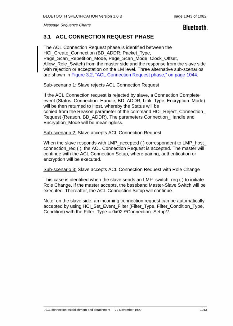
BLUETOOTH SPECIFICATION Version 1.0 B page 1043 of 1082
Message Sequence Charts
3.1 ACL CONNECTION REQUEST PHASE
The ACL Connection Request phase is identified between the HCI_Create_Connection (BD_ADDR, Packet_Type, Page_Scan_Repetition_Mode, Page_Scan_Mode, Clock_Offset, Allow_Role_Switch) from the master side and the response from the slave side with rejection or acceptation on the LM level. Three alternative sub-scenarios are shown in Figure 3.2, “ACL Connection Request phase,” on page 1044.
Sub-scenario 1: Slave rejects ACL Connection Request
If the ACL Connection request is rejected by slave, a Connection Complete event (Status, Connection_Handle, BD_ADDR, Link_Type, Encryption_Mode) will be then returned to Host, whereby the Status will be copied from the Reason parameter of the command HCI_Reject_Connection_Request (Reason, BD_ADDR). The parameters Connection_Handle and Encryption_Mode will be meaningless.
Sub-scenario 2: Slave accepts ACL Connection Request
When the slave responds with LMP_accepted ( ) correspondent to LMP_host_connection_req ( ), the ACL Connection Request is accepted. The master will continue with the ACL Connection Setup, where pairing, authentication or encryption will be executed.
Sub-scenario 3: Slave accepts ACL Connection Request with Role Change
This case is identified when the slave sends an LMP_switch_req ( ) to initiate Role Change. If the master accepts, the baseband Master-Slave Switch will be executed. Thereafter, the ACL Connection Setup will continue.
Note: on the slave side, an incoming connection request can be automatically accepted by using HCI_Set_Event_Filter (Filter_Type, Filter_Condition_Type, Condition) with the Filter_Type = 0x02 /*Connection_Setup*/.
ACL connection establishment and detachment 29 November 1999 1043
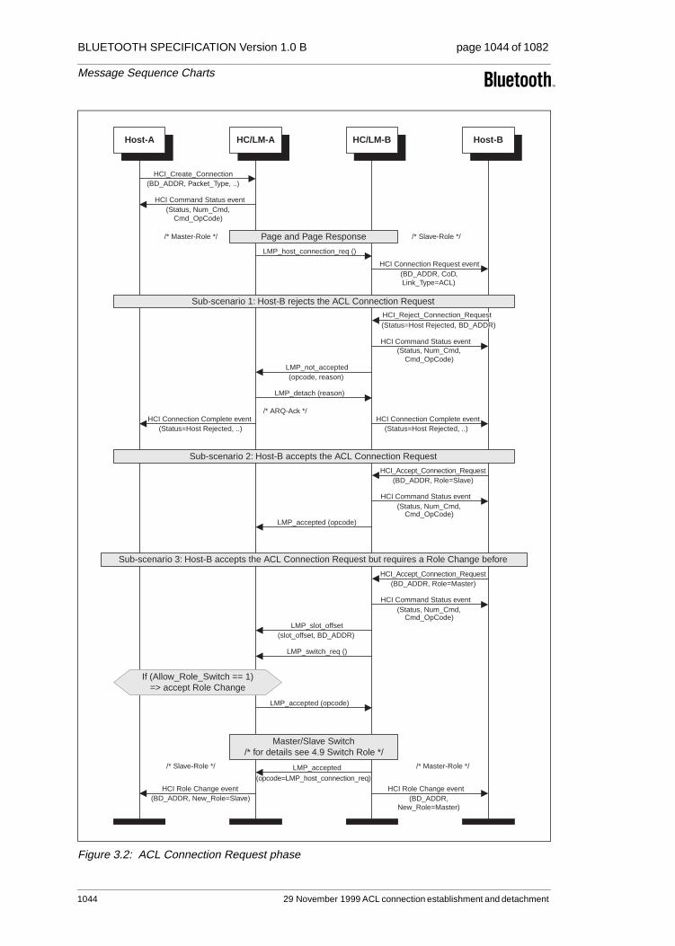
BLUETOOTH SPECIFICATION Version 1.0 B page 1044 of 1082
Message Sequence Charts
Figure 3.2: ACL Connection Request phase
(Status, Num_Cmd,Cmd_OpCode)
HCI Command Status event
(opcode=LMP_host_connection_req)
LMP_accepted
(Status, Num_Cmd,Cmd_OpCode)
HCI Command Status event
HCI_Accept_Connection_Request(BD_ADDR, Role=Master)
HCI_Accept_Connection_Request(BD_ADDR, Role=Slave)
(Status, Num_Cmd,Cmd_OpCode)
HCI Command Status event
HCI Connection Complete event(Status=Host Rejected, ..)
HCI Connection Complete event(Status=Host Rejected, ..)
HCI Connection Request event(BD_ADDR, CoD,Link_Type=ACL)
(Status, Num_Cmd,Cmd_OpCode)
HCI Command Status event
Host-A HC/LM-A HC/LM-B Host-B
(BD_ADDR, Packet_Type, ..)HCI_Create_Connection
(opcode, reason)LMP_not_accepted
LMP_host_connection_req ()
/* ARQ-Ack */
Sub-scenario 2: Host-B accepts the ACL Connection Request
Page and Page Response
Sub-scenario 1: Host-B rejects the ACL Connection Request
LMP_detach (reason)
LMP_accepted (opcode)
Sub-scenario 3: Host-B accepts the ACL Connection Request but requires a Role Change before
LMP_switch_req ()
/* Master-Role */ /* Slave-Role */
LMP_accepted (opcode)
Master/Slave Switch/* for details see 4.9 Switch Role */
(BD_ADDR,New_Role=Master)
HCI Role Change event(BD_ADDR, New_Role=Slave)
HCI Role Change event
/* Slave-Role */ /* Master-Role */
If (Allow_Role_Switch == 1)=> accept Role Change
(slot_offset, BD_ADDR)LMP_slot_offset
HCI_Reject_Connection_Request(Status=Host Rejected, BD_ADDR)
1044 29 November 1999 ACL connection establishment and detachment

BLUETOOTH SPECIFICATION Version 1.0 B page 1045 of 1082
Message Sequence Charts
3.2 ACL CONNECTION SETUP PHASE
If the ACL Connection Request phase was successful, the ACL Connection Setup phase will start, with the goal of executing security procedures like pair-ing, authentication and encryption. The ACL Connection Setup phase is suc-cessfully finished when LMP_setup_complete ( ) is exchanged and the Connection Complete event (Status=0x00, Connection_Handle, BD_ADDR, Link_Type, Encryption_Mode) is sent to the Host.
3.2.1 Pairing
If authentication is required and the BT Devices to be connected don’t have a common link key, the pairing procedure on LM Level will be executed using the PIN Input from Host. During the pairing, the authentication- and link key cre-ation procedures will be done. Note: the created Link Key can be stored either in the BT Device or in the Host.
ACL connection establishment and detachment 29 November 1999 1045

BLUETOOTH SPECIFICATION Version 1.0 B page 1046 of 1082
Message Sequence Charts
Figure 3.3: ACL Connection setup with pairing
LMP_au_rand (rand_nr)
(Num_Cmd, Cmd_OpCode,Status)
HCI Command Complete event
(Num_Cmd, Cmd_OpCode,HCI Command Complete event
(BD_ADDR)
(BD_ADDR, Link_Key)HCI Link Key Notification event
(BD_ADDR, Link_Key)HCI Link Key Notification event
(Num_Cmd, Cmd_OpCode,Status)
HCI Command Complete event
Host-AHC/LM-AMaster
HC/LM-BSlave
Host-B
LMP_features_req (features)
Pairing
(BD_ADDR)HCI Link Key Request event
LMP_accepted (opcode)
(BD_ADDR, PIN_Length, PIN)HCI_PIN_Code_Request_Reply
(BD_ADDR)HCI PIN Code Request event
LMP_sres (auth_res)
LMP_features_res (features)
If (Auth_Enable==1)AND(Link Keymissed) => Link Key required
ACL Connection Request established
If no Link Key from Host=> PIN required
(BD_ADDR)HCI PIN Code Request event
(BD_ADDR, PIN_Length, PIN)HCI_PIN_Code_Request_Reply
LMP_in_rand (rand_nr)
LMP_au_rand (rand_nr)
LMP_sres (auth_res)
LMP_comb_key (rand_nr)
LMP_comb_key (rand_nr)
User'sPIN-Input
LMP_au_rand (rand_nr)
LMP_sres (auth_res)
LMP_au_rand (rand_nr)
LMP_sres (auth_res)
/* Mutual Authenticationbased on the Init-Key */
/* Mutual Authenticationbased on the new
combination key */
_Request_Negative_ReplyHCI_Link_Key
Status)
User'sPIN-Input
1046 29 November 1999 ACL connection establishment and detachment
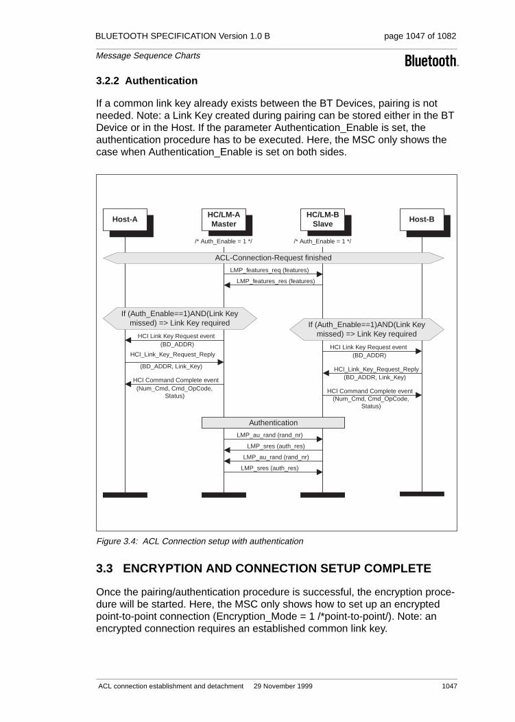
BLUETOOTH SPECIFICATION Version 1.0 B page 1047 of 1082
Message Sequence Charts
3.2.2 Authentication
If a common link key already exists between the BT Devices, pairing is not needed. Note: a Link Key created during pairing can be stored either in the BT Device or in the Host. If the parameter Authentication_Enable is set, the authentication procedure has to be executed. Here, the MSC only shows the case when Authentication_Enable is set on both sides.
Figure 3.4: ACL Connection setup with authentication
3.3 ENCRYPTION AND CONNECTION SETUP COMPLETE
Once the pairing/authentication procedure is successful, the encryption proce-dure will be started. Here, the MSC only shows how to set up an encrypted point-to-point connection (Encryption_Mode = 1 /*point-to-point/). Note: an encrypted connection requires an established common link key.
LMP_au_rand (rand_nr)
LMP_sres (auth_res)
LMP_au_rand (rand_nr)
LMP_sres (auth_res)
HCI Command Complete event(Num_Cmd, Cmd_OpCode,
Status)
HCI Command Complete event(Num_Cmd, Cmd_OpCode,
Status)
Host-AHC/LM-AMaster
HC/LM-BSlave
Host-B
LMP_features_req (features)
(BD_ADDR, Link_Key)
HCI_Link_Key_Request_Reply
Authentication
(BD_ADDR)HCI Link Key Request event
LMP_features_res (features)
If (Auth_Enable==1)AND(Link Keymissed) => Link Key required
ACL-Connection-Request finished
/* Auth_Enable = 1 */ /* Auth_Enable = 1 */
If (Auth_Enable==1)AND(Link Keymissed) => Link Key required
(BD_ADDR)HCI Link Key Request event
(BD_ADDR, Link_Key)HCI_Link_Key_Request_Reply
ACL connection establishment and detachment 29 November 1999 1047

BLUETOOTH SPECIFICATION Version 1.0 B page 1048 of 1082
Message Sequence Charts
Figure 3.5: Encryption and Setup complete
3.4 ACL DISCONNECTION
At any time, an established ACL Connection can be detached by an HCI_Disconnect (Connection_Handle, Reason). If one or several SCO Connections exist, they must first be detached before the ACL Connection can be released.
Note: the disconnection procedure is one-sided and doesn’t need an explicit acknowledgment from the remote LM. So the ARQ Acknowledgment from the LC is needed, to ensure that the remote LM has received the LMP_detach (reason).
LMP_setup_complete ()
HCI Connection Complete event HCI Connection Complete event
(key_size)LMP_encryption_key_size_req
Host-AHC/LM-AMaster
HC/LM-BSlave
Host-B
ACL Setup Complete
LMP_accepted (opcode)
(encr_mode)LMP_encryption_mode_req
Pairing/Authentication finished
LMP_setup_complete ()
/* Encr_Mode=Point-to-Point */ /* Encr_Mode=Point-to-Point */
Encryption
LMP_accepted (opcode)
(rand_nr)LMP_start_encryption_req
LMP_accepted (opcode)
(Status=0x00, ConHandle, BD_ADDR, ..) (Status=0x00, ConHandle, BD_ADDR, ..)
1048 29 November 1999 ACL connection establishment and detachment

BLUETOOTH SPECIFICATION Version 1.0 B page 1049 of 1082
Message Sequence Charts
Figure 3.6: ACL Disconnection
/* ARQ-Ack */
HCI Command Status Event(Status, Num_Cmd,
Cmd_OpCode)
Host-A HC/LM-A HC/LM-B Host-B
(ConHandle, Reason)HCI_Disconnect
ACL Connection established
LMP_detach (reason)
HCI Disconnection Complete event(Status=0x00, ConHandle', Reason)
HCI Disconnection Complete event(Status=0x00, ConHandle, Reason)
ACL connection establishment and detachment 29 November 1999 1049

BLUETOOTH SPECIFICATION Version 1.0 B page 1050 of 1082
Message Sequence Charts
4 OPTIONAL ACTIVITIES AFTER ACL CONNECTION ESTABLISHMENT
4.1 AUTHENTICATION REQUESTED
Authentication can be explicitly executed at any time after an ACL Connection has been established. If the Link Key was missed in HC/LM, the Link Key will be required from the Host, as in the authentication procedure (see 3.2.2).
Note: if the HC/LM and the Host don’t have the Link Key a PIN Code Request event will be sent to the Host to request a PIN Code for pairing. A procedure identical to ACL Connection Setup with Pairing (see 3.2.1) will be used.
Figure 4.1: Authentication Requested
HCI Authentication Complete event
(Status=0x00, ConHandle)
(Num_Cmd, Cmd_OpCode,Status)
HCI Command Complete event
(Num_Cmd, Cmd_OpCode,Status)
HCI Command Complete event
(Status, Num_Cmd,Cmd_OpCode)
HCI Command Status event
(ConHandle)HCI_Authentication_Requested
Host-A HC/LM-A HC/LM-A Host-B
(BD_ADDR, Link_Key)HCI_Link_Key_Request_Reply
(BD_ADDR)HCI Link Key Request event
LMP_sres (auth_res)
LMP_au_rand (rand_nr)
If Link Key missed=> Link Key request to Host
ACL Connection established
If Link Key missed=> Link Key request to Host
(BD_ADDR)HCI Link Key Request event
(BD_ADDR, Link_Key)HCI_Link_Key_Request_Reply
1050 29 November 1999 Optional activities after ACL Connection
BLUETOOTH SPECIFICATION Version 1.0 B page 1051 of 1082
Message Sequence Charts
4.2 SET CONNECTION ENCRYPTION
Using the command HCI_Set_Connection_Encryption (Connection_Handle, Encryption_Enable), the Host is able to switch the encryption of a connection with the specified Connection_Handle to ON/OFF. This command can be applied on both the master- and slave sides (only the master side is shown in Figure 4.2 Set Connection Encryption). If this command occurs on the slave side, the only difference is that LMP_encryption_mode_req (encryption_mode) will be sent from the HC/LM Slave. LMP_encryption_key_size_req (key_size) and LMP_start_encryption_req (rand_nr) will still be requested from the HC/LM master.
Optional activities after ACL Connection establishment 29 November 1999 1051
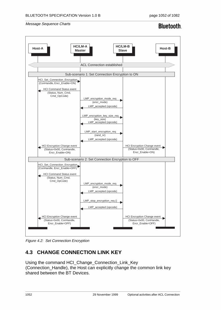
BLUETOOTH SPECIFICATION Version 1.0 B page 1052 of 1082
Message Sequence Charts
Figure 4.2: Set Connection Encryption
4.3 CHANGE CONNECTION LINK KEY
Using the command HCI_Change_Connection_Link_Key (Connection_Handle), the Host can explicitly change the common link key shared between the BT Devices.
(Status, Num_Cmd,Cmd_OpCode)
HCI Command Status event
HCI Encryption Change event(Status=0x00, ConHandle,
Encr_Enable=ON)
HCI Encryption Change event(Status=0x00, ConHandle,
Encr_Enable=ON)
(Status, Num_Cmd,Cmd_OpCode)
HCI Command Status event
HCI Encryption Change event(Status=0x00, ConHandle,
Encr_Enable=OFF)
HCI Encryption Change event(Status=0x00, ConHandle,
Encr_Enable=OFF)
Host-AHC/LM-AMaster
HC/LM-BSlave
Host-B
Sub-scenario 2: Set Connection Encryption to OFF
LMP_accepted (opcode)
(encr_mode)LMP_encryption_mode_req
ACL Connection established
Sub-scenario 1: Set Connection Encryption to ON
LMP_encryption_key_size_req(key_size)
LMP_accepted (opcode)
(rand_nr)LMP_start_encryption_req
LMP_accepted (opcode)
HCI_Set_Connection_Encryption(ConHandle, Encr_Enable=ON)
HCI_Set_Connection_Encryption(ConHandle, Encr_Enable=OFF)
LMP_accepted (opcode)
(encr_mode)LMP_encryption_mode_req
LMP_stop_encryption_req ()
LMP_accepted (opcode)
1052 29 November 1999 Optional activities after ACL Connection

BLUETOOTH SPECIFICATION Version 1.0 B page 1053 of 1082
Message Sequence Charts
Note: if the connection encryption was enabled and the temporary link key was used, it is the task of the BT Master to automatically restart the encryption (first stop and then restart) after the link key is successfully changed.
Figure 4.3: Change Connection Link Key
4.4 MASTER LINK KEY
The Figure 4.4 Master Link Key shows how the Host can explicitly switch between the temporary Link Key and the semi-permanent Link Key. Since this command can only be used for the BT Master, the Link Key switch will affect all connections.
Note: if encryption was enabled, it is the task of the BT Master to restart the encryption separately for each slave.
LMP_stop_encryption_req ()
LMP_accepted (opcode)
LMP_start_encryption_req(rand_nr)
LMP_accepted (opcode)
LMP_comb_key (rand_nr)(Status, Num_Cmd,Cmd_OpCode)
HCI Command Status event
HCI_Change_Connection_Link_Key(ConHandle)
(Status=0x00, ConHandle)
Host-A HC/LM-A HC/LM-B Host-B
LMP_comb_key (rand_nr)
ACL Connection established
If (Encr_Enable==ON) AND (TempKey used) => restart encryption
HCI Link Key Notification event(BD_ADDR, Link_Key)
HCI Link Key Notification event(BD_ADDR, Link_Key)
LMP_au_rand (rand_nr)
LMP_sres (auth_res)
LMP_au_rand (rand_nr)
LMP_sres (auth_res)
/* Mutual Authenticationbased on the new
combination key */
HCI Change Connection Link Key Complete event
Optional activities after ACL Connection establishment 29 November 1999 1053

BLUETOOTH SPECIFICATION Version 1.0 B page 1054 of 1082
Message Sequence Charts
Figure 4.4: Master Link Key
LMP_stop_encryption_req ()
LMP_use_semi_permanent_key ()
(Status, Num_Cmd,Cmd_OpCode)
HCI Command Status event
HCI_Master_Link_Key
(Status, Num_Cmd,Cmd_OpCode)
HCI Command Status event
Host-AHC/LM-AMaster
HC/LM-iSlave
Host-i
LMP_temp_rand (rand_nr)
ACL Connection established
LMP_accepted (opcode)
(rand_nr)LMP_start_encryption_req
LMP_accepted (opcode)
(Key_Flag=0x01/*Master-LK*/)HCI_Master_Link_Key
Sub-scenario 1: Switch from Semi-permanent Link Key to Master Link Key
Sub-scenario 2: Switch from Master Link Key to Semi-permanent Link Key
LMP_accepted (opcode)
If (Encr_Enable==ON)=> restart encryption (see above)
...LMP_...
LMP_temp_key (rand_nr)
If (Encr_Enable==ON)=> restart encryption
HCI Master Link Key Complete event(Status=0x00, ConHandle, Key_Flag)
HCI Master Link Key Complete event(Status=0x00, ConHandle, Key_Flag)
(Key_Flag=0x00/*Semi-Permanent-LK*/)
HCI Master Link Key Complete event(Status=0x00, ConHandle, Key_Flag)
HCI Master Link Key Complete event(Status=0x00, ConHandle, Key_Flag)
1054 29 November 1999 Optional activities after ACL Connection

BLUETOOTH SPECIFICATION Version 1.0 B page 1055 of 1082
Message Sequence Charts
4.5 READ REMOTE SUPPORTED FEATURES
Using the command HCI_Read_Remote_Supported_Features (Connection_Handle) the supported LMP Features of a remote BT Device can be read. These features contain supported packet types, supported modes, supported audio coding modes, etc.
Note: if the LMP Features was exchanged during ACL Connection Setup, the HC/LM A may return the Read Remote Supported Features Complete event (Status, Connection_Handle, LMP_Features) without exchange of LMP PDUs.
Figure 4.5: Read Remote Supported Features
4.6 READ CLOCK OFFSET
Using the command HCI_Read_Clock_Offset (Connection_Handle) the BT Master can read the Clock Offset of the BT Slaves. The Clock Offset can be used to speed up the paging procedure in a later connection attempt. If the command is requested from the slave device, the HC/LM Slave will directly return a Command Status event and an Read Clock Offset Complete event without exchange of LMP PDUs.
LMP_features_req (features)
(Status, Num_Cmd,Cmd_OpCode)
HCI Command Status event
(ConHandle)
Host-A HC/LM-A HC/LM-B Host-B
LMP_features_res (features)
ACL Connection established
HCI Read Remote Supported Features Complete event(Status=0x00, ConHandle, LMP_Features)
HCI_Read_Remote_Supported_Features
Optional activities after ACL Connection establishment 29 November 1999 1055
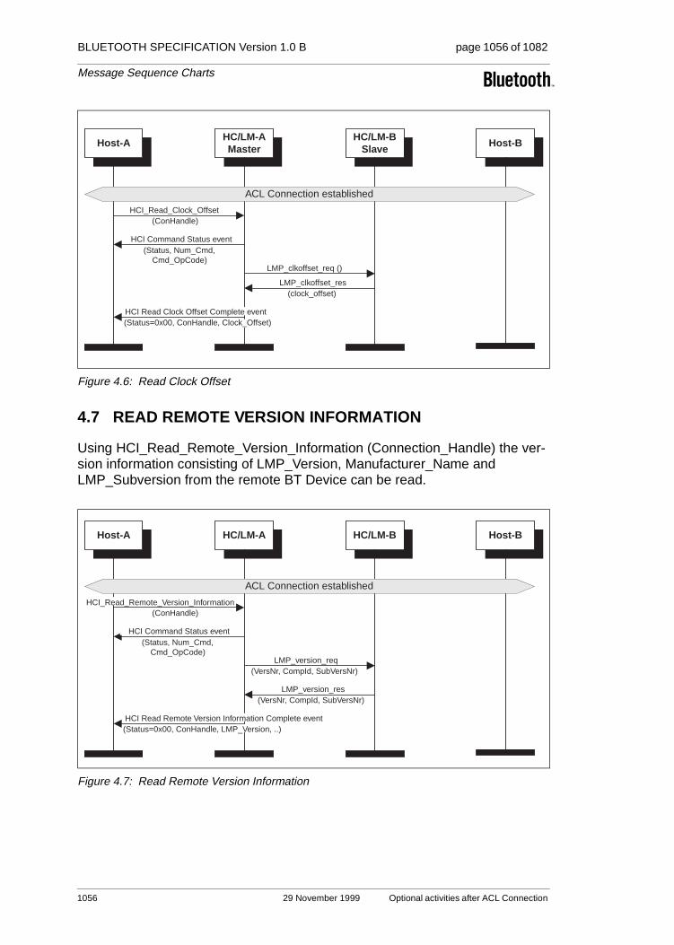
BLUETOOTH SPECIFICATION Version 1.0 B page 1056 of 1082
Message Sequence Charts
Figure 4.6: Read Clock Offset
4.7 READ REMOTE VERSION INFORMATION
Using HCI_Read_Remote_Version_Information (Connection_Handle) the ver-sion information consisting of LMP_Version, Manufacturer_Name and LMP_Subversion from the remote BT Device can be read.
Figure 4.7: Read Remote Version Information
LMP_clkoffset_req ()
(Status, Num_Cmd,Cmd_OpCode)
HCI Command Status event
Host-AHC/LM-AMaster
HC/LM-BSlave
Host-B
(clock_offset)LMP_clkoffset_res
ACL Connection established
(ConHandle)HCI_Read_Clock_Offset
HCI Read Clock Offset Complete event(Status=0x00, ConHandle, Clock_Offset)
(Status, Num_Cmd,Cmd_OpCode)
HCI Command Status event
(ConHandle)
Host-A HC/LM-A HC/LM-B Host-B
(VersNr, CompId, SubVersNr)LMP_version_res
(VersNr, CompId, SubVersNr)LMP_version_req
ACL Connection established
(Status=0x00, ConHandle, LMP_Version, ..)HCI Read Remote Version Information Complete event
HCI_Read_Remote_Version_Information
1056 29 November 1999 Optional activities after ACL Connection

BLUETOOTH SPECIFICATION Version 1.0 B page 1057 of 1082
Message Sequence Charts
4.8 QOS SETUP
To set up the Quality of Service, the command HCI_QoS_Setup (Connection_Handle, Flags, Service_Type, Token_Rate, Peak_Bandwidth, Latency, Delay_Variation) is used.
Figure 4.8: QoS Setup
4.9 SWITCH ROLE
The command HCI_Switch_Role (BD_ADDR, Role) can be used to explicitly switch the current role of the local BT Device for a particular connection with the specified BT Device (BD_ADDR). The local HC/LM has to check whether the switch is performed or not.
(ConHandle, Flags, Service_Type, ..)HCI_QoS_Setup
HCI QoS Setup Complete event(Status=0x00, ConHandle, Flags, ..)
(Status, Num_Cmd,Cmd_OpCode)
HCI Command Status event
HCI QoS Setup Complete event(Status=0x00, ConHandle, Flags, ..)
Host-A HC/LM-A HC/LM-B Host-B
LMP_accepted (opcode)
(poll_interval, N_bc)LMP_quality_of_service_req
ACL Connection established
Optional activities after ACL Connection establishment 29 November 1999 1057

BLUETOOTH SPECIFICATION Version 1.0 B page 1058 of 1082
Message Sequence Charts
Figure 4.9: Switch Role
HCI Role Change eventHCI Role Change event
(Status, Num_Cmd,Cmd_OpCode)
HCI Command Status event
(Status, Num_Cmd,Cmd_OpCode)
HCI Command Status event
Host-A HC/LM-A HC/LM-B Host-B
LMP_accepted (opcode)
LMP_switch_req ()
ACL Connection established
(BD_ADDR, Role=Slave)HCI_Switch_Role
Sub-scenario 1: Master requires theMaster/Slave Switch
/* Master-Role */ /* Slave-Role */
Sub-scenario 2: Slave requires the Master/Slave Switch
/* Master-Role */ /* Slave-Role */
(BD_ADDR, Role=Master)HCI_Switch_Role
LMP_switch_req ()
LMP_accepted (opcode)
Master/Slave Switch(common for sub-scenario 1 and 2)
TDD-Switch ...
(slot_offset, BD_ADDR)LMP_slot_offset
FHS (BD_ADDR, CoD, ..)
"FHS-Ack" (ID-Packet)
Use new channel pameters ...
/* Master-Role *//* Slave-Role */
(slot_offset, BD_ADDR)LMP_slot_offset
(Status=0x00, BD_ADDR, New_Role=Master)(Status=0x00, BD_ADDR, New_Role=Slave)
1058 29 November 1999 Optional activities after ACL Connection

BLUETOOTH SPECIFICATION Version 1.0 B page 1059 of 1082
Message Sequence Charts
5 SCO CONNECTION ESTABLISHMENT AND DETACHMENT
5.1 SCO CONNECTION SETUP
SCO Connection setup requires an established ACL Connection. It is the task of the Host to create an ACL Connection first and then the SCO Link.
Note: On the slave side, an incoming connection request can be automatically accepted by using HCI_Set_Event_Filter (Filter_Type, Filter_Condition_Type, Condition) with the Filter_Type = 0x02 /*Connection_Setup*/. Furthermore, for each SCO Link to a BT Device, a separate SCO Connection Handle is needed.
5.1.1 Master activates the SCO Connection setup
To set up an SCO Connection, the HCI_Add_SCO_Connection (Connection_Handle, Packet_Type) command is used. The specified Connection_Handle is related to the ACL Connection that must have been cre-ated before the HCI_Add_SCO_Connection is issued.
Figure 5.1: SCO Connection setup (activated from master)
HCI Connection Complete event
(Status=0x00, SCO_ConHandle, ..)
HCI Connection Complete event(Status=0x00, SCO_ConHandle, ..)
(Status, Num_Cmd,Cmd_OpCode)
HCI Command Status event
HCI Connection Request event(BD_ADDR, CoD, Link_Type=SCO)
(Status, Num_Cmd,Cmd_OpCode)
HCI Command Status event
(SCO_handle, timing_control_flags, ..)LMP_sco_link_req
Host-AHC/LM-AMaster
HC/LM-BSlave
Host-B
LMP_accepted (opcode)
ACL Connection established
(ACL_ConHandle, Packet_Type)HCI_Add_SCO_Connection
HCI_Accept_Connection_Request(BD_ADDR, Role)
SCO Connection establishment and detachment 29 November 1999 1059

BLUETOOTH SPECIFICATION Version 1.0 B page 1060 of 1082
Message Sequence Charts
5.1.2 Slave activates the SCO Connection setup
The same command HCI_Add_SCO_Connection (Connection_Handle, Packet_Type) can be used to create an SCO Link when the local BT Device is a BT Slave. Here the specified Connection_Handle belongs to the established ACL Connection between the BT Devices. Compared to 5.1.1, the only differ-ence is that the HC/LM Slave starts the SCO Setup with LMP_sco_link_req first.
Figure 5.2: SCO Connection setup (activated from slave)
5.2 SCO DISCONNECTION
An established SCO Connection can be detached at any time. Since several SCO Connections can exist between a BT Master and a BT Slave, an SCO Disconnection only removes the SCO Link with the specified SCO Connection Handle. The other SCO Connections will still exist.
LMP_sco_link_req (..)
HCI_Accept_Connection_Request(BD_ADDR, Role)
HCI Connection Complete event(Status=0x00, SCO_ConHandle, ..)(Status=0x00, SCO_ConHandle, ..)
HCI Connection Complete event
(Status, Num_Cmd,Cmd_OpCode)
HCI Command Status event
HCI Connection Request event(BD_ADDR, CoD,Link_Type=SCO)
(Status, Num_Cmd,Cmd_OpCode)
HCI Command Status event
Host-AHC/LM-AMaster
HC/LM-BSlave
Host-B
LMP_accepted (opcode)
LMP_sco_link_req (..)
ACL Connection established
(ACL_ConHandle', Packet_Type)HCI_Add_SCO_Connection
1060 29 November 1999 SCO Connection establishment and
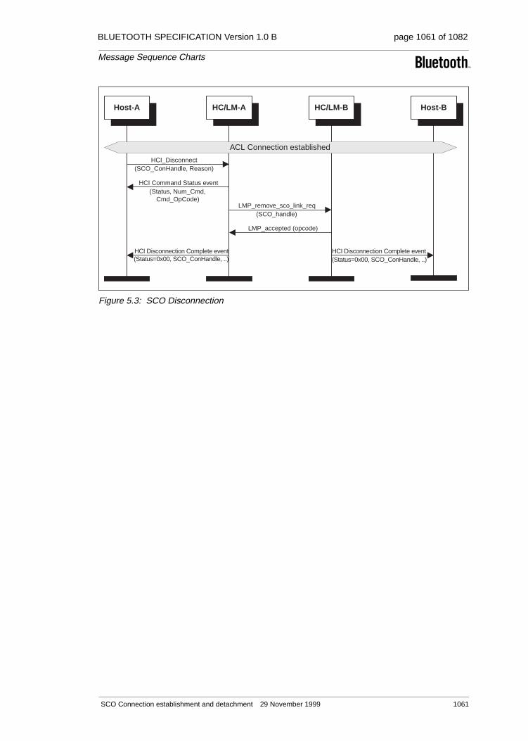
BLUETOOTH SPECIFICATION Version 1.0 B page 1061 of 1082
Message Sequence Charts
Figure 5.3: SCO Disconnection
HCI Disconnection Complete event(Status=0x00, SCO_ConHandle, ..)
HCI Disconnection Complete event(Status=0x00, SCO_ConHandle, ..)
(Status, Num_Cmd,Cmd_OpCode)
HCI Command Status event
Host-A HC/LM-A HC/LM-B Host-B
(SCO_ConHandle, Reason)HCI_Disconnect
ACL Connection established
(SCO_handle)LMP_remove_sco_link_req
LMP_accepted (opcode)
SCO Connection establishment and detachment 29 November 1999 1061
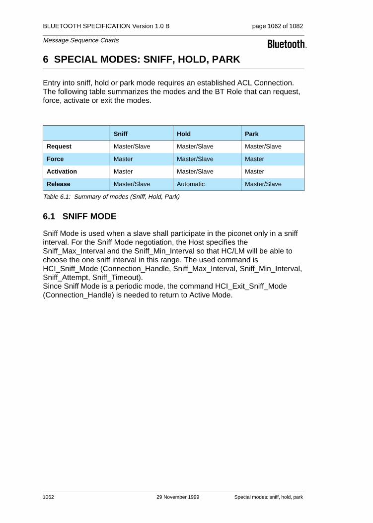
BLUETOOTH SPECIFICATION Version 1.0 B page 1062 of 1082
Message Sequence Charts
6 SPECIAL MODES: SNIFF, HOLD, PARK
Entry into sniff, hold or park mode requires an established ACL Connection. The following table summarizes the modes and the BT Role that can request, force, activate or exit the modes.
6.1 SNIFF MODE
Sniff Mode is used when a slave shall participate in the piconet only in a sniff interval. For the Sniff Mode negotiation, the Host specifies the Sniff_Max_Interval and the Sniff_Min_Interval so that HC/LM will be able to choose the one sniff interval in this range. The used command is HCI_Sniff_Mode (Connection_Handle, Sniff_Max_Interval, Sniff_Min_Interval, Sniff_Attempt, Sniff_Timeout). Since Sniff Mode is a periodic mode, the command HCI_Exit_Sniff_Mode (Connection_Handle) is needed to return to Active Mode.
Sniff Hold Park
Request Master/Slave Master/Slave Master/Slave
Force Master Master/Slave Master
Activation Master Master/Slave Master
Release Master/Slave Automatic Master/Slave
Table 6.1: Summary of modes (Sniff, Hold, Park)
1062 29 November 1999 Special modes: sniff, hold, park

BLUETOOTH SPECIFICATION Version 1.0 B page 1063 of 1082
Message Sequence Charts
Figure 6.1: Sniff Mode
6.2 HOLD MODE
Hold Mode is useful when a BT Device doesn’t want to participate in the connection for a Hold Mode Length. Using the command HCI_Hold_Mode (Connection_Handle, Hold_Max_Length, Hold_Min_Length), the Host speci-fies the Hold_Max_Length and Hold_Min_Length. The HC/LM will then be able to negotiate a Hold Mode Length in this range. When the hold mode is started
HCI Mode Change event
(Status, Num_Cmd,Cmd_OpCode)
HCI Command Status event
(ConHandle, Sniff_Max_Interval, ..)HCI_Sniff_Mode
HCI Mode Change event
HCI Mode Change event
HCI Mode Change event
(Status, Num_Cmd,Cmd_OpCode)
HCI Command Status event
Host-A HC/LM-A HC/LM-B Host-B
ACL Connection established
(timing_control_flags, D_sniff, ..)LMP_sniff
LMP_accepted (opcode)
Sub-scenario 1: Master forces Slave inSniff Mode
Sub-scenario 2: Master or Slaverequests Sniff Mode
(timing_control_flags, D_sniff, ..)LMP_sniff_req
Sub-scenario 3: Exit Sniff Mode
Sniff Mode started
(ConHandle)HCI_Exit_Sniff_Mode
LMP_unsniff_req ()
LMP_accepted (opcode)
/* A=Master */ /* B=Slave */
/* A=Masteror Slave */
/* B=Slaveor Master */
(Status=0x00, ConHandle, Current_Mode=Sniff, ..)
(Status=0x00, ConHandle, Current_Mode=Active, ..)
(Status=0x00, ConHandle, Current_Mode=Active, ..)
(Status=0x00, ConHandle, Current_Mode=Sniff, ..)
Special modes: sniff, hold, park 29 November 1999 1063

BLUETOOTH SPECIFICATION Version 1.0 B page 1064 of 1082
Message Sequence Charts
or complete, Mode Change event (Status, Connection_Handle, Current_Mode, Interval) will be used to inform the Host about the actual mode.
Note: the Hold Mode is exited when the Hold Mode Length has expired, so it is no guarantee that the remote BT Device is immediately active.
Figure 6.2: Hold Mode
LMP_hold (hold_time)
HCI Mode Change event
HCI Mode Change event
HCI Mode Change event
HCI Mode Change event
(Status, Num_Cmd,Cmd_OpCode)
HCI Command Status event
HCI_Hold_Mode
Host-A HC/LM-A HC/LM-B Host-B
ACL Connection established
LMP_hold (hold_time)
LMP_hold (hold_time)
Sub-scenario 1: Master forces Hold Mode
Sub-scenario 2: Slave forces Hold Mode
Hold Mode started
/* A=Master */ /* B=Slave */
/* A=Slave */ /* B=Master */
Hold Mode complete
/* A=Masteror Slave */
/* B=Slave orMaster */
...LMP_hold_req (hold_time)
LMP_accepted (opcode)
Sub-scenario 3: Master or Slave negotiates Hold Mode
(Status=0x00, ConHandle, Current_Mode=Active, ..)
(Status=0x00, ConHandle, Current_Mode=Active, ..)
(Status=0x00, ConHandle, Current_Mode=Hold, ..)
(Status=0x00, ConHandle, Current_Mode=Hold, ..)
(ConHandle, Hold_Mode_Max_Interval, ..)
1064 29 November 1999 Special modes: sniff, hold, park

BLUETOOTH SPECIFICATION Version 1.0 B page 1065 of 1082
Message Sequence Charts
6.3 PARK MODE
Park Mode is used to render the slaves inactive but still synchronized to the master using the beacon interval. In park mode, broadcast is performed.
6.3.1 Enter park mode
Using the command HCI_Park_Mode (Connection_Handle, Beacon_Max_Interval, Beacon_Min_Interval) the Host specifies the Beacon_Max_Interval and Beacon_Min_Interval so that HC/LM can set up a Beacon-Interval in this range for the BT Slaves. In Park Mode, the BT Slave gives up its AM_ADDR.
Special modes: sniff, hold, park 29 November 1999 1065

BLUETOOTH SPECIFICATION Version 1.0 B page 1066 of 1082
Message Sequence Charts
Figure 6.3: Enter Park Mode
6.3.2 Exit Park Mode
Since Park Mode is a periodic mode, the command HCI_Exit_Park_Mode (Connection_Handle) will be used to return to Active Mode. A parked BT Slave can send an Access_Request_Message to request to leave the Park Mode. It is the task of master HC/LM to use LMP_unpark_PM_ADDR_req (..) or LMP_unpark_BD_ADDR_req (..) to unpark a BT Slave.
LMP_park_req ()
LMP_set_broadcast_scan_window(timing_control_flags, D_b, ..)
HCI Mode Change event
HCI Mode Change event
(Status, Num_Cmd,Cmd_OpCode)
HCI Command Status event
HCI_Park_Mode
Host-A HC/LM-A HC/LM-B Host-B
ACL Connection established
(timing_control_flags, D_b, ..)LMP_park
LMP_accepted (opcode)
Sub-scenario 1: Master forces Slave into Park Mode
Park Mode started
/* A=Master */ /* B=Slave */
Sub-scenario 3: Slave requests to be put into Park Mode
Sub-scenario 2: Master requests Slave into Park Mode/* A=Master */ /* B=Slave */
(timing_control_flags, D_b, ..)LMP_park
/* B=Master *//* A=Slave */
LMP_park_req ()
(timing_control_flags, D_b, ..)LMP_park
Optional LM Actions during Park Mode
(timing_control_flags, D_b, ..)LMP_modify_beacon
/* A=Master */ /* B=Slave */
(Status=0x00, ConHandle, Current_Mode=Park, ..)
(Status=0x00, ConHandle, Current_Mode=Park, ..)
(ConHandle, Beacon_Max_Interval, ..)
1066 29 November 1999 Special modes: sniff, hold, park

BLUETOOTH SPECIFICATION Version 1.0 B page 1067 of 1082
Message Sequence Charts
Figure 6.4: Exit Park Mode
HCI Mode Change event
HCI Mode Change event
(timing_control_flags, D_b, ..)
/* to all slaves */LMP_unpark_PM_ADDR_req
/* to all slaves */LMP_unpark_BD_ADDR_req
(Status, Num_Cmd,Cmd_OpCode)
HCI Command Status event
Host-A HC/LM-A HC/LM-B Host-B
(ConHandle)HCI_Exit_Park_Mode
ACL Connection established
LMP_accepted (opcode)
Sub-scenario 1: Master unparks Slaveusing BD_ADDR
/* A=Master */ /* B=Slave */
Sub-scenario 3: Slave unparks itself
Sub-scenario 2: Master unparks Slaveusing PM_ADDR
/* A=Master */ /* B=Slave */
/* B=Master *//* A=Slave */
LMP_accepted (opcode)/* only from this slave */
/* only from this slave */
LMP_accepted (opcode)
(Status=0x00, ConHandle, Current_Mode=Active, ..)
(Status=0x00, ConHandle, Current_Mode=Active, ..)
"Access_Request_Message" (ID-Packet)
(timing_control_flags, D_b, BD_ADDR, ..)
(timing_control_flags, D_b, BD_ADDR, ..)
LMP_unpark_BD_ADDR/PM_ADDR_req
Special modes: sniff, hold, park 29 November 1999 1067
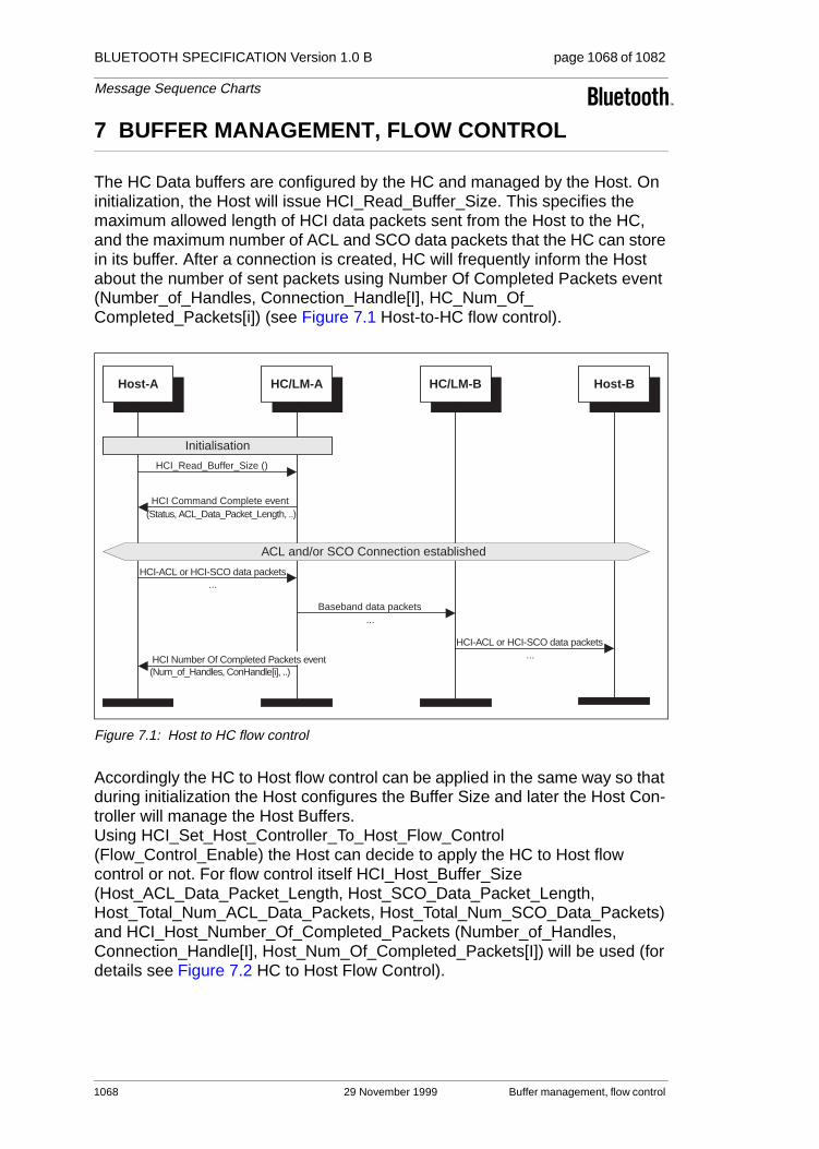
BLUETOOTH SPECIFICATION Version 1.0 B page 1068 of 1082
Message Sequence Charts
7 BUFFER MANAGEMENT, FLOW CONTROL
The HC Data buffers are configured by the HC and managed by the Host. On initialization, the Host will issue HCI_Read_Buffer_Size. This specifies the maximum allowed length of HCI data packets sent from the Host to the HC, and the maximum number of ACL and SCO data packets that the HC can store in its buffer. After a connection is created, HC will frequently inform the Host about the number of sent packets using Number Of Completed Packets event (Number_of_Handles, Connection_Handle[I], HC_Num_Of_Completed_Packets[i]) (see Figure 7.1 Host-to-HC flow control).
Figure 7.1: Host to HC flow control
Accordingly the HC to Host flow control can be applied in the same way so that during initialization the Host configures the Buffer Size and later the Host Con-troller will manage the Host Buffers. Using HCI_Set_Host_Controller_To_Host_Flow_Control (Flow_Control_Enable) the Host can decide to apply the HC to Host flow control or not. For flow control itself HCI_Host_Buffer_Size (Host_ACL_Data_Packet_Length, Host_SCO_Data_Packet_Length, Host_Total_Num_ACL_Data_Packets, Host_Total_Num_SCO_Data_Packets) and HCI_Host_Number_Of_Completed_Packets (Number_of_Handles, Connection_Handle[I], Host_Num_Of_Completed_Packets[I]) will be used (for details see Figure 7.2 HC to Host Flow Control).
HCI-ACL or HCI-SCO data packets...
(Num_of_Handles, ConHandle[i], ..)
HCI-ACL or HCI-SCO data packets...
HCI Command Complete event(Status, ACL_Data_Packet_Length, ..)
Host-A HC/LM-A HC/LM-B Host-B
...Baseband data packets
ACL and/or SCO Connection established
HCI_Read_Buffer_Size ()
Initialisation
HCI Number Of Completed Packets event
1068 29 November 1999 Buffer management, flow control

BLUETOOTH SPECIFICATION Version 1.0 B page 1069 of 1082
Message Sequence Charts
Figure 7.2: HC to Host Flow Control
(Num_of_Handles, ConHandle[i], ..)
HCI-ACL or HCI-SCO data packets...
HCI-ACL or HCI-SCO data packets...
(Host_ACL_Data_Packet_Length, ..)HCI_Host_Buffer_Size
(Flow_Control_Enable=ON)
HCI Command Complete event(Num_Cmd, Cmd_OpCode,
Status)
HCI Command Complete event(Num_Cmd, Cmd_OpCode, Status)
Host-A HC/LM-A HC/LM-B Host-B
...Baseband data packets
ACL and/or SCO Connection established
Initialisation
HCI_Host_Number_Of_Completed_Packets
HCI_Set_Host_Controller_To_Host_Flow_Control
Buffer management, flow control 29 November 1999 1069

BLUETOOTH SPECIFICATION Version 1.0 B page 1070 of 1082
Message Sequence Charts
8 LOOPBACK MODE
8.1 LOCAL LOOPBACK MODE
The local Loopback Mode is used to loopback received HCI Commands, and HCI ACL and HCI SCO packets sent from the Host.
The HC will send four Connection Complete events (one for ACL, three for SCO Connections) so that the Host can use the Connection_Handles to re-send HCI ACL and HCI SCO Packet to HC. To exit the local Loopback Mode, HCI_Write_Loopback_Mode (Loopback_Mode=0x00) or HCI_Reset ( ) will be used.
1070 29 November 1999 Loopback Mode

BLUETOOTH SPECIFICATION Version 1.0 B page 1071 of 1082
Message Sequence Charts
Figure 8.1: Local Loopback Mode
(Status, SCO_ConHandle3, BD_ADDR, Link_Type=SCO, Encr_Mode)HCI Connection Complete event
(Status, SCO_ConHandle2, BD_ADDR, Link_Type=SCO, Encr_Mode)HCI Connection Complete event
(Status, SCO_ConHandle1, BD_ADDR, Link_Type=SCO, Encr_Mode)HCI Connection Complete event
(Status, ACL_ConHandle, BD_ADDR, Link_Type=ACL, Encr_Mode)HCI Connection Complete event
Host HC/LM
Enter Local Loopback Mode
(Loopback_Mode=local loopback)HCI_Write_Loopback_Mode
Sub-scenario 1: loopback HCI-ACL and HCI-SCO packets
HCI-ACL, HCI-SCO packets ..
HCI-ACL, HCI-SCO packets ..
/* loopback all receivedHCI-ACL and HCI-SCO
packets */
Sub-scenario 2: loopback HCI Command packets
HCI-Command packets ..
(HCI_Command_Packet)HCI Loopback Command event
/* Special commands likeHCI_Buffer_Size .. will not
be looped back */
Exit Local Loopback Mode
(Loopback_Mode=no loopback)HCI_Write_Loopback_Mode
(Status=0x00, SCO_ConHandle1, Reason)HCI Disconnection Complete event
(Status=0x00, SCO_ConHandle2, Reason)HCI Disconnection Complete event
(Status=0x00, SCO_ConHandle3, Reason)HCI Disconnection Complete event
(Status=0x00, ACL_ConHandle, Reason)HCI Disconnection Complete event
(Num_Cmd, Cmd_OpCode=HCI_Write_Loopback_Mode, Status)HCI Command Complete event
(Num_Cmd, Cmd_OpCode=HCI_Write_Loopback, Status)HCI Command Complete event
Loopback Mode 29 November 1999 1071

BLUETOOTH SPECIFICATION Version 1.0 B page 1072 of 1082
Message Sequence Charts
8.2 REMOTE LOOPBACK MODE
The remote Loopback Mode is used to loopback all received Baseband ACL and SCO Data received from a remote BT Device. During remote Loopback Mode, ACL and SCO Connection can be created. The remote Loopback Mode can be released with the command HCI_Write_Loopback_Mode (Loopback_Mode=0x00).
Figure 8.2: Remote Loopback Mode
HCI Command Complete event(Num_Cmd, Cmd_OpCode,
Status)
HCI Command Complete event(Num_Cmd, Cmd_OpCode,
Status)
(Loopback_Mode=remote loopback)HCI_Write_Loopback_Mode
Host-A HC/LM-A HC/LM-B Host-B
HCI-ACL, HCI-SCO packets ..
Baseband ACL-, SCO-Packets ..
Enter Remote Loopback Mode
Create ACL Connection
Create SCO Connections
HCI-ACL, HCI-SCO packets ..
Baseband ACL-, SCO-Packets ..
Exit Remote Loopback Mode
Remove ACL Connection
Remove SCO Connections
(Loopback_Mode=no loopback)HCI_Write_Loopback_Mode
1072 29 November 1999 Loopback Mode

BLUETOOTH SPECIFICATION Version 1.0 B page 1073 of 1082
Message Sequence Charts
9 LIST OF ACRONYMS AND ABBREVIATIONS
BT Bluetooth
HC Host Controller
HCI Host Controller Interface
LAP Lower Address Part
LC Link Controller
LM Link Manager
LMP Link Manager Protocol
MSC Message Sequence Chart
PDU Protocol Data Unit
List of Acronyms and Abbreviations 29 November 1999 1073

BLUETOOTH SPECIFICATION Version 1.0 B page 1074 of 1082
Message Sequence Charts
10 LIST OF FIGURES
Figure 2.1: Remote Name Request .........................................................1039Figure 2.2: One-Time Inquiry ...................................................................1040Figure 2.3: Periodic Inquiry ......................................................................1041Figure 3.1: Overview of ACL Connection establishment
and detachment .....................................................................1042Figure 3.2: ACL Connection Request phase ...........................................1044Figure 3.3: ACL Connection setup with pairing........................................1046Figure 3.4: ACL Connection setup with authentication ............................1047Figure 3.5: Encryption and Setup complete.............................................1048Figure 3.6: ACL Disconnection ................................................................1049Figure 4.1: Authentication Requested......................................................1050Figure 4.2: Set Connection Encryption ....................................................1052Figure 4.3: Change Connection Link Key ................................................1053Figure 4.4: Master Link Key .....................................................................1054Figure 4.5: Read Remote Supported Features........................................1055Figure 4.6: Read Clock Offset..................................................................1056Figure 4.7: Read Remote Version Information.........................................1056Figure 4.8: QoS Setup .............................................................................1057Figure 4.9: Switch Role............................................................................1058Figure 5.1: SCO Connection setup (activated from master) ....................1059Figure 5.2: SCO Connection setup (activated from slave).......................1060Figure 5.3: SCO Disconnection ...............................................................1061Figure 6.1: Sniff Mode..............................................................................1063Figure 6.2: Hold Mode .............................................................................1064Figure 6.3: Enter Park Mode....................................................................1066Figure 6.4: Exit Park Mode ......................................................................1067Figure 7.1: Host to HC flow control ..........................................................1068Figure 7.2: HC to Host Flow Control ........................................................1069Figure 8.1: Local Loopback Mode............................................................1071Figure 8.2: Remote Loopback Mode........................................................1072
1074 29 November 1999 List of Figures

BLUETOOTH SPECIFICATION Version 1.0 B page 1075 of 1082
Message Sequence Charts
11 LIST OF TABLES
Table 6.1: Summary of modes (Sniff, Hold, Park)...................................1062
List of Tables 29 November 1999 1075

BLUETOOTH SPECIFICATION Version 1.0 B page 1076 of 1082
Message Sequence Charts
12 REFERENCES
[1] “Baseband Specification” on page 33
[2] “Link Manager Protocol” on page 185
[3] “Host Controller Interface Functional Specification” on page 517
[4] “Logical Link Control and Adaptation Protocol Specification” on page 245
1076 29 November 1999 References

BLUETOOTH SPECIFICATION Version 1.0 B page 1077 of 1082
Alphabetical Index
Numerics0x7E [H:3] 784
AAbort- [F:2] 420
ACCESS RIGHTS ACCEPT [F:3] 451
ACCESS RIGHTS REJECT [F:3] 451
ACCESS RIGHTS REQUEST [F:3] 451
Ack Code [H:3] 781
Ack code [H:3] 780
Acknowledgement Timer (T1) [F:1] 400
ALERTING [F:3] 442
asynchronous notifications [F:4] 508
AT+CMUX [F:1] 399
authentication [C] 194
Bbasic option [F:1] 396, [F:1] 398
Baud Rate [H:3] 781
baud rate [F:1] 391, [H:3] 780
beacon [C] 211
beginning delimiter [H:3] 785
Bluetooth [F:2] 414
BOF(0x7E) [H:3] 786
Briefcase Trick [F:4] 500
business card [F:2] 415
byte ordering [F:1] 390
byte stream [F:2] 421
CCall Control [F:3] 435
CALL PROCEEDING [F:3] 441
Calling Line Identity [F:3] 456
checksum [H:3] 785
CL INFO [F:3] 455
claimant [C] 194
clock offset [C] 202
COBS [H:3] 784, [H:3] 785, [H:3] 787
COBS code block [H:3] 787
COBS code byte [H:3] 787
combination key [C] 197
commands in TS 07.10 [F:1] 396
Configuration distribution [F:3] 449
CONNECT [F:3] 442
Connect-request [F:2] 418
Consistent Overhead Byte Stuffing [H:3] 785
control channel [F:1] 396
convergence layer [F:1] 397
CRC [H:3] 782
CRC-CCITT [H:3] 785, [H:3] 786
CTS [H:3] 788
current link key [C] 198
DData Link Connection Identifier [F:1] 393
data throughput [F:1] 391
DCE [F:1] 391
default URL [F:4] 509
delayed loopback [I:1] 812
Delimiter [H:3] 782
delimiter 0x7E [H:3] 785
delimiter, 0x7E [H:3] 784
direction bit [F:1] 400
DISC command [F:1] 400, [F:1] 401
DISC command frame [F:1] 399
DISCONNECT [F:3] 446
Disconnect-request [F:2] 419
DNS [F:4] 503
drift [C] 203
DTE [F:1] 391, [F:1] 399
DTMF ACKNOWLEDGE [F:3] 457
DTMF start & stop [F:3] 456
DTR/DSR [F:1] 403
EEIATIA-232-E [F:1] 389, [F:1] 391
eliminating zeros [H:3] 785
emergency call [F:3] 479
emulated ports [F:1] 393
encryption [C] 199
ending delimiter [H:3] 785
EOF(0x7E) [H:3] 786
Error detection [H:3] 780
error message packet [H:3] 785, [H:3] 789
Error Message Packet (0x05) [H:3] 779
error packet [H:3] 788
Error Recovery [H:3] 783
error recovery [H:3] 780, [H:3] 784
error recovery procedure [H:3] 785, [H:3] 788
Error Type [H:3] 786, [H:3] 789
ETSI TS 07.10 [F:2] 421
external call [F:3] 479
29 November 1999 1077
BLUETOOTH SPECIFICATION Version 1.0 B page 1078 of 1082
Confidential Bluetooth
FFast inter member access [F:3] 449
FCoff [F:1] 403
FCon [F:1] 403
flow control [F:1] 403
Forbidden Message [F:4] 501
frame types [F:1] 396
Ggenerator polynomial [H:3] 785
Get-request [F:2] 420
Group Management [F:3] 435
HHCI RS232 Transport Layer [H:3] 778
header ID [F:2] 417
hold mode [C] 208
Host Controller Interface [F:4] 508
HTML [F:4] 505
HTTP [F:4] 503, [F:4] 505
Iin-band tones/announcements [F:3] 443
INFO ACCEPT [F:3] 452
INFO SUGGEST [F:3] 452
INFORMATION [F:3] 441
initialisation key [C] 195
intercom call [F:3] 479
Internet Engineering Task Force (IETF) [F:4] 504
interoperability [F:4] 511
interrupt latency [H:3] 780
IrCOMM [F:2] 416
IrDA [F:2] 414
IrMC [F:2] 425
IrOBEX [F:2] 414
JJavaScript [F:4] 505
jitter [C] 203
LL2CAP channel [F:1] 407
latency requirements [F:1] 407
link key [C] 194
link loss notification [F:1] 399, [F:1] 407
link supervision [C] 224
LISTEN REJECT [F:3] 454
LISTEN REQUEST [F:3] 453
LISTEN SUGGEST [F:3] 453
loop back test [I:1] 815
low power mode [F:1] 407
MManagement Entity [F:4] 508
Maximum Frame Size (N1) [F:1] 400
Modem Status Command [F:1] 397
multiple bearers [F:4] 508
multiplexer control channel [F:1] 399
Multiplexer Control commands [F:1] 401
Nname request [C] 207
negotiation packet [H:3] 780, [H:3] 781
Negotiation Packet (0x06) [H:3] 779
negotiation phase [H:3] 780
null modem [F:1] 392
null modem emulation [F:1] 391
number of data bit [H:3] 780
number of stop bit [H:3] 780
OOBEX [F:2] 414
OBEX session protocol [F:2] 417
Obtain access rights [F:3] 449
output power [C] 215
Ppaging scheme [C] 223
pairing [C] 195
parity type [H:3] 780
park mode [C] 211
payload heade [C] 192
PIN [C] 195
PN command [F:1] 402
port emulation entity [F:1] 405
port proxy entity [F:1] 405
Protocol Mode [H:3] 782
protocol mode [H:3] 780
protocol mode 0x13 [H:3] 785
protocol mode 0x14 [H:3] 788
Proxy/gateway Addressing [F:4] 509
Put-request [F:2] 419
QQ.931 [F:3] 435
Quality of Service [C] 218
Rregister recall [F:3] 456
1078 29 November 1999

BLUETOOTH SPECIFICATION Version 1.0 B page 1079 of 1082
RELEASE [F:3] 446
RELEASE COMPLETE [F:3] 446
reliability [F:1] 407
reliable transmission [F:1] 400
Response Timer for Multiplexer Control Chan-nel (T2) [F:1] 400
resynchronization [H:3] 784
resynchronize [H:3] 788
retransmission holding buffer [H:3] 785, [H:3] 788
retransmission packets [H:3] 785, [H:3] 788
RFCOMM [F:2] 414
RFCOMM entity [F:1] 393
RFCOMM multiplexer [F:1] 399
RFCOMM reference model [F:1] 395
RFCOMM Server Channel [F:1] 405
RFCOMM server channels [F:1] 393, [F:1] 400
RFCOMM session [F:1] 393, [F:1] 399
RLS command [F:1] 402
RPN command [F:1] 401
RS-232 [F:1] 389, [F:1] 391, [F:1] 405
RS232 [H:3] 778
RS-232 control signals [F:1] 392, [F:1] 397
RS232 Transport Packet [H:3] 779
RSSI [C] 215
RTS [H:3] 788
RTS/CTS [F:1] 403, [H:3] 780
RTS/CTS Mode [H:3] 782
SSABM command [F:1] 399, [F:1] 400
SCO link [C] 219
semi-permanent link key [C] 198, [C] 199
SEQ No with Error [H:3] 785
sequence number [H:3] 779
sequence number field [H:3] 785, [H:3] 788
Sequence Number with Error field [H:3] 785, [H:3] 788
serial port emulation entity [F:1] 395
service call [F:3] 479
Service Discovery Protocol [F:4] 506, [F:4] 512
service records [F:1] 405
SetPath- [F:2] 420
SETUP [F:3] 439
SETUP ACKNOWLEDGE [F:3] 441
simple error recovery scheme [H:3] 788
Smart Kiosk [F:4] 501
sniff mode [C] 209
SSL [F:4] 505
START DTMF [F:3] 457
START DTMF REJECT [F:3] 457
STOP DTMF [F:3] 457
STOP DTMF ACKNOWLEDGE [F:3] 457
supervision timeout [C] 224
synchronization [H:3] 785
synchronize [H:3] 788
TTCP [F:4] 505
TCP port number [F:2] 423
TCP/IP [F:2] 414
TCS Binary [F:3] 435
Tdetect [H:3] 780
Tdetect Time [H:3] 782
Tdetect time [H:3] 788
temporary link key [C] 198
test mode [C] 237, [I:1] 806
Tiny TP [F:2] 416
transmitter test [I:1] 811
TS 07.10 [F:1] 389
TS 07.10 multiplexer [F:1] 393, [F:1] 407
UUART [H:3] 780
UART Settings [H:3] 781
UDP [F:4] 504
Uniform Resource Locators [F:4] 509
unit key [C] 197
URL [F:4] 507
User Addressing [F:4] 509
VvCalendar [F:2] 415
vCard [F:2] 415
verifier [C] 194
vMessage [F:2] 415
vNotes [F:2] 415
WWAP Client [F:4] 502
WAP Proxy/gateway [F:4] 503
WAP Server [F:4] 503
WDP [F:4] 504
Wireless User Group [F:3] 449
WSP [F:4] 504
WTLS [F:4] 504
WTP [F:4] 504
WUG [F:3] 449
29 November 1999 1079

BLUETOOTH SPECIFICATION Version 1.0 B page 1080 of 1082
Confidential Bluetooth
XXML [F:4] 505
XON/XOFF [F:1] 403
Zzero elimination [H:3] 787
1080 29 November 1999


1082