bn 10.030 broetje-automation company standard … · broetje-automation company standard ba catia...
TRANSCRIPT

BN 10.030 Index 10
Broetje-Automation Company Standard BA CATIA Guideline
1 Scope and Objective .................................................................................. 3
1.1 Contact persons 3
1.2 List of abbreviations: 4
1.3 CATIA V5 4
2 Naming Conventions ................................................................................. 5
2.1 Explanation 5
2.2 Generating V5 Data 6
3 Product Structure ...................................................................................... 7
3.1 Product design 8
3.2 Constraints (Assembly Constraints) 9
3.3 Assembly features 9
3.4 Color assignments in products: 10
4 Skeleton Structure ................................................................................... 11
4.1 General 11
4.2 Product structure based on skeleton 12
4.3 Transfer of information based on skeleton 13
4.4 Skeleton part structure 14
5 Part Structure ........................................................................................... 15
5.1 Naming of axis systems and bodies 15
5.2 Color assignment axes systems 15
5.3 Publications 16
5.4 Sketcher 16
5.5 Color assignment in part design 17
5.6 Body 17
5.7 Boolesche operations 18
5.8 Material 18
5.9 General information regarding the design of production parts in PartDesign 18
6 Mirroring ................................................................................................... 19
7 Handling constraining contours/measuring plans (ASM-assemblies) 20
8 Welded Designs ....................................................................................... 21
9 Generation of Drawings .......................................................................... 22
10........................................................................................................................ BA Catalogs 23
10.1 Standard catalog 23
10.2 Material catalog 24
11............................................. Handling Standard and Purchase Parts (internal) 24
11.1 Standard parts 24
11.2 Purchase parts 25
12................................................................................................................... Quality of Data 25
13................................................................................................................ External Offices 26
Change History:
10 Change Broetje Logo Baumann 09.08.2012
09 2.1, 2.2 amended, 9.6, 9.10 removed MH 25 Nov. 2011
08 5.3 / 5.5 / 5.9 / 7 supplemented/redacted 9.11 deleted
MH / SK 28 Sep. 2011
07 4.4 / 5.1 / 5.3 / 7 / 9.15 / 11 / 13 amended/added SK / MH 16 Feb. 2011
06 overall revision SK / MH 01 Oct. 2010
05 overall revision MH / Nol 10 Feb. 2010
04 overall revision/redaction MH / Nol 07 Dec. 2009
03 3.2 / 4.2 / 6.1 - amended Nol 24 Nov. 2009
02 2.1 / 3.12 - amended Nol 19 Oct. 2009
01 Creation in document management system Nol 14 Apr. 2009
Index Designation Name Date Released:
Page 2 of 26 25 Nov. 2011

BN 10.030 Index 10
Broetje-Automation Company Standard BA CATIA Guideline
Page 3 of 26
25 Nov. 2011
1 Scope and Objective This guideline provides a description of the structured methods for generating CAD data using CATIA V5. It is a binding procedure within the scope of
DIN EN 9100 Certification for all employees of the design department of BA and BAJ, as well as for contractors, who are undertaking any design assignments for these companies. Further to this guideline, please refer to the "BN10.010 Design Guideline" found in the document management for information on the general procedure related to design and technical drawings. Any deviations from this guideline must be cleared with the project manager and the CAD department and are to be documented. This applies in particular for any projects that are subject to external guidelines.
1.1 Contact information
Telephone: +49(0)4402-966460 Mail: [email protected]
BN 10.030 Index 10
Broetje-Automation Company Standard BA CATIA Guideline
Page 4 of 26
25 Nov. 2011
1.2 List of abbreviations: BA Broetje-Automation GmbH BAW Broetje-Automation, Wiefelstede BAJ Broetje-Automation, Jaderberg (previously HC / Hydro Control) AMS Order-Management-System (internal BA ERP System) EDM Engineering Data Management CDB EDM System CIM DATABASE WSM WorkspaceManager (integral part of the EDM System) Env Environment (Component) HF Hot Fix SP Service Pack Skt Skeleton (Part) Asm Assembly SWT Welded part [Schweißteil] DMU Digital MockUp (space-saving illustration) B-Rep B-Rep feature are features not included in the structure tree. (e.g. edges of bodies, partial areas of solids, etc.) GSMD Generative SheetMetalDesign (Catia Workbench)
1.3 CATIA V5
The Broetje V5 environment is to be used for all orders unless specified otherwise (project-specific requirements, e.g. AIRBUS-environment). The English user interface must be used exclusively. The current installation package is available on the Broetje-Automation FTP server. Access data will be provided upon request. The required configuration can be found in the company standard entitled "Hardware and Software Requirements" or may be requested from the CAD department. Refer to chapter 1.1 for competent contact persons
BN 10.030 Index 10
Broetje-Automation Company Standard BA CATIA Guideline
Page 5 of 26
25 Nov. 2011
2 Naming Conventions
2.1 Explanation
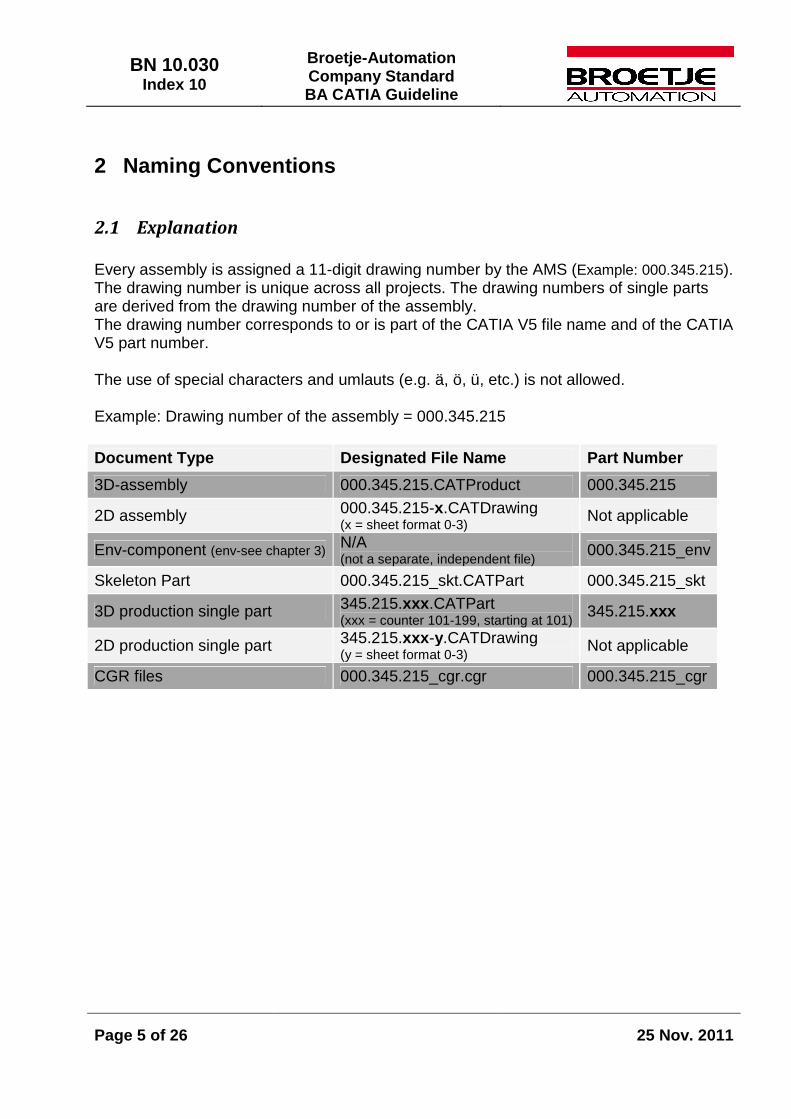
Every assembly is assigned a 11-digit drawing number by the AMS (Example: 000.345.215). The drawing number is unique across all projects. The drawing numbers of single parts are derived from the drawing number of the assembly. The drawing number corresponds to or is part of the CATIA V5 file name and of the CATIA V5 part number. The use of special characters and umlauts (e.g. ä, ö, ü, etc.) is not allowed. Example: Drawing number of the assembly = 000.345.215
Document Type Designated File Name Part Number
3D-assembly 000.345.215.CATProduct 000.345.215
2D assembly 000.345.215-x.CATDrawing (x = sheet format 0-3) Not applicable
Env-component (env-see chapter 3) N/A (not a separate, independent file) 000.345.215_env
Skeleton Part 000.345.215_skt.CATPart 000.345.215_skt
3D production single part 345.215.xxx.CATPart (xxx = counter 101-199, starting at 101) 345.215.xxx
2D production single part 345.215.xxx-y.CATDrawing (y = sheet format 0-3)
Not applicable
CGR files 000.345.215_cgr.cgr 000.345.215_cgr

BN 10.030 Index 10
Broetje-Automation Company Standard BA CATIA Guideline
Page 6 of 26
25 Nov. 2011
2.2 Generating V5 Data
2.2.1 Product and part properties The specified naming conventions must be observed when creating a product, part or drawing. The BA Standard Tool is to be used for that purpose. 2.2.2 Automating the generation of data using the standard tool
The macro is called up via the icon.
(Fig. revised Nov.2011)
The standard tool offers various descriptions/explanations which can be called up by
clicking on the corresponding icons ( , ).

BN 10.030 Index 10
Broetje-Automation Company Standard BA CATIA Guideline
Page 7 of 26
25 Nov. 2011
3 Product Structure The product structure for a project is specified by BA.
Components may be used when creating production assemblies to improve structure and handling. It is imperative to adhere to the assembly structure specified in the AMS. Inserted components must not conflict with the kinematic aspects of the assembly, i.e. it must be and remain possible to simulate the model. Combining parts of a screwed connection (screw, washer and nut) to one component is sensible and effective. The screwed connection component may then be used in several positions within the same assembly. AMS drawing numbers may not be used to name components!
BN 10.030 Index 10
Broetje-Automation Company Standard BA CATIA Guideline
Page 8 of 26
25 Nov. 2011
3.1 Product design
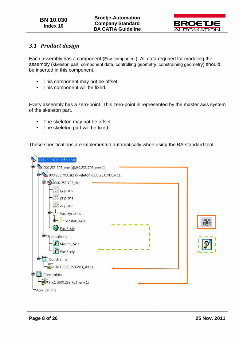
Each assembly has a component (Env-component). All data required for modeling the assembly (skeleton part, component data, controlling geometry, constraining geometry) should be inserted in this component.
• This component may not be offset • This component will be fixed.
Every assembly has a zero-point. This zero-point is represented by the master axis system of the skeleton part.
• The skeleton may not be offset • The skeleton part will be fixed.
These specifications are implemented automatically when using the BA standard tool.
BN 10.030 Index 10
Broetje-Automation Company Standard BA CATIA Guideline
Page 9 of 26
25 Nov. 2011
3.2 Constraints (Assembly Constraints)
Allowed constraints include:
• Coincidence • Contact • Offset • Angle
Exceptions: The use of the constraint Fix is allowed to fix components, skeletons and parts (customer data). Constraints should only be created between features that have already been published. When features are to be published, those that can be selected from the structure tree (point, line, plane, body, etc.) should be preferred to partial surfaces, etc.
All parts of the assembly must only have the degree of freedom that is required for their movement/function. Example: a screw may indeed rotate around its own axis. Production parts may not be positioned over standard and purchase parts. This facilitates the replacement of standard and purchase parts at a later time. Example: Screwed connections with two metal sheets. First, link the metal sheets to be screwed together with constraints, then link the screw with the outer sheet.
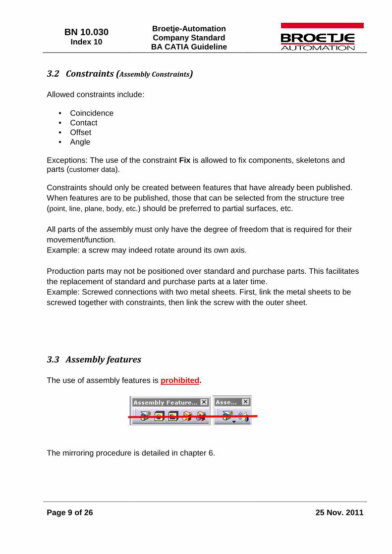
3.3 Assembly features
The use of assembly features is prohibited. The mirroring procedure is detailed in chapter 6.
BN 10.030 Index 10
Broetje-Automation Company Standard BA CATIA Guideline
Page 10 of 26
25 Nov. 2011
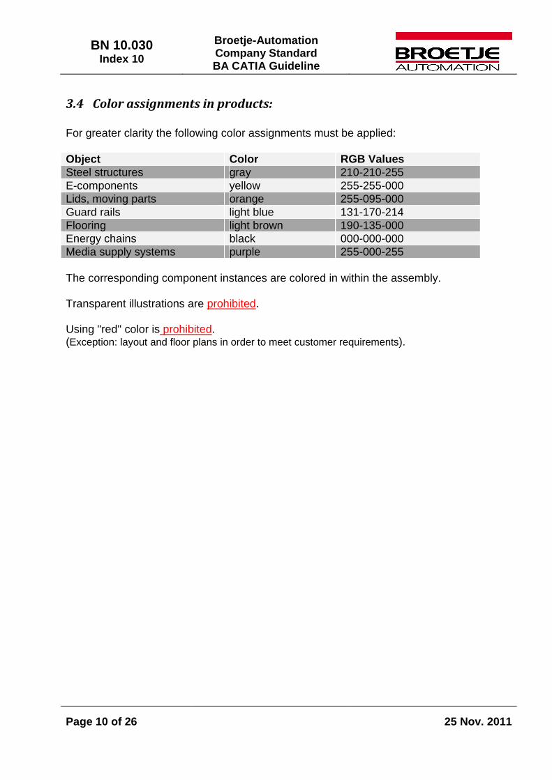
3.4 Color assignments in products:
For greater clarity the following color assignments must be applied: Object Color RGB Values Steel structures gray 210-210-255 E-components yellow 255-255-000 Lids, moving parts orange 255-095-000 Guard rails light blue 131-170-214 Flooring light brown 190-135-000 Energy chains black 000-000-000 Media supply systems purple 255-000-255 The corresponding component instances are colored in within the assembly. Transparent illustrations are prohibited. Using "red" color is prohibited. (Exception: layout and floor plans in order to meet customer requirements).
BN 10.030 Index 10
Broetje-Automation Company Standard BA CATIA Guideline
Page 11 of 26
25 Nov. 2011
4 Skeleton Structure
The skeleton structure in the product design must be uniform.
4.1 General
All component data as well as environmental geometries (production facility, adjacent machines, traffic routes, etc.) must be stored with the main assembly environment. All geometries needed are transferred to the sub-assemblies by publication.
The volume of information to be transferred should be as comprehensive as needed and as limited as possible!
BN 10.030 Index 10
Broetje-Automation Company Standard BA CATIA Guideline
Page 12 of 26
25 Nov. 2011
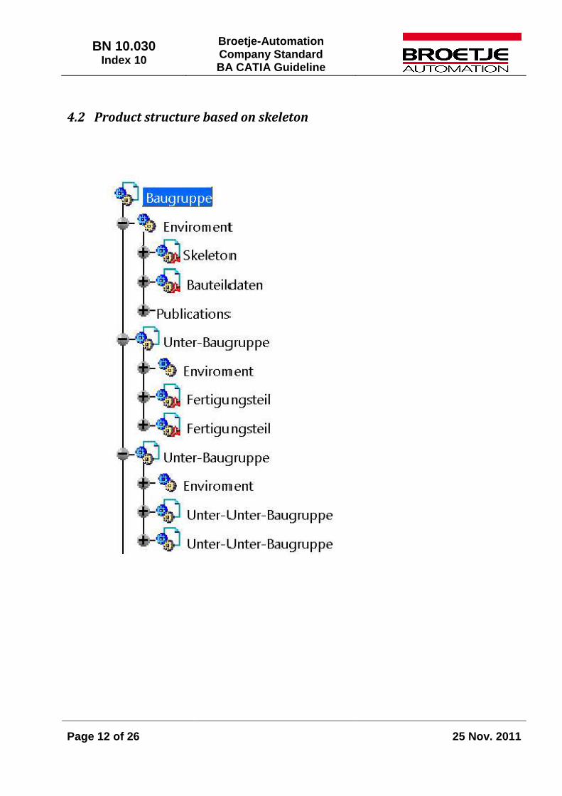
4.2 Product structure based on skeleton

BN 10.030 Index 10
Broetje-Automation Company Standard BA CATIA Guideline
Page 13 of 26
25 Nov. 2011
4.3 Transfer of information based on skeleton
BN 10.030 Index 10
Broetje-Automation Company Standard BA CATIA Guideline
Page 14 of 26
25 Nov. 2011
4.4 Skeleton part structure
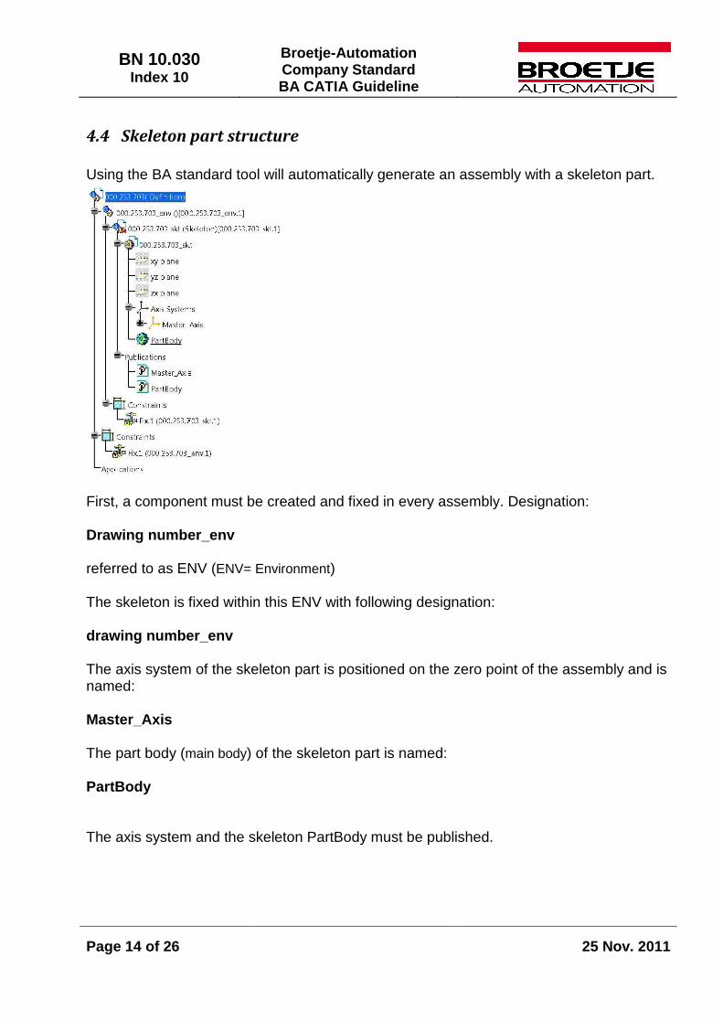
Using the BA standard tool will automatically generate an assembly with a skeleton part.
First, a component must be created and fixed in every assembly. Designation: Drawing number_env referred to as ENV (ENV= Environment) The skeleton is fixed within this ENV with following designation: drawing number_env The axis system of the skeleton part is positioned on the zero point of the assembly and is named: Master_Axis The part body (main body) of the skeleton part is named: PartBody The axis system and the skeleton PartBody must be published.
BN 10.030 Index 10
Broetje-Automation Company Standard BA CATIA Guideline
Page 15 of 26
25 Nov. 2011
5 Part Structure Hybrid-Bodies are prohibited.
5.1 Naming of axis systems and bodies
The main body is named PartBody. The axis system is named:
Model Type Name of Axis System
Single Part Axis SWT raw part Axis Standard part Axis purchased part Axis Skeleton Master_Axis
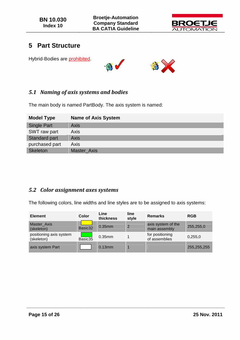
5.2 Color assignment axes systems
The following colors, line widths and line styles are to be assigned to axis systems:
Element Color Line thickness
line style Remarks RGB
Master_Axis (skeleton)
Basic32 0.35mm 2 axis system of the
main assembly 255,255,0
positioning axis system (skeleton)
Basic35
0.35mm 1 for positioning of assemblies
0,255,0
axis system Part 0.13mm 1 255,255,255

BN 10.030 Index 10
Broetje-Automation Company Standard BA CATIA Guideline
Page 16 of 26
25 Nov. 2011
5.3 Publications
When features are published, their name must be preceded by the following abbreviations: PartBody Axis Axis Axis (skeleton) Master_Axis Surface su_ Plane pl_ Point pt_ Line ln_ Sketch sk_ Parameter pa_ Curve (spline) cu_ Features from the structure tree are to be preferred for publications. The use of B-Rep features such as partial surfaces of edges of bodies should be avoided (unstable).
5.4 Sketcher
• All sketches must be fully defined (green).
• Sketches must be as sharp-edged as possible. Beveled edges and radii should be
generated as features if at all possible and should not be stored in the sketch.
• Bores may only be generated with the bore command . Generating bores by means of definitions within the sketch is only permissible for burnt or punched bores.
• Projections (especially of B-Rep features), should be avoided whenever possible (unstable).
• Dimensioning to the axis system/main planes of the part is prohibited. The h and v axes (yellow) of the sketch are used for referencing.
• A sketch should only contain one contour.
• Positioned sketches are to be preferred.
BN 10.030 Index 10
Broetje-Automation Company Standard BA CATIA Guideline
Page 17 of 26
25 Nov. 2011
5.5 Color assignment in part design
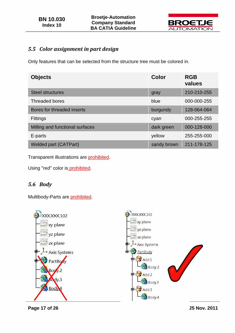
Only features that can be selected from the structure tree must be colored in.
Transparent illustrations are prohibited. Using "red" color is prohibited.
5.6 Body
Multibody-Parts are prohibited.
Objects Color RGB values
Steel structures gray 210-210-255
Threaded bores blue 000-000-255
Bores for threaded inserts burgundy 128-064-064
Fittings cyan 000-255-255
Milling and functional surfaces dark green 000-128-000
E-parts yellow 255-255-000
Welded part (CATPart) sandy brown 211-178-125
BN 10.030 Index 10
Broetje-Automation Company Standard BA CATIA Guideline
Page 18 of 26
25 Nov. 2011
5.7 Boolesche operations
Bodies must not be assembled using the "Assemble" command.
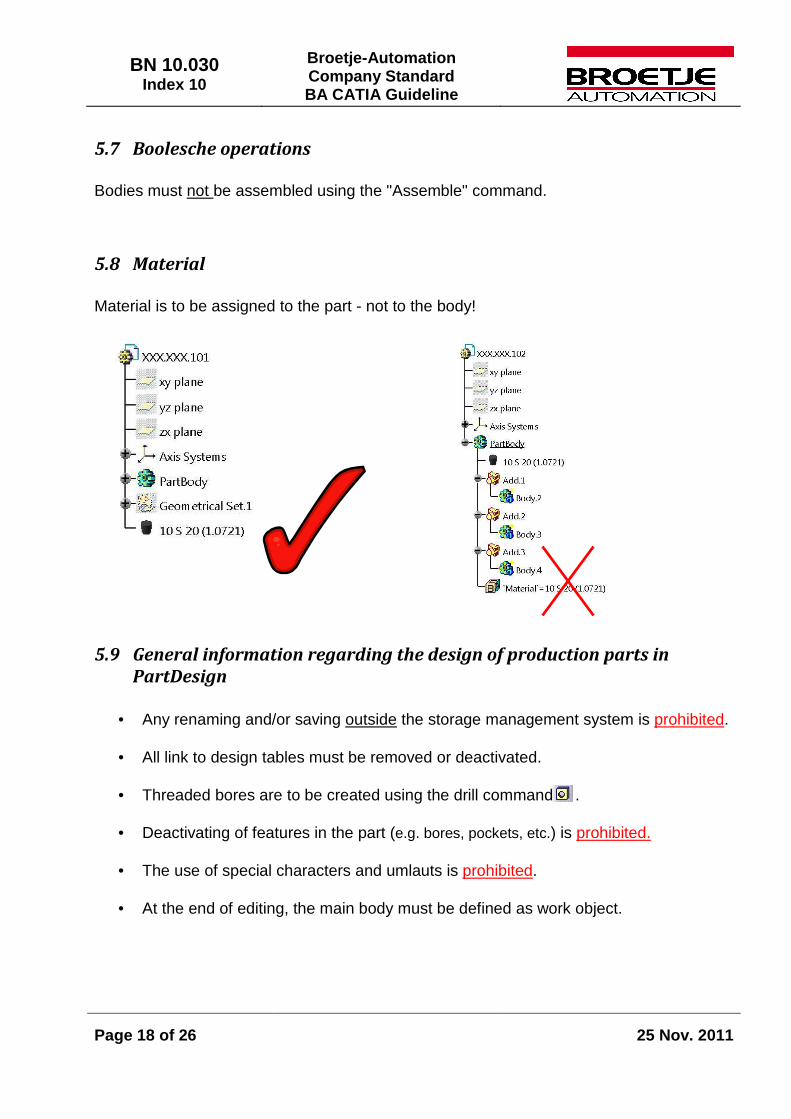
5.8 Material
Material is to be assigned to the part - not to the body!
5.9 General information regarding the design of production parts in
PartDesign
• Any renaming and/or saving outside the storage management system is prohibited.
• All link to design tables must be removed or deactivated.
• Threaded bores are to be created using the drill command .
• Deactivating of features in the part (e.g. bores, pockets, etc.) is prohibited.
• The use of special characters and umlauts is prohibited.
• At the end of editing, the main body must be defined as work object.

BN 10.030 Index 10
Broetje-Automation Company Standard BA CATIA Guideline
Page 19 of 26
25 Nov. 2011
6 Mirroring Before creating mirrored parts, it must be ensured that the part is truly mirror symmetric. Creating drawings of mirrored CATPart components or references such as "part XY mirrored" or the like are not allowed. The following procedure is to be used to create or display mirrored parts:
• Save the part to be mirrored with a new file name and mirror the body with "Symmetry".
The new part receives an own drawing number and an own new drawing.
Fig.: Original
Fig.: Copy with symmetry
BN 10.030 Index 10
Broetje-Automation Company Standard BA CATIA Guideline
Page 20 of 26
25 Nov. 2011
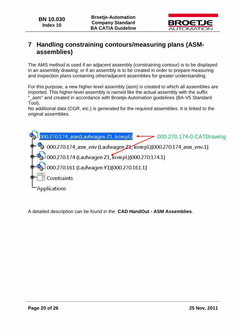
7 Handling constraining contours/measuring plans (ASM-assemblies)
The AMS method is used if an adjacent assembly (constraining contour) is to be displayed in an assembly drawing; or if an assembly is to be created in order to prepare measuring and inspection plans containing other/adjacent assemblies for greater understanding. For this purpose, a new higher-level assembly (asm) is created to which all assemblies are imported. This higher-level assembly is named like the actual assembly with the suffix "_asm" and created in accordance with Broetje-Automation guidelines (BA-V5 Standard Tool). No additional data (CGR, etc.) is generated for the required assemblies. It is linked to the original assemblies.
A detailed description can be found in the CAD HandOut - ASM Assemblies.
000.270.174-0.CATDrawing
BN 10.030 Index 10
Broetje-Automation Company Standard BA CATIA Guideline
Page 21 of 26
25 Nov. 2011
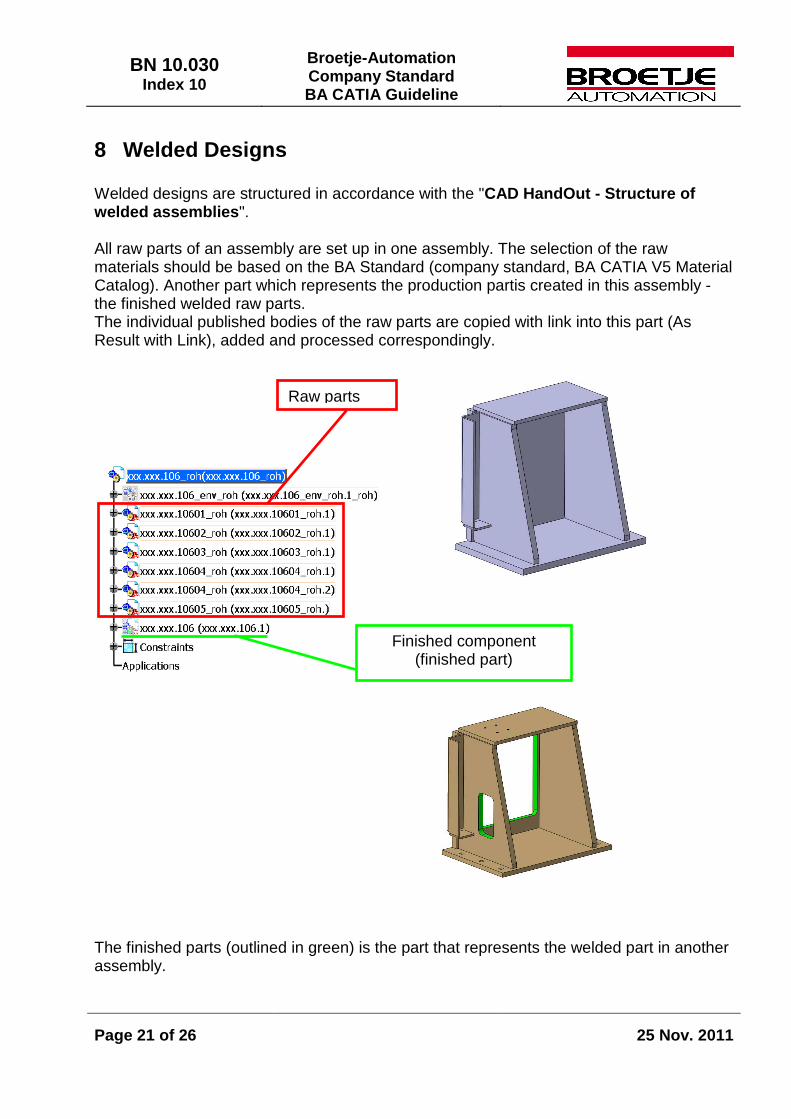
8 Welded Designs Welded designs are structured in accordance with the "CAD HandOut - Structure of welded assemblies". All raw parts of an assembly are set up in one assembly. The selection of the raw materials should be based on the BA Standard (company standard, BA CATIA V5 Material Catalog). Another part which represents the production partis created in this assembly - the finished welded raw parts. The individual published bodies of the raw parts are copied with link into this part (As Result with Link), added and processed correspondingly.
The finished parts (outlined in green) is the part that represents the welded part in another assembly.
Raw parts
Finished component (finished part)
BN 10.030 Index 10
Broetje-Automation Company Standard BA CATIA Guideline
Page 22 of 26
25 Nov. 2011
9 Generation of Drawings Information related to creating drawings can be found in the "BA_Design Guideline BN 10.010".
1) The required standard texts/weld stamps are filed in the Broetje-Automation standard catalog. Standard texts are to be inserted in edit view. It must be ensured, that the current drawing sheet is active when standard texts and stamps are inserted, i.e. the texts must not be inserted in a derived view. If 2D components from the catalog are inserted into the drawing, all existing links between the 2D-components and their corresponding references in the catalog must be deleted using the "explode 2D components" function!
2) Drawings must only be created with the Broetje-Automation drawing frame (called up via the BA standard macro).
3) The geometry of all parts in 2D views must be clearly recognizable.
4) The illustration of different geometric views (regardless of different AMS drawing numbers) of a component one the same drawing (tabular drawing) is prohibited.
5) Specifications such as "part XY mirrored" or the like for mirrored geometries are not allowed.
6) Every component must have an isometric view (scaled down illustration allowed).
7) Single part/sub-assembly drawings must only be created from the corresponding CATPart/sub-assembly (part/sub-assembly is opened in a separate window) - not from the higher-level assembly.
8) The scale must not be applied on the drawing but on the single separate drawing views.
9) The model geometries and drawing geometries must be identical, i.e. geometry changes in drawings and the manual creation of geometries is prohibited.
10) Bores are always to be dimensioned via the bore itself - under no circumstances
via axes or center lines.
11) Threaded inserts are identified by "text with reference line". Example: Ensat M5 or 3x Ensat M5
12) Locked views are only allowed as auxiliary views in assembly drawings.
BN 10.030 Index 10
Broetje-Automation Company Standard BA CATIA Guideline
Page 23 of 26
25 Nov. 2011
10 BA Catalogs
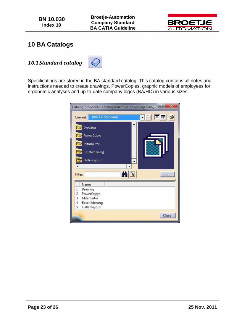
10.1 Standard catalog
Specifications are stored in the BA standard catalog. This catalog contains all notes and instructions needed to create drawings, PowerCopies, graphic models of employees for ergonomic analyses and up-to-date company logos (BA/HC) in various sizes.

BN 10.030 Index 10
Broetje-Automation Company Standard BA CATIA Guideline
Page 24 of 26
25 Nov. 2011
10.2 Material catalog
All materials approved by Broetje-Automation are filed in the BA_material-catalog. It is divided into following sections:
• Steel - For information on use, please refer to material list for heat treatment,steels for turned and milled parts.
• Steel - Preferred series for welded assemblies • Aluminum, weldable - Refer to material list for use • Aluminum, machinable - Refer to material list for use • Bulk purchase part – Material used to manipulate the density of heterogeneous materials in
purchase parts • Stock material • Plastics • Other – Should only be used during the draft phase
Material must always be assigned to the part, not to the main body. It is imperative that the user assigns materials taken from the material catalog to all single and welded parts (including raw assemblies) as the material is read and entered into the title block by the EDM system.
11 Handling Standard and Purchase Parts (internal)
11.1 Standard parts
Standard parts are set up by the CAD/EDM team specifying the applicable standard(s) and dimensions. These parts are then made available in the catalog. Please do not attach models. Send an e-mail to: [email protected]
BN 10.030 Index 10
Broetje-Automation Company Standard BA CATIA Guideline
Page 25 of 26
25 Nov. 2011
11.2 Purchase parts
Purchase parts are created in accordance with the following HandOuts from the the CAD/EDM- Portal: - CAD HandOut / Creating purchase parts - EDM HandOut - UseCase purchase part setup
12 Quality of Data Data is reviewed according to project-specific criteria on one hand (specific content and product structure pursuant to project requirements) and general criteria on the other hand (using the Q-Checker). Project-related examination content is to be documented at the beginning of the project. The following points must generally be verified and mistakes/errors must be corrected prior to data release (erroneous data generated by external offices will be returned for correction). The internal BA checklist may be made available to external offices upon request.
• CATDUA run must be recorded.
• Q-Ch3cker run must be recorded.
• Assemblies must be up-to-date.
• Assemblies must be positioned.
• There must not be any collisions.
• The controlling geometry must be fully functional.
• Naming / designation comply with the guideline.
• Storage location must comply with the guideline.
• Data must be linked as specified in the guideline.
The Q-checker test is based on the most current test profiles made available by BRÖJTE-Automation.
BN 10.030 Index 10
Broetje-Automation Company Standard BA CATIA Guideline
Page 26 of 26
25 Nov. 2011
13 External Offices External offices must create and deliver CATIA models in the Broetje-Automation environment. For that purpose, Broetje-Automation makes a CATIA environment available to external offices which can be downloaded from the FTP server (access data required). You will receive the required access authorization for the installation data on the FTP server from our CAD/EDM team. On the server you will find all documents necessary for the installation and the execution of the tasks - sample data, installation files, the Broetje-Automation environment and the Broetje-Automation catalog. The documents "OM-Hardware and Software Requirements" and "Catia V5R18 Installation with Airbus Package and Broetje-Automation environment" are relevant for the administration and the installation; the remaining documents are relevant for the design. Purchase parts are to be taken from the Broetje-Automation catalog (n:/katalog/cdb/kaufteile/...). Purchase parts that are not included in the Broetje-Automation catalog (after checking if the parts are meanwhile available on the FTP server), must either be modeled by the design engineer or be obtained from the manufacturer. These parts must then be stored with the file name and the prefix "transfer_" in a separate directory. The "transfer_" parts are submitted with the remaining data. However, if it is already clear that the purchase parts are used before the data is submitted, the "transfer_" parts may be submitted to Broetje-Automation in order to have them added in the catalog. Purchase parts are created in accordance with the "CAD HandOut - Creating Purchase Parts" which can be found on the FTP server. Standard parts (screws, pins, etc.) are set up by our CAD/EDM team and are made available in the catalog (n:/katalog/cdb/normteile/...). Please notify our CAD/EDM team by e-mail if a standard part is not available in the catalog and include the corresponding standard and dimensions. External offices are obliged to download the latest Broetje-Automation catalog from the FTP server every week and to either store it on N:\ drive or to update the catalog directory from the FTP server. You may also contact our CAD/EDM team for questions: Tel.: +49 (0)4402 / 966-460 [email protected]