virgo boards/virgo...iii thank you for selecting and purchasing the virgo serverboard. this...
TRANSCRIPT

UM_Virgo_v3.1_102218
VirgoServer Motherboard
User's Manual
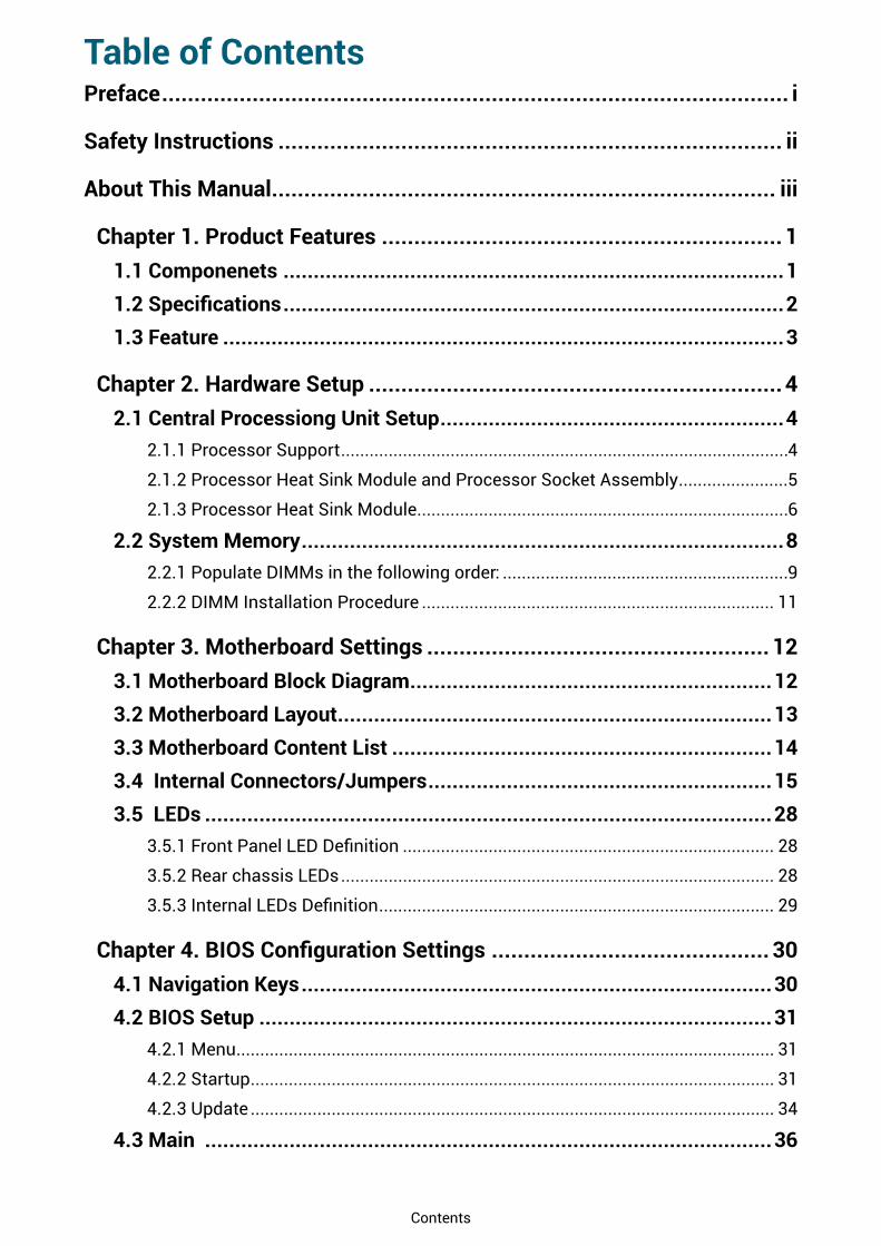
Contents
Table of ContentsPreface ������������������������������������������������������������������������������������������������� i
Safety Instructions ������������������������������������������������������������������������������ ii
About This Manual ������������������������������������������������������������������������������ iii
Chapter 1� Product Features ��������������������������������������������������������������11�1 Componenets �����������������������������������������������������������������������������������11.2 Specifications �����������������������������������������������������������������������������������21�3 Feature ���������������������������������������������������������������������������������������������3
Chapter 2� Hardware Setup ����������������������������������������������������������������42�1 Central Processiong Unit Setup ���������������������������������������������������������4
2.1.1 Processor Support ..............................................................................................4
2.1.2 Processor Heat Sink Module and Processor Socket Assembly .......................5
2.1.3 Processor Heat Sink Module ..............................................................................6
2�2 System Memory ��������������������������������������������������������������������������������82.2.1 Populate DIMMs in the following order: ............................................................9
2.2.2 DIMM Installation Procedure .......................................................................... 11
Chapter 3� Motherboard Settings ����������������������������������������������������� 123�1 Motherboard Block Diagram ������������������������������������������������������������123�2 Motherboard Layout ������������������������������������������������������������������������133�3 Motherboard Content List ���������������������������������������������������������������143�4 Internal Connectors/Jumpers ���������������������������������������������������������153�5 LEDs ����������������������������������������������������������������������������������������������28
3.5.1 Front Panel LED Definition .............................................................................. 28
3.5.2 Rear chassis LEDs ........................................................................................... 28
3.5.3 Internal LEDs Definition ................................................................................... 29
Chapter 4. BIOS Configuration Settings ������������������������������������������� 304�1 Navigation Keys ������������������������������������������������������������������������������304�2 BIOS Setup �������������������������������������������������������������������������������������31
4.2.1 Menu ................................................................................................................. 31
4.2.2 Startup .............................................................................................................. 31
4.2.3 Update .............................................................................................................. 34
4�3 Main ����������������������������������������������������������������������������������������������36

4.3.1 Main .................................................................................................................. 36
4�4 Advanced ����������������������������������������������������������������������������������������374.4.1 Peripheral Configuration ................................................................................. 37
4.4.2 Video Configuration ......................................................................................... 37
4.4.3 Socket Configuration ....................................................................................... 37
4.4.4 PCH Configuration ........................................................................................... 41
4.4.5 H2o IPMI Configuration ................................................................................... 45
4.4.6 H2o Event Log Config Manager ...................................................................... 46
4�5 Security ������������������������������������������������������������������������������������������474.5.1 Security ............................................................................................................ 47
4�6 Power ���������������������������������������������������������������������������������������������484.6.1 Power ............................................................................................................... 48
4�7 Boot ������������������������������������������������������������������������������������������������494.7.1 Boot .................................................................................................................. 49
4�8 Exit �������������������������������������������������������������������������������������������������504.8.1 Exit .................................................................................................................... 50
Chapter 5. BMC Configuration Settings �������������������������������������������� 515�1 Method 1 (Use the BIOS Setup) �������������������������������������������������������515�2 Method 2 (Use a Dos Tool - Syscheck) ��������������������������������������������545�3 Connect to BMC ������������������������������������������������������������������������������565�4 Updating BMC Firmware �����������������������������������������������������������������60
Chapter 6� Technical Support ����������������������������������������������������������� 61

Copyright © 2017 AIC, Inc. All Rights Reserved.
This document contains proprietary information about AIC products and is not to be disclosed or used except in accordance with applicable agreements.

Document Release History
Release Date Version Update Content
March2017 1 User's Manual release to public.
July2017 2 1. Gramnatical Error
2. Connector and Jumper
September 2018 3 1. BIOS update
2. New Cover
October2018 3.1 Specification update

i
Copyright
No part of this publication may be reproduced, stored in a retrieval system, or transmitted in any form or by any means, electronic, mechanical, photo-static, recording or otherwise, without the prior written consent of the manufacturer.
Trademarks
All products and trade names used in this document are trademarks or registered trademarks of their respective holders.
Changes
The material in this document is for information purposes only and is subject to change without notice.
Warning
1. A shielded-type power cord is required in order to meet FCC emission limits and also to prevent interference to the nearby radio and television reception. It is essential that only the supplied power cord be used.
2. Use only shielded cables to connect I/O devices to this equipment.3. You are cautioned that changes or modifications not expressly approved by the
party responsible for compliance could void your authority to operate the equipment.
Disclaimer
AIC shall not be liable for technical or editorial errors or omissions contained herein. The information provided is provided "as is" without warranty of any kind. To the extent permitted by law, neither AIC or its affiliates, subcontractors or suppliers will be liable for incidental, special or consequential damages including downtime cost; lost profits; damages relating to the procurement of substitute products or services; or damages for loss of data, or software restoration. The information in this document is subject to change without notice.
Preface

ii
When installing, operating, or performing maintenance on this equipment, the following safety precautions should always be observed in order to reduce the risk of fire, electric shock, and personal injury.
Read and understand all instructions.• Observe warnings and instructions marked on the product.• For proper mounting instructions, please consult the User’s Manual provided with this
product.• Do NOT place this product on an unstable cart, stand, table or uneven surface that
might cause the product to fall and sustain serious damage.• Only install the equipment identified in the User’s Manual. Use of other equipment
could cause improper connection of circuitry and may result in fire or personal injury.• This product should only be operated with the type of power source indicated on the
marked label. If you are uncertain about which type of power supply is used in your area, consult your dealer or local Power Company.
• Disconnect the power supply module before removing power from the system.Unplug this product from the wall outlet before cleaning. Use a damp cloth for cleaning. Do not use liquid cleaners or aerosol cleaners.• Do not use this product near a water source, such as a faucet.• Never spill liquids of any kind on this product.• Never shove objects of any kind into this product’s open slots, as they may touch
dangerous voltage points or short out parts and could result in fire or electric shock.• Do not block or cover slots and openings in this unit, as they were made for ventilation
and prevent this unit from overheating. Do not place this product in a built-in installation unless proper ventilation is available.
• Do not disassemble this product. This product should only be taken apart by trained personnel. Opening or removing covers and circuit boards may expose you to electric shock or other risks. Incorrect reassembly can also cause electric shock when the unit is subsequently used.
• Risk of explosion is possible if battery is replaced with an incompatible type. Dispose of used batteries accordingly.
• This product is equipped with a three-wire grounding type plug, a plug with a third (grounding) pin. As a safety feature, this plug is intended to fit only into a grounding type power outlet. If you are unable to insert the plug into the outlet, contact your electrician to replace the outlet. Do not remove the grounding type plug or use a 3-Prong To 2-Prong Adapter to circumvent the safety feature; doing so may result in electric shock and/or damage to this product.
Safety Instructions
iii
Thank you for selecting and purchasing the Virgo Serverboard.This user's manual is provided for professional technicians to perform easy hardware setup, basic system configurations, and quick software startup. This document pellucidly presents a brief overview of the product design, device installation, and firmware settings for the Virgo motherboard. For the latest version of this user's manual, please refer to the AIC website: http://www.aicipc.com/en/productdetail/20855.
Chapter 1 Product FeaturesThis chapter delivers the overall layout of the product, including the fundamental components on the motherboard, design specifications, and noteworthy features. Virgo is an ideal server grade motherboard that is specifically designed to accommodate diverse enterprises for managing heavy workloads, databases, nearline applications, and cloud deployments. This product supports the Intel® Xeon® Scalable Processors and Socket P0 (LGA-3647) with a memory support 12 DDR4 2400/2666 MHz accross 6 channels per CPU.
Chapter 2 Hardware SetupThis chapter displays an easy installation guide for assembling the CPU(Central Processing Unit) and memory chip. Utmost caution for proceeding to set up the hardware is highly advised. The components on the motherboard are highly fragile and vulnerable to exterior influence. Do not attempt to endanger the device by placing the device in a potentially unstable or hazardous surroundings, including positioning the device on an uneven grounds or humid environments.
Chapter 3 Motherboard SettingsThis chapter elaborates the overall layout of the server motherboard, including multifarious connectors, jumpers, and LED descriptions. These descriptions assist users to configure different settings and functions of the motherboard, as well as to confirm the location of each connector and jumper.
Chapter 4 BIOS Configuration SettingsThis chapter introduces the key features of BIOS, including the descriptions and option keys for diverse functions. These details provide users to effortlessly navigate and configure the input/output devices.
Chapter 5 BMC Configuration SettingsThis chapter illustrates the diverse functions of IPMI BMC, including the details on logging into the web page and assorted definitions. These descriptions are helpful in configuring various functions through Web GUI without entering the BIOS setup. For more information of BMC configurations, please refer to IPMI BMC (Aspeed2500) User's Manual for a more detailed description.
Chapter 6 Technical SupportFor more information or suggestion, please contact the nearest AIC corporation representative in your district or visit the AIC website: http://www.aicipc.com/tw/index. It is our greatest honor to provide the best service for our customers.
About This Manual
1
Chapter 1. Product FeaturesVirgo User Manual
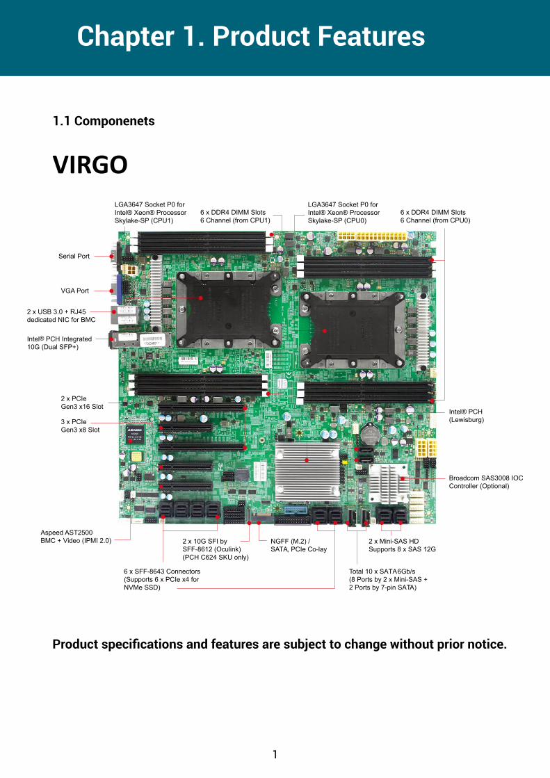
VIRGO
Product specifications and features are subject to change without prior notice.
Serial Port
VGA Port
2 x USB 3.0 + RJ45dedicated NIC for BMC
Intel PCH Integrated10G (Dual SFP+)
Aspeed AST2500BMC + Video (IPMI 2.0)
6 x SFF-8643 Connectors (Supports 6 x PCIe x4 for NVMe SSD)
2 x 10G SFI by SFF-8612 (Oculink)
NGFF (M.2) / SATA, PCIe Co-lay
3 x PCIe Gen3 x8 Slot
2 x PCIe Gen3 x16 Slot
Total 10 x SATA 6Gb/s(8 Ports by 2 x Mini-SAS + 2 Ports by 7-pin SATA)
2 x Mini-SAS HD Supports 8 x SAS 12G
Broadcom SAS3008 IOC Controller (Optional)
(Lewisburg)
6 x DDR4 DIMM Slots6 Channel (from CPU0)
LGA3647 Socket P0 for
Skylake-SP (CPU0)6 x DDR4 DIMM Slots6 Channel (from CPU1)
LGA3647 Socket P0 for
Skylake-SP (CPU1)
Spica User Manual Chapter 1. Product FeaturesChapter 1� Product Features
1�1 Componenets

2
Chapter 1. Product FeaturesVirgo User Manual
1.2 Specifications
System
Processor Support
Intel® Xeon® Scalable Processors (Platinum, Gold, Silver, Bronze)
UPI Speeds 9.6 GT/s, 10.4 GT/s
Socket Type Socket P0 (LGA-3647 Socket)
System Memory
A) 6 x memory channels per CPU, 1 x DIMM per channel
B) 12 x DIMM slots support: DDR4 2666/2400 RDIMM/LRDIMM - up to 192GB RDIMM SRx4 - up to 384GB RDIMM DRx4 - up to 1536GB RDIMM 3DS 8Rx4 - up to 768GB LRDIMM QRx4 - up to 1536GB LRDIMM 3DS 8Rx4
ExpansionSlots
• 2 x PCIe Gen3 x16 slots • 3 x PCIe Gen3 x8 slots• 6 x SFF-8643 each supports PCIe Gen3 x4• 1 x NGFF (M.2) supports PCIe Gen3 x4 / SATA
System BIOS
BIOS Type Insyde UEFI BIOS
BIOS Features
• ACPI• PXE• WOL• AC loss recovery• IPMI KCS interface• SMBIOS• Serial console redirection
• BIOS Recovery Mode• SRIOV
On-board Devices
SATA
Intel® Lewisburg PCH on-chip solution• 8 x SATA 6.0 Gb/s (by 2 x mini-SAS) • 2 x SATA 6.0 Gb/s (by 2 x SATA 7 pin)• Broadcom SAS IOC SAS3008 supports up to 8 ports 12G SAS via 2 x mini-SAS HD (optional)
IPMI
Aspeed AST2500 Advanced PCIe Graphics & Remote Management Processor• Baseboard Management Controller• Intelligent Platform Interface 2.0 (IPMI 2.0)• iKVM, Media Redirection, IPMI over LAN, Serial over LAN• SMASH Support• HTML5
On-board Devices
Network Controller
• Intel® PCH (Lewisburg) Integrated 10GbE LAN Controller with dual SFP+ rear connectors
(KR/SFI/XFI) or 1GbE (KX) by onboard header (optional by PCH C624 SKU)• Realtek RTL8201E GbE Ethernet for BMC dedicated management port
Graphics
Aspeed AST2500 Advanced PCIe Graphics & Remote Management Processor• PCIe VGA/2D Controller• 1920x1200@60Hz 32bpp
Input/Output
Serial ATA10 x SATA 6.0 Gb/s ports• 8 x SATA 6.0 Gb/s (by 2 x mini-SAS)• 2 x SATA 6.0 Gb/s (by 2 x SATA 7 pin)
LAN
• 2 x 10GbE SFP+• 1 x internal SFF-8612 (Oculink) supports dual ports: 10G KR/SFI/XFI or 1G KX (optional by PCH C624 SKU)• 1 x GbE RJ45 dedicated to BMC management
USB• 2 x USB3.0 double-stack Type-A connectors• 1 x USB internal pin-header to support 2 x USB3.0/USB2.0
VGA• 1 x external VGA port• 1 x internal VGA pin-header (share with external VGA port)
Serial Port• 1 x external DB-9 COM port• 2 x internal COM pin-headers
Other• 1 x NGFF (M.2) supports PCIe Gen3 x4 / SATA• 1 x TPM 2.0 onboard
Additional Information
SAS (Optional)• 2 x mini-SAS HD (SFF-8643) support up to 8 ports SAS 12 Gb/s

3
Chapter 1. Product FeaturesVirgo User Manual
The Virgo server board integrates two Intel® Xeon® Scalable Processors and 12 DDR4 DIMM to offer support for greater capacity, durability, and efficiency for our customers. Featuring the Intel® Xeon® Scalable Processors, which is emphasized for its compelling orchestration, security, and productivity, this product enhances these advantages by im-plementing with AIC-patented Max I/O and Quick Path extension(QPX) to provide greater bandwidth and utilization.
In addition to integrating more memory capacity and system expansion to the server board, Libra provides immediate and efficient management with Onboard Baseboard Man-agement Controller and greater I/O extension. Featuring IPMI 2.0 and Aspeed AST2500 Advanced PCIe Graphics, the server board offers support for iKVM, Media Redirection, key-board controller style, IPMI over LAN, and Serial over LAN.
• Supports two Intel® Xeon® Scalable Processors for highest server performance and improved power efficiency
• Supports 2 x PCIe Gen3 x16 slots+ 3 x PCIe Gen3 x8 slots + 6 x SFF-8643 each sup-ports PCIe Gen3 x4.
• Supports one NGFF(M.2) with PCIe Gen3 x4/SATA co-design
• Broadcom SAS3008 SAS/SATA/I/O Controller for 12Gb/s SAS
• Onboard dual ports 10GbE SFP+ and optional two configurable ports support 10GbE (KR/SFI/XFI) or 1Gb/E (KX) by internal connector supported by Intel®Lewisburg PCH
• Onboard Baseboard Management Controller fro system management and IPMI control
• Embedded components for 5+ year long life
1�3 Feature

4
Chapter 2. Hardware SetupVirgo User Manual
2�1�1 Processor Support
The server board includes two processor sockets (LGA3647) that provides one or two processors of the Intel® Xeon® Processor Scalable Family and supports a Thermal Design Power (TDP) of up to 165W on selected models.
2�1 Central Processiong Unit Setup
Spica User ManualChapter 2� Hardware Setup

5
Chapter 2. Hardware SetupVirgo User Manual
2�1�2 Processor Heat Sink Module and Processor Socket Assembly
Each processor socket on the server board is pre-assembled with a loading mechanism that is designed to secure the Processor Heat Sink Module (PHM) to the server board as shown below.
WARNINGPrevious generations of the Intel Xeon Processors and heatsinks are not compatible with the Intel Server Board S2600BP Product Family. Processor installation requires that the proces-sor be attached to the installation onto the server board.

6
Chapter 2. Hardware SetupVirgo User Manual
2�1�3 Processor Heat Sink Module
The PHM refers to the sub-assembly where the heat sink and processor are clipped together onto the server board prior to installation. The PHM consists of the components shown below.
Processor Heat Sink Module (PHM) Sub-Assembly
Processor Heatsink Module (PHM)

7
Chapter 2. Hardware SetupVirgo User Manual
The PHM sits level with the processor socket assembly. The PHM is NOT installed properly if it does not sit level with the processor socket assembly. Once the PHM is seated over the processor socket assembly, the four heat sink torque screws must be tightened in order as shown below.
Processor Heat Sink – Top View with Screw Tightening Order
NOTEFailure to tighten the heatsink screws in the specified order may cause damage to the processor socket assembly. Heat sink screws should be tighted to 12 in-lbs torque according to the indicated order on the top of the heatsink label.

8
Chapter 2. Hardware SetupVirgo User Manual
This server board supports up to twelve DDR4 2400 and 2666 Registered ECC DRAM/ Load-Reduced DIMM (LRDIMM).
CPU 0CPU 1CPU 1
CPU 0
JDIMME0JDIMME0JDIMMF0JDIMMF0
JDIMMD0
JDIMMC0JDIMMB0JDIMMA0
JDIMMC0JDIMMB0JDIMMA0
JDIMML0JDIMMK0JDIMMJ0
JDIMML0JDIMMK0JDIMMJ0
JDIMMG0JDIMMH0JDIMMI0
JDIMMG0JDIMMH0JDIMMI0
SFF-8643 � SFF-8643 �
PCIE5
PCIE4
PCIE3
PCIE2
PCIE1
2�2 System Memory
NOTE-In Virgo case, the lanes from CPU#0 are routed to PCIe slots 1 & 5 and onboard SFF-
8643.-The lanes from CPU#1 are routed to PCIe slots 2/3/4 and the onboard SFF-8643.

9
Chapter 2. Hardware SetupVirgo User Manual
2�2�1 Populate DIMMs in the following order:
DIMM Numbers DIMM ARRANGMENT
2 DIMMs CPU1 CPU0
JDIMM_L0 JDIMM_C0
JDIMML0 JDIMMC0JDIMMK0 JDIMMB0JDIMMJ0 JDIMMA0
JDIMMG0 JDIMMD0JDIMMH0 JDIMME0JDIMMI0 JDIMMF0
CPU 1CPU 1 CPU 0CPU 0
JDIMML0 JDIMMC0JDIMMK0 JDIMMB0JDIMMJ0 JDIMMA0
JDIMMG0 JDIMMD0JDIMMH0 JDIMME0JDIMMI0 JDIMMF0
CPU 1CPU 1 CPU 0CPU 04 DIMMs
CPU1 CPU0
JDIMM_L0 JDIMM_C0
JDIMM_J0 JDIMM_A0
JDIMML0 JDIMMC0JDIMMK0 JDIMMB0JDIMMJ0 JDIMMA0
JDIMMG0 JDIMMD0JDIMMH0 JDIMME0JDIMMI0 JDIMMF0
CPU 1CPU 1 CPU 0CPU 06 DIMMs
CPU1 CPU0
JDIMM_L0 JDIMM_C0
JDIMM_J0 JDIMM_A0
JDIMM_I0 JDIMM_F0
JDIMML0 JDIMMC0JDIMMK0 JDIMMB0JDIMMJ0 JDIMMA0
JDIMMG0 JDIMMD0JDIMMH0 JDIMME0JDIMMI0 JDIMMF0
CPU 1CPU 1 CPU 0CPU 08 DIMMs
CPU1 CPU0
JDIMM_L0 JDIMM_C0
JDIMM_J0 JDIMM_A0
JDIMM_G0 JDIMM_D0
JDIMM_I0 JDIMM_F0

10
Chapter 2. Hardware SetupVirgo User Manual
JDIMML0 JDIMMC0JDIMMK0 JDIMMB0JDIMMJ0 JDIMMA0
JDIMMG0 JDIMMD0JDIMMH0 JDIMME0JDIMMI0 JDIMMF0
CPU 1CPU 1 CPU 0CPU 0CPU1 CPU0
JDIMM_L0 JDIMM_C0JDIMM_K0 JDIMM_B0JDIMM_J0 JDIMM_A0JDIMM_G0 JDIMM_D0JDIMM_I0 JDIMM_F0
10 DIMMs
JDIMML0 JDIMMC0JDIMMK0 JDIMMB0JDIMMJ0 JDIMMA0
JDIMMG0 JDIMMD0JDIMMH0 JDIMME0JDIMMI0 JDIMMF0
CPU 1CPU 1 CPU 0CPU 0
CPU1 CPU0JDIMM_L0 JDIMM_C0JDIMM_K0 JDIMM_B0JDIMM_J0 JDIMM_A0JDIMM_G0 JDIMM_D0JDIMM_H0 JDIMM_E0JDIMM_I0 JDIMM_F0
12 DIMMs

11
Chapter 2. Hardware SetupVirgo User Manual
2�2�2 DIMM Installation Procedure
This server board supports 12 DIMM memory slots with 6 channel per CPU.
2�2�1 DIMM Installation
Step 1 Unlock the dimm socket by pressing the retaining clips outward.
Step 2 Insert the memory module into the slot. Make sure that the dimm notch is
accurately positioned.
Step 3 Close the retaining clips to complete installation.
DIMM notch

12
Chapter 3. Motherboard SettingsVirgo User Manual
This section describes the jumpers, internal connectors and internal LEDs setting on Virgo motherboard. The motherboard layout and important jumper settings are listed below.
3�1 Motherboard Block Diagram
DMI GEN3@8GT/s
LGA3647-0 Socket
SPI FlashW25Q64BVSSIG
CPU TDP 145W
Platform Environment Control Interface(PECI)
DMI3 x 4
S25FL256SAGMFI001Flash
Debug port
USB#3USB#2
ECC DDR4 (1866/2133/2400/2667)
CPU0
MUX
USB#0USB#1
DIMM #A0DIMM #B0
DIMM #C0DIMM #D0
DIMM #E0
CPU0_VRD VR13
XDP
Skylake-SP(Cannonlake-SP)
CPU1
LGA3647-0 Socket
DIMM #G0
CPU TDP 145W
DIMM #I0 DIMM #K0DIMM #L0
ECC DDR4 (1866/2133/2400/2667)
TDP 19W
Lewisburg-4 PCH
SATAPort #0~9
SATA#0SATA#1
SATA#2SATA#3
PCIe slot X8 (Support NTB)
PCIe slot X16
Port3(IOU2)
PCI-E GEN3 @8GT/s X8
Port2(IOU1)
PCI-E GEN3 @8GT/s X16
Port3(IOU2) Port1(IOU0)
LPC/eSPI
Platform Environment Control Interface(PECI)
@6Gb/s
PCIe5
PCIe4(NTB)
PCIe1(NTB)
PCIe2
P1 CH3/DIMM0/A0
P1 CH5/DIMM0/A8
P1 CH4/DIMM0/A4
P1 CH0/DIMM0/A0
P1 CH1/DIMM0/A4
P0 CH0/DIMM0/A0
P0 CH1/DIMM0/A4
P0 CH2/DIMM0/A8
P0 CH3/DIMM0/A0
P0 CH4/DIMM0/A4
CPU0
CPU1
Placement
SATA#6SATA#7
USB2.0 Port #0~3@5Gb/s
USB3.0 Port #0~3
DIMM #F0DIMM #H0 DIMM #J0
CPU1_VRD VR13
PCIe slot2
PCIe slot3
PCIe slot4
PCIe slot5
Port2(IOU1)
NGFF M.2 2242/2280
MUX x1
PCIE x4 or SATA x1
PCI-E GEN3 @8GT/s X4 & SATA @6Gb/s
SATAPort #10@6Gb/s
SATA#8SATA#9
P0 CH5/DIMM0/A8
P1 CH2/DIMM0/A8P
CIe3
PCI Express x 4
PCI Express x 16
PCIe slot X16
PCI-E GEN3 @8GT/s X16
LSISAS3008
SASPort x4
@12Gb/sSASPort x4
@12Gb/s
PCI Express x 16
S25FL256SAGMFI001
NVSRAMCY14V101LA-BA25
FlashUART0
Debug portICE0
Debug port
PCIe slot X8
PCI-E GEN3 @8GT/s X8
Port1(IOU0)
LSISAS3008
NGFF M.2 2242/2280
PCIE x 8PCI-E GEN3@8GT/s
SFF-8643
SFF-8643PCI Express x 4
Port1a(IOU0)
Port1c(IOU0)
Port1d(IOU0)
PCI Express x 8Port3c(IOU2)
Port2a(IOU1)
Port2a(IOU1)
Skylake-SP(Cannonlake-SP)
Port3a(IOU2)
SFF-8643
SFF-8643
SFF-8643
SFF-8643
PCI Express x 4
SATA#4
SPI
NUVOTONNPCT650
SPI FlashW25Q128V
TPM 2.0
(Internal Box Header )
Edge Connector
RJ45 x1
SPI
SPI2
USB(X2)RMII
Aspeed AST2500
VGA CONN
VGA Pin Header
PCI Express x 1
COM1(DB-9 CONN)
Pin HeaderBMC Debug
Box Header
COM2
(1x3 pin)
JCOM4(2x5 pin)
USB(X2)
ADM213
ADM213
COM5
USB2.0 Port #4~5
Box Header(2x5 pin)
SFP x2
NCSI
ADM213
COM1
AST_USB Port #0~1 to PCH Port #4~5
EDY4016AABG-DR-F-DDDR4 x16
COM4LCMPin Header(1x5 pin)
Secure boot key
PCI Express x 8
Port3c(IOU2)PCI Express x 8
UPIUPI @10.4GT/s
UPI1
UPI0
UPI0
UPI1 UPI
UPI @10.4GT/s
SFF-8643
SFF-8643
PCIe slot X8 (Support NTB)
PCIe slot1
PCI Express x 8Port3a(IOU2)
PCI-E GEN3 @8GT/s X8
SFF-8643
SFF-8643
SFF-8643
SFF-8643
SFF-8643
SFF-8643
SFF-8643
SFF-8643Port1a(IOU0)PCI Express x 4
Port1b(IOU0)PCI Express x 4
Port1c(IOU0)PCI Express x 4
Port1d(IOU0)PCI Express x 4
10/100Mbps dedicatemanagement port
RTL8201EL
SFIx2
SFIx2
I2C4
LM95241CIMM
LM95241CIMM-1
LM95241CIMM-2
PCH
SFP
SFF-8612
SFF-8612(SFP)
SATA#5
Chapter 3� Motherboard Settings

13
Chapter 3. Motherboard SettingsVirgo User Manual
CPU 0CPU 1CPU 1
CPU 0
1 2
4
45
6
10
11
1213
18
19
20
21 3
25
24
26
27
282932
4045 a
45 c
47
51
55
56
57
58 59 60
62
63
64
65 66
675253
54
42 41 7
14a
50 a
61
1736
31
3046 38 23 33
22
34
39
3437
35
4849 b
8
9b
9a
b45 b
a8a
15
12 Dimm Sockets
43
1 2 3 4
43
5 6
44
3�2 Motherboard Layout

14
Chapter 3. Motherboard SettingsVirgo User Manual
Connectors Location Connectors Location1 Power Supply JPWR1 34 Speaker JSPKR
2 Power Supply JPWR2 35 BIOS Recovery Mode J9
3 Power Supply JPWR3 36 ME Force Recovery Mode J3
4 Power Supply JPWR4 37 Flash Descriptor Security override J8
5 Power Supply JPWR5 38 No Reboot(Watch Dog) J26
6 SATA-DOM Power JDOM_PWR 39NTB(Non-Transparent Bridge)
JNTB
7 Front Panel JFRNT_SSI 40 PCH GPIO JPCH_GPIO8a8b Serial ATA SATA4、SATA5 41 NGFF JNGFF
9a9b MINISAS SATA0_3、SATA6_9 42 Internal
10GbE(Reserved) J7
10 VGA JVGA_INT 43 PCIE3.0 CN1~CN611 COM1 JCOM1 44 SAS3.0 CN7、CN8
12 COM4 JCOM445a45b45c
External Thermal Sensor J2、J13、J24
13 LCM JLCM(COM3) 46 BMC Debug Port Select J27
14 Front USB JUSB_INT 47 VROC Key JRAID_KEY
15 XDP CONN JCPU_XDP 48 SATA4 PIN-7 Power J10
16 DIMM Sockets JEDEC Specified DDR4 Connector 49 SATA5 PIN-7 Power J11
17 Debug Port JLPC_DP 50 PCIE Hot-Plug SMB JPCIE_HP18 ESPI Port JESPI 51 VRM SMB JSMB_VR
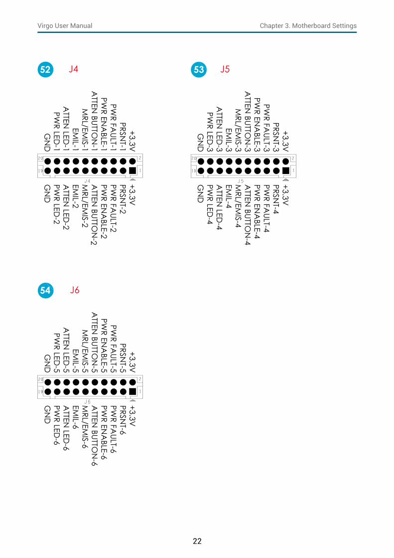
19 BMC Debug Port JBMC_DP 52 PCIE Hot-Plug Front Panel J4(CN5&CN6)
20 BMC GPIO JBMC_GPIO 53 PCIE Hot-Plug Front Panel J5(CN3&CN4)
21 SGPIO JSGPIO 54 PCIE Hot-Plug Front Panel J6(CN1&CN2)
22 SSGPIO JSSGPIO 55 CPU1 FAN CONN J123 Clear CMOS JCMOS 56 CPU0 FAN CONN J2224 BMC I2C10 JBMC_I2C10 57 PCH FAN CONN J2125 BMC IPMI JBMC_I2C1 58 FAN1A CONN J1826 Battery Socket JBAT 59 FAN1B CONN J2327 Intruder JINTRUDER 60 FAN2A CONN J1728 PMBUS JPMBUS 61 FAN2B CONN J1629 SPI ROM Socket JSPI_BIOS 62 FAN3A CONN J1530 BMC Reset JBMC_RST 63 FAN3B CONN J1431 BMC Disable JBMC_DIS 64 SAS IOC UART J20
32 BMC Buzzer JBUZZER 65 SAS IOC ACTIVITY LED J19
33 System PG Lock JPG_LOCK 66 SAS IOC ERROR LED J25
67 SAS IOC ICE J12
3�3 Motherboard Content List

15
Chapter 3. Motherboard SettingsVirgo User Manual
Connectors Location12 COM4 JCOM413 LCM JLCM(COM3)19 BMC Debug Port JBMC_DP20 BMC GPIO JBMC_GPIO21 SGPIO JSGPIO24 BMC I2C10 JBMC_I2C1025 BMC IPMI JBMC_I2C127 Intruder JINTRUDER30 BMC Reset JBMC_RST32 BMC Buzzer JBUZZER
45a45b45c
External Thermal Sensor J2、J13、J24
47 VROC Key JRAID_KEY
121319
20
21
25
24
27
32
45 a
47
301 2
3�4 Internal Connectors/Jumpers

16
Chapter 3. Motherboard SettingsVirgo User Manual
DSR
RTSC
TSRIN
C
DC
DRXDTXDD
TRG
ND
JCOM412
SW_PW
R_BTN#
SW_RST_BTN
#TXD
CRXD
CG
ND
JLCM13
BMC
_UART_TXD
5BM
C_UA
RT_RXD5
GN
D
JBMC_DP19
BMC_GPY0BMC_GPY1EXTRST#
I2C9SCLI2C9SDA
GND
JBMC_GPIO20
PCH_SCLOCKPCH_SLOADPCH_SDATAOUT0
+3.3VPCH_SDATAOUT1
GND
JSGPIO21
GNDI2C10SDAI2C10SCL
JBMC_I2C1024
I2C1SDAGNDI2C1SCLNC
JBMC_I2C125 27
BMC_BUZZER+5V
JBUZZER32
GN
D+3.3V
_DUA
LG
ND
PCH_G
PP_C10
JRAID_KEY47
HM_TD
5-HM
_TD5+
J245 a

17
Chapter 3. Motherboard SettingsVirgo User Manual
Connectors Location6 SATA-DOM Power JDOM_PWR
17 Debug Port JLPC_DP18 ESPI Port JESPI22 SSGPIO JSSGPIO40 PCH GPIO JPCH_GPIO51 VRM SMB JSMB_VR57 PCH FAN CONN J2167 SAS IOC ICE J12
6
18
40
51
57
67
17
22

18
Chapter 3. Motherboard SettingsVirgo User Manual
GN
D+5V
JDOM_PWR6
PCH_LPC
_LAD
0+3.3VPC
H_LPC_LA
D3
RST_PLTRST_NPC
H_LFRAM
E_NC
LK_24M_D
P80
GN
DPC
H_LPC_LA
D1
PCH_LPC
_LAD
2A
ST_SERIRQPC
H_LDRQ
0_NG
ND
11
JLPC_DP17
PCH_ESPI_A
LENT1_N
PCH_ESPI_RST_N
SMB_HO
ST_3V3_C
LKSM
B_HOST_3V
3_DA
TPG
PPA_PC
H
GN
DPC
H_PME_N
PCH_LPC
_CLKRUN
_NPC
H_SMI_N
+5V_A
UX
10
JESPI18
GN
DPC
H_SSDA
TAO
UT1+3.3V
PCH_SSD
ATA
OUT0
PCH_SSLO
AD
PCH_SSC
LOC
KJSSGPIO22
PCH_G
PP_C16
PCH_G
PP_C17
GN
D
JPCH_GPIO40
SMB_VR_CLKGNDSMB_VR_DAT
JSMB_VR51
GND+12VTACHPWM
J2157
ICE0_TM
SIC
E0_TDO
ICE0_TD
IN
.C.
SYS_HALT_L0
ICE0_TRST_LIC
E0_TCK
SAS3008_1V
8G
ND
N.C
.
J1267
19
Chapter 3. Motherboard SettingsVirgo User Manual
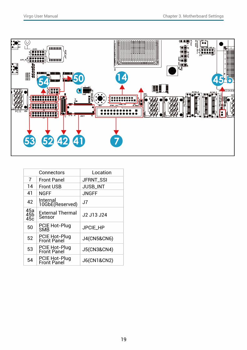
Connectors Location7 Front Panel JFRNT_SSI
14 Front USB JUSB_INT41 NGFF JNGFF
42 Internal 10GbE(Reserved) J7
45a45b45c
External Thermal Sensor J2、J13、J24
50 PCIE Hot-Plug SMB JPCIE_HP
52 PCIE Hot-Plug Front Panel J4(CN5&CN6)
53 PCIE Hot-Plug Front Panel J5(CN3&CN4)
54 PCIE Hot-Plug Front Panel J6(CN1&CN2)
5253
54
42 41 7
14a
50 a
b45 b

20
Chapter 3. Motherboard SettingsVirgo User Manual
+3.3V_D
UAL
+5V_A
UXUID
LED_O
UT#SYS_HEA
LTH#2
SYS_HEALTH#
1LA
N1_LIN
K_UPLA
N1_TRA
FFICI2C
8SDA
I2C8SC
LIN
TRUDER#
LAN
2_LINK_UP
LAN
2_TRAFFIC
PWR_LED
KEY (no pin)PW
R_LED#
+3.3VHD
_LED#
SW_PW
R_BTN#
GN
DSW
_RST_BTN#
GN
DUID
_SW_IN
#+3.3V
_DUA
LFP_N
MI_BTN
7 JFRNT_SS1
+5V_USB23
PCH_FP_USB3_RX_N
2PC
H_FP_USB3_RX_P2G
ND
PCH_FP_USB3_TX_N
2PC
H_FP_USB3_TX_P2G
ND
PCH_FP_USB2_N
2PC
H_FP_USB2_P2PC
H_USB_OC
#23
KEY (no pin)+5V
_USB23PC
H_FP_USB3_RX_N3
PCH_FP_USB3_RX_P3
GN
DPC
H_FP_USB3_TX_N3
PCH_FP_USB3_TX_P3
GN
DPC
H_FP_USB2_N3
PCH_FP_USB2_P3
JUSB_INT14
3V3GND
SFI_L2_RX_DPSFI_L2_RX_DN
GNDSFI_L3_RX_DPSFI_L3_RX_DN
GNDLAN_TX_FAULT3
LAN_TX_DISABLE3GND
LAN_SDA3LAN_SCL3
GNDLAN_MOD_ABS3RS0/RS1_SENSE3
GNDLAN_RX_LOS3
RS0/RS1_DRIVE3GND
RSVD_1
RSVD_2GNDSFI_L2_TX_DPSFI_L2_TX_DNGNDSFI_L3_TX_DPSFI_L3_TX_DNGNDLAN_TX_FAULT2LAN_TX_DISABLE2GNDLAN_SDA2LAN_SCL2GNDLAN_MOD_ABS2RS0/RS1_SENSE2GNDLAN_RX_LOS2RS0/RS1_DRIVE2GND3V3
J742
HM_TD6-HM_TD6+
45 b J13
CPU0_HP_I2C
_CLK
CPU0_HP_I2C
_DA
+3.3V
CPU1_HP_I2C
_CLK
CPU1_HP_I2C
_DA
TG
ND
JPCIE_HP50

21
Chapter 3. Motherboard SettingsVirgo User Manual
JNGFF
GN
DG
ND
GN
D
GN
D
GN
D
GN
D
GN
D
GN
D
GN
D
GN
D
GN
D
GN
DG
ND
GN
D
NC
NG
FF_PEDET
PERn1
PETn1
PERp1
PETp1
PERn0_SATA
-B+PERp0_SA
TA-B-
PETn0_SATA
-A-
PETp0_SATA
-A+
REFCLK_N
REFCLK_P
PERn3
PETn3PETp3
PERn2PERp2
PETn2PETp2
PERp3
VC
C3_3_2
VC
C3_3_4
DA
S_DSS#
(O)(O
D)
VC
C3_3_16
NC
NC
NC
NC
NC
PERST#(I)(0_3V
3)
Reserved_M
FG D
ataReserved
_MFG
Clock
NC
NC
NC
DEV
SLP(I)(0_3V3)
NC
NC
NC
CLKREQ
#(IO
)(0_3V3)
PEWake#
(IO)(0_3V
3)
SUSCLK(32kHz)(I)(0_3V
3)
VC
C3_3_74
VC
C3_3_70
VC
C3_3_72
NC
VC
C3_3_12
VC
C3_3_14
VC
C3_3_18
NC
NC
NC
NC
57
58
1
2
75
74
67
68
41
22
Chapter 3. Motherboard SettingsVirgo User Manual
+3.3VPRSN
T-2PW
R FAULT-2
PWR EN
ABLE-2
ATTEN
BUTTON
-2M
RL/EMIS-2
EMIL-2
ATTEN
LED-2
PWR LED
-2G
ND
+3.3VPRSN
T-1PW
R FAULT-1
PWR EN
ABLE-1
ATTEN
BUTTON
-1M
RL/EMIS-1
EMIL-1
ATTEN
LED-1
PWR LED
-1G
ND
J452
+3.3VPRSN
T-4PW
R FAULT-4
PWR EN
ABLE-4
ATTEN
BUTTON
-4M
RL/EMIS-4
EMIL-4
ATTEN
LED-4
PWR LED
-4G
ND
+3.3VPRSN
T-3PW
R FAULT-3
PWR EN
ABLE-3
ATTEN
BUTTON
-3M
RL/EMIS-3
EMIL-3
ATTEN
LED-3
PWR LED
-3G
ND
J553
+3.3VPRSN
T-6PW
R FAULT-6
PWR EN
ABLE-6
ATTEN
BUTTON
-6M
RL/EMIS-6
EMIL-6
ATTEN
LED-6
PWR LED
-6G
ND
+3.3VPRSN
T-5PW
R FAULT-5
PWR EN
ABLE-5
ATTEN
BUTTON
-5M
RL/EMIS-5
EMIL-5
ATTEN
LED-5
PWR LED
-5G
ND
J654

23
Chapter 3. Motherboard SettingsVirgo User Manual
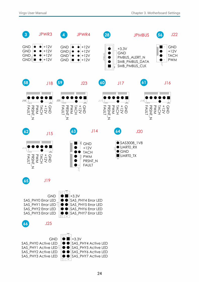
Connectors Location3 Power Supply JPWR34 Power Supply JPWR4
28 PMBUS JPMBUS56 CPU0 FAN CONN J2258 FAN1A CONN J1859 FAN1B CONN J2360 FAN2A CONN J1761 FAN2B CONN J1662 FAN3A CONN J1563 FAN3B CONN J1464 SAS IOC UART J20
65 SAS IOC ACTIVITY LED J19
66 SAS IOC ERROR LED J2543
28
56
58 59 60
62
63
64
65 66
61
24
Chapter 3. Motherboard SettingsVirgo User Manual
SAS3008_1V8UART0_RXGNDUART0_TX
J20
+12V+12V+12V+12V
GNDGNDGNDGND
JPWR4
GND+12VTACHPWM
J22
+3.3VSAS_PHY4 Error LEDSAS_PHY5 Error LEDSAS_PHY6 Error LEDSAS_PHY7 Error LED
GNDSAS_PHY0 Error LEDSAS_PHY1 Error LEDSAS_PHY2 Error LEDSAS_PHY3 Error LED
J19
+3.3VSAS_PHY4 Active LEDSAS_PHY5 Active LEDSAS_PHY6 Active LEDSAS_PHY7 Active LED
GNDSAS_PHY0 Active LEDSAS_PHY1 Active LEDSAS_PHY2 Active LEDSAS_PHY3 Active LED
J25
J23
GN
D+12VTA
CH
PWM
PRSNT_N
FAULT
J23
GN
D+12VTA
CH
PWM
PRSNT_N
FAULT
J17
GN
D+12VTA
CH
PWM
PRSNT_N
FAULT
J16
GN
D+12VTA
CH
PWM
PRSNT_N
FAULT
J15
GND+12VTACHPWMPRSNT_NFAULT
J14
59 60 61
62 64
66
4
63
56
65
+12V+12V+12V+12V
GNDGNDGNDGND
JPWR33
+3.3VGNDPMBUS_ALERT_NSMB_PMBUS_DATASMB_PMBUS_CLK
JPMBUS28
GN
D+12VTA
CH
PWM
PRSNT_N
FAULT
J18
J1858

25
Chapter 3. Motherboard SettingsVirgo User Manual
Connectors Location1 Power Supply JPWR12 Power Supply JPWR25 Power Supply JPWR5
10 VGA JVGA_INT11 COM1 JCOM1
45a45b45c
External Thermal Sensor J2、J13、J24
55 CPU1 FAN CONN J1
CPU 1CPU 1
1 2
5
10
11
45 c
55
HM_TD3+HM_TD3-
J24
GND+12VTACHPWM
J1
DSR
RTSC
TSRIN
C
DC
DRXDTXDD
TRG
ND
JCOM111 5545 c
+12V+12V+12V+12V
GN
DG
ND
GN
DG
ND
JPWR1
GN
D+5V+5V+5VN
CG
ND
GN
DG
ND
PS_ON
#G
ND
-12V+3.3V
+3.3V+12V+12V
+5V_A
UXPO
WER O
KG
ND
+5VG
ND
+5VG
ND
+3.3V+3.3V
JPWR21 2
GND+12V
GND+12V
JPWR55
DVO_5VGNDDDC_DATAOAVSYNCOAHSYNCODDC_CLKO
GNDDACROA
GNDDACGOA
GNDDACBOA
JVGA_INT10
26
Chapter 3. Motherboard SettingsVirgo User Manual
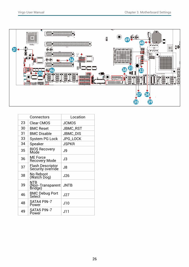
Connectors Location23 Clear CMOS JCMOS30 BMC Reset JBMC_RST31 BMC Disable JBMC_DIS33 System PG Lock JPG_LOCK34 Speaker JSPKR
35 BIOS Recovery Mode J9
36 ME Force Recovery Mode J3
37 Flash Descriptor Security override J8
38 No Reboot(Watch Dog) J26
39NTB(Non-Transparent Bridge)
JNTB
46 BMC Debug Port Select J27
48 SATA4 PIN-7 Power J10
49 SATA5 PIN-7 Power J11
a
31
3046 38 23 33
39
3437
35
4849
36

27
Chapter 3. Motherboard SettingsVirgo User Manual
CMos SettingPin1-2 Normal DefaultPin3-4 Clear CMOS
23
JBMC_RST SettingShort Reset BMCOpen Normal Defualt
JBMC_RST30
JBMC_DIS SettingShort DisableOpen Normal Defualt
JBMC_DIS31
JPG_LOCK SettingShort LockOpen Normal Defualt
JPG_LOCK33 JSPKR34 J935
J9 Setting
Short BIOS Recovery mode
Open Normal Defualt
J336
J3 SettingShort ME Recovery ModeOpen Normal Defualt
J837
J8 SettingShort Flash Security overrideOpen Normal Defualt
J26
(No reboot)
Setting
Short Enable DefaultOpen Disable
J2638
39 JNTB
J8 SettingShort Downstream portOpen Upstream port Defualt
J2746
J27
(BMC Debug Port)Setting
Short JCOMOpen JBMC_DP Defualt
J1048
J10 SettingShort SATA 4 PIN-7 PowerOpen Normal Defualt
J1149
J11 SettingShort SATA 5 PIN-7 PowerOpen Normal Defualt

28
Chapter 3. Motherboard SettingsVirgo User Manual
3.5.1 Front Panel LED Definition
Power
Yellow The system is On.
Blinking The system is in Standby; System is off, but has AC power.
Off System has no AC power
UIDBlue UID activity detected.Off No UID activity detected.
System Fault-1Red
Critical system failure detected (processors, memory, voltage regulators, thermal events,fan failures, NMI, etc).
Off No critical failures detected.
System Fault-2Red
Critical system failure detected (processors, memory, voltage regulators, thermal events,fan failures, NMI, etc).
Off No critical failures detected.
Hard DiskGreen (Blinking) Disk activity detected.Off No disk activity detected.
NIC 1Green (Blinking) NIC1 activity detected.Off NIC is not active.
NIC 2Green (Blinking) NIC2 activity detected.Off NIC is not active.
3�5�2 Rear chassis LEDs
NIC 1 (Right Upward Triangle)
Yellow (Blinking) 1G link detected, activity detected.
NIC 1 (Left Upward Triangle)
Green (Blinking) 10G link detected, activity detected.
NIC 2 (Right Downward Triangle)
Yellow (Blinking) 1G link detected, activity detected.
NIC 2 (Left Downward Triangle)
Green (Blinking) 10G link detected, activity detected.
PHY 1 (Right) Yellow (Blinking) 100M: Yellow 10M/No connect: Off.
PHY 1 (Left)Green PHY1 activity detected.Off PHY1 is not active, LAN cable no connect.
3�5 LEDs

29
Chapter 3. Motherboard SettingsVirgo User Manual
3.5.3 Internal LEDs Definition
HEART BIT Green (Blinking) BMC activity detected.OFF BMC is not active.
SYS PG LED Green System power ready.OFF System power is not ready.
RSMRST PG LED Yellow Resume Well Reset ready.OFF Resume Well Reset is not ready.
SAS IOC STATUS LEDGreen(Blinking) PHY0-7 activity detected.OFF PHY0-7 no activity detected.
SAS IOC HEART BIT LEDGreen(Blinking) SAS IOC activity detected.OFF SAS IOC no activity detected.
SAS IOC ERROR LEDYellow SAS IOC failure detected.OFF SAS IOC no failure detected.
NIC 3 10G LED Yellow (Blinking) 10G link detected, activity detected.
NIC 3 1G LED Green (Blinking) 1G link detected, activity detected.
NIC 4 10G LED Green (Blinking) 10G link detected, activity detected.
NIC 4 1G LED Yellow (Blinking) 1G link detected, activity detected.
NGFF ACTIVITY LEDBlue(Blinking) NGFF activity detected.OFF NGFF not activity detected.
NVME Hot-Plug LED NGFF ACTIVITY LED
RSMRST PG LEDSYSTEM PG LED
UID LED
SAS IOC STATUS LED(PHY0~PHY7)
SAS IOC HEART BIT LED
SAS IOC ERROR LED
BMC Heart Bit LED
LAN3 10G/1G LEDLAN4 10G/1G LED
LAN2 1G LEDLAN1 1G LED
LAN2 10G LEDLAN1 10G LED
CPU 0CPU 1CPU 1
CPU 0

30
Chapter 3. Motherboard SettingsVirgo User Manual
This chapter demonstrates how to configure the UEFI BIOS settings in your system device. You can enter the BIOS screen during system startup.
To enter BIOS configuration settings,• Press Esc key during the Power-On-Self-Test (POST)
To enter BIOS after POST, you have to restart the system by using one of the three methods:• Press Ctrl + Alt + Delete�• Press the reset button on the system chassis. • Turn the system off and on.
NOTE The following pages provide the details of BIOS menu. Please be noticed that the BIOS menu are continually changing due to the BIOS updating. The BIOS menu provided are the most updated ones when this manual is written.
4�1 Navigation KeysThe navigation keys are listed below.
Function Key Description< >
< > < >< >
Select item.
< Enter > Select and enter sub-screen.
< + > < - > Modify selected option.
< F1 > General help.
< F2 > Previous Value.
< F3 > Optimized defaults.
< F4 > Save & Exit.
< F5> < F6 > Change values.
< F7 > Discard Change and Exit.
< F9 > Load Optimal Default for all values.
< F10 > Save changes and exit.
< F12 > Print Screen.
< Esc > Exit the current menu screen.
Chapter 4. BIOS Configuration Settings

31
Chapter 3. Motherboard SettingsVirgo User Manual
4�2�1 Menu
Press and to select the options of the menu bar. Press Enter to access the option screen.
Menu Description
Main Displays basic system information and date & time.
Advanced Allows configuration of advanced system settings.
Security Sets passwords and security functions.
Power Sets the power management parameters.
Boot Sets boot options, such as Quick Boot or USB Boot.
4�2�2 Startup
Step 1 Press ESC to run the BIOS setup procedure.
CAUTIONWhen Quiet Boot is enables, OEM logo will be displayed instead of post messages.
4�2 BIOS Setup

32
Chapter 4. BIOS Configuration SettingsVirgo User Manual
Step 2 There will be a message “Entering SETUP” displayed on the diagnostics screen.
Step 3 Identify the BIOS version.
CAUTIONFor the official released version, the last digit of the BIOS version must end in a “0.“

33
Chapter 4. BIOS Configuration SettingsVirgo User Manual
Step 4 Load Optimal Default Setting.
Step 5 Save the setting and exit the BIOS setup utility.

34
Chapter 4. BIOS Configuration SettingsVirgo User Manual
4�2�3 UpdateTo identify the latest BIOS version, please check the BIOS setup.

35
Chapter 4. BIOS Configuration SettingsVirgo User Manual
Update BIOS by INSYDE H2OFFT-D utility under DOS environmentIf you need to update Flash in the DOS environment, please use H2OFFT-D utility. To use this utility, you must include the flash.bat , H2OFFT-D.exe, and bin file in the same folder. Please follow the instructions to update flash:
Step 1 Execute flash.bat to update Flash in the DOS environment.
Step 2 Reboot the system.

36
Chapter 4. BIOS Configuration SettingsVirgo User Manual
Main Option Key:
4�3�1 Main
Option Key DescriptionSystem time Configures the current time.System date Configures the current date.
4�3 Main

37
Chapter 4. BIOS Configuration SettingsVirgo User Manual
Advanced Option Key:
4.4.1 Peripheral Configuration
Peripheral Configuration
PCIe SR-IOV Enable Disable
PCIe ARI Enable DisableARI Forward Enable DisableSpread Spectrum Enable Disable
Redfish On/Off Enable Disable
4.4.2 Video Configuration
Video Configuration
Display Mode Plug In First On Board First
4.4.3 Socket Configuration
Socket Configuration
Processor Configuration
Hyper-Threading [ALL] Enable Disable
VMX Enable DisableEnable SMX Enable Disable
4�4 Advanced

38
Chapter 4. BIOS Configuration SettingsVirgo User Manual
Processor Configuration
MSR Lock Control Enable Disable
Extended APIC Enable Disable
Common RefCode Configuration
MMCFG Size64M 128M 256M
512M 1G 2G
MMIO High Base56T 40T 24T16T 4T 1T
MMIO High Granularity Size
1G 4G 16G64G 256G 1024G
Serial Debug Message Level
Disable MinimumNormal Maximum
UPI Configuration UPI Status
Link Speed Mode Slow Fast
Link Frequency Select
9.6Gb/s 10.4Gb/s
Auto Use Per Link Setting
Link L0p EnableAutoEnableDisable
Link L1 EnableAutoEnableDisable
Legacy VGA Socket Min=0, Max=3Legacy VGA Stack Min=0, Max=6
Memory Configuration
Enforce POR Auto POR Disable
Memory Frequency Selections in MHzIMC BCLK Auto 100 MHz 133 MHzMRC Promote Warnings Enable Disable
Promote Warnings Enable DisableHalt on mem Training Error Enable Disable
Write Preamble TCLK Auto 1TCLK 2TCLKRead Preamble TCLK Auto 1TCLK 2TCLKEnable ADR Enable DisableLegacy ADR Mode Enable Disable
ADR Data Save Mode Disable Batterybacked DIMMs NVDIMMs
Check PCH_PM_STS Enable Disable

39
Chapter 4. BIOS Configuration SettingsVirgo User Manual
Memory Configuration
Check Platform Detect ADR Enable Disable
Erase-Arm NVDIMMs Enable Disable
Restore NVDIMMs Enable Disable
Interleave NVDIMMs Enable Disable
Custom Refresh Rate Min=0, Max=40
SMB Clock FrequencyAuto 100 KHz400 KHz 1 MHz
IIO Configuration
PCI 64-Bit Resource Allocation Enable Disable
PCIe Train by BIOS No Yes
PCIe Hot PlugAuto ManualEnable Disable
PCIe ACPI Hot Plug Enable Disable Per-PortMC BaseAddress Range Auto Below 4G
MC Index Position 12 20MC Num Group 1 8 32 64PCI-E Completion Timeout (Global) Disable
No Yes Per-Port
PCI-E Global Timeout Value
Program the Completion Timeout Value (D:x F:0 O:B8h B:3-0) where x is 0-3
PCI-E ASPM Support (Global) L1 Only Disable Per-Port
Advanced Power Configuration
CPU State Control
WFR Uncore GV Rate Reduction
AutoEnableDisable
Uncore Freq Scaling (UFS) Enable Disable
SpeedStep (Pstates) Enable Disable
Config TDPNominalLevel 1Level 2
P State Domain All One
EIST PSD Function
HW_ALLSW_ALLSW_ANY
SINGLE_PCTL Enable Disable

40
Chapter 4. BIOS Configuration SettingsVirgo User Manual
Advanced Power Management Configuration
CPU P State Control
Single Power Domain (SPD) Enable Disable
Boot performance mode
Max Performance
Max EfficientSet by Intel Node Manager
Energy Efficient Turbo Enable Disable
Turbo Mode Enable DisableCPU Flex Ratio Override Enable Disable
Hardware PM State Control
Hardware P-States
Disable Native Mode
Out of Band Mode
Native Mode with No Legacy Support
HardwarePM Interrupt Enable Disable
EPP Enable Enable Disable
EPP profilePerformance Balanced
PerformanceBalanced Power Power
APS rocketing Enable DisableScalability Enable DisablePPO-Budget Enable Disable
Package C State Control
Package C State
C0/C1 state, state C2 state
C6(non Retention)
C6(Retention) state
No Limit AutoC2C3TT Min=0, Max=255PKG C-state Lat. Neg. Enable Disable
LTR IIO Input Take IIO LTR input.
Ignore IIO LTR input.

41
Chapter 4. BIOS Configuration SettingsVirgo User Manual
4.4.4 PCH Configuration
PCH Configuration
PCH Devices PCH state after G3 S0 S5 Last State
PCH SATA Configuration
SATA ControllerConfigure SATA as AHCI RAIDSupport Aggressive Link Power Management
Enable Disable
Alternate Device ID on RAID Enable Disable
Load EFI Driver for RAID Enable Disable
Port 0 Enable Disable
SATA Port 0 DevSlp Enable Disable
Hot Plug Enable Disable
Configure as eSATA Enable DisableMechanical Presence Switch Enable Disable
Spin Up Device Enable Disable
SATA Device Type Hard Disk Drive Sata State Drive
SATA TopologyUnknown ISATA Direct Connect
Flex M.2
Port 1 Enable Disable
SATA Port 1 DevSlp Enable Disable
Hot Plug Enable Disable
Configure as eSATA Enable Disable
SATA HDD Unlock Enable Disable
SATA Led locate Enable Disable
RAID 0 Enable Disable
RAID 1 Enable Disable
RAID 10 Enable Disable
RAID 5 Enable DisableIntel Rapid Recovery Technology Enable Disable
RAID Option ROM UI banner Enable Disable
IRRT Only on ESATA Enable Disable

42
Chapter 4. BIOS Configuration SettingsVirgo User Manual
PCH SATA Configuration
Smart Response Technology Enable Disable
RAID OROM prompt delay
2 Seconds 4 Seconds6 Seconds 8 Seconds
PCH sSATA Configuration
sSATA Controller Enable DisableConfigure sSATA as AHCI RAIDSupport Aggressive Link Power Management
Enable Disable
Alternate Device ID on RAID Enable Disable
Load EFI Driver for RAID Enable Disable
Port 0 Enable DisableHot Plug Enable DisableConfigure as eSATA Enable DisableSpin Up Device Enable DisablesSATA Device Type Hard Disk Drive Sata State Drive
SATA TopologyUnknown ISATA Direct ConnectFlex M.2
Port 1 Enable DisableHot Plug Enable DisableConfigure as eSATA Enable DisableSATA HDD Unlock Enable DisableSATA Led locate Enable DisableRAID 0 Enable DisableRAID 1 Enable DisableRAID 10 Enable DisableRAID 5 Enable DisableIntel Rapid Recovery Technology Enable Disable
RAID Option ROM UI banner Enable Disable
IRRT Only on ESATA Enable DisableSmart Response Technology Enable Disable
RAID OROM prompt delay
2 Seconds 4 Seconds6 Seconds 8 Seconds
PCH Internal LAN Enable DisableWake on LAN Enable Disable
43
Chapter 4. BIOS Configuration SettingsVirgo User Manual
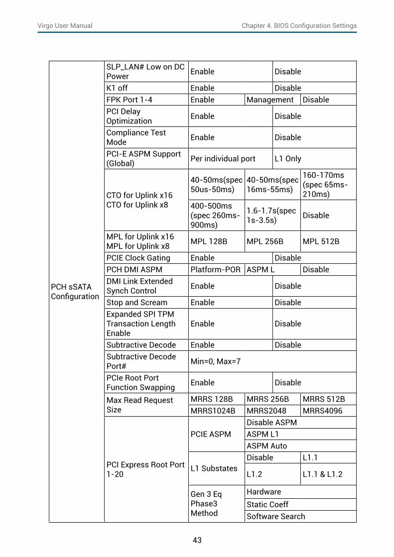
PCH sSATA Configuration
SLP_LAN# Low on DC Power Enable Disable
K1 off Enable DisableFPK Port 1-4 Enable Management DisablePCI Delay Optimization Enable Disable
Compliance Test Mode Enable Disable
PCI-E ASPM Support (Global) Per individual port L1 Only
CTO for Uplink x16CTO for Uplink x8
40-50ms(spec 50us-50ms)
40-50ms(spec 16ms-55ms)
160-170ms(spec 65ms-210ms)
400-500ms(spec 260ms-900ms)
1.6-1.7s(spec 1s-3.5s) Disable
MPL for Uplink x16MPL for Uplink x8 MPL 128B MPL 256B MPL 512B
PCIE Clock Gating Enable DisablePCH DMI ASPM Platform-POR ASPM L DisableDMI Link Extended Synch Control Enable Disable
Stop and Scream Enable DisableExpanded SPI TPM Transaction Length Enable
Enable Disable
Subtractive Decode Enable DisableSubtractive Decode Port# Min=0, Max=7
PCIe Root Port Function Swapping Enable Disable
Max Read Request Size
MRRS 128B MRRS 256B MRRS 512BMRRS1024B MRRS2048 MRRS4096
PCI Express Root Port 1-20
PCIE ASPMDisable ASPMASPM L1ASPM Auto
L1 SubstatesDisable L1.1
L1.2 L1.1 & L1.2
Gen 3 Eq Phase3 Method
HardwareStatic CoeffSoftware Search

44
Chapter 4. BIOS Configuration SettingsVirgo User Manual
PCH sSATA Configuration
PCI Express Root Port 1-20
ACS Enable DisableURR Enable DisableFER Enable DisableNFER Enable DisableCER Enable DisableSEFE Enable DisableSENFE Enable DisableSECE Enable DisablePME SCI Enable DisableHot Plug Enable DisableAdvanced Error Reporting
Enable Disable
PCIe SpeedAuto Gen 1Gen 2 Gen 3
MSI Enable Disable
PCIE Lane Topology
Unknown x1x4 Sata ExpressM.2
Max Payload Size
MPLMPL 128BMPL 256B
Compl. Timeout
40-50ms(spec 50us-50ms)
40-50ms(spec 16ms-55ms)
160-170ms(spec 65ms-210ms)
400-500ms(spec 260ms-900ms)
1.6-1.7s(spec 1s-3.5s) Disable
PCH PCIe LTR Configuration
PCH PCIE1 LTR Enable Disable
Snoop Latency Override
AutoManualDisable
Snoop Latency Value Min=0, Max=1023
Snoop Latency Multiplier
1 ns 32 ns1024 ns 32768 ns1048576 ns 33554432 ns

45
Chapter 4. BIOS Configuration SettingsVirgo User Manual
PCH sSATA Configuration
PCH PCIe LTR Configuration
Non Snoop Latency Override
AutoManualDisable
Non Snoop Latency Value Min=0, Max=102
Non Snoop Latency Multiplier
1 ns 32 ns1024 ns 32768 ns1048576 ns 33554432 ns
PCIE1 LTR Lock Enable Disable
4.4.5 H2o IPMI Configuration
H2o IPMI Configuration
IPMI Support Enable Disable
BMC Warmup Time Min=0, Max=240
ACPI SPMI Table Enable Disable
Boot Option Support Enable Disable
Set BIOS version to BMC
Enable Disable
BMC Configuration
Watchdog Timer Support Enable Disable
Not disable in OS Enable DisableWatchdog Timer Timeout Min=2, Max=8
Watchdog Timer Action
No Action Hard ResetPower Down Power Cycle
Power Cycle Time Support Enable Disable
Power Cycle Time Min=0, Max=255Power Button Enable DisableReset Button Enable DisableNMI Button Enable DisableLAN Channel Number Min=0, Max=15IPv4 Source Static DHCPIPv6 Mode Enable DisableIPv6 Prefix Length Min=0, Max=15
SDR List SDR List Support Enable Disable

46
Chapter 4. BIOS Configuration SettingsVirgo User Manual
4.4.6 H2o Event Log Config Manager
H2o Event Log Config Manager
ConfigurationsPage
Console Serial Redirect Enable Disable
Terminal TypeVT_100 VT_100+VT_UTF8 PC_ANSI
Baud Rate
1200 24004800 960019200 3840057600 115200
Data Bits 7 Bits 8 BitsParity None Even OddStop Bits 1 Bits 2 BitsFlow Control None RTS/CTS XON/XOFF
Information Wait Time0 Second 2 Seconds 5 Seconds10 Seconds 30 Seconds
C.R. After Legacy Boot No Yes
Text Mode ResolutionAUTO
Force 80x25,Force 80x24 (DEL FIRST ROW)
Force 80x24 (DEL LAST ROW) Limit 128x40
Auto Refresh Enable DisableAuto adjust Terminal resolution Enable Disable

47
Chapter 4. BIOS Configuration SettingsVirgo User Manual
Security Option Key:
4�5�1 Security
SecurityCurrent TPM Device Not Detected TPM 1.2 TPM 2.0
TrEE Protocol Version 1.0 1.1
TPM Availability Available Hidden
TPM Operation No operation Disable and Deactivate Enable and Activate
4�5 Security

48
Chapter 4. BIOS Configuration SettingsVirgo User Manual
Power Option Key:
4�6�1 Power
PowerWake on PME Enable Disable
4�6 Power

49
Chapter 4. BIOS Configuration SettingsVirgo User Manual
Boot Option Key:
4�7�1 Boot
BootBoot Type Dual Boot Type Legacy Boot Type UEFI Boot TypeQuick Boot Enable DisableQuiet Boot Enable DisableNetwork Stack Enable DisablePXE Boot to LAN Enable Disable
PXE Boot capability
Disable UEFI:IPv4 UEFI:IPv6UEFI:IPv4/UEFI:IPv6 Legacy
Add Boot Options First Last Auto
ACPI Selection
Acpi1.0B Acpi3.0 Acpi4.0Acpi5.0 Acpi6.0 Acpi6.1
USB Boot Enable DisableEFI Device First Enable Disable
Timeout Min=0, Max=10Automatic Failover Enable Disable
4�7 Boot

50
Chapter 4. BIOS Configuration SettingsVirgo User Manual
Exit Option Key:
4�8�1 Exit
Save and ExitExit Saving Changes Exit system setup and save your changes.Save Change Without Exit Save your changes without exiting the system.
Exit Discarding Changes Discard your changes when existing the system.
Load Optimal Defaults Load optimal default items.
Load Custom Defaults
Resets the BIOS settings to the default values and overwrites any previously customized settings.
Save Custom Defaults Saves the cumostomized defaults in BIOS settings.
Discard Changes Discard your changes.
4�8 Exit

51
Chapter 5. BMC Configuration SettingsVirgo User Manual
Insert Ethernet LAN cable into the BMC LAN port. There are two methods to setup BMC IP:
5�1 Method 1 (Use the BIOS Setup)Step 1 BIOS SETUP Advanced H2O IPMI configuration BMC Configuration
IPv4 source Static
BMC management port(Dedicated NIC channel 1 )
Spica User ManualChapter 5. BMC Configuration Settings

52
Chapter 5. BMC Configuration SettingsVirgo User Manual
Step 2 Input the IP address. Set static IP.

53
Chapter 5. BMC Configuration SettingsVirgo User Manual
Step 3 Input the subnet mask address.

54
Chapter 5. BMC Configuration SettingsVirgo User Manual
Step 1 Type in "sc –lanset."
Step 2 Modify the IP setting.
NOTEType 1 for selecting static IP Mode or Type 2 for selecting DHCP Mode.
Step 3 Input the IP address.
5�2 Method 2 (Use a Dos Tool - Syscheck)
55
Chapter 5. BMC Configuration SettingsVirgo User Manual
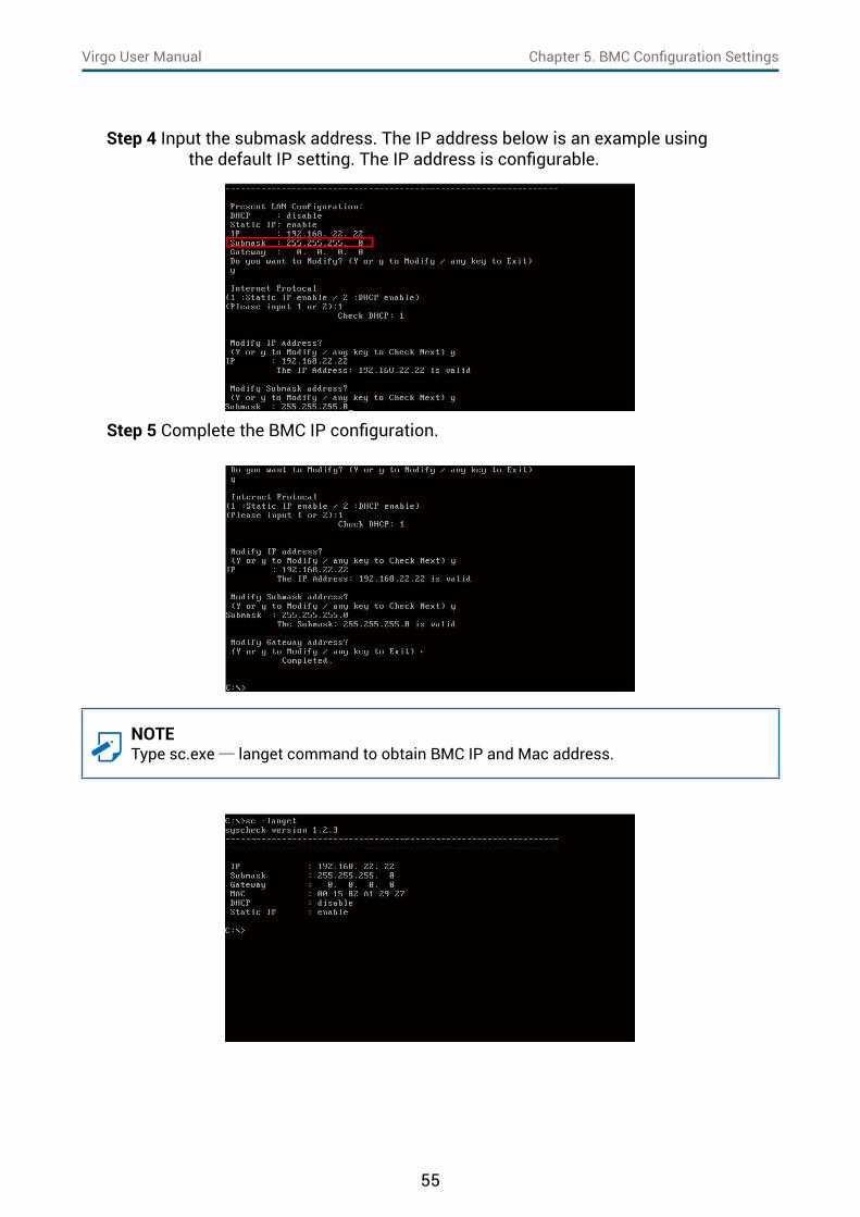
NOTEType sc.exe─ langet command to obtain BMC IP and Mac address.
Step 4 Input the submask address. The IP address below is an example using the default IP setting. The IP address is configurable.
Step 5 Complete the BMC IP configuration.
56
Chapter 5. BMC Configuration SettingsVirgo User Manual
NOTEThis feature works with JAVA 6 Runtime installed Console Environment.
The IP address below is an example using the default IP setting. The IP address is configurable.
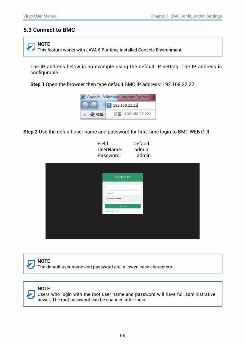
Step 1 Open the browser then type default BMC IP address: 192.168.22.22
Step 2 Use the default user name and password for first-time login to BMC WEB GUI.
Field: Default UserName: admin Password: admin
NOTEThe default user name and password are in lower-case characters.
NOTEUsers who login with the root user name and password will have full administrative power. The root password can be changed after login.
5�3 Connect to BMC
57
Chapter 5. BMC Configuration SettingsVirgo User Manual
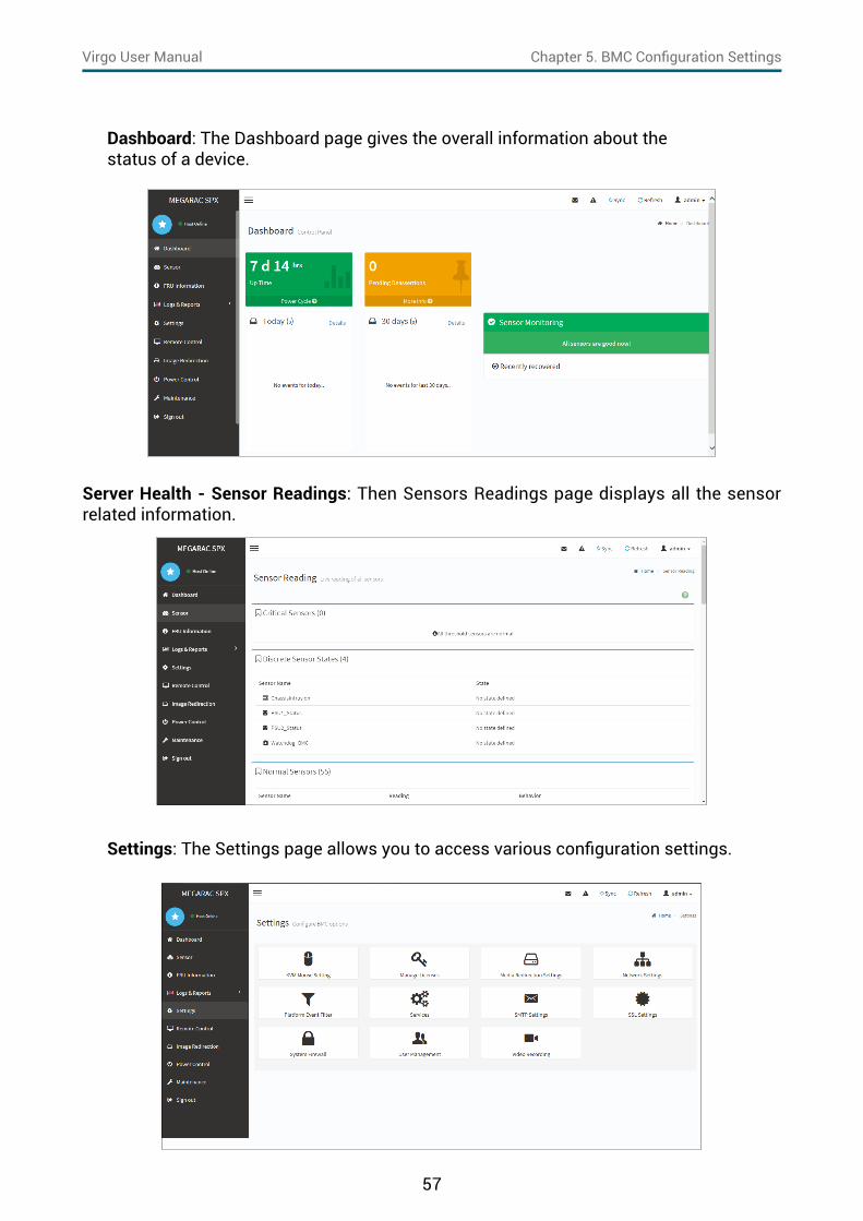
Dashboard: The Dashboard page gives the overall information about thestatus of a device.
Server Health - Sensor Readings: Then Sensors Readings page displays all the sensor related information.
Settings: The Settings page allows you to access various configuration settings.

58
Chapter 5. BMC Configuration SettingsVirgo User Manual
KVM Mouse Setting: The KVM Mouse Setting page displays the setting for mouse emulation from local window to remote screen.
• For Windows OS environment, set mode to absolute.• For Linux OS environment, set mode to relative.• For SLES-11 OS environment, set mode to other mode.
Remote Control: The Remote Control page allow you to access any of the managed devices within your system.

59
Chapter 5. BMC Configuration SettingsVirgo User Manual
Environmental setting:

60
Chapter 5. BMC Configuration SettingsVirgo User Manual
5�4 Updating BMC Firmware
Step 1 Boot to the DOS (MS-DOS or Free DOS is workable).Step 2 Enter BMC firmware directory [XXXXXZYY]; XXXXX: project name ; YY: firmware version; Z: Identify character, C for official, B for Beta.Step 3 Execute a�bat batch file to update the BMC firmware Example: A:>cd SB301C01 A:\ SB301C01>a.bat This is just an example. The latest BMC firmware version is available from the FAE or AIC website.Step 4 After updating the BMC firmware, please turn off and restart the Example: system.
NOTE1. Do not use EMM386 in Dos environment when updating the firmware or you will
receive a system failure.2. In some critical conditions, after updating the BMC firmware or config file, you might
need to unplug the AC power cord for 5 seconds and then plug in the AC power cord to reset the BMC for the updated new function to work properly.

Chapter 6� Technical Support
Taiwain, Global HeadquartersAddress: No� 152, Section 4, Linghang N� Rd, Dayuan District, Taoyuan City 337, TaiwanTel: +886-3-433-9188Fax: +886-3-287-1818Sales Email: sales@aicipc�com�twSupport Email: support@aicipc�com
Shanghai, ChinaAddress: Room 1009, No� 777, Zhaojia Bang Rd, Shanghai 200032,Shanghai, ChinaTel: +86-21-54961421Fax +86-21-54961422 #608Sales Email: csales@aicipc�com�twSupport Email: support@aicipc�com
Tokyo, JapanAddress: Level 21 Shiodome Shibarikyu Building 1-2-3 Kaigan Minato-ku Tokyo 105-0022 JapanTel: +81-3-5403-6325Sales Email: [email protected] Email: support@aicipc�com
Moscow, RussiaAddress: Khoroshevskoye Shosse, 32A, Office 403 (2nd Entrance, 4th Floor), Moscow 123007, RussiaTel: +7-4997019998Sales Email: support-ru@aicipc�com�twSupport Email: support-ru@aicipc�com�tw
North California, United StatesAddress: 48531 Warm SpringsBoulvard Suite 404 Fremont, CA 94539, United StatesTel: +1-510-573-6730Fax: +1-510-573-6729Sales Email: sales@aicipc�comSupport Email: support@aicipc�com
South California, United StatesAddress: 21808 Garcia LaneCity of Industry, CA 91789, United StatesToll free: +7-4997019998Tel: +1-909-895-8989Fax: +1-909-895-8989#157Sales Email: sales@aicipc�comSupport Email: support@aicipc�com
New Jersey, United StatesAddress: 11 Melanie Lane Unit #20 & 21 East Hanover, NJ 07936, United StatesTel: +1-973-884-8886Fax: +1-973-884-4794Sales Email: sales@aicipc�comSupport Email: support@aicipc�com
Houten, The NetherlandsAddress: Peppelkade 58, 3992AK, Houten, The NetherlandsTel: +31-30-6386789Fax: +31-30-6360638Sales Email: sales@aicipc�nlSupport Email: support@aicipc�com