boatowner's illustrated electrical handbook - jimster.nets illustrated... · boatowner’s...
TRANSCRIPT


Boatowner’s Illustrated Electrical Handbook
Second Edition
Charlie Wing
International Marine / McGraw-Hill
Camden, Maine • New York • Chicago • San FranciscoLisbon • London • Madrid • Mexico City • MilanNew Delhi • San Juan • Seoul • Singapore • Sydney • Toronto

Copyright © 1993, 2006 by Charlie Wing. All rights reserved. Manufactured in the United States of America. Except as permitted under the United StatesCopyright Act of 1976, no part of this publication may be reproduced or distributed in any form or by any means, or stored in a database or retrieval system, with-out the prior written permission of the publisher.
0-07-148693-3
The material in this eBook also appears in the print version of this title: 0-07-144644-3.
All trademarks are trademarks of their respective owners. Rather than put a trademark symbol after every occurrence of a trademarked name, we use names in aneditorial fashion only, and to the benefit of the trademark owner, with no intention of infringement of the trademark. Where such designations appear in this book,they have been printed with initial caps.
McGraw-Hill eBooks are available at special quantity discounts to use as premiums and sales promotions, or for use in corporate training programs. For moreinformation, please contact George Hoare, Special Sales, at [email protected] or (212) 904-4069.
TERMS OF USE
This is a copyrighted work and The McGraw-Hill Companies, Inc. (“McGraw-Hill”) and its licensors reserve all rights in and to the work. Use of this work is sub-ject to these terms. Except as permitted under the Copyright Act of 1976 and the right to store and retrieve one copy of the work, you may not decompile, disas-semble, reverse engineer, reproduce, modify, create derivative works based upon, transmit, distribute, disseminate, sell, publish or sublicense the work or any partof it without McGraw-Hill’s prior consent. You may use the work for your own noncommercial and personal use; any other use of the work is strictly prohibited.Your right to use the work may be terminated if you fail to comply with these terms.
THE WORK IS PROVIDED “AS IS.” McGRAW-HILL AND ITS LICENSORS MAKE NO GUARANTEES OR WARRANTIES AS TO THE ACCURACY,ADEQUACY OR COMPLETENESS OF OR RESULTS TO BE OBTAINED FROM USING THE WORK, INCLUDING ANY INFORMTION THAT CAN BEACCESSED THROUGH THE WORK VIA HYPERLINK OR OTHERWISE, AND EXPRESSLY DISCLAIM ANY WARRANTY, EXPRESS OR IMPLIED,INCLUDING BUT NOT LIMITED TO IMPLIED WARRANTIES OF MERCHANTABILITY OR FITNESS FOR A PARTICULAR PURPOSE. McGraw-Hilland its licensors do not warrant or guarantee that the functions contained in the work will meet your requirements or that its operation will be uninterrupted orerror free. Neither McGraw-Hill nor its licensors shall be liable to you or anyone else for any inaccuracy, error or omission, regardless of cause, in the work or forany damages resulting therefrom. McGraw-Hill has no responsibility for the content of any information accessed through the work. Under no circumstances shallMcGraw-Hill and/or its licensors be liable for any indirect, incidental, special, punitive, consequential or similar damages that result from the use of or inabilityto use the work, even if any of them has been advised of the possibility of such damages. This limitation of liability shall apply to any claim or cause whatsoeverwhether such claim or cause arises in contract, tort or otherwise.
DOI: 10.1036/0071446443

We hope you enjoy thisMcGraw-Hill eBook! If
you’d like more information about this book,its author, or related books and websites,please click here.
Professional
Want to learn more?

ContentsForeword by Ed Sherman v
Introduction 1
1. Basic DC Circuits 2
What Electricity Is • Ohm’s Law • Loads • Sources • Practice Problems
2. DC Measurements 14
Analog Test Instruments • Digital Test Instruments • Digital vs. Analog Test Instruments • Homemade Testers • Troubleshooting
3. Batteries 26
What Is a Battery? • A Few Messy Details • Electrical Model of Batteries • MonitoringBattery Health • Discharge Characteristics • Charging Characteristics • Charging Recommendations • Estimating Your Daily Load • Choosing a Battery Type • Optimum Depth of Discharge • Sizing the Alternator • Series vs. Parallel • BatteryBoxes • ABYC Standards for Batteries
4. Alternators 48
A Galley Alternator • A Rotary Current Machine • Rectification • Controlling the Alternator • Type-P and Type-N Alternators • Powering the Voltage Regulator • Regulator Bypass Controls • Link 2000-R Charge Controller • Charging Setups • Alternator Installation • Troubleshooting
5. Bonding 70
What Is Bonding? • Lightning Protection • Corrosion Protection • Stray-Current Protection • To Bond or Not to Bond • Sizing the Anode(s) • Testing Your Protection • Noncathodic Corrosion • The ABYC on Cathodic Protection
6. DC Standards and Practices 92
Wiring Diagrams • Marine Wire • ABYC DC Load Calculation • Allowable ConductorAmperage • Allowable Voltage Drop • Identification and Installation • Overcurrent Protection • Conductor Connections • Ignition Protection
7. AC Basics 114
Alternating Current • Power Factor • AC Safety • Grounding • Conductor Identification • Transformers • AC Measurements • Troubleshooting AC Circuits • Checking Polarity
8. Inverters and Generators 128
Why Have AC Power? • Figuring Your AC Budget • Inverters • Transfer Switching • Generators • Toubleshooting Generators
For more information about this title, click here

9. AC Standards and Practices 144
Shore Power • Generator and Inverter Sources • Main Panelboard • AC Load Calculations • Overcurrent Protection • Approved Wire and Cable • Ampacity Tables • Conductor Installation • The Green Wire • Approved Shore-Power Circuits
10. Conservation for Liveaboards 182
Costs per Kilowatt-Hour • Lighting Savings • Refrigeration Savings • Other Savings
11. Solar Power 194
Is Solar for You? • How Photovoltaics Work • Photovoltaic Panels • Interpreting Specifications • Panel Orientation • Estimating Output • Mechanical Installation • Electrical Installation • Rules for Solar Success
12. Wind Power 208
Is Wind Power for You? • Getting Power from the Wind • How Much Wind Is There? • Estimating Daily Output • Specifications • Electrical Installation • Mechanical Installation • Water Generators
13. Installing Electronics 222
Antennas • Antenna Cable and Connectors • Moisture Protection • VHF Radio • GPS and SSB • Radar • Receiver/Transmitter Installation • Harnessing Electrical Noise• Electrical Filters
14. Do-It-Yourself Projects 238
Passive Circuit Components • Active Circuit Components • Projects
Appendices 258
Other Wiring Standards • English/Metric Conversions • Temperature Conversions • Power Conversions • Resistance of Copper Wire • Losses in Coaxial Cables • WiringColor Codes • Useful Electrical Formulas • Identifying Resistors • Identifying Capacitors • Trigonometric Tables
Glossary 270
Index 276

v
Since I have used Charlie Wing’s first edition of the Boatowner’s Illustrated Electrical Handbook as a text forsome of my electrical courses over the years, I am quitefamiliar with its contents. I’ve just finished reviewingthe second edition and can say without reservation thatit is more than just an update. The diagrams are dra-matically improved and the topics covered are reallycomprehensive, just what’s needed in today’s world ofever increasing complexity on newer boats.
This second edition is perfect for learning how yourboat’s electrical system and much of its equipmentworks, and it will be an invaluable guide when addingequipment as well. Further, Charlie Wing has remainedfaithful to the recommendation and application of thestandards for installation and equipment as set forth by
the American Boat and Yacht Council (ABYC). As thesenior technical instructor for the ABYC and its cur-riculum designer I really appreciate the effort through-out the book to advise the reader on how to makerepairs and modifications to his or her boat and remaincompliant with the most recognized design and repairstandards for recreational boats in the world. We at theABYC know full well that adherence to these standardsmake a better, safer boat.
I have already begun recommending this secondedition to my students and seminar participants, andwill continue to do so. This book needs to be in everyboater’s library as a ready reference on how to makeeffective repairs and modifications that comply withABYC standards.
Ed ShermanABYC Senior Instructor and Curriculum Designer
Foreword
Copyright © 1993, 2006 by Charlie Wing. Click here for terms of use.

This page intentionally left blank

1
Many of us have, at the least, a passing familiarity withelectrical wiring. When a switch or receptacle in ourhome fails, we replace it. Some of us feel secure inextending a circuit, adding a new circuit, even wiringan entire house. We are able to do so because of theNational Electric Code (NEC) and because many excel-lent books, based on the NEC, have been written forboth the novice and the professional.
Unfortunately, a boat is not a house—a fact that stillescapes all too many boatyards.
I’ll never forget the time I was working in a boat-yard rigging masts. I had spent an hour trying to deter-mine why a mast-top anchor light was not working.The blue anchor-light supply conductor disappearedinto the base of the 60-foot mast, yet no blue conductorappeared at the other end. I commented on the mysteryto a co-worker who I knew had worked as an electricianat one the country’s premier boatbuilders.
“Sure,” he said. “We’d grab a spool of #14 whatever,and when that ran out, we just spliced in another. Thecolor of the wire doesn’t matter.”
Or ask a random sampling of boatbuilders whetherbronze through-hulls should be bonded. Chances aregood you will get an even split of opinions. No won-der boatowners are confused!
In fact, there is a voluntary standard for the con-struction and repair of boats, including the topics ofAC and DC wiring, lightning protection, and bondingfor corrosion control. It is the American Boat and YachtCouncil (ABYC) Standards for Small Craft. The stan-dards are the marine equivalent of the residentialNational Building Code and National Electric Code.
Twelve years ago, when the first edition of this bookwas written, few boat manufacturers and fewer boat-yards paid much attention to the fledgling ABYC.Today, nearly all manufacturers and many boatyardshave joined the organization and have sent employeesto the excellent technical courses offered by the ABYC’sWestlawn Institute of Marine Technology. In the wordsof the ABYC, the standards are: “ . . . believed to rep-resent, as of the date of publication, the consensus ofknowledgeable persons, currently active in the field ofsmall craft, on performance objectives that contributeto small boat safety.”
This book is my attempt at interpretation and illu-mination of the several wiring-related ABYC standardsand much more.
My joy in life derives from explaining and illustrat-ing how things work—first as a physics teacher at Bow-doin College, then as founder of the first two owner-builder schools in the country, and later as author ofthirteen books on home building and repair and sixbooks on marine topics.
I have always felt that knowledge is of limited utilityunless based upon an understanding of the basic prin-ciples—simply put, how things work. In this book youwill find that each subject begins with a simple explo-ration and explanation of the hows and whys.
I also feel that books—even those of a technicalnature—should be fun. We boatowners have no needfor Miss Grundy to rap our knuckles to command ourattention. Discovery of how your boat works shouldbe fun and exciting. To this end you will find dozens ofsimple experiments and projects designed to make thelight in your mind come on, perhaps even add to thecomfort and convenience of your boat.
I hope you will come away from this book with thefeeling that (to paraphrase Ratty in Wind in the Wil-lows) “There is nothing half so much worth doing asmessing about in your boat’s electrical system.”
I have invented nothing. You will find here no newlaw of physics, nor any previously unreported electricalor magnetic phenomena. I have simply attempted tobring to you, the reader, a lucid and clearly illustratedaccount of how the best minds in the business think asmall boat should be wired.
To this end, in this second edition I have redrawnmany of the original illustrations, added illustrations,and added color to the ABYC-recommended wiring forAC shore-power systems. Also new is the ABYC proce-dure for testing and sizing protective zinc anodes,material on absorbed-glass mat (AGM) batteries, spe-cific recommendations for charging most marine bat-teries, descriptions of “smart” alternator regulators, andtroubleshooting charts for engine-starting and battery-charging circuits.
May your boat never corrode, your engine never failto start, and your batteries last forever!
Introduction
Copyright © 1993, 2006 by Charlie Wing. Click here for terms of use.

Basic DC Circuits
2
CHAPTER 1
Voltagesource
+
_
R
V
Load
Current, I
Copyright © 1993, 2006 by Charlie Wing. Click here for terms of use.

3
Basic to the ability to work with electricalwiring—be it residential or marine—is anunderstanding of what electricity is. You’ll find
that the discovery of electricity, as we now understandit, was fairly recent.
The key that unlocks the wiring puzzle is the con-cept of the electrical circuit. With this simple conceptand a single formula—Ohm’s Law—you can under-stand and predict the behavior of 99% of the wiring onyour boat. You will be able to deal with circuits con-taining loads in series, loads in parallel, even loads inseries/parallel combinations. Similarly, you will be ableto predict the behavior of voltage sources in series andvoltage sources in parallel. You will also discover the dif-ferences between voltage, current, energy, and power.
Finally I have provided a set of 18 practice problemson which you can cut your electrical teeth.

4 Basic DC Circuits
We live in the age of electricity. Without electricity wecouldn’t watch television, drive automobiles, makefrozen margaritas, microwave popcorn, read at night,or talk to our friends on the phone.
Many people think electricity is difficult to under-stand. They are wrong. Because you are surrounded byand unconsciously use electrical devices every day, littlelights will go on in your head as you discover the con-cepts. You’ll probably say, “Oooh—so that’s why myboat battery is dead every morning!”
I believe you will find electricity to be fun. I amabsolutely sure that, having grasped the very simpleconcepts behind boat wiring, you will feel more confi-dent both in your boat and in yourself.
Electricity consists of electrons. An electron is thesmallest quantity of electricity that exists. It is such asmall quantity, however, that we use the unit coulomb(1 coulomb = 6.24 × 10¹⁸ electrons) in calculations.
The flow of electrons is often compared to the flowof water, so it is natural that we call electron flow “elec-tric current.” The basic unit of electric current is theampere (1 ampere = 1 coulomb per second of electronsmoving past a point).
What we usually refer to as electricity is the controlof electrons for useful purposes. Our understanding ofelectron behavior allows us to predict the flow of elec-trons through electrical circuits. The instruments onyour boat contain circuits. Indeed, a boat’s wiring isno more than a collection of circuits. When we under-stand circuits, we will understand the behavior of elec-tricity on a boat.
A Circuit Electrons can be neither created nor destroyed, but canmove through conductive materials. An electric currentrequires a continuous path of electrically conductivematerial, through which the electrons can return totheir source.
If this were not so, electrons would dribble from theend of a wire like water from a leaky faucet, and bat-teries would soon sit like empty water glasses with alltheir electrons lying around them in a pool.
We call a continuous electrical path a circuit. If a cir-cuit is unbroken, we call it a closed circuit. If it is inter-rupted, preventing the flow of electricity, we say the cir-cuit is open.
All materials present a degree of resistance to elec-tron flow, but the variation is so great that some mate-
What Electricity Is
rials are termed conductors and others insulators.The best conductors are gold, silver, mercury, cop-
per, and aluminum. Copper is most often the best com-promise between cost and conductivity. The best insu-lators are glass, ceramics, mica, and plastics. Plastic isthe material most often used due to its low cost, dura-bility, and ease of manufacture.
Unfortunately for boaters, salt solutions, such asseawater, are also good conductors.
Electrical current is expressed as a rate of electronflow. In a circuit, two factors control the current (I): theelectrical driving force, or voltage (V), and the resis-tance (R) to flow of the circuit materials.
The Discovery of ElectricityDemocritus (460?–370? BC) proposes an “atomic the-ory” wherein all matter is made up of indivisible parti-cles, or atoms.
Charles de Coulomb (1736–1806) discovers that theforce of attraction between electric charges is propor-tional to the product of the two charges and inverselyproportional to the distance between them.
Luigi Galvani (1737–1798) discovers that two unlikemetals immersed in blood cause the muscles of a frog’slegs to twitch.
Alessandro Volta (1745–1827) discovers that a currentflows between two connected unlike metals in a saltsolution and, thus, invents the battery.
John Dalton (1766–1844) proposes the first table ofatomic weights of elements.
André Ampere (1775–1836) develops the theory of mag-netic lines of force and quantifies electric current forthe first time.
Hans Oersted (1777–1851) discovers a connectionbetween electric current and magnetism and a way tomeasure electric current by the deflection of a magnet.
Georg Ohm (1787–1854) discovers the relationship(Ohm’s Law) between voltage, current, and resistance ina circuit.
Michael Faraday (1791–1867) analyzes the chemicalreactions in batteries and defines the terms “electrode,”“anode,”“cathode,” and “electrolyte.”
James Clerk Maxwell (1831–1879) develops the mathe-matical equations relating electricity and magnetism.
Joseph Thomson (1856–1940) proves that electricityconsists of electrons.

5Ohm’s Law
To see just how simple electricity is, we are going toconsider the basic equation of current flow in an elec-trical circuit. With this equation you will be able tounderstand, predict, and troubleshoot more than 90%of all the electrical problems on a boat.
Question 1. Does current, I, increase or decrease as weincrease the driving force (voltage, V)?
Answer 1. Current most likely increases withincreasing voltage.
Question 2. Does current, I, increase or decrease as weincrease the resistance to electron flow (resistance, R)?
Answer 2. Current most likely decreases withincreasing resistance.
Question 3. Considering the answers to questions 1 and2, what would be the simplest and, therefore, mostlikely, relationship between current (I), voltage (V),and resistance (R)?
Answer 3. There are four possible “simplest” equa-tions:
I = V + R, I = V – R, I = V × R, and I = V/R
If you play with the values for a minute, you’ll agreethat the first three equations are unlikely. For example,if we make resistance, R, infinite, current, I, becomes ,– , , and 0. Only the last value is reasonable, so therelationship is most likely
I = V/R
Congratulations! You have just discovered Ohm’sLaw. If Georg Ohm hadn’t beaten you to it in 1827, youmight be up for a Nobel Prize.
Using Ohm’s Law This is such an important relationship, we must be pre-cise in its definition and the ways in which it can beused. First, if we wish to calculate electrical quantities,we must define the units in which these quantities aremeasured.
I = V/R where:I = amperes, abbreviated as A V = volts, abbreviated as V R = ohms, abbreviated as Ω
Let’s see how Ohm’s Law is used. Ohm’s Law appliesto all situations, but it is useful only in circuits whereelectricity is flowing.
The voltage source in Figure 1.1 is a device that pro-duces a voltage difference. Examples are batteries andpower supplies. Unless otherwise noted, assume voltagesources are batteries. The load is any device or compo-nent that consumes electrical energy and, in so doing,results in a voltage drop. Examples are resistors, lamps,and motors. Unless otherwise stated, assume loads areresistances (the zigzag symbol). For a table of electri-cal symbols used in this book, see Figure 6-1.
Example: If the load is a resistance of 2 ohms, andthe voltage source is a 12-volt battery, then by Ohm’sLaw
I = V/R = 12 V/2 Ω = 6 A
We can also rearrange Ohm’s Law so that we cancalculate either V or I, given the other two values. Thealternate forms of Ohm’s Law are:
V = I × RR = V/I
There is more good news. Ohm’s Law applies tomore complex circuits as well. We can combine loadsand sources in series (end-to-end), parallel (side-by-side), and series/parallel, and the equations remain thesimplest possible, as you will see in the figures andexamples that follow.
Ohm’s Law
Voltagesource
+
_
R
V
Load
Current, IFig. 1.1 Simple Electric Circuit

6 Basic DC Circuits
Loads in SeriesResistive loads in series act like one continuous load ofa total resistance equal to the sum of the individualresistances:
R = R1 + R2+ R3, etc.I = V/(R1 + R2+ R3, etc.)
Example:R1 = 2 Ω, R2 = 3 Ω, R3 = 5 Ω, V = 12 V R = 2 + 3 + 5 = 10 Ω
Loads in ParallelThe same voltage, V, exists across each of the loads.Ohm’s Law predicts the currents through the loads:
I1 = V/R1, I2 = V/R2, I3 = V/R3, etc.Total current, I, is the sum of currents:
I = I1 + I2 + I3, etc.= V(1/R1 + 1/R2 + 1/R3, etc.)
In other words,1/R = 1/R1 + 1/R2 + 1/R3, etc.
Loads
Example: R1 = 20 Ω, R2 = 30 Ω, R3 = 50 Ω, V =12 V.
1/R = 1/R1 + 1/R2 + 1/R3= 1/20 + 1/30 + 1/50= 0.050 + 0.033 + 0.020= 0.103
R = 1/0.103 = 9.68 Ω
I = V/R = 12 V/9.68 Ω= 1.24 A
Loads in Series/ParallelObserve that the parallel group of loads can be con-sidered a single resistor in series with other series loads.We first calculate the equivalent value of the parallelloads, as in the previous example, and then add theresult of the other series loads:
Example: RS1 = 2 Ω, RS2 = 3 Ω, RP1 = 5 Ω, RP2 =10 Ω, V = 12 V
1/RP = 1/RP1 + 1/RP2= 1/5 + 1/10= 0.20 + 0.10= 0.30
RP = 3.33 Ω
R = RS1 + RS2 + RP= 2 Ω + 3 Ω +3.33 Ω= 8.33 Ω
I = 12 V/8.33 Ω= 1.44 A
Voltagesource
+
_
R1
I
R2
R3
Total load, RV
Fig. 1.2 Series Loads
Voltagesource
+
_
R1
I
R2 R3
V
I1 I2 I3
Total load, R
Fig. 1.3 Parallel Loads
Voltagesource
+
_
I
RS2
RP1
V
RS1
RP2
Fig. 1.4 Series/Parallel Loads

7Sources
Sources in Series
One example of a voltage source is a battery. If you’veever replaced the batteries in a flashlight, you know thatbatteries can be stacked end to end. When you do thatthe total voltage equals the sum of the individual volt-ages. In general, voltages in series add.
V = VI + V2 + V3, etc.
Therefore, I = (VI + V2 + V3)/R
Example: VI = 1.5 V, V2 = 1.5 V, V3 = 3 V, R = 4 ΩI = (1.5 + 1.5 + 3.0)V/4 Ω
= 1.5 A
A caution is in order, however. If batteries are addedin series, they must have the same ampere-hour capac-ities and start with the same states of charge. If not,the battery with the greatest capacity for supplying cur-rent may drive the voltage of the weakest battery nega-tive, which usually destroys the weaker battery.
Sources in ParallelYour boat probably has a battery selector switch. Onits face it says:
OFF—1—2—BOTH
In the BOTH position, both of your batteries areconnected in parallel; i.e., + terminal to + terminal, and– terminal to – terminal. Provided the batteries are ofthe same voltage, the net result is simply a single batteryof capacity equal to the sum of the individual capaci-ties. If they are not of the same voltage, the higher volt-age battery will discharge into the lower voltage battery,possibly overcharging and destroying it.
There is much controversy over charging and dis-charging marine batteries in parallel. Some experts aredead set against it, saying that the batteries will even-tually destroy each other. Other experts claim it is theonly way to go when charging. Both arguments and thereasoning behind them will be presented in Chapter 4.
Energy and PowerEnergy is defined as the ability to do work. Power isdefined as the rate of doing work. Power is, therefore, therate at which energy is used in doing work.
Two Olympic runners exemplify the differencebetween energy and power. The first runner holds therecord in the marathon. He is a lean, efficient runningmachine. He burns nearly all of his stored energyresources steadily over a 2-hour period. The secondrunner holds the record in the 100-meter dash. He usesless total energy, but consumes it in an intense 10-second burst. The first runner uses more energy, butthe second uses energy at a higher rate, or power.
Except in nuclear reactions, energy can be neithercreated nor destroyed. What it can do, however, ischange between its many forms.
As an example, the water at the top of a hydroelec-tric dam possesses potential energy due to its height.As it falls and gains speed, its potential energy is con-verted into kinetic (motion) energy. When the water hitsthe blades of a turbine, the kinetic energy of the wateris transferred to the spinning turbine. The turbineturns a generator where the kinetic energy is convertedto electrical energy. The electricity flows into yourhome, where a lightbulb changes the electrical energyinto light energy and heat energy. Ultimately, the heatescapes from your home into the atmosphere, where itcauses water to evaporate into water vapor, which thenturns into clouds, which then drop rain into the reser-voir. And so it goes.
Sources
+
_
I
RV
+
_+
_
V1
V2
V3
Fig. 1.5 Series Sources
+
_
I
RV1
+
_V2
Fig. 1.6 Parallel Sources
8 Basic DC Circuits
For the moment, we will concern ourselves only withthe energy transformations occurring between yourboat’s batteries and its loads. The battery, as we will seein detail later, is just a box full of chemicals. When it isconnected to a closed electrical circuit, the chemicalsreact, sending a stream of electrons (amps) around thecircuit under electrical pressure (volts). In flowingthrough the load (resistance), the electrons lose theirpressure (the voltage drops), and the load producesheat, light, or some form of mechanical work. Chemi-cal energy changes to electrical energy, which thenchanges to heat, light, or mechanical energy. You’ll seelater that recharging the battery involves the samesteps, but in reverse order.
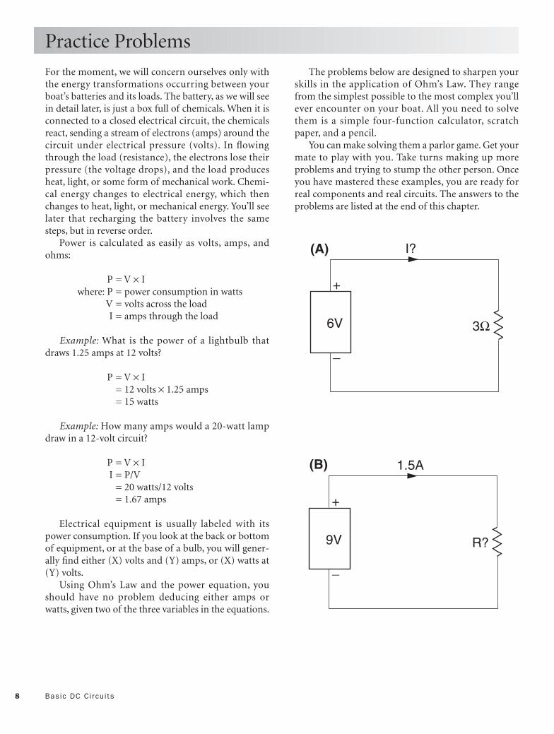
Power is calculated as easily as volts, amps, andohms:
P = V × Iwhere: P = power consumption in watts
V = volts across the load I = amps through the load
Example: What is the power of a lightbulb thatdraws 1.25 amps at 12 volts?
P = V × I= 12 volts × 1.25 amps= 15 watts
Example: How many amps would a 20-watt lampdraw in a 12-volt circuit?
P = V × II = P/V
= 20 watts/12 volts = 1.67 amps
Electrical equipment is usually labeled with itspower consumption. If you look at the back or bottomof equipment, or at the base of a bulb, you will gener-ally find either (X) volts and (Y) amps, or (X) watts at(Y) volts.
Using Ohm’s Law and the power equation, youshould have no problem deducing either amps orwatts, given two of the three variables in the equations.
Practice Problems
The problems below are designed to sharpen yourskills in the application of Ohm’s Law. They rangefrom the simplest possible to the most complex you’llever encounter on your boat. All you need to solvethem is a simple four-function calculator, scratchpaper, and a pencil.
You can make solving them a parlor game. Get yourmate to play with you. Take turns making up moreproblems and trying to stump the other person. Onceyou have mastered these examples, you are ready forreal components and real circuits. The answers to theproblems are listed at the end of this chapter.
+
_
I?
3Ω6V
(A)
+
_
1.5A
R?9V
(B)

9Pract ice Problems
+
_
0.25A
480ΩV?
(C)
+
_
3Ω
I?
12V
I1?
I?
V1
V2
(D)
+
_
3Ω
2A
R2
V
I1
I2
V1?
V2
(E)
+
_ 5Ω
2A
V?
I1
I2
V1
V2
(F)
5Ω
3Ω

10 Basic DC Circuits
Practice Problems
+
_
100Ω
I?
6V
I1 I2 I3
(G)
+
_
R1?V
0.4A 0.2A I3
(H)
R3
100Ω
100Ω
100Ω
+
_
0.5A
R?W?
6V
+
_
I?
10W9V
(I)
(J)

11Pract ice Problems
+
_
0.25A
30WV?
(K)
+
_
20W
I?
12V
(L)
5W
+
_
20W
I?
12V
(M)
10Ω
+
_ 20W@12V
I?
12V
(N)
10Ω

12 Basic DC Circuits
Practice Problems
Answers to Problems:a. I = 2 Ab. R = 6 Ωc. V = 120 Vd. I1 = I2 = I = 1.5 A
e. V1 = 6 Vf. V = 16 Vg. I = 0.18 Ah. R1 = 50 Ωi. R = 12 Ω, W = 3 W
j. I = 1.11 Ak. V = 120 Vl. I = 2.08 Am. I = 2.87 A n. I = 0.7 A
o. I = 0.75 Ap. V2 = 66.7 V, I2 = 1.33 Aq. I5 = 0.036 Ar. V = 21.05 V
+
_
I
12V
5Ω
I4 I5?
+
_
2A
V?I4 I5
(R)
(Q) 10Ω
100Ω
150Ω
6Ω
5Ω 10Ω
100Ω
150Ω
6Ω
+
_
I?
R2
12VR3
4Ω
I2 I3
9V
Voltagesource
+
_
2A
I3
V2?
R1
I2?
(O)
(P)
50Ω 100Ω

This page intentionally left blank

DC Measurements
14
CHAPTER 2
+
–
1
2
34 5 6 7
8
9
10
11
1213
14
DIM
+
–
+
–
+
–
4 V
olts
8 V
olts
12 V
olts
+
–
Copyright © 1993, 2006 by Charlie Wing. Click here for terms of use.

15
Theory is fine, but we need a way to monitor elec-trical systems in order to see if they are workingas expected. Analog test instruments, displaying
current and voltage, allow us to see, at a glance, what ishappening. For the precision required to monitor batteries, however, it is better to use digital test instru-ments.
Very often we need to know only whether there isvoltage present. For these go, no-go tests, a simplehomemade tester is described.
Troubleshooting with testers leads you through thedeductive process of isolating electrical problems.
The practice problems at the end of the chapter willallow you to sharpen your troubleshooting skills.

16 DC Measurements
In Chapter 1, I asserted,“ . . . with Ohm’s Law, you willbe able to understand, predict, and troubleshoot 90%of the electrical problems on a boat.” Let me amendthat figure to 99%.
You will recall that Ohm’s Law allows us to calculatethe theoretical relationships between the voltages, cur-rents, and resistances in a circuit. What if there wereinstruments we could plug into a circuit that wouldshow us the actual values of voltage, current, and resis-tance? By comparing the theoretical and actual values,we would find that either: (1) reality agreed with theoryand all was well in the circuit, or (2) reality disagreedwith theory and there was something wrong in the cir-cuit.
There are instruments that measure volts, amps,and ohms, and using them to compare reality with the-ory is what we call troubleshooting. This chapterdescribes the instruments and their use.
Analog Ammeter (Current Meter) The ammeter hasn’t changed much since it was devel-oped by Jacques d’Arsonval in 1811. In Figure 2.1, cur-rent flows into terminal 1, through the spring, aroundthe moving coil, through a second spring on the back-side, and out through terminal 2. The current in thecoil produces a magnetic field that interacts with thefield of the permanent magnet, forcing the coil to
Analog Test Instruments
rotate about its bearing. The needle attached to the coildisplays the rotation against the scale in the back-ground.
In order that the ammeter be able to measure smallcurrents, the meter movement is very delicate. Themoving coil consists of many turns of fine wire, thesprings are “hair springs” similar to those in a wind-up watch, and the coil pivots on jewel bearings. Typi-cally, 50 µA (50 × 10–6 A or 0.000050 amp) deflects theneedle full scale.
But the currents we are interested in typically rangefrom 0.1 to 100 amps—about one million times 50 µA.You can imagine what would happen if we tried tomeasure the 50-amp charging current in our batteryleads with the 50 µA meter of Figure 2.1.
How can we modify our 50 µA ammeter to measure50 amps? Ohm’s Law to the rescue! Although a perfectammeter would offer zero resistance to the currentflowing through it, real ammeters are made of real wireand so have a finite resistance.
Figure 2.2 shows the resistance, RC, of our amme-ter coil with full-scale current of 50 µA flowing throughit. In parallel with the meter we place a shunt whoseresistance, RS, is 10–6 (one-millionth) of RC. Since thevoltage across both RS and RC is the same, Ohm’s Lawpredicts that IS = 106 (one million) × IC, or 50 amps.
Using this principle, the same 50 µA ammeter canbe made to measure 100 µA, 500 µA, 30 mA, 10 A, 100A, or any other current merely by inserting the appro-priate shunt across the terminals, as shown.
010
20 30 4050
DC AMPS
Permanentmagnet
Movingcoil
NeedleSpring
12Shunt
RCRS
IC50µA
IS50A
Shunt Meter coil
1
2
A
Ammetersymbol
=
Fig. 2.1 D’Arsonval Ammeter
Fig. 2.2 Ammeter Symbol and Internal Resistances

17Analog Test Instr uments
Analog Voltmeter Might we use our little 50 µA d’Arsonval meter to mea-sure voltage as well? Ideally, a voltmeter should mea-sure the voltage across a circuit without disturbing thecircuit. That means it should look like a very high resis-tance—much higher than any of the other resistancesin the circuit.
Figure 2.3 shows a circuit consisting of a 15-voltbattery and 30-ohm load, resulting in a current of:
I = V/RL= 15 volts/30 ohms= 0.5 amp
We have placed a series resistor, RV, inside the caseof our 50 µA ammeter. If we want the ammeter todeflect full scale when the voltage is 15 volts, thenOhm’s Law says that the series resistor that limits thecurrent to 50 µA must be:
IV = V/RVRV = V/IV
= 15 volts/0.00005 amp= 300,000 ohms
The load imposed on the circuit by our voltmeter—one ten-thousandth of the 30-ohm circuit load—isclearly negligible. If the circuit load, RL, had been30,000 ohms instead of 30 ohms, then our voltmeterwould have siphoned off 10% of the current, giving aresult 10% in error, as well as altering the performanceof the circuit.
Voltmeters are simply ammeters with internal seriesresistors of 5,000 to 100,000 ohms per volt of full scale.
Analog Ohmmeter (Resistance Meter) By now you are probably expecting me to tell you thatour 50 µA ammeter can be modified to measure resis-tance as well. You are correct.
To measure the resistance of a resistor or other cir-cuit load, we must isolate that component from the restof the circuit. (Review the practice problems in Chap-ter 1 if you don’t remember why.)
Sometimes we can open a switch; sometimes we candisconnect a terminal; sometimes we have to unsolderone end of the component. Regardless of how we iso-late the item, we measure its resistance indirectly byapplying a test voltage and measuring the resulting cur-rent. Because zero resistance (a possibility in case of ashort circuit inside the component) would draw a pos-sibly destructive high current, we place a known cur-rent-limiting resistor in series with the meter.
Figure 2.4 shows our ohmmeter. Inside its case areour same 50 µA ammeter, a 1.5-volt battery, and aseries resistor, RR. Maximum current will flow, and themeter will deflect full scale, when the resistance beingtested, RL, is zero. From Ohm’s Law:
I = V/RRRR = V/I
= 1.5 volts/0.00005 amp= 30,000 ohms
At the other end of the scale, the current approacheszero, and the needle shows essentially no deflection.Thus, we have a meter representing 0 ohms on theright, ohms on the left, and all other values on a log-arithmic scale in between. Near 0 ohms the meter willbe very sensitive and, as RL approaches , the meterwill be less sensitive.
RV
IA50µA
A
+
–
15V RL
30Ω
IL0.5A
Voltmeter
Fig. 2.3 Using the Ammeter to Measure Voltage
RR
50µA
A
+1.5V
RLOhmmeter
–
–
+
Fig. 2.4 Using the Ammeter to Measure Resistance

18 DC Measurements
Analog Volt-Ohm Meter (VOM)To troubleshoot a circuit, you may need an ammeter, avoltmeter, an ohmmeter, or all three. You may also needa variety of ranges. Conveniently, it is a simple matterto combine all of these functions into a single metercalled a volt-ohm meter (VOM), as in Figure 2.5.
To the 50 µA ammeter, we add a 1.5- or 9-volt bat-tery, assorted precision resistors and shunts, and a mul-tipole, multiposition switch. More expensive VOMsincorporate input amplifiers that increase the inputresistance and decrease the current drawn by the VOM.In this way, the VOM intrudes less on the tested cir-cuit.
Digital Volt-Ohm Meter (DVM)One of the very first clocks was a “water clock”: Waterdripped into a cup. When the cup was full, it tippedover, spilled its contents, and started over. In tipping,it advanced a counter mechanism that indicated thenumber of times it had tripped and thus the passageof time.
A digital ammeter is exactly the same, except that itcounts electrons instead of water drops. The cup is anelectrical capacitor. As the capacitor collects electrons,the voltage across its terminals increases. When thevoltage of the capacitor reaches a predetermined level,the capacitor is discharged, and the charging beginsagain.
The greater the current (flow of electrons), themore rapidly the capacitor charges and discharges. Thecharge/discharge cycles are electronically counted, andthe number of cycles per second are directly propor-tional to current.
The analogy between analog and digital ammeters,voltmeters, ohmmeters, and multimeters is similar.Given a digital ammeter, we just add shunts, resistors,batteries, and rotary switches. Figure 2.6 shows a typi-cal digital volt-ohm meter.
Digital Test Instruments
+–
0
24 6
8
10
0
1020 30
40
50
0
50100 150
200
250
∞
5K1K
500 200 100 5020
10
0
OHMS
DCVma
Rx10Rx1 Rx100
500
250
50
10250
DC mA
10
50
250
500
OHMS
DCV ACV
Fig. 2.5. Volt-Ohm Meter (VOM)
DIGITAL MULTIMETER
DCV
ACV
KΩ
DCmACHECK
DC MA/KΩ200 MA MAX COMMON
DC 1000VAC 750V MAX
+ +–
Fig. 2.6. Digital Volt-Ohm Meter (DVM)

19Digital vs. Analog Test Instr uments
Digital vs. Analog Multimeters So which is better—the analog or digital multimeter?Both are available in a range of sizes, from shirt pocketto benchtop, and both can be had for as little as $10 toas much as $400. To help you decide which is betterfor you, Table 2.1 lists the specifications of two typicalmidpriced units.
The specifications use several prefixes:
µ (micro) = 10–6 —multiply by 0.000001 m (milli) = 10–3 —multiply by 0.001
k (kilo) = 103 —multiply by 1,000 M (mega) = 106 —multiply by 1,000,000
Table 2.1 Typical Analog and Digital Multimeter Specifications
Analog DigitalSpecification Multimeter Multimeter
DC volts lowest range 250 mV 300 mV
highest range 1,000 V 1,000 V
accuracy1 ±4% ±0.2%
AC volts lowest range 5 V 3 V
highest range 1,000 V 750 V
accuracy1 ±4% ±0.5%
DC amps lowest range 50 µA 300 mA
highest range 10 A 10 A
accuracy1 ±3% ±0.5%
Resistance lowest range 2 k 300
highest range 20 M 30 M
accuracy1 ±3% ±0.2%
1 Accuracy as percent of full scale
A glance at an old-fashioned watch gives you a senseof the approximate time very quickly. A digital watch,however, first requires recognition of the numbers dis-played, then an interpretation of the significance of thenumbers. The same is true of analog and digital multi-meter displays.
If you wish to know simply whether your battery ischarging or discharging (roughly 14 versus 12 volts),the analog meter with ±4% accuracy (±0.6 volt on a15-volt scale) will do the job. But if you want to knowthe percentage of charge remaining in your battery,where the same ±0.6 volt represents ±50% of batterycapacity, you’d better use a digital meter with its ±0.2%(±0.03 volt on a 15-volt scale) accuracy.
Digital vs. Analog Panel Meters Ammeters and voltmeters (Figures 2.7 and 2.8) areused in distribution and circuit breaker panels to mon-itor battery voltage and rate of charge/discharge. Ananalog “battery charge indicator” is simply a voltmeterwith its needle pegged at the left until the voltagereaches approximately 8 to 10 volts, thus expanding thescale over the useful voltage of a 12-volt battery.
Digital panel meters are slowly replacing analogmeters. They cost no more to produce than the analogvariety and are far more accurate, so one hopes theirprices will soon drop.
Digital vs. Analog Test Instruments
0
5 1015
DC VOLTS
010 20 30 40
50
DC AMPS
810 12 14
16
DC VOLTS
DISCHARGED 0 50 100 CHARGING
BATTERY CONDITION
1211109 13 14 15
DISCHARGED 0 50 100 CHARGING
DC Voltmeter
DC Ammeter
Battery ChargeIndicator
Battery ChargeIndicator
Fig. 2.7 Analog Panel Meters
DC VOLTS
DC AMPS
Digital Ammeter
Digital Voltmeter
Fig. 2.8 Digital Panel Meters

20 DC Measurements
Most of the wiring problems on a boat are of the go,no-go variety. All DC circuits start at the boat’s 12-voltbattery. As you check a suspect circuit farther and far-ther from the battery, there either is or isn’t voltage present. At the first point you find no voltage present,you can be sure the problem lies between this point andthe last point where voltage was present.
The most common marine wiring problems are dueto corrosion of connections and contacts. When coppercorrodes, it forms green copper oxide—an excellentelectrical insulator. As corrosion progresses, more andmore of the contact surface through which currentflows is eliminated. Eventually, there is so much resis-tance and voltage drop across the contact that thereduced voltage affects the load. If the load is a lamp,for example, the lamp will dim. If the load is a motor,the motor will slow down or not start at all.
There are two simple, do-it-yourself, troubleshoot-ing devices you may end up using more than yourfancy multimeter. The first is nothing more than anautomotive bulb with attached test leads; the second isa Piezo electric alarm buzzer with test leads.
Figure 2.9 shows a typical 12-volt DC automotivebulb you can purchase at any Wal-Mart or auto partsstore. Get a pair of high-quality “test leads” at Radio-Shack. These will be rubber-insulated, very fine-stranded #14 to #18 wire with alligator clips, bananaplugs, or minitest tips attached. Solder the test leads tothe side and base of the bulb, as shown, or to a lampsocket. Don’t worry about ever having to replace thebulb. It is rated 5,000 hours at 13.5 V, so the only wayit should fail is if you step on it or try to test a 110-voltcircuit with it.
The second tool is similar but produces a noiseinstead of a light. As in Figure 2.10, solder test leads toa 3 V–16 V Piezo electric buzzer, which can be foundat an electronics store for under $5.
If you want to get fancy, assemble both the light and
Homemade Testers
the buzzer in a small box with a switch that allows youto use either the light, the buzzer, or both simultane-ously.
When connected to 12 volts, the bulb will glowbrightly. If the voltage is low, the bulb will glow, butdimly. If there is no voltage, the bulb will not glow.Similarly, at 12 to 16 volts, the buzzer will screech; at 3to 12 volts, the buzzer will sound fainter; at less than 3volts, the buzzer will not sound at all. In a noisy envi-ronment, the light works best. In bright sunlight, thebuzzer is best.
Next pick your tips. I find a set of interchangeabletips, as shown in Figure 2.11, very useful. Permanentlyattached to the test leads are banana plugs. These can be plugged into banana-to-alligator adapters,banana-to-minipin adapters, and banana-to-miniprobeadapters. I choose the adapters based on wire size andwhether I’m using one hand or two. Also handy is a sin-gle 50-foot extension lead with male and femalebanana plugs, so that I can extend one of the test leadsthe length of a boat or a mast.
Fig. 2.9 Homemade Test Light
Fig. 2.10 Homemade Test Buzzer
Banana plug Test lead
Banana plug Test lead
Banana plug Test lead
Banana plug Test lead
Banana-to-alligator adapter
Banana-to-minipin adapter
Banana-to-miniprobe adapter
Fig. 2.11 Interchangeable Test-Lead Tips

21Troubleshooting
Multimeters, test lights, and test buzzers are all useful introubleshooting circuits. Only where a precise voltageor a precise resistance is needed will the multimeter bemore useful than the simpler light or buzzer, however.For simplicity, the examples and illustrations that fol-low will show only the simple test light. Just rememberthat where the test light is on, the buzzer would sound,and the multimeter would show a voltage, but wherethe test light is off, the buzzer would be silent, and themultimeter would show no or low voltage.
Figure 2.12 shows a simple cabin light circuit. Thepositive side of battery 1 is connected to terminal 1 of
the battery-select switch by a wire. The common termi-nal of the battery switch feeds the positive bus bar inthe distribution panel. The cabin light circuit originatesat the “cabin lights” circuit breaker (or fuse) connectedto the positive bus and then runs out of the panel to thecabin lights, which are connected as parallel loads.
At the light fixture, the positive wire feeds the on/offswitch, which then controls the bulb. The other termi-nal of the bulb connects to the negative wire, whichruns back to the negative bus in the distribution paneland the negative terminal of the battery, completing thecircuit.
Troubleshooting
1 2
BOTH
OFF
Negative bus bar
Positive bus bar
Cabinlight
+
−
Batteryswitch
Cabinlightscircuit
breaker Cabinlight
switch
2
3 45
6 78
9
10
1112
13
Battery 1
1
14
Negative bus bar
Positive bus bar
+
–Battery 1
Cabinlightscircuit
breaker Cabinlight
switch
Cabinlight
Batteryswitch
1
2
3 4 5 6 78
9
10
11
121314
Fig. 2.13 Typical Cabin Light Wiring Diagram
Fig. 2.12 Typical Cabin Light Circuit
Figure 2.13 shows the same cabin light circuit in theform of a wiring diagram, using the standard compo-nent symbols listed in Figure 6-1. Note that the circuitload consists of lamps, which are nothing more thanresistances that glow white hot. We could equally wellhave shown the load as parallel resistances, as in previ-
ous examples. In both Figures 2.12 and 2.13, fourteenpoints to which we could connect test leads are num-bered. As we troubleshoot the circuit, we will connectour test light to pairs of these points to see whethervoltage is present.

22 DC Measurements
Turn all circuit switches to their on positions (Fig-ure 2.14). The cabin lamps light up, meaning there isnothing wrong with the circuit. Since the wire andswitches are designed to have near-zero resistance, weexpect there to be no voltage drop between points 1
Troubleshooting
and 10. There should also be no voltage change frompoints 11 to 14. With one test lead on any of points 1to 10 and the other lead on points 11 to 14, the test lightshould light, but with both leads on either the positiveor negative side, the test light should not light.
+
–
1
2
34 5 6 7
8
9
10
11
1213
14
Fig. 2.14 Properly Working Cabin Light Circuit
+
–
1
2
34 5 6 7
8
9
10
11
1213
14
Fig. 2.15 Defective Cabin Light Circuit
In Figure 2.15 we investigate a cabin lamp that willnot light. All of the switches in the circuit are on, yet thelight remains off. Furthermore, all of the other cabinlights in the same circuit do work.
We could start testing at points 1 and 14 and workour way toward the light. If we do, we’ll find that thetest lamp lights at every point, just as it did with theprevious example of a normal circuit. If we suspect aburned-out bulb, however, we can save a lot of time by
applying the test leads to points 10 and 11 immedi-ately and discover that the circuit is OK all the way tothe bulb holder.
At this point I’d simply replace the bulb. If you wantto be sure it’s the bulb and not the bulb holder, how-ever, get out your multimeter and measure the resis-tance between the bulb contacts. If the multimeterreads infinite ohms, you know you have the culprit—aburned-out filament.

23Troubleshooting
In Figure 2.16, we uncover a broken switch in thecabin light. We start as in the previous example with acabin light that will not light up with all switches inthe on position.
We suspect that the bulb filament has burned out,so we place our test lamp leads between points 10 and11. The test lamp does not light. We therefore knowthat 12 volts is not reaching point 10. Next we placethe test leads between 8 and 11. Now the test lamp
lights up. The problem must be either in the switch orthe short wire between the switch and the bulb holder.
We place the test leads across 8 and 9. Now boththe test lamp and the cabin light glow dimly. What’sgoing on? Our test lamp has bridged the broken switch,but acts like a load in series with the cabin light. Thisreduces the current and brightness of both bulbs. Thebulb is OK, but the light switch must be replaced.
+
–
1
2
34 5 6 7
8
9
10
11
1213
14
DIMLYLIT
DIMLYLIT
Fig. 2.16 Uncovering a Defective Switch
+
–
1
2
34 5 6 7
8
9
10
11
1213
14
DIM
+
–
+
–
+
–
4 V
olts
8 V
olts
12 V
olts
+
–
Fig. 2.17 Troubleshooting with the Multimeter
In the previous two examples, a component in thecircuit had failed, resulting in an open circuit and zerocurrent.
In Figure 2.17, we know the circuit is closed becausethe lamp is lit. But the lamp is dim. This is a very famil-iar phenomenon with flashlights—the light dims, but
when we shake or hit the case the light becomes brightagain.
The problem is due to poor contact. In a boat, poorcontact is usually caused by corrosion of switch con-tacts or connectors. We will use this example todemonstrate the use of the multimeter.

24 DC Measurements
Just to be sure our battery isn’t low, we measurebetween points 7 and 12, accessed behind the distribu-tion panel. The meter reads 12 volts, so we know thebattery is charged, and the circuit is OK up to the pointwhere it leaves the panel for its run to the cabin lights.
Next, we try the other cabin lights in the circuit.They light normally, so we know our problem liesinside the dimmed light fixture. We remove the fixturebase, exposing the internal switch and bulb holderwiring. We measure the voltage across the lamp itself,points 10 and 11, and the meter reads only 8 volts.Next, we measure the voltage across the switch, points8 and 9. The meter reads 4 volts.
We have found the missing volts! Bad switch con-tacts are providing a resistance in series with the lamp,resulting in a voltage drop. In fact, one-third of thepower in the circuit is being consumed within theswitch, which we note is hot to the touch.
If we suspected internal resistance in the switch,why didn’t we simply place the multimeter in the ohmsmode and measure the resistance of the switch directlybetween points 8 and 9?
We could have, provided (and this is an extremelyimportant “provided”) we first opened the circuit byturning off either the battery switch or the circuitbreaker.
If we tried measuring the resistance without open-ing the circuit, the 12-volt battery would still be in thecircuit. Figure 2.4 showed that an ohmmeter consistedof a delicate 50 µA ammeter in series with an internalresistor and 1.5-volt battery. By placing the ohmmetercircuit in series with the cabin light circuit, we haveeffectively added or subtracted (depending on polarity)the 12-volt battery from the 1.5-volt battery. In the bestcase, the resistance reading will be grossly in error. Atworst, we will burn out the 50 µA ammeter.
In general, to measure the resistance of a circuitcomponent, you must first remove the componentfrom the circuit by disconnecting one of its leads.Never try to measure resistance within a circuit with alive voltage.
A similar caution applies to measuring current in acircuit directly with a multimeter. Many inexpensivemultimeters are designed to measure currents of up to250 mA (0.25 amp). Others contain an internal shuntthat allows measurements up to 10 amps. Make surethe current in a circuit is less than the maximum yourmeter can handle. Otherwise, you may blow the fuse or,worse, the meter itself.
A common mistake is to think you are measuring avoltage when, in fact, the multimeter is in the Ampsposition. The result is the same—something will blow.
Practice Problems Table 2.2 below is intended to give you practice in trou-bleshooting a circuit. First, cover up column 3, then,referring to Figure 2.12, see if you can guess the causeof the problem, given the symptoms listed in columns1 and 2. Column 3 lists the most likely causes.
Table 2.2 Symptoms and Causes
Test Light Test Light ON OFF
Between Between Most Likely Cause
— 1 and 14 Dead battery
1 and 14 2 and 14 Positive battery cable
2 and 14 3 and 14 Battery switch off or defective
3 and 14 4 and 14 Bad connection or broken cable between battery switch and positive bus
6 and 14 7 and 14 Breaker off, defective breaker, or blown fuse
7 and 14 8 and 14 Broken wire from breaker to light switch
8 and 14 9 and 14 Switch off or defective
9 and 14 10 and 14 Broken wire between light switch and bulb holder
10 and 14 11 and 14 Burned-out lamp or poor contact between bulb and holder
10 and 14 10 and 13 Negative battery cable
10 and 13 10 and 11 Bad connection at negative bus or broken wire from bus to bulb holder
Troubleshooting

This page intentionally left blank

Batteries
26
CHAPTER 3
Sponge lead
Sulfuric acidelectrolyte
Sulfatedregion
Lead/Antimony grid
Lead dioxide
Porousseparator
Unreactedregion
Lead sulfate– +
Copyright © 1993, 2006 by Charlie Wing. Click here for terms of use.

27
Except for the diesel engine, the greatest mysteryto most boaters is the black box called the ship’sbattery.
What is a battery? Exactly what is going on insidethat black box? In this chapter, you will find the simpleanswers and a few messy details as well.
Although it is more complex than simple conduc-tors and resistors, it is useful to have an electricalmodel of the battery.
Monitoring batteries is the key to their perfor-mance. Monitoring the discharge/charge cyclerequires an understanding of discharge characteris-tics, battery discharge ratings, and charging character-istics. You’ll discover that charging recommendationsvary between battery types.
In selecting batteries for your boat, you have severalchoices. In addition, you have to size the batteries toyour load and decide whether to install multiple batter-ies in series or in parallel.
Safe installation involves electrical and mechanicalconsiderations, both of which are covered by ABYCstandards.

28 Batter ies
Probably no aspect of a boat is less well understood byits owner than its batteries. Our “knowledge” of bat-teries often consists of a few remembered facts from ahigh school chemistry course, experience with our ownboats and automobiles, and, unfortunately, a barrage ofadvertising hype.
As with most of today’s mass-marketed products,engineering takes a backseat to marketing. Meaningfulspecifications and instructions have been replaced bytechnical-sounding words such as “heavy-duty,”“marine-grade,” “deep-cycle,” and “Die-Hard.” Somemanufacturers have gone so far as to promise boatingnirvana—a battery you can stick anywhere in your boatand never give it another thought.
This is most unfortunate because: (1) it is not true,and (2) nothing is more important to the cruising boatthan an adequate and reliable 12-volt system. Withouta reliable source of 12 volts, most of us would have nolighting, refrigeration, navigation, or communication.In fact, we couldn’t even start our engines.
This chapter explains what you need to know inorder to select and then maintain the batteries that arethe heart of your boat’s electrical system.
To read battery manufacturers’ literature, you wouldthink that today’s batteries represent recent technolog-ical breakthroughs. The truth is that the chemistry ofThomas Edison’s batteries of 100 years ago is identicalto the chemistry of today’s batteries. But what aboutthe new, sealed, gel-cell batteries you can store underyour bunk? You are right—they are newer. They werepatented in 1933.
Most of what you need to know about lead-acidbatteries can be observed in a galley experiment using aglass containing a cup of battery acid (siphon somefrom your battery, or buy a quart at the auto partsstore), two lengths of lead solder, two D-cells, a batteryholder, and a voltmeter. Warning: battery acid is strongso wear rubber gloves and be very careful.
Place the D-cells in the battery holder as in Figure3.1. Connect one length of solder to the negative end,the other length to the positive end of the batteryholder, and dip their ends into the acid.
Bubbles will form and rise in the acid. Soon you’llnotice one of the lengths of solder turning brown.Remove the batteries and connect the voltmeter to thesolder, as shown in Figure 3.2. The voltmeter will readabout 2 volts.
You have just manufactured and witnessed theoperation of a lead-acid cell—the very same thing that
What Is a Battery?
is in your boat’s batteries. The only difference is thatyour boat’s batteries consist of either three of these cellsin series (6-volt battery) or six cells (12-volt battery).
– +
Two C- or D-cells in battery holder
– +
Lead solder
Battery acid(sulfuric acid)
Fig. 3.1 A Galley Battery, Step 1
Volt-Ohmmeterset on DC Volts
– +
Lead solder
Battery acid(sulfuric acid)
Fig. 3.2 A Galley Battery, Step 2

29What Is a Batter y?
What Is Going On? What you have just witnessed is the reversible chemi-cal reaction found in all lead-acid batteries:
charging <=
PbO2 + Pb + 2H2SO4 = 2PbSO4 + 2H2O=>
discharging
Figure 3.3 shows the four phases of a lead-acid cellcharge/discharge cycle. (See page 32 for more on spe-cific gravity, SG.)
Fully charged. In the equation, application of an exter-nal charging voltage has driven the reaction all the wayto the left. The negative electrode has become pure lead(Pb), the positive electrode is now pure lead peroxide(PbO2), and the sulfuric acid electrolyte (H2SO4 +H2O) is at its maximum concentration.
Discharging. By connecting a load (shown as a resistorin Figure 3.3), we complete the electrical circuit, allow-ing electrons to flow from one electrode to the otherand the chemical reaction to proceed. The H2SO4
breaks into H and SO4 ions (molecules with eitherextra or missing electrons). The H is attracted to thepositive electrode where it steals the O2 from the PbO2
and forms water, H2O. The now free Pb combines withthe SO4 ions to form PbSO4 in place of the PbO2. At thenegative electrode, SO4 ions also combine with the purePb to form more PbSO4. Thus, both electrode materialsare converted to lead sulfate, PbSO4, while the elec-trolyte loses sulfuric acid, H2SO4, gains water, H2O, andbecomes more dilute.
Fully discharged. The cell is fully discharged when itruns out of one of the necessary ingredients. Either thePbO2 has been totally converted to PbSO4, or all of theSO4 ions in the electrolyte have been used up, reduc-ing it to pure water. In either case, PbO2 and electrolytestrength have been minimized and PbSO4 maximized.
Charging. By connecting a charging voltage to the cellwe drive the electrons and the reaction in the reversedirection. Ideally, the negative electrode is restored topure PbO2, the positive terminal to pure Pb, and theacid electrolyte to its maximum strength.
H2SO4 maxH2O minSG max
Pb PbO2
H2SO4 ↓H2O ↑SG ↓
Pb ↓PbSO4↑
PbO2 ↓PbSO4↑
+
H2SO4 minH2O maxSG min
Pb minPbSO4max
PbO2 minPbSO4max
H2SO4 ↑H2O ↓SG ↑
Pb ↑PbSO4↓
PbO2 ↑PbSO4↓
Load
I
I
Charger
1Fully
Charged
2Discharging
3Fully
Discharged
4Charging
-
-
-
-
+
+
+
Fig. 3.3 The Charge/Discharge Cycle

30 Batter ies
The good news is that the chemistry of the lead-acidbattery is simple. The bad news is that the way in whichit actually happens is a bit more complex.
Figure 3.4 shows a cross section of a cell. Both pos-itive and negative electrodes are immersed in elec-trolyte. The reactive materials, lead and lead peroxide,are suspended on lead grids that serve to both supportthe materials and conduct electric current. So far, sosimple. Now for the complications:
• Boat batteries are bounced around. In order thatthe plates not touch each other and short-circuit thecell, the many closely spaced plates (electrodes) areinterleaved with porous fiberglass separators.
• The lead grid is chemically and electrically com-patible with the active materials that it supports, but itis not very strong. To increase strength, it is alloyed witheither antimony (conventional wet, deep-cycle batter-ies) or calcium (sealed, maintenance-free batteries).
• When the discharge reaction starts, lead sulfatefirst forms at the electrode surfaces. As discharge con-tinues, the already formed sulfate forms a barrierbetween the electrolyte and the unreacted materialbeneath, slowing the reaction and limiting the current.The greater the surface area and thinner the plates, thegreater the possible current flow. Engine-starting bat-teries have many thin plates in order to provide largecurrents for short periods. The electrodes are also“sponged” (made full of minute holes) in order to fur-ther increase surface area.
• Lead, lead peroxide, and lead sulfate are not of thesame density. When one replaces the other, expansionand contraction tend to dislodge the materials from thegrids. Each time a cell is cycled, a small amount of leadsulfate is shed and falls to the bottom of the cell. Even-tually the accumulation at the bottom may short outthe plates. The more complete the reaction (the deeperthe discharge), the greater the loss. Batteries designedfor deep-cycling have fewer but thicker plates.
• When a battery is fully charged, all of the lead sul-fate of the positive plate has oxidized to lead peroxide.Further charging (overcharging) oxidizes the lead ofthe grid as well, turning it into lead peroxide. Lead per-oxide has little mechanical strength, and the grid willultimately fall to the bottom of the cell.
• The rest of the overcharging energy goes intohydrolysis—separation of the water of the electrolyteinto H2 and O2—which we saw as bubbles in ourkitchen battery. Various tricks are employed in sealedbatteries to recombine the gases into water, but, if over-charging and gassing are too vigorous, all batteries vent
A Few Messy Details
gas and lose electrolyte. Water can be replaced in a con-ventional wet-acid battery. In a sealed or gel-cell bat-tery, it cannot.
• As we have seen, charging regenerates the H2SO4
electrolyte. Pure H2SO4 is 1.83 times as dense as water.As the H2SO4 is generated, it tends to sink. Since it is theH2SO4 that makes the electrolyte conductive, itsabsence at the top of the cell limits the acceptance ofcharging current. In a conventional wet-acid battery,acceptance is slow until gassing begins. Rising gas bub-bles then mix the electrolyte, and acceptance increases.
• Gelled-electrolyte batteries capture the electrolytein a gel, preventing stratification and increasing initialcharge acceptance. “Starved electrolyte batteries”accomplish the same goal by limiting the electrolyte tojust enough to saturate the porous separators.
• Most serious is the phenomenon of sulfation. If abattery is left in a discharged state (i.e., with much of itselectrodes in the form of PbSO4), the initially fine, softdeposits grow into larger, harder crystals that clog theholes of the sponged electrodes. The battery becomesdifficult to charge and displays reduced capacity. Vigor-ous overcharging and bubbling (equalization) canbreak up and dislodge the crystals, resulting in recoveryof much of the original capacity. However, each time itis done, the plates shed more material and get closer tothe end of their useful lives.
So you see that, although the basic chemistry of alllead-acid batteries is the same, there are enough varia-tions in construction to allow battery company mar-keting departments a field day.
Sponge lead
Sulfuric acidelectrolyte
Sulfatedregion
Lead/Antimony grid
Lead dioxide
Porousseparator
Unreactedregion
Lead sulfate– +Fig. 3.4 Cross Section of a Lead-Acid Battery Cell

31Electr ical Model of Batter ies
An ideal voltage source would supply unlimited cur-rent, with no drop in voltage. Considering the con-struction of the battery shown in Figure 3.4 and themessy complications described above, it is obvious thatthe lead-acid battery is not an ideal source.
For current to flow, the SO4 and H ions have to findtheir way through the electrolyte. Resistance to thismovement is evidenced as an internal electrical resis-tance, Ri.
When we disconnect a battery from an external cir-cuit, no current should flow—at least theoretically.However, there is still voltage inside the cell ready andwilling to supply current to anything that might bridgethe gap between the battery’s electrodes. Impurities in the electrolyte, as well as dirt and spilled electrolyteon the surface of the battery, provide such paths. Theyresult in a parallel resistance, Rp, acting to self-discharge the battery. This is why you should never addanything but distilled or demineralized water to yourbattery and why it is a good idea to keep its surfacesclean.
Figure 3.5 shows the electrical model of the batteryconsisting of an ideal voltage source with a series inter-nal resistance, Ri, and a parallel self-discharge resis-tance, Rp. Since chemical reactions always speed upwith temperature, both resistances decrease withincreasing temperature.
Ri in a new lead-acid battery is very small—of theorder 0.01 ohm. It can be measured by drawing aknown current and observing the drop in voltage at theterminals.
Example: We monitor the current drawn by a startermotor as 200 amps. As soon as we switch on the starter,we observe a drop in battery voltage from 12.5 to 9.5volts. The battery’s internal resistance, Ri, is then:
Ri = V/I = (12.5 – 9.5) volts/200 amps= 0.015 ohm
The voltage must be measured at the battery ter-minals to eliminate the drop in the battery cables.
Rp is typically quite large—on the order of 1,000 to10,000 ohms. It can be deduced by observing the dropin battery stored capacity over time.
Figure 3.6 shows the self-discharge of a typical newbattery at different temperatures.
Example: At 68°F, the battery loses the first 10% ofcharge in three months. If this is a 100 Ah battery, itloses 10% of 100 Ah, or 10 Ah over a period of 90 days.Since there are 24 hours in a day, the discharge period is 90 × 24, or 2,160 hours. The average discharge cur-rent was thus 10 Ah/2,160 hours = 0.0046 amp. UsingOhm’s Law,
Rp = V/I = 12 volts/0.0046 amp= 2,600 ohms
The effect of temperature on Rp is evident from thedischarge curves. Performing the same calculations asabove, we find that Rp at 40°F is 7,900 ohms, while at104°F it has dropped to just 930 ohms.
Electrical Model of Batteries
+
–
Ri
Rp
12V
+
–
Fig. 3.5 Electrical Model of the Battery
100
90
80
70
60
50
Ret
aine
d C
apac
ity, %
Storage Time, Months9630 12 15 18
104°F
86°F
68°F
41°F
Fig. 3.6 Battery Self-Discharge vs. Time

32 Batter ies
Determining State of ChargeShort of taking a battery apart and weighing theamounts of chemicals present, how can we determinethe state of charge? Later we will describe battery-charge regulators/monitors that regulate and keeptrack of the amperes flowing into and out of a battery.For now, we will consider the more basic methods thathave been used since batteries were invented.
First, in what sorts of units do we measure theamount of energy stored in a battery? As stated inChapter 1, electrical energy is measured in watt-hours—the watts of power dissipated by the currentflowing through a load times the duration of the flowin hours. Again, watts equals current times voltage:
W = I × Vwhere I = amps through the load
V = volts across the load
However, since the voltage of a battery is alwaysnominally 12 volts until nearly discharged, it is custom-ary to drop the term “volts” and refer to the amount ofenergy drawn from or stored in a battery simply asampere-hours (Ah).
As an example, suppose we charge a battery at theconstant rate of 50 amps for 2 hours. At the end of 2hours we will have put 50 amps × 2 hours, or 100 Ah,into the battery. Then let’s draw a constant 5 amps fromthe battery for 10 hours. At the end of the 10 hours wewill have drawn 5 × 10, or 50 Ah, out of the battery.Theoretically there should be 100 Ah – 50 Ah, or 50 Ah,still in the battery.
Battery electrolyte is a mixture of water (density1.000 gram/cubic centimeter) and sulfuric acid (den-sity 1.830 grams/cubic centimeter). Since flow of elec-tricity into and out of a battery results in either the gen-eration of sulfuric acid or the loss of sulfuric acid, theamount of stored energy in a battery is, therefore, a lin-ear function of the density of the electrolyte.
Electrolyte density is usually expressed as its specificgravity—the ratio of its density to the density of water.
Specific gravity (SG) is measured with a batteryhydrometer calibrated for the range of electrolyte den-sities normally found in a battery, 1.000 to 1.300. Donot confuse a battery hydrometer with an antifreezecoolant hydrometer, which is designed to measure SGsof less than 1.000. When a sample of electrolyte isdrawn into the hydrometer, a float indicates the SG.However, the indicated SG must be corrected to what itwould be at a standard temperature, 80°F. Figure 3.7shows the corrections to make.
Monitoring Battery Health
Example: A battery is located in the engine com-partment. The temperature of the electrolyte is 95°F.The hydrometer reads 1.250. What is its SG, correctedto 80°F? Answer: 1.250 + 0.006 = 1.256.
Figure 3.8 shows the relationship between state ofcharge and electrolyte SG for a typical new lead-acidbattery. The form of the relationship is always correct,but:
1. The high and low SG end points are particular tothe individual battery, depending on age, condi-tion, and the preferences of the manufacturer.High SG is more often between 1.265 and 1.280.
2. The SG has been measured only after the bat-tery has rested for a time sufficient for the elec-trolyte to become homogeneous through diffu-sion, usually considered to be 24 hours.
3. The SG has been corrected to the standard tem-perature of 80°F.
Battery manufacturers can make the SG any valuethey wish. A more concentrated electrolyte (higher SG)produces higher voltage and increased capacity, but italso leads to shorter battery life. SGs are made higher incolder climates. Most new battery high SGs fall in therange 1.265 to 1.280.
Figure 3.9 shows a second electrochemical relation-ship—this time between SG and voltage. The open cir-cuit (no current being withdrawn) voltage of a singlelead-acid cell is determined by the homogeneous, tem-perature-corrected electrolyte SG as:
−0.032
−0.028
−0.024
−0.020
−0.016
−0.012
−0.008
−0.004
0.000
+0.004
+0.008
+0.012
+0.016
0°F10°F20°F30°F40°F50°F60°F70°F80°F90°F
100°F110°F120°F
At these temperatures
Add tospecific gravity
Fig. 3.7 Correcting Measured Specific Gravity for Temperature

33Monitor ing Batter y Health
V = 0.84 + SG For a 12-volt (six-cell) battery the relationship
becomes that in Figure 3.9:V = 6 × (0.84 + SG)
Using either Figure 3.8 or Figure 3.9 requires thatwe actually measure the SG of the electrolyte. Thisoperation is messy, destructive of clothing, awkwardin the spaces where batteries are usually stowed, andimpossible with a sealed battery.
Fortunately, Figures 3.8 and 3.9 can be combined,resulting in the more convenient relationship betweenstate of charge and open-circuit voltage shown in Fig-ure 3.10. The figure shows that, after 24 hours of rest,this battery would read 11.6 volts when fully dis-charged, 12.7 volts when fully charged, and 12.2 voltswhen 50% discharged.
If we can wait 24 hours, determining the remain-ing capacity of a battery is simple using an accuratevoltmeter. The 24-hour rest period is provided byswitching between two battery banks daily.
Why do we say the battery is fully discharged at 11.6volts when the battery obviously has some amount ofcharge remaining? It is destructive to discharge a mul-ticelled, lead-acid battery to 0 volts. With even smalldifferences between cells, as 0 volts is approached, thestronger cells can drive the weaker cells into reversedpolarity. Their grids will be damaged by being con-verted to PbSO4. To avoid damage, “fully discharged”is defined as 10.5 volts at the 20-hour discharge rate.For example, for a 100 Ah battery, fully discharged isthe point where the voltage reads 10.5 V, at a dischargecurrent of 100 Ah/20 hours = 5 amps.
Self-Discharge and Winter Storage House batteries are very heavy, so it would be nice ifwe could leave the really big ones on the boat over thewinter. Pure water (fully discharged electrolyte) wouldfreeze and crack the battery case. However, fullycharged electrolyte (SG = 1.265) freezes at –72°F, whilehalf-charged electrolyte (SG = 1.190) freezes at –12°F.
The question for northern boatowners thusbecomes how quickly a battery that has been washedwith a baking-soda solution, rinsed with fresh water,fully charged, and disconnected from its leads will self-discharge. According to Rolls Battery, at an averagetemperature of 50°F, such a battery would discharge atabout 0.0003 SG per day. To drop from SG 1.265 to SG1.190 (freezing point –12°F) would take 250 days.
01.050 1.300
Specific Gravity after 24 Hours
Rem
aini
ng C
apac
ity, %
1.100 1.150 1.200 1.250
20
40
60
80
100
50% discharge
1.000
Spe
cific
Gra
vity
afte
r 24
Hou
rs
1.050
1.100
1.150
1.200
1.250
1.300
11.6 11.8 12.0 12.2 12.4 12.6 12.8Open-Circuit Battery Voltage after 24 Hours
011.6 12.8
Open-Circuit Voltage after 24 Hours
Rem
aini
ng C
apac
ity, %
20
40
60
80
100
11.8 12.0 12.2 12.4 12.6
50% discharge
Fig. 3.8 Battery Remaining Capacity vs. Specific Gravity
Fig. 3.9 Battery Open-Circuit Voltage vs. Specific Gravity
Fig. 3.10 Battery Remaining Capacity vs. Voltage

34 Batter ies
Earlier we noted the custom of measuring batterycapacity in Ah. At small charge and discharge rates, thelosses due to internal resistance are small, and the num-bers of Ah we can withdraw very closely approximatethe numbers of Ah we have put in.
When discharging at high currents, however, thereis an apparent loss of battery capacity. As discharge cur-rent increases, the internal voltage drop through thebattery’s internal resistance increases, so the 10.5-voltcutoff point is reached sooner. Thus cutoff voltage forstarter-motor applications is reduced to 7.2 volts.
Figure 3.11 shows discharge voltage vs. time at frac-tions of the 20-hour Ah capacity, C. When a battery’scapacity, C, is stated as 200 Ah at the 20-hour dischargerate, it means that, when discharged at a constant rateof 0.05C (0.05 × 200 = 10 amps), the output voltage willfall to the zero-capacity cutoff of 10.5 volts in 20 hours.If the discharge rate is increased to 0.25C (50 amps),however, it will fall to 10.5 volts in about 3 hours. In thefirst case, 10 amps × 20 hours = 200 Ah. In the secondcase, 50 amps × 3 hours = 150 Ah. Discharged at 0.25C,the battery seems to have only 75% of its rated capacity.
This apparent loss of capacity vs. discharge rate isclearly shown in the more general curve of Figure 3.12.Note, that if we discharge at less than the 20-hour rate,the apparent capacity is greater than 100%. If this doesnot surprise you, it shows that you understand theeffect of battery internal resistance.
Since internal resistance is strongly affected by elec-trolyte temperature, we would expect a family of suchdischarge curves for different temperatures.
Figure 3.13 shows capacity vs. both discharge rateand temperature. As in Figure 3.12, at 80°F, a batterydischarged at five times the 20-hour rate (5 × 0.05C =0.25C) gives us 75% of its rated capacity. At 0°F and0.25C, only 45% of the rated capacity is available.
You may be wondering how this loss of Ah squareswith the principle that electrons are neither created nordestroyed. Where did all those electrons go?
They are still there in the battery—they just got leftbehind. Due to the heavy current, the electrolyte in theplates was temporarily depleted. If we allow the bat-tery to rest awhile, electrolyte ions will diffuse into theplates, and, when we start drawing current again, we’llfind the voltage has recovered to more than 10.5 volts.This recovery is a familiar phenomenon to those whohave had to start balky automobiles in subzero weather.If we are, in fact, willing to withdraw the current at amuch lower rate, we will succeed in retrieving nearly100% of our invested Ah.
Discharge Characteristics
1 2 3 5 10 30 1 2 3 5 10 20HoursMinutes
Discharge Time at 68°F
13
12
11
10
9
8
7
Bat
tery
Vol
tage
Und
er L
oad
10.5V
7.2V 2C 1C
.25C .05C
2520151050Discharge Time, Hours
100
110
90
80
70
60
50
40
% o
f 20
Hr
Cap
acity
Ava
ilabl
e
0 20 40 60 80 100
100
120Temperature, °F
0
20
40
60
80
120
% o
f 20
Hr
Cap
acity
20 hr rate x1
x5
x20
x40
Fig. 3.11 Battery Discharge Characteristics
Fig. 3.12 Capacity as a Function of Discharge Time
Fig. 3.13 Capacity as a Function of Temperature

35Discharge Character ist ics
Battery Discharge RatingsBecause batteries are used in widely varying applica-tions, several standard capacity ratings have evolved:
1. Ah at 20-hour rate—amps a battery will supply for20 hours at 80°F, before dropping to 10.5 volts,times 20 hours.
2. Cold cranking amps (CCA)—minimum number ofamps a battery can supply for 30 seconds, at a tem-perature of 0°F, before dropping to 7.2 volts.
3. Reserve capacity—number of minutes a battery willsupply a specified constant current (usually 25amps) at 80°F, before dropping to 10.5 volts.
The first two ratings are of most interest to boat-owners. When running on battery power, the “house”batteries are usually required to run from the time theengine is turned off until it is turned on again. For acruising boat, the period is likely to last from 16 to 24hours, so the 20-hour Ah rating is an appropriate spec-ification.
Extremely large currents are drawn by engine start-ing motors. You can obtain the CCA required by anyengine from its manufacturer. Small diesels, in the 10 to50 hp range, require from 200 to 500 CCAs.
Table 3.1 lists the three ratings, as well as other spec-ifications, for the most popular marine batteries.
Table 3.1 Specifications of Popular Marine Deep-Cycle Batteries
Capacities Dimensions, in.Brand Model Type1 Ah, 20 hr CCA Reserve L W H Weight, lb.
SIZE 24
Surrette/Rolls 24HT80M WA 80 324 163 11.0 6.8 9.5 50Trojan 24-AGM WA 80 440 130 10.8 6.6 8.2 52Exide Stowaway ST24DC140 AGM 80 400 140 10.3 6.6 9.4 –Lifeline 24 AGM 80 550 149 10.9 6.6 9.3 53Deka Gel-Tech 8G24 GE 74 410 140 10.9 6.8 9.9 53
SIZE 27
Surrette/Rolls 24HT90M WA 90 405 183 12.5 6.8 9.5 62Trojan 27-AGM WA 99 560 175 12.0 6.6 8.2 66Exide Stowaway ST27DC180 AGM 105 500 180 12.8 6.8 9.5 –Lifeline 27 AGM 95 575 176 12.6 6.6 9.3 63Deka Gel-Tech 8G27 GE 86 505 170 12.8 6.8 9.9 63
SIZE 4D
Surrette/Rolls 12HHG185M WA 185 800 344 20.8 8.8 10.0 122Trojan 4D-AGM WA 165 1110 325 20.9 8.3 8.5 115Exide Stowaway ST4DDC250 AGM 160 600 250 20.8 8.8 10.9 –Lifeline 4D AGM 210 1100 380 20.7 8.7 10.3 130Deka Gel-Tech 8G4D GE 183 1050 395 20.8 8.5 10.0 129
SIZE 8D
Surrette/Rolls 12HHG8DM WA 275 1155 557 20.8 11.0 10.0 172Trojan 8D-AGM WA 230 1450 460 20.5 10.6 8.0 155Exide Stowaway ST8DDC400 AGM 200 800 400 20.8 11.0 10.9 –Lifeline 8D AGM 255 1350 461 20.6 11.0 10.2 158Deka Gel-Tech 8G8D GE 225 1265 500 20.8 11.0 10.0 161
6-VOLT GOLF CART
Trojan T-105 WA 225 — 447 10.4 7.1 10.9 62Exide E3600 AGM 220 800 400 10.5 7.2 11.5 62Lifeline GC4 AGM 220 760 452 10.4 7.1 11.6 66Deka Gel-Tech 8G6V200 GE 180 585 375 10.3 7.1 10.9 72
1 WA = wet-acid, AGM = absorbed glass mat, GE = gelled electrolyte

36
Charging a battery is the process of driving the lead-acid chemical reaction backward through applicationof an external voltage. To fully charge a battery, wemust convert 100% of the PbSO4 back to Pb and PbO2.
On a boat, because charging requires running anengine, the usual goal is to recharge the battery asquickly as possible without damaging it. Damage canoccur through excessive gassing, overcharging, andoverheating.
Gassing. When the conversion of PbSO4 to Pb andPbO2 cannot keep pace with charging current, excesscurrent results in hydrolysis, splitting the electrolyte’swater molecules into gaseous hydrogen and oxygen.Wet-acid batteries vent the gases and thereby losewater. Through various tricks, including internal pres-sure, sealed batteries can recombine small amounts ofgas and prevent water loss. However, even the bestsealed batteries, including those with gelled electrolyte,can be overcharged to the point where they vent gas.No battery is totally immune to loss of electrolyte andsubsequent loss of capacity. For this reason most gel-cell battery manufacturers specify a maximum charg-ing voltage of 13.8 volts, as opposed to the 14.2 to 14.6specified for wet-acid batteries.
Overcharging. A battery is fully charged when all of itsPbSO4 has been converted to Pb. As current continuesto flow, gassing continues, as above, with the samedestructive effect. Even more damaging, however, isoxidation of the positive grids into PbO2, a relativenonconductor. The resulting increase in internal resis-tance decreases both the battery’s charge acceptancerate and its ability to supply large discharge currents.
Overheating. A battery should never be charged whenits temperature is over 120°F. Internal heat is gener-ated by the internal resistance of the battery. At a charg-ing current, I, of 100 amps and an internal resistance,Ri, of 0.01 ohm, the heat generated would be:
Watts = I2 × Ri= 100 amps × 100 amps × 0.01 ohm= 100 watts
Note that the heat generated is proportional to thesquare of the charging current, so a 100-amp chargerate would generate four times as much heat as a 50-amp rate. The internal temperature rise is in additionto the ambient temperature of the space where the bat-tery is located. A good way to kill batteries is fast charg-ing in a hot engine compartment while underway inthe tropics.
Charging Characteristics
Optimally Fast ChargingOptimally fast charging (charging as rapidly as possiblewithout damage) involves four phases (Figure 3.14).
Bulk cycle. If a healthy wet-acid battery is dischargedmore than 25% of its capacity, C, it will readily acceptcharge rates of 0.25C or more, up to the point where itis about 75% charged. Gelled-electrolyte batteries,because they do not suffer from electrolyte stratifica-tion, will typically accept charge rates of up to 0.5C.
Absorption cycle. When a battery reaches its 75%charged state, the charging voltage has increased toaround 14.4 volts, and gassing begins. At this point, inorder to limit gassing, the charging voltage must beheld constant at 14.4 volts or less, while the batteryabsorbs current at its own decreasing rate. At the pointwhere the constant-voltage current has dropped to arate of 0.05C, the battery is approximately 85%charged; at 0.02C about 90% charged; and at 0.01Cnearly 100% charged. How far the absorption cycle iscarried depends on whether the engine is being runonly for charging (0.05C cutoff recommended), orwhether the boat is under power or using shore power(0.01 to 0.02C cutoff recommended).
Float cycle. The final stage, provided the battery is stillin the charge mode, is designed to just maintain thebattery in its fully charged condition. If a battery isremoved from all loads, as in the case of winter storage,the ideal float voltage is about 0.1 volt above the rested,open-circuit voltage, or approximately 13 volts. If thebattery is in a float cycle, but still online so that cur-rent is occasionally withdrawn, either the chargershould be capable of supplying the entire draw, or thefloat voltage should be increased to between 13.2 and13.5 volts.
Bulkcycle
Absorptioncycle
Equalize once/mo.
I=4%C till V=17.5
Floatcycle
12.0
13.0
14.0
15.0
Cha
rgin
g V
olta
ge
I=25%C
till V
=14.
4V
V=14.4 till I=5%C
Constant 13.5V
50%
75% 85%
Time
Fig. 3.14 Optimally Fast Charging
Batter ies

Equalization. As we saw on page 29, a fully charged bat-tery consists of pure lead plates immersed in a sulfuricacid electrolyte; a fully discharged battery consists oflead sulfate plates in pure water. If a battery is cycledshort of full charge its plates will retain the last 10% oflead sulfate. Over time this lead sulfate hardens andresists both breaking down and current flow. As a resultof the electrical resistance the battery shows a falselyhigh voltage, appearing to be fully charged when itisn’t. Over time the effective capacity of the batteryshrinks.
The cure is equalization—a controlled overcharge,during which the cells are brought back to their fullycharged states. A constant current of 0.04C is appliedfor 4 hours, or until battery voltage rises to the manu-facturer-specified equalization voltage for the particu-lar battery. Overcharging forces all of the PbSO4 in eachcell to be converted, so that, except for material previ-ously lost by shedding, each cell is restored to its origi-nal condition. Overcharging also causes gassing and,in wet-acid batteries, loss of electrolyte. After equaliza-tion, wet-acid cells should be topped off with distilledwater. Because of the gassing, equalization should beapplied with care to sealed batteries and not at all togelled-electrolyte batteries (see pages 40–41 for bat-tery types).
Equalization should not be performed too often,however, since overcharging also oxidizes the positiveplates. It should be performed whenever cell specificgravities differ by 0.030 or more, indicating a differencein capacities of 15% to 20%. Alternatively, for batteriescycled daily, a routine equalization schedule of once permonth is recommended.
Each manufacturer publishes a recommended methodfor recharging its products. Sealed batteries are lesslikely than wet-acid batteries to require equalizationbecause they ordinarily neither lose nor gain elec-trolyte. Furthermore, they might gas excessively andlose electrolyte if subjected to a high voltage. Constant-current charging is a possibility with wet-acid batter-ies because limited accidental overcharging results onlyin loss of replaceable water. Sealed-battery manufactur-ers, however, fear such an accident and so recommendconstant voltage with limited-current charging.
Automotive-type regulators can be set only to a sin-gle voltage. Regulators that can be programmed foroptimally fast charging will be covered in Chapter 4.
Table 3.2 compares optimally fast charging voltagesand currents for most “marine” batteries.
Charging RecommendationsTable 3.2 Charging Parameters for Marine Batteries(from PROsine 2.0 Inverter/Charger User’s Manual)
37Charging Recommendations
Bulk/Absorption Float Equal.Battery Vmax Imax Vmax Vmax
Canadian Tire Nautilus 5 14.1 25 13.0 17.5Canadian Tire Gel (Exide) 6 14.2 25 13.5 NR*Concord AGM Valve Regulated 3 14.3 30 13.4 NRDelco 1150, 1200, 2000, Voyager (Delphi) 16.0 20 13.5 17.5Douglas Marine Deep Cycle 21 14.6 20 13.5 17.5Duralast Flooded Deep Cycle/Starting 14.8 25 13.6 15.5Duralast Flooded Starting/Deep Cycle 15.5 25 13.7 16.0Energizer Flooded Deep Cycle/Starting 14.8 25 13.6 15.5Energizer Flooded Starting/Deep Cycle 15.5 25 13.7 16.0Eveready Flooded Deep Cycle/Starting 14.8 25 13.6 15.5Eveready Flooded Starting/Deep Cycle 15.5 25 13.7 16.0Exide Flooded 5 14.1 25 13.0 17.5Exide Gel Master 6 14.2 25 13.5 NRGNB Action Pac 7 14.5 25 13.5 17.5GNB Evolyte 9 14.4 30 13.5 17.5GNB Stowaway 8 15.3 25 14.3 17.5GNB Sunlyte 10 14.1 30 13.5 14.2Hawker Energy Genesis 14 15 200 13.7 NRInterstate Flooded Deep Cycle/Starting 14.8 25 13.6 15.5Interstate Flooded Starting/Deep Cycle 15.5 25 13.7 16.0Interstate Optima, Normal 19 14.7 200 13.5 17.5Johnson Contr Flooded Deep Cycle/Start 14.8 25 13.6 15.5Johnson Contr Flooded Start/Deep Cycle 15.5 25 13.7 16.0Keystone Solid Energy Flooded 16 14 10 13.5 16.5Keystone Solid Energy Gel 15 14.2 12 13.7 16.5Metra Electronic—Tsunami 19 14.7 200 13.5 17.5Optima Blue, Red, Yellow Top 19 14.7 200 13.5 17.5Rolls Deep Cycle (Surrette) 18 14.2 20 13.2 15.5Sears Canada Marine (Delco)17 16.0 20 13.5 17.5Sears Canada Marine Flooded (Exide) 5 14.1 25 13.0 17.5Sears USA Flooded Deep Cycle/Starting 14.8 25 13.6 15.5Sears USA Flooded Starting/Deep Cycle 15.5 25 13.7 16.0Sears USA Gel 11 14.4 30 13.8 NRSonnenshein (all) 2 14.2 25 13.8 NRSurrette Deep Cycle 18 14.2 20 13.2 15.5Trojan (all) 1 14.4 30 13.5 17.5West Marine Sea Volt (Trojan) 1 14.4 30 13.5 17.5West Marine Sea Gel (Sonnenshein) 14.2 25 13.8 NR
*NR = Not Recommended
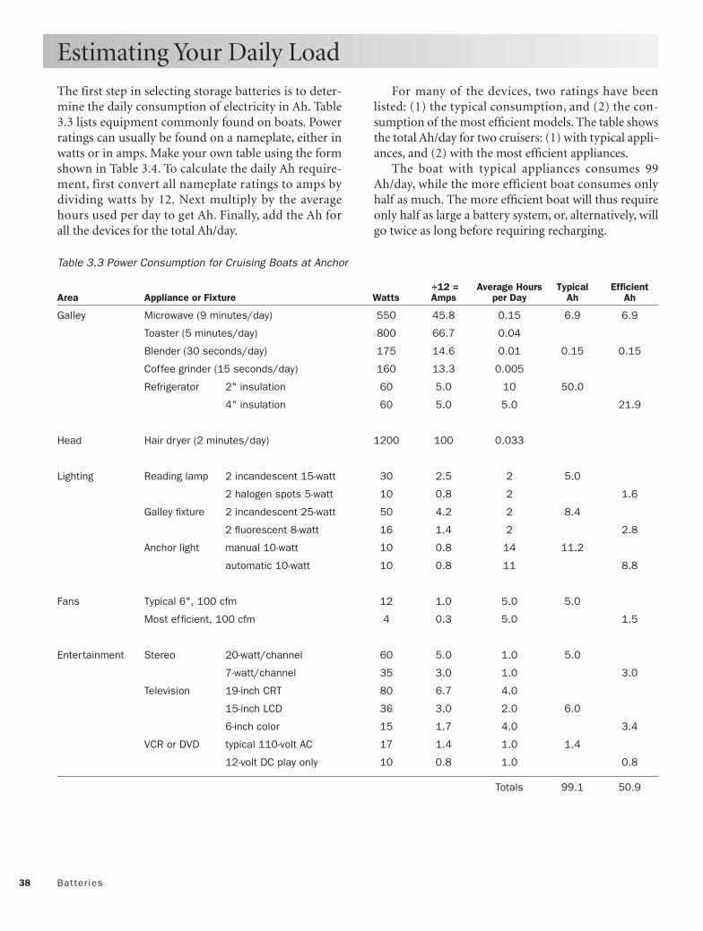
38 Batter ies
The first step in selecting storage batteries is to deter-mine the daily consumption of electricity in Ah. Table3.3 lists equipment commonly found on boats. Powerratings can usually be found on a nameplate, either inwatts or in amps. Make your own table using the formshown in Table 3.4. To calculate the daily Ah require-ment, first convert all nameplate ratings to amps bydividing watts by 12. Next multiply by the averagehours used per day to get Ah. Finally, add the Ah forall the devices for the total Ah/day.
Estimating Your Daily Load
For many of the devices, two ratings have beenlisted: (1) the typical consumption, and (2) the con-sumption of the most efficient models. The table showsthe total Ah/day for two cruisers: (1) with typical appli-ances, and (2) with the most efficient appliances.
The boat with typical appliances consumes 99Ah/day, while the more efficient boat consumes onlyhalf as much. The more efficient boat will thus requireonly half as large a battery system, or, alternatively, willgo twice as long before requiring recharging.
Table 3.3 Power Consumption for Cruising Boats at Anchor
÷12 = Average Hours Typical Efficient Area Appliance or Fixture Watts Amps per Day Ah Ah
Galley Microwave (9 minutes/day) 550 45.8 0.15 6.9 6.9
Toaster (5 minutes/day) 800 66.7 0.04
Blender (30 seconds/day) 175 14.6 0.01 0.15 0.15
Coffee grinder (15 seconds/day) 160 13.3 0.005
Refrigerator 2" insulation 60 5.0 10 50.0
4" insulation 60 5.0 5.0 21.9
Head Hair dryer (2 minutes/day) 1200 100 0.033
Lighting Reading lamp 2 incandescent 15-watt 30 2.5 2 5.0
2 halogen spots 5-watt 10 0.8 2 1.6
Galley fixture 2 incandescent 25-watt 50 4.2 2 8.4
2 fluorescent 8-watt 16 1.4 2 2.8
Anchor light manual 10-watt 10 0.8 14 11.2
automatic 10-watt 10 0.8 11 8.8
Fans Typical 6", 100 cfm 12 1.0 5.0 5.0
Most efficient, 100 cfm 4 0.3 5.0 1.5
Entertainment Stereo 20-watt/channel 60 5.0 1.0 5.0
7-watt/channel 35 3.0 1.0 3.0
Television 19-inch CRT 80 6.7 4.0
15-inch LCD 36 3.0 2.0 6.0
6-inch color 15 1.7 4.0 3.4
VCR or DVD typical 110-volt AC 17 1.4 1.0 1.4
12-volt DC play only 10 0.8 1.0 0.8
Totals 99.1 50.9

39Estimating Your Dai ly Load
Table 3.4 Form for Estimating Power Consumption at Anchor
÷12 = Average Hours Estimated Area Appliance or Fixture Watts Amps per Day Ah
Galley Microwave (9 minutes/day) 550 45.8 0.15 __________
Toaster (5 minutes/day) 800 66.7 0.04 __________
Blender (30 seconds/day) 175 14.6 0.01 __________
Coffee grinder (15 seconds/day) 160 13.3 0.005 __________
Refrigerator 2" insulation 60 5.0 10 __________
4" insulation 60 5.0 5.0 __________
Head Hair dryer (2 minutes/day) 1200 100 0.033 __________
Lighting Reading lamp 2 incandescent 15-watt 30 2.5 2 __________
2 halogen spots 5-watt 10 0.8 2 __________
Galley fixture 2 incandescent 25-watt 50 4.2 2 __________
2 fluorescent 8-watt 16 1.4 2 __________
Anchor light manual 10-watt 10 0.8 14 __________
automatic 10-watt 10 0.8 11 __________
Fans Typical 6", 100 cfm 12 1.0 5.0 __________
Most efficient, 100 cfm 4 0.3 5.0 __________
Entertainment Stereo 20-watt/channel 60 5.0 1.0 __________
7-watt/channel 35 3.0 1.0 __________
Television 19-inch CRT 80 6.7 4.0 __________
15-inch LCD 36 3.0 2.0 __________
6-inch color 15 1.7 4.0 __________
VCR or DVD typical 110-volt AC 17 1.4 1.0 __________
12-volt DC play only 10 0.8 1.0 __________
Other __________
__________
__________
Total

40 Batter ies
Forget the marketing terminology you have seen inbattery advertisements. Batteries can be divided intofour general categories:
1. Conventional, wet-acid automotive starting 2. Deep-cycle, wet-acid 3. Absorbed glass mat4. Gelled electrolyte
Conventional, wet-acid automotive starting batteries areengineered to supply extremely high currents (200 to1,000 amps) for periods of just a few seconds. In spiteof the high current, the duration is so short that theamount of energy drawn (amps × hours, or Ah) issmall. Used in this way, automotive starting batteriesare typically discharged only a few percent of theircapacity before returning to the float state.
The rate at which current can be drawn is propor-tional to plate area, so starting batteries are constructedwith a large number of thin lead plates sandwichedbetween paper or plastic separator plates. When cycleddeeply, battery plate material is shed. Since starting bat-tery plates are so thin to start with, deep cycling willresult in short life.
Don’t be fooled by warranties of 60 or moremonths or names such as “Die-Hard.” While fine forstarting the engine, if used to power your cabin lightsand other house loads, you will be replacing this type ofbattery every season or two. Used only to start theengine, provided they are recharged immediately afteruse, they make a good combination with a large, deep-cycle house battery.
Deep-cycle, wet-acid batteries have fewer but thickerplates designed for regular discharge to 50% or less ofcapacity. The largest users of such batteries are notboats but golf carts and forklifts, which require largecurrents and capacities, in addition to the ability tocycle thousands of times. Such batteries have the max-imum cycling potential and are ideally suited to cruis-ing boats with heavy house loads and long seasons,provided their owners are willing to spend the timemonitoring and maintaining them.
In a well-equipped cruising boat, a deep-cyclehouse bank will also have sufficient cold-crankingcapacity to start the engine. If, as recommended, thehouse batteries are separated into two banks, there islittle need for a dedicated engine-starting battery.
Choosing a Battery Type
Some boaters still carry a small automotive engine-starting battery as a safety backup, however.
Absorbed-glass mat batteries were developed as superiorengine-starting batteries, but are being used more andmore as marine house batteries. They retain all of theirelectrolyte in spongy fiberglass mats and are “sealed”with valve-regulated caps, which recombine charginggases under most conditions. The thin, porous platesthat yield high starting-motor currents do not stand upas well as those of deep-cycle, wet-acid types. How-ever, they can both discharge and recharge at muchhigher rates than wet-acid batteries. Because so manyof these batteries are sold, competitive pricing makesthem attractive. Provided discharge is limited toaround 50%, they are suitable for the seasonal boaterwho expects to replace the batteries every 3 or 4 years.
2 x 10.5"= 21"
12.5"
9"
21"
21"
9"
11"
10"
10"
Size 27
Size 4D
Size 8D
7"
11"
6.6" 6.6"
10.5"
9"
Size 24
Golf cart
12V
6V 6V
12V
12V
12V
Golf cart
Fig. 3.15 Nominal Battery Dimensions

41Choosing a Batter y Type
Gelled-electrolyte batteries were developed for applica-tions where acid spills and gas venting were prohibited,such as military tanks and wheelchairs. Freedom oflocation and from maintenance have made them pop-ular on boats. They cannot be deep cycled as manytimes as wet-acid, deep-cycle batteries, but they are lesssubject to damage if left in a discharged state, andaccept somewhat higher recharge rates. With the caveatthat their lower charging voltages must never beexceeded, gel-cells are suited to boats with large loads,
long seasons, and owners who are totally unwilling tomonitor and maintain their batteries. Before purchas-ing, however, you should seriously consider the AGMbattery, which shares many of the gel’s advantages, yetmay be occasionally and moderately overcharged.
Figure 3.15 shows the nominal sizes of the mostpopular batteries. Actual sizes vary, so assume an extra1⁄2 inch all around, or get actual specifications.
Table 3.5 compares the advantages and disadvan-tages of the four battery types.
Battery Type Advantages Disadvantages
Wet-acid automotive Lowest cost Can’t stand many deep dischargesHigh cranking amps Will be destroyed if left dischargedGood for engine start battery Will spill electrolyte if tipped overSmall, lightweight Relatively short life
Relatively fragile
Wet-acid deep-cycle Less expensive than gels and AGMs Electrolyte level must be monitoredMaximum deep-cycle life (>1,000) Will be destroyed if left discharged too longIndividual cells accessible Will spill electrolyte if tipped overCan be equalized Must be installed uprightWater can be added to electrolyte Battery box should be vented overboard
Extremely heavy
Gelled electrolyte (gel-cell) Very rugged Most expensiveRequires least attention, May be destroyed by overcharging
provided not overcharged Moderate deep-cycle life (500 likely)Can be installed in any positionDoesn’t require ventingWon’t leak even if crackedAccepts high charge rate
Absorbed glass mat (AGM) Most rugged of all High initial costCan be installed in any position Moderate deep-cycle life (250 likely)Doesn’t require ventingWon’t leak unless crackedAccepts highest charge rateTolerates moderate equalization
Table 3.5 Comparing Battery Types

42
Figure 3.16 shows expected lifetime cycles versus depthof discharge under laboratory conditions. The shapeof the curves was established with one set of data eachfor wet-acid, AGM, and gelled-electrolyte batteries. Thegolf cart curve was assumed to be of the same shapeand fitted to the single published 100% discharge point.
A boat is not an ideal environment, so you shouldcount on getting about half of the cycles shown. Thus,instead of 3,000 discharges to 50% for the best wet-acidbattery, you might assume 1,500 cycles. Alternatingbanks daily, and recharging the banks in parallel, youcan project 1,500 recharges × 2 days = 3,000 days, or 8years.
With the same 50% discharge and 2-day cycle, golfcart batteries should last about 5 years, AGMs 4 years,and gelled electrolyte batteries 2 to 3 years.
Figure 3.17 plots cost per kilowatt-hour versusdepth of discharge assuming half of the life cyclesshown in Figure 3.16. It was assumed the batteries were
Optimum Depth of Discharge
size 8D (220 Ah) and were bought for list price, less15%. The costs (2005) assumed were: wet-acid $544,AGM $444, and gelled $308. The equivalent pair of 6-volt golf cart batteries cost $180.
Figure 3.17 leads to two conclusions:
1. Considering the cost of the batteries alone, theoptimum depth of discharge is approximately50%.
2. Due to a lower purchase cost, the golf cart batteryis the most economical battery.
Charging CutoffFigure 3.14 showed that charging current should bereduced once a battery has been recharged to 75% ofcapacity. Stopping at 75%, however, results in sulfation.If the engine is run only for charging, run timebecomes uneconomical beyond 85 to 90%. Whencharging underway or with wind or solar, run time isnot an issue, and recharge to above 90% is desirable.
We will assume a boat at anchor, a discharge limit of30 to 50%, and a recharge cutoff of 85 to 90%. Since abattery is usually considered “dead” when it has perma-nently lost 40% of its rated capacity, we will also de-rate our batteries by 20%.
Example: Our daily load is 75 Ah. We decide to dis-charge to 30% of capacity and charge to 85%. Therequired (derated to 80%) battery size is then
75 Ah/0.80(0.85 – 0.30) = 170 Ah
Once you have estimated your daily load and cho-sen your charge-discharge range, Figure 3.18 allowseasy determination of the required battery size.
Depth of Discharge, % 0 20 40 60 80 100
Bat
tery
Life
Cyc
les
(K=
1,00
0)
0K
2K
4K
6K
8K
Golf cart (6V)
Best wet cells
Typical AGM
Typical gelled
Fig. 3.16 Expected Charge/Discharge Cycles
Depth of Discharge, % 0 20 40 60 80 100
0.00
0.20
0.40
0.60
0.80
1.00
Golf cart (6V)
Best wet cells
Gelled
AGM
Cos
t of B
atte
ries,
$/k
Wh
Fig. 3.17 Lifetime Costs per kWh of Battery Types
Nom
inal
Bat
tery
Cap
acity
, Ah
300
400
500
200
100
Load, Ah/day50250 75 100 125 150
0
(30 – 85)%(40 – 85)%(50 – 85)%
(60
– 85
)%
Example
Fig. 3.18 Battery Size Selector
Batter ies

43Siz ing the Alternator
After a deep discharge, batteries will accept very highrates of charge. AGM and gelled-electrolyte batteriestypically accept up to 0.5C (50% of capacity per hour),while healthy wet-acid batteries safely accept up to0.25C. Once a battery has been recharged to 75% ofits capacity, the charging rate must be reduced in orderto prevent gassing in all batteries, as was shown in Fig-ure 3.14.
The total cost per kilowatt-hour produced andstored is the sum of battery cost (Figure 3.17) and en-gine/fuel costs. Figure 3.19 compares battery andengine/fuel costs. Engine/fuel costs assume:
• Consumption = 0.5 gallon per hour • Fuel price = $2.20 per gallon • Engine life = 10,000 hours • Engine price = $7,000 • Maintenance = $0.20 per hour
The three curves show the dramatic savings that canbe realized by matching the alternator to its load. Min-imum engine/fuel cost is achieved by deep dischargeof AGM or gelled-electrolyte batteries and recharge at0.5C (220 A for the example of paralleled 8D batteries).For a pair of 8D wet-acid batteries, the matched alter-nator would be rated at 110 A.
Solar and wind power will be discussed in Chapter10, but costs per kilowatt-hour for solar and wind-pro-duced power have been included in Figure 3.19 forcomparison. The solar system is assumed to cost $480per 60-watt panel, last 10 years, and be used all year inMiami. The wind machine has a 5-foot blade, costs$1,500, lasts 10 years, and is used all year in 10-knotaverage winds.
Solar and wind costs per kilowatt-hour are indepen-dent of discharge depth, assuming the systems arematched to the daily load. It is interesting to note thattypical utility rates are $0.10 to $0.15 per kilowatt-hour.
Sizing the AlternatorB
atte
ry a
nd C
harg
ing
Cos
ts, $
/kW
h
Depth of Discharge, % 0 20 40 60 80 100
0.00
1.00
2.00
3.00
4.00
220-amp alternator
Charging two 8D batteries(440 Ah) to 85% using:
0.50
1.50
2.50
3.50
Wind
10 30 50 70 90
Solar
110-amp alternator
55-amp alternator
BATTERY COSTS:
ENGINE COSTS:
ALTERNATEENERGYCOSTS: Golf cart (6V)
Best wet cells
GelledAGM
Fig. 3.19 Total Costs per kWh of Generated Power

44 Batter ies
A battery bank consists of one or more batteries, con-nected to act as a single 12-volt unit. Two commonquestions are: (1) should a large bank consist of onevery large battery, two smaller 12-volt batteries in par-allel, or two 6-volt batteries in series; and (2) assumingtwo banks, should both be on all the time, or shouldthey be alternated?
First, how large a bank do you need? Some say thatyour battery capacity can never be too large, but con-sider two facts:
1. Batteries should not be left in even a partiallydischarged condition any longer than necessary.
2. The cost of charging batteries is greater than theamortized cost of any battery, and unless a bat-tery is discharged at least to 50%, recharging cur-rents are restricted and charge times elongated.
These are both reasons to size each battery bank fora single day’s load. If your daily load is less than about100 Ah, you can get by with a single 4D battery (185Ah) by cycling between 85% and 30%. The problem—unless you are young and a weight lifter—is the weightof such a large battery. As you can see from Table 3.1,4D batteries typically weigh 125 pounds, while 8Dsweigh in at around 160 pounds. The option is to breakthe bank into smaller, more manageable, units.
Here are arguments for the single battery, the seriesconnection, and the parallel connection (Figure 3.20).
A single battery is better:• Because there is just one case, you get the maximum
Ah in a given space.• Two battery cables and terminals are eliminated.
Parallel connection of smaller batteries is better:• Assuming isolation diodes (page 58) are used, the
bad battery can be removed, and the remaining bat-tery still has full voltage at half capacity.
• The stronger battery cannot drive a weaker batteryinto cell reversal.
Series connection of 6-volt batteries is better:• Failure of a single cell will be apparent as a sudden 2-
volt drop, but voltage will still be sufficient for enginestarting.
• Failure of a single cell in one battery will not drawdown the voltage in a paralleled battery.
• 6-volt golf cart batteries are the cheapest sources ofbattery power.
Series vs. Parallel
The second question was whether, in the case of twobattery banks, to leave the battery selector switch per-manently in the “Both” position.
Reasons “Both” is better:• Current drain from each battery is less, so less energy
is lost to internal resistance. This is important whenusing an electric windlass or a microwave oven.
• Each battery receives only half of the charge currents,so both batteries can be charged in half of the time. Ifusing solar or wind, charging near 100% capacitywill less likely cause gassing.
Reasons alternating banks are better:• A catastrophic short circuit, or leaving the anchor
light on for a week, will not result in total loss ofcapacity. The reason for two banks is redundancy.
• Without an expensive Ah meter, battery health canbe accurately assessed only after a 24-hour restperiod. Switching banks allows better monitoring ofcapacity and performance.
Recommendation: alternate banks daily, but switchto “Both” when charging with the engine, starting theengine, hauling the anchor with an electric windlass, orrunning other high loads, such as microwave ovens.
SingleRolls 4D
12V, 185Ah
+
–12V
185AH122 lb
Series2 Deka 8G6V200
12V, 180Ah
+
– –
+6V
180AH72 lb
6V180AH72 lb
Parallel2 Rolls Size 27
12V, 180Ah ––++12V
90AH62 lb
12V90AH62 lb
Fig. 3.20 Battery Size Selector

Building a Battery BoxBuilding a battery box is an excellent way to learn basicfiberglass techniques. No curved surfaces are required,appearance is not critical, and the plywood core forms themold.
Figure 3.21 shows the construction of a box largeenough to hold two 12-volt D4s (330 Ah total) or four 6-volt T-105 golf cart batteries (440 Ah total).
Batteries weigh about 0.75 pound and contain 2ounces of acid per Ah. While you are making the box, con-sider the consequences of 330 pounds of batteries and 28quarts of battery acid breaking loose in a storm. Also pic-ture installing or removing batteries weighing up to 165pounds each.
1. Mark cuts on 3⁄4-inch AC-Exterior plywood.2. Apply a layer of fiberglass to both sides of the
uncut plywood using epoxy or polyester resin.3. Cut the panels and apply resin to edges.4. Glue and nail the box together.5. Sand round all outside edges and fill inside corners
with an epoxy paste.6. Apply at least three overlapping strips of fiberglass
reinforced plastic (FRP) cloth at each inside andoutside corner, making sure there are no voids.
7. Apply two complete layers of fiberglass cloth overthe entire outside and finish with epoxy paint.
8. Fasten the box firmly to the hull with countersunkstainless steel, flat-head (SS FH) bolts.
9. Apply two additional layers of fiberglass cloth tothe inside and finish with white epoxy paint.
10. Drill a vent hole near the top of the side most con-venient to venting. The hole diameter should pro-vide a press fit for a length of garden hose.
11. lnsert batteries using 1⁄4-inch nylon line, leaving theline for later extraction.
12. Fasten the cover down and run the vent hose to apoint outside the hull.
45Batter y Boxes
There are three good reasons to house batteries insturdy covered battery boxes: (1) to capture and ventoverboard explosive hydrogen gas generated in the caseof overcharging, (2) to contain electrolyte that may bespilled in rough seas, and (3) to prevent metal tools and
other objects from accidently shorting the battery ter-minals.
Battery boxes can be purchased in a few sizes ready-made, or you can construct one to custom fit yourbank. Making your own has the advantage of fittingboth the space and the batteries better.
Battery Boxes
Fig. 3.21 DIY Battery Box
Cover (1)
Bottom (1)
Shortside (2)
Longside (2)
23.5"
20.5
"
19"
22"
23.5" 19"
12"
12"
All sides 3/4"exterior plywood
Round all corners
Fill with epoxy paste
3 layers FRP inside& outside corners
2 layers FRP overall inside surfaces
SS FH machinescrews (FRP over) for securing
Vent holeNylon web straps (2)
Cover locating pins
Fits D4sor
Golf cart
Min. distance to fuelsystem or component
(see USCG regulations)
12"

46 Batter ies
Adapted from ABYC Standard E-10, Standards andRecommended Practices for Small Craft, dated Decem-ber, 1996. ABYC standards conform with Title 33, Codeof Federal Regulations, Part 183—Boats and Equipment.
E-10.6. Battery Capacitya. Cranking batteries shall have at least the cold crank-ing performance rating (CCA @ 32°F) or marinecranking performance rating (MCA @ 32°F) amper-age required by the engine manufacturer.
b. Accessory batteries and cranking batteries used asaccessory batteries shall have a rated reserve capacity inminutes determined by the calculations in ABYC E-11,DC Electrical Systems Under 50 Volts.
E-10.7. Installationa. Batteries shall be secured against shifting.
b. An installed battery shall not move more than oneinch in any direction when a pulling force of ninetypounds or twice the battery weight, whichever is less,is applied through the center of gravity of the battery asfollows:
(1) Vertically for a duration of one minute.(2) Horizontally and parallel to the boat’s center
line for a duration of one minute fore and oneminute aft.
(3) Horizontally and perpendicular to the boat’scenter line for a duration of one minute to star-board and one minute to port.
c. To prevent accidental contact of the ungroundedbattery terminal to ground, each battery shall be pro-tected so that metallic objects cannot come into contactwith the ungrounded battery terminal. This may beaccomplished by means such as:
(1) Covering the ungrounded terminal with a bootor nonconductive shield.
(2) Installing the battery in a covered battery box, or (3) Installing the battery in a compartment spe-
cially designed only for the battery(ies).
d. Each metallic fuel line and fuel system componentwithin twelve inches and above the horizontal plane ofthe battery top surface as installed shall be shieldedwith dielectric material to protect against accidentalshort-circuiting.
ABYC Standards for Batteries
NOTES: 1. Terminal insulation or battery covers do not complywith this requirement since during installation orremoval of a battery, these protective devices are usuallyremoved in order to connect the cables.2. Any nonconductive material may be used for shieldingas long as it is durable enough to withstand accidentalcontact by a tool or the battery terminals during servic-ing, installation or removal.
e. Each battery shall not be installed directly above orbelow a fuel tank, fuel filter, or fitting in a fuel line.
NOTE: This does not prohibit a battery from beinginstalled directly above or below an uninterrupted fuelline; however, if this fuel line is within the twelve inchenvelope of the top surface of the battery it shall beshielded dielectrically as required in ABYC E-10.7.d.
f. A vent system or other means shall be provided topermit the discharge from the boat of hydrogen gasreleased by the battery. Battery boxes whose coverforms a pocket over the battery shall be vented.
NOTE: These provisions also apply to installations ofsealed batteries.
g. If the mounting surfaces or components of the boatin the immediate vicinity of the battery location are ofa material attacked by the electrolyte, a mountingmeans shall be provided that is made of a material thatis not damaged by electrolyte.
h. Fasteners for the attachment of battery boxes or traysshall be isolated from areas intended to collect spilledelectrolyte.
E-10.8. Wiringa. Connectors to battery terminals shall be made withfitted connectors providing secure mechanical andelectrical connections. Spring clips or other temporaryclamps shall not be used.
b. A soldered connection that joins a battery terminalconnector to a conductor may be used if the length ofthe soldered joint is at least 1.5 times the diameter ofthe stranded portion of the battery conductor.
c. Battery supply conductors must be sized to satisfythe load calculations as outlined in ABYC E-11.10. [SeeChapter 6.]

This page intentionally left blank

Alternators
48
CHAPTER 4
GNDF
+GNDF
+– +–
+–
Copyright © 1993, 2006 by Charlie Wing. Click here for terms of use.

49
An alternator is a rotary current machine thattransforms mechanical rotation into AC cur-rent. The AC current produced by the alterna-
tor coils is rectified by diodes into DC current forcharging the ship’s batteries.
In order not to overcharge the batteries we need aregulator for controlling the alternator. Whether theregulator field-coil wire is connected to the positive orto the negative battery terminal determines whether itis a type-P or type-N alternator. The methods of pow-ering the voltage regulator and supplying excitationcurrent to the field coil vary as well.
Regulator bypass controls, allowing more rapid bat-tery charging, are popular among cruisers, the mostsophisticated of all being the Link 2000-R Charge Controller.
The electrical demands of boats vary widely, so avariety of charging setups have evolved, from the sim-plest one alternator/one battery of the day boater to themultiple alternators/multiple batteries of the dedicatedliveaboard cruiser.
Since most engines are equipped with light-dutyalternators, cruisers and liveaboards having large bat-tery banks very often upgrade to higher-output mod-els, requiring guidance on alternator installation.
Despite the great number of alternator models andcharging setups, the basic principles and componentsare largely the same, allowing for simple troubleshoot-ing procedures.

50 Alternators
If you had fun making the galley battery in Chapter 3,try making the galley alternator in Figure 4.1. All youneed are an analog voltmeter or ammeter (a multime-ter with many ranges is best), a large steel nail or bolt,several feet of insulated copper wire, and a magnet.
Wrap a dozen turns of the wire around the nail andconnect the bare ends to the meter. If you are using amultimeter, start with the highest amps scale. Hold themagnet as close to the head of the nail as possible with-out actually touching it. Now move the magnet rapidlyback and forth, as shown in the illustration. The nee-dle of the meter should jump back and forth acrosszero.
If the needle doesn’t move, switch the meter to alower scale. If the needle still doesn’t move, increase thenumber of turns of wire until it does move.
What’s going on? As Hans Oersted discovered in1820, an electric current is induced in a wire wheneverthe magnetic field around the wire changes. Our mov-ing magnet induces magnetism in the nail. As the per-manent magnet moves back and forth, the magnetismin the nail alternates in direction, so the magnetic fieldthrough the coiled wire alternates as well. The alter-nating field produces pulses of current of alternatingpolarity as shown in the graph at the bottom of Figure4.1.
The scale of the graph is not important to ourexperiment, but you should know that the current isdirectly proportional to the strength of the magneticfield, the rapidity of the magnet motion, and the num-ber of turns in the coil.
Simple Two-Pole MagnetInstead of passing the magnet back and forth across thehead of the nail, we can make a rotating machine to do the same thing. Figure 4.2 shows a straight bar magnet pivoted about its center between two series-connected coils. The coils are wound in opposite direc-tions, so that the opposite poles of the magnet producecurrent in the same direction. As the magnet turns,however, each coil sees alternating poles, so the cur-rent changes polarity as shown in the graph.
This type of current is called alternating current,or AC. Chapters 7 through 9 of this book deal with ACpower on boats. All we need to know about AC at thispoint is that both voltage and current reverse, usuallymany times per second. One complete swing from plus
A Galley Alternator
to minus and back to plus again is called a cycle. Thenumber of cycles per second is the frequency, measuredin Hertz (Hz). Utility power in the United States isdelivered at 60 Hertz; in Europe, at 50 Hertz.
- +
Am
ps
0
+
-
N
S
One Cycle
Fig. 4.2 A Rotary Current Machine
- +N S
Am
ps
0
+
-
Fig. 4.1 A Galley Alternator
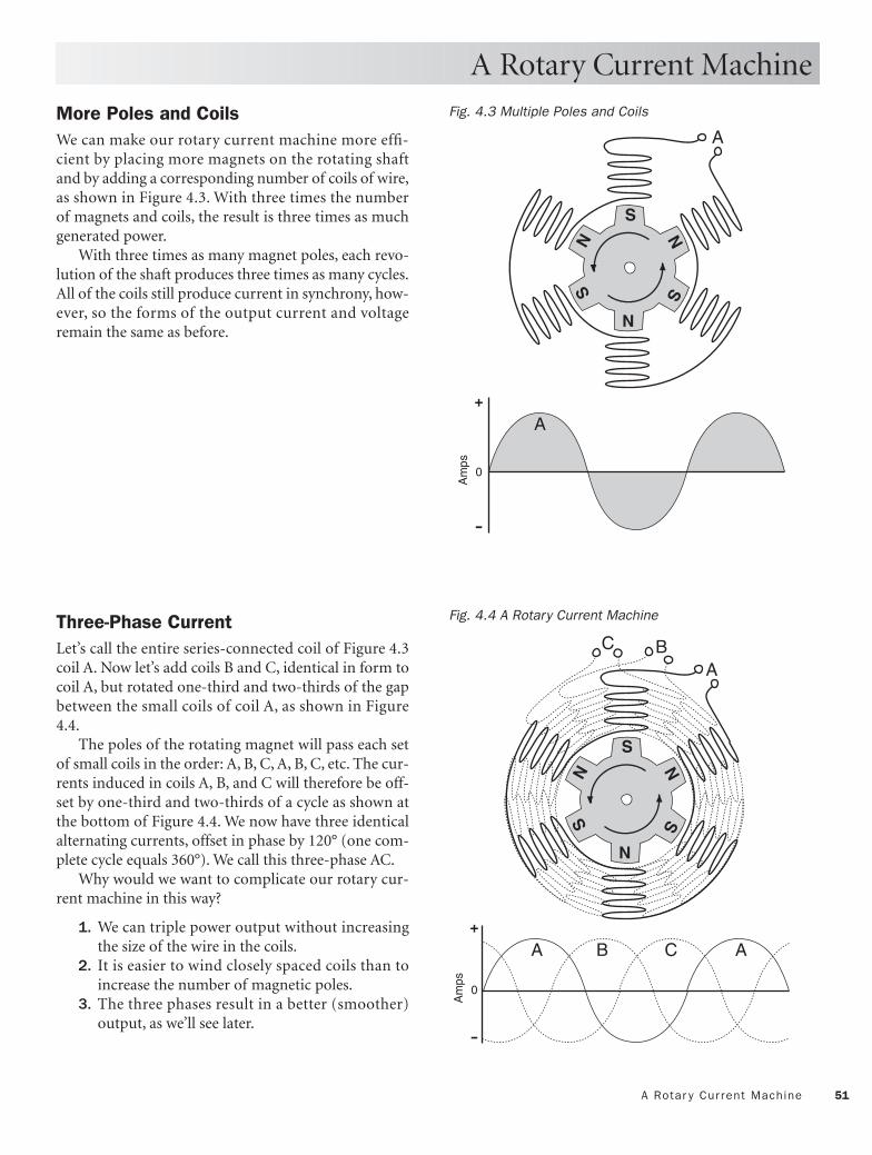
51A Rotar y Cur rent Machine
More Poles and CoilsWe can make our rotary current machine more effi-cient by placing more magnets on the rotating shaftand by adding a corresponding number of coils of wire,as shown in Figure 4.3. With three times the numberof magnets and coils, the result is three times as muchgenerated power.
With three times as many magnet poles, each revo-lution of the shaft produces three times as many cycles.All of the coils still produce current in synchrony, how-ever, so the forms of the output current and voltageremain the same as before.
Three-Phase CurrentLet’s call the entire series-connected coil of Figure 4.3coil A. Now let’s add coils B and C, identical in form tocoil A, but rotated one-third and two-thirds of the gapbetween the small coils of coil A, as shown in Figure4.4.
The poles of the rotating magnet will pass each setof small coils in the order: A, B, C, A, B, C, etc. The cur-rents induced in coils A, B, and C will therefore be off-set by one-third and two-thirds of a cycle as shown atthe bottom of Figure 4.4. We now have three identicalalternating currents, offset in phase by 120° (one com-plete cycle equals 360°). We call this three-phase AC.
Why would we want to complicate our rotary cur-rent machine in this way?
1. We can triple power output without increasingthe size of the wire in the coils.
2. It is easier to wind closely spaced coils than toincrease the number of magnetic poles.
3. The three phases result in a better (smoother)output, as we’ll see later.
A Rotary Current Machine
Am
ps0
+
-
A
N
S
N
S
NS
A
Fig. 4.3 Multiple Poles and Coils
Am
ps
0
+
-
ABC
N
S
N
S
NS
A B C A
Fig. 4.4 A Rotary Current Machine

52 Alternators
As we saw in Chapter 3, batteries produce direct cur-rent (DC), which is always of the same polarity. Torecharge batteries we need DC. The rotary currentmachine is of no use unless we convert its three-phaseAC output to DC.
Enter the diode. As its circuit symbol (Figure 4.5,top) indicates, the diode allows current to flow only inthe direction of the arrow. If you like analogies, you canthink of a diode as the equivalent of a check valve in awater-supply system, allowing water to flow in onedirection but not the opposite.
All diodes have the following three ratings:
maximum forward current—maximum current inthe forward direction peak inverse voltage—maximum voltage at whichdiode will block current flow in reverse direction forward voltage drop—voltage in the direction of thearrow at which diode begins to conduct current
Diodes come in different sizes and shapes, depend-ing on their intended uses. Tiny signal diodes areintended for low-current applications. Large rectifyingdiodes are used in high-current applications such asalternators. A typical alternator diode might have rat-ings of 50 amps, 50 volts, and 0.6 volt.
If you haven’t yet put away your galley experiment,insert a diode into the circuit as shown in Figure 4.6.Now when you pass the magnet back and forth, theneedle should deflect only in the positive direction. Ifyou get a negative deflection, either the meter leads arereversed, or the diode is pointing in the wrong direc-tion. As the current plot shows, the magnet and wirecoil are still producing negative pulses, but the pulsesare blocked by the diode.
Figure 4.7 shows how a diode would similarly blocknegative current in our rotary current machine. Theprocess of passing current of one polarity but block-ing current of the opposite polarity is called rectifica-tion. Passing only the positive halves of an AC wave iscalled half-wave rectification.
Rectification would be twice as efficient if we couldpass both halves of the AC wave. This is accomplished
Rectification
+ –
Signal diode Power rectifier diode
Diode symbol
Fig. 4.5 Diodes and the Diode Symbol
- +N S
Am
ps
0
+
-
+ -
Passed by diode
Blocked by diode
Fig. 4.6 The Galley Alternator with Rectifier
Am
ps
0
+
-
A
N
S
N
S
NS
APassedby diode
Blockedby diode
Fig. 4.7 Half-Wave Rectification

53Rect ificat ion
with a four-diode full-wave rectifier (Figure 4.8). Nomatter the polarity of current and voltage through thewire coil, there are always two of the four diodes seeingreverse voltage and acting as if they were open circuits.
Follow the currents in Figure 4.9 as they flowthrough the coil, the diodes of the rectifier, and theexternally connected load in the alternating closed cir-cuits labeled Path 1 and Path 2.
The first half-wave travels Path 1: from the coil,
through diode 1, into the positive terminal, through theexternal load, into the negative terminal, through diode3, and back to the coil.
The second half-wave travels Path 2: from the coil,through diode 2, out the positive terminal, through theexternal load, into the negative terminal, through diode4, and back to the coil.
An obvious extension would be to provide each ofthe coils in Figure 4.4 with their own full-wave recti-fiers, as shown in Figure 4.10. This would be fine if wedesired three separate outputs to recharge three sepa-rate batteries or to power three independent DC cir-cuits, but we don’t. We’d rather have a single DC sys-tem, and, although we might have three batteries, we’drather charge them in parallel from a single source.
It would be needless torture to force you throughthe logic, but it turns out that connecting the ends ofthe three coils produces a felicitous simplification.
Am
ps
0
+
-
A
N
S
NS
N
S
-
+
Fig. 4.8 Full-Wave Rectification
ABCN
S
N
S
NS
-
+
-
+
-
+
Am
ps 0
+
-
BA C BA C BA C
Fig. 4.10 Three Full-Wave Rectifiers
-
+
1 2
4 3
Load
-
+
1 2
4 3
Load
PATH 1 PATH 2
Fig. 4.9 Rectifier Current Paths

54 Alternators
Figure 4.11 shows the two common ways to connectthe coils: the Delta and the Y. With the coils connected,half of the twelve diodes can be eliminated. With eitherconfiguration, we are left with only three coil terminals,each of which is connected to a diode pair.
Rectification
Figure 4.12 shows the ends of the coils connected toa single pair of output terminals. The currents combinein such a way that total output current approximatessteady DC. Our rotary current machine has finallyevolved into a DC-output alternator.
-+
DELTAConfiguration
YConfiguration
A B
C
A B
C
-
+-
+
- +
-
+-
+A
mps
0
+ A B C A B C A B C
A B
C
-
+
A B
C
-
+
Am
ps
0
+ A B C A B C A B C
Fig. 4.11 Delta and Y Coil Arrangements Fig. 4.12 Delta and Y Connections in a Real Alternator

55Control l ing the Alternator
As you will recall, the output of the galley alternator inFigure 4.1 depended on three variables:
1. Strength of the magnet 2. Number of turns of wire 3. Speed of magnet movement
The alternators in Figure 4.12 are similar. We canvary their outputs only by changing engine rpm, whichis inconvenient.
The problem of control in a real alternator is solvedby varying the strength of the magnet. Instead of thepermanent magnet in Figure 4.1, we use an electro-magnet as in Figure 4.13. The iron core concentratesthe magnetic field, which is generated by a currentthrough the coil. The strength of the field generated isproportional to the current flowing in the field coil.Thus, alternator output can be controlled by varyingcurrent through the field coil.
Figure 4.13 also demonstrates a phenomenon youcan verify with your galley magnet and two or morenails: A magnet will induce magnetism of oppositepolarity in a second piece of iron in close proximity.For example, in Figure 4.13, two additional iron barsplaced at the ends of the core also become magnets.This can be verified with either iron filings or a smallcompass.
Figure 4.14 shows the added iron bars replaced byiron disks with fingers that have been bent around andinterleaved. In this way, current through a single fieldcoil wrapped around the shaft results in alternatingmagnetic fingers around the circumference. It alsoshows how current can be fed to the field coil throughcarbon brushes riding on copper slip rings fixed to theshaft.
Figure 4.15 shows a typical alternator rotor with itsinterleaving magnetic poles, slip rings, and field coilwrapped around the inside shaft. This rotor assemblyrotates inside the collection of stationary coils, knownas the stator.
The device that controls field-coil current, and thusalternator output, is known as the voltage regulator.How it came to be known as a voltage—rather than acurrent—regulator, is lost in history. We will notchange its name. Just remember that it controls out-put current, not voltage.
Controlling the Alternator
N
S S
S
N
N
NS
S
N
Field coil
Fig. 4.13 Electromagnets
S
Slip rings
N
N S
N
N S
N
S
S
Fieldcoil
Carbon brushes
Fig. 4.14 Alternator Rotor and Brushes
N
N
N
S
S
Fig. 4.15 Typical Alternator Rotor

56 Alternators
Voltage RegulatorsWe’ll start with the old-fashioned electromechanicalvoltage regulator still found in some older boats (Fig-ure 4.16). The field current flows through the relay armthat pivots about F and contacts the points labeled“Ignition” and “Ground.”“Ignition” is connected to thebattery + terminal through the engine ignition switch.
The relay arm is held up against the ignition contactby the adjusting spring. With full field current flow-ing, the alternator quickly produces its maximum cur-rent. If the battery voltage is low enough, the alterna-tor continues to pump out maximum current. Whenbattery voltage rises to a set value (between 13.8 and14.2 volts), the increased current flowing from igni-tion to ground through the relay coil pulls the armdown and opens the contact. Field current drops tozero, alternator output drops to zero, battery voltagedrops, and the relay arm is pulled up to the ignitioncontact to start the cycle again.
The greater the voltage of the battery, the greater thepercentage of time the contact remains pulled downinto the open position. Alternator output switchesbetween full and zero output hundreds of times persecond. The average voltage approaches a constant,while average charging current falls toward zero (pluswhatever load is being drawn at the same time). Batteryvoltage is adjusted by turning the adjusting spring.
It is easy to check a voltage regulator. With theengine running, and after output current has droppedto a trickle, turn on a heavy load. If the regulator isworking, voltage will remain the same, but alternatorcurrent will increase by the amount of the added load.
Electromechanical regulators have been replaced bysolid-state regulators. Although they can be destroyedby reversing battery and ground leads and by excessiveheat, they never wear out. Figure 4.17 shows a solid-state equivalent of the electromechanical regulator.
The operation of a solid-state regulator is easilyunderstood once you understand how a transistorworks. Figure 4.18 shows the most common type oftransistor—the NPN. It has three leads: base (B), emit-ter (E), and collector (C). It can be thought of as anamplifying valve. The current flowing into the basecontrols the current flowing from the collector to theemitter. Because the junction between base and emitteris essentially a diode in the direction of the arrow, nocurrent flows until the base-to-emitter voltage reachesabout 0.5 volt. Above that voltage, the output current is20 to 100 times the base current. Thus the transistorcan be used as an electronic switch or current amplifier.
Controlling the Alternator
Ignition orBattery +
Fieldcoil
F
Ground
Relaycoil
Relay arm
Adjust
Fig. 4.16 Older Electromechanical Voltage Regulator
Base (B)
Collector (C)
Emitter (E)
Basecurrent
Collectorto emittercurrent
Fig. 4.18 How an NPN Transistor Works
Ignition or auxiliary
Adjust
Fieldcoil
F
Gnd
Batteryor +
2
31
Fig. 4.17 Solid-State (Transistorized) Voltage Regulator

57Type-P and Type-N Alternators
In Figure 4.17 assume the battery voltage is low. Thebase of transistor 1 is therefore at a low voltage andtransistor 1 is off. With transistor 1 acting as a highresistance between the base of transistor 2 and ground,the voltage of transistor 2 base is high and transistor 2is on. Transistor 3 amplifies the collector-to-emittercurrent of transistor 2 by twenty times or more, caus-ing a large current through the field coil and maximumalternator output.
Soon battery voltage increases, however, and tran-sistor 1 switches on. The resistance from the base oftransistor 2 to ground decreases, and transistors 2 and3 switch off, cutting off the current to the field coil.With no field current, alternator output ceases.
The transistors switch on and off hundreds of timesper second, with the ratio of on-to-off times control-ling the average field current and alternator-outputcurrent. The analogy between electromechanical andsolid-state voltage regulators is obvious.
Note that the solid-state regulator of Figure 4.17had two positive terminals:
1. Battery, or +, is for sensing the voltage of the bat-tery so that it can be charged at the correct volt-age.
2. Ignition, or auxiliary, supplies the field current.
Not to be confused with NPN and PNP transistors,alternators and regulators can be connected in two dif-ferent ways called type-P and type-N (Figure 4.19).
In type-P alternators and regulators, the regulator isconnected to the positive end of the field coil. In type-N alternators, the voltage regulator is located betweenthe negative end of the field coil and ground.
Both type-P and type-N voltage regulators drawpower from the battery + terminal. If the power is notinterrupted when the engine stops, the voltage regulator/alternator coil will slowly drain the battery.
Figure 4.20 shows three small diodes (the diodetrio) connected to the three coil terminals in a type-Nalternator. These diodes feed a terminal labeled “Aux.”When the alternator is not turning, there is no currentto power the regulator, so there is no drain on the bat-tery. Reverse current flow from the battery to the aux-iliary terminal is prevented by the charge diodes.
Figure 4.21 shows a second method of supplyingregulator current. A large isolation diode is placedbetween the three charge diodes and the alternator +output terminal. This isolation diode prevents reversecurrent flow from the battery to the regulator.
Type-P and Type-N Alternators
Voltageregulator
F
Gnd
Voltageregulator
F
Gnd
Field coil(in alternator)
Field coil(in alternator)
TYPE P
TYPE N
Battery +Battery +
Fig. 4.19 Type-P and Type-N Regulators
Isolationdiode
A B
C
-
+
Fieldcoil
toReg
Aux
F
Fig. 4.21 Isolation Diode
A B
C
-
+
Fieldcoil
toReg
Diodetrio
Aux
F
Fig. 4.20 Diode Trio

58 Alternators
Battery Isolation DiodesDo not confuse the diode trio or the alternator isola-tion diode with battery isolation diodes. The first twoare internal parts of the alternator and will not be seenunless the case is opened. If a boat has battery isola-tion diodes (Figure 4.22) they will appear as largediodes mounted on a finned heat sink. Their purpose,if present, is to prevent paralleled batteries from dis-charging each other. Not all marine systems have bat-tery isolation diodes.
Exciting the Alternator Did you spot a problem with the circuits of Figures4.20 and 4.21? If we actually wired an alternator andregulator as shown in either of the figures, the alterna-tor would never come on. An alternator will not gen-erate an output current without an input field current,but there will be no field current until there is an alter-nator output! To solve this chicken-or-egg dilemma,alternators that derive their field currents from inter-nal-diode trios or isolation diodes require a tempo-rary source of field current called the excite current.
Figure 4.23 shows a typical excite circuit added tothe alternator of Figure 4.21. Its operation will befamiliar to anyone who owns an automobile.
When the ignition switch is turned on, currentflows from the battery, through the lamp and paralleledresistor, to the alternator auxiliary terminal, and thenthrough the field coil. As soon as the engine starts,however, the alternator begins generating current,which then makes the voltage at the auxiliary terminal0.5 to 1.0 volt higher than the battery voltage. Withonly 0.5 to 1.0 volt across its terminals, the 12-voltcharge-indicator lamp goes out. If it stays on or comeson again, you know that the alternator in not produc-ing current. A resistor is placed in parallel with thelamp in order to provide excite current in case the lampfilament burns out.
An alternate and common solution is to feed thecharge indicator lamp from the engine oil-pressureswitch rather than the ignition switch, so that the alter-nator is excited as soon as oil pressure climbs. Anadvantage of this system is keeping the load on theengine low until it is up to speed.
Powering the Voltage Regulator
+IsolatorIsolator
To alternator
+ Battery 2-+ Battery 1
-
+
–
Ignitionswitch
Chargelight
R
Isolationdiode
A B
C
Fieldcoil
toReg
Aux
F
+ Battery-
Fig. 4.22 Battery Isolation Diodes
Fig. 4.23 A Common Alternator Excite Circuit

59Regulator Bypass Controls
Alternators with fixed-voltage regulation are not idealfor boats. Without modification, they are simply cur-rent-limited, fixed-voltage chargers set at compromisevoltages between 13.8 and 14.2 volts. As we saw inChapter 3, 13.8 to 14.2 volts is higher than the recom-mended float voltage and lower than the recommendedfast-charge absorption voltage. An alternator con-trolled by a standard regulator will never fully charge abattery in typical operation, yet will overcharge if runfor days on end.
Cruising boats, particularly sailboats, impose largeloads on their batteries but run their engines only a fewhours per day. Worse, when a boat is at anchor theengine is usually run for the sole purpose of chargingthe batteries. We need a way to control the alternatoroutput for optimally fast charging (Figure 4.24).
Figure 4.25 shows regulator bypasses installedacross both type-P and type-N voltage regulators. Notethat the original voltage regulators remain in place. Thebypass regulators simply control field current in orderto control alternator output. After the regulator bypasshas accomplished its task and is switched off, the orig-inal voltage regulator resumes control.
Some regulator bypasses are manual, requiring dili-gent monitoring of battery-charge current and voltage.The simplest automatic bypasses come on when theengine is started, provide a constant-current bulkcharge, then switch off when the battery reaches a pre-set voltage. More sophisticated regulator bypasses (seenext page) automatically cycle through bulk, absorp-tion, and float stages every time the engine is started.An equalization charge can also be selected whendesired.
Before discussing the most sophisticated regulators(charge controllers), Figure 4.26 shows a simple man-ual-control regulator bypass you can build yourself.Note that the bypass circuit is the same whether usedwith a type-P or type-N alternator. The on/off switchallows the bypass to be switched into or out of the cir-cuit. The 2-ohm, 25-watt fixed resistor limits the max-imum field current. The 20-ohm, 100-watt rheostat(variable power resistor) allows the field current to bevaried over a wide range.
Warning! Manual regulator bypasses should neverbe used without diligent monitoring of both batterycharging current and voltage. It is easy to destroy a$300 battery with a $30 homemade regulator bypass.If you do not have the discipline to continuously mon-itor the charging process, you should either forgo thefast-charge option or invest in one of the sophisticatedautomatic models.
Regulator Bypass Controls
Bulkcycle
Absorptioncycle
Floatcycle
12.0
13.0
14.0
15.0
Cha
rgin
g V
olta
ge V=14.4
Constant 13.5V
90%80%
I=25%C
Time
Fig. 4.24 Example of Optimally Fast Charging
Type PVoltage
regulator
F
Gnd
+
Voltageregulator
F
+
Fieldcoil
Fieldcoil
Gnd
Regulatorbypass
Regulatorbypass
Type NVoltage
regulator
Fig. 4.25 Regulator Bypass Hookups
Type PVoltage
regulator
F
Gnd
+
Fieldcoil
2Ω25W
20Ω100W
On/Off
Regulatorbypass
2Ω25W
20Ω100W
On/Off
Type NVoltage
regulator
F
Fieldcoil
Gnd
Regulatorbypass
+
Fig. 4.26 A Manual Regulator Bypass

The Xantrex Link 2000-R Charge Controller (Figure4.27) is a dedicated computer that monitors and con-trols both an inverter/charger (any of the Xantrex Free-dom series) and an alternator. Parameters monitoredinclude:
• battery voltage• amps being drawn• amp-hours withdrawn• amp-hours remaining• time remaining to discharge• number of battery charges When either inverter or engine is turned on, the
2000-R initiates the four-cycle optimum charge rou-tine: charge, acceptance, float, and equalize (Figure4.28).
Either one or two battery banks may be monitoredand controlled. Voltages for the four charge cycles aretailored both to the type of battery and to the real-timetemperature of the battery (Table 4.1). Thus, the charg-
Link 2000-R Charge Controller
ing routine is truly ideal for any given battery type andconditions.
Charging OperationThe status of the four-step charging process is indi-cated by the horizontal row of LEDs at the bottom ofthe control panel (Figure 4.27 again).
Charge cycle (red LED ON). After a 2-second engine-start delay, the field current is ramped up over 20 sec-onds until the alternator reaches its full output. Charg-ing at full current continues until either battery bankreaches the acceptance voltage.
Acceptance cycle (orange LED ON). Charging contin-ues at the fixed acceptance voltage until charging cur-rent drops to 2% of the battery nominal capacity. Atthis point the regulator goes into an acceptance-holdstatus during which the acceptance voltage is main-tained and the charging current is monitored. If voltageand current remain steady for 10 minutes, or if voltageholds steady but current rises during 20 minutes, theregulator goes into the float stage. If, however, batteryvoltage drops to below the acceptance voltage for 2minutes, the entire charge cycle is restarted.
Float cycle (green LED ON). Battery voltage is main-tained at the float voltage. The alternator supplies cur-rent up to its full output in order to supply currentdraw and maintain the float voltage. If battery voltagedrops to below the float voltage for 2 minutes, thecharge cycle is restarted.
Equalize cycle (red LED FLASHING). This is initiatedmanually by pressing a combination of buttons. Chargecurrent is held at a constant 4% of capacity while volt-age increases to 16.0 volts (or the acceptance voltage forgelled batteries). Equalization terminates in 3.5 hoursor when charging current drops to 2% of capacity at16.0 volts.
Table 4.1 Voltage Settings for the Link 2000-R
Type 0 Type 1 Type 2 Type 3Temp. Wet-Cell Gel-Cell 1 Gel-Cell 2 AGM
°F Accept Float Accept Float Accept Float Accept Float
120 12.5 12.5 13.0 13.0 13.0 13.0 12.9 12.9110 13.6 12.7 13.5 13.0 14.0 13.4 13.9 12.9100 13.8 12.9 13.7 13.2 14.1 13.5 14.0 13.090 14.0 13.1 13.8 13.3 14.2 13.6 14.1 13.180 14.2 13.3 14.0 13.5 14.3 13.7 14.2 13.270 14.4 13.5 14.1 13.6 14.4 13.8 14.3 13.360 14.6 13.7 14.3 13.8 14.5 13.9 14.4 13.450 14.8 13.9 14.4 13.9 14.6 14.0 14.5 13.540 15.0 14.1 14.6 14.1 14.7 14.1 14.6 13.630 15.2 14.3 14.7 14.2 14.8 14.2 14.7 13.7
Link 2000-RC o n t r o l B a t t e r y
T i m e
1Reset A hrs
2Data
Function
F l o a tAcceptChargeA C I nStatus:
Batt CapCharged %Charged V
∆ Equalize
Pwr Share
Idle Mode
A h r sA m p sVo l t s
Invert
Charger
S e t u p
Fig. 4.27 Link 2000-R Charge Controller Panel
Charge Acceptance Float
12.0
13.0
14.0
15.0
16.0
Cha
rgin
g V
olta
ge
Constant 14.4V
Constant 13.5V
Full Curre
nt
Equali
ze
Time
Fig. 4.28 Four-Cycle Charging for a Wet-Cell Battery at 70°F
60 Alternators

61Charging Setups
No battery/alternator setup is ideal for every vessel.Cost is a big issue for most boaters, but pattern of useand degree of vulnerability when dead in the water arealso considerations. Here are a variety of setups, fromamong dozens, demonstrating the possibilities and theissues involved. Note that bilge pumps (and any otherdevice that must never be shut off) are wired and fuseddirectly to a battery.
Figure 4.29 shows the most common configuration insmall recreational boats. All electrical loads except thebilge pump are disconnected from the battery with thesimple ON/OFF switch.
Regardless of setup, an important consideration isthat the alternator-to-battery + connection must neverbe broken while the alternator is generating current.Otherwise the energy stored in the alternator’s induc-tive coils would produce a large voltage spike, possiblydestroying both the alternator rectifier diodes and anyconnected electronics. Three solutions are a voltagesnubber from alternator output to ground, a warningsign on the switch, and, in the case of a four-poleswitch, a built-in field disconnect.
Figure 4.30 shows a common configuration in smallcruising boats. Here two batteries are charged from thesame alternator. Depending on the position of thefour-pole switch, the charge can be directed to eitherbattery or both batteries at the same time. Similarly, thedischarge can be from either or both.
The batteries may be of unequal size—a small startbattery and a large house battery—but they must be ofthe same type. If one were a gel and the other a wet-acid, for example, either the gel would be overchargedand destroyed, or the wet-acid would be underchargedwith the same long-term result.
Figure 4.31 shows a setup where the alternator is per-manently connected to the house battery, so there isno danger of damage from interrupting the alternatoroutput. As shown the starting battery can be charged inparallel with the house battery with the switch in the“Both” position.
If, instead, the alternator were wired directly to the“Common” terminal of the switch, the setup would bethe same as in Figure 4.30, with the attendant danger ofinterrupting the alternator output.
Charging Setups
GNDF
+GNDF
1
OFF
C
+-
Battery 1
To starter
To bilge pump
To panel
GNDF
+GNDF
1
B 2
OFF
C
+-
Battery 1
+-
Battery 2
To starter
To panel
To bilge pump
1
B 2
OFF
CGND
F
+GNDF
+-
House
+-
Starting
To starterTo panel
To bilge pump
Fig. 4.29 Simplest One-Battery System
Fig. 4.30 Simplest Two-Battery System
Fig. 4.31 Two Batteries with Alternator Protected

62 Alternators
Figure 4.32 shows a pair of isolation diodes. The diodesmake it possible to leave both batteries connecteddirectly to the alternator output without the danger ofone battery draining the other. Because the diodes looklike closed circuits in the forward direction, they alsosolve the open-alternator problem.
The big problem with isolation diodes is that theydrop the voltage from alternator to battery by 0.6 to 1.0volt, requiring the voltage regulator to be adjustedupward by the same amount to compensate.
Most boaters are not aware of the voltage drop, sotheir batteries are chronically, severely underchargedand suffer early demise.
Figure 4.33 shows a setup incorporating a series regula-tor. When house and starting batteries are of differentsize or type, one of the batteries will end up over-charged while the other is undercharged, shorteningthe lives of both.
A series regulator, such as Ample Power’s Elimina-tor, is designed to solve this problem. The alternator’sregulator is set up for the optimum charging of thehouse battery. At the same time the series regulator, setup for the characteristics of the starting battery,siphons some of the charging current to charge it.
The parallel switch can be used either to bypass theseries regulator or to combine the battery outputs.
Figure 4.34 shows one way to charge two batteries fromtwo alternators. This is useful both when the batteriesare of different size and/or different type and when thebatteries are larger than can be charged quickly from asingle alternator. It also provides redundancyin case one of the alternators fails.
Commonly the starting battery is chargedby the engine’s original alternator, and a high-output alternator with multistep regulator isadded to charge the much larger house bank.
Charging Setups
OFF
1
2
C
GNDF
+GNDF
+- +-
Starting
To starter
To bilgepump
To panel
House
GNDF
+GNDF GND
F+GND
F
+-
Battery 1
+-
Battery 2
1
OFF
C
2
OFF
C
Topanel
Tostarter(s)
Parallelingswitch
To bilgepump
Fig. 4.32 Batteries Isolated with Diodes
Fig. 4.34 Two Batteries and Two Alternators
GNDF
+GNDF
+-
House
+-
Starting
Topanel
Tostarter
Isolationswitch
Parallelswitch
SeriesRegulator
To bilge pump
Fig. 4.33 System with Series Regulator

63Alternator Instal lat ion
When changing alternators there are four critical phys-ical considerations: (1) mounting configuration, (2)pulley alignment, (3) belt size, and (4) belt tension.
Figure 4.35 illustrates four Balmar mounting con-figurations designed to be compatible with mostmarine engines. Most often a combination of washers,spacers, and bushings can compensate for an imper-fect fit.
Figure 4.36 shows how to bring the alternator pul-ley into alignment with the engine drive pulley. Hold astraightedge against the faces of the two pulleys, andshim the alternator foot (or feet) with washers until thefaces are in the same plane.
Alternators of up to 80 amps output can use 3⁄8-inchbelts (width of outside belt face), up to 110 amps 1⁄2-inch belts, and over 110 amps dual belts.
Proper belt tension can be determined in two ways:
1. Turn the alternator pulley retaining nut with awrench. If the belt slips it is too loose.
2. Press on the belt with moderate force (Figure4.37). Deflection should be between 1⁄4 inch and5⁄16 inch.
Alternator Installation
6.7"
1"
Single 1" Foot (Model 71)
6.7"
2"
Single 2" Foot (Model 712)
6.7"
.5".5" 3.15"
Dual Foot 3.15" ID
(Model 70)
7.6"
Dual Foot 4" ID
(Model 95)
.6".6" 4"
Fig. 4.35 Mounting Configurations (Balmar)
Fig. 4.36 Aligning Engine and Alternator Pulleys
Fig. 4.37 Testing Belt Tension
Belt Deflection1/4" to 5/16"
ENGINE
Straightedgeagainst faceof pulley
Misalignment

64 Alternators
When an engine fails to turn over or batteries go flat,the fault may be in the batteries, the alternator, anexternal voltage regular, or the wiring. Troubleshooting
Troubleshooting
the charging/starting system is made easier if youunderstand how each of the components work, so readChapters 3 and 4 before using the charts and proce-dures that follow.
NO
YES
NO
YES
NO
YES
NO
YES
NO
YES
NO
YES
NO
YES
NO
YES
Is voltage at battery >12 volts? Battery dead or discharged
Is voltage at input terminal of battery switch >12 volts?
Defective + (red) battery cable
Battery switch OFF or defective
Defective conductor to ignition switch or blown engine fuse
Defective key switch or push-button switch
Defective conductor from ignition switch
0 volts = defective solenoid;low voltage = low battery or terminal corrosion
Engine seized or water in cylinder
Is voltage at common terminal of battery switch >12 volts?
Is voltage at input to ignition switch 12 volts?
Is there >10 volts at output terminal of ignition switch with ignition key on and start button depressed?
Is there >10 volts at solenoid input with ignition key on and start button depressed?
With compression released, can you turn engine over using wrench on crankshaft nut?
Is there >10 volts at starter input with ignition key on and start button depressed?
Starter motor defective or jammed
Troubleshooting 1: Engine Won’t Turn Over

65
Trou
ble
sh
oo
ting
NO
NO
NO
NO
NO
NO
NO
YES
YES
YES
YES
YES
YES
YES
Defective alternator.
You have solved the problem.
Turn off all circuits and set battery switch to tested battery. Disconnect cable from battery + terminal. Measure resistance from cable end to battery – terminal.Is reading > 100 ohms?
Leakage current is draining battery. Repeat test, discon-necting circuits one at a time to find leak.
Reconnect battery cable. Start engineand bring to 1,200 rpm. Measure voltage between battery terminals.Is voltage < 13.0 volts?
Alternator OK.Turn on all lighting circuits.Is voltage now < 13.0 volts?
Alternator not charging.Is alternator belt tight?.
Are there > 2.0 volts at the voltage regulator field terminal?.
Increase (if external) voltage regulator setting. Does charging voltage increase?
With engine running, measure voltage between alternator B+ terminal and battery + terminal. Is voltage < 0.3 volt?.
Tighten or replace
Broken field wire or oil pressure switch.
Corrosion in charging cabor engine ground connec
Run engine 2 hours. Is voltage now > 14.0 vol
Diminished battery capacEqualize or replace batte
YES
NO
NO
Troubleshooting 2: Batteries Not Charging Fully
NO
YES
Corrosion in charging cable or engine ground connection.
Run engine 2 hours. Is voltage now > 14.0 volts?
Diminished battery capacity. Equalize or replace battery.
Voltage regulator set too low. Adjust or replace.

66 Alternators
Troubleshooting 3: The AlternatorVariations in appearance, arrangement of terminals,and internal connections number in the hundreds. Itis beyond the scope of this book to detail the differ-ences, but an alternator is an alternator, and, whateverits name, it works on the principles above.
There are two basic approaches to alternator repair.The first is to carry replacements for the componentsmost likely to fail in the field: charge diodes, diode trio,isolation diode, brushes, bearings, and voltage regula-tor. The second is to carry an exact replacement for theentire alternator, including the voltage regulator ifexternal. I favor the second approach for the followingreasons:
Troubleshooting
1. There will be no spare part you might have over-looked. For example, what if the problem were abroken mounting flange?
2. You don’t have to carry special tools such as abearing puller, press, or heavy-duty solderingiron.
3. Replacement takes minutes; repair takes hours.4. The cost of the whole alternator (with trade-in)
is probably no greater than the cost of a com-plete set of spare components.
The following troubleshooting guide should helpyou to discover whether the problem is with the wiring,the alternator, or the regulator.
STEP 1.
Turn the engine off and the battery-select switch off.The multimeter should read:
• Battery + to Ground, 12 V or more • Alternator + to Ground, 0 V
If Alternator + to Ground reads 12 V, suspect a shortedisolation diode.
STEP 2.
Turn the engine on with the battery-select switch on.The multimeter should read:
• Alternator + to Battery +, 0.5 to 1.0 V • Battery + to Ground, about 1 V higher than with
the engine off
If not, suspect the isolation diode feeding the battery.
STEP 3.
To check a battery isolation diode definitively, discon-nect it from the batteries and read resistance across thediode, reversing leads.
• An open-circuit diode reads ∞ both directions• A shorted diode reads near 0 both directions • A healthy diode reads near ∞ in one direction
and 0 in the other direction
GNDF
+GNDF
+-
+-
– +
V
Check the Wiring from Alternator to a Battery with Battery Isolation Diodes
Fig. 4.38 Wiring with Isolation Diodes

67Troubleshooting
STEP 1.
Turn the engine off and turn the battery-select switchto the battery being tested (repeat tests for other batter-ies). On the voltage scale the multimeter should read:
• Battery + to Ground, 12 to 13 V. If not, the bat-tery may be bad.
• Alternator + to Ground, 12 to 13 V. If not, Alterna-tor + to Battery + cable is bad.
STEP 2.
Turn the engine on and turn the battery-select switchto the battery being tested (repeat tests for other batter-ies). On the voltage scale the multimeter should read:
• Battery + to Ground, about 1 V higher than withthe engine off.
• Alternator + to Ground, at least 1 V higher thanwith the engine off. If not, the alternator is notcharging.
GNDF
+GNDF
+– +–
+-
STEP 1.
Turn the engine off and the battery-select switch on.The multimeter should read:
• Alternator + to Battery +, 0 V • Alternator – to Battery –, 0 V
On the resistance scale the multimeter should read:• Alternator + to Battery +, 0 • Alternator – to Battery –, 0
If not, suspect corrosion or a broken wire.
STEP 2.
Turn the engine on and the battery-select switch on.The multimeter should read:
• Alternator + to Battery +, < 0.5 V • Alternator – to Battery –, < 0.5 V
If not, suspect corrosion or a broken wire.
GNDF
+GNDF
– +
V
- +
Check Wiring from an Alternator to a Battery with No Battery Isolation Diodes
Check Alternator and Battery Voltage with No Battery Isolation Diodes
Fig. 4.39 Wiring with No Isolation Diodes
Fig. 4.40 Alternator and Battery Voltage

68 Alternators
Troubleshooting
STEP 1.
Turn the engine off and turn the battery-select switchto the battery being tested (repeat tests for other bat-teries). On the voltage scale the multimeter shouldread:
• Battery + to Ground, 12 to 13 V. If not, the bat-tery may be bad.
• Alternator + to Ground, 0 V. If not, suspect ashorted isolation diode.
STEP 2.
Turn the engine on and turn the battery-select switchto the battery being tested (repeat tests for other batter-ies). On the voltage scale the multimeter should read:
• Battery + to Ground should be about 1 V higherthan with the engine off. If not, the alternator isnot charging.
• Alternator + to Ground should be 0.5 to 1.0 Vhigher than Battery + to Ground. If not, suspect ashorted isolation diode.
– +
V– +
V
GNDF
+GNDF
+-
+-
STEP 1.
Turn the engine off, measure the voltage from Battery +to Ground, and note its value.
STEP 2.
Remove the wire from Alternator Terminal F.
STEP 3.
Connect a test light (minimum 12 W, such as an anchorlight) from Terminal F to Ground.
STEP 4.
Start the engine and measure the voltage from Battery+ to Ground again. If the voltage is about 1 V higherthan it was when the engine was off, then the alternatoris OK, but its regulator is bad.
GNDF
+GNDF
– +
+ -
A
Check Alternator and Battery Voltage with Battery Isolation Diodes
Check a Type-N Alternator with No Output
Fig. 4.41 Voltages with Isolation Diodes
Fig. 4.42 Checking a Type-N Alternator

69Troubleshooting
If the type-P regulator tested bad above, the problemmay lie not in the regulator but in its excite circuit. Totest the excite circuit:
STEP 1.
Start the engine.
STEP 2.
Measure the voltage from Battery + to Ground.
STEP 3.
Momentarily connect the test light between Battery +and Alternator Terminal F. If the voltage from Battery +to Ground is now about 1 V higher than with theengine off, the alternator and regulator are OK, but theexcite circuit is bad.
You can either repair the excite circuit, or you cancreate an excite circuit temporarily by placing a 12 Wlamp between the engine oil-pressure switch and Alter-nator Terminal F.
GNDF
+GNDF
-+
Voltageregulator
–
+F
GNDF
+GNDF
– +
+ -
A
STEP 1.
Turn the engine off, measure the voltage from Battery +to Ground, and note its value.
STEP 2.
Remove the wire from Alternator Terminal F.
STEP 3.
Connect a test light (minimum 12 W, such as an anchorlight) from Terminal F to Battery +.
STEP 4.
Start the engine and measure the voltage from Battery+ to Ground again. If the voltage is about 1 V higherthan with the engine off, then the alternator is OK, butits regulator is bad (see next test).
Check a Type-P Alternator with No Output
Check the Excite Circuit for a Type-P Alternator Regulator
Fig. 4.43 Checking a Type-P Alternator
Fig. 4.44 Flashing a Type-P Alternator

Bonding
70
CHAPTER 5
DCV ACV mAΩ
+–
Referenceelectrode
Proposed zinc
Copyright © 1993, 2006 by Charlie Wing. Click here for terms of use.

71
Bonding is a somewhat controversial, and oftenpoorly understood, wiring practice. As usual, westart by answering a basic question—what is
bonding?The purposes of bonding are threefold: (1) electrical
system grounding, (2) lightning protection, and (3)corrosion protection.
The bonding controversy stems from the possibilityof its encouraging stray-current corrosion. So—tobond, or not to bond—that is the question we addressin detail.
Fortunately, there are simple methods for testingyour protection against corrosion. These, and theABYC standards for the general application of cathodicprotection, should protect your boat’s underwater met-als.
Though neither caused nor prevented by bonding,other types of corrosion are explained as well.

72 Bonding
No marine wiring topic causes more confusion thanbonding. That is because there are at least three sepa-rate and compelling reasons for electrically connecting,or bonding, metal objects aboard a boat:
1. Electrical system grounding 2. Lightning protection 3. Corrosion protection
At the same time, there are reasons for not bondingcertain items. As they occur, these exceptions will bediscussed. Note that the grounding of AC systems iscovered separately in Chapter 9, AC Standards andPractices. You will find there, however, that AC ground-ing is related to DC grounding in a simple way.
Grounded, Grounding, BondingIdeally, ground is the voltage of the water in which theboat is immersed. Unfortunately, voltage in the watermay vary slightly due to stray electrical currents. As wewill see, one of the purposes of the bonding system is toforce the voltage of and within the hull to be as uni-form as possible through the use of low-resistance con-ductors and connections.
As defined by the ABYC and shown in Figure 5.1:• Grounded conductors are the current-carrying con-
ductors that connect to the side of the source(almost universally the battery negative terminal),which is intentionally maintained at groundpotential.
• Grounding conductors are normally non-current-carrying conductors, provided to connect theexposed metal enclosures of electric equipmentto ground, the primary function of which is tominimize shock hazard to personnel.
• Bonding conductors are normally non-current-carrying conductors used to connect the non-current-carrying metal parts of a boat and thenon-current-carrying parts of direct-currentdevices on the boat to the boat’s bonding system.
All DC electrical devices receive their powerthrough a pair of positive and negative input terminals,served by a pair of conductors. Current flows into thepositive terminal from a positive conductor (wire)from the DC distribution panel and, ultimately, fromthe positive (+12 V) terminal of the battery. Ideally,the same amount of current returns to the battery neg-ative terminal through the grounded conductor. All
What Is Bonding?
grounded conductors are held to the same voltage(ground, or zero volts) by being connected to the DCnegative bus and, ultimately, to the battery negative ter-minal.
So that people are not accidently exposed to livevoltage from a piece of equipment shorted to a livewire, the metal enclosures of all electrical equipmentare connected to ground by grounding conductors.These conductors are in addition to the grounded con-ductors and carry current only in the case of an elec-trical fault.
Bonding conductors are also separate from, and inaddition to, the grounded conductors. As elaboratedlater in this chapter, they play important roles in bothlightning and corrosion protection. They should takeas short and direct routes as possible to the substantialcommon-bonding conductor, which usually runs nearthe fore-and-aft centerline of the boat. Each bondingconductor should be at least as large as the current-car-rying positive and negative conductors that serve theequipment.
The engine-bonding conductor should be at least aslarge as the largest bonding conductor in the rest ofthe bonding system and large enough to carry startingcurrent. Twin engines with crossover starting systemsshould be bonded to each other, as well, with a conduc-tor large enough to carry the starting current.
The large common-bonding conductor should bebare or green. If wire, it may consist of bare, stranded,tinned copper or insulated stranded wire of minimumsize 8 AWG. If solid, it may be uninsulated copper,bronze strip, or copper pipe at least 0.030 inch thickand 0.5 inch wide. The copper, bronze strip, or pipemay be drilled and tapped, provided it is thick enoughto provide at least three full threads for terminalscrews, or it may be unthreaded for machine screwsand locknuts.
Equipment to be bonded includes: engines andtransmissions, propellers and shafts, metal cases ofmotors, generators and pumps, metal cabinets andcontrol boxes, electronics cabinets, metal fuel and watertanks, fuel-fill fittings, electrical fuel pumps and valves,metal battery boxes, metal conduit or armoring, andlarge nonelectrical metal objects as recommended inthe Lightning Protection section.
Note that you may choose not to bond electricallyisolated through-hull fittings, as will be discussed fur-ther in the Corrosion Protection section.

73What Is Bonding?
+ –
Windlass
+– Wiper
Overcurrentprotection
Blower
Bilge pump
Float switch
Float switch
Grounding conductorGrounding conductor
Groundedconductors
Engine Engine
Batteryswitch
DC mainnegative
bus
Accessorynegative
bus
DC negative bus
Parallel switchor solenoid
AC grounding bus
Batteryswitch
+–
Fuel tankFill Gauge
Electronicsground plate
Immersed lightning ground plate or strip
Lightning down conductor(from lightning mast)
Large metal objects
Chainplates
Enginenegativeterminals
Seawater strainer
Seacock
++
–
+
–
–
Fuel tank
Housebattery
Startbattery
Startbattery
Horn
Sacrificial zinc
Grounding bus Bondingconductors
Grounding ANDbonding conductor
FillGauge
Distribution Panel
Main feedOvercurrentprotection
+–
+–
FORCORROSIONPROTECTION FOR
LIGHTNINGPROTECTION
FORSYSTEM
GROUNDING
Fig. 5.1 Typical DC Negative System and DC Grounding System (Adapted from ABYC Standard E-11, Figure 18)

74 Bonding
At any moment, there are approximately 2,000 light-ning storms in progress around the earth, producing100 strikes every second. In some regions lightning isa rarity. In others it is an almost daily occurrence.
To put the danger in perspective, there are approxi-mately 24,000 lightning deaths per year in the world,100 in the United States. From 1959 to 2003, recordeddeaths in the United States included:
• Florida 425 • Texas 195• North Carolina 181• Ohio 136 • New York 134 • Tennessee 133 Where the deaths occurred:• In or around the home 20% • In vehicles (mostly open) 19% • Taking refuge under trees 15% • In boats 13% • Everywhere else 33% Considering the significant percentage of deaths
occurring in boats and the low number of people inboats at any given time, it is apparent that the poten-tial for lightning strikes on boats is a serious matter. Infact, the ABYC devotes all of Standard E-4 to the matterof lightning protection.
What Is Lightning and How Does It Act? In all lightning theories, a combination of verticallymoving water droplets and air currents results in thebuildup of large quantities of oppositely charged par-ticles within clouds and between clouds and theground (Figure 5.2). The electrical potential differencesbetween charges may be as high as 100,000,000 volts.By comparison, the voltage on the power lines runningalong a street is a mere 12,000 volts.
In particular, the base of a cloud becomes negativelycharged. Since opposite charges attract, the surface ofthe earth directly beneath the cloud becomes positivelycharged. People standing in this positively charged areaunder a cloud sometimes report feeling their hairstanding on end due to the static charge just before alightning strike. What initially prevents the chargesfrom combining is the extreme electrical resistance ofair. Some scientists believe that lightning strikes aretriggered by cosmic rays knocking electrons from airmolecules. The freed electrons accelerate in the volt-age field, causing the release of more electrons and ion-izing the air.
Lightning Protection
Ionization proceeds in steps of about 100 feet. Elec-trons flow downward through the ionized path andcause a faint blue-white glow, similar to the flow ofelectrons in the ionized gas of a neon sign. Each steprequires only about 0.00005 second to ionize and fill, sothat the stepped leader traverses a distance of 10,000feet, from the base of a cloud to ground, in about 0.005second.
The final step to ground is of most interest to aboater. Up to the last step, the presence of a boat hasno influence on either the location or the direction ofthe discharge. When looking for that final connectionto earth, however, the lightning will head for the closestaccumulation of positive charge. That generally meansthe highest point within a radius of 100 feet. If thatpoint is you, chances are you will be struck. If it is thetip of your mast, your mast will be struck.
After the ionization of the column has been com-pleted by the leader, there exists a short circuit fromcloud to earth. The resulting rush of accumulatedcharge from cloud to earth is what we see as the light-ning bolt—an ionized column of air, heated to50,000°F, conducting a typical current of 50,000 amps.The resulting rapid heating of the air produces a super-sonic air-pressure wave heard as thunder. The entire0.005-second process may be repeated several or evendozens of times during the following second, depend-ing on the initial size of the accumulated charge.
Direct strikes are the most dangerous. Consider thatthe largest circuit breaker or fuse on your boat is prob-ably rated at less than 100 amps, and that the cranking
+ ++
+ +++
+ ++
+++
+
– – – – – – – –– – – – – – – –– – – – – – – –
+ + + + + + + + + +
+ +
Fig. 5.2 Discharge of Cloud Charge

75Lightning Protect ion
current to your starter motor is probably on the orderof 200 amps. Now consider what 50,000 to 200,000amps might do to that same wiring. Although the peakcurrent lasts only 0.0001 second, the resistive heatingis often sufficient to burn insulation, melt components,even vaporize conductors.
Much lightning damage occurs from near-hits,however. It is not uncommon for one boat to suffer adirect strike and for boats in adjacent slips to lose elec-tronic equipment. Just as a current-carrying wire pro-duces a magnetic field, and a varying magnetic fieldproduces current in a conductor (the principle behindthe alternator), lightning currents produce extrememagnetic fields, which then induce currents in nearbywires. These induced currents are often sufficient todestroy sensitive electronic circuits.
Just any copper conductor will not suffice to con-duct currents of 50,000 amps. The conductor must belarge and conductive enough to present the path ofleast resistance to ground (the surrounding water, inthe case of a boat). Small-diameter wire, corroded con-nections, and too small a ground plate (area of metal incontact with the water) may cause the lightning to seekadditional paths to ground, resulting in dangerous sideflashes. The recommendations in ABYC Standard E-4are intended to minimize both danger and damagefrom lightning.
Zones of Protection Metal masts tend to draw the final step of a leader tothemselves within a radius equal to their height. Theconical zone beneath the tip is known as the zone ofprotection. A person or object entirely within this zoneis substantially protected from a direct strike.
Figure 5.3 shows zones of protection for a power-boat with a lightning-protective mast and with themast extended by a grounded air terminal. Powerboathulls do not generally fall entirely within their zonesof protection unless either their masts are extended bygrounded antennas or outriggers, or they have morethan one grounded mast.
Figure 5.4 shows the zone of protection for a sail-boat mast less than 50 feet. A sailboat hull will usuallylie entirely within the zone of protection. To qualify asa lightning-protective mast, the mast must either bemetal or be equipped with an air terminal and metalconductor to ground (see Figure 5.6).
Figure 5.5 shows the zone of protection for a boatwith a lightning-protective mast more than 50 feet.With more than one mast, zones are drawn for eachmast. The combined protective zone includes all areasunder one or more of the individual zones. To qualifyas lightning protective, each mast must be grounded.Multihulls require grounding plates in each hull.
H1H2
H1H2
H1H2
Solid antenna
Lightning mast
Protected zone with solid antennaextending the height of the lightningmast to protect nearly the entire boat
Protected zone withlightning mast only
Fig. 5.3 Lightning-Protective Zone for Motorboat with Lightning-Protective Mast or Mast with Approved Extension

76 Bonding
Lightning Protection
HH
H
100ft 10
0ft
Masts more than50 ft (15 m)
Zone for taller mast Zone for shorter mast
Fig. 5.4 Lightning-Protective Zone for Sailboat Mast Less Than 50 Feet
Fig. 5.5 Lightning-Protective Zone for Sailboat Mast Over 50 Feet or More Than One Mast

77Lightning Protect ion
The Safe Path to Ground Regardless of any lightning rod or charge dissipator, ifyour mast is the highest object in the vicinity it will bestruck. The purpose of the safe path to ground is toprovide a path to ground (the water) as short, straight,and conductive as possible to prevent side flashes toalternate routes. The path consists of two parts: thelightning-protective mast and the lightning-ground con-nection.
Lightning-Protective Mast
Metal masts qualify as protective masts. If nonconduc-tive, however, a mast must be provided with a ground-ing conductor running from an air terminal 6 inchesabove the mast in as straight a line as possible to thelightning-ground connection. The conductor must besecurely fastened to the mast and consist of either astranded-copper wire of minimum size 4 AWG or ametal strip of conductivity equal to that of 4 AWG cop-per wire and thickness of at least 0.030 inch.
Joints, including that to the lightning-ground con-nection, must not be subject to immersion. In the caseof 4 AWG wire, the connection must be strong enoughto support a 45-pound weight for 1 minute. To avoidcorrosion, all bolts, nuts, washers, and lugs must be gal-vanically compatible with the conductor.
A stainless steel radio antenna may serve as an airterminal provided it has either a means for direct connection to ground, or a lightning-protective gap(closely spaced electrodes, which lightning will easilyjump). If not disconnected when the antenna isgrounded, the antenna feed line should also have alightning arrestor, or transient voltage surge suppres-sor.
Lightning-Ground Connection
A lightning-ground connection may be any underwa-ter metal surface of at least 1-square-foot area. Metalhulls, centerboards, and external (not encased in fiber-glass) keels are excellent. Although metal rudders qual-ify in area, the connection from mast to rudder is toolong.
Where the lightning-ground connection is animmersed ground plate at the base of the mast, thebackstay and other large aft metal objects, because ofthe distance, should be grounded to the engine insteadof the ground plate.
It is commonly believed that the large surface areasof the propeller and shaft provide adequate lightninggrounding. While true, relying on the conductivity of
the engine, transmission, and shaft may lead toextremely large currents through main-engine- andtransmission-output bearings, to their detriment. If theshaft and propeller are to be bonded, it should bethrough a brush riding on the shaft.
Sintered bronze plates, intended to serve as groundplates for SSB radios, are questionable as lightninggrounds. Due to their porosity, these plates do havewetted areas greater than the areas of their envelopes,but evidence suggests that they are not significantlymore effective than plain copper plate of the same area.In fact, it is theorized that edge length is more impor-tant than area in lightning ground plates. A 12 foot by 1inch by 1⁄4 inch copper strip would be six times moreeffective than a 1 foot by 1 foot square copper plate.
In order, the best lightning-ground connections are:
1. Metal hull 2. External metal keel (attach to keel bolts) 3. External 12 foot by 1 inch by 1⁄4 inch copper
strip 4. Large sintered bronze plate
Air terminal
Parallel pathParallel path
Bondingconductors(6 AWG)
EngineMetal tank
Immersedground plateor strip (1 sq. ft.)
4 AWG conductorshort as possible with8" min. radius bends
Primarylightningconductor(4 AWG)
Secondarylightningconductor(6 AWG)
Fig. 5.6 The Safe Path to Ground

78 Bonding
Protecting Electronics A well-protected boat may lose electronics. The prob-lem is that today’s solid-state electronics are very intol-erant of voltage surges. It doesn’t matter whether thesurge comes from a direct lightning hit or from currentinduced in the antenna, microphone, or power leads bythe magnetic field pulse of a nearby strike.
Two basic approaches to protecting electronics are:(1) shorting the surges, and (2) disconnecting all theleads.
Shorting the Surges
Figure 5.7 shows an antenna at the top of the mast. Fora solid-wire antenna with base-loading coil to be aneffective air terminal, there must be a lightning-bypassgap between the solid wire and the base of the antenna.If not, the inductive base coil resists the lightning cur-rent, and the lightning-protective mast originates at thebase of the antenna. If the antenna is fiberglass with aless than 8 AWG conductor, its conductivity is insuffi-cient, and the lightning protection again originates atthe top of the mast.
A coaxial conductor from antenna to radio can pickup current, either as part of a direct strike, or inducedby the magnetic field of a nearby strike. This surge isshorted to ground by a transient voltage surge suppres-sor (TVSS) several feet from the electronics enclosure.
Surges on the power supply line are shorted toground by a metal oxide varistor (MOV), which typi-cally acts in less than 1 microsecond. Both TVSS andMOV devices are available at ham- and marine-radiodealers.
There remain several problems with the approach:
1. Insertion of the TVSS in the antenna-feed lineresults in some loss of transmitted power.
2. By shorting the cable to ground, the TVSS makesit more likely that the coaxial line will be dam-aged by a strike.
3. By shorting the antenna feed to ground, theTVSS leads lightning current closer to the elec-tronics than if the cable were disconnected.
Disconnecting Leads
TVSS and radio manufacturers agree the best way toprotect electronics is to remove all leads, including themicrophone. Switching a circuit breaker won’t workbecause lightning will easily bridge the small breakergap.
Lightning Protection
If any of your electronics have aluminum cases,place them in a steel box, which will shield them frommagnetic fields.
Protecting People Assuming all of the protective measures above are inplace, you can minimize the lightning danger to peo-ple aboard your boat by following these rules:
1. Keep everyone inside the boat.2. Do not allow any part of anyone’s body in the
water.3. Keep everyone at least 6 feet from the lightning-
protective mast.4. Don’t allow anyone to touch any part of the
spars, standing rigging, metal rails, or metal life-lines.
5. Don’t allow anyone to touch any two groundedobjects with two hands.
Electronicequipment
Transient voltage surgesuppressor (TVSS)
Long coax run
2' – 3' distance
Lightning bypass gapbridging loading coil
Solid whip
Microphone
BatteryMOV
Long coax run
Antenna loading coil
Electronicequipment
Solid whip
Battery+
–
+
–
Alternative 2: Disconnect All Leads
Alternative 1: Short the Surges
Fig. 5.7 Protecting Electronics from Lightning Surges
Microphone
Long coax run
Antenna loading coil
Electronicequipment
Solid whip
Battery+
–
Alternative 2: Disconnect All Leads
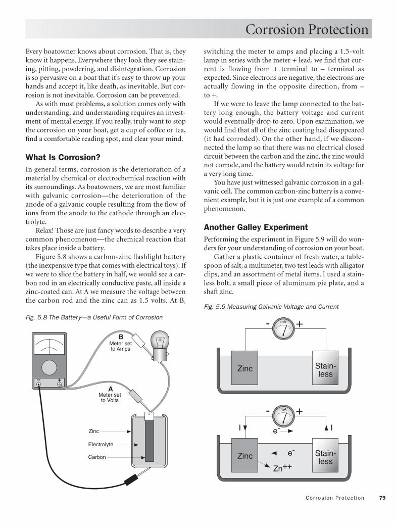
79Cor rosion Protect ion
Every boatowner knows about corrosion. That is, theyknow it happens. Everywhere they look they see stain-ing, pitting, powdering, and disintegration. Corrosionis so pervasive on a boat that it’s easy to throw up yourhands and accept it, like death, as inevitable. But cor-rosion is not inevitable. Corrosion can be prevented.
As with most problems, a solution comes only withunderstanding, and understanding requires an invest-ment of mental energy. If you really, truly want to stopthe corrosion on your boat, get a cup of coffee or tea,find a comfortable reading spot, and clear your mind.
What Is Corrosion? In general terms, corrosion is the deterioration of amaterial by chemical or electrochemical reaction withits surroundings. As boatowners, we are most familiarwith galvanic corrosion—the deterioration of theanode of a galvanic couple resulting from the flow ofions from the anode to the cathode through an elec-trolyte.
Relax! Those are just fancy words to describe a verycommon phenomenon—the chemical reaction thattakes place inside a battery.
Figure 5.8 shows a carbon-zinc flashlight battery(the inexpensive type that comes with electrical toys). Ifwe were to slice the battery in half, we would see a car-bon rod in an electrically conductive paste, all inside azinc-coated can. At A we measure the voltage betweenthe carbon rod and the zinc can as 1.5 volts. At B,
switching the meter to amps and placing a 1.5-voltlamp in series with the meter + lead, we find that cur-rent is flowing from + terminal to – terminal asexpected. Since electrons are negative, the electrons areactually flowing in the opposite direction, from – to +.
If we were to leave the lamp connected to the bat-tery long enough, the battery voltage and currentwould eventually drop to zero. Upon examination, wewould find that all of the zinc coating had disappeared(it had corroded). On the other hand, if we discon-nected the lamp so that there was no electrical closedcircuit between the carbon and the zinc, the zinc wouldnot corrode, and the battery would retain its voltage fora very long time.
You have just witnessed galvanic corrosion in a gal-vanic cell. The common carbon-zinc battery is a conve-nient example, but it is just one example of a commonphenomenon.
Another Galley Experiment Performing the experiment in Figure 5.9 will do won-ders for your understanding of corrosion on your boat.
Gather a plastic container of fresh water, a table-spoon of salt, a multimeter, two test leads with alligatorclips, and an assortment of metal items. I used a stain-less bolt, a small piece of aluminum pie plate, and ashaft zinc.
Corrosion Protection
– +
Carbon
Zinc
Electrolyte
A
B
+
Meter setto Amps
Meter setto Volts
Fig. 5.8 The Battery—a Useful Form of Corrosion
Zinc Stain-less
+-
Zn++
II
e-
e-
Zinc Stain-less
+- mV
mA
Fig. 5.9 Measuring Galvanic Voltage and Current

80 Bonding
Switch the multimeter to volts. Using the test leads,connect the negative (–) lead to the zinc and the posi-tive (+) lead to the stainless bolt and lower both piecesinto the water. Surprised? The meter will indicate avoltage.
Now switch the meter to milliamps. You may ormay not read any current, but hold on. Dump thetablespoon of salt into the fresh water and stir. Depend-ing on the sizes of the electrodes, you will now proba-bly measure a current of about a milliamp flowingfrom the stainless bolt to the zinc.
What’s going on? When two dissimilar metals areplaced together in an electrolyte (electrically conduc-tive medium), one of the metals will assume a higherpotential than the other. In Chapter 1 we learned thatcurrent flows only in a closed circuit. Two electrodes,immersed in electrolyte, form an open circuit, and nocurrent flows. But when we connect the two electrodes,either with a wire or by letting them touch, we com-plete the circuit and current flows.
In this case, the current flowing through the meteris from the stainless steel electrode into the zinc elec-trode. (Since electrons carry negative charge, the elec-tron flow is actually in the opposite direction, but nevermind.)
Figure 5.10 shows what is happening to the zinc onan atomic level. Zinc atoms are changing into positivelycharged zinc ions by giving up two electrons. Thesereleased electrons are flowing from the zinc to thestainless through the meter leads, and the newlyformed zinc ions are departing the zinc electrode andmigrating into the electrolyte—the zinc is corroding.
Continue the experiment if you wish by substitut-ing other pairs of dissimilar metals. As long as the elec-trode metals are different in composition, they willalways generate a potential difference, and current willalways flow into the lower-voltage metal. The voltagedifference will be the same, whether the water is salt orfresh. The currents, however, will be much greater insalt water due to its greater conductivity.
The potential difference between any two dissimilarmetals can be predicted by consulting a table of gal-vanic potentials. The table lists the potential differencesmeasured between the metal in question and a refer-ence electrode, typically silver-silver chloride. Table 5.1reproduces the values listed in Table I of ABYC Stan-dard E-2 for metals and alloys in seawater flowing at 8to 13 feet per second (4.7 to 7.7 knots), and at temper-atures of 50°F to 80°F.
Corrosion Protection
The values in the table are between a metal and asilver-silver chloride electrode. Values between any twometals are found as the differences between the tablevalues for the two metals.
Example: What is the corrosion (galvanic) poten-tial between silicon bronze and zinc? From Table 5.1 wefind the corrosion potential of silicon bronze vs. thereference to be –0.26 to –0.29 volt (average –0.28 volt)and zinc vs. the reference to be –0.98 to –1.03 volt(average –1.00 volt). Thus the corrosion potentialbetween silicon bronze and zinc is –0.72 volt.
By now you may be thoroughly alarmed at thethought of all the underwater metallic components onyour boat—stainless bolts, stainless or bronze shaft,brass Cutless bearing shell, and aluminum outboarddrive. And well you should be, with all that potential(no pun intended) for corrosion. But let’s press on.
Before continuing our galley experiment, let’sreview what we have learned. We have found that anytwo dissimilar metals or alloys immersed in water willgenerate a potential difference. We have also found thatif the two metals are isolated (neither physically touch-ing nor electrically connected by wire), no current orcorrosion will occur. Good. But what if they cannot beseparated (a bronze prop on a stainless shaft), or whatif we have bonded them for lightning protection (asteel rudder, several bronze through-hulls, and a cop-per ground strip)? Have we shot ourselves in the foot?
Zn
Zn++e-
e-
Atom
Ion
Fig. 5.10 What Happens When Zinc Corrodes

81Cor rosion Protect ion
Table 5.1 ABYC Standard E-2, Galvanic Series of Metals in Seawater Referenced to Silver-Silver Chloride Half Cell(Seawater flowing at 8 to 13 ft./sec. [4.7 to 7.7 kn.], temperature range 50°F to 80°F—except as noted)
Metals and Alloys (Anodic or Least Noble—Active) Corrosion Potential, Volts
Magnesium and Magnesium Alloys –1.60 to –1.63Zinc –0.98 to –1.03 Aluminum Alloys –0.76 to –1.00 Cadmium –0.70 to –0.73 Mild Steel –0.60 to –0.71 Wrought Iron –0.60 to –0.71 Cast Iron –0.60 to –0.71 13% Chromium Stainless Steel, Type 410 (active in still water) –0.46 to –0.58 18-8 Stainless Steel, Type 304 (active in still water) –0.46 to –0.58 Ni-Resist –0.46 to –0.58 18-8, 3% Mo Stainless Steel, Type 316 (active in still water) –0.43 to –0.54Inconel (78% Ni–13.5% Cr–6% Fe) (active in still water) –0.35 to –0.46 Aluminum Bronze (92% Cu–8% AI) –0.31 to –0.42 Nibral (81.2% Cu–4% Fe–4.5% Ni–9% Al–1.3% Mn) –0.31 to –0.42Naval Brass (60% Cu–39% Zn) –0.30 to –0.40Yellow Brass (65% Cu–35% Zn) –0.30 to –0.40 Red Brass (85% Cu–15% Zn) –0.30 to –0.40 Muntz Metal (60% Cu–40% Zn) –0.30 to –0.40 Tin –0.31 to –0.33 Copper –0.30 to –0.5750-50 Lead–Tin Solder –0.28 to –0.37 Admiralty Brass (71% Cu–28% Zn–1% Sn) –0.28 to –0.36Aluminum Brass (76% Cu–22% Zn–2% AI) –0.28 to –0.36Manganese Bronze (58.5% Cu–39% Zn–1% Sn–1% Fe–0.3% Mn) –0.27 to –0.34 Silicon Bronze (96% Cu max–0.8% Fe–1.5% Zn–2% Si–0.75% Mn–1.6% Sn) –0.26 to –0.29 Bronze-Composition G (88% Cu–2% Zn–10% Sn) –0.24 to –0.31Bronze ASTM B62 (thru-hull) (85% Cu–5% Pb–5% Sn–5% Zn) –0.24 to –0.31Bronze-Composition M (88% Cu–3% Zn–6.5% Zn–1.5% Pb) –0.24 to –0.3113% Chromium Stainless Steel, Type 410 (passive) –0.26 to –0.35Copper Nickel (90% Cu–10% Ni) –0.21 to –0.28Copper Nickel (75% Cu–20% Ni–5% Zn) –0.19 to –0.25 Lead –0.19 to –0.25Copper Nickel (70% Cu–30% Ni) –0.18 to –0.23 Inconel (78% Ni–13.5% Cr–6% Fe) (passive) –0.14 to –0.17Nickel 200 –0.10 to –0.2018-8 Stainless Steel, Type 304 (passive) –0.05 to –0.10Monel 400, K-500 (70% Ni–30% Cu) –0.04 to –0.14 Stainless Steel Propeller Shaft (ASTM 630:#17 and ASTM 564:#19) –0.03 to +0.1318-8, 3% Mo Stainless Steel, Type 316 (passive) 0.00 to –0.10Titanium –0.05 to +0.06 Hastelloy C –0.03 to +0.08 Stainless Steel Shafting (Bar) (UNS 20910) –0.25 to +0.06Platinum +0.19 to +0.25Graphite +0.20 to +0.30
(Cathodic or Most Noble—Passive)

82 Bonding
To find out if we are in trouble, let’s continue ourgalley corrosion experiment. First repeat the zinc vs.stainless test in Figure 5.10. Next add a piece of alu-minum as a third electrode. Using alligator clip leads,connect the zinc, stainless, and aluminum electrodes, asshown in Figure 5.11. Now set the multimeter to mil-liamps and insert it, one at a time, in each of the leadsto detect current flow.
Amazing! Electric current is flowing out of thestainless electrode and into the zinc electrode, but nocurrent at all is flowing either into or out of the alu-minum electrode. Since metal is lost only by an elec-trode that receives current, it seems that the zinc is pro-tecting the aluminum by sacrificing itself.
You can repeat this experiment with any three met-als you wish, and the results will always be the same:when dissimilar metals in an electrolyte are mechani-cally or electrically bonded, the only metal to corrodewill be the one highest in the galvanic series. The metalmost used in boats for this purpose is zinc.
The phenomenon just observed is called cathodicprotection, and the zinc masses are called zinc anodesor just zincs.
Figure 5.12 shows two examples of cathodic protec-tion using zincs. At top is an outboard engine mountedon the transom of a boat. A large zinc is bolted directlyto the transom underwater, and a wire is run from themounting bolts of the zinc to the outboard. The zincprotects the outboard. The zinc could also have been—and often is—bolted directly to the underwater shaft ofthe outboard.
At the bottom of Figure 5.12 is a sailboat with a zincon the propeller shaft. The zinc is mechanically (andthus electrically) connected to the shaft. Protection isextended to the rudder shaft by a conductor from rud-der to engine block. Rudder, rudder shaft, engine,transmission, prop shaft, and prop are all connectedand thus protected by the zinc. The presence of a non-conductive plastic or rubber shaft coupling wouldrequire a jumper strap across the coupling. It should benoted that the ABYC also permits shafts and ruddersto be protected separately, each by its own zinc anode.
Figure 5.13 shows a variety of zincs commonlyfound in chandleries. Many more shapes and formsare available from specialty suppliers. Engine zincs aremounted inside the cooling systems of engines. Theguppy is used at anchor or in a marina slip and will bediscussed below.
Corrosion Protection
Zinc Alum Stain-less
I I
Zn++
e- e-I=0
mA mA mA
Fig. 5.11 How a Sacrificial Zinc Anode Works
StainlessBronzeZinc collar
Bond
AluminumZinc
Bond
Fig. 5.12 Two Examples of Zinc-Anode Protection
SHAFT ZINCS ENGINE ZINCS
KEEL ANDRUDDER ZINCS
TRANSOM ZINC “GUPPY” ZINC
Fig. 5.13 An Assortment of Zincs

83Stray -Cur rent Protect ion
Even if you’re flushed with your recent mastery ofthe subject of galvanic corrosion, I suggest you take abreak at this point because we have to start all overagain. It turns out there is more than one way to createa potential difference between underwater metals. Wehave another dragon to slay—stray-current corrosion.
Galley Experiment, Continued OK, back to work. As a refresher, place two identicalaluminum electrodes in the saltwater solution, as inFigure 5.14. Using the multimeter, measure the voltagebetween the electrodes. Then switch the multimeter tomilliamps and measure the current in the wire betweenthe electrodes. The result should be the same in bothcases: zero.
Next place a 1.5-volt battery between the same twoaluminum electrodes, A and B, as in Figure 5.15. Now,of course, you will measure the battery’s 1.5 volts acrossthe electrodes and, with the meter placed in series withthe battery, a current flowing from the battery positive(+) terminal into electrode B. If you let the experimentgo on long enough, you will observe that the electrodeinto which the current flows is corroding, just as it didwith galvanic corrosion. It is apparent that it makes nodifference whether the potential difference between theelectrodes is due to their being of dissimilar metals ordue to a voltage impressed on them from an outsidesource—the electrode receiving current always cor-rodes. When the impressed voltage is accidental (asfrom a poorly insulated electrical connection), the cor-rosion is termed stray-current corrosion. Since stray, oraccidental, voltage sources can be much greater thangalvanic potentials (up to 12 volts, compared to a fewtenths of a volt), stray current corrosion can be muchmore damaging than galvanic corrosion.
Finally, we’ll use four aluminum electrodes asshown in Figure 5.16. As in the previous test, Figure5.15, we’ll use electrodes A and B to force a current inthe seawater. Now insert the connected pair, C and D,between A and B. Measure the current between C andD. It will be approximately the same as in the previousexperiment. Likewise, electrode C will eventually showsigns of corrosion.
Now you see why this insidious phenomenon istermed stray-current corrosion. Two perfectly innocentmetal objects, if electrically bonded, can pick up straycurrent flowing through the electrolyte and partici-pate in the corrosion process!
Stray-Current Protection
0 VoltsI=0 I=0
+- mA
+- mV
A B
Al Al
Fig. 5.14 Experiment Setup
II
A B
1.5V+-
Fig. 5.15 Impressing (Forcing) Current with a VoltageSource
Fig. 5.16 Stray Current Impressed by Voltage Field

84 Bonding
Figure 5.17 shows a boat floating in an externalvoltage and current field (perhaps due to an adjacentboat). The voltage difference, from left to right acrossthe illustration, is 1.0 volt.
Since the electrical resistance of the path fromground plate to bonding wire to engine to shaft to pro-peller is less than that of the water path, electric current
Stray-Current Protection
flows into the ground plate, through the bonding sys-tem and out of the propeller. And since the current isflowing into the propeller from the bonding system, thepropeller will corrode.
Figure 5.18 shows that a sacrificial zinc on the shaftwill divert the current flow to itself and save the prop.
Radio
Groundplate
No zinc—propcorrodes
Bondingwire
1V0V 0.5V
I
0.5V
Radio
Groundplate
Bondingwire
1V0V 0.5V
I
0.5V
Zinc—propprotected
Fig. 5.17 Stray-Current Corrosion Caused by an External Voltage Field
Fig. 5.18 Cathodic Protection from Stray-Current Corrosion Caused by an External Voltage Field
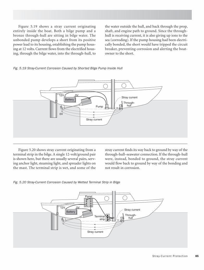
85Stray -Cur rent Protect ion
Figure 5.19 shows a stray current originatingentirely inside the boat. Both a bilge pump and abronze through-hull are sitting in bilge water. Theunbonded pump develops a short from its positivepower lead to its housing, establishing the pump hous-ing at 12 volts. Current flows from the electrified hous-ing, through the bilge water, into the through-hull, to
the water outside the hull, and back through the prop,shaft, and engine path to ground. Since the through-hull is receiving current, it is also giving up ions to thesea (corroding). If the pump housing had been electri-cally bonded, the short would have tripped the circuitbreaker, preventing corrosion and alerting the boat-owner to the short.
Stray current
Battery
12V 0V
0V
PumpThrough-
hull
Stray current
Stray current
12V 0V
Through-hull
Panel
Terminalstrip
BatteryStray current
Fig. 5.19 Stray-Current Corrosion Caused by Shorted Bilge Pump Inside Hull
Fig. 5.20 Stray-Current Corrosion Caused by Wetted Terminal Strip in Bilge
Figure 5.20 shows stray current originating from aterminal strip in the bilge. A single 12-volt/ground pairis shown here, but there are usually several pairs, serv-ing anchor light, steaming light, and spreader lights onthe mast. The terminal strip is wet, and some of the
stray current finds its way back to ground by way of thethrough-hull–seawater connection. If the through-hullwere, instead, bonded to ground, the stray currentwould flow back to ground by way of the bonding andnot result in corrosion.

86 Bonding
We have just seen three cases of stray-current corro-sion. Two would have been prevented by bonding, butone was, in fact, caused by bonding. In general, bondingof immersed metal components prevents corrosion dueto stray currents from inside the hull, but it causes cor-rosion due to stray currents from outside the hull.
Two opposite solutions to this dilemma are to: (1)bond everything and protect, and (2) unbond every-thing and isolate.
To Bond or Not to Bond
Bond and Protect Figure 5.21 shows the bond-and-protect principle.Every underwater mass is connected to the boat’sbonding system. To protect against stray currents out-side of the hull, sacrificial anodes are connected to thebonding system and placed where they may best pro-tect all underwater masses.
12V 0V
Through-hull
Radio
Groundplate
Bonding
Zinc
Commonground
Battery
12V 0V
Through-hull
Radio
Groundplate
Bonding
Unbonded
Zinc Isolatingflexiblecoupling Isolated
Battery
Fig. 5.22 The Unbond-and-Isolate Approach
Fig. 5.21 The Bond-and-Protect Approach
Unbond and Isolate Figure 5.22 shows the alternative unbond-and-isolateprinciple. Underwater masses are isolated so neithergalvanic nor outside stray current can flow betweenthem. The only bonded underwater mass is the light-ning and radio ground. Masses entirely within the hull(engine, transmission, metal tanks, and mast) arebonded to the boat’s bonding system. The shaft is iso-lated by an insulating flexible coupling. The prop isprotected by a shaft zinc if prop and shaft are of dissim-ilar metals.
The Pros and Cons of Bonding Bonding and protecting offers the advantage of greaterwetted surface area for the lightning and radiogrounds.
On the other hand, proponents of the unbond-and-isolate approach claim that the lightning ground stripor plate provides adequate ground for both lightningand SSB radio, and that electrochemical reactions atbonded wooden hull through-hulls dangerously softenthe surrounding wood. The ABYC favors the bond-and-protect approach, but specifically states that elec-trically isolated through-hull fittings need not bebonded.

87Siz ing the Anode(s)
The ABYC recommends a method (in Standard E-2,Appendix 3) using a silver-silver chloride referenceelectrode for determining the amount of cathodic pro-tection (size of aggregate zinc anodes) required to pro-tect the underwater metals of a boat. The methodassumes the use of zincs meeting Military SpecificationMIL-A-18001 (99.2% zinc minimum), excellent(metal-to-metal) electrical contact between anode andmetal to be protected, and no paint on the anode.
The standard further points out that cathodic pro-tection requirements increase with boat speed, salinity(if salt water), acidity (if fresh water), frequency of useof the boat, and deterioration over time of the anode.
ABYC Method 1. Assemble your materials:
• silver-silver chloride reference electrode withlead (widely available on the Web or at WestMarine stores for about $80)
• digital multimeter (DMM) having at least 10MW input impedance (even inexpensiveDMMs do)
• several high-quality zinc anodes of appropri-ate type (shaft collar, prop, or hull zincs)
• two 20-foot test leads with strong clips2. Starting with the hull free of all zinc anodes,
lower the silver-silver chloride electrode into thewater near the metal to be protected.
3. Set the DMM to the 2 Volts DC setting.4. Connect the lead from the reference electrode
to the DMM – input.5. Using a test lead, connect the metal to be pro-
tected to the DMM + input. Make sure the testlead clip makes a clean electrical connection tothe metal.
6. Note the DMM reading (example: –0. 720 volt).7. Using the second test lead, connect one of the
zinc anodes to the metal to be protected andlower the zinc into the water.
8. Note the new DMM reading. The zinc is ade-quate if it has lowered the voltage by at least0.200 volt (example: from –0.720 volt to –0.920volt or less).
9. If the second reading isn’t at least 0.200 voltmore negative than the first, the zinc is not suf-ficient. Increase either the zinc area or the num-ber of zincs and retest.
Sizing the Anode(s)
DCV ACV mAΩ
+–
DMM on DC volts
No zinc
DCV ACV mAΩ
Referenceelectrode
STEPS 1–6
STEPS 7–9
+–
Referenceelectrode
Proposed zinc
Fig. 5.23 ABYC Method for Sizing Cathodic Protection

88 Bonding
Test 1: Stray Currents In a bonded system, stray current will be captured bythe boat’s bonding conductor. Stray current in athrough-hull or other accessible underwater mass canbe measured with a digital multimeter on the mil-liamps (mA) setting as shown in Figure 5.24.
Disconnect the bonding conductor and place themeter between the end of the conductor and the metalof the through-hull. Current into or out of the through-hull will now flow through the meter. Repeat the testwith each fitting, as well as the rudder shaft, prop shaft,and strut or shaft log. Remember that current flowingfrom the bonding conductor into the fitting, as shown,is causing corrosion of the fitting. Current of as little as1 milliamp is reason for concern as it will, over the 8,766hours in a year, cause serious damage to the fitting.
Test 2: Corrosion Potentials This test (Figure 5.25), using a digital multimeter anda silver-silver chloride reference electrode, will deter-mine whether the boat’s present sacrificial zincs areprotecting the boat’s underwater metallic masses:
1. Set the multimeter to measure DC volts.2. Connect the meter’s + input to an underwater
metallic mass or, if there is a common bondingsystem (as shown), to engine negative ground.
3. Connect the reference electrode to the meter’s –input, and lower the electrode into the water.
Compare the reading to those of Table 5.2 to seewhether the zinc anodes are adequate. If the readingsindicate underprotection, replace or add zinc anodes.
Testing Your Protection
Table 5.2 Interpreting Corrosion Test Voltages
Underwater Under- Over-Metal protected Protected protected
Bronze < 0.44 V 0.44–0.70 V > 0.70 VSteel < 0.75 V 0.75–0.95 V > 0.95 V
Aluminum < 0.90 V 0.90–1.10 V > 1.10 V
Readings in excess of 1.10 volts usually indicate avoltage field in the water surrounding the boat. If youcan’t eliminate or reduce the external field, considerunbonding and isolating the underwater fittings, asshown in Figure 5.22.
12V 0V
Through-hull
Radio
Groundplate
Bonding
Zinc
Commonground
Battery
Silver-silver chloride
electrode
DCV ACV mAΩ
+ –
Digital multimeteron DC volts
DCV ACV mAΩ
+ –
Digital meteron milliampssetting
Bondingconductor
Fig. 5.24 Test for Stray Current
Fig. 5.25 How to Evaluate Your Boat’s Corrosion Potential

89Noncathodic Cor rosion
We have addressed the types of corrosion that can beeliminated by cathodic protection. There are furtherannoying types of corrosion on a boat that must beaddressed by other means.
DezincificationFigure 5.26 shows the dezincification of brass screws.Brass consists of a mixture of copper and zinc. Com-mon yellow brass contains 65% copper and 35% zinc.In the presence of moisture (a very common electrolytearound boats!), the zinc and copper react galvanically,just as they would underwater, although more slowly.The result is a loss of zinc and loss of strength. When abadly dezincified screw is removed, the screw headoften snaps off. The lesson: use only stainless or bronzescrews around a boat.
A second instance of dezincification occurs inbronze (an alloy of copper, tin, and zinc) propellers.Loss of zinc is evidenced by a telltale change of themetal from bright yellow to a pinkish hue.
Stainless Screws in Aluminum Figure 5.27 shows what happens when a fitting of anymaterial, metallic or nonmetallic, is attached to an alu-minum mast or boom with stainless screws. Regard-less of how well machined the threads are, there arealways microscopic spaces between the screw and thebody. If salt water finds its way into these capillaryspaces, an ideal galvanic cell is set up with resulting lossof aluminum in the area of the threads. Ultimately, thestainless screw seizes in the hole or, worse, falls outunder load. Filling both sets of threads with siliconesealant or grease before fastening will fill the capillaryspaces around the threads and prevent the intrusionof salt water. No seawater—no electrolyte—no corro-sion.
Noncathodic Corrosion
Dezincification(loss of zincand strength)
Capillary moistureresults in corrosion
Stainless screw
Silicone sealantor grease in threads(exaggerated)
Fitting
Aluminum mast
Stainless screw
Fig. 5.26 Dezincification of Brass
Fig. 5.27 Seizing of Stainless Screws in Aluminum

90 Bonding
Stainless Pitting Figure 5.28 shows how stainless (pronounce “stain-less”) steel develops corrosion pits. Stainless steel isprincipally an alloy of iron and chromium. Whenexposed to the oxygen in air, the chromium oxidizesand forms a shiny protective skin (the stainless is thensaid to be passivated). The chromium oxide skin is verynoble in the galvanic series (see Table 5.1, entry 18-8,3% Mo Stainless Steel, Type 316 [passive]), so it resistscorrosion and protects the iron beneath.
If the surface is immersed in or covered with anoxygen-free liquid, however, the chromium loses itsoxygen, the passive skin is lost, and the iron is free torust. In Figure 5.27 a barnacle has attached itself to astainless surface, depriving the chromium-oxide skin ofoxygen. The unpassivated area and the surroundingpassivated area then act as a galvanic couple, resultingin corrosion of the iron under the barnacle.
The same sort of corrosion occurs between stainlessstanchions and their water-retaining bases, explainingthe mysterious rust stains often seen in these areas.
Cavitation Erosion Finally, Figure 5.29 shows cavitation erosion of thetrailing edge of a propeller. Cavitation is the rapid for-mation and collapse of vapor bubbles just behind pro-peller blades. Cavitation is not galvanic corrosion.Instead, the propeller is turning so quickly that thewater immediately behind the blade is left behind,forming water vapor (gaseous form of water) bubbles.As these bubbles subsequently collapse, the water hitsthe blade like thousands of tiny hammers. You can hearthe sharp popping sound underwater when a boatpasses. The result is mechanical destruction and ero-sion of the metal at the trailing edge of the blade. Thesolution is to increase the area of the blade, therebyreducing the pressure difference across the blade.
In contrast, a bronze propeller or any other bronzefitting suffering from galvanic corrosion displays arosy-pink color instead of its normal brassy-yellowcolor. Galvanic corrosion selectively removes the zincfrom the bronze, leaving the reddish copper behind.
Noncathodic Corrosion
Barnacle or dirt
Stainless steel passivatedby layer of chromium oxide
Stainless steel activatedby lack of oxygen
AnodeCathode
Deep pit leads tocontinued corrosion
Cavitationerosion
Cavitationerosion
Fig. 5.28 Pitting of Stainless Steel
Fig. 5.29 Erosion Due to Cavitation

91The ABYC on Cathodic Protect ion
The following general recommendations are takenfrom ABYC Standard E-2, Cathodic Protection of Boats,Section E-2.4.
a. Although cathodic protection will, depending on the cur-rent capability of the system, help to minimize stray-current corrosion when it exists, stray-current corrosionshould be controlled by:
(1) Minimizing DC and AC electrical leakage levels fromelectrical products, and
(2) The use of a bonding system in accordance withABYC E-1, “Bonding of Direct Current Systems.”
b. Factors that affect the type and degree of cathodic pro-tection required:
(1) Water Velocity—Cathodic protection current re-quirements increase with water velocity past the hull.The current requirements can be as high as 30 timesthat required in still water.
(2) Boat Usage—More frequently operated vesselsrequire more cathodic protection than vessels infre-quently used.
(3) Fresh and Sea Water—Current requirements increasewith salinity but higher driving potentials arerequired in fresh water.
(4) Deterioration of Protective Coatings—Current re-quirements increase as protective coatings deterio-rate.
c. The need for a cathodic protection system for metalappendages on nonmetallic hulls may not be justified if themetals coupled are galvanically compatible.
d. Hull-mounted metallic trim tabs may be electrically iso-lated from the boat’s bonding system to reduce the load onthe boat’s cathodic protection system, providing the trimtabs are also electrically isolated from their electrical actuat-ing mechanism. If the trim-tab system is connected to theboat’s bonding system the cathodic protection system’s mil-liampere rating will have to be increased to provide the addi-tional protection.
e. A cathodic protection system shall be capable of inducingand maintaining a minimum negative shift of 200 millivoltsin the potential of the composite cathode being protected.
f. Since the area relationship of metals in a galvanic cell willaffect current density and therefore corrosion rate, theimmersed cathodic metal surfaces may be coated to obtaina more favorable anode to cathode area relationship. Coat-ings shall not contain pigments that will form galvanic cou-ples with the substrate. Coatings on substrate and coatingson surfaces must be able to tolerate alkali generated by thecathodic reaction.
g. Impressed-current anodes shall have the words “DO NOTPAlNT” on a visible surface when installed.
NOTE: Anodes are ineffective if painted.
h. In general, the use of several anodes instead of one largeanode will tend to provide better distribution of the protec-tive current. Sacrificial anodes may be mounted remotely;the best current distribution will be obtained with theanode(s) positioned to be as equidistant as possible fromthe metals to be protected.
i. Anodes should be faired and, if possible, arranged in a lon-gitudinal row to minimize drag. After installation, peripheralcrevices should be sealed.
j. Anodes shall be mounted on a sloping surface that cannotentrap gas bubbles.
k. If anodes are located near through-hull fittings they shallbe positioned forward of discharge fittings and aft of intakeports. Anode locations that disturb the flow of water past thepropeller should be avoided.
l. All metals which are to receive cathodic protection fromthe cathodic protection system must have good electricalcontinuity to the boat bonding system. Galvanic anodes, ifused, must be affixed in a manner that electrical continuity ismaintained with the metals they are to protect, eitherthrough their mounting means or through the boat’s bond-ing system.
(1) Propeller shafts do not provide reliable electrical con-tinuity to the boat’s bonding system.
(2) Rudder posts shall be cathodically bonded by meansof a flexible conductor positioned to allow full ruddermovement without stressing the cathodic bondingconductor or its connection.
m. In general, sacrificial anodes may be mounted directlyon the metal to be protected, but the best current distribu-tion will be obtained by remote mounting with the anode(s)positioned to be as equidistant as possible from the metals tobe protected.
n. The negative potential (–1,050 millivolts as compared tosilver-silver chloride reference electrode) that can beachieved by some corrosion control systems will result insome decrease in the effectiveness of antifouling paints.Because the decrease in the effectiveness increases withhigher negative voltages, the negative potential should bekept as close to the optimum value as possible. A referencepotential reading in excess of –1,100 millivolts indicatesexcessive cathodic protection.
o. Anodes and reference electrodes shall be positioned toavoid contact with lifting slings and chocks when the boat ishauled.
p. The electrical interconnection that occurs via shore-powercables or metal mooring cables between two vessels orbetween a vessel and submerged metal or the dock mayresult in galvanic corrosion of steel or aluminum hulls andaluminum underwater appendages. An isolator or an isola-tion transformer can break this couple.
The ABYC on Cathodic Protection

DC Standards and Practices
92
CHAPTER 6
Starter
Solenoid
Battery
–
Battery
–Cranking-motorconductor (nolength restriction)
72" max.
72" max.
7" max.or40" max. No limit
Fuseor
breaker
DUAL BATTERIES
+
+
Copyright © 1993, 2006 by Charlie Wing. Click here for terms of use.

93
Standards and recommended practices for thewiring of boats are promoted by the AmericanBoat and Yacht Council (ABYC). This chapter
delineates and explains these standards. Preliminary tothe standards, however, we first explain the wisdom ofcreating wiring diagrams for your boat’s electrical sys-tems.
The standards and practices start with the specifica-tion of acceptable marine wire. The ABYC DC load cal-culation method allows you to calculate the maximumcurrent expected to flow in a conductor and to use thetables for allowable amperage of conductors and con-ductor sizes for allowable voltage drops.
Wiring and, later, troubleshooting are both facili-tated by the proper identification of conductors, as wellas the proper installation of wire runs.
As in a home, overcurrent protection, in the form offuses and circuit breakers, guards against overheatingand possible fire.
The marine environment, characterized by mois-ture, salt, and vibration, makes conductor connectionscritical.
The lethal mixture of gasoline vapors and openflame or electric spark dictates the ABYC-adoptedCoast Guard requirements for ignition protection.

94 DC Standards and Pract ices
When you first bought your boat, you probably judgedits wiring on appearances. Either it looked good or itdid not. You never gave it another thought—untilsomething went wrong. Then you discovered whetheror not the boat had a wiring diagram. Chances are, ifyour boat was American made, it did not.
The person who wired your boat didn’t need awiring diagram. First, yours was probably one ofdozens, if not hundreds, he had wired just like it. Sec-ond, he assumed he would not be there when some-thing went wrong. Troubleshooting would be yourproblem.
One summer I worked in a boatyard rigging andstepping masts. One of my jobs was to check the mastwiring before the mast was stepped. Some masts hadcombined tricolor, anchor, and strobe light (four con-ductors), masthead or steaming light (two conductors),spreader lights (two conductors), windvane light (twoconductors), plus a windspeed indicator (six wires in acable) and a VHF coaxial cable—a total of ten individ-ual conductors plus two cables.
It seemed as if every second mast had a problem. Abulb was burned out or not properly seated, connectorswere corroded, or a wire was broken. The symptomswere obvious—a light at the top of the mast did notcome on. Finding the cause, however, was an art. With-out a wiring diagram, labeled terminals, and color-coded conductors, finding the fault sometimesrequired an hour of labor for two workers: one at thetop end reading voltage or watching the light, the otherat the bottom applying voltage to successive pairs ofconductors. Did you know that the number of possi-ble pairs of n wires is n(n – 1)/2? For 10 wires we hadto check 45 pair combinations!
Sometimes we found that a light that had workedon the ground no longer worked with the mast up.Now there were even more possibilities! Somethingcould have happened inside the mast during stepping,or the problem could lie between the distribution paneland the base of the mast. It was here that we sometimesencountered the case of the chameleon conductor. Awire would leave the distribution panel with blue insu-lation, disappear into the bilge or behind a liner, andemerge at the base of the mast with yellow insulation!
One of my associates had worked for one of the bestboatbuilders in the United States. Over lunch I relatedthe case of the chameleon wire.
“Oh, sure,” he said, “we used to run a wire until thespool ran out. Then we’d grab another spool of what-ever color and splice it in.”
Wiring Diagrams
A proper wiring diagram shows every electricaldevice: circuit breaker, fuse, switch, terminal, and con-ductor, as well as wire size, color, and label. It makestroubleshooting a snap. If a light doesn’t come on, thediagram shows exactly where to check for voltage, allthe way from the lamp back to the distribution panel. Acircuit diagram also shows the best place to tie in addi-tional electrical equipment, what spares to carry, andwhether or not you are fused correctly.
Best of all, if you create your circuit diagram byvisually inspecting your existing wiring, you will havelooked systematically at every component and may beable to spot potential problems before they becomeproblems underway.
Creating a Wiring Diagram Circuit symbols are, like international road signs,intended to convey meaning at a glance. Unlike inter-national signage, however, there is no rigorous stan-dard for wiring symbols. Figure 6.1 shows commonlyused symbols for most of the simple devices encoun-tered in a boat. If these don’t work for you, feel free toinvent your own. For example, you may elect to showa fan as a fan blade and a fuse as a simple rectangle.
If you possess the repair manual for your engine (aminimal and wise investment), it probably contains awiring diagram for the starting motor, alternator, andinstrument panel. If so, you are in luck; you are alreadyhalfway there. Consider the engine diagram to be thefirst of your circuit diagrams and adopt its style for therest of your diagrams.
Breaking the total system into a set of circuits hasthe added advantages of smaller sheets of paper, lessconfusion, and the ability to make changes withoutredrawing the entire system.
A complete set of circuit diagrams for a typicalpleasure boat might include:
• Engine wiring • Engine-starting circuit • Cabin lights and accessories • Navigation lights • Instrumentation and radios • 110 VAC system • Main distribution panel • Mast wiring • Water pumps Don’t worry if several of your diagrams overlap.
The intent is to locate the general area of a fault andthen to isolate the exact location within that area.

95Wir ing Diagrams
A Starter-Motor Circuit
Figure 6.2 shows a very simple diagram of an enginestarter-motor circuit. If one day you turn on the igni-tion switch, push the start button, and nothing hap-pens, this is the circuit diagram you will need. A com-plete engine wiring diagram would probably containthe same information, but it would also contain all ofthe meters, idiot lights, and alternator wiring, addingconsiderable visual confusion.
For the starter-motor circuit all you need to see arethe:
• Battery switch • Fuse between battery switch common terminal
and engine panel • On/Off switch • Momentary start switch • Wire from starting switch to solenoid • Heavy positive cable from battery-select common
terminal to solenoid • Heavy negative cable from battery negative termi-
nal to engine negative terminal.If the engine won’t turn over, the problem proba-
bly lies somewhere in this diagram. For guidance, seepage 64.
+
–
+
–
Battery,single cellor voltage
source
Battery,multi-cell
Conductors,no connection
Conductors,connected
Resistor
Lightbulb(lamp)
Switch (SPST)single-polesingle-throw
Switch (SPDT)single-pole
double-throw
Switch (DPST)double-polesingle-throw
Switch (PBNO) push-button
normally open
Earthground
Equipmentground
Fuse
Circuitbreaker
V Voltmeter
F Fan
Dioderectifier
M MotorVariableresistor
Capacitor
Variablecapacitor
A Ammeter
+12V
–
+12V
–
ON–OFFKey switch
STARTPush button
Engine panel
Starter
Solenoid
1 2
Engineground
Batteryswitch
Fuse onengine (30A)
Fig. 6.1 Wiring Symbols
Fig. 6.2 Typical Starter-Motor Circuit

96 DC Standards and Pract ices
A Cabin Lighting Circuit
Although it shows 15 separate lights and fans, the cabinlighting diagram in Figure 6.3 is even simpler in con-cept than the engine starter circuit. The diagram con-sists of two similar, but separate, branch circuits.
On the right is the starboard cabin lighting circuit,originating at a 10-amp circuit breaker in the DC dis-tribution panel and running forward to serve all of thelights and fans on the starboard side. The positive con-ductor is a red AWG (American Wire Gauge) 14 wirelabeled “27.” The negative conductor is a black AWG14 wire labeled “28.” Except for the two paralleled maincabin lights, each light and fan is controlled by an indi-vidual single-pole, single-throw switch. You may wishto include model numbers and specifications for eachdevice so that you can calculate current draws and findreplacement parts.
The devices are drawn on paper as laid out in theboat so that we can physically pinpoint a problem. Forexample, if the chart table light failed, but the main aftlight still worked, the circuit diagram would allow us toimmediately isolate the problem to either the charttable light or the lamp’s controlling switch.
On the other hand, if the main aft, main forward,and V-berth lights failed as well, we would suspect theproblem to be in either the positive or negative conduc-tors or the connections between the night light and thechart table light.
On the left is the similar port cabin lighting circuit,originating at a 10-amp circuit breaker in the DC dis-tribution panel and running forward to serve all of thelights and fans on the port side. The positive conductoris a red AWG 14 wire labeled “29.” The negative con-ductor is a black AWG 14 wire labeled “30.”
Wiring Diagrams
F
F
V-berthfan
V-berth
Mainforward
Mainaft
Headfluorescent
Galleyfluorescent
Galleyincandescent
Galleyfan
V-berth
Mainforward
Mainaft
Charttable
Nightlight
Quarterberth
Quarterfan
Stbd lights, 10AAWG 14 red #27
Port lights, 10AAWG 14 red #29
AWG 14 black #30
AWG 14 black #28
PORT STARBOARD
F
Fig. 6.3 Typical Cabin Lighting Circuits

Real circuits consist not of pencil lines on a sheet ofpaper, but of real metal conductors having finite elec-trical resistance. The conductors and their installationsshould satisfy a number of criteria:
1. Construction should be such that the conduc-tor will not break under continuous vibrationor an accidentally imposed force.
2. Insulation should be appropriate for theexpected maximum ambient (surrounding air)temperature and degree of exposure to sunlight,moisture, and air.
3. Ampacity (current-carrying capacity) should besufficient to avoid overheating.
4. Conductor size should be selected consideringconductor length and current in order that volt-age drop not impair the functioning of the loaddevices.
Construction The ABYC calls for most conductors to be stranded andof size AWG 16 minimum. An exception is sheathedAWG 18 conductors that do not extend more than 30inches beyond their sheath.
Because copper wire becomes brittle with flexing,solid wire (as used in house wiring) is not allowed atall. Type II stranding is the minimum allowed for gen-eral boat wiring, and Type III stranding should be usedwherever vibration is expected, such as on an engine.
Table 6.1 shows the minimum circular-mil areas (acircular mil is the area of a 0.001-inch-diameter circle)for both AWG and SAE (Society of Automotive Engi-
neers) conductors and the minimum numbers ofstrands specified by the ABYC for AWG 18 throughAWG 4/0 (0000) conductors.
InsulationAll single-conductor and cable insulations should beone of the types listed in Table 6.2, appropriate to itsexpected exposure to temperature, moisture, and oil.The letters in the designations stand for:
T thermoplastic M oil resistant W moisture resistant H heat resistant to 75°C
HH high-heat resistant to 90°C An insulated jacket or sheathing may qualify for
more than one rating and be labeled as such. The mostcommonly available cable suitable to all applications inthe typical boat is probably UL 1426 boat cable.
Table 6.2 Acceptable Insulation Types
Type Description
CONDUCTORSTHW Moisture and Heat Resistant, Thermoplastic TW Moisture Resistant, Thermoplastic
HWN Moisture and Heat Resistant, Thermoplastic XHHW Moisture and High-Heat Resistant, Cross-Linked
Synthetic Polymer MTW Moisture, Heat, and Oil Resistant, Thermoplastic AWM Moisture, Heat, and Oil Resistant, Thermoplastic,
Thermosetting UL 1426 Boat Cable
SAE CONDUCTORS GPT Thermoplastic Insulation, Braidless HDT Thermoplastic Insulation, Braidless SGT Thermoplastic Insulation, BraidlessSTS Thermosetting Synthetic-Rubber Insulation,
BraidlessHTS Thermosetting Synthetic-Rubber Insulation,
BraidlessSXL Thermosetting, Cross-Linked Polyethylene
Insulation, Braidless
FLEXIBLE CORDS SO Hard-Service Cord, Oil Resistant ST Hard-Service Cord, Thermoplastic
STO Hard-Service Cord, Oil Resistant, Thermoplastic SEO Hard-Service Cord, Oil Resistant, ThermoplasticSJO Junior Hard-Service Cord, Oil ResistantSJT Hard-Service Cord, Thermoplastic
SJTO Hard-Service Cord, Oil Resistant, Thermoplastic
Marine Wire
Table 6.1 Minimum Circular-Mil (CM) Areas and Stranding
Conductor Minimum Minimum Minimum StrandsGauge CM for AWG CM for SAE Type II Type III
18 1,620 1,537 16 – 16 2,580 2,336 19 26 14 4,110 3,702 19 41 12 6,530 5,833 19 65 10 10,380 9,343 19 105 8 16,510 14,810 19 168 6 26,240 25,910 37 266 4 41,740 37,360 49 420 2 66,360 62,450 127 665 1 83,690 77,790 127 836 0 105,600 98,980 127 1,064
2/0 133,100 125,100 127 1,323 3/0 167,800 158,600 259 1,666 4/0 211,600 205,500 418 2,107
97Marine Wire

98 DC Standards and Pract ices
AmpacityBranch circuit conductors should be sized to carry themaximum currents drawn by their loads. In the caseof motors, maximum current should be for the locked-rotor, or stalled, condition.
ABYC DC Load Calculation
Main feed conductors for distribution panels andswitchboards should be determined using the ABYCprocedure, shown in Table 6.3 (a sample calculation isshown).
Table 6.3 ABYC Load Calculation Method (for total electrical loads for minimum sizes of panelboards, switchboards, andmain conductors) NOTE: Calculations are based on the actual operating amperage for each load and not on the rating of the circuit breakeror fuse protecting that branch circuit.
Column A
List each of the loads that must be available for use on acontinuous basis.
Equipment Amperes
Navigation lights 5.5
Bilge blower(s) 2.0
Bilge pump(s) 4.2
Wiper(s) 0.0
Largest radio (transmit mode) 2.5
Depth sounder 0.9
Radar 7.5
Searchlight 12.0
Instruments 2.3
Alarm system (standby mode) 0.5
Refrigeration 5.5
Other: Autopilot 3.5
Total of Column A 46.4
Enter Total from Column B 80.0
Sum of Totals (Total Load) 126.4
Column B
List the intermittent loads. The largest load or 10% of thetotal, whichever is greater, will be carried to Column A.
Equipment Amperes
Cigarette lighter 0.0
Cabin lighting 10.0
Horn 6.3
Additional electronics 10.0
Trim tabs 0.0
Power trim 0.0
Heads 0.0
Anchor windlass 80.0
Winches 0.0
Freshwater pumps 5.8
Other: Microwave 60.0
Total of Column B 172.1
10% of Column B 17.2
Largest item in Column B 80.0
Larger of above two lines— 80.0Enter in both Column A and Column B

99Al lowable Conductor Amperage
Having the maximum load current in amps and thetemperature rating of the conductor insulation, theminimum required conductor size is selected fromTable 6.4.
Allowable Conductor Amperage
Table 6.4 Allowable Amperage of Conductors for Under 50 Volts (Adapted from ABYC Standard E-11, Table IV)
Conductor Temperature Rating of Conductor Insulation Size, AWG 60°C (140°F) 75°C (167°F) 80°C (176°F) 90°C (194°F) 105°C (221°F) 125°C (257°F) 200°C (392°F)
Outside Engine Spaces
18 10 10 15 20 20 25 25
16 15 15 20 25 25 30 35
14 20 20 25 30 35 40 45
12 25 25 35 40 45 50 55
10 40 40 50 55 60 70 70
8 55 65 70 70 80 90 100
6 80 95 100 100 120 125 135
4 105 125 130 135 160 170 180
2 140 170 175 180 210 225 240
1 165 195 210 210 245 265 280
1/0 195 230 245 245 285 305 325
2/0 225 265 285 285 330 355 370
3/0 260 310 330 330 385 410 430
4/0 300 360 385 385 445 475 510
Inside Engine Spaces
18 5.8 7.5 11.7 16.4 17.0 22.3 25.0
16 8.7 11.3 15.6 20.5 21.3 26.7 35.0
14 11.6 15.0 19.5 24.6 29.8 35.6 45.0
12 14.5 18.8 27.3 32.8 38.3 44.5 55.0
10 23.2 30.0 39.0 45.1 51.0 62.3 70.0
8 31.9 48.8 54.6 57.4 68.0 80.1 100.0
6 46.4 71.3 78.0 82.0 102.0 111.3 135.0
4 60.9 93.8 101.4 110.7 136.0 151.3 180.0
2 81.2 127.5 136.5 147.6 178.5 200.3 240.0
1 95.7 146.3 163.8 172.2 208.3 235.9 280.0
1/0 113.1 172.5 191.1 200.9 242.3 271.5 325.0
2/0 130.5 198.8 222.3 233.7 280.5 316.0 370.0
3/0 150.8 232.5 257.4 270.6 327.3 364.9 430.0
4/0 174.0 270.0 300.3 315.7 378.3 422.8 510.0

100 DC Standards and Pract ices
All wire has resistance. As current flows through thewire, voltage drops according to Ohm’s Law. If power issupplied to a circuit by a 12.0-volt battery and the volt-age drops 0.5 volt in the positive conductor going to theload and another 0.5 volt in the negative conductorback to the battery, then the voltage across the load isnot 12.0 volts, but 12.0 – 0.5 – 0.5 = 11.0 volts. Thevoltage drop in the total length of conductor to andfrom the load is thus 1.0/12.0 = 8.3%.
The ABYC specifies two allowable percentage drops,depending on the effect on safety:
• 3% for panelboard feeds, bilge blowers, electron-ics, and navigation lights
• 10% for general lighting and other noncriticalapplications
Required conductor size may be determined from:
CM = 10.75 × I × L/E
Allowable Voltage Drop
where: CM = conductor circular mils (Table 6.1) I = current in amps L = round-trip length in feet E = voltage drop in conductor, volts
Example: What size conductor is required for ananchor light drawing 0.9 amp at the top of a 50-foot mastwith a 15-foot run from panelboard to base of the mast?
The light is a navigation light, so the allowed voltagedrop is 3% of 12 volts or 0.36 volt. The length of theconductor from panelboard to the light and back to thepanelboard is 15 feet + 50 feet + 50 feet + 15 feet = 130feet. The minimum circular-mil area of the conductoris thus
CM = 10.75 × 0.9 × 130/0.36 = 3,494
Table 6.1 tells us a #14 AWG conductor is required.Alternatively, we can find the answer in Table 6.5.
Current, Round-Trip Conductor Length, ft.Amps 10 20 30 40 60 80 100 120 140
3% Voltage Drop
1 18 18 18 18 16 14 14 14 12
2 18 18 16 14 14 12 10 10 8
5 18 14 12 10 10 8 6 6 6
10 14 10 10 8 6 6 4 4 2
15 12 10 8 6 6 4 2 2 1
20 10 8 6 6 4 2 2 1 0
25 10 6 6 4 2 2 1 0 2/0
30 10 6 4 4 2 1 0 2/0 3/0
40 8 6 4 2 1 0 2/0 3/0 4/0
50 6 4 2 2 0 2/0 3/0 4/0 –
60 6 4 2 1 2/0 3/0 4/0 – –
70 6 2 1 0 3/0 4/0 – – –
80 6 2 1 0 3/0 4/0 – – –
90 4 2 0 2/0 4/0 – – – –
100 4 2 0 2/0 4/0 – – – –
Current, Round-Trip Conductor Length, ft.Amps 10 20 30 40 60 80 100 120 140
10% Voltage Drop
1 18 18 18 18 18 18 18 18 18
2 18 18 18 18 18 18 16 16 14
5 18 18 18 16 14 14 12 12 10
10 18 16 14 14 12 10 10 8 8
15 18 14 12 12 10 8 8 6 6
20 16 14 12 10 8 8 6 6 6
25 16 12 10 10 8 6 6 4 4
30 14 12 10 8 6 6 4 4 2
40 14 10 8 8 6 4 4 2 2
50 12 10 8 6 4 4 2 2 1
60 12 8 6 6 4 2 2 1 1
70 10 8 6 6 2 2 1 1 0
80 10 8 6 4 2 2 1 0 2/0
90 10 6 6 4 2 1 0 0 2/0
100 10 6 4 4 2 1 0 2/0 2/0
Table 6.5 Conductor Sizes (Minimum Circular Mils Converted to AWG by Table 6.1) for Allowable Voltage Drops in 12-VoltSystems (Adapted from ABYC Standard E-11, Tables X and XI)

101Ident ificat ion and Instal lat ion
Conductor IdentificationThe ABYC states,“Each electrical conductor that is partof the boat’s electrical system shall have a means toidentify its function in the system.”
Two means of identification are insulation colorand labels (numbers and/or letters) applied near theterminal points. The use of both is recommended.
In general, DC conductor insulation should followthe color scheme:
DC Positive Red (R) DC Negative Black (B) or Yellow (Y) DC Grounding Green (G) or Green
with Yellow (GY)
The ABYC goes on to recommend colors for spe-cific DC positive conductors. If these colors are notused, a wiring diagram should be provided showing theconductors and their identifiers. Table 6.6 lists the rec-ommended colors for both general and specific con-ductors.
Table 6.6 DC Wiring Color Code (Adapted from ABYC Standard E-11, Tables XIV and XV)
Color Conductor Use
Green or green with General DC grounding yellow stripe(s)Black or yellow General DC negativeRed General DC positiveYellow with red stripe Starter switch to solenoidBrown with yellow Fuse or switch to blower—If DC stripe, or yellow negative is yellow, positive must be
brown with yellow stripeDark gray Fuse or switch to navigation lights
Tachometer sender to gaugeBrown Generator armature to regulator
Auxiliary terminal to light and regulatorFuse or switch to pumps
Orange Ammeter to alternator or generator output and accessory fuses orswitchesDistribution panel to accessoryswitch
Purple Ignition switch to coil and electrical instrumentsDistribution panel to electrical instru-ments
Dark blue Fuse or switch to cabin and instru-ment lights
Light blue Oil-pressure sender to gaugeTan Water-temperature sender to gaugePink Fuel-gauge sender to gaugeGreen/stripe, Tilt and/or trim circuitsexcept G/Y
Installation of Wire Runs When both AC and DC conductors are run in the samearea and direction, the AC conductors should be keptseparate from the DC conductors by bundling, sheath-ing, or other means.
Continuous Support
In order to minimize flexing from vibration, conduc-tors should be supported continuously or every 18inches minimum by clamps or straps (Figure 6.4).Nonmetallic clamps and straps should not be used inlocations where failure would result in a hazard, such asover engines, shafts, or passageways.
Metal clamps should be lined with moisture-,gasoline-, and oil-resistant material, or have smooth,rounded edges. The cable beneath unlined metalclamps should be protected by a wrapping to protectthe conductors.
Identification and Installation
Standardcable ties
Mountingcable ties
Identificationcable ties
Plastic cable clamps Metal cable clamp
Fig. 6.4 Cable Support Devices

102 DC Standards and Pract ices
Exposure to Damage
Conductors should be protected from chafing by rout-ing clear of engine and steering shafts and control link-ages. In exposed areas conductors should be protectedby conduit, raceway, or equivalent wrap. Holes in pan-els, bulkheads, or other structural members (Figure6.5) should be lined.
Protecting Connections
Enclosures with electrical connections should be in drylocations or be weatherproof. If wet locations areunavoidable, nonmetallic enclosures are preferred, butmetal enclosures can be mounted to prevent accumula-tion of moisture between the enclosure and adjacentsurfaces, such as by providing a space of at least 1⁄4 inch.
Wiring in the Bilge
The simplest routing of conductors is often throughthe bilge, but more than 90% of all electrical problemsare due to corrosion, and nothing leads to corrosionmore quickly than water—particularly of the salt vari-ety. Current-carrying conductors should be routed ashigh as possible above bilge water. If routing throughthe bilge cannot be avoided, connections must bewatertight.
Sources of Heat
Conductors should be kept away from and never rundirectly above engine exhaust pipes and other similarsources of heat. Minimum recommended conductorclearances are 2 inches from wet-exhaust pipes andcomponents and 9 inches from dry-exhaust compo-nents, unless equivalent thermal insulation is provided.
Battery Cables
Unless battery cables are overcurrent protected, theyshould be run above bilge-water level, away from metalfuel-system components, such as fuel line and fuel fil-ters, and away from the engine, transmission, and shaft.The grounded battery cable is excepted because contactbetween the grounded engine and a grounded conduc-tor does not pose a danger.
Wiring Near Compasses
Direct current flow through a wire produces a concen-tric magnetic field, which may disturb a nearby com-pass (Figure 6.6). The direction of the magnetic fieldchanges with current direction, so twisting positive andnegative conductor pairs negates the overall magneticfield. All conductor pairs within 24 inches of a compassshould be twisted, unless they are coaxial.
Identification and Installation
Grommet(panels)
Strip grommet(bulkheads)
Drill through-deck(multiple conductors)
Cable through-deck(split insert)
Spiral wrap
PVC conduit
Wood racewayWood raceway
Fig. 6.5 Chafe Protection Material
Fig. 6.6 Wiring Near Magnetic Compasses

103Overcur rent Protect ion
Circuits That Require Protection
Distribution Panels and Switchboards
A distribution panel or switchboard (Figure 6.7) shouldbe protected at its source of power (battery, batteryswitch, or starter solenoid) by either a fuse or a trip-freecircuit breaker of capacity not exceeding the capacity ofthe panel or the ampacity of the feed conductors.
If there is also a sub-main fuse or breaker on thepanel that does not exceed the panel or feeder ampac-ity, then the protection at the source of power may berated up to 150% of the feeder capacity.
Circuits Branching from a Panel
Every ungrounded conductor originating in the panel(branch circuit) should be protected at its point of ori-gin unless its rating is the same as that of the main orsub-main protection. The overcurrent protection rat-ing should not exceed 150% of the conductor ampac-ity.
Except for engine-starter motors, all motors shouldbe protected either internally or at the panel. The over-current protection rating should be low enough to pre-vent a fire, in the case of a stalled motor rotor, for upto 7 hours.
Overcurrent Protection
+
–
Branch breaker
Branch breaker
Branch breaker
Sub-mainbreaker
Main breaker
Main breaker
Main fuse
Main-circuitprotection
FeederSwitch
Panelboard
Battery FusedEquipment
–
Starter
Solenoid
Battery
–
Battery
–
Battery
Cranking-motorconductor (nolength restriction)
72" max.
Overcurrentprotection
(fuse or breaker)
Cranking-motorconductor (nolength restriction)
72" max.72" max.
7" max.or40" max.* No limit
7" max.or40" max.* No limit
Fuseor
breaker
NOTE: Up to 40" is allowed if the conductor,throughout this distance, is contained in asheath or enclosure, such as a junction box, control box, or enclosed panel.
SINGLE BATTERY DUAL BATTERIES
Starter
Solenoid
+ +
+
*
Fig. 6.7 Panelboard and Switchboard Overcurrent Protection
Fig. 6.8 Maximum Unprotected Lengths for Positive Feeder Conductors
Unprotected Length Limits
Sources of power for positive-feed conductors can be abattery terminal, battery-select common terminal, orfeed to the starter. The maximum allowed unprotectedlengths of positive feeder conductors, as shown in Fig-ure 6.8, are:
• Connected directly to a battery terminal—72inches
• Connected to other than a battery terminal, butcontained within a sheath or enclosure—40 inches
• All others—7 inches

104 DC Standards and Pract ices
DC Circuit Breakers As shown in Figure 6.7, by definition the first breakeror fuse in a circuit connected in series with the batteryis considered to be the main circuit breaker or fuse. Allother breakers or fuses in the circuit, including sub-main breakers and fuses, are considered to be branchcircuit breakers and fuses. Note that breakers and fusesmay be mixed in the same circuit. It is possible, forexample, to use a main fuse ahead of a panel containingbranch circuit breakers.
When installing a breaker panel, the breakers andpanel should be from the same manufacturer to insurecompatibility. Most manufacturers offer two sizes ofbreaker—small for up to 50 amps, and large for over 50amps. Either size may be used for main or branch break-ers, although many larger panels are designed to acceptthe larger size breaker for the main and the smallerbreaker for the branches. Figure 6.9 shows the dimen-sions and available current ratings for Ancor brandbreakers up to 50 amps and Blue Sea Systems (Bussman)surface-mount breakers rated up to 150 amps AC or DC.
Fuses
Figure 6.10 shows a wide variety of fuses for boats. Theelectronic types (AGC and AGU) are available from 0.25to 30 amps, and the automotive types (ATC and ATM)are rated from 5 to 30 amps. Sea Fuses run from 100 to
Overcurrent Protection
300 amps, ANL ignition-protected fuses from 50 to 675amps, and Class T fuses from 175 to 400 amps.
Fuses may be mounted in equipment, fuse blocks, dis-tribution panels, and in-line fuse holders.
AGC AGU ATC ATM Sea Fuse ANL Class T
Panel-mountAGC
In-line AGC
Fuse blockAGU
Fuse block with common hotAGC and MDL In-line
ATC & ATO
1.64"1.9"
2"
2.89"
Ratings, Amps
510152025304050
Ratings, Amps
25303540506070
8090100110120135150
HI–AMPBuss70A
WATERPROOF185035F
®
Ancor CE Worldtrip-free AC/DCcircuit breaker
Blue Sea (Bussman)surface-mount
thermal circuit breaker
Fig. 6.9 Circuit Breakers
Fig. 6.10 Common Marine Fuses and Fuse Blocks

105Conductor Connect ions
ToolsMost wiring failures occur at the connections. Whencopper corrodes it forms a layer of greenish copperoxide. Because it is thin, the oxide does little to the con-ductivity of the wire, but, because it is nonconductive,it forms a resistive barrier at surface-to-surface connec-tions. Most remaining wiring failures are due to physi-cal stresses on connections, such as engine vibration, ora pull on the conductor when an object or person acci-dentally strikes it.
Many boatowners spend as little as possible on spe-cialized electrical tools. Instead, they attempt to makedo with what they have. This is false economy.Although it is possible to make bad connections withgood tools, it is virtually impossible to make good con-nections with bad tools.
Figure 6.11 shows a variety of specialized wiringtools. The cut, strip, and crimp tool should be yourminimal investment. This tool is found in both hard-ware and electronics stores in a wide range of quali-ties. Two key considerations are:
1. The stripper holes should line up perfectly (trystripping a few wires before purchasing).
2. The tool should match the brand of terminalsyou will be crimping. Ideally you should be ableto get both the crimp tool and connectors fromthe same manufacturer.
Professional electricians use ratcheting crimp tools.A single-crimp ratchet crimps just the barrel. A double-crimp ratchet crimps both the barrel and the sleeve.The advantage of the ratchet is that the tool will notrelease until the terminal has been crimped to the per-fect degree. It is almost impossible to under- or over-crimp terminals designed for use with this tool.
Lugs are terminals for large conductors. The lugcrimper in Figure 6.11 is actuated either by squeezingin a vise or by striking with a hammer.
Diagonal wire cutters (“diagonal pliers”) distort thecut end, making it difficult to insert the wire into theproper size connector barrel. The wire and cable cut-ter shown shears the wire, resulting in cleaner cuts.
Most soldering problems are due to insufficient heat.It is better to get in and out quickly than to linger on aconnector while the iron struggles to reach 400°F. Thepocket-size butane soldering iron can produce all theheat you’ll need, short of soldering battery lugs. It willburn for several hours on a filling and, best of all, freeyou from trailing cords.
Heated to 275 to 300°F, heat-shrink tubing shrinksto a third or less of its original diameter, gripping theconductor tightly. If the tubing contains adhesive, themelted adhesive seals out moisture and strengthens theconnection at the same time.
Heat guns (not hair dryers) achieve temperatures inexcess of 500°F and shrink the shrink tubing quickly.
Conductor Connections
CUT
INSUL
INSUL22–10
12–10
22–14
NONINSUL
22–2018161412
10
STRIP SOL1816141210
8
6-–32 4-–40
8-–32
10-–3210-–24
CUT
INSU
LATED
22–14
12–10
6
4
2
1
1/0
BU
TAN
E
Cut, strip, and crimp Single-crimp ratchet Lug crimper Butanesoldering
iron
Heat gun (650°F)Wire andcable cutter
2/0
3/0
4/0
Fig. 6.11 Special Tools for Wiring

106 DC Standards and Pract ices
ABYC-Approved Connectors Marine connectors differ from residential wiring con-nectors in being subject to vibration and other stresses.Figure 6.12 is self-explanatory and shows bothapproved and disapproved types of connectors. Notespecifically that the ubiquitous wire nut, so popular inhousehold wiring, is not approved for marine use.
Friction-type connectors (blade and bullet connec-tors, shown in Figure 6.12) can be used provided theyresist a pull in the direction of the conductor of at least6 pounds for 1 minute. The other connectors in Figure6.12 must resist the tensile forces shown in Table 6.7 forat least 1 minute.
SolderThe use of solder in marine connections is controver-sial. Some experienced electricians feel that solderedconnections are the most secure and best at eliminatingterminal corrosion. Others point out that the solder inan overheated terminal may melt and allow the con-ductor to pull out of the terminal. A further problemis wicking of solder into the stranded conductor, result-ing in a rigid portion that is liable to break like a solidconductor.
The ABYC states that solder should not be the solemeans of mechanical connection in any circuit; theonly exception is battery lugs with a solder-contactlength of not less than 1.5 times the conductor diameter.
Solderless Heat-Shrink Connectors Terminal systems are available that resolve all of theabove problems (Figure 6.13). Although expensive(about twice the price of the usual automotive-gradematerials), anything less in the hostile marine environ-ment is false economy.
1. Pretinned, stranded conductors are available inall gauges and recommended colors. Pretinning(coating individual strands with solder) preventsoxidation of the strands, eliminates the need tocut a conductor back several inches when repair-ing, and facilitates soldering.
2. Heat-shrink tubing with adhesive coating,applied over both terminal and conductor, sealsout moisture, makes the connection moresecure, and insulates the terminal shank all at thesame time. The shrink tubing may be purchasedseparately or already attached to terminals.
Conductor Connections
Splice
Friction
Set Screw
Terminals
Butt
3-Way Wire nut
Blade Bulletor snap
Indirect-bearing Direct-bearing
RingLockingspade
Flangedspade
Plainspade
Table 6.7 Tensile Test Values for Connections (Adapted from ABYC Standard E-11, Table XVI)
Conductor Force, Conductor Force,Size, AWG lb. Size, AWG lb.
18 10 4 70
16 15 3 80
14 30 2 90
12 35 1 100
10 40 0 125
8 45 2/0 150
6 50 3/0 175
5 60 4/0 225
Fig. 6.12 Connectors for Marine Use
STEP 1: Strip insulation from wire
STEP 2: Slip heat-shrink tubing over wire
STEP 3: Insert wire into terminal
STEP 4: Crimp barrel of terminal
STEP 5: Position heat-shrink and heat
Fig. 6.13 Adhesive-Lined Heat-Shrink Tubing

107Conductor Connect ions
Other Termination Considerations Figure 6.14 illustrates the remaining ABYC specifica-tions for wiring connections:
1. The openings of ring and captive spade termi-nals should be of the same nominal size as thestud.
2. An extra length of conductor should be providedat terminations in order to relieve tension,permit fanning of multiple conductors, andallow for future repairs that might shorten theconductor.
3. Except for grounding conductors, terminal
shanks should be insulated to prevent acciden-tal shorting to adjacent terminals.
4. Connections should be in locations protectedfrom weather or in weatherproof enclosures. Ifimmersion is possible, connections should bewatertight.
5. Terminal studs, nuts, and washers should be cor-rosion resistant and galvanically compatible withthe conductor and terminal lug. Aluminum andunplated steel are unsuitable.
6. No more than four conductors should beattached to a single terminal stud. If necessary,two or more terminal studs may be connected byjumper straps.
Waterproof or watertight enclosure
Terminal, studs, nuts, and washers all corrosion resistant and galvanically compatible
No more than four connectors per screw
Connector and screw same nominal size
Drip loop, tension relief, and extra lengthfor future repair
Strap conductors @ 18" minimumto support against vibration
Insulated shanks
Hot bus
Ground bus
All conductorsuniquely labeled
11B
05B
11A07A
05A
02A
09A
02B
Fig. 6.14 Proper Terminations

108 DC Standards and Pract ices
Coaxial Connectors Coaxial cable consists of an insulated center conduc-tor surrounded by a concentric (coaxial) grounded-shield conductor (either fine, braided strands or foil),all protected by an outer insulating jacket. Because theouter conductor (the shield) is grounded and com-pletely surrounds the center conductor, coaxial cablesneither radiate nor pick up much electrical noise.“Coax” is primarily used to connect antennas to elec-tronic equipment, such as VHF and HF transceivers,and GPS receivers.
Like the wire used for DC wiring, coaxial cable formarine use should have pretinned, stranded centerconductor and braid.
Table 6.8 lists the characteristics of five types ofcoaxial cable found on a boat:
• RG-58/U is very thin and is typically used only forinterconnecting electronics where lengths areshort and signal attenuation is not a problem.
• RG-59/U is used to connect television antennasand cable service.
• RG-8X is typically used to connect VHF and HFantennas up to lengths where attenuation becomesexcessive.
• RG-8/U and RG-213 are both used to conductmaximum power to VHF and HF antennas.Marine coaxial cables are usually terminated atboth ends with PL-259 8UHF connectors. It isimportant to know how to install this type of con-ductor, which has so many applications on a boat.
The significance of each of the specifications in thetable is:
Conductor (size) AWG is important for heavy cur-rent flows, such as the output of SSB and ham radiotransmitters.Impedance is the high-frequency equivalent of resis-tance and must match the output impedance of thetransmitter in order to achieve maximum outputpower. (All VHF and SSB radios are designed with50 W output impedance.) Attenuation is the loss of transmitted powerbetween the radio and the antenna, where each 3decibels (dB) represents a 50% loss of power.
Conductor Connections
Figure 6.15 shows just a few of the UHF, VHF, andUHF/VHF coaxial adapters available from such sourcesas RadioShack.
Figure 6.16 shows the assembly of UHF connectorson both large and small coaxial cables.
Figure 6.17 demonstrates the similar assembly ofBNC connectors on RG-58/U, RG-59/U, and RG-8Xcoaxial cables.
Although there are solderless versions of connec-tors, they are not recommended for marine applica-tions except in protected locations (inside cabin) due tocorrosion. After assembly, it is a good idea to apply amoisture-displacing lubricant. If the connection isexposed to weather, the connection should be wrappedin a good quality plastic electrical tape to exclude mois-ture.
Table 6.8 Coaxial Cables
Specification RG-58/U RG-59/U RG-8X RG-8/U RG-213
Nominal O.D. 3⁄16" 1⁄4" 1⁄4" 13⁄32" 13⁄32"
Conductor AWG #20 #23 #16 #13 #13
Impedance, ohms 50 75 50 52 50
Attenuation/100',dB
@ 50 MHz 3.3 2.4 2.5 1.3 1.3
@ 100 MHz 4.9 3.4 3.7 1.9 1.9
@ 1,000 MHz 21.5 12.0 13.5 8.0 8.0
PL-258UHF double-female
M359UHF 90 male/female
UHF double-male
M-348UHF T-adapter
UHF female/BNC male
UHF male/ BNC female
Fig. 6.15 A Few Coaxial Adapters

109Conductor Connect ions
13/64"
5/16"
5/16"
STEP 1: Cut cable end even andstrip outer jacket back 5/16"
STEP 2: Slide clamp nut and pressure sleeveover cable; straighten braid ends
STEP 3: Fold braid back; insert ferrule inside braid; cut dielectric back 13/64"; tin conductor
STEP 4: Trim excess braid; slide insulator over conductorinto ferrule; slide female contact over conductor and solder
STEP 5: Slide body over ferrule and press all partsinto body; screw in the nut tightly
STEP 1: Cut cable end even and strip outer jacket back 5/16"
STEP 2: Slide clamp nut and pressure sleeveover cable; straighten braid ends
STEP 3: Fold braid back; insert ferrule inside braid; cut dielecric back 13/64"; tin conductor
STEP 4: Trim excess braid; slide insulator over conductorinto ferrule; slide male contact over conductor and solder
STEP 5: Slide body over ferrule and press all partsinto body; screw in the nut tightly
ON RG-58/U, RG-59/U, AND RG-8X CABLESFEMALE CONNECTOR
MALE CONNECTOR
13/64"
STEP 1: Slip on shell and strip to center of conductor and back 3/4"
STEP 2: Strip outer jacket additional 5/16"
STEP 3: Slip on body, making sure shield does not contactcenter conductor, and solder tip and shield through holes
STEP 4: Screw shell onto body
3/4"
3/4"
5/16"
STEP 1: Slip on shell and adapter; strip outer jacket back 5/8"
5/8"
STEP 2: Bend back braided shield
STEP 3: Slip adapter under braided shield
STEP 4: Strip center conductor 1/2" and tin
STEP 5: Screw on body and solder tip and braid through holes in body
STEP 6: Screw shell onto body
1/2"
ON RG-58/U, RG-59/U, AND RG-8X CABLES
ON RG-8/U AND RG-213 CABLES
Fig. 6.16 Assembly of PL-259 (UHF) Connectors Fig. 6.17 Assembly of BNC Connectors

110 DC Standards and Pract ices
Gasoline and propane explosions are among the lead-ing causes of marine loss of life. For this reason, theABYC has adopted the ignition protection standardsof the U.S. Coast Guard as described below.
FuelsBoats using only diesel fuel are exempt. Boats using justa single LP (propane) or CNG appliance may exemptthe gas appliance from the ignition protection standardprovided:
1. Gas tank connections and regulators are outsideof the hull or are located in an enclosure that isvapor-tight to the interior of the boat and ventedoverboard.
2. The gas supply can be shut off at the tank by acontrol that is part of or located near the appli-ance. Manual controls must provide a warningwhen the supply valve at the tank is open.
Boats using gasoline as a fuel for either propulsionor auxiliary generator are subject to the ignition pro-tection standards shown here.
Ignition Protection
Isolation of Ignition Sources Ignition sources located in the same spaces as gasolineengines, gasoline tanks, and gasoline fuel joints andfittings must be ignition-protected unless the compo-nents are isolated from the fuel sources. An electricalcomponent is considered isolated from a fuel sourceif:
1. It is separated by a bulkhead of full width andheight that leaks no more than 1⁄4 ounce of waterper hour with a water height of 12 inches or one-third the bulkhead height (whichever is less),and has no higher opening with greater than l⁄4-inch gap around its perimeter.
2. The electrical component is separated by a floor,deck, or other type of enclosure.
3. The distance between the electrical componentand the fuel source is at least 2 feet, and the spacebetween is open to the atmosphere, where“open” means 15 square inches of open area percubic foot of net compartment volume.
Figures 6.18 through 6.24 illustrate these require-ments for a variety of installations.
Bulkhead extendsfull width
Bulkhead extendsfull height
Water-resistantheight
1/3 max.height
12"
Maximumheight ofbulkhead
Pluggeddrain
Electricalcomponents
this side of bulkhead
Sealed
Fuel source thisside of bulkhead
1/4" annularspace maximum
Not more than1/4" annular space
Seepage of not more than 1/4 fl oz/hr permitted below water-resistant height. This includes bulkhead fastenings and space around hatches, doors, access panels, & items passing through the bulkhead.
Openings above the water-resistant height may not have more than 1/4" annular space around items passing through the openings.
Fig. 6.18 Bulkheads (Adapted from ABYC Standard E-11, Figure 8)

111Ignit ion Protect ion
Annular spaceless than 1/4"
Ignition-protectedpump
Ignition-protectedengine and blower
Watertight bulkhead to 1/3 height or 12", whichever is less
Ignition protection not required —ignition source and gasoline source separated by bulkheads and deck
Spaces requiring ignition-protected equipment
Fuel tank
Annular spaceless than 1/4"
Ignition-protectedpump
Ignition-protectedengine and blower
Watertight bulkhead to 1/3 height or 12", whichever is less
Ignition protection not required —ignition source and gasoline source separated by 2 feet
Spaces requiring ignition-protected equipment
2'
2'
Fuel tank
Fig. 6.19 Isolation of Ignition Sources (Adapted from ABYC Standard E-11, Figure 1)
Fig. 6.20 Isolation of Ignition Sources (Adapted from ABYC Standard E-11, Figure 2)

112 DC Standards and Pract ices
Ignition Protection
Ignition-protected components—no separation from fuel sources
Openings—annular spaceno more than 1/4"
Pump—ignitionprotection not required
Bulkhead—watertightto 12" or 1/3 height, whichever is less
Ignition-protectedengine & components
Fueltank
Spaces requiring ignition-protected equipment
H
Fig. 6.22 Isolation of Ignition Sources (Adapted from ABYC Standard E-11, Figure 3)
Ignition-protectedengine and components
Ignition-protected components notrequired—enclosure provided
Spaces requiring ignition-protected equipment
Fuel tank
Sealed wire-way
Fig.6.21 Isolation of Ignition Sources (Adapted from ABYC Standard E-11, Figure 5)

113Ignit ion Protect ion
Ignition-protected components not required—2' open space to fuel source—compartment open to atmosphere
Ignition-protectedblower
Ignition-protected pumpbelow fuel sources
Area of opening at least 15 sq. in./cu. ft. of net compartment volume
Ignition-protected engine
Fueltank
Fueltank
2'
Spaces requiring ignition-protected equipment
Cockpit deck
Toe board
15 sq. in. open area per eachcu. ft. of net compartment volume
Instrument panel may be an ignitionsource unless ignition-protected
2'
2'
2'
Instrument panel may be an ignitionsource unless ignition-protected
2'
Partial bulkhead to isolate fuel source from ignition source
Fuel connection is source
15 sq. in. open area per eachcu. ft. of net compartment volume
Fueltank
Fueltank
Fig. 6.23 Isolation of Ignition Sources (Adapted from ABYC Standard E-11, Figure 6)
Ignition-protected com-ponents—no separation from fuel sources
Engine-coverseams less than 1/4"
Pump not required to be ignition protected
Bulkhead watertightto 12" or 1/3 height,whichever is less
Ignition-protected components not required— enclosure must provide equivalent ignition protection
Alternate
Spaces requiring ignition-protected equipment
Fuel tank
Fig. 6.24 Isolation of Electrical Components(Adapted from ABYC Standard E-11, Figure 4)

AC Basics
114
CHAPTER 7
Voltage
Current
Load,Impedance
–
Ω+
Copyright © 1993, 2006 by Charlie Wing. Click here for terms of use.

115
Boaters are increasingly demanding the conve-nience of onboard AC power. We are familiarwith DC power from Chapters 1 through 6. Now
we need to know how alternating current differs.In the Will the Real Voltage Please Stand Up? sec-
tion we see why 120-volt AC is variously called 110,112, 115, 117, or even 125 volt, but in fact is none ofthe above!
We’ll find that phase is as important as voltage andfrequency. Some systems have only a single phase. Oth-ers utilize three separate phases and are called three-phase. Because voltage and current in a conductor maydiffer in phase, a concept termed the power factor isneeded to calculate AC power.
AC safety is largely a function of grounding. Becausemistaking a hot wire for a ground wire can prove fatal,conductor identification is extremely important. Evenwith proper conductor identification, however, we needground fault devices to guard against breaks in theground system.
AC is more flexible than DC because of the trans-formations we can achieve using (what else?) trans-formers.
As with DC, instruments for AC measurements per-mit troubleshooting AC circuits in order to uncoverproblems, including checking polarity of the incomingshore-power conductors.

116 AC Basics
Alternating current electricity (AC) is easily under-stood once you have grasped the fundamentals ofdirect current electricity (DC). If you understand therelationships between voltage, current, and resistancein DC circuits, then you are ready for the very similarrelationships in AC circuits. If you are unfamiliar withOhm’s Law, however, first review the DC concepts pre-sented in Chapters 1 and 2.
Figure 4.2 showed us the output of a rotary currentmachine. Rotation of a magnet between coils of wireinduces a sinusoidal current in the wire. Because thecurrent alternates polarity, it is known as alternatingcurrent. If we used a meter to measure the voltageacross, instead of current through, the coils, we wouldsee that the voltage is of the same sinusoidal form as thecurrent (Figure 7.1). All modern generators and alter-nators produce this sinusoidal current and voltageprior to rectification.
One full oscillation of voltage or current—plus,minus, and back to plus—is a cycle. The number ofcycles completed in one second is the frequency. Theunit of frequency (cycles per second) is Hertz, abbre-viated Hz. Utility electricity in the United States is pre-cisely regulated at 60 Hertz and in Europe at 50 Hertz.If you plugged a U.S.-built synchronous-motor electricclock into a European outlet, it would advance 50 min-utes per hour instead of 60.
Many people still have not adopted the term Hertz,first introduced in the 1960s. They use the colloquialcycles, as in 60 cycles per second, instead of the proper60 Hertz. Little harm is done, though, since everyoneknows what is meant.
Alternating Current
Will the Real Voltage Please Stand Up? Read the labels on the under- or backside of your ACelectric appliances, tools, and entertainment devices.Which is correct: 110, 112, 115, 117, 120, or 125 volts?There is no universal agreement as to standard AC volt-age. Different utility companies aim at different nomi-nal voltages. In addition, the voltage delivered to yourhome is likely to vary by a few volts, depending on theother loads in your neighborhood and the total load onthe grid. In this book, we will adopt a nominal standardof 120 volts.
The first electric service supplied by utilities was inthe form of 120 volts DC. The change to AC was madebecause AC power is easily transformed (by transform-ers) to higher voltage and correspondingly lower cur-rent. Since voltage drop in a wire is proportional to cur-rent and not voltage, greater voltage results in reducedloss in transmission. To take advantage of this fact, thepower company distributes power over the grid atextremely high voltages (several hundred thousand),then transforms it down in progressive steps to the 120volts AC that enters your home.
Electric lights, the first electric devices used in thehome, work equally well on AC and DC, provided thepower dissipated in the filament is the same. As welearned in Chapter 1, electrical power is the product ofvoltage and current,
P = V × I
where: P = power consumption in watts V = volts across the load I = amps through the load
Using Ohm’s Law, which works equally well for DCand AC with purely resistive loads, we can also expresspower as P = V2/R. Since the resistance, R, of a lamp fil-ament is purely resistive, equal AC and DC power dissi-pation reduces to:
(VDC2)ave = (VAC
2)ave
In other words the average value of the squared ACvoltage must equal the average value of the squared DCvoltage.
It is easier to think in terms of equivalent DC volt-age, so we say,
Equivalent VDC = (VAC2
ave)1/2
The equivalent DC voltage is computed as thesquare root of the mean value of the squared AC voltage(the root mean square [RMS] value of the AC voltage).
One cycle
Vol
tage
+
0
–
Fig. 7.1 Alternating Voltage/Current

117Alternat ing Cur rent
In the case of a sinusoidal AC voltage, the peak AC volt-age is simply (2)1/2, or 1.414, times the equivalent DCvoltage. As shown in Figure 7.2, the peak voltage of 120volts AC is actually 1.414 × 120 volts = 170 volts.
PhaseIf you look at the wires coming into your home, you’llsee three. Two are covered with heavy rubber insulationand are “hot.” The third, forming a shield around theother two, is “neutral” and maintained at the electricalpotential of the earth or ground.
If we plot the voltages between the three wires, theylook as in Figure 7.3. Between wires A and C, we have120 volts AC, just as in Figure 7.2. Between B and C,we also have 120 volts AC, but the polarity is oppositethat of A and C. That is, when the voltage of wire A is atits maximum positive value, the voltage of wire B is atits maximum negative value.
If we ignore the neutral wire, C, and look at theinstantaneous voltage between the two hot wires, A andB, we see it is the difference, or twice 120 volts AC.
VAB =VA – VB= 120 VAC – (–120 VAC)= 240 VAC
Thus from the three incoming supply conductors,we actually derive three different voltage sources: 120VAC, 120 VAC, and 240 VAC.
The phase, Ø, of a sinusoidal wave is its horizontalposition along the sinusoidal wave, as shown in Figure7.4. Consider waveform A starting at the left. At Ø =0°, the voltage is passing through 0 volts and rising. AtØ = 90°, the voltage is at its maximum positive value.At Ø = 180°, the voltage is zero again but decreasing.At Ø = 270°, the voltage is at its most negative value.Finally, at 360° the voltage has come full cycle.
This waveform is called single-phase (abbreviatedas 1Ø) because, although changing, there is only onephase present at any time.
Figure 7.4 shows two additional waveforms, labeledB and C. Waveform B lags waveform A by 120°, whilewaveform C lags A by 240°. Where all three phases arepresent in the same voltage source (shore-power cable,generator output, distribution panel, etc.), the poweris said to be three-phase or 3Ø.
Using the same logic, the 120/240 volts AC powercoming into your home (Figure 7.3) should be termedtwo-phase. For whatever reason, however, it is consid-ered and termed single-phase.
Small boats with minimal AC equipment use only120 VAC, 1Ø shore power, essentially that provided bya heavy-duty 120 VAC extension cord. Larger boatsoften use 120/240 VAC, 1Ø hookups to double theavailable power and to operate large appliances, such aselectric ranges and water heaters. The largest boats mayuse 120/240 volts AC, 3Ø or 120/208 VAC, 3Ø hookupsto increase the power even further in order to operatelarge appliances and take advantage of the higher effi-ciencies of 3Ø electric motors.
120
170
–170
Vol
tage
0Peak
topeak
RMSPeak
Fig. 7.2 Peak and RMS (Effective) AC Voltages
A & C
B & C
A & BA Black (hot)B Red (hot)C Bare (neutral)
Vol
ts
Fig. 7.3 120/240 AC Voltages
A
Vo
ltag
e
+
–900 180 270 360
Phase, Degrees
B C
Fig. 7.4 Three-Phase AC

118 AC Basics
Figure 7.5 shows a simple AC circuit without the com-plications of a grounding wire. Until a load is pluggedinto the receptacle, the circuit from the hot (black) wireto the neutral (white) wire remains open. Althoughvoltage exists between hot and neutral, no currentflows because the circuit is not complete.
At the bottom we have plugged a load (a motor, forexample) into the receptacle with a two-prong plug.Now current flows because the circuit has been closed,or completed, through the load.
Note that the load is labeled Z instead of R. Z is thesymbol for impedance, the AC equivalent of resistance.Impedance consists of a combination of the load’s DCresistance and its reactance (transient reaction tochanging voltage). We won’t go into the mathematics,but capacitors accept voltage changes readily, whileinductors (coils) oppose voltage change. For this rea-son, the relationship between voltage and current inan AC circuit is not one to one, as it is in DC circuits,but is a function of frequency.
Figure 7.6 shows plots of both voltage and currentin our AC motor circuit. In this example, the motorload possesses inductance, so the current lags behindthe voltage by phase angle Ø. If the load were morecapacitive than inductive, voltage would lag current,and Ø would be negative.
Power Factor
The relationship between voltage and current isusefully expressed by the load’s power factor, PF.
PF = Watts ⁄ (Volts × Amps) where: Watts = true power consumed
Volts = measured volts Amps = measured amps
Were the load purely resistive, voltage and currentwould be in phase, watts would equal volts times amps,and the power factor would be 1.0. Since the load hasan inductive component, however, voltage and currentare never simultaneously at their maximum values, sothe true power (instantaneous product of voltage andcurrent) is less than the maximum voltage times themaximum current, and the power factor is less than1.0.
As shown in Figure 7.6, PF equals cos Ø, the cosineof the phase angle between voltage and current. Forpurely resistive loads such as incandescent lamps, Ø =0°, so PF = 1.0. In the example shown, current lagsbehind voltage by 60° (Ø = 60°), so PF = cos 60° = 0.5.
The definition of PF can also be written as
Amps = Watts/(Volts × PF)
The above equation indicates the problem withsmall PF. For the same wattage of useful power, halv-ing PF doubles amps. Greater amps means larger sup-ply conductors, greater voltage drops, greater resistiveheating, and decreased efficiency.
The power factor of an electric motor can be verysmall when the rotor is stalled. As a result, locked-rotorand start-up currents can be three to five times nor-mal running current, a factor which must be consid-ered when protecting motor circuits.
Hot wire (Black)
Neutral wire (White)
Shore-powerconnection
15A/120Vreceptacle
Voltage
Current
Load,Z
Fig. 7.5 A Simple AC Circuit
Vol
tage
/Cur
rent
+
–
∅
900 180 270 360 90Phase Angle, Degrees
Power Factor = cos∅
Voltage
Current
Fig. 7.6 Three-Phase AC

119AC Safety
Electricity is dangerous yet indispensable in our lives.Unfortunately the marine environment both worsensthe hazards and degrades the materials. Understand-ing AC electricity and its effects on the body shouldconvince you of the importance of AC wiring stan-dards, such as those promoted by the ABYC.
The basic safety problem stems from the fact thatthe human body is an electrochemical/mechanical sys-tem. At the center of this system is an advanced com-puter—the brain. External stimuli are converted toelectrical signals by transducers, such as the eyes (lightto electricity), ears (sound to electricity) and nerves(touch and temperature to electricity). The electricalsignals are conducted to the brain through nerve fibersacting much like conducting wires. The brain processesthe incoming information and then sends out appro-priate electrical signals in response. The most obviouseffect of the outgoing signals is the stimulation andcontraction of muscles. Herein lies the danger of exter-nally applied electrical current.
Because the fluids in your body have the sameapproximate composition as salt water, your body hasthe same electrical conductivity. If you bridge an elec-trical circuit, you becomes a part of that circuit, andelectric current flows through it. Muscles in your body,including your heart, cannot distinguish between elec-trical signals from the brain and the electric currentwe call a shock.
If you are fortunate, the involuntary muscle con-traction propels you away from the source. A less fortu-nate reaction would be contraction of the muscles inthe hand and a rigid grip on the source. Worst of allwould be current through the chest and heart muscle,resulting in interruption of your heartbeat.
Figure 7.7 compares the dangers of various currentpaths through the body. The second panel shows ashock that, although painful and possibly resulting ina burn, is not usually life-threatening. Since both hotand neutral or ground conductors are in the samehand, current flow is limited to the hand muscles.Herein lies the danger of electrical shock.
The third figure explains why electricians oftenwork with one hand in ticklish situations. If one handwere to contact a hot wire or case and the other hand aground, the resulting current flow would be directlythrough the chest.
The bottom figure illustrates the second dangeroussituation: contact with a hot wire or case while standingon a wet and conductive ground. The current flow isagain directly through the chest and heart.
AC Safety
Safe: Standing on nonconductive surface
Unpleasant: Hot and ground in same hand
Lethal: Hot and ground in opposite hands
Lethal: Standing in/on conductive ground
Fig. 7.7 The Dangers of Electrical Shock

120 AC Basics
Figure 7.7 showed what happens when a person con-tacts a hot (live) wire or equipment case while standingon a grounded conductive surface. The body serves as aparallel return conductor to ground.
But who would ever grasp a hot wire? Figure 7.8,top, shows that it is not always necessary to touch a hotwire directly to receive a potentially lethal shock. Thehot (black) and neutral (white) wires of the motor cordare intended to be isolated from each other and fromthe metal case. Unfortunately, through chafe or over-heating of its insulation, the hot wire has shorted to themotor case. Operation of the motor may be unaffected,but when you contact the case, the result is the same astouching the hot wire directly.
Figure 7.8, bottom, shows the solution: the greengrounding wire, connected to the white neutral wire
Grounding
back at the power source, runs parallel to the neutralwire throughout the circuit. This green grounding wireis connected to the exterior metallic case of every elec-trical device. If the hot wire were to short to the case,the green grounding wire would offer the stray currenta nearly zero-resistance return path to ground, thuspreventing significant current through the more resis-tive human body.
If the short circuit from the hot conductor to thecase were of low enough resistance, the short circuitcurrent would blow the fuse or trip the circuit breakerin the black conductor. Even were the current insuffi-cient to trip the breaker, however, the green wire wouldprovide a low-resistance safety path. It should be obvi-ous that this green grounding conductor should neverbe interrupted by a switch, fuse, or circuit breaker.
Neutral wire (White)
Hot wire (Black)
Grounding wire (Green)
Neutral wire (White)
Hot wire (Black)
Short to metal case
Short to metal case
Return to ground:case not hot
TWO-WIRE SYSTEM
THREE-WIRE WITH GROUND
Return to ground:case hot
Fig. 7.8 The Green Grounding Wire

121Conductor Ident ificat ion
With each conductor playing an assigned role in safety,it is critical that they not be accidentally confused andreversed. For that reason, the ABYC assigns specific col-ors to the insulation of each conductor in an AC cir-cuit. Table 7.1 shows the color code for AC conduc-tors. It is fortunate for those versed in residential wiringthat the colors are the same.
Table 7.1 Color Code for AC Conductors
Source Grounding Neutral Hot
120 V, 1Ø green or bare white black
120/240 V, 1Ø green or bare white black, red
120/240 V, 3Ø green or bare white black, red, blue
120/208 V, 3Ø green or bare white black, red, blue
To prevent accidental reversal of the conductors atplug and socket connections, both sockets and plugsare designed so that they can be connected in only oneway, and each screw terminal is assigned a color match-ing its conductor.
Figure 7.9 shows the most familiar example: the 15 A/120 VAC polarized receptacle used in both resi-dential and marine applications. Notice that the rectan-gular sockets and prongs are of different sizes. It isimpossible to insert the mating polarized plug thewrong way and reverse the hot and neutral conductors.All screw terminals are color coded to insure properinstallation. The terminal for the hot (black) conductoris darkest; the neutral (white) terminal is silver; thegrounding (green) terminal is tinted green.
Added Safety: Ground Fault Devices The green grounding conductor of Figure 7.8 goes along way toward providing safety from electrocution,
but what if the green wire breaks, or the device is usedon a two-wire extension cord with no grounding con-ductor? There are numerous ways that the purpose ofthe green wire can be circumvented. To protect againstthese accidents, an ingenious type of circuit breaker isrecommended for all AC outlets located in head, gal-ley, machinery space, or on deck.
Figure 7.10 demonstrates the operation of a groundfault circuit interrupter (GFCI). In a normally func-tioning AC circuit, current flow through the hot (black)and neutral (white) conductors is equal and opposite.The green grounding conductor is connected to theneutral conductor at the point of origin (the distribu-tion panel), but not at the individual receptacles anddevices. Thus, the green wire does not normally carryany current. Every electron flowing in the hot conduc-tor is intended to be returned by the neutral conductor.Any difference in current between the hot and neutralconductors must, therefore, represent a stray (danger-ous) current.
In the GFCI both hot and neutral conductors passthrough a circular magnet. Current in the hot conduc-tor induces a magnetic field in the magnet, but theequal and opposite current in the neutral conductorinduces the opposite magnetic field. The net magneticfield is thus zero.
A difference in the two currents, however, producesa net magnetic field, which induces a current in thedetecting coil. This current activates a solenoid thatopens either the hot conductor (single-pole GFCI) orboth hot and neutral conductors (double-pole GFCI).The Class A GFCI recommended for marine use openson a current difference of only 0.005 amp—far lessthan a lethal current to humans. Although the sensi-tivity of these devices can be annoying when trying toestablish a shore-power connection, it is better to beannoyed than dead.
Conductor Identification
Hot (black or red wire anddark screws)
Neutral (whitewire/silverscrews)
Ground(green wire/green screw)
Fig. 7.9 Polarized 120 VAC Duplex Receptacle
Detect and amplify
differencebetweenhot andneutral
Hot
LineNeutral
Fig. 7.10 Ground Fault Circuit Interrupter (GFCI)

122 AC Basics
AC to AC The great advantage of AC over DC power is the pos-sibility of increasing and decreasing voltage simply.
Figure 7.11 shows a simple transformer. It consistsof two insulated coils, both wound around the sameiron core. AC current flowing in the input coil inducesan alternating magnetic field in the core which, in turn,induces an AC current in the output coil. If the numberof turns in the input and output coils are identical, out-put voltage is identical to input voltage. This trans-former preserves the identity of the conductors and thephases of the input and output by tying the neutralconductors together. The green grounding wire is sim-ilarly uninterrupted and is bonded to the transformercase.
Figure 7.12 shows a step-down (voltage reducing)transformer. The number of turns in the output coil isless than the number of turns in the input coil. Thevoltage induced in the output coil is, therefore, less thanthe voltage in the input coil. (The ratio of voltages sim-ply equals the ratio of turns.)
As with Figure 7.11 the identities of the input andoutput conductors and phases are preserved by tyingthe neutral conductors together. The green groundingwire is again bonded to the transformer case.
Figure 7.13 shows an isolation transformer. Hereneither neutral nor grounding conductors are con-nected. The neutral (white) and grounding (green)conductors on the output side are connected, however,so that the transformer output acts as an independentelectrical source, isolated from shore ground.
The green grounding wire from the shore-powerside is connected to the shield between the input andoutput coils. Other common configurations includeconnection of the grounding wire to an inside case orto an outside case. In any case, follow the manufac-turer’s recommendation.
The isolation transformer is ideal for shore-powerhookups because it interrupts the green groundingwire from the shore-power circuit, which might other-wise provide a path for stray corrosion currentsbetween boats sharing the same shore-power circuit.Isolation transformers will be discussed further inChapter 9.
Transformers
Hot(Black)
Neutral(White)
Grounding(Green or Bare)
Hot(Black)
Neutral(White)
Grounding(Green)
Shore side Ship side
Fig. 7.11 A 1:1 Transformer
Hot(Black)
Neutral(White)
Grounding(Green or Bare)
Hot(Black)
Neutral(White)
Grounding(Green)
Metal case
Shield—insulated from case and core
Shore side Ship side
Fig. 7.13 An Isolation Transformer
Hot(Black)
Neutral(White)
Grounding(Green or Bare)
Hot(Black)
Neutral(White)
Grounding(Green)
Shore side Ship side
Fig. 7.12 A Step-Down Transformer

123Transformers
Converting AC to DC As we saw in Chapter 4, alternating current can be con-verted to direct current. In Figure 7.14, a diode in theoutput allows current to flow only in the direction ofthe symbolic arrow. As a result, the positive currenthalf-waves are conducted while the negative half-wavesare blocked. Although not constant, the output cur-rent never reverses polarity and is, thus, direct current.
The full-wave rectifier in Figure 7.15 employs adiode bridge of four interconnected diodes to conductboth positive and negative half-waves. During the pos-itive current half-wave, the two diodes at the top con-duct. During the negative current half-wave, the bot-tom two diodes conduct. Since the input and outputcoils are electrically isolated, both half-waves appear aspositive when seen at the output.
The output voltages of both the half-wave and thefull-wave rectifier still look to the eye more like alter-nating current than direct current, due to the extremeamount of ripple. The DC power supply in Figure 7.16employs a large capacitor across the output to filter, orsmooth, the pulses for a nearly ripple-free output.
The simple battery charger in Figure 7.17 uses thebattery itself, instead of a capacitor, to smooth the rip-ple. As we saw in Chapter 4, the rectified output of analternator is similarly smoothed by the large capacity ofthe battery it charges.
Input Output
+
–
Fig. 7.14 The Half-Wave Rectifier
–
+
Hot
Neutral
Ground
+
–
+
Battery
Hot
Neutral
Ground
Fig. 7.17 A Battery Charger
Input
Output
–
+
Fig. 7.15 The Full-Wave Rectifier
Fig. 7.16 A Filtered DC Power Supply

124 AC Basics
The common multimeter can be used for AC as well asDC measurements, although with fewer ranges andwith reduced accuracy. Fortunately, accuracy is rarelyof importance in AC measurements. While a differ-ence of just 0.1 VDC represents about 10% of thecapacity of a 12-volt battery, an acceptable range ofshore-power voltage may be 110 to 125 volts AC.
AC Voltage Figure 7.18 shows a multimeter being used to measureAC voltage. The meter employs the same internal cir-cuitry to measure and display both AC and DC volt-ages, except that the AC voltage is first rectified by aninternal diode bridge. In some multimeters the positivetest lead must be switched to a separate AC jack thatfeeds the diode bridge. Attempting to measure AC voltson a DC volts setting will do no harm but will likelyresult in a reading of 0 volts, since the numerical aver-age of AC voltage is zero.
AC Impedance As we saw earlier, impedance may vary with frequencyand, in the case of AC motors, with the speed of themotor. Such measurements are beyond the scope ofthis book and the pocketbooks of most boaters. Whatwe can measure, however, is the resistive componentof the impedance. To do so, the load must be isolatedfrom the rest of the circuit as shown in Figure 7.19.Simply disconnecting one of the leads effects electricalisolation.
The resistance component of many AC loads isquite small, so be sure to zero the meter first by touch-ing the test leads together and adjusting the zero-ohmsknob. In digital multimeters zeroing is automatic.
AC Measurements
Voltage
Current
Load,Impedance
AC–
V
Fig. 7.18 Measuring AC Voltage
Voltage
Current
Load,Impedance
–
Ω+
Fig. 7.19 Measuring the Resistive Component of Impedance

125AC Measurements
AC Amps Inexpensive multimeters can measure up to 250 mil-liamps (0.25 amp) of AC current directly, as shown inFigure 7.20, top. To make the measurement, make surethe multimeter switches and leads are in the correctpositions. Then disconnect the hot conductor from theload and insert the multimeter leads between the con-ductor and the load.
The trick employed in high-current ammeters canbe used to measure AC currents greater than 0.25 amp.Figure 7.20, middle, shows a shunt inserted in the cur-rent-carrying conductor. A shunt is a low-ohm preci-sion resistor that generates a voltage drop in accor-dance with Ohm’s Law. Shunts are specified by the ratioof voltage drop across to the maximum currentthrough the shunt. For example, a 50 mV per 100 Ashunt is intended for currents of up to 100 amps andproduces 50 millivolts across its terminals at full cur-rent. From Ohm’s Law, we calculate the resistance ofthis shunt to be:
R = V/I = 0.050 volt/100 amps= 0.0005 ohm
More expensive multimeters usually contain inter-nal shunts allowing direct current AC measurements ofup to 10 amps.
If your multimeter does not have this capability, orif you wish to measure currents greater than 10 A, youcan purchase a 100 millivolts per 100 amps, 50 milli-volts per 200 amps, or other shunt for less than the costof another ammeter. You can then use your multime-ter on a millivolts setting to read amps flowing throughthe shunt.
If you have money to spare, a more expensive, butless accurate, special-purpose AC meter employs aclamp that is placed around the hot conductor (Figure7.20, bottom). The magnetic field around the conduc-tor induces a current in the clamp. The current is thenread as in any other type of test meter.
The advantage of the clamp-on meter is the abilityto read current without disconnecting or cutting theconductor. A limitation is the requirement of physicallyseparating the hot and neutral conductors. If both hotand neutral conductors are enclosed by the clamp, theopposing currents cancel so the meter reads zero.
A second disadvantage of the clamp-on meter islack of sensitivity. While direct, in-line meters can mea-sure microamps, the clamp-on meter is useful onlydown to milliamps.
Fig. 7.20 Measuring AC Currents
Voltage
Current
Load,Impedance
–
Voltage Load,Impedance
+–
DIRECT
CLAMP-ONAMMETER
ACROSSSHUNT
Shunt*Current
VoltageLoad,
Impedance
Current
AC
*Shunt may beinternal or external to meter
AC VOLT
HOLD
400 A MAXIMUM
OFFAMPS
mA
mV

126 AC Basics
Testing an AC circuit is no more difficult than testinga DC circuit, provided you keep in mind the functionsof each of the conductors in the circuit. To review thecolor code for AC conductors:
• Black conductors should be hot (120 VAC).• Red (and blue if present) conductors should also
be hot (120 VAC), but of different phase than theblack conductors.
• White conductors should be at 0 volts relative toboat ground.
• Green or bare conductors should be at 0 volts rel-ative to boat ground.
Figure 7.21 shows three receptacles representing thethree different possible voltage sources in a 120/240VAC system.
Set the meter to 250 VAC. At the left, insert the testprobes in the two rectangular holes. Since the blackconductor should be at 120 VAC and the white conduc-tor at 0 VAC, the meter should display 120 VAC. If the
Troubleshooting AC Circuits
meter reads zero, shift the probe from the larger rectan-gular socket to the U-shaped socket. If the meter nowshows 120 VAC, there is a fault somewhere in the neu-tral conductor. If the meter still shows zero, the fault islikely in the hot conductor, including an open circuitbreaker or fuse.
The test for the second circuit is identical to thatfor the first. Simply substitute red for black and repeatthe tests.
At the right, we are testing the 240-volt leg of the120/240-volt system. The meter is measuring the volt-age difference between the two hot wires. Each hot wireshould be at 120 volts, but opposite in polarity, so thatthe difference is 240 volts. If the meter displays zero,there is a fault in either the black or the red conductor.To discover which conductor is not working, shift oneof the probes to the grounding socket. The metershould read 120 VAC. If not, the other (unshifted)probe is on the defective conductor.
+–
VAC
240 VAC
+–
VAC
+–
VAC
Hot (Black)
Neutral (White)
Hot (Red)
Grounding (Green)
120 VAC120 VAC
Fig. 7.21 Troubleshooting AC Circuits with a Multimeter

127Checking Polar i ty
In spite of rigorous adherance to the color code, ACconductors can sometimes become switched. Mostoften the fault lies in a homemade shore-power cordwhere the mirror-image male and female plugs andreceptacle patterns are easily confused.
Reverse polarity is a dangerous situation. The boat’sground is inadvertently raised to 120 VAC, along withthe seawater immediately surrounding the boat via thebonding of underwater metal. A person swimmingnear the boat could be electrocuted.
Unfortunately, most AC electrical equipment willoperate normally with reverse polarity. We need someway to test for proper polarity when establishing ashore-power connection.
Figure 7.22 shows how you can perform the testwith a 120-volt lamp. The lamp should light whenever
one of its leads is in the hot socket and the other ineither the neutral or grounding socket. If the lamplights when the leads are in the large rectangular andU-shaped sockets, then either the neutral or the ground-ing conductor is hot and the polarity is reversed. Fix thepolarity immediately before someone is injured or elec-trocuted!
A proper shore-power hookup will have a reverse-polarity warning light in the AC-distribution panel(required by ABYC). If yours doesn’t, you can installone as described in Chapter 14.
Alternatively, you can purchase a plug-in polaritytester at any hardware store for about $5. Plug it into anonboard AC receptacle each time you establish a shore-power connection. It may save someone’s life.
Checking Polarity
Hot (Black)
Neutral (White)
Grounding (Green)
Insulatedsleeve
If this lamplights, polarityis reversed!
Fig. 7.22 Testing the Polarity of an AC Circuit with a Lamp

Inverters and Generators
128
CHAPTER 8
Battery
ACin
ACout
Externaltransferswitch
Stb outPort outStereoSpare
Air condWater htrRangeSpare
Inverter
DCShore power
Generator
Large-loadpanel
Small-loadpanel
Copyright © 1993, 2006 by Charlie Wing. Click here for terms of use.

129
Why have AC power on a boat? Because ACappliances add quality to life aboard. Possi-ble AC sources include shore power, invert-
ers, and generators.In order to select an inverter or generator you first
need to determine your AC budget, or how much ACpower you will likely consume.
Modern inverters can supply all the clean, regulatedAC power you wish, along with the conveniences ofautomatic battery charging and transfer switchingbetween shore power and battery.
Generators can do the same but, before choosing agenerator over an inverter, you should verify that it isreally necessary!

130
Inver ters and Generators
I was cruising the Bahamas a few years ago. There’s notmuch radio or TV programming in the Bahamas so I,like most other cruisers (and Bahamians as well), wasidly listening to other boaters’ conversations on VHF.
Two women were chatting about the weather, theirplans for the afternoon, etc. Suddenly one said,“Whoops, gotta go; the toast is up.”
There was a long pause. Then, “You have a toaster?”“Sure,” said the other, “I have toast or an English
muffin every morning.”Another long pause. Then, “I’m going to kill you.”My sentiments exactly. Though there is a certain
pristine beauty in adherence to the old ways—readingby oil lamp, navigating by sextant, boiling coffeegrounds in a pot—for most liveaboards the ascetic lifewears thin after a season or two. Considering the highperformance and low cost of modern inverters, thequestion should be, “Why not have AC on your boat?”
AC Versus DC You’ve probably already experimented with one ormore DC appliances. Your first galley appliance mayhave been the 12 VDC blender you saw in a marine cat-alog. Under the Christmas tree came the 12-volt hairdryer and coffee grinder. The first season, however, theblender screeched to a halt and the other two appli-ances melted in a cloud of smoke. You learned why theappliances in our homes run on 120 VAC, not 12 VDC.
You may also have noticed that the 12-volt blender,for which you paid $89.95, goes for $19.95 in its ACincarnation at Wal-Mart. Several generalizations can bemade about DC versus AC appliances:
1. AC appliances cost much less because there areat least 1,000 times as many manufactured.
2. AC appliances last longer because they aredesigned to survive 20 years rather than a fewseasons.
3. You can only get serious power (for toasters,microwaves, hair dryers) with AC.
There are also a few exceptions to the AC/DC rule.Nearly all electronic circuits run on DC. A piece of elec-tronic equipment designed specifically for DC caneliminate the internal AC-to-DC power supply andactually be more efficient than its AC equivalent. Theautomobile CD player is the best example. Even withthe biggest and best inverter or generator aboard, yourstereo should be powered by DC, just like all of yournavigation electronics.
Why Have AC Power?
AC Sources You have three options for getting AC power:
• Shore power • Diesel or gasoline generator • DC-to-AC inverter
Shore Power
Shore power is the same power as in your home. Essen-tially, you connect your boat to the utility company viaan extension cord. Unlike in your home, however, thereare significant safeguards that should be installed toprotect against dangerous shocks and stray-currentcorrosion of your boat’s underwater metals. Theseinstallation safeguards are discussed in Chapter 9.
Generators
Generators can supply large currents—enough topower an electric range. Unless your boat is a 100-footyacht with a soundproof engine room (not compart-ment), generators are too smelly and noisy to be run 24hours per day. You may become immune to the noise,but boaters anchored near you in Paradise Lagoon willprobably consider you an inconsiderate jerk.
If you really must have an electric range, waterheater, and air conditioner at anchor or underway,install a generator, but concentrate the heavy loads foran hour in the morning and an hour in the evening.Smaller loads can be run off your batteries via aninverter.
Inverters
Inverters are silent sources of AC that draw batterypower derived from the engine alternator, a generator,or wind, water, or solar chargers. Many modern invert-ers are designed specifically for marine or mobile use,are nearly 100% efficient, are better regulated in voltagethan your local utility, and are capable of more sophis-ticated battery charging than stand-alone batterychargers.
If you spend much time dockside, you’ll want a sub-stantial shore-power hookup. Even if you spend mostof the time anchored or moored, however, the cost ofthe most common hookup (30 A/120 VAC, 1Ø) is sosmall that you should install it anyway.
With an inverter, you’ll be able to cast off the dockand shore-power lines and continue to use all of yoursmall AC appliances without interruption.
If you have cloned your home with air conditioner,refrigerator, freezer, and electric range, however, you’llalso need a substantial generator.

131Figur ing Your AC Budget
The first task is to determine how much AC power youwill need. Table 8.1 lists the typical power consump-tions of AC appliances and tools you may consider. Thelisted figures are representative and intended to be usedfor preliminary planning. If you already have the appli-ances, use their actual ratings instead.
On every tool and appliance is a nameplate listingits electrical consumption. The amps and watts shownare the maximum steady-state values at the specifiedvoltages. Motor-driven devices often draw start-up cur-rents several times larger than their nameplate ratings.This is usually of small concern with inverters and gen-erators, since both are capable of surge currents far inexcess of their continuous ratings. If your inverter orgenerator is sized to run within its steady-state capacity,it should have little trouble starting a motor.
To convert appliance ratings from amps to wattsand vice versa, remember:
Watts = Volts × Amps
Example: On the bottom of your toaster it says,“115volt AC, 10 amps.” First, ignore the fact that the volt-age is listed as 115 (or 110 or 125) instead of 120.Although your toast will brown more quickly on 120than 115 volts, the toaster will function on any voltagebetween 110 and 125 volts AC.
To convert from amps to watts we use the formula:
Watts = Volts × Amps = 115 volts × 10 amps = 1,150 watts
The voltage of your onboard source may actually be120 volts AC, in which case the toaster will draw slightlymore than 10 amps and 1,150 watts, but we are justestimating our needs at this point.
Column 3 of Table 8.1 lists typical operating timesfor each appliance. You may not have a listed appliance,or you may have it but rarely use it. The figures in col-umn 3 are suggested operating times in hours per daywhen applicable. These figures obviously depend onlifestyle. For example, the table lists 1.3 hours per dayfor a 1,500-watt water heater. A single-handed boatermight halve the listed time, but a family with teenagersmight quadruple the listed 1.3 hours.
After assembling your list of planned appliances,their rated wattages, and estimated hours of use, youare ready to compile your estimated daily electric load.
Table 8.2, on the next page, provides a blank formyou can photocopy and complete to determine yourtypical daily consumption in watt-hours.
Figuring Your AC BudgetTable 8.1 Typical Appliance Power Consumption
Typical Typical Hours Appliance Watts Use Per Day
Air conditioner, 5,500 Btu/h 750 12
Air conditioner, 11,000 Btu/h 1,500 12
Blender 300 0.02
Broiler 1,400 0.25
Computer, desktop (w/o monitor) 60 2
Computer, laptop 60 2
Computer monitor, 17-inch CRT 65 2
Computer monitor, 15-inch LCD 30 2
Printer, inkjet 15 0.05
Printer, laser 800 0.05
Drill, 3⁄8-inch 350 0.02
Dryer, hair 1,200 0.05
Fan, 6-inch 25 8
Fan, 20-inch 250 8
Fry pan 1,200 0.25
Heater, space 1,200 12
Heater, water 1,500 1.3
Iron 1,100 0.15
Light 25–75 4
Microwave, 0.6 cu.ft. 800 0.15
Microwave, 1.5 cu.ft. 1,200 0.25
Mixer 240 0.05
Percolator 600 0.25
Range/element 1,200 1
Refrigerator, 6 cu. ft. 80 10
Refrigerator, 14 cu. ft. 140 10
Soldering iron 100 0.02
TV, 7-inch B&W 20 4
TV, 7-inch color 35 4
TV, 16-inch color 100 4
Toaster 1,100 0.15
VCR/DVD, play-only 20 2
VCR/DVD, play/record 80 2
Vacuum cleaner 800 0.05

132 Inver ters and Generators
Figuring Your AC BudgetTable 8.2 Daily Electrical Consumption
Rated Typical Use, Watt-Hours Peak WattsAppliance Watts Hours/Day per Day1 Inverter2 Generator3
Totals1 Watt-hours supplied by inverter.2 Peak watts supplied by inverter with generator off.3 Peak watts supplied by generator.

133Figur ing Your AC Budget
Tables 8.3 through 8.5 show example budgets oflow, medium, and high AC-power use.
The low daily budget in Table 8.3 represents a tradi-tional weekend cruiser with alcohol- or propane-fueledcooking, mechanical or 12-volt refrigeration, but 120-volt-AC entertainment.
This minimal budget requires an inverter with amaximum continuous rating of only about 500 watts,which draws about 35 Ah per day from the batteries.
Total battery consumption is 33 Ah (35 Ah consid-ering inverter efficiency), plus the sum of the daily DCloads.
The medium budget in Table 8.4 adds a small (0.6cu. ft.) microwave, 120-volt-AC refrigerator, and hairdryer.
These significant additions require an inverter ratedat about 1,300 watts continuous that draws about 125Ah from the batteries. Since microwave use most often
occurs in short bursts, and since inverters can put outmuch larger currents for short periods, a 1,000-wattcontinuous inverter would probably suffice.
Total battery drain consists of the 125 Ah inverterdrain plus all DC loads.
Table 8.3 Example of Low Daily Electrical Consumption
Rated Typical Use, Watt-Hours Peak WattsAppliance Watts Hours/Day per Day1 Inverter2 Generator3
Blender 300 0.02 6 300 —
Computer 100 2.00 200 100 —
Drill, 3⁄8-inch 350 0.02 7 — —
Soldering iron 100 0.02 2 — —
TV, 7-inch color 35 4.00 140 35 —
VCR/DVD 20 2.00 40 — —
395 435
(33 Ah)
Totals
1 Watt-hours supplied by inverter.2 Peak watts supplied by inverter with generator off.3 Peak watts supplied by generator.
Table 8.4 Example of Medium Daily Electrical Consumption
Rated Typical Use, Watt-Hours Peak WattsAppliance Watts Hours/Day per Day1 Inverter2 Generator3
Blender 300 0.02 6 300 —
Computer 100 2.00 200 100 —
Drill, 3⁄8-inch 350 0.02 7 — —
Hair dryer 1,200 0.05 60 — —
Microwave, small 800 0.15 120 800 —
Refrig., 6 cu. ft. 80 10.00 800 80 —
Soldering iron 100 0.02 2 — —
TV, 7-inch color 35 4.00 140 35 —
VCR/DVD 20 2.00 40 — —
1,375 1,315
(115 Ah)
Totals
1 Watt-hours supplied by inverter. 2 Peak watts supplied by inverter with generator off.3 Peak watts supplied by generator

134 Inver ters and Generators
The high budget shown in Table 8.5 includes all ofthe conveniences of the home. Demand in the eveningis beyond the capability of standard inverters, so a gen-erator is added to supply the largest loads, which areconcentrated for an hour in the morning and an hourin the evening.
Figuring Your AC Budget
This large budget requires a 6-kilowatt generatorduring the hours of peak use and an inverter rated atabout 3,000 watts continuous or more. Allowing for theefficiency of the inverter, the inverter alone draws about280 Ah per day from the batteries.
Table 8.5 Example of High Daily Electrical Consumption
Rated Typical Use, Watt-Hours Peak WattsAppliance Watts Hours/Day per Day1 Inverter2 Generator3
Air conditioner, 11,000 Btu/h 1,500 12.00 — — 1,500
Blender 300 0.02 6 300 —
Computer 100 2.00 200 100 —
Drill, 3⁄8-inch 350 0.02 7 — —
Hair dryer 1,200 0.05 60 1,200 1,200
Water heater 1,500 1.30 — — 1,500
Lights 50–500 4.00 1,000 250 250
Microwave, large 1,200 0.25 — — 1,200
Range element 1,200 1.00 — 1,200 —
Refrig., 14 cu. ft. 140 10.00 1,400 140 140
Soldering iron 100 0.02 2 — —
TV, 19-inch color 100 4.00 400 100 100
VCR/DVD 20 2.00 40 20 20
Vacuum 800 0.05 40 — —
3,155 3,310 5,910
(263 Ah)
Totals
1 Watt-hours supplied by inverter. 2 Peak watts supplied by inverter with generator off. 3 Peak watts supplied by generator.

135Inver ters
How Inverters WorkFigure 8.1 shows, in simplified form, how an invertertransforms DC battery power into AC power. S1, S2,and S3 are all solid-state transistors, which act as fastswitches.
The sequence of electrical events for a single ACcycle is shown in Table 8.6. The actual circuitry is farmore complex, but the switching sequence demon-strates the principle.
Table 8.6 Transistor Switching in an Inverter
S1 S2 S3 Action Result
Closed Open Open 12V applied to + Outputprimary coil P1
Open Open Closed primary shorted 0 Output
Open Closed Open 12V applied to – Outputprimary coil P2
Open Open Closed primary shorted 0 Output
Figure 8.2 compares the outputs of three invertertypes: square wave, pulse-width-modified sine wave,and pure sine wave. Note the differences in peak voltagefor the nominal 120-volt AC waves.
The pulse-width-modified sine wave has twoadvantages over the square wave. First, it appearsslightly more sinusoidal in shape to a load. Second, byvarying the width of the output pulse, the average out-put voltage (area under the voltage curve) can be heldconstant as the input battery voltage and output peakvoltage drop.
Square-wave inverters are notorious for causing 60Hertz hum and interference. To the antenna or inputtransformer of a piece of sensitive electronic equip-
ment, the square wave appears to be a group of sinu-soids at multiples of the fundamental 60 Hertz.Whether these higher-frequency components interferedepends a great deal on the quality of the equipment’sgrounding, shielding, and power-supply filtering.
High-quality, pulse-width-modified, sine-waveinverters emit less harmonic power but sometimes stillcause difficulty in sensitive equipment. For zero inter-ference and hum, pure-sine-wave inverters are availableat significantly higher cost.
My experience in operating computers, GPS, VHF,SSB, and television receivers concurrently with a pulse-width-modified, sine-wave inverter is that the com-puter and GPS seemed unaffected, the television displayed minor interference patterns, and the trans-missions of both VHF and SSB contained noticeablehum. I have not found the interference to be seriousenough to install line filters, however.
Chapter 13 contains all of the information yourequire to filter the supply lines of affected equipment.If you are still concerned you can make your purchaseof a pulse-width-modified, sine-wave inverter conti-gent on acceptable interference levels.
Inverters
+–
S1
S2
S3
P2
P1
Storage Battery
Output
Sine wave
Square wave
Modified sine wave
120V
170V
150V
Pulse width varied tomaintain 120 volts RMS
Fig. 8.2 Inverter Waveforms Compared
Fig. 8.1 Simplified Inverter Schematic

136 Inver ters and Generators
Inverter SpecificationsTable 8.7 lists the specifications of four popular invert-ers in a range of sizes.
Input Voltage
Most inverters accept a range of input voltage of about10 to 15.5 volts DC. To avoid problems, you shouldmake sure the voltage regulators of your engine alter-nator and solar and wind chargers are set to less than15.5 volts, measured on the battery side of any isolationdiodes. If you wish to bypass the regulators and equal-ize your batteries with a voltage greater than 15.5 volts,first turn the inverter off.
The low voltage cutoff of approximately 10 voltsDC is designed to prevent destructive 100% dischargeof the batteries. Some inverters sound an audible alarmbefore cutting off.
Inverters
Output Voltage
The outputs of both Freedom inverters in Table 8.7 arepulse-width-modified sine waves, where the durationof the pulses are adjusted to produce a constant RMS(root mean square) voltage. The actual peak voltagescorresponding to 120 volts AC RMS are as shown inFigure 8.2:
• Sine wave 170 volts • Square wave 120 volts • Modified sine wave 150 volts Since the normal range of shore-power voltage is
from 110 to 125, or 117 ±7% VAC, any regulation of7% or better is acceptable.
The frequency regulation of most inverters is goodenough to keep time by. The Freedoms’ ±0.005%equates to ±4 seconds per day!
Table 8.7 Inverter Specifications
Specification Prosine 2.0 Xantrex MS2000 Freedom Marine 10 Freedom Marine 25
Minimum input voltage, DC 10.0 10.0 10.0 10.0
Maximum input voltage, DC 16.0 15.5 15.5 15.5
Output waveform true sine wave true sine wave modified sine wave modified sine wave
Output voltage, AC 117 120 120 120
Output frequency, Hz 60 60 50 or 60 50 or 60
Frequency regulation, % ±0.05 ±0.05 ±0.005 ±0.005
Output, continuous watts 2,000 2,000 1,000 2,500
30-minute watts — — 1,800 2,800
Surge watts (5 seconds) 4,500 5,000 3,000 5,200
Efficiency, peak, % 89 92 93 93
Efficiency, full load, % 81 87 85 87
Standby drain, searching, watts 2 14.4 1.5 1.5
Standby drain, inverting, watts 25 48 — —
Battery charging current, amps 100 100 50 130
Battery charging stages 3 + manual equal. 3 + manual equal. 3 + manual equal. 3 + manual equal.
Weight, lb. 24 68 34 50
Transfer switch, AC amps 30 30 30 30
Optimal temperature range, °F 32–104 32–104 32–104 32–104

137Inver ters
Output Power
When sizing an inverter, be careful. It was commonpractice in the past to define “continuous watts” as“continuous for up to 30 minutes”! For example, themaximum continuous output power of the older HeartEMS-1800 was not 1,800 watts, as you might assume,but 1,100 watts—40% less. The manufacturers nodoubt reasoned that many of the larger inverter loads,such as microwaves, hair dryers, and clothes irons,lasted 30 minutes or less, so a 30-minute rating wasappropriate. It may have been appropriate, but it wasalso misleading. Fortunately it appears that most man-ufacturers have now adopted a “continuous” continu-ous rating.
Figure 8.3 shows how the maximum output of theEMS-1800 varied with duration. The curve reflects thebuildup of internal heat, not depletion of the battery,which is assumed to be a constant 13.0 volts DC. Theoutput power versus time curves of all inverters are ofsimilar shape.
Surge current is the momentary current drawn byelectric motors at startup. As a rule of thumb, surgecurrents of inverters are approximately 250% of thecontinuous-rated currents. In fact, many manufactur-ers specify surge current in terms of the size of motorthey will start.
Efficiency and Standby Power
The percentage of battery power converted to ACpower depends on two factors:
• Efficiency is the percentage of power convertedwhile the inverter is in operating mode
• Standby power is the drain on the battery while theinverter is in standby mode, waiting for a load to beconnected
Pulse-width-modified, sine-wave inverters are typi-cally extremely efficient at mid- to upper-output levels.Figure 8.4 shows efficiency versus output power forthe Heart EMS-1800. Most inverters achieve efficien-cies in excess of 90% over most of their output ranges.Efficiency drops dramatically, however, at very lowpower levels. For this reason, most inverters remain instandby mode (on, but not producing power) untilthey sense a significant load.
For Freedom inverters the minimum load requiredto trigger the “on” state is only 1.5 watts. Since the turn-on is instantaneous, the user is usually not aware ofthe standby mode unless the load is less than the trigger
level, as may be the case with a small nicad batterycharger. To overcome the standby mode, I recharge sev-eral nicads at once.
The standby-drain specification is importantbecause it results in a constant drain on the batteries.Freedom’s 1.5 watts amounts to 3 Ah per day. Withtheir more complex circuitry, pure-sine-wave inverterscan draw an amp or more on standby, wasting at least24 Ah per day. For example, the Xantrex MS2000standby drain of 14.4 watts drains a hefty 28.8 Ah perday.
Time Until Thermal Shutdown, Hr0.5 1 1.5 2
3500
3000
2500
2000
1500
1000
500
Out
put,
VA
C
0
Continuous output 1100 VAC@13 VDC and 25˚C
0
Output Power, x1000 Watts0
100
80
60
40
20
Effi
cien
cy, %
00.3 0.6 0.9 1.2 1.5 1.8
Fig. 8.3 Rated Output of Heart EMS-1800
Fig. 8.4 Efficiency of Heart EMS-1800

138 Inver ters and Generators
Battery Charging The most sophisticated inverters offer shore-powerbattery charging. In effect running backward, whenexternal AC power is applied from either shore poweror an onboard generator, a 30-amp internal transferswitch connects inverter loads directly to the externalAC-power source and, at the same time, begins charg-ing the battery. The battery-charging circuitry is assophisticated as many multicycle stand-alone chargerscosting nearly as much as the inverter. The economy isrealized through the use of many of the same compo-nents for both modes.
Figure 8.5 shows the battery-charging cycles of theolder Heart EMS-1800 inverter. More modern invertersare even more flexible, allowing operator choice ofcharging voltages, depending on the type of battery.
Bulk cycle. Assuming the battery is moderately dis-charged, the charging current of the EMS-1800 starts at65 amps (100 amps for the EMS-2800). Charging cur-rent remains constant until the battery voltage reaches13.0 volts. From 13.0 to 14.3 volts the charging currenttapers from 65 amps to about half, or 30 amps.
Absorption cycle. During the absorption cycle, voltageis held constant at 14.3 volts, while the battery currentacceptance drops from 30 amps to 10 amps. Referringto the recommended optimally fast charging routinefor wet lead-acid batteries, shown in Figure 3.14 ofChapter 3, the 10-amp cutoff seems wise, correspond-ing to a 200 Ah battery (size 8D).
Float cycle. Once the current at 14.3 volts drops to 10amps, the charger reverts to a float state, at a constant13.3 volts. In the float state, the charger will provideup to its maximum output of 65 amps (100 amps forthe EMS-2800) while maintaining 13.3 volts. Currentdemands over 65 amps are drawn from the battery.
Equalization cycle. As discussed earlier, the useful lifeof a battery can be increased by periodic equalization.Equalization consists of overcharging the battery,resulting in shedding of hardened lead sulfate from theplates. EMS inverters can be manually triggered afterreaching the float state to maintain a constant 15.3volts for 8 hours. They then revert to the float state at13.3 volts. Note that sealed and gelled-electrolyte bat-teries should not be equalized because they cannot ventthe generated hydrogen gas, and lost water cannot bereplaced.
Inverters
Battery Charging Voltage12.0
100
80
60
40
20Cha
rgin
g C
urre
nt, A
mps
012.5 13.0 13.5 14.0 14.5 15.0
Constant I = 65A Tapering I to V = 14.3
ConstantV
Charger off
Floating constant V
Bulkcycle
Absorptioncycle
Equalize once/mo.V=15.3 for 8 hr.
Float andequalize
12
13
14
15
Cha
rgin
gV
olta
ge
65A to 13V; tape
r to 14.3V
V=14.3 to I=10A
Float at 13.3V
8 Hours Maximum
Fig. 8.5 Typical (Heart EMS-1800) Three-Stage Charging

139Transfer Switching
Many inverters offer a transfer switch either as standardequipment or as an option. An inverter transfer switchautomatically switches boat AC loads to shore power orgenerator output when available, and back to theinverter output when the external source is removed.This is a great convenience on a boat that goes into andout of slips a great deal.
Boats with onboard generators require an addi-tional transfer switch to select between shore powerand generator output.
Figure 8.6 shows the internal configuration of atransfer switch. Input 1 is connected to AC source 1(shore power, for example). Input 2 is connected to ACsource 2 (internal connection to inverter output). Withno AC at the terminals of input 1, power is routed frominput 2 (inverter) to the output. When shore powerappears at input 1, however, the solenoid pulls theswitch up, and power is routed from input 1 to the out-put.
Operation of a shore-power/generator transferswitch can be either manual or similarly automatic.
Figure 8.7 shows the operation of an inverter withboth an internal transfer switch and automatic batterycharging.
With shore power on, the shore-power AC is con-nected to the AC output and the inverter is turned off.Simultaneously, AC power is applied to the inverter’sbuilt-in battery charger, which draws its power fromthe battery.
The inverter and battery combination thus operatesas an “AC battery,” supplying AC power when shorepower is not available and recharging the batterieswhen it is.
Figure 8.8 shows the operation of a shore-powergenerator-inverter combination.
When shore power is available, the external trans-fer switch feeds shore power to both inverter and large-load panel. The inverter’s transfer switch shunts theshore power through to the small-load panel andsimultaneously charges the battery.
When shore power is not available, the externaltransfer switch selects the generator output, which isfed to both the inverter and the large-load panel. Theinverter’s internal transfer switch shunts generatorpower to the small-load panel and continues to chargethe battery.
When neither shore power nor generator power isavailable, the inverter stops charging the battery andcomes on to supply the small-load panel. In this modethere is no power at the large-load panel.
Transfer Switching
AC input 1
AC input 2
AC output
Transfer switch
Fig. 8.6 A Transfer Switch
Inverter
Charger
Battery
Internaltransferswitch
AC input
AC output
Inverter
Charger
Battery
AC input
AC output
ShorePower
ON
ShorePower
OFF
Internaltransferswitch
Fig. 8.7 Transfer Switch with Automatic Battery Charging
Battery
ACin
ACout
Externaltransferswitch
Stb outPort outStereoSpare
Air condWater htrRangeSpare
Inverter
DCShore power
Generator
Large-loadpanel
Small-loadpanel
Fig. 8.8 Shore-Power Generator-Inverter Switching with Transfer Switches
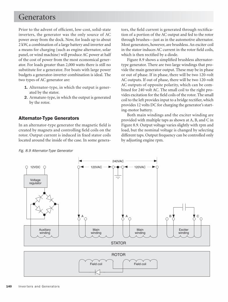
140 Inver ters and Generators
Prior to the advent of efficient, low-cost, solid-stateinverters, the generator was the only source of ACpower away from the dock. Now, for loads up to about2 kW, a combination of a large battery and inverter anda means for charging (such as engine alternator, solarpanel, or wind machine) will produce AC power at halfof the cost of power from the most economical gener-ator. For loads greater than 2,000 watts there is still nosubstitute for a generator. For boats with large powerbudgets a generator-inverter combination is ideal. Thetwo types of AC generator are:
1. Alternator-type, in which the output is gener-ated by the stator.
2. Armature-type, in which the output is generatedby the rotor.
Alternator-Type Generators In an alternator-type generator the magnetic field iscreated by magnets and controlling field coils on therotor. Output current is induced in fixed stator coilslocated around the inside of the case. In some genera-
Generators
tors, the field current is generated through rectifica-tion of a portion of the AC output and fed to the rotorthrough brushes—just as in the automotive alternator.Most generators, however, are brushless. An exciter coilin the stator induces AC current in the rotor field coils,which is then rectified by a diode.
Figure 8.9 shows a simplified brushless alternator-type generator. There are two large windings that pro-vide the main generator output. These may be in phaseor out of phase. If in phase, there will be two 120-voltAC outputs. If out of phase, there will be two 120-voltAC outputs of opposite polarity, which can be com-bined for 240 volt AC. The small coil to the right pro-vides excitation for the field coils of the rotor. The smallcoil to the left provides input to a bridge rectifier, whichprovides 12 volts DC for charging the generator’s start-ing-motor battery.
Both main windings and the exciter winding areprovided with multiple taps as shown at A, B, and C inFigure 8.9. Output voltage varies slightly with rpm andload, but the nominal voltage is changed by selectingdifferent taps. Output frequency can be controlled onlyby adjusting engine rpm.
Fig. 8.9 Alternator-Type Generator
Voltageregulator
12VDC
A B CA
Mainwinding
Auxiliarywinding
Mainwinding
Exciterwinding
120VAC 120VAC
240VAC
Field coil Field coil
STATOR
ROTOR

141Generators
Armature-Type Generators All generators and alternators rely on the fact that anelectric current is induced in either a moving wire in amagnetic field or a stationary wire in a magnetic fieldthat is changing in intensity.
In an armature-type generator, the magnetic field iscreated by a controlling field current flowing throughfixed coils that are placed around the stator (station-ary coil). The stator is anchored to the outside case ofthe generator.
Output current is induced in multiple coils woundon the rotor, which is driven at a constant 3,600 rpm(3,000 rpm in 50 Hz European models) by the speedgovernor of the generator’s engine. Large-capacity sliprings and brushes transfer the large output currentsfrom the moving rotor to the generator-output termi-nals. The output of the generator is sinusoidal in waveform.
The small DC field current is usually taken from arectifier bridge connected across a pair of output ter-minals. To get around the chicken-or-egg dilemma ofrequiring a stator field in order to begin generating cur-
rent, the stator magnets are designed to retain a degreeof permanent magnetism. A few generators solve thesame problem by taking the current for the statorwindings directly from the ship’s batteries.
Generators with a single 120-volt AC output gener-ally have two brushes, as shown in Figure 8.10. Onebrush/terminal is hot (black conductor); the otherbrush/terminal is neutral (white conductor) and isconnected to the case of the generator and to ship’sground via the green grounding conductor. Note thatsingle-voltage European versions produce 240 volts ACrather than 120 volts AC.
Generators having both 120-volt AC output and240-volt AC output have either three or four brushes.
Figure 8.11 shows a four-brush generator. Brushes 2and 3 (neutral) are tied together to the case and toship’s ground. Brushes 1 and 4 are hot. The voltagesbetween brush 1 and neutral and between brush 4 andneutral are both 120 volts AC, but of opposite polarity.The voltage between brushes 1 and 4 is thus 240 voltsAC.
Field windingArmatureBrush
1 2
1 2
120 VAC
FieldArmature
2
3
4
1 2 3 4
120 VAC 120 VAC240 VAC
FieldArmature Armature
1
Fig. 8.10 Two-Brush Armature Generator Fig. 8.11 Four-Brush Armature Generator

142 Inver ters and Generators
Frequency and Voltage Regulation As you will see below, the output frequency of a gener-ator is the key indicator of its proper operation. For thisreason the importance of a frequency meter cannot beoverstated. Most generators intended for permanentinstallation are equiped with frequency meters in theircontrol panels, whether at the generator or in the ACdistribution panel. If yours does not have such a meter,you can easily construct one from a 100-microamppanel meter and a handful of inexpensive components,as shown in Figure 8.12 and in Project 3, Chapter 14.
In a pinch you can press an old-fashioned synchro-nous electric clock into service. Such a clock advancesin proportion to the frequency of its power supply: 60minutes for 60 Hertz, 50 minutes for 50 Hertz, etc. Sim-ply plug the clock into an outlet and let it run for anhour (as timed by your watch). At the end of the hourit will read the average frequency in minutes.
In both alternator- and armature-type generators,the output is taken from the output windings and thuscorresponds directly with the rotation of the rotor. Fre-quency is therefore directly proportional to rpm. Thisis why fixed-drive generators cannot be driven directlyby a boat’s propulsion system. Hydraulic drives andvariable-speed clutches are available for matching gen-erator and propulsion engine, but they are not as pop-ular as dedicated engines.
Engine rpm is controlled by a mechanical gover-nor on the engine. As the engine slows under increasingload, a centrifugal weight acts to open the throttle.Mechanical governors require an rpm deviation inorder to effect a throttle adjustment. The more fuelrequired, the larger the required deviation in rpm.Thus, generator frequency is necessarily affected by theload. Figure 8.13 shows the typical frequency versusload relationship.
Output voltage is affected by both engine rpm andoutput load. Since rpm is affected by load, we can thinkof output voltage as being affected by load. Figure 8.14shows a typical 110- to 130-volt AC variation in out-put voltage from no load to full load. Voltages greaterthan 130 volts AC shorten the lives of resistive compo-nents, such as lamp filaments and heater elements. Lowvoltages cause motors to draw excessive currents andoverheat, or not start at all.
Generators
Hot
Neutral
A
100K
6.2Vzener 1N914
1N914
10Kpot.
0.2mF
0–100µΑ
Fig. 8.12 A Simple AC-Frequency Meter
% Load0
63
62
61
60
59
Fre
quen
cy,H
z
58
20 40 60 80 10057
Fig. 8.13 Generator Frequency vs. Load
% Load0
130
125
120
115
11020 40 60 80 100
Out
putV
olta
ge
Fig. 8.14 Generator Voltage vs. Load

143Troubleshooting Generators
WARNING: The output terminals of a working generatorare protected by neither a fuse, circuit breaker, nor groundfault circuit interrupter. At 120 or 240 volts AC, contactwith a terminal and a grounded part of the vessel at thesame time could be lethal. If you are not highly versed indealing with generators, don’t attempt measurements onthe generator while it is running. As a further precau-tion, disable any remote-start circuitry.
The owner’s manuals of high-quality generatorsusually contain extensive maintenance and trou-bleshooting guides for the specific model. If yoursdoesn’t, purchase a copy of the shop manual, which willhave the guides.
The troubleshooting guide included here is generaland not intended to replace a manufacturer’s guide.
Most generators have sealed bearings, which requireno lubrication. This does not include the generatorengine, which must be maintained to the same degreeas the boat’s propulsion engine. Crankcase oil shouldbe changed every 100 hours of operation and just priorto any extended layup.
If the boat is in the north and the generator is notremoved from the boat, the engine will require win-terization, as well. If the engine is gasoline-fueled, thespark plugs should be replaced every year.
If the generator contains brushes, check the brushesfor excessive wear (more than 50%) and the slip ringsfor burning and pitting. Replace worn brushes withexact replacements from the manufacturer and followthe directions for seating the new brushes.
The troubleshooting guide applies to both arma-ture- and alternator-type generators. You will need tomeasure output AC volts, AC amps, and frequency. Aproper generator installation should include AC volts,AC amps, and frequency panel meters in the AC dis-tribution panel. For smaller generators use a multime-ter to measure volts and amps. If you don’t have a fre-quency meter, purchase one or build the one in Project3, Chapter 14.
Troubleshooting Guide
Voltage Erratic
STEP 1. Check the brushes for wear. Replace ifmore than 50% worn.STEP 2. Check slip rings for burning and/or pit-ting (requires services of a machine shop).
Voltage High (over 130 volts)
STEP 1. Check the frequency for normal range (57to 63 Hertz).STEP 2. Adjust the voltage regulator if possible.STEP 3. Have the voltage regulator checked. Con-sult the manual for terminal changes.
Voltage Low (below 110 volts)
STEP 1. Check the voltage at the generator termi-nals. If OK, the problem is voltage drop in connec-tors or conductors.STEP 2. If the voltage is OK initially, then drops,check the temperature of the voltage regulator. Itshould be cool enough to touch.STEP 3. Adjust the voltage regulator if possible.STEP 4. Consult manual for terminal change.
Frequency Erratic
STEP 1. Check for loads that cycle on and off.STEP 2. If erratic with no load connected, check theengine governor.
Frequency High (over 63 Hertz)
STEP 1. Adjust the engine governor and clean andlubricate its linkage.STEP 2. Consult the engine manual.
Frequency Low (below 57 Hertz)
STEP 1. Reduce the load. If frequency increases tonormal range, the generator is overloaded.STEP 2. Adjust engine governor and clean andlubricate linkage; consult manual.
Troubleshooting Generators

AC Standards and Practices
144
CHAPTER 9
Boatground
Boatground
Galvanic current
Common green wire
Dock float
Black
White
Green
Black
White
Green
Copyright © 1993, 2006 by Charlie Wing. Click here for terms of use.

145
As with Chapter 6, its DC equivalent, this chapteris essentially an amplification of the ABYC stan-dards for AC power aboard boats.
We start with sources of AC power: shore power,generators, and inverters, all of which feed the AC mainpanelboard.
Two primary AC safety considerations are ground-ing (including ground faults) and overcurrent protec-tion.
Load calculations and ampacity tables allow us tosize the overcurrent protection and to select both theapproved wire and cable and receptacles for the appli-cation.
The probability of moisture, salt, and vibration, aswell as the possibility of gasoline vapors, mandate stan-dards for the installation of conductors.
As with DC wiring, the issue of galvanic protectionand grounding raises the question of what to do withthe green wire. The two solutions—isolating diodesand isolation transformers—are incorporated intoABYC-approved shore-power circuits.
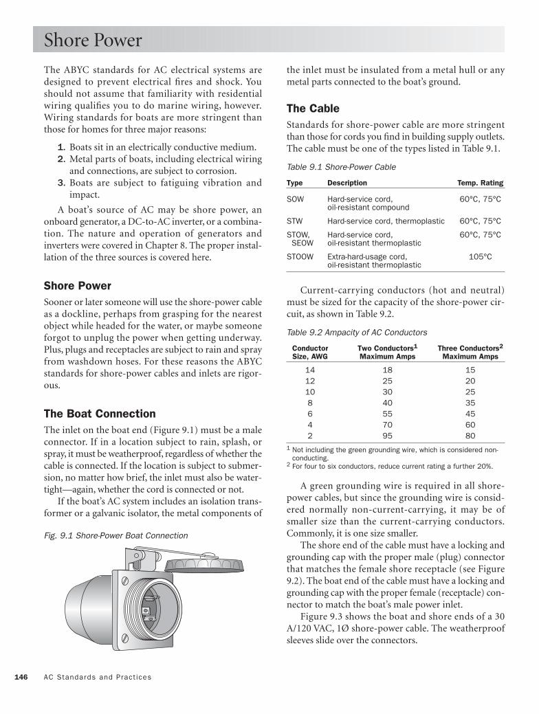
146 AC Standards and Pract ices
The ABYC standards for AC electrical systems aredesigned to prevent electrical fires and shock. Youshould not assume that familiarity with residentialwiring qualifies you to do marine wiring, however.Wiring standards for boats are more stringent thanthose for homes for three major reasons:
1. Boats sit in an electrically conductive medium.2. Metal parts of boats, including electrical wiring
and connections, are subject to corrosion.3. Boats are subject to fatiguing vibration and
impact.
A boat’s source of AC may be shore power, anonboard generator, a DC-to-AC inverter, or a combina-tion. The nature and operation of generators andinverters were covered in Chapter 8. The proper instal-lation of the three sources is covered here.
Shore PowerSooner or later someone will use the shore-power cableas a dockline, perhaps from grasping for the nearestobject while headed for the water, or maybe someoneforgot to unplug the power when getting underway.Plus, plugs and receptacles are subject to rain and sprayfrom washdown hoses. For these reasons the ABYCstandards for shore-power cables and inlets are rigor-ous.
The Boat Connection The inlet on the boat end (Figure 9.1) must be a maleconnector. If in a location subject to rain, splash, orspray, it must be weatherproof, regardless of whether thecable is connected. If the location is subject to submer-sion, no matter how brief, the inlet must also be water-tight—again, whether the cord is connected or not.
If the boat’s AC system includes an isolation trans-former or a galvanic isolator, the metal components of
Shore Power
the inlet must be insulated from a metal hull or anymetal parts connected to the boat’s ground.
The Cable Standards for shore-power cable are more stringentthan those for cords you find in building supply outlets.The cable must be one of the types listed in Table 9.1.
Table 9.1 Shore-Power Cable
Type Description Temp. Rating
SOW Hard-service cord, 60°C, 75°Coil-resistant compound
STW Hard-service cord, thermoplastic 60°C, 75°C
STOW, Hard-service cord, 60°C, 75°C SEOW oil-resistant thermoplastic
STOOW Extra-hard-usage cord, 105°Coil-resistant thermoplastic
Current-carrying conductors (hot and neutral)must be sized for the capacity of the shore-power cir-cuit, as shown in Table 9.2.
Table 9.2 Ampacity of AC Conductors
Conductor Two Conductors1 Three Conductors2
Size, AWG Maximum Amps Maximum Amps
14 18 15 12 25 20 10 30 258 40 35 6 55 45 4 70 60 2 95 80
1 Not including the green grounding wire, which is considered non-conducting.
2 For four to six conductors, reduce current rating a further 20%.
A green grounding wire is required in all shore-power cables, but since the grounding wire is consid-ered normally non-current-carrying, it may be ofsmaller size than the current-carrying conductors.Commonly, it is one size smaller.
The shore end of the cable must have a locking andgrounding cap with the proper male (plug) connectorthat matches the female shore receptacle (see Figure9.2). The boat end of the cable must have a locking andgrounding cap with the proper female (receptacle) con-nector to match the boat’s male power inlet.
Figure 9.3 shows the boat and shore ends of a 30A/120 VAC, 1Ø shore-power cable. The weatherproofsleeves slide over the connectors.
Fig. 9.1 Shore-Power Boat Connection

147Shore Power
Boat end
Shore end
Fig. 9.3 30 A/120 VAC Shore-Power Cable
100A, 120/240VPin and sleeve3 pole, 4 wire
15A, 120VStraight blade2 pole, 3 wire
20A, 120VStraight blade2 pole, 3 wire
20A, 120VLocking
2 pole, 3 wire
30A, 120VLocking
2 pole, 3 wire
50A, 120VLocking
2 pole, 3 wire
50A, 120/240VLocking
3 pole, 4 wire
30A, 120/208V 3ØYLocking
4 pole, 5 wire
100A, 120/208V 3ØYPin and sleeve4 pole, 5 wire
120 Volts
240 and 208 Volts
Receptacle
Plug
Receptacle
Plug
Receptacle
Plug
Receptacle
Plug
Receptacle
Plug
Receptacle
Plug
Receptacle
Plug
Receptacle
Plug
Receptacle
Plug
G G
G G
W W
W W
G
W
G
W
G
W
G
W
WG
W G
W
WG
G
W
G
Y X
XZ
Y
G
Y
X
X
Z
WY
G
W
YX
G
W
XY G
WZ
YX
G
WZ
YX
Fig. 9.2 Matching AC Plugs and Receptacles (U.S.)

148 AC Standards and Pract ices
Transfer Switch Connections to shore power, onboard generators, andinverters must be such that no more than one sourcecan be connected to a circuit simultaneously. Switchingbetween power sources must be made with a transferswitch, which prevents arc-over between the contacts ofthe different sources.
Grounded Neutral Boat AC systems use a grounded neutral, as do residen-tial systems. Where the neutral (white conductor) andgrounding (green or bare conductor) are connected iscritical. The neutral (white) must be grounded (con-nected to the green or bare conductor) only at thepower source: an onboard generator or inverter, the sec-ondary of an isolation or polarization transformer, orthe shore-power receptacle.
Figure 9.4 shows a system consisting of shorepower, onboard generator, and inverter. A two-poletransfer switch selects the power source. Note that theneutral (white) and grounding (green) wires are con-
Generator and Inverter Sources
nected at the generator, at the inverter, and (not shown)at the shore-end source.
A galvanic isolator serves to block stray current inthe shore-power grounding wire. Thus, regardless ofthe source of power, the neutral is grounded only at itssource. Further, the neutral and grounding conductorsare always maintained at boat ground, which is criticalfor the safety of anyone on board.
AmpacityAn onboard generator or inverter must be rated to sup-ply the entire load, as calculated later, unless the sys-tem is designed to isolate certain loads from connec-tion.
In either case, the feed conductors from the gener-ator or inverter must be of sufficient ampacity to carrythe maximum rated output. In addition, the generatoror inverter output must be protected at its output withan overcurrent device, rated at no more than 120% ofthe rated output, unless the generator or inverter is self-limiting to the same degree.
W
G
B
G W B
G
W
B
Galvanicisolator
Inverter Battery
Green
White
Black
O
Gen
Shore Inv
To engine negative terminal (boat ground)
Main shore-power disconnectcircuit breaker
To branch circuitprotective devices
Shore-power cable
+
–
+
–
Auxiliarygenerator
Fig. 9.4 Typical Use of the Transfer Switch

149Main Panelboard
All AC systems must have a main panelboard, whichmay (it usually does) also serve as the AC distributionpanel. The panelboard must be easily accessible andeither weatherproof or in a location protected from theweather.
The panelboard must be clearly and permanentlymarked with the system voltage and frequency. Twocommon markings are “120VAC” and “120V-60Hz.” Ifthere are either AC motors or an AC generator aboard,the panelboard should also include an AC voltmeter. Itis recommended that the voltmeter display upper andlower operating voltage limits.
The main panelboard should also contain a shore-power polarity indicator that warns of reversed polar-ity in the shore-power connection with either a contin-uous sound or light. A polarity indicator must beinstalled if:
1. Any of the boat’s branch circuits have overcur-rent protection in the ungrounded conductoronly, or
2. Polarity is critical to the operation of any of theAC devices on the boat.
A polarity indicator is not needed, however, if theshore power feeds through an isolation transformer,since the transformer acts as a separate source of poweron the boat, and its output conductors are permanentlywired.
In order to limit current on the normally non-current-carrying green grounding wire, the impedance
of polarity indication devices must be at least 25k ohms.Figure 9.5 shows a simple polarity-indicating circuit
that satisfies the 25k ohm criterion. A green light indi-cates correct polarity (voltage between the hot andneutral conductors). A red light indicates incorrectpolarity (either neutral or grounding conductor hot).
Plug-in polarity indicators, no larger than a three-prong adapter, are available at hardware stores foraround $5. If your AC panel doesn’t have a built-inpolarity indicator, one of these devices can be used toquickly check for damaging reverse polarity whenestablishing a shore-power connection. Such a devicedoes not satisfy the ABYC requirement, however.
A permanent waterproof warning placard must bedisplayed prominently at all shore-power inlets. Figure9.6 shows the wording suggested by the ABYC.
Main Panelboard
Hot (black)
Neutral (white)
Ground (green)
N1Green
N1
N2Red
R1 R1
Fig. 9.5 A Simple Polarity-Indicating Circuit (see Project1, Chapter 14)
WARNINGTo minimize shock and fire hazards:
1. Turn off the boat's shore connection switch before connecting or disconnecting shore cable.
2. Connect shore-power cable at the boat first.3. If polarity warning indicator is activated,
immediately disconnect cable.4. Disconnect shore-power cable at shore outlet first.
5. Close shore-power inlet cover tightly.
DO NOT ALTER SHORE-POWER CABLE CONNECTORS
Fig. 9.6 ABYC Suggested Wording for Shore-Power Connection

150 AC Standards and Pract ices
Instructions The ABYC suggests a method for determining the min-imum sizes of AC panelboards, supply conductors, andAC power sources. The total load may be supplied by:
1. A single shore-power cable of required ampacity.2. Multiple shore-power cables, provided each inlet
is marked with volts, amps, phase (if 3Ø), andthe load it serves.
3. One or more onboard generators of continuousrating equal to the load.
4. Shore power plus generators and inverters ofcombined capacity equal to the load, providedthe loads connected to each are isolated.
Table 9.3 is a form that follows the ABYC-recom-mended procedure for calculating AC loads. As youread the instructions below, you may also find it help-ful to refer to Table 9.5, the completed example.
Lighting and Small Appliances (Lines 1–7)
Lighting includes all AC-powered lights on the boat.Small appliances are those used in the galley and diningareas that have power cords and plugs, such as blenders,mixers, and toasters.
LINE 1. Add the total square feet of all of the livingareas on the boat, not counting storage and enginespaces, and multiply by 2.0.LINE 2. Multiply the number of 20-amp circuitsused for small appliances in the galley and diningareas by 1,500.LINE 3. Add Lines 1 and 2.LINE 4. Subtract 2,000 from Line 3, and multiplyby 0.35 (enter 0 if negative).LINE 5. Add Lines 3 and 4.LINE 6. Divide Line 5 by the system voltage (either120 or 240).LINE 7. If your shore-power inlet is 120 VAC, enterLine 6 in Column A. From this point on, use onlythe left-hand (Column A) lines. If instead you havea 240-volt AC system that splits into two onboard120 VAC branches, enter half of Line 6 in ColumnsA and B. From this point on, you will have to entervalues in Columns A and B separately, dependingon which branch of the 240 circuit the load is on.
AC Load Calculations
Motors and Heaters (Lines 8–12)
For Lines 8 through 27, you will need the amps listedon the nameplates of each piece of equipment. Thenameplate is usually found on the backside of theequipment.
LINE 8. Add and enter the total amps for all fans.LINE 9. Total the amps for all air conditioners. Ifthere are two units, enter the larger number. If thereare three or more units, multiply the total by 0.75. Ifthe total is less than Line 10, leave Line 9 blank.LINE 10. Total the amps for electric, gas, and oilheaters. If this total is less than the total in the pre-vious step (before multiplying by 0.75), leave Line10 blank.LINE 11. Enter 25% of the nameplate amps for thelargest motor in any of the appliances involved inLines 8 through 10.LINE 12. Enter total of Lines 8 through 11.
Fixed Appliances (Lines 13–28)
LINES 13–27. For each of the appliances shown,multiply the amps listed on the nameplates by theuse factors listed after the appliance name. If theunit is a 240-volt appliance, enter the result in bothColumns A and B.LINE 28. Enter the total of Lines 13 through 27, butif there are more than three appliances listed inLines 13 through 27, first multiply Line 28 by 0.6.
Free-Standing Range (Lines 29–31)
LINE 29. A free-standing range is one that containsboth surface burners and an oven. First, read thewatts listed on the range nameplate. Enter the cor-responding “load watts” from Table 9.4.LINE 30. Enter the range voltage (from the name-plate).LINE 31. Divide Line 29 by Line 30 and enter valuein both Columns A and B.
Total AC Load (Line 32)
LINE 32. Total Lines 7, 12, 28, and 31 separately forColumns A and B. The Total AC Load in Amps isthe larger of A and B.

151AC Load Calculat ions
Line Loads Column A Column B
LIGHTING AND SMALL APPLIANCES
1. Lighting and receptacles: Living area sq.ft. × 2 __________ __________
2. Small appliances: number of 20-amp circuits × 1,500 __________ __________
3. Line 1 + Line 2 __________ __________
4. (Line 3 – 2,000) × 0.35 (Enter 0 if less than 0) __________ __________
5. Line 3 + Line 4 __________ __________
6. Line 5/System voltage (either 120 or 240) __________ __________
7. If 120 VAC, enter Line 6 in Column A; if 240 VAC, enter 50% of Line 6 in both A and B __________ __________
MOTORS AND HEATERS (total nameplate amps)
8. Exhaust and supply fans __________ __________
9. Air conditioners (If two, enter larger number; if three or more, enter 75% of total; omit if less than Line 10) __________ __________
10. Heaters (If two, enter larger number) (If figure is less than Line 9, enter 0) __________ __________
11. 25% of largest motor in Lines 8–10 __________ __________
12. Total of Lines 8–11 __________ __________
FIXED APPLIANCES (nameplate amps)
13. Disposal × 0.1 __________ __________
14. Water heater × 1.0 __________ __________
15. Wall oven × 0.75 __________ __________
16. Stovetop cooking unit × 0.75 __________ __________
17. Refrigerator × 1.0 __________ __________
18. Freezer × 1.0 __________ __________
19. Ice maker × 0.5 __________ __________
20. Dishwasher × 0.25 __________ __________
21. Clothes washer × 0.25 __________ __________
22. Clothes dryer × 0.25 __________ __________
23. Trash compactor × 0.1 __________ __________
24. Air compresser × 0.1 __________ __________
25. Battery charger × 1.0 __________ __________
26. Vacuum system × 0.1 __________ __________
27. Sum of other fixed appliances __________ __________
28. Total of Lines 13–27; if more than three fixed appliances, × 0.6 __________ __________
FREE-STANDING RANGE
29. Load watts from Table 9.4 __________ __________
30. Nameplate volts (either 120 or 240) __________ __________
31. Line 29 divided by Line 30 __________ __________
32. Sum of Lines 7, 12, 28, and 31; TOTAL is larger of A and B __________ __________
Table 9.3 ABYC AC Load Calculation Form

152 AC Standards and Pract ices
ExampleUse Table 9.5 to calculate the 120 VAC load for a boatwith 240 square feet of enclosed space (not includingengine compartment or chain locker), one 20-ampsmall appliance circuit, and:
• 50-watt (0.4 amp) ventilation fan • 1,500-watt (12 amp) water heater • 85-watt (0.7 amp) refrigerator • 120-watt (1 amp) air compressor • 420-watt (3.5 amp) battery charger
Lighting and Small Appliances (Lines 1–7)
The lighting load is 2 × 240 square feet = 480 watts,which we enter on Line 1.
The small appliance load for one 20-amp circuit is 1 ×1,500 watts = 1,500 watts, which we enter on Line 2.
The sum of lines 1 and 2 is 1,980 watts, which is lessthan 2,000 watts, so we enter 1,980 watts on Line 3 and0 watts on Line 4.
We divide 1,980 watts by 120 volts to get 16.5 amps.Since 120-volt shore power only has one branch, weenter the 16.5 amps on Line 7A.
Motors and Heaters (Lines 8–12)
We have only one motor—the 0.4-amp fan, which weenter on Line 8. Adding 25%, we get 0.5 amp, whichwe enter on Line 12A.
AC Load Calculations
Fixed Appliances (Lines 13–28)
Our fixed appliances include the 12-amp water heater,0.7-amp refrigerator, 3.5-amp battery charger, and 1-amp air compressor. The first three have a duty factorof 1.0, so we enter their amps directly. The compressorhas a duty factor of only 0.10, so we enter 0.10 × 1.0amp = 0.1 amp on Line 24A.
Adding Lines 13 through 27 we get 16.3 amps. Sincethere are more than three fixed appliances, we multi-ply the sum by the factor 0.60 and enter the result, 9.8,on Line 28.
Total AC Load (Line 32)
Adding Line 7 (16.5 amps), Line 12 (0.5 amp), Line 28(9.8 amps), and Line 31 (0.0 amps), we get 26.8 amps.Since our system has only a single phase and, thus, asingle branch, our total AC load for sizing the mainAC panelboard is 26.8 amps. Rounding up, we’ll call it30 amps.
Table 9.4 Load Watts for Free-Standing Ranges(For use in Table 9.5, Line 29)
Nameplate Watts Load Watts
0–10,000 80%10,001–12,500 8,00012,501–13,500 8,40013,501–14,500 8,80014,501–15,500 9,20015,501–16,500 9,600

153AC Load Calculat ions
Line Loads Column A Column B
LIGHTING AND SMALL APPLIANCES
1. Lighting and receptacles: Living area sq.ft. × 2 __________ __________
2. Small appliances: number of 20-amp circuits × 1,500 __________ __________
3. Line 1 + Line 2 __________ __________
4. (Line 3 – 2,000) × 0.35 (Enter 0 if less than 0) __________ __________
5. Line 3 + Line 4 __________ __________
6. Line 5/System voltage (either 120 or 240) __________ __________
7. If 120 VAC, enter Line 6 in Column A; if 240 VAC, enter 50% of Line 6 in both A and B __________ __________
MOTORS AND HEATERS (total nameplate amps)
8. Exhaust and supply fans __________ __________
9. Air conditioners (If two, enter larger number; if three or more, enter 75% of total; omit if less than Line 10) __________
10. Heaters (If two, enter larger number) (If figure is less than Line 9, enter 0) __________ __________
11. 25% of largest motor in Lines 8–10 __________ __________
12. Total of Lines 8–11 __________ __________
FIXED APPLIANCES (nameplate amps)
13. Disposal × 0.1 __________ __________
14. Water heater × 1.0 __________ __________
15. Wall oven × 0.75 __________ __________
16. Stovetop cooking unit × 0.75 __________ __________
17. Refrigerator × 1.0 __________ __________
18. Freezer × 1.0 __________ __________
19. Ice maker × 0.5 __________ __________
20. Dishwasher × 0.25 __________ __________
21. Clothes washer × 0.25 __________ __________
22. Clothes dryer × 0.25 __________ __________
23. Trash compactor × 0.1 __________ __________
24. Air compresser × 0.1 __________ __________
25. Battery charger × 1.0 __________ __________
26. Vacuum system × 0.1 __________ __________
27. Sum of other fixed appliances __________ __________
28. Total of Lines 13–27; if more than three fixed appliances, × 0.6 __________ __________
FREE-STANDING RANGE
29. Load watts from Table 9.4 __________ __________
30. Nameplate volts (either 120 or 240) __________ __________
31. Line 29 divided by Line 30 __________ __________
32. Sum of Lines 7, 12, 28, and 31; TOTAL is larger of A and B __________ __________
Table 9.5 ABYC AC Load Calculation Form (filled-out example)
480
1500
1980
0
1980
16.5
16.5
0.4
0.1
0.5
12.0
0.7
0.1
3.5
9.8
26.8

154 AC Standards and Pract ices
Amp Ratings All fuses and circuit breakers must be rated at or lessthan the ampacity of the conductors of the circuitbeing protected. Exception: if no breaker of correctampacity is available, the breaker rating may exceed theampacity of the conductors by up to 150%.
Circuit Breaker Specifications All circuit breakers must meet the standards of eitherUL 489 or UL 1077, be of the manual-reset type (exceptif integral to a piece of equipment), and be of the trip-free type (cannot be held closed while the overcurrentcondition persists).
Main Supply Protection Specifications for overcurrent protection of the mainsupply conductors include:
1. The shore-power feeder conductors should beprotected by multi-pole breakers. In a 120 VACsystem the breakers should protect both theungrounded (black) and the neutral (white)conductors. In any system containing either 240VAC or 208 VAC, there should be breakers in allof the ungrounded conductors. Note that thegreen grounding conductor is never interrupted.
2. If there are isolation or polarization transform-ers in the shore-power feed, primaries should beprotected by a circuit breaker that opens bothprimary feeders simultaneously and that is ratedat no more than 125% of the primary rating. Ifthe secondary provides 120/240 VAC, it alsoshould be protected by a circuit breaker thatopens both secondary feeders simultaneouslyand that is rated at no more than 125% of therated secondary current of the transformer.
3. The maximum unprotected conductor lengthfrom boat inlet connector to circuit breakermust not exceed 10 feet. If the length is greaterthan 10 feet, add additional slow-blow fuses orbreakers within 10 feet of the inlet. If additionalfuses or circuit breakers are provided, they mustbe larger, but not more than 125% larger, thanthe main shore-power disconnect breaker.
4. The maximum unprotected conductor lengthfrom an AC generator must be less than 7 inches.However, up to 40 inches is allowed if the con-ductor is protected by a sheath or enclosure.
Overcurrent Protection
Branch-Circuit Protection Branch circuit breakers and fuses should be rated at orless than the ampacity of the smallest current-carryingconductor in the circuit. If there is no matching breakeror fuse rating, the next larger may be used, provided itdoesn’t exceed 150% of conductor ampacity.
For boats wired with 120 VAC, 1Ø, both current-carrying conductors (hot and neutral) must be pro-tected by a pair of simultaneous-trip circuit breakers.Exception: the ungrounded conductor alone may beprotected, provided:
1. The entire system is polarized, including lightingfixtures, and there is a polarity indicator betweenthe shore-power inlet and the main circuitbreakers, or
2. The neutral and grounding conductors are con-nected at the secondary of an isolation or polar-ization transformer.
All motors must be protected by either an overcur-rent or a thermal device unless they do not overheat,even when the motor is stalled (rotor locked).
Fuse or Breaker Location The fuses or circuit breakers for a circuit must beplaced at its power source, except:
1. If impractical, within 7 inches of the source.2. If impractical within 7 inches, then within 40
inches, provided the conductor is contained in aprotective sheath or enclosure.
Ground Fault Protection
GFCI Breakers
GFCI breakers must meet the same requirements as cir-cuit breakers of the same rating. They may be used toprotect individual branch circuits, or they may protect agroup of associated circuits. Like other circuit breakers,they are permitted to interrupt only the ungroundedconductor, provided the system is polarized and has apolarity indicator, the system has an isolation or polar-ization transformer, or the system is 120/240 VAC.
GFCI Receptacles
GFCI receptacle devices must be two-pole and meetall of the requirements of standards UL 943 and UL498. They may protect either a single receptacle or mul-tiple receptacles in the same circuit.

155Approved Wire and Cable
No conductor may be smaller than 16 AWG, except 18AWG inside panelboards and equipment enclosures,serving DC electronics at less than 1 amp, as less than7-inch panelboard pigtails, and extending less than 30inches outside a sheathed bundle. The temperature rat-ings of all conductors and flexible cords should be atleast 140°F (60°C), except 167°F (75°C) in enginespaces. Individual conductor insulations must be ratedat 600 volts minimum. Flexible cords may be rated at aminimum of 300 volts.
Conductors must be one of the types listed in Table9.6. Flexible cords must be one of the types listed inTable 9.7. Both conductors and flexible cords must alsobe of the stranding as shown in Table 9.8.
The ABYC-recommended color code for AC wiringis shown in Table 9.9.
Table 9.6 Acceptable Conductor Types for AC Wiring
Damp Oil Extra-Hard Hard Type Location Resistant Usage Usage
SE, SEW X XSEO, SEOW X X XSJ, SJW X X SJE, SJEW X X SJEO, SJEOW X X X SJO, SJOW X X X SJOO, SJOOW X X X SJT, SJTW X X SJTO, SJTOW X X X SJTOO, SJTOOW X X X SO, SOW X X XST, STW X XSTO, STOW X X XSTOO, STOOW X X X
Table 9.7 Acceptable Flexible Cord Types for AC Wiring
Type Description
SO, SOW Hard-Service Cord, Oil Resistant ST, STW Hard-Service Cord, Thermoplastic STO, STOW Hard-Service Cord, Oil Resistant,
Thermoplastic SEO, SEOW Hard-Service Cord, Oil Resistant,
Thermoplastic SJO, SJOW, Junior Hard-Service Cord, Oil Resistant SJTW
SJT, SJTW Hard-Service Cord, Thermoplastic SJTO, SJTOW Hard-Service Cord, Oil Resistant,
Thermoplastic
Table 9.8 Minimum AC Conductor Stranding
Conductor Minimum Minimum Minimum StrandsGauge CM for AWG CM for SAE Type II1 Type III2
18 1,620 1,537 16 – 16 2,580 2,336 19 26 14 4,110 3,702 19 41 12 6,530 5,833 19 65 10 10,380 9,343 19 105 8 16,510 14,810 19 168 6 26,240 25,910 37 266 4 41,740 37,360 49 420 2 66,360 62,450 127 665 1 83,690 77,790 127 836 0 105,600 98,980 127 1,064
2/0 133,100 125,100 127 1,323 3/0 167,800 158,600 259 1,666 4/0 211,600 205,500 418 2,107
1 Conductors with at least Type II stranding to be used for general-purpose boat wiring.
2 Conductors with Type III stranding to be used where frequent flex-ing is expected.
Table 9.9 Color Code for AC Wiring
Conductor Colors (Preferred First)
Ungrounded Black or Brown
Grounded Neutral White or Light Blue
Grounding Green, Green with Yellow Stripe
Additional Ungrounded Red, Blue, Orange
Black with Red Stripe
Black with Blue Stripe
Black with Orange Stripe
AmpacityThe minimum ampacities of AC current-carrying con-ductors are shown in Tables 9.10 through 9.15 on thefollowing pages.
Approved Wire and Cable

156 AC Standards and Pract ices
Ampacity TablesTable 9.10 Allowable Amperage of No More Than Two Bundled Conductors(Adapted from ABYC Standard E-11, Table VII-A)
Temperature Rating of Conductor Insulation
Size 60°C 75°C 80°C 90°C 105°C 125°C 200°C AWG 140°F 167°F 176°F 194°F 221°F 257°F 392°F
Outside Engine Spaces
18 10 10 15 20 20 25 25
16 15 15 20 25 25 30 35
14 20 20 25 30 35 40 45
12 25 25 35 40 45 50 55
10 40 40 50 55 60 70 70
8 55 65 70 70 80 90 100
6 80 95 100 100 120 125 135
4 105 125 130 135 160 170 180
2 140 170 175 180 210 225 240
1 165 195 210 210 245 265 280
1/0 195 230 245 245 285 305 325
2/0 225 265 285 285 330 355 370
3/0 260 310 330 330 385 410 430
4/0 300 360 385 385 445 475 510
Inside Engine Spaces
18 5 7 11 16 17 22 25
16 8 11 15 20 21 26 35
14 11 15 19 24 29 35 45
12 14 18 27 32 38 44 55
10 23 30 39 45 51 62 70
8 31 48 54 57 68 80 100
6 46 71 78 82 102 111 135
4 60 93 101 110 136 151 180
2 81 127 136 147 178 200 240
1 95 146 163 172 208 235 280
1/0 113 172 191 200 242 271 325
2/0 130 198 222 233 280 316 370
3/0 150 232 257 270 327 364 430
4/0 174 270 300 315 378 422 510

157Ampacity Tables
Table 9.11 Allowable Amperage of Three Bundled Conductors (Adapted from ABYC Standard E-11, Table VII-B)
Temperature Rating of Conductor Insulation
Size 60°C 75°C 80°C 90°C 105°C 125°C 200°C AWG 140°F 167°F 176°F 194°F 221°F 257°F 392°F
Outside Engine Spaces
18 7 7 10 14 14 17 17
16 10 10 14 17 17 21 24
14 14 14 17 21 24 28 31
12 17 17 24 28 31 35 38
10 28 28 35 38 42 49 49
8 38 45 49 49 56 63 70
6 56 66 70 70 84 87 94
4 73 87 91 94 112 119 126
2 98 119 122 126 147 157 168
1 115 136 147 147 171 185 196
1/0 136 161 171 171 199 213 227
2/0 157 185 199 199 231 248 259
3/0 182 217 231 231 269 287 301
4/0 210 252 269 269 311 332 357
Inside Engine Spaces
18 4 5 8 11 11 15 17
16 6 7 10 14 14 18 24
14 8 10 13 17 20 24 31
12 10 13 19 23 26 31 38
10 16 21 27 31 35 43 49
8 22 34 38 40 47 56 70
6 32 49 54 57 71 77 94
4 42 65 71 77 95 105 126
2 56 89 95 103 125 140 168
1 67 102 114 120 145 165 196
1/0 79 120 133 140 169 190 227
2/0 91 139 155 163 196 221 259
3/0 105 162 180 189 229 255 301
4/0 121 189 210 221 264 295 357

158 AC Standards and Pract ices
Ampacity TablesTable 9.12 Allowable Amperage of Four to Six Bundled Conductors(Adapted from ABYC Standard E-11, Table VII-C)
Temperature Rating of Conductor Insulation
Size 60°C 75°C 80°C 90°C 105°C 125°C 200°C AWG 140°F 167°F 176°F 194°F 221°F 257°F 392°F
Outside Engine Spaces
18 6 6 9 12 12 15 15
16 9 9 12 15 15 18 21
14 12 12 15 18 21 24 27
12 15 15 21 24 27 30 33
10 24 24 30 33 36 42 42
8 33 39 42 42 48 54 60
6 48 57 60 60 72 75 81
4 63 75 78 81 96 102 108
2 84 102 105 108 126 135 144
1 99 117 126 126 147 159 168
1/0 117 138 147 147 171 183 195
2/0 135 159 171 171 198 213 222
3/0 156 186 198 198 231 246 258
4/0 180 216 231 231 267 285 306
Inside Engine Spaces
18 3 4 7 9 10 13 15
16 5 6 9 12 12 16 21
14 7 9 11 14 17 21 27
12 8 11 16 19 23 26 33
10 13 18 23 27 30 37 42
8 19 29 32 34 40 48 60
6 27 42 46 49 61 66 81
4 36 56 60 66 81 90 108
2 48 76 81 88 107 120 144
1 57 87 98 103 125 141 168
1/0 67 103 114 120 145 162 195
2/0 78 119 133 140 168 189 222
3/0 90 139 154 162 196 218 258
4/0 104 162 180 189 227 253 306

159Ampacity Tables
Table 9.13 Allowable Amperage of Seven to 24 Bundled Conductors(Adapted from ABYC Standard E-11, Table VII-D)
Temperature Rating of Conductor Insulation
Size 60°C 75°C 80°C 90°C 105°C 125°C 200°C AWG 140°F 167°F 176°F 194°F 221°F 257°F 392°F
Outside Engine Spaces
18 5 5 7 10 10 12 12
16 7 7 10 12 12 15 17
14 10 10 12 15 17 20 22
12 12 12 17 20 22 25 27
10 20 20 25 27 30 35 35
8 27 32 35 35 40 45 50
6 40 47 50 50 60 62 67
4 52 62 65 67 80 85 90
2 70 85 87 90 105 112 120
1 82 97 105 105 122 132 140
1/0 97 115 122 122 142 152 162
2/0 112 132 142 142 165 177 185
3/0 130 155 165 165 192 205 215
4/0 150 180 192 192 222 237 255
Inside Engine Spaces
18 2 3 5 8 8 11 12
16 4 5 7 10 10 13 17
14 5 7 9 12 14 17 22
12 7 9 13 16 19 22 27
10 11 15 19 22 25 31 35
8 16 24 27 28 34 40 50
6 23 35 39 41 51 55 67
4 30 46 50 55 68 75 90
2 40 63 68 73 89 100 120
1 47 73 81 86 104 117 140
1/0 56 86 95 100 121 135 162
2/0 65 99 111 116 140 158 185
3/0 75 116 128 135 163 182 215
4/0 87 135 150 157 189 211 255

160 AC Standards and Pract ices
Ampacity TablesTable 9.14 Allowable Amperage of 25 or More Bundled Conductors(Adapted from ABYC Standard E-11, Table VII-E)
Temperature Rating of Conductor Insulation
Size 60°C 75°C 80°C 90°C 105°C 125°C 200°C AWG 140°F 167°F 176°F 194°F 221°F 257°F 392°F
Outside Engine Spaces
18 4 4 6 8 8 10 10
16 6 6 8 10 10 12 14
14 8 8 10 12 14 16 18
12 10 10 14 16 18 20 22
10 16 16 20 22 24 28 28
8 22 26 28 28 32 36 40
6 32 38 40 40 48 50 54
4 42 50 52 54 64 68 72
2 56 68 70 72 84 90 96
1 66 78 84 84 98 106 112
1/0 78 92 98 98 114 122 130
2/0 90 106 114 114 132 142 148
3/0 104 124 132 132 154 164 172
4/0 120 144 154 151 178 190 204
Inside Engine Spaces
18 2 3 4 6 6 8 10
16 3 4 6 8 8 10 14
14 4 6 7 9 11 14 18
12 5 7 10 13 15 17 22
10 9 12 15 18 20 24 28
8 12 19 21 23 27 32 40
6 18 28 31 32 40 44 54
4 24 37 40 44 54 60 72
2 32 51 54 59 71 80 96
1 38 58 65 68 83 94 112
1/0 45 69 76 80 96 108 130
2/0 52 79 88 93 112 126 148
3/0 60 93 103 108 130 146 172
4/0 69 108 120 126 151 169 204

161Ampacity Tables
Table 9.15 Allowable Amperage of Flexible Cords1,2
(Adapted from ABYC Standard E-11, Table XIII)
Outside Engine Space Inside Engine SpaceSize, Nominal CM 30°C Ambient 50°C AmbientAWG Area Three Conductors Two Conductors Three Conductors Two Conductors
16 2,580 10 13 6 8
14 4,110 15 18 9 11
12 6,530 20 25 12 15
10 10,380 25 30 15 20
8 16,510 35 40 20 25
6 26,240 45 55 30 35
4 41,740 60 70 35 40
2 66,360 80 95 50 55
1 Current ratings are for flexible cords containing no more than three conductors. For four to six conductors, reduce ampacity to 80%.2 Shore-power cables rated at 86°F (30°C).

162 AC Standards and Pract ices
Note that the conductor specifications and wiring tech-niques for DC and AC systems are nearly identical. Someof the illustrations used in Chapter 6 are repeated here tosave the reader from having to flip back and forth.
ConnectionsFabrication and installation of wiring connectionsshould not damage the conductors. Special tools (seeFigure 6.10 and discussion in Chapter 6) are availablefor making approved crimp-on connections.
All connection components (conductors, terminals,studs, washers, and nuts) should be galvanically com-patible and corrosion resistant. Specifically, aluminumand unplated steel are not appropriate for studs, nuts,and washers.
Marine connectors also differ from the more com-mon electronic-type connectors in that they mustwithstand vibration and tensile stresses. Figure 9.7shows the types of connectors approved for marine use,along with several types specifically disapproved.
Friction connectors (the blade and bullet variety inFigure 9.7) are allowed, provided they resist a 6-poundpull. The other approved connectors must resist thepulls shown in Table 9.16 for at least 1 minute.
Although not specified in the ABYC standard, pre-tinned conductors are preferred in marine use. The rea-son will be apparent when you attempt to repair a con-ductor that has been on a boat for a few years. Chancesare, if it is untinned, it will be corroded far up into theinsulating sleeve, due to capillary wicking of moistureinto the stranded conductor. Soldering corroded cop-per wire is ineffective and definitely not recommended.
Although solder can make a strong connection, theABYC states that solder must not be the sole means ofmechanical connection in any circuit. One reason isthat the solder may melt if the terminal overheats, dueto either an overcurrent condition or high resistancein the connection. Without any other means of attach-ment, a melted solder connection may separate. If youwish to use solder (and many professionals do), firstcrimp the connector to the conductor, then flow sol-der into the crimped joint.
As an altemative to solder, adhesive-lined, heat-shrink tubing is available. It seals out moisture,mechanically strengthens the connection, and electri-cally insulates the terminal shank at the same time. Fig-ure 9.8 shows how to make a terminal connection usingadhesive-lined, heat-shrink tubing.
Conductor Installation
Splice
Friction
Set Screw
Terminals
Butt
3-Way Wire nut
Blade Bulletor snap
Indirect-bearing Direct-bearing
RingLockingspade
Flangedspade
Plainspade
STEP 1: Strip insulation from wire
STEP 2: Slip heat-shrink tubing over wire
STEP 3: Insert wire into terminal
STEP 4: Crimp barrel of terminal
STEP 5: Position heat-shrink and heat
Fig. 9.7 ABYC Approved and Disapproved Marine Connectors
Fig. 9.8 Adhesive-Lined, Heat-Shrink Tubing
Table 9.16 Tensile Test Values for Connections (Adapted from ABYC Standard E-11, Table XVI)
Conductor Force, Conductor Force, Size, AWG lb. Size, AWG lb.
18 10 4 70
16 15 3 80
14 30 2 90
12 35 1 100
10 40 0 125
8 45 2/0 150
6 50 3/0 175
5 60 4/0 225

163Conductor Instal lat ion
Receptacles
Maintaining Polarity
AC receptacles (Figure 9.9) must be of the groundingtype with one terminal connected to the green ground-ing wire. To prevent polarity reversal all plugs andreceptacles must match and must not be interchange-able with plugs and receptacles of the DC system. Ter-minals must be identified either by letter or by usingthe color scheme shown in Table 9.17:
Conductor Wire Color Terminal Color
Ungrounded Black, Red Dark (Copper/Brass)Grounded White Light (Silver)Grounding Green Tinted Green
Location
Galley receptacles should be placed so that appliancecords do not cross a stove, sink, or traffic area, as shownin Figure 9.10.
Receptacles that are located in the head, galley,machine spaces, or above deck should be protected by aType-A (trip-on fault current of 5 milliamps [0.005amp]) GFCI.
Receptacles normally should be installed in loca-tions that are protected from weather, spray, and flood-ing. If not, they should be protected when not in useby a spring-loaded cover. Receptacles subject to sub-mersion must be watertight.
Traffic area
Sink
Electricappliance
Range
Hot (black or red wire anddark screws)
Neutral (whitewire/silverscrews)
Ground(green wire/green screw)
Fig. 9.9 Polarity Provisions in AC Receptacles
Fig. 9.10 Receptacle Placement in Galleys
Table 9.17 AC Wiring Color Code
Conductor ProtectionExposed conductors must be protected by conduit,self-draining loom, tape, raceway, or equivalent means.Loom materials must be self-extinguishing.
Except for battery cables up to 36 inches in lengthand outboard engine cables, conductors must be eithersupported continuously or secured every 18 inchesmaximum with clamps or straps.
Nonmetallic clamps are allowed except over anengine, shaft, machinery, or passageway, where clampfailure could result in danger. Clamp materials mustalso be resistant to oil, gasoline, and water.
Metal clamps must have smooth, rounded edges,and the cable must be protected from the metal by tapeor other wrapping to protect the conductors.
Conductors should be clamped close to their con-nections to remove strain from the connections.
Conductor RoutingRoute conductors well above the bilge or any other areawhere water might accumulate. If routing through suchan area cannot be avoided, both the conductors and theconnections should be watertight.
Conductors should also be kept clear of exhaustpipes and other heat sources. Minimum clearances,except for engine wiring and exhaust-temperature sen-sor wiring, should be 2 inches for wet exhausts and 4inches for dry exhausts, unless equivalent heat barriersare provided.
Conductors should also be kept clear of sources ofchafing such as engine shafts, steering cable and link-ages, steering gears, and engine controls.
If AC and DC conductors are run together, the ACconductors must be sheathed or bundled separatelyfrom the DC conductors.

164 AC Standards and Pract ices
The green wire in AC circuits provides a life-savingreturn path for stray electric currents. Figure 9.11 illus-trates the danger the green wire is designed to protectagainst. The engine, through the transmission, shaft,and water surrounding the boat, is at earth potential. Inthe illustration one of the hot conductors of a piece ofelectrical equipment (a water heater) has short-circuited to its metal case. With one hand on the metalengine and the other on the water heater jacket, theperson in the illustration serves as a return-to-groundpath for the AC current. Were there a green groundingwire connected to the heater jacket and to the engine, itwould provide a very-low-resistance return path for thereturn current and hold the case and engine at thesame potential. With no driving potential difference,there would be no reason for electrical current to flowthrough the person.
Boaters familiar with residential wiring oftenassume that a boat is just like a house. On that assump-tion, they connect the neutral (white) and grounding(green) shore-power conductors at the boat’s AC panel.
Figure 9.12 shows what can happen in such a case.As always, all of the current in the hot (black) conduc-tor somehow finds its way back to the shore-powerground. In a properly wired system, the sole returnpath would be the neutral (white) conductor. In thesystem shown, however, the return current flowsthrough three paths: the neutral conductor, the green
The Green Wire
grounding conductor, and—via the boat’s groundedunderwater metal—the seawater.
If resistance or a break develops in the white andgreen conductors, much of the return current couldbe through the water, exposing a person in the waternear the boat to great danger.
Principle: Connect the green and the white conductorsat the source, be it shore power, generator, or inverter.
ACwaterheater
Engine(ground)
Boatground
Black
White
Motor
GreenShortto case
Parallel pathfor leakage current
Fig. 9.11 What the Green Wire Protects Against
Fig. 9.12 Mistake #1: Connecting White (Neutral) and Green (Grounding) Conductors on a Boat

165The Green Wire
Figure 9.13 shows a second mistake. This time thewhite and green wires are properly separated on theboat, but, intending to prevent stray-current corrosionof the boat’s underwater hardware, the misguidedowner has cut the green wire to the boat’s ground(engine and metallic underwater hardware). If a shortdevelops in a piece of electrical equipment, the green
wire will carry current. If there is, however, resistance inthe green wire and its connections, the equipment casemay still be above ground potential. A person contact-ing both the equipment case and a piece of metalunderwater hardware may be shocked (literally) to findthat he is a parallel return path through the water.
Principle: Connect the green wire to the boat’s ground.
Black
WhiteShortto case
LeakageGreen
Voltage
Parallel pathfor leakage current
Motor
Boatground
Boatground
Galvanic current
Common green wire
Dock float
Black
White
Green
Black
White
Green
Fig. 9.13 Mistake #2: Not Connecting the Green Grounding Conductor to Boat Ground
Fig. 9.14 Galvanic Cell Created by Marina Common Ground
We have found that the green and white wires mustnot be connected on a boat, but that the green wiremust be connected to the boat’s ground. Unfortunately,we still may experience a problem. We may have unwit-tingly created a galvanic cell, which, as we saw in Chap-ter 5, leads to corrosion of underwater metals.
Figure 9.14 shows two boats in a marina on shorepower. The green wires are properly connected to theirrespective boat grounds, but they are also connected
to each other through the common shore-power con-nection.
We have now created a galvanic cell: one boat is theanode and the other boat is the cathode. Even were theunderwater metals of the two boats of identical com-position, they could suffer from impressed-current cor-rosion were there a voltage field in the water.
Woe is us; is there ANY safe solution which doesn’tcause corrosion? Actually, there are two.
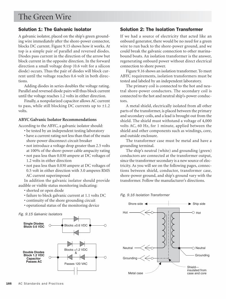
166 AC Standards and Pract ices
Solution 1: The Galvanic Isolator A galvanic isolator, placed on the ship’s green ground-ing wire immediately after the shore-power connector,blocks DC current. Figure 9.15 shows how it works. Attop is a simple pair of parallel and reversed diodes.Diodes pass current in the direction of the arrow butblock current in the opposite direction. In the forwarddirection a small voltage drop (0.6 volt for a silicondiode) occurs. Thus the pair of diodes will block cur-rent until the voltage reaches 0.6 volt in both direc-tions.
Adding diodes in series doubles the voltage rating.Parallel and reversed diode pairs will thus block currentuntil the voltage reaches 1.2 volts in either direction.
Finally, a nonpolarized capacitor allows AC currentto pass, while still blocking DC currents up to ±1.2volts.
ABYC Galvanic Isolator Recommendations
According to the ABYC, a galvanic isolator should:• be tested by an independent testing laboratory• have a current rating not less than that of the main
shore-power disconnect circuit breaker• not introduce a voltage drop greater than 2.5 volts
at 100% of the shore-power cable ampacity rating• not pass less than 0.030 ampere at DC voltages of
1.2 volts in either direction• not pass less than 0.030 ampere at DC voltages of
0.5 volt in either direction with 3.0 amperes RMSAC current superimposed
In addition the galvanic isolator should provideaudible or visible status monitoring indicating:
• shorted or open diode• failure to block galvanic current at 1.1 volts DC• continuity of the shore grounding circuit• operational status of the monitoring device
The Green Wire
Solution 2: The Isolation Transformer If we had a source of electricity that acted like anonboard generator, there would be no need for a greenwire to run back to the shore-power ground, and wecould break the galvanic connection to other marina-bound boats. An isolation transformer is the answer,regenerating onboard power without direct electricalconnection to shore power.
Figure 9.16 shows an isolation transformer. To meetABYC requirements, isolation transformers must betested and labeled by an independent laboratory.
The primary coil is connected to the hot and neu-tral shore-power conductors. The secondary coil isconnected to the hot and neutral ship’s-power conduc-tors.
A metal shield, electrically isolated from all otherparts of the transformer, is placed between the primaryand secondary coils, and a lead is brought out from theshield. The shield must withstand a voltage of 4,000volts AC, 60 Hz, for 1 minute, applied between theshield and other components such as windings, core,and outside enclosure.
The transformer case must be metal and have agrounding terminal.
The ship’s neutral (white) and grounding (green)conductors are connected at the transformer output,since the transformer secondary is a new source of elec-tricity. As you will see on the following pages, connec-tions between shield, conductor, transformer case,shore-power ground, and ship’s ground vary with thetransformer. Follow the manufacturer’s directions.
Hot
Neutral
Grounding
Hot
Neutral
Grounding
Metal case
Shield—insulated from case and core
Shore side Ship side
Fig. 9.16 Isolation Transformer
Blocks ±0.6 VDC
Blocks ±1.2 VDC&
Passes 120 VAC
Double DiodesBlock 1.2 VDC
CapacitorPasses AC
Single DiodesBlock 0.6 VDC
Fig. 9.15 Galvanic Isolators

167Approved Shore-Power Circuits
Figure Volts Phases Galvanic Protection ABYC Reference
9.17 120 1 Galvanic isolator E-11.7.2.2.1
9.18 120 1 Galvanic isolator and generator E-11.7.2.2.1
9.19 120 1 Galvanic isolator and polarity indicator E-11.7.2.2.1
9.20 120/240 1 Galvanic isolator and generator E-11.7.2.2.2
9.21 240 1 Polarization transformer and generator E-11.7.2.3
9.22 120 1 Isolation transformer E-11.7.2.4
9.23 120 1 Isolation transformer E-11.7.2.5
9.24 120 1 Isolation transformer and GFCI E-11.7.2.6
9.25 240 1 Isolation transformer E-11.7.2.7
9.26 240 1 Isolation transformer E-11.7.2.8
9.27 240 1 Isolation transformer and GFCI E-11.7.2.9
9.28 120 1 Polarization transformer and galvanic isolator E-11.7.2.10
9.29 240 1 Isolation transformer E-11.7.2.11
Approved Shore-Power Circuits
The following pages contain a variety of shore-powercircuits, adapted from ABYC Standard E-11. Theyrange from the simplest and most common small-boat,120-volt AC, 30-amp circuit to the heavy-duty 120/240VAC systems found on large power yachts. Each cir-
cuit incorporates galvanic protection in the form ofeither a galvanic isolator or an isolating transformer.For ease in finding the appropriate circuit for yourapplication, here is a guide:

168 AC Standards and Pract ices
Approved Shore-Power Circuits
Shore-power connection
Shore-power cable connector
Shore-power cable
Power inlet (insulated fromboat if isolator installed)
Main shore-powerdisconnect breaker
Galvanic isolator (optional)
Breaker (typical)
120 VACgrounding
To Engine Negativeterminal or its bus
SHORE SIDE
BOAT SIDE
Ungrounded
Grounded
Grounding
Ungrounded
Grounded
Grounding
Fig. 9.17 Single-Phase, 120-Volt System with Shore-Grounded Neutral and Grounding Conductors

169Approved Shore-Power Circuits
120 VACgenerator
Transfer switchGEN–OFF–SHORE
SHORE SIDE
BOAT SIDE
Ungrounded
Grounded
Grounding
Ungrounded
Grounded
Grounding
Breaker (typical)
120 VACgrounding
Main shore-powerdisconnect breaker
Shore-power cable connector
Power inlet (insulated fromboat if isolator installed)
Shore-power connection
Shore-power cable
Galvanic isolator (optional)
To Engine Negativeterminal or its bus
Fig. 9.18 Single-Phase, 120-Volt System with Shore-Grounded Neutral and Grounding Conductors

170 AC Standards and Pract ices
Approved Shore-Power Circuits
Polarity indicator
120 VACdevice
SHORE SIDE
BOAT SIDE
Ungrounded
Grounded
Grounding
Ungrounded
Grounded
Grounding
Breaker (typical) Breaker (typical)
120 VACgrounding
Main shore-powerdisconnect breaker
Shore-power cable connector
Power inlet (insulated fromboat if isolator installed)
Shore-power cable
Shore-power connection
Galvanic isolator (optional)
To Engine Negativeterminal or its bus
Fig. 9.19 Single-Phase, 120-Volt System with Shore-Grounded Neutral and Grounding Conductors

171Approved Shore-Power Circuits
120/240 VAC generator
120 VACgroundingreceptacle
Transfer switchGEN–OFF–SHORE
SHORE SIDE
BOAT SIDE
240 VACdevice
Branchcircuit breaker
120 VACdevice
Branchcircuit breaker
Doublecircuit breaker
Ungrounded
Grounded
Ungrounded
Grounding
Ungrounded
Grounded
Ungrounded
Grounding
To Engine Negativeterminal or its bus
Galvanic isolator (optional)
Main shore-powerdisconnect breaker
Shore-power cable connector
Power inlet (insulated fromboat if isolator installed)
Shore-power connection
Shore-power cable
Fig. 9.20 Single-Phase, 120/240-Volt System with Shore-Grounded Neutral and Grounding Conductors

172 AC Standards and Pract ices
Approved Shore-Power Circuits
120/240 VAC generator
Transformer secondaryovercurrent protection
SHORE SIDE
BOAT SIDE
Encapsulated single-phase1:1 polarization transformerwith metal case
240 VACdevice
120 VACdevice
Ungrounded
Grounded
Ungrounded
Grounding
Ungrounded
Grounded
UngroundedGrounding
Branchcircuit breaker
Doublecircuit breaker
120 VACgroundingreceptacle
Shore-power cable connector
Power inlet (insulated fromboat if isolator installed)
Shore-power connection
Shore-power cable
Main shore-powerdisconnect breaker
Galvanic isolator (optional)
To Engine Negativeterminal or its bus
Transfer switchGEN–OFF–SHORE
Fig. 9.21 Polarization Transformer System with Single-Phase, 240-Volt Input, 120/240-Volt Output, and Generator

173Approved Shore-Power Circuits
Transformer enclosure
Transformer shield
Transformer case ground and shield connection
120 VACgroundingreceptacle
SHORE SIDE
BOAT SIDE
Encapsulated single-phase1:1 isolation transformeriinsulated from boat by aventilated non-conductiveenclosure
120 VACdevice
Ungrounded
Grounded
Grounding
Ungrounded
Grounded
Grounding
To Engine Negativeterminal or its bus
Shore-power cable connector
Power inlet (insulated fromboat if isolator installed)
Shore-power connection
Shore-power cable
Main shore-powerdisconnect breaker
Branchcircuit breaker
Fig. 9.22 Isolation Transformer System with Single-Phase, 120-Volt Input and 120-Volt Output

174 AC Standards and Pract ices
Approved Shore-Power Circuits
Transformer case ground connection
SHORE SIDE
BOAT SIDE
Encapsulated single-phase1:1 isolation transformerwith metal case
Ungrounded
Grounded
Grounding
Ungrounded
Grounded
Grounding
Shore-power cable connector
Power inlet (insulated fromboat if isolator installed)
Shore-power connection
Shore-power cable
Main shore-powerdisconnect breaker
Transformer case
Transformer shield(insulated fromcase and core)
To Engine Negativeterminal or its bus
Branchcircuit breaker
Branchcircuit breaker
120 VACdevice
120 VACgroundingreceptacle
Fig. 9.23 Isolation Transformer System with Single-Phase, 120-Volt Input and 120-Volt Output

175Approved Shore-Power Circuits
Main shore-power disconnect circuit breaker with GFP
Transformer case groundand shield connection
Transformer shield
SHORE SIDE
BOAT SIDE
Encapsulated single-phase1:1 isolation transformerwith metal case
Ungrounded
Grounded
Grounding
Ungrounded
Grounded
Grounding
Shore-power cable connector
Power inlet (insulated fromboat if isolator installed)
Shore-power connection
Shore-power cable
Transformer case
To Engine Negativeterminal or its bus
Branchcircuit breaker
120 VACdevice120 VAC
groundingreceptacle
Branchcircuit breaker
Fig. 9.24 Isolation Transformer System with Single-Phase, 120-Volt Input and 120-Volt Output with Ground Fault Protection
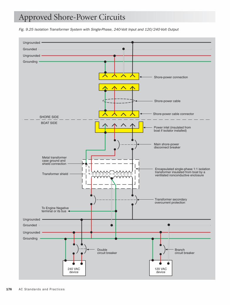
176 AC Standards and Pract ices
Approved Shore-Power Circuits
Transformer shield
Metal transformercase ground andshield connection
Transformer secondaryovercurrent protection
SHORE SIDE
BOAT SIDE
Encapsulated single-phase 1:1 isolationtransformer insulated from boat by aventilated nonconductive enclosure
Ungrounded
Grounded
Ungrounded
Grounding
Ungrounded
Grounded
Ungrounded
Grounding
120 VACdevice
240 VACdevice
Branchcircuit breaker
Doublecircuit breaker
To Engine Negativeterminal or its bus
Shore-power cable connector
Power inlet (insulated fromboat if isolator installed)
Shore-power connection
Shore-power cable
Main shore-powerdisconnect breaker
Fig. 9.25 Isolation Transformer System with Single-Phase, 240-Volt Input and 120/240-Volt Output

177Approved Shore-Power Circuits
Transformer secondaryovercurrent protection
SHORE SIDE
BOAT SIDE
Encapsulated single-phase1:1 isolation transformerwith metal case
Ungrounded
Grounded
Ungrounded
Grounding
Ungrounded
Grounded
Ungrounded
Grounding
120 VACgroundingreceptacle
120 VACdevice
240 VACdevice
Branchcircuit breaker
Doublecircuit breaker
Shore-power cable connector
Power inlet (insulated fromboat if isolator installed)
Shore-power connection
Shore-power cable
Main shore-powerdisconnect breaker
To Engine Negativeterminal or its bus
Transformer case groundand shield connection
Transformer shield
Fig. 9.26 Isolation Transformer System with Single-Phase, 240-Volt Input and 120/240-Volt Output

178 AC Standards and Pract ices
Approved Shore-Power Circuits
Transformer shieldgrounded to case
Transformer secondaryovercurrent protection
SHORE SIDE
BOAT SIDE
Encapsulated single-phase1:1 isolation transformerwith metal case
Ungrounded
Grounded
Ungrounded
Grounding
Ungrounded
Grounded
Ungrounded
Grounding
120 VACdevice
240 VACdevice
120 VACgroundingreceptacle
Branchcircuit breaker
Double circuit breaker
Shore-power cable connector
Power inlet (insulated fromboat if isolator installed)
Shore-power connection
Shore-power cable
Main shore-powerdisconnect breaker
To Engine Negativeterminal or its bus
Fig. 9.27 Isolation Transformer System with Single-Phase, 240-Volt Input and 120/240-Volt Output with Ground Fault Protection

179Approved Shore-Power Circuits
Optional galvanic isolator
Transformer case ground connection
SHORE SIDE
BOAT SIDE
Encapsulated single-phase1:1 polarization transformerwith metal case
Ungrounded
Grounded
Grounding
Ungrounded
Grounded
Grounding
120 VACgroundingreceptacle
120 VACdevice
To Engine Negativeterminal or its bus
Shore-power cable connector
Power inlet (insulated fromboat if isolator installed)
Shore-power connection
Shore-power cable
Main shore-powerdisconnect breaker
Branch circuit breakerBranch circuit breaker
Fig. 9.28 Polarization Transformer System with Single-Phase, 120-Volt Input and 120-Volt Output

180 AC Standards and Pract ices
Approved Shore-Power Circuits
SHORE SIDE
BOAT SIDE
Encapsulated single-phase1:1 isolation transformerwith metal case
Ungrounded
Grounded
Ungrounded
Grounding
Ungrounded
Grounded
Ungrounded
Grounding
Optional galvanic isolator
Branchcircuit breaker
120 VACdevice
240 VACdevice
120 VACgroundingreceptacle
Shore-power cable connector
Power inlet (insulated fromboat if isolator installed)
Shore-power connection
Shore-power cable
Main shore-powerdisconnect breaker
To Engine Negativeterminal or its bus
Transformer secondaryovercurrent protection
Transformer case ground connection
Fig. 9.29 Polarization Transformer System with Single-Phase, 240-Volt Input and 120/240-Volt Output

This page intentionally left blank

Conservation forLiveaboards
182
CHAPTER 10
LED All-Round Light3 Watts
Halogen Mini-Spot5 Watts
Mini Reading Light10 Watts
Thin-Lite Single Short, 8 Watts
PL4-Pin
Compact Replacement12VDC, 13 Watts
Copyright © 1993, 2006 by Charlie Wing. Click here for terms of use.

183
The cost per kilowatt-hour of power generated ona boat is high, whether in dollars or in aggrava-tion. It is easily shown that the dollar cost of a
kilowatt-hour saved is less than that of a kilowatt-hourgenerated, no matter the shipboard source.
This chapter shows you how to reduce your use ofelectricity for lighting, refrigeration, and several otherareas.
The bottom line is that most boaters can cut theironboard power consumption by at least half with littleor no compromise in lifestyle.

184 Conser vat ion for L iveaboards
Before considering solar and wind power, the live-aboard boater should consider the less expensive alter-native form of energy—conservation.
Put yourself to the following test. Your already leakyboat becomes more leaky. Which solution first comesto your mind? If it is to install a second or larger bilgepump, then forget conservation, solar, and wind, andget yourself to a slip where you can tap into shorepower. If fixing the leak seems more logical to you,however, then read on.
If we have learned anything in the past 20 years, itis that, with modest investment and attention to detail,we can save a lot of expensive energy in our homes andoffices. The same is true of boats.
If your boat is typical, this chapter can show youhow to reduce the drain on your batteries by half withvirtually no effect on your lifestyle. By cutting con-sumption in half, you will also reduce the required sizesand costs of the solar and wind systems you may beconsidering adding to your boat. In fact, you mayreduce your consumption to the point where you neverneed run your engine again just to charge your batter-ies!
The old saying “A penny saved is a penny earned”has its analog in energy conservation: “A kilowatt savedis a kilowatt made.” If we can save energy withoutdimishing lifestyle, then it is fair to compare the costof saving a kilowatt-hour to the cost of producing akilowatt-hour in order to see which is the better deal.
Costs of Producing Electricity Figure 10.1 shows the costs per kilowatt-hour of elec-tricity produced by:
• 220-amp alternator on a 20 hp diesel • 110-amp alternator on a 20 hp diesel • 55-amp alternator on a 20 hp diesel • Solar panel at $8 per peak watt • 5-foot wind machine at $1,500 The assumptions used include:
Diesel Power• Used at anchor • Fuel consumption, 0.5 gallon/hour • Fuel price, $2.20/gallon • Price including controls, $7,000 • Life, 10,000 hours • Maintenance, $0.20/hour
Costs per Kilowatt-Hour
Solar Power:• Used all year • Size, 50 watts peak output • Price including controls, $400 • Life, 10 years• Average daily sunshine, 5.2 hours • Annual maintenance, $0
Wind Power:• Used all year • Size (blade diameter), 5 feet • Price including controls, $1,500 • Life, 10 years • Average wind speed, 10 knots • Annual maintenance, $100 Assuming the alternators cycle the battery between
the charge states of 50% and 90%, the relative produc-tion costs per kilowatt-hour shown in Figure 10.1 ofelectricity are:
• 220-amp alternator, $1.25• 110-amp alternator, $2.30 • 55-amp alternator, $4.10• Solar panel, $0.42 • 5-foot wind machine, $0.59
The Costs of Conserving Electricity Now let’s compare the costs per kilowatt-hour of elec-tricity saved by two simple changes: switching fromincandescent to fluorescent lighting, and halving thelosses of a DC-powered refrigerator.
Lighting Conversion
An 8-watt fluorescent fixture puts out nearly as muchlight as a 40-watt incandescent lamp. Assume eachreplacement fluorescent fixture costs $30. Fluorescentbulbs cost four times as much as incandescent bulbs,but they last proportionally longer, so the cost of bulbreplacement is the same.
Assuming a 10-year fixture life, and that the lampis operated an average of 2 hours per day throughoutthe year, the lifetime savings of the fluorescent replace-ment fixture is 124 kilowatt-hours. The cost per kilo-watt-hour saved is $30/124 = $0.24—half the cost ofelectricity produced by the cheapest alternative means,and one-tenth the cost of the 110-amp alternatorpower.

185Costs per Ki lowatt -Hour
Refrigerator Losses
Assume that our 8-cubic-foot refrigerator with 2-inchfoam insulation draws 5.5 amps at 12 volts DC and hasa 40% duty cycle. Its daily consumption would be: 5.5amps × 24 hours × 0.40 = 52.8 Ah, or 0.63 kilowatt-hour.
If we were to double the insulation of the refrigera-tor walls to 4 inches, install a better door gasket andinstall a trap in the drain, we would probably reducethe refrigerator’s total heat loss by half, or 0.315 kilo-watt-hour/day. Over 10 years of continuous use, thesavings would amount to 1,186 kilowatt-hours.
The most effective way to double the refrigeratorinsulation would be to line the inside of the box with 2-inch polyurethane foam board and then glass over thefoam. If accessible, cavities between the box and thehull and cabinetry can be filled with expanding foam.
The first method has the advantage of simplicity,but reduces the volume of the box. The second methodretains the box dimensions, but its effectiveness isuncertain without disassembly of the cabinetry.
Method one could be accomplished for about $50in materials and $200 in labor by a reasonably compe-tent fiberglass technician. Cost per kilowatt-hour savedis thus $250/1,186 kilowatt-hours = $0.21/kilowatt-hour.
Both of our retrofits are at least twice as cost effec-tive as adding solar and wind power, and ten timescheaper than generation by shipboard diesel.
Caveat: The above calculations assume year-rounduse of the boat for 10 years. If you use your boat only10% of the year, then solar and wind costs per kilowatt-hour should be multiplied by a factor of 10. That is whythis chapter is titled Conservation for Liveaboards.
Cos
tofE
lect
ricity
, $/k
Wh
Depth of Battery Discharge, %
0 20 40 60 80 1000.00
1.00
2.00
3.00
4.00
220-amp alternator
Charging two 8D batteries(440 Ah) to 85% using:
0.50
1.50
2.50
3.50
Wind
10 30 50 70 90
Solar
Utility
110-amp alternator
55-amp alternator
ENGINE COSTS:
Fig. 10.1 Costs per Kilowatt-Hour of Generated Power (based on 10 years of daily consumption)

186 Conser vat ion for L iveaboards
Most boats come from the factory equipped withincandescent lighting. Both the bulbs and the fixturesare inexpensive, but it is a false economy for the owner.You can reduce your lighting load by a full two-thirdsthrough three simple retrofits (see Figures 10.3 and10.4): fluorescent galley and head fixtures, halogenreading-light fixtures, and, for those who anchor out alot, a light-actuated anchor light switch or a 3-wattLED all-around light.
Fluorescent Fixtures
The galley requires bright lighting, but 8-watt fluo-rescent slim-line fixtures cast as much light as common40-watt incandescent fixtures. For serious chefs, largerfluorescents rated at 13 watts (65 W), 16 watts (80 W)and 26 watts (130 W) are available. The head is anothergood location for the same types of fluorescent lighting.
If you have 120 VAC light fixtures aboard, you canconvert them with compact fluorescent screw-inreplacement bulbs and then run these fixtures from aDC-to-AC inverter for similar savings.
If the fluorescent fixtures affect any of your elec-tronics, install the filters described in Chapter 13.
Halogen Spot Fixtures
Many of the lights below deck are for reading. Themost common small incandescent fixtures spread thelight from 15-watt bulbs over an area ten times that ofa page. These lamps can be directly replaced with 5- or10-watt halogen spot-task lamps, which achieve thesame light intensity by concentrating the beam from ahigh-efficiency halogen bulb onto a page or task.
You can save further lighting energy by installingthe solid-state dimmer circuit described in Chapter 14.You can then dim the lights for a warmer ambience,save electricity, and double the lifetime of the lamps, allat the same time.
LEDs
The future of marine lighting is all about LEDs. WhileFigure 10.2 shows the present efficacy range of LEDsas 22 to 42 lumens per watt (about twice that of incan-descents and half that of fluorescents), there is littledoubt that 60 to 100 lumens per watt will ultimatelybe achieved.
The same efficiency as fluorescents, 10 to 100 timesthe life of halogens and incandescents, indestructiblepackaging, and easily and efficiently dimmed: soundslike a no-brainer.
Lighting Savings
Anchor Lights
International navigation law requires boats less than 20meters long to display an anchor light that is visiblefor at least 2 nautical miles. The required luminance isequivalent to that produced by a 10-watt incandescentlamp.
The battery-powered “marker lights” many boatersemploy do not meet the 2-mile requirement. Simplyreducing incandescent lamp wattage puts your boat injeopardy—at least from the standpoint of liability.
Two legal, energy-saving alternatives are:
1. Using an automatic anchor light switch2. Switching to an LED all-round light
Anchor light switch. To run the light from sunrise towhen you wake up (or when you first remember thelight is on, which may be considerably longer) is waste-ful, however. The automatic anchor light switch inChapter 14 turns the anchor light on and off preciselyat sunset and sunrise, saving about 2 Ah per day. If youleave your boat unattended it will save an average ofabout 10 Ah per day. If building the circuit yourselfisn’t your idea of a fun way to spend a weekend, sev-eral commercial versions are also available.
LED all-around light. Perko (no doubt others will fol-low suit) has developed an LED all-round light that sat-isfies the 2 nm visibility requirement for vessels under20 meters. The design takes advantage of both theLED’s inherent efficiency (two times that of incandes-cents) and its narrow beam (±5°) to focus the light atthe horizon. The result is a 75% power reduction, from10 to 12 watts to only 3 watts.
Red
Incandescent Halogen Fluorescent LED
Ora
nge
Gre
enW
hite
Effi
cacy
, Lum
ens
per
Wat
t
0
10
20
30
40
50
60
70
80
90
100
Fig. 10.2 Efficacy of Light Sources

187Light ing Savings
PL2-Pin
PL4-Pin
T-5 min. bipin
T-8 med. bipin
Compact Replacement12VDC, 13 Watts
Cluster BayonetReplacement
Festoon
G4 G9
BayonetDouble-Contact
BayonetSingle-Contact
SphericalMed. Screw-Base
Single
FLUORESCENTS
INCANDESCENTS
HALOGENSLEDS
Perko LEDAll-Round Light
3 Watts
Aqua-SignalHalogen Mini-Spot
5 Watts
West MarineMini Reading Light
10 Watts
Thin-Lite Single Short, 8 Watts
Thin-Lite Dual Short, 16 Watts
Thin-Lite Single Long, 13 Watts
Thin-Lite Dual Long, 26 Watts
Fig. 10.3 Bulbs for Boats
Fig. 10.4 A Collection of Efficient Fixtures

188 Conser vat ion for L iveaboards
How Refrigeration WorksIf you know that water boils (turns from a liquid to agas) at 212°F at normal atmospheric pressure, but thatits boiling temperature rises at higher pressure (suchas in a pressure cooker), and that evaporating waterabsorbs a lot of heat (think of getting out of the wateron a windy day), then you are well on your way tounderstanding how refrigerators, air conditioners, andheat pumps work.
Unfortunately, the boiling point of water is too highto use it as a refrigerant, but other fluids exist that boilat below the freezing point of water! One such refrig-erant is ES-12a (see Figure 10.5), one of many refrig-erants developed to replace R-12 (Freon), now banneddue to its adverse effect on the earth’s ozone layer.
As shown in Figure 10.5, at atmospheric pressure(15 psi), ES-12a boils at about –26°F. If we compress itto a pressure of 150 psi, its boiling temperature rises toabout 110°F. Since this rise approximates the rangefrom freezer temperature to maximum atmospherictemperature, ES-12a may prove useful.
In the refrigeration system in Figure 10.6, the refrig-erant is sucked into a compressor. The compressorworks like the piston of an internal combustion engine,except power is applied to the piston by the crankshaftinstead of the other way around. The piston com-presses the gas to about 150 psi, in the process raisingits temperature to about 120°F.
The hot, compressed gas then flows through thedischarge line to a condenser—a heat exchanger—where it is cooled to below its condensation point andchanges back to a liquid. In order to condense the120°F gas, the condenser must be located in a coolspace or be cooled by seawater.
From the condenser the hot liquid first passesthrough a drier, which assures no water contaminatesthe refrigerant, then on to an expansion valve.
The function of the expansion valve is to control therelease of the hot liquid into the low pressure of theevaporator coil. When the fluid emerges from theexpansion valve, the dramatic drop back to near atmo-spheric pressure causes it to boil (evaporate) at about–25°F, absorbing heat from the evaporator coil. Theevaporator coil is the frost-covered tubing you see in anolder refrigerator or freezer.
From the evaporator the now-cool gas is againsucked into the compressor, and the cycle is repeated.
Now for some details:
Refrigeration Savings
Condenser
Efficient condenser operation requires efficient heatremoval from the tubing. Air-cooled condensers uti-lize metal fins on the tubing and air flow over the fins toremove the heat. The efficiency of such an arrangementdepends on both the temperature of the air and the rateof airflow. A stuffy engine compartment is obviouslynot a good location for the condenser.
Evaporator
The evaporator shown has little heat-storage capacity.As a result the compressor will cycle on and off everyfew minutes. A lot of energy is lost starting the com-pressor, so the efficiency is relatively low. A better sys-tem encloses the evaporator coil in a holding plate filledwith a liquid having a low freezing point. The compres-sor runs until all of the holding-plate liquid freezes.The holding plate then functions like a block of ice.Properly sized for the refrigerator box, a holding-platesystem requires running the compressor just once a dayfor an hour or so. By running such a system only whenthe engine is running, all of the considerable load isremoved from the boat’s batteries.
Controls
A small temperature-sensing bulb on a capillary tube isattached to the suction end of the evaporator coil. Thetemperature-dependent pressure in the tube controlsthe rate of fluid flow through the valve, and thus thetemperature of the evaporator coil. When the tempera-ture of the refrigerator box rises, a thermostat switchesthe compressor on to move and compress refrigerant,cooling the box.
0-40
-20
0
20
40
60
80
100
120
140
30 60 90 120 150 180
GAS
Pressure, psi
Tem
pera
ture
, °F
Evaporation
LIQUID
Condensation
Fig. 10.5 Pressure-Temperature Curve for ES-12a Refrigerant

189Refr igerat ion Savings
Expansionvalve
CompressorSuction line Discharge line
Low-pressure liquid
Insulation
THE BOX
High-pressure liquid (hot)
High-pressure gas
Low-pressure gas (cold)
Dryer
Evaporator
Condenser
Fig. 10.6 How Refrigerators Work

190 Conser vat ion for L iveaboards
Calculating the Cooling Load First, two definitions:
• Btu = heat that changes the temperature of 1pound of water by 1F°.
• Heat of fusion of water (heat absorbed by 1 poundof ice when it melts) = 144 Btu.
Next, Figure 10.7 shows the basic equation of con-ductive heat loss:
H = A × ∆T/R
where:H = heat loss through A, in Btu/hour A = area of surface in square feet
∆T = temperature difference, Toutside – TinsideF°R = thermal resistance
To this conductive heat loss through the refrigeratorwalls we have to add the losses of infiltration (air leak-age through the lid and drain) and cooldown (heat thatmust be removed from warm objects added to thebox).
The Refrigerator Box Figure 10.8 shows the dimensions of a typical 8-cubic-foot refrigerator. The walls are constructed of 2-inchurethane foam, lined with fiberglass. Plugging thenumbers into the heat-loss equation above:
A = 28 square feet (insulation mid-plane)∆T = 75°F outside – 40°F inside
= 35F°R = 2 inches × R-6/inch
= 12 H = 28 × 35/12
= 82 Btu/hour
If this box had a perfect lid and we never opened it,it would melt 82 Btu/hour/144 Btu/pound = 0.57pound of ice per hour or 13.7 pounds of ice per day. Ifwe add another third (27 Btu/hour) to the heat loss forinfiltration and cooldown, our totals become 109Btu/hour and 18 pounds of ice per day.
How much electricity will it take to replace the ice?The answer is—it all depends. It depends primarily onthe efficiency of the refrigeration system, the refrigera-tor’s coefficient of performance (COP), defined as:
COP = watts removed/watts used
We’ll also need a conversion factor:
Ah/day = 0.586 × Btu/hour
Refrigeration Savings
AH H
R
Tinside Toutside
∆T
Fig. 10.7 Conductive Heat Loss
28"
28"
Before Retrofit
After Retrofit
28"
28"
28"
28"
24"
24"
24"
20"
20"
20"
Fig. 10.8 Typical Refrigerator Box

191Refr igerat ion Savings
COP depends on how hard the compressor has towork pumping heat from the evaporator (cold) side tothe condenser (hot) side. When the temperatures ofevaporator and condenser are the same, the compres-sor can remove about 3 Btu of heat energy, using theequivalent of 1 Btu of electrical energy, yielding a COPof 3.0.
At the opposite extreme, the typical refrigerator iscapable of moving heat across a maximum differenceof about 150F°, at which point its COP becomes zero.
Figure 10.9 shows the relationship between COPand condenser temperature for a typical small refrig-erator, assuming the evaporator is at 20°F.
The temperature of the condenser depends on itstype and location. Table 10.1 shows typical condenseroperating temperatures and resulting COPs for differ-ent condenser types and locations in the boat.
Assume the condenser is located in free air at 75°Fbut has no fan. According to Table 10.1, its COP willbe about 1.3. Our example refrigerator will then draw190 Btu/hr × 0.586/1.3 = 49 Ah/day.
A Typical Refrigerator Retrofit To reduce the refrigeration load we can take three steps:
1. Increase wall insulation.2. Decrease infiltration with a better lid gasket and
a drain trap.3. Increase condenser COP with a fan.
Wall Insulation
At the cost of 3.4 cubic feet of interior space, we candouble the insulation of all surfaces and increase theirR-values to R-24. Because we also have decreased theheat loss area (measured at the midpoint of the insula-tion) to 24 square feet, conductive heat loss is decreasedby 47 Btu/hour to 35 Btu/hour.
Infiltration
By installing a better gasket on the lid and a better melt-water drain trap, we might decrease the losses due to airleaks by half, or 13 Btu/hour, and the total heat loss by60 Btu/hour to 49 Btu/hour.
Condensor COP
By installing a thermostatically controlled 12-volt DCfan to move air through the condenser coils, we canincrease the condenser COP from about 1.3 to 1.7 atthe cost of about 2 Ah per day to power the fan. Most
marine and RV refrigeration manufacturers offer suchfans as an option. If not, small fans that run on 12 VDCare readily available at electronics stores, such asRadioShack. DIY Project 13 (Chapter 14) is a circuitto control such a fan.
Manufacturers also sometimes offer water cooling,where the condenser is cooled by water circulated to aheat exchanger mounted on the bottom of the hull.While more efficient in cooler waters, such systems aresusceptible to becoming fouled with growth.
Net Refrigerator Savings
With the above improvements, our new refrigerationload becomes 60 Btu/hour × 0.586/1.7 = 20.7 Ah/day—a decrease of more than 50%.
4020 60 80 100 120 140 160
1
0
2
3
Condenser Temperature, °F
Coe
ffici
ento
fPer
form
ance
(CO
P)
Fig. 10.9 Refrigerator COP vs. Temperature
Table 10.1 Refrigerator COP vs. Location
CondenserCondenser/Location Temp., °F COP
Air-cooled in 110°F engine 140 0.6 compartment, no fan
Air-cooled in 110°F engine 120 1.0compartment with fan
Air-cooled in 75°F free air with no fan 105 1.3
Air-cooled in 75°F free air with fan 85 1.7
Water-cooled, intake water 75°F 85 1.7
Water-cooled, intake water 60°F 70 2.0

192 Conser vat ion for L iveaboards
Cabin Fans
The most efficient way to cool a hot cabin is with awind chute attached to a hatch, but its use assumes abreeze and that the boat is free to swing into it.
On hot, still nights, small fans directed at your bodycan make the difference between sleeping and not. Thetypical 6-inch cabin fan draws about 1 amp, but themost efficient fans draw only 0.3 amp. In 8 hours theaccumulated difference is more than 5 Ah per fan.
Electronics
The power consumption of a sound system dependsmore on the efficiency of the speakers than that of theelectronics. Therefore, look for speakers designed tobe driven by computers, as they are the most efficient.
No one is willing to watch black and white televi-sion any longer, so the choice is between the older stan-dard cathode-ray (CRT) color television and the newer,solid-state LCD versions. Wattage is roughly propor-
Other Savings
tional to the area of the screen (diameter squared).From a 19-inch CRT to a 6-inch LCD there is a 65-watt,or 5-amp, difference. If you are an average 4-hour-per-day boob-tube watcher, the daily difference is greaterthan the drain of the anchor light. An excellent way tosave energy is, therefore, to install a 6-inch LCD televi-sion and sit closer!
VCRs and DVD players are becoming very popularon boats. In fact, trading videotapes and DVDs isnearly as common as trading paperback books. Thetypical 120-volt AC record/play VCR/DVD machinedraws about 17 watts. Portable 12-volt DC play-onlymodels draw 10 watts.
The Bottom Line Table 10.2 shows, as promised, how the daily powerconsumption of a typical cruising boat can be reducedby half with no significant degradation of lifestyle.
Table 10.2 Power Consumption of a Typical versus an Energy-Efficient Liveaboard Boat
Hours/ Typical Efficient Area Device Watts Amps Day Ah Ah
Galley Microwave 550 45.8 0.15 6.9 6.9 Toaster 800 66.7 0.04
Blender 175 14.6 0.01 0.1 0.1
Coffee grinder 160 13.3 0.01
Refrigerator 2" insul. 60 5.0 10.00 49.0
4" insul 60 5.0 5.00 20.7
Head Hair dryer 1,200 100.0 0.03
Lights Reading 2 incand., 15 W 30 2.5 2.00 5.0
2 halogen, 5 W 10 0.8 2.00 1.6
Galley 2 incand., 25 W 50 4.2 2.00 8.4
2 fluor., 8 W 16 1.4 2.00 2.8
Anchor manual, 10 W 10 0.8 14.00 11.2
auto., 10 W 10 0.8 11.00 8.8
Fans Typical 6-inch, 100 cfm 12 1.0 5.00 5.0
Most efficient, 100 cfm 4 0.3 5.00 1.5
Electronics Stereo 20 W/channel 60 5.0 1.00 5.0
7 W/channel 35 3.0 1.00 3.0
Television, color, 19" CRT 80 6.7 2.00 13.4
15" LCD 36 3.0 2.00
6" LCD 15 1.25 2.00 2.5
VCR or DVD Typical 120-volt AC 17 1.4 1.0 1.4
12-volt DC play-only 10 0.8 1.0 0.8
Totals 105.4 48.7

This page intentionally left blank

Solar Power
194
CHAPTER 11
A
B
C
DE
Copyright © 1993, 2006 by Charlie Wing. Click here for terms of use.

195
Is solar for you? Would the power produced by solarpanels pay back their cost?
There is quite a collection of commercially availablephotovoltaic panels. Interpreting specificationsrequires that we first understand how photovoltaicpanels work. We also need to consider panel orienta-tion in estimating daily output.
Once the decision has been made, mechanical instal-lation is quite simple. Electrical installation integratesthe panels into the existing 12-volt DC alternator/battery system.
Following the rules for solar success virtually guar-antees your solar satisfaction.

196 Solar Power
A solar, or photovoltaic, installation is a one-timeinvestment with a fuel- and maintenance-free lifetimeof 10 years or longer. Whether a photovoltaic systemwould prove cost effective on your boat, however,depends very much on how you use the boat. If you liveaboard and are away from the dock at least half of thetime, the answer is a definite “yes.” If you cruise 1month each summer, the answer is probably “no.”
Figure 11.1 shows the percentage of daily electricalload supplied by photovoltaic panels among 71 live-aboard cruisers surveyed in Florida and the Bahamas.The average installation was far smaller than optimal,yet the average percentage of power supplied was a sig-nificant 40%. Had the array sizes been optimal, I amsure the power supplied would have been in the 80 to100% range.
Also note from Figure 11.1 that cruisers who hadboth solar and wind systems garnered more than 90%of their power from the combination. Those havingwind power, but no solar, generated 60% from thewind.
Figure 10.1 compared the costs per kilowatt-hour ofelectricity produced by photovoltaic panels, windmachines, and engine-driven alternators. The photo-voltaic cost of $0.42/kilowatt-hour assumed:
• System used year-round • Panel size—50 watts peak output • Price including controls—$400 • Life—10 years• Average daily sunshine—5.2 hours • Maintenance—$0 Such a panel would produce on average 5.2 hours
× 50 watts = 0.26 kWh per day, or 95 kWh per year. Analternative source of power would be a high-output,110-amp alternator, charging batteries on a 50 to 85percent-of-charge cycle. This, according to Figure 10.1,would produce power at a cost of $2.30 per kilowatt-hour.
Compared to the cost of alternator power, solar sav-ings would be $2.30 – $0.42 = $1.88 per kilowatt-hour.At 95 kilowatt-hours per year, annual savings wouldbe $179, and the photovoltaic system would pay foritself in $400/$177 = 2.2 years. That amounts to receiv-ing a tax-free return on investment of 45%. Try tomatch that at your local bank!
On the other hand, if the boat were used but 1month out of the year, the payback would be 27 years—longer than the projected life of the system.
Is Solar for You?
0
20
40
60
80
100
Wind & Solar
SolarOnly
None
Per
cent
of L
oad
Gen
erat
ed
Fig. 11.1 Solar Energy Production among 71 Cruisers

197How Photovoltaics Work
Figure 11.2 shows how a photovoltaic panel works.Solar energy in the form of photons penetrates thephotovoltaic material. Each photon transfers enoughenergy to the photovoltaic atoms to release an electron.If we connect the grid on the sunlit side to the conduct-ing base on the backside, the free electrons will flowthrough the external conductor and load to rejoinatoms having missing electrons.
Each free electron has a potential of about 0.6 volt.A panel typically consists of from 30 to 36 cells, con-nected in series to produce an open-circuit voltage offrom 18 to 22 VDC. The theoretical maximum effi-ciency of this conversion of light energy to electricalenergy is about 28%. As we will see, however, the effi-ciencies achieved in manufacture are improving butstill fall far short of theory.
Photovoltaic collector materials take three commonforms: monocrystalline silicon, polycrystalline silicon,and amorphous silicon. Crystalline silicon is grown inthe form of large crystals, which are sawn into thinwafers to form the cells.
Monocrystalline cells consist of single, large crystalsgrown and drawn from melted silicon in the form oflarge rods. Due to their crystalline perfection, they havethe highest efficiencies, ranging from 14 to 17%.
Polycrystalline silicon is formed by pouring meltedsilicon into blocks, the molten silicon forming manysmall crystals on cooling. These polycrystalline blocksare then sawn into cells. Because of defects betweenthe crystals, the conversion efficiency of polycrystallinesilicon ranges between 13 and 15%.
Amorphous silicon is produced by the less expen-sive process of depositing vaporized silicon onto ametal substrate. In addition to being less expensive toproduce, amorphous silicon can be fabricated intosemirigid and flexible panels. Semi-rigid panelsattached to a thin steel backing can be adhered to adeck and stepped on without damage. Flexible panelswith a heavy fabric backing can be attached to boatcanvas. Unfortunately, the efficiency of amorphous sil-icon is only 5 to 7%, so twice as much collector area isrequired as for crystalline panels.
Most crystalline photovoltaic panels are warrantedfor 20 years, but there is no reason, barring physicaldamage, that they would not last 30 years or longer.
Amorphous silicon panels, because they are notenclosed in a rigid, protective frame, are generally war-ranted for only 5 years.
How Photovoltaics Work
Tempered glass
Conductinggrid
N-semiconductor
PN junction
P-semiconductor
Conducting layer
Fig. 11.2 How Photovoltaics Work

198 Solar Power
Table 11.1 lists the specifications of the most popularphotovoltaic panels. All panel output ratings are for25°C (86°F). Rigid panels are in aluminum frames, andcan be mounted to davits, bimini frames, and stan-chions. Semirigid panels may be adhered directly to the
Photovoltaic Panels
deck. Flexible panels may be draped anywhere. Onaverage you can expect (in 2005) to pay about $6 perrated watt for rigid panels, $8 for semirigid, and $12 forflexible. Add about $2 per rated watt for controls andmounting hardware.
Table 11.1 Photovoltaic Panel Specifications1
Rigid (R) Open- Short-Semirigid (S) Dimensions, Rated Rated Circuit Circuit Warranty
Model Flexible (F)2 inches Watts Amps Volts Amps Years
ICP Solar Pro3
Plug’n’Play 30 R 41 x 12.4 30 2.00 — — Life Plug’n’Play 50 R 41.3 x 20 50 3.30 — — Life Plug’n’Play 75 R 50 x 23.3 75 5.00 — — Life Plug’n’Play 100 R 60.3 x 28 100 6.70 — — Life
Solara
SM40M S 16.6 x 10.7 10 0.50 21.0 — 20 SM60M S 24.4 x 9.8 15 0.90 21.0 — 20 SM80M S 16.9 x 17.7 20 1.10 21.0 — 20SM120M S 23.2 x 17.7 30 1.70 21.0 — 20SM160M S 29.0 x 17.7 40 2.20 21.0 — 20SM225M S 29.5 x 24.0 56 3.00 21.0 — 20
United Solar (Unisolar)
USF-5 F 21.3 x 9.7 5 0.30 16.5 0.33 5 USF-11 F 21.3 x 16.7 11 0.62 16.5 0.69 5 USF-32 F 55.8 x 16.7 32 1.94 16.5 2.10 5
Kyocera
KC35 R 18.5 x 25.7 35 2.33 18.8 2.50 25KC40 R 20.7 x 25.7 40 2.34 21.5 2.48 25 KC50 R 25.2 x 25.7 50 3.00 21.5 3.10 25 KC60 R 29.6 x 25.7 60 3.55 21.5 3.73 25 KC70 R 34.1 x 25.7 70 4.14 21.5 4.35 25 KC80 R 38.4 x 25.7 80 4.73 21.5 4.97 25 KC120-1 R 56.1 x 25.7 120 7.10 21.5 7.45 25
Shell Solar (Siemens)
SM20 R 22.3 x 12.9 20 1.38 18.0 1.60 10SM46 R 42.7 x 13 46 3.15 18.0 3.35 25 SM55 R 50.9 x 13 55 3.15 21.7 3.45 25 SM75 R 47.3 x 20.8 75 4.40 21.7 4.80 25 SM110 R 51.8 x 26 110 6.30 21.7 6.90 25
BP Solar (Solarex)
BP MSX5L S 10.8 x 10.5 4.5 0.27 20.5 0.30 5BP MSX10L S 17.5 x 10.5 10 0.58 21.0 0.65 5 BP MSX20L S 17.5 x 19.5 20 1.17 21.0 1.29 5 BP MSX30L S 24.3 x 19.5 30 1.75 21.0 1.94 5 BP MSX40 R 29.9 x 19.7 40 2.37 21.0 2.58 20 BP MSX60 R 43.5 x 19.7 60 3.56 21.0 3.80 25 1 All ratings at 25°C (86°F). 2 Flexible panels for mounting directly to deck. 3 Plug’n’Play panels include a charge controller.

199Interpret ing Specificat ions
Figure 11.3 shows the voltage-current curve for a typi-cal 30-cell photovoltaic panel in full sunlight. With out-put terminals shorted, the panel put out its short-circuit current (here 3.3 amps). With output terminalsnot connected, current is zero, but output voltage is theopen-circuit voltage (here 18.0 volts). Maximum poweroutput is achieved at the knee of the curve where therated current (3.0 amps) times the rated voltage (14.7volts) equals the panel’s rated power (44 watts).
Figure 11.4 shows how the voltage-current curvesvary both with number of cells and with panel tem-perature. Panel specifications are given for a panel (notair) temperature of 25°C (86°F). Both voltage and cur-rent decrease at higher temperatures. For this reason,panels should be mounted with free airflow beneathto minimize operating temperature. Panels in the trop-ics should have higher voltage ratings as well.
The effect of shading is not shown in manufactur-ers’ voltage-current curves. Shading the panel fromdirect sun does not affect open-circuit voltage, butreduces power output under load roughly in propor-tion to the percentage of shaded area.
Finally, unless built in, you should install a Schottkyblocking diode to prevent reverse-current flow fromthe batteries at night. Better yet, install a regulator thatopens the circuit whenever the panel voltage is less thanthat of the battery.
A common mistake in selecting solar panels is fail-ing to account for all of the voltage drops. Select a panelwhose rated voltage at your expected operating tem-perature is at least 14.8 volts, since 14.8 volts – 0.4 volt(blocking diode drop) = 14.4 volts, the voltage requiredfor fully charging lead-acid batteries. In order to equal-ize the batteries, the blocking diode can be temporar-ily shorted with clip leads, raising the voltage to 14.8.
Interpreting Specifications
3.0
2.0
1.0
4.0
0
Output Volts50 10 15 20 25
30 Cell Panel
Output @ 68°F
@ 86°F
@ 104°F
@ 122°F
Out
putC
urre
nt,A
mps
Output Volts50 10 15 20 25
3.0
2.0
1.0
4.0
0
33 Cell Panel
Output @ 68°F
@ 86°F
@ 104°F
@ 122°F
Out
putC
urre
nt,A
mps
Output Volts50 10 15 20 25
Out
putC
urre
nt,A
mps 3.0
2.0
1.0
4.0
0
36 Cell Panel
Output @ 68°F
@ 86°F
@ 104°F
@ 122°F
Fig. 11.4 Typical Photovoltaic Output vs. Number of Cellsand Panel Temperature
Output Volts50 10 15 20 25
Out
put C
urre
nt, A
mps 3.0
2.0
1.0
4.0
0
Short circuit amps
Open-circuitvolts
Ratedpowerpoint
14.7
V
3.0 A
Fig. 11.3 Typical Photovoltaic Panel Output Curve

200 Solar Power
To understand how panel orientation affects the outputof a photovoltaic system, we must consider how the sunmoves through the sky, both throughout the day andwith the seasons.
Figure 11.5 shows the track of the sun over a boatlocated at latitude 24°N (southern Florida) at the springand fall equinoxes (March 21 and September 21), andthe summer and winter solstices (June 21 and Decem-ber 21). On June 21, the sun reaches its highest noonelevation, 90°. On December 21, the sun reaches itslowest noon elevation, 43°. Further, the sun is above thehorizon approximately 16 hours in June but only 8hours in December. We would, therefore, expect a lotless solar input in December than in June.
Panel output ratings assume full sunlight with thesun’s rays normal (perpendicular) to the panel surface.Panels in large utility “solar farms” are mounted onframes that continuously track the sun’s orbit for max-imum output.
What can we do about orientation on a boat? You’reobviously not going to install a tracking mechanism,and most people would get tired of adjusting panel ori-entation three or four times a day. So the question is:what fixed tilt is best?
Figure 11.6 compares the solar radiation on a hori-zontal surface (tilt = 0°) and surfaces tilted to the southat the latitude angle, for latitudes 24°N (Miami) and40°N (New York), on both the longest (June 21) and
Panel Orientation
shortest (December 21) days. On June 21, if we areboth smart and mobile, we will be at, or around, lati-tude 40°N. Figure 11.6 shows that a horizontal panelwill collect 119% of the radiation collected by a fixedpanel tilted south at 40°.
On December 21 we hope to be in the neighbor-hood of Miami, where our horizontal panel will col-lect 72% as much radiation as a fixed panel tilted southat 24°.
Thus we see, averaged over the year, a horizontalpanel will perform as well as a fixed, south-tilted panel.
“But,” you say, “if I were at a dock, I could tilt mypanels toward the noon sun.” But if you were at a dock,you wouldn’t need photovoltaic panels.
Further, if you were on a mooring or anchor, yourboat would swing without regard for the position ofthe sun. Any fixed orientation you selected might beperfectly right at one moment but perfectly wrong anhour later. There is only one orientation that doesn’tchange as a boat swings: horizontal (facing straight up).
To show the effect of compass direction, Figure 11.7compares the solar radiation on horizontal panels andvertical panels facing north, east, south, and west.Although vertical east and west panels collect signifi-cant amounts of radiation in morning and afternoonrespectively, both collect for only half a day, so theirtotal collection is small. Conclusion: the only practicalsolar panel orientation on a cruising boat is horizontal.
E
W
SN
June
MarSep
DecNoon
altitude90°
Noonaltitude67°
Noon
altitude
43°
Fig. 11.5 Track of the Sun Through theDay and the Seasons

201Panel Or ientat ion
0Horizontal (total 2574)24° Tilt (total 2230)
24°N
6 7 8 9 10 11 12 1 2 3 4 5 6AM PM
100
200
300
00
Horizontal (total 2648)40° Tilt (total 2224)
Hour of Day6 7 8 9 10 11 12 1 2 3 4 5 6
AM PMHour of Day
6 7 8 9 10 11 12 1 2 3 4 5 6AM PMHour of Day
6 7 8 9 10 11 12 1 2 3 4 5 6AM PMHour of Day
40°N
24°N
40°N
JUNE 21 DEC 21
Horizontal (782)
40° Tilt (1634)
Horizontal (1474)
24° Tilt (2058)
Inso
latio
n,B
tu/s
q.ft.
/hr.
100
200
300
Inso
latio
n,B
tu/s
q.ft.
/hr.
100
200
300
00
Inso
latio
n,B
tu/s
q.ft.
/hr.
100
200
300
Inso
latio
n,B
tu/s
q.ft.
/hr.
Fig. 11.6 Hourly Radiation on Horizontal and Tilted Surfaces
East vert.
So. vert.
Horizontal
Northvertical
0
24°N
6 7 8 9 10 11 12 1 2 3 4 5 6AM PM
100
200
300
00
Hour of Day6 7 8 9 10 11 12 1 2 3 4 5 6
AM PMHour of Day
6 7 8 9 10 11 12 1 2 3 4 5 6AM PMHour of Day
6 7 8 9 10 11 12 1 2 3 4 5 6AM PMHour of Day
40°N
24°N
40°N
JUNE 21 DEC 21
Inso
latio
n,B
tu/s
q.ft.
/hr.
100
200
300
Inso
latio
n,B
tu/s
q.ft.
/hr.
100
200
300
00
Inso
latio
n,B
tu/s
q.ft.
/hr.
100
200
300
Inso
latio
n,B
tu/s
q.ft.
/hr.
Horizontal
East vert.So. vert.
So. vert.West vert.
West vert.
Horizontal
Horizontal
No. vert.
No. vert.
No. vert.
So. vert.
West vert.East vert.
West vert.
East vert.
Fig. 11.7 Hourly Radiation on Horizontal and Vertical Surfaces

202 Solar Power
Because the fixed horizontal orientation is the mostpractical on a non-stationary platform, solar-availabil-ity tables and maps often show total radiation on a hor-izontal surface. Figure 11.8 contains such seasonalmaps. Table 11.2 lists, for selected locations, more pre-cise values of average daily solar radiation falling onhorizontal surfaces during:
• the sunniest month (Highest Month)• the least sunny month (Lowest Month)• the entire year (Annual Average)The values are in equivalent hours of full sunlight,
where full sunlight is defined as 1,000 watts/meter2.These values allow easy estimation of solar panel
performance: the average daily output is simply thepanel rating in watts times the equivalent hours of fullsunlight.
Example 1—always in a sunny location: How manykilowatt-hours of output can you expect over anentire year from a horizontally mounted, 60-wattpanel in Miami, FL? In Table 11.2 we find for Miamian annual average figure of 5.62. Thus we canexpect a 60-watt panel to produce an average of 60watts × 5.62 hours = 337 watt-hours per day. Overthe entire year, we would expect 365 × 337 watt-hours = 123 kilowatt-hours.
Example 2—Florida in winter and Maine in summer:With the limited figures in Table 11.2, the simplestapproximation would be to use the Lowest Monthfigure for Miami for the 6 months centered on win-ter and the Highest Month figure for Portland, ME,for the 6 months centered on summer.
Miami, FL: 60 × 5.05 × 365/2 = 55.3 kWhPortland, ME: 60 × 5.23 × 365/2 = 57.3 kWhAnnual total = 112.6 kWh
In Chapter 10, we retrofitted a boat to reduce itselectrical load to 48.7 Ah per day. As we saw in theexamples above, in a sunny climate, or for a liveaboardboat following the sun, a solar array consisting of two60-watt panels could be expected to provide an aver-age of 2 × 112.6 = 225 kWh/yr. Dividing by 12 volts and365 days, the array output averages 51.4 Ah/day or lessthan 100% of the boat’s load. Provided the batterybank was sized at roughly four times the daily draw,this cruiser would rarely, if ever, have to use his enginefor the sole purpose of charging the batteries.
Estimating Output
Highest Lowest AnnualState City Month Month Average
AK Fairbanks 5.87 2.12 3.99
AK Matanuska 5.24 1.74 3.55
CA La Jolla 5.24 4.29 4.77
CA Los Angeles 6.14 5.03 5.62
CA Santa Maria 6.52 5.42 5.94
DC Washington 4.69 3.37 4.23
FL Apalachicola 5.98 4.92 5.49
FL Belle Is. 5.31 4.58 4.99
FL Miami 6.26 5.05 5.62
FL Tampa 6.16 5.26 5.67
HI Honolulu 6.71 5.59 6.02
IL Chicago 4.08 1.47 3.14
LA Lake Charles 5.73 4.29 4.93
LA New Orleans 5.71 3.63 4.92
MA Boston 4.27 2.99 3.84
MA E. Wareham 4.48 3.06 3.99
MD Silver Hill 4.71 3.84 4.47
ME Portland 5.23 3.56 4.51
NC Cape Hatteras 5.81 4.69 5.31
NJ Sea Brook 4.76 3.20 4.21
NY New York City 4.97 3.03 4.08
NY Rochester 4.22 1.58 3.31
OR Astoria 4.76 1.99 3.72
OR Corvallis 5.71 1.90 4.03
OR Medford 5.84 2.02 4.51
RI Newport 4.69 3.58 4.23
SC Charleston 5.72 4.23 5.06
TX Brownsville 5.49 4.42 4.92
TX San Antonio 5.88 4.65 5.30
VA Richmond 4.50 3.37 4.13
WA Prosser 6.21 3.06 5.03
WA Seattle 4.83 1.60 3.57
Table 11.2 Average Daily Radiation on a Horizontal Sur-face, in Equivalent Hours of Full Direct Sunlight

203Estimating Output
MARCH
4
4
5
5
3
JUNE6 6
6
6
6
6
7
8
SEPTEMBER
5
6
4
4
4 4
4
DECEMBER
3
3
2
ANNUAL
5
4
Fig. 11.8 Maps of Average Daily Radiation on a Horizontal Surface,in Equivalent Hours of Full Direct Sunlight

204 Solar Power
FasteningSolar panels are extremely lightweight and strong.Their extruded aluminum frames make mechanicalfastening a snap. Multiple panels can be fastenedtogether loosely using stainless machine screws, lock-nuts, and rubber grommets as shown in Figure 11.9.The assembly of panels can then be fastened to thestainless or aluminum tubing of a dodger, bimini, radararch, or davits. Alternately, each panel can be fastenedindividually, or multiple panels can be fastened withina frame, and the frame fastened to the boat.
Panel Location The critical part of panel installation is choosing thelocation. Figure 11.10 shows five locations for a systemof four panels.
Location A, on the deck just aft of the main mast, isshaded by both mast and boom, is in the way dur-ing mainsail operations, and is a target for objectsdropped from the mast.Location B, on top of a pilot house, is a better loca-tion than A because it is out of the way and fartherfrom the drop zone. And, to avoid shading, theboom could be swung to the side with a preventer.Location C is often seen because solar suppliers offerthe mounting hardware and because it allows tiltingof the panels. As we saw above, however, tilting the
Mechanical Installation
panels offers no advantage. Worse is the fact that thepanels extend beyond the rail, where they are sub-ject to damage while docking.Location D, in a horizontal frame on top of a radararch, is both out of the way and free from shade.Location E, in a similar frame fastened to dinghydavits, is as good as Location D. It is shade-free, outof the way, and very secure.
Structural tubing
Stanchionclamp
Solar panel
Panel frame
Rubber grommet
A
B
C
DE
Fig. 11.9 Panel Clamp for Bimini or Dodger Frame
Fig. 11.10 Candidate Panel Locations

205Electr ical Instal lat ion
Figure 11.11 shows a typical proper photovoltaic instal-lation. The important elements are:
1. Fuse or circuit breaker. The positive leads from allcharging sources except the alternator should beovercurrent protected by fuses or circuit break-ers, as close to the battery as possible. The reasonis that unprotected leads might short, meltingthe conductor insulation, damaging the batter-ies, and possibly starting a fire. Furthermore, ifthe output current of a short-circuited solarpanel could exceed the conductor capacity, thecharge controller should be fused, as well.
2. Blocking diode. There should be blocking diodesbetween the battery and panel positive termi-nals to prevent reverse flow at night (unless thecharge controller opens the circuit when panelvoltage is too low). The diodes should connect tothe battery side of any isolation diodes from thealternator to avoid the double voltage drop ofisolation diode and blocking diode.
3. Charge controller. Unless the total panel-rated
current is less than 0.5% of total battery capac-ity (2 amps for a 400 Ah battery bank), a chargecontroller is required to prevent overchargingthe batteries. A switch should be provided tobypass the controller, however, so that a batteryequalization charge might be applied occasion-ally. If panel voltage is marginal, you mightinstall a switch to temporarily bypass the block-ing diodes as well.
The simplest way to satisfy all three requirementsis to purchase a charge controller that contains all threefeatures. The best controllers allow full current up toabout 14.4 volts, then taper to a float charge. Some con-trollers automatically switch excess panel output to aresistance load, such as a 12-volt DC water heater ele-ment, thereby extracting maximum use from the paneloutput.
Naturally, all DC wiring standards, such as conduc-tor ampacity, stranding, insulation, and fastening,apply as well to solar installations.
Electrical Installation
+– +–
These diodes and fuses may be omitted, provided charge controllers contain overcurrent protection and means for blocking reverse currents.
GNDF +
GND
+-
+-
AUX
Chargecontroller
DC AMPS
DC AMPS
Chargecontroller
Fig. 11.11 Electrical Hookup of Solar Panels (Wind Generator Optional)

206 Solar Power
If you want a photovoltaic system to supply all ornearly all of your electrical energy needs, you must:
1. Reduce your average daily electrical consump-tion to 60 Ah or less. See Chapter 10 for sugges-tions.
2. Install sufficient panel area. Use Figures 11.8through 11.10 to calculate the required panelwattage for the areas you plan to cruise.
3. Install the panels in a permanent, horizontal,shade-free location.
4. Do not depend on tilting of the panels, removingshading objects, or controlling boat orientationto increase panel output.
5. Select panels with sufficient rated voltage toovercome the voltage drops due to blockingdiodes (if present), operating temperature, andanticipated shading.
6. Install a charge controller that does not requireblocking diodes.
7. Make solid, corrosion-free electrical connectionsand protect with corrosion inhibitor.
8. Clean the panel surfaces of dust and salt sprayregularly.
Rules for Solar Success

This page intentionally left blank

Wind Power
208
CHAPTER 12
Copyright © 1993, 2006 by Charlie Wing. Click here for terms of use.

209
If not solar power, then is wind power for you?Again, calculating the economics will tell.
Getting power from the wind explains how thekinetic energy of moving air can be converted to elec-trical energy.
In order to estimate the daily output of a windmachine, we need to know how much wind there iswhere we will be cruising and the specifications of ourwind machine.
The most difficult part of mechanical installation issimply selecting the best location on the boat. As in thecase of solar panels, the electrical installation of a windmachine requires integration with the existing alterna-tor battery system.
At least one popular wind machine can be convertedinto a water generator—a feature long-distance cruisersmay wish to consider.

210 Wind Power
The variables determining the viability of wind poweron a boat are much more complicated than those forphotovoltaics, but the general criteria remain thesame—if you live aboard, are away from the dock atleast 6 months of the year, and actively seek out windyareas, the answer is probably yes; if you use your boatonly 1 month per year, the answer is no.
Before delving into the economics of wind powerproduction, you should note several non-economicfactors that are unique to wind:
1. Maintenance. Wind machines are of two types:the familiar alternator, and DC electric motorsrunning backward. Both produce AC electricity,but rectify it (change AC to DC) in differentways. As we saw in Chapter 4, alternators employsolid-state diode bridges. The DC-motor types,however, rely on brushes and commutators, bothof which are subject to wear and maintenance.Also, both types contain bearings which willrequire replacement.
2. Noise. All wind machines make noise, rangingfrom the barely perceptible whisper of a small,six-bladed Ampair, to the “woof, woof, woof” ofa large, two-bladed, mizzen-mounted machine.Generally, the more power being generated, thelouder the noise. Some find the noise of a largemachine satisfying, an audible reminder thattheir batteries are being recharged for free. Oth-ers—particularly sailors on nearby boats—findthe sound annoying. You would be wise to spendtime on a boat with a particular model beforepurchasing.
3. Safety. The higher the wind speed, the greater theoutput of a wind machine. But wind speeds overabout 30 knots pose several potential problems,particularly with the larger-diameter machines:(1) the high centrifugal forces and vibration onthe blades may cause fatigue and failure (throw-ing a blade), (2) the electrical output maybecome too much for the batteries or charge reg-ulator to handle, and (3) it may prove impossibleto shut the machine down, either manually (pic-ture trying to stop an airplane propeller) orautomatically. All of the manufacturers haveaddressed this issue, but in various ways. Makesure you understand the shutdown mechanismof the machine you are thinking of purchasing,and talk to several owners about their experi-ences.
Is Wind Power for You?
EconomicsFigure 12.1 shows the percentage of daily electrical loadsupplied by wind among 71 liveaboard boats surveyedin Florida and the Bahamas. Most of the windmachines were of the large (60-inch blade diameter)variety. The fact that 40% of the average daily load stillhad to be supplied by running the engine shows thatwind is not constant. Decreasing the daily load throughconservation (see Chapter 10) and increasing batterycapacity could increase the wind contribution to 80%or more.
An interesting alternative is the combination ofwind and solar, which, as shown in Figure 12.1, sup-plied an average of 96% of the daily load.
Figure 10.1 compared the costs of power generatedby wind, solar, and alternators of various sizes. The$0.59 kilowatt-hour cost of wind power assumed:
• Wind machine lifetime—10 years • Installed cost—$1,500 • Annual maintenance—$100 • Blade diameter—60 inches • Conversion efficiency—30 percent • Average wind speed—10 knots Such a wind machine would produce 420 kilowatt-
hours per year in a steady 10-knot wind. One of theconventional alternatives, also shown in Figure 10.1, isa 110-amp engine alternator charging the batteries on a50 to 90% cycle at a cost of $2.25 per kilowatt-hour.
The example wind machine savings would thus be$2.25 – $0.59 = $1.66 per kilowatt-hour, or $697 peryear. The machine would pay for itself in a little over 2years. Unfortunately for the majority of boaters, if thewind machine were used only 1 month per year, thesavings would fall to $58 per year, and the paybackperiod would increase to over 25 years.
0
20
40
60
80
100
Wind & SolarWind OnlyNone
Per
cent
of L
oad
Gen
erat
ed
Fig. 12.1 Wind Power Production on Cruising Boats

211Gett ing Power f rom the Wind
The electrical power that a wind machine can extractfrom the wind is:
P = K × E × D2 × V3
Where: P = power in watts K = 0.0653 E = mechanical efficiency in % D = blade diameter in meters V = wind speed in knots
Example: Calculate the power output of a windmachine having a blade diameter of 5 feet (1.52 meters)and efficiency of 30% in a steady 10-knot wind.
P = 0.0653 × 0.30 × 1.522 × 103 = 45 watts
The equation highlights the important factors inselecting and sizing a wind machine to satisfy a boat’selectrical demand:
Efficiency, E, can never be 100%. If it were, theblades would extract 100% of the kinetic energy ofthe wind, bringing the wind to a complete halt. Themaximum theoretical, aeronautical efficiency of awind machine is 59.3% but, due to losses in thegenerating coils, rotor bearings, and transmissiongearing, the actual efficiencies are around 30%.
Diameter, D, enters the equation squared. Doublingblade diameter quadruples power output. Mostmarine wind machines have blade diameters ofeither 1 m (39 inches) or 5 feet (1.52 m). Squaringthe ratio of diameters shows that the theoreticalmaximum output of the 5-foot machines is 230%that of the 1 m machines.Wind speed, V, is the most important factor of allbecause it enters the equation cubed. The differencebetween 8 knots and 10 knots may be barely notice-able when sailing, but doubles the output of a windmachine. Don’t guess; use the wind-power mapson the following pages when making the purchasedecision.
Figure 12.2 plots wind machine output versus windspeed. The two theoretical curves (dashed) assume effi-ciencies of 30% and output at 14 volts. The curves foractual machines were drawn to fit manufacturers’ data.
You would be wise to question the output figuresclaimed by wind machine manufacturers. The impor-tant specification is continuous rated output at 14VDC, not maximum output.
Since average wind speeds are rarely above 15 knots,output at wind speeds in excess of 15 knots is notimportant in your choice of a wind machine.
Getting Power from the Wind
0
10
5
15
20
0 5 10 15 20 25Wind Speed, Knots
Out
put @
14 V
DC
, Am
ps
5' diameter, 30% efficient machine
1 m diameter, 30% efficient machine
Fourwinds II
Fourwinds III
Air-X Marine
KissWindbugger
Ferris WP200
Aerogen 2
Rutland 503
Rutland 913Aerogen 4
Pacific 100 (Ampair)
Aerogen 6
Fig. 12.2 Manufacturer-Claimed Output of Marine Wind Generators

212 Wind Power
Figures 12.3 through 12.7 show average wind power,in watts per square meter, from the Wind EnergyResource Atlas of the U.S. The figures are the power con-tained in the wind and must be multiplied by windmachine efficiency and area swept by the blades to pre-dict electrical output.
What is most striking about the maps is the pre-dominance of low average wind speed. While we allknow of places where the wind blows much harder, youwould be well advised to ignore such places. In reality,it is human nature to seek refuge from the wind. Sincemost boaters seek shelter when on the hook, the windspeeds shown may, in reality, be a little too high.
The wind speeds shown in the figures wereobserved in exposed locations, such as airports, and atan average height above ground of 10 meters. Figure12.8 shows how wind speed and power vary with actualheight in both open-water and harbor locations.
Over open water a wind machine at a height of 10feet will be exposed to 90% of the 10-meter wind speedand produce about 72% as much power. In a protectedharbor, the same 10-foot height will result in about80% of the 10-meter wind speed and only 50% of thepower.
How Much Wind Is There?
ANNUAL
W/m2 mph knots50
100150200300400
7.89.8
11.512.514.315.7
6.88.5
10.010.912.413.6
Fig. 12.3 Annual Average Power in Wind in W/m2
Fig. 12.8 Variation of Wind Speed and Power with Height
0
10
20
30
40
50
0
10
20
30
40
50
0.5 0.6 0.7 0.8 0.9 1.0 1.1 1.2 1.3 1.4 1.5
0.5 0.6 0.7 0.8 0.9 1.0 1.1 1.2 1.3 1.4 1.5
Hei
ght A
bove
Wat
er, F
eet
Relative wind speed
Relative wind power
Relative wind speed
Relative wind power
Over Open Water
In a Harbor With Trees and Boats
Hei
ght A
bove
Wat
er, F
eet

213How Much Wind Is There?
SPRING
W/m2 mph knots50
100150200300400
7.89.8
11.512.514.315.7
6.88.5
10.010.912.413.6
Fig. 12.4 Spring Average Power in Wind in W/m2
SUMMER
W/m2 mph knots50
100150200300400
7.89.8
11.512.514.315.7
6.88.5
10.010.912.413.6
Fig. 12.5 Summer Average Power in Wind in W/m2

214 Wind Power
How Much Wind Is There?
FALL
W/m2 mph knots50
100150200300400
7.89.8
11.512.514.315.7
6.88.5
10.010.912.413.6
Fig. 12.6 Fall Average Power in Wind in W/m2
W/m2 mph knots50
100150200300400
7.89.8
11.512.514.315.7
6.88.5
10.010.912.413.6
WINTER
Fig. 12.7 Winter Average Power in Wind in W/m2

215Estimating Dai ly Output
Selecting the right size wind machine for your boat isnot quite the same as designing a solar system. Whileyou have a variety of solar panel sizes to select from,there are really only two sizes of wind machine: 1meter, and 5 feet. So selecting a wind machine comesdown to deciding whether one of the two available sizesis worth the investment.
Start by determining your average daily load in Ah,just as in Chapter 11. Next, determine the availablepower in the wind for the areas you plan to cruise,using either the annual map (Figure 12.3) or the sea-sonal maps (Figures 12.4 through 12.7).
Calculating the expected average electrical powerfrom a wind machine is then a simple matter of multi-plying the area swept by the blades by the machine effi-ciency and the power shown in the map for the area(s)you intend to cruise.
The area of a circle is π × D2/4 (Figure 12.9), so
Watts = π × D2 × E × P/4
where:π = 3.14 D = blade diameter in meters E = wind machine efficiency, 0.00 to 1.00 P = annual wind power in W/m2
Assuming E = 0.30 (30%):Watts = 0.24 D2 × P
kWh/yr = 2.10 D2 × PAh/day = 0.44 D2 × P
Example 1: How much power can you expect from awind machine of 5-foot (1.52 m) blade diameter, 30%efficiency, and 12-foot height in protected harbors inNew England in summer and the Florida Keys in win-ter?
Answer 1: Both locations have average wind powerof about 100 W/m2 at 33-foot height. Assuming harborlocations, at 12-foot height (Figure 12.8) the availablepower is 60% of the power at 33 feet. Therefore,
Watts = 0.24 D2 × P= 0.24 × 1.522 × 0.6 × 100= 33 watts
kWh/yr = 2.10 D2 × P= 2.10 × 1.522 × 0.6 × 100= 292 kilowatt-hours
Ah/day = 0.44 D2 × P= 0.44 × 1.522 × 0.6 × 100= 61 Ah
This wind machine would be well matched to theload of the energy-efficient boat discussed in Chapter10.
Note that the output of this wind machine couldbe increased by either of two steps:
1. Changing to a 33-foot mizzen mount would theoretically increase output by a factor of100%/60% = 1.67.
2. With the 12-foot mount, anchoring in unpro-tected locations would theoretically increaseoutput by a factor of 75%/60% = 1.25.
Example 2: For the same conditions as in Example1, how much power would a 1 m wind machine pro-duce?
Answer 2: The ratio of blade diameter 1 to bladediameter 2 is:
D2/D1 = 1.00 m/1.52 m = 0.66
The ratio of outputs is the ratio of diameters,squared:
(D2/D1)2 = 0.662 = 0.43
The output of a 1 m machine would therefore be:14 watts, 126 kilowatt-hours per year, and 26 Ah perday.
Estimating Daily Output
5' (60")
2,827sq in
2,8271,217
1,217sq in
1m (39")
= 232%
Fig. 12.9 Areas Swept by 5-Foot and 1 m Wind GeneratorBlades

216 Wind Power
Table 12.1 lists the specifications for the wind machinesincluded in Figure 12.2. As the manufacturers say,“specifications subject to change without notice,” so getthe latest information before making your purchase.
Number of Blades
Theoretically, the efficiency of a wind machine is unre-lated to the number of blades. A two-bladed machinecan be as efficient as a six-bladed machine. However,noise level decreases with increased number of blades,and blade diameter. All six-bladed machines are quieterthan the two- or three-bladed machines.
Blade Diameter
As already discussed, power output varies with diame-ter squared, so a large diameter is necessary for largeoutput. On the other hand, weight, noise, and potentialdanger all increase with diameter as well.
Weight
Weight is a two-edged sword. Light weight makes themachine easier to handle—particularly in the case ofa halyard mount—but light weight may equate to aflimsier construction and smaller continuous ratedoutput.
Amps at X Knots
Watch out! This may be the output when the machineis cold, before self-regulation kicks in. Make sure therating for maximum continuous output is at least aslarge as the claimed 15-knot output.
Specifications
Other Specifications
Voltage
Some machines are regulated to produce constant volt-age. If so, select a regulator that can be adjusted foryour battery type. As pointed out in Chapter 3, gelled-electrolyte batteries can be ruined by long-term charg-ing at over 14.1 volts DC. When a manufacturer claimsits machine is “battery regulated,” watch out! Suchmachines cannot be left unattended for long periods.
Brushes
If a machine is used continuously, it may require newbrushes every year. If this sort of maintenance doesn’tappeal to you, check with the manufacturer, or go witha brushless machine.
Slip Rings
Slip rings pass current from a swiveling wind machineto the power cables leading to the battery. Without sliprings a wind machine cannot make more than a fewrevolutions before fouling its cable. A ±180° swivel-mount has no slip rings but tracks the wind 99% ofthe time.
Shutdown
This is the most important safety factor. A machinethat must be manually secured in high winds is at bestinconvenient and at worst dangerous. Even if themachine has an automatic governor or brake, makesure the braking device is guaranteed to at least 50-knotwinds. Otherwise, you are likely to have a broken orburned-out machine within a year.
Table 12.1 Wind Machine Specifications
Number Blade Weight, Warranty, Amps Amps of Blades Diameter pounds years @10 kn @15 kn
Aerogen 2 (LVM) 5 23" 11 3 0.3 0.9Aerogen 4 (LVM) 6 34" 24 3 1.4 3.5 Aerogen 6 (LVM) 6 48" 28 3 3.0 6.6 Air-X Marine 3 45" 13 3 1.3 5.8 Ferris WP200 2 60" 19 1 4.0 11.2 Fourwinds II 3 60" 22 3 5.6 10.7Fourwinds III 3 40" 20 3 3.0 6.0Kiss 3 30" 23 3 4.5 10.0Pacific 100 (Ampair) 6 36" 20 3 1.0 2.7 Rutland 503 6 20" 8 2 0.3 1.0 Rutland 913 6 36" 28 2 1.6 3.8 Windbugger 3 54" 38 1 4.0 10.0

217Electr ical Instal lat ion
Figure 12.10 shows a wind machine electrical installa-tion. Voltage and current meters are not shown but areoften supplied with wind machines. If they are, simplyfollow the manufacturer’s directions for installation.
A solar system is also shown in the figure becausewind and solar are often combined. The installation isdesigned so that the wind and solar systems are com-pletely independent, though complementary. Deletingthe solar system has no effect on the wind systemhookup.
Elements of the installation include:
1. Fuses or circuit breakers. Because a short circuit inone of the battery positive leads could lead to fireor explosion of the battery, all positive batteryleads except those from the alternator arerequired to be overcurrent-protected, as close tothe positive battery terminals as possible.
2. Blocking diodes. Most wind machines are littlemore than DC motors. Blocking diodes preventcurrent from the batteries from spinning thewind machine backward in the absence of wind.They also act as isolation diodes, preventing thebattery with greater charge from discharginginto the battery with lesser charge when there is
no wind. Note that the blocking diodes areinstalled downstream (down-current) of thealternator isolation diodes so that the voltagedrops are not additive.
3. Charge controller. Unless the wind machine con-tains a voltage regulator, a charge controllershould be inserted in the output to prevent over-charging of the batteries. The manual bypassswitch shown is provided to allow periodicequalization of the batteries.
Some charge controllers dump excess current intoheat-sinked transistors. Others divert current to anexternal load, such as a 12-volt water heater element. Inany case make sure the controller can handle the max-imum output current.
All of the DC wiring standards and practices dis-cussed in Chapter 6 apply to wind machine installationsas well. Make sure the ampacity of the output conduc-tors exceeds the wind machine’s maximum output. Siz-ing the conductors for a 3% maximum voltage drop isnot as important with wind machines as with solar pan-els, however, since the open-circuit voltage in windsover 10 knots is at least 20 volts and the voltage regula-tor is clamped at less than 15 volts. I’d use a 10% drop.
Electrical Installation
+– +–
ChargecontrollerCharge
controller
These diodes and fuses may be omitted, provided charge controllers contain overcurrent protection and means for blocking reverse currents.
GNDF +
GND
+-
+-
AUX
DC AMPS
DC AMPS
Fig. 12.10 Electrical Hookup of Wind Generator (Solar Optional)

218 Wind Power
Figure 12.11 shows a common large wind machine (the5-foot Fourwinds) mounted in all possible configura-tions on a 35-foot ketch. Most wind machines can bemounted in several configurations with mountingaccessories available from the manufacturer. Checkwith dealers for the possibilities.
Pole Mount Of the three mounting options, the stern pole is themost common. The pole is usually of 2-inch schedule-40 or 80 pipe. Bracing is provided either by two lengthsof rigid stainless tubing to the deck or by one rigidstandoff to the backstay plus two guywires to the deck.Pole height should be such that the blade clears thehead of the tallest crew, but can be secured withoutstanding on a pulpit rail.
The advantages of the pole mount are that it isaccessible from the deck and that it allows use whileunder sail. Disadvantages include smaller output due tolow height, relatively high noise level, and potentialdanger to unwary crew.
Mizzen Mounts Mizzen mounts, for boats with a second mast, raise thewind machine for greater output and decreased danger.In spite of the height, if an unbalanced machine ismounted near the midpoint of the mast, noise levelsmay be even greater than those for the pole mount.Blade distance from the mast is also important inreducing noise levels. Note that Fourwinds offers fourdifferent mizzen mounts.
The four types of mizzen mounts differ chiefly inthe ability to swivel into the wind: 0° (fixed in forwarddirection), 180°, and 360° (unlimited). The fixedmount is extremely limiting, being useful only whenthe boat is anchored or on a mooring. The 180° mountallows operation in all conditions except runningdownwind. This is a small disadvantage, however, sincethe apparent wind speed is reduced by the speed of theboat. If a lot of downwind sailing is contemplated,some wind machines (Fourwinds, Ferris, and Ampair)can be adapted to towing behind the boat.
Mechanical Installation
Halyard Mount While the ability to raise a wind machine to greatheight would seem to promise the highest output, leastnoise, and greatest safety, a halyard-mounted machineshould not be raised beyond the reach of a personstanding on deck. Shutdown or recovery of a halyard-mounted machine in a high wind can be exceedinglydangerous. In addition, the hassle of deployment,recovery, and storage at every anchoring makes themless popular.
In spite of these negatives, some owners swear bythe halyard mount, claiming deployment and recoveryin less than 3 minutes, as well as lowest initial cost.
Large halyard-mount machines are usually two-bladed because they are most conveniently stored in theV-berth and handled through a forward hatch.
Radar Arch Mount In line with the modern trend of mounting everythingon an aft radar arch or on davits, the Fourwinds offersa radar arch mount with 360° freedom. The mountmakes logical sense, but many feel it compromises theaesthetics of a sailing vessel.
NoiseAfter safety, the most common concern about windmachines is the level of noise generated at moderate tohigh wind speeds. Manufacturers have made someprogress in recent years in abating noise.
First, as pointed out earlier, the fewer the blades, thegreater the noise. Because of this, only one two-blademachine (the Ferris) remains on the market. Themajority now offer either three or six blades.
Second, the more aerodynamic (more like an air-foil) the shape of the blade, the less the noise. Theblades of the newest machines closely resemble air-plane propellers.
Third, mounting a machine rigidly on a pole ormast directly connected to the deck results in vibra-tion being transmitted to the deck. The deck then actslike a drumhead, amplifying the sound. Some manu-facturers now offer rubber shock mounts to decouplethe vibrations before reaching deck level.

219Mechanical Instal lat ion
MM-2Top ofmizzen360°
MM-3Mizzen360°
MM-4Mizzen180°
MM-1Fixed
0°Halyard360°
RA-1Radararch360°
PM-1Pole360°
Fig. 12.11 Wind Generator Mounting Options

220 Wind Power
Many wind machines can be converted to water gen-erators. Figure 12.12 shows the outputs of four watergenerators versus water speed. All are sized to carry theelectrical load of a typical cruising boat at less than hullspeed. The drag typically slows a boat by a small frac-tion of a knot, and they are usually deployed only asneeded to recharge the batteries.
They are popular with downwind passagemakerswho are already equipped with wind machines, sincerelative airspeed downwind is low, but water speed ishigh. Most mount the generator on the stem rail andtrail the propeller unit with a line sufficiently stiff totransmit the torque to the generating unit (Figure12.13). Manufacturers generally recommend carryingseveral spare propeller units on long passages. The rea-son is obvious: the spinning prop looks suspiciouly likelive bait to a large fish!
The electrical installation for dual units is the samefor both wind and water operation, and is described inFigure 12.10.
Water Generators
0
10
0 1Water Speed, Knots
Out
put,
Am
ps
2 3 4 5 6 7 8
4
2
6
8
12
14
16
18
20
Aquair 100, standard
Aquair 100, coarse
Fourwinds II & III
Ferris WP200
Fig. 12.12 Water Generator Output Curves
ANN
Generating unit
Propeller unit
Fig. 12.13 Aquair 100 Mounted on a Stern Rail

This page intentionally left blank

Installing Electronics
222
CHAPTER 13
Stainless 3 dBwhip (VHF)
Stainless whip (VHF)
Fiberglass 6 dBwhip (VHF) or23' SSB
Insulated backstay (SSB)
Backstay insulator
Insulated mizzen stay (SSB)
Radar
Radar
Fiberglass 6 or 9 dB whip (VHF)
Stainless 3 dB whip (VHF)
GPS
Radar
GPS
Copyright © 1993, 2006 by Charlie Wing. Click here for terms of use.

223
If you can install a towel rack, you can install anelectronic cabinet or case. But there is often moreto a successful electronic installation than meets
the eye.This chapter focuses on communication and navi-
gation electronics—that is, electronics that use anten-nas.
Antennas are intended to receive signals. It isimportant that the incoming signals not be attenuated,so much attention must be paid to antenna cable andconnectors in addition to proper receiver and transmit-ter installation. Receivers and transmitters include VHFradio, GPS, SSB, and radar.
The problem is they also receive electrical noise, so wegive step-by-step procedures for identifying the sourcesand reducing the level with electrical filters.

224 Instal l ing Electronics
Few things are as satisfying as installing your own elec-tronics. Repairing digital electronic circuitry is beyondthe abilities of most, but installation is not.
Installation requires only an understanding of theDC wiring standards and practices in Chapter 6, wireand connectors available through chandleries andmail-order catalogs, and the principles outlined in thischapter.
With these in hand, you should be able to install anypiece of marine electronic equipment over a weekend,and as well as any professional. The obvious benefitsare a significant costs saving and satisfaction at accom-plishing a professional job. The less obvious benefitoccurs when something goes wrong, and you find thatyou are now able to retrace your steps and often locatethe problem.
The equipment covered in this chapter includesVHF and SSB radios, GPS, and radar. From an instal-lation standpoint, all marine electronics are similar.You’ll find that the principles and techniques apply tostereos, televisions, depth sounders, and wind indica-tors, as well.
Antenna Types You can find books on antenna design and specificantenna designs in electronics and ham radio maga-zines. My advice, however, is to start with the antennarecommended or supplied by the manufacturer of theequipment. Many antennas are designed to work onlywith a specific brand and model of equipment. Afteryou have the equipment up and running, you maydecide to experiment with a different antenna. Theoriginal antenna will then serve as a reference.
Antenna Location Figures 13.1 and 13.2 show a variety of antennas andlocations that will be referenced in the discussions ofparticular equipment types.
VHF and radar signals travel in straight lines, sotheir antennas should be mounted high.
GPS signals travel line-of-sight from outer spaceand, except for the requirement for a relatively clearview of the sky, are independent of height.
SSB and ham signals arrive from space, havingbounced one or more times off the ionosphere. Whileantenna performance is independent of height, theirgreat lengths (23 to 60 feet) require height at one end.
Radar and GPS have wavelengths of the same order,
Antennas
or smaller than, objects on the boat. Objects with adiameter less than 1 inch (such as a mast) can reflector block the signal, creating blind zones.
Finally, signals are at least partially absorbed bygrounded rigging. Antennas placed too close to metalstanding rigging thus suffer loss of signal strength. Theexception that proves the rule is the use of an insulated(ungrounded) backstay as a long SSB or ham antenna.To avoid interference, antennas that are used to trans-mit as well as receive should be spaced from otherantennas.
NA
VTE
C
GARMIN
Backstayinsulator
3 dB stainlessVHF whip
6 dB fiberglassVHF whip
Fixed base
Ratchet mount
External GPSantenna
Fig. 13.1 Marine Antennas

225Antennas
Stainless 3 dB whip (VHF)
Stainless whip (VHF)
Fiberglass 6 dBwhip (VHF) or23' SSB
Insulated backstay (SSB)
Backstay insulator
Insulated mizzen stay (SSB)
Radar
Radar
Fiberglass 6 or 9 dB whip (VHF)
Stainless 3 dB whip (VHF)
GPS
Radar
GPS
Fig. 13.2 Locating Antennas

226 Instal l ing Electronics
To minimize interference from shipboard electricalnoise, all antennas aboard a boat are, or should be, con-nected to their respective receivers with coaxial cable.Table 13.1 lists the most common coaxial cable typesand their specifications.
Table 13.1 Coaxial Cables
Specification RG-58/U RG-8X RG-8/U RG-213
Nominal 0.D. 3⁄16" 1⁄4" 13⁄32" 13⁄32"Conductor AWG #20 #16 #13 #13 Impedance, ohms 50 50 52 50 Attenuationper 100 Feet
@ 50 MHz 3.3 dB 2.5 dB 1.3 dB 1.3 dB@ 100 MHz 4.9 dB 3.7 dB 1.9 dB 1.9 dB@ 1,000 MHz 21.5 dB 13.5 dB 8.0 dB 8.0 dB
Conductor size (AWG) is important in transmitterswhere large currents may result in resistive loss ofpower in the cable.Impedance of the antenna cable should match theoutput impedance of the transmitter in order tomaximize signal strengths.Attenuation is the loss of transmitted power in thecable between transmitter and antenna. Each 3decibels (dB) of loss is equivalent to a reduction inpower at the antenna of 50%.
Coax cables may have identical specifications, yetvary greatly in quality. Cables aboard boats are exposedto salt spray, sunlight, oil, and sometimes battery-acidmist. Use only the highest-quality cable, consisting oftinned center conductor and braid, solid polyethylenedielectric, and UV-resistant, non-contaminating outerjacket.
Figure 13.3 shows the cable adapters and feed-throughs available at most chandleries and radio stores.
Figure 13.4 shows the assembly of UHF connectorson both large and small coaxial cables. Figure 13.5demonstrates the similar assembly of BNC connectorson RG-58/U, RG-59/U, and RG-8X coaxial cables.
Solderless versions are not recommended in marineapplications due to the moist environment and thelikelihood of corrosion, which solder excludes. Afterassembly the connector and cable should be sealed withadhesive-lined, heat-shrink tubing, as shown in Figure13.6, to exclude moisture.
Antenna Cable and Connectors
PL-258UHF double-female M359
UHF 90 male/female
BNC Right-angleadapter
UHF double-male
M-348UHF T-adapter
UHF female/BNC male
UHF male/ BNC female
SO-239Panel receptacle
Deckfeed-through
Deck feed-through cap
Drill through-deck(multiple conductors)
Cable through-deck(split insert)
Fig. 13.3 Cable Adapter and Feed-Throughs

227Antenna Cable and Connectors
STEP 1: Slip on shell and strip to center of conductor and back 3/4"
STEP 2: Strip outer jacket additional 5/16"
STEP 3: Slip on body, making sure shield does not contactcenter conductor, and solder tip and shield through holes
STEP 4: Screw shell onto body
3/4"
3/4"
5/16"
STEP 1: Slip on shell and adapter; strip outer jacket back 5/8"
5/8"
STEP 2: Bend back braided shield
STEP 3: Slip adapter under braided shield
STEP 4: Strip center conductor 1/2" and tin
STEP 5: Screw on body and solder tip and braid through holes in body
STEP 6: Screw shell onto body
1/2"
ON RG-58/U, RG-59/U, AND RG-8X CABLES ON RG-8/U AND RG-213 CABLES
Fig. 13.4 Assembly of PL-259 Connectors

228 Instal l ing Electronics
Antenna Cable and Connectors
13/64"
5/16" 5/16"STEP 1: Cut cable end even andstrip outer jacket back 5/16"
STEP 2: Slide clamp nut and pressure sleeveover cable; straighten braid ends
STEP 3: Fold braid back; insert ferrule inside braid; cut dielectric back 13/64"; tin conductor
STEP 4: Trim excess braid; slide insulator over conductorinto ferrule; slide female contact over conductor and solder
STEP 5: Slide body over ferrule and press all partsinto body; screw in the nut tightly
STEP 1: Cut cable end even and strip outer jacket back 5/16"
STEP 2: Slide clamp nut and pressure sleeveover cable; straighten braid ends
STEP 3: Fold braid back; insert ferrule inside braid; cut dielectric back 13/64"; tin conductor
STEP 4: Trim excess braid; slide insulator over conductorinto ferrule; slide male contact over conductor and solder
STEP 5: Slide body over ferrule and press all partsinto body; screw in the nut tightly
ON RG-58/U, RG-59/U, AND RG-8X CABLES
FEMALE CONNECTOR MALE CONNECTOR
13/64"
Fig. 13.5 Assembly of BNC Connectors

229Moisture Protect ion
Moisture is the enemy of marine connectors. At least90% of all marine electronics problems are due to cor-rosion in connectors and conductors. Water that pen-etrates the connector wicks into the stranded centerconductor and shield and travels far into the cable.Corrosion turns copper into powdery copper oxide,thinning the conductors. In addition, the copper oxideis an insulator, so resistance goes up and signal strengthgoes down.
Figure 13.6 shows three defenses against moisture:
1. Making a nonwaterproof connection inside awaterproof box with the conductors entering thebox from beneath.
2. Drip loops near the connector force water run-ning along the conductor to drop off beforereaching the conductor. The loops cannot pre-vent incursion of water falling directly on theconnector, but they minimize guttering. A sin-gle drip loop at the base of a vertical run divertswater running down the mast.
3. Adhesive-lined, heat-shrink tubing seals the con-nector to the cable, preventing water leaks. Theheated tubing shrinks (up to 85%), and theadhesive flows, sealing the connection.
Moisture Protection
Unsealed connection
Unsealed connection
Slip on adhesive-lined, heat-shrink tubing
Apply heat to shrink
Watertight box
Rubber grommet
Fig. 13.6 Protecting Coax Connections Against Moisture

230 Instal l ing Electronics
Three factors affect how far a properly working VHFradio can be heard:
1. Cable transmission loss. As indicated in Table 13.1,power loss increases with frequency and decreaseswith cable diameter. At the VHF frequency of 157MHz, the lengths of coaxial cable for a 3 dB (50%)power loss are RG-58—49 feet; RG-8/X—66 feet;and RG-8/U—111 feet. A sailboat with a 50-footmast and a 16-foot run will lose half its VHFtransmitting power if it uses RG-8X (most boatsdo). The loss would be reduced by 50% by switch-ing to the larger-diameter RG-8/U or RG-213.
VHF Radio
2. Antenna gain. As shown in Figure 13.7, anten-nas can be designed to concentrate the radiationtoward the horizon to a greater or lesser degree.The concentration is expressed as gain in dB.Generally, the longer the antenna, the greater thegain. Popular models and their lengths are 3dB—38 inches; 6 dB—8 feet; and 9 dB—19 feet.A masthead, 3 dB, 38-inch whip antenna is themost appropriate for a sailboat because mastheight compensates for low gain, and the lessflattened pattern allows for heeling under sail.Bridge-mounted 6 dB and 9 dB antennas are bestfor powerboats because they do not heel.
Fig. 13.7 VHF Antenna Gain
Fig. 13.8 Line-of-Sight Transmit/Receive Distance for VHF Radio
D1 D2
H1 H2
3 dB (x2)
6 dB (x4)
9 dB (x8)
3. Antenna height. VHF transmission is line ofsight. Transmit/receive distance is the same asthe distance two observers at the same heightscan see each other. Figure 13.8 demonstrates theprinciple. Table 13.2 lists the distances, versus theheights, of the two antennas.
Table 13.2 Line-of-Sight Distance, D1 + D2, for VHF Radios
Receiver Transmitter Height, feet Height, ft 5 10 20 40 60 80 100 200 400
5 5 6 8 10 12 13 14 19 26 10 6 7 9 11 13 14 15 20 27 20 8 9 10 13 14 16 17 22 29 40 10 11 13 15 17 18 19 24 31 60 12 13 14 17 18 20 21 26 33 80 13 14 16 18 20 21 22 27 34 100 14 15 17 19 21 22 23 28 35
The distances in Table 13.2 are based on the formulas:
D = 1.17√HD1 + D2 = 1.17(√H1 + √H2)
where D is in nautical miles (nm) and H is in feet.
Actual transmission distances are observed to beabout 1.22√H, about 4% greater than the theoreticalvalues under average conditions. Thus, two sailboatswith 60-foot masts can be expected to communicateabout 19 nm.
Powerboaters sometimes make the mistake of rak-ing a high-gain VHF antenna back to make the boatlook more streamlined. This leads to a radiation pat-tern that will be into space in the forward direction andinto water aft.

231GPS and SSB
GPSGPS receivers are supplied with matched antennas.With signal frequencies of about 1.5 gigahertz, thewavelengths are about 8 inches, and the antennas tiny.Location requirements are that the antennas have clearviews of the sky and be located outside the radar beamand a few meters away from VHF and SSB antennas.Antenna power is low, so RG-58 cable is acceptable.
SSB or HamBoth marine single-sideband and ham HF transceiversoperate in the same approximate frequency bands. SSBtransmissions are restricted to designated SSB frequen-cies, and ham radio transmissions are restricted toFCC-designated ham bands. The two transceiver types,however, are otherwise functionally identical. Althoughit is illegal to operate a ham transmitter as an SSBtransmitter (except in an emergency), removal of a sin-gle diode allows the ham radio to transmit on all fre-quencies, from 300 kilohertz to 30 megahertz.
There are two types of SSB antennas. A 23-footwhip antenna works well down to 4 megahertz on bothpower- and sailboats. The antenna should be mountedvertically and located out of easy reach, since touchingit may result in radiation burns.
A second option, available on sailboats, is an insu-lated backstay. The backstay, insulated with special fit-tings at upper and lower ends, acts as a simple “long-wire” antenna. To protect crew from radiation burns,either the bottom insulator and electrical connectionshould be placed at least 7 feet above the deck, or alength of rubber hose should be slid over the exposedlower portion.
Both antennas require tuners to achieve maximumoutput. The tuners may be built into the radio chassisor a separate unit installed near the antenna. Most hamoperators feel the separate units work better in the rel-atively low-frequency SSB bands.
Both antenna types work well. The advantages ofthe 23-foot whip include smaller size, lower cost, and avertical orientation for omnidirectional transmission.The insulated backstay results in a cleaner deck andcaptures more incoming signals.
Use either RG-8 or RG-213 coax to connect trans-ceiver and tuner. Attenuation is less in the 2- to 12-megahertz SSB bands than in the 157-megahertz VHFband, but output currents are much greater for the150-watt SSB than the 25-watt VHF, so we need a largercenter conductor.
GPS and SSB
Fig. 13.9 Single-Sideband (SSB) Antenna and Ground Connections
GND ANT GND IN ANT
Backstay insulator
Antennatuner
Insulated lead
Terminal
7-footclearanceminimum
SSB radio
3-inch copper foil
B
A
A
B
C
C
GROUNDING IN ORDER OF EFFECTIVENESS:
Encapsulated metal keel
Largest sintered groundplate
100 sq. ft. of copper or bronze screening glassed to inside ofhull below waterline

232 Instal l ing Electronics
As with GPS, radar units include matching antennas.The transmission frequency of around 9,500 mega-hertz (9.5 gigahertz) corresponds to a wavelength ofabout 1 inch. The radar waves are therefore easilyblocked by metallic objects, such as masts, greater than1 inch in diameter.
A second location requirement is that the antenna—essentially a microwave generator—be located a mini-mum of 2 feet from humans. (The first microwaveovens were aptly named Radar Ranges!) Just forwardof the steering station on a flying bridge is not a goodlocation!
The third location criterion is height. Since radartransmission is line of sight and limited in distance bythe curvature of the earth, the higher the antenna, thefarther you can see. On the other hand, the radiationhas a vertical beam width of about 40°, so objects morethan 20° below the horizontal will not be seen either. Inchoosing an antenna height, you thus need to balancethe need to see large, distant targets and small, closeobjects.
Figure 13.10 shows both far (D1 + D2) and near(N1) distances. Table 13.3 lists the far distances (range)for combinations of radar and target heights. Table 13.4similarly shows the near distances (blind zone) forcombinations of radar and target heights.
Radar
The near distance can be calculated from:
N1 = H1/tangent 20°= 2.75 × (H1 – H0)
For example, a 40-foot-high antenna cannot seesurface objects closer than 110 feet. Reducing theantenna height to 20 feet reduces the blind zone radiusto 55 feet.
Note that it is the difference in height between theantenna and the target that determines the blind zone.A 40-foot-high antenna can see a 20-foot-high target,such as another boat, at a distance of 55 feet.
The cable between the radar antenna assembly andthe display unit typically contains a dozen conductors.Use only the type of cable supplied with the unit.
Assuming you are skilled at soldering multi-pinconnectors, you can shorten the supplied cable by anydegree. A longer cable can generally be ordered as well.A third option is to purchase an extension cable withmatching connectors.
The extension cable is very useful in the case ofmast-mounted antennas in sailboats. Provided theoriginal cable and the extension cables join at the maststep, stepping and unstepping the mast requires onlyconnecting and disconnecting the cable. In any case,never locate cable connectors in the bilge, where theymay be subject to corrosion.
Table 13.3 Radar Line-of-Sight Range in Nautical Miles
Radar Target Height (H2), feetHt (H1), ft 5 10 20 40 60 80 100 200 400
5 5 6 8 10 12 13 14 19 26 10 6 7 9 11 13 14 15 20 27 15 7 8 10 12 14 15 16 21 28 20 8 9 11 13 14 16 17 22 29 25 9 10 11 13 15 16 18 22 29 30 9 10 12 14 16 17 18 23 30 40 10 11 13 15 17 18 19 24 31 50 11 12 14 16 17 19 20 25 32
Table 13.4 Radar Near Range (Blind Zone), N1, in Feet
Radar Target Height (H0), feetHt (H1), ft 0 1 2 3 5 10 15 20 30
5 14 11 8 5 – – – – – 10 27 25 22 19 14 – – – – 15 41 38 36 33 27 14 – – – 20 55 52 49 47 41 27 14 – – 25 69 66 63 60 55 41 27 14 – 30 82 80 77 74 69 55 41 27 – 40 110 107 104 102 96 82 69 55 27 50 137 135 132 129 124 110 96 82 55
Fig. 13.10 Radar Range and Blind Zone vs. Heights of Antenna and Target
D1
H1
N1 H0
±20°D2
H2

233Receiver/Transmitter Instal lat ion
Location1. Install in a dry location. As we saw in Chapter 3,
moisture serves as an electrolyte and promotescorrosion. Salt spray has a way of infiltratinganything located on deck or in the cockpit. Athin film of salt on a circuit board may havemuch lower resistance than many of the circuitcomponents, effectively shorting them out andaltering, if not disrupting, performance. In myexperience a standard enclosure in a dry locationcauses fewer problems than a “waterproof ”enclosure in a wet location.
2. Prevent overheating. Electronics are designed tooperate in any temperature a person can tolerate.They are designed to dissipate internally gener-ated heat either by conduction through the case,by natural convection through vents, or by fan-forced convection. The most common mistakesare to restrict ventilation and to pile heat-producing electronics on top of each other withinsufficient space between.
3. Do not strain cables. Install the equipment so thatboth antenna and power cables are secure butnot taut. Excessive tension on the conductors canpull the connectors apart.
4. Keep away from magnetic compasses. Direct cur-rent produces a magnetic field around a conduc-tor. The fields can be reduced but not eliminatedif the power leads are either coaxial or twisted.Even stronger magnetic fields are caused byradio-speaker magnets and ferrite-rod radioantennas.
5. Secure firmly at a good viewing/listening angle.Equipment cases are usually supplied with con-venient mounting brackets that allow either ver-tical or horizontal mounting. Secure the mount-ing bracket to a bulkhead or overhead withpanhead self-tapping stainless screws.
12-Volt DC Power Hookup 1. Do not install more than one radio on a single
circuit. If you do, VHF and SSB radios may inter-fere with each other through their power leads.
2. GPS receivers contain memories that retaincoordinates and reduce settling time consider-ably. Turning off the equipment’s power switchdoes not disconnect the power to the memory,but a drop in voltage may erase the memory.Powering navigation electronics from the housebattery rather than the engine-starting batterywill help prevent memory loss.
Grounding If there is a separate chassis, or case, ground (usually awing nut labeled “Gnd”), then:
1. Run a #10 AWG minimum green or bare coppergrounding wire to ground.
2. Run a separate ground from each chassis.3. On a steel or aluminum boat, ground to the hull
as close as possible to the equipment. On a woodor fiberglass boat, make the common groundpoint either the engine negative terminal or anexternal ground plate.
4. SSB/ham transmitters require special attentionto ground (see Figure 13.9). Grounding conduc-tors should be of 3-inch-wide copper foil andconnected to a large area of bronze screeningepoxied to the inside of the hull, a large sinteredcopper external ground plate, or an internalmetal keel. Provided that all underwater metalsare bonded, the boat’s ground may prove suffi-cient. Remember, however, that bonding allunderwater metals may increase corrosion.
Receiver/Transmitter Installation

234 Instal l ing Electronics
Conducting a Noise Audit If you still have a loran set, don’t deep-six it until youhave first conducted a noise audit of your boat’s electri-cal system. Most loran sets will display the signal-to-noise ratio (SNR) of their received 100-kilohertz loransignals. In this mode, they are marvelous tools fordetecting radio frequency noise aboard your boat.Here’s how:
1. Disconnect shore power.2. Turn off all electrical equipment, including
lights, refrigeration, receivers and transmitters,inverter, generator, and engine.
3. Turn on the loran and let it settle.4. Call up the SNR display (see your owner’s man-
ual). If any of the SNRs (at least one master andthree slave stations per master should be avail-able anywhere in the United States for display)is greater than 50, proceed to the next step. If allof the SNRs are less than 50, select another loranchain having greater SNRs.
5. Note on a pad of paper the SNR values of oneof the stations for a few minutes, then averagethe values to obtain the “clean-boat” referenceSNR.
6. Start the engine and bring it up to its normalcruising rpm. Compare the SNR now displayedwith the engine running to the previous aver-aged clean-boat reference SNR. If the SNR hasdropped by more than 20% (from 50 down to40, for example), your engine alternator or gen-erator is a source of noise.
7. Repeat Step 6 for each additional piece of equip-ment, one at a time; i.e., turn off the previouspiece of equipment before testing the next item.Any item that causes a greater than 20% drop inSNR is a source of noise that needs to be cor-rected. Between each of the tests recheck the ref-erence SNR, with all equipment off, to make sureit hasn’t changed.
Harnessing Electrical Noise
Curing Noise The first step in curing a noise problem is to recognizehow electrical noise is generated and how it penetrateselectronic equipment. Figure 13.11 shows that electri-cal equipment can be divided into noise generators(alternators, generators, ignitions, regulators, DCmotors, fluorescent fixtures, and some types of digitalelectronics) and noise receivers (radios and electronicnavigation devices).
Sometimes a single piece of equipment falls intoboth categories. I am reminded of my autopilot, whoseDC motor caused noise in my radios, but whose elec-tronic control went crazy when I transmitted on anearby handheld VHF.
GNDF
GNDF
– +
Motor,fathometer,fluorescent
RFI RECEIVERS
RFI GENERATORS
+
+
–
+
+–
–
Fig. 13.11 Radio Frequency Interference (RFI) Generatorsand Receivers

235Electr ical F i l ters
Cures fall into two categories: shielding and filtering.Shielding consists of enclosing sensitive electronics
in a metal case and connecting the case to ground,thereby shunting radiated noise to ground. By enclos-ing power and signal leads in shielded cable and con-necting the cable shield to the metal case, we shuntnoise induced in the leads to ground, as well.
Filtering utilizes capacitors and inductors. Capaci-tors conduct AC but block DC, while inductors con-duct DC but block AC. The ideal 12-volt source is pureDC. Noise, on the other hand, is AC, either generatedby the alternator or generator, or picked up by powerleads acting like antennas. To reduce the amount of ACin a DC supply, we place capacitors across the + and –leads and inductors in series with the leads.
Capacitors for 12-volt DC applications should berated at 50 working volts (50 WVDC) minimum. Largecapacitors are generally polarized electrolytics, so makesure you observe proper polarity.
Inductors are rated by the maximum continuousDC current they can carry, as well as the value of induc-tance. For electronic navigation equipment, a 5-amprating is generally sufficient. For DC motors (pumpsand autopilots), a 10-amp rating is common. Alterna-tors and generators require ratings that match orexceed their peak output ratings. Inductors with 50-,70-, and 100-amp ratings are common.
In the case of noise on power leads, the unprotectedlength of lead serves as an antenna, picking up thenoise. Thus, it is important to install the filter as closelyas possible to the noise generator or the receiver.
Sometimes a single capacitor or inductor willreduce the noise to an acceptable level. More powerfulsolutions are provided by a variety of special commer-cially available filters, combining capacitors and induc-tors, as shown in Figure 13.12.
Figure 13.13 lays out a step-by-step attack on elec-tronic noise. The first six steps attack the noise sources,since killing but a single source may reduce the noise toan acceptable level on all receivers. The last four stepstreat the receivers individually.
The plan also proceeds roughly in order of increas-ing cost. It is assumed that, as each step is implemented,all previous cures are left in place.
1. Run separate grounding conductors from thealternator (or generator) case and from thecases of the affected equipment to boatground.
2. Install a 10,000 µF, 50 VDC electrolytic capac-itor across the alternator + output and groundterminals.
3. Install a 1 µF, 50 VDC capacitor from the volt-age regulator battery terminal to ground.
4. Install 1 µF, 50 VDC capacitors across the +and – power input leads of all motors, fluores-cent fixtures, and the depth sounder.
5. Install an alternator filter across the alternator+ output and ground terminals. The filter rat-ing must exceed the output ampere rating ofthe alternator.
6. Install commercial 10-amp filters across the +and – power input leads of all motors and 10-amp filters across the + and – power input leadsof fluorescent fixtures and the depth sounder.
7. Install 1 µF, 50 VDC capacitors across the +and – power input leads of all affected elec-tronics.
8. Install 1 µF, 50 VDC nonpolarized capacitorsfrom the + power lead to chassis ground andthe – power lead to chassis ground.
9. Install commercial 5-amp line filters across the+ and – power input leads of each piece ofaffected electronics.
10. Enclose affected electronic equipment inscreened-metal enclosures, or wrap in foil tapeand connect the enclosure, or tape, to boatground.
In case all of the above grounding, shielding, andfiltering prove insufficient, the only remaining option isrelocation of the antenna, cables, or the equipmentitself. Remove both antenna and equipment chassisfrom their mounts and connect temporary power andantenna leads. Experiment with the location of theantenna and chassis and the routing of supply andantenna cables until the best results are obtained.
Electrical Filters
Input Output
+
–
+
–
Fig. 13.12 A Typical RFI Filter

236 Instal l ing Electronics
Electrical FiltersFig. 13.13 Incremental Attack on Electronic Noise (see text)
5-ampfilter
––
+ +
IN OU
T
––
+ +
IN OU
T
–
+
STEP 1. Ground All Cases
STEP 2. Capacitor across Alternator Output
STEP 3. Capacitor on Regulator Input
STEP 4. Capacitor on Accessory Supply
STEP 5. Alternator Filter
STEP 6. Filter on Accessory Supply
STEP 7. Capacitor on Equipment Supply
STEP 8. Capacitors from Supply to Gnd
STEP 9. Filter on Equipment Supply
STEP 10. Grounded Equipment Screen
1µF
10,000µF+
1µF+
1µF
1µF
+
–
GN
DF
GNDF
+
GN
DF
GNDF
+
GN
DF
GNDF
++
–
+
–
Voltageregulator
F
Batt
1µF
––
+ +
IN OU
T
Motor,fathometer,fluorescent
10-ampfilter
–
+
+
–
+
–

This page intentionally left blank

Do-It-Yourself Projects
238
CHAPTER 14
+
–V
VIN VOUT
11.7V
Adjust
317T
(11.7–12.7V)
3V
ROPT
R
M
Battery
ADJ
VIN
VIN
VOUT
ADJ
CASE IS OUT
TO-220TO3Bottom View
PROJECT 6: Expanded-Scale Analog Battery Monitor
Copyright © 1993, 2006 by Charlie Wing. Click here for terms of use.

239
This chapter describes thirteen do-it-yourself proj-ects that are fun and can be completed in anafternoon. By doing these projects, you can
increase your understanding of electricity and electron-ics, upgrade your boat’s electrical system, and savemoney—all at the same time.
Each project can be completed in a Sunday afternoonand typically costs less than $10. Most of the compo-nents are available at RadioShack stores, of which thereare more than 7,000 nationwide. As an aid I have listedthe RadioShack part numbers of each component nextto the circuit diagram. Those parts that cannot be foundat a RadioShack can be found at Internet mail-orderstores such as www.surplussales.com.

240 Do-I t -Yourself Projects
Projects are always more fun and generally more suc-cessful when you understand how they work. To under-stand the behavior of a circuit, you first have to under-stand how each of its components works. A few of theintegrated circuits listed are actually complex circuitscontaining, in a single small package, hundreds of com-ponents. For these we will have to settle for an action/reaction, or input/output understanding. Each of thediscrete components is described in a thumbnail sketchbelow.
ConductorsNo connection. A conductor is shown as asolid line. Where conductors simply crossin a circuit diagram, there is no connection.
Connected conductors. When two or moreconductors are electrically connected, theconnection is indicated by a dot at theintersection. Think of the dot as a smallblob of solder on the connection.
Connectors. Connectors are used to mateconductors when assembling or installingequipment. Connectors may mate singleconductors, as in AC and DC distribution circuits; ashielded pair, as in coaxial antenna connections; ordozens of conductors, as in computer applications.
ResistorsFixed resistor. A zigzag symbol indicates afixed-value resistor. The resistance in ohmsis constant regardless of current, tempera-ture, or any other variable. The ability of aresistor to dissipate heat (calculated as W = I2 × R,where W = watts, I = amps, and R = ohms) is deter-mined mostly by the size of the resistor. The value(ohms and precision) of a resistor is shown by a seriesof colored bands, as shown on page 267.
Variable resistor. A zigzag with an arrowthrough it indicates a resistor whose resis-tance value can be changed. Externallythere are three terminals: one at each end ofthe full resistance, and a third (“wiper”) connected toa contact, which slides along the resistance wire or film.The contact is generally moved by turning a screw orknob.
The value of the variable resistor is its maximumvalue, which can be read with an ohmmeter across the
Passive Circuit Components
two end terminals. By connecting to the wiper terminaland the appropriate end terminal, we can have a resis-tance that increases or decreases with clockwise rota-tion of the screw. Using all three terminals, you have,in effect, two resistors, which form a voltage divider.
Low-power variable resistors are known as trim-mers or trimpots; medium-power variable resistors arepotentiometers; and high-power variable resistors arerheostats.
Thermistor. In reality a semiconductor, thethermistor (T) is a component whose resis-tance changes with temperature. Thermis-tors are specified by their resistance at 25°C,for example 10 kW (10,000 ohms) at 25°C.
If the variation of resistance with temperature werelinear, measuring temperature with an ohmmeterwould be a simple matter. Thermistors are more oftenused to control temperature, however, using the devia-tion in resistance from a set point as an error signal.
CapacitorsNonpolarized capacitor. If electricity is likewater, then capacitors are like pressurizedwater tanks: the higher the voltage youplace across them, the more electric chargethey store. Electric charge is measured in coulombs,which equal 6.24 × 10¹⁸ electrons. A 1-farad capacitorstores 1 coulomb of charge at a potential of 1 volt, 10coulombs at 10 volts, etc.
Electronic circuits require much smaller chargestorage, however, so the more common units of capac-itance are the microfarad, or µF (10–6 farad), and thepicofarad, or pF (10–12 farad).
Most capacitors are made of extremely thin, inter-leaved or wound, films of insulation (the dielectric)and aluminum. At high potentials the insulation canbreak down, so capacitors are also rated by their maxi-mum working voltage.
Polarized capacitor. A device that ishalfway between a capacitor and a batteryis the electrolytic capacitor, which storescharge in a chemical electrolyte. The advan-tage is large capacitance in a small size. The disadvantageis that, as with a battery, reversing the voltage will dam-age the capacitor. Such polarized capacitors can be usedonly where the applied voltage is always of the samesign.
You can identify polarized capacitors by the + and –markings next to their leads.
T
+

241Passive Circuit Components
BatteriesSingle cell. A single electrochemical cell isgenerally used to supply power at low volt-age. Nominal voltages for common cellsare:
• Alkaline 1.50 • Carbon zinc 1.50 • Lead acid 2.10 • Lithium ion 3.60 • Lithium metal hydride 1.20 • Mercury oxide 1.35 • Nickel cadmium 1.25 • Zinc air 1.45 • Zinc chloride 1.50
Battery. The word battery means a group ofcells. By packaging cells in series, manufac-turers create batteries of nearly any voltage,the most common being 6, 9, and 12 volts.You can create a battery of nearly any volt-age yourself by connecting cells in battery holders,which are designed to hold multiples of AAA-, AA-, C-,and D-size cells.
SwitchesSPDT switch. The single-pole, double-throw is the simplest form of switch, allow-ing a single conductor (pole) to be routedto either of two routes (throws).
Think of the SPDT switch as a switch in a railroadtrack, shunting the track to either of two destinations.Of course, one of the destinations can lead nowhere,in which case the switch acts like a simple On-Off lightswitch. An SPDT switch used in the simple On-Offmode can be wired to be normally open (NO) or nor-mally closed (NC).
DPDT switch. Going back to the railroadanalogy, if you consider the two rails to betwo conductors, then the railroad switch isanalogous to the double-pole, double-throw switch. Two poles are switchedsimultaneously to one of two destinations. You can alsothink of the DPDT switch as being two SPDT switchesganged, or locked together.
Given enough layers and contacts, rotary switchescan switch any number of poles to any number of des-tinations. They are specified as X-pole, Y-position.
Examples include: 1-pole, 12-position; 3-pole, 4-position; 2-pole, 8-position.
PB switch. Push-button switches are of twotypes: push-on, push-off; and momentarycontact. The first is often used to controlpower On-Off and to activate options. Thesecond is to activate a circuit or function briefly, such asa battery indicator or a microphone transmit switch.
Relay. The relay is an electrically acti-vated switch. Current through its coilpulls on a magnetic slug, which activatesa switch. The automotive solenoid is ahigh-current relay where a few ampsfrom the keyed ignition switch activatethe high-current (several hundred amps) switch on thestarter motor. Electronic relays are rated by:
1. Input coil characteristics 2. Output switch maximum voltage and current
Sometimes the input coil voltage and resistance arespecified, allowing you to calculate the current usingOhm’s Law.
Example: Coil: 12 VDC, 43 milliamps Contacts: 2 amps, 120 VDC
Relays can have more than two poles, but they arealways either single- or double-throw.
Overcurrent Devices Fuse. A fuse (fusible link) protects a circuitfrom excessive current and damage bymelting and breaking the circuit. The fuseis obviously a one-shot deal! In spite of thehassle of having to carry replacements, the fuse is stillpopular, due to low cost and high reliability.
Circuit breaker. You can think of the circuitbreaker as a relay whose input current isrouted through its output switch. The ratedcurrent of the circuit breaker is also thecurrent required to activate the relay. Uponreaching its rated current, the circuit breaker discon-nects itself, interrupting current flow to everythingdownstream of its output. Most circuit breakers oper-ate on the same magnetic principle as coil relays. Some,however, contain a thermally activated bimetallicswitch that opens at high temperature and won’t closeagain until the temperature drops. Such thermal break-ers are common in motors.
+
–
+
–

242 Do-I t -Yourself Projects
LampsIncandescent. The incandescent lamp issimply a miniature version of the ubiqui-tous household lightbulb. Its tungsten fila-ment acts like a high-temperature resistor,glowing white-hot at normal operatingvoltage. Incandescent bulbs are rated by volts, eitheramps or watts, and type of base. By filling lamps witha halogen gas, which does not react with the filament,lamp manufacturers have been able to increase fila-ment operating temperatures, which results in bothgreater light output and higher efficiency. The halogenlamps recommended in Chapter 10 are examples.
Neon. Neon bulbs contains no filaments toburn out. Instead, light is emitted by neongas, which is stimulated by electric current.Neon bulbs require at least 60 volts to oper-ate, and give off little light, but they con-sume little power and last indefinitely. They are oftenused as indicator lights in 120 and 240 VAC circuits.
MetersAmmeter. The principles of both ammetersand voltmeters were discussed in Chapter2. The ideal ammeter passes current withno voltage drop. In other words, it appearsto a circuit as a resistor of near-zero resistance. Realammeters come very close to the ideal with resistanceson the order of 0.001 ohm.
There are two fundamentally different ammeterstyles: analog and digital. The difference between ana-log and digital presentation is best exemplified by ana-log (sweep hands) and digital (LCD digits) watches.Analog is best for quick recognition; for accuracy youneed digital.
Beware of cheap analog meters. They do not standup well to the marine environment. On the other hand,the differences between high- and low-cost digitalmeters are often more in styling and name than in per-formance. The integrated circuitry inside the cases maybe identical.
Voltmeter. Voltmeters are just ammeterswith a high resistance in series with theinput. The ideal voltmeter would appear toa circuit as an infinite resistance. The inputresistance of real voltmeters ranges from5,000 to 50,000 ohms per volt for analogmeters and 1 to 10 megohms for digital meters.
Passive Circuit Components
Neither ammeters nor voltmeters must always bededicated. A single panel meter can monitor an unlim-ited number of voltages or amperages by routing itsinput through a rotary switch. I use a $10 pocket digitalvolt-ohm meter Velcroed to my electrical panel, with itsleads plugged into test jacks. When I need it for trou-bleshooting, I simply unstick it and substitute whatevertest leads are appropriate to the job.
MotorsMotor. The most common motor on a boatis that driving the bilge pump. All small-boat bilge pump motors run on 12 VDCand consume from 2 to 20 amps. Start-upand locked-rotor currents can be three tofour times as great, however, so contact ratings ofswitches and relays are important.
Fan. Most of the fans in a boat run on 12VDC. A useful fan for the do-it-yourselferis a zero-maintenance, brushless, andnearly noiseless fan originally developedfor cooling computers. Sizes range from about 2 to 6inches square. Drawing little current, they are ideal forcirculating air through the condenser coils of smallmarine refrigerators under thermostatic control.
Acoustic Devices Speaker. Speakers reproduce a range offrequencies, i.e., voice or music. They mayalso be used to emit very loud fixed-fre-quency sounds, as in burglar alarms andship’s horns. Speakers are rated by maxi-mum power consumption in watts, frequency range,and input impedance, which is nearly always 8 ohms.
Piezo electric buzzer. A buzzer is anacoustic transducer that produces a single-frequency sound. Its primary use is as analarm, indicating such things as:
• Too high voltage • Too low voltage• Too high temperature • Too high water in the bilge They are available in fixed frequencies from about
1 to 5 kHz. Current consumption depends on soundlevel and ranges from about 10 milliamps, which can bedriven directly by integrated circuits, to 100 milliamps,which requires a driver transistor or relay.
M
F
A
V
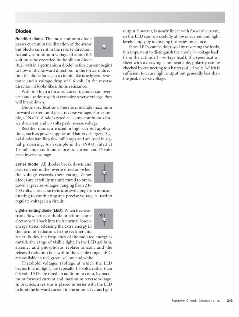
243Passive Circuit Components
DiodesRectifier diode. The most common diodepasses current in the direction of the arrowbut blocks current in the reverse direction.Actually, a minimum voltage of about 0.6volt must be exceeded in the silicon diode(0.25 volt in a germanium diode) before current beginsto flow in the forward direction. In the forward direc-tion the diode looks, to a circuit, like nearly zero resis-tance and a voltage drop of 0.6 volt. In the reversedirection, it looks like infinite resistance.
With too high a forward current, diodes can over-heat and be destroyed; at excessive reverse voltage, theywill break down.
Diode specifications, therefore, include maximumforward current and peak reverse voltage. For exam-ple, a 1N4001 diode is rated at 1-amp continuous for-ward current and 50 volts peak reverse voltage.
Rectifier diodes are used in high-current applica-tions, such as power supplies and battery chargers. Sig-nal diodes handle a few milliamps and are used in sig-nal processing. An example is the 1N914, rated at10-milliamps continuous forward current and 75 voltspeak inverse voltage.
Zener diode. All diodes break down andpass current in the reverse direction whenthe voltage exceeds their rating. Zenerdiodes are carefully manufactured to breakdown at precise voltages, ranging from 2 to200 volts. The characteristic of switching from noncon-ducting to conducting at a precise voltage is used toregulate voltage in a circuit.
Light-emitting diode (LED). When free elec-trons flow across a diode junction, someelectrons fall back into their normal, lower-energy states, releasing the extra energy inthe form of radiation. In the rectifier andzener diodes, the frequency of the radiated energy isoutside the range of visible light. In the LED gallium,arsenic, and phosphorus replace silicon, and thereleased radiation falls within the visible range. LEDsare available in red, green, yellow, and white.
Threshold voltages (voltage at which the LEDbegins to emit light) are typically 1.5 volts, rather than0.6 volt. LEDs are rated, in addition to color, by maxi-mum forward current and maximum reverse voltage.In practice, a resistor is placed in series with the LEDto limit the forward current to the nominal value. Light
output, however, is nearly linear with forward current,so the LED can run usefully at lower current and lightlevels simply by increasing the series resistance.
Since LEDs can be destroyed by reversing the leads,it is important to distinguish the anode (+ voltage lead)from the cathode (– voltage lead). If a specificationsheet with a drawing is not available, polarity can bechecked by connecting to a battery of 1.5 volts, which issufficient to cause light output but generally less thanthe peak inverse voltage.

244 Do-I t -Yourself Projects
NPN transistor. Transistors are usually explained interms of electrons and holes. I prefer a water analogy,which will serve our purposes well enough.
Figure 14.1 shows the three terminals of the NPNtransistor: base, collector, and emitter. The small arrowsshow the direction of current flow in the leads: IB, ICand IE. Note that the arrow in the emitter lead servesthe same purposes and distinguishes the NPN from thePNP transistor.
The transistor is constructed like a pair of diodesconnected back-to-back. Current IB will flow from thebase to the emitter, in the direction shown, wheneverthe base is at a higher voltage than the emitter.
Now the analogy—the base acts like a valve in thecollector-to-emitter waterpipe. A small change in IBresults in a large change in IC and IE. The ratio of cur-rent changes is called the forward current gain:
hFE = ∆IC/∆IB
Typical values of hFE range from 20 to 100.The most common use of the transistor is to mul-
tiply current and, thus, increase the power of a signal.
PNP transistor. The PNP transistor functions in exactlythe same way as the NPN transistor, except that itsdiodes are reversed. Figure 14.2 shows the lead defini-tions and current directions in the PNP transistor. Dueto the reversal of diodes, current IB will now flowwhenever the base is negative relative to the emitter.Current gain is again defined as:
hFE = ∆IC/∆IB
The choice between PNP and NPN transistorsdepends on the supply voltage configuration of the cir-cuit.
MOSFET. Both the field effect transistor (FET) and themetal-oxide semiconductor field effect transistor(MOSFET) act like transistors, except that the control-ling input signal is a voltage rather than a current. Sincealmost no current flows into the input lead (the gate),the input resistance of the MOSFET is virtually infinite.FETs and MOSFETs are therefore primarily used wherehigh input resistance is required. Applications wherethis characteristic is especially useful are operationalamplifier inputs and digital voltmeters. Figure 14.3shows the circuit symbol and the pin designations ofthe IRF510 power MOSFET.
Active Circuit Components
IB
IC
IE
Base
Emitter
Collector
Rload
+12 volts
E
E
E
C
B
BC
C
B
BOTTOM VIEWS
IB
IC
IE
Base
Emitter
Collector
Rload
–12 volts
E
E
E
C
B
BC
C
B
BOTTOM VIEWS
D
S
G
GD
S
IRF510 MOSFET
Fig. 14.1 NPN Transistor
Fig. 14.2 PNP Transistor
Fig. 14.3 MOSFET (IRF510)

245Act ive Circuit Components
Operational amplifier. If we were to describe a perfectamplifier, its specifications would read:
• Voltage gain = ∞• Input resistance = ∞ Ω• Input offset voltage = 0 volts A real opamp, the LM353, costs less than $1.00 in
single quantity and has the following specifications:• Voltage gain >106
• Input resistance = 1012Ω• Input offset voltage < 0.002 volt The usefulness of the opamp derives from its essen-
tially infinite voltage gain and input resistance. Figure14.4A shows the basic opamp. Since the output volt-age is limited by the supply voltage (usually ±15 VDC,although single-voltage operation is possible too), infi-nite voltage gain implies zero volts between the positive(Vin+) and negative (Vin–) inputs. Further, since theinput resistance is infinite, no current flows into eitherinput.
Figure 14.4B shows the opamp as a voltage follower.
Zero difference voltage means that Vin+ = Vin–, andsince Vout = Vin–, then Vout = Vin. The voltage followeris used to simply boost current while maintaining volt-age.
Figure 14.4C shows an inverting amplifier withvoltage gain. Since no current flows into the – input,and since the – input is at the same potential as the +input (ground), then the input current flowingthrough R1 must cancel the feedback current throughR2: I1 = –I2.
Then, using Ohm’s Law,
I = V/R,V1/R1 = –V2/R2
V2 = –V1(R2/R1)
Figure 14.4 shows a variety of other useful opampconfigurations (D, E, F). To understand how they work,you need remember only that Vin+ = Vin–.
The equation relating Vout to Vin can then bederived from equating the input and (negative) feed-back currents flowing into each input.
–
+
–
+
VoutVin –
Vin +Vin
RL Vout
–
+
Vin Vout
R1
R2
–
+
Vout
Vin
–
+
V1
Vout
R1 R2
R2
–
+
V1
Vout
Rf
R1
Rn
R2
R1
V2
VnV2
R1
R2
B. Unity-Gain Voltage Follower:A. Basic Operational Amplifier
D. Non-Inverting Amplifier
F. Difference AmplifierVout = – (V1 – V2)R2/R1Vout = – (Rf/R1 x V1 + Rf/R2 x V2 + ...)
Vout = Vin(R2/R1)Vout = – Vin
Vout = Vin
C. Inverting Amplifier
E. Summing Amplifier
Fig. 14.4 A Few Useful Operational Amplifier Circuits

246 Do-I t -Yourself Projects
1. AC Polarity Indicator The ABYC recommends reverse-polarity indicators onall AC main panels. It also suggests that the resistanceof such indicators be at least 25,000 ohms in order thatthey not bypass any isolation transformer or galvanicisolation diodes installed in the shore-power circuit.This two-lamp circuit consists of a green neon lampacross the hot and neutral conductors and a red neonlamp across neutral and ground. Proper polarity isindicated by a green light alone. If the red light comeson, either alone or with the green, something is wrong.To install the lamps, drill 5⁄16-inch holes in the distribu-tion panel and press in.
ComponentsPart Description RadioShack #
N1 Green 120-volt neon lamp 272-708N2 Red 120-volt neon lamp 272-712R1 33 kΩ, 1⁄4-watt resistor 271-1341
Projects
Hot (black)
Neutral (white)
Ground (green)
N1Green
N2Red
R1 R1

247Projects
2. LED Panel IndicatorMany DC distribution panels come only with circuitbreakers or fuses, so it is difficult to tell at a glancewhether a circuit is on or off. Others come with bat-tery-draining incandescent indicator lamps. One ofthese low-current LED indicators can be installed onthe output side of each circuit breaker and fuse to indi-cate, with a soft glow, when the circuit is on. The LEDspecified consumes only 0.012 amp. Ten LEDs will con-sume 3 Ah of battery power per 24 hours. To install,drill press-fit holes in the panel adjacent to each fuseswitch or circuit breaker. Press in the LED and solderthe 1 kΩ resistor between the LED anode (see specifica-tion sheet for lead identification) and the hot termi-nal. Connect the LED cathode to the panel ground bus.
ComponentsPart Description RadioShack #
R 1 kΩ, 1⁄4-watt resistor 271-1321LED Red, T1 (3 mm), LED 276-026
12 VDC Branchcircuit
R
LED

248 Do-I t -Yourself Projects
3. AC Frequency MeterThe ABYC recommends an AC frequency meter on theAC distribution panel fed by any onboard generator.The zener diode in this circuit clips incoming 120-voltAC sine waves to 6.2-volt DC square waves. CapacitorC1 differentiates the square waves into positive andnegative pulses. Diode D1 shorts the negative pulses toground, but diode D2 passes the positive pulses, whichare then averaged by the inertia of the ammeter, M.
To calibrate, connect the circuit to shore power (60Hz), and adjust R2 until M reads exactly 60 mA.
ComponentsPart Description RadioShack #
R1 100 kΩ, 1⁄2-watt resistor 271-1131R2 10 kΩ, 1-turn potentiometer 271-1715C1 0.22 µF capacitor 272-1070D1, D2 1N914 signal diode 276-1122Z1 6.2 V zener diode 276-561M 0–100 µA panel meter none
Projects
Hot(black)
Neutral(white)
A
R1
Z1 D1 R2
D2C1
M

249Projects
4. Small Battery EliminatorIf you are tired of replacing expensive batteries in yourelectronics, you can make a “battery” that will supplyup to 1.5 amps at any voltage from 1.5 to 10 volts DC,drawing from your ship’s battery. The 317T is anadjustable, three-terminal, integrated-circuit voltageregulator in a package smaller than a dime.
To install, solder the circuit as shown, connect Vinto 12 VDC and adjust trimpot R until Vout reads thedesired voltage. Then connect Vout and Ground to thebattery terminals of the electronic equipment.
You may wish to pack the circuit into a cardboardor plastic cylinder of the same dimensions as the bat-tery you are replacing. An alternative is to wrap the cir-cuit in foam and then stuff it into the battery slot. If the317T gets too hot to touch, mount it on the optionalheat sink.
ComponentsPart Description RadioShack #
317T Adjustable voltage regulator 276-1778R 1kΩ trimpot 271-280* Optional heat sink (not shown) 276-1368
VIN VOUT
Adjust
Ship'sbattery
Ship'sground
317T
RRa
Rb
Load(to 1.5A)
ADJ
VIN
VIN
VOUT
ADJ
CASE IS OUT
TO-220TO3Bottom View

250 Do-I t -Yourself Projects
5. Low-Battery Voltage AlarmIn this circuit a 741 operational amplifier comparesthe voltage of zener diode, Z, to a voltage determinedby the ship’s battery and the voltage divider, R3 and R2.
When the battery voltage falls below the presetlower-voltage limit, the voltage at the opamp’s Vin– ter-minal drops below the zener’s 6.2 volts, and the out-put of the opamp rises to the battery voltage, lightingthe LED. A 10-milliamp Piezo buzzer could replace thenoiseless LED for an audible alarm.
To set the battery’s low-voltage alarm point, moni-tor the battery voltage with a digital voltmeter. Whenthe voltage reaches 12.00 volts, for example, adjust R3until the LED or buzzer just comes on.
A two-stage alarm can easily be constructed, whichwill give a visual LED warning at 50% discharge, forexample, and a more dire audible warning at 75% dis-charge.
To construct, replace the 741 with a 1458 dual oper-ational amplifier, feed the – input of the second ampli-fier with a second R2/R3 voltage divider, and drive thePiezo buzzer with the output of the second amplifier.Calibrate the two setpoints as before, using a digitalvoltmeter to monitor battery voltage.
ComponentsPart Description RadioShack #
R1 10 kΩ, 1⁄4-watt resistor 271-1335R2 1 kΩ, 1⁄4-watt resistor 271-1321R3 10 kΩ, 15-turn trimpot 271-343R4 1 kΩ, 1⁄4-watt resistor 271-1321Z 1N4735, 6.2 V zener diode 276-561LED Red, T1 (3 mm), LED 276-026741 741 operational amplifier 276-007
Projects
–
+
R3
R2
R4
Z
R1
LED
741
2
3 7
4
6
+12V
Battery

251Projects
6. Expanded-Scale Analog Battery MonitorThe problem with monitoring battery voltage with ananalog panel meter is that the normal 5% accuracy ofthe meter is equivalent to about 50% of the battery’scapacity. What is needed is an electronic magnifyingglass to focus on the battery’s 11.7- to 12.7-volt range.
In this circuit, a 317T adjustable voltage regulatoris used to provide a constant 11.70 VDC. The 0- to 1-volt DC voltmeter then reads the difference betweenthe ship’s battery voltage and the reference 11.70 volts.Assuming 12.70 and 11.70 volts represent 100% and0% charge, 0 to 1 volt on the voltmeter represents 0%to 100% charge.
The 3 VDC alkaline battery (can be two AA alka-line cells in a battery holder) boosts the regulatorsource so that the output can still deliver 11.7 volts,even when the ship’s battery drops to 11.7 volts.
The 0- to 1-volt voltmeter can be replaced by Roptand an ammeter, as shown in the component list.
Of course a digital voltmeter may be used, in lieuof the analog meter.
ComponentsPart Description RadioShack #
317T Adjustable voltage regulator 276-1778R 1 kΩ, 15-turn trimpot 271-342M 0–1-volt DC meter noneRopt 10 kΩ resistor for 100 µA meter 271-1335Ropt 1 kΩ resistor for 1 µA meter 271-1321
+
–V
VIN VOUT
11.7V
Adjust
317T
(11.7–12.7V)
3V
ROPT
R
M
Battery
ADJ
VIN
VIN
VOUT
ADJ
CASE IS OUT
TO-220TO3Bottom View
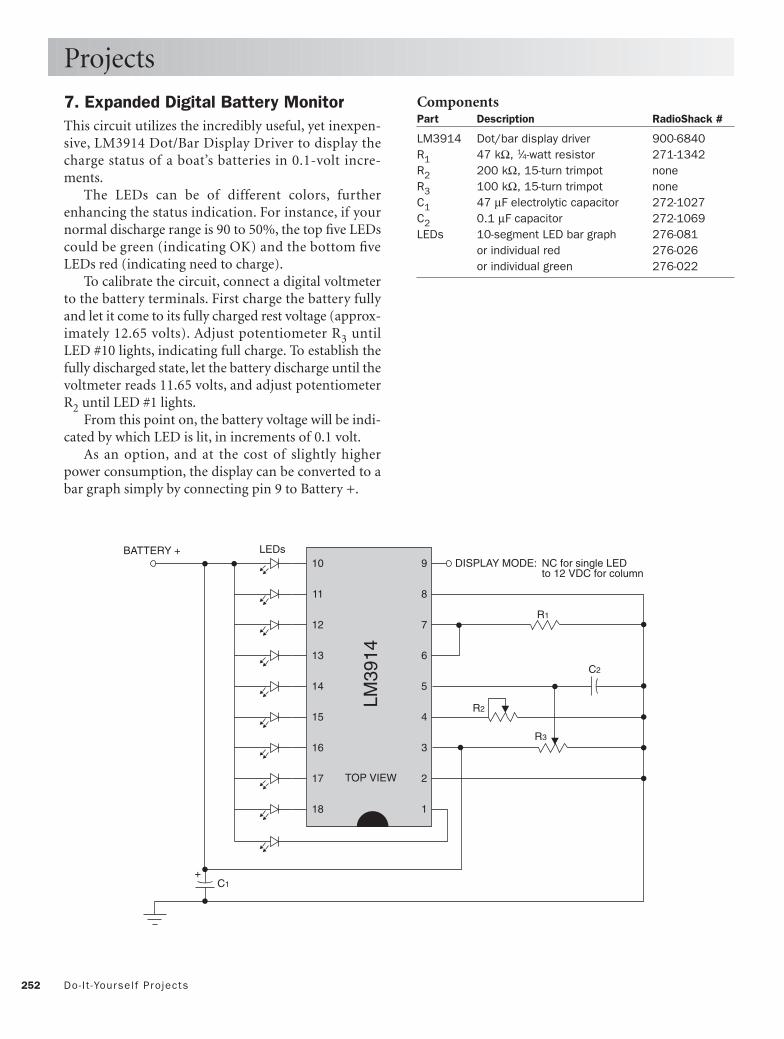
252 Do-I t -Yourself Projects
7. Expanded Digital Battery MonitorThis circuit utilizes the incredibly useful, yet inexpen-sive, LM3914 Dot/Bar Display Driver to display thecharge status of a boat’s batteries in 0.1-volt incre-ments.
The LEDs can be of different colors, furtherenhancing the status indication. For instance, if yournormal discharge range is 90 to 50%, the top five LEDscould be green (indicating OK) and the bottom fiveLEDs red (indicating need to charge).
To calibrate the circuit, connect a digital voltmeterto the battery terminals. First charge the battery fullyand let it come to its fully charged rest voltage (approx-imately 12.65 volts). Adjust potentiometer R3 untilLED #10 lights, indicating full charge. To establish thefully discharged state, let the battery discharge until thevoltmeter reads 11.65 volts, and adjust potentiometerR2 until LED #1 lights.
From this point on, the battery voltage will be indi-cated by which LED is lit, in increments of 0.1 volt.
As an option, and at the cost of slightly higherpower consumption, the display can be converted to abar graph simply by connecting pin 9 to Battery +.
Projects
ComponentsPart Description RadioShack #
LM3914 Dot/bar display driver 900-6840R1 47 kΩ, 1⁄4-watt resistor 271-1342R2 200 kΩ, 15-turn trimpot noneR3 100 kΩ, 15-turn trimpot noneC1 47 µF electrolytic capacitor 272-1027C2 0.1 µF capacitor 272-1069LEDs 10-segment LED bar graph 276-081
or individual red 276-026or individual green 276-022
9
8
7
6
5
4
3
2
1
+
10
11
12
BATTERY + LEDs
13
14
15
16
17
18
DISPLAY MODE: NC for single LEDto 12 VDC for column
TOP VIEW
LM39
14
R1
R3
R2
C2
C1

253Projects
8. Automatic Anchor LightThe typical mast-top anchor light consumes 12 watts.Over a 12-hour period, it will drain 12 Ah from the bat-tery. If you leave the boat unattended and leave theanchor light on (as you must legally), it will draw downthe battery at 24 Ah per day!
This circuit saves battery power by automaticallyswitching on at sunset and off at sunrise. At sunset, theresistance of the cadmium sulfide photoresistorincreases, increasing the voltage to the NPN transistor,Q. The transistor provides the current to close the coilof the relay and feed 12 VDC to the anchor light.
The red LED indicates when the anchor light is on.A single-pole, three-position rotary switch allows selec-tion between automatic, manual, and off modes.
Note that the cadmium sulfide photoresistor mustbe placed so that it is not illuminated by the anchorlight. Otherwise it will interpret the anchor light assunlight and cause the light to turn on and off rapidly.
ComponentsPart Description RadioShack #
R1 1 kΩ, 1⁄4-watt resistor 271-1321R2 10 kΩ, 1-turn potentiometer 271-282R3 1 kΩ, 1⁄4-watt resistor 271-1321P Photoresistor 276-1657Q 2N2222 NPN transistor 276-2009Relay 12 V, 400 Ω, 10 A SPDT 275-248SW SPDT switch, center Off 275-654LED Red, T1 (3 mm), LED 276-026741 741 operational amplifier 276-007
–
+
Auto
Off
Man
+12V2
3 4
7
6
P
R1 R2 R3
741
Q
Relay
SW
LED
Anchorlight

254 Do-I t -Yourself Projects
9. Cabin Light DimmerHalogen cabin lamps are great for reading, but not veryromantic for dining. Furthermore, dimming yourcabin lights will save on battery power.
The heart of this circuit is the integrated circuit 555timer. The 555 runs as a multivibrator (digital oscilla-tor) with its frequency determined by R1, R2, R3, andC1. Pin 3 of the 555 controls the gate of the MOSFET,Q, which supplies current to the cabin lamps in theform of square waves of modulated width.
The percentage of normal voltage supplying thelamps is equivalent to the percentage-on time of thepulses, which is controlled by adjusting trimpot R2.This effective voltage across the lamps can be variedfrom about 4.5 to 11.0 VDC.
The dimmer circuit is switched in and out of thecircuit by switch SW. Individual cabin lights can stillbe switched on and off with their own switches.
Since the life of the very expensive halogen lampsis extended markedly by reduction in supply voltage,you might consider leaving the dimmer circuit on allthe time, set at the minimum power level required forthe task at hand.
If the circuit load is more than 5 watts, check theoperating temperature of the 555. If too hot to touch,attach a heat sink to the integrated circuit.
ComponentsPart Description RadioShack #
R1 100 Ω, 1⁄4-watt resistor 271-1311R2 5 kΩ potentiometer 271-1714R3 1 kΩ, 1⁄4-watt resistor 271-1321R4 10 kΩ, 1⁄4-watt resistor 271-1335C1 0.047 µF capacitor 272-1068C2 22 µF capacitor 272-1026Q IRF-510 power MOSFET 276-2072555 555 timer integrated circuit 276-1723SW SPDT switch, center Off 275-654* Heat sink for Q (not shown) 276-1368
Projects
+
+
8 47
6
2 1
3
555
R1
R2
R3
R4C2
C1
Q D
SG
SW
Cabin lamp(s)(up to 30W with
heat sink)
+12V

255Projects
10. Bilge High-Water AlarmAutomatic bilge pump switches are notorious for fail-ing. Although not usually dangerous, having bilgewater rise above the cabin sole is not very good for therugs or the joinery. This circuit gives an audible warn-ing when the bilge water rises to the level of the nor-mally dry probe.
The 741 opamp acts as a voltage comparator. The –input voltage is set at +6 VDC by the voltage dividerformed by R2 and R3. With a dry probe, the + inputvoltage is near 0 VDC, so the output of the 741 is near0 VDC.
With the probe immersed in water, however, thevoltage at the + input rises to over 6 VDC, and the 741output goes to 12 VDC. Transistor Q boosts the out-put of the 741 to drive the Piezo transducer. R4 pre-vents the + side of the probe from shorting to groundthrough the bilge water.
An inexpensive and convenient probe can be madefrom a section of television twin lead with each con-ductor stripped back about 1 inch and tinned (sol-dered) to prevent corrosion. The probes should bemounted well above the normal bilge high-water level,so that they remain dry except when the regular bilgeswitch fails.
ComponentsPart Description RadioShack #
R1 100 kΩ, 1⁄4-watt resistor 271-1347R2 100 kΩ 1⁄4-watt resistor 271-1347R3 100 kΩ, 1⁄4-watt resistor 271-1347R4 10 kΩ, 1⁄4-watt resistor 271-1335Q 2N2222 NPN transistor 276-2009741 741 operational amplifier 276-007SP Piezo transducer 273-075Probe TV twin-lead antenna wire 15-0004
R4
Q
–
+
R3
R2
R1 SP
741
2
3 7
4
6
+12V
Probe

256 Do-I t -Yourself Projects
11. Water Tank MonitorFew things are more annoying than unexpectedly run-ning out of water or having to lift deck hatches andunscrew access plates to check the level of water in yourtanks. This circuit gives a visual warning when yourwater tank reaches a predetermined level.
The 741 operational amplifier acts as a voltage com-parator. The + input voltage is set by the voltage dividerformed by trimpot R2.
Run a length of television twin-lead antenna cableinto your water tank from above. Strip about 1 inch ofinsulation from each of the two conductors and solderthe exposed wire to prevent corrosion.
With the probe immersed in water, the voltage atthe – input is near +12 VDC. As soon as the water leveldrops below the probe leads, the resistance between theleads increases to near infinity and the – input voltagedrops to zero. The amplifier output rises to the supplyvoltage and lights the LED warning light.
Add a switch to the +12 VDC power lead if youdon’t wish to monitor the tank continuously.
Projects
ComponentsPart Description RadioShack #
R1 220 kΩ, 1⁄4-watt resistor 271-1350R2 100 kΩ trimpot 271-284R3 1 kΩ, 1⁄4-watt resistor 271-1321LED Red, T1 (3 mm), LED 276-026741 741 operational amplifier 276-007
12. Electronic Ship’s HornThe circuit is a multivibrator (Q1 and Q2) with a fre-quency of 2π/R1C1 = 280 Hz. Transistor Q3 boosts theoutput current to drive the 8 Ω, 25-watt speaker. Push-ing the momentary contact switch, SW1, sounds thehorn.
Play with resistors R1 to achieve the pitch that ismost pleasing to you, although 280 Hz is close to thefrequency of most commercial horns. A speaker withhigher impedance can be used with an impedance-matching transformer.
Using switch SW2, the speaker can be connected tothe hailer output found in the rear of many VHF radios,allowing the speaker to be used as a bullhorn as well.
ComponentsPart Description RadioShack #
R1(2) 100 kΩ, 1⁄4-watt resistor 271-1347R2(2) 1 kΩ, 1⁄4-watt resistor 271-1321C1(2) 0.22 µF capacitor 272-1070Q1 2N2222 NPN transistor 276-2009Q2 2N2222 NPN transistor 276-2009Q3 TIP-3055 NPN power transistor 276-2020SW1 Momentary contact switch 275-609SW2 DPDT switch, 6 A 275-652SP Power horn, 8Ω, 25-watt 40-1440
R1 R2 R1 R2
Q1
Q2
Q3
C1
C1
SW2
SW1 Push to sound horn
To output of VHF hailer
+12V
–
+R2 R3R1
LED
741
2
3
7
4
6
+12V
Probe

257Projects
13. Refrigeration Fan ControlThe efficiency of a refrigerator is affected greatly bythe temperature of its condenser coil. Many small, 12VDC boat compressors are located in warm or con-stricted spaces. Such condensers need fans to removethe heat from the coils.
This circuit uses a tiny thermistor, taped to the con-denser tubing, to detect the need for air flow. The tapeover the thermistor protects it from the direct flow ofcool air, so that it measures the temperature of the coilrather than that of the moving air.
The opamp compares the voltages of two voltagedividers formed by R1/RT (– input) and trimpot R2(+ input). When the temperature of the thermistorrises above the set point, its resistance drops, the volt-age at the negative input drops, and the output voltageof the inverting amplifier rises. Transistor Q boosts theopamp output current to close the relay and turn onthe fan.
The temperature at which the fan comes on (theset point) is adjusted with trimpot R2. Trimpot R3adjusts the gain of the amplifier and, thus, the hystere-sis, or difference between turn-on and turn-off temper-atures.
ComponentsPart Description RadioShack #
R1 10 kΩ, 1⁄4-watt resistor 271-1335R2 20 kΩ, 15-turn trimpot 900-8583R3 100 kΩ trimpot 271-284T Thermistor, 10 kΩ @ 25˚C 271-110Q 2N2222 NPN transistor 276-2009K 12 V, 400 Ω, 10 A SPDT relay 275-248741 741 operational amplifier 276-007F Blower fan, 12 VDC 273-243
–
+R2
R1
741
2
3
7
4
6
+12V
F
R3
T
R4Q
K

Appendices
258
Because boats are built and wired throughout theworld we felt the least we could offer boatownerswould be a listing of other wiring standards in
use in the United States, Canada, and the EuropeanUnion, and a table of metric conversions.
The formula for converting from Celsius to Fahren-heit degrees is awkward and difficult to compute inyour head, so we thought a table of temperature con-versions would be useful. Similarly, in wiring there isoften need to perform power conversions from themechanical horsepower of motors to electrical watts.
Both copper conductors and coaxial cables sufferlosses as functions of length. Therefore, we haveincluded handy tables of resistance of copper wire andlosses in coaxial cables.
Although DC and AC color codes for marine wiringare discussed in the text, other wiring color codes exist,so we thought it would be useful to present them alltogether.
When performing electronic installation and repair,it is often necessary to identify the characteristics ofcomponents. With the trend toward miniaturization, itis increasingly difficult for manufacturers to print, andfor us to read, information directly on the component.This is especially true for resistors and capacitors. Thusthe manufacturers have resorted to cryptic codesinvolving colors and single alphanumeric characters asaids in identifying resistors and identifying capacitors.
Finally, for the mathematically inclined, we offer allof the useful electrical formulas and trigonometrictables you might need in performing electrical calcula-tions.
Copyright © 1993, 2006 by Charlie Wing. Click here for terms of use.

259Other Wir ing Standards
Boatowner’s Illustrated Electrical Handbook is based onthe American Boat and Yacht Council (ABYC) Stan-dards and Recommended Practices for Small Craft, a setof standards almost universally followed in the UnitedStates and increasingly referenced throughout theworld. Most of the dozens of other standards in usearound the world are remarkably similar, so you wouldnot go far astray in following the ABYC recommenda-tions. If you need to reference one of the other stan-dards, however, here is a list of the most importantones.
United StatesThe United States Coast Guard: Title 33, CFR 183.These contain federal mandatory requirements forelectrical systems on boats. Many of the Title 33 regula-tions are directly referenced in the ABYC standards.In no case do the two conflict. The text is available onthe web at: www.access.gpo.gov/nara/cfr/waisidx_99/33cfr183_99.html.
National Marine Electronics Association (NMEA):Installation Standards. This standard is for the installa-tion of marine electronics, primarily on large vessels.It is complementary to the ABYC recommendations,but with an emphasis on electronics. To visit NMEA onthe web, go to: www.nmea.org.
National Fire Protection Association (NFPA): NationalElectrical Code (NEC). This is the single United States national code governing all wiring on land,including marinas. To visit NFPA on the web, go to:www.nfpa.org.
CanadaTransport Canada: TP1332 E—Construction Standardsfor Small Vessels—Section 8 Electrical Systems. The sin-gle, comprehensive set of standards for pleasure ves-sels constructed in Canada. The complete text can beaccessed at: www.tc.gc.ca/marinesafety/TP/TP1332/menu.htm.
European UnionEuropean Recreational Craft Directive (RCD). RCDstandards are mandatory on boats constructed in Euro-pean Union (EU) countries and include the followingInternational Standards Organization (ISO) standards:
ISO10133:2000. Small Craft—Electrical systems—Extra-low-voltage DC installations.ISO13297:2000. Small Craft—Electrical systems—AC installations.ISO8846:1990 Small Craft—Electrical devices—Pro-tection against ignition of surrounding flammablegas.
ISO standards can be purchased online at: www.iso.org/iso/en/prods-services/ISOstore/store.html.
Lloyd’s Register. Rules and Regulations for the Classifica-tion of Yachts and Small Craft, 1978.The Rules are used when a boat is to be built to Lloyd’sRegister (LR) Class rules.
BMEA (British Marine Electronics Association): Codeof Practice for Electrical and Electronic Installations inSmall Craft—4th Edition. This standard is similar to theUnited States NMEA Installation Standards and is avail-able direct from the British Marine Federation Techni-cal Department; tel: 01784 223634 or email: [email protected].
Other Wiring Standards

260 Appendices
English/Metric Conversions
English to Metric Metric to EnglishMultiply By To Get Multiply By To Get
LENGTH
Inches 25.4 Millimeters Millimeters 0.0394 Inches
Inches 2.54 Centimeters Centimeters 0.3937 Inches
Inches 0.0254 Meters Meters 39.37 Inches
Feet 30.48 Centimeters Centimeters 0.0328 Feet
Feet 0.3048 Meters Meters 3.281 Feet
Yards 0.9144 Meters Meters 1.094 Yards
Miles 1.609 Kilometers Kilometers 0.6215 Miles
AREA
Inches2 645.16 Millimeters2 Millimeters2 0.00155 Inches2
Inches2 6.4516 Centimeters2 Centimeters2 0.155 Inches2
Feet2 929.03 Centimeters2 Centimeters2 0.00108 Feet2
Feet2 0.0929 Meters2 Meters2 10.764 Feet2
Yards2 8361.3 Centimeters2 Centimeters2 0.00012 Yards2
Yards2 0.8361 Meters2 Meters2 1.196 Yards2
Miles2 2.59 Kilometers2 Kilometers2 0.3861 Miles2
VOLUME
Inches3 16.387 Millimeters3 Millimeters3 6.1 x 10⁻⁵ Inches3
Inches3 16.387 Centimeters3 Centimeters3 0.061 Inches3
Feet3 0.0283 Meters3 Meters3 35.33 Feet3
Yards3 0.7646 Meters3 Meters3 1.308 Yards3
ENERGY
Ergs 10–7 Newton-meters Newton-meters 107 Ergs
Joules 1 Newton-meters Newton-meters 1 Joules
Joules 107 Ergs Ergs 10–7 Joules
Joules 0.2389 Calories Calories 4.186 Joules
Joules 0.000948 Btu Btu 1,055 Joules
Joules 0.7376 Foot-pounds Foot-pounds 1.356 Joules
Calories 0.00397 Btu Btu 252 Calories
Joules/see 3.41 Btu/hr Btu/hr 0.293 Joules/see
Btu/hr 252 Calories/hr Calories/hr 0.00397 Btu/hr
Horsepower 746 Watts Watts 0.00134 Horsepower
F° 0.556 C° C° 1.8 F°
°F 0.556 (°F – 32) °C °C 1.8 x °C + 32 °F
Table A1 English to Metric Conversions

261Temperature Conversions
Temperature ConversionsTable A2 Fahrenheit Degrees to Celsius Degrees Conversion1
1 °C = (°F – 32)/1.8
212 100
211 99.4
210 98.9
209 98.3
208 97.8
207 97.2
206 96.7
205 96.1
204 95.6
203 95.0
202 94.4
201 93.9
200 93.3
199 92.8
198 92.2
197 91.7
196 91.1
195 90.6
194 90.0
193 89.4
192 88.9
191 88.3
190 87.8
189 87.2
188 86.7
187 86.1
186 85.6
185 85.0
184 84.4
183 83.9
182 83.3
181 82.8
180 82.2
179 81.7
178 81.1
177 80.6
176 80.0
175 79.4
174 78.9
173 78.3
172 77.8
171 77.2
170 76.7
169 76.1
168 75.6
167 75.0
166 74.4
165 73.9
164 73.3
163 72.8
162 72.2
161 71.7
160 71.1
159 70.6
158 70.0
157 69.4
156 68.9
155 68.3
154 67.8
153 67.2
152 66.7
151 66.1
150 65.6
149 65.0
148 64.4
147 63.9
146 63.3
145 62.8
144 62.2
143 61.7
142 61.1
141 60.6
140 60.0
139 59.4
138 58.9
137 58.3
136 57.8
135 57.2
134 56.7
133 56.1
132 55.6
131 55.0
130 54.4
129 53.9
128 53.3
127 52.8
126 52.2
125 51.6
124 51.1
123 50.5
122 50.0
121 49.4
120 48.8
119 48.3
118 47.7
117 47.2
116 46.6
115 46.1
114 45.5
113 45.0
112 44.4
111 43.8
110 43.3
109 42.7
108 42.2
107 41.6
106 41.1
105 40.5
104 40.0
103 39.4
102 38.9
101 38.3
100 37.7
99 37.2
98 36.6
97 36.1
96 35.5
95 35.0
94 34.4
93 33.9
92 33.3
91 32.7
90 32.2
89 31.6
88 31.1
87 30.5
86 30.0
85 29.4
84 28.9
83 28.3
82 27.8
81 27.2
80 26.6
79 26.1
78 25.5
77 25.0
76 24.4
75 23.9
74 23.3
73 22.8
72 22.2
71 21.6
70 21.1
69 20.5
68 20.0
67 19.4
66 18.9
65 18.3
64 17.8
63 17.2
62 16.7
61 16.1
60 15.5
59 15.0
58 14.4
57 13.9
56 13.3
55 12.8
54 12.2
53 11.7
52 11.1
51 10.5
50 10.0
49 9.4
48 8.9
47 8.3
46 7.8
45 7.2
44 6.7
43 6.1
42 5.6
41 5.0
40 4.4
39 3.9
38 3.3
37 2.8
36 2.2
35 1.7
34 1.1
33 0.6
32 0.0
31 –0.6
30 –1.1
29 –1.7
28 –2.2
27 –2.8
26 –3.3
25 –3.9
24 –4.4
23 –5.0
22 –5.6
21 –6.1
20 –6.7
19 –7.2
18 –7.8
17 –8.3
16 –8.9
15 –9.4
14 –10.0
13 –10.5
12 –11.1
11 –11.7
10 –12.2
9 –12.8
8 –13.3
7 –13.9
6 –14.4
5 –15.0
4 –15.5
3 –16.1
2 –16.7
1 –17.2
0 –17.8
–1 –18.3
–2 –18.9
–3 –19.4
–4 –20.0
–5 –20.5
–6 –21.1
–7 –21.6
–8 –22.2
–9 –22.8
–10 –23.3
–11 –23.9
–12 –24.4
–13 –25.0
–14 –25.5
–15 –26.1
–16 –26.6
–17 –27.2
–18 –27.8
–19 –28.3
–20 –28.9
–21 –29.4
–22 –30.0
–23 –30.5
–24 –31.1
–25 –31.6
–26 –32.2
–27 –32.7
–28 –33.3
–29 –33.9
–30 –34.4
–31 –35.0
–32 –35.5
–33 –36.1
–34 –36.6
–35 –37.2
–36 –37.7
–37 –38.3
–38 –38.9
–39 –39.4
F° C°F° C° F° C° F° C° F° C° F° C°

262 Appendices
Power ConversionsTable A3 Kilowatts (kW) to Horsepower (hp) Conversion1
HP kW
0.1 0.13
0.2 0.27
0.3 0.40
0.4 0.54
0.5 0.67
0.6 0.80
0.7 0.94
0.8 1.07
0.9 1.21
1 1.34
2 2.68
3 4.02
4 5.36
5 6.71
6 8.05
7 9.39
8 10.7
9 12.1
10 13.4
11 14.8
12 16.1
13 17.4
14 18.8
15 20.1
16 21.5
17 22.8
18 24.1
19 25.5
20 26.8
21 28.2
22 29.5
23 30.8
24 32.2
25 33.5
26 34.9
27 36.2
HP kW
28 37.5
29 38.9
30 40.2
31 41.6
32 42.9
33 44.3
34 45.6
35 46.9
36 48.3
37 49.6
38 51.0
39 52.3
40 53.6
41 55.0
42 56.3
43 57.7
44 59.0
45 60.3
46 61.7
47 63.0
48 64.4
49 65.7
50 67.1
51 68.4
52 69.7
53 71.1
54 72.4
55 73.8
56 75.1
57 76.4
58 77.8
59 79.1
60 80.5
61 81.8
62 83.1
63 84.5
HP kW
64 85.8
65 87.2
66 88.5
67 89.8
68 91.2
69 92.5
70 93.9
71 95.2
72 96.6
73 97.9
74 99.2
75 101
76 102
77 103
78 105
79 106
80 107
81 109
82 110
83 111
84 113
85 114
86 115
87 117
88 118
89 119
90 121
91 122
92 123
93 125
94 126
95 127
96 129
97 130
98 131
99 133
HP kW
0.1 0.07
0.2 0.15
0.3 0.22
0.4 0.30
0.5 0.37
0.6 0.45
0.7 0.52
0.8 0.60
0.9 0.67
1 0.75
2 1.49
3 2.24
4 2.98
5 3.73
6 4.47
7 5.22
8 5.97
9 6.71
10 7.46
11 8.20
12 8.95
13 9.69
14 10.4
15 11.2
16 11.9
17 12.7
18 13.4
19 14.2
20 14.9
21 15.7
22 16.4
23 17.2
24 17.9
25 18.6
26 19.4
27 20.1
HP kW
28 20.9
29 21.6
30 22.4
31 23.1
32 23.9
33 24.6
34 25.4
35 26.1
36 26.8
37 27.6
38 28.3
39 29.1
40 29.8
41 30.6
42 31.3
43 32.1
44 32.8
45 33.6
46 34.3
47 35.0
48 35.8
49 36.5
50 37.3
51 38.0
52 38.8
53 39.5
54 40.3
55 41.0
56 41.8
57 42.5
58 43.3
59 44.0
60 44.7
61 45.5
62 46.2
63 47.0
HP kW
64 47.7
65 48.5
66 49.2
67 50.0
68 50.7
69 51.5
70 52.2
71 52.9
72 53.7
73 54.4
74 55.2
75 55.9
76 56.7
77 57.4
78 58.2
79 58.9
80 59.7
81 60.4
82 61.1
83 61.9
84 62.6
85 63.4
86 64.1
87 64.9
88 65.6
89 66.4
90 67.1
91 67.9
92 68.6
93 69.4
94 70.1
95 70.8
96 71.6
97 72.3
98 73.1
99 73.8
1 1 kW = 1.341 hp
Table A4 Horsepower (hp) to Kilowatts (kW) Conversion1
1 1 hp = 0.7457 kW

263Resistance of Copper Wire
Resistance of Copper WireTable A5 Resistance of Copper Wire at 77°F (25°C)
AWG Feet/Ohm Ohms/1,000 Feet
0000 20,000 0.050
000 15,873 0.063
00 12,658 0.079
0 10,000 0.100
1 7,936 0.126
2 6,289 0.159
3 4,975 0.201
4 3,953 0.253
5 3,135 0.319
6 2,481 0.403
7 1,968 0.508
8 1,560 0.641
9 1,238 0.808
10 980.4 1.02
11 781.3 1.28
12 617.3 1.62
13 490.2 2.04
14 387.6 2.58
15 307.7 3.25
16 244.5 4.09
17 193.8 5.16
18 153.6 6.51
19 121.8 8.21
20 96.2 10.4
21 76.3 13.1
22 60.6 16.5
23 48.1 20.8
24 38.2 26.2
25 30.3 33.0
26 24.0 41.6
27 19.0 52.5
28 15.1 66.2
29 12.0 83.4
30 9.5 105
AWG Feet/Ohm Ohms/1,000 Feet
0000 17,544 0.057
000 13,699 0.073
00 10,870 0.092
0 8,621 0.116
1 6,849 0.146
2 5,435 0.184
3 4,310 0.232
4 3,425 0.292
5 2,710 0.369
6 2,151 0.465
7 1,706 0.586
8 1,353 0.739
9 1,073 0.932
10 847.5 1.18
11 675.7 1.48
12 534.8 1.87
13 423.7 2.36
14 336.7 2.97
15 266.7 3.75
16 211.4 4.73
17 167.8 5.96
18 133.2 7.51
19 105.5 9.48
20 84.0 11.9
21 66.2 15.1
22 52.6 19.0
23 41.7 24.0
24 33.1 30.2
25 26.2 38.1
26 20.8 48.0
27 16.5 60.6
28 13.1 76.4
29 10.4 96.3
30 8.3 121
Table A6 Resistance of Copper Wire at 149°F (65°C)

264 Appendices
Losses in Coaxial Cables
Signal Cable TypeFrequency RG-6 RG-8X RG-11 RG-58 RG-174 RG-213 RF-9913 RF-9914
1 MHz 0.2 dB 0.5 dB 0.2 dB 0.4 dB 1.9 dB 0.2 dB 0.2 dB 0.3 dB
10 MHz 0.6 dB 1.0 dB 0.4 dB 1.4 dB 3.3 dB 0.6 dB 0.4 dB 0.5 dB
50 MHz 1.4 dB 2.5 dB 1.0 dB 3.3 dB 6.6 dB 1.6 dB 0.9 dB 1.1 dB
100 MHz 2.0 dB 3.6 dB 1.6 dB 4.9 dB 8.9 dB 2.2 dB 1.4 dB 1.5 dB
200 MHz 2.8 dB 5.4 dB 2.3 dB 7.3 dB 11.9 dB 3.3 dB 1.8 dB 2.0 dB
400 MHz 4.3 dB 7.9 dB 3.5 dB 11.2 dB 17.3 dB 4.8 dB 2.6 dB 2.9 dB
700 MHz 5.6 dB 11.0 dB 4.7 dB 16.9 dB 26.0 dB 6.6 dB 3.6 dB 3.8 dB
900 MHz 6.0 dB 12.6 dB 5.4 dB 20.1 dB 27.9 dB 7.7 dB 4.2 dB 4.9 dB
1 GHz 6.1 dB 13.5 dB 5.6 dB 21.5 dB 32.0 dB 8.3 dB 4.5 dB 5.3 dB
Impedance 75 ohm 50 ohm 75 ohm 50 ohm 50 ohm 50 ohm 50 ohm 50 ohm
Loss in Power VoltageDecibels (dB) Ratio Ratio
0.0 1.000 1.000
0.5 0.891 0.944
1.0 0.794 0.891
1.5 0.708 0.841
2.0 0.631 0.794
2.5 0.562 0.750
3.0 0.501 0.708
3.5 0.447 0.668
4.0 0.398 0.631
4.5 0.355 0.596
5.0 0.316 0.562
6.0 0.251 0.501
7.0 0.200 0.447
8.0 0.158 0.398
9.0 0.126 0.355
10 0.100 0.316
20 0.010 0.100
30 0.001 0.032
40 0.0001 0.010
Table A7 Signal Loss (Attenuation) in Decibels (dB) per 100 Feet in Coaxial Cables
Table A8 Signal Loss in Decibels (dB) in Coaxial Cables

265Wir ing Color Codes
Wiring Color CodesTable A9 Marine DC Wiring Color Code (Adapted from ABYC Standard E-11, Tables XIV and XV)
Color Conductor Use
Green or green with General DC grounding yellow stripe(s)Black or yellow General DC negativeRed General DC positiveYellow with red stripe Starter switch to solenoidBrown with yellow Fuse or switch to blower—If DCstripe, or yellow negative is yellow, positive must
be brown with yellow stripeDark gray Fuse or switch to navigation lights
Tachometer sender to gaugeBrown Generator armature to regulator
Auxiliary terminal to light and regu-latorFuse or switch to pumps
Orange Ammeter to alternator or generatoroutput and accessory fuses orswitchesDistribution panel to accessoryswitch
Purple Ignition switch to coil and electrical instrumentsDistribution panel to electricalinstruments
Dark blue Fuse or switch to cabin and instru-ment lights
Light blue Oil-pressure sender to gaugeTan Water-temperature sender to gaugePink Fuel-gauge sender to gaugeGreen/stripe, Tilt and/or trim circuitsexcept G/Y
Table A10 Marine AC Wiring Color Code (Adapted from ABYC Standard E-11, Tables XIV and XV)
Conductor Colors (Preferred First)
Ungrounded Black or brownGrounded neutral White or light blueGrounding Green, green with yellow stripeAdditional ungrounded Red, blue, orange
Black with red stripeBlack with blue stripeBlack with orange stripe
Table A11 Electronic Wiring Color Code (from the Electronic Industries Association [EIA])
Color Conductor Use
Black Ground, DC negative Blue Transistor collector, FET drainBrown FilamentGray AC main powerGreen Transistor base, diode, FET gate Orange Transistor base 2Red DC+ power supplyViolet DC– power supplyWhite B-C minus bias supply, AVC-AGC returnYellow Transistor emitter, FET source
Table A12 Power Transformer Color Code
Color Conductor Use
Black Both leads of an untapped primary Black Common lead of tapped primaryBlack/Yellow Tap of tapped primaryBlack/Red End of tapped primary
Table A13 Audio Transformer Color Code
Color Conductor Use
Black Ground Blue End of primaryBrown End of primary opposite blueGreen End of secondaryRed B+, center tap of push-pull loopYellow Center tap of secondary
Table A14 Stereo Channel Color Code
Color Conductor Use
White Left channel high Blue Left channel lowRed Right channel highGreen Right channel low

266 Appendices
Useful Electrical Formulas
Direct Current (DC)
Ohm’s Law
where:V = voltage, voltsI = current, amperes (amps)
R = resistance, ohmsP = power, watts
V = I × R= P/I= (P × R)1⁄2
I = V/R= P/V= (P/R)1⁄2
R = V/I= P/I2
P = I2 × R= V × I= V2/R
Resistors
In Series: R = R1 + R2 + R3 + . . .In Parallel: R = 1/(1/R1 + 1/R2 + 1/R3 + . . .)
Capacitors
In Parallel: C = C1 + C2 + C3 + . . .In Series: C = 1/(1/C1 + 1/C2 + 1/C3 + . . .)Charge (coulombs) = C(farads) × V
Alternating Current (AC)
Ohm’s Law
where:V = voltage, voltsI = current, amperes (amps)
Z = impedance, ohmsP = power, wattsq = phase angle
V = I × Z= P/(I × cosq)= (P × Z/cosq)1⁄2
I = V/Z= P/(V × cosq) = P/(Z × cosq)1⁄2
Z = V/I= P/(I2 × cosq)
P = I2 × Z × cosq= V × I × cosq= V2 × cosq/Z
Reactance
where:XL = reactance of an inductor, ohmsXC = reactance of a capacitor, ohmsH = inductance, henrysC = capacitance, faradsF = frequency, Hertzπ = 3.14
XL = 2π × F × HXC = 1/(2π × F × C)
Impedance
In Series: Z = [R2 + (XL – XC )2]1⁄2
In Parallel: Z = R × X/(R2 + X2)1⁄2
Power Factor, pf
pf = True power/Apparent power= cosθ= P/(V × I)= R/Z

267Ident i fy ing Resistors
Resistors are generally too small to allow the imprint-ing of identifying information. For this reason standardresistors are coded with color bands.
Figure A1 and Table A15 demystify the color code.Example: What is the resistance of a resistor with brown,red, orange, and silver bands? Answer: 12,000 ±10% Ω.
Identifying Resistors
First significant digit
Second significant digit
Decimal multiplier
Tolerance:
silver = ±10%gold = ±5%
none = ±20%
Table A15 Resistor Color Codes
Band Power Decimal Color Digit of 10 Multiplier
Silver 10–2 0.01Gold 10–1 0.1Black 0 100 1Brown 1 101 10Red 2 102 100Orange 3 103 1,000Yellow 4 104 10,000Green 5 105 100,000Blue 6 106 1,000,000Violet 7 107 10,000,000Gray 8 108 100,000,000White 9 109 1,000,000,000
Fig. A1 The Markings on Resistors
Table A16 Standard Resistance Values in Ohms
Bold values available only in ±10% tolerance. All other values available in ±5% tolerance. Values beginning with 10,15, 22, 33, 47, and 68 also available in ±20% tolerance.
First Second Third Band Band Band Gold Black Brown Red Orange Yellow Green Blue
Brown Black 1.0 10 100 1,000 10,000 100,000 1,000,000 10,000,000 Brown Brown 1.1 11 110 1,100 11,000 110,000 1,100,000 11,000,000 Brown Red 1.2 12 120 1,200 12,000 120,000 1,200,000 12,000,000 Brown Orange 1.3 13 130 1,300 13,000 130,000 1,300,000 13,000,000 Brown Green 1.5 15 150 1,500 15,000 150,000 1,500,000 15,000,000 Brown Blue 1.6 16 160 1,600 16,000 160,000 1,600,000 16,000,000 Brown Gray 1.8 18 180 1,800 18,000 180,000 1,800,000 18,000,000 Red Black 2.0 20 200 2,000 20,000 200,000 2,000,000 20,000,000 Red Red 2.2 22 220 2,200 22,000 220,000 2,200,000 22,000,000 Red Yellow 2.4 24 240 2,400 24,000 240,000 2,400,000 Red Violet 2.7 27 270 2,700 27,000 270,000 2,700,000 Orange Black 3.0 30 300 3,000 30,000 300,000 3,000,000 Orange Orange 3.3 33 330 3,300 33,000 330,000 3,000,000 Orange Blue 3.6 36 360 3,600 36,000 360,000 3,600,000 Orange White 3.9 39 390 3,900 39,000 390,000 3,900,000 Yellow Orange 4.3 43 430 4,300 43,000 430,000 4,300,000 Yellow Violet 4.7 47 470 4,700 47,000 470,000 4,700,000 Green Brown 5.1 51 510 5,100 51,000 510,000 5,100,000 Green Blue 5.6 56 560 5,600 56,000 560,000 5,600,000 Blue Red 6.2 62 620 6,200 62,000 620,000 6,200,000 Blue Gray 6.8 68 680 6,800 68,000 680,000 6,800,000 Violet Green 7.5 75 750 7,500 75,000 750,000 7,500,000 Gray Red 8.2 82 820 8,200 82,000 820,000 8,200,000 White Brown 9.1 91 910 9,100 91,000 910,000 9,100,000

268 Appendices
Large capacitors, such as electrolytics, have their val-ues printed plainly on them, but small disk and filmcapacitors usually display just two or three code num-bers.
Most will have three characters, where the first twoare the first and second significant digits and the thirdis a multiplier code. Unless a different unit is specified,the units are assumed pico (10–12) farads. Table A17shows the multipliers.
In addition there may be a fourth character (letter)indicating tolerance (see Table A18).
Finally there may be a number-letter-number codefor temperature coefficient (see Table A19).
Table A20, at bottom, shows the capacitance valuemarkings for capacitors manufactured in Europe.
Identifying Capacitors
Table A20 European Capacitance Value Code
Table A17 Capacitor Value
Digit 3 Multiplier
0 1
1 10
2 100
3 1,000
4 10,000
5 100,000
6 one
7 none
8 0.01
9 0.1
Table A18 Capacitor Tolerance
Code Tolerance
B ±0.1 pF
C ±0.25 pF
D ±0.5 pF
E ±0.25%
F ±1%
G ±2%
H ±2.5%
J ±5%
K ±10%
M ±20%
Table A19 Capacitor Temperature Coefficients
First Min. Second Max. Third Change(letter) °C (number) °C (letter) w/temp
Z +10 2 +45 A +1.0%
Y –30 4 +65 B ±1.5%
X –55 5 +85 C ±2.2%
– – 6 +105 D ±3.3%
– – 7 +125 E ±4.7%
– – – – F ±7.5%
– – – – P ±10.0%
– – – – R ±15.0%
– – – – S ±22.0%
– – – – T +22%, –33%
– – – – U +22%, –56%
– – – – V +22%, –82%
103M 4R7D
Example: 0.01µF ±20% Example: 4.7 pF ±0.5% FOR VALUES 10 pF FOR VALUES < 10 pF
ToleranceZeroes2nd digit1st digit
1st digitDecimal pt.2nd digitTolerance
pF Code
1.0 1p0
1.2 1p2
1.5 1p3
1.8 1p8
2.2 2p2
2.7 2p7
3.3 3p3
3.9 3p9
4.7 4p7
5.6 5p6
6.8 6p8
8.2 8p2
pF Code
10 10p
12 12p
15 15p
18 18p
22 22p
27 27p
33 33p
39 39p
47 47p
56 56p
68 68p
82 82p
pF Code
100 n10
120 n12
150 n15
180 n18
220 n22
270 n27
330 n33
390 n39
470 n47
560 n56
680 n68
820 n82
pF Code
1,000 1n0
1,200 1n2
1,500 1n5
1,800 1n8
2,200 2n2
2,700 2n7
3,300 3n3
3,900 3n9
4,700 4n7
5,600 5n6
6,800 6n8
8,200 8n2
µF Code
0.010 10n
0.012 12n
0.015 15n
0.018 18n
0.022 22n
0.027 27n
0.033 33n
0.039 39n
0.047 47n
0.056 56n
0.068 68n
0.082 82n
µF Code
0.10 100n
0.12 120n
0.15 150n
0.18 180n
0.22 220n
0.27 270n
0.33 330n
0.39 390n
0.47 470n
0.56 560n
0.68 680n
0.82 820n
µF Code
1.0 1m0
1.2 1m2
1.5 1m3
1.8 1m8
2.2 2m2
2.7 2m7
3.3 3m3
3.9 3m9
4.7 4m7
5.6 5m6
6.8 6m8
8.2 8m2
Fig. A2 The Markings on Capacitors

269Tr igonometr ic Tables
Trigonometric Tables
Sine Cosine Tangent Cosecant Secant CotangentDegrees (Sin) (Cos) (Tan) (Csc) (Sec) (Cot)
00 0.0000 1.0000 0.0000 — 1.0000 — 9001 0.0175 0.9998 0.0175 57.2987 1.0002 57.2900 8902 0.0349 0.9994 0.0349 28.6537 1.0006 28.6363 8803 0.0523 0.9986 0.0524 19.1073 1.0014 19.0811 8704 0.0698 0.9976 0.0699 14.3356 1.0024 14.3007 8605 0.0872 0.9962 0.0875 11.4737 1.0038 11.4301 8506 0.1045 0.9945 0.1051 9.5668 1.0055 9.5144 8407 0.1219 0.9925 0.1228 8.2055 1.0075 8.1443 8308 0.1392 0.9903 0.1405 7.1853 1.0098 7.1154 8209 0.1564 0.9877 0.1584 6.3925 1.0125 6.3138 8110 0.1736 0.9848 0.1763 5.7588 1.0154 5.6713 8011 0.1908 0.9816 0.1944 5.2408 1.0187 5.1446 7912 0.2079 0.9781 0.2126 4.8097 1.0223 4.7046 7813 0.2250 0.9744 0.2309 4.4454 1.0263 4.3315 7714 0.2419 0.9703 0.2493 4.1336 1.0306 4.0108 7615 0.2588 0.9659 0.2679 3.8637 1.0353 3.7321 7516 0.2756 0.9613 0.2867 3.6280 1.0403 3.4874 7417 0.2924 0.9563 0.3057 3.4203 1.0457 3.2709 7318 0.3090 0.9511 0.3249 3.2361 1.0515 3.0777 7219 0.3256 0.9455 0.3443 3.0716 1.0576 2.9042 7120 0.3420 0.9397 0.3640 2.9238 1.0642 2.7475 7021 0.3584 0.9336 0.3839 2.7904 1.0711 2.6051 6922 0.3746 0.9272 0.4040 2.6695 1.0785 2.4751 6823 0.3907 0.9205 0.4245 2.5593 1.0864 2.3559 6724 0.4067 0.9135 0.4452 2.4586 1.0946 2.2460 6625 0.4226 0.9063 0.4663 2.3662 1.1034 2.1445 6526 0.4384 0.8988 0.4877 2.2812 1.1126 2.0503 6427 0.4540 0.8910 0.5095 2.2027 1.1223 1.9626 6328 0.4695 0.8829 0.5317 2.1301 1.1326 1.8807 6229 0.4848 0.8746 0.5543 2.0627 1.1434 1.8040 6130 0.5000 0.8660 0.5774 2.0000 1.1547 1.7321 6031 0.5150 0.8572 0.6009 1.9416 1.1666 1.6643 5932 0.5299 0.8480 0.6249 1.8871 1.1792 1.6003 5833 0.5446 0.8387 0.6494 1.8361 1.1924 1.5399 5734 0.5592 0.8290 0.6745 1.7883 1.2062 1.4826 5635 0.5736 0.8192 0.7002 1.7434 1.2208 1.4281 5536 0.5878 0.8090 0.7265 1.7013 1.2361 1.3764 5437 0.6018 0.7986 0.7536 1.6616 1.2521 1.3270 5338 0.6157 0.7880 0.7813 1.6243 1.2690 1.2799 5239 0.6293 0.7771 0.8098 1.5890 1.2868 1.2349 5140 0.6428 0.7660 0.8391 1.5557 1.3054 1.1918 5041 0.6561 0.7547 0.8693 1.5243 1.3250 1.1504 4942 0.6691 0.7431 0.9004 1.4945 1.3456 1.1106 4843 0.6820 0.7314 0.9325 1.4663 1.3673 1.0724 4744 0.6947 0.7193 0.9657 1.4396 1.3902 1.0355 4645 0.7071 0.7071 1.0000 1.4142 1.4142 1.0000 45
Cosine Sine Cotangent Secant Cosecant Tangent Degrees(Cos) (Sin) (Cot) (Sec) (Csc) (Tan)
sin A = a/ccos A = b/ctan A = a/bcsc A = 1/sin A = c/asec A = 1/cos A = c/bcot A = 1/tan A = b/a
sin B = b/ccos B = a/ctan B = b/acsc B = 1/sin A = c/bsec B = 1/cos A = c/acot B = 1 tan A = a/b
Pythagorean Theorem
a2 + b2 = c2
c = (a2 + b2)1/2
Table A21 Values of Trigonometric Functions of a Right Triangle
a
b
c
A
B
C
Right Triangle(C = 90°)
Definitions

270 Glossar y
Absorbed glass mat (AGM) battery: sealed battery in whichthe electrolyte is held in a fiberglass felt like a sponge.
AC grounded conductor: a current-carrying conductor that isintentionally maintained at ground potential. This is alsoknown as the neutral conductor.
AC grounding conductor (green or green w/yellow stripe):a protective conductor, which does not normally carry current,used to connect the metallic, non-current-carrying parts ofelectrical equipment to the AC grounding system and enginenegative terminal, or its bus, and to the shore AC groundingconductor through the shore-power cable.
Air terminal: a device at the uppermost point of the lightningprotection system to dissipate the charge or start the lightningground process.
Alternating current (AC): current that periodically reversesdirection.
Alternator: a generator that produces an alternating current.In an automotive or marine alternator, the alternating current(AC) is changed to direct current (DC) by internal diodes.
Ammeter: a meter connected in series with a circuit that mea-sures the current flowing through the circuit.
Ampere: the unit of measure for electric current that equals 1coulomb (6.24 × 10¹⁸) of electrons per second.
Ampere-hour: a current flow of 1 ampere for 1 hour; a mea-sure of the electrical energy stored in a battery.
Amphoteric: capable of reacting chemically with an acid or abase. Aluminum is amphoteric, and highly susceptible to cor-rosion when overprotected.
Anode (galvanic mode): the electrode of an electrochemicalcell with the more negative potential. The less noble metal ofan electrolytic cell that tends to corrode.
Antenna: a conductor whose purpose is to transmit and/orreceive radio waves.
Antenna gain: the ratio of power radiated in a desired directionto that radiated at right angles to that direction; measured indecibels (dB).
Armature: the windings in a generator that rotate.
Atom: the smallest quantity into which a chemical element canbe divided and still maintain all of the qualities of that element.
Battery: a chemical apparatus that maintains a voltage betweenits terminals.
Battery bank: two or more storage batteries connected in seriesto provide higher voltage, or in parallel to provide increasedcapacity.
Battery charger: a device designed primarily to charge andmaintain a battery, or batteries, supplying DC loads.
Battery cold cranking performance rating: the discharge loadin amperes that a battery at 0°F (–17.8°C) can deliver for 30seconds and maintain a voltage of 1.2 volts per cell or higher.
Battery isolation switch: a switch in line with the batterywhose purpose is to connect or disconnect the battery.
GlossaryBattery reserve capacity: the number of minutes a new fullycharged battery at 80°F (26.7°C) can be continuously dischargedat 25 amperes and maintain a voltage of 1.75 volts or higherper cell (10.5 volts for a 12-volt battery or 5.25 volts for a 6-voltbattery).
Bleeder resistor: a resistor in the output of a power supply thatremoves the output voltage after the power supply is turnedoff.
Blocking diode: a diode that allows the charging of multiplebatteries from a single source without allowing current flowbetween the batteries.
Bonding: the electrical connection of the exposed, metallic,non-current-carrying parts to the ground (negative) side of thedirect current system.
Bonding conductor: a normally non-current-carrying conduc-tor used to connect the non-current-carrying metal parts of direct current devices on the boat to the boat’s bonding system.
Branch: a current path in a circuit.
Bulk charge: the stage of battery charging usually definedbetween 50% and 75 to 80% of battery capacity.
Bus bar: a heavy copper bar or strap in circuit panel boxes car-rying current to all of the terminals.
Capacitance: the electrical size of a capacitor in farads. Equal tothe amount of charge stored divided by the voltage across thecapacitor.
Capacitor: a device that stores electrostatic charge when a volt-age is applied.
Cathode: the electrode of an electrochemical cell with the morepositive potential. The more noble metal of an electrochemicalcell that tends not to corrode.
Cathodic bonding: the electrical interconnection of metalobjects in common contact with water, to the engine negativeterminal, or its bus, and to the source of cathodic protection.
Cathodic disbondment: the destruction of adhesion betweena coating and its substrate by products of a cathodic reaction.
Cathodic protection: reduction or prevention of corrosion ofa metal by making it cathodic by the use of sacrificial anodes orimpressed currents.
Cell: the smallest unit of a battery. Also an electrochemical sys-tem consisting of an anode and a cathode immersed in an elec-trolyte. The anode and cathode may be separate metals or dis-similar areas on the same metal. The cell includes the externalcircuit that permits the flow of electrons between the anode andthe cathode.
Chassis: the metal structure that supports the circuits and com-ponents of a piece of electronic equipment.
Choke: an inductor placed in series in a circuit to opposechanges in current.
Circuit: a complete electrical path from one terminal to theother of a voltage source.
Copyright © 1993, 2006 by Charlie Wing. Click here for terms of use.

271Glossar y
Circuit breaker: an automatic switch that opens when currentexceeds the specified limit.
Coaxial cable: a two-conductor cable where the center conduc-tor is surrounded by an insulating dielectric layer, a conductingshield, and an outside insulating sheath.
Coil: turns of wire that have inductance.
Cold cranking amps (CCA): the current in amps that a batterycan deliver at 0°F for 30 seconds at a voltage of 1.2 volts mini-mum (7.2 volts for a 12-volt battery).
Common bonding conductor: an electrical conductor, usuallyrunning fore and aft, to which all equipment bonding conduc-tors are connected.
Conductance: a measure of the ability to carry current. Theinverse of resistance.
Conductor: any material having little electrical resistance.
Conduit: a pipe, either conducting or nonconducting, in whichconductors are run.
Continuity: an uninterrupted electrically conducting path.
Corrosion: the deterioration of a metal by chemical and electro-chemical reaction with its environment.
Corrosion controller: an automatic or manually operateddevice, in a controlled or regulated cathodic protection system,to regulate the flow of electric current for corrosion control.
Corrosion monitor: an installed hull potential meter (volt-meter) capable of measuring the voltage difference between areference electrode and a metal hull, or cathodic bonding sys-tem, when they are immersed in the same electrolyte.
Coulomb: the unit of measurement of electrical charge. Onecoulomb equals 6.24 × 10¹⁸ electrons.
Couple: two dissimilar metals or alloys in electrical contact witheach other that have different potentials and become anodes orcathodes when in common contact with an electrolyte. A couplemay also be formed on the surface of the same metal.
Cranking performance (also referred to as marine crankingamps @ 32°F): the discharge loads, in amperes, that a new,fully charged battery at 32°F (0°C) can continuously deliver for30 seconds, and maintain a terminal voltage equal to or higherthan 1.2 volts per cell.
Current: the flow of electrons through a material.
Current density: for corrosion purposes the current per unitarea of the anodes or cathodes expressed in milliamperes persquare foot.
Cycle: a complete oscillation of voltage and/or current, fromplus to minus and back to plus.
DC grounded conductor: a current-carrying conductor con-nected to the side of the power source that is intentionally main-tained at boat ground potential.
DC grounding conductor: a normally non-current-carryingconductor used to connect metallic non-current-carrying partsof direct current devices to the engine negative terminal, or itsbus, for the purpose of minimizing stray-current corrosion.
Deep cycle battery: a lead-acid battery having thicker platesin order to withstand repetitive deep charge/discharge cycles.
Dezincification: a corrosion phenomenon resulting in the selec-tive removal of zinc from copper-zinc alloys.
Dielectric: a material with high electrical resistance.
Dielectric shield: in a cathodic protection system, an electri-cally nonconductive material, such as a coating, or plastic sheet,that is placed between an anode and an adjacent cathode toavoid current wastage and to improve current distribution tothe cathode.
Diode: a semiconductor that allows current flow in one direc-tion but not the opposite direction.
Direct current (DC): current that flows in one direction.
Double-insulation system: an insulation system comprised ofbasic insulation and supplementary insulation, with the twoinsulations physically separated and so arranged that they are notsimultaneously subjected to the same deteriorating influences(temperature, contaminants, and the like) to the same degree.
Double-pole switch: a switch having two sets of contacts, allow-ing two conductors to be switched simultaneously.
Drip loop: a dip in a wire or cable to interrupt the flow of wateralong the run.
Driving potential: voltage difference between the anode and thecathode of a couple.
Earth ground: a point that is at the same potential or voltageas the local earth.
Electrode: a conductive material, in an electrolyte, throughwhich electrical current enters or leaves.
Electrolysis: chemical changes in a solution or electrolyte due tothe passage of electric current. This term is also loosely appliedto corrosion processes. However, since the term refers to solu-tion phenomena, not to corrosion, its use to indicate corrosionshould be discouraged.
Electrolyte: a liquid in which ions are capable of migrating. Aliquid capable of conducting a current. Solutions of acids, bases,and salts in water are electrolytes.
Electromagnet: a magnet formed by wrapping wire around aniron core.
Electron: one of the subatomic particles with negative chargethat surround the nucleus of an atom and determine its chemi-cal properties.
Energy: the ability to do work. The unit joule equals 1 watt for1 second.
Engine negative terminal: the point on the engine at which thenegative battery cable is connected.
Equalization bus: a metallic strap, which may be installed onthe interior of a boat, substantially parallel to the exterior light-ning ground plate, and connected to the lightning ground plateat both ends. Secondary lightning conductors can be connectedto the equalization bus. The equalization bus provides a low-resistance path to the lightning ground plate.

272 Glossar y
Equalization charge: charging a lead-acid battery at a voltagesufficient to cause rapid gassing, the purpose being the conver-sion of crystalline lead sulfate on the plates back to lead and sul-furic acid.
Equipment housing: the outside shell of equipment suppliedby the manufacturer of the device, or a box, shell, or enclosureprovided by the equipment installer. This shell provides person-nel protection from electrical hazards, burns, rotating machin-ery, sharp edges, and provides protection to the device frommechanical damage or weather.
Excitation: a voltage applied to the field winding of a generatorin order to initiate charging.
Excitation winding: a separate, small winding in the stator ofbrushless alternators to initiate charging.
Farad: the unit of capacitance. The size of a capacitor is 1 faradwhen it stores 1 coulomb of charge with 1 volt across its termi-nals.
Field winding: a coil of wire used to generate a magnetic field ina generator or alternator.
Filament: the high-resistance wire in a lamp that glows white-hot to produce light.
Filter: an electrical circuit containing reactive elements thatpasses certain frequencies and blocks others.
Flashing a field: applying an external DC voltage momentar-ily to a field coil.
Float charge: the voltage that will just maintain a battery atfull charge without overcharging.
Fuse: a conductive device that melts and breaks the circuitwhen current flow exceeds the rated amount.
Galvanic corrosion: the corrosion that occurs at the anode ofa galvanic couple caused by the flow of ions (galvanic current)from the anode to the cathode through an electrolyte.
Galvanic couple: two dissimilar metals in electrical contact inan electrolyte.
Galvanic current: the electric current that flows between met-als or conductive nonmetals in a galvanic couple.
Galvanic isolator: a device installed in series with the ground-ing (green or green w/yellow stripe) conductor of the shore-power cable to block low-voltage DC galvanic current flow, butpermit the passage of alternating current normally associatedwith the grounding (green or green w/yellow stripe) conduc-tor.
Galvanic series: a list of metals and alloys arranged in order oftheir potentials as measured in relation to a reference electrodewhen immersed in seawater. The table of potentials is arrangedwith the anodic or least noble metals at one end and thecathodic or most noble metals at the other.
Gassing: the generation of hydrogen and oxygen when a lead-acid battery is overcharged.
Generator: a machine that produces AC electricity when itscoils are spun inside a magnetic field.
Glossary
Giga (G): prefix meaning 109 or 1 billion.
Grid: one of the lead-alloy frames that conduct current to andsupport the active material in a lead-acid battery.
Ground: a surface or mass at the potential of the earth’s sur-face, established at this potential by a conducting connection(intentional or accidental) with the earth, including any metalarea that forms part of the wetted surface of the hull.
Grounded conductor: a current-carrying conductor that isconnected to the side of the source that is intentionally main-tained at ground potential.
Ground fault: an unintended leak of current to ground.
Ground fault circuit interrupter (GFCI): a device intended forthe protection of personnel that functions to deenergize a cir-cuit or portion thereof within an established period of timewhen a current to ground exceeds some predetermined valuethat is less than that required to operate the overcurrent pro-tective device of the supply circuit. A circuit breaker that actsto interrupt current flow whenever its current limit is exceededor a ground fault leak is detected.
Ground fault protector (GFP): a device intended to protectequipment by interrupting the electric current to the load whena fault current to ground exceeds some predetermined valuethat is less than that required to operate the overcurrent pro-tection device of that supply circuit.
Grounding conductor: a conductor not normally carrying cur-rent provided to connect the exposed metal enclosures of elec-tric equipment to ground, the primary function of which is tominimize shock hazard to personnel.
Half cell (reference electrode): one electrode in an electro-chemical cell used as a reference for measuring the potentialsof other metals.
Heat-shrink tubing: an insulating sleeve that shrinks dramati-cally when heated.
Henry (H): the unit of inductance. A 1-henry coil produces 1volt when the rate of change of current through it is 1 ampereper second.
Hertz: frequency unit of 1 cycle per second.
Horsepower: a measure of power equaling 746 watts.
Hot: any wire or point in a circuit that is not at ground voltage.
Hull potential: the composite potential (voltage) of the hullcathodic surfaces in an electrolyte as measured against a refer-enced electrode.
Hydrometer: an instrument for determining the specific gravity(density) of liquids—specifically the electrolyte in a lead-acidbattery.
Ignition protection: the design and construction of a devicesuch that under design operating conditions:
• it will not ignite a flammable hydrocarbon mixture sur-rounding the device when an ignition source causes aninternal explosion, or

273Glossar y
• it is incapable of releasing sufficient electrical or thermalenergy to ignite a hydrocarbon mixture, or
• the source of the ignition is hermetically sealed.
Impedance: the resistance to current flow in an AC circuit.
Impressed current system: a cathodic protection system thatutilizes a direct current source (usually with battery) to attainthe required millivolt shift in the metallic parts to be protected.
Incandescent lamp: a lamp in which the light is produced bycurrent flow through a filament.
Inductance: measure of the back voltage produced in a coilwhen current is changing. Unit is the henry.
Induction motor: an AC motor where the rotor is driven bythe rotating magnetic field in the stator.
Insulator: any material that is used because of its great electricalresistance.
Interference: unwanted electrical signals superimposed on thedesired signal.
Inverter: an electrical device that converts DC power to ACpower.
Ion: an electrically charged atom or group of atoms. A form ofcurrent flow in liquids and wet wood.
Isolation transformer: a transformer in which power is trans-ferred from primary (input) to secondary (output) coils mag-netically without any conductive path.
Isolator: a device installed in series with the grounding (green)conductor of the shore-power cable to effectively block gal-vanic current (direct current [DC]) flow but permit the pas-sage of alternating current (AC) to provide a path for groundfault currents.
Kilo (k): prefix meaning 103 or 1,000.
Leakage resistance: the resistance (usually very high) acrossa device that is ideally a nonconductor.
Life cycles: the number of charge/discharge cycles a battery canwithstand before it loses 50% of its capacity.
Lightning bonding conductor: a conductor intended to beused for potential equalization between metal bodies and thelightning protection system to eliminate the potential for sideflashes.
Lightning ground plate (or strip): a metallic plate or strip onthe hull exterior below the waterline that serves to efficientlytransfer the lightning current from the system of down-conduc-tors to the water.
Lightning protective gap (air gap): a form of lightningarrestor wherein a small air space is provided between twometallic plates, with one connected directly to the vesselgrounding plate or strip, and the other to an operating electricalsystem, such as a radio transmitter or receiver.
Lightning protective mast: a conductive structure, or if non-conductive, equipped with a conductive means and an air ter-minal.
Live: having a non-zero electrical potential.
Load: any device in a circuit that dissipates power.
Load test: a battery test wherein a high current is withdrawnfor a short period.
Main down-conductor: the primary lightning conductor fromthe top of the mast to the lightning ground. ABYC Standard E4calls for a minimum conductivity equal to that of a 4 AWG cop-per conductor.
Mega (M): prefix meaning 106 or 1 million.
Metal oxide varistor (MOV): a semiconductor device that isnormally nonconductive, but which shorts to ground whenstruck by a high voltage such as lightning.
Micro (µ): prefix meaning 10–6 or one millionth.
Milli (m): prefix meaning 10–3 or one thousandth.
Nano (n): prefix meaning 10–9 or one billionth.
Negative ion: an atom with one or more extra electrons.
Noble: the positive direction of electrode electrical potential rel-ative to other material in the galvanic series.
Noise: an unwanted electrical signal; also known as interfer-ence.
Ohm: the unit of electrical resistance.
Ohmmeter: a device that measures electrical resistance.
Ohm’s Law: the mathematical relationship between currentthrough and voltage across an element of a circuit.
Open circuit: a break in a circuit path that prevents the flow ofcurrent.
Open-circuit potential: the potential of an electrode measuredwith respect to a reference electrode or another electrode whenno current flows to or from it.
Overcurrent protection device: a device, such as a fuse or cir-cuit breaker, designed to interrupt the circuit when the currentflow exceeds a predetermined value.
Panelboard: an assembly of devices for the purpose of con-trolling and/or distributing power on a boat. It includes devicessuch as circuit breakers, fuses, switches, instruments, and indi-cators.
Parallel circuit: a circuit in which there is more than one paththrough which current can flow.
Parallel path: a path to ground that may be followed by a light-ning strike. This path is separate from the path formed by theprimary lightning conductor.
Passivation: the formation of a protective oxide film, eithernaturally or by chemical treatment, on certain active-passivemetals like stainless steels.
pH: an expression of hydrogen-ion activity, of both acidity andalkalinity, on a scale whose values run from 0 to 14 with 7 repre-senting neutrality.
Pico (p): prefix meaning 10–12 or one million millionth.

274 Glossar y
Pigtails: external conductors that originate within an electricalcomponent or appliance installed by their manufacturer.
Points: metal contacts designed to make and break electricalcircuits.
Polarity: the sign (+ or –) of a voltage.
Polarity indicator: a device (usually a lamp) that indicateswhether shore-power leads are connected properly (hot to hot,neutral to neutral) or are reversed.
Polarization: the deviation from the open-circuit potential ofan electrode resulting from the passage of current, such as fromanodes and impressed current systems.
Polarized system AC: a system in which the grounded andungrounded conductors are connected in the same relation toterminals or leads on devices in the circuit.
Polarized system DC: a system in which the grounded (nega-tive) and ungrounded (positive) conductors are connected inthe same relation to terminals or leads on devices in the circuit.
Positive ion: an atom that has lost one or more electrons.
Potential difference: the force that causes electrons and othercharged objects to move. Same as electromotive force and voltage.
Potentiometer: a variable resistor with a sliding contact wherebythe output voltage can be varied from zero to full input voltage.
Power: the rate at which energy is used or converted. The unit,watt, equals 1 ampere through times 1 volt across.
Power supply: a voltage source, not a battery, that supplies cur-rent at a fixed voltage to a circuit.
Primary lightning conductor: the main vertical electrical pathin a lightning protection system formed by a metallic mast,metallic structure, electrical conductors, or other conductingmeans, to a ground plate, ground strip, or a metallic hull.
Primary winding: the input winding of a transformer.
Readily accessible: capable of being reached quickly and safelyfor effective use under emergency conditions without the useof tools.
Rectifier diode: a high-current semiconductor device thatallows current flow only in one direction.
Reference electrode: a metal and metallic-salt (e.g., a silver-silver chloride half cell) mixture in solution that will developand maintain an accurate reference potential to which thepotential of other metals immersed in the same electrolyte maybe compared.
Reference potential: the voltage difference between a referenceelectrode and a metal when they are immersed in the same elec-trolyte.
Relay: an electromechanical switch in which a small input cur-rent switches a much higher output current.
Reserve capacity: the number of minutes a 12-volt battery at80°F will deliver 25 amps before its voltage drops below 10.5volts.
Residual magnetism: the magnetic field remaining in a coreafter current in the field winding ceases.
GlossaryResistance: opposition to electric current. The unit is the ohm,which equates to a voltage drop of 1 volt across a device throughwhich 1 ampere of current is flowing.
Reverse polarity: a situation in which positive and negativeconductors or terminals are reversed.
Rheostat: a variable resistor.
Ripple: AC voltage superimposed on a DC voltage.
Sacrificial anode: a less noble metal intentionally connectedto form a galvanic cell with a more noble metal for the purposeof protecting the more noble metal from corroding.
Screening: sheet metal or metal screening placed around elec-tronic equipment to shunt electrical noise to ground.
Secondary lightning conductor: a conductor used to connectpotential parallel paths, such as the rigging on a sailboat, to theprimary lightning conductor, or to the lightning ground plate,strip, or equalization bus.
Secondary winding: an output winding of a transformer.
Self-discharge: the gradual discharge of a battery not con-nected to a load due to leakage between its terminals.
Self-limiting: a device whose maximum output is restricted to aspecified value by its magnetic and electrical characteristics.
Self-limiting battery charger: battery chargers in which theoutput remains at a value that will not damage the charger afterapplication of a short circuit at the DC output terminals for aperiod of 15 days.
Separator: nonconductive material that separates the plates ofa battery.
Series circuit: a circuit having only one path through whichcurrent can flow.
Shaft brush: a carbon or metalized graphite block that makeselectrical contact to a rotating, or otherwise moving, shaft inorder to improve electrical contact to the cathodic bonding sys-tem.
Sheath: a material used as a continuous protective covering,such as overlapping electrical tape, woven sleeving, molded rub-ber, molded plastic, loom, or flexible tubing, around one ormore insulated conductors.
Shielding: an electrically conductive sheath or tube surround-ing conductors and connected to ground in order to protectthe conductors from noise.
Shore-power inlet: the fitting designed for mounting on theboat, of a reverse-service type, requiring a female connector on the shore-power cable in order to make the electrical connec-tion.
Short circuit: a path, usually accidental, with little or no elec-trical resistance.
Shunt: a conductor of known resistance placed in series with acircuit to indicate current flow by measurement of the voltagedrop across this conductor.
Side flash: an arc-over discharge that occurs from the lightningsystem to any metallic object.

275Glossar y
Signal-to-noise ratio (SNR): the power ratio between a signal(meaningful information) and noise (meaningless).
Sine wave: the shape of a graph of voltage versus time in anAC signal. All rotary generators produce this waveform.
Slip rings: one or more continuous conducting rings that mateto shaft brushes to provide electrical contact to rotating, or oth-erwise moving, shafts in order to improve electrical contact tothe cathodic bonding system.
Slow-blow fuse: a fuse that allows motor start-up currents inexcess of its rating for a short time.
Solenoid: a relay used to switch heavy currents such as those ina starter motor.
Specific gravity: the ratio of the density of a material to thedensity of water. In a lead-acid battery, the specific gravity of theelectrolyte is a measure of the battery’s state of charge.
Spike: a high voltage peak superimposed on a DC voltage.
Stator: the stationary armature of an alternator inside of whichthe rotor turns.
Storage battery: a group of cells permanently electrically inter-connected, and contained in a case.
Stray-current corrosion: corrosion that results when a currentfrom a battery or other external electrical (DC) source causes ametal in contact with an electrolyte to become anodic withrespect to another metal in contact with the same electrolyte.
Sulfation: the crystallization of the lead sulfate of a lead-acidbattery plate, which occurs when the battery is left discharged. Ithinders the battery reactions and thus reduces battery capacity.
Surge: a voltage and/or current spike.
Surge protector: a solid-state device that shunts (conducts)surges to ground.
Switch: a device used to open and close circuits.
Switchboard: an assembly of devices for the purpose of con-trolling and/or distributing power on a boat. It may includedevices such as circuit breakers, fuses, switches, instruments,and indicators. They are generally accessible from the rear aswell as from the front and are not intended to be installed incabinets.
Terminal: a point of connection to an electrical device.
Thermistor: a solid-state device whose resistance varies stronglywith temperature.
Tinning: coating a wire or terminal with solder in order to pre-vent corrosion or to facilitate a solder connection.
Transformer, isolation: a transformer meeting the require-ments of E-11.9.1 installed in the shore-power supply circuit on
a boat to electrically isolate all AC system conductors, includ-ing the AC grounding conductor (green) on the boat, from theAC system conductors of the shore-power supply.
Transformer, polarization: an isolated winding transformer,i.e., a “dry type,” encapsulated lighting transformer, installed inthe shore-power supply circuit on the boat to electrically iso-late the normally current-carrying AC system conductors, butnot the AC grounding conductor (green) from the normallycurrent-carrying conductors of the shore-power supply.
Transient voltage surge suppressor (TVSS): a semiconductordevice designed to provide protection against voltage and cur-rent spikes.
Trickle charge: a continuous low-current charge.
Trip-free circuit breaker: a resettable overcurrent protectiondevice designed so that the means of resetting cannot overridethe current interrupting mechanism.
Ty-wrap: plastic strap for bundling conductors and cables.
Ungrounded conductor: a current-carrying conductor that iscompletely insulated from ground and connects the source ofpower to the utilization equipment. In direct current systems(DC), this conductor will be connected to the positive terminalof the battery. In alternating current systems (AC), this con-ductor will be connected to the “hot” side of the shore-powersystem, or to the appropriate terminal of an onboard auxiliarygenerator.
Volt (V): the unit of voltage or potential difference.
Voltage drop: reduction in voltage along a conductor due to thecurrent carried and the finite resistance of the conductor.
Voltage source: a device that supplies the voltage to a circuit.
Voltmeter: device for measuring voltage or potential differencebetween two points of a circuit.
Watertight: so constructed that moisture will not enter theenclosure.
Watt (W): unit of measurement of power. One watt is 1 amperethrough times 1 volt across.
Wavelength: the distance between identical phases of two suc-cessive waves, usually from peak to peak or from zero-crossingto zero-crossing.
Weatherproof: constructed or protected so that exposure to theweather will not interfere with successful operation.
Windings: coils of current-carrying wire in a generator, motor,or transformer.
Zone of protection: an essentially cone-shaped space below agrounded air terminal, mast, or overhead ground wire, whereinthe risk of a direct lightning strike is substantially reduced.

276 Index
Aabsorbed-glass mat (AGM) batteries, 40–41
absorption cycle, 36, 37, 59, 60, 138
ABYC. See American Boat and Yacht Coun-
cil (ABYC)
air terminals, 77
alternating current (AC). See also circuits,
AC
ABYC standards, 145–46
advantages of, 129, 130
budget, figuring, 131–34
color codes for conductors, 121, 126,
155, 163
converting to DC, 123
equivalent DC voltage, 116–17
frequency, 116, 118
frequency meters, 143, 248
grounding, 120, 121, 148, 164–66
impedance, 118, 124
measurement of, 124–25
Ohm’s Law, 116
phase, 50–51, 115, 116–17, 118
polarity indicators, 149, 246
polarity testing, 127
power factor, 115, 118
production of, 50–51
rectification, 52–54
resistance component of impedance, 124
safety, 115, 119–20, 145
short circuits, 120
sources, 130
voltage, 116–17, 124
alternators. See also voltage regulators
belts, 63
charging setups, 61–62
DC output from, 52–54
excite circuits, 58, 69
galley alternator, 50
installation, 63
matching to load, 43, 49
operation of, 49, 50–56
pulley alignment, 63
rotors and brushes, 55
troubleshooting, 64–69
types of, 57
alternator-type generators, 140
aluminum, 89
American Boat and Yacht Council (ABYC)
standards
batteries, 46
bonding systems, 86
cathodic protection, 87, 91
galvanic isolators, 166
Indexignition protection, 110–13
Standards for Small Craft, 1
wiring, 93, 145–46
wiring connections, 107
ammeters, 16, 18, 19, 125, 242
ampacity, 97, 98, 145, 146, 148, 155–61
amperage rating, 97, 99
ampere-hours, 32
amperes, 5, 8–12, 131
amplifiers, 245
analog test instruments, 15, 16–18, 19, 242
anchor lights, 186, 253
antenna cable and connectors, 226–29
antennas
installation, 223
lightning protection systems, 77, 78
location, 224–25
types of, 224, 230
appliances
AC versus DC, 130
conservation conversions, 192
load calculation, 38–39, 131–34, 150–53
armature-type generators, 140, 141
attenuation, 108, 226
Bbackstay insulators, 224, 225, 231
batteries
ABYC standards, 46
battery banks, 44
chemical reactions, 28–30
composition of, 28–29, 30
costs of, 42–43
dimensions, 40
discharge, depth of, 42–43
discharging, 7, 27, 29, 30, 34–35
electrical model, 31
fully discharged, 29, 33
galley battery, 28
installation, 27, 46
life cycles of, 42
loads and, 38–39, 44
monitoring, 27, 32–33, 250–52
parallel connections, 7, 27, 44
phases of, 29–30
self-discharging, 31, 33
series connections, 7, 27, 44
shedding, 30, 138
sizes, 27, 40, 42, 44
specifications, 35
sulfation, 30, 42
temperature and, 31, 33, 34, 36
troubleshooting, 64–69
types of, 40–41, 241
weight of, 44, 45
winter storage, 33
battery boxes, 45
battery cables, 102
battery chargers, 123
battery charging
absorption cycle, 36, 37, 59, 60, 138
bulk cycle, 36, 37, 59, 60, 138
charge controllers, 59–60, 205
charge indicators, 19
charging recommendations, 27, 37
charging setups, 61–62
chemical reaction during, 29–30
equalization, 30, 37, 59, 60, 138
float cycle, 36, 37, 59, 60, 138
gassing, 30, 36, 37
optimally fast charging, 36–37, 138
overcharging, 30, 36, 37
parallel connections, 7
battery eliminator, 249
battery isolation diodes, 58, 66, 68
battery selector switch, 7, 44
belts, alternator, 63
bilge, wiring in, 102, 232
bilge high-water alarm, 255
bilge pump motors, 242
blocking diodes, 199, 205
bonding conductors, 72, 73
bonding systems
bond-and-protect principle, 86
components of, 72–73
controversy surrounding, 71
purpose of, 71, 72
stray-current corrosion, 71, 84–86
unbond-and-isolate principle, 86
brass, 89
bronze, 89, 90
brushes, 55, 141, 143
bulk cycle, 36, 37, 59, 60, 138
buzzers, 20, 242
Ccabin light circuits, 21–24, 96
cabin light dimmer, 254
capacitors, 235–36, 240
cathodic protection, 82, 84, 86, 87–88, 91
cavitation erosion, 90
charge controllers, 59–60, 205
charge-indicator lamp, 58
circuit breakers, 205, 241
AC, 154
DC, 93, 103–4
Copyright © 1993, 2006 by Charlie Wing. Click here for terms of use.

277Index
circuit components, active, 244–45
circuit components, passive, 240–43
circuits, AC
LED indicators, 247
shore-power examples, 167–80
troubleshooting, 115, 126
circuits, closed, 4
circuits, DC
corrosion and, 20
current flow through, 4–5
definition, 4
diagrams, 94–96
Ohm’s Law, 5–6, 8–12
overcurrent protection, 93, 103–4
practice problems, 8–12, 24
troubleshooting, 18, 21–24
types of, 4
coaxial cable, 102, 108–9, 226–29
compasses, 102, 233
conductors, 4, 72, 73, 99–101, 146, 155,
240. See also wire
connections, 108–9
identification and installation, 101–2,
121, 126, 162–63
overcurrent protection, 103
connectors
ABYC standards, 107, 162
coaxial cable, 108–9, 226–29
heat-shrink tubing, 105, 106, 162
marine use connectors, 106, 162
moisture protection, 229
soldered connections, 105, 106, 162
tools for, 105
use, 240
conservation of energy, 183, 192. See also
solar power; wind power
costs per kilowatt-hour, 184–85
lighting savings, 186–87
refrigeration savings, 188–91
copper wire, 20, 97
corrosion
dezincification, 89
galley experiment, 79–80, 83
galvanic series of metals, 80–82
stainless steel, 89–90
wiring problems from, 20
corrosion, types of
galvanic corrosion, 79–82, 90, 165
noncathodic corrosion, 89–90
stray-current corrosion, 71, 83–86
corrosion protection systems
components of, 72, 73
testing, 88
zinc anodes, 82, 84, 86, 87–88, 91
costs of power. See energy costs
cranking batteries, 30, 40–41, 46
cycles, 50, 116, 118
Dd’Arsonval, Jacques, 16
deep-cycle batteries, 30, 35, 40–41
Delta coil arrangements, 54
dezincification, 89
diesel power energy costs, 184
digital test instruments, 15, 18, 19, 242
diodes
battery isolation diodes, 58, 66, 68
blocking diodes, 199, 205
isolation diodes, 57, 62
light-emitting diodes, 186, 187, 243
rectifying diodes, 52–54, 123, 243
signal diodes, 52
zener diodes, 243
diode trio, 57, 66
direct current (DC)
ABYC standards, 93
bonding, 71–72, 86
corrosion protection, 72, 73, 79–91
lightning protection, 74–78
load calculation, 98
test instruments, 15–20, 242
troubleshooting, 18, 21–24
distribution panels, 103, 149, 247
do-it-yourself projects
AC frequency meter, 248
AC polarity indicator, 246
automatic anchor light, 253
bilge high-water alarm, 255
cabin light dimmer, 254
electronic ship’s horn, 256
expanded digital battery monitor, 252
expanded-scale analog battery monitor,
251
LED panel indicator, 247
low-battery voltage alarm, 250
refrigeration fan control, 257
small battery eliminator, 249
water tank monitor, 256
Eelectrical filters, 123, 223, 235–36
electric current
flow of in circuit, 4–5
measurement of, 16
production of, 50–51
unit of, 4
electricity
discovery of, 4
safety, 115, 119–20, 145
understanding of, 3, 4
electromechanical voltage regulators, 56
electronic equipment. See also specific
equipment
AC versus DC, 130
conservation conversions, 192
filters, electrical, 235–36
grounding, 233
installation, 223, 224, 233
interference, 135, 223, 233, 234–35
location, 233
surge protection, 78
electronic horn, 256
electrons, 4
energy, 7
energy costs
batteries, 42–43
conservation of energy and, 184–92
diesel power, 184
by power source, 43, 184
solar power, 43, 184, 196, 198
wind power, 43, 184, 210
engines. See also starter motors
engine-bonding conductors, 72, 73
pulley alignment, 63
troubleshooting, 64
zinc anodes, 82
equalization, 30, 37, 59, 60, 138
equipment. See electronic equipment
excite circuits, 58, 69
Ffan, cabin, for cooling, 192
fan control, refrigeration, 257
fan motor, 242
field effect transistors (FET), 244
filters, electrical, 123, 223, 235–36
float cycle, 36, 37, 59, 60, 138
Freedom inverters, 136, 137
frequency, 50, 116, 118
frequency meters, 143, 248
fuses, 93, 103–4, 154, 205, 241
Ggalley receptacles, 163
galvanic corrosion, 79–82, 90, 165
galvanic isolators, 148, 166, 167–71
galvanic series of metals, 80–82
gel-cell batteries, 28, 30, 37, 40, 41, 138

278 Index
Indexgenerators
ampacity, 148
circuit examples, 167, 169, 171–72
output frequency, 142, 143
output voltage, 142, 143
sizes and AC budget, 134
transfer switches, 139, 148
troubleshooting, 143
types of, 140–41
use, 129, 130, 140
GPS units
antennas, 224–25, 231
installation, 233
signals, 224, 231
green grounding wire, 120, 164–66
grounded conductors, 72
ground fault circuit interrupters, 121, 154,
167, 175, 178
grounding conductors, 72, 73, 77
grounding wire, green, 120, 164–66
ground plates, 77
Hham radios
antennas, 224–25, 231
grounding, 233
installation, 233
signals, 224, 231
heat energy, 7
heat guns, 105
heat-shrink tubing, 105, 106, 162
Hertz, 50, 116, 118
homemade testers, 15, 20
horn, ship’s, 256
hydrometers, 32
Iignition protection, 93, 110–13
impedance, 108, 118, 124
inductors, 235–36
insulators, 4
interference, 135, 223, 233, 234–36
inverters
ampacity, 148
battery charging, 138
operation of, 135
sizes and AC budget, 133–34
specifications, 136–37
transfer switches, 139, 148
types of, 135
use, 129, 130
isolation diodes, 57, 62
isolation transformers
circuit examples, 167, 173–78, 180
overcurrent protection, 154
purpose of, 122, 149, 166
Kkinetic energy, 7
Llamps, 242. See also lighting
lead-acid batteries, 28–29
light-emitting diodes (LEDs), 186, 187, 243
panel indicators, 247
light energy, 7
lighting
cabin light circuits, 21–24, 96
cabin light dimmer, 254
conservation conversions, 184, 186–87
load calculation, 38–39, 150–53
lightning, 74–75
lightning protection systems
components of, 72, 73, 75, 77
copper conductors, 75
protecting people, 78
surge protection, 78
zones of protection, 75–76
lightning-protective masts, 75, 77
load calculations
AC, 131–34, 150–53
and batteries, 38–39, 44
DC, 98
loads
parallel, 6
series, 6
solar power, 196
loran sets, 234
lugs, 105
Mmasts, lightning-protective, 75, 77
metal-oxide semiconductor field effect
transistors (MOSFET), 244
metals, galvanic series of, 80–82
moisture protection, 229
motors
circuits, 95
load calculation, 150–53
locked-rotor currents, 118, 242
overcurrent protection, 103
start-up currents, 118, 131, 137, 242
types of, 242
multimeters, 19, 21, 24, 124–25
NNational Electric Code, 1
noise, electrical, 135, 223, 233, 234–35
noncathodic corrosion, 89–90
NPN transistors, 56–57, 244
OOersted, Hans, 50
Ohm, Georg, 5
ohmmeters, 17
ohms, 5, 8–12
Ohm’s Law, 3, 5–6, 8–12, 116
open circuits, 4
operational amplifiers, 245
overcurrent protection, 93, 103–4, 154, 241
Ppanelboards, 149
panel meters, 19
parallel loads, 6
parallel voltage sources, 7
photovoltaic panels. See solar power
Piezo electric buzzer, 20, 242
PNP transistors, 244
polarity indicators, 149, 246
polarity testing, 127
polarization transformers, 167, 172, 179
polarized receptacles, 121, 163
potential energy, 7
power, 7, 8–12. See also electric current
power consumption. See loads
power factor, 115, 118
power-generation costs. See energy costs
projects, do-it-yourself
AC frequency meter, 248
AC polarity indicator, 246
automatic anchor light, 253
bilge high-water alarm, 255
cabin light dimmer, 254
electronic ship’s horn, 256
expanded digital battery monitor, 252
expanded-scale analog battery monitor,
251
LED panel indicator, 247
low-battery voltage alarm, 250
refrigeration fan control, 257

279Index
small battery eliminator, 249
water tank monitor, 256
projects, parts for, 239
propellers, 77, 90
Prosine inverters, 136
Rradar units
antennas, 224–25, 232
installation, 232, 233
signals, 224, 232
radio frequency interference, 135, 223, 233,
234–35
RadioShack parts, 239
receptacles
galley receptacles, 163
polarized receptacles, 121, 163
shore power, 146, 147
rectification, 52–54
rectifying diodes, 52–54, 123, 243
refrigerators
conservation conversions, 185, 188–91
fan controls, 257
insulation, 185, 190, 191
operation of, 188–91
regulators. See voltage regulators
relays, 241
resistance, 4–5, 17, 24, 100
resistance component of impedance, 124
resistors, 240
rotors, 55
SSchottky blocking diode, 199
sealed batteries, 30, 37, 40–41, 138
semiconductors, 240
series loads, 6
series voltage sources, 7
shields, electrical noise, 235
shocks, electrical, 119–20
shore power
cables, 146–47
circuit examples, 167–80
connections, 146–47
isolation transformers, 122, 149, 154, 166
overcurrent protection, 154
phase, 117
reverse-polarity warning, 127
transfer switches, 139, 148
use, 130
short circuits, 120
signal diodes, 52
single-sideband (SSB) radios
antennas, 224–25, 231
grounding, 233
installation, 233
signals, 224, 231
solar power
choosing, 196
collector materials, 197
energy costs, 43, 184, 196
installation, 204–6
operation of, 197
output estimations, 202–3
output specifications, 199
panel costs, 198
panel location, 206
panel orientation, 200–201
rules for, 206
specifications of panels, 198
wind power and, 196
soldered connections, 105, 106, 162
soldering irons, 105
solid state voltage regulators, 56–57
speakers, 242
specific gravity, 32–33
stainless steel, 89–90
Standards for Small Craft (ABYC), 1
standby power, 137
starter motors
circuits, 95
locked-rotor currents, 118, 242
overcurrent protection, 103
start-up currents, 118, 131, 137, 242
starting batteries, 30, 40–41, 46
step-down transformers, 122
stray-current corrosion, 71, 83–86
sulfation, 30, 42
surge protection, 78
switches, 241
Ttemperature
battery charging and, 36
battery discharge and, 31, 33, 34
specific gravity and, 32
wire insulation ratings, 99, 155–61
terminals. See connectors
test instruments, types of
analog test instruments, 15, 16–18, 19,
242
digital test instruments, 15, 18, 19, 242
homemade testers, 15, 20
multimeters, 19, 21, 24, 124–25
thermistors, 240
three-phase AC, 50–51, 117, 118
through-hull fittings, 72, 85
tools, electrical, 105
transfer switches, 139, 148
transformers, 116, 122–23
transistors, 56–57, 244
troubleshooting
alternators, 64–69
batteries, 64–69
circuits, 18, 21–24, 115, 126
engines, 64
generators, 143
Type-N alternators, 57, 68
Type-P alternators, 57, 69
UU.S. Coast Guard ignition protection stan-
dards, 110–13
VVHF radios
antennas, 224–25, 230
installation, 233
signals, 224, 230
voltage, 4–5
AC, 116–17, 124
monitoring, 250–52
sources, 7
voltage drop, 100, 116
voltage regulators
bypass controls, 49, 59
charge controllers, 59–60
charging setups, 62
operation of, 56
purpose of, 49, 55–56
types of, 56–57, 59
voltmeters, 17, 19, 242
volt-ohm meters, 18, 242
volts, 5, 8–12
Wwater-generated power, 209, 220
waterproof connections, 229
water tank monitor, 256
watts, 131–34
whip antennas, 224, 225, 230, 231
Wind Energy Resource Atlas of the U.S.,
212–14

280 Index
Indexwind power
average power in wind, 212–14
choosing, 210
energy costs, 43, 184, 210
installation, 209, 217–19
operation of, 211
output estimations, 209, 211–15
solar power and, 196
specifications of wind machines, 216
wire
ABYC standards, 93, 155
ampacity, 97, 98, 146, 155–61
color codes, 101, 121, 126, 155, 163
construction, 97
identification of, 93, 94, 101
installation, 101–2, 163
insulation, 97, 99, 155
sizes, 97, 99, 100, 155
voltage drop, 100
wiring diagrams, 94–96
wiring failures, 105
wiring symbols, 94, 95
wiring tools, 105
XXantrex inverters, 136, 137
Xantrex Link 2000-R Charge Controller, 60
YY coil arrangements, 54
Zzener diodes, 243
zinc anodes, 82, 84, 86, 87–88, 91
zinc corrosion, 80, 82
zones of protection, 75–76